potential applications for liquid silicon melt infiltrated - the pebble
TRANSCRIPT
Potential Applications for
Liquid Silicon Melt Infiltrated (LSI) Composites
to the High-Temperature Sulfur-Iodine (S-I) Process
Report by Dr. Jens Schmidt
German Aerospace Center (DLR), Stuttgart, [email protected]
Visiting Scholar at the University of California, Berkeley
Department of Nuclear Engineering
October - December 2006
Report UCBTH-06-004

Table of contents
Summary
1 Nuclear Hydrogen Initiative (NHI)
2 High-temperature nuclear power plants and heat transfer
3 High-temperature compact heat exchanger (HX) development
3.1 Design aspects for ceramic HX modules
3.2 Material requirements for plate-type HX
3.3 Pre-tests with potential HX materials
4 Sulfur-Iodine (S-I) cycle
4.1 The role of catalysts
4.2 Corrosion issues and pre-testing
5 Liquid Silicon Infiltrated (LSI) composites
5.1 Fabrication and availability of LSI composites
5.2 Applications for LSI composites
5.3 Surface protection coatings on LSI composites
6 Fields of application for LSI composites to HT (S-I) process
6.1 Tubes for liquid-salt heat transfer
6.2 Plate-type heat exchangers
6.3 Acid process vessels and boilers
7 Recommendations for the use of LSI composites
References
Summary
The report presents potential applications for Silicon Melt Infiltrated (LSI) ceramic
composites to the high-temperature Sulfur-Iodine (S-I) process for the thermo-
chemical production of hydrogen. A novel concept for hydrogen production has been
proposed by the US Department of Energy (DOE), which combines the use of heat
derived from a nuclear power plant (a Generation IV reactor) for the production of
hydrogen in a thermo-chemical plant. Similar technology could also be applied to
hydrogen production from solar power towers. Present activities concentrate on the
development of heat exchangers, which are one of the key components of the
concept. Novel plate-type compact HXs with high power density are proposed, which
are based on novel channel designs. The designs for intermediate heat exchangers
(IHX) as well as decomposers for the splitting of sulfuric acid are under investigation.
Helium or alternatively liquid salts are under consideration as intermediate heat
transfer fluids. Within the chemical plant components like boilers and process vessels
are needed, which must withstand severe chemical attack by both liquid and gas
phases.
For these novel high temperature applications (600-1000 °C), in combination with
corrosive environments, ceramics are under investigation. SiC based ceramics are
the first choice, since they have a high thermal conductivity, a low coefficient of
thermal expansion and high strength. In particular, C/C-SiC or C/SiSiC ceramics
have improved fracture toughness based on short carbon fibres or 2D carbon fabrics
and can overcome the brittleness of monolithic SiC ceramics, and therefore provide a
potentially attractive approach. Because carbon can be oxidised at temperatures of
about > 400 °C, there will be a strong need for an additional oxidation protection
coating (OPC), e.g. CVD-SiC. The oxidation of silicon and SiC must be also
investigated when the material will be used in long-term (> 1000 hours). Because the
composites will be used in severe corrosion environments like high temperature
sulfuric or phosphoric acid, an additional environmental barrier coating (EBC) must
be applied.
Three main S-I application fields for LSI composites are identified and proposed.
These applications cover boilers and vessels within the thermo-chemical plant and
compact heat exchangers for heat-transfer in the intermediate loop or as chemical
reactors. It is also worthwhile to examine the use of ceramic tubes for the transfer of
liquid salts from the nuclear power plant to the thermo-chemical plant.

In the first step it is recommended to investigate at least three different types of
available LSI composites in corrosive environments. For these preliminary screening
experiments small samples, 30-50 mm in diameter, with and without surface coatings
will be sufficient. The material stability at least up to 1000 hours must be
demonstrated. After these tests prototype components can be preferably
manufactured by using an autoclave or Resin Transfer Molding (RTM) technique.
The development of plate-type heat exchangers require the use of a highly gas-tight
composite, so that the use short fibre reinforced material (B1) appears to be most
promising. This material can most probably be molded in the desired net-shape
design to create millimetre-scale flow channels and other flow geometries, as
required for the specific heat transfer and chemical process need. Since the
composite fabrication is in an early stage, research for another two years must be
done to identify the appropriate processing parameters and to prove the feasibility of
the technology. The component development must be accompanied by permeability
measurements in order to test the reliability of the bonds between the laminated
plates.

1 Nuclear Hydrogen Initiative (NHI)
Due to the increasing energy demand there is strong need for renewable energy
opportunities as an alternative to fossil fuel. The US governmental programs support
the development of high temperature heat exchangers (HTHX) for hydrogen
production and electrical energy conversion. The projects also support the
development of Generation IV (Gen IV) reactors, since nuclear energy is emission
free and can provide the high temperatures required for water splitting technologies.
It is an overall objective to reduce fossil fuel consumption by supplying non-fossil
hydrogen to oil refineries, and ultimately to replace fossil fuel through hydrogen, e.g.
for hydrogen-fuel vehicles, by using efficient production technologies. There are two
approaches for the production of hydrogen using nuclear energy: thermally assisted
electrolysis and thermo chemical processes. Electrolysis is the splitting of water
molecules by using electricity. The efficiency of the complete process to generate
hydrogen is only about 25 % due to the relatively low thermal efficiency of current
reactors in producing electricity (~33 %), and the finite efficiency of electrolysis. The
efficiency of direct electrolysis could be probably increased up to 45 % with higher
thermal efficiencies from HT nuclear power plants. This motivates the investigation
of methods that could have significantly higher efficiency, in particular high-
temperature electrolysis and thermo-chemical cycles.
2 High-temperature nuclear power plants and heat transfer
Very High Temperature Reactors (VHTR’s) have high priority among the U.S. reactor
concepts of Next Generation Nuclear Power Plants (NGNP), since they can operate
at very high temperatures (above 850 °C) producing 600-2400 megawatts of thermal
power [1]. The materials used in the VHTR must withstand very high temperature,
intense neutron radiation and corrosive environments. For high-temperature
intermediate heat transport liquid salts are a desirable heat transfer fluid due to their
high volumetric heat capacity. For this purpose there will be a need for a long pipe of
some 100 meters or more for the transport of this liquid-salt coolant from the nuclear
power plant to the IHX or thermo-chemical plant. For this purpose efficient heat
transfer fluids are required. Besides helium, primary molten (or liquid) fluoride and
chloride salt coolants are the first choice and therefore under investigation [2]. The
material screening focuses on salt compositions with high chemical stability for
T > 800 °C, melting points T < 525 °C, low vapor pressure, and compatibility with
alloys, graphite and ceramics as needed for the heat transfer loop. Impurities,
temperature gradients and activity gradients might increase liquid salt corrosion
problems. In addition to the LiF/NaF/KF salt flinak, future high temperature corrosion
tests will also study LiCl-KCl-MgCl2 salts, since they also have the potential to meet
these basic requirements and are very inexpensive [3].
3 High-temperature compact heat exchanger (HX) development
3.1 Design aspects for ceramic HX modules
Plate-type HX with small flow channels provide a good approach for constructing an
IHX because high power density can be obtained. The off-set fin (OSF) plate design
is proposed, which should enable a very large heat transfer area density and an
effective counter current flow. The complete HX module is based on alternating liquid
salt and helium plates, which are joined together. The channels should not exceed
3 mm in height, 10 mm in length, and 3 mm in width, respectively. The total HX
dimension should not exceed 0.9 x 1 x 1 m!. Due to the compact design low stresses
were found through FEM simulations, so that safety factors of 6 to 8 could be
concluded [4].
Alternatively, different shell HX, plate HX, and decomposer designs with different
complexity were carried out by Ceramatec Inc. in collaboration with UNLV [5]. All
these designs can be processed by using the Laminated Object Manufacturing
(LOM). The final design has to be compact and reliable. Single channel, hexagonal,
and diamond-like channel designs were proposed with a channel offset of about 50-
100 %. The channel designs were investigated and optimized by pressure
measurements using pressure transducers [6, 7].
3.2 Material requirements for plate-type HX
HX are the key energy conversion components for thermally driven hydrogen
production [8]. The success of the Gen IV project relies critically on the design and
performance of these system components. Promising material candidates cover HT
nickel-based alloys, HT ferritic steels as well as advanced carbon and SiC
composites. Within the ongoing DOE project such materials for HX components
should be identified and tested.
The primary coolant of the NGNP reactor will be helium. Advanced reactors, after
the NGNP, may also be designed to use liquid salt as the primary coolant. The
intermediate HX (IHX) would be preferably then consists of helium-to-liquid-salt or
helium-to-helium modules housed within a gas-tight vessel. It operates at
temperatures from 600-1000 °C. For the helium to liquid-salt option, the IHX
operates with a pressure difference from 6 to 8 MPa, while for the helium-to-helium
option the IHX operates in pressure balance and the process heat exchangers must
accommodate the pressure differential. The following coolants and process fluents
for HXs are under consideration:
! Helium: Primary coolant for near term demonstration, heat transfer fluid
! Liquid salts: Fluoride or chloride based salts with high heat capacity for the
intermediate coolant, and possibly primary coolant
! Lead-Bismuth: Liquid metal for heat transfer due to the high boiling point
! Sulfuric acid: Primary process fluid, creates aggressively oxidizing conditions
! Phosphoric acid: In contact to HI2 to separate I2 from HI and water
! Hydrogen Iodide: Interaction of solution at the decomposition temperature (450 °C)
! Hydrogen: Hydrogen embrittlement of materials must be considered
Another critical area of the S-I cycle is the point of interaction between the heat
transfer medium and the sulphuric acid decomposition section. An IHX design is
required, which optimizes thermal efficiency and is capable of withstanding the
corrosive environment.
If such a HX is primarily used as a decomposer for corrosive sulphuric acid, it should
maintain appropriate conditions for the chemical splitting reactions at T > 850 °C. The
materials must be gas-tight, corrosion resistant and should exhibit high fracture and
creep strength. It must be capable to work in the temperature range of 800-1000 °C.
The material must almost maintain full mechanical strength in this temperature range.
The materials must be also cheap and should be preferably fabricated in net-shape
design. Coatings must be applied to achieve gas hermeticity and corrosion
resistance against the S-I feed components like H2SO4 or SO3. The material should
be also thermo-shock resistant due to thermal transients might be occur when the
flow of process fluid or coolant is stopped. The temperature gradients between the
inlet and outlet could be up to 400 °C so that there will be a strong need for a
compact HX design with a low stress level and ceramics with an improved fracture
toughness [4].
3.3 Pre-tests with potential HX materials
Different monolithic ceramics are currently under investigation at Ceramatec Inc.
These ceramics cover primarily SiC, Si3N4, Al2O3 and others. All of these ceramics
seem to be feasible and selection will be mainly based on cost and performance
criteria.
High pressure tests with helium at UC Berkeley showed, that especially CVD coated
C/SiC samples could keep hermeticity under high pressure and stress well beyond
the working pressure differences and stresses expected in a ceramic compact plate-
type HX [4].
4 Sulfur-Iodine (S-I) cycle
Two of the most promising thermo-chemical cycles are the sulfur-iodine (S-I) cycle
(General Atomic (GA) cycle) and the hybrid sulfuric acid cycle (Westinghouse cycle).
Both have in common the decomposition of sulfuric acid. The on-going investigations
concentrate on the hydrogen production by using the S-I cycle which is a thermo-
chemical water splitting cycle due to the thermal efficiency of about 50 %. The key
endothermic reactions (1-3) of the thermo-chemical process sum to create the
dissociation of water (4). The reactions can be seen below. The reactants are highly
reactive and occur in various states, mainly liquid or gas. It is foreseen that a small
pilot plant for H2-production with an output of ~ 200-1000 l/h will be constructed in
2007 at GA to demonstrate the technical feasibility of the process. For this purpose
the hardware for step 1 will be provided by CEA, the H2SO4 decomposer by Sandia,
and the HI boiler by GA [9]. For this prototype demonstrator some components have
to be made of expensive Hastelloys or tantalium, especially when they are in contact
with extremely corrosive chemicals like HIx. The prototype H2SO4 decomposer will be
constructed with a tube-in-tube design using commercial SiSiC ceramic as the outer
tube.
All of the reactants are regenerated and recycled, which can be energy consuming.
Some fluid separation steps can be derived from table 1. In reality the chemistry is
more complex.
Thermochemical reactions:
(1) I2 (l) + SO2 (g) + 2H2O (g) " 2HI (g) + H2SO4 (l) (120 °C min.)
(2) H2SO4 (l) " H2O (g) + SO2 (g) + 1/2O2 (g) (800 °C min.)
(3) 2HI (l) " H2 (g) + I2 (g) (450 °C min.)
_____________________________________________________________
(4) H2O (l) " H2 (g) + 1/2O2 (g)
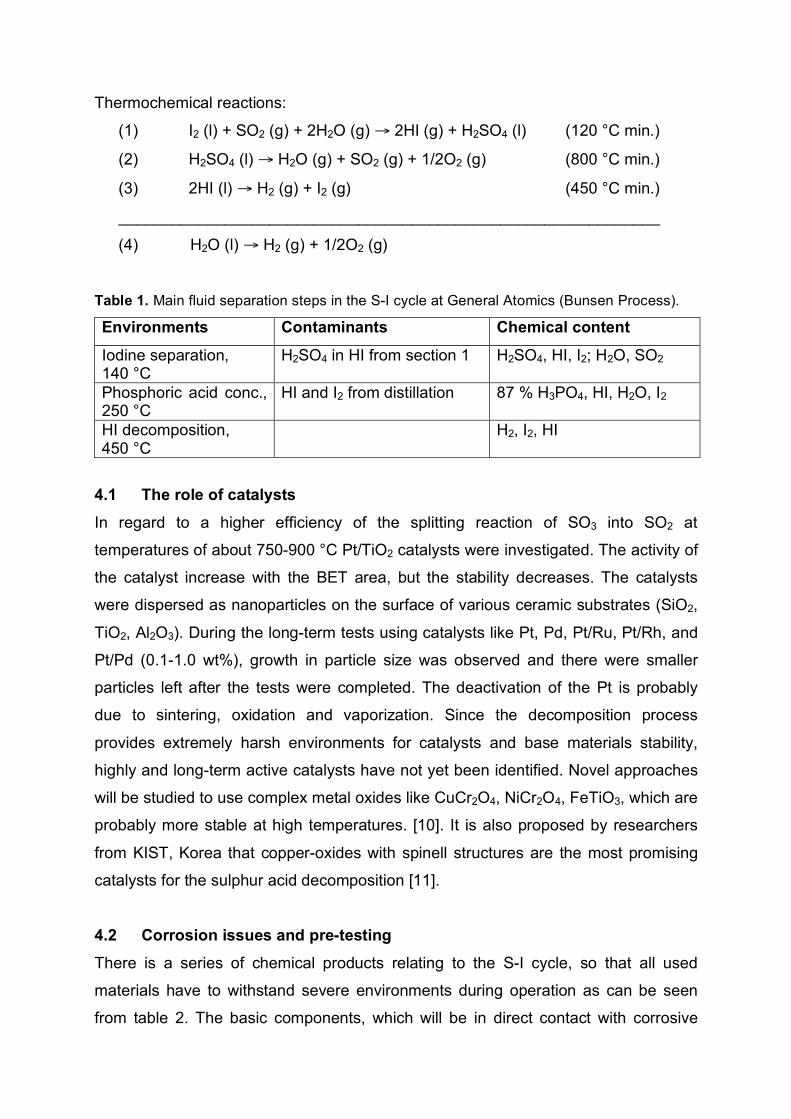
Table 1. Main fluid separation steps in the S-I cycle at General Atomics (Bunsen Process).
Environments Contaminants Chemical content
Iodine separation, 140 °C
H2SO4 in HI from section 1 H2SO4, HI, I2; H2O, SO2
Phosphoric acid conc., 250 °C
HI and I2 from distillation 87 % H3PO4, HI, H2O, I2
HI decomposition, 450 °C
H2, I2, HI
4.1 The role of catalysts
In regard to a higher efficiency of the splitting reaction of SO3 into SO2 at
temperatures of about 750-900 °C Pt/TiO2 catalysts were investigated. The activity of
the catalyst increase with the BET area, but the stability decreases. The catalysts
were dispersed as nanoparticles on the surface of various ceramic substrates (SiO2,
TiO2, Al2O3). During the long-term tests using catalysts like Pt, Pd, Pt/Ru, Pt/Rh, and
Pt/Pd (0.1-1.0 wt%), growth in particle size was observed and there were smaller
particles left after the tests were completed. The deactivation of the Pt is probably
due to sintering, oxidation and vaporization. Since the decomposition process
provides extremely harsh environments for catalysts and base materials stability,
highly and long-term active catalysts have not yet been identified. Novel approaches
will be studied to use complex metal oxides like CuCr2O4, NiCr2O4, FeTiO3, which are
probably more stable at high temperatures. [10]. It is also proposed by researchers
from KIST, Korea that copper-oxides with spinell structures are the most promising
catalysts for the sulphur acid decomposition [11].
4.2 Corrosion issues and pre-testing
There is a series of chemical products relating to the S-I cycle, so that all used
materials have to withstand severe environments during operation as can be seen
from table 2. The basic components, which will be in direct contact with corrosive

liquids or gases are tubes, vessels, boilers, and heat-exchangers. Post-investigations
of the materials must be concentrated on the microstructural changes and their
corrosion and oxidation behavior in order to predict the lifetime of the components.
Table 2. Corrosion test matrix for materials w/wo coating within S-I cycle.
Environments Temperature Responsibility
H2SO4-Decomp., SO3/SO2 850 °C SNL
HIx-Decomp.
H3PO4 (95 %) Conc.
Iodine Sep.
140 °C
250 °C
450 °C
GA
GA
GA
Liquid salts 900 °C ORNL
Corrosion tests with sulfur acid decomposition inside SiC based ceramic HX
channels were already performed by Ceramatec Inc. from 450 °C up to 900 °C under
exposure of steam, H2SO4 (gas), oxygen and nitrogen [12]. The exposure time was
up to 1000 h. Flow rates of about 2.0 sccm were chosen in liquid (acid/water mix)
and 150 sccm in air. Different mole fractions were maintained: water 30, 60 %,
H2SO4: 30, 60 %, oxygen: 29.5 %, nitrogen: 0.5, 8 %. Results from 1000 h exposure
of SiC specimens showed only little effect on the flexural strength and low weight
gain. A decrease in corrosion rate was observed with exposure time. Slightly
oxidation could be determined but no excessive damage occurred. The silica scale
showed little contamination by K, Na, Ca, and Cl. From these results it could be
concluded that the corrosion resistance of SiC-based ceramics is most likely
controlled by the stability of the silica scale during operation. Crack or flaw healing
trough the silica scale can be assumed, because the flexure strength was slightly
increased.
Corrosion experiments related to the Iodine separation (HIx-H3PO4) and H3PO4
separation (85-96 wt% H3PO4-HI-H2O) were performed by General Atomics (GA) at
low temperatures of 140 °C and 250 °C, respectively. Especially tantalum and SiC
based materials showed no sign of corrosion after the tests with exposure times
ranging 120-1000 hours. Tantalum based materials were superior. These tests are
continuing. A weight gain could often be observed due to a phosphate layer that was
attached on the specimen’s surfaces [13].

5 Liquid Silicon Infiltrated (LSI) composites
Ceramic matrix composites (CMCs) have been investigated for nearly 18 years by
the German Aerospace Center (DLR), especially for space and aeronautics
applications. The motivation for the development was to overcome the brittleness of
monolithic ceramics by using fibres as a reinforcement phase. Since then C/C-SiC
composites, derived from carbon/carbon (C/C) preforms, can be manufactured with a
high variability of properties and are now commercially available [14]. The materials
can be manufactured with high reproducibility, due to stable fabrication process and
quality inspection. The typical processing includes three steps: CFRP manufacture,
pyrolysis and Si-melt infiltration. The properties of Si-infiltrated ceramic composites
are shown in table 3 and basically determined by the microstructure (fig. 1). Different
types of composites are known:
! XB composite: The XB composite is based on high tenacity fibres (HTA from
Tenax) and a liquid phenolic resin, providing a very high char yield exceeding
60 m%. The 2D fabrics are used as received without any further modification, except
a drying step at 100 °C for one hour in order to remove absorbed moisture. The use
of C-fibres yield dense segments of C/C-fibre bundles after pyrolysis, providing load
bearing C-fibres within a more or less weakly bonded carbon matrix, which protects
the fibre bundles from being siliconized. During pyrolysis only a few distinct
microcracks formed within the weak carbon matrix, which is the result of the high
fibre-matrix bonding. These type of composite as well as XD, XT, and XG composites
can be preferably fabricated by RTM or autoclave techniques.
! XD composite: If a fibre pre-treatment prior to CFRP manufacture is performed at
elevated temperatures, the microstructure of C/C-SiC could be significantly changed.
With increasing temperature of fibre pre-treatment, ranging from 600 to 1700 °C, the
formation of dense C/C-segments is hindered due to lower chemical bonds between
the fibres and the carbon matrix. Consequently, more and more randomly oriented
cracks are formed during the pyrolysis step, allowing an increasing amount of silicon
to enter these crack paths and decreasing the amount of load bearing carbon fibres.
! XT composite: Using moderate fibre pre-treatment temperature (e.g. 600 °C) in
combination with intermediate modulus fibres (T800, from Toray), the mechanical
strength values could be significantly increased compared with XB composites.
! XG composite: If different layers of thermally pre-treated 2D fabrics are combined
in a symmetrical lay-up within one composite, a gradient composite can be achieved.

The higher the pre-treatment temperature the higher will be the conversion rate of
carbon fibres inside the composite during the final Si-infiltration.
! SF composite: To obtain this type of composite inexpensive short carbon fibres
(HTA from Tenax) with different lengths of 5-40 mm are mixed with phenolic resin
(powder or liquid) to homogeneous compounds. The compounds are then molded by
axial pressing. This is the preferred technique to accomplish net-shape components
in series production at low costs. The series production of automobile brake discs is
based on this composite type revealing a gradient microstructure.
! B1 composite: The B1 composite type is a non-typical CMC, since it is
quasiisotropic and the properties are not dominated by the carbon fibres [15]. It can
be performed by using a mixture of very short carbon fibres (lengths < 1 mm),
phenolic powder resin, and inexpensive wood powders. The compound can be
molded into homogenous plates with thicknesses up to 60 mm as well as net-shape
parts. The microstructure is crack free and therefore gas-tight. Compared to other
CMCs the fibre content is only about 20-30 vol%. On the other hand the SiC and
silicon content is high and therefore the material has a much more higher brittleness.
This composite type shows a very high Young’s modulus and strength, which makes
it an interesting candidate for lightweight structures with high stiffness.
Table 3. Properties and composition of Si-infiltrated composites.
Unit XB XD XT XG SF B1
Density g/cm! 1.9 2.3 1.9 2.1 2.1-2.3 2.8
Open porosity Vol% 3.5 2.8 3.7 <5 1-3 <1
Flexural strength MPa 160 80 300 65-80 90-140 185
Tensile strength MPa 80 30 190 31 n.d. n.d.
Strain to failure (#) - 0.15 0.04 0.35 0.15-0.2 n.d. n.d.
Young´s Modulus GPa 60 100 60 41 50-70 294
Th. Cond. ($) W/mK 10 19 13 19 25-30 45
CTE (%) 10-6
K-1
2.5-6.5 4.5 2.5 n.d. 1.0-4.0 2.6
Si-content M% 6 2 5 3 4 33
SiC-content M% 33 61 31 47 44 59
C-content M% 61 37 64 50 52 8
(n.d. = not determined)
All properties were determined at RT from DLR prototype materials, which were
performed in-house. The density and porosity were determined by the Archimedes
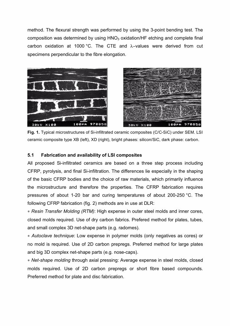
method. The flexural strength was performed by using the 3-point bending test. The
composition was determined by using HNO3 oxidation/HF etching and complete final
carbon oxidation at 1000 °C. The CTE and $&values were derived from cut
specimens perpendicular to the fibre elongation.
Fig. 1. Typical microstructures of Si-infiltrated ceramic composites (C/C-SiC) under SEM. LSI
ceramic composite type XB (left), XD (right), bright phases: silicon/SiC, dark phase: carbon.
5.1 Fabrication and availability of LSI composites
All proposed Si-infiltrated ceramics are based on a three step process including
CFRP, pyrolysis, and final Si-infiltration. The differences lie especially in the shaping
of the basic CFRP bodies and the choice of raw materials, which primarily influence
the microstructure and therefore the properties. The CFRP fabrication requires
pressures of about 1-20 bar and curing temperatures of about 200-250 °C. The
following CFRP fabrication (fig. 2) methods are in use at DLR:
! Resin Transfer Molding (RTM): High expense in outer steel molds and inner cores,
closed molds required. Use of dry carbon fabrics. Prefered method for plates, tubes,
and small complex 3D net-shape parts (e.g. radomes).
! Autoclave technique: Low expense in polymer molds (only negatives as cores) or
no mold is required. Use of 2D carbon prepregs. Preferred method for large plates
and big 3D complex net-shape parts (e.g. nose-caps).
! Net-shape molding through axial pressing: Average expense in steel molds, closed
molds required. Use of 2D carbon prepregs or short fibre based compounds.
Preferred method for plate and disc fabrication.

Fig. 2. Schematic representation of common CFRP fabrication methods using phenolic resin
and carbon fibres as raw materials. From left to right: RTM, autoclave, hot molding.
Due to the limited size and volume of the present high temperature furnaces
(pyrolysis and siliconization) CFRP parts with maximum dimensions of about 800-
900 mm were fabricated. However, the methods allow the manufacture of bigger
parts. Components with thicknesses > 5 mm must be processed very carefully,
because delaminations might occur due to weak fibre-matrix bonding. Very complex
shaped parts can also be performed by joining C/C semi-finished products,
preferentially after pyrolysis, e.g. tubes with flanges (fig. 3, 4). To obtain accurate in-
situ joinings the single parts must be machined with low tolerances (± 0.2 mm).
Fig. 3. Semi-finished parts made from carbon/carbon after machining to be ready for joining.
F
Carbon short fibe rs Dry carbon
fabric
Carbon prepreg
resin
valve valve
heating Vacuum bag
P
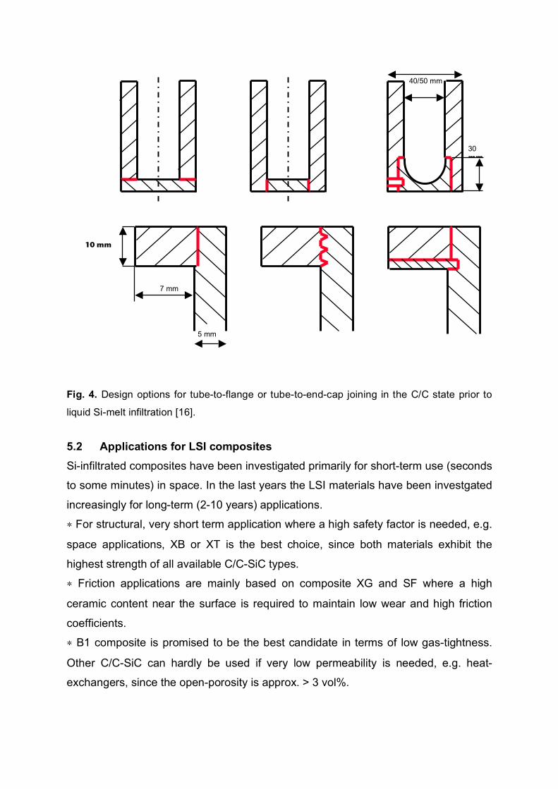
Fig. 4. Design options for tube-to-flange or tube-to-end-cap joining in the C/C state prior to
liquid Si-melt infiltration [16].
5.2 Applications for LSI composites
Si-infiltrated composites have been investigated primarily for short-term use (seconds
to some minutes) in space. In the last years the LSI materials have been investgated
increasingly for long-term (2-10 years) applications.
! For structural, very short term application where a high safety factor is needed, e.g.
space applications, XB or XT is the best choice, since both materials exhibit the
highest strength of all available C/C-SiC types.
! Friction applications are mainly based on composite XG and SF where a high
ceramic content near the surface is required to maintain low wear and high friction
coefficients.
! B1 composite is promised to be the best candidate in terms of low gas-tightness.
Other C/C-SiC can hardly be used if very low permeability is needed, e.g. heat-
exchangers, since the open-porosity is approx. > 3 vol%.
5 mm
7 mm
40/50 mm
30 mm
10 mm
! Most of the C/C-SiC composites show poor oxidation resistance. This starts at
about 400 °C and therefore the composites need an additional coating when used in
air or combustion environments (e.g. gas turbine components).
! SF or B1 ceramics can be used for applications where high stiffness, high thermal
conductivity or low oxidation is required, due to the high ceramic content.
! For the long-term use of any LSI composite at high temperature protection surface
coatings will mostly be necessary.
5.3 Surface protection coatings on LSI composites
Due to the oxidation of carbon above 400 °C, C/C-SiC composites have to be
protected with a dense layer providing a low rate of oxygen diffusion into the
composite as well as a low rate of carbon diffusion out of the material. To protect the
ceramic substrate (Si, SiC) from oxidation and corrosion in combustion
environments, e.g. water vapor, an additional environmental barrier coating is
needed. The degradation of the composites will be also sharply increased when they
are used at temperatures much higher than 1200 °C and or under thermal cycling
conditions. Different coatings, which can be applied by chemical vapor deposition
(CVD) or vacuum plasma spraying (VPS) were already investigated or are under
consideration:
! SiC: CVD-SiC with a thickness of about 50-200 µm can be applied by using
trichlorosilane as a precursor. In air a thin silica layer is formed on the top of the
CVD-SiC layer, providing oxidation protection at high temperatures. The microcracks
will be filled with silica and block the access to oxygen at elevated temperatures
> 1100 °C.
! BoraSiC: Multilayer CVD-BoraSiC coating is a three layer coating (SiC-B2O3-SiC),
which provides an additional self-healing mechanism due the formation of boron
oxide at about 900 °C [17, 18].
! Yttrium silicates: Y-silicates are suitable candidates due to their low coefficients of
thermal expansion (4.6-4.8 ! 10-6 K-1). These coatings show typical thicknesses of
40-150 µm and can be applied through vacuum plasma spraying (VPS) techniques.
The suitability of oxidation protection was successfully demonstrated by thermal
cycling tests as well as in plasma wind tunnel tests under re-entry conditions [19].
! Cordierite: Cordierite (2MgO!2Al2O3!3SiO2) provides an excellent protection in
oxidative atmosphere as well as under corrosive conditions. It can be also applied on
the surface of LSI composites via VPS with thicknesses ranging from 50-400 µm [20].
! Pyrocarbon: Highly pure Pyrocarbon (PyC) coating can be performed by pyrolysis
of hydrocarbon gases. This coating exhibits a highly orientated and isotropic
structure. It is primarily used for sealing surfaces of graphite and C/C components,
which enable a wider use. The sealing prevents the surface from particle release.
Furthermore, chemical cannot infiltrate porous structures of graphite and C/C. The
compatibility with LSI composites has not already been investigated. Due to the
excellent resistance of PyC to liquid salts, which is significantly higher than that of
graphite and C/C materials, the components show a higher lifetime in corrosive
environments, e.g. if components are in direct contact to salt melts under reducing
conditions. Whenever highest purity and/or chemical resistance and/or low particle
release are required, a Pyrocarbon coating is the ideal choice.
6 Fields of application for LSI composites to HT (S-I) process
6.1 Tubes for liquid-salt heat transfer
Liquid-salts are known to have the potential to be corrosive, especially when they
have impurities and are used at high temperatures up to 1000 °C. It is also known
that temperature gradients, which might occur during their heat-transfer lead to
mechanical stresses. For this reasons materials with high corrosion resistance, high
strength and strain to failure are required.
Tubes fabricated from XB or XT composites might be a good choice for the piping of
liquid salts from the nuclear reactor intermediate heat-exchanger to process heat
exchangers if they can meet requirements for corrosion and erosion resistance in
combination with low permeability. The resistance of these composites can be
improved by coating them with Pyrocarbon or CVD-SiC. By this surface modification
the wetting behaviour can also be sharply influenced.
The basic manufacture methods for tubes will be based on winding 2D carbon fabrics
or prepregs on uniform cores. The outer diameters of these cores have to be
machined from bulk materials like steel or plastic billets. The preferred technique will
be based on autoclave manufacture, since tubes up to a length of some meters might

be possible. The RTM technique, already proven for tubes with Ø 50/40 mm and up
to lengths of about 850 mm, will be also one possibility for first prototypes but
requires a high expense in molds, especially when the diameter of the tubes will be
changed. The tube size is then also limited in its diameter and in its length. Different
joining designs were already proposed to modify the open ends so that they could be
clamped together [16].
6.2 Plate-type heat exchangers
The compact heat exchanger requires a highly gas-tight material. On the other hand
the proposed design is based on micro-channels, which are in the mm-scale. For
these reasons 2D fibre reinforced LSI composites and even typically short carbon
fibres with fibre lengths of about 5-40 mm most likely cannot be used. Such carbon
fibres are very stiff and cannot be molded in the desired shape. In addition, the gas
permeability of these composites will be too high. Therefore the technical approach
must be focused on B1 composite or other commercial SiC ceramics.
DLR proposes a concept using the B1 composite, which contains short carbon fibres,
phenolic resin and wood powder. Silicon or SiC powder can be added to reduce the
shrinkage and mass loss during pyrolysis. The length of the carbon fibres and grains
is preferably less than 1 mm, so that small channels can be created by molding. It is
important to maintain a homogeneous mixing of the basic components to obtain a
homogeneous material distribution of the single components.
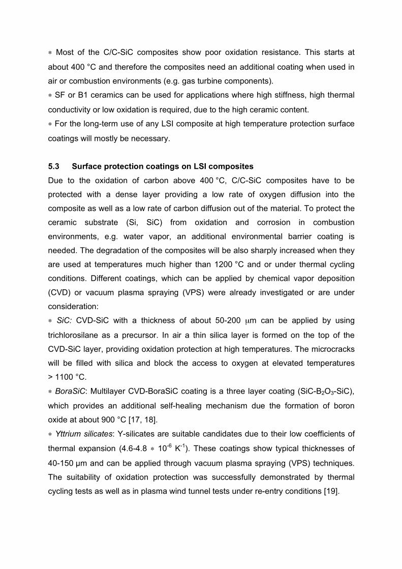
The fabrication of homogeneous net-shape wood based composite (WBC) plates is
one of the critical process steps, because all defects will remain in the final ceramic
structure. Inhomogenities like closed pores or carbon accumulations will reduce the
strength of the composite. Therefore the fabrication of the “green body” must be
performed with high accuracy and with high reproducibility. A first prototype with net-
shape molded flow channels can be seen in fig. 5, left. Fabrication through molding
must be favored, since it is likely to be too expensive to machine carbon bulk material
(fig. 5 right). The net-shape fabrication also limits the failure probability, since the
machining of porous carbon is expected to cause cracks.
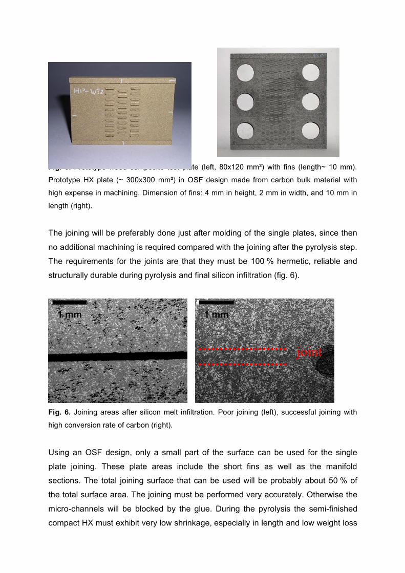
Fig. 5. Prototype wood composite test plate (left, 80x120 mm") with fins (length~ 10 mm).
Prototype HX plate (~ 300x300 mm") in OSF design made from carbon bulk material with
high expense in machining. Dimension of fins: 4 mm in height, 2 mm in width, and 10 mm in
length (right).
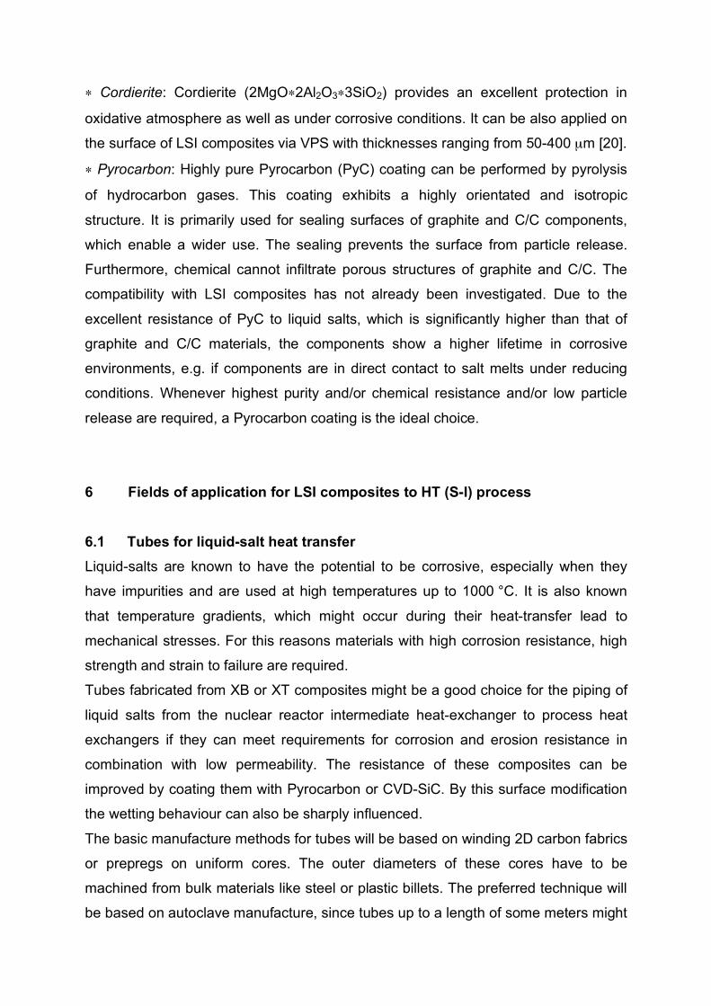
The joining will be preferably done just after molding of the single plates, since then
no additional machining is required compared with the joining after the pyrolysis step.
The requirements for the joints are that they must be 100 % hermetic, reliable and
structurally durable during pyrolysis and final silicon infiltration (fig. 6).
Fig. 6. Joining areas after silicon melt infiltration. Poor joining (left), successful joining with
high conversion rate of carbon (right).
Using an OSF design, only a small part of the surface can be used for the single
plate joining. These plate areas include the short fins as well as the manifold
sections. The total joining surface that can be used will be probably about 50 % of
the total surface area. The joining must be performed very accurately. Otherwise the
micro-channels will be blocked by the glue. During the pyrolysis the semi-finished
compact HX must exhibit very low shrinkage, especially in length and low weight loss
1 mm 1 mm
joint

to maintain its structural integrity. During the final in-situ infiltration of the 3D compact
with liquid silicon most of the carbon, including the joints, must be converted into SiC
and the open porosity (Ø ~50 µm) of the carbon bulk material must be filled with pure
silicon. However, all the channels (Ø ~1-2 mm) must remain open. At least three
different infiltration methods are known (fig. 7), which can be used for the final silicon
infiltration.
Fig. 7. Methods for pressureless liquid silicon melt infiltration into porous carbon preforms at
about 1650 °C. Direct contact method (1), wick method (2), and drop method (3).
If the HX will be used as a chemical reactor for thermal decomposition reactions
there will be a strong need to deposit catalysts on some areas of the flow channels,
or to insert catalyst-coated granules into the channels. Coatings can probably be
applied either during the mixing process of the compounds or after the final Si-
infiltration by using CVI methods. The insertion of granules most likely must occur
after infiltration, and thus requires attention to the geometry of the flow channels.
An internal coating may be also necessary when molten salts are used as a primary
coolant or even to enhance the gas-tightness. In this case Pyrocarbon or CVD-SiC
must be applied on the top of the flow channels.
There are still some key challenges to obtain a higher technology readiness level in
the fabrication of HX plates based on B1 composite:
! Improvement of powder mixing and granulation methods to enhance the materials
homogeneity, especially in the “green stage”.
! Accurate net-shape molding of channels/OSF-design by using improved
compounds with low viscosity and adapted molding tools.
! Development of reliable joining methods for net-shape plates (2-10 joinings).
! Accurate Si-melt infiltration.
Si-
Vorlage
1 3
2
Si
Si
C-Preform Si
C-Preform C-Preform
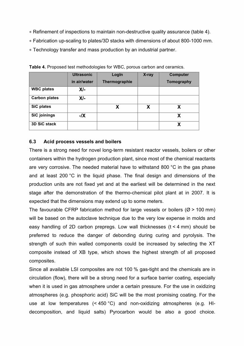
! Refinement of inspections to maintain non-destructive quality assurance (table 4).
! Fabrication up-scaling to plates/3D stacks with dimensions of about 800-1000 mm.
! Technology transfer and mass production by an industrial partner.
Table 4. Proposed test methodologies for WBC, porous carbon and ceramics.
Ultrasonic
in air/water
LogIn
Thermographie
X-ray Computer
Tomography
WBC plates X/-
Carbon plates X/-
SiC plates X X X
SiC joinings -/X X
3D SiC stack X
6.3 Acid process vessels and boilers
There is a strong need for novel long-term resistant reactor vessels, boilers or other
containers within the hydrogen production plant, since most of the chemical reactants
are very corrosive. The needed material have to withstand 800 °C in the gas phase
and at least 200 °C in the liquid phase. The final design and dimensions of the
production units are not fixed yet and at the earliest will be determined in the next
stage after the demonstration of the thermo-chemical pilot plant at in 2007. It is
expected that the dimensions may extend up to some meters.
The favourable CFRP fabrication method for large vessels or boilers (Ø > 100 mm)
will be based on the autoclave technique due to the very low expense in molds and
easy handling of 2D carbon prepregs. Low wall thicknesses (t < 4 mm) should be
preferred to reduce the danger of debonding during curing and pyrolysis. The
strength of such thin walled components could be increased by selecting the XT
composite instead of XB type, which shows the highest strength of all proposed
composites.
Since all available LSI composites are not 100 % gas-tight and the chemicals are in
circulation (flow), there will be a strong need for a surface barrier coating, especially
when it is used in gas atmosphere under a certain pressure. For the use in oxidizing
atmospheres (e.g. phosphoric acid) SiC will be the most promising coating. For the
use at low temperatures (< 450 °C) and non-oxidizing atmospheres (e.g. HI-
decomposition, and liquid salts) Pyrocarbon would be also a good choice.
Nevertheless, the gas-tightness of coated LSI composites will be probably limited to
low gas pressures and pressure differences.
If complex shaped components in combination with very high gas-tightness are
required, the use of B1 composite or commercial SiC must be taken into account.
These materials can be machined in the semi-finished C/C or SiC state and then
joined prior to the final Si-infiltration or sintering. However, these ceramics are much
more brittle than 2D carbon fibre reinforced grades and therefore exhibit only modest
thermo-shock resistance.
7 Recommendations for the use of LSI composites
From the proposed LSI materials described in table 1 XB, XT, and B1 will be the
most promising candidates in the corrosion environments required for S-I processing.
The coupon testing should be done in HI, phosphoric acid, sulphuric acid and liquid
salts as can be derived from table 2.
The first test campaign should be concentrated on small test coupons with diameters
of Ø ~30-50 mm. It is proposed to use at least 3 specimens of each type per test,
because of the scattering in its composition or inhomogenities, which sometimes
occur within LSI composites. The strength, density and porosity of these samples
should be determined prior to the testing. The samples should be tested with and
without an external coating. Preferred coatings are CVD-SiC and Pyrocarbon. Short-
term tests as well as long-term tests, at least up to 1000 hours should be performed.
Post-test investigation of the selected materials are recommended, which should
determine the changes in microstructure, chemical composition as well as in
mechanical strength.
In case that the performance of the LSI composites is sufficient, prototype
components should be fabricated and a potentially fabrication for up-scaling should
be discussed.
Since there is a great demand for HXs as the key elements for the S-I technology,
most of the future work should be concentrated to proof the molding of the proposed
flow-channel designs and to scale-up the fabrication to an industrial level. Because
the final design is not fixed yet, the investigations should be concentrated on a broad
dimensional variety of flow channels as well as on the joining, and accurate Si-
infiltration. The optimization of at least 5 process steps, like mixing, molding, joining,
pyrolysis and Si-infiltration is required. It is necessary to perform a two years
research program to accomplish a prototype compact HX with the proposed OSF
design. The fabrication must be accompanied by leakage tests to proof the gas-
tightness of the single layers and the joinings. To show the improvement through the
coatings, it also must be shown that CVD-SiC or Pyrocarbon can be applied to the
surfaces, including internal flow passages in the HX’s.
References
[1] Future Reactor Materials - A Revolutionary Reactor concept – ORNL Review Vol. 37,
No.1, (2004)
[2] D. F. Williams: Assessment of candidate molten salt coolants for the NGNP/NHI heat-
transfer loop, ORNTL-report/TM-2006/69, www.sti.gov/bridge, (2006)
[3] L.C. Olson et al.: Evaluation of material corrosion in molten flouride salt, Presentation
on AIChE conference, San-Francisco, Nov. 12-17, (2006)
[4] P. F. Peterson et al.: Development of C-SiC ceramic compact HX for high-temperature
heat transfer application, Proc. of AIChE conference, Nov. 12-17, San Francisco,
(2006)
[5] V. Ponyavin et al: Modeling and parametric study of a ceramic high temperature heat
exchanger and chemical decomposer, Proc. of IMECE, Nov. 5-10, Chicago, (2006)
[6] J. Cutts et al.: Dynamic flow of micro-channels in a ceramic heat exchanger, Proc. of
AIChE conference, Nov. 12-17, San Francisco, (2006)
[7] M. A. Wilson et al.: Optimizing the micro-channels features in a ceramic heat-
exchanger for sulphuric acid decomposition, Proc. of AIChE conference, Nov. 12-17,
San Francisco, (2006)
[8] Development of advanced high temperature heat exchanger, Proposal to DOE from
UNLV, http://nstg.nevada.edu/heatexchangers1.html, July 1, (2003)
[9] W. Sweet et al.: Experimental results for the generation of hydrogen by the
decomposition of hydrogen Iodide in the Sulphur-Iodine Cycle, Presentation on AIChE
conference, Nov. 12-17, San Francisco, (2006)
[10] D. M. Ginosar et al.: Platinum group metal catalysts for sulfur based thermochemical
water splitting cycles, Proc. of AIChE conference, Nov. 12-17, San Francisco, (2006)
[11] K.-D. Jung et al.: Decomposition of sulphuric acid to produce sulphur dioxide and
oxygen in Is cycle, Presentation on AIChE conference, Nov. 12-17, San Francisco,
(2006)
[12] C. Lewinsohn et al.: High temperature ceramic heat exchanger material, UNLV/DOE
NHI Review: July 25, 2006, http://nstg.nevada.edu/heatexchangers1.html, (2006)
[13] B. Wong, L. Brown, G. Besenbruch: Corrosion and crack growth studies of HX
construction materials for HI decomposition, IFT/P2006-063,
http://nstg.nevada.edu/heatexchangers1.html, (2006)
[14] W. Krenkel; J. M. Hausherr; T. Reimer; M. Frieß: Design, manufacture and quality
assurance of C/C-SiC composites for space transportation systems, Proc. of 28th Int.
Conf. on Adv. Cer. and Comp., Cocoa Beach, (2004)
[15] A. Hofenauer; O. Treusch; F. Tröger; G. Wegener; J. Fromm; M. Gahr; J. Schmidt; W.
Krenkel: Dense reaction infiltrated silicon/silicon carbide ceramics derived from wood
based composites, AEM, WILEY-VCH, Weinheim, 5, No.11, p. 794-799, (2003)
[16] J. Schmidt; J. Schulte-Fischedick; M. Scheiffele; U. Kröner; W. Krenkel; R. Tamme:
Wärmeübertrager aus Faserkeramikrohren für den Einsatz in der Energietechnik, in
Verbundwerkstoffe (Hrsg.: H. P. Degischer), WILEY-VCH, Weinheim, S. 808-813,
(2003)
[17] R. Weiss: Carbon Fibre reinforced CMCs: manufacture, properties, oxidation
protection, Proc. of HTCMC4 (Eds.: W. Krenkel, R. Naslain, H. Schneider), WILEY-
VCH, Weinheim, p. 440-456, (2001)
[18] E. Cordano; C. Mao; M. Labanti; G. Martignani; G.L. Minoccari; L. Pilotti; R. Weiss; J.
Schmidt: Oxidation testing and mechanical characterisation of BoraSiC coated C/C-SiC
composites, Materials Week 2002, International Congress on Advanced Materials their
Processes and Applications, published on CD, Munich, (2002)
[19] Ullmann, M. Schmücker, H. Hald, R. Henne, H. Schneider: Yttrium-silicates for
oxidation protection of C/C-SiC composites, Proc. of HTCMC4 (Eds.: W. Krenkel, R.
Naslain, H. Schneider), WILEY-VCH, Weinheim, p. 230-235, (2001)
[20] J. Schmidt; J. Schulte-Fischedick; E. Cordano, C. Mao, V. Liedtke, R. Fordham: CMC
tubes based on C/C-SiC with high oxidation and corrosion resistance, Proceedings of
the 5th international conference on high temperature ceramic matrix composites, ed. by
M. Singh, R. Kerans, E. Lara-Curzio, R. Naslain, published by the American Ceramic
Society, p. 531-536, (2004)