portable wind turbine blade leading edge erosion test
TRANSCRIPT
Portable Wind Turbine Blade Leading Edge Erosion Test
Final Design Review November 24, 2020
by
Joe Blakewell, [email protected]
Tim Holt, [email protected]
Kevin Vartan, [email protected]
for
Turbine Technology Partners, LLC (TTP)
Mechanical Engineering Department
California Polytechnic State University San Luis Obispo
2020

2
Executive Summary
Turbine Technology Partners, LLC (TTP) is a company located in Santa Barbara, California that
provides expert independent engineering (IE) consulting services to the wind energy industry -
supporting its goal of generating cost effective and reliable carbon-free renewal energy for the
world. TTP customers include some of the largest wind turbine original equipment
manufacturers (OEMs), wind turbine power plant developers, and wind turbine owner/operators.
One of the biggest problems challenging the wind energy industry currently is the power loss
that results from the leading edge (LE) erosion of wind turbine blades. The purpose of our senior
design project is to create an erosion test chamber that will simulate erosion conditions and
compare the relative effectiveness of different erosion-resistant solutions, such as coatings or
tapes. This document highlights our team’s goals for the project, which are a result of sponsor
and user interviews, technical background research, product research, and project objectives
research. Our key findings from research and interviews are that testing units for LE protection
solutions should follow the guidelines set forth in the recommended practices 0171 from Det
Norske Veritas Germanischer Lloyd (DNVGL), an international accredited energy registrar. We
have gone through a rigorous design process to come up with the design that we have chosen as
our final design. The included Gantt chart shows our project’s timeline of completion.
This document, the Final Design Review (FDR), is designed to describe the process by which
ideation and down-selection occurred and to explain and defend the chosen concept.
Statement of Disclaimer
Since this project is a result of a class assignment, it has been graded and accepted as fulfillment
of the course requirements. Acceptance does not imply technical accuracy or reliability. Any
use of information in this report is done at the risk of the user. These risks may include
catastrophic failure of the device or infringement of patent or copyright laws. California
Polytechnic State University at San Luis Obispo and its staff cannot be held liable for any use or
misuse of the project.

3
Table of Contents
1. Introduction ................................................................................................................................7
2. Background ................................................................................................................................7
2.1 Turbine Blade Makeup................................................................................................7
2.2 LE Erosion Main Causes .............................................................................................8
2.3 Current Solutions .........................................................................................................9
2.4 Current Testing Machines on the Market ...............................................................10
2.5 DNVGL Recommended Practices ............................................................................10
3. Objectives..................................................................................................................................11
3.1 Problem Definition .....................................................................................................11
3.2 Boundary Diagram ....................................................................................................11
4. Concept Design .........................................................................................................................14
4.1 Design Selection Process ............................................................................................14
4.2 Design Based on Analysis and Hazard Prevention .................................................18
5. Final Design ..............................................................................................................................20
5.1 Structural Support Design ........................................................................................21
5.2 Fluid Path Design .......................................................................................................25
5.3 Reservoir Design ........................................................................................................30
5.4 Rotating Blade System ...............................................................................................30
5.5 Safety and Maintenance ............................................................................................33
5.6 Cost Overview ............................................................................................................34
6. Manufacturing..........................................................................................................................34
6.1 Procurement ...............................................................................................................34
6.2 Manufacturing............................................................................................................34
6.3 Assembly .....................................................................................................................36
6.4 Outsourcing ................................................................................................................37
7. Design Verification Chapter ...................................................................................................37
7.1 Dropper Configuration Verification .......................................................................37
7.2 Finite Element Analysis .............................................................................................39
8. Project Management ................................................................................................................52
8.1 Completed Analysis ...................................................................................................53
8.2 Purchases ....................................................................................................................53
8.3 Effectiveness of Planning ...........................................................................................54
9. Conclusions and Recommendations .......................................................................................54
References .....................................................................................................................................55
Appendix A: Relevant Patents ................................................................................................. A-1
Appendix B: Quality Function Deployment ............................................................................B-1
Appendix C: Ideas from Ideation ............................................................................................ C-1
Appendix D: Pugh Matrices ..................................................................................................... D-1
Appendix E: Morphological Matrix .........................................................................................E-1
Appendix F: Weighted Decision Matrix .................................................................................. F-1
Appendix G: Design Hazard Checklist .................................................................................. G-1
Appendix H: Preliminary Calculations ................................................................................. H-1
Appendix I: Gantt Chart ............................................................................................................ I-1
Appendix J: Concept Model Build Day Images ..................................................................... J-1
Appendix K: DVP&R .............................................................................................................. K-1

4
Appendix L: Indented Bill of Materials ...................................................................................L-1
Appendix M: Design Verification Plan ................................................................................. M-1
Appendix N: Water Drop Spacing Calculations .................................................................... N-1
Appendix O: Links to each part .............................................................................................. O-1
Appendix P: Failure Modes and Effects Analysis ................................................................... P-1
Appendix Q: Centrifugal Force Excel Calculation ............................................................... Q-1
Appendix R: Bolt Stress Excel Calculations .......................................................................... R-1
Appendix S: EES File For One Dropper Configuration ........................................................ S-1
Appendix T: Screenshot of Excel File ‘ME 430 Experiment Data’.......................................T-1
Appendix U: MatLab Script for fluid Pathway through FDS .............................................. U-1
Appendix V: Technical Drawing Package ............................................................................. V-1
5
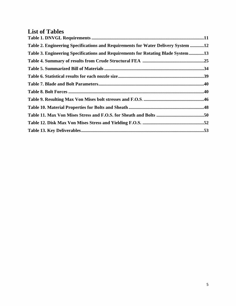
List of Tables
Table 1. DNVGL Requirements .................................................................................................11
Table 2. Engineering Specifications and Requirements for Water Delivery System ............12
Table 3. Engineering Specifications and Requirements for Rotating Blade System .............13
Table 4. Summary of results from Crude Structural FEA .....................................................25
Table 5. Summarized Bill of Materials ......................................................................................34
Table 6. Statistical results for each nozzle size ..........................................................................39
Table 7. Blade and Bolt Parameters ...........................................................................................40
Table 8. Bolt Forces .....................................................................................................................40
Table 9. Resulting Max Von Mises bolt stresses and F.O.S. ....................................................46
Table 10. Material Properties for Bolts and Sheath .................................................................48
Table 11. Max Von Mises Stress and F.O.S. for Sheath and Bolts .........................................50
Table 12. Disk Max Von Mises Stress and Yielding F.O.S. .....................................................52
Table 13. Key Deliverables ..........................................................................................................53

6
List of Figures
Figure 1. Section view of a standard wind turbine blade ...........................................................9
Figure 2. Sandia Labs data for severe LE erosion and energy production losses .................10
Figure 3. R&D Test Systems turnkey solution to the LE testing problem .............................11
Figure 4. Leading Edge Erosion Tester Boundary Diagram ...................................................13
Figure 5. Straight leg supports, peristaltic pump driven system .............................................17
Figure 6. Arch supports, pressure driven dropper system ......................................................18
Figure 7. Cylinder support, rotating paddle to block satellite drops system .........................18
Figure 8. Telescoping leg supports, peristaltic pump driven system ......................................19
Figure 9. Wheeled leg supports, pressure driven dropper system .........................................19
Figure 10. Solidworks model of initial CAD concept................................................................20
Figure 11. Concept model prototype ..........................................................................................21
Figure 12. Peristaltic Pump CAD ...............................................................................................21
Figure 13. CAD assembly drawing .............................................................................................22
Figure 14. Support Structure design ..........................................................................................23
Figure 15. Leg design for structural support ............................................................................24
Figure 16. Crude leg deflection FEA with conservative 50 lbf load per leg ...........................24
Figure 17. Crude leg stress FEA with conservative 50 lbf load per leg .................................25
Figure 18. Support ring dimensions ...........................................................................................26
Figure 19. Crude ring deflection FEA with conservative 200 lbf load ....................................26
Figure 20. Crude ring stress FEA with conservative 200 lbf load ..........................................27
Figure 21. Peristaltic pump and inside view ..............................................................................27
Figure 22. In-line tubing filter ....................................................................................................28
Figure 23. Barbed reducer tubing fitting ...................................................................................28
Figure 24. Barbed Y-connector ..................................................................................................28
Figure 25. 1:12 flow splitter ........................................................................................................28
Figure 26. Dropper configuration ..............................................................................................29
Figure 27. ¼” tubing to ½” NPT male adapter .........................................................................29
Figure 28. Dropper assembly PVC .............................................................................................29
Figure 29. Thread-to-luer lock adapter .....................................................................................30
Figure 30. 32 Ga nozzle ...............................................................................................................30
Figure 31. PVC rail ......................................................................................................................31
Figure 32. Nozzles for creating the 2mm drop ..........................................................................31
Figure 33. Reservoir.....................................................................................................................32
Figure 34. Rotating blade system ...............................................................................................33
Figure 35. DU 96-W-180 6061 aluminum airfoil blade ............................................................33
Figure 36. Central mounting disk...............................................................................................34
Figure 37. Blade sheath ...............................................................................................................34
Figure 38. Verification prototype for nozzle sizing test............................................................37
Figure 39. Custom dropper configuration .................................................................................38
Figure 40. Experimental setup for drop collection with our verification prototype .............39
Figure 41. Average drop size results ..........................................................................................40
Figure 42. Blade FBD ..................................................................................................................42
Figure 43. System Loading ..........................................................................................................43
Figure 44. Blade/Bolt Assembly ..................................................................................................43
Figure 45. Model 1 Centrifugal Body Force Loading ...............................................................43
7
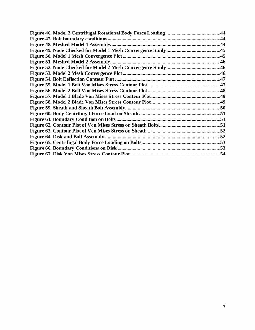
Figure 46. Model 2 Centrifugal Rotational Body Force Loading ............................................44
Figure 47. Bolt boundary conditions ..........................................................................................44
Figure 48. Meshed Model 1 Assembly........................................................................................44
Figure 49. Node Checked for Model 1 Mesh Convergence Study ...........................................45
Figure 50. Model 1 Mesh Convergence Plot ..............................................................................45
Figure 51. Meshed Model 2 Assembly........................................................................................46
Figure 52. Node Checked for Model 2 Mesh Convergence Study ...........................................46
Figure 53. Model 2 Mesh Convergence Plot ..............................................................................46
Figure 54. Bolt Deflection Contour Plot ....................................................................................47
Figure 55. Model 1 Bolt Von Mises Stress Contour Plot ..........................................................47
Figure 56. Model 2 Bolt Von Mises Stress Contour Plot ..........................................................48
Figure 57. Model 1 Blade Von Mises Stress Contour Plot .......................................................49
Figure 58. Model 2 Blade Von Mises Stress Contour Plot .......................................................49
Figure 59. Sheath and Sheath Bolt Assembly ............................................................................50
Figure 60. Body Centrifugal Force Load on Sheath .................................................................51
Figure 61. Boundary Condition on Bolts ...................................................................................51
Figure 62. Contour Plot of Von Mises Stress on Sheath Bolts .................................................51
Figure 63. Contour Plot of Von Mises Stress on Sheath ..........................................................52
Figure 64. Disk and Bolt Assembly ............................................................................................52
Figure 65. Centrifugal Body Force Loading on Bolts ...............................................................53
Figure 66. Boundary Conditions on Disk ..................................................................................53
Figure 67. Disk Von Mises Stress Contour Plot ........................................................................54

8
1. Introduction
Our team is made up of three fourth-year students studying mechanical engineering at Cal Poly
San Luis Obispo. We have partnered with Turbine Technology Partners (TTP) to design the
water delivery system and rotating blade system for a turbine blade coating testing unit. TTP is a
consulting company based in Santa Barbara, CA with specialized experience in the wind power
industry. Recently, they have been working to develop blade coatings that provide leading-edge
protection from erosion during turbine operation. The testing unit is needed to verify the degree
of leading-edge protection that the TTP blade coating solutions provide relative to their industry
competition. We agreed to work with TTP from January 2020 to December 2020 to develop the
water delivery system and designs for the rotation system for this testing unit. This document
goes over the background research, objectives, and design process and timeline for this project.
Due to the changing nature of things surrounding the COVID-19 pandemic, we agreed with TTP
that it was best to design the rotating blade system in place of building the water delivery system
designed in quarters 1 and 2.
2. Background
As wind turbine blades continue to get larger to keep up with demand for electricity, the blade
tips are reaching linear speeds of around 90-150 m/s, which is approximately 200-350 mph. This
high velocity leads to rapid erosion of the leading edge of composite blades, especially when
there is any surrounding precipitation. TTP has been developing protective leading-edge coatings
to solve this problem, but the product development presents a new challenge; product
verification. TTP needs a testing device to help them verify the effectiveness of their protective
coatings because reflecting on field data is too costly and time consuming. Our testing unit will
allow TTP to directly compare their new products with competitors and industry standards. Our
final product will meet the specifications outlined by TTP and the industry standards in DNVGL.
2.1 Turbine Blade Makeup
The blades on a wind turbine are fundamentally composed of two shells forming an airfoil shape
from thermosetting polymer matrix, e.g. epoxy or polyester, with reinforcing fibers [1]. These
two shells are bonded using adhesive and create the leading and trailing edges [2]. This airfoil‐
shaped blade is stiffened by spars or webs from balsa wood, foam, or combinations of both. The
underlying layer of polymer and reinforcing fibers is hereon referred to as substrate [3]. A
generalized picture of an airfoil can be seen below in Figure 1. Breakthrough refers to when the
erosion damage has penetrated the protective coating and breached the substrate.

9
Figure 1. Section view of a standard wind turbine blade [3]
All parts of the blade are subject to loading and failure, but the most common failure is the one
that we are being tasked with assisting; the erosion of the leading edge.
2.2 LE Erosion Main Causes
When the LE of an airfoil or wing is damaged, the performance of the blade is impacted far more
than when the trailing edge of the blade is damaged [4]. This is because the damaged LE trips the
boundary layer over the blade from laminar flow to turbulent flow, which makes the blade less
aerodynamically efficient [5].
Due to most wind farms being at or near sea level, rain is a far more common occurrence than
hail or snow [6]. This means that rain causes more damage than hail or snow to the LE of a wind
turbine blade [7]. The leading edge erosion problem is currently plaguing the wind energy
industry and has many companies competing to become the leading solution provider [8]. LE
erosion can be a huge problem for energy companies as the efficiency of the turbine decreases
significantly when the LE has eroded [9]. This causes massive losses in energy generation over
entire wind farms and therefore a large loss in profit for the energy companies. Sandia
Laboratory’s wind tunnel research at Texas A&M and found that the Annual Energy Production
(AEP) can be reduced up to 5% with significant LE erosion [10], as can be seen below in Figure
2.

10
Figure 2. Sandia Labs data for severe LE erosion and energy production losses[10]
It is difficult to replicate the conditions experienced by these turbines out in their true
environment, but several testing devices do exist to test out these blades and protective coatings.
They follow the DNVGL – RP0171 standard guidelines [11] which set safe and verified
operating procedures for LE erosion testing as put forth by ASTM G73-10 [12]. Since this is a
developing field with relatively little data to draw conclusions from, much of the design and
testing parameters are left up to the engineers who design the testing equipment and procedures
[13].
The exposure of the composite substrate to water could also pose significant threats to the
performance of the blade [14]. Primarily, the removal of any surface coating will mean that the
substrate itself will be exposed to further erosion [15].
2.3 Current Solutions
The technologies employed vary widely; however, the two most common approaches to creating
an effective surface coating are:
(1) In-mold application. A surface coating layer is added to the surface of the blade as
part of the molding process [16]. For manufacturing reasons, the coatings created
through this approach typically consist of a layer of material similar to that of the
matrix material used in the substrate (e.g. epoxy/polyester).
(2) Post-mold application. Surface coatings can be applied to the blade after the
molding process through painting or spraying. This approach allows more flexibility
with regards to material choice (in the absence of molding considerations), with
some manufacturers choosing to apply more ductile/elastic material components such
as polyurethanes. The industry is also currently using protective tape as a solution to
the LE problem. These technologies usually consist of a highly elastic and durable
polyurethane material, designed to (in some cases sacrificially) absorb the impact
energy from airborne particulates [17]. The tape is often very difficult to apply
correctly which leads to air pockets and a reduced time that the tape protects the
blade.

11
Manufacturers of tapes highlight the proposed benefits of applying elastomeric materials to the
leading edge (i.e. leading edge tapes), but also state that tapes must be replaced frequently as
they become worn [18].
2.4 Current Testing Machines on the Market
Despite this being a relatively small field, there are a few devices that perform similar tests to the
device we are going to design. During our patent search we found the ‘Wind Tunnel for
Erosion Testing’ which exposes samples to high winds and droplet impacts. This patent is listed
in Appendix A. The wind tunnel example is unique in that it is the only device that replicates
airflow over a blade tip by pushing air over the blade instead of accelerating the blade itself. The
remaining patents found in our search are also listed in Appendix A. They outline devices that
perform smaller functions within a testing unit. The University of Barcelona has a machine that
has a single arm with a single jet of water to perform repetitive impact testing. R&D Test
Systems offers a turnkey solution which includes the rain system, a rotor with test specimen
holders, drainage, ventilation and control system delivered in a housing of 20-foot containers.
This machine can be seen below in Figure 3.
Figure 3. R&D Test Systems turnkey solution to the LE testing problem.
This is clearly expensive and huge, neither of which is a helpful to TTP in their quest for a
portable, cheap testing solution. Another test unit was built in Bristol and is used by the
University of Bristol for Ph.D. students collecting data for their dissertations. It was funded by an
EU Demowind-funded Offshore Demonstration Blade project, led by a company called Catapult.
The total cost of building this test system exceeded £200k.
2.5 DNVGL Requirements
We have mentioned a recommended practice from DNVGL several times, so below, in Table 1,
is a table of elements they require as part of a sufficient testing device. There are many other
elements mentioned in the document, but in order to keep this table brief we have included
elements that have clear goals that are measurable. Other requirements often have the nominal
condition as ‘to be calculated,’ or ‘to be monitored,’ or ‘to be specified.’

12
Table 1. DNVGL Test rig parameters
Test Parameter Unit Nominal Condition
Rotating carrier arm [-] Aerofoil shaped with and integrated specimen
Number of specimen carrier arms [-] Max. 3
Radial position for the center of the
specimen [m] Min. 1.0
Vertical distance from origin of droplet
(needle) to center of specimen in rotor
plane, x
[m] Min. 0.2
Angle of incidence, 𝛼 [°] 90
Distance of test specimen to side wall, b [m] To be documented
Gauge zone length of specimen, 𝑙𝑔𝑧 [m] Min. 0.2
Mean droplet size, diameter, d [mm] 2.0
Rain intensity, I [m/s] To be measured from rig design, optimal 9.0e-6
Many of these requirements we have made our own, and specified some of the more ambiguous
options.
3. Objectives
We began this project with our customer, TTP, in mind. As a wind turbine LE protective coating
developer, TTP needs a way to test their protective coatings at reduced cost because analyzing
field data after full-scale coating installation is a very expensive testing method. TTP wants a
testing unit that can produce relevant and consistent evidence comparing LE protection options.
Finally, the unit needs to have verifications for design process, validity, and safety.
3.1 Problem Definition
Leading edge protective coating developers need a way to test their protective coatings with a
machine that is cheaper and smaller than commercially available products currently on the
market.
3.2 Boundary Diagram
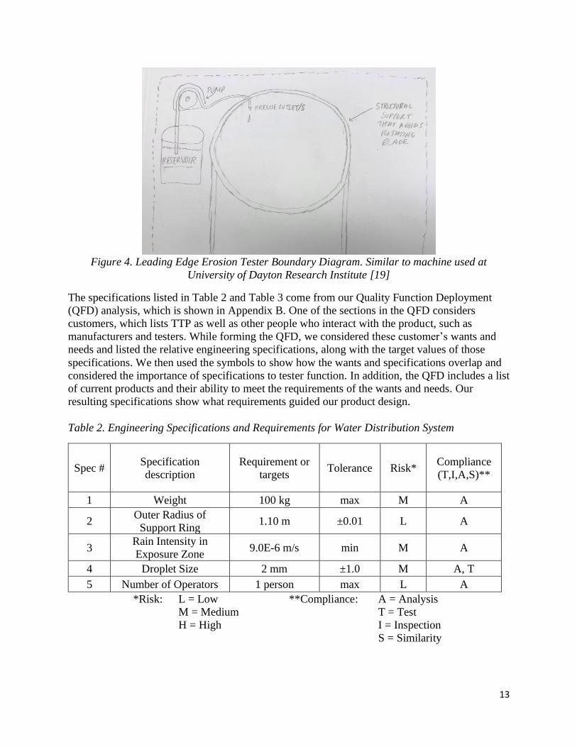
The boundary diagram in Figure 4 conveys the specific goals we aimed to achieve for our final
design. Main components of our final design include a motor, three DU 96-W-180 airfoil-shaped
arms, sample attachment zones, water droppers, and a transparent covering. The resulting
material and component selection will be primarily driven by our $1,000 budget, blade tip speed
requirement of 100 m/s, and single operator goals.
13
Figure 4. Leading Edge Erosion Tester Boundary Diagram. Similar to machine used at
University of Dayton Research Institute [19]
The specifications listed in Table 2 and Table 3 come from our Quality Function Deployment
(QFD) analysis, which is shown in Appendix B. One of the sections in the QFD considers
customers, which lists TTP as well as other people who interact with the product, such as
manufacturers and testers. While forming the QFD, we considered these customer’s wants and
needs and listed the relative engineering specifications, along with the target values of those
specifications. We then used the symbols to show how the wants and specifications overlap and
considered the importance of specifications to tester function. In addition, the QFD includes a list
of current products and their ability to meet the requirements of the wants and needs. Our
resulting specifications show what requirements guided our product design.
Table 2. Engineering Specifications and Requirements for Water Distribution System
Spec # Specification
description
Requirement or
targets Tolerance Risk*
Compliance
(T,I,A,S)**
1 Weight 100 kg max M A
2 Outer Radius of
Support Ring 1.10 m ±0.01 L A
3 Rain Intensity in
Exposure Zone 9.0E-6 m/s min M A
4 Droplet Size 2 mm ±1.0 M A, T
5 Number of Operators 1 person max L A
*Risk: L = Low **Compliance: A = Analysis
M = Medium T = Test
H = High I = Inspection
S = Similarity
14
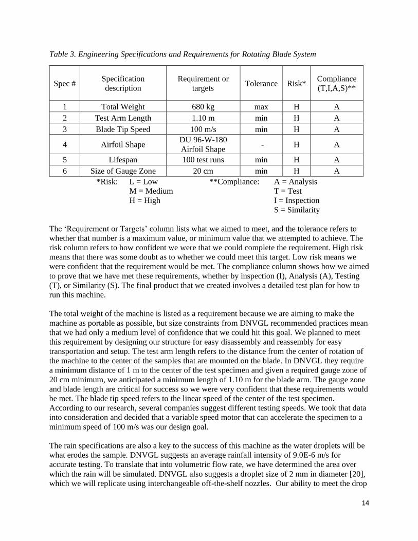
Table 3. Engineering Specifications and Requirements for Rotating Blade System
Spec # Specification
description
Requirement or
targets Tolerance Risk*
Compliance
(T,I,A,S)**
1 Total Weight 680 kg max H A
2 Test Arm Length 1.10 m min H A
3 Blade Tip Speed 100 m/s min H A
4 Airfoil Shape DU 96-W-180
Airfoil Shape - H A
5 Lifespan 100 test runs min H A
6 Size of Gauge Zone 20 cm min H A
*Risk: L = Low **Compliance: A = Analysis
M = Medium T = Test
H = High I = Inspection
S = Similarity
The ‘Requirement or Targets’ column lists what we aimed to meet, and the tolerance refers to
whether that number is a maximum value, or minimum value that we attempted to achieve. The
risk column refers to how confident we were that we could complete the requirement. High risk
means that there was some doubt as to whether we could meet this target. Low risk means we
were confident that the requirement would be met. The compliance column shows how we aimed
to prove that we have met these requirements, whether by inspection (I), Analysis (A), Testing
(T), or Similarity (S). The final product that we created involves a detailed test plan for how to
run this machine.
The total weight of the machine is listed as a requirement because we are aiming to make the
machine as portable as possible, but size constraints from DNVGL recommended practices mean
that we had only a medium level of confidence that we could hit this goal. We planned to meet
this requirement by designing our structure for easy disassembly and reassembly for easy
transportation and setup. The test arm length refers to the distance from the center of rotation of
the machine to the center of the samples that are mounted on the blade. In DNVGL they require
a minimum distance of 1 m to the center of the test specimen and given a required gauge zone of
20 cm minimum, we anticipated a minimum length of 1.10 m for the blade arm. The gauge zone
and blade length are critical for success so we were very confident that these requirements would
be met. The blade tip speed refers to the linear speed of the center of the test specimen.
According to our research, several companies suggest different testing speeds. We took that data
into consideration and decided that a variable speed motor that can accelerate the specimen to a
minimum speed of 100 m/s was our design goal.
The rain specifications are also a key to the success of this machine as the water droplets will be
what erodes the sample. DNVGL suggests an average rainfall intensity of 9.0E-6 m/s for
accurate testing. To translate that into volumetric flow rate, we have determined the area over
which the rain will be simulated. DNVGL also suggests a droplet size of 2 mm in diameter [20],
which we will replicate using interchangeable off-the-shelf nozzles. Our ability to meet the drop

15
size and frequency specifications was validated using a simple scale and the assumption that the
falling drops are spherical. We report drop variability statistics such as mean diameter and
standard deviation. In order to replicate conditions that wind turbines experience, DNVGL
suggests having climate control so that the temperature of the unit stays between 20 – 25 ℃, and
humidity ranges from 20 – 90 % relative humidity. We plan to meet this requirement by
recommending our system be used in rooms or environments that match the specification
description. The shape of the blade is specified as ‘Aerofoil shaped’ by DNVGL, and after
speaking to TTP, we have decided that a DU 96-W-180 airfoil shape will best represent wind
turbines from today’s market. The highest risk specification is the reliability and longevity of our
machine. We want the unit to work safely and effectively for 100 test runs. This is a high-risk
specification because different tests may run for different amounts of time, so overall run-time is
difficult to predict. Data from other testing units suggest that a single test could take anywhere
from 10 – 85 consecutive hours to complete. If we were to assume the longest operating case,
then our machine would be running for 8500 hours to complete 100 test runs. This is almost a
year of total operating time. Since the final product will be going through many operation cycles
in its lifetime, we focused on cyclic loading and fatigue in our designs. We also performed finite
element analysis to complement the cyclic loading calculations.
4. Concept Design
While working on our concept design we took inspiration from leaders in the field of design like
the Stanford Design School and IDEO. With their methods of creating innovative solutions we
aspired to come up with solutions to our own problems. One of the ways both design maestros
come up with their ideas is by brainstorming solutions for completing specific functions and
promoting play. In an attempt to replicate this, we played games and got into the creative spirit
with all ideas for solutions to function performance encouraged, no matter how impractical or
outright ludicrous. These ideas might spawn additional, more realistic ideas. The functions we
began brainstorming ideas for were creating droplets, measuring erosion rate, and supplying
fluid. We chose to specifically pursue brainstorming solutions to these functions because they are
the most important to the success of our system. Pictures of the models we constructed based on
the brainstormed ideas are shown in Appendix K. These constructed models were among the
most hopeful from our brainstorming sessions. By building them we were able to better assess
their potential to meet our design specifications. After these brainstorming sessions we went to
the toy chest and attempted to build our best ideas so that we could see if they were feasible.
Once we had our ideas and determined which ones could work, we went forward with a more in-
depth process to select the best possible design.
4.1 Design Selection Process
In order to help us eliminate some ideas and develop more effective ones, we utilized Pugh
matrices. The Pugh Matrices allowed us to evaluate which combinations of our different function
ideas would create better overall systems. Our Pugh matrices for supporting water delivery
system and creating water droplets are shown in Appendix D. In the Pugh matrix for supporting
the water delivery system, we used a straight leg support system as the datum and compared
arched legs, cylinder base, telescoping legs, wheeled legs, and hydraulic shocks. The criteria we
used for comparisons were stability, portability, safety, ability to integrate, and height change.
16
After analyzing our ideas against the datum using these criteria, it was evident that the hydraulic
shocks were the best alternative for supporting the water delivery system. The next function we
analyzed using a Pugh matrix was creating water droplets. We used an eyedropper as the datum
and compared it to a peristaltic pump, filter, pressure driven dropper tube, and syringes driven by
a lead screw, rack and pinion, or belt. The criteria we used was weight, cost, length of continuous
operation time, safety, ease of achieving specified rainfall intensity, 2 mm raindrops, and
constant flow rate. The peristaltic pump paired with blunt tipped hypodermic needles with
specified diameters was the clear winner because it outperformed the water dropper in more
criteria than any other idea. Although we created a Pugh matrix for dampening vibrations, we
will not use a vibration dampening component in the water delivery system because TTP
suggested that the dampening mechanism be a part of the rotating blade system.
We used the results of the Pugh matrices for each function to create the morphological matrix,
which is shown in Appendix E. Our morphological matrix took the best 5 concepts for each of
our functions and combined the most compatible functions to create 5 different concepts
systems. It is important to note that after speaking TTP, we decided that all concept systems
would use nozzles for the create water droplet function. Next, we took the resulting 5 systems
from our morphological matrix and compared them using a weighted-decision matrix that can be
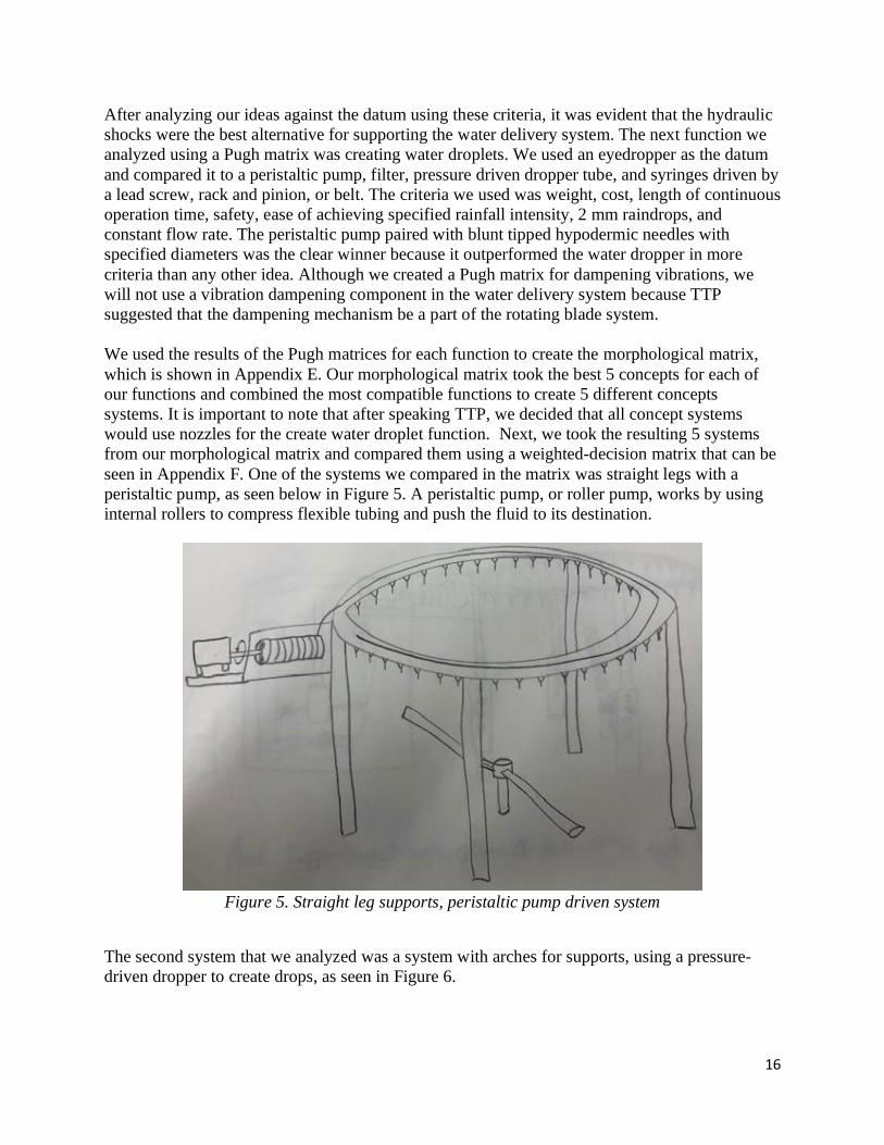
seen in Appendix F. One of the systems we compared in the matrix was straight legs with a
peristaltic pump, as seen below in Figure 5. A peristaltic pump, or roller pump, works by using
internal rollers to compress flexible tubing and push the fluid to its destination.
Figure 5. Straight leg supports, peristaltic pump driven system
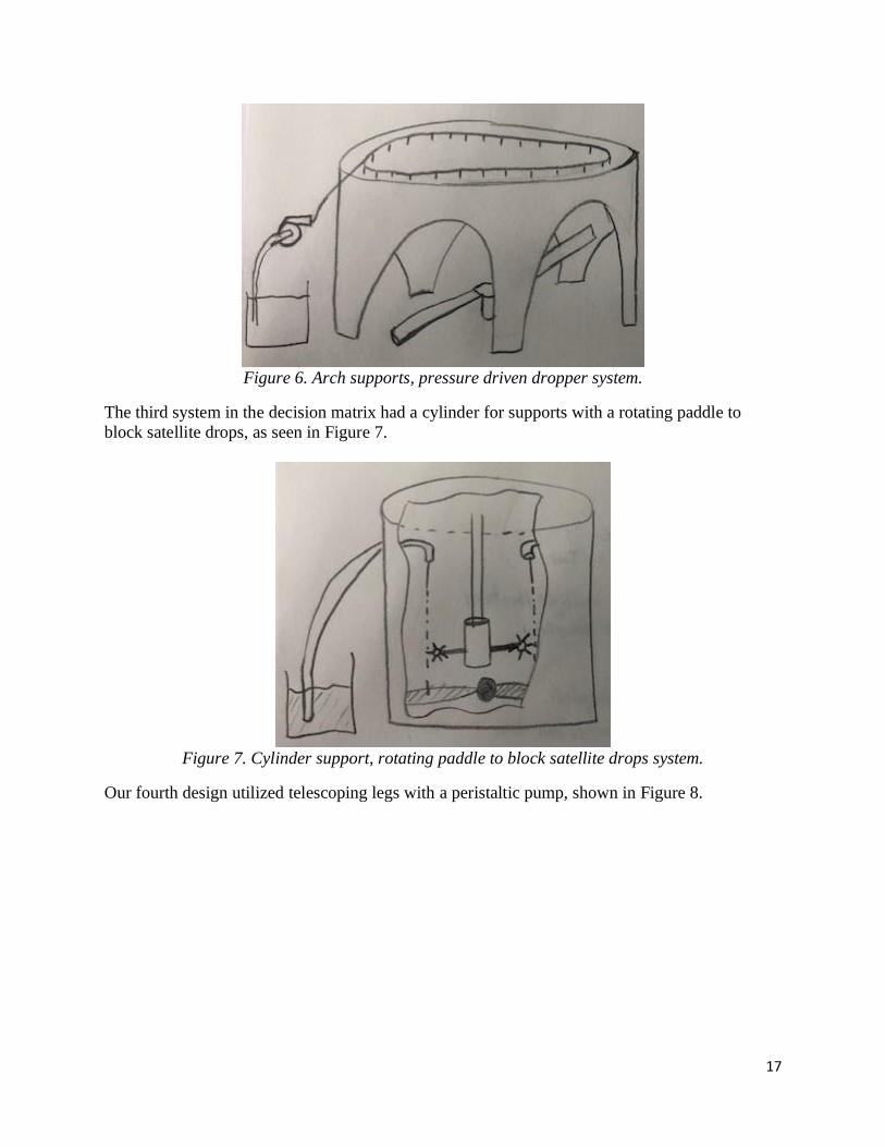
The second system that we analyzed was a system with arches for supports, using a pressure-
driven dropper to create drops, as seen in Figure 6.
17
Figure 6. Arch supports, pressure driven dropper system.
The third system in the decision matrix had a cylinder for supports with a rotating paddle to
block satellite drops, as seen in Figure 7.
Figure 7. Cylinder support, rotating paddle to block satellite drops system.
Our fourth design utilized telescoping legs with a peristaltic pump, shown in Figure 8.

18
Figure 8. Telescoping leg supports, peristaltic pump driven system
The fifth and final system had wheeled legs and used a pressure driven dropper, as can be seen in
Figure 9.
Figure 9. Wheeled leg supports, pressure driven dropper system
After applying a weight of importance to each criterion, we found that the simple straight legs
with a peristaltic pump scored the best, which is why we are going forward with this design.
Our design for the water delivery system utilizes peristaltic pumps to deliver necessary
volumetric flowrates to droppers of specific nozzle size. Our peristaltic pumps provide consistent
flowrates for long periods of time, and the nozzles can deliver precise water droplet sizes to
19
specific locations. When paired, this equipment provides reliable and repeatable droplet delivery.
We arrived at this design after using ideating methods such as brainstorming and brainwriting to
create as many solution ideas as possible. Then we experimented with many ideas to find the
most accurate and consistent droplet formation methods. According to our design criteria, the 3D
printed peristaltic pumps performed far better than our other ideas for water delivery. A complete
list of our ideas is in Appendix C.
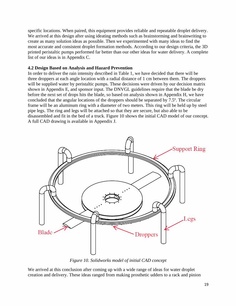
4.2 Design Based on Analysis and Hazard Prevention
In order to deliver the rain intensity described in Table 1, we have decided that there will be
three droppers at each angle location with a radial distance of 1 cm between them. The droppers
will be supplied water by peristaltic pumps. These decisions were driven by our decision matrix
shown in Appendix E, and sponsor input. The DNVGL guidelines require that the blade be dry
before the next set of drops hits the blade, so based on analysis shown in Appendix H, we have
concluded that the angular locations of the droppers should be separated by 7.5º. The circular
frame will be an aluminum ring with a diameter of two meters. This ring will be held up by steel
pipe legs. The ring and legs will be attached so that they are secure, but also able to be
disassembled and fit in the bed of a truck. Figure 10 shows the initial CAD model of our concept.
A full CAD drawing is available in Appendix J.
Figure 10. Solidworks model of initial CAD concept
We arrived at this conclusion after coming up with a wide range of ideas for water droplet
creation and delivery. These ideas ranged from making prosthetic udders to a rack and pinion

20
driven dropper. We created a concept model prototype help explain our concept model designs
visually. This model showcases the concepts we chose for the structural and water droplet
delivery systems. An image of this concept model is shown in Figure 11.
Figure 11. Concept model prototype
Figure 12. CAD model of a peristaltic pump

21
While testing this concept model we were able to determine which factors of the design were
successful and which needed more attention. The structure and dropper system proved to be
successful concepts. The structure was strong and stable, and the droppers delivered consistent
drop sizes at specific locations. The location of the motor mount showed need for more attention.
Operating the pump motor while it is mounted to the support structure allows vibrations from the
motor to transfer into the structure. To avoid vibrations in the structure holding the nozzles we
will separate the pump motor from the structure and keep the tubing connection from the pump
to the nozzles. Due to the preliminary analysis that we have done, we are reasonably confident
that our design can deliver the desired performance. With this desired performance there are
inherent hazards. Since we shall be manufacturing the water delivery system, we shall remain
focused on the hazards of that particular system, but for a full list of hazards and the way we
would attempt to combat them, see the Hazard Checklist in Appendix G. The main hazards of the
water delivery system involve getting water into electrical systems or potentially flooding the
room in which the machine is operating.
5. Final Design
Our final design for our blade coating erosion testing machine is made up of two systems. These
systems are the Fluid Delivery System and the Rotating Blade System. Figure 13 shows an
isometric view of our design in SolidWorks. Next, we go over the two systems and the main
components of each system.
Figure 13. CAD assembly drawing
22
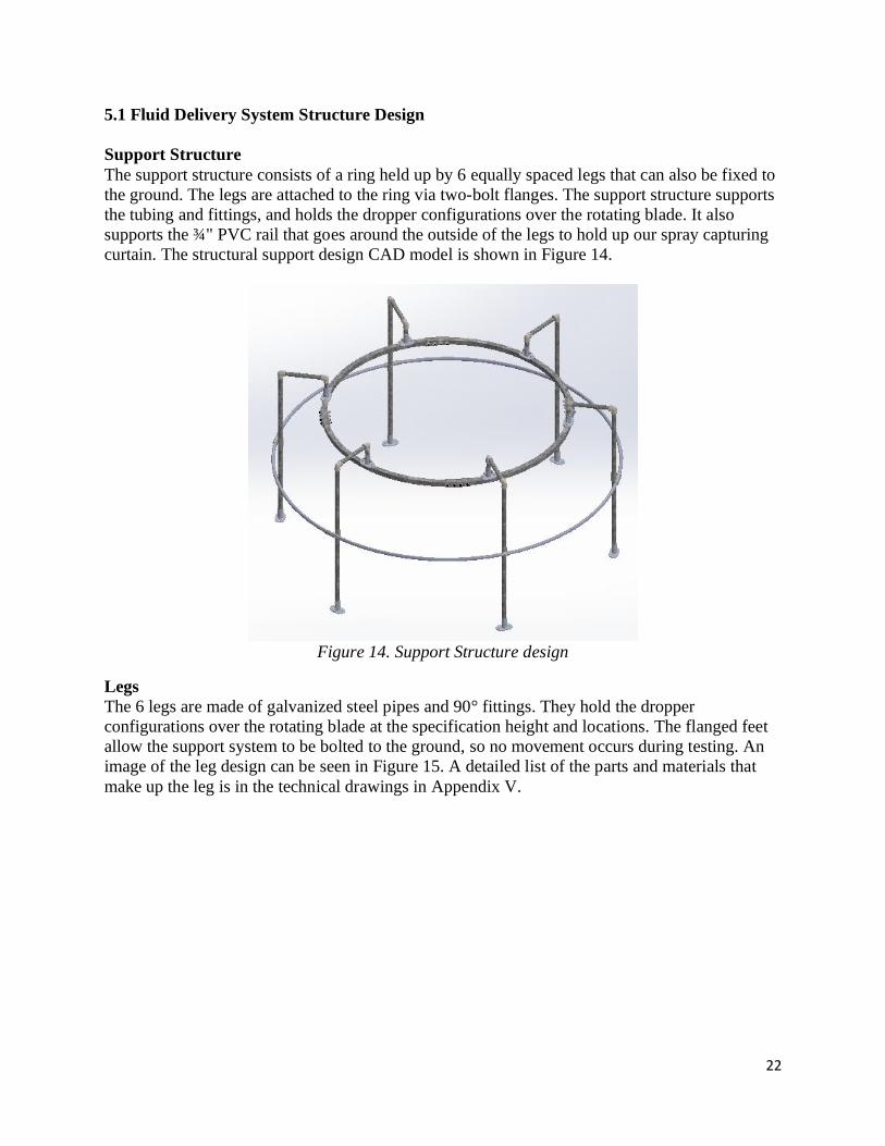
5.1 Fluid Delivery System Structure Design
Support Structure
The support structure consists of a ring held up by 6 equally spaced legs that can also be fixed to
the ground. The legs are attached to the ring via two-bolt flanges. The support structure supports
the tubing and fittings, and holds the dropper configurations over the rotating blade. It also
supports the ¾" PVC rail that goes around the outside of the legs to hold up our spray capturing
curtain. The structural support design CAD model is shown in Figure 14.
Figure 14. Support Structure design
Legs
The 6 legs are made of galvanized steel pipes and 90° fittings. They hold the dropper
configurations over the rotating blade at the specification height and locations. The flanged feet
allow the support system to be bolted to the ground, so no movement occurs during testing. An
image of the leg design can be seen in Figure 15. A detailed list of the parts and materials that
make up the leg is in the technical drawings in Appendix V.

23
Figure 15. Leg design for structural support
We performed FEA on the legs to ensure they can handle design loads. We used a conservative
load estimate of 50lbf load on each of the legs. The result of the study shows little deflection and
acceptable stresses on the legs. Below, in Figure 16 and 17, are snapshots of the results of our
study.
Figure 16. Crude leg FEA with conservative 50lbf load per leg
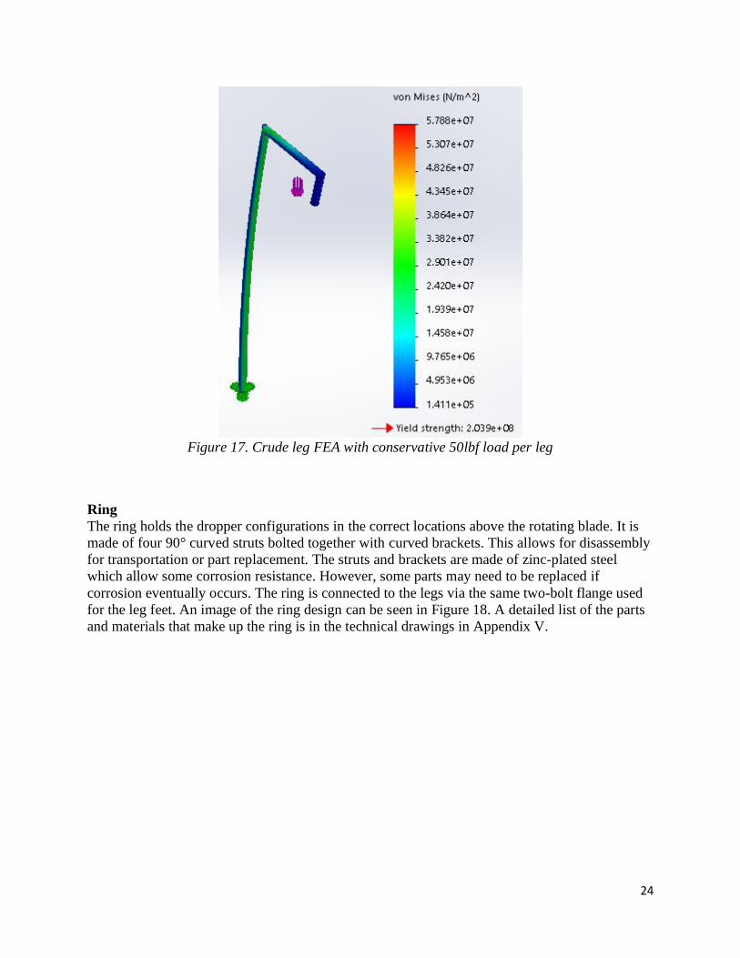
24
Figure 17. Crude leg FEA with conservative 50lbf load per leg
Ring
The ring holds the dropper configurations in the correct locations above the rotating blade. It is
made of four 90° curved struts bolted together with curved brackets. This allows for disassembly
for transportation or part replacement. The struts and brackets are made of zinc-plated steel
which allow some corrosion resistance. However, some parts may need to be replaced if
corrosion eventually occurs. The ring is connected to the legs via the same two-bolt flange used
for the leg feet. An image of the ring design can be seen in Figure 18. A detailed list of the parts
and materials that make up the ring is in the technical drawings in Appendix V.

25
Figure 18. Support ring dimensions
We performed FEA on the ring to ensure it can handle design loads. We used a conservative load
estimate of 200lbf load on the ring. The result of the study shows little deflection and acceptable
stresses on the ring. Below in Figures 19 and 20 are snapshots of the results of our study.
Figure 19. Crude Ring FEA with conservative 200lbf load

26
Figure 20. Crude Ring FEA with conservative 200lbf load
Table 4. Summary of results from Crude Structural FEA
Max. Deflection
Normal Conditions (mm)
Max. Stress Normal Conditions
(MPa)
Yield Strength (MPa)
Factor of Safety
Ring 0.052 25.1 204 8.13
Leg 8.4 57.9 204 3.52
5.2 Fluid Path Design
We have chosen to use a peristaltic pump, as shown in Figure 21, to move the fluid throughout
the fluid delivery system. The pump works by squeezing the tubing as the roller rotates. This
pump is a positive displacement pump and it will work by drawing fluid from our reservoir and
pumping that fluid at a constant flow rate to the nozzles. The pump depicted was specifically
selected because it has variable speed capability, it has an adequate pressure rating, and it meets
our design flow rate requirement.
Figure 21. Peristaltic pump and inside view
27
The pump draws fluid through a hole in the wall of the reservoir, then through ¼" flexible tubing
and an in-line filter. The filter is shown in Figure 22.
Figure 22. In-line tubing filter
The ¼" tubing is connected to the inlet of the pump with s barbed reducer fitting as shown in
Figure 23.
Figure 23. Barbed reducer tubing fitting
The outlet of the pump is connected with another barbed reducer fitting to another length of ¼"
tubing. This tubing is routed up the nearest leg to the top face of the ring assembly. There, it
splits into two, and then four lengths of ¼" flexible tubing with 3 total barbed Y-connectors. The
barbed Y-connectors are shown in Figure 24.
Figure 24. Barbed Y-connector
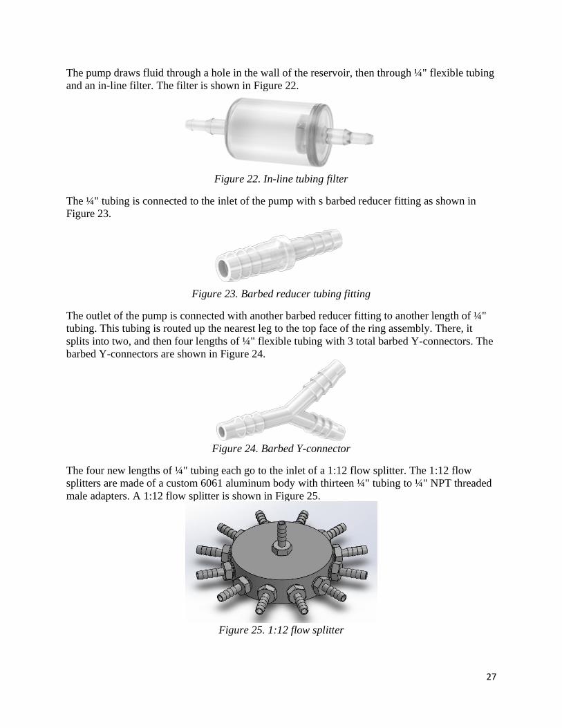
The four new lengths of ¼" tubing each go to the inlet of a 1:12 flow splitter. The 1:12 flow
splitters are made of a custom 6061 aluminum body with thirteen ¼" tubing to ¼" NPT threaded
male adapters. A 1:12 flow splitter is shown in Figure 25.
Figure 25. 1:12 flow splitter
28
These adapters allow ¼" tubing to attach to the 1:12 splitter body. The inlet of the 1:12 flow
splitter is on the top face of the body. In the design, flow from the inlet ¼" tubing enters the body
and splits evenly 12 ways before exiting each of the 12 outlet ¼" tubing lengths. Each of these
outlet ¼" tubing lengths routes to a dropper configuration assembly.
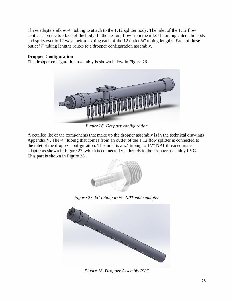
Dropper Configuration
The dropper configuration assembly is shown below in Figure 26.
Figure 26. Dropper configuration
A detailed list of the components that make up the dropper assembly is in the technical drawings
Appendix V. The ¼" tubing that comes from an outlet of the 1:12 flow splitter is connected to
the inlet of the dropper configuration. This inlet is a ¼" tubing to 1/2" NPT threaded male
adapter as shown in Figure 27, which is connected via threads to the dropper assembly PVC.
This part is shown in Figure 28.
Figure 27. ¼" tubing to ½" NPT male adapter
Figure 28. Dropper Assembly PVC

29
The dropper assembly PVC has a PVC end cap to prevent flow from escaping the end of the
pipe. The dropper assembly PVC also has 20 threaded holes in line along its length. Each of
these holes will be joined via threads with a thread to luer lock adapter as shown in Figure 29.
Figure 29. Thread-to-luer lock adapter
These adapters allow a connection from the PVC pipe to our nozzles. A nozzle is shown in
Figure 30.
Figure 30. 32 Ga nozzle
The nozzles are fit on the end of the adapters via luer lock connections.
The dropper configurations are held in place along the ring with a pipe clamp connection. The
components of this connection are detailed in the technical drawing package in Appendix V.
This clamp connection is shown in Figure 31.

30
Figure 31. Dropper clamp connection
The clamp has holes in it where the dropper nozzles fit into the clamp. The center clamp hole has
the 4th dropper nozzle from the inlet side of the dropper PVC going through it. This ensures
vertical alignment between the droppers and the exposure zone of the rotating blade system.
Spray Collection Curtains
The spray collection curtains will hang from the ¾" PVC rail that is connected to the outside of
the legs with through-hole reducers as shown in Figure 32.
Figure 32. PVC rail
The PVC rail is made up of three lengths of ¾" schedule 40 PVC pipe. For assembly, each of
these lengths are fed through a through-hole reducer and flexed to fit into the through hole
reducer on a neighboring leg. Once each ¾" PVC pipe is held by two through-hole reducers, the
ends of the PVC pipes are connected with ¾" PVC fittings to create a circular rail. The four
waterproof curtains are clipped onto the PVC rail with the designated clips and grommet holes.
The curtains are pulled tight and connected to the inside face of the outer wall of the reservoir
with plastic rivets. This allows captured spray from droplet impacts to be funneled into the
reservoir. The curtains can be trimmed along the bottom to eliminate extra length.

31
5.3 Reservoir Design
The reservoir holds the water that has been captured from falling drops and supplies that water
back to the peristaltic pump. The reservoir also has holes around the top of the walls for the
spray curtains to be attached with plastic rivets. An image of the reservoir assembly is shown in
Figure 33.
Figure 33. Reservoir
We believe that a plastic pool or tank with similar dimensions would be a good starting point for
manufacturing this component. We were unable to find a pool or tank that fit the cost and
geometric criteria for this project during the time we had available. Therefore, we did not select a
stock part or raw materials to construct the reservoir from. Once a stock part is obtained, we
recommend using stiff plastic sheeting and caulk to create a water-tight wall along the inside
diameter of the reservoir.
5.4 Rotating Blade System
The Rotating Blade System seen below in Figure 34 consists of four main components, the disk,
the blades, the sheaths, and the motor. We made the decision to have a large central disk as a
mounting port for both safety and rotor balance reasons. The larger the disk, the smaller the
blades need to be which decreases the chance that they are going to fly out of their mounts. And
one of the most easily balanced rotating objects is a circular disk.

32
Figure 34. Rotating Blade System
We needed a secure method to spin three sizable aluminum airfoil blades as seen in Figure 35 up
to 100 m/s, so we needed to design a system that had very secure connections. Large tabs at the
mounting side of the blade allows for easy alignment and for four 30 mm diameter bolts to attach
each blade to the disk.
Figure 35. DU 96-W-180 6061 aluminum airfoil blade
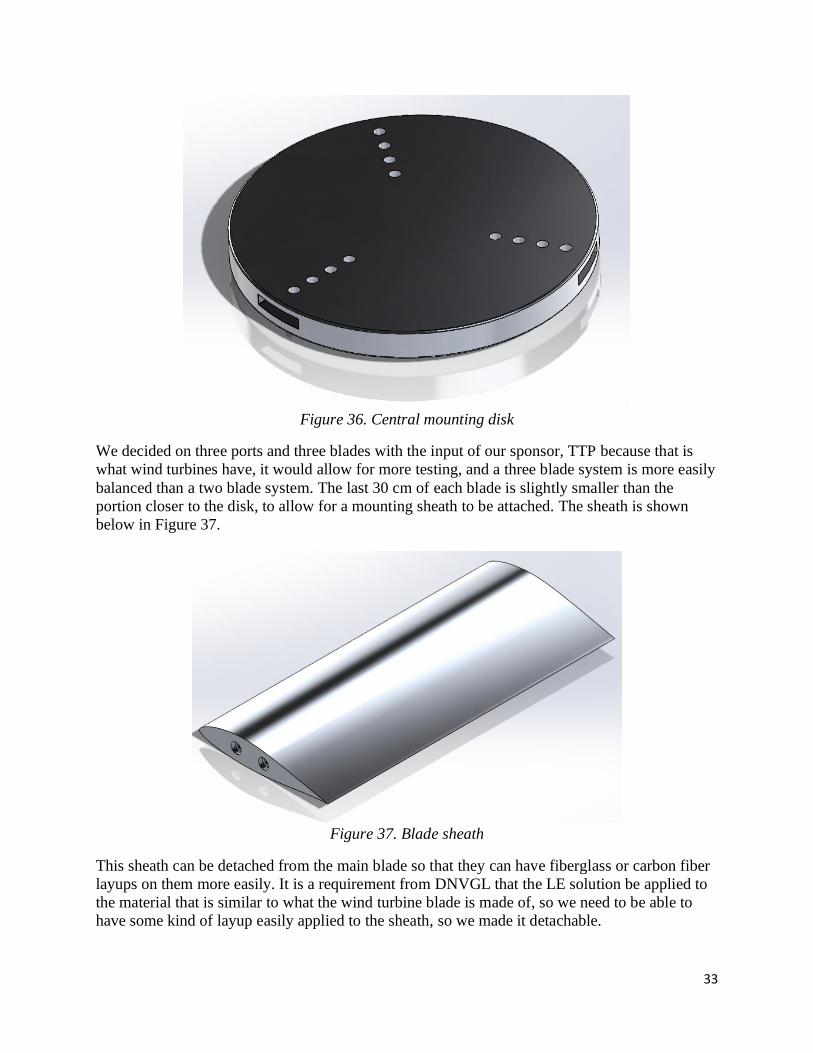
Those mounting locations line up with holes in the central disk 36, which has three ports spaced
120° from each other. The disk is shown below in Figure 36.
33
Figure 36. Central mounting disk
We decided on three ports and three blades with the input of our sponsor, TTP because that is
what wind turbines have, it would allow for more testing, and a three blade system is more easily
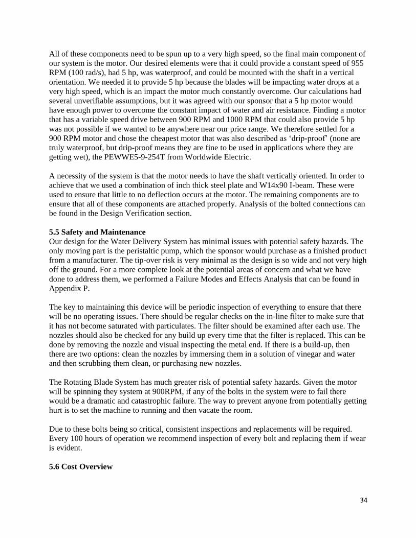
balanced than a two blade system. The last 30 cm of each blade is slightly smaller than the
portion closer to the disk, to allow for a mounting sheath to be attached. The sheath is shown
below in Figure 37.
Figure 37. Blade sheath
This sheath can be detached from the main blade so that they can have fiberglass or carbon fiber
layups on them more easily. It is a requirement from DNVGL that the LE solution be applied to
the material that is similar to what the wind turbine blade is made of, so we need to be able to
have some kind of layup easily applied to the sheath, so we made it detachable.
34
All of these components need to be spun up to a very high speed, so the final main component of
our system is the motor. Our desired elements were that it could provide a constant speed of 955
RPM (100 rad/s), had 5 hp, was waterproof, and could be mounted with the shaft in a vertical
orientation. We needed it to provide 5 hp because the blades will be impacting water drops at a
very high speed, which is an impact the motor much constantly overcome. Our calculations had
several unverifiable assumptions, but it was agreed with our sponsor that a 5 hp motor would
have enough power to overcome the constant impact of water and air resistance. Finding a motor
that has a variable speed drive between 900 RPM and 1000 RPM that could also provide 5 hp
was not possible if we wanted to be anywhere near our price range. We therefore settled for a
900 RPM motor and chose the cheapest motor that was also described as ‘drip-proof’ (none are
truly waterproof, but drip-proof means they are fine to be used in applications where they are
getting wet), the PEWWE5-9-254T from Worldwide Electric.
A necessity of the system is that the motor needs to have the shaft vertically oriented. In order to
achieve that we used a combination of inch thick steel plate and W14x90 I-beam. These were
used to ensure that little to no deflection occurs at the motor. The remaining components are to
ensure that all of these components are attached properly. Analysis of the bolted connections can
be found in the Design Verification section.
5.5 Safety and Maintenance
Our design for the Water Delivery System has minimal issues with potential safety hazards. The
only moving part is the peristaltic pump, which the sponsor would purchase as a finished product
from a manufacturer. The tip-over risk is very minimal as the design is so wide and not very high
off the ground. For a more complete look at the potential areas of concern and what we have
done to address them, we performed a Failure Modes and Effects Analysis that can be found in
Appendix P.
The key to maintaining this device will be periodic inspection of everything to ensure that there
will be no operating issues. There should be regular checks on the in-line filter to make sure that
it has not become saturated with particulates. The filter should be examined after each use. The
nozzles should also be checked for any build up every time that the filter is replaced. This can be
done by removing the nozzle and visual inspecting the metal end. If there is a build-up, then
there are two options: clean the nozzles by immersing them in a solution of vinegar and water
and then scrubbing them clean, or purchasing new nozzles.
The Rotating Blade System has much greater risk of potential safety hazards. Given the motor
will be spinning they system at 900RPM, if any of the bolts in the system were to fail there
would be a dramatic and catastrophic failure. The way to prevent anyone from potentially getting
hurt is to set the machine to running and then vacate the room.
Due to these bolts being so critical, consistent inspections and replacements will be required.
Every 100 hours of operation we recommend inspection of every bolt and replacing them if wear
is evident.
5.6 Cost Overview
35
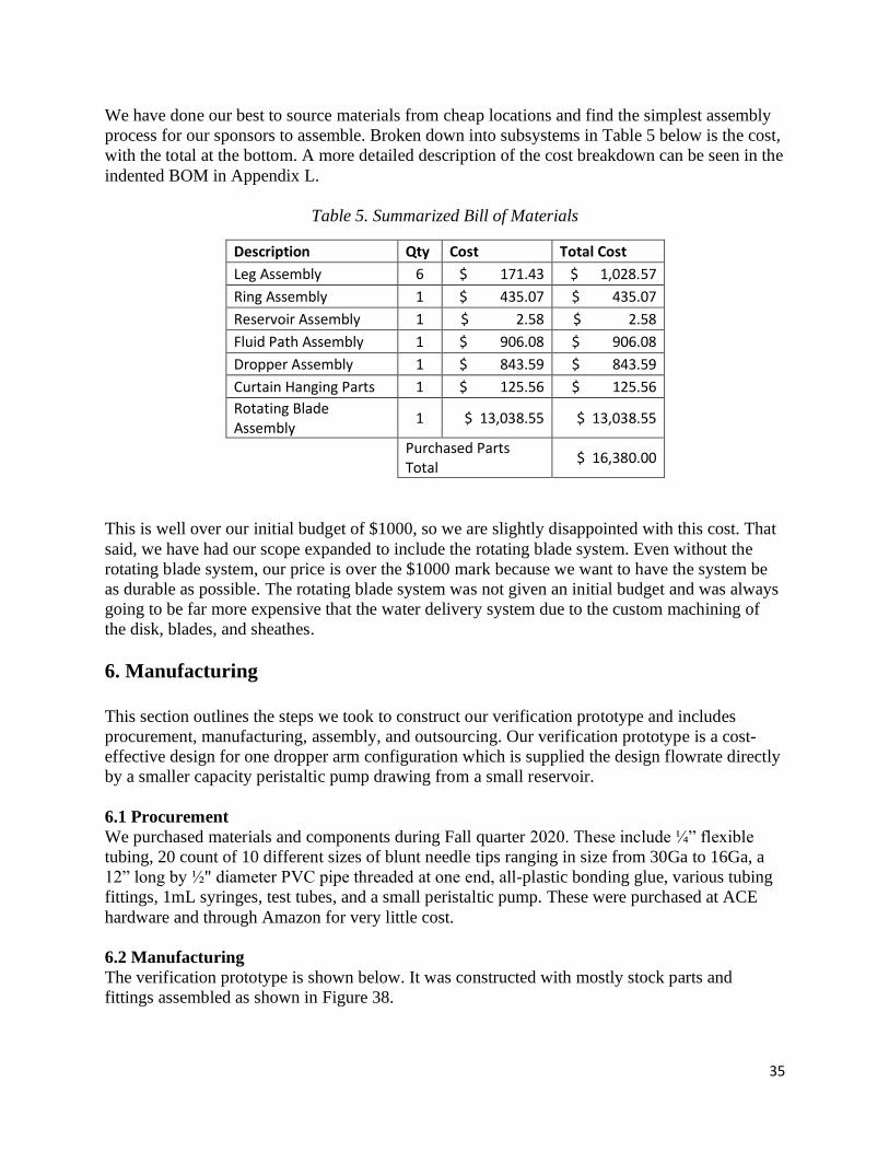
We have done our best to source materials from cheap locations and find the simplest assembly
process for our sponsors to assemble. Broken down into subsystems in Table 5 below is the cost,
with the total at the bottom. A more detailed description of the cost breakdown can be seen in the
indented BOM in Appendix L.
Table 5. Summarized Bill of Materials
Description Qty Cost Total Cost
Leg Assembly 6 $ 171.43 $ 1,028.57
Ring Assembly 1 $ 435.07 $ 435.07
Reservoir Assembly 1 $ 2.58 $ 2.58
Fluid Path Assembly 1 $ 906.08 $ 906.08
Dropper Assembly 1 $ 843.59 $ 843.59
Curtain Hanging Parts 1 $ 125.56 $ 125.56
Rotating Blade Assembly
1 $ 13,038.55 $ 13,038.55
Purchased Parts Total
$ 16,380.00
This is well over our initial budget of $1000, so we are slightly disappointed with this cost. That
said, we have had our scope expanded to include the rotating blade system. Even without the
rotating blade system, our price is over the $1000 mark because we want to have the system be
as durable as possible. The rotating blade system was not given an initial budget and was always
going to be far more expensive that the water delivery system due to the custom machining of
the disk, blades, and sheathes.
6. Manufacturing
This section outlines the steps we took to construct our verification prototype and includes
procurement, manufacturing, assembly, and outsourcing. Our verification prototype is a cost-
effective design for one dropper arm configuration which is supplied the design flowrate directly
by a smaller capacity peristaltic pump drawing from a small reservoir.
6.1 Procurement
We purchased materials and components during Fall quarter 2020. These include ¼” flexible
tubing, 20 count of 10 different sizes of blunt needle tips ranging in size from 30Ga to 16Ga, a
12” long by ½" diameter PVC pipe threaded at one end, all-plastic bonding glue, various tubing
fittings, 1mL syringes, test tubes, and a small peristaltic pump. These were purchased at ACE
hardware and through Amazon for very little cost.
6.2 Manufacturing
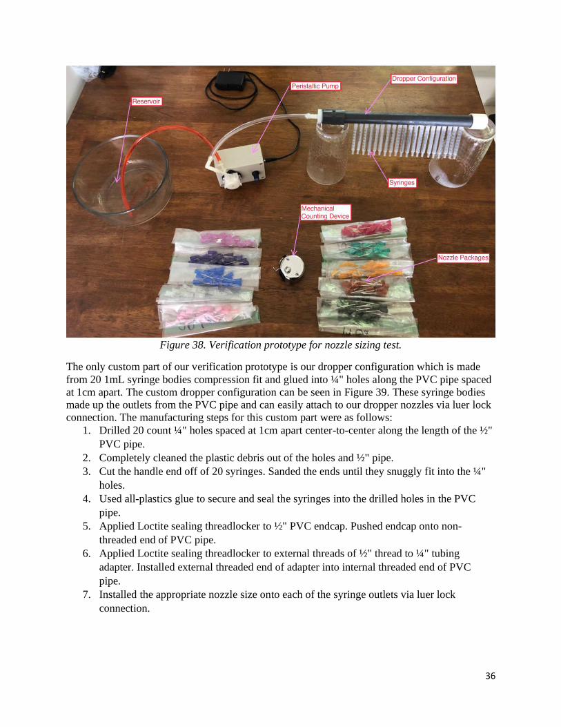
The verification prototype is shown below. It was constructed with mostly stock parts and
fittings assembled as shown in Figure 38.
36
Figure 38. Verification prototype for nozzle sizing test.
The only custom part of our verification prototype is our dropper configuration which is made
from 20 1mL syringe bodies compression fit and glued into ¼" holes along the PVC pipe spaced
at 1cm apart. The custom dropper configuration can be seen in Figure 39. These syringe bodies
made up the outlets from the PVC pipe and can easily attach to our dropper nozzles via luer lock
connection. The manufacturing steps for this custom part were as follows:
1. Drilled 20 count ¼" holes spaced at 1cm apart center-to-center along the length of the ½"
PVC pipe.
2. Completely cleaned the plastic debris out of the holes and ½" pipe.
3. Cut the handle end off of 20 syringes. Sanded the ends until they snuggly fit into the ¼"
holes.
4. Used all-plastics glue to secure and seal the syringes into the drilled holes in the PVC
pipe.
5. Applied Loctite sealing threadlocker to ½" PVC endcap. Pushed endcap onto non-
threaded end of PVC pipe.
6. Applied Loctite sealing threadlocker to external threads of ½" thread to ¼" tubing
adapter. Installed external threaded end of adapter into internal threaded end of PVC
pipe.
7. Installed the appropriate nozzle size onto each of the syringe outlets via luer lock
connection.

37
Figure 39. Custom dropper configuration.
Our verification prototype worked for our testing purposes, but it is not capable of handling the
longevity demanded by our final design specifications. The parts and manufacturing of the final
dropper configuration assembly will be described with the rest of the custom parts we designed
in our Final Design section.
6.3 Assembly
Our verification prototype is a system that moves water from a small reservoir via a peristaltic
pump to the manufactured dropper assembly, out the nozzles, and into collection test tubes. The
assembly steps for our verification prototype were as follows:
1. Filled a large bowl with water. This was the reservoir for the verification prototype.
2. Connected the inlet tube of the peristaltic pump to one end of the short flexible 1/8"
tubing piece with a straight fitting.
3. Submerged the other end of the short flexible 1/8" tubing piece into the bowl.
4. Connected the outlet tube of the peristaltic pump to one end of the long flexible ¼"
tubing piece with a 1/8” to ¼" expander fitting.
5. Connected the other end of the long flexible ¼" tubing piece to the ¼" tubing fitting end
of the thread to tubing adapter on the custom dropper configuration.
6. Installed the appropriate nozzle size onto each of the syringe outlets via luer lock
connection.
7. Arranged test tubes and collection cups under nozzles. Ensured that test tubes only collect
from one dropper nozzle throughout any tests.
For testing, the peristaltic pump was calibrated to the design flowrate of a single dropper
configuration. During the test, we counted and collected drops from individual nozzles in test
tubes. We were able to take the mass of the fluid collected and solve for the average diameter of
the drops produced. Multiple tests of this experiment with different nozzle sizes allowed us to
develop the curve fit, shown in Figure 41, for drop size produced from our nozzles versus nozzle
diameter and solve for the appropriate nozzle size for our design. Figure 40 below shows the
testing configuration.

38
Figure 40. Experimental setup for drop collection with our verification prototype.
6.4 Outsourcing
We did no outsourcing for producing our prototype. Due to COVID-19, our sponsors requested
that we do not build the final design and instead do design work for the rotating blade system.
All of the manufacturing for the final designs shall be done by TTP. More information about
manufacturing and assembly of the custom components of our design is located in the Final
Design section.
7. Design Verification Chapter
We were able to test our structural prototype to verify the drop size and rainfall intensity design
specifications for our fluid delivery system. We discuss the results of testing in this section,
while the detailed test procedure and data collected during the test can be found in Appendix T
We show that our design meets the remaining specifications through design analysis, mainly
FEA. All of these parameters can be found in our Design Verification Plan in Appendix M.
7.1 Dropper Configuration Verification
The specifications that we were able to test are the production of consistent 2 mm diameter rain
drops from the nozzles, and a total rainfall intensity of 32.5 mm/hr. The test method that we
utilized to verify these specifications included calibrating our peristaltic pump to the design flow
rate for one dropper configuration. This calibrated design flow rate is 1/48th of the total flow rate
necessary to meet our 32.5 mm/hr rainfall intensity across the specification 20 cm exposure zone.
It is 1/48th of the total design flow rate because our structural prototype dropper configuration is
1 of 48 total dropper configurations in our full fluid delivery system design. With the successful
39
operation of one dropper configuration at 1/48th of the total design flow rate, we proved our
prototype’s ability to meet the total rainfall intensity specification of 32.5 mm/hr.
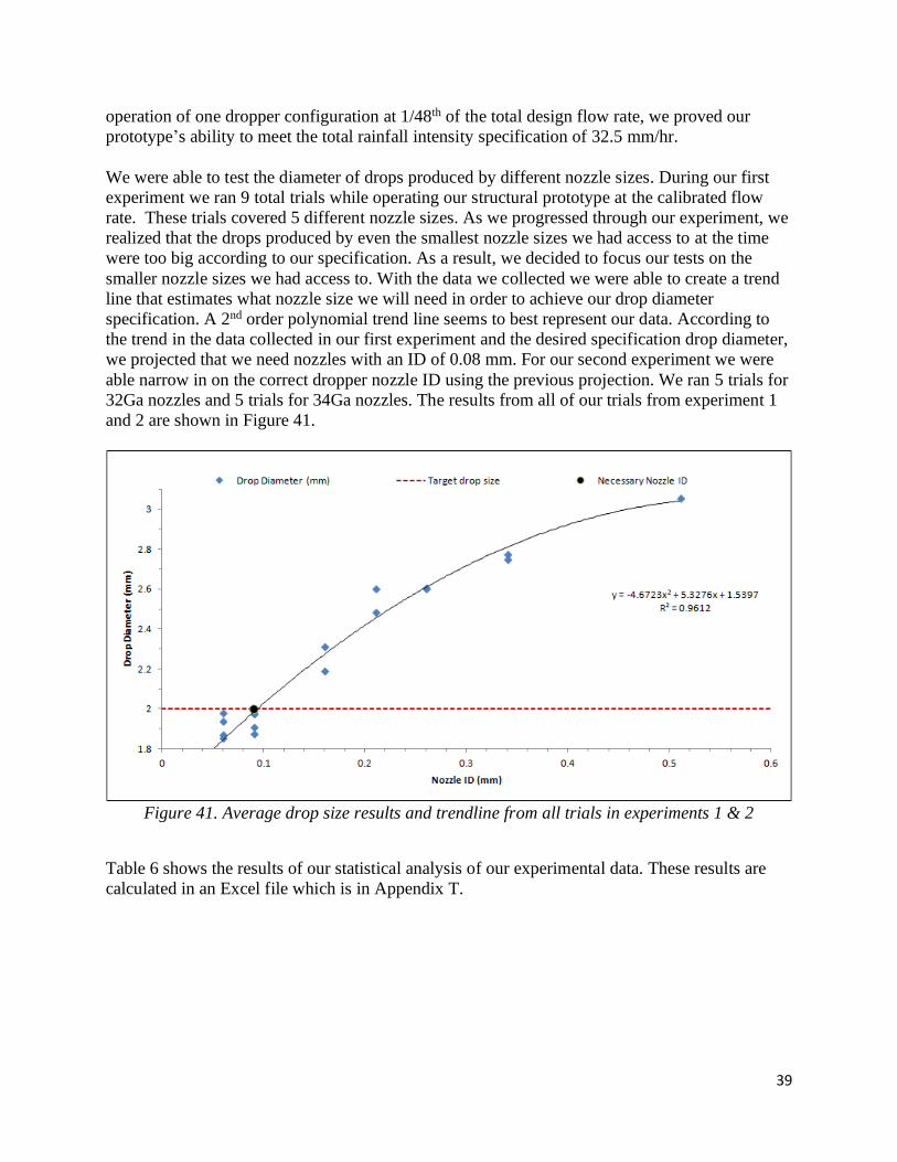
We were able to test the diameter of drops produced by different nozzle sizes. During our first
experiment we ran 9 total trials while operating our structural prototype at the calibrated flow
rate. These trials covered 5 different nozzle sizes. As we progressed through our experiment, we
realized that the drops produced by even the smallest nozzle sizes we had access to at the time
were too big according to our specification. As a result, we decided to focus our tests on the
smaller nozzle sizes we had access to. With the data we collected we were able to create a trend
line that estimates what nozzle size we will need in order to achieve our drop diameter
specification. A 2nd order polynomial trend line seems to best represent our data. According to
the trend in the data collected in our first experiment and the desired specification drop diameter,
we projected that we need nozzles with an ID of 0.08 mm. For our second experiment we were
able narrow in on the correct dropper nozzle ID using the previous projection. We ran 5 trials for
32Ga nozzles and 5 trials for 34Ga nozzles. The results from all of our trials from experiment 1
and 2 are shown in Figure 41.
Figure 41. Average drop size results and trendline from all trials in experiments 1 & 2
Table 6 shows the results of our statistical analysis of our experimental data. These results are
calculated in an Excel file which is in Appendix T.

40
Table 6. Statistical results for each nozzle size
Nozzle Size (Ga)
ID (mm) Drop Diameter (mm)
23 0.34 2.7646 + 0.0831 - 0.0884
25 0.26 2.6058 + 0.0124 - 0.0126
27 0.21 2.5547 + 0.3231 - 0.4359
30 0.16 2.2518 + 0.3344 - 0.4826
32 0.09 1.9412 + 0.0753 - 0.0817
34 0.06 1.8809 + 0.1557 - 0.1869
Due to our relatively few trials with each nozzle size during the first experiment, our
uncertainties in the results for drop diameter produced have large uncertainties when solving for
90% significance. During our first experiment we performed 2 trials per nozzle size for the
23Ga, 25Ga, 27Ga, and 30Ga nozzle sizes. During our second experiment we performed 5 trials
per nozzle size for the 32Ga and 34Ga nozzle sizes. It is also important to note the reason why
the uncertainty numbers are not bilaterally symmetrical. We measured drop size using mass of
collected drops, so our mass uncertainties are bilaterally symmetrical. This symmetry in drop
mass uncertainties does not transmit to drop diameter uncertainties. As a sphere grows, adding
more mass to it results in smaller changes in diameter. Therefore, the absolute value of the
positive diameter uncertainty will always be a little less than that of the negative diameter
uncertainty.
We saw these uncertainties shrink when we increased the number of trials with each nozzle size
during our second experiment. The statistical analysis of our second experiment data shows that
we should move forward with the 32Ga nozzle size in our final design.
Another valuable result of our test of our structural prototype was the realization that we needed
a more robust design for our final prototype design. Overall, our structural prototype worked
well for our experiment needs. However, during the setup and practice trials of our experiment
we found a couple of leaks in the compression fit between the PVC pipe and syringe bodies of
our custom dropper configuration. We were able to seal these leaks for the remaining tests, but
they indicated that the design and manufacturing method of our custom dropper configuration
would not meet the longevity specification for our fluid delivery system. This led to a more
robust design of the dropper configuration design which is discussed in the Final Design section.
7.2 Finite Element Analysis
In order to ensure that the components of the rotating blade system would not fail in use, we
conducted finite element analysis (FEA) on each component and analyzed the yielding factor of
safety for each component. The component we did the most extensive analysis on was the bolts
fastening the blade to the rotating disk. We believe the bolts to require the most analysis because

41
we anticipated the most stress on them while the tester is in use and because they would cause
the most possible harm if a failure was to occur. For our FEA we focused on the series of four
bolts, with the center of each bolt on the midplane of the blade’s width, assembled to one of the
aluminum blades. The parameters for the bolts and blade are shown in Table 7.
Table 7. Bolt and Blade Parameters
Steel Bolts 6061 Aluminum Blade
Yield Strength (MPa) 420 Yield Strength (MPa) 310
Young’s Modulus (GPa) 200 Young’s Modulus (GPa) 69
Poisson's Ratio 0.3 Poisson's Ratio 0.35
Material Density (kg/m^3) 8,050 Material Density (kg/m^3) 2,710
Bolt Spacing (mm) 60 Thickness (mm) 22
Diameter (mm) 30 Length (mm) 1000
Number of Bolts 4 Airfoil Shape DU96-W-180
The free body diagram with the forces on the rotating blade are shown in Figure 42.
Figure 42. Blade FBD
In our analysis, we were only concerned with the in-plane shear stress on the bolts as it pertains
to the X-Z plane shown in Figure 42. Therefore, the forces of concern in the study were drag
force and centrifugal force. A table of the values for the force magnitudes is shown in Table 8.
We were able to calculate that the total centrifugal force on the blade spinning at 100 rad/s was
50,901.6 N using the excel spreadsheet in Appendix Q.
Table 8. Bolt Forces
Forces on Bolt
Centrifugal (N) 50,901.6
Drag (N) 0.7
We were able to calculate the stress on the four bolts depending on the in-plane forces and the
positions of the bolts and applied forces relative to an arbitrary origin. These calculations are
shown in Appendix R and were based on the loading of the system shown in Figure 43.

42
Figure 43. System Loading
The particular FEA we conducted was for a snapshot of the rotating blade system when the blade
is rotating at the desired angular velocity of 100 rad/s. Therefore, we used a steady state, linear,
static analysis for our Abaqus Modeling. The assembly we used in our analysis was one blade
with four bolts as shown in Figure 44.
Figure 44. Blade/Bolt Assembly
We ended up making two different FEA models to ensure that both were yielding similar results.
The only difference between the two models was the Abaqus loading functionality that we used
to model the centrifugal force. In both models, we applied the drag force as a point load on the
farthest point at the end of the leading edge to receive a conservative estimate. In the first model,
we applied the centrifugal force as a body force by converting the force to a force/volume.
Therefore, knowing the centrifugal force was 50,901.6 N and the volume of the blade was
0.002707 m^3, we applied a 18,803,705 N/m^3 body force over the entire blade. The centrifugal
body force loading of the first model is shown in Figure 45.
Figure 45. Model 1 Centrifugal Body Force Loading

43
Our second model used Abaqus’s centrifugal rotational body force loading function. In this case,
we didn’t need to enter a force value and only needed to select the entire blade, input two points
on the axis of rotation, and 100 rad/sec for angular velocity. The centrifugal rotational body force
loading of the second model is shown in Figure 46.
We modeled the boundary conditions for both models by selecting the cross sections at the
bottom and top of the bolt and constricted linear displacement in the X, Y, and Z directions. The
boundary conditions used for both models is shown in Figure 47.
Figure 47. Bolt Boundary Conditions
For both models, we used standard, 3D stress, tetrahedral, quadratic elements. Our first model
that used a body force to model the centrifugal force, had 59,913 degrees of freedom. Our
meshed model 1 assembly is shown in Figure 48.
Figure 48. Meshed Model 1 Assembly
There were no warning messages regarding the quality of the mesh we used. Therefore, we
concluded that the mesh had sufficient quality because it passed the aspect ratio and min/max
angle criteria Abaqus checks for. When conducting the mesh convergence study, we checked the
following node shown as a red dot in Figure 49.
Figure 46. Model 2 Centrifugal Rotational Body Force Loading

44
Figure 49. Node Checked for Model 1 Mesh Convergence Study
The mesh convergence plot showing resulting max Von Mises stresses in the bolts versus
degrees of freedom ranging from 35,148 to 58,913 degrees of freedom is shown in Figure 50.
Figure 50. Model 1 Mesh Convergence Plot
It is important to note that anything less than around 35,000 degrees of freedom did not have a
dense enough mesh for Abaqus to yield a result. In addition, as the model’s degrees of freedom
increased beyond 60,000, the Von Mises stress results exponentially increased, which was
exaggerated by the continually decreasing element edge lengths. This is noted by the fact that
350,000 degrees of freedom gave a result of 38.34 MPa. Therefore, we concluded that the model
had converged at 59,913 degrees of freedom because anything larger produced stress values that
were drastically outside the range of the first 6 plots. In addition, this conclusion was supported
by the fact that our hand calculations gave an expected stress of 18.02MPa, which was very close
to the max stress of our converging model. However, in order to be even more certain of this
convergence, we analyzed the previously mentioned second model that instead used the
rotational body force to model the centrifugal force. The second model we used for our results
had 159,330 degrees of freedom. Our meshed model 2 assembly is shown in Figure 51.
17.6
17.8
18
18.2
18.4
18.6
18.8
19
0 10000 20000 30000 40000 50000 60000 70000Max
Vo
n M
ises
Str
ess
(MP
a)
Degrees of Freedom (#)

45
Figure 51. Meshed Model 2 Assembly
There were no warning messages regarding the quality of the mesh for our second model either.
Therefore, we concluded that the mesh we used for our second model also had sufficient quality.
When conducting the mesh convergence study, we checked the following node shown as a red
dot in Figure 52.
Figure 52. Node Checked for Model 2 Mesh Convergence Study
The mesh convergence plot showing the max Von Mises stress in the bolts ranging from 40,011
to 159,330 degrees of freedom is shown in Figure 53.
Figure 53. Model 2 Mesh Convergence Plot
Any model with around less than 40,000 degrees of freedom did not have a dense enough mesh
for Abaqus to yield a solution. We concluded that the model converged because the numbers had
slight increases and decreases between points and the model was also quite dense at 159,330
degrees of freedom. After 159,330 degrees of freedom, we likewise ran into a similar issue as
15.2
15.4
15.6
15.8
16
16.2
16.4
16.6
16.8
17
17.2
0 20000 40000 60000 80000 100000 120000 140000 160000 180000
Max
Vo
n M
ises
Str
ess
(MP
a)
Degrees of Freedom (#)

46
model 1, where the continually decreasing element edge lengths began to yield stress values that
continually grew in a rapid manner.
One warning that we received when running our FEA models stated that some of the elements in
our model were distorted. Another warning we received said that some nodes that were part of
my tie constraint were “either missing intersection with their respective master surface or are
outside the adjust zone.” We decided that these warnings were not of concern because after
analyzing the physical displacement of the model, it became clear that the FEA model was
predicting an accurate deflection shape of what we expected to occur. For example, this expected
deflection included that the first bolt would take the most load and have the largest deflection
and this pattern continued to decrease down the line of the bolts. These deflections in meters are
shown in Figure 54.
Figure 54. Bolt Deflection Contour Plot
In addition to the realistic physical deflections of the model, we believe that the warnings did not
significantly affect the results because the resulting Von Mises stresses of both models were
close to our initial hand calculations. Lastly, we decided the listed distorted elements were not of
major concern because none of them were at the interface between the bolts and the blade where
most of the stress occurred.
The resulting bolt Von Mises stress contour plot for the first model in units of Pa is shown in
Figure 55.
Figure 55. Model 1 Bolt Von Mises Stress Contour Plot

47
The max bolt Von Mises stress from model 1 is 18.12 MPa, which is extremely close to our hand
calculation value of 18.02 MPa. The resulting bolt Von Mises stress contour plot for the second
model in units of Pa is shown in Figure 56.
Figure 56. Model 2 Bolt Von Mises Stress Contour Plot
A summary table, listing each method used and the resulting max Von Mises stress on the bolts
and yielding F.O.S. is shown in Table 9. The yielding F.O.S were calculated using the ratio of
yield strength, which is 420 MPa for the steel bolts, to the max Von Mises stress that occurred in
the bolts.
Table 9. Resulting Max Von Mises bolt stresses and F.O.S.
Method Max Von Mises Bolt
Stress (MPa) F.O.S
Hand Calculations 18.02 23.3
FEA Model 1 18.12 23.2
FEA Model 2 17.05 24.6
The results of our hand calculations and two FEA models confirm that the use of 4, 30 mm
diameter bolts to fasten the rotating disk and blade would satisfy the requirement of having a
yielding F.O.S greater than 10. Therefore, the results of this study confirm that the use of 4, 30
mm diameter steel bolts would ensure the safety of any users or spectators of the wind turbine
tester. We were happy with the results of our FEA models because they were both quite close to
our initial hand calculations. We believe that the discrepancy between my model 1 and 2 results
can be attributed to the fact that the first model used a body force that distributed a constant force
gradient across the entire volume of the blade, when in fact the force values should increase and
be the greatest at the points farthest away from the axis of rotation. Therefore, we believe that
our model 1 results are a conservative estimate of the actual stress that would occur at the bolts
because they are assuming slightly higher forces at the points closer to the bolts. Another
discrepancy we noted between my two FEA models and our hand calculations were that our
hand calculations estimates the max stress in all of the bolts and had the same max stress in all of
the bolts. Therefore, our hand calculations did not take into consideration the fact that the first
bolt would take the most load and less load would be taken on each additional bolt after. With
that being said, we believe that the FEA results proved to show a more realistic response and
deflection of the bolts.
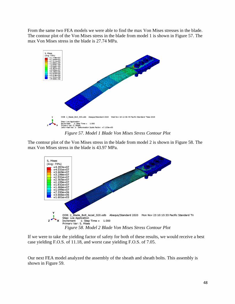
48
From the same two FEA models we were able to find the max Von Mises stresses in the blade.
The contour plot of the Von Mises stress in the blade from model 1 is shown in Figure 57. The
max Von Mises stress in the blade is 27.74 MPa.
Figure 57. Model 1 Blade Von Mises Stress Contour Plot
The contour plot of the Von Mises stress in the blade from model 2 is shown in Figure 58. The
max Von Mises stress in the blade is 43.97 MPa.
Figure 58. Model 2 Blade Von Mises Stress Contour Plot
If we were to take the yielding factor of safety for both of these results, we would receive a best
case yielding F.O.S. of 11.18, and worst case yielding F.O.S. of 7.05.
Our next FEA model analyzed the assembly of the sheath and sheath bolts. This assembly is
shown in Figure 59.

49
Figure 59. Sheath and Sheath Bolt Assembly
The material properties used in FEA modeling for the bolts and sheath are shown in Table 10.
Table 10. Material Properties for Bolts and Sheath
Steel Bolts 6061 Aluminum Sheath
Yield Strength (MPa) 420 Yield Strength (MPa) 310
Young’s Modulus (GPa) 200 Young’s Modulus (GPa) 69
Poisson's Ratio 0.3 Poisson's Ratio 0.35
We were able to calculate a conservative estimate of the centrifugal force by assuming that the
sheath was a point mass rotating around the center of the disk. Therefore, we used the following
formula:
𝐹𝑐𝑒𝑛𝑡𝑟𝑖𝑓𝑢𝑔𝑎𝑙 = 𝑚𝜔2𝑟
In this equation, m is the 0.37266kg mass of the sheath, 𝜔 is the 100 rad/sec angular velocity,
and r is the 1.15 m distance from center of rotation on the disk to the point mass located at the
end of the sheath. From this formula we calculated the centrifugal force of the sheath to be
4,285.59 N. Using this centrifugal force, we calculated a body force that we could apply to the
entire volume of the sheath using the following formula:
𝐵𝑜𝑑𝑦 𝐹𝑜𝑟𝑐𝑒 =𝐹𝑐𝑒𝑛𝑡𝑟𝑖𝑓𝑢𝑔𝑎𝑙
𝑉𝑠ℎ𝑒𝑎𝑡ℎ
Using this formula and knowing that the volume of the sheath was 0.00013897 𝑚3, we were able
to calculate that the body force on the sheath was 30,838,238.47 N/𝑚3. Next, we applied this
body force and the 0.7 N drag force to our Abaqus FEA model as shown in Figure 60.
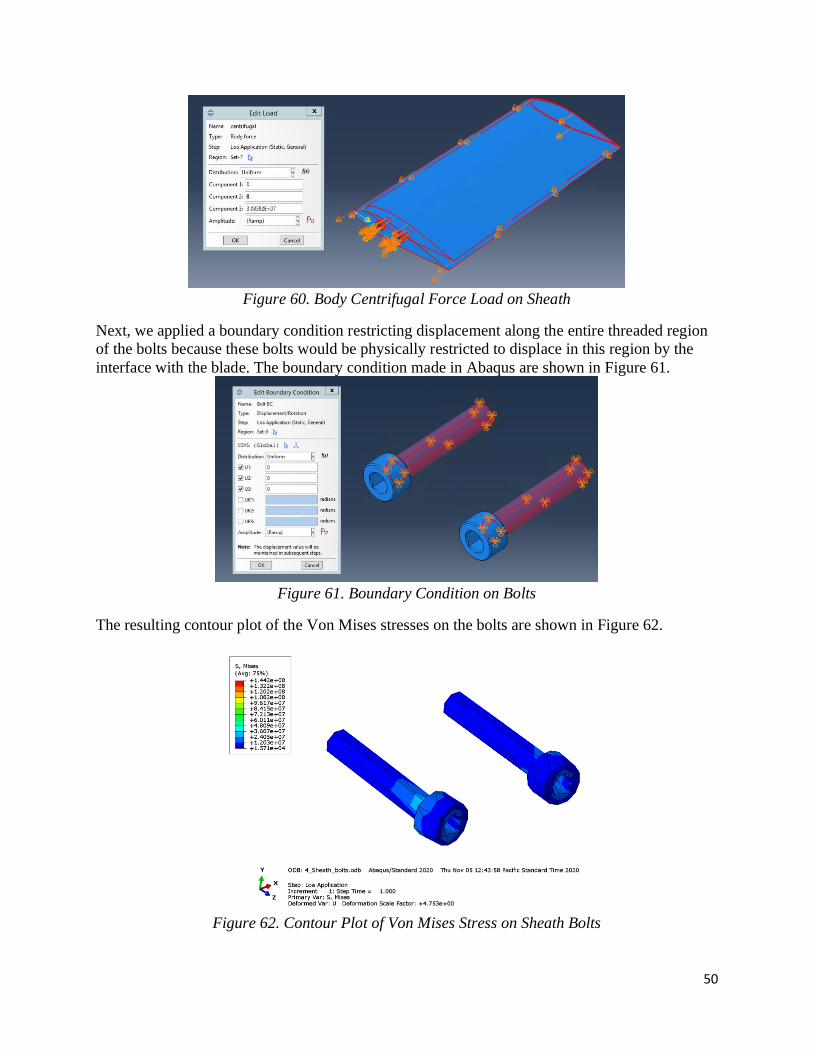
50
Figure 60. Body Centrifugal Force Load on Sheath
Next, we applied a boundary condition restricting displacement along the entire threaded region
of the bolts because these bolts would be physically restricted to displace in this region by the
interface with the blade. The boundary condition made in Abaqus are shown in Figure 61.
Figure 61. Boundary Condition on Bolts
The resulting contour plot of the Von Mises stresses on the bolts are shown in Figure 62.
Figure 62. Contour Plot of Von Mises Stress on Sheath Bolts

51
The resulting contour plot of the Von Mises stresses on the sheath are shown in Figure 63.
Figure 63. Contour Plot of Von Mises Stress on Sheath
Noting that the max Von Mises stress was 144.2 MPa on the bolts and 111.2 MPa on the sheath,
we were able to calculate the yielding factor of safety using the following equation:
𝐹. 𝑂. 𝑆. = 𝜎𝑢𝑙𝑡/𝜎𝑎𝑐𝑡𝑢𝑎𝑙
The resulting max Von Mises stresses and F.O.S. of the bolts and sheath are shown in Table 11.
Table 11. Max Von Mises Stress and F.O.S. for Sheath and Bolts
Component Max Von Mises Bolt Stress (MPa) F.O.S
Bolts 144.2 2.91
Sheath 111.2 2.79
The last assembly we modeled in Abaqus was the disk and bolt assembly in order to find the Von
Mises stress that occur in the disk as a result of the blade rotating at 100 rad/s. The assembly is
shown in Figure 64.
Figure 64. Disk and Bolt Assembly

52
In this model we applied the centrifugal force of the blade that we previously calculated and
applied that force as a body force on the bolts. Knowing that the volume of the bolts was
0.00041931 m^3, and the centrifugal force was 50,901.63 N, we calculated that the centrifugal
body force on the bolts was 121,393,789.8 N/m^3. The body force loading on the bolts is shown
in Figure 65.
For the boundary conditions, we restricted the displacement of all surfaces on the disk that were
in contact with the bolts in the x, y, and z directions. The boundary conditions are shown in
Figure 66.
Figure 66. Boundary Conditions on Disk
The resulting disk Von Mises stress contour plot is shown in Figure 67.
Figure 65. Centrifugal Body Force Loading on Bolts

53
Figure 67. Disk Von Mises Stress Contour Plot
Using the max Von Mises stress from the contour plot and the yielding F.O.S. equation
previously mentioned, we were able to calculate the yielding F.O.S. of the disk. The max Von
Mises stress and yielding factor of safety for the disk are listed in Table 12.
Table 12. Disk Max Von Mises Stress and Yielding F.O.S.
Component Max Von Mises Bolt Stress (MPa) F.O.S
Disk 5.610 55.26
8. Project Management
This section will discuss the main project deliverables, when they were due, and how we
attempted to stay organized in order to adhere to our timeline. Throughout the duration of this
project, we were in a constant battle to keep our Gantt up to date with our changes and updates to
the Scope of Work. We did not commence building and testing of the finalized design during
Fall quarter. Due to the COVID-19 pandemic we were instead tasked with designing the rotating
blade system.
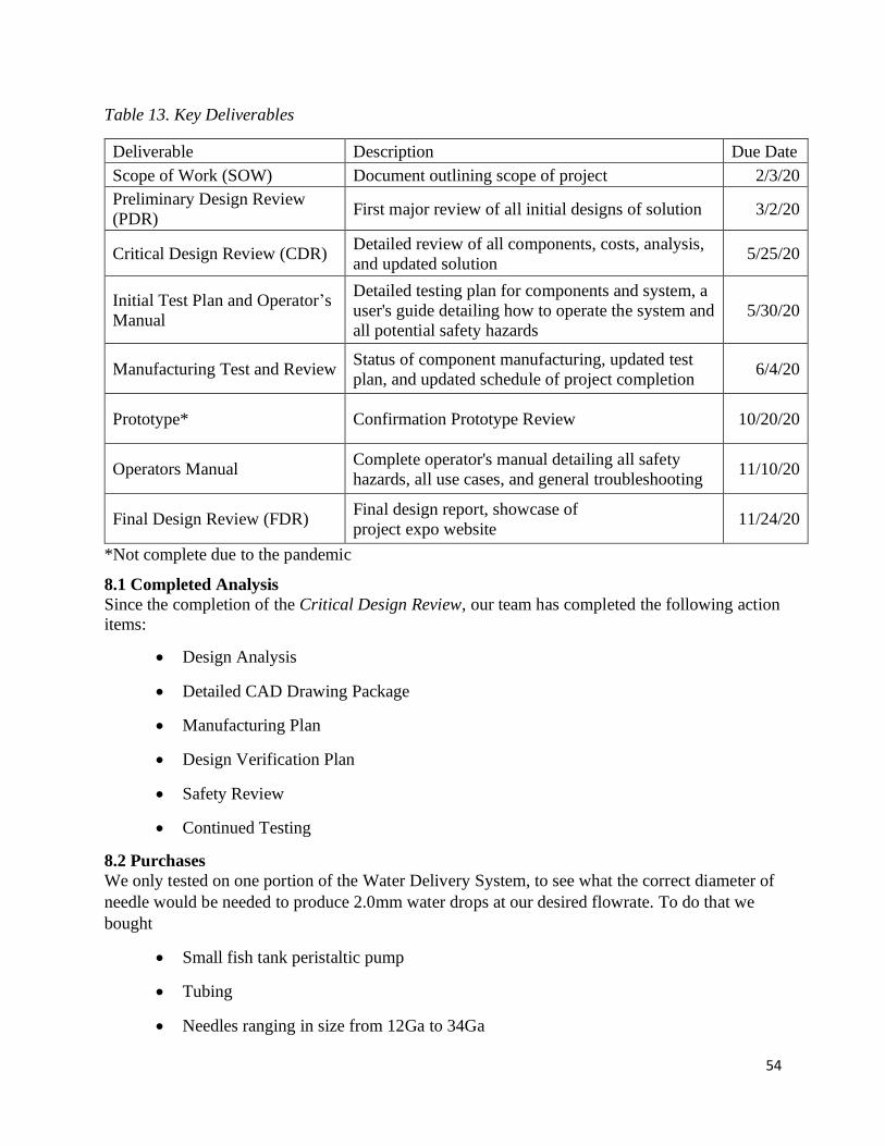
54
Table 13. Key Deliverables
Deliverable Description Due Date
Scope of Work (SOW) Document outlining scope of project 2/3/20
Preliminary Design Review
(PDR) First major review of all initial designs of solution 3/2/20
Critical Design Review (CDR) Detailed review of all components, costs, analysis,
and updated solution 5/25/20
Initial Test Plan and Operator’s
Manual
Detailed testing plan for components and system, a
user's guide detailing how to operate the system and
all potential safety hazards
5/30/20
Manufacturing Test and Review Status of component manufacturing, updated test
plan, and updated schedule of project completion 6/4/20
Prototype* Confirmation Prototype Review 10/20/20
Operators Manual Complete operator's manual detailing all safety
hazards, all use cases, and general troubleshooting 11/10/20
Final Design Review (FDR) Final design report, showcase of
project expo website 11/24/20
*Not complete due to the pandemic
8.1 Completed Analysis
Since the completion of the Critical Design Review, our team has completed the following action
items:
• Design Analysis
• Detailed CAD Drawing Package
• Manufacturing Plan
• Design Verification Plan
• Safety Review
• Continued Testing
8.2 Purchases
We only tested on one portion of the Water Delivery System, to see what the correct diameter of
needle would be needed to produce 2.0mm water drops at our desired flowrate. To do that we
bought
• Small fish tank peristaltic pump
• Tubing
• Needles ranging in size from 12Ga to 34Ga

55
A cost prediction for the entire system is included with the indented Bill of Materials (iBOM).
The iBOM is a document which lists all of the purchases that would need to be made for both the
Water Delivery System and the Rotating Blade System to be built and can be found in Appendix
L.
8.3 Effectiveness of Planning
We maintain that the method of planning that we used was successful. The use of the Gantt
chart, found in Appendix I, to monitor large scale progress worked very well to keep us on
schedule. The use of Weekly Status Reports was very helpful in reminding us what we needed to
achieve each week in order to keep up with the Gantt chart.
9. Conclusions and Recommendations
Unfortunately, due to the COVID-19 pandemic, our senior project was not able to complete the
manufacturing of much more than a single testing section. Instead of building the water delivery
system which was the scope of our project up to Fall quarter 2020, we spent the remainder of our
time designing the rotating blade system. Both systems are integrated and fulfill the majority of
requirements. The biggest requirement that we were not able to meet was the initial budget
estimate, mainly due to the additional system that requires custom machining processes. We are
confident that the water delivery system will be able to work well for an extended period of time,
given it is well maintained. One possible potential issue is the pressure rating of the peristaltic
pump. The pump is rated to 20psi operating pressure, and we estimate that our system will have
a maximum operating pressure of 15.8 psi. See Appendix U for the MatLab script we used to
calculate this pressure estimate. This leaves us with a smaller factor of safety than we would
have liked, however a pump that achieves that factor of safety would be more costly. One actual
shortcoming was that we did not meet the weight requirement for the fluid delivery system. This
portion of the project was overweight by a small margin. This missed specification was partially
due to balancing material and component costs and weight. It was also an ambitious and fairly
low-priority specification from the start of the project.
If we could do this project differently, we would have worked towards a more solidified scope
from the start of the project. We would have clarified this with TTP so that we did not have to
scramble to redesign and add new specifications to the project later on. This issue was partially
due to the pandemic. Our scope for this project went through two major changes. One was when
we realized the rotating blade system was going to be too dangerous to manufacture on campus,
and one when the pandemic threatened to close the machine shops on campus. Overall, we have
really enjoyed working with TTP. They have set aside a lot of time for us to talk with them and
review designs and ideas. We really appreciate all of their help and support.
Next Steps
We are confident that the rotating blade system will be a success, but due to complications with
the motor manufacturer, we were unable to get information until late in the quarter. If someone
were to spend additional time refining our designs, we would recommend focusing on the
connection between motor and disk. The disk and blade and connections were thoroughly
investigated, and we are confident that they will hold up under the loads we predicted them to be
under. All systems would need to be tested to ensure that the whole system follows our analysis.

56
Those tests would follow similar template to how we tested the single dropper branch. It is
incredibly vital that all precautions are taken with the rotating blade system as if failure were to
occur then there would be rapidly moving projectiles that would be dangerous to anyone in the
vicinity.
Another necessary next step is to find a place to set up and operate the system. We envisioned an
enclosed testing area with extra safety precautions in case of accidents.
57
References:
[1] Xu J Z 2011 A study on performance influences of airfoil aerodynamic parameters and
evaluation indicators for the roughness sensitivity on wind turbine blade
[2] Ashby M F, Shercliff H and Cebon D Materials: Engineering, Science, Processing and
Design
[3] Bartolome, Luis. Prospective challenges in the experimentation of the rain erosion on the
leading edge of wind turbine blades. Wind Energy
[4] Gohardani O 2011 Impact of erosion testing aspects on current and future flight conditions
[5] Pritchard, Philip. Fox and McDonald’s Introduction to Fluid Mechanics
[6] Field P R, Hand W, Cappelluti G and McMillan A 2012 Hail threat standardization
[7] de Vries, Eize. SGRE brings leading-edge protection as retrofit. Wind Power Monthly
[8] Sareen A, Chinmay S A and Selig M S 2013 Effects of leading edge erosion on wind
turbine blade performance Wind Energy
[9] Kumar B G, Singh B G and Nakamura T 2002 Degradation of carbon fiber-reinforced epoxy
composites by ultraviolet radiation and condensation Compos. Mater.
[10] Maniaci, David. Leading Edge Erosion. Sandia Laboratory
[11] DNVGL – RP0171. Testing of rotor blade erosion protection systems
[12] ASTM International 2011 Standard Test Method for Liquid Impingement Erosion Using
Rotating Apparatus
[13] Diarkis 2013 San and Rain Erosion Testing. Available:
http://diarkis.com/index.php/analytics/sandrain-erosion-testing
[14] Dear J P and Field J E 1988 High-speed photography of surface geometry effects in
liquid/solid impact
[15] Gurit 2013 Guid to composites. Available:
www.gurit.com/files/documents/Gurit_Guide_to_Composites.pdf.
[16] Keegan, M. H. On Erosion Issues Associated with the Leading Edge of Wind Turbine
Blades
[17] 3M 2011 Wind Energy. Available:
http://solutions.3m.com/wps/portal/3M/en_US/Wind/Energy
[18] Dalili, N. A Review of Surface Engineering Issues Critical to Wind Turbine Performance.
Renewable and Sustainable Energy Reviews
[19] University of Dayton Research Institute 2013 Rain erosion test facility. Available:
www.udri.udayton.edu/NONSTRUCTURALMATERIALS/COATINGS/Pages/RainErosio
nTestFacility.aspx
[20] Elert G and Volynets I 2001 Diameter of a raindrop. Available:
http://hypertextbook.com/facts/2001/IgorVolynets.shtml
[21] Plenzer, Ryszard. Elastic and Strength Properties of OSB Layers
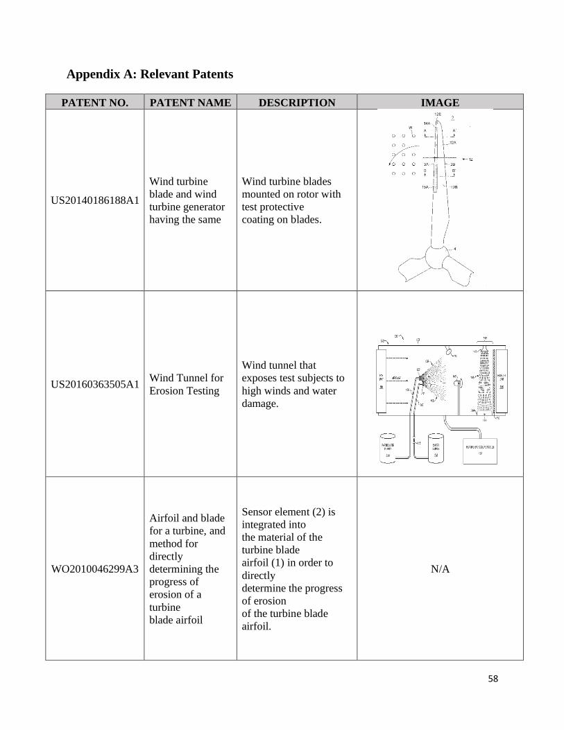
58
Appendix A: Relevant Patents
PATENT NO. PATENT NAME DESCRIPTION IMAGE
US20140186188A1
Wind turbine
blade and wind
turbine generator
having the same
Wind turbine blades
mounted on rotor with
test protective
coating on blades.
US20160363505A1 Wind Tunnel for
Erosion Testing
Wind tunnel that
exposes test subjects to
high winds and water
damage.
WO2010046299A3
Airfoil and blade
for a turbine, and
method for
directly
determining the
progress of
erosion of a
turbine
blade airfoil
Sensor element (2) is
integrated into
the material of the
turbine blade
airfoil (1) in order to
directly
determine the progress
of erosion
of the turbine blade
airfoil.
N/A
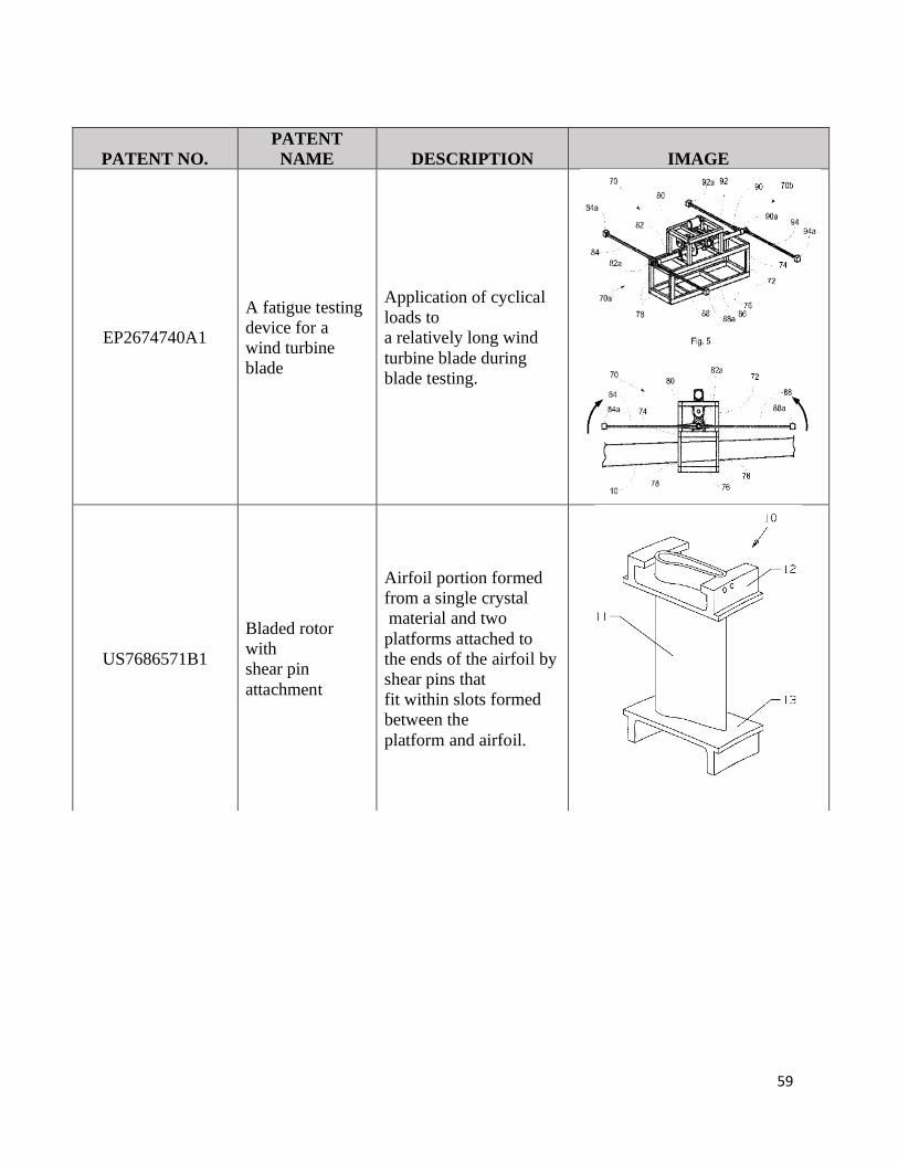
59
PATENT NO.
PATENT
NAME DESCRIPTION IMAGE
EP2674740A1
A fatigue testing
device for a
wind turbine
blade
Application of cyclical
loads to
a relatively long wind
turbine blade during
blade testing.
US7686571B1
Bladed rotor
with
shear pin
attachment
Airfoil portion formed
from a single crystal
material and two
platforms attached to
the ends of the airfoil by
shear pins that
fit within slots formed
between the
platform and airfoil.
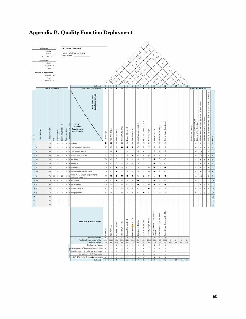
60
Appendix B: Quality Function Deployment
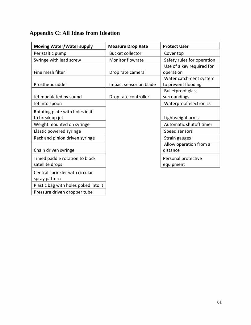
61
Appendix C: All Ideas from Ideation
Moving Water/Water supply Measure Drop Rate Protect User
Peristaltic pump Bucket collector Cover top
Syringe with lead screw Monitor flowrate Safety rules for operation
Fine mesh filter Drop rate camera Use of a key required for operation
Prosthetic udder Impact sensor on blade Water catchment system to prevent flooding
Jet modulated by sound Drop rate controller Bulletproof glass surroundings
Jet into spoon Waterproof electronics
Rotating plate with holes in it to break up jet Lightweight arms
Weight mounted on syringe Automatic shutoff timer
Elastic powered syringe Speed sensors
Rack and pinion driven syringe Strain gauges
Chain driven syringe Allow operation from a distance
Timed paddle rotation to block satellite drops
Personal protective equipment
Central sprinkler with circular spray pattern
Plastic bag with holes poked into it
Pressure driven dropper tube

62
Appendix D: Pugh Matrices
1. Support Water Delivery System

63
2. Create Water Droplets

64
Appendix E: Morphological Matrix
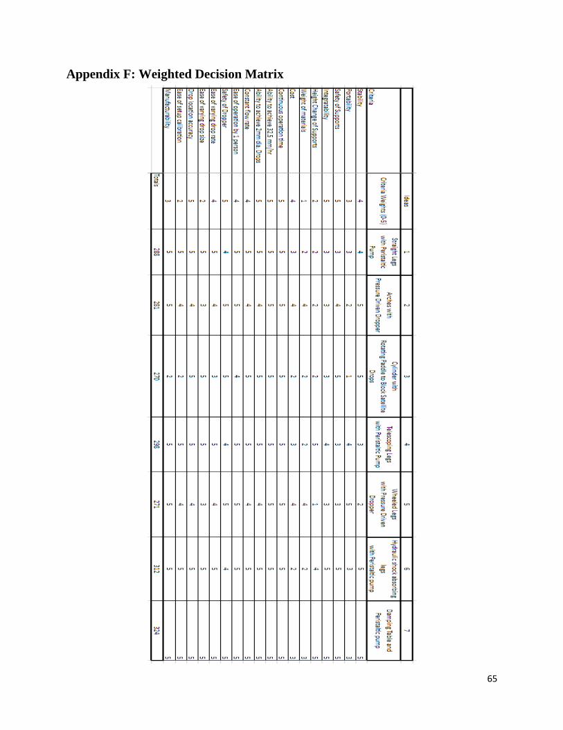
65
Appendix F: Weighted Decision Matrix

66
Appendix G: Design Hazard Checklist
Y N
Y 1. Will any part of the design create hazardous revolving, reciprocating, running,
shearing, punching, pressing, squeezing, drawing, cutting, rolling, mixing or
similar action, including pinch points and sheer points?
Y 2. Can any part of the design undergo high accelerations/decelerations?
Y 3. Will the system have any large moving masses or large forces?
Y 4. Would it be possible for the system produce a projectile?
Y 5. Would it be possible for the system to fall under gravity creating injury?
N 6. Will a user be exposed to overhanging weights as part of the design?
Y 7. Will the system have any sharp edges?
N 8. Will any part of the electrical systems not be grounded?
Y 9. Will there be any large batteries or electrical voltage in the system above 40 V?
N 10. Will there be any stored energy in the system such as batteries, flywheels,
hanging weights or pressurized fluids?
N 11. Will there be any explosive or flammable liquids, gases, or dust fuel as part of
the system?
N 12. Will the user of the design be required to exert any abnormal effort or physical
posture during the use of the design?
N 13. Will there be any materials known to be hazardous to humans involved in
either the design or the manufacturing of the design?
Y 14. Can the system generate high levels of noise?
N 15. Will the device/system be exposed to extreme environmental conditions such
as fog, humidity, cold, high temperatures, etc?
Y 16. Is it possible for the system to be used in an unsafe manner?
Y 17. Will there be any other potential hazards not listed above? If yes, please
explain on reverse.

67
Description of Hazard Planned Corrective Action
Crushed fingers in peristaltic
pump
Do not touch when in use
Decapitation, limb severing,
severe bruising or laceration
from rapidly moving blades
Stay far away when machine is in use.
Have operation station separate from
physical machine.
Flying attachments striking
user
Stay far away when machine is in use.
Have operation station separate from
physical machine.
Tip over Ensure machine is fully stable for use.
User mount samples of appropriate weight.
Electrocution Using heavy duty motor to spin heavy
blades and also using electricity to power
peristaltic pumps
Potential loud noise User wears ear protection
Catching tubing in rotating
blade
Zip tie or affix tubing so that it stays well
away from the moving blades
Flooding
Use large basin to catch any excess water
or overflow. Use over a drain so that room
does not flood

68
Appendix H: Preliminary Calculations Determining the size of the needle based off of Tate’s Method:
Free Body Diagram:
∑ 𝐹 = 0
2𝜋𝑟𝑛𝑒𝑒𝑑𝑙𝑒𝜎𝑤𝑎𝑡𝑒𝑟 − 𝑚𝑤𝑎𝑡𝑒𝑟𝑔 = 0
2𝜋𝑟𝑛𝑒𝑒𝑑𝑙𝑒𝜎𝑤𝑎𝑡𝑒𝑟 = (𝜌𝑤𝑎𝑡𝑒𝑟𝑉𝑑𝑟𝑜𝑝)𝑔
𝑟𝑛𝑒𝑒𝑑𝑙𝑒 =𝜌𝑤𝑎𝑡𝑒𝑟
43
𝜋𝑅𝑤𝑎𝑡𝑒𝑟3 𝑔
2𝜋𝜎𝑤𝑎𝑡𝑒𝑟
𝑟𝑛𝑒𝑒𝑑𝑙𝑒 =2𝜌𝑤𝑎𝑡𝑒𝑟𝑅𝑤𝑎𝑡𝑒𝑟
3 𝑔
3𝜎𝑤𝑎𝑡𝑒𝑟
𝑑𝑛𝑒𝑒𝑑𝑙𝑒 = 4 (1000
𝑘𝑔𝑚3) (9.81
𝑚𝑠2) (0.001𝑚)3
3(0.072𝑘𝑔𝑠2 )
𝑑𝑛𝑒𝑒𝑑𝑙𝑒 = 0.182𝑚

69
Finding velocity of water drop at blade surface:
For droplet sizes of 0.1mm to 3mm, the terminal velocity of the drop may be defined using the
empirical relation in ASTM G73-10:
𝑣𝑑𝑟𝑜𝑝,𝑚𝑎𝑥 = 4.0𝑑0.56 (𝑚
𝑠)
Using the above equation and other relations from ASTM G73-10 seen below,
𝑥(𝑡) = 𝑣𝑑𝑟𝑜𝑝,𝑚𝑎𝑥𝑡 +𝑣𝑑𝑟𝑜𝑝,𝑚𝑎𝑥
2
𝑔(𝑒
−𝑔𝑡
𝑣𝑑𝑟𝑜𝑝,𝑚𝑎𝑥 − 1)
𝑣(𝑡) = 𝑣𝑑𝑟𝑜𝑝,𝑚𝑎𝑥 (1 − 𝑒−
𝑔𝑡𝑣𝑑𝑟𝑜𝑝,𝑚𝑎𝑥)
We find that the velocity of the drop, regardless of its diameter, will be less than 2 m/s when it
makes contact with the blade. A numerical solution in Excel was used to find the table below.
d [mm] v_drop_max [m/s] v (x = 20cm)
[m/s]
0.5 2.713 1.532
1.0 4.000 1.696
1.5 5.020 1.754
2.0 5.897 1.773
2.5 6.682 1.809
3.0 7.400 1.835

70
Appendix I: Gantt Chart

71
Appendix J: Concept Model Build Day Images
Concept Model Image
Parastaltic pump to syringe tip
Jet broken up by sound
Rack and Pinion driven syringe

72
Timed Paddle rotation to block satellite drops
Plastic Bag with hole in it

Appendix K: DVP&R
Fluid Delivery System:

2
Rotating Blade System:

3
Appendix L: Indented Bill of Materials
Assy Level Part Number Description Matl Vendor Qty Cost Ttl Cost
Lvl0 Lvl1 Lvl2 Lvl3
0 100000 Final Assembly
1 101000 Leg Assembly ------ 6
2 101001 90° elbow for 1" Sch. 40 Galvanized Pipe McMaster 2 6.53$ 78.36$
2 101002 1" Schedule 40 60" long Galvanized Pipe McMaster 1 60.06$ 360.36$
2 101003 1" Schedule 40 12" Galvanized Pipe McMaster 1 17.37$ 104.22$
2 101004 1" Schedule 40 6" Galvanized Pipe McMaster 1 7.79$ 46.74$
2 101005 Through-hole reducer Aluminum McMaster 1 19.00$ 114.00$
2 101006 1" Floor Mounting Flange Aluminum McMaster 2 21.91$ 262.92$
2 101007 1/2"-13 bolt, 2 1/2" long (5pk) Zi nc-plated Steel McMaster 2 8.30$ 16.60$
2 101008 1/2"-13 Locknut (50pk) Zi nc-plated Steel McMaster 1 10.07$ 10.07$
2 101009 M12x1.75mm, 30mm long (10pk) Zi nc-plated Steel McMaster 2 7.32$ 14.64$
2 101010 M12 Washer (25pk) 316 Stai nless Steel McMaster 1 7.14$ 7.14$
2 101011 M12x1.75mm Locknut (10pk) 18-8 Stai nless Steel McMaster 2 6.76$ 13.52$
1 102000 Ring Assembly ------ 1
2 102001 Curved Struts (type 1 and 2) Zi nc-plated Steel McMaster 4 95.05$ 380.20$
2 102002 Strut Brackets (inner and outer) Zi nc-plated Steel McMaster 8 2.17$ 17.36$
2 102003 1/2"-13, 3" Long (5pk) 18-8 Stai nless Steel McMaster 4 5.42$ 21.68$
2 102004 Washer for 1/2" (50pk) 18-8 Stai nless Steel McMaster 1 6.25$ 6.25$
2 102005 1/2"-13 Locknut (10pk) 18-8 Stai nless Steel McMaster 2 4.79$ 9.58$
1 103000 Reservoi r Assembly ------ 1
2 103001 Plastic Pool Plastic ? 1 ?
2 103002 Seali ng caulk or epoxy Caulking Home Depot 1 2.58$ 2.58$
1 104000 Fluid Path Assembly ------ 1
2 104001 Peristaltic Pump Many McMaster 1 577.83$ 577.83$
2 104002 Cable Ties (100pk) Nylon McMaster 1 15.62$ 15.62$
2 104003 Flexible tubing (per foot) Rubber McMaster 200 0.97$ 194.00$
2 104004 Y-Connectors (10pk) Nylon McMaster 1 16.26$ 16.26$
2 104005 Threads-to-barb adapter for 1:12 flow splitter (10pk) Nylon McMaster 6 4.81$ 28.86$
2 104006 Reducer, for 3/8"x1/4" Tube ID (10pk) Nylon McMaster 1 5.29$ 5.29$
2 104007 In-line tubing filter Nylon McMaster 1 30.49$ 30.49$
2 104008 Al. stock for 1:12 flow di vi der Aluminum McMaster 1 37.73$ 37.73$
1 105000 Dropper Assembly 1
2 105001 Dropper PVC Pipe PVC ACE 48 2.99$ 143.52$
2 105002 1/4" Tube ID x 1/2 NPT Adapter (10pk) Nylon McMaster 5 5.35$ 26.75$
2 105003 1/2" pi pe cap PVC McMaster 48 0.28$ 13.44$
2 105004 10-32 MUNF to Luer adapter Nylon ISM 960 0.16$ 153.60$
2 105005 0.09mm ID nozzle (50pk) Many Amazon 20 14.89$ 297.80$
2 105006 Strut Mount Clamp Zi nc-plated Steel McMaster 48 1.31$ 62.88$
2 105007 M6x1mm 30mm Long (50pk) Zi nc-plated Steel McMaster 1 7.84$ 7.84$
2 105008 M6 Spacer, 17mm long Aluminum McMaster 48 1.52$ 72.96$
2 105009 M6 Strut Channel Nut (5pk) Zi nc-plated Steel McMaster 10 6.48$ 64.80$
1 106000 Curtain Hanging Parts 1
2 106001 Shower Curtains Vinyl Plastic McMaster 4 23.02$ 92.08$
2 106002 3/4" PVC pi pe PVC McMaster 3 5.67$ 17.01$
2 106003 3/4" PVC fittings PVC McMaster 3 0.28$ 0.84$
2 106004 Curtain Hooks (100pk) Zi nc-plated Steel McMaster 1 9.73$ 9.73$
2 106005 Plastic Rivets (25pk) Nylon McMaster 2 2.95 5.90$
1 107000 Rotating Blade System ------ 1
2 107001 Rotor Disk AL-6061 Machine Shop 1 2,000.00$ 2,000.00$
2 107002 Ai rfoi l Blade AL-6061 Machine Shop 3 2,000.00$ 6,000.00$
2 107003 Ai rfoi l Sheath AL-6061 Machine Shop 3 1,000.00$ 3,000.00$
2 107004 M30 x 3.5 mm thread x 110 mm Long Hex Bolt Zinc Yellow-Chromate Plated St McMaster 12 17.09$ 205.08$
2 107005 M30 x 3.5 mm Thread Hex Nut Zi nc-Plated Steel McMaster 12 4.04$ 48.48$
2 107006 M6 x 0.75 mm Thread, 30 mm Long Bolt Black-Oxi de Alloy Steel McMaster 6 3.91$ 23.46$
2 107007 Split-Tapered Bushing Steel McMaster 1 24.37$ 24.37$
2 107008 1/2"-20 Thread Size, 2-1/4" Long Hex Bolt Zinc Yellow-Chromate Plated St McMaster 6 14.69$ 88.14$
2 107009 1/2"-20 Thread Si ze Hex Nut Zinc Yellow-Chromate Plated St McMaster 6 0.17$ 1.02$
2 107010 PEWWE5-9-254T 900 RPM Motor Many Worldwide Electric 1 1,648.00$ 1,648.00$
Purchased Parts Total: 16,380.00$
Indented Bill of Material (BOM)
Wind Turbine Tester Assembly

4
Appendix M: Design Verification Plan
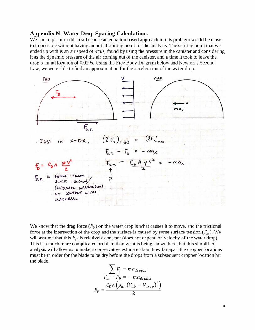
5
Appendix N: Water Drop Spacing Calculations We had to perform this test because an equation based approach to this problem would be close
to impossible without having an initial starting point for the analysis. The starting point that we
ended up with is an air speed of 9m/s, found by using the pressure in the canister and considering
it as the dynamic pressure of the air coming out of the canister, and a time it took to leave the
drop’s initial location of 0.029s. Using the Free Body Diagram below and Newton’s Second
Law, we were able to find an approximation for the acceleration of the water drop.
We know that the drag force (𝐹𝐷) on the water drop is what causes it to move, and the frictional
force at the intersection of the drop and the surface is caused by some surface tension (𝐹𝑠𝑡). We
will assume that this 𝐹𝑠𝑡 is relatively constant (does not depend on velocity of the water drop).
This is a much more complicated problem than what is being shown here, but this simplified
analysis will allow us to make a conservative estimate about how far apart the dropper locations
must be in order for the blade to be dry before the drops from a subsequent dropper location hit
the blade.
∑ 𝐹𝑥 = 𝑚𝑎𝑑𝑟𝑜𝑝,𝑥
𝐹𝑠𝑡 − 𝐹𝐷 = −𝑚𝑎𝑑𝑟𝑜𝑝,𝑥
𝐹𝐷 =𝐶𝐷𝐴 (𝜌𝑎𝑖𝑟(𝑉𝑎𝑖𝑟 − 𝑉𝑑𝑟𝑜𝑝)
2)
2

6
𝑎𝑑𝑟𝑜𝑝,𝑥 =𝐶𝐷𝐴 (𝜌𝑎𝑖𝑟(𝑉𝑎𝑖𝑟 − 𝑉𝑑𝑟𝑜𝑝)
2)
2𝑚−
𝐹𝑠𝑡
𝑚
∫ 𝑎𝑑𝑟𝑜𝑝,𝑥 𝑑𝑡 = ∫𝐶𝐷𝐴 (𝜌𝑎𝑖𝑟(𝑉𝑎𝑖𝑟 − 𝑉𝑑𝑟𝑜𝑝)
2)
2𝑚−
𝐹𝑠𝑡
𝑚𝑑𝑡
𝑉𝑑𝑟𝑜𝑝,𝑓 − 𝑉𝑑𝑟𝑜𝑝,𝑖 =𝐶𝐷𝐴𝜌𝑎𝑖𝑟
2𝑚∫(𝑉𝑎𝑖𝑟 − 𝑉𝑑𝑟𝑜𝑝)
2𝑑𝑡 −
𝐹𝑠𝑡
𝑚Δ𝑡
From this equation it is impossible to draw any conclusions because it is a nonlinear differential
equation. We shall therefore make the simplifying assumption that the difference between the
velocity of the air (𝑉𝑎𝑖𝑟) and the velocity of the drop (𝑉𝑑𝑟𝑜𝑝) will remain approximately constant.
We shall assume that
𝑉𝑎𝑖𝑟 − 𝑉𝑑𝑟𝑜𝑝 ≅ 0.9𝑉𝑎𝑖𝑟
From this assumption, we can resolve the equation to be
𝑉𝑑𝑟𝑜𝑝,𝑓 = (𝐶𝐷𝐴𝜌𝑎𝑖𝑟
2𝑚(0.9𝑉𝑎𝑖𝑟) −
𝐹𝑠𝑡
𝑚) Δ𝑡
Even having made all of these simplifying assumptions, we still have many unknowns. For
example, the shape of the water drop changes when it is hit with air, and in unpredictable ways.
This means that both the 𝐶𝐷 and the 𝐴 will be changing. The water drop also leaves a trail of
water as it moves along the blade, meaning that its mass is continuously changing. This is also
forgetting that there is also an impact that we have completely neglected. Based off of all of
these unmodelable parameters, we cannot predict the spacing of the droppers with any certainty.
We have therefore decided that we shall base our spacing off of what we have seen in photos
from machines already in use in the industry, and to charge whosoever uses this machine to
verify that our assumptions were correct, and change the spacing if not.
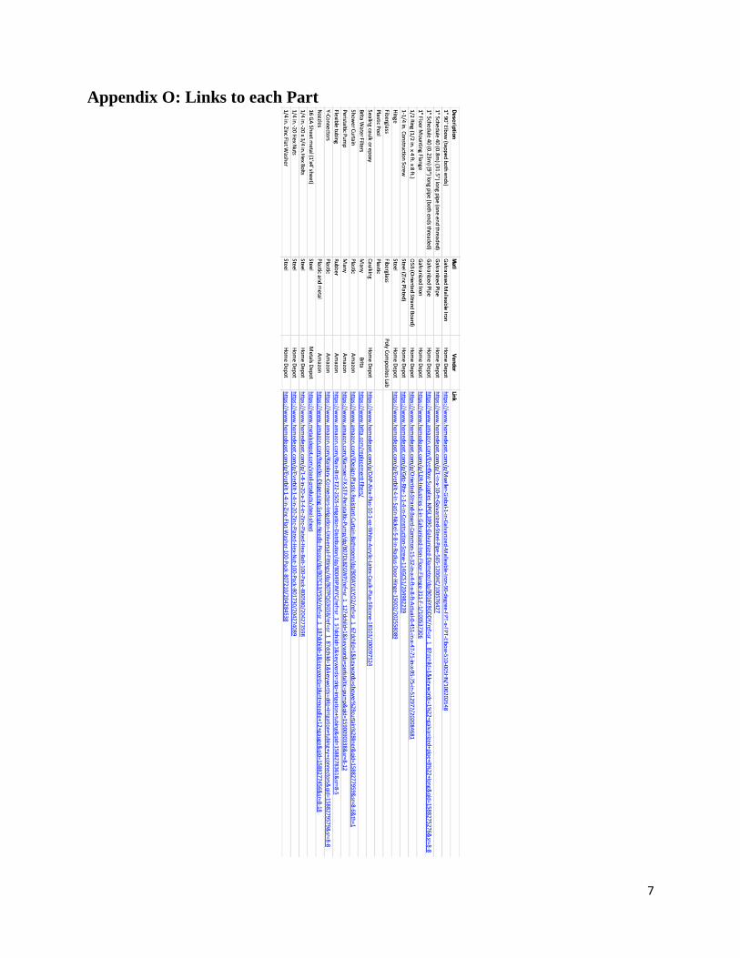
7
Appendix O: Links to each Part
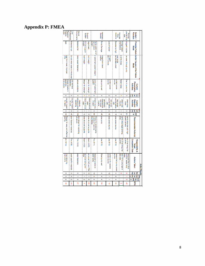
8
Appendix P: FMEA

9
Appendix Q: Centrifugal Force Excel Calculation
*The excel sheet has 2404 rows, so please reference attached excel file for
equations and more detail*
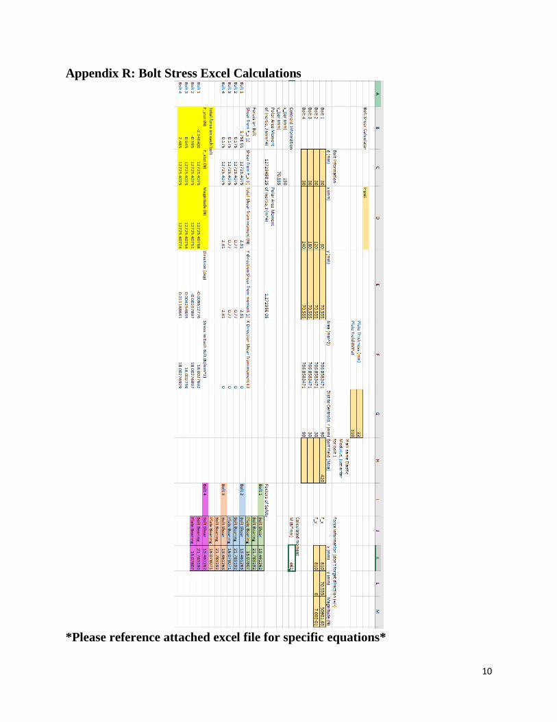
10
Appendix R: Bolt Stress Excel Calculations
*Please reference attached excel file for specific equations*

11
Appendix S: EES file for one dropper configuration
File is included in submission folder, but text is as follows:
"Model for 1 set of droppers"
"This system of equations is a rough model for one dropper configuration in our
Fluid Delivery System Design"
"The purpose of this script is to prove that the flowrate difference between 20
droppers in a row drawing from one pipe is negligible"
"Flow rates from each dropper nozzle are boxed in solutions output. Since they are
all very similar, the difference in dropper flowrate is negligible."
"Constants"
"density('Water', T=T_0, P=p_atm)"
rho=1.93 [slug/ft^3] "density of water"
T_0=70 [F]
p_atm = 2116.8 [lbf/ft^2] "atmospheric pressure"
g=32.2 [ft/s^2]
d=(1/48) [ft] "diameter of tubing"
d_nozzle = 0.000295 [ft] "ID of nozzles"
q_0 = 4.0163*10^(-4) "flow rate for 1 dropper configuration (ft^3/s)"
K_elbow = 0.3
K_nozzleexit = 1.0 "loss coeff for nozzle exit"
"kinematicviscosity(Water, T=T_0, P=p_atm)"
v_kin = 1.0503*10^(-5)
l_0_0_1 = 2 + 4.64 [ft]
l_nozzle = 1/24 "length of nozzle (ft)"
l_btwndroppers = 0.0328 [ft] "distance between droppers"
l_pump_0 = 5 [ft]
"Mass Balance"
q_1_2 = q_0 - q_1 "flow rate from spot 1 to 2 is the provided flowrate minus the
rate out of nozzle 1, ft^3/s"
q_2_3 = q_1_2 - q_2 "ft^3/s"
q_3_4 = q_2_3 - q_3 "ft^3/s"
q_4_5 = q_3_4 - q_4 "ft^3/s"
q_5_6 = q_4_5 - q_5 "ft^3/s"
q_6_7 = q_5_6 - q_6 "ft^3/s"
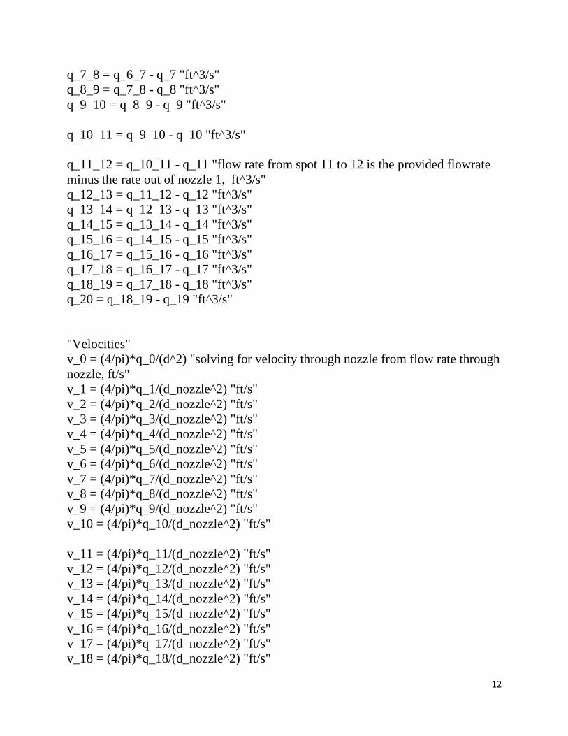
12
q_7_8 = q_6_7 - q_7 "ft^3/s"
q_8_9 = q_7_8 - q_8 "ft^3/s"
q_9_10 = q_8_9 - q_9 "ft^3/s"
q_10_11 = q_9_10 - q_10 "ft^3/s"
q_11_12 = q_10_11 - q_11 "flow rate from spot 11 to 12 is the provided flowrate
minus the rate out of nozzle 1, ft^3/s"
q_12_13 = q_11_12 - q_12 "ft^3/s"
q_13_14 = q_12_13 - q_13 "ft^3/s"
q_14_15 = q_13_14 - q_14 "ft^3/s"
q_15_16 = q_14_15 - q_15 "ft^3/s"
q_16_17 = q_15_16 - q_16 "ft^3/s"
q_17_18 = q_16_17 - q_17 "ft^3/s"
q_18_19 = q_17_18 - q_18 "ft^3/s"
q_20 = q_18_19 - q_19 "ft^3/s"
"Velocities"
v_0 = (4/pi)*q_0/(d^2) "solving for velocity through nozzle from flow rate through
nozzle, ft/s"
v_1 = (4/pi)*q_1/(d_nozzle^2) "ft/s"
v_2 = (4/pi)*q_2/(d_nozzle^2) "ft/s"
v_3 = (4/pi)*q_3/(d_nozzle^2) "ft/s"
v_4 = (4/pi)*q_4/(d_nozzle^2) "ft/s"
v_5 = (4/pi)*q_5/(d_nozzle^2) "ft/s"
v_6 = (4/pi)*q_6/(d_nozzle^2) "ft/s"
v_7 = (4/pi)*q_7/(d_nozzle^2) "ft/s"
v_8 = (4/pi)*q_8/(d_nozzle^2) "ft/s"
v_9 = (4/pi)*q_9/(d_nozzle^2) "ft/s"
v_10 = (4/pi)*q_10/(d_nozzle^2) "ft/s"
v_11 = (4/pi)*q_11/(d_nozzle^2) "ft/s"
v_12 = (4/pi)*q_12/(d_nozzle^2) "ft/s"
v_13 = (4/pi)*q_13/(d_nozzle^2) "ft/s"
v_14 = (4/pi)*q_14/(d_nozzle^2) "ft/s"
v_15 = (4/pi)*q_15/(d_nozzle^2) "ft/s"
v_16 = (4/pi)*q_16/(d_nozzle^2) "ft/s"
v_17 = (4/pi)*q_17/(d_nozzle^2) "ft/s"
v_18 = (4/pi)*q_18/(d_nozzle^2) "ft/s"

13
v_19 = (4/pi)*q_19/(d_nozzle^2) "ft/s"
v_20 = (4/pi)*q_20/(d_nozzle^2) "ft/s"
v_1_2 = (4/pi)*q_1_2/(d^2) "Solving for velocity between nozzles from flow rate
between nozzles, ft/s"
v_2_3 = (4/pi)*q_2_3/(d^2) "ft/s"
v_3_4 = (4/pi)*q_3_4/(d^2) "ft/s"
v_4_5 = (4/pi)*q_4_5/(d^2) "ft/s"
v_5_6 = (4/pi)*q_5_6/(d^2) "ft/s"
v_6_7 = (4/pi)*q_6_7/(d^2) "ft/s"
v_7_8 = (4/pi)*q_7_8/(d^2) "ft/s"
v_8_9 = (4/pi)*q_8_9/(d^2) "ft/s"
v_9_10 = (4/pi)*q_9_10/(d^2) "ft/s"
v_10_11 = (4/pi)*q_10_11/(d^2) "ft/s"
v_11_12 = (4/pi)*q_11_12/(d^2) "ft/s"
v_12_13 = (4/pi)*q_12_13/(d^2) "ft/s"
v_13_14 = (4/pi)*q_13_14/(d^2) "ft/s"
v_14_15 = (4/pi)*q_14_15/(d^2) "ft/s"
v_15_16 = (4/pi)*q_15_16/(d^2) "ft/s"
v_16_17 = (4/pi)*q_16_17/(d^2) "ft/s"
v_17_18 = (4/pi)*q_17_18/(d^2) "ft/s"
v_18_19 = (4/pi)*q_18_19/(d^2) "ft/s"
"Flowrates"
"Reynolds Numbers"
"Note: for small Nozzle ID reynolds number may go >2300 and indicate turbulent
flow which this file does not account for"
re_0 = v_0*d/v_kin "solving for Reynolds number for flow through nozzle"
re_1 = v_1*d_nozzle/v_kin
re_2 = v_2*d_nozzle/v_kin
re_3 = v_3*d_nozzle/v_kin
re_4 = v_4*d_nozzle/v_kin
re_5 = v_5*d_nozzle/v_kin
re_6 = v_6*d_nozzle/v_kin
re_7 = v_7*d_nozzle/v_kin
re_8 = v_8*d_nozzle/v_kin
re_9 = v_9*d_nozzle/v_kin
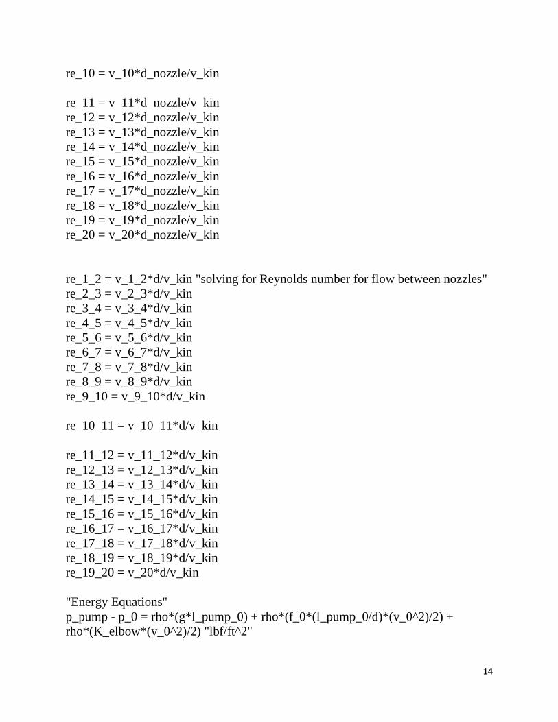
14
re_10 = v_10*d_nozzle/v_kin
re_11 = v_11*d_nozzle/v_kin
re_12 = v_12*d_nozzle/v_kin
re_13 = v_13*d_nozzle/v_kin
re_14 = v_14*d_nozzle/v_kin
re_15 = v_15*d_nozzle/v_kin
re_16 = v_16*d_nozzle/v_kin
re_17 = v_17*d_nozzle/v_kin
re_18 = v_18*d_nozzle/v_kin
re_19 = v_19*d_nozzle/v_kin
re_20 = v_20*d_nozzle/v_kin
re_1_2 = v_1_2*d/v_kin "solving for Reynolds number for flow between nozzles"
re_2_3 = v_2_3*d/v_kin
re_3_4 = v_3_4*d/v_kin
re_4_5 = v_4_5*d/v_kin
re_5_6 = v_5_6*d/v_kin
re_6_7 = v_6_7*d/v_kin
re_7_8 = v_7_8*d/v_kin
re_8_9 = v_8_9*d/v_kin
re_9_10 = v_9_10*d/v_kin
re_10_11 = v_10_11*d/v_kin
re_11_12 = v_11_12*d/v_kin
re_12_13 = v_12_13*d/v_kin
re_13_14 = v_13_14*d/v_kin
re_14_15 = v_14_15*d/v_kin
re_15_16 = v_15_16*d/v_kin
re_16_17 = v_16_17*d/v_kin
re_17_18 = v_17_18*d/v_kin
re_18_19 = v_18_19*d/v_kin
re_19_20 = v_20*d/v_kin
"Energy Equations"
p_pump - p_0 = rho*(g*l_pump_0) + rho*(f_0*(l_pump_0/d)*(v_0^2)/2) +
rho*(K_elbow*(v_0^2)/2) "lbf/ft^2"
15
p_0 - p_0_1 = rho*(f_0*(l_0_0_1/d)*(v_0^2)/2)+ 2*rho*(K_elbow*(v_0^2)/2)
"lbf/ft^2"
p_0_1 - p_atm = rho*((((v_1^2)-
(v_0^2))/(2))+(f_1*l_nozzle*v_1^2)/(d_nozzle*2)) +
rho*(K_nozzleexit*(v_1^2)/2) "lbf/ft^2"
p_1_2 - p_atm = rho*((((v_2^2)-
(v_1_2^2))/(2))+(f_2*l_nozzle*v_2^2)/(d_nozzle*2)) +
rho*(K_nozzleexit*(v_2^2)/2) "lbf/ft^2"
p_2_3 - p_atm = rho*((((v_3^2)-
(v_2_3^2))/(2))+(f_3*l_nozzle*v_3^2)/(d_nozzle*2)) +
rho*(K_nozzleexit*(v_3^2)/2) "lbf/ft^2"
p_3_4 - p_atm = rho*((((v_4^2)-
(v_3_4^2))/(2))+(f_4*l_nozzle*v_4^2)/(d_nozzle*2)) +
rho*(K_nozzleexit*(v_4^2)/2) "lbf/ft^2"
p_4_5 - p_atm = rho*((((v_5^2)-
(v_4_5^2))/(2))+(f_5*l_nozzle*v_5^2)/(d_nozzle*2)) +
rho*(K_nozzleexit*(v_5^2)/2) "lbf/ft^2"
p_5_6 - p_atm = rho*((((v_6^2)-
(v_5_6^2))/(2))+(f_6*l_nozzle*v_6^2)/(d_nozzle*2)) +
rho*(K_nozzleexit*(v_6^2)/2) "lbf/ft^2"
p_6_7 - p_atm = rho*((((v_7^2)-
(v_6_7^2))/(2))+(f_7*l_nozzle*v_7^2)/(d_nozzle*2)) +
rho*(K_nozzleexit*(v_7^2)/2) "lbf/ft^2"
p_7_8 - p_atm = rho*((((v_8^2)-
(v_7_8^2))/(2))+(f_8*l_nozzle*v_8^2)/(d_nozzle*2)) +
rho*(K_nozzleexit*(v_8^2)/2) "lbf/ft^2"
p_8_9 - p_atm = rho*((((v_9^2)-
(v_8_9^2))/(2))+(f_9*l_nozzle*v_9^2)/(d_nozzle*2)) +
rho*(K_nozzleexit*(v_9^2)/2) "lbf/ft^2"
p_9_10 - p_atm = rho*((((v_10^2)-
(v_9_10^2))/(2))+(f_10*l_nozzle*v_10^2)/(d_nozzle*2)) +
rho*(K_nozzleexit*(v_10^2)/2) "lbf/ft^2"
p_10_11 - p_atm = rho*((((v_11^2)-
(v_10_11^2))/(2))+(f_11*l_nozzle*v_11^2)/(d_nozzle*2)) +
rho*(K_nozzleexit*(v_11^2)/2) "lbf/ft^2"
16
p_11_12 - p_atm = rho*((((v_12^2)-
(v_11_12^2))/(2))+(f_12*l_nozzle*v_12^2)/(d_nozzle*2)) +
rho*(K_nozzleexit*(v_12^2)/2) "lbf/ft^2"
p_12_13 - p_atm = rho*((((v_13^2)-
(v_12_13^2))/(2))+(f_13*l_nozzle*v_13^2)/(d_nozzle*2)) +
rho*(K_nozzleexit*(v_13^2)/2) "lbf/ft^2"
p_13_14 - p_atm = rho*((((v_14^2)-
(v_13_14^2))/(2))+(f_14*l_nozzle*v_14^2)/(d_nozzle*2)) +
rho*(K_nozzleexit*(v_14^2)/2) "lbf/ft^2"
p_14_15 - p_atm = rho*((((v_15^2)-
(v_14_15^2))/(2))+(f_15*l_nozzle*v_15^2)/(d_nozzle*2)) +
rho*(K_nozzleexit*(v_15^2)/2) "lbf/ft^2"
p_15_16 - p_atm = rho*((((v_16^2)-
(v_15_16^2))/(2))+(f_16*l_nozzle*v_16^2)/(d_nozzle*2)) +
rho*(K_nozzleexit*(v_16^2)/2) "lbf/ft^2"
p_16_17 - p_atm = rho*((((v_17^2)-
(v_16_17^2))/(2))+(f_17*l_nozzle*v_17^2)/(d_nozzle*2)) +
rho*(K_nozzleexit*(v_17^2)/2) "lbf/ft^2"
p_17_18 - p_atm = rho*((((v_18^2)-
(v_17_18^2))/(2))+(f_18*l_nozzle*v_18^2)/(d_nozzle*2)) +
rho*(K_nozzleexit*(v_18^2)/2) "lbf/ft^2"
p_18_19 - p_atm = rho*((((v_19^2)-
(v_18_19^2))/(2))+(f_19*l_nozzle*v_19^2)/(d_nozzle*2)) +
rho*(K_nozzleexit*(v_19^2)/2) "lbf/ft^2"
p_19_20 - p_atm = rho*(f_20*l_nozzle*v_20^2)/(d_nozzle*2) +
rho*(K_nozzleexit*(v_20^2)/2) "lbf/ft^2"
p_0_1 - p_1_2 = rho*((((v_1_2^2)-
(v_0^2))/(2))+(f_1_2*l_btwndroppers*v_1_2^2)/(d*2)) "lbf/ft^2"
p_1_2 - p_2_3 = rho*((((v_2_3^2)-
(v_1_2^2))/(2))+(f_2_3*l_btwndroppers*v_2_3^2)/(d*2)) "lbf/ft^2"
p_2_3 - p_3_4 = rho*((((v_3_4^2)-
(v_2_3^2))/(2))+(f_3_4*l_btwndroppers*v_3_4^2)/(d*2)) "lbf/ft^2"
p_3_4 - p_4_5 = rho*((((v_4_5^2)-
(v_3_4^2))/(2))+(f_4_5*l_btwndroppers*v_4_5^2)/(d*2)) "lbf/ft^2"
p_4_5 - p_5_6 = rho*((((v_5_6^2)-
(v_4_5^2))/(2))+(f_5_6*l_btwndroppers*v_5_6^2)/(d*2)) "lbf/ft^2"
p_5_6 - p_6_7 = rho*((((v_6_7^2)-
(v_5_6^2))/(2))+(f_6_7*l_btwndroppers*v_6_7^2)/(d*2)) "lbf/ft^2"
17
p_6_7 - p_7_8 = rho*((((v_7_8^2)-
(v_6_7^2))/(2))+(f_7_8*l_btwndroppers*v_7_8^2)/(d*2)) "lbf/ft^2"
p_7_8 - p_8_9 = rho*((((v_8_9^2)-
(v_7_8^2))/(2))+(f_8_9*l_btwndroppers*v_8_9^2)/(d*2)) "lbf/ft^2"
p_8_9 - p_9_10 = rho*((((v_9_10^2)-
(v_8_9^2))/(2))+(f_9_10*l_btwndroppers*v_9_10^2)/(d*2)) "lbf/ft^2"
p_9_10 - p_10_11 = rho*((((v_10_11^2)-
(v_9_10^2))/(2))+(f_10_11*l_btwndroppers*v_10_11^2)/(d*2)) "lbf/ft^2"
p_10_11 - p_11_12 = rho*((((v_11_12^2)-
(v_10_11^2))/(2))+(f_11_12*l_btwndroppers*v_11_12^2)/(d*2)) "lbf/ft^2"
p_11_12 - p_12_13 = rho*((((v_12_13^2)-
(v_11_12^2))/(2))+(f_12_13*l_btwndroppers*v_12_13^2)/(d*2)) "lbf/ft^2"
p_12_13 - p_13_14 = rho*((((v_13_14^2)-
(v_12_13^2))/(2))+(f_13_14*l_btwndroppers*v_13_14^2)/(d*2)) "lbf/ft^2"
p_13_14 - p_14_15 = rho*((((v_14_15^2)-
(v_13_14^2))/(2))+(f_14_15*l_btwndroppers*v_14_15^2)/(d*2)) "lbf/ft^2"
p_14_15 - p_15_16 = rho*((((v_15_16^2)-
(v_14_15^2))/(2))+(f_15_16*l_btwndroppers*v_15_16^2)/(d*2)) "lbf/ft^2"
p_15_16 - p_16_17 = rho*((((v_16_17^2)-
(v_15_16^2))/(2))+(f_16_17*l_btwndroppers*v_16_17^2)/(d*2)) "lbf/ft^2"
p_16_17 - p_17_18 = rho*((((v_17_18^2)-
(v_16_17^2))/(2))+(f_17_18*l_btwndroppers*v_17_18^2)/(d*2)) "lbf/ft^2"
p_17_18 - p_18_19 = rho*((((v_18_19^2)-
(v_17_18^2))/(2))+(f_18_19*l_btwndroppers*v_18_19^2)/(d*2)) "lbf/ft^2"
p_18_19 - p_19_20 = rho*((((v_20^2)-
(v_18_19^2))/(2))+(f_19_20*l_btwndroppers*v_20^2)/(d*2)) "lbf/ft^2"
"Friction Factors"
f_0 = 64/re_0 "solves for friction factor for nozzles from reynolds number for
laminar flow"
f_1 = 64/re_1
f_2 = 64/re_2
f_3 = 64/re_3
f_4 = 64/re_4
f_5 = 64/re_5
f_6 = 64/re_6
f_7 = 64/re_7
f_8 = 64/re_8

18
f_9 = 64/re_9
f_10 = 64/re_10
f_11 = 64/re_11
f_12 = 64/re_12
f_13 = 64/re_13
f_14 = 64/re_14
f_15 = 64/re_15
f_16 = 64/re_16
f_17 = 64/re_17
f_18 = 64/re_18
f_19 = 64/re_19
f_20 = 64/re_20
f_1_2 = 64/re_1_2 "solves for friction factor between nozzles from reynolds
number for laminar flow"
f_2_3 = 64/re_2_3
f_3_4 = 64/re_3_4
f_4_5 = 64/re_4_5
f_5_6 = 64/re_5_6
f_6_7 = 64/re_6_7
f_7_8 = 64/re_7_8
f_8_9 = 64/re_8_9
f_9_10 = 64/re_9_10
f_10_11 = 64/re_10_11
f_11_12 = 64/re_11_12
f_12_13 = 64/re_12_13
f_13_14 = 64/re_13_14
f_14_15 = 64/re_14_15
f_15_16 = 64/re_15_16
f_16_17 = 64/re_16_17
f_17_18 = 64/re_17_18
f_18_19 = 64/re_18_19
f_19_20 = 64/re_19_20
p_pumprel = p_pump - p_atm
p_pumprelpsi = p_pumprel/144

19
Appendix T: Screenshot of Excel File ‘ME 430 Experiment Data’
Excel file is included in project submission folder

20
Appendix U: MatLab Script for fluid Pathway through FDS
The script is pasted in below. It is also included in the project submission folder.
File Name: ME430maxpressureshowerorientation.m
Script:
% Finding Max. Pressure in 'splitting tubes' fluid delivery system %% Estimating Reynold's Number for quarter inch tubing before 1st split (48 qtr
inch tubes worth of flow)
mu = 8.90*10^(-4); % Dynamic Viscosity of water (Pa*s)
Dtube = 0.00635; % ID of 1/4" tubing (0.25in = 0.00635m)
rhowater = 1000; % Density of water (kg/(m^3))
Ddrop = 0.002; % m , Drop Diameter = 2mm
numbrackets = 48; % number of brackets each tube goes to
numdroppersperbracket = 20; % number of droppers per dropper assembly
numdroppers = numbrackets*numdroppersperbracket; % total number of droppers
dropvolume = (4/3)*pi*(Ddrop/2)^3; % volume of each drop (m^3)
I = 9.05*10^(-6); % Drop Intensity Spec. from DNVGL-RP-0171
A = pi*((1.1^2)-(0.9^2)); % Exposure zone Area for rainfall (m^2)
P = I*A % Flow rate of water to reach spec. intensity (m^3/s)
dropfreq = P/(numdroppers*dropvolume); % Drop frequency (drops/sec)
tubearea = pi*(Dtube/2)^2; % tube cross section area (m^2)
Vavgatpumpoutlet = dropvolume*dropfreq*numdroppers/tubearea; % velocity of
fluid at pump outlet (m/s)
Reqtrtubingatpumpoutlet = rhowater*Vavgatpumpoutlet*Dtube/mu; % reynolds
number at pump outlet %% Finding required Flowrate from pump outlet
qatpumpoutlet = Vavgatpumpoutlet*tubearea; % flow rate at pump outlet (m^3/s)
qatpumpoutletmlpermin = qatpumpoutlet*(6*10^7); % flow rate at pump outlet
(ml/min) %% Estimating Reynold's Number for quarter inch tubing after 1st split into 2
tubes (24 dropper configurations worth of flow each)
numbrackets = 24; % number of brackets each tube supplies flow

21
numdroppers = numbrackets*numdroppersperbracket; % number of droppers each
tube supplies flow
Vavgafter1stsplit = dropvolume*dropfreq*numdroppers/tubearea; % Average
velocity in tube after 1st split (m/s) Reqtrtubingafter1stsplit = rhowater*Vavgafter1stsplit*Dtube/mu; % Reynold's
number after 1st split in tubing
%% Estimating Reynold's Number for quarter inch tubing after 2nd split (12
dropper configurations worth of flow each)
numbrackets = 12; % number of brackets each tube supplies flow
numdroppers = numbrackets*numdroppersperbracket; % number of droppers each
tube supplies flow
Vavgafter2ndsplit = dropvolume*dropfreq*numdroppers/tubearea; % Average
velocity in tube after 2nd split (m/s)
Reqtrtubingafter2ndsplit = rhowater*Vavgafter2ndsplit*Dtube/mu; % Reynold's
number after 2nd split in tubing
%% Finding Flowrate for experiment with 1x 1:12 splitter
qafter2ndsplit = Vavgafter2ndsplit*tubearea; % flow rate after 2nd tubing split
(m^3/s)
qafter2ndsplitmlpermin = qafter2ndsplit*(6*10^7); % flow rate after 2nd tubing
split (converts m^3/s to ml/min)
qafter12_1 = qafter2ndsplitmlpermin/12; % flow rate leaving 1:12 splitter (ml/min)
%% Estimating Reynold's Number for quarter inch tubing after 3rd split (1:12
splitter) (1 dropper configuration worth of flow each)
numbrackets = 1; % number of brackets each tube supplies flow
numdroppers = numbrackets*numdroppersperbracket; % number of droppers each
tube supplies flow
Vavgafter3rdsplit = dropvolume*dropfreq*numdroppers/tubearea; % Average
velocity in tube after 3rd split (m/s)
Reqtrtubingafter3rdsplit = rhowater*Vavgafter3rdsplit*Dtube/mu; % Reynold's
number after 3rd split in tubing
%% Estimating Reynold's Number for nozzle

22
Dnozzle = 0.00009; % 0.09mm = 0.00009m
dropvolume = (4/3)*pi*(Ddrop/2)^3; % volume of a drop (m^3)
nozzlearea = pi*(Dnozzle/2)^2; % Cross sectional area of nozzle (m^2)
Vavgnozzle = dropvolume*dropfreq/nozzlearea; % m/s
Renozzle = rhowater*Vavgnozzle*Dnozzle/mu; %% Total Expected Lengths of Tubing
Lqtrtubingatpumpoutlet = 1.5; % m, length of quarter inch tubing leaving pump
outlet
Rring = 1.1; % m
Cring = Rring*2*pi; % m
Lqtrtubingafter1stsplit = Rring + 1; % m, length of quarter inch tubing after 1st
split, from 1 tube to 2 tubes
Lqtrtubingafter2ndsplit = .5; % m, length of quarter inch tubing after 2nd split,
goes from 2 tubes to 4 tubes
Lqtrtubingafter3rdsplit = Rring + 0.5; % m, length of quarter inch tubing after 3rd
split, goes from 4 tubes to 48 tubes
Lnozzle = 0.0127; % m, length of needle producing drop (0.50in)
%% Total Head Loss from Lengths of Tubing and nozzle
fqtrtubingatpumpoutlet = 0.058; % Friction factor for quarter inch tubing with
turbulent flow from moody diagram (Req = 2600, e/D = 0.019)
fqtrtubingafter1stsplit = 64/Reqtrtubingafter1stsplit; % Friction factor for quarter
inch tubing with laminar flow
fqtrtubingafter2ndsplit = 64/Reqtrtubingafter2ndsplit; % Friction factor for quarter
inch tubing with laminar flow
fqtrtubingafter3rdsplit = 64/Reqtrtubingafter3rdsplit; % Friction factor for quarter
inch tubing with laminar flow
fnozzle = 64/Renozzle; % Friction factor for nozzle with laminar flow
hlmqtrtubingatpumpoutlet =
fqtrtubingatpumpoutlet*(Lqtrtubingatpumpoutlet/Dtube)*(Vavgatpumpoutlet^2)/2;
% (m^2)/(s^2), head loss for quarter inch tubing from outlet of pump to 1st split
hlmqtrtubingafter1stsplit =
fqtrtubingafter1stsplit*(Lqtrtubingafter1stsplit/Dtube)*(Vavgafter1stsplit^2)/2; %
(m^2)/(s^2), head loss for quarter inch tubing from 1st split to 2nd split

23
hlmqtrtubingafter2ndsplit =
fqtrtubingafter2ndsplit*(Lqtrtubingafter2ndsplit/Dtube)*(Vavgafter2ndsplit^2)/2;
% (m^2)/(s^2), head loss for quarter inch tubing from 2nd split to 1:12 splitter
hlmqtrtubingafter3rdsplit =
fqtrtubingafter3rdsplit*(Lqtrtubingafter3rdsplit/Dtube)*(Vavgafter3rdsplit^2)/2; %
(m^2)/(s^2), head loss for quarter inch tubing from 1:12 splitter to dropper config.
inlet hlmnozzle = fnozzle*(Lnozzle/Dnozzle)*(Vavgnozzle^2)/2; % (m^2)/(s^2), head
loss for nozzle
%% Head loss from transition from quarter inch tubing to nozzle tubing
AR = nozzlearea/tubearea; % equals about 0.0016 so go with 0 => contraction loss
coeff: Kc = 0.5
Kc = 0.5;
hlmcontraction = Kc*(Vavgdroppertubing^2)/2; %% Head loss from short lengths of PVC between tubing and nozzles
% negligible
%% Head loss from Y-connectors
Kteedividing = 0.9;
hlmteedividingqtr = 4*(Kteedividing*(Vavgatpumpoutlet^2)/2); % head loss for
2x Y-connectors, 1:12 flow divider, and in-line filter. conservative b/c using
average velocity at pump outlet for all 3
%% Total pressure loss from system
hlmtot = (2.5*9.81) + hlmqtrtubingatpumpoutlet + hlmteedividingqtr +
hlmqtrtubingafter1stsplit + hlmqtrtubingafter2ndsplit + hlmqtrtubingafter3rdsplit +
hlmcontraction + hlmnozzle; % (m^2)/(s^2), total head loss for fluid path
PtotPa = hlmtot*rhowater; % Pa
Ptotpsi = PtotPa*(1/6894.8) % pressure pump must overcome to push fluid through
tubings (psi)
Pnozzle = hlmnozzle*rhowater*(1/6894.8); % pressure loss through nozzle (psi)

24
Appendix V: Technical Drawing Package
Technical Drawing Package is included in project submission folder

A A
B B
2
2
1
1
Blade Coating Testing Design
DO NOT SCALE DRAWING
Full AssemblySHEET 1 OF 19
Joe B.
UNLESS OTHERWISE SPECIFIED:
SCALE: 1:20 WEIGHT:
REVDWG. NO.
ASIZE
TITLE:
NAME DATE
COMMENTS:
Q.A.
MFG APPR.
ENG APPR.
CHECKED
DRAWN
FINISH
MATERIAL
INTERPRET GEOMETRICTOLERANCING PER:
DIMENSIONS ARE IN CM UNLESS OTHERWISE SPECIFIEDTOLERANCES:FRACTIONALANGULAR: MACH BEND TWO PLACE DECIMAL THREE PLACE DECIMAL
APPLICATION
USED ONNEXT ASSY
PROPRIETARY AND CONFIDENTIAL
THE INFORMATION CONTAINED IN THISDRAWING IS THE SOLE PROPERTY OFTURBINE TECHNOLOGY PARTNERS. ANY REPRODUCTION IN PART OR AS A WHOLEWITHOUT THE WRITTEN PERMISSION OFTURBINE TECHNOLOGY PARTNERS IS PROHIBITED.
System # System Name1 Fluid Delivery System2 Rotating Blade System
1
2
SOLIDWORKS Educational Product. For Instructional Use Only.

A A
B B
2
2
1
1
Fluid Delivery System Assembly
DO NOT SCALE DRAWING
FDSSHEET 2 OF 19
JOE B.
UNLESS OTHERWISE SPECIFIED:
SCALE: 1:20 WEIGHT:
REVDWG. NO.
ASIZE
TITLE:
NAME DATE
COMMENTS:
Q.A.
MFG APPR.
ENG APPR.
CHECKED
DRAWN
FINISH
MATERIAL
INTERPRET GEOMETRICTOLERANCING PER:
DIMENSIONS ARE IN CMUNLESS OTHERWISE SPECIFIEDTOLERANCES:FRACTIONALANGULAR: MACH BEND TWO PLACE DECIMAL THREE PLACE DECIMAL
APPLICATION
USED ONNEXT ASSY
PROPRIETARY AND CONFIDENTIAL
THE INFORMATION CONTAINED IN THISDRAWING IS THE SOLE PROPERTY OFTURBINE TECHNOLOGY PARTNERS. ANY REPRODUCTION IN PART OR AS A WHOLEWITHOUT THE WRITTEN PERMISSION OFTURBINE TECHNOLOGY PARTNERS IS PROHIBITED.
Part # Subsystem/Part Quantity1 Reservoir 12 Leg Assembly 63 Ring Assembly 14 Dropper Assembly 485 Fluid Path Assembly 16 PVC Curtain Rail 37 Curtain Rail Fitting 38 Reservoir Spacer 6
1
2
4
3
5
6
7
8
SOLIDWORKS Educational Product. For Instructional Use Only.
A A
B B
2
2
1
1
Leg Assembly
DO NOT SCALE DRAWING
LEGSHEET 3 OF 19
JOE B.
UNLESS OTHERWISE SPECIFIED:
SCALE: 1:10 WEIGHT:
REVDWG. NO.
ASIZE
TITLE:
NAME DATE
COMMENTS:
Q.A.
MFG APPR.
ENG APPR.
CHECKED
DRAWN
FINISH
MATERIAL
INTERPRET GEOMETRICTOLERANCING PER:
DIMENSIONS ARE IN CMUNLESS OTHERWISE SPECIFIEDTOLERANCES:FRACTIONALANGULAR: MACH BEND TWO PLACE DECIMAL THREE PLACE DECIMAL
APPLICATION
USED ONNEXT ASSY
PROPRIETARY AND CONFIDENTIAL
THE INFORMATION CONTAINED IN THISDRAWING IS THE SOLE PROPERTY OFTURBINE TECHNOLOGY PARTNERS. ANY REPRODUCTION IN PART OR AS A WHOLEWITHOUT THE WRITTEN PERMISSION OFTURBINE TECHNOLOGY PARTNERS IS PROHIBITED.
11
9
106
3
4 2
1
57
8
Part # Part Name/Manuf. # Part Description Quantity (per leg) Material
1 1" Sch. 40 pipe, 52" long 1" Sch. 40 pipe, 52" long 1 Galvanized Steel2 4549K625 1" Sch. 40 pipe, 12" long 1 Galvanized Steel3 1" Sch. 40 pipe, 6" long 1" Sch. 40 pipe, 6" long 1 Galvanized Steel4 4638K135 90° fitting for 1" Sch. 40 2 Galvanized Steel5 4698T101 Through-hole reducer 1 Aluminum6 Leg Foot 2 bolt flange/foot 2 Aluminum7 90128A722 1/2"-13 bolt, 2 1/2" long 1 Zinc-plated Steel8 95615A210 1/2"-13 Locknut 1 Zinc-plated Steel
9 90128A297M12x1.75mm, 30mm
long 2 Zinc-plated Steel
10 98690A116 M12 Washer 4 316 Stainless Steel11 93625A400 M12x1.75mm Locknut 2 18-8 Stainless Steel
SOLIDWORKS Educational Product. For Instructional Use Only.

A A
B B
2
2
1
1
Ring Assembly
DO NOT SCALE DRAWING
RINGSHEET 4 OF 19
JOE B.
UNLESS OTHERWISE SPECIFIED:
SCALE: 1:15 WEIGHT:
REVDWG. NO.
ASIZE
TITLE:
NAME DATE
COMMENTS:
Q.A.
MFG APPR.
ENG APPR.
CHECKED
DRAWN
FINISH
MATERIAL
INTERPRET GEOMETRICTOLERANCING PER:
DIMENSIONS ARE IN CMUNLESS OTHERWISE SPECIFIEDTOLERANCES:FRACTIONALANGULAR: MACH BEND TWO PLACE DECIMAL THREE PLACE DECIMAL
APPLICATION
USED ONNEXT ASSY
PROPRIETARY AND CONFIDENTIAL
THE INFORMATION CONTAINED IN THISDRAWING IS THE SOLE PROPERTY OFTURBINE TECHNOLOGY PARTNERS. ANY REPRODUCTION IN PART OR AS A WHOLEWITHOUT THE WRITTEN PERMISSION OFTURBINE TECHNOLOGY PARTNERS IS PROHIBITED.
1
2
3
5
6
7
4
Part # Part Name/Manuf. # Part Description Quantity Material
1 Strut 1 90° curved strut, mounts to 2 legs 2 Zinc-plated Steel
2 Strut 2 90° curved strut, mounts to 1 leg 2 Zinc-plated Steel
3 Inner Strut Bracket Curved, 4 holes 4 Zinc-plated Steel4 Outer Strut Bracket Curved, 4 holes 4 Zinc-plated Steel5 92198A724 1/2"-13, 3" Long 16 18-8 Stainless Steel
6 92141A033 Washer for 1/2" bolt 32 18-8 Stainless Steel
7 91831A137 1/2"-13 Locknut 16 18-8 Stainless Steel
SOLIDWORKS Educational Product. For Instructional Use Only.
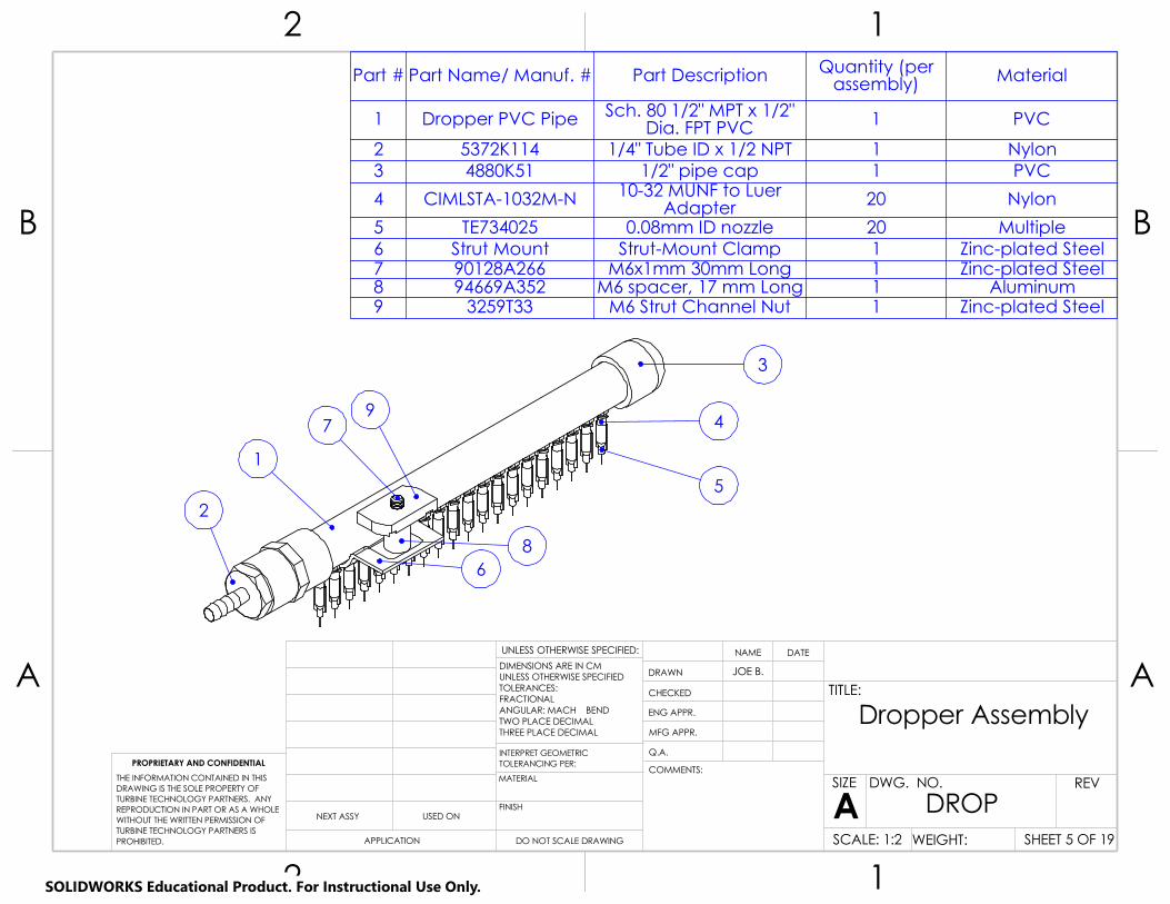
A A
B B
2
2
1
1
Dropper Assembly
DO NOT SCALE DRAWING
DROPSHEET 5 OF 19
JOE B.
UNLESS OTHERWISE SPECIFIED:
SCALE: 1:2 WEIGHT:
REVDWG. NO.
ASIZE
TITLE:
NAME DATE
COMMENTS:
Q.A.
MFG APPR.
ENG APPR.
CHECKED
DRAWN
FINISH
MATERIAL
INTERPRET GEOMETRICTOLERANCING PER:
DIMENSIONS ARE IN CMUNLESS OTHERWISE SPECIFIEDTOLERANCES:FRACTIONALANGULAR: MACH BEND TWO PLACE DECIMAL THREE PLACE DECIMAL
APPLICATION
USED ONNEXT ASSY
PROPRIETARY AND CONFIDENTIAL
THE INFORMATION CONTAINED IN THISDRAWING IS THE SOLE PROPERTY OFTURBINE TECHNOLOGY PARTNERS. ANY REPRODUCTION IN PART OR AS A WHOLEWITHOUT THE WRITTEN PERMISSION OFTURBINE TECHNOLOGY PARTNERS IS PROHIBITED.
Part # Part Name/ Manuf. # Part Description Quantity (per assembly) Material
1 Dropper PVC Pipe Sch. 80 1/2" MPT x 1/2" Dia. FPT PVC 1 PVC
2 5372K114 1/4" Tube ID x 1/2 NPT 1 Nylon3 4880K51 1/2" pipe cap 1 PVC
4 CIMLSTA-1032M-N 10-32 MUNF to Luer Adapter 20 Nylon
5 TE734025 0.08mm ID nozzle 20 Multiple6 Strut Mount Strut-Mount Clamp 1 Zinc-plated Steel7 90128A266 M6x1mm 30mm Long 1 Zinc-plated Steel8 94669A352 M6 spacer, 17 mm Long 1 Aluminum9 3259T33 M6 Strut Channel Nut 1 Zinc-plated Steel
2
1
3
9
8
7
6
4
5
SOLIDWORKS Educational Product. For Instructional Use Only.

A A
B B
2
2
1
1
Fluid Path Assembly
DO NOT SCALE DRAWING
PATHSHEET 6 OF 19
JOE B.
UNLESS OTHERWISE SPECIFIED:
SCALE: 1:15 WEIGHT:
REVDWG. NO.
ASIZE
TITLE:
NAME DATE
COMMENTS:
Q.A.
MFG APPR.
ENG APPR.
CHECKED
DRAWN
FINISH
MATERIAL
INTERPRET GEOMETRICTOLERANCING PER:
DIMENSIONS ARE IN CMUNLESS OTHERWISE SPECIFIEDTOLERANCES:FRACTIONALANGULAR: MACH BEND TWO PLACE DECIMAL THREE PLACE DECIMAL
APPLICATION
USED ONNEXT ASSY
PROPRIETARY AND CONFIDENTIAL
THE INFORMATION CONTAINED IN THISDRAWING IS THE SOLE PROPERTY OFTURBINE TECHNOLOGY PARTNERS. ANY REPRODUCTION IN PART OR AS A WHOLEWITHOUT THE WRITTEN PERMISSION OFTURBINE TECHNOLOGY PARTNERS IS PROHIBITED.
13
5
2
4
Part # Part Name/ Manuf. # Part Description Quantity Material1 43205K52 Peristaltic Pump 1 Multiple
2 5372K517 Reducer, for 3/8"x1/4" Tube ID 2 Nylon
3 4795K22 In-line Filter 1 Nylon4 5195T67 1/4" tubing lengths 57 Polyurethane5 5372K186 Y-connector 3 Nylon
6 1:12 Flow Divider Body Flow Divider Body 4 Aluminum
7 5372K112Adapter, for 1/4" Tube ID x 1/4 NPT
Male52 Nylon
6
7
SOLIDWORKS Educational Product. For Instructional Use Only.
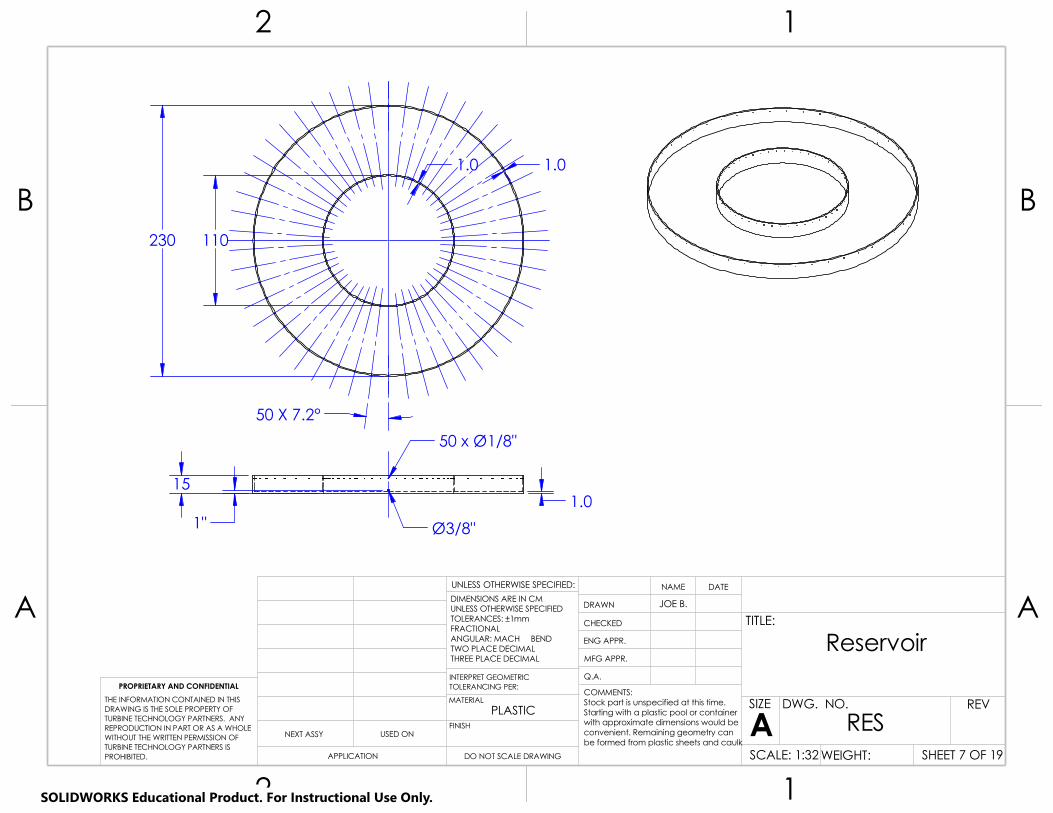
A A
B B
2
2
1
1
PLASTIC
Reservoir
DO NOT SCALE DRAWING
RESSHEET 7 OF 19
JOE B.
UNLESS OTHERWISE SPECIFIED:
SCALE: 1:32 WEIGHT:
REVDWG. NO.
ASIZE
TITLE:
NAME DATE
COMMENTS:Stock part is unspecified at this time.Starting with a plastic pool or containerwith approximate dimensions would beconvenient. Remaining geometry can be formed from plastic sheets and caulk
Q.A.
MFG APPR.
ENG APPR.
CHECKED
DRAWN
FINISH
MATERIAL
INTERPRET GEOMETRICTOLERANCING PER:
DIMENSIONS ARE IN CMUNLESS OTHERWISE SPECIFIEDTOLERANCES: ±1mmFRACTIONALANGULAR: MACH BEND TWO PLACE DECIMAL THREE PLACE DECIMAL
APPLICATION
USED ONNEXT ASSY
PROPRIETARY AND CONFIDENTIAL
THE INFORMATION CONTAINED IN THISDRAWING IS THE SOLE PROPERTY OFTURBINE TECHNOLOGY PARTNERS. ANY REPRODUCTION IN PART OR AS A WHOLEWITHOUT THE WRITTEN PERMISSION OFTURBINE TECHNOLOGY PARTNERS IS PROHIBITED.
50 x Ø1/8"
1"
15
Ø3/8"
1.0
230 110
1.0 1.0
50 X 7.2°
SOLIDWORKS Educational Product. For Instructional Use Only.
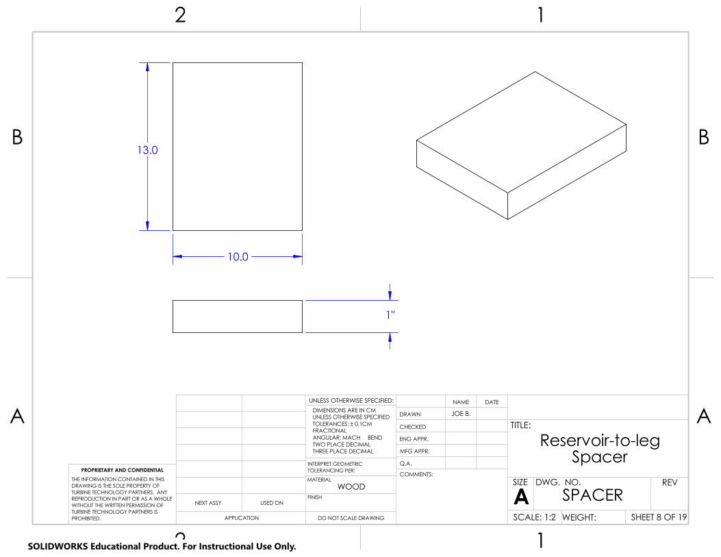
A A
B B
2
2
1
1
WOOD
Reservoir-to-leg Spacer
DO NOT SCALE DRAWING
SPACERSHEET 8 OF 19
JOE B.
UNLESS OTHERWISE SPECIFIED:
SCALE: 1:2 WEIGHT:
REVDWG. NO.
ASIZE
TITLE:
NAME DATE
COMMENTS:
Q.A.
MFG APPR.
ENG APPR.
CHECKED
DRAWN
FINISH
MATERIAL
INTERPRET GEOMETRICTOLERANCING PER:
DIMENSIONS ARE IN CMUNLESS OTHERWISE SPECIFIEDTOLERANCES: ± 0.1CMFRACTIONALANGULAR: MACH BEND TWO PLACE DECIMAL THREE PLACE DECIMAL
APPLICATION
USED ONNEXT ASSY
PROPRIETARY AND CONFIDENTIAL
THE INFORMATION CONTAINED IN THISDRAWING IS THE SOLE PROPERTY OFTURBINE TECHNOLOGY PARTNERS. ANY REPRODUCTION IN PART OR AS A WHOLEWITHOUT THE WRITTEN PERMISSION OFTURBINE TECHNOLOGY PARTNERS IS PROHIBITED.
1"
13.0
10.0
SOLIDWORKS Educational Product. For Instructional Use Only.

A A
B B
2
2
1
1
Leg Foot
DO NOT SCALE DRAWING
FOOTSHEET 9 OF 19
JOE B.
UNLESS OTHERWISE SPECIFIED:
SCALE: 1:2 WEIGHT:
REVDWG. NO.
ASIZE
TITLE:
NAME DATE
COMMENTS:Stock is part # 4698T133from McMaster-Carr
Q.A.
MFG APPR.
ENG APPR.
CHECKED
DRAWN
FINISH
MATERIAL
INTERPRET GEOMETRICTOLERANCING PER:
DIMENSIONS ARE IN CMUNLESS OTHERWISE SPECIFIEDTOLERANCES: ±0.01cmFRACTIONALANGULAR: MACH BEND TWO PLACE DECIMAL THREE PLACE DECIMAL
APPLICATION
USED ONNEXT ASSY
PROPRIETARY AND CONFIDENTIAL
THE INFORMATION CONTAINED IN THISDRAWING IS THE SOLE PROPERTY OFTURBINE TECHNOLOGY PARTNERS. ANY REPRODUCTION IN PART OR AS A WHOLEWITHOUT THE WRITTEN PERMISSION OFTURBINE TECHNOLOGY PARTNERS IS PROHIBITED.
1.50"
Ø1/2"
2.08
SOLIDWORKS Educational Product. For Instructional Use Only.

A A
B B
2
2
1
1
Galvanized Steel
Leg 1" pipe, 52" long
DO NOT SCALE DRAWING
PIPE 52SHEET 10 OF 19
JOE B.
UNLESS OTHERWISE SPECIFIED:
SCALE: 1:20 WEIGHT:
REVDWG. NO.
ASIZE
TITLE:
NAME DATE
COMMENTS:Stock part is 4499K54from McMaster-Carr
Q.A.
MFG APPR.
ENG APPR.
CHECKED
DRAWN
FINISH
MATERIAL
INTERPRET GEOMETRICTOLERANCING PER:
DIMENSIONS ARE IN INCHESUNLESS OTHERWISE SPECIFIEDTOLERANCES: ±0.05"FRACTIONALANGULAR: MACH BEND TWO PLACE DECIMAL THREE PLACE DECIMAL
APPLICATION
USED ONNEXT ASSY
PROPRIETARY AND CONFIDENTIAL
THE INFORMATION CONTAINED IN THISDRAWING IS THE SOLE PROPERTY OFTURBINE TECHNOLOGY PARTNERS. ANY REPRODUCTION IN PART OR AS A WHOLEWITHOUT THE WRITTEN PERMISSION OFTURBINE TECHNOLOGY PARTNERS IS PROHIBITED.
52.0"
SOLIDWORKS Educational Product. For Instructional Use Only.

A A
B B
2
2
1
1
Galvanized Steel
Leg 1" pipe, 6" long
DO NOT SCALE DRAWING
PIPE 6SHEET 11 OF 19
JOE B.
UNLESS OTHERWISE SPECIFIED:
SCALE: 1:2 WEIGHT:
REVDWG. NO.
ASIZE
TITLE:
NAME DATE
COMMENTS:Stock part is 4549K621from McMaster-Carr
Q.A.
MFG APPR.
ENG APPR.
CHECKED
DRAWN
FINISH
MATERIAL
INTERPRET GEOMETRICTOLERANCING PER:
DIMENSIONS ARE IN INCHESUNLESS OTHERWISE SPECIFIEDTOLERANCES: ±0.05"FRACTIONALANGULAR: MACH BEND TWO PLACE DECIMAL THREE PLACE DECIMAL
APPLICATION
USED ONNEXT ASSY
PROPRIETARY AND CONFIDENTIAL
THE INFORMATION CONTAINED IN THISDRAWING IS THE SOLE PROPERTY OFTURBINE TECHNOLOGY PARTNERS. ANY REPRODUCTION IN PART OR AS A WHOLEWITHOUT THE WRITTEN PERMISSION OFTURBINE TECHNOLOGY PARTNERS IS PROHIBITED.
1.50"
Ø1/2"
1.67
SOLIDWORKS Educational Product. For Instructional Use Only.

30° 30°
1.75"
1.75"
A A
B B
2
2
1
1
Zinc-plated Steel
Strut 1
DO NOT SCALE DRAWING
STRUT 1SHEET 12 OF 19
JOE B.
UNLESS OTHERWISE SPECIFIED:
SCALE: 1:25 WEIGHT:
REVDWG. NO.
ASIZE
TITLE:
NAME DATE
COMMENTS:Stock part is 3147T1from McMaster-Carr
Q.A.
MFG APPR.
ENG APPR.
CHECKED
DRAWN
FINISH
MATERIAL
INTERPRET GEOMETRICTOLERANCING PER:
DIMENSIONS ARE IN CMUNLESS OTHERWISE SPECIFIEDTOLERANCES: ±0.05cm, ±0.01inFRACTIONALANGULAR: MACH BEND TWO PLACE DECIMAL THREE PLACE DECIMAL
APPLICATION
USED ONNEXT ASSY
PROPRIETARY AND CONFIDENTIAL
THE INFORMATION CONTAINED IN THISDRAWING IS THE SOLE PROPERTY OFTURBINE TECHNOLOGY PARTNERS. ANY REPRODUCTION IN PART OR AS A WHOLEWITHOUT THE WRITTEN PERMISSION OFTURBINE TECHNOLOGY PARTNERS IS PROHIBITED.
13/16"
4 X Ø5/8"
4 X Ø13.5cm
90° 45°
3.50"
40.52°
43.51°
40.52°
43.51°
3.50" 13/16"
SOLIDWORKS Educational Product. For Instructional Use Only.

13/16"
A A
B B
2
2
1
1
Zinc-plated Steel
Strut 2
DO NOT SCALE DRAWING
STRUT 2SHEET 13 OF 19
JOE B.
UNLESS OTHERWISE SPECIFIED:
SCALE: 1:25 WEIGHT:
REVDWG. NO.
ASIZE
TITLE:
NAME DATE
COMMENTS:Stock part is 3147T1from McMaster-Carr
Q.A.
MFG APPR.
ENG APPR.
CHECKED
DRAWN
FINISH
MATERIAL
INTERPRET GEOMETRICTOLERANCING PER:
DIMENSIONS ARE IN CMUNLESS OTHERWISE SPECIFIEDTOLERANCES: ±0.05cm, ±0.01inFRACTIONALANGULAR: MACH BEND TWO PLACE DECIMAL THREE PLACE DECIMAL
APPLICATION
USED ONNEXT ASSY
PROPRIETARY AND CONFIDENTIAL
THE INFORMATION CONTAINED IN THISDRAWING IS THE SOLE PROPERTY OFTURBINE TECHNOLOGY PARTNERS. ANY REPRODUCTION IN PART OR AS A WHOLEWITHOUT THE WRITTEN PERMISSION OFTURBINE TECHNOLOGY PARTNERS IS PROHIBITED.
4 X Ø5/8"
40.52°
43.51°
40.52°
43.51°
1.75" 3.50"
2 X Ø1.35cm
90°
45°
13/16"
SOLIDWORKS Educational Product. For Instructional Use Only.

A A
B B
2
2
1
1
Zinc-plated Steel
Inner Strut Bracket
DO NOT SCALE DRAWING
INNERSHEET 14 OF 19
JOE B.
UNLESS OTHERWISE SPECIFIED:
SCALE: 1:2 WEIGHT:
REVDWG. NO.
ASIZE
TITLE:
NAME DATE
COMMENTS:Stock part is 33125T126from McMaster-Carr
Q.A.
MFG APPR.
ENG APPR.
CHECKED
DRAWN
FINISH
MATERIAL
INTERPRET GEOMETRICTOLERANCING PER:
DIMENSIONS ARE IN CMUNLESS OTHERWISE SPECIFIEDTOLERANCES: ±0.1cmFRACTIONALANGULAR: MACH BEND TWO PLACE DECIMAL THREE PLACE DECIMAL
APPLICATION
USED ONNEXT ASSY
PROPRIETARY AND CONFIDENTIAL
THE INFORMATION CONTAINED IN THISDRAWING IS THE SOLE PROPERTY OFTURBINE TECHNOLOGY PARTNERS. ANY REPRODUCTION IN PART OR AS A WHOLEWITHOUT THE WRITTEN PERMISSION OFTURBINE TECHNOLOGY PARTNERS IS PROHIBITED.
R91.44
SOLIDWORKS Educational Product. For Instructional Use Only.

A A
B B
2
2
1
1
Zinc-plated Steel
Outer Strut Bracket
DO NOT SCALE DRAWING
OUTERSHEET 15 OF 19
JOE B.
UNLESS OTHERWISE SPECIFIED:
SCALE: 1:2 WEIGHT:
REVDWG. NO.
ASIZE
TITLE:
NAME DATE
COMMENTS:Stock part is 33125T126from McMaster-Carr
Q.A.
MFG APPR.
ENG APPR.
CHECKED
DRAWN
FINISH
MATERIAL
INTERPRET GEOMETRICTOLERANCING PER:
DIMENSIONS ARE IN CMUNLESS OTHERWISE SPECIFIEDTOLERANCES: ±0.1FRACTIONALANGULAR: MACH BEND TWO PLACE DECIMAL THREE PLACE DECIMAL
APPLICATION
USED ONNEXT ASSY
PROPRIETARY AND CONFIDENTIAL
THE INFORMATION CONTAINED IN THISDRAWING IS THE SOLE PROPERTY OFTURBINE TECHNOLOGY PARTNERS. ANY REPRODUCTION IN PART OR AS A WHOLEWITHOUT THE WRITTEN PERMISSION OFTURBINE TECHNOLOGY PARTNERS IS PROHIBITED.
R95.57
SOLIDWORKS Educational Product. For Instructional Use Only.

A A
B B
2
2
1
1
PVC
Dropper PVC Pipe
DO NOT SCALE DRAWING
D PVCSHEET 16 OF 19
JOE B.
UNLESS OTHERWISE SPECIFIED:
SCALE: 1:5 WEIGHT:
REVDWG. NO.
ASIZE
TITLE:
NAME DATE
COMMENTS:Stock part is 49887from ACE Hardware
Q.A.
MFG APPR.
ENG APPR.
CHECKED
DRAWN
FINISH
MATERIAL
INTERPRET GEOMETRICTOLERANCING PER:
DIMENSIONS ARE IN CMUNLESS OTHERWISE SPECIFIEDTOLERANCES: ±0.05CMFRACTIONALANGULAR: MACH BEND TWO PLACE DECIMAL THREE PLACE DECIMAL
APPLICATION
USED ONNEXT ASSY
PROPRIETARY AND CONFIDENTIAL
THE INFORMATION CONTAINED IN THISDRAWING IS THE SOLE PROPERTY OFTURBINE TECHNOLOGY PARTNERS. ANY REPRODUCTION IN PART OR AS A WHOLEWITHOUT THE WRITTEN PERMISSION OFTURBINE TECHNOLOGY PARTNERS IS PROHIBITED.
0.50
19X1.00
22.00
20X#10-320.75 deep
1.06
SOLIDWORKS Educational Product. For Instructional Use Only.

A A
B B
2
2
1
1
Zinc-Plated Steel
Strut Mount for Droppers
DO NOT SCALE DRAWING
D MOUNTSHEET 17 OF 19
JOE B.
UNLESS OTHERWISE SPECIFIED:
SCALE: 1:1 WEIGHT:
REVDWG. NO.
ASIZE
TITLE:
NAME DATE
COMMENTS:Stock part is 3545T17from McMaster-Carr
Q.A.
MFG APPR.
ENG APPR.
CHECKED
DRAWN
FINISH
MATERIAL
INTERPRET GEOMETRICTOLERANCING PER:
DIMENSIONS ARE IN CMUNLESS OTHERWISE SPECIFIEDTOLERANCES: ±0.05cmFRACTIONALANGULAR: MACH BEND TWO PLACE DECIMAL THREE PLACE DECIMAL
APPLICATION
USED ONNEXT ASSY
PROPRIETARY AND CONFIDENTIAL
THE INFORMATION CONTAINED IN THISDRAWING IS THE SOLE PROPERTY OFTURBINE TECHNOLOGY PARTNERS. ANY REPRODUCTION IN PART OR AS A WHOLEWITHOUT THE WRITTEN PERMISSION OFTURBINE TECHNOLOGY PARTNERS IS PROHIBITED.
1.12
2.06
2.22
1.00 1.00
1.00 1.00
Ø0.69
5 X Ø0.80
SOLIDWORKS Educational Product. For Instructional Use Only.

A A
B B
2
2
1
1
6061 Aluminum
1:12 Flow Divider Body
DO NOT SCALE DRAWING
SPLITTERSHEET 18 OF 19
JOE B.
UNLESS OTHERWISE SPECIFIED:
SCALE: 1:1 WEIGHT:
REVDWG. NO.
ASIZE
TITLE:
NAME DATE
COMMENTS:Stock part is 8974K88from McMaster-Carr
Q.A.
MFG APPR.
ENG APPR.
CHECKED
DRAWN
FINISH
MATERIAL
INTERPRET GEOMETRICTOLERANCING PER:
DIMENSIONS ARE IN CMUNLESS OTHERWISE SPECIFIEDTOLERANCES: ±0.05cmFRACTIONALANGULAR: MACH BEND TWO PLACE DECIMAL THREE PLACE DECIMAL
APPLICATION
USED ONNEXT ASSY
PROPRIETARY AND CONFIDENTIAL
THE INFORMATION CONTAINED IN THISDRAWING IS THE SOLE PROPERTY OFTURBINE TECHNOLOGY PARTNERS. ANY REPRODUCTION IN PART OR AS A WHOLEWITHOUT THE WRITTEN PERMISSION OFTURBINE TECHNOLOGY PARTNERS IS PROHIBITED.
1/4 NPT
12 X 1/4 NPT1.75" deep
0.50"
SOLIDWORKS Educational Product. For Instructional Use Only.

A A
B B
2
2
1
1
PVC
3/4" PVC Rail
DO NOT SCALE DRAWING
RAILSHEET 19 OF 19
JOE B.
UNLESS OTHERWISE SPECIFIED:
SCALE: 1:25 WEIGHT:
REVDWG. NO.
ASIZE
TITLE:
NAME DATE
COMMENTS:Stock part is 48925K12from McMaster-Carr
Q.A.
MFG APPR.
ENG APPR.
CHECKED
DRAWN
FINISH
MATERIAL
INTERPRET GEOMETRICTOLERANCING PER:
DIMENSIONS ARE IN CMUNLESS OTHERWISE SPECIFIEDTOLERANCES: ±0.1cmFRACTIONALANGULAR: MACH BEND TWO PLACE DECIMAL THREE PLACE DECIMAL
APPLICATION
USED ONNEXT ASSY
PROPRIETARY AND CONFIDENTIAL
THE INFORMATION CONTAINED IN THISDRAWING IS THE SOLE PROPERTY OFTURBINE TECHNOLOGY PARTNERS. ANY REPRODUCTION IN PART OR AS A WHOLEWITHOUT THE WRITTEN PERMISSION OFTURBINE TECHNOLOGY PARTNERS IS PROHIBITED.
276.9
SOLIDWORKS Educational Product. For Instructional Use Only.

COMMENTS:
SCALE: 1:16
A A
B B
2
2
1
1
BEND
Assembly
DO NOT SCALE DRAWING SHEET 1 OF 1
11/19/20TH
DWG. NO.
UNLESS OTHERWISE SPECIFIED:
WEIGHT:
REV
Rotating bladeASIZE
TITLE:
NAME
VariesAll part numbers refer to McMaster
THREE PLACE DECIMAL TWO PLACE DECIMAL
information
Q.A.
MFG APPR.
ENG APPR.
CHECKED
DRAWN
VariesFINISH
Carr parts. Indented BOM has further MATERIAL
Exploded
USED ON
DATE
APPLICATION
INTERPRET GEOMETRICPROPRIETARY AND CONFIDENTIAL TOLERANCING PER:
NEXT ASSY
DIMENSIONS ARE IN INCHESTOLERANCES:FRACTIONALANGULAR: MACH
THE INFORMATION CONTAINED IN THISDRAWING IS THE SOLE PROPERTY OF<INSERT COMPANY NAME HERE>. ANY REPRODUCTION IN PART OR AS A WHOLEWITHOUT THE WRITTEN PERMISSION OF<INSERT COMPANY NAME HERE> IS PROHIBITED.
9.
10.
8.11.
2.1.
3.
4.
5.
6.
12.
ITEM NO.
PART NUMBER QTY.
1 ME 430 Rotor Disk 1
2 ME 430 Airfoil 3
3ME 430 Blade Sheath
3
4 96144A130 65 90854A382 126 90591A240 127 9859T417 18 Motor Stand In
(to size) 19 ME 430 I-Beam
Support 110 91257A749 611 94895A825 612 ME 430 Base
Plate 1
7.
SOLIDWORKS Educational Product. For Instructional Use Only.
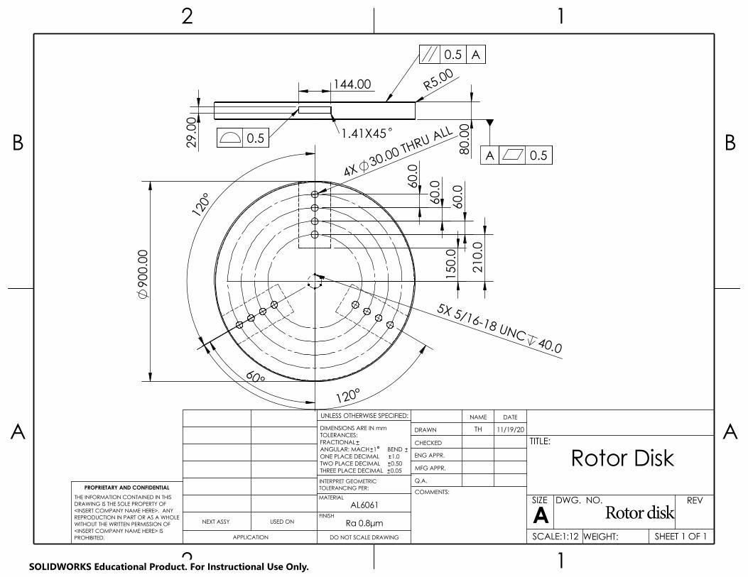
DWG. NO.
A A
B B
2
2
1
1
AL6061
Rotor Disk
DO NOT SCALE DRAWING
1.0
SHEET 1 OF 1
11/19/20TH
UNLESS OTHERWISE SPECIFIED:
Rotor diskWEIGHT:
REV
SCALE:1:12
ASIZE
TITLE:
NAME DATE
COMMENTS:
Q.A.
MFG APPR.
ENG APPR.
CHECKED
DRAWN
Ra 0.8μmFINISH
MATERIAL
TWO PLACE DECIMAL
TOLERANCING PER:INTERPRET GEOMETRIC
USED ON
0.500.05THREE PLACE DECIMAL
APPLICATION
NEXT ASSY
PROPRIETARY AND CONFIDENTIAL
DIMENSIONS ARE IN mmTOLERANCES:FRACTIONALANGULAR: MACH 1 BEND ONE PLACE DECIMAL
THE INFORMATION CONTAINED IN THISDRAWING IS THE SOLE PROPERTY OF<INSERT COMPANY NAME HERE>. ANY REPRODUCTION IN PART OR AS A WHOLEWITHOUT THE WRITTEN PERMISSION OF<INSERT COMPANY NAME HERE> IS PROHIBITED.
1.41X450.5
A
0.5
0.5
A
R5.00
80.
00
29.
00
144.00
60°
4X 30.00 THRU ALL
40.0
60.
0 60.
0
120
°
900.
00
60.
0 2
10.0
150
.0
5X 5/16-18 UNC
120°
SOLIDWORKS Educational Product. For Instructional Use Only.
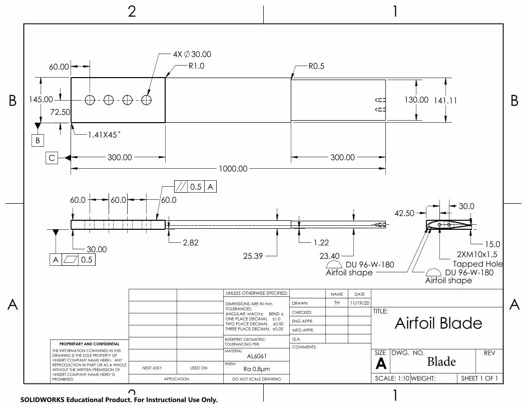
UNLESS OTHERWISE SPECIFIED:
A A
B B
2
2
1
1
AL6061
Airfoil Blade
DO NOT SCALE DRAWING
1.0
SHEET 1 OF 1
11/19/20TH
DWG. NO.Blade
WEIGHT:
REV
SCALE: 1:10
ASIZE
TITLE:
NAME DATE
COMMENTS:
Q.A.
MFG APPR.
ENG APPR.
CHECKED
DRAWN
Ra 0.8μmFINISH
MATERIAL
TWO PLACE DECIMAL
TOLERANCING PER:INTERPRET GEOMETRIC
0.050.50
APPLICATION
THREE PLACE DECIMAL
NEXT ASSY
PROPRIETARY AND CONFIDENTIAL
USED ON
DIMENSIONS ARE IN mmTOLERANCES:ANGULAR: MACH BEND ONE PLACE DECIMAL
THE INFORMATION CONTAINED IN THISDRAWING IS THE SOLE PROPERTY OF<INSERT COMPANY NAME HERE>. ANY REPRODUCTION IN PART OR AS A WHOLEWITHOUT THE WRITTEN PERMISSION OF<INSERT COMPANY NAME HERE> IS PROHIBITED.
0.5
R0.5
1.41X45
R1.0
B
C
4X 30.00
300.00 300.00 1000.00
141.11 130.00
60.00
145.00 72.50
A0.5
A
60.0
23.40 25.39 30.00
2.82 1.22
60.0 60.0
DU 96-W-180Airfoil shape DU 96-W-180
Airfoil shape
42.50
15.0
30.0
2XM10x1.5 Tapped Hole
SOLIDWORKS Educational Product. For Instructional Use Only.
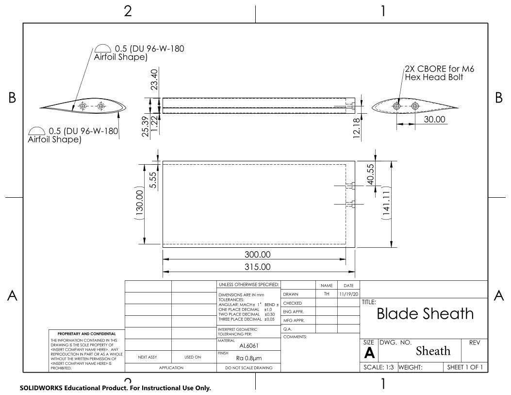
DWG. NO.
A A
B B
2
2
1
1
AL6061
Blade Sheath
DO NOT SCALE DRAWING
1.0
SHEET 1 OF 1
11/19/20TH
SCALE: 1:3
SheathWEIGHT:
REV
UNLESS OTHERWISE SPECIFIED:
ASIZE
TITLE:
NAME DATE
COMMENTS:
Q.A.
MFG APPR.
ENG APPR.
CHECKED
DRAWN
Ra 0.8μmFINISH
MATERIAL
TWO PLACE DECIMAL
TOLERANCING PER:INTERPRET GEOMETRIC
0.050.50
NEXT ASSY
THREE PLACE DECIMAL
APPLICATION
USED ON
PROPRIETARY AND CONFIDENTIAL
DIMENSIONS ARE IN mmTOLERANCES:ANGULAR: MACH 1 BEND ONE PLACE DECIMAL
THE INFORMATION CONTAINED IN THISDRAWING IS THE SOLE PROPERTY OF<INSERT COMPANY NAME HERE>. ANY REPRODUCTION IN PART OR AS A WHOLEWITHOUT THE WRITTEN PERMISSION OF<INSERT COMPANY NAME HERE> IS PROHIBITED.
130
.00
315.00 300.00
141
.11
40.
55
5.5
5
0.5 (DU 96-W-180Airfoil Shape)
0.5 (DU 96-W-180Airfoil Shape)
2X CBORE for M6 Hex Head Bolt
30.00
23.
40
25.
39
12.
18
1.2
2
SOLIDWORKS Educational Product. For Instructional Use Only.

USED ONNEXT ASSY
PROPRIETARY AND CONFIDENTIAL
Support
A A
B B
2
2
1
1
Structural Steel
I-Beam W14x90
DO NOT SCALE DRAWING
UNLESS OTHERWISE SPECIFIED:
SHEET 1 OF 1
11/19/20TH
DWG. NO.
.050
WEIGHT:
REV
SCALE: 1:10
ASIZE
TITLE:
NAME DATE
COMMENTS:
Q.A.
MFG APPR.
ENG APPR.
CHECKED
MATERIAL
INTERPRET GEOMETRIC
DRAWN
FINISH
TWO PLACE DECIMAL .005
TOLERANCING PER:
.010THREE PLACE DECIMAL
APPLICATION
DIMENSIONS ARE IN INCHESTOLERANCES:FRACTIONALANGULAR: MACH BEND ONE PLACE DECIMAL
THE INFORMATION CONTAINED IN THISDRAWING IS THE SOLE PROPERTY OF<INSERT COMPANY NAME HERE>. ANY REPRODUCTION IN PART OR AS A WHOLEWITHOUT THE WRITTEN PERMISSION OF<INSERT COMPANY NAME HERE> IS PROHIBITED.
A 23.6
0.0050.005 A
10.00 5.00
4.2
5
6X.53
4.1
2 4
.12
SOLIDWORKS Educational Product. For Instructional Use Only.
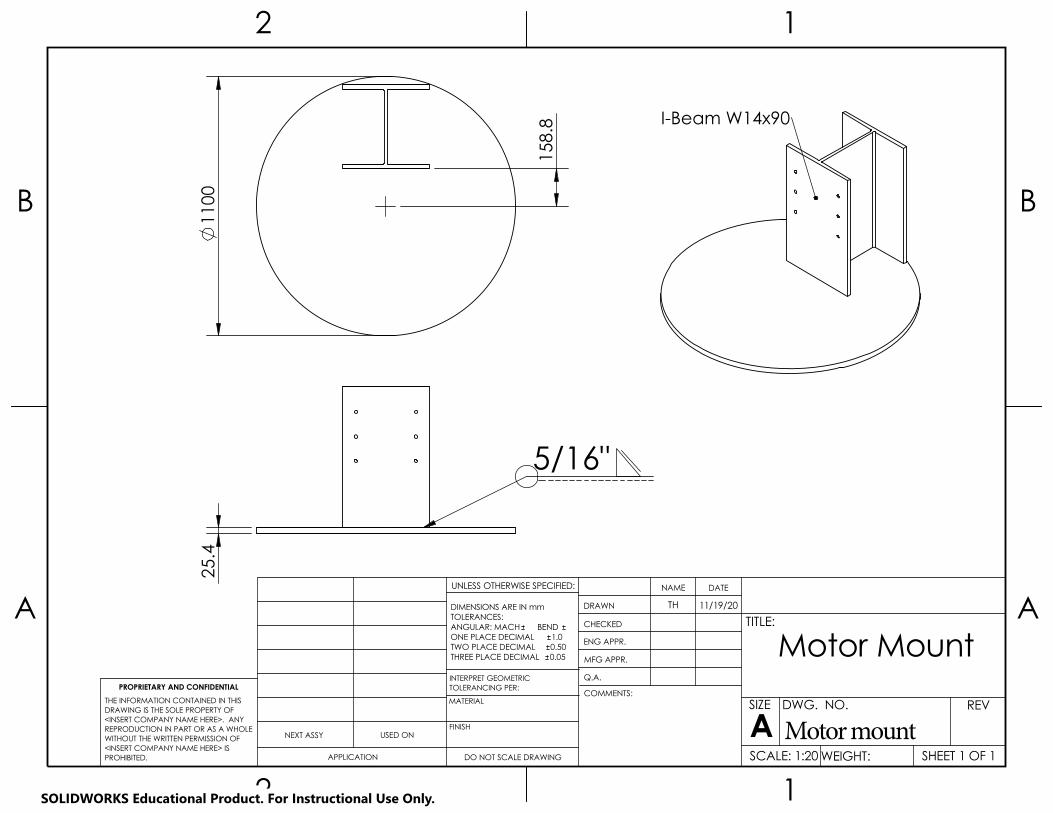
UNLESS OTHERWISE SPECIFIED:
A A
B B
2
2
1
1
Motor Mount
DO NOT SCALE DRAWING
1.0
SHEET 1 OF 1
11/19/20TH
DWG. NO.
Motor mountWEIGHT:
REV
SCALE: 1:20
ASIZE
TITLE:
NAME DATE
COMMENTS:
Q.A.
MFG APPR.
ENG APPR.
CHECKED
DRAWN
FINISH
PROPRIETARY AND CONFIDENTIAL
TWO PLACE DECIMAL
MATERIAL
INTERPRET GEOMETRIC
0.500.05THREE PLACE DECIMAL
USED ON
TOLERANCING PER:
NEXT ASSY
APPLICATION
DIMENSIONS ARE IN mmTOLERANCES:ANGULAR: MACH BEND ONE PLACE DECIMAL
THE INFORMATION CONTAINED IN THISDRAWING IS THE SOLE PROPERTY OF<INSERT COMPANY NAME HERE>. ANY REPRODUCTION IN PART OR AS A WHOLEWITHOUT THE WRITTEN PERMISSION OF<INSERT COMPANY NAME HERE> IS PROHIBITED.
1100
158
.8
5/16"
25.
4
I-Beam W14x90
SOLIDWORKS Educational Product. For Instructional Use Only.

Wind Turbine Erosion Testing Unit Group
Joe Blakewell, Tim Holt, Kevin Vartan
Operator’s Manual
Parts List for Rotating Blade System
# Part Part Description Count Image
1 Disk Central rotating hub that blades and motor connect to
1
2 Blade DU 96-W-180 aluminum airfoil 3
3 Sheath Sheath that fits on end of airfoil 3
4 Sheath Bolts
M6, 30mm long, fully threaded steel bolts
6
5 Blade Bolts
M30, 100mm long, fully threaded steel bolts
12
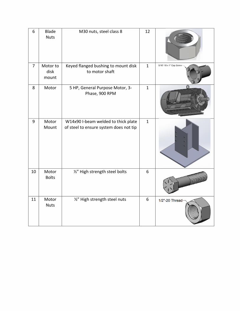
6 Blade Nuts
M30 nuts, steel class 8 12
7 Motor to
disk mount
Keyed flanged bushing to mount disk to motor shaft
1
8 Motor 5 HP, General Purpose Motor, 3-Phase, 900 RPM
1
9 Motor Mount
W14x90 I-beam welded to thick plate of steel to ensure system does not tip
1
10 Motor Bolts
½” High strength steel bolts 6
11 Motor
Nuts ½” High strength steel nuts 6

Parts List for Regular Fluid Delivery System Assembly
# Part Part Description Count Image
1 Reservoir Body
Hollow ring-shaped plastic pool 1
2 Curved Strut
and Connecting Hardware
Zinc-plated steel curved strut, ID = 3ft, 90 degree bend
4
3 Leg Assembly
and Hardware
1" steel pipe, 90 degree elbows, J-shaped with feet on ends 30mm m12 bolts with m12 washers and locknuts
6
4 Alignment
piece
Connects reservoir to legs 6
5 Peristaltic
Pump
Peristaltic pump, positive displacement
1

6 In-line Filter and tubing
Filters particles out of system before they reach the peristaltic pump. Tubing goes from reservoir to filter, and filter to peristaltic pump inlet.
1
7 Dropper
Bracket Assembly and
Hardware
Mounts around support ring and holds dropper nozzles connected by tubing
48
8 1:12 flow divider
6061 Aluminum disc-shaped, divides flow from 1 line into 12 equally. Tubing stretch 2 lines are pre-attached
4
9 Tubing stretch
1 ¼” flexible PVC plastic tubing from peristaltic pump outlet, through first two y-connectors, to inlet of 1:12 divider
1
10 Tubing stretch 2
¼" flexible PVC plastic tubing from outlet of 1:12 divider to inlet of Dropper Bracket Assembly
11 Leg-to-rail
crossover bracket
Attaches the rail that supports the curtain to the legs of the support structure.
6
12 ¾" PVC Pipe ¾" PVC pipe, 2.73m long 3
13 ¾" PVC Fittings 3
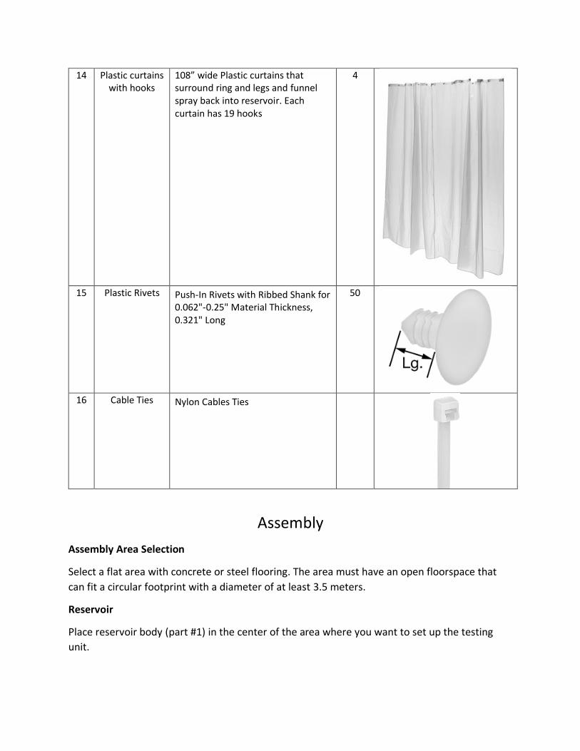
14 Plastic curtains with hooks
108” wide Plastic curtains that surround ring and legs and funnel spray back into reservoir. Each curtain has 19 hooks
4
15 Plastic Rivets Push-In Rivets with Ribbed Shank for
0.062"-0.25" Material Thickness, 0.321" Long
50
16 Cable Ties Nylon Cables Ties
Assembly
Assembly Area Selection
Select a flat area with concrete or steel flooring. The area must have an open floorspace that
can fit a circular footprint with a diameter of at least 3.5 meters.
Reservoir
Place reservoir body (part #1) in the center of the area where you want to set up the testing
unit.

Figure 1. Reservoir body
Rotating Blade System
Motor Mount
Following the steps to set up the base of the fluid delivery system, the user must first mount
the motor (8) to the floor of the testing room. They shall do this by bolting the steel plate with
motor mount welded to the plate into the floor in the center of the testing room. Once the
motor mount (9) is in place, mount the motor to it using 6 ½” high strength steel bolts (10) and
their corresponding nuts.
Figure 2. Motor mounted to floor

Disk Mounting
Once the motor is mounted to its mounting bracket, then bring in the disk (1). Using a minimum
of three people, place the disk on the shaft of the motor. Bolt the motor to the shaft using 5
5/16”-18 screws (7). Ensure that the disk is level using a spirit level.
Figure 3. Disk mounted to motor shaft
Blade Attachment
Once the disk is mounted and level, insert all three blades (2) simultaneously to ensure that the
disk does not become weighted off axis. After all three blades are inserted into their slots,
insert the largest bolts (5) through the disk and the blade and use the largest nuts (6) to tighten
them down to 1750 N•m.

Figure 4. Blade inserted into disk with first bolt and matching nut
Sheath Attachment
When the blades are inserted and bolted to the disk, the user may slide a sheath (3) over each
blade end and screw in the sheath bolts (4). Tighten these bolts down to 15 N•m. Each sheath
MUST have some form of LE protection on it so the aluminum sheath is not worn down.
Figure 5. Total assembly of rotating blade system

Fluid Delivery System Structure
Lay out the four curved strut pieces on the ground so that pairs of holes on the top of the struts
are all 60 degrees apart around the ring. Attach the curved struts together using the connecting
plates and hardware already on each strut to create the support ring.
Attach the short ends of the J-shaped legs (part #3) to the top of the assembled support ring
using the m12 hardware on the foot fitting. The channel of the struts face down and the legs
should be oriented outside of the ring. The final structure should look like the image below.
Figure 6. Support structure made up of ring and legs
Place alignment pieces (part #4) between the reservoir and each leg to ensure the structure is
centered with the reservoir.
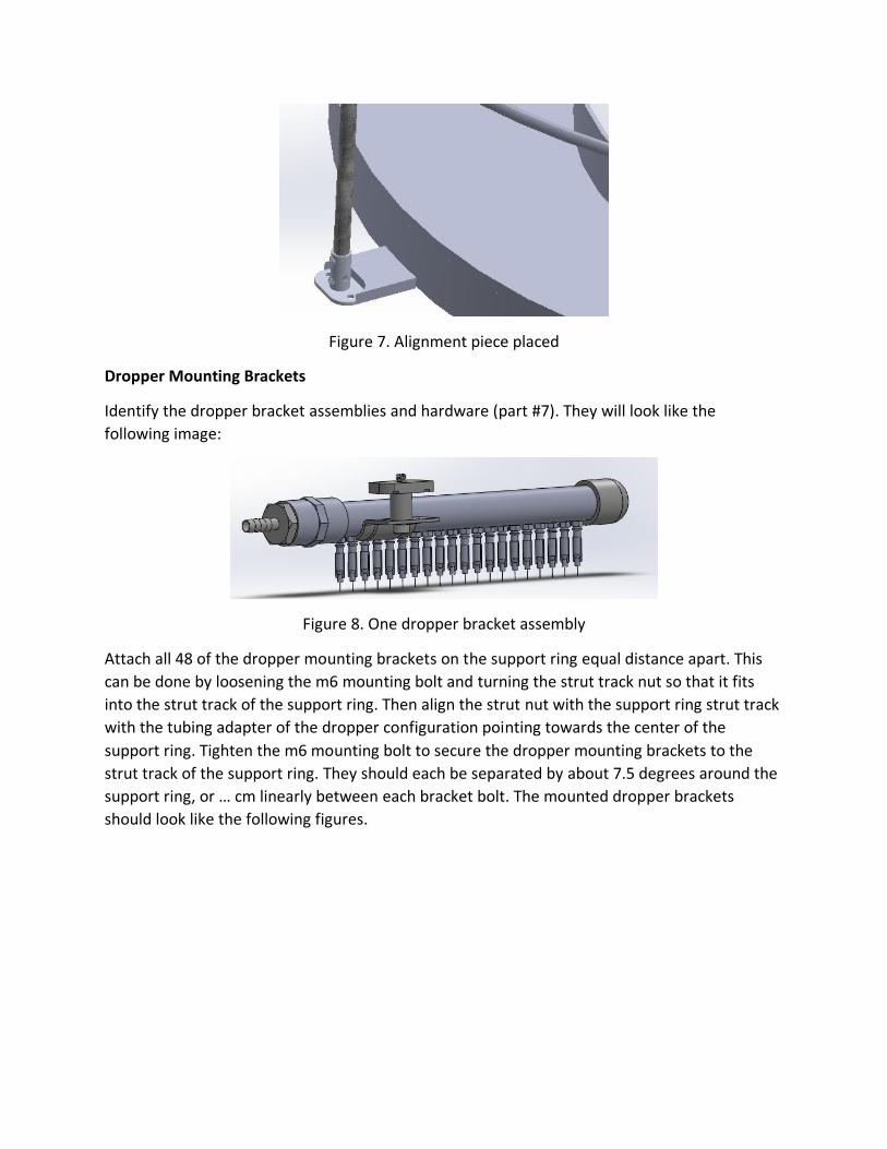
Figure 7. Alignment piece placed
Dropper Mounting Brackets
Identify the dropper bracket assemblies and hardware (part #7). They will look like the
following image:
Figure 8. One dropper bracket assembly
Attach all 48 of the dropper mounting brackets on the support ring equal distance apart. This
can be done by loosening the m6 mounting bolt and turning the strut track nut so that it fits
into the strut track of the support ring. Then align the strut nut with the support ring strut track
with the tubing adapter of the dropper configuration pointing towards the center of the
support ring. Tighten the m6 mounting bolt to secure the dropper mounting brackets to the
strut track of the support ring. They should each be separated by about 7.5 degrees around the
support ring, or … cm linearly between each bracket bolt. The mounted dropper brackets
should look like the following figures.

Figure 9. Close up of dropper mounting brackets on support ring
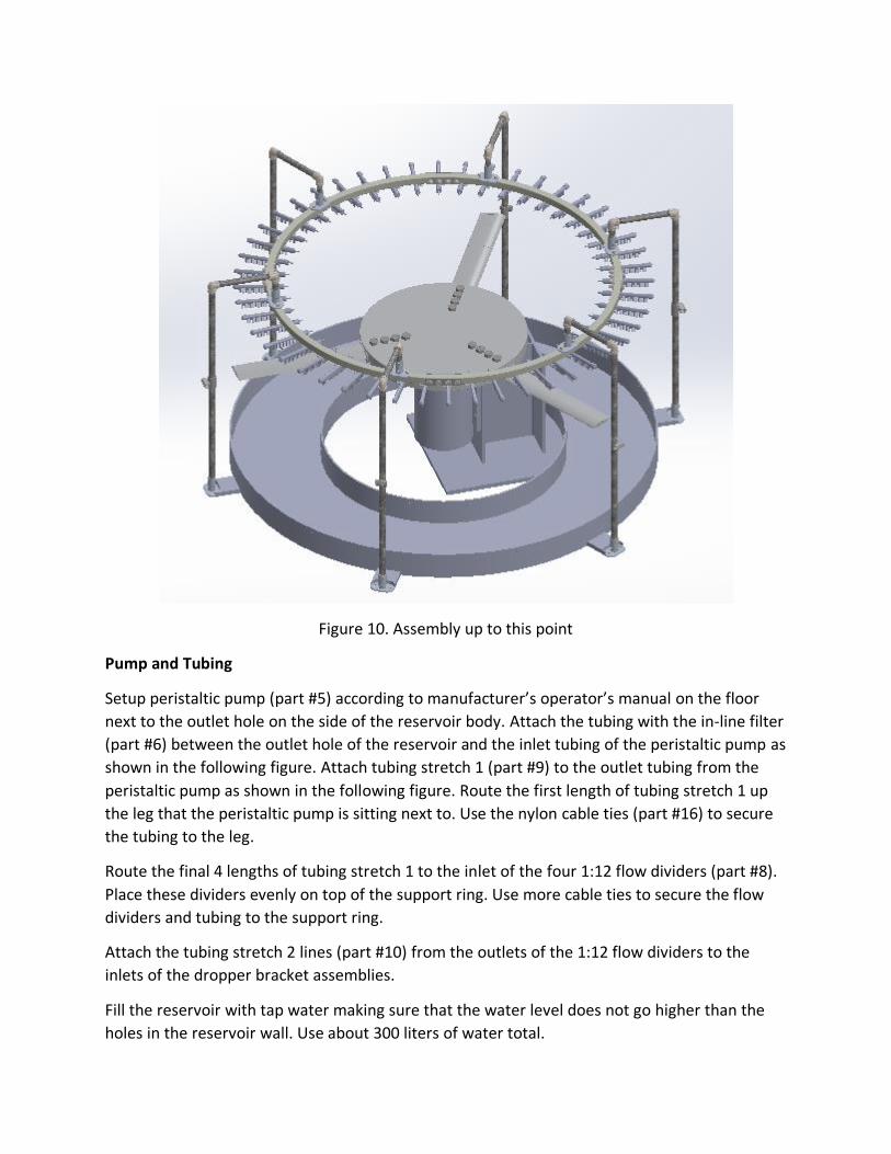
Figure 10. Assembly up to this point
Pump and Tubing
Setup peristaltic pump (part #5) according to manufacturer’s operator’s manual on the floor
next to the outlet hole on the side of the reservoir body. Attach the tubing with the in-line filter
(part #6) between the outlet hole of the reservoir and the inlet tubing of the peristaltic pump as
shown in the following figure. Attach tubing stretch 1 (part #9) to the outlet tubing from the
peristaltic pump as shown in the following figure. Route the first length of tubing stretch 1 up
the leg that the peristaltic pump is sitting next to. Use the nylon cable ties (part #16) to secure
the tubing to the leg.
Route the final 4 lengths of tubing stretch 1 to the inlet of the four 1:12 flow dividers (part #8).
Place these dividers evenly on top of the support ring. Use more cable ties to secure the flow
dividers and tubing to the support ring.
Attach the tubing stretch 2 lines (part #10) from the outlets of the 1:12 flow dividers to the
inlets of the dropper bracket assemblies.
Fill the reservoir with tap water making sure that the water level does not go higher than the
holes in the reservoir wall. Use about 300 liters of water total.

Slide the ¾" PVC pipe (part #12) through one of the crossover brackets mounted on the longest
part of the leg assembly. Bend the PVC pipe to fit it through the crossover bracket on the next
leg as well. Repeat this with the other two lengths of PVC pipe so that each crossover bracket
has PVC pipe going through it. Connect the loose ends of the PVC pipes with the ¾" PVC fittings
(part #13). This creates a rail for the curtain to be hung from.
Figure 11. Assembly up to this point not including tubing stretch 2
Hang the four curtains (part #14) from the PVC curtain rail so they completely surround the
assembly. Place the bottom of the curtains so they fall into the reservoir. Use the plastic rivets
(part #15) to secure the curtains to the inside wall of the reservoir. The curtains should be fairly
tight when they are attached to the reservoir wall.
Fluid Delivery System Operation
Once assembly is complete, follow peristaltic pump manufacturer’s operator’s manual to set
pump flowrate to 603 ml/min.
Watch for droppers to start producing drops. This could take up to 30 minutes. Ensure that all
droppers are producing drops at approximately the same rate. If any droppers are not

producing drops after 30 minutes, check dropper nozzles and tubing connections for pinches or
blockage. If pinches or blockage are found, turn off the pump and replace the faulty section of
tubing. Repeat this step after the replacement is made to ensure proper system function.
Rotating Blade System Operation
For operation of the Rotating Blade System, carefully check that all bolts are properly tightened.
Ensure that there are no pieces that are dangling from the Water Delivery System that might
interfere with the blade’s path. Clear all people but the operator from the room. Operator
follow the instructions from Worldwide Electric Corp. to turn on the PEWWE5-9-254T motor.
Operator must also then leave the room and allow the motor to spin up to speed.
Figure 12. Turbine Blade Erosion Testing Unit fully assembled not including tubing stretch 2 or
curtains