pore-based ridge reconstruction for fingerprint...
TRANSCRIPT

Pore-based ridge reconstruction for fingerprint recognition
Maurício Pamplona Segundo, Rubisley de Paula LemesIntelligent Vision Research Lab, Department of Computer Science, Federal University of Bahia, Brazil
{mauricio,rubisley}@dcc.ufba.br
Abstract
The use of sweat pores in fingerprint recognition is be-coming increasingly popular, mostly because of the wideavailability of pores, which provides complementary infor-mation for matching distorted or incomplete images. In thiswork we present a fully automatic pore-based fingerprintrecognition framework that combines both pores and ridgesto measure the similarity of two images. To obtain the ridgestructure, we propose a novel pore-based ridge reconstruc-tion approach by considering a connect-the-dots strategy.To this end, Kruskal’s minimum spanning tree algorithm isemployed to connect consecutive pores and form a graphrepresenting the ridge skeleton. We evaluate our frameworkon the PolyU HRF database, and the obtained results arefavorably compared to previous results in the literature.
1. IntroductionMost commercial Automatic Fingerprint Identification
Systems (AFIS) rely on Level 1 (i.e. global characteristics– ridge flow and pattern type) and Level 2 (i.e. local fea-tures – minutiae and ridge skeleton) features to distinguishgenuine and impostor individuals [5]. They achieve highrecognition accuracy, but depend on image quality to do so.For this reason, the use of Level 3 features (e.g. sweat poresand incipient ridges) as a complementary information formatching has attracted the attention of many researchers inthe literature. Among these features, the use of pores stoodout as a promising way to improve the recognition perfor-mance [5, 7, 8, 10, 13–15].
A pore-based AFIS usually has three main stages: (1)pore detection, (2) pore correspondence establishment and(3) similarity evaluation. Pore detection is a challengingtask since pores vary widely in size and shape (see Fig-ure 1). Some initial works [5, 15] did not adapt them-selves to such variations and, as a consequence, facedlarge numbers of false positives and false negatives. Otherworks [13, 14] addressed adaptability, but at the cost of us-ing computationally expensive techniques, such as ridge re-construction and frequency estimation. Recently, Lemes et
al. [7] proposed an accurate method, named Dynamic PoreFiltering (DPF), that efficiently adjusts itself to pore varia-tions without requiring these time-consuming calculations.
To establish pore correspondences, global alignment [5]or local pairwise correspondences [7, 8, 10, 14] can be con-sidered. The second one has become increasingly popularbecause keypoint description and matching is a very hottopic in computer vision research nowadays. There is anumber of descriptors that can be used to characterize pores(e.g. sparse representation [8], SIFT [10], DAISY [7]), andpore correspondences can be obtained by matching thosedescriptors. In this stage, an outlier filtering step is usuallynecessary to eliminate wrong correspondences.
Finally, a matching score is computed based on porecorrespondences and then employed to decide whether thematch is genuine or not. Typical score choices are the num-ber of correspondences [8, 14] or the average reprojectionerror [5]. This type of matching, however, does not con-sider how pores are related to each other, and consequentlymisses important pieces of information which could helpthe decision making process.
In this work, we present a fully automatic pore-based fin-gerprint recognition framework. Unlike other works in theliterature, we connect consecutive pores and use this infor-mation for matching as well. To perform the connectingtask, as our first contribution, we propose a novel ridge re-construction approach based on a connect-the-dots strategy.To this end, pores are interpreted as vertices of a graph andKruskal’s algorithm [6] is employed to find the minimumspanning tree that connects them. Then, as our second con-tribution, we present a pore-based matching approach thatalso takes the connection between pores in consideration.
2. Pore detectionSince we use pores for both ridge reconstruction and fin-
gerprint matching, we need a fast and accurate approach todetect them. To fulfill such requirements, we use DPF [7].
DPF has two main stages: (1) pore size estimation and(2) pore classification. To estimate the pore size, for eachpixel with value above a global threshold (i.e. bright pixel),the closest neighbor with value under the global threshold
1
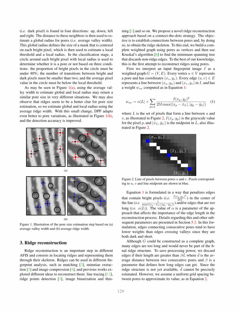
(i.e. dark pixel) is found in four directions: up, down, leftand right. The distance to these neighbors is then used to es-timate a global radius for pores (i.e. average valley width).This global radius defines the size of a mask that is centeredon each bright pixel, which is then used to estimate a localthreshold and a local radius. In the classification stage, acircle around each bright pixel with local radius is used todetermine whether it is a pore or not based on three condi-tions: the proportion of bright pixels in the circle must beunder 40%; the number of transitions between bright anddark pixels must be smaller than two; and the average pixelvalue in the circle must be below the local threshold.
As may be seen in Figure 1(a), using the average val-ley width to estimate global and local radius may return asimilar pore size in very different situations. We may alsoobserve that ridges seem to be a better clue for pore sizeestimation, so we estimate global and local radius using theaverage ridge width. With this small change, DPF adaptseven better to pore variations, as illustrated in Figure 1(b),and the detection accuracy is improved.
(a)
(b)
Figure 1. Illustration of the pore size estimation step based on (a)average valley width and (b) average ridge width.
3. Ridge reconstructionRidge reconstruction is an important step in different
AFIS and consists in locating ridges and representing themthrough their skeleton. Ridges can be used in different fin-gerprint analysis, such as matching [2], minutiae extrac-tion [5] and image compression [4], and previous works ex-plored different ideas to reconstruct them: line tracing [12],ridge points detection [3], image binarization and thin-
ning [1] and so on. We propose a novel ridge reconstructionapproach based on a connect-the-dots strategy. The objec-tive is to establish connections between pores and, by doingso, to obtain the ridge skeleton. To this end, we build a com-plete weighted graph using pores as vertices and then useKruskal’s algorithm [6] to find the minimum spanning treethat discards non-ridge edges. To the best of our knowledge,this is the first attempt to reconstruct ridges using pores.
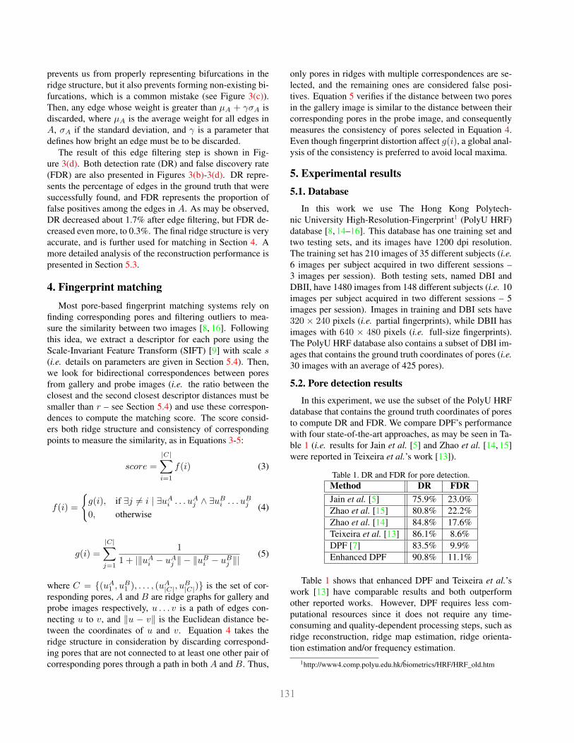
First we interpret an input fingerprint image I as aweighted graphG = (V,E). Every vertex u ∈ V representsa pore and has coordinates (xv, yv). Every edge (u, v) ∈ Erepresents a line between (xu, yu) and (xv, yv) in I , and hasa weight wuv computed as in Equation 1:
wuv = α|L|+∑p∈L
I(xp, yp)2
255 max(|xp − xL|, |yp − yL|)(1)
where L is the set of pixels that form a line between u andv, as illustrated in Figure 2, I(xp, yp) is the grayscale valuefor the pixel p, and (xL, yL) is the midpoint in L, also illus-trated in Figure 2.
Figure 2. Line of pixels between pores u and v. Pixels correspond-ing to u, v and line midpoint are shown in blue.
Equation 1 is formulated in a way that penalizes edgesthat contain bright pixels (i.e. I(xp,yp)2
255 ) in the center ofthe line (i.e. 1
max(|xp−xL|,|yp−yL|) ) and/or edges that are toolong (i.e. α|L|). The value of α is a parameter of the ap-proach that affects the importance of the edge length in thereconstruction process. Details regarding this and other sub-sequent parameters are presented in Section 5.3. In this for-mulation, edges connecting consecutive pores tend to havelower weights than edges crossing valleys since they areboth dark and short.
Although G could be constructed as a complete graph,many edges are too long and would never be part of the fi-nal ridge structure. To save processing power, we discardedges if their length are greater than βd, where d is the av-erage distance between two consecutive pores and β is aparameter that defines how long edges can get. Since theridge structure is not yet available, d cannot be preciselyestimated. However, we assume a uniform grid spacing be-tween pores to approximate its value, as in Equation 2.
2

(a) GROUND TRUTH (b) DR: 90.1% / FDR: 15.2% (c) DR: 99.1% / FDR: 6.7% (d) DR: 97.4% / FDR: 0.3%
Figure 3. Results of the proposed pore-based ridge reconstruction approach: (a) ground truth, ridge structure after running Kruskal’salgorithm in both (b) raw and (c) enhanced images; and (d) ridge structure after edge filtering. False positives are shown in red and falsenegatives are shown in blue. Edges in black were correctly detected by the proposed approach.
d ≈
√|V |
Irows ∗ Icols
−1
(2)
Finally, we run Kruskal’s algorithm and take the result-ing tree as the ridge structure. A pseudocode for Kruskal’salgorithm is provided in Algorithm 11, and, as may be ob-served, it is a greedy search that takes low-weight edges firstand removes all cycles in the graph. As edges between con-secutive pores have lower weights, they are frequently takenas part of the minimum spanning tree.
Algorithm 1: Kruskal’s minimum spanning tree.
Data: G(V,E)Result: A
1 A = ∅;2 forall the v ∈ V do3 setv = v;4 end5 sort E by wuv in increasing order;6 forall the (u, v) ∈ E do7 if setu 6= setv then8 A = A ∪ (u, v);9 merge setu and setv;
10 end11 end
An example of the ridge reconstruction result is shownin Figure 3(b). As may be seen, this initial result is veryfar from ideal, which is mainly caused by noise and con-trast changes in the fingerprint image. To reduce effects ofthese artifacts, we apply the Contrast Limited Adaptive His-togram Equalization (CLAHE) [11] to enhance image con-
trast. Using CLAHE, however, may end up sharpening thenoise (see Figure 4(b)). To avoid this, we apply a 3× 3 me-dian filter to the input image before applying CLAHE. Theresulting image is shown in Figure 4(c), and the improve-ment in ridge reconstruction results when using enhancedimages is presented in Figure 3(c).
(a) ORIGINAL (b) CLAHE (c) MEDIAN+CLAHE
Figure 4. Fingerprint image enhancement: (a) original image, andresult for CLAHE-based image enhancement (b) without and (c)with noise filtering.
After image enhancement, reconstruction results aremuch more visually sound, but many false positives (i.e.edges that should not be part of the ridge structure) are stillpresent. Most of them are selected in Algorithm 11 becausethe resulting tree must also be a connected graph, whichis not the case for a graph of a fingerprint image (see Fig-ure 3(a)). In addition, Kruskal’s algorithm has no infor-mation on how ridges are arranged, so it may over-connectvertices and/or select intersecting edges.
To overcome these problems, we specified some criteriato filter out false positives. First we created two rules toadd an edge (u, v) to A in Algorithm 11: (1) (u, v) can-not intersect any other edge already in A; and (2) neither uor v can already have two or more edges. The second rule
3
prevents us from properly representing bifurcations in theridge structure, but it also prevents forming non-existing bi-furcations, which is a common mistake (see Figure 3(c)).Then, any edge whose weight is greater than µA + γσA isdiscarded, where µA is the average weight for all edges inA, σA if the standard deviation, and γ is a parameter thatdefines how bright an edge must be to be discarded.
The result of this edge filtering step is shown in Fig-ure 3(d). Both detection rate (DR) and false discovery rate(FDR) are also presented in Figures 3(b)-3(d). DR repre-sents the percentage of edges in the ground truth that weresuccessfully found, and FDR represents the proportion offalse positives among the edges in A. As may be observed,DR decreased about 1.7% after edge filtering, but FDR de-creased even more, to 0.3%. The final ridge structure is veryaccurate, and is further used for matching in Section 4. Amore detailed analysis of the reconstruction performance ispresented in Section 5.3.
4. Fingerprint matchingMost pore-based fingerprint matching systems rely on
finding corresponding pores and filtering outliers to mea-sure the similarity between two images [8, 16]. Followingthis idea, we extract a descriptor for each pore using theScale-Invariant Feature Transform (SIFT) [9] with scale s(i.e. details on parameters are given in Section 5.4). Then,we look for bidirectional correspondences between poresfrom gallery and probe images (i.e. the ratio between theclosest and the second closest descriptor distances must besmaller than r – see Section 5.4) and use these correspon-dences to compute the matching score. The score consid-ers both ridge structure and consistency of correspondingpoints to measure the similarity, as in Equations 3-5:
score =
|C|∑i=1
f(i) (3)
f(i) =
{g(i), if ∃j 6= i | ∃uAi . . . uAj ∧ ∃uBi . . . uBj0, otherwise
(4)
g(i) =
|C|∑j=1
1
1 + |‖uAi − uAj ‖ − ‖uBi − uBj ‖|(5)
where C = {(uA1 , uB1 ), . . . , (uA|C|, uB|C|)} is the set of cor-
responding pores, A and B are ridge graphs for gallery andprobe images respectively, u . . . v is a path of edges con-necting u to v, and ‖u − v‖ is the Euclidean distance be-tween the coordinates of u and v. Equation 4 takes theridge structure in consideration by discarding correspond-ing pores that are not connected to at least one other pair ofcorresponding pores through a path in both A and B. Thus,
only pores in ridges with multiple correspondences are se-lected, and the remaining ones are considered false posi-tives. Equation 5 verifies if the distance between two poresin the gallery image is similar to the distance between theircorresponding pores in the probe image, and consequentlymeasures the consistency of pores selected in Equation 4.Even though fingerprint distortion affect g(i), a global anal-ysis of the consistency is preferred to avoid local maxima.
5. Experimental results5.1. Database
In this work we use The Hong Kong Polytech-nic University High-Resolution-Fingerprint1 (PolyU HRF)database [8, 14–16]. This database has one training set andtwo testing sets, and its images have 1200 dpi resolution.The training set has 210 images of 35 different subjects (i.e.6 images per subject acquired in two different sessions –3 images per session). Both testing sets, named DBI andDBII, have 1480 images from 148 different subjects (i.e. 10images per subject acquired in two different sessions – 5images per session). Images in training and DBI sets have320 × 240 pixels (i.e. partial fingerprints), while DBII hasimages with 640 × 480 pixels (i.e. full-size fingerprints).The PolyU HRF database also contains a subset of DBI im-ages that contains the ground truth coordinates of pores (i.e.30 images with an average of 425 pores).
5.2. Pore detection results
In this experiment, we use the subset of the PolyU HRFdatabase that contains the ground truth coordinates of poresto compute DR and FDR. We compare DPF’s performancewith four state-of-the-art approaches, as may be seen in Ta-ble 1 (i.e. results for Jain et al. [5] and Zhao et al. [14, 15]were reported in Teixeira et al.’s work [13]).
Table 1. DR and FDR for pore detection.Method DR FDRJain et al. [5] 75.9% 23.0%Zhao et al. [15] 80.8% 22.2%Zhao et al. [14] 84.8% 17.6%Teixeira et al. [13] 86.1% 8.6%DPF [7] 83.5% 9.9%Enhanced DPF 90.8% 11.1%
Table 1 shows that enhanced DPF and Teixeira et al.’swork [13] have comparable results and both outperformother reported works. However, DPF requires less com-putational resources since it does not require any time-consuming and quality-dependent processing steps, such asridge reconstruction, ridge map estimation, ridge orienta-tion estimation and/or frequency estimation.
1http://www4.comp.polyu.edu.hk/biometrics/HRF/HRF_old.htm
4

5.3. Ridge reconstruction results
To evaluate the accuracy of the proposed ridge recon-struction approach, we also use the subset of the PolyUHRF database that contains the ground truth coordinates ofpores. We extended the ground truth to include the ridgestructure of these images by manually marking valid edgesbetween annotated pores. An example of the extendedground truth is shown in Figure 3(a).
In our experiments, we run our approach using groundtruth pores and then compare the obtained reconstruction tothe ground truth graph. If an edge is present in the recon-struction result but is not in the ground truth, it is considereda false positive. If it is in the ground truth but is not in thereconstruction result, it is considered a false negative. Wecount the number of false positives and false negatives overthe entire test set to obtain both DR and FDR.
This experiment was repeated several times, and differ-ent values for α, β and γ were considered. α was testedover the range [0, 255] with step size 1, β over the range[1.0, 5.0] with step size 0.5, and γ over the range [1.0, 3.0]with step size 0.1. The best performance was obtained withα = 16, β = 2.5 and γ = 1.7, and the results are shown inTable 2. As may be observed, image enhancement and edgefiltering considerably reduce the number of false positivesand false negatives.
Table 2. DR and FDR for ridge reconstruction.Modality DR FDRRaw image 92.8% 13.1%Enhanced image 95.3% 10.8%Enhanced image + edge filtering 94.1% 3.9%
Finally, we use the best configuration found to recon-struct fingerprint ridges using automatically detected pores.This task is more challenging since we may have missingpores, pores detected multiple times, or false positives frompore detection. Figure 5(a) illustrates these problems andshows that the proposed approach is still able to providea meaningful interpretation of the ridge structure, althoughreconstruction results are better when the pore detection ismore accurate (see Figure 5(b)).
5.4. Matching results
Both pores and ridges were automatically extracted formatching. The training set of the PolyU HRF database wasused to find the parameter values that maximize the recog-nition accuracy of the proposed approach. SIFT scale s wastested over the range [1, 8] with step size 1, and threshold-ing ratio r over the range [0.1, 1.0] with step size 0.1. Thehighest recognition accuracy in the training set was obtainedwhen s = 4 and r = 0.8. These were then used unchangedin our experiments on DBI and DBII.
(a)
(b)
Figure 5. Pore-based ridge reconstruction results using (left)ground truth pores and (right) automatically detected pores.
We used the same methodology proposed by Liu etal. [8] to evaluate our matching performance on DBI andDBII. First we match images of the same subject in dif-ferent sessions to obtain the genuine score set (i.e. 3,700combinations). Then, we match the first image of each sub-ject in the first session to the first image of all other subjectsin the second session and obtain the impostor score set (i.e.21,756 combinations). The obtained scores are then usedto compute the Receiver Operating Characteristic (ROC)curve, which combines the False Rejection Rate (FRR) andthe False Acceptance Rate (FAR). The resulting curves forDBI and DBII are shown in Figure 6. Results for DBII arebetter than for DBI, as expected, since DBII images havefull-size fingerprints.
We also compared our results to other pore-based fin-gerprint recognition works in the literature. Table 3 showsthe Equal Error Rate (EER) for DBI and DBII usingMinutia and Pore alignment with Iterative Closest Points(MICPP) [5], Direct Pore matching (DP) [16], SparseRepresentation-based Direct Pore matching (SRDP) [8] andthe proposed approach (i.e. results for MICPP, DP andSRDP were reported in Liu et al.’s work [8]). As may beobserved, we reduced EER for DBI and DBII in more than
5

Figure 6. ROC curves of the proposed approach for DBI and DBII.
40% and 20%, respectively, when compared to the best re-sults in the literature. These results show the potential ofusing pore connections in pore-based fingerprint matchingand also validate the proposed pore-based ridge reconstruc-tion approach.
Table 3. EER for fingerprint matching using DBI and DBII.Approach DBI DBIIMICPP [5] 30.45% 7.83%DP [16] 15.42% 7.05%SRDP [8] 6.59% 0.97%Proposed 3.74% 0.76%
6. ConclusionWe propose a novel strategy to reconstruct fingerprint
ridges, which consists in connecting consecutive poresthrough edges to obtain the ridge skeleton. We also pro-pose an approach to automatically perform this reconstruc-tion based on Kruskal’s minimum spanning tree algorithm.To the best of our knowledge, this is the first attempt to re-construct ridges using pores. Our approach detects 94.1%of the ground truth edges with only 3.9% of false detections.
Then, we incorporate this ridge information in the pore-based matching stage in order to discard wrong pore corre-spondences. We achieve a 3.74% EER on DBI and a 0.76%EER on DBII, which outperform other works in the litera-ture. These results validates the proposed ridge reconstruc-tion approach, showing that the obtained ridge structure issuitable for fingerprint recognition.
The entire recognition framework does not rely onquality-dependent processing methods, making it wellsuited for distorted or damaged fingerprint images. As afuture work, we intend to investigate this issue and otheroptions for graph-based ridge matching (e.g. graph isomor-phism and maximum common subgraph).
AcknowledgmentsWe would like to thank the financial support from the
National Counsel of Technological and Scientific Develop-
ment (CNPq) and The Hong Kong Polytechnic Universityfor allowing access to the PolyU HRF database.
References[1] S. Chikkerur, A. N. Cartwright, and G. V. Fingerprint
enhancement using STFT analysis. Pattern Recognition,40(1):198–211, 2007. 2
[2] H. Choi, K. Choi, and J. Kim. Fingerprint matching incor-porating ridge features with minutiae. IEEE TIFS, 6(2):338–345, 2011. 2
[3] C. Domeniconi, S. Tari, and P. Liang. Direct gray scale ridgereconstruction in fingerprint images. In IEEE ICASSP, pages2941–2944, 1998. 2
[4] M. Gokmen, I. Ersoy, and A. Jain. Compression of finger-print images using hybrid image model. In IEEE ICIP, pages395–398, 1996. 2
[5] A. Jain, Y. Chen, and M. Demirkus. Pores and ridges: High-resolution fingerprint matching using level 3 features. IEEETPAMI, 29(1):15–27, 2007. 1, 2, 4, 5, 6
[6] J. B. Kruskal. On the Shortest Spanning Subtree of a Graphand the Traveling Salesman Problem. Proceedings of theAmerican Mathematical Society, 7(1):48–50, 1956. 1, 2
[7] R. Lemes, M. Pamplona Segundo, O. Bellon, and L. Silva.Dynamic pore filtering for keypoint detection applied tonewborn authentication. In IEEE ICPR, pages 1698–1703,2014. 1, 4
[8] F. Liu, Q. Zhao, D. Zhang, and D. Zhang. Fingerprint porematching based on sparse representation. In IEEE ICPR,pages 1630–1633, 2010. 1, 4, 5, 6
[9] D. G. Lowe. Object recognition from local scale-invariantfeatures. In IEEE ICCV, pages 1150–1157, 1999. 4
[10] S. Malathi and C. Meena. Improved partial fingerprintmatching based on score level fusion using pore and sift fea-tures. In IEEE PACC, pages 1–4, 2011. 1
[11] S. Pizer, R. Johnston, J. Ericksen, B. Yankaskas, andK. Muller. Contrast-limited adaptive histogram equalization:speed and effectiveness. In Proc. 1st Conference on Visual-ization in Biomedical Computing, pages 337–345, 1990. 3
[12] Y. Qi. Fingerprint ridge line reconstruction. In IntelligentInformation Processing II, volume 163 of IFIP, pages 211–220. Springer US, 2005. 2
[13] R. Teixeira and N. Leite. Improving pore extraction in highresolution fingerprint images using spatial analysis. In IEEEICIP, pages 4962–4966, 2014. 1, 4
[14] Q. Zhao, D. Zhang, L. Zhang, and N. Luo. Adaptive fin-gerprint pore modeling and extraction. Pattern Recognition,43(8):2833–2844, 2010. 1, 4
[15] Q. Zhao, D. Zhang, L. Zhang, and N. Luo. High resolu-tion partial fingerprint alignment using pore-valley descrip-tors. Pattern Recognition, 43(3):1050–1061, 2010. 1, 4
[16] Q. Zhao, L. Zhang, D. Zhang, and N. Luo. Direct porematching for fingerprint recognition. In Advances in Biomet-rics, volume 5558 of LNCS, pages 597–606. Springer BerlinHeidelberg, 2009. 4, 5, 6
6