pontifical catholic university of rio grande do … · pontifical catholic university of rio grande...
TRANSCRIPT

PONTIFICAL CATHOLIC UNIVERSITY OF RIO GRANDE DO SULDEPARTAMENT OF INFORMATICS
GRADUATE PROGRAMME IN COMPUTER SCIENCE
CROWDVIS: A FRAMEWORK FORREAL TIME CROWD VISUALIZATION
HENRY BRAUN
Dissertation presented as partial requirementfor obtaining the master’s degree in ComputerScience from Pontifical Catholic University ofRio Grande do Sul.
Adviser: Prof. Dr. Soraia Raupp Musse
Porto Alegre, Brazil2012


B825c Braun, Henry
Crowdvis: a framework for real time crowd visualization / Henry Braun. – Porto Alegre, 2012.
83 f.
Diss. (Mestrado) – Fac. de Informática, PUCRS. Orientador: Profª. Drª. Soraia Raupp Musse.
1. Informática. 2. Realidade Virtual. 3. Simulação e Modelagem
em Computadores. I. Musse, Soraia Raupp. II. Título. CDD 006.6
Ficha Catalográfica elaborada pelo
Setor de Tratamento da Informação da BC-PUCRS


“There must be a beginning of any great matter, but the continuing unto the enduntil it be thoroughly finished yields the true glory.”
Sir Francis Drake
“We cannot change the cards we are dealt, just how we play the hand. If I don’t seem asdepressed or morose as I should be, I’m sorry to disappoint you.”
Randy Pausch


ACKNOWLEDGMENTS
During this two year experience I had the opportunity to meet incredible people and tobe in extraordinary places. I want to specially thank my adviser Soraia Raupp Musse, whotrusted me in all the moments and helped me push my limits even further. Professors MarcioPinho, Marcelo Cohen and Christian Lykawka, thank you for helping me cross the bridge toget into the CG world. Professor Donald Marinelli, thank you for everything you have donefor me and the wonderful time at the Dream Fulfillment Factory.
My VHLab workmates, thank you all for listening to my metal musics without going nuts!Vinicius Cassol, thank you for your friendship and all the help! Rafael Rodrigues, RafaelHocevar, Fernando Marson, Humberto Souto, Adriana Braun, Juliano Moreira, CristinaScheibler, Luiz Cunha, Anderson Silva, Rossana Queiroz, Leandro Dihl and Julio Jacques,I am pretty sure that you guys are going to be successful at any place and at any time, keepup the good work.
My VRoom360 team, you guys know how much awesome you all are. Tim Forsythe,thank you for being an incredible leader. Anmol Nagpal and Dev Ghai, thank you for sharingyour amazing culture. Ping Li Andy, thank you for being supportive during all the moments.Samantha Collier, thank you for not punching me in the face. Terry, thank you for helping meout and showing me Pittsburgh! Pan, Mrs. Baby and Mr.Pepper, thank you for making mydays happier by your presence.
Swordtales team, thank you for the opportunity to work with such good talents. LuizAlvarez, Conrado Testa and Alessandro Martinello don’t give up on games.
Manuel Lopez, Breogan Amoedo and Marc Estruch, thank you for providing me shelterwhen I had nowhere to go and mostly for trusting me your friendship.
Priscila Wagner and Diogo Ribeiro, thank you for helping me out during bad times.Diogo Lima and Marcelo Paravisi, thank you my two brothers. For all the coding, listening,
explaining, gaming, drinking, supporting and for yelling at me when needed. EduardoMuccillo, thank you for all the chatting and good beers!
Juliana Pacheco, I love you. Thank you for everything, mainly for showing me how simplethings can be, and being there for me everyday.
My father Harold Braun, mother Norma Braun and family, thank you for being just theway you are, for providing everything I needed in life.
This work was made in collaboration with Hewlett-Packard Brazil R&D.


CROWDVIS: A FRAMEWORK FOR REAL TIME CROWD VISUALIZATION
ABSTRACT
Crowd visualizations are present mostly in digital games and computer animated movies, butthey are also observed in simulations and virtual reality applications. In crowd simulations weshould represent the behavior of agents given different scenarios, and also, such simulations can beprovided by different software and tools. This document describes a framework for real time crowdvisualization, which no programming knowledge and modeling skills are required from the users.Our main goal is to be able to visualize previously created crowd simulations in real time, combiningrendering techniques and providing easy support for managing the scene and the virtual humans.
Keywords: Crowd Visualization; Crowd Simulation; Virtual Humans; Reconstruction; Rendering;Level-Of-Detail; Special Effects.


CROWDVIS: UM FRAMEWORK PARA VISUALIZAÇÃO DE MULTIDÕESEM TEMPO REAL
RESUMO
Visualizações de multidões estão presentes principalmente em jogos digitais e filmes deanimação computadorizada. Essas visualizações também são observadas em simulações eaplicações de realidade virtual. Em modelos para simulações de multidões é preciso representaro comportamento dos agentes de acordo com os diferentes cenários, além disto, tais simulaçõespodem ser originadas de diferentes software ou ferramentas. Esta dissertação apresenta umframework para visualização de multidões em tempo real, a qual não requer conhecimentode programação e modelagem. O principal objetivo é apresentar visualizações de simulaçõespreviamente criadas, combinando o uso de técnicas de rendering em tempo real, além deproporcionar ferramentas para gerenciar a cena e os humanos virtuais.
Palavras-Chave: Visualização de Multidões; Simulação de Multidões; Humanos Virtuais;Reconstrução; Rendering em Tempo Real; Níveis De Detalhe; Efeitos Especiais.


LIST OF FIGURES
2.1 Thalmann’s and Beicheiraz [4] nonverbal communication model. . . . . . . . 252.2 Tavares model [43] using different somatotype values. . . . . . . . . . . . . . 272.3 Tecchia et al. [45] model for rendering real time crowds. . . . . . . . . . . . . 293.1 Overview of CrowdVis model. . . . . . . . . . . . . . . . . . . . . . . . . . . . 323.2 Hall’s proxemics distances illustration. . . . . . . . . . . . . . . . . . . . . . . 333.3 VHs interactions detected in our model. . . . . . . . . . . . . . . . . . . . . . 343.4 Ignored interaction case using our metrics. . . . . . . . . . . . . . . . . . . . 353.5 Regular animations of the three movement cases. . . . . . . . . . . . . . . . 363.6 Example of a VH’s orientation path. . . . . . . . . . . . . . . . . . . . . . . . . 383.7 Comparison between computed and desired paths. . . . . . . . . . . . . . . . 393.8 Screenplay animation provided by the user. . . . . . . . . . . . . . . . . . . . 403.9 Initial pipeline of VHs reconstruction. . . . . . . . . . . . . . . . . . . . . . . . 433.10 Automatic texture chunks obtained. . . . . . . . . . . . . . . . . . . . . . . . . 433.11 Binary silhouette and body parts width estimation for automatic reconstruction. 443.12 CrowdVis VH reconstruction interface. . . . . . . . . . . . . . . . . . . . . . . 443.13 Male and female template models. . . . . . . . . . . . . . . . . . . . . . . . . 453.14 Illustrations of reconstructed virtual humans without being stitched. . . . . . . 463.15 Template model without and with texture. . . . . . . . . . . . . . . . . . . . . 473.16 Default UV mapping and planar mapping. . . . . . . . . . . . . . . . . . . . . 473.17 VH reconstruction pipeline. . . . . . . . . . . . . . . . . . . . . . . . . . . . . 484.1 Heightmap image. . . . . . . . . . . . . . . . . . . . . . . . . . . . . . . . . . 504.2 Manipulation of scene assets and the interface. . . . . . . . . . . . . . . . . . 514.3 The three Levels-Of-Detail. . . . . . . . . . . . . . . . . . . . . . . . . . . . . 524.4 Virtual human lighting techniques. . . . . . . . . . . . . . . . . . . . . . . . . 534.5 Four textures of the 3072 impostor texture set. . . . . . . . . . . . . . . . . . 544.6 CrowVis approach for determining the best suitable animated impostor texture. 554.7 Exact same scene and camera view for 100 agents in two different renderings. 564.8 5000 animated impostors for large scale simulations. . . . . . . . . . . . . . . 564.9 Shadowing techniques present in Tomb Raider 4 games. . . . . . . . . . . . . 574.10 Shadowing techniques present in CrowdVis. . . . . . . . . . . . . . . . . . . . 584.11 Comparison between default and HDR rendering. . . . . . . . . . . . . . . . 594.12 Two examples of particle systems present in CrowdVis. . . . . . . . . . . . . 604.13 Some effects presented in CrowdVis prototype section. . . . . . . . . . . . . 615.1 Result of our model illustrating four steps. . . . . . . . . . . . . . . . . . . . . 635.2 Original picture and the generated VH. . . . . . . . . . . . . . . . . . . . . . . 64

5.3 Original picture and the generated VH in a virtual world. . . . . . . . . . . . . 645.4 A reconstructed virtual human among other virtual humans. . . . . . . . . . . 655.5 Virtual human executing screenplay animations. . . . . . . . . . . . . . . . . 655.6 A human interaction detected by CrowdVis Behavior Analysis module. . . . . 665.7 Another human interaction detected by CrowdVis Behavior Analysis. . . . . . 665.8 Evaluation of two different renderings. . . . . . . . . . . . . . . . . . . . . . . 675.9 Visualization of two simulation frames created using BioCrowds. . . . . . . . 695.10 Visualization of two simulation frames created using CrowdSim. . . . . . . . . 70A.1 Behavior Analysis module flowchart. . . . . . . . . . . . . . . . . . . . . . . . 80

LIST OF TABLES
1.1 Requeriments we believe it is essential for a crowd visualization. . . . . . . . 234.1 Number of agents, the amount of video memory used and the frame rate. . . 554.2 Evaluation the FPS using different camera distances. . . . . . . . . . . . . . 564.3 Impact on performance when using shadowing techniques. . . . . . . . . . . 584.4 Impact on performance when using the HDR technique. . . . . . . . . . . . . 595.1 Performance between CrowdVis and Unity 3D. . . . . . . . . . . . . . . . . . 665.2 CrowdVis frame rate according the number of agents. . . . . . . . . . . . . . 67


LIST OF ABBREVIATIONS
2D Two-Dimensional
3D Three-Dimensional
AI Artificial Intelligence
BVH Biovision Hierarchy
CG Computer Graphics
CPU Central Processing Unit
CVE Collaborative Virtual Environment
DOF Degrees-Of-Freedom
FOV Field-Of-View
FPS Frames Per Second
GPU Graphics Processing Unit
HDD Hard Disk Drive
HDR High Dynamic Range
IBR Image-Based Rendering
IK Inverse Kinematics
LOD Level-Of-Detail
VH Virtual Human
VR Virtual Reality
VRML Virtual Reality Modeling Language


SUMMARY
LIST OF FIGURES 13
LIST OF TABLES 15
LIST OF ABBREVIATIONS 17
1. INTRODUCTION 211.1 Objectives . . . . . . . . . . . . . . . . . . . . . . . . . . . . . . . . . . . . . . 221.2 Organization . . . . . . . . . . . . . . . . . . . . . . . . . . . . . . . . . . . . 23
2. RELATED WORK 252.1 Individual Behavior in Groups or Crowds . . . . . . . . . . . . . . . . . . . . . 252.2 Virtual Humans Reconstruction . . . . . . . . . . . . . . . . . . . . . . . . . . 262.3 Crowd Visualization . . . . . . . . . . . . . . . . . . . . . . . . . . . . . . . . 282.4 CrowdVis and the State-of-the-Art . . . . . . . . . . . . . . . . . . . . . . . . 29
3. THE CROWDVIS MODEL 313.1 Behavior Analysis Module . . . . . . . . . . . . . . . . . . . . . . . . . . . . . 31
3.1.1 Human Interactions . . . . . . . . . . . . . . . . . . . . . . . . . . . . 333.1.2 Human Motion . . . . . . . . . . . . . . . . . . . . . . . . . . . . . . . 363.1.3 Screenplay Animation . . . . . . . . . . . . . . . . . . . . . . . . . . . 40
3.2 Virtual Humans Reconstruction Module . . . . . . . . . . . . . . . . . . . . . 413.2.1 3D Pose Identification . . . . . . . . . . . . . . . . . . . . . . . . . . . 423.2.2 Human Segmentation . . . . . . . . . . . . . . . . . . . . . . . . . . . 423.2.3 Silhouette Processing . . . . . . . . . . . . . . . . . . . . . . . . . . . 433.2.4 Template Posing . . . . . . . . . . . . . . . . . . . . . . . . . . . . . . 443.2.5 Mesh Deformation . . . . . . . . . . . . . . . . . . . . . . . . . . . . . 463.2.6 Texturing . . . . . . . . . . . . . . . . . . . . . . . . . . . . . . . . . . 47
4. THE CROWDVIS PROTOTYPE 494.1 Audio-Visual Module . . . . . . . . . . . . . . . . . . . . . . . . . . . . . . . . 49
4.1.1 Environment . . . . . . . . . . . . . . . . . . . . . . . . . . . . . . . . 494.1.2 Virtual Humans . . . . . . . . . . . . . . . . . . . . . . . . . . . . . . . 52

4.1.3 Special Effects . . . . . . . . . . . . . . . . . . . . . . . . . . . . . . . 57
5. RESULTS 635.1 Virtual Humans Reconstruction . . . . . . . . . . . . . . . . . . . . . . . . . . 635.2 Crowd Visualization . . . . . . . . . . . . . . . . . . . . . . . . . . . . . . . . 64
5.2.1 Crowd Simulators . . . . . . . . . . . . . . . . . . . . . . . . . . . . . 67
6. FINAL CONSIDERATIONS 71
REFERENCES 73
Appendix A. Behavior Analysis Module 79
Appendix B. Publications 81

23
1. INTRODUCTION
Impressive game engines have become accessible to general users in the past fewyears. Engines such as Unity 3D 1 and Unreal Engine 2, among others, provide tools andmechanisms for displaying Three-Dimensional (3D) graphics and creating games. However,these and other engines are rarely focused on real time crowd visualization, besides that,such engines, require a certain set of programming skills and also artists to coherently createthe assets and the Virtual Humans (VHs) for visualizing crowds.
Crowd simulation is an area of Computer Graphics (CG) and, sometimes, ArtificialIntelligence (AI) concerned with the process of simulating a large number of virtual agents.Nowadays, crowd simulation is an important topic of research since it is crucial for someapplications as, for instance, in the fields of security, education and entertainment. Suchsimulations, as the number of 3D objects involved can be huge, are not trivial to render athigh resolution on standard computers and graphic cards [19].
Methods to simulate VHs and crowds are often mediated by local rules [31], forces[21], flows [48] or hybrid approaches [34]. Usually, these methods consider the agents assimplified geometries, such as points, spheres and cubes. These abstractions are importantto facilitate the usage of complex mathematical models. However, when the simulationsshould be visualized, some artifacts can be noticed, such as geometry intersections orissues regarding the VHs motion.
Examples of pioneer methods are Musse [31] and Helbing [21], which provide differentmodels for crowd simulation, that could be specific employed for different scenarios (e.g. asocial event or an evacuation situation). Normally, the simulation prototypes include theirown visualization module, which can limit the integration of different simulation models intheir visualization.
Isolating the simulation from the visualization may facilitate the creation process for theusers, as they can now be only concerned with the simulation model or with the visualization.Besides that, a dedicated visualization module could integrate several simulation modelsin order to create an unique scene, e.g. a specific model for small groups can simulatepeople inside buildings, while another model can simulate the crowd outside. Dedicatedvisualization modules can also improve realism (e.g. by the usage of embodied agents andbetter rendering), granting superior understanding of the simulation.
Improved visualization of crowds can be used for other purposes, such as entertainment,marketing, education or safety training systems. These applications usually require a certainset of features, such as load simulation files, provide support to embodied VHs and also
1http://www.unity3d.com2http://www.unreal.com

24 CHAPTER 1. INTRODUCTION
represent motion in a coherent way accordingly the simulation. The usage of virtual humansis essential, since the agents are important for several scenarios, as in games or VirtualReality (VR) applications, especially in virtual scenes that aims to realistically recreate thereal world [46].
In this work we present CrowdVis, a framework to be handled either by naive orexperienced users. The main goal is to provide tools and enable the users to visualize,in 3D environments, previously created crowd simulations. CrowdVis can reproduce thesimulations created by any source, by simply matching their output in our simulation inputformat. This approach can be used in order to create an unique visualization by combiningdifferent crowd simulation techniques. Moreover, CrowdVis assures that the simulation andthe visualization is conservative, i.e. the visualization represents exactly what is going onthe simulation.
Specifically, CrowdVis can create embodied agents, with animations as well, and proposevisual behaviors for agents interactions. This is motivated due to the fact that the gameindustry is always engaged in unraveling new gameplay experiences in order to providea deeper game immersion. One of these new experiences is by allowing the player touse her/his own appearance-like avatar while playing, presented in Electronic Arts Sports3
games (e.g. Fifa Soccer 20124).
1.1 Objectives
We propose a model for virtual humans, which includes the detection of possibleinteractions, techniques for a realistic motion and visually accepted reconstruction of VHsbased on a single Two-Dimensional (2D) image. The techniques presented in our modelcould be employed for different virtual worlds, such as games and movies. Besidesthis, CrowdVis prototype can generate visualizations that could be employed for differentpurposes. Some examples are listed bellow:
• a video for evacuation procedures illustrating the emergency exits;
• a video for entertainment purposes such as games or events; and
• a virtual walkthrough intended to show off buildings and houses, among others.
The main goal of CrowdVis is to provide a dedicated framework for real time visualizationof crowd simulations. The main idea is to provide total control for the user, requiring noprogramming experience, capable to visualize previously created simulations using customVHs and/or the ones created by the reconstruction model. Moreover, CrowdVis also
3http://www.ea.com/games4http://www.ea.com/soccer/fifa

1.2. ORGANIZATION 25
presents tools for animation, special effects, environment management, behavior control,VHs reconstruction and illumination. Table 1.1 organizes in a list requeriments we believe itis essential for a crowd visualization framework to attend.
Table 1.1 – A list of requeriments we believe it is essential for a crowd visualization frameworkto attend.
Name DescriptionVirtual Humans Support To be fully capable of using customs VHs, a set of default
ones or provide an easy way to create VHs on the fly.Environment Support To be fully capable of loading and manipulating the scene
assets and its illumination.Crowd Simulation Support To manipulate the simulation playback, visualize paths and
play simultanslesly simulations at the same visualization.Realism Features To provide animation blendings, environmental virtual
humans, advanced lightning, detect and be able to displayinteractions between VHs.
Rendering Optimizations To be able to reproduce large scale simulations, providingoptimizations techniques.
Audio & Visual Effects To be able to script and visualize audio and visual effectssuch as fire, rain and explosions.
1.2 Organization
This document is organized as follows: related work are divided into three sections andare described in the next chapter. Chapter 3 contains a detailed description of CrowdVismodel. Section 3.1 explains the processing work for detecting possible interactions amongthe VHs, and also includes how the VHs are manipulated. Section 3.2 explains ourtechniques for reconstructing a virtual human from a single picture. Chapter 4 explainsour prototype and its features, including special effects and rendering optimizations.
Results are shown in Chapter 5, where we compare CrowdVis with another engine, showsome of our reconstructed virtual humans (see Section 5.1) and also illustrate test casesusing different crowd simulators (see Section 5.2). Chapter 6 explains important topics forimproving CrowdVis as well final considerations are discussed.

26 CHAPTER 1. INTRODUCTION

27
2. RELATED WORK
CrowdVis relies on several techniques and different approaches such as crowd behavioranalysis, VHs reconstruction, mesh deformation, texturing, rendering optimizations, amongothers. In this chapter we present some related work to facilitate the understanding of ourmodel. Next sections include work related to individual behavior of crowds, reconstructionof VHs (based on mesh deformation) and real time crowd visualization.
2.1 Individual Behavior in Groups or Crowds
Several games and crowd simulation models use interactions among VHs in order tocreate dynamic and realistic scenes for different purposes. Algorithms to perform thoseinteractions have been greatly improved by researchers over the last years. It is known thatseveral solutions were already created in order to provide interactions, but solutions aimingto provide visual representation of interaction behaviors are not common.
Becheiraz and Thalmann [4] propose a nonverbal communication and interpersonalrelationship model between virtual humans, consisting in reactions and social interactions inthe presence of other characters. In this work, besides interpersonal relationships, they alsoanalyze the virtual human’s walking, such as a sad walk or happy walk, their postures alsohave influence on the behavior of others, increasing the believability of the virtual humans insocial interactions. Figure 2.1 illustrates Thalmann and Beicheiraz nonverbal communicationmodel generated between two agents.
Figure 2.1 – Illustration of Thalmann’s and Beicheiraz [4] nonverbal communication modelgenerated between two agents.

28 CHAPTER 2. RELATED WORK
Neff and Fiume propose a work to provide body postures motion combining feedbackbased balance control with a hybrid Inverse Kinematics (IK) system that utilizes optimizationand analytic IK components [32]. Their approach allows an animator to use a single scalar tovary a character’s pose within a specified shape class, providing an intuitive parameterizationof a posture. Later, same authors describe an improvement in their model [33] by providinga high-level constructions for expressive animation, which impose different modalities ofdifferent animated interpretations of the same script
Another work in the area is from Diane Chi et al. [10]. According to the authors, onlyseeing at the psychological notion of gesture is insufficient to capture movement qualitiesneeded by animated characters. For this reason they presented a 3D character animationsystem called EMOTE. This system applies Effort and Shape qualities to independentlydefine underlying movements, and thereby generates more natural synthetic gestures forthe characters.
Pelechano and Badler [34], propose an architecture that combines and integratesMACES1 framework in order to increase the crowd behavior accuracy. MACES workswithout a central controller, where each agent contains a behavior using personality for realpsychological factor. The behaviors developed by them relies on communication and localperceptions.
These few examples of related work describe sophisticated methods, using physics orartificial intelligence techniques, in order to provide body postures and animation accordinglyto the simulated scenario. The body animations are performed during the visualization andcan affect other variables into the simulation, as well other agents.
2.2 Virtual Humans Reconstruction
One of the pioneers work about reconstructing a VH based on image data is described byHilton et al. [22]. The main idea of this work is to capture human models to populate virtualworlds. In order to do that, Hilton et al. used four human silhouettes (front, back and bothsides) against four silhouettes obtained by a Virtual Reality Modeling Language 2 (VRML)generic model. By comparing these silhouettes in a 2D universe, it is revealed the pixelsdisplacement in relation with each other. After that a pixel displacement factor is mapped tothe 3D generic model, shaping it in a custom and unique form. At last, the generic model iscolorized, using an approach of cylindrical texture mapping [39].
Tavares [43] developed a model to generate several virtual humans in a fast and simpleway. Using a minimum set of information called somatotypes, the authors are able tocreate different virtual humans. Somatotype is a list of parameters defining the individualsstrength, slimness and fatness, that describes the shape of human bodies. In order to
1Multi-Agent Communication for Evacuation Simulation is a system without a centralized controller.

2.2. VIRTUAL HUMANS RECONSTRUCTION 29
create individuals based on somatotype values, they use a generic VH model divided ina few mesh groups. Then each mesh group is deformed according to the results of thedominant somatotype influence. This approach allows the generation of several differentcharacters by just changing the somatotype parameters. Figure 2.2 illustrates three differentvirtual humans created by Tavares model [43] using different somatotype values.
Figure 2.2 – Illustration of three different virtual humans created by Tavares model [43] usingdifferent somatotype values.
Guan et al. manage to retrieve a human shape and its pose from a single image [17].Their approach involves the usage of a shape database (SCAPE [1]) containing severaldifferent human models, one image as input and manual handwork intervention. When thepicture has been loaded, it is asked for the user to click on the main human body joints.According to Taylor [44] knowing the position of the joints in a 2D image make possible tofind out the depth structure based on a bone length calculation as long the image providesan orthographic perspective. Retrieving the human body silhouette based on segmentationalgorithms, Guan uses the shading of the picture to correct possible perspective ambiguities2
resulted by Taylor approach.Vieira et al. [9] developed a technique for corporal manipulation of virtual characters. This
technique is based on the deformation of anthropometric measures using influence zonesand deformation restrictions. This generic approach is achieved using spherical influencezones, in which the vertexes near to the center of the sphere are applied with a largerdisplacement factor than the ones near to the border. In this work, it is the sphere thatis manipulated by scale and translation operations. This process creates a “force on thevertexes”, defining a new appearance on the virtual human. To achieve better results, thiswork uses anthropometric landmarks for defining manipulation rules, which characterizesthe influence zones.
A recent work on body reshape estimation has been done by Hasler et al. [20]. This
2Different 3D poses can look exactly the same when defined in 2D images.

30 CHAPTER 2. RELATED WORK
work proposes a multlinear model of human pose and body shape. The model is generatedcombining factorized measures with an ICP3 base registration method. It is important tohighlight that their estimation is made from a single image, on the other hand, if severalimages are employed the results can be improved.
Representing the appearance and motion of realistic virtual humans is a hard task. Thatis due to the fact that the evaluation is made by us, human beings, who are experts in viewinghuman beings. Independent of the techniques for virtual humans creation or reconstruction,these techniques can be employed for different purposes, such as games, movies or crowdvisualizations.
2.3 Crowd Visualization
Several researches in virtual humans and crowd visualizations have been provided in thelast two decades. These researches explore techniques for handling large sets of polygonalmodels efficiently, specially when dealing with entities like crowds, which usually needs morecomputational power than what is available on current hardware.
Amaury Aubel et al. [2], propose a hardware independent technique which the main goalis to improve the frame rate of the visualization of virtual humans. Their approach acts onthe geometry and rendering information and combine with the usage of impostors.
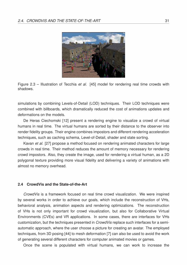
An important work by Tecchia et al. [45] describes a set of techniques for renderingcrowds in real time. Their approach is not only concerned with the human behaviors andcollision detection in crowds, but also in optimization techniques for fast rendering, whichinclude shadowing and quality shading. Using what they called “Pre Computed Impostors”as a Image-Based Rendering (IBR) technique and the availability of large texture memorybuffers, they maximized rendering speed. Figure 2.3 illustrates Tecchia’s et al. model forrendering real time crowds with shadows.
Hamill and O’Sullivan [19] resume a number of methods available for culling such asportal, occlusion horizons, occlusion shadow volumes and the simple bounding box tests.The vast types of environments, such as indoors and outdoors, used in the crowd simulationmakes common the use of multiple techniques combined. The Virtual Dublin [19] makeuse of culling and collision techniques combined with the trade of model details for texturedetails, reducing the building’s polygons, but increasing the memory required.
Another topic of research is concerned to improve better depth impression on impostors.An interesting billboard technique was developed by Decoret [14] in 2003, which he calledBillboard Cloud. His technique relies on combining a set of billboards in different layers tomake it almost indistinguishable when compared to 3D polygonal mesh.
The framework created by Pettre et al. [35] achieve the real time visualization of crowd
3Iterative Closest Point is a method to align free-form shapes, often used to reconstruct 3D surfaces.
2.4. CROWDVIS AND THE STATE-OF-THE-ART 31
Figure 2.3 – Illustration of Tecchia et al. [45] model for rendering real time crowds withshadows.
simulations by combining Levels-of-Detail (LOD) techniques. Their LOD techniques werecombined with billboards, which dramatically reduced the cost of animations updates anddeformations on the models.
De Heras Ciechomski [12] present a rendering engine to visualize a crowd of virtualhumans in real time. The virtual humans are sorted by their distance to the observer intorender fidelity groups. Their engine combines impostors and different rendering accelerationtechniques, such as caching schema, Level-of-Detail, shader and state sorting.
Kavan et al. [27] propose a method focused on rendering animated characters for largecrowds in real time. Their method reduces the amount of memory necessary for renderingcrowd impostors. Also, they create the image, used for rendering a virtual human, as a 2Dpolygonal texture providing more visual fidelity and delivering a variety of animations withalmost no memory overhead.
2.4 CrowdVis and the State-of-the-Art
CrowdVis is a framework focused on real time crowd visualization. We were inspiredby several works in order to achieve our goals, which include the reconstruction of VHs,behavioral analysis, animation aspects and rendering optimizations. The reconstructionof VHs is not only important for crowd visualization, but also for Collaborative VirtualEnvironments (CVEs) and VR applications. In some cases, there are interfaces for VHscustomization, but the techniques presented in CrowdVis replace such interfaces for a semi-automatic approach, where the user choose a picture for creating an avatar. The employedtechniques, from 3D posing [44] to mesh deformation [7] can also be used to avoid the workof generating several different characters for computer animated movies or games.
Once the scene is populated with virtual humans, we can work to increase the

32 CHAPTER 2. RELATED WORK
visualization believability, i.e how coherent the visualization is if compared with the reality.One way is through a behavior analysis of the virtual humans presented in the simulation.In Samovar and Porter’s words [38], “Language gives people a means of interacting withother members of their culture and a means of thinking. Language thus serves both asa mechanism for communication and as a guide to social reality”. In theaters there is aFrench expression called Mise-en-Scène and literally means “putting on stage”. It representsthe actors movements, positioning and background interactions during a theater play.Transposing this expression to virtual environments, such as those found on simulations andcomputer games, it symbolizes arranged interactions between background virtual humans.
As explained in the related work chapter, the interactions among VHs can representverbal or nonverbal communication, such as virtual humans checking their wristwatches,a simple “hello” gesture or even a conversation between two or more characters. InCrowdVis, the interactions are performed in “second plane”, without changing the simulationdata. The main difference in comparison with our approach is that we provide a modelto generate visual behaviors, which can be displayed as body animation or other anyvisual representation. But mainly, in our approach, the interaction behavior is generatedwithout changing the simulation, treated as a post-processing analysis, since it is used foralready simulated situations in our visualization. The main goal is to improve the realismand believability of the visualization (maintaining the simulation intact) and the techniquesemployed can also be used for other applications, such as games and any other suitablereal time scenario.
CrowdVis is also concerned with audio-visual inputs and feedback. It is important fora visualization framework being able to represent events that enriches both simulation andvisualization. For example, if we are visualizing a simulation concerned in analyzing theevacuation of a metro station after an explosion, it would be nice to represent the calmmoment and suddenly the bomb explosion with the sound of it, along with coherent motion ofthe virtual humans. These and other event situations [42] are common in crowd simulations.
Rendering real time crowds can be a challenge given the amount of geometry necessaryfor displaying. CrowdVis rendering techniques are based on Maciel [30], Tecchia [45] andPettre [35] works. We combine Level-Of-Detail techniques, including Progressive Mesh [23]for geometry simplification, and animated impostors. The main difference in our approachis being able to adjust the LOD distances according to the simulation and also the usageof a large set of textures. Moreover, we are able to provide realistic impostors because thenewer hardware increased their video memory capacity enabling great amount of texturesbeing handle, either by the Central Processing Unit (CPU) or the Graphics Processing Unit(GPU).

33
3. THE CROWDVIS MODEL
The main focus of this work is to provide a model for crowd visualization, that should actafter the performed crowd simulation. Visualizing such simulations require a set of data, e.g.virtual humans, terrains, virtual environments among others. Indeed, our model should dealwith the following aspects:
• creation of virtual humans;
• manipulation of scenarios and assets;
• manipulation of the simulation playback;
• control of virtual humans behaviors; and
• management of rendering features, special effects and scene illumination, presentedin Chapter 4.
An overview of CrowdVis is illustrated in Figure 3.1, where it is possible to observethe three main modules. The first module consists of a behavior analysis, responsible forparsing the simulation data, analyzing movement and animation patterns (human motions),detecting possible interactions between agents and manipulating screenplay animations(further explained in Section 3.1.3). The second module is concerned with reconstructionof virtual humans, where CrowdVis uses algorithms such as 3D pose identification, humansegmentation and silhouette processing, combined with template posing, mesh deformationand texturing techniques. At last, audio-visual features, exploring how to integrate specialeffects with the simulation in order to provide realism and believability among setting up thescene and rendering optimizations. This last part is presented in Chapter 4.
3.1 Behavior Analysis Module
The inputs of this module are two files: the simulation XML (see Listing 3.1) and thescreenplay XML (see Listing 3.3 in Section 3.1.3). The first input describes the motion of thevirtual humans and the second input contains specific animations that should be played foreach VH at a specific simulation frame. The motion of the agents is described by a set of 3Dpoints over a time sequence. In our model, all the simulations must follow this input format(exemplified in Listing 3.1), where each frame contains the positions for all the agents.

34 CHAPTER 3. THE CROWDVIS MODEL
Figure 3.1 – An overview of CrowdVis model. It is possible to observe the threemain modules (Behavior Analysis, Virtual Human Reconstruction, Audio-Visual) and theirrespective inputs.
1 <SIMULATION>2 <AGENTS>3 <AGENT i d =" 0 " ></AGENT>4 <AGENT i d =" 1 " ></AGENT>5 </AGENTS>6 <FRAMES>7 <FRAME> / / Frame [ 0 ]8 <AGENTS>9 <AGENT i d =" 0 ">
10 <POSITION>3.05 12.21 0.00 </POSITION> / / Pos i t i on o f Agent [ 0 ] a t Frame [ 0 ]11 </AGENT>12 <AGENT i d =" 1 ">13 <POSITION>37.41 12.21 0.00 </POSITION> / / Pos i t i on o f Agent [ 1 ] a t Frame [ 0 ]14 </AGENT>15 </AGENTS>16 </FRAME>17 <FRAME> / / Frame [ 1 ]18 <AGENTS>19 <AGENT i d =" 0 ">20 <POSITION>3.05 12.21 0.00 </POSITION> / / Pos i t i on o f Agent [ 0 ] a t Frame [ 1 ]21 </AGENT>22 <AGENT i d =" 1 ">23 <POSITION>37.41 12.21 0.00 </POSITION> / / Pos i t i on o f Agent [ 1 ] a t Frame [ 1 ]24 </AGENT>25 </AGENTS>26 </FRAME>27 <FRAMES>28 </SIMULATION>
Listing 3.1 – Simulation XML input data example for two distinct agents at two frames.

3.1. BEHAVIOR ANALYSIS MODULE 35
Considering the input files information, the Behavioral Analysis module has the goal toread the simulation data (set of 3D points over the time) and, after an analysis process,improve the results of crowd visualization. We detect and store possible human interactionsamong the VHs to be further visualized. These interactions are detected according to theagents distances and orientations, as detailed in next section. Another way to improve thevisualization results is by providing a realistic and believable motion of the VHs, for this,we use time coherence and an analysis of the agent’s velocity. At last, this module is alsoresponsible for coordinating predefined animations that the user may want to visualize duringthe playback, which we called screenplay animations. Next section details some of suchaspects.
3.1.1 Human Interactions
While studying and observing groups of humans, the anthropologist Edward Hall [18]proposed the proxemics concept, which describes that the distance between people, wheninteracting with each other, varies according to their levels of intimacy. Hall divided thedistances into four possible intervals: intimate [0.00, 0.45]m, personal (0.45, 1.20]m, social(1.20, 3.60]m and public (3.60, 7.60]m, as illustrated in Figure 3.2. Knowing these distancesbetween pairs of agents, we can play different types of animations in order to provide morebelievability to the whole scene, e.g. a gesture of hello or even to make a couple holdinghands according to the intimacy distance.
Figure 3.2 – Hall’s proxemics distances illustration of the four possible intervals: intimate[0.00, 0.45]m, personal (0.45, 1.20]m, social (1.20, 3.60]m and public (3.60, 7.60]m.

36 CHAPTER 3. THE CROWDVIS MODEL
Since our goal is to provide “visual behaviors” for interacting agents, we need to find outthe possible relationship between them in order to set a proper animation. Once we are notable to determine the affinity or even estimate the relatedness degree between the agents,we opted for using only Hall’s social and public proxemics. For these, we detect two commonsituations to perform real time interactions: i) agents walking together; ii) agents passing byeach other in opposite directions. In order to detect these interactions we use the proxemics,agent’s Field-Of-View (FOV), the duration of the interaction and the agent’s speed. Figure3.3 illustrates the two types of humans interactions detected in our model: agents walkingtogether (top) and agents passing by each other in opposite directions (bottom).
Figure 3.3 – Two types of VHs interactions detected in our model: the agents walkingtogether (top) and agents passing by each other in opposite directions (bottom).
In order to detect if agents are passing by each other in opposite directions, we firstlyverify the public proxemics according Hall’s public interval (3.60, 7.60]m (as illustrated inFigure 3.2). In our model, we opted for using a threshold of six meters from each one ofthe agents. In case a pair of agents are located in each other proxemics, we verify theirorientations and FOV to determine if they are going in opposite directions and if they areable to see each other, as illustrated in Equation 3.1:
γ = arccos(�v · �d), (3.1)

3.1. BEHAVIOR ANALYSIS MODULE 37
where �v is the agent’s orientation and �d is the vector between the two agents. If the visionangles calculated for both agents are inside our threshold1, we consider that the agents areseeing each other. The final step is responsible for checking how long this process lasts,in other words, when the agents do not see each other anymore. The process of verifyingthe event’s duration can also remove some visualization artifacts, i.e. when the interactionbetween the agents lasts shorter than the animation itself. Such situations can get worserwhen we have a higher density of agents interacting with each other.
The approach to detect if agents are walking together is a little bit different. In this case,instead of checking the agent’s FOV, we analyze the average velocity of each one of them.Since they are going into the same direction, they do not “see” each other using our FOVmethod. However, by analyzing the average velocity, we can tell if the agents are reallywalking together (side-by-side) or just passing by each other in the same direction. As theapproach previously explained, we also verify the proxemics, but for this particular case weopted for Hall’s social distance interval ((1.20, 3.60]m), using two meters as threshold, andthe difference of the average velocity must be inferior than 0.1m/s, value empirically definedbased in our tests.
In both approaches we check if the interaction events last longer than six seconds, wedecided this time interval based on the current animations length we provide. This is theminimal time, for a pair of agents, to have any sort of interaction. Figure 3.4 illustrates anagent passing by other while moving in the same direction, this case is ignored using theaverage speed metric and/or the interaction event duration metric.
Figure 3.4 – Illustration of an ignored case using our metrics, where an agent pass byanother while moving in the same direction.
1We adopted the common value of 120o for representing the human field-of-view [3].

38 CHAPTER 3. THE CROWDVIS MODEL
It is important to highlight that the human interactions do not change any aspect ofthe simulation. The animations performed by CrowdVis in the agents only provide visualbehaviors aiming to represent common real-life situations. All the animations are performedonly in the upper bones of the virtual humans. This approach allows the animation blendingwith regular animations, such as walk and idle.
3.1.2 Human Motion
The animations of embodied agents usually can be seen in three ways: predefined,real time computed animations or a combination of both. Predefined animations can becreated by artists using animation capable software and also by motion capture2. Realtime computed animations commonly are performed by using skeletal structures3. Insuch process, the bones are manipulated according to mathematical models creating theanimation. The combination of both techniques is what is often seen in novel 3D games. Inthis case, the VHs can interact with the scene while blending their predefined animation witha real time IK4 approach, mostly used for feet landing on top of the terrain or for graspingobjects.
CrowdVis approach for embodied agents animation relies on combining a set ofpredefined animations. Besides that, our model is responsible for playing and blending theanimations coherently. We divided into four possible animations, which we called regularanimations: idle, slow walk, normal walk and jog. Our approach is based on analyzing theagent’s displacement in order to provide a visually accepted realistic motion for the VHs,which can be seen during the visualization. Figure 3.5 illustrates the regular animations ofthe three movement cases: slow walk, normal walk and jog, using a male virtual human.
Figure 3.5 – Illustration of the regular animations of the three movement cases: slow walk,normal walk and jog, using a male virtual human.
2Process of recording the movement of real persons.3Structure often used to animate VHs, allowing to manipulate the geometry using the skeleton bones.4Equations to determine the joint parameters providing a desired position at the end-effector.

3.1. BEHAVIOR ANALYSIS MODULE 39
In order to provide a visually accepted realistic motion, firstly we need three averagevelocities for the VHs that match their slow walking, normal walking and jogging animations.The average velocities of a VH relies on a set of factors, such as the height of the human,the animation itself (e.g. jogging or walking), age, weight, among others. For determiningfor each movement case the expected average velocity, we simply obtained the distancetraveled5 after one second for that VH. These velocities information are stored in the virtualhumans’s configuration file, as described in Listing 3.2.
1 scale =0.022 / / V i r t u a l human scale23 slowwalkspeed =0.58 / / Slow walk animat ion speed r a t i o i n one second4 walkspeed =1.80 / / Normal walk animat ion speed r a t i o i n one second5 jogspeed =1.97 / / Jog animat ion speed r a t i o i n one second67 ske le ton=man5−ske le ton .CSF / / Cal3d ske le ton f i l e name89 animationname= i d l e / / I d l e animat ion name to be used i n s i d e CrowdVis
10 animat ion=man5−i d l e .CAF / / I d l e animat ion f i l e name1112 animationname=walk / / Walk animat ion name to be used i n s i d e CrowdVis13 animat ion=man5−walk .CAF / / Walk animat ion f i l e name14 animationname=walkslow / / Slow Walk animat ion name to be used i n s i d e CrowdVis15 animat ion=man5−walkslow .CAF / / Slow Walk animat ion f i l e name16 animationname=run / / Jog animat ion name to be used i n s i d e CrowdVis17 animat ion=man5−run .CAF / / Jog animat ion f i l e name1819 animationname=humaninteract ionA / / De fau l t passing by human i n t e r a c t i o n animat ion name to be used by CrowdVis20 animat ion=man5−wave .CAF / / Human i n t e r a c t i o n A animat ion f i l e name21 animationname=humaninteract ionB / / De fau l t walk ing toge ther human i n t e r a c t i o n animat ion name to be used by CrowdVis22 animat ion=man5−ges tu r ing .CAF / / Human i n t e r a c t i o n B animat ion f i l e name2324 mesh=man5−mesh . cmf / / V i r t u a l human mesh f i l e name2526 ma te r i a l =man5−mate r i a l .CRF / / V i r t u a l human ma te r i a l f i l e name
Listing 3.2 – Virtual human’s configuration file example illustrating the average velocitiespreviously calculated.
Once we have the average velocities for each movement case, we discover the distancetraveled by the agent at each second of the simulation. By analyzing if the agent’sdisplacement is smaller than 0.1m, the model is responsible for blending the currentanimation to one of the available idle animations. On the other hand, if it is greater or equalthan 0.1m, then one of the three movement animations could be played (slow walk, normalwalk or jog). Fruin [15] described intervals for average adult walking velocities. Theseintervals are used to decide which animation shall be played, as listed bellow:
• idle animation [0.0, 0.1)m/s;
• slow walk animation [0.1, 0.6)m/s;
• normal walk animation [0.6, 1.4)m/s; and
• jog animation [1.4,+∞)m/s.
5Distance obtained while the VH is moving in a straight line.

40 CHAPTER 3. THE CROWDVIS MODEL
By comparing the calculated distance in the simulation with the average velocity storedin the VH’s configuration file, we can change the movement animations speed in order to beplayed slower or faster, making the VH motion more believable and synchronized, preventingthat the VHs “slide” on the floor, artifact usually noticed when the translation is faster thanthe VH walking animation. In order to obtain, for each agent i, the animation speed factorsi, we measure the distance traveled dti after one second of simulation, and then divide itby the current average velocity avi previously estimated for that movement case (informationstored in the VH’s configuration file), as illustrated in Equation 3.2:
si = dtiavi. (3.2)
In CrowdVis, the only information required in the simulation XML are the positions ofthe agents recorded during the simulation, separated by frames. The small amount ofinformation required facilitates the output creation for the crowd simulators. On the otherhand, we are not able to take advantage of other information that could be provided bythe simulator, such as the agent’s orientation. The next step in this module is to use thesimulation information regarding the agent’s position for calculating where the agent shouldbe facing (oriented) at the end of each frame. Figure 3.6 illustrates the virtual humans’sorientation path for one second of simulation.
Figure 3.6 – Example of a VH’s orientation path for one second of simulation.
For orienting our embodied agents during the visualization, one can calculate adirectional vector between the positions regarding the current frame and the next one. Thisapproach creates several visualization artifacts, given that usually the models create theagents motion as points and not bipeds. As previously explained, a set of 3D positionsrepresent exactly one second of simulation (usually one second is represented by 30 3Dpositions, but it may vary according the input simulation). For this reason, the slower

3.1. BEHAVIOR ANALYSIS MODULE 41
an agent translates, more positions are plotted for that same agent in the same distanceinterval. Figure 3.7 illustrates the 3D points provided by a simulation model for a straightpath, where the black dots represent the 3D positions and the red lines an illustration of thestraight path, desired in the simulation.
Figure 3.7 – Illustration of the 3D points provided by a simulation model for a straight path,where the black dots represent the 3D positions and the red lines an illustration of the straightpath, desired in the simulation.
In order to achieve a better orientation for the agents, we use time coherence in ourcalculations. As the velocity calculation analyzes the next second of the simulation, we alsocalculate the resultant vector that indicates the destination that each agent desires to faceafter one second. We use this data to calculate the orientation �O(t) for the next frame, wheret means the time in frames, p(t) is the current position and p(t + 1) is the next position. Inour prototype we use the value 30 for N , executing at a rate of 30 frames per second. Itis important to mention that, during the sum, the distances between this and the next stepmust be smaller than 2.5 meters, otherwise it is not taken into account. This approachavoids incoherent behaviors given sudden changes of direction of an agent, as illustrated byEquation 3.3:
�O(t) =
⎧⎪⎨⎪⎩t = 0, 0
t > 0, ( �O(t−1))+(∑t+Ntp(t+1)−p(t))
2 .(3.3)

42 CHAPTER 3. THE CROWDVIS MODEL
3.1.3 Screenplay Animation
Even if CrowdVis is in charge of determining a set of regular animations to be playedautomatically, the user must be able to play their own specific animations, which we calledscreenplay animations. These animations can be played at any time during the simulation,for example: Agent [39] Play [Jump] at Frame [348]. To possibilitate users to do this, a XMLscript (see Listing 3.3) can be loaded containing the following information: agent id, name ofthe animation and a start frame. Figure 3.8 illustrates the virtual human playing a sit downanimation at a specific simulation frame.
Figure 3.8 – Illustration of a screenplay animation provided by the user, where a virtualhuman starts playing in loop a custom animation at a specific simulation frame.
When a screenplay animation is loaded, it is played repeatedly in loop. In case the userdoes not desire to be in control of the agent’s animation anymore, simply need to providethe animation name as clear in the desired frame in order to turn it off (also illustrated inListing 3.3).
1 <SCENE>2 <ACTONS>3 <ACTON>4 <AID>0</AID> / / Agent ’ s ID5 <NAM>sitdown </NAM> / / Animation name to be played6 <FRA>100</FRA> / / S t a r t frame f o r the animat ion to be played7 </ACTON>8 <ACTON>9 <AID>0</AID> / / Agent ’ s ID ( the same as before )
10 <NAM>clear </NAM> / / Clear word f o r re l eas ing animat ion c o n t r o l11 <FRA>200</FRA> / / Frame i t should be released back to CrowdVis12 </ACTON>13 </ACTONS>14 </SCENE>
Listing 3.3 – Screenplay XML input data example where we can observe the word clear forreleasing the animation control back to the CrowdVis.

3.2. VIRTUAL HUMANS RECONSTRUCTION MODULE 43
CrowdVis must not interfere in screenplay animations, in other words, regular animationsand human interactions animations are only calculated in case there are no screenplayanimations being executed for the current agent. The following pseudo-algorithm illustratedin Listing 3.4 indicate the priorities between the possible type of animations to be played bythe VHs.
1 IF ( screenplay )2 play screenplay animat ion ;3 ELSE IF (NOT screenplay AND i n t e r a c t i o n )4 p lay human i n t e r a c t i o n animat ion blended wi th i d e n t i f i e d regu la r animat ion ;5 ELSE6 play i d e n t i f i e d regu la r animat ion .
Listing 3.4 – Pseudo-algorithm indicating the priorities between the possible type ofanimations to be played by the VHs.
A particular case in our approach can occur when the user loads a screenplay animationfor a virtual human which is currently involved in an human interaction. When thishappens, as explained before, our model prioritizes the screenplay animation over thehuman interaction animations. In this particular scenario, one agent can interact alone. It isimportant to reiterate that all the processed and stored interaction behaviors can be turnedoff at any moment during the visualization, using CrowdVis prototype’s interface. AppendixA contains a flowchart for more technical detailed information about the Behavior Analysismodule.
3.2 Virtual Humans Reconstruction Module
To create a virtual human, a set of basic steps must be satisfied such as: modeling,rigging6, texturing and animating. These steps can take a large amount of time from theartist, situation worsened when the artist needs to create several different virtual humans.For this particular reason we provide in CrowdVis a set of VHs that we created and also amodule for semi-automatic reconstruction of VHs [7].
The reconstruction approach is semi-automatic, since the user must provide a few clickslocating the joints of the human structure. There are six steps7 in order to achieve ourreconstruction goals: 3D Pose Identification, Human Segmentation, Silhouette Processing,Template Posing, Mesh Deformation and Texturing.
Step 3.2.1 is responsible for generating a bone structure based on Taylor work [44],including biomechanical restrictions, and recording the result data in a XML file. Thistechnique works with an user input (2D clicks at the joints of the human of the picture).Step 3.2.2 consists in image processing. The goal at this point is to segment and extractthe human in the picture. Step 3.2.3 finds out the body parts width and record it on the
6Usually rigging is the name given to the process of preparing the mesh and bones for animating.7Steps 3.2.1, 3.2.2 and 3.2.3 represent models developed by other people in research group and are briefly
explained.

44 CHAPTER 3. THE CROWDVIS MODEL
same XML file generated by the first module. Steps 3.2.4, 3.2.5 and 3.2.6 are responsiblefor manipulating all obtained data and generate a fully animated and textured virtual human,using algorithms for reconstructing (mesh deformation) and texturing.
3.2.1 3D Pose Identification
In this first step, the user must click to indicate where in the picture is the human bodymajor joints (see Figure 3.9 left). This data is handled by Taylor algorithm [44], whichanalyzes every joint location based on human body skeletal dimensions and then determinesthe estimated depth of each bone. In other words, Taylor’s algorithm retrieves the 3D worldcoordinates of each joint.
This approach generates uncomfortable or even impossible poses for human beings,such as broken arms or twisted legs, due to the ambiguity resulted when applying Taylor’stechnique. In order to discard these incoherent poses, an approach was proposed inorder to check the possible angles between the joints based on the human’s biomechanicalknowledge [5]. The body biomechanical constraints consider the relationship of bones linkedthrough joints and also the joints Degrees-Of-Freedom (DOF). The results of this step arestored in a data file (Skeleton Data) containing each joint position representing the postureaccording to the picture used as input. Further details of this work can be found at [7].
3.2.2 Human Segmentation
The automatic segmentation of human subjects is still a challenge, mainly due tothe influence of numerous real-world factors such as shading, image noise, occlusions,background clutter and the inherent loss of depth information when a scene is capturedinto a 2D image [24].
The bone structure data, previously clicked by the user, provides information of each bodypart location, allowing the color model to stipulate a color region for each one of those. Theregions are based on human anthropometry [47] creating a structure we called BoundingBones8, that covers approximately the human body area (see Figure 3.9 center). This regionis used for learning and searching the dominant colors that represents the human in thepicture. Figure 3.9 shows the initial pipeline of the virtual humans reconstruction where isillustrated the 2D bone clicking process (left), the bounding bones (center) which are theregions used by our color model algorithm and the binary image representing the extractedhuman segmentation (right).
At the end of this step, for each body part, regions of the picture are selected to beused as texture (see Step 3.2.6). In some pictures the face employed in the template meshmay be not accurate, due to the head orientation (works only with frontal poses). If the
8Our adopted concept of bounding box representing each bone.

3.2. VIRTUAL HUMANS RECONSTRUCTION MODULE 45
Figure 3.9 – The initial pipeline of VHs reconstruction, where is illustrated the 2D boneclicking process (left), the bounding bones (center), which are the regions used by ourcolor model algorithm, and the binary image representing the extracted human segmentation(right).
result is not visually acceptable, the user can try another picture or manually provide a facetexture. Figure 3.10 illustrates the human and the automatic texture chunks obtained forfuture texturing.
Figure 3.10 – Illustration of the the automatic texture chunks obtained for future texturing.
3.2.3 Silhouette Processing
Given the binary silhouette of the person and the 2D clicked joints data, we estimate thewidth of each body part. The main idea is to compute the length of line segments connectinga bone and the boundary of the silhouette, robustly estimating the corresponding width.
We retrieve the bones by connecting the joints. For each bone is traced a perpendicularset of line segments. Each line segment ends following two rules: i) the next pixel is ofwhite color (end of the human body part). ii) the line segment has 35% of the bone length(value estimated given human limbs average width [47]). After collecting all data, the median

46 CHAPTER 3. THE CROWDVIS MODEL
for each body part is recorded in a data file (Body Width). Figure 3.11 shows the binarysilhouette (left) and the estimated widths for each body part (right), where the green line isthe median width.
Figure 3.11 – Binary silhouette (left) and the body parts width estimation for automaticreconstruction (right), where the green line is the median width.
3.2.4 Template Posing
This and the next steps are responsible for employing the previously obtained data inorder to make the human template mesh to look like the human in the picture. CrowdVisprototype contains only a few buttons and panels in order to enable the user to load a JPGpicture file. All the other data is automatically loaded. Figure 3.12 illustrates CrowdVis VHreconstruction interface.
Figure 3.12 – Illustration of CrowdVis VH reconstruction interface.

3.2. VIRTUAL HUMANS RECONSTRUCTION MODULE 47
In this model, we are not able to decide the gender of the human by just processing thepicture, so the user needs to previously decide if the template model will be male of female,each one containing 4825 and 4872 vertexes, respectively. Figure 3.13 illustrates the male(left) and female (right) template models in their initial state (T-like posture, without any meshdeformation and texture information).
Figure 3.13 – Illustration of the male (left) and female (right) template models in their initialstate (T-like posture, without any mesh deformation and texture information).
The VH template initially adopts a standard T-like posture, as illustrated in Figure 3.13.We represent each bone i of the virtual human vh by a vector bivh given by the differenceof its final joint position and its initial joint position, observing the skeleton hierarchy. Itscorrespondent bone from the real human of the picture p (recorded in the Skeleton Datafile explained in Step 3.2.1) is represented by the vector bip . We can find out the angleΘi between these vectors by computing the arccosine of their dot product. After that, itis possible to determine the quaternion qi in order to rotate bivh to achieve the desiredorientation (i.e. the orientation of bip , where �ni is computed by the cross product betweenbivh and bip as shown in Equation 3.4:
qi = (cos(12Θi), sin(
12Θi)�ni). (3.4)
Our approach can also generate angle ambiguity for rotations, this is fixed by comparingthe joints 3D position with the ones provided in the Skeleton Data file. Each quaternion,describing the rotation of every joint of the VH template, is multiplied by the correspondentquaternion stored in the skeleton. In other words, we can determine the quaternion qi inorder to rotate bivh to the desired orientation (i.e. the orientation of bip), according to Equation3.5:
b′ivh = qi bivh q−1i . (3.5)

48 CHAPTER 3. THE CROWDVIS MODEL
3.2.5 Mesh Deformation
After rotating the bones of the VH template to match the 3D pose identified in the picturewe deform the mesh of the VH template using the Body Width data obtained in Step 3.2.3.Given the width of each body part wi and the length of the bone li recorded in the XMLfiles (described in steps 3.2.3 and 3.2.1) from the real human in the picture, we compute foreach body part i in the picture p, the ratio rip = wip
lip. The correspondent ratio rivh = wivh
livh
is computed for the virtual human vh in its original form. Using these ratios, we compute avertex displacement factor fi according to the Equation 3.6:
fi = rip − rivh . (3.6)
Then, for each vertex of the virtual human, we apply such displacement factor inthe direction of the normal vector �nv. Equation 3.7 calculates the vertex new positionv′ = (x′v, y′v, z′v) related to its original position v = (xv, yv, zv):
v′ = v + f |livh| �nv. (3.7)
In some cases, given a problem during the segmentation process of the picture and/orthe silhouette processing, the width factor of some computed body parts can be too bigor too small than expected, as illustrated in the right thigh of Figure 3.11 (right). In orderto avoid incoherent deformations there are two rules in this step: i) case the calf factor isgreater than the thigh factor, then the thigh uses the calf factor. ii) case the forearm factor isgreater than the arm factor, then the arm uses the forearm factor.
Since the virtual human is divided in a set of body parts, after displacing all the vertex totheir correspondent deformed positions, the VH’s mesh needs to be “stitched” at each bodypart intersection in order to prevent visualization artifacts, as illustrated in the examples(a), (b) and (c) in Figure 3.14. For stitching up the vertexes we created a based on theoriginal template mesh associating the boundary vertexes closer than one centimeter, valueempirically obtained given the template mesh geometry topology.
(a) (b) (c)
Figure 3.14 – (a), (b) and (c) are illustrations of reconstructed virtual humans without beingstitched after the vertex displacement process.

3.2. VIRTUAL HUMANS RECONSTRUCTION MODULE 49
3.2.6 Texturing
Texturing is definitely an important task to be done, not only in order to increase thesimilarity between the virtual human and the real human in the picture, but also for the VH tobe used in a realistic crowd visualization. Figure 3.15 illustrates the template model without(left) and with (right) texture, where the color information increase the realism of the VH.
Figure 3.15 – Illustration of the template model without (left) and with (right) texture, wherethe color information increases the realism of the VH.
The challenge in texturing the reconstructed virtual humans is due to the fact that a single2D picture does not provide the information of occluded body parts. In other words, this lackof information does not allow to fully paint a 3D model with the correct color information(such as the VH template back part). The approach used in this work aims to ensure thatthe frontal part of the VH is similar to the human in the picture, since we have the VH in thesame posture than the picture. The idea is to simply remap the texture coordinates for thehead, chest and belly body parts, creating a planar technique to plot the previously obtainedtextures. Figure 3.16 illustrates the difference between default UV mapping (left) and theplanar mapping (right) techniques.
Figure 3.16 – Illustration comparing the default UV mapping (left) and the planar mapping(right) techniques.

50 CHAPTER 3. THE CROWDVIS MODEL
In order to execute what we called planar mapping technique for the body parts describedabove, we first search for the six extreme vertexes (left/right most, top/bottom most andnear/far most). After this process, we can retrieve the frontal visible part (group of vertexes)for each one of the three body parts. For each group of vertexes we remap each vertex’stexture coordinate and calculate the vertex new texture coordinate for X axis vtx′ and Y axisvty′, where rx and lx represents the right most and left most extreme vertex of the X axis,respectively, as shown in Equations 3.8 (X axis) and 3.9 (Y axis):
vtx′ = x− rx‖rx − lx‖ , (3.8)
vty′ = 1−(
y− ty‖ty − by‖
). (3.9)
The CrowdVis prototype (presented in next chapter) is able to export the reconstructedcharacters to OBJ9 format files. Once the VHs are exported, artists are able to fix textureartifacts created during the reconstruction, adjust the mesh topology or even use the VHsfor other purposes, such as in a game. The drawback is the loss of the default animationspresented in the reconstructed VHs, since this information is not supported by OBJ files.
Although the reconstruction may not be highly accurate, the whole creation process isfast, and it provides good visual results that maintain coherence with the original picture. TheCrowdVis VHs are all Cal3D10 format, which means that users can load any character of theirown, created with any tool, if they are in the proper format. User’s customized charactersmust follow the format of the agent configuration file (see Listing 3.2). Figure 3.17 illustratesthe pipeline of VHs reconstruction.
(a) (b) (c) (d)
Figure 3.17 – Illustration of the VH reconstruction pipeline, where (a) is the estimated 3Dpose detected, (b) is the segmentation and texture chunks attainment process, (c) illustratesthe silhouette processing and (d) is the result of mesh deformation and texturing techniques.
9File format developed by Wavefront Technologies containing geometry information.10http://gna.org/projects/cal3d/

51
4. THE CROWDVIS PROTOTYPE
As mentioned before, CrowdVis uses an approach which detaches the visualization fromsimulation aspects. In this case, the advantage is the possibility of using different crowdsimulators and only be concerned with the visualization itself. This chapter aims to presentthe CrowdVis prototype’s audio and visual features, which include rendering optimizationstechniques and the available special effects, that can be used for enriching the visualization.
4.1 Audio-Visual Module
Once we have the simulation data and the virtual humans, we can work to provide agood visualization in real time frame rates1, that also includes setting up the environment,configuring the virtual humans visualization along with LOD techniques, lighting control andalso a set of special effects in order to include sound, shadows, stereoscopic and particlerendering.
4.1.1 Environment
When simulating crowds for evacuations, emergency situations or any other purposes,it is important to be able to visualize the script which the simulation is running on. Forexample, either simulating the end of a soccer match or people running to get aboardlifeboats, visualizing the halls, doors and obstacles helps comprehension of the situatedenvironment being simulated. For this reason, the framework provides tools for loadingand manipulating 3D assets. Since CrowdVis uses Irrlicht Engine2 for the fixed pipelinerendering, a set of assets formats can be used, which include: B3D (.b3d), Microsoft DirectX(.x), Quake (.md2, .md3 and .bsp), 3D Studio (.3ds), Alias Wavefront Maya (.obj), amongothers.
Some of the crowd simulations also aim to evaluate the motion of the virtual humans inrealistic environments. To represent these scenarios, such as terrains, can be a difficult andcomplex task, since natural scenarios are composed by forms with a lot of details that shouldbe reproduced realistically in the virtual world [8]. The 3D terrains can be represented by adata structure called heightmaps, which stores the height values of the terrain using a matrixof points [29].
The heightmaps matrices can be stored as textures, in image files such as BMP or PNG,as illustrated in Figure 4.1 (a), where the brighter parts represent the higher parts of theterrain. We enable the users to visualize terrain-driven simulations, for this, the users can
1We consider to be real time when the frame rate executes at 30 frames per second or more.2http://irrlicht.sourceforge.net/

52 CHAPTER 4. THE CROWDVIS PROTOTYPE
load a heightmap image (smaller than 256x256 due to the implementation optimizations),and the users can also customize a few terrain properties: terrain’s texture, size, orientationand position (see Figure 4.1 (b)).
(a) (b)
Figure 4.1 – Illustration of a heightmap image (a), where the brighter parts represent thehigher parts of the terrain. The users can also customize a few terrain properties: terrain’stexture, size, orientation and position (b).
In CrowdVis, any loaded asset to be used as part of the scene is marked as static inthe GPU caching, which means that the vertexes and indexes rarely will be changed, forthis reason, dynamic meshes are not supported. On the other hand, this approach enablesa faster rendering time for the visualization. There are two possible ways of loading thescenario: i) manually choosing the mesh files (one at a time) and positioning them in thescene. ii) Using a script (scene XML file) which contains the name of the mesh file, positionin the virtual world, its orientation (0o to 360o) and its scale (three values, one for eachdimension), as described in Listing 4.1.
1 <SCENE>2 <OBJCTS>3 <OBJCT>4 <NAM> t ree .3 ds </NAM> / / Name of the ob jec t to be loaded5 <POS>5 0 0 </POS> / / Pos i t i on o f the ob jec t (X,Y, Z )6 <ROT>0 90 0 </ROT> / / Rota t ion o f the ob jec t (X,Y, Z )7 <SCA>0.8 1 0.8 </SCA> / / Scale o f the ob jec t (X,Y, Z )8 </OBJCT>9 <OBJCT>
10 <NAM>bench . obj </NAM>11 <POS>7 0 −2</POS>12 <ROT>0 0 0 </ROT>13 <SCA>1.5 1 1 </SCA>14 </OBJCT>15 </OBJCTS>16 </SCENE>
Listing 4.1 – Scene XML input data example for two objects.
Besides being able of positioning, rotating and scaling the scene assets, the user canalso change a few object’s properties: wireframe rendering, transparent material, enable

4.1. AUDIO-VISUAL MODULE 53
or disable cullface and enable or disable if object receives lighting. Figure 4.2 illustratesthe manipulation of scene assets and the interface, indicating the tools presented formanipulating objects and light source positions, orientations, among others.
Figure 4.2 – Illustration of the manipulation of scene assets and the interface, indicatingthe tools presented for manipulating objects and light source positions, orientations, amongothers.
It is also important to navigate into the scenario easily. We provide three types of cameracontrol:
• First Person Camera - control the camera using the Arrows/WASD keys and mouse;
• 3rd Person Camera - by clicking over a virtual human the camera follows the agentenabling the scroll wheel for zooming and right and middle mouse buttons for heightadjust; and
• Script Camera - flies through a set of 3D points in the scene using our prototype’sinterface.

54 CHAPTER 4. THE CROWDVIS PROTOTYPE
4.1.2 Virtual Humans
The virtual humans are for sure the most important part of our visualization, withoutthem we would have only points or cylinders moving around the scene, what is usuallyhow the humans are represented in crowd simulators. As explained in Section 3.1, ourvirtual humans are capable of self adjusting their animation speed, detecting possible humaninteractions among them and playing screenplay animations provided by the user. In orderto do that and achieve real time frame rates we worked on a few optimization techniques,such as Level-Of-Detail, animated impostors and normal maps.
Levels-Of-Detail [11] can be explained as different representations of the same objectthat can be used in a way to improve performance. The common approach in games andother real time applications is to use LOD bounded to the geometry of the object, wherethese objects possess several layers of mesh simplifications, the simpler is the geometrythe lesser is the memory consumption and higher is the computation speed of vertexestransformations in the GPU.
Progressive Mesh is a mesh simplification technique developed by Hughes Hoppe [23]in 1996. The author presents a mesh simplification procedure which the main idea is topreserve the geometry of the original mesh and its overall appearance making the usageof material identifiers, color values, normals, and texture coordinates. Using this technique,besides simplifying our VHs meshes, we can also maintain their appearance making barelyunnoticeable the geometry popping3 when navigating with the camera through the scene.Figure 4.3 illustrates the three Levels-Of-Detail, low quality (left) medium quality (center) andhigh quality (right), with the respective numbers of triangles and polygons.
Figure 4.3 – Illustration of the three Levels-Of-Detail, low quality (left) medium quality(center) and high quality (right), with the respective number of triangle and polygons.
3In computer graphics the abrupt geometry changes for different Levels-Of-Details are known as popping.

4.1. AUDIO-VISUAL MODULE 55
Rendering geometries with low amount of polygons is definitely faster for the GPU, butthe visual quality of these meshes comes up worse than the expected. In 1978, James Blinn[6] created the concept of bump mapping. In a few words, the idea is to replace the vertexesnormals by a heightmap texture in order to calculate the lighting for the 3D object. Further,this technique was improved using normal map [28] textures, where each pixel (using RGBchannels) represents a normal vector for lighting calculations. Both approaches are veryhandy for visualizing simple geometry meshes with better details. Figure 4.4 illustrates oneof our virtual humans using normal map technique (left) and using regular lighting technique(right).
Figure 4.4 – Illustration of a virtual human using normal map technique (left) and usingregular lighting technique (right).
There are other techniques to reduce the amount of polygons presented in the embodiedagents than just simplifying the 3D geometry [25]. The common approach is to create asingle image of the agent, drastically reducing the geometry necessary for representing thevirtual human, on the other hand, a lot of information is lost, such as lighting, animation anddepth information. Image-Based Rendering has received a large set of research results [45],in CrowdVis we use these techniques for rendering animated impostors, which is how theVHs are represented when they are far away from the camera.
For incorporating animations in impostors, two approaches are commonly used: i)previously store the animation frames as textures and play it during simulation. ii) renderthe textures dynamically in real time [40] for each character. Both approaches consumememory and GPU, besides that, rendering textures in real time for a large number or agentscan be computational expensive, leading to the necessity of other rendering techniques. InCrowdVis we opted for the first approach, using a previously created set of textures for theimpostors.
Usually in crowd impostors techniques, there is a trade-off between memory and visualquality. The amount of necessary video memory can be significantly larger if the agents arerepresented by more images (e.g. the usage of an extra set of images for animation).

56 CHAPTER 4. THE CROWDVIS PROTOTYPE
CrowdVis combines an animated impostors technique with the agent’s geometry LOD,which means that distant agents in our visualization are replaced by view-dependentimpostors, same approach presented by Maciel [30]. Each impostor contains a set of 3072textures, each one with 128x128 resolution. These textures are previously processed andare stored in the Hard Disk Drive (HDD). Figure 4.5 illustrates part of our set of impostorstexture for a single agent.
Figure 4.5 – Illustration of four textures (front, right, back, left) of the 3072 impostor textureset. All the textures are previously generated and stored in the hard disk drive, each onewith the resolution of 128x128 pixels.
According to the camera point-of-view, the direction that the agent is facing (agent’sorientation) and the current animation frame, it is possible to determine which one of the3072 textures should be used as impostor for that frame. This algorithm is only executedfor those agents which are at a specific distance from the camera, saving CPU resources.Equations 4.1 and 4.2 present the approach for determining the best texture (according tothe agent’s orientation in relation to the camera point-of-view) using the spherical coordinatesystem for 64 angle intervals, where az is the azimuth, lat is the latitude, θ is the anglecomputed in the horizontal plane, ϕ is the angle computed in the vertical plane, K is theconstant that represents the number of slices (CrowdVis uses 4 as K value) and r is thesquared distance between the agent and the camera. The computed values are within thefollowing domain: 0 ≤ r <∞, 0 ≤ θ < 2π and 0 ≤ ϕ < π. Follow the equations:
az =⌊
4θπ
⌋, (4.1)
lat =
⎧⎪⎨⎪⎩θ < π,
⌊Kϕπ
⌋θ ≥ π,
⌊K(ϕ+π)π
⌋.
(4.2)
Once we obtain the computed angles we can now change the animated impostor maintexture to the best suitable one, as illustrated in Figure 4.6. CrowVis provides two animationsfor the impostors: idle and walk. Each animation has a set of 24 textures and are represented

4.1. AUDIO-VISUAL MODULE 57
by 64 different camera angles around the virtual human (eight azimuth slices and anothereight slices for latitude). We opted for using two animations due to the memory requiredfor loading all the texture set. Besides that, the user can also choose the frame frequencyof the impostor’s animation (1Hz to 24Hz), according to the user’s computational powerrequired for rendering. Table 4.1 presents the amount of video memory used and Frames PerSecond (FPS) when loading a scene with nine different VHs instances, using only animatedimpostors at a 24Hz animation frequency.
Table 4.1 – Comparison between the number of agents illustrating the amount of videomemory used and the frame rate (in seconds) for nine different VHs instances, using onlyanimated impostors at a 24Hz animation frequency.
Number of Agents Video Memory (MB) FPS100 1.269 195210 1.279 1404200 1.625 16
Figure 4.6 – Illustration of CrowVis approach for determining the best suitable animatedimpostor texture according to the agent’s orientation and the camera point-of-view. On theright we can see the sphere illustrating the 64 slices for the different available perspectives.
Table 4.2 presents the distances, the number of polygons and the LOD being utilizedin our views for only one of our virtual humans in the scene, the distances were decidedbased on quantitative and qualitative tests. These tests considered the FPS in a crowdedenvironment and the geometry popping artifact for the agents. The LOD distances can beadjusted by the user at any moment of the visualization.
Once a VH is loaded into CrowdVis, we create a static structure for storing them. Thisapproach is faster than loading dynamically the geometry for each animation frame. On theother hand, it complicates the usage of a continuous LOD. Figure 4.7 illustrates the exactsame scene and camera view for 100 agents without (left) and with (right) LODs.

58 CHAPTER 4. THE CROWDVIS PROTOTYPE
Table 4.2 – Comparison for evaluating the FPS using the distances, the number of polygonsand the LOD utilized for one virtual human in the scene. These LOD distances can beadjusted using CrowdVis prototype’s interface according to the user need.
Camera Distance Level-of-Detail Number of Polygons Frames Per Second[0:4] meters High Detail 2856 722[5:9] meters Medium Detail 1254 782
[10:25] meters Low Detail 954 798[25:above] meters Impostor 2 900
Figure 4.7 – Illustration of the exact same scene and camera view for 100 agents in twodifferent renderings: without LOD technique (left) and with LODs technique and impostors(right).
For large scale simulations the user can represent the agents as animated impostorsonly. This approach is faster with good visual results, but the drawback are the loss ofmultiple animations and the human interaction events. Figure 4.8 illustrates CrowdVisprototype rendering 5000 animated impostors for a large scale simulation.
Figure 4.8 – Illustration of 5000 animated impostors for large scale simulations. Thedrawback of this approach is the loss of multiple animations and the human interactionevents.

4.1. AUDIO-VISUAL MODULE 59
We also provide the possibility of loading environmental agents. These virtual humansare not part of the simulation and can be loaded only with the purpose of enriching the scenevisualization. For loading them the user just fill a set of parameters located in CrowdVisprototype’s interface corresponding to the agent’s position, scale, rotation and animation(played in loop during the entire visualization).
4.1.3 Special Effects
This part is responsible for several tasks in order to improve the framework visual qualityand to enrich the visualization. At each new day the hardware industry enables bettergraphics, and the latest engines provide several techniques to create such graphics, usuallythese techniques can execute during the frame loop rendering or even as post processrendering shader. In order to achieve good graphical results and enable the user somefeatures for visualization, we included a few set of techniques related to real time rendering,usually employed in games.
The usage of shadows helps to improve the overall realism of the scene and also providesvisual cues that assist the perception that anchors the agents to the ground [45]. In order toprovide more realism during visualizations, CrowdVis proposes two shadowing techniquesfor the VHs.
The user may choose one of them or neither (removing the shadows optimize thevisualization performance). The simpler and cheaper computational technique is largelyused in old video game titles, it consists in loading a plane with a “circular” texture beneaththe objects. Figure 4.9 illustrates two types of shadowing technique present in Tomb Raider 4
game series: the simple circular shadow plane (left) and a stencil buffer technique (right).These shadow textures have 128x128 of pixel resolution, besides that, each texture isadapted to the scale of the VH.
Figure 4.9 – Illustration of two types of shadowing technique present in Tomb Raider 4 gameseries: the simple circular shadow plane (left) and a stencil buffer technique (right).
4http://www.tombraider.com - Tomb Raider series is published by Eidos Interactive.

60 CHAPTER 4. THE CROWDVIS PROTOTYPE
The other shadowing technique present in CrowdVis improves the visual resultsconsiderably, but it is more computational expensive. This shadowing approach is basedon shadow maps technique. Shadow maps concept was created in 1978 by Lance Williams[50] and the main idea is to use a light source projection and a target, in order to create theshadows from that perspective. We offer three possibilities: i) attach the light source to thecamera, ii) attach the light source to one of the scene lights. iii) attach the light source toone of the VHs, above the head. Figure 4.10 illustrates both shadowing techniques presentin CrowdVis for visual comparison.
Figure 4.10 – Illustration of both shadows techniques present in CrowdVis: simpleshadowing (left) and complex shadowing (right).
CrowdVis complex shadowing technique uses a 1024x1024 texture, and it isimplemented in the GPU for real time results. Even though, it severely decreasesperformance, so we recommend to only use this approach when visualizing a small setof VHs. Table 4.3 shows the number of agents and FPS when shadow technique is enabledand disabled. When the agents are rendered as animated impostors they can only use thesimple shadow technique due to the lack of geometry for calculating the shadows.
Table 4.3 – Comparison between the impact on performance when using the shadowstechniques, according the number of agents.
Number of Agents FPS No Shadow FPS Simple Shadow FPS Complex Shadow50 102 97 87100 57 55 45150 41 37 30200 29 27 22

4.1. AUDIO-VISUAL MODULE 61
Another method for obtaining better visual results was first introduced by Gregory Ward[49], nowadays the technique is commonly known as High Dynamic Range (HDR) rendering,it consists of creating a greater range of luminance between the brightest and darkest areasfor each frame. CrowdVis HDR rendering is a post process technique5. As the shadowingtechnique, the user can also enable or disable the HDR rendering, case the visualization isoverflowed due to a large crowd or polygonal count. Table 4.4 compares the HDR renderingagainst the fixed pipeline rendering according to the number of agents and polygons in thescene.
Table 4.4 – Comparison of the impact on performance when using the HDR techniqueaccording to the number of agents and the number of polygons in the scene.
Number of Agents Number of Polygons FPS HDR Disabled FPS HDR Enabled50 15614 102 96
100 32734 57 55150 48724 41 38200 70868 29 28
Figure 4.11 illustrates the usage of the HDR rendering in a scene. On the left is thescene with the default fixed pipeline rendering. On the right is the same scene with the HDRrendering.
Figure 4.11 – Illustration of a scene with the default rendering (left) and the same scene withHDR rendering (right), both using the same dusky sky.
Crowd simulations results can be used for analyzing human motion in a scene withobstacles for different purposes. Specifically, it can be used in order to analyze the humanbehaviors during stress situations (e.g. evacuations), climatic conditions or any other events[42]. For example, a evacuation scenario after an explosion or fire situation could represent
5At the end of each frame, before sending out the final image to the screen, it is deviated to a shader forprocessing.

62 CHAPTER 4. THE CROWDVIS PROTOTYPE
the stress of the agents where their motion should be different from non stress situations. Aclimatic example can be seen when comparing the crowd motion between sunny and rainydays, where crowds could move towards shelters to avoid getting wet. Having these in mindwe decided to enable the user to create such situations by incorporating into the frameworkparticle systems.
Particles in computer graphics was introduced by Reeves [36] in 1983, where the mainidea was to create fuzzy objects that hardly can be represented using 3D meshes. Particlesystems are largely used in movies and games for representing nature elements, such asfire, rain, clouds and water.
For providing nice particles, we use SPARK Particle Engine6, responsible for handlingthe particle systems and particle’s emitters7. Figure 4.12 illustrates two examples of particlesystems present in CrowdVis: rain (left) and fire (right).
Figure 4.12 – Illustration of two examples of particle systems present in CrowdVis: rain (left)and fire (right).
CrowdVis also provides Music and sound effects during visualizations, increasing theimmersion feeling of users. According Schell [41], “the audio feedback is much more visceralthan visual feedback, and more easily simulates touch”. IrrKlang 8 is an audio library thatis attached in our visualizations allowing the user to play sounds and musics using differentaudio file formats which include: Free Lossless Audio Codec (.flac), MPEG-1 Audio Layer3 (.mp3), Ogg Vorbis (.ogg) and RIFF WAVE (.wav). It is important being able to decidewhich sound and when to be played during the visualization, in order to do that, we use aneffect XML file containing not only the sound files path, but also the visual effects as rain,explosion and fire. This file contains which frames the effect should start and end, as wellother parameters as seen in Listing 4.2.
6http://spark.developpez.com/7The emitters are regions in space where the particle are created inside.8http://www.ambiera.com/irrklang/

4.1. AUDIO-VISUAL MODULE 63
1 <SCENE>2 <AUDIOS>3 <AUDIO> / / Sound E f f e c t4 <FIL > r a i n .mp3</ FIL > / / Sound f i l e name ( must be i n the same f o l d e r )5 <FRA>160</FRA> / / Frame to s t a r t p lay ing6 <LOP>true </LOP> / / I f should be played i n loop7 </AUDIO>8 </AUDIOS>9 <VISUAL>
10 <VISUA> / / V isua l E f f e c t11 <TYP>ra in </ FIL > / / Name of the e f f e c t ( on ly three a v a i l a b l e : ra in , explos ion , f i r e )12 <ONN>100</ONN> / / Frame to s t a r t13 <OFF>−1</OFF> / / Frame to end ( case negat ive i t i s never ended )14 <POS> 0 0 0 </POS> / / Pos i t i on o f the p a r t i c l e e m i t t e r (X, Y, Z )15 <SCA> 1 1 1 </SCA> / / Emi t te r sca le (X,Y, Z )16 </VISUA>17 <VISUA>18 <TYP> f i r e </ FIL >19 <ONN>250</ONN>20 <OFF>500</OFF>21 <POS> −5 0 0 </POS>22 <SCA> 1 1 1 </SCA>23 </VISUA>24 </VISUAL>25 </SCENE>
Listing 4.2 – Effect XML Input data example.
CrowdVis also provides tools enabling the user to manipulate the scene light sources, skyand objects. An amount of eight light sources is restricted due to implementation limitations,but for each light the user can easily configure its position, intensity and color. For the skythe user can load an image that will be placed as a sky dome9. We also created an anaglyphrendering for 3D stereoscopic effect that can be enabled and disabled at any time. Figure4.13 illustrates some effects presented in this section, where (a) we can see the fire effect,(b) the HDR rendering, (c) particle system created for rain and (d) the anaglyph techniquefor stereoscopic rendering.
(a) (b) (c) (d)
Figure 4.13 – Illustration of some effects presented in this section, where (a) we can see thefire effect, (b) the HDR rendering, (c) particle system created for rain and (d) the anaglyphtechnique for stereoscopic rendering.
9Unreachable dome shape geometry used for rendering background scenes, such as mountains and skies.

64 CHAPTER 4. THE CROWDVIS PROTOTYPE

65
5. RESULTS
This chapter presents the results obtained with CrowdVis. The experiments wereperformed using an Intel Xeon W369 equipped with NVidia Quadro 4000. The creation ofthe virtual humans are made using Autodesk 3D Studio MAX 20101. We divided the resultsinto sections for better organization. Section 5.1 shows the results obtained from our moduleregarding the reconstruction of virtual humans. In Section 5.2 we compare the techniquesfrom CrowdVis with Unity 3D2 engine, and also illustrate some scenarios and the usage oftwo different crowd simulators (explained in Section 5.2.1).
5.1 Virtual Humans Reconstruction
Figure 5.1 illustrates the reconstruction pipeline proposed in this work. In this case,it is possible to observe problems that happen in segmentation. The segmentation resultimpacts in errors in the computed width of legs, which can be solved based on the simplerules specified in Section 3.2.5.
Figure 5.1 – Another result of our model, illustrating four steps.
Figures 5.2 and 5.3 show visually adequate results, however it is possible to observethat the hands are not touching the body or in the pockets, as they are in the pictures.The reconstruction of the virtual human is not performed in real time, and it is impactednegatively as the number of vertexes in the models increases. In average, the whole processto reconstruct a VH based on techniques described in Section 3.2 takes around a coupleminutes.
1http://usa.autodesk.com/2http://unity3d.com/

66 CHAPTER 5. RESULTS
Figure 5.2 – Illustration of the original image and the generated VH (left) and the processedsilhouette and the VH (right).
Figure 5.3 – Illustration of the original image and the generated VH (left), another point ofview and the processed silhouette (center) and the VH in a virtual word (right).
Figure 5.4 shows a reconstructed virtual human (left) and the usage with other virtualhumans during a visualization (right). The reconstructed virtual humans are fully capable ofanimations, the whole visualization process took less than three minutes to be set up.
5.2 Crowd Visualization
Figure 5.5 illustrates a single character performing different actions in different roomsfrom a house. On the left shows the virtual human executing a sleeping animation, while onthe right, a grasping animation using the data provided by the screenplay XML file combinedwith the positions provided by the simulation XML file.
Figures 5.6 and 5.7 illustrate the results of the Behavior Analysis module, explained inSection 3.1. In both Figures we can observe the difference when the Human Interactions are

5.2. CROWD VISUALIZATION 67
Figure 5.4 – Illustration of a reconstructed virtual human (left) and the usage with othervirtual humans during a visualization (right).
Figure 5.5 – Illustration of the virtual human executing a sleeping animation (left) and agrasping animation (right) using the data provided by the screenplay XML file combined withthe positions provided by the simulation XML file.
disabled (left) and enabled (right). An interesting aspect is regarding the animations playedby the VHs. The VHs used in the visualization, including the environmental agents, can playany animation accordingly to the user’s desire.
Unity 3D can be considered a powerful real time graphic engine attached to an editorfully capable for game development content3. In order to compare CrowdVis with Unity3D we had to detach our virtual humans from Cal3D and use Autodesk’s FBX file format(only when rendering inside Unity 3D). Even though, Unity 3D has better frame rates resultswhen comparing a large number of agents, as showed in Table 5.2. In our comparison weforced the usage of mesh geometry information when comparing up to 1000 agents. It is
3http://www.moddb.com/engines/unity/reviews/

68 CHAPTER 5. RESULTS
Figure 5.6 – Illustration of a human interaction detected by CrowdVis Behavior Analysismodule when a pair of agents is passing by each other in opposite directions.
Figure 5.7 – Illustration of another human interaction detected by CrowdVis BehaviorAnalysis module when a pair of agents is moving together in the same direction.
also possible to observe that, for smalls and very large crowds, CrowdVis had better resultswhen using our LOD techniques combined with animated impostors.
Table 5.1 – Comparison of the performance between CrowdVis and Unity 3D engineaccording to the number of agents and the number of polygons in the camera frustum.
Number of Agents FPS CrowdVis (Cal3D) FPS Unity 3D (FBX)50 131 67250 29 55500 17 27
1000 10 134200 8 –

5.2. CROWD VISUALIZATION 69
In addition to performance (see Table 5.2), we can try to evaluate the quality of therendering. Figure 5.8 illustrates two different renderings, both containing 1000 agents insidethe camera’s frustum. On the left is illustrated the scene rendered in CrowdVis, whereVHs are rendered using LOD techniques (according to the camera distance as explained inSection 4.1). On the right it is the same scene programmed in Unity 3D, using their defaultrendering technique.
Figure 5.8 – Illustration for evaluating two different renderings, both containing 1000 agentsinside the camera’s frustum. On the left is illustrated the scene rendered in CrowdVis, whereVHs are rendered using LOD techniques. On the right is the same scene programmed inUnity 3D, using their default rendering technique.
Table 5.2 – CrowdVis frame rate according the number of agents.Number of Agents Frames Per Second
100 6501000 15010000 8050000 30
100000 20500000 8
5.2.1 Crowd Simulators
In order to validate CrowdVis, we produced crowd visualizations taking into account twodifferent models of crowd simulations: BioCrowds and CrowdSim. Following is a shortexplanation of these models and illustrations of their visualizations.
Bicho proposes BioCrowds model [13] for crowd simulations. The author considersRunion’s leaf venation patterns approach [37] in order to simulate the motion of the agents

70 CHAPTER 5. RESULTS
through space. In Runion’s model, a set of auxins are randomly4 placed in a plane, whichrepresents the leaf. The leaf’s veins, when growing, compete for space by appropriating theavailable auxins (hormones). The same concept is adopted for the agents, where each agentcan be in hold of a set of auxins that are within a radius, these auxins cannot be collectedby other agents until the one in hold release them. This creates a collision avoidance modelitself and after incorporating a small set rules, the result is an agent’s motion very similarto human crowds. Figure 5.9 illustrates the visualization of two simulation frames createdusing BioCrowds model for for a group of agents.
CrowdSim model was created in 2011 by Marcelo Paravisi and Rafael Rodrigues, theirapproach for crowd simulation performs collision avoidance by dividing the world into cells.For the agents that are inside these cells, it is created collision buffers which are verifiedduring the next simulation second. The collision avoidance is only tested using these buffers,and after one second their are cleared and buffered again, with the new set of agentscurrently inside each cell. Figure 5.10 illustrates the visualization of two simulation framescreated using CrowdSim model for 6000 agents.
4Auxins are placed using the dart throwing technique.

5.2. CROWD VISUALIZATION 71
(a)
(b)
Figure 5.9 – Illustration of the visualization of two simulation frames created using BioCrowdsmodel for a group of agents.

72 CHAPTER 5. RESULTS
(a)
(b)
Figure 5.10 – Illustration of the visualization of two simulation frames created usingCrowdSim model for 6000 agents.

73
6. FINAL CONSIDERATIONS
We presented CrowdVis, a model for real time crowd visualization. With ourapproach, the user is able to visualize previously generated crowd simulations without anyprogramming intervention. The main contributions of this work are to provide automaticdetection of possible humans interactions, realistic motion of the virtual humans and alsoautomatic optimizations in rendering techniques. Besides that, the possibility of fast VHcreation without requiring training databases, but only deforming templates.
The most part of models for crowd simulations consider the agents as simple points orspheres. Such factors are concerned with agents behaviors in order to provide interactionsbetween two agents during their motion, and also the coherent agents motion when thesimulations are visualized with virtual humans (biped agents). Also, several special effectsare presented in CrowdVis considering audio and video possibilities.
Currently CrowdVis model is only able to reconstruct average women and men. Weintend in a future work to include more anthropometric data for children, old people andathletics, providing a larger set of VHs to be used during the visualizations.
The usage of Biovision Hierarchy (BVH) animations incorporated with the virtual humanscould improve the CrowdVis animation system. The BVH pattern provides a large numberof animations, mostly collected by motion capture. These animations can be very useful forthe users don’t be dependent of animators and also be able to use a different set of regularanimations than the one currently present. In order to fully provide BVH support to virtualhumans we would need a bone map from the user associating each bone with the bonename existing in the BVH, and then convert the rotations to match with the BVH patterns.On the other hand, in case the users prefer to use only the default or the reconstructed VHsmakes it unnecessary the bone mapping process.
CrowdVis should be able to reproduce specific motion behaviors for the VHs duringvisualizations. These behaviors should include automatic detection of obstacles and objects,making the VHs avoid and interact with them according to the context of the scene. Forexample, the VHs could automatically twist their shoulders in order to pass through a tightplace, providing better interaction with the environment. We also address the possibility forthe VHs to interact with smart objects [26, 16]. The goal of these interactions is to increasethe overall realism for the visualizations. One example could be the usage of smart object forstore fronts, where the VHs nearby it could stop and admire the products for sale. Anotherexample could make the VHs interact with vending machines, ATM, among others. Themajor challenge in this approach is making the VHs motion realistic without compromisingthe simulation.
Moreover, the set of special effects could be increased. For that, CrowdVis could provide

74
the tools for enabling users to create their own custom particle effects. Another importantstep could be made towards rendering optimizations. CrowdVis bottleneck is revealed whenrendering a large scale of VHs, since the animation system is currently attached to the CPU.The usage of hardware skinning, threading and the improvement of Cal3D library wouldseverely increase the frame rates, bearing a higher quantity of embodied VHs during thevisualization.
During the master program experience, the author of this dissertation was involved inseveral researches in computer graphics, resulting in five published papers (see AppendixB). The two major researches were regarding the reconstruction of VHs and how to providefun interactivity in surveys. The research in reconstructing VHs was the main focus duringfirst year and it was funded by Hewlett-Packard Brazil R&D. The main goal was to reconstructa VH according to the human in the picture and be able to edit the pose in the image. Theresearch regarding fun and interactive surveys was funded by General Motors R&D. Thisproject provided the opportunity of working with cutting edge technology and visiting theCarnegie Mellon University facilities for six month period (July to December, 2011).
Also, during the last year, besides improving the VHs reconstruction model, westudied a set of techniques regarding real time rendering and we developed models fordetecting human interactions and improve VHs motion. Combining these, we were able tocreate CrowdVis, a framework capable of providing good visualizations for different crowdsimulation models and also useful for generating visual results in our latest researches.

75
REFERENCES
[1] ANGUELOV, D., SRINIVASAN, P., KOLLER, D., THRUN, S., RODGERS, J., AND DAVIS,J. Scape: shape completion and animation of people. ACM Trans. Graph 24 (2005),408–416.
[2] AUBEL, A., BOULIC, R., AND THALMANN, D. Animated impostors for real-time displayof numerous virtual humans. In Virtual Worlds (1998), J.-C. Heudin, Ed., vol. 1434 ofLecture Notes in Computer Science, Springer, pp. 14–28.
[3] BARLOW, H. B., AND MOLLON, J. D. The Senses. Cambridge Texts in PhysiologicalSciences. Cambridge University Texts, Cambridge, United Kingdom, 1982.
[4] BECHEIRAZ, P., AND THALMANN, D. A model of nonverbal communication andinterpersonal relationship between virtual actors. In Proceedings of the ComputerAnimation (Washington, DC, USA, 1996), CA ’96, IEEE Computer Society, pp. 58–67.
[5] BENNO M. NIGG, W. H. Biomechanics of the musculo-skeletal system. John Wiley &Sons, 2003.
[6] BLINN, J. F. Simulation of wrinkled surfaces. SIGGRAPH Comput. Graph. 12, 3 (Aug.1978), 286–292.
[7] BRAUN, H., JUNIOR, H., JACQUES JUNIOR, J. C. S., DIHL, L. L., BRAUN, A., MUSSE,S. R., JUNG, C. R., THIELO, M. R., AND KESHET, R. Making them alive. InProceedings of the 2011 Brazilian Symposium on Games and Digital Entertainment(Washington, DC, USA, 2011), SBGAMES ’11, IEEE Computer Society, pp. 165–170.
[8] CASSOL, V. J., MARSON, F. P., VENDRAMINI, M., PARAVISI, M., BICHO, A. L., JUNG,C. R., AND MUSSE, S. R. Simulation of autonomous agents using terrain reasoning. InProc. the Twelfth IASTED International Conference on Computer Graphics and Imaging(CGIM 2011) (Innsbruck, Austria, 2011), IASTED/ACTA Press.
[9] CAVALCANTE VIEIRA, R., AUGUSTO VIDA, C., AND CAVALCANTE NETO, J.Manipulação corporal de personagens virtuais por deformações de medidasantropométricas. Symposium on Virtual and Augmented Reality, 12 (2010), 102–111.
[10] CHI, D., COSTA, M., ZHAO, L., AND BADLER, N. The emote model for effort and shape.In Proceedings of the 27th annual conference on Computer graphics and interactivetechniques (New York, NY, USA, 2000), SIGGRAPH ’00, ACM Press/Addison-WesleyPublishing Co., pp. 173–182.

76
[11] CLARK, J. H. Hierarchical geometric models for visible surface algorithms. Commun.ACM 19, 10 (Oct. 1976), 547–554.
[12] DE HERAS CIECHOMSKI, P. S. Rendering massive real-time crowds. PhD thesis, IC,Lausanne, 2006.
[13] DE LIMA BICHO, A. Da modelagem de plantas à dinâmica de multidões: um modelode animação comportamental bio-inspirado. PhD thesis, Universidade Estadual deCampinas - UNICAMP, Campinas, 2009.
[14] DÉCORET, X., DURAND, F., SILLION, F. X., AND DORSEY, J. Billboard clouds forextreme model simplification. In ACM SIGGRAPH 2003 Papers (New York, NY, USA,2003), SIGGRAPH ’03, ACM, pp. 689–696.
[15] FRUIN, J. Pedestrian Planning and Design. Metropolitan Association of UrbanDesigners and Environmental Planners, 1971.
[16] GONÇALVES, L. M. G., KALLMANN, M., AND THALMANN, D. Defining behaviorsfor autonomous agents based on local perception and smart objects. Computers &Graphics 26, 6 (2002), 887–897.
[17] GUAN, P., WEISS, A., BALAN, A., AND BLACK, M. J. Estimating human shape andpose from a single image,. In Int. Conf. on Computer Vision, ICCV (February 2009),pp. 1381–1388.
[18] HALL, E. T. The hidden dimension / Edward T. Hall, [1st ed.] ed. Doubleday, GardenCity, N.Y. :, 1966.
[19] HAMILL, J., AND O’SULLIVAN, C. Virtual dublin - a framework for real-time urbansimulation. In Journal of WSCG (2003), pp. 221–225.
[20] HASLER, N., THORMÄHLEN, T., AND SEIDEL, H.-P. Multilinear pose and body shapeestimation of dressed subjects from image sets. In IEEE Computer Society Conferenceon Computer Vision and Pattern Recognition (CVPR 2010) (San Francisco, USA, June2010), IEEE, pp. 1823–1830.
[21] HELBING, D., FARKAS, I., AND VICSEK, T. Simulating dynamical features of escapepanic. Nature 407 (2000), 487–490.
[22] HILTON, A., BERESFORD, D., GENTILS, T., SMITH, R., AND SUN, W. Virtual people:Capturing human models to populate virtual worlds. Computer Animation 0 (1999),174.

77
[23] HOPPE, H. Progressive meshes. In Proceedings of the 23rd annual conference onComputer graphics and interactive techniques (New York, NY, USA, 1996), SIGGRAPH’96, ACM, pp. 99–108.
[24] JACQUES, J., DIHL, L., JUNG, C., THIELO, M., KESHET, R., AND MUSSE, S. Humanupper body identification from images. In ICIP (Hong Kong, China, 2010), IEEE.
[25] JESCHKE, S., WIMMER, M., AND PURGATHOFER, W. Image-based representationsfor accelerated rendering of complex scenes. In EUROGRAPHICS 2005 State of theArt Reports (aug 2005), Y. Chrysanthou and M. Magnor, Eds., EUROGRAPHICS, TheEurographics Association and The Image Synthesis Group, pp. 1–20.
[26] KALLMANN, M., AND THALMANN, D. Direct 3d interaction with smart objects. In VRST(1999), pp. 124–130.
[27] KAVAN, L., DOBBYN, S., COLLINS, S., ŽÁRA, J., AND O’SULLIVAN, C. Polypostors:2d polygonal impostors for 3d crowds. In Proceedings of the 2008 symposium onInteractive 3D graphics and games (New York, NY, USA, 2008), I3D ’08, ACM, pp. 149–155.
[28] KRISHNAMURTHY, V., AND LEVOY, M. Fitting smooth surfaces to dense polygonmeshes. In Proceedings of the 23rd annual conference on Computer graphics andinteractive techniques (New York, NY, USA, 1996), SIGGRAPH ’96, ACM, pp. 313–324.
[29] LUNA, F. Introduction to 3D Game Programming with DirectX 9.0c: A Shader Approach.Wordware Game and Graphics Library. Wordware Pub., 2006.
[30] MACIEL, P. W. C., AND SHIRLEY, P. Visual navigation of large environments usingtextured clusters. In Proceedings of the 1995 symposium on Interactive 3D graphics(New York, NY, USA, 1995), I3D ’95, ACM, pp. 95–ff.
[31] MUSSE, S. R., AND THALMANN, D. Hierarchical model for real time simulation of virtualhuman crowds. IEEE Transactions on Visualization and Computer Graphics 7 (April2001), 152–164.
[32] NEFF, M., AND FIUME, E. Methods for exploring expressive stance. In Proceedings ofthe 2004 ACM SIGGRAPH/Eurographics symposium on Computer animation (Aire-la-Ville, Switzerland, Switzerland, 2004), SCA ’04, Eurographics Association, pp. 49–58.
[33] NEFF, M., AND FIUME, E. Aer: aesthetic exploration and refinement for expressivecharacter animation. In Proceedings of the 2005 ACM SIGGRAPH/Eurographicssymposium on Computer animation (New York, NY, USA, 2005), SCA ’05, ACM,pp. 161–170.

78
[34] PELECHANO, N., AND BADLER, N. I. Modeling crowd and trained leader behaviorduring building evacuation. IEEE Comput. Graph. Appl. 26 (November 2006), 80–86.
[35] PETTRÉ, J., CIECHOMSKI, P. D. H., MAÏM, J., YERSIN, B., LAUMOND, J.-P., AND
THALMANN, D. Real-time navigating crowds: scalable simulation and rendering:Research articles. Comput. Animat. Virtual Worlds 17 (July 2006), 445–455.
[36] REEVES, W. T. Particle systems a technique for modeling a class of fuzzy objects.ACM Trans. Graph. 2, 2 (Apr. 1983), 91–108.
[37] RUNIONS, A., FUHRER, M., LANE, B., FEDERL, P., ROLLAND-LAGAN, A.-G., AND
PRUSINKIEWICZ, P. Modeling and visualization of leaf venation patterns. ACM Trans.Graph. 24, 3 (July 2005), 702–711.
[38] SAMOVAR, L. S., AND PORTER, R. E. Intercultural Communication: A Reader, 6 ed.Wadsworth Publishing Co Inc, Belmont (CA):Wadsworth, 1982.
[39] SANNIER, G., AND THALMANN, N. A user-friendly texture-fitting methodology for virtualhumans. 167–176.
[40] SCHAUFLER, G. Per-Object Image Warping with Layered Impostors, vol. 1. Springer-Verlag Wien New York, 1998, pp. 145–156.
[41] SCHELL, J. The Art of Game Design: A book of lenses. Morgan Kaufmann, 2008.
[42] SUN, L., AND QIN, W. Simulation of crowd behaviors based on event reaction.In Computer Science and Automation Engineering (CSAE), 2011 IEEE InternationalConference on (june 2011), vol. 2, pp. 163 –167.
[43] TAVARES DA SILVA, A. Geração automatica de população de personagens virtuais.Master’s thesis, Unisinos, São Leopoldo, 2005.
[44] TAYLOR, C. J. Reconstruction of articulated objects from point correspondences in asingle uncalibrated image. Comput. Vis. Image Underst. 80, 3 (2000), 349–363.
[45] TECCHIA, F., LOSCOS, C., AND CHRYSANTHOU, Y. Visualizing crowds in real-time.Computer Graphics Forum 21, 4 (2002), 753–765.
[46] THALMANN, D. Frontiers of human-centred computing, online communities and virtualenvironments. Springer-Verlag, London, UK, UK, 2001, ch. The role of virtual humansin virtual environment technology and interfaces, pp. 27–38.
[47] TILLEY, A. R. The measure of man and woman - Human factors in design. John Wiley& Sons, inc, 2002.

79
[48] TREUILLE, A., LEWIS, A., AND POPOVIC, Z. Model reduction for real-time fluids. InACM SIGGRAPH 2006 Papers (New York, NY, USA, 2006), SIGGRAPH ’06, ACM,pp. 826–834.
[49] WARD, G. J., RUBINSTEIN, F. M., AND CLEAR, R. D. A ray tracing solution for diffuseinterreflection. SIGGRAPH Comput. Graph. 22, 4 (June 1988), 85–92.
[50] WILLIAMS, L. Casting curved shadows on curved surfaces. In Proceedings of the 5thannual conference on Computer graphics and interactive techniques (New York, NY,USA, 1978), SIGGRAPH ’78, ACM, pp. 270–274.

80

81
Appendix A. Behavior Analysis Module
1. begin of the process, the selected frame and selected VH are initialized with null;
2. get the next frame information from the memory data;
3. condition to check if there are more frames to update;
4. reset the VH counter to null;
5. reset the frame counter to null;
6. get the next VH’s information from the memory data;
7. condition to check if there are more VHs to update;
8. verify if current VH is enabled to play regular animations;
9. play and update the regular animations for current VH and frame;
10. checks if current VH have for the current frame a screenplay animation to be played;
11. check if the humans interactions animations are enabled, these animations can beenabled or disabled through the prototype interface;
12. for all the computed humans interactions animations, check if there is any animation toend or start at current frame;
13. blend the current regular animation with the humans interactions animation to beplayed;
14. check if regular animations should be enabled for the current VH;
15. enables regular animations for the current VH;
16. disable regular animations for the current VH;
17. play the screenplay animation for that VH.

82
Figure A.1 – Behavior Analysis module flowchart illustrating the decision flow and prioritiesbetween the animation types present in CrowdVis.

83
Appendix B. Publications
BRAUN, H., HOCEVAR, R., QUEIROZ, R. B., COHEN, M., MOREIRA, J. L., JACQUESJÚNIOR, J. C., BRAUN, A., MUSSE, S. R., AND SAMADANI, R. VHCVE: A collaborativevirtual environment including facial animation and computer vision. In Proceedings of the2009 VIII Brazilian Symposium on Games and Digital Entertainment (Washington, DC, USA,2009), SBGAMES ’09, IEEE Computer Society, pp. 207-213.
DE LIMA, D. S., BRAUN, H., AND MUSSE, S. R. A model for real time ocean breakingwaves animation. In Proceedings of the 2010 Brazilian Symposium on Games and DigitalEntertainment (Washington, DC, USA, 2010), SBGAMES ’10, IEEE Computer Society, pp.19-24.
COUTO, J. M. C., MARCELINO, T., BRAUN, H., DE LIMA, D. S., AND MUSSE, S. R.Generation of cartoon 2d cracks based on leaf venation patterns. In Proceedings of the2010 Brazilian Symposium on Games and Digital Entertainment (Washington, DC, USA,2010), SBGAMES ’10, IEEE Computer Society, pp. 165-170.
BRAUN, H., JUNIOR, H., JACQUES JUNIOR, J. C. S., DIHL, L. L., BRAUN, A., MUSSE,S. R., JUNG, C. R., THIELO, M. R., AND KESHET, R. Making them alive. In Proceedings ofthe 2011 Brazilian Symposium on Games and Digital Entertainment (Washington, DC, USA,2011), SBGAMES ’11, IEEE Computer Society.
HOCEVAR, R., MARSON, F., BRAUN, H., CASSOL, V., BIDARRA, R., AND MUSSE,S. R. From their environment to their behavior: A procedural approach to model groups ofvirtual agents. In IVA ’12: Proceedings of the 12th International Conference on IntelligentVirtual Agents (2012).
BRAUN, H., CASSOL, V. J., HOCEVAR, R., MARSON, F. P., AND MUSSE, S. R.Crowdvis: A framework for real time crowd visualization. In Proceedings of the 28th ACMSymposium On Applied Computing - SAC 2013 (Coimbra, Portugal, 2013), ACM, p. toappear.