poly chain gt 2 sprocket diameter table correa de transmisión... · poly chain ®gt®2 sprocket...
TRANSCRIPT

The Driving Force in Power Transmission.www.gates.com/pt 85®
No. of
GroovesDiameters
mmin No. of
GroovesDiameters
mmin No. of
GroovesDiameters
mmin No. of
GroovesDiameters
mmin No. of
GroovesDiameters
mmin
PD OD PD OD PD OD PD OD PD OD
88392.16 389.36
15.439 15.329116
516.94 514.14
20.352 20.242144
641.71 638.91
25.264 25.154172
766.49 763.69
30.177 30.067200
891.27 888.47
35.089 34.979
89396.61 393.81
15.615 15.505117
521.39 518.59
20.527 20.417145
646.17 643.37
25.440 25.330173
770.95 768.15
30.352 30.242201
895.72 892.92
35.265 35.155
90401.07 398.27
15.790 15.680118
525.85 523.05
20.703 20.593146
650.63 647.83
25.615 25.505174
775.40 772.60
30.528 30.418202
900.18 897.38
35.440 35.330
91405.53 402.73
15.966 15.856119
530.30 527.50
25.791 25.681147
655.08 652.28
30.703 30.593175
779.86 777.06
35.616 35.506203
904.64 901.84
35.616 35.506
92409.98 407.18
16.141 16.031 120
534.76 531.96
21.054 20.944148
659.54 656.74
25.966 25.856176
784.32 781.52
30.879 30.769204
909.09 906.29
35.791 35.681
93414.44 411.64
16.317 16.207121
539.22 536.42
21.229 21.119149
663.99 661.19
26.142 26.032177
788.77 785.97
31.054 30.944205
913.55 910.75
35.967 35.857
94418.90 416.10
16.492 16.382122
543.67 540.87
21.404 21.294150
668.45 665.65
26.317 26.207178
793.23 790.43
31.229 31.119206
918.01 915.21
36.142 36.032
95423.35 420.55
16.667 16.557123
548.13 545.33
21.580 21.470151
672.91 670.11
26.492 26.382179
797.68 794.88
31.405 31.295207
922.46 919.66
36.317 36.207
96427.81 425.01
16.843 16.733124
552.59 549.79
21.755 21.645152
677.36 674.56
26.668 26.558180
802.14 799.34
31.580 31.470208
926.92 924.12
36.493 36.383
97432.26 429.46
17.018 16.908125
557.04 554.24
21.931 21.821153
681.82 679.02
26.843 26.733181
806.60 803.80
31.756 31.646 209
931.37 928.57
36.668 36.558
98436.72 433.92
17.194 17.084126
561.50 558.70
22.106 21.996154
686.28 683.48
27.019 26.909182
811.05 808.25
31.931 31.821210
935.83 933.03
36.844 36.734
99441.18 438.38
17.369 17.259127
565.95 563.15
22.282 22.172155
690.73 687.93
27.194 27.084183
815.51 812.71
32.107 31.997211
940.29 937.49
37.019 36.909
100445.63 442.83
17.545 17.435128
570.41 567.61
22.457 22.347156
695.19 692.39
27.370 27.260184
819.97 817.17
32.282 32.172212
944.74 941.94
37.195 37.085
101450.09 447.29
17.720 17.610129
574.87 572.07
22.633 22.523157
699.65 696.85
27.545 27.435185
824.42 821.62
32.458 32.348213
949.20 946.40
37.370 37.260
102454.55 451.75
17.896 17.786130
579.32 576.52
22.808 22.698158
704.10 701.30
27.721 27.611186
828.88 826.08
32.633 32.523214
953.66 950.86
37.546 37.436
103459.00 456.20
18.071 17.961131
583.78 580.98
22.983 22.873159
708.56 705.76
27.896 27.786187
833.34 830.54
32.808 32.698215
958.11 955.31
37.721 37.611
104463.46 460.66
18.246 18.136132
588.24 585.44
23.159 23.049160
713.01 710.21
28.071 27.961188
837.79 834.99
32.984 32.874216
962.57 959.77
37.896 37.786
105467.92 465.12
18.422 18.312133
592.69 589.89
23.334 23.224161
717.47 714.67
28.247 28.137189
842.25 839.45
33.159 33.049217
967.03 964.23
38.072 37.962
106472.37 469.57
18.597 18.487134
597.15 594.35
23.510 23.400162
721.93 719.13
28.422 28.312190
846.70 843.90
33.335 33.225218
971.48 968.68
38.247 38.137
107476.83 474.03
18.773 18.663135
601.61 598.81
7.018 6.955 163
726.38 723.58
28.598 28.488191
851.16 848.36
33.510 33.400219
975.94 973.14
38.423 38.313
108481.28 478.48
18.948 18.838 136
606.06 603.26
23.861 23.751164
730.84 728.04
28.773 28.663192
855.62 852.82
33.686 33.576220
980.39 977.59
38.598 38.488
109485.74 482.94
19.124 19.014137
610.52 607.72
24.036 23.926165
735.30 732.50
28.949 28.839193
860.07 857.27
33.861 33.751221
984.85 982.05
38.774 38.664
110490.20 487.40
19.299 19.189138
614.97 612.17
24.212 24.102166
739.75 736.95
29.124 29.014194
864.53 861.73
34.037 33.927222
989.31 986.51
38.949 38.839
111494.65 491.85
19.475 19.365139
619.43 616.63
24.387 24.277167
744.21 741.41
29.300 29.190195
868.99 866.19
34.212 34.102223
993.76 990.96
39.125 39.015
112499.11 496.31
19.650 19.540140
623.89 621.09
24.562 24.452168
748.66 745.86
29.475 29.365196
873.44 870.64
34.387 34.277224
998.22 995.42
39.300 39.190
113503.57 500.77
19.825 19.715141
628.34 625.54
24.738 24.628169
753.12 750.32
29.650 29.540197
877.90 875.10
34.563 34.453
114508.02 505.22
20.001 19.891142
632.80 630.00
24.913 24.803170
757.58 754.78
29.826 29.716198
882.36 879.56
34.738 34.628
115512.48 509.68
20.176 20.066143
637.26 634.46
25.089 24.979171
762.03 759.23
30.001 29.891199
886.81 884.01
34.914 34.804
14mm Pitch Sprocket Diameters
Poly Chain® GT®2 Sprocket Diameter Table
* Dimensions are given in inches and millimeters. Inches are shown in black in bold face type.
Millimeters are shown in blue in light face type.Stock sprockets are shown shaded.
Polígono Indutrial O Rebullón s/n. 36416 - Mos - España - [email protected]

Gates Corporation www.gates.com/pt86 ®
Introduction
Long Length synchronous belting is a cost effective, low maintenance drive alternative that is especially suited for linear movement and positioning applica-
tions. Long Length belting is available in a wide variety of belt pitches and constructions. Applications as diverse as automated door openers, product con-
veying systems, positioning devices, and office equipment are possible using the different pitches and constructions available.
8mm—14mm Pitch
Part No. Product No. Width (mm) Net wt./ft (lb)
LL8MGT012 9302-1000 12 0.03
LL8MGT021 9302-1100 21 0.06
LL8MGT036 9302-1200 36 0.11
LL14MGT020 9302-1300 20 0.10
LL14MGT037 9302-1400 37 0.19
Long Length Belting Designations
PolyChain® GT® Carbon® long length belting is specified using width and pitch codes, a LL prefix, and omits the length code. For example, 8mm pitch
PolyChain GT Carbon belting, 36mm wide, would be designated LL8MGT036.
Long Length Belting Product Listing
Standard Long Length belting is available in 8mm and 14mm pitch Poly Chain GT Carbon; 2mm, 3mm, 5mm, and 8mm PowerGrip GT2; 3mm, 5mm,
8mm, and 14mm PowerGrip® HTD®; MXL, XL, L, and H PowerGrip® Timing; and T5, T10, AT5, and AT10 Synchro-Power Urethane. Available standard Poly
Chain GT Carbon Long Length belting is listed below.
Additional Urethane long length belting is also available.
Refer to Industrial Power Transmission Systems
Catalog #19993 for available sizes.
Long Length Belting
Poly Chain® GT® Carbon® Long Length Belting
Polígono Indutrial O Rebullón s/n. 36416 - Mos - España - [email protected]

The Driving Force in Power Transmission.www.gates.com/pt 87®
Drive Selection
Due to the unique nature of long length applications, special drive design procedures must be followed. Rather than designing a drive based on a single
load at a continuous speed, long length application designs typically consider acceleration/deceleration loads generated by the mass being moved and
placed, as well as the orientation of the drive (vertical or horizontal). Maximum dynamic drive tensions are then compared to allowable working tensions (Ta)
for proper belt width selection. Considering the drive design procedures unique to Long Length belting applications, it is suggested that designers contact
Gates Power Transmission Product Application for a drive system analysis.
Belt Clamping Fixtures
Long length applications typically require that the ends of the belt be mechanically fastened to the component being positioned. A common means of
attachment is to use a belt clamping fixture, which clamps the ends of the belt between a grooved plate and a flat top plate. Belt clamping fixtures can have
a variety of configurations, depending on belt pitch, belt tooth profile, and system attachment requirements. Contact Gates Power Transmission Product
Application for groove dimensions that are suitable for use with clamping fixtures. A minimum of six belt teeth should be engaged in the belt clamping fixture
to achieve optimum performance. The plates shown have 8 complete belt teeth engaged. Grooved clamp plates should end on the center of the belt tooth
tip. As shown below, mechanical fasteners should be placed beyond the belt’s top width in order to maintain belt integrity.
PITCH: 8MGT
Belt width
(mm)
A
(mm)
B
(mm)
C
(mm)
d
(mm)
E
(mm)
F
(mm)
M
(mm)
S
(mm)
Weight
(kg) Part Number
12 72 8 42.5 9 22.5 10 16 15 0.10 CGP8MGT12
21 72 8 51.5 9 31.5 10 16 15 0.13 CGP8MGT21
36 72 8 67 9 47 10 16 15 0.17 CGP8MGT36
PITCH: 14MGT
20 126 14 55.5 11 32.5 11.5 28 22 0.34 CGP14MGT20
37 126 14 73 11 50 11.5 28 22 0.45 CGP14MGT37
Long Length Belting
POLY CHAIN® GT®2 FLAT PLATESPITCH: 8MGT
Belt width
(mm)
A
(mm)
C
(mm)
d
(mm)
E
(mm)
F
(mm)
H
(mm)
K
(mm)
M
(mm)
S
(mm)
X
(mm)
Weight
(kg)Part Number
12 72 42.5 9 22.5 10 15 40 16 16 8 0.13 CFP8MGT12
21 72 51.5 9 31.5 10 15 40 16 16 8 0.16 CFP8MGT21
36 72 67 9 47 10 15 40 16 16 8 0.20 CFP8MGT36
PITCH: 14MGT
20 126 55.5 11 32.5 11.5 18 70 28 20 10 0.37 CFP14MGT20
37 126 73 11 50 11.5 18 70 28 20 10 0.49 CFP14MGT37
POLY CHAIN® GT®2 GROOVED PLATES
Note: Flat plates are 6061T6 aluminum.
Note: Grooved plates are 6061T6 aluminum.
Polígono Indutrial O Rebullón s/n. 36416 - Mos - España - [email protected]

Gates Corporation www.gates.com/pt88 ®
Gates Short-Length Poly Chain® GT® Carbon® Belt Drive Systems
For especially small and compact drive systems that demand utmost robustness, Poly
Chain GT Carbon belts are available in a series of short lengths. These unique belts are
available in 8mm pitch only, and in standard 12mm, 21mm, and 36mm widths.
Short-Length Poly Chain GT Carbon belts utilize the same construction as conventional
Poly Chain GT Carbon belts, that have proven themselves over and over in industry.
Because of their unique manufacturing process, these short belts have a smooth back
instead of the ribbed back used with conventional Poly Chain GT Carbon belts. They are
also fully compatible with standard and Poly Chain GT2 sprockets.
Typical ApplicationsShort-Length Poly Chain GT Carbon belts should be considered in any application requir-
ing heavy torque loads or rugged durability in a very compact area. Drives utilizing
sprockets as small as 2.5" P.D. with a center distance of 3" are rated for loads in excess
of 12 hp at 1800 rpm.
Live roller conveyers are a natural application for Short-Length Poly Chain GT Carbon
belt drive systems. Live roller conveyers are used for controlled movement of a great
variety of both regular and irregular shaped commodities, from light and fragile to heavy
and rugged loading.
In the “Roll-to-Roll” conveying arrangement, two sprockets are attached to each roller,
and individual loops of roller chain or belts connect pairs of rollers in a staggered pattern
along the length of the conveyor. This design is ideal for handling heavy loads and for
applications requiring frequent stopping or reversing service. Idler rollers without sprock-
ets are sometimes inserted between the driven rollers. A typical “Roll-to-Roll” conveyer
system is illustrated in the photo at left.
Positive driven live roller conveyors are better suited than V-belt or round belt driven
units on applications where heat, dirt, oil, water and other contaminants are present.
Comparison To Roller ChainShort-Length Poly Chain GT Carbon belts compete well on a width to width basis with
roller chain on both low and high speed applications. The following chart compares 8mm
Poly Chain GT with #40 and #50 roller chain.
Polígono Indutrial O Rebullón s/n. 36416 - Mos - España - [email protected]

The Driving Force in Power Transmission.www.gates.com/pt 89®
Dimensions are given in inches and millimeters. Inches are shown in black
type. Millimeters are shown in blue type.
Gates Short-Length Poly Chain GT Carbon belts are designed to run in Gates Poly Chain
GT2 sprockets. See the Sprocket Specification Tables on pages 66-68 for a listing of
avail-able sizes, pertinent dimensions, applicable bushing sizes, bore ranges, etc. See
page 2 for an explanation for the sprocket code symbol used for Poly Chain GT2 sprock-
ets. When designing Short-Length Poly Chain GT Carbon drives refer to either the Drive
Design Procedure on pages 10-13, but substitute tables on pages 90-93 for belt length
and center distance selections.
Designations No. of Teeth
Length
mm
In
8M-352 44352
13.858
8M-416 52416
16.378
8M-456 57456
17.953
8M-480 60480
18.898
8M-544 68544
21.417
8M-608 76608
23.937
12mm
.47"
21mm
.83"
36mm
1.42"
Short-Length 8mm Poly Chain® GT® Carbon® Belt System Specifications
8mm Pitch Lengths
8mm Widths
Polígono Indutrial O Rebullón s/n. 36416 - Mos - España - [email protected]

Gates Corporation www.gates.com/pt90 ®
8mm Pitch Poly Chain® GT® Carbon® Belts Drive Selection TableSprocket Combinations
Speed Ratio
Center Distance, Inches
Speed Ratio
Sprocket Combinations
DriveR DriveN
8M- 352
P.L.13.86
44 Teeth
8M- 416
P.L.16.38
52 Teeth
8M- 456
P.L.17.95
57 Teeth
8M- 480
P.L.18.90
60 Teeth
8M- 544
P.L.21.42
68 Teeth
8M- 608
P.L.23.94
76 Teeth
DriveR DriveN
Number ofGrooves
PitchDiameter (Inches)
Number ofGrooves
PitchDiameter(Inches)
Number ofGrooves
Number ofGrooves
22 2.206 22 2.206 1.000 3.46 4.72 5.51 5.98 7.24 8.50 1.000 22 22
25 2.506 25 2.506 1.000 2.99 4.25 5.04 5.51 6.77 8.03 1.000 25 25
26 2.607 26 2.607 1.000 4.09 4.88 5.35 6.61 7.87 1.000 26 26
27 2.707 27 2.707 1.000 3.94 4.72 5.20 6.46 7.72 1.000 27 27
28 2.807 28 2.807 1.000 3.78 4.57 5.04 6.30 7.56 1.000 28 28
29 2.907 29 2.907 1.000 3.62 4.41 4.88 6.14 7.40 1.000 29 29
30 3.008 30 3.008 1.000 4.25 4.73 5.99 7.25 1.000 30 30
31 3.108 31 3.108 1.000 4.09 4.57 5.83 7.09 1.000 31 31
32 3.208 32 3.208 1.000 3.94 4.41 5.67 6.93 1.000 32 32
33 3.308 33 3.308 1.000 4.25 5.51 6.77 1.000 33 33
34 3.409 34 3.409 1.000 4.10 5.36 6.62 1.000 34 34
35 3.509 35 3.509 1.000 5.20 6.46 1.000 35 35
36 3.609 36 3.609 1.000 5.04 6.30 1.000 36 36
37 3.709 37 3.709 1.000 4.88 6.14 1.000 37 37
38 3.810 38 3.810 1.000 4.73 5.99 1.000 38 38
39 3.910 39 3.910 1.000 4.57 5.83 1.000 39 39
40 4.010 40 4.010 1.000 5.67 1.000 40 40
41 4.110 41 4.110 1.000 5.51 1.000 41 41
42 4.211 42 4.211 1.000 5.36 1.000 42 42
41 4.110 42 4.211 1.024 5.43 1.024 41 42
40 4.010 41 4.110 1.025 5.59 1.025 40 41
38 3.810 39 3.910 1.026 4.65 5.91 1.026 38 39
39 3.910 40 4.010 1.026 4.49 5.75 1.026 39 40
37 3.709 38 3.810 1.027 4.80 6.06 1.027 37 38
36 3.609 37 3.709 1.028 4.96 6.22 1.028 36 37
34 3.409 35 3.509 1.029 4.02 5.28 6.54 1.029 34 35
35 3.509 36 3.609 1.029 5.12 6.38 1.029 35 36
33 3.308 34 3.409 1.030 4.17 5.43 6.69 1.030 33 34
32 3.208 33 3.308 1.031 3.86 4.33 5.59 6.85 1.031 32 33
31 3.108 32 3.208 1.032 4.01 4.49 5.75 7.01 1.032 31 32
30 3.008 31 3.108 1.033 4.17 4.65 5.91 7.17 1.033 30 31
29 2.907 30 3.008 1.034 3.54 4.33 4.80 6.06 7.32 1.034 29 30
28 2.807 29 2.907 1.036 3.70 4.49 4.96 6.22 7.48 1.036 28 29
27 2.707 28 2.807 1.037 3.86 4.64 5.12 6.38 7.64 1.037 27 28
26 2.607 27 2.707 1.038 4.02 4.80 5.28 6.54 7.80 1.038 26 27
25 2.506 26 2.607 1.040 4.17 4.96 5.43 6.69 7.95 1.040 25 26
40 4.010 42 4.211 1.050 5.51 1.050 40 42
39 3.910 41 4.110 1.051 5.67 1.051 39 41
38 3.810 40 4.010 1.053 4.57 5.83 1.053 38 40
37 3.709 39 3.910 1.054 4.72 5.99 1.054 37 39
36 3.609 38 3.810 1.056 4.88 6.14 1.056 36 38
35 3.509 37 3.709 1.057 5.04 6.30 1.057 35 37
34 3.409 36 3.609 1.059 5.20 6.46 1.059 34 36
33 3.308 35 3.509 1.061 4.09 5.35 6.62 1.061 33 35
32 3.208 34 3.409 1.063 4.25 5.51 6.77 1.063 32 34
31 3.108 33 3.308 1.065 3.93 4.41 5.67 6.93 1.065 31 33
30 3.008 32 3.208 1.067 4.09 4.57 5.83 7.09 1.067 30 32
29 2.907 31 3.108 1.069 4.25 4.72 5.98 7.25 1.069 29 31
28 2.807 30 3.008 1.071 3.62 4.41 4.88 6.14 7.40 1.071 28 30
42 4.211 45 4.511 1.071 5.12 1.071 42 45
27 2.707 29 2.907 1.074 3.78 4.56 5.04 6.30 7.56 1.074 27 29
26 2.607 28 2.807 1.077 3.94 4.72 5.20 6.46 7.72 1.077 26 28
39 3.910 42 4.211 1.077 5.59 1.077 39 42
38 3.810 41 4.110 1.079 4.49 5.75 1.079 38 41
25 2.506 27 2.707 1.080 4.09 4.88 5.35 6.61 7.88 1.080 25 27
37 3.709 40 4.010 1.081 4.65 5.91 1.081 37 40
36 3.609 39 3.910 1.083 4.80 6.06 1.083 36 39
35 3.509 38 3.810 1.086 4.96 6.22 1.086 35 38
34 3.409 37 3.709 1.088 5.12 6.38 1.088 34 37
33 3.308 36 3.609 1.091 4.01 5.28 6.54 1.091 33 36
32 3.208 35 3.509 1.094 4.17 5.43 6.69 1.094 32 35
31 3.108 34 3.409 1.097 3.85 4.33 5.59 6.85 1.097 31 34
41 4.110 45 4.511 1.098 5.20 1.098 41 45
30 3.008 33 3.308 1.100 4.01 4.49 5.75 7.01 1.100 30 33
29 2.907 32 3.208 1.103 4.17 4.64 5.91 7.17 1.103 29 32
38 3.810 42 4.211 1.105 5.67 1.105 38 42
28 2.807 31 3.108 1.107 3.54 4.33 4.80 6.06 7.32 1.107 28 31
37 3.709 41 4.110 1.108 4.56 5.83 1.108 37 41
Length Factor* 0.65 0.70 0.73 0.74 0.78 0.81 Length Factor*
*This length factor must be used to determine the proper belt width.
Polígono Indutrial O Rebullón s/n. 36416 - Mos - España - [email protected]

The Driving Force in Power Transmission.www.gates.com/pt 91®
8mm Pitch Poly Chain® GT® Carbon® Belts Drive Selection TableSprocket Combinations
Speed Ratio
Center Distance, Inches
Speed Ratio
Sprocket Combinations
DriveR DriveN
8M- 352
P.L.13.86
44 Teeth
8M- 416
P.L.16.38
52 Teeth
8M- 456
P.L.17.95
57 Teeth
8M- 480
P.L.18.90
60 Teeth
8M- 544
P.L.21.42
68 Teeth
8M- 608
P.L.23.94
76 Teeth
DriveR DriveN
Number ofGrooves
PitchDiameter (Inches)
Number ofGrooves
PitchDiameter(Inches)
Number ofGrooves
Number ofGrooves
27 2.707 30 3.008 1.111 3.70 4.48 4.96 6.22 7.48 1.111 27 30
36 3.609 40 4.010 1.111 4.72 5.98 1.111 36 40
35 3.509 39 3.910 1.114 4.88 6.14 1.114 35 39
26 2.607 29 2.907 1.115 3.86 4.64 5.12 6.38 7.64 1.115 26 29
34 3.409 38 3.810 1.118 5.04 6.30 1.118 34 38
25 2.506 28 2.807 1.120 4.01 4.80 5.28 6.54 7.80 1.120 25 28
33 3.308 37 3.709 1.121 5.19 6.46 1.121 33 37
32 3.208 36 3.609 1.125 4.09 5.35 6.61 1.125 32 36
40 4.010 45 4.511 1.125 5.27 1.125 40 45
31 3.108 35 3.509 1.129 4.25 5.51 6.77 1.129 31 35
30 3.008 34 3.409 1.133 3.93 4.41 5.67 6.93 1.133 30 34
37 3.709 42 4.211 1.135 4.48 5.74 1.135 37 42
22 2.206 25 2.506 1.136 3.23 4.49 5.27 5.75 7.01 8.27 1.136 22 25
29 2.907 33 3.308 1.138 4.09 4.56 5.83 7.09 1.138 29 33
36 3.609 41 4.110 1.139 4.64 5.90 1.139 36 41
28 2.807 32 3.208 1.143 4.25 4.72 5.98 7.24 1.143 28 32
35 3.509 40 4.010 1.143 4.80 6.06 1.143 35 40
42 4.211 48 4.812 1.143 4.87 1.143 42 48
34 3.409 39 3.910 1.147 4.96 6.22 1.147 34 39
27 2.707 31 3.108 1.148 3.62 4.40 4.88 6.14 7.40 1.148 27 31
33 3.308 38 3.810 1.152 5.11 6.37 1.152 33 38
26 2.607 30 3.008 1.154 3.77 4.56 5.04 6.30 7.56 1.154 26 30
39 3.910 45 4.511 1.154 5.35 1.154 39 45
32 3.208 37 3.709 1.156 4.01 5.27 6.53 1.156 32 37
25 2.506 29 2.907 1.160 3.93 4.72 5.19 6.46 7.72 1.160 25 29
31 3.108 36 3.609 1.161 4.17 5.43 6.69 1.161 31 36
30 3.008 35 3.509 1.167 3.85 4.32 5.59 6.85 1.167 30 35
36 3.609 42 4.211 1.167 4.56 5.82 1.167 36 42
35 3.509 41 4.110 1.171 4.72 5.98 1.171 35 41
41 4.110 48 4.812 1.171 4.95 1.171 41 48
29 2.907 34 3.409 1.172 4.01 4.48 5.74 7.00 1.172 29 34
34 3.409 40 4.010 1.176 4.87 6.14 1.176 34 40
28 2.807 33 3.308 1.179 4.16 4.64 5.90 7.16 1.179 28 33
22 2.206 26 2.607 1.182 3.14 4.41 5.19 5.67 6.93 8.19 1.182 22 26
33 3.308 39 3.910 1.182 5.03 6.29 1.182 33 39
38 3.810 45 4.511 1.184 5.42 1.184 38 45
27 2.707 32 3.208 1.185 3.54 4.32 4.80 6.06 7.32 1.185 27 32
32 3.208 38 3.810 1.188 5.19 6.45 1.188 32 38
26 2.607 31 3.108 1.192 3.69 4.48 4.96 6.22 7.48 1.192 26 31
31 3.108 37 3.709 1.194 4.08 5.35 6.61 1.194 31 37
25 2.506 30 3.008 1.200 3.85 4.64 5.11 6.37 7.64 1.200 25 30
30 3.008 36 3.609 1.200 4.24 5.50 6.77 1.200 30 36
35 3.509 42 4.211 1.200 4.63 5.90 1.200 35 42
40 4.010 48 4.812 1.200 5.03 1.200 40 48
34 3.409 41 4.110 1.206 4.79 6.05 1.206 34 41
29 2.907 35 3.509 1.207 3.92 4.40 5.66 6.92 1.207 29 35
33 3.308 40 4.010 1.212 4.95 6.21 1.212 33 40
28 2.807 34 3.409 1.214 4.08 4.56 5.82 7.08 1.214 28 34
37 3.709 45 4.511 1.216 5.50 1.216 37 45
32 3.208 39 3.910 1.219 5.11 6.37 1.219 32 39
27 2.707 33 3.308 1.222 4.24 4.72 5.98 7.24 1.222 27 33
31 3.108 38 3.810 1.226 4.00 5.26 6.53 1.226 31 38
22 2.206 27 2.707 1.227 3.06 4.32 5.11 5.59 6.85 8.11 1.227 22 27
26 2.607 32 3.208 1.231 3.61 4.40 4.87 6.14 7.40 1.231 26 32
39 3.910 48 4.812 1.231 5.10 1.231 39 48
30 3.008 37 3.709 1.233 4.16 5.42 6.69 1.233 30 37
34 3.409 42 4.211 1.235 4.71 5.97 1.235 34 42
25 2.506 31 3.108 1.240 3.77 4.56 5.03 6.29 7.55 1.240 25 31
29 2.907 36 3.609 1.241 3.84 4.32 5.58 6.84 1.241 29 36
33 3.308 41 4.110 1.242 4.87 6.13 1.242 33 41
28 2.807 35 3.509 1.250 4.00 4.48 5.74 7.00 1.250 28 35
32 3.208 40 4.010 1.250 5.02 6.29 1.250 32 40
36 3.609 45 4.511 1.250 4.31 5.57 1.250 36 45
40 4.010 50 5.013 1.250 4.86 1.250 40 50
31 3.108 39 3.910 1.258 5.18 6.45 1.258 31 39
27 2.707 34 3.409 1.259 4.16 4.63 5.90 7.16 1.259 27 34
38 3.810 48 4.812 1.263 5.17 1.263 38 48
30 3.008 38 3.810 1.267 4.08 5.34 6.60 1.267 30 38
26 2.607 33 3.308 1.269 3.53 4.32 6.05 7.32 1.269 26 33
Length Factor* 0.65 0.70 0.73 0.74 0.78 0.81 Length Factor*
Polígono Indutrial O Rebullón s/n. 36416 - Mos - España - [email protected]

Gates Corporation www.gates.com/pt92 ®
8mm Pitch Poly Chain® GT® Carbon® Belts Drive Selection TableSprocket Combinations
Speed Ratio
Center Distance, Inches
Speed Ratio
Sprocket Combinations
DriveR DriveN
8M- 352
P.L.13.86
44 Teeth
8M- 416
P.L.16.38
52 Teeth
8M- 456
P.L.17.95
57 Teeth
8M- 480
P.L.18.90
60 Teeth
8M- 544
P.L.21.42
68 Teeth
8M- 608
P.L.23.94
76 Teeth
DriveR DriveN
Number ofGrooves
PitchDiameter (Inches)
Number ofGrooves
PitchDiameter(Inches)
Number ofGrooves
Number ofGrooves
22 2.206 28 2.807 1.273 4.24 5.03 5.50 6.77 8.03 1.273 22 28
33 3.308 42 4.211 1.273 4.78 6.05 1.273 33 42
29 2.907 37 3.709 1.276 4.23 5.50 6.76 1.276 29 37
25 2.506 32 3.208 1.280 3.69 4.47 4.95 6.21 7.47 1.280 25 32
32 3.208 41 4.110 1.281 4.94 6.21 1.281 32 41
39 3.910 50 5.013 1.282 4.93 1.282 39 50
28 2.807 36 3.609 1.286 3.92 4.39 5.66 6.92 1.286 28 36
35 3.509 45 4.511 1.286 4.38 5.65 1.286 35 45
31 3.108 40 4.010 1.290 5.10 6.36 1.290 31 40
27 2.707 35 3.509 1.296 4.07 4.55 5.81 7.08 1.296 27 35
37 3.709 48 4.812 1.297 5.25 1.297 37 48
30 3.008 39 3.910 1.300 3.99 5.26 6.52 1.300 30 39
26 2.607 34 3.409 1.308 4.23 4.71 5.97 7.23 1.308 26 34
29 2.907 38 3.810 1.310 4.15 5.42 6.68 1.310 29 38
32 3.208 42 4.211 1.313 4.86 6.12 1.313 32 42
38 3.810 50 5.013 1.316 5.00 1.316 38 50
22 2.206 29 2.907 1.318 4.16 4.95 5.42 6.69 7.95 1.318 22 29
25 2.506 33 3.308 1.320 3.60 4.39 4.87 6.13 7.39 1.320 25 33
28 2.807 37 3.709 1.321 3.83 4.31 5.57 6.84 1.321 28 37
31 3.108 41 4.110 1.323 5.02 6.28 1.323 31 41
34 3.409 45 4.511 1.324 4.46 5.72 1.324 34 45
27 2.707 36 3.609 1.333 3.99 4.47 5.73 6.99 1.333 27 36
30 3.008 40 4.010 1.333 5.17 6.44 1.333 30 40
36 3.609 48 4.812 1.333 5.32 1.333 36 48
29 2.907 39 3.910 1.345 4.06 5.33 6.60 1.345 29 39
26 2.607 35 3.509 1.346 4.15 4.62 5.89 7.15 1.346 26 35
37 3.709 50 5.013 1.351 5.08 1.351 37 50
31 3.108 42 4.211 1.355 4.93 6.20 1.355 31 42
28 2.807 38 3.810 1.357 4.22 5.49 6.75 1.357 28 38
25 2.506 34 3.409 1.360 3.52 4.31 4.78 6.05 7.31 1.360 25 34
22 2.206 30 3.008 1.364 4.08 4.86 5.34 6.60 7.86 1.364 22 30
33 3.308 45 4.511 1.364 4.53 5.80 1.364 33 45
30 3.008 41 4.110 1.367 5.09 6.36 1.367 30 41
27 2.707 37 3.709 1.370 3.90 4.38 5.65 6.91 1.370 27 37
35 3.509 48 4.812 1.371 5.40 1.371 35 48
29 2.907 40 4.010 1.379 3.98 5.25 6.51 1.379 29 40
26 2.607 36 3.609 1.385 4.06 4.54 5.81 7.07 1.385 26 36
36 3.609 50 5.013 1.389 5.15 1.389 36 50
28 2.807 39 3.910 1.393 4.14 5.41 6.67 1.393 28 39
25 2.506 35 3.509 1.400 4.22 4.70 5.96 7.23 1.400 25 35
30 3.008 42 4.211 1.400 5.00 6.27 1.400 30 42
32 3.208 45 4.511 1.406 4.60 5.87 1.406 32 45
27 2.707 38 3.810 1.407 3.82 4.30 5.56 6.83 1.407 27 38
22 2.206 31 3.108 1.409 3.99 4.78 5.26 6.52 7.78 1.409 22 31
34 3.409 48 4.812 1.412 5.47 1.412 34 48
29 2.907 41 4.110 1.414 5.16 6.43 1.414 29 41
26 2.607 37 3.709 1.423 3.98 4.46 5.72 6.99 1.423 26 37
28 2.807 40 4.010 1.429 4.05 5.32 6.59 1.429 28 40
35 3.509 50 5.013 1.429 5.22 1.429 35 50
37 3.709 53 5.314 1.432 4.82 1.432 37 53
25 2.506 36 3.609 1.440 4.14 4.61 5.88 7.15 1.440 25 36
27 2.707 39 3.910 1.444 4.21 5.48 6.75 1.444 27 39
29 2.907 42 4.211 1.448 5.08 6.35 1.448 29 42
31 3.108 45 4.511 1.452 4.67 5.94 1.452 31 45
22 2.206 32 3.208 1.455 3.91 4.70 5.17 6.44 7.70 1.455 22 32
33 3.308 48 4.812 1.455 5.54 1.455 33 48
26 2.607 38 3.810 1.462 3.89 4.37 5.64 6.90 1.462 26 38
28 2.807 41 4.110 1.464 3.96 5.24 6.50 1.464 28 41
34 3.409 50 5.013 1.471 5.29 1.471 34 50
36 3.609 53 5.314 1.472 4.89 1.472 36 53
25 2.506 37 3.709 1.480 4.05 4.53 5.80 7.06 1.480 25 37
27 2.707 40 4.010 1.481 4.12 5.40 6.66 1.481 27 40
22 2.206 33 3.308 1.500 3.82 4.61 5.09 6.36 7.62 1.500 22 33
26 2.607 39 3.910 1.500 3.80 4.28 5.55 6.82 1.500 26 39
28 2.807 42 4.211 1.500 5.15 6.42 1.500 28 42
30 3.008 45 4.511 1.500 4.74 6.02 1.500 30 45
32 3.208 48 4.812 1.500 4.34 5.61 1.500 32 48
35 3.509 53 5.314 1.514 4.96 1.514 35 53
33 3.308 50 5.013 1.515 5.37 1.515 33 50
Length Factor* 0.65 0.70 0.73 0.74 0.78 0.81 Length Factor*
Polígono Indutrial O Rebullón s/n. 36416 - Mos - España - [email protected]

The Driving Force in Power Transmission.www.gates.com/pt 93®
Sprocket Combinations
Speed Ratio
Center Distance, Inches
Speed Ratio
Sprocket Combinations
DriveR DriveN
8M- 352
P.L.13.86
44 Teeth
8M- 416
P.L.16.38
52 Teeth
8M- 456
P.L.17.95
57 Teeth
8M- 480
P.L.18.90
60 Teeth
8M- 544
P.L.21.42
68 Teeth
8M- 608
P.L.23.94
76 Teeth
DriveR DriveN
Number ofGrooves
PitchDiameter (Inches)
Number ofGrooves
PitchDiameter(Inches)
Number ofGrooves
Number ofGrooves
27 2.707 41 4.110 1.519 4.03 5.31 6.58 1.519 27 41
25 2.506 38 3.810 1.520 3.96 4.44 5.71 6.98 1.520 25 38
26 2.607 40 4.010 1.538 4.19 5.47 6.74 1.538 26 40
22 2.206 34 3.409 1.545 3.73 4.52 5.00 6.27 7.54 1.545 22 34
31 3.108 48 4.812 1.548 4.41 5.69 1.548 31 48
29 2.907 45 4.511 1.552 4.82 6.09 1.552 29 45
27 2.707 42 4.211 1.556 3.94 5.22 6.49 1.556 27 42
34 3.409 53 5.314 1.559 5.03 1.559 34 53
25 2.506 39 3.910 1.560 3.87 4.35 5.63 6.90 1.560 25 39
32 3.208 50 5.013 1.563 5.44 1.563 32 50
26 2.607 41 4.110 1.577 4.11 5.38 6.65 1.577 26 41
22 2.206 35 3.509 1.591 3.64 4.44 4.92 6.19 7.45 1.591 22 35
25 2.506 40 4.010 1.600 3.78 4.27 5.54 6.81 1.600 25 40
30 3.008 48 4.812 1.600 4.48 5.76 1.600 30 48
33 3.308 53 5.314 1.606 5.10 1.606 33 53
28 2.807 45 4.511 1.607 4.89 6.16 1.607 28 45
31 3.108 50 5.013 1.613 5.51 1.613 31 50
26 2.607 42 4.211 1.615 4.01 5.29 6.57 1.615 26 42
22 2.206 36 3.609 1.636 3.55 4.35 4.83 6.10 7.37 1.636 22 36
25 2.506 41 4.110 1.640 4.18 5.45 6.73 1.640 25 41
29 2.907 48 4.812 1.655 4.55 5.83 1.655 29 48
32 3.208 53 5.314 1.656 5.17 1.656 32 53
27 2.707 45 4.511 1.667 4.96 6.24 1.667 27 45
30 3.008 50 5.013 1.667 4.29 5.58 1.667 30 50
25 2.506 42 4.211 1.680 4.09 5.37 6.64 1.680 25 42
22 2.206 37 3.709 1.682 3.46 4.26 4.74 6.02 7.29 1.682 22 37
33 3.308 56 5.614 1.697 4.82 1.697 33 56
31 3.108 53 5.314 1.710 5.24 1.710 31 53
28 2.807 48 4.812 1.714 4.62 5.90 1.714 28 48
29 2.907 50 5.013 1.724 4.36 5.65 1.724 29 50
22 2.206 38 3.810 1.727 4.17 4.66 5.93 7.20 1.727 22 38
26 2.607 45 4.511 1.731 5.03 6.31 1.731 26 45
32 3.208 56 5.614 1.750 4.89 1.750 32 56
30 3.008 53 5.314 1.767 5.31 1.767 30 53
22 2.206 39 3.910 1.773 4.08 4.57 5.84 7.12 1.773 22 39
27 2.707 48 4.812 1.778 4.69 5.97 1.778 27 48
28 2.807 50 5.013 1.786 4.43 5.72 1.786 28 50
25 2.506 45 4.511 1.800 3.81 5.10 6.38 1.800 25 45
31 3.108 56 5.614 1.806 4.96 1.806 31 56
22 2.206 40 4.010 1.818 3.99 4.48 5.76 7.03 1.818 22 40
29 2.907 53 5.314 1.828 5.38 1.828 29 53
26 2.607 48 4.812 1.846 4.75 6.04 1.846 26 48
27 2.707 50 5.013 1.852 4.50 5.79 1.852 27 50
22 2.206 41 4.110 1.864 3.90 4.39 5.67 6.94 1.864 22 41
30 3.008 56 5.614 1.867 5.03 1.867 30 56
28 2.807 53 5.314 1.893 5.45 1.893 28 53
22 2.206 42 4.211 1.909 3.80 4.29 5.58 6.86 1.909 22 42
25 2.506 48 4.812 1.920 4.82 6.11 1.920 25 48
26 2.607 50 5.013 1.923 4.57 5.86 1.923 26 50
29 2.907 56 5.614 1.931 5.10 1.931 29 56
27 2.707 53 5.314 1.963 5.52 1.963 27 53
25 2.506 50 5.013 2.000 4.63 5.93 2.000 25 50
28 2.807 56 5.614 2.000 5.16 2.000 28 56
26 2.607 53 5.314 2.038 4.27 5.58 2.038 26 53
22 2.206 45 4.511 2.045 4.01 5.31 6.59 2.045 22 45
27 2.707 56 5.614 2.074 5.23 2.074 27 56
25 2.506 53 5.314 2.120 4.34 5.65 2.120 25 53
28 2.807 60 6.015 2.143 4.77 2.143 28 60
26 2.607 56 5.614 2.154 5.30 2.154 26 56
22 2.206 48 4.812 2.182 5.03 6.32 2.182 22 48
27 2.707 60 6.015 2.222 4.83 2.222 27 60
25 2.506 56 5.614 2.240 5.37 2.240 25 56
22 2.206 50 5.013 2.273 4.84 6.14 2.273 22 50
26 2.607 60 6.015 2.308 4.90 2.308 26 60
25 2.506 60 6.015 2.400 4.96 2.400 25 60
22 2.206 53 5.314 2.409 4.53 5.86 2.409 22 53
22 2.206 56 5.614 2.545 4.22 5.57 2.545 22 56
22 2.206 60 6.015 2.727 5.16 2.727 22 60
22 2.206 63 6.316 2.864 4.83 2.864 22 63
Length Factor* 0.65 0.70 0.73 0.74 0.78 0.81 Length Factor*
8mm Pitch Poly Chain® GT® Carbon® Belts Drive Selection Table
Polígono Indutrial O Rebullón s/n. 36416 - Mos - España - [email protected]

Gates Corporation www.gates.com/pt94 ®
NOTE: This engineering section provides general engineering information for synchronous belts and sprockets (or pulleys) which are useful in general
drive design work. If you need additional information, contact Gates Power Transmission Product Application.
When designing synchronous drives, there are several special circum-
stances that may require additional consideration:
1. Gear Motors/Speed Reducer Drives
2. Electric Motor Frame Dimensions
3. Minimum Sprocket Diameter Recommendations for
Electric Motors
4. High-Driven Inertia
5. Air Moving Drives
6. Linear Motion Drives
7. High Performance Applications
8. Belt Drive Registration
9. Belt Drive Noise
10. Use of Flanged Sprockets
11. Fixed (Nonadjustable) Center Distance
12. Use of Idlers
13. Specifying Shaft Locations in Multipoint Drive Layouts
14. Minimum Belt Wrap and Tooth Engagement
15. Adverse Operating Environments
Each of these circumstances and special considerations are
reviewed below.
1. Gear Motors/Speed Reducer Drives
When designing a belt drive system to transfer power from the output
shaft of a speed reducer to the final driven shaft, the designer must make
certain that the belt drive does not exert shaft loads greater than the
speed reducing device is rated to carry. Failure to do so can result in pre-
mature shaft/bearing failures whether the belt drive has been
designed with the appropriate power capacity or not.
This concept is similar to the National Electric Motor Association (NEMA)
establishing minimum acceptable sprocket diameters for each of their
standardized motor frames. Abiding by these minimum recommended
diameters, when designing a belt drive system, prevents the motor bear-
ings from failing prematurely due to excessive shaft loads exerted by the
belt drive.
Overhung load is generally defined as a force exerted by a belt or chain
drive, that is perpendicular to a speed reducer shaft, and applied beyond
its outermost bearing. Calculated overhung load values are intended to
serve as an indication of how heavily loaded the shaft and outermost
bearing of a speed reducer actually is.
Overhung load calculations are generally assumed to apply to the slower
output shaft of a speed reducer. It is important to note that these calcula-
tions apply to higher speed input shafts as well. Most speed reducer
manufacturers publish allowable overhung load values for every model in
their product line. This value represents the maximum load that the shaft
and bearings can support without negatively impacting the durability of
the speed reducer. When the actual overhung load exceeds the pub-
lished allowable value, premature shaft or bearing failure may occur. In
extreme cases, catastrophic failures can occur.
A general formula used to calculate overhung load (OHL) is as follows:
Formula 8
OHL = 126,000 x HP x kLCF x KSF x KLLF
PD X RPM
Where:
HP = Actual horsepower being transmitted at the gear
motor/reducer output shaft with no service factor applied
KLCF = Overhung load connection factor (1.3 for all synchronous
belt drives)
KSF = Service factor for the speed reducer (available from the
manufacturer)
KLLF = Load location factor for the speed reducer (available from
the manufacturer)
PD = Pitch diameter of the speed reducer output shaft sprocket
RPM = RPM of the speed reducer output shaft
Speed reducer manufacturers each publish their own specific formula
and constants to calculate overhung load. They also publish specific
overhung load ratings for each speed reducer product that they produce.
It is very important to use the correct overhung load calculation proce-
dure in conjunction with the manufacturer’s accompanying overhung load
rating.
When designing synchronous drives, there are several special circum-
stances that may require additional consideration:
ENGINEERING DATA
Section I
Application Design Considerations
Figure 3 -Overhung Load
Polígono Indutrial O Rebullón s/n. 36416 - Mos - España - [email protected]

The Driving Force in Power Transmission.www.gates.com/pt 95®
If the calculated overhung load for a particular belt drive system does
exceed the speed reducer manufacturer’s maximum recommended
value, consider altering the belt drive design. In order to reduce the cal-
culated overhung load, consider:
•Increasing sprocket diameters
•Reducing belt width
•Mounting the sprocket closer to the speed reducer outboard bearing
Increasing the sprocket diameter not only reduces calculated overhung
load, it also potentially reduces the required belt width. Reducing the belt
width and mounting the sprocket as close as possible to the outermost
bearing of the speed reducer both move the center of the belt load clos-
er to the speed reducer. This also reduces the calculated overhung load.
Alterations to the belt drive design should be made until the calculated
overhung load is within the speed reducer manufacturer’s recommenda-
tions.
2. Electric Motor Frame DimensionsMotor dimensions can be important considerations depending on the
application and its requirements. If motor shaft length, motor shaft diam-
eter, or clearance issues are a concern, refer to the motor dimension
table on this page. The table lists common general purpose electric
motors by frame size.
Frame Size Shaft Dia. (in)Shaft Length
Min. (in)Key (in)
48
56
1/2
5/8
—
—
3/64 Flat
3/16 x 3/16 x 1-3/8
143T
145T
7/8
7/8
2
2
3/16 x 3/16 x 1-3/8
3/16 x 3/16 x 1-3/8
182
182T
182
182T
7/8
1-1/8
7/8
1-1/8
2
2-1/2
2
2-1/2
3/16 x 3/16 x 1-3/8
1/4 x 1/4 x 1-3/4
3/16 x 3/16 x 1-3/8
1/4 x 1/4 x 1-3/4
213
213T
215
215T
1-1/8
1-3/8
1-1/8
1-3/8
2-3/4
3-1/8
2-3/4
3-1/8
1/4 x 1/4 x 2
5/16 x 5/16 x 2-3/8
1/4 x 1/4 x 2
5/16 x 5/16 x 2-3/8
254U
254T
256U
256T
1-3/8
1-5/8
1-3/8
1-5/8
3-1/2
3-3/4
3-1/2
3-3/4
5/16 x 5/16 x 2-3/4
3/8 x 3/8 x 2-7/8
5/16 x 5/16 x 3-3/4
3/8 x 3/8 x 2-7/8
284U
284T
284TS
286U
286T
286TS
1-5/8
1-7/8
1-5/8
1-5/8
1-7/8
1-5/8
4-5/8
4-3/8
3
4-5/8
4-3/8
3
3/8 x 3/8 x 3-3/4
1/2 x 1/2 x 3-1/4
3/8 x 3/8 x 1-7/8
3/8 x 3/8 x 3-3/4
1/2 x 1/2 x 3-1/4
3/8 x 3/8 x 1-7/8
324U
324T
324TS
326U
326T
326TS
1-7/8
2-1/8
1-7/8
1-7/8
2-1/8
1-7/8
5-3/8
5
3-1/2
5-3/8
5
3-1/2
1/2 x 1/2 x 4-1/4
1/2 x 1/2 x 3-7/8
1/2 x 1/2 x 2
1/2 x 1/2 x 4-1/4
1/2 x 1/2 x 3-7/8
1/2 x 1/2 x 2
364U
364US
364T
364TS
365U
365US
365T
365TS
2-1/8
1-7/8
2-3/8
1-7/8
2-1/8
1-7/8
2-3/8
1-7/8
6-1/8
3-1/2
5-5/8
3-1/2
6-1/8
3-1/2
5-5/8
3-1/2
1/2 x 1/2 x 5
1/2 x 1/2 x 2
5/8 x 5/8 x 4-1/4
1/2 x 1/2 x 2
1/2 x 1/2 x 5
1/2 x 1/2 x 2
5/8 x 5/8 x 4-1/4
1/2 x 1/2 x 2
404U
404US
404T
404TS
405U
405US
405T
405TS
2-3/8
2-1/8
2-7/8
2-1/8
2-3/8
2-1/8
2-7/8
2-1/8
6-7/8
4
7
4
6-7/8
4
7
4
5/8 x 5/8 x 5-1/2
1/2 x 4 x 2-3/4
3/4 x 3/4 x 5-5/8
1/2 x 1/2 x 2-3/4
5/8 x 5/8 x 5-1/2
1/2 x 1/2 x 2-3/4
3/4 x 3/4 x 5-5/8
1/2 x 1/2 x 2-3/4
444U
444US
444T
444TS
445U
445US
445T
445TS
447T
447TS
449T
449TS
2-7/8
2-1/8
3-3/8
2-3/8
2-7/8
2-1/8
3-3/8
2-3/8
3-3/8
2-3/8
3-3/8
2-3/8
8-3/8
4
8-1/4
4-1/2
8-3/8
4
8-1/4
4-1/2
8-1/4
4-1/2
8-1/4
4-1/2
3/4 x 3/4 x 7
1/2 x 1/2 x 2-3/4
7/8 x 7/8 x 6-7/8
5/8 x 5/8 x 3
3/4 x 3/4 x 7
1/2 x 1/2 x 2-3/4
7/8 x 7/8 x 6-7/8
5/8 x 5/8 x 3
7/8 x 7/8 x 6-7/8
5/8 x 5/8 x 3
7/8 x 7/8 x 6-7/8
5/8 x 5/8 x 3
Polígono Indutrial O Rebullón s/n. 36416 - Mos - España - [email protected]
Gates Corporation www.gates.com/pt96 ®
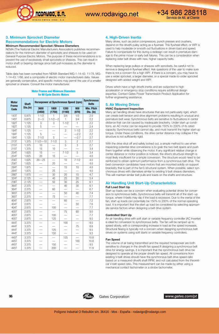
3. Minimum Sprocket Diameter
Recommendations for Electric MotorsMinimum Recommended Sprocket /Sheave Diameters
NEMA (The National Electric Manufacturers Association) publishes recommen-
dations for the minimum diameter of sprockets and sheaves to be used on
General Purpose Electric Motors. The purpose of these recommendations is to
prevent the use of excessively small sprockets or sheaves. This can result in
motor shaft or bearing damage since belt pull increases as the diameter is
reduced.
Table data has been compiled from NEMA Standard MG-1-14-42; 11/78, MG-
1-14-43; 1/68, and a composite of electric motor manufacturers data. Values
are generally conservative, and specific motors may permit the use of a smaller
sprocket or sheave. Consult the motor manufacturer.
Motor Frames and Minimum Diameters
for 60 Cycle Electric Motors
4. High-Driven InertiaMany drives, such as piston compressors, punch presses and crushers,
depend on the driveN pulley acting as a flywheel. This flywheel effect, or WR2 is
used to help moderate or smooth out fluctuations in driven load and speed.
Failure to compensate for this during a redesign can result in premature dam-
age to the prime mover or early belt failures. This can be a consideration when
replacing older belt drives with new, higher capacity belts.
When replacing large pulleys or sheaves with sprockets, be careful not to
remove a designed-in flywheel effect. Ask questions of the user to make sure
there is not a concern for a high WR2. If there is a concern, you may have to
use a wider sprocket, a larger diameter, or a special made-to-order sprocket
designed with added weight and WR2.
Drives which have a high driveN inertia and are subjected to high
acceleration or emergency stop conditions require additional design
expertise. Contact Gates Power Transmission Product Application for
further engineering assistance.
5. Air Moving DrivesHVAC Equipment Inspection
Many air handling drives have structures that are not particularly rigid, which
can create belt tension and drive alignment problems resulting in unusual and
premature belt wear. Synchronous belts are sensitive to fluctuations in center
distance that can be caused by inadequate bracketry. Under start up condi-
tions, an AC motor can be required to provide 150% to 200% of its rated
capacity. Synchronous belts cannot slip, and must transmit the higher start-up
torque. Under these conditions, the drive center distance may collapse if the
structure is not sufficiently rigid.
With the drive shut off and safely locked out, a simple method to use when
inspecting potential drive conversions is to grab the two belt spans and push
them together while observing the motor. If any significant relative change in
center distance or motor position is noticed, the drive’s structural strength is
most likely insufficient for a simple conversion. The structure would need to be
reinforced to obtain optimum performance from a synchronous belt drive. The
best conversion candidates have motors that are mounted solidly on support
bracketry that is part of the fan’s structural system. When possible, select syn-
chronous drives with diameters similar to existing V-belt sheave diameters.
This will maintain similar belt pulls and loads on the shafts and structure.
Air Handling Unit Start-Up CharacteristicsFull Load Start Up
Start up loads can be a concern when evaluating potential drives for conver-
sion to synchronous belts. Synchronous belts will transmit all of the start- up
torque, where V-belts may slip if the load is excessive. Due to the inertia of the
fan, start up loads can potentially be 150% to 200% of the normal operating
load. It is important that the start up load be considered by selecting appropri-
ate service factors when designing a belt drive system.
Controlled Start Up
An air handling drive with soft start or variable frequency controller (AC Inverter)
is ideal for conversion to synchronous belts. The fan will be ramped up to
speed slowly, with a corresponding increase in load as the speed increases.
Structural flexing is typically not a concern when designing synchronous belt
drives on systems using soft starts or variable frequency controllers.
Fan Speed
The volume of air being transmitted and the required horsepower are both
sensitive to changes in the driveN fan speed.If designing a synchronous belt
drive for energy savings, it is important that the synchronous belt drive be
designed to operate at the proper driveN fan speed. All conversions from
existing V-belt drives should have the synchronous belt drive speed ratio
based on a measured driveN shaft RPM, and not calculated from the theoreti-
cal V-belt speed ratio. This measurement can be made by either using a
mechanical contact tachometer or a strobe tachometer.
Motor
Frame
Code
Shaft
Dia.(in)
Horsepower at Synchronous Speed (rpm)Synchronous
Belts
3600
(3450)
1800
(1750)
1200
(1160)
900
(870)
Min. Pitch
Dia. (in)
143T
145T
0.875
0.875
1-1/2
2—3
1
1-1/2—2
3/4
1
1/2
3/4
2.0
2.2
182T
182T
1.125
1.125
3
5
3
—
1-1/2
—
1
—
2.2
2.4
184T
184T
184T
1.125
1.125
1.125
—
5
7-1/2
—
—
5
2
—
—
1-1/2
—2.2
—2.7
2.2
2.2
2.7
213T 1.375 7-1/2—10 7-1/2 3 2 2.7
215T
215T
1.375
1.375
10
15
—
10
5
—
3
—
2.7
3.4
254T
254T
1.625
1.625
15
20
—
15
7-1/2
—
5
—
3.4
4.0
256T
256T
1.625
1.625
20—25
—
—
20
10
—
7-1/2
—
4.0
4.0
284T
284T
1.875
1.875
—
—
—
25
15
—
10
—
4.0
4.0
286T 1.875 — 30 20 15 4.7
324T 2.125 — 40 25 20 5.4
236T 2.125 — 50 30 25 6.1
364T
364T
2.375
2.375
—
—
—
60
40
—
30
—
6.1
6.7
365T
365T
2.375
2.375
—
—
—
75
50
—
40
—
7.4
7.7
404T
404T
404T
2.875
2.875
2.875
—
—
—
—
—
100
60
—
—
—
50
—
7.2
7.6
7.7
405T
405T
405T
2.875
2.875
2.875
—
—
—
—
100
125
75
—
—
60
—
—
9.0
7.7
9.5
444T
444T
444T
444T
3.375
3.375
3.375
3.375
—
—
—
—
—
—
125
150
100
—
—
—
—
75
—
—
9.0
8.6
9.5
9.5
445T
445T
445T
445T
3.375
3.375
3.375
3.375
—
—
—
—
—
—
150
200
125
—
—
—
—
100
—
—
10.8
10.8
9.5
11.9
Polígono Indutrial O Rebullón s/n. 36416 - Mos - España - [email protected]
The Driving Force in Power Transmission.www.gates.com/pt 97®
The horsepower requirement for fans varies with the cube of the fan speed.
A small change in the fan speed makes a much larger difference in the
actual horsepower and energy required.
Formula 9
HP1 /HP2 =(RPM1 /RPM2 )3
Where: HP1 = Initial HorsepowerHP2 = New Horsepower @ New Fan RPMRPM1 = Initial Fan RPMRPM2 = New Fan RPM
Air-Cooled Heat Exchanger (ACHE) Applications
Air-cooled heat exchangers are used in Petrochemical, Oil and Gas
Production, Power Generation, and Petroleum Refining Industries where
process heat must be removed. Electric motors as large as 60 hp commonly
drive the cooling fans with either large ratio V-belt or Synchronous belt drives.
According to the American Petroleum Institute (API 661 - Air-Cooled Heat
Exchangers for General Refinery Service), a safety factor of 1.8 must be
used in the belt drive design process. Synchronous belt drives typically have
higher horsepower capacities than V-belt drives with an equivalent width.
This increased capacity results in narrower belt drives and lighter drive hard-
ware. Synchronous belt drive systems are especially beneficial on higher
horsepower heat exchanger units, and they are commonly used on new or
redesigned units. V-belt drive systems are commonly used on low to medi-
um HP fans because of their relatively low cost and good availability.
Surface rust on sheaves and sprockets is very abrasive, and rapidly wears
belts. Sprockets on wet heat exchanger applications (water drawn through
heat exchanger coils by fan) such as Cooling Towers, often rust and require
the use of electroless nickel plating to prevent excessive corrosion. Cooling
Towers are commonly used to cool large buildings (HVAC; Heating-Ventilating
-Air Conditioning Systems). Misalignment is a common cause of premature
belt failures on ACHE drive systems. Care should be taken to ensure proper
sheave/sprocket alignment when installing the belt drive system.
See Gates Belt Drive Preventative Maintenance and Safety Manual
for detailed information about proper belt drive alignment. Proper belt pre-
tension is necessary to obtain optimum belt performance. This is particularly
true for the high inertia start up loads seen in ACHE applications. If belt
installation tension is too low, V-belts will be prone to slippage and synchro-
nous belts will be prone to tooth jump or ratcheting. Motor controllers are
sometimes used to bring the fan up to speed slowly (soft start), decreasing
the chance of synchronous belt ratcheting.
6. Linear Motion DrivesIn linear motion drives, such as a rack and pinion application, the belt is not
transmitting a load in the conventional rotational manner. The two cut ends
of the belt are connected to clamping fixtures and the belt travels back and
forth a specified distance while rotating over a sprocket. Because of these
characteristics, the drive design process will typically not follow standard
catalog design procedures.
The designer will most likely have available a maximum belt load or pull
which will need to be related to the belt's allowable working tension.
Reasonably sized sprocket diameters are still required to prevent excessive
stress fatigue in the belt. In these applications, the designer may either use
endless belts and cut them, or use standard long length belting when avail-
able. Gates Power Transmission Product Application may be consulted for
design assistance.
7. High Performance Vehicle ApplicationsFor special high performance applications, such as motorcycles or race car
and boat supercharger drives, the design loads will typically exceed pub-
lished data. Because of the extremely high loads and speeds (as much as
500 HP and belt speeds exceeding 10,000 fpm), it is necessary for the
designer to contact Gates Power Transmission Product Application for addi-
tional assistance.
Although special considerations may be involved, it is important to remem-
ber that reasonable drive recommendations can be provided to the designer
in most cases.
8. Belt Drive RegistrationThe three primary factors contributing to belt drive registration (or position-
ing) errors are belt elongation, backlash, and tooth deflection. When evaluat-
ing the potential registration capabilities of a synchronous belt drive, the sys-
tem must first be determined to be either static or dynamic in terms of its
registration function and requirements.
Static Registration: A static registration system moves from its initial static
position to a secondary static position. During the process the designer is
concerned only with how accurately and consistently the drive arrives at its
secondary position. Potential registration errors that occur during transport
are not considered. Therefore, the primary factor contributing to registration
error in a static registration system is backlash. The effects of belt elongation
and tooth deflection do not have any influence on the registration accuracy
of this type of system.
Dynamic Registration: A dynamic registration system is required to per-
form a registering function while in motion with torque loads varying as the
system operates. In this case, the designer is concerned with the rotational
position of the drive sprockets with respect to each other at every point in
time. Therefore, belt elongation, backlash, and tooth deflection will all con-
tribute to registrational inaccuracies.
Further discussion about each of the factors contributing to registration error
is as follows:
Belt Elongation: Belt elongation, or stretch, occurs naturally when a belt is
placed under tension. The total tension exerted within a belt results from
installation as well as working loads. The amount of belt elongation is a func-
tion of the belt tensile modulus, which is influenced by the type of tensile cord
and the belt construction. The standard tensile cord used in rubber synchro-
nous belts is fiberglass. Fiberglass has a high tensile modulus, is dimensionally
stable, and has excellent flex-fatigue characteristics. If a higher tensile modu-
lus is needed in a rubber synchronous belt, aramid tensile cords can be con-
sidered, although they are generally used to provide resistance to harsh shock
and impulse loads. Aramid tensile cords used in rubber synchronous belts
generally have only a marginally higher tensile modulus in comparison to fiber-
glass. When needed, belt tensile modulus data is available from Gates Power
Transmission Product Application.
Backlash: Backlash in a synchronous belt drive results from clearance
between the belt teeth and the sprocket grooves. This clearance is needed to
allow the belt teeth to enter and exit the grooves smoothly with a minimum of
interference. The amount of clearance necessary depends upon the belt tooth
profile. PowerGrip® Timing Belt Drives are known for having relatively little
backlash. PowerGrip® HTD® Drives have improved torque carrying capability
and resist ratcheting, but have a significant amount of backlash, PowerGrip®
GT®2 and Poly Chain® GT® Carbon® Drives have considerably improved
torque carrying capability, and backlash characteristics in between that of
PowerGrip HTD and PowerGrip Timing Drives. In special cases, alterations
can be made to drive systems to further decrease backlash. These alterations
often result in increased belt wear, increased drive noise and shorter drive life.
For additional information contact Gates Power Transmission Product
Application.
Tooth Deflection: Tooth deformation in a synchronous belt drive occurs as
a torque load is applied to the system, and individual belt teeth are loaded.
The amount of belt tooth deformation depends upon the amount of torque
loading, sprocket size, installation tension and belt type. Of the three primary
contributors to registration error, tooth deflection is the most difficult to
quantify. Experimentation with a prototype drive system is the best means
of obtaining realistic estimations of belt tooth deflection. Additional guide-
lines that may be useful in designing registration critical drive systems are
as follows:
• Design with large sprockets with more teeth in mesh.
• Keep belts tight, and control tension closely.
• Design frame/shafting to be rigid under load.
• Use high quality machined sprockets to minimize radial run
out and lateral wobble.
Polígono Indutrial O Rebullón s/n. 36416 - Mos - España - [email protected]

Gates Corporation www.gates.com/pt98 ®
9. Belt Drive NoiseV-belt, synchronous belt, roller chain, and gear drives will all generate noise
while transmitting power. Each type of system has its own characteristic
sound. V-belt drives tend to be the quietest and synchronous belt drives are
much quieter than roller chain drives. When noise is an issue, there are sev-
eral design and maintenance tips that should be followed to minimize belt
drive noise.
Noise: Decibel and Frequency
Noise is an unwanted or unpleasant sound that can be described with two
criteria – frequency and decibel (dB) levels. Frequency is measured in Hertz.
A perfect human ear is capable of distinguishing frequencies typically from
20 to 20,000 Hertz. The human ear does not generally perceive frequencies
higher than 20,000 Hertz. The sound pressure level or intensity of noise is
measured in terms of decibels (dB). The decibel has become the basic unit
of measure since it is an objective measurement that approximately corre-
sponds to the subjective measurement made by the human ear. Since
sound is composed of several distinct and measurable parts and the
human ear doesn’t differentiate between these parts, measuring scales that
approximate the human ear’s reaction have been adopted. Three scales –
A, B, and C – are used to duplicate the ear’s response over the scale’s
ranges. The A scale is most commonly used in industry because of its
adoption as the standard in OSHA regulations. Noise described in decibels
(dBA -“A” weighting for the human ear) is generally perceived as the loud-
ness or intensity of the noise.
While the human ear can distinguish frequencies over a broad range, the
ear is most sensitive in the range of normal speech – 500 to 2000 Hertz..
As a consequence, this is the range most commonly of concern for noise
control (“A” weighting gives more weight or emphasis to sounds in the 500
to 2000 hz range). Frequency is most closely related to what the ear hears
as pitch. High frequency sounds are perceived as whining or piercing, while
low frequency sounds are perceived as rumbling. The combination of sound
pressure level (dB) and frequency describes the overall level of loudness
perceived by the human ear. One without the other does not adequately
describe the loudness potential of the noise. For example, an 85 dBA noise
at 3000 Hertz is going to be perceived as being much louder than an 85
dBA noise at 500 Hertz.
Reducing Noise
Following proper installation and maintenance procedures, as well as some
simple design alternatives can reduce belt drive noise.
Belt Drive Tension and Alignment
Properly tensioning and aligning a belt drive will allow the belt drive to per-
form at its quietest level. Improper tension in synchronous belt drives can
affect how the belt fits in the sprocket grooves. Proper tension minimizes
tooth to groove interference, and thereby reduces belt noise.
Misaligned synchronous belt drives tend to be much noisier than properly
aligned drives due to the amount of interference that is created between the
belt teeth and the sprocket grooves. Misaligned synchronous belt drives
also may cause belt tracking that forces the edge of the belt to ride hard
against a sprocket flange. Misalignment causing belt contact with a flange
will generate noise that is easily detected.
Noise Barriers and Absorbers
Sometimes, even properly aligned and tensioned belt drives may be too
noisy for a work environment. When this occurs, steps can be taken to
modify the drive guard to reduce the noise level.
Noise barriers are used to block and reflect noise. Noise barriers do not
absorb or deaden the noise; they block the noise and generally reflect most
of the noise back towards its point of origin. Good noise barriers are dense,
and should not vibrate. A sheet metal belt guard is a noise barrier. The more
complete the enclosure is, the more effective it is as a noise barrier. Noise
barrier belt guards can be as sophisticated as a completely enclosed case,
or as simple as sheet metal covering the front of the guard to prevent direct
sound transmission.
Noise absorbers are used to reduce noise reflections and to dissipate noise
energy. Noise absorbers should be used in combination with a noise barrier.
Noise absorbers are commonly referred to as acoustic insulation. Acoustic
insulation (the noise absorber) is used inside of belt guards (the noise barri-
er) where necessary. A large variety of acoustic insulation manufacturers are
available to provide different products for the appropriate situation.
A combination of noise barrier (solid belt guard) and noise absorber
(acoustic insulation) will provide the largest reduction in belt drive noise.
While the noise reduction cannot be predicted, field experience has shown
that noise levels have been reduced by 10 to 20 dBA when using complete
belt guards with acoustic insulation.
10. Use of Flanged SprocketsGuide flanges are needed in order to keep the belt on the sprocket. Due to
tracking characteristics, even on the best aligned drives, belts will ride off
the edge of the sprockets. Flanges will prevent this belt ride-off.
On all drives using stock or made-to-order sprockets, the following condi-
tions should be considered when selecting flanged sprockets:
1. On all two-sprocket drives, the minimum flanging requirements are
two flanges on one sprocket or one flange on each sprocket on
opposite sides.
2. On drives where the center distance is more than eight times the
diameter of the small sprocket, both sprockets should be flanged on
both sides. (See Engineering Section II, Drive Alignment and Belt
Installation on Pages 105 and 106.)
3. On vertical shaft drives, one sprocket should be flanged on both
sides, and all the other sprockets in the system should be flanged on
the bottom side only.
4. On drives with more than two sprockets, the minimum flanging
requirements are two flanges on every other sprocket or one flange
on every sprocket —on alternating sides around the system.
On made-to-order sprockets, flanges must be securely fastened, such as
using mechanical fasteners, welding, shrink-fit or other equivalent methods.
11. Fixed (Nonadjustable) Center DistanceDesigners sometimes attempt to design synchronous belt drive systems
without any means of belt adjustment or take up. This type of system is
called a Fixed Center Drive. While this approach is often viewed as being
economical, and is simple for assemblers, it often results in troublesome reli-
ability and performance problems in the long run.
The primary pitfall in a fixed center design approach is failure to consider the
affects of system tolerance accumulation. Belts and sprockets are manufac-
tured with industry accepted production tolerances. There are limits to the
accuracy that the center distance can be maintained on a production basis
as well. The potential effects of this tolerance accumulation is as follows:
Low Tension:
Long Belt with Small Sprockets on a Short Center Distance
High Tension:
Short Belt with Large Sprockets on a Long Center Distance
Belt tension in these two cases can vary by a factor of 3 or more with a
standard fiberglass tensile cord, and even more with an aramid tensile cord.
This potential variation is great enough to overload bearings and shafting, as
well as the belts themselves. The probability of these extremes occurring is
a matter of statistics, but however remote the chances seem, they will
occur in a production setting. In power transmission drives, the appearance
of either extreme is very likely to impact drive system performance in a neg-
ative manner.
Polígono Indutrial O Rebullón s/n. 36416 - Mos - España - [email protected]
The Driving Force in Power Transmission.www.gates.com/pt 99®
The most detrimental aspect of fixed center drives is generally the potentially
high tension condition. This condition can be avoided by adjusting the design
center distance. A common approach in these designs is to reduce the cen-
ter distance from the exact calculated value by some small fraction. This
results in a drive system that is inherently loose, but one that has much less
probability of yielding excessively high shaft loads. NOTE: This approach
should not be used for power transmission drives since the potentially loose
operating conditions could result in accelerated wear and belt ratcheting,
even under nominal loading.
There are times when fixed center drive designs can’t be avoided. In these
cases, the following recommendations will maximize the probability of suc-
cess.
1. Do not use a fixed center design for power transmission drives.
Consider using a fixed center design only for lightly loaded or motion
transfer applications.
2. Do not use a fixed center design for drives requiring high motion
quality or registration precision.
3. When considering a fixed center design, the center distance must be
held as accurately as possible, typically within 0.002”— 0.003”
(0.05mm — 0.08mm). This accuracy often requires the use of stamped
steel framework.
4. Sprockets for fixed center systems should be produced with a machin-
ing process for accuracy. Molding and sintering processes are generally
not capable of holding the finished O.D. sufficiently accurate for these
systems.
5. The performance capabilities of the drive system should be verified by
testing belts produced over their full length tolerance range on drive
systems representing the full potential center-distance variation.
Contact Gates Power Transmission Product Application for further
details.
6. Contact Gates Power Transmission Product Application for design cen-
ter distance recommendations and application assistance.
12. Use of IdlersUse of idlers should be restricted to those cases in which they are func-
tionally necessary. Idlers are often used as a means of applying tension
when the center distance is not adjustable.
Idlers should be located on the slack side span of the belt drive. General
size recommendations are listed for inside grooved, inside flat, and back-
side idlers. In some cases, such as high capacity drives utilizing large
sprockets, idlers as large as the smallest loaded sprocket in the system
may be more appropriate.
Idler Size Recommendations
Outside or backside idlers should be flat and uncrowned; flanges may or
may not be necessary. Drives with flat inside idlers should be tested, as
noise and belt wear may occur.
Idler arc of contact should be held to a minimum. All idlers should be rigid-
ly mounted in place to minimize movement or deflection during drive start-
up and operation.
13. Specifying Shaft Locations in
Multipoint Drive LayoutsWhen collecting geometrical layout data for multiple sprocket drive layouts, it
is important to use a standard approach that is readily understood and
usable for drive design calculations. This is of particular importance when the
data will be provided to Gates Power Transmission Product Application for
analysis. Drive design software that allows designers to design multipoint
drives can also be downloaded at www.gates.com/drivedesign.
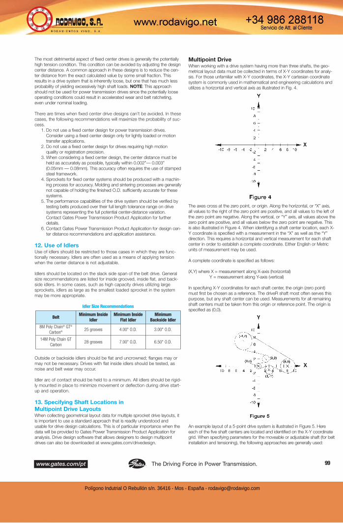
Multipoint DriveWhen working with a drive system having more than three shafts, the geo-
metrical layout data must be collected in terms of X-Y coordinates for analy-
sis. For those unfamiliar with X-Y coordinates, the X-Y cartesian coordinate
system is commonly used in mathematical and engineering calculations and
utilizes a horizontal and vertical axis as illustrated in Fig. 4.
The axes cross at the zero point, or origin. Along the horizontal, or “X” axis,
all values to the right of the zero point are positive, and all values to the left of
the zero point are negative. Along the vertical, or “Y” axis, all values above the
zero point are positive, and all values below the zero point are negative. This
is also illustrated in Figure 4. When identifying a shaft center location, each X-
Y coordinate is specified with a measurement in the “X” as well as the “Y”
direction. This requires a horizontal and vertical measurement for each shaft
center in order to establish a complete coordinate. Either English or Metric
units of measurement may be used.
A complete coordinate is specified as follows:
(X,Y) where X = measurement along X-axis (horizontal)
Y = measurement along Y-axis (vertical)
In specifying X-Y coordinates for each shaft center, the origin (zero point)
must first be chosen as a reference. The driveR shaft most often serves this
purpose, but any shaft center can be used. Measurements for all remaining
shaft centers must be taken from this origin or reference point. The origin is
specified as (0,0).
An example layout of a 5-point drive system is illustrated in Figure 5. Here
each of the five shaft centers are located and identified on the X-Y coordinate
grid. When specifying parameters for the moveable or adjustable shaft (for belt
installation and tensioning), the following approaches are generally used:
BeltMinimum Inside
Idler
Minimum Inside
Flat Idler
Minimum
Backside Idler
8M Poly Chain® GT®
Carbon®25 grooves 4.00" O.D. 3.00" O.D.
14M Poly Chain GT
Carbon28 grooves 7.00" O.D. 6.50" O.D.
Polígono Indutrial O Rebullón s/n. 36416 - Mos - España - [email protected]

Gates Corporation www.gates.com/pt100 ®
Fixed Location: Specify the nominal shaft location coordinate with a move-
ment direction.
Slotted Location: Specify a location coordinate for the beginning of the slot,
and a location coordinate for the end of the slot along its path of linear move-
ment.
Pivoted Location: Specify the initial shaft location coordinate along with a
pivot point location coordinate and the pivot radius.
Performing belt length and idler movement/positioning calculations by hand
can be quite difficult and time consuming. With a complete geometrical drive
description, we can make the drive design and layout process quite simple
for you. Contact Gates Power Transmission Product Application for comput-
er-aided assistance.
14. Minimum Belt Wrap and Tooth Engagement
Horsepower ratings listed in this catalog are based on a minimum of six
teeth in mesh between the belt and the sprocket. The ratings must be cor-
rected for excessive tooth loading if there are less than six teeth in mesh.
For non-stock drives not listed in the Drive Selection Tables, the teeth in
mesh may be calculated by using this formula:
Formula 10
Where: D = pitch diameter, large sprocket, inches
d = pitch diameter, small sprocket, inches
C = center distance between shafts, inches
Ng = number of grooves in small sprocket
In cases where fewer than six teeth are in full contact, 20% of the horse-
power rating must be subtracted for each tooth less than six not in full
contact. After computing the teeth in mesh, the belt rating should be mul-
tiplied by the appropriate KTM factor shown in the following table.
Teeth In Mesh Correction Factor
In addition to the number of teeth in mesh, some drives with more than two
shafts may have a greater potential for the belts to ratchet where loaded
sprockets have six teeth in mesh, but a small arc of contact. In order to mini-
mize this condition, each loaded sprocket in the drive system should have an
arc of contact or belt wrap angle of at least 60 degrees. Non-loaded idler
sprockets do not have tooth meshing or wrap angle requirements.
15. Adverse Operating EnvironmentsDebris
Be very careful when using synchronous drives in high debris environments.
Debris can be more damaging to the positive belt drive than a V-belt drive,
which has a tendency to remove debris from the sheave grooves through
drive operation. Entrapment of debris in synchronous drives is a major con-
cern. Debris can be packed into sprocket grooves causing improper belt
tooth engagement, reducing belt life and accelerating belt and sprocket wear.
Care must be taken to provide adequate shielding to drives in environments
where debris is likely. Completely enclosing a synchronous belt drive may be
acceptable. Since synchronous belts generate minimal heat during drive
operation, air circulation is not critical except where extremely high tempera-
tures already are present. Depending on the type and abrasive characteristics
of the debris, excessive wear can be generated on both belt and sprockets.
Temperature
Belt performance is generally unaffected in ambient temperature environ-
ments between -65° and 185°F (-54° and 85°C). Temperature extremes
beyond these limits should be reviewed by Gates Power Transmission
Product Application.
High Humidity/Corrosive Environments
Many industrial applications face problems associated with rusting parts.
Numerous applications in the food and beverage industry are located in areas
that require periodic washdown. Unless a drive is completely shielded and
protected from wash down, rust and corrosion will be rapidly apparent in
these types of environments. This is equally true of sprockets when used in
very wet or humid environments, such as seen with air moving drives on
cooling towers or wood kilns. The constant effects of the wet air surrounding
the belt drive can cause excessive rust.
Corrosion attacks sprocket grooves, building up rust deposits. The
corrosion will increase over time, building up in the sprocket grooves and
non-driving surfaces (flanges, sprocket faces, bushing face). Sprockets with
corrosion in the grooves will rapidly wear the belt’s teeth and wear through
the abrasion resistant tooth fabric, resulting in tooth shear and premature belt
failure.
When an application is in a corrosive environment, the designer may elect
to use special sprockets and bushings to prevent premature
failures. Using special stainless steel sprockets and bushings or
electroless nickel-plated sprockets can help eliminate corrosion as a cause
of failure on belt drives located in these damaging environments.
Section II
Engineering Design Considerations
All synchronous belt drives require proper installation procedures for opti-
mum performance. In addition, topics such as tooth profile advantages,
sprocket rim speed limitations, efficiency, and tolerances are common to
all Gates synchronous belt drives.
1. Belt Storage and Handling
2. Center Distance and Belt Length
3. Tooth Profiles
4. Static Conductivity
5. Sprocket Diameter-Speed
6. Efficiency
7. Belt Tolerances
8. Belt Installation Tension
9. Center Distance Allowances for Installation and Tensioning
10. Drive Alignment
11. Belt Installation
12. Belt Pull Calculations
13. Bearing/Shaft Load Calculations
14. Self-Generated Tension
Teeth in Mesh Factor KTM
6 or more 1.00
5 0.80
4 0.60
3 0.40
2 0.20
Polígono Indutrial O Rebullón s/n. 36416 - Mos - España - [email protected]

The Driving Force in Power Transmission.www.gates.com/pt 101®
Each of these circumstances and special considerations are reviewed
below.
1. Belt Storage and HandlingStorage Recommendations
In order to retain their serviceability and dimensions, proper storage pro-
cedures must be followed for synchronous belts. Quite often premature
belt failures can be traced to improper belt storage procedures that dam-
aged the belt before it was installed on the drive. By following a few
guidelines, these types of belt failures can be avoided.
Recommended
Belts should be stored in a cool and dry environment with no direct sun-
light. Ideally, belts should be stored at less than 85°F and with lower than
70% relative humidity.
Belts should be stored in original packaging.
Not Recommended
Belts should not be stored near windows, which may expose the belts to
direct sunlight or moisture.
Belts should not be stored near heaters, radiators, or in the direct airflow of
heating devices.
Belts should not be stored near any devices that generate ozone such as
transformers and electric motors.
Belts should not be stored where they are exposed to solvents or chemicals
in the atmosphere.
Do not store belts on the floor unless they are in a protective container. Floor
locations are exposed to traffic that may damage the belts.
Do not crimp belts during handling or while being stored. To avoid this, belts
must not be bent to diameters smaller than what is recommended (minimum
recommended sprocket diameter for inside bends and 1.3 times the mini-
mum recommended sprocket diameter for back side bends). Do not use ties
or tape to pull belt spans tightly together near the end of the belt. Do not
hang on a small diameter pin that suspends all of the belt weight and bends
the belt to a diameter smaller than the minimum recommended sprocket
diameter. Improper storage will damage the tensile cord and the belt will fail
prematurely. Handle belts carefully when removing from storage and moving
to the application.
Storage Effects
Belts may be stored up to six years if properly stored at temperatures less
than 85°F and relative humidity less than 70%.
For every 15°F increase in storage temperature above 85°F, the time the belt
can be stored without reduced performance decreases by one-half. Belts
should never be stored at temperatures above 115°F.
At relative humidity levels above 70%, fungus or mildew may form on stored
belts. This has minimal affect on belt performance, but should be avoided if
possible. When equipment is stored for prolonged periods of time (over six
months), the belt tension should be relaxed so that the belt does not take a
set, and the storage environment should meet the 85°F and 70% or less rel-
ative humidity condition. If this is not possible, belts should be removed and
stored separately in a proper environment.
2. Center Distance and Belt LengthThe approximate relationship between a center distance and
belt pitch length is given by the following formula:
Formula 11
Where: Lp = belt pitch length, inches
D = diameter of large sprocket, inches
d = diameter of small sprocket, inches
C = center distance, inches
A more precise formula is given below:
Formula 12
Where: Lp = belt pitch length, inches
C= center distance, inches
D = pitch diameter of large sprocket, inches
d = pitch diameter of small sprocket, inches
The approximate center distance can be found by this formula:
Formula 13
Where: K = 4 Lp – 6.28 (D+d)
The exact center distance can be calculated using an iterative process
between the center distance (Formula 13) and belt length (Formula 12)
equations. The exact center distance has been found when the two equa-
tions converge. The pitch length increment of a synchronous belt is equal
to a multiple of the belt pitch.
3. Tooth ProfilesConventional trapezoidal belts (MXL, XL, etc.) were the earliest developments
of positive drive belts. In more recent years, new curvilinear profiles have
entered the market. The most predominant of these profiles is the HTD®
system (5mm, 8mm, etc.). While these curvilinear profiles provide many
advantages, they also can provide significant disadvantages.
With the development of the Gates GT® tooth profile, the combined advan-
tages of the various curvilinear profiles have now been optimized.
Characteristics such as ratcheting resistance, improved load/life and noise
reduction were prime factors in the design of the Gates GT profile.
Additionally, it allowed optimization in incorporating premium materials into its
superior construction.
The GT tooth profile is based on the tractix mathematical function.
Engineering handbooks describe this function as a “frictionless” system. This
early development by Schiele is described as an involute form of a catenary.
With this system, the belt and sprocket teeth move substantially tangentially
during entry and exit, thus improving significantly the belts’ performance
characteristics. This is illustrated in Fig. 6. For information on belt/ sprocket
interchangeability between various Gates products as well as interchange
with other manufacturers, consult Gates Belt/Sprocket Interchange Guide
(12998-B) or contact Power Transmission Product Application.
Figure 6
Polígono Indutrial O Rebullón s/n. 36416 - Mos - España - [email protected]

Gates Corporation www.gates.com/pt102 ®
4. Static ConductivityStatic discharge can pose a hazard on belt drives that operate in potentially
explosive environments. Static discharge can also interfere with radios, elec-
tronic instruments, or controls used in a facility. While uncommon, static dis-
charge can also cause bearing pitting if the discharge occurs through the
bearing. Static conductivity is a required belt characteristic in these cases in
order to prevent static discharge.
The Rubber Manufacturer’s Association (RMA) has published Bulletin IP 3-
3 for static conductivity. Static conductivity testing involves using an ohmmeter
to pass an electrical current with a nominal open circuit 500 volt potential
through a belt. The test should be performed with the belt off of the belt drive.
The belt’s resistance is measured by placing electrodes 8.5 inches apart on the
clean driving surface of the belt. A resistance reading of six (6) megohms or
more constitutes a test failure. Belts that measure a resistance of 6 megohms
or more are considered to be non-conductive. Belts that measure a resistance
of less than 6 megohms are considered to be static conductive. A static con-
ductive belt with a resistance of 6 megohms or less has sufficient conductivity
to prevent measurable static voltage buildup, thus preventing a static discharge.
When a belt is used in a hazardous environment, additional protection must
be employed to assure that there are no accidental static spark discharges.
The portion of the belt that contacts the sprocket must be conductive to
ensure that static charge is conducted into the drive hardware. Synchronous
belts must have a static conductive tooth surface in contact with conductive
sprocket grooves. Unusual or excessive debris or contaminant on the belt
contact surface or sprocket grooves should be cleaned and removed.
Any belt drive system that operates in a potentially hazardous environment
must be properly grounded. A continuous conductive path to ground is nec-
essary to bleed off the static charge. This path includes a static conductive
belt, a conductive sprocket, a conductive bushing, a conductive shaft, con-
ductive bearings, and the ground. As an additional measure of protection, a
static-conductive brush or similar device should be employed to bleed off
any residual static buildup that might remain around the belt. The user must
ensure that belt drives operating in potentially hazardous or explosive envi-
ronments are designed and installed in accordance with existing building
codes, OSHA requirements, and/or recognized safety-related organizations.
5. Sprocket Diameter —Speed
Drives shaded in the Belt Width Selection Tables use sprocket diameters
that may reduce belt life. The amount of reduction will depend on speed
— the higher the speed, the greater the reduction. The drives are included
for use where speed ratio or space requirements must be met. Blanks in
the lower right-hand portions of the Belt Width Selection Tables occur
because sprocket rim speed exceeds 6,500 feet per minute. Centrifugal
forces developed beyond this speed may prohibit the use of stock gray
cast iron sprockets. For rim speeds above 6,500 feet per minute, contact
Gates Power Transmission Product Application for other alternatives.
6. EfficiencyWhen properly designed and applied, PolyChain® GT® Carbon® belt drive
efficiency will be as high as 98%. This high efficiency is primarily due to
the positive, no slip characteristic of synchronous belts. Since the belt has
a thin profile, it flexes easily, thus resulting in low hysteresis losses as evi-
denced by low heat buildup in the belt.
Gates synchronous belts are uniquely constructed because they use high
performance materials. Optimization of these high-technology features
provide maximum performance and efficiency. Synchronous belt drive effi-
ciency can be simply defined as shown in the following equation:
When examining the loss of energy, it is necessary to consider belt losses
in terms of shaft torque and shaft speed. Torque losses result from bend-
ing stress and friction. Chain drives running unlubricated may generate
significant heat build up due to increased friction in the roller joints. Even
properly lubricated chains running at higher speeds tend to throw off the
oil due to centrifugal forces, making it difficult to maintain proper lubrica-
tion at the load bearing surfaces. Consequently, chain drives are typically
only 92-98% efficient.
Speed losses result from belt slip and creep. Unlike V-belts, slip is not a
factor with synchronous belts. Well maintained V-belt drives are typically in
the range of 95-98% efficient. However, on a poorly designed or main-
tained drive, the efficiency may drop as much as 5% or more. If proper
maintenance cannot be scheduled for a V-belt drive or it is located in an
inaccessible area, a positive belt drive system should be considered.
Increasing DriveN TorqueThe belt drive is only part of the total system. Motors should be properly
sized for the application. They must have sufficient capacity to meet the
power needs, yet over designed motors will lead to electrical inefficiencies.
DriveN machines also may have inherent inefficiencies which may con-
tribute to overall system efficiency.
dN RPM X dN TorqueEffiicency, percent = X 100dR RPM X dR Torque
Sprockets Recommended
For maximum performance, use Gates sprockets
Polígono Indutrial O Rebullón s/n. 36416 - Mos - España - [email protected]

The Driving Force in Power Transmission.www.gates.com/pt 103®
7. Belt TolerancesThese tolerances are for reference only. For fixed center drive applications
and special tolerances, contact Gates Power Transmission Product
Application.
8. Belt Installation TensionStandard Belt Tensioning Procedure
When installing a Gates belt:
A. Be sure it is tensioned adequately to prevent tooth jumping
(ratcheting) under the most severe load conditions which the
drive will encounter during operation.
B. Avoid extremely high tension which can reduce belt life and
possibly damage bearings, shafts and other drive components.
The proper way to check belt tension is to use a tension tester. Gates has
a variety of tension testers, ranging from the simple spring scale type
tester to the sophisticated Sonic Tension Meter. The spring scale type
tester is used by measuring how much force is required to deflect the belt
at the center of its span by a specified distance (force deflection method),
as shown in the sketch below.
The Sonic Tension Meter measures the vibration of the belt span and
instantly converts the vibration frequency into belt static tension (span
vibration method).
When you wish to use a numerical method for calculating recommended
belt installation tension values, the following procedure may be used.
STEP 1: Calculate the required base
static installation tension.
Use Formula 14 to calculate the required base static installation
tension.
Formula 14
Tst =20HP +mS2
S
Where: Tst = base static installation tension, pounds
HP = Horsepower
S = PD x RPM
3820
M = Value from Table 11
PD = Sprocket Pitch Diameter, inches
RPM = Revolutions per minute of same sprocket
Table 11
Pitch Belt Width M YMinimum Tst (lb)
per span
8mm
12mm
21mm
36mm
62mm
0.33
0.57
0.97
1.68
65
113
194
335
28
49
84
145
14mm
20mm
37mm
68mm
90mm
125mm
0.92
1.69
3.11
4.12
5.72
230
426
782
1035
1438
119
220
405
536
744
Stock Belt Width Tolerances
BeltPitch
Standard (mm)Belt Width (in)
(mm)Tolerances (in)
8mm
120.47
21.083
361.42
622.44
± 0.36.014
± 0.63.025
± 1.080.43
± 1.860.73
14mm
200.79
371.46
682.68
903.54
1254.92
± .060.024
± 1.11.044
± 2.04.080
± 2.70.106
± 3.75.148
Stock Belt Center Distance Tolerances
Belt Length(mm)(in)
Center Distance (mm)Tolerance (in)
over127 to 2545 10
± 0.20.008
over254 to 381 10 15
± 0.23.009
over381 to 508 15 20
± 0.25.010
over508 to 762 20 30
± 0.30.012
over762 to 1016 30 40
± 0.33.013
over1016 to 1270 40 50
± 0.38.015
over1270 to 152450 60
± 0.41.016
over1524 to 177860 70
± 0.43.017
over1778 to 203270 80
± 0.46 .018
over2032 to 228680 90
± 0.49 .019
over2286 to 254090 100
± 0.52.020
over2540 to 2794100 110
± 0.54.021
over2794 to 3048110 120
± 0.56.022
over3048 to 3302120 130
± 0.58.023
over3302 to 3556130 140
± 0.60.024
over3556 to 3810140 150
± 0.63.025
over3810 to 4064150 160
± 0.66.026
over4064 to 4318160 170
± 0.69.027
over4318 to 4572170 180
± 0.72.028
over4572180
add ± .03 for.001
every 254 increment10
Polígono Indutrial O Rebullón s/n. 36416 - Mos - España - [email protected]

Gates Corporation www.gates.com/pt104 ®
Because of the high performance capabilities of Poly Chain® GT® Carbon®
belts, it is possible to design drives that have significantly greater load
than are necessary to carry the actual design load. Consequently, Formula
14 can provide Tst values less than are necessary for the belt to operate
properly, resulting in poor belt performance and reduced service life. If a
more appropriately sized drive cannot be designed, minimum recom-
mended Tst values are provided in Table 10 to assure that the belts func-
tion properly when lightly loaded.
Always use the greater Tst value; i.e., from Tst Formula 14 or Table 11.
NOTE: When applying static belt tension values directly, multiply the
required base static installation tension (Tst) calculated in Formula 14 by
the following factors:
For New Belts:
Minimum Static Tension = Base Static Tension X 1.1
Maximum Static Tension = Base Static Tension X 1.2
For Used Belts:
Minimum Static Tension = Base Static Tension X 0.8
Maximum Static Tension = Base Static Tension X 0.9
STEP 2: Calculate the minimum and maximum
recommended deflection forces.
A. Measure the span length of your drive (see sketch).
B. New belt minimum recommended force:
Formula 15
deflection force, Min
.
C. New belt maximum recommended force:
Formula 16
deflection force, Max.
Where:
Tst = Base Static tension, lbf
t = span length, inches
L = belt pitch length, inches
Y= constant from Table 11
USED BELT NOTE: For re-installation of a used belt, a recommended ten-
sion of 0.8 Tst to 0.9 Tst value should be used in calcu-
lating the deflection forces, instead of the
1.1 Tst to 1.2 Tst shown for new belts.
STEP 3: Applying the tension.
Force deflection tension method
A. At the center of the span (t) apply a force perpendicular to the span large
enough to deflect the belt on the drive 1/64 inch per inch of span length
from its normal position. One sprocket should be free to rotate. Be sure
the force is applied evenly across the entire belt width. If the belt is a
wide synchronous belt, place a piece of steel or angle iron across the
belt width and deflect the entire width of the belt evenly.
B. Compare this deflection force with the range of forces calculated in
Step 2.
1. If it is less than the minimum recommended deflection force, the
belt should be tightened.
2. If it is greater than the maximum recommended deflection force,
the belt should be loosened.
Span vibration tension method
The Sonic Tension Meter detects the vibration frequency in the belt span,
and converts that measurement into the actual static tension in the belt.
To use the Sonic Tension Meter, begin by entering the belt unit weight,
belt width, and the span length. To measure the span vibration, press the
“Measure” button on the meter, tap the belt span, and hold the micro-
phone approximately 1/4” away from the back of the belt. The Sonic
Tension Meter will display the static tension, and can also display the span
vibration frequency.
The belt unit weights for use with the Gates Sonic Tension Meter are
shown in the following table.
Belt Product FamilyBelt Cross
section
Adjusted Belt Weight
(grams/meter)
Poly Chain GT Carbon8mm 4.7
14mm 7.9
Polígono Indutrial O Rebullón s/n. 36416 - Mos - España - [email protected]

The Driving Force in Power Transmission.www.gates.com/pt 105®
9. Center Distance Allowances for
Installation and TensioningSince fixed center drives are not recommended, center distance
allowances for a Gates Poly Chain® GT® Carbon® belt drive are necessary
to assure that the belt can be installed without damage and then ten-
sioned correctly. The standard installation allowance is the minimum
decrease in center distance required to install a belt when flanged
sprockets are removed from their shafts for belt installation. This is
shown in the first column of Table 12. This table also lists the minimum
increase in center distance required to assure that a belt can be properly
tensioned over its normal lifetime. If a belt is to be installed over flanged
sprockets without removing them, the additional center distance
allowance for installation shown in the second table below must be
added to the first table data.
Table 12
Center Distance Allowance For Installation and Tensioning
Additional Center Distance Allowance For Installation Over Flanged Sprockets*
(Add to Installation Allowance In Table No.12)
*For drives that require installation of the belt over one sprocket at a time, use the value
for “Both Sprockets Flanged”
10. Drive AlignmentProvision should be made for center distance adjustment, according to the
two tables on this page, or to change the idler position so the belt can be
slipped easily onto the drive. When installing a belt, never force it over the
flange. This will cause internal damage to the belt tensile member.
Synchronous belts typically are made with high modulus tensile members
which provide length stability over the belt life. Consequently, misalign-
ment does not allow equal load distribution across the entire belt top
width. In a misaligned drive, the load is being carried by only a small por-
tion of the belt top width, resulting in uneven belt wear and premature
tensile failure.
There are two types of misalignment: parallel and angular (See Fig.7).
Parallel misalignment is where the driveR and driveN shafts are parallel,
but the two sprockets lie in different planes. When the two shafts are not
parallel, the drive is angularly misaligned.
A fleeting angle is the angle at which the belt enters and exits the
sprocket, and equals the sum of the parallel and angular misalignments.
Any degree of sprocket misalignment will result in some reduction of belt
life, which is not accounted for in the normal drive design procedure.
Misalignment of all synchronous belt drives should not exceed 1/4° or
1/16" per foot of linear distance. Misalignment should be checked with a
good straight edge or by using a laser alignment tool. The straight edge
tool should be applied from driveR to driveN, and then from driveN to
driveR so that the total effect of parallel and angular misalignment is
made visible.
Figure 7
Drive misalignment can also cause belt tracking problems. However, light
flange contact by the belt is normal and won’t affect performance.
For those drives in which the center distance is greater than eight times
the small sprocket diameter, belt tracking can be a problem. In these
cases, the parallel position of the two sprockets may need to be adjust-
ed until only one flange guides the belt in the system and the belt tracks
fully on all sprockets. Regardless of the drive center distance, the opti-
mum drive performance will occur with the belt lightly contacting one
flange in the system. The worst case is for the belt to contact flanges on
opposite sides of the system. This traps the belt between opposite
flanges and can force the belt into undesirable parallel misalignment.
Length Belt (mm)(in)
Standard InstallationAllowance (FlangedSprockets Removed (mm)For Installation) (in)
Tension Allowance (All Drives) (mm)
(in)
Up to1255
0.50.02
0.50.02
Over125 to 250 5 10
0.80.03
0.80.03
Over250 to 500 10 20
1.00.04
0.80.03
Over500 to 1000 20 40
1.80.07
0.80.03
Over1000 to 1780 40 70
2.80.10
0.80.04
Over1780 to 2540 70 100
3.30.13
1.00.04
Over2540 to 3300100 130
4.10.16
1.30.05
Over3300 to 4600130 180
4.80.19
1.30.05
Over4600 to 6900180 270
5.60.22
1.30.05
PitchOne Sprocket (mm)Flanged (in)
Both Sprockets (mm)Flanged (in)
8mm21.80.86
33.31.31
14mm31.21.23
50.01.97
Polígono Indutrial O Rebullón s/n. 36416 - Mos - España - [email protected]

Gates Corporation www.gates.com/pt106 ®
Improper installation of the bushing can result in the bushing/sprocket assembly being “cocked” on the shaft. This leads toangular misalignment and sprocket wobble. Be sure to follow theinstructions provided with the bushings.
11. Belt Installation
During the belt installation process, it is very important the belt befully seated in the sprocket grooves before applying final tension.Serpentine drives with multiple sprockets and drives with largesprockets are particularly vulnerable to belt tensioning problemsresulting from the belt teeth being only partially engaged in thesprockets during installation. In order to prevent these problems,the belt installation tension should be evenly distributed to all beltspans by rotating the system by hand. After confirming that beltteeth are fully engaged in the sprocket grooves, belt tensionshould be rechecked and verified. Failure to do this may result inan undertensioned condition with the potential for belt ratcheting.
12. Belt Pull Calculations
When the machine designer requests shaft load calculations fromthe drive designer, the following procedure can be applied:
A. Calculate Belt Span Tensions
Belt pull is the vector sum of TT and TS, the tightside and slacksidetensions. TT and TS may be calculated using the following formu-las:
Formula 17
Formula 18
Where: HP = Horsepower
PD = Sprocket Pitch Diameter (in)
RPM = Sprocket Speed (rev/min)
B. Solution For Both Magnitude and Direction
The vector sum of TT and TS can be found so that the direction ofbelt pull, as well as magnitude, is known. This is necessary if beltpull is to be vectorially added to sprocket weight, shaft weight,etc., to find true bearing loads. In this case, the easiest method offinding the belt pull vector is by graphical addition of TT and TS. Ifonly the magnitude of belt pull is needed, numerical methods forvector additions are faster to use.
If both direction and magnitude of belt pull are required, the vec-tor sum of TT and TS can be found by graphical vector addition asshown in Fig. 8. TT and TS vectors are drawn to a convenient scaleand parallel to the tightside and slackside, respectively. Fig. 8shows vector addition for belt pull on the motor shaft. The sameprocedures can be used for finding belt pull on the driveN shaft.This method may be used for drives using three or more sprock-ets or idlers.
For two-sprocket drives, belt pull on the driveR and driveN shafts is equalbut opposite in direction. For drives using idlers, both magnitude anddirection may be different.
C. Solution For Magnitude Only
If only the magnitude of belt pull is needed, follow the steps below. Usethis method for drives with two sprockets. Use the graphical methodshown if the drive uses idlers.
1. Add TT and TS
2. Using the value of D - d
for the drive,C
find the vector sum correction factor usingFig. 9, where:
D = large diameter
d = small diameter
C = center distance
Or, use the arc of contact on the small
sprocket if known.
3. Multiply the sum of TT plus TS by the vector
sum correction factor to find the vector
sum of TT plus TS.
Figure 8
Figure 9
13. Bearing/Shaft Load Calculations
A. Shaft Load Calculations
If true side load on the shaft, including sprocket weight, is desired, thesprocket weight can be added to the belt pull using the same graphicalmethod shown in Fig. 8. The sprocket weight vector is vertical toward theground. Weights for standard sprockets are shown in the sprocket speci-fication tables.
Polígono Indutrial O Rebullón s/n. 36416 - Mos - España - [email protected]

B. Bearing Load Calculations
In order to find actual bearing loads, it is necessary to know weights of
machine components and the value of all other forces contributing to the
load. However, it is sometimes desirable to know the bearing load con-
tributed by the synchronous drive alone. Bearing loads resulting from a
synchronous belt drive can be calculated knowing bearing placement with
respect to the sprocket center and the shaft load as previously calculated.
For rough estimates, machine designers sometimes use belt pull alone,
ignoring sprocket weight. If accuracy is desired, or if the sprocket is
unusually heavy, actual shaft load values including sprocket weight
should be used.
C. Overhung Sprocket
Figure 10
Formula 19
Formula 20
D. Sprocket Between Bearings
Figure 11
Formula 21
Formula 22
The Driving Force in Power Transmission.www.gates.com/pt 107®
14. Self-Generated Tension
All synchronous belt drives exhibit a self-generating or self-tightening char-acteristic when transmitting a load. Laboratory testing has shown thischaracteristic to be similar with all tooth profiles. The designer/user shouldbe aware that self-tensioning can result in increased bearing and shaftloads and reduced drive performance; i.e., short belt life. This can beavoided by following proper tensioning procedures.
While belt overtensioning can impose higher bearing and shaft loads andlead to reduced belt life, undertensioning can result in self-tensioning.Properly designed and tensioned drives will not be significantly affected byself-generated tension.
When a belt is too loose for the design load, the self-tensioning character-istic results in the belt teeth climbing out of the sprocket grooves, leadingto increased stresses on the belt teeth, accelerated tooth wear andreduced belt life. When a belt is severely undertensioned, this self-tension-ing characteristic can result in the belt ratcheting (jumping teeth). Whenthis occurs, significant shaft separation forces are instantaneously devel-oped in the drive, resulting in damage to bearings, shafts, and other drivecomponents including the belt.
NOTE: This is true for all synchronous belts.
Maximum drive performance and belt life are achieved when the belt isproperly tensioned for the design load and maintained.
Polígono Indutrial O Rebullón s/n. 36416 - Mos - España - [email protected]

Gates Corporation www.gates.com/pt108 ®
Troubleshooting
Unusual noise
Tension loss
Belt tracking
Flange failure
Excessive belt edge wear
Premature tooth wear
Symptom Diagnosis Possible Remedy
Misaligned drive
Too low or high belt tension
Backside idler
Worn sprocket
Bent guide flange
Belt speed too high
Incorrect belt profile for the sprocket
(i.e., HTD® etc.)
Subminimal diameter
Excess load
Weak support structure
Excessive sprocket wear
Fixed (nonadjustable) centers
Excessive debris
Excessive load
Subminimal diameter
Belt, sprockets or shafts running too hot
Unusual belt degradation, such as softening
or melting
Belt running partly off unflanged sprocket
Centers exceed 8 times small sprocket
Excessive belt edge wear
Belt forcing flanges off
Damage due to handling
Flange damage
Belt too wide
Belt tension too low
Rough flange surface finish
Improper tracking
Belt hitting drive guard or bracketry
Too low or high belt tension
Belt running partly off unflanged sprocket
Misaligned drive
Incorrect belt profile for the sprocket(i.e., HTD, etc.)
Worn sprocket
Rough sprocket teeth
Damaged sprocket
Sprocket not to dimensional specification
Belt hitting drive bracketry or other structure
Excessive load
Insufficient hardness of sprocket material
Excessive debris
Cocked bushing/sprocket assembly
Correct alignment
Adjust tension to recommended value
Use inside idler
Replace sprocket
Replace sprocket/flange
Redesign drive
Use proper Gates Poly Chain® GT® Carbon® belt/sprocket
Redesign drive using larger diameters
Redesign drive for increased capacity
Reinforce the structure
Use alternate sprocket material
Use inside idler for belt adjustment
Protect drive
Redesign drive for increased capacity
Redesign drive using larger diameters
Check for conductive heat transfer from
prime mover
Reduce ambient drive temperature to
180°F maximum
Correct alignment
Correct parallel alignment to set belt to track onboth sprockets
Correct alignment
Correct alignment or properly secure flangeto sprocket
Follow proper handling instructions
Repair flange or replace sprocket
Use proper width sprocket
Adjust tension to recommended value
Replace or repair flange (to eliminate abrasive surface)
Correct alignment
Remove obstruction or use inside idler
Adjust tension to recommended value
Correct alignment
Correct alignment
Use proper Gates Poly Chain® GT® Carbon® belt/sprocket
Replace sprocket
Replace sprocket
Replace sprocket
Replace sprocket
Remove obstruction or use inside idler
Redesign drive for increased capacity
Use a more wear-resistant material
Protect belt
Install bushing per instructions
Polígono Indutrial O Rebullón s/n. 36416 - Mos - España - [email protected]
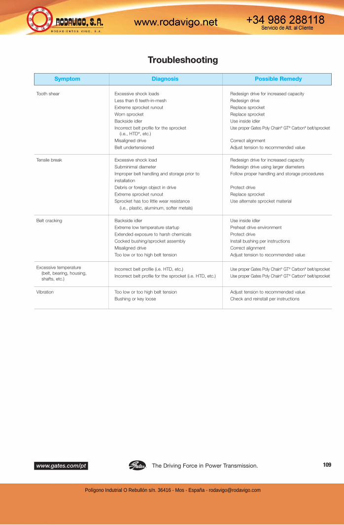
The Driving Force in Power Transmission.www.gates.com/pt 109®
Troubleshooting
Tooth shear
Tensile break
Belt cracking
Excessive temperature
(belt, bearing, housing,
shafts, etc.)
Vibration
Symptom Diagnosis Possible Remedy
Excessive shock loads
Less than 6 teeth-in-mesh
Extreme sprocket runout
Worn sprocket
Backside idler
Incorrect belt profile for the sprocket
(i.e., HTD®, etc.)
Misaligned drive
Belt undertensioned
Excessive shock load
Subminimal diameter
Improper belt handling and storage prior to
installation
Debris or foreign object in drive
Extreme sprocket runout
Sprocket has too little wear resistance
(i.e., plastic, aluminum, softer metals)
Backside idler
Extreme low temperature startup
Extended exposure to harsh chemicals
Cocked bushing/sprocket assembly
Misaligned drive
Too low or too high belt tension
Incorrect belt profile (i.e. HTD, etc.)
Incorrect belt profile for the sprocket (i.e. HTD, etc.)
Too low or too high belt tension
Bushing or key loose
Redesign drive for increased capacity
Redesign drive
Replace sprocket
Replace sprocket
Use inside idler
Use proper Gates Poly Chain® GT® Carbon® belt/sprocket
Correct alignment
Adjust tension to recommended value
Redesign drive for increased capacity
Redesign drive using larger diameters
Follow proper handling and storage procedures
Protect drive
Replace sprocket
Use alternate sprocket material
Use inside idler
Preheat drive environment
Protect drive
Install bushing per instructions
Correct alignment
Adjust tension to recommended value
Use proper Gates Poly Chain® GT® Carbon® belt/sprocket
Use proper Gates Poly Chain® GT® Carbon® belt/sprocket
Adjust tension to recommended value
Check and reinstall per instructions
Polígono Indutrial O Rebullón s/n. 36416 - Mos - España - [email protected]
Gates Corporation www.gates.com/pt110 ®
Standard Calculations
Speed ratio (R)
Horsepower (hp)(33,000 lb-ft/min)
Design horsepower (Dhp)
Power (kw)
Torque (T) in lb-in
Torque (T) in N-mm
Belt velocity in ft/min
Belt velocity in m/s
Belt pitch length (PL) in inches(approximate)
Arc of contact onsmaller pulley (A/Cs)
Torque (T) due to flywheeleffect (WR2) in lb-inches(accel. and/or decel.)
Flywheel effect (WR2) in lb-ft2
Required Given Formula
Shaft speeds (rpm)
Pulley diameter (D & d)
Number of pulley grooves (N & n)
Torque (T) in lb-inShaft speed (rpm)
Effective tension (Te) in lb.Shaft speed (rpm)
Rated horsepower (hp)Service factor (SF)
Horsepower (hp)
Shaft horsepower (hp)Shaft speed (rpm)
Effective tension (Te) in lb.Pulley radius (R) in inches
Torque (T) in lb-inches
Pulley pd in inches Pulley speed in rpm
Pulley pd in mmPulley speed in rpm
Center distance (C) in inchesPulley diameters (D & d) in inches
Pulley diameters (D & d) in inchesCenter distance (C) in inches
Final speed (RPM)Initial speed (rpm)Flywheel effect (WR2) in lb-ft2
Time (t) in seconds
Face width of rim (F) in inchesMaterial density (Z) in lbs/in3
Outside rim diameter (D) in inchesInside rim diameter (d) in inches
R =rpm (faster shaft speed)
rpm (slower shaft speed)
R =D (larger pulley diameter)
d (smaller pulley diameter)
R =N (larger pulley groove no. )
n (smaller pulley groove no. )
hp =T x rpm
63,025
hp =Te x V
33,000
Dhp = hp x SF
kw = .7457 x hp
T =63,025 x hp
rpm
T = Te x R
T = 112.98 x T
V =pd x rpm
3.82
V = .0000524 x pd x rpm
PL = 2C + [1.57 x (D + d)] + (D - d)2
(4C)
A/Cs = 180 - [ (D - d) x 60 ](4C)
T =.039 x (RPM - rpm) x WR2
t
WR2 =F x Z x (D4 -d4)
1467
Polígono Indutrial O Rebullón s/n. 36416 - Mos - España - [email protected]

The Driving Force in Power Transmission.www.gates.com/pt 111®
Useful Formulas and CalculationsPower Transmission Conversions
Other Conversions
FORCE CONVERSION CONSTANTS
Metric to U.S.
Newtons x 3.5969 = Ouncesf
Newtons x 0.2248 = Poundsf
Kilogramsf x 2.2046 = Poundsf
U.S. to Metric
Ouncesf x 0.2780 = Newtons
Poundsf x 4.4482 = Newtons
Poundsf x 0.4536 = Kilogramsf
Metric to Metric
Kilogramsf x 9.8067 = Newtons
Newtons x 0.1020 = Kilogramsf
TORQUE CONVERSION CONSTANTS
Metric to U.S.
Newton Meters x 141.6119 = Ouncef Inches
Newton Meters x 8.8508 = Poundf Inches
Newton Meters x 0.7376 = Poundf Feet
Metric to Metric
Newton Meters x 10.1972 = Kilogramf Centimeters
Kilogramf Centimeters x 0.0981 = Newton Meters
Newton Meters x 0.1020 = Kilogramf Meters
Kilogramf Meters x 9.8067 = Newton Meters
U.S. to Metric
Ouncef Inches x 0.0071 = Newton Meters
Poundf Inches x 0.1130 = Newton Meters
Poundf Feet x 1.3558 = Newton Meters
POWER CONVERSION CONSTANTS
Metric to U.S.
Kilowatt x 1.3410 = Horsepower
Watt x 0.0013 = Horsepower
U.S. to Metric
Horsepower x 745.6999 = Watt
Horsepower x 0.7457 = Kilowatt
LENGTH CONVERSION CONSTANTS
Metric to U.S.
Millimeters x 0.0394 = Inches
Meters x 39.3701 = Inches
Meters x 3.2808 = Feet
Meters x 1.0936 = Yards
Kilometers x 3280.84 = Feet
Kilometers x 0.6214 = Statute Miles
Kilometers x 0.5396 = Nautical Miles
U.S. to Metric
Inches x 25.4000 = Millimeters
Inches x 0.0254 = Meters
Feet x 0.3048 = Meters
Yards x 0.9144 = Meters
Feet x 0.0003048 = Kilometers
Statute Miles x 1.6093 = Kilometers
Nautical Miles x 1.8532 = Kilometers
AREA CONVERSION CONSTANTS
Metric to U.S.
Square Millimeters x 0.0016 = Square Inches
Square Centimeters x 0.1550 = Square Inches
Square Meters x 10.7639 = Square Feet
Square Meters x 1.1960 = Square Yards
Hectares x 2.4711 = Acres
Square Kilometers x 247.105 = Acres
Square Kilometers x 0.3861 = Square Miles
U.S. to Metric
Square Inches x 645.160 = Square Millimeters
Square Inches x 6.4516 = Square Centimeters
Square Feet x 0.0929 = Square Meters
Square Yards x 0.8361 = Square Meters
Acres x 0.4047 = Hectares
Acres x 0.004047 = Square Kilometers
Square Miles x 2.5900 = Square Kilometers
LINEAR BELT SPEED CONVERSION CONSTANTS
Metric to U.S.
Meters per second x 196.8504 = Feet per Minute
U.S. to Metric
Feet per Minute x 0.005080 = Meters per Second
Square Miles x 2.5900 = Square Kilometers
U.S. to U.S.
Feet per Second x 60.00 = Feet per Minute
Feet per Minute x 0.0167 = Feet per Second
Polígono Indutrial O Rebullón s/n. 36416 - Mos - España - [email protected]

Gates Corporation www.gates.com/pt112 ®
Useful Formulas and CalculationsOther Conversions —continued
WEIGHT CONVERSION CONSTANTS
DECIMAL AND MILLIMETER EQUIVALENTS OF FRACTIONS
Metric to U.S.
Grams x 15.4324 = Grains
Grams x 0.0353 = Ounces (Avd.)
Grams x 0.0338 = Fluid Ounces (water)
Kilograms x 35.2740 = Ounces (Avd.)
Kilograms x 2.2046 = Pounds (Avd.)
Metric Tons (1000 Kg) x 1.1023 = Net Ton (2000 lbs.)
Metric Tons (1000 Kg) x 0.9842 = Gross Ton (2240 lbs.)
U.S. to Metric
Grains x 0.0648 = Grams
Ounces (Avd.) x 28.3495 = Grams
Fluid Ounces (water) x 29.5735 = Grams
Ounces (Avd.) x 0.0283 = Kilograms
Pounds (Avd.) x 0.4536 = Kilograms
Net Ton (2000 lbs.) x 0.9072 = Metric Tons (1000 Kg)
Gross Ton (2240 lbs.) x 1.0160 = Metric Tons (1000 Kg)
Inches
Fractions Decimals Millimeters
1/64 –––––––––––––––––––––––––– .015625 .397
1/32–––––––––––––––– .03125 .794
3/64 –––––––––––––––––––––––––– .046875 1.1911
1/16 –––– .0625 1.588
5/64 –––––––––––––––––––––––––– .078125 1.984
3/32–––––––––––––––– .09375 2.3811
7/64 –––––––––––––––––––––––––– .109375 2.778
1/8 –––– .125 3.175
9/64 –––––––––––––––––––––––––– .140625 3.572
5/32–––––––––––––––– .15625 3.969
11/64 –––––––––––––––––––––––––– .171875 4.366
3/16 –––– .1875 4.763
13/64 –––––––––––––––––––––––––– .203125 5.159
7/32–––––––––––––––– .21875 5.556
15/64 –––––––––––––––––––––––––– .234375 5.953
1/4 –––– .250 6.350
17/64 –––––––––––––––––––––––––– .265625 6.7477
9/32–––––––––––––––– .28125 7.144
19/64 –––––––––––––––––––––––––– .296875 7.5411
5/16 –––– .3125 7.938
21/64 –––––––––––––––––––––––––– .328125 8.334
11/32 –––––––––––––– .34375 8.731
23/64 –––––––––––––––––––––––––– .359375 9.128
3/8 –––– .375 9.525
25/64 –––––––––––––––––––––––––– .390625 9.922
13/32 –––––––––––––– .40625 10.319
27/64 –––––––––––––––––––––––––– .421875 10.716
7/16 –––– .4375 11.113
29/64 –––––––––––––––––––––––––– .453125 11.509
15/32 –––––––––––––– .46875 11.906
31/64 –––––––––––––––––––––––––– .484375 12.303
1/2 –––– .500 12.700
Inches
Fractions Decimals Millimeters
33/64 –––––––––––––––––––––––––– .515625 13.097
17/32 –––––––––––––– .53125 13.494
35/64 –––––––––––––––––––––––––– .546875 13.89
9/16 –––– .5625 14.288
37/64 –––––––––––––––––––––––––– .578125 14.684
19/32 –––––––––––––– .59375 15.08
39/64 –––––––––––––––––––––––––– .609375 15.478
5/8 –––– .625 15.875
41/64 –––––––––––––––––––––––––– .640625 16.272
21/32 –––––––––––––– .65625 16.669
43/64 –––––––––––––––––––––––––– .671875 17.066
11/16 –––– .6875 17.463
45/64 –––––––––––––––––––––––––– .703125 17.859
23/32 –––––––––––––– .71875 18.256
47/64 –––––––––––––––––––––––––– .734375 18.653
3/4 –––– .750 19.050
49/64 –––––––––––––––––––––––––– .765625 19.44
25/32 –––––––––––––– .78125 19.844
51/64 –––––––––––––––––––––––––– .796875 20.24
13/16 –––– .8125 20.638
53/64 –––––––––––––––––––––––––– .828125 21.034
27/32 –––––––––––––– .84375 21.431
55/64 –––––––––––––––––––––––––– .859375 21.828
7/8 –––– .875 22.225
57/64 –––––––––––––––––––––––––– .890625 22.622
29/32 –––––––––––––– .90625 23.019
59/64 –––––––––––––––––––––––––– .921875 23.416
15/16 –––– .9375 23.813
61/64 –––––––––––––––––––––––––– .953125 24.209
31/32 –––––––––––––– .96875 24.606
63/64 –––––––––––––––––––––––––– .984375 25.003
1 –––––– 1.000 25.400
Polígono Indutrial O Rebullón s/n. 36416 - Mos - España - [email protected]

The Driving Force in Power Transmission.www.gates.com/pt 113®
Synchronous Belt Product Design Catalogs
Gates Synchronous Belt Products Pitch For Design Information Refer to:
Poly Chain® GT® Carbon® 8mm, 14mm Poly Chain® GT® Carbon® Belt Drive Design Manual Catalog 17595
PowerGrip® GT®2 5mm, 8mm, 14mm, 20mm PowerGrip® GT2® Belt Drive Design Manual 17195
PowerGrip® GT®2 2mm, 3mm Light Power & Precision Drives Design Manual Catalog 17183
PowerGrip® HTD® 3mm, 5mm Light Power & Precision Drives Design Manual Catalog 17183
PowerGrip® Timing XL, L, H PowerGrip GT2 Belt Drive Design Manual 17195
PowerGrip® Timing MXL, XL Light Power & Precision Drives Design Manual Catalog 17183
Poly Chain® GT2® Long Length Belting 8mm,14mm Poly Chain GT Carbon Belt Drive Design Manual 17595
PowerGrip® Timing Long Length Belting MXL, XL, L, H PowerGrip GT2 Belt Drive Design Manual 17195
PowerGrip® HTD Long Length Belting 3mm, 5mm, 8mm, 14mm PowerGrip GT2 Belt Drive Design Manual 17195
PowerGrip® GT® Long Length Belting 2mm, 3mm, 5mm, 8mm PowerGrip GT2 Belt Drive Design Manual 17195
Twin Power® XL, L, H PowerGrip Timing, 8mm, 14mm PowerGrip GT2 Belt Drive Design Manual 17195
DRIVE DESIGN SOFTWARE
Drive design software can be found atwww.gates.com/drivedesign.
This software assists designers in quicklyselecting optimum drive solutions.
Polígono Indutrial O Rebullón s/n. 36416 - Mos - España - [email protected]

World HeadquartersGates Corporation1551 Wewatta StreetDenver, Colorado 80202Tel: 303-744-1911www.gates.com
For ExportsGates InterAmericaTel: 954-926-4568Fax: [email protected]
Product ApplicationEngineersTel: [email protected]
Polígono Indutrial O Rebullón s/n. 36416 - Mos - España - [email protected]
