clinched selvage belt · pdf fileoutside openings of a ½” x 1” mesh to be...
TRANSCRIPT

MATERIALS AVAILABLE• Low carbon galvanized steel• C1050 high carbon steel• T-304 stainless steel• T-316 stainless steel
FEATURES• Mesh available in four (4) different sizes.• Widths available ranging from 4.125” to 240”.• Strong edge that reduces chances of snagging or catching on conveyor protrusions.• Better edge wear on misaligned conveyor systems.• Mechanically prevents belt from narrowing under heavy loads. SPROCKETS• May only be placed in the outside drive openings for the 1” x 1” mesh. There is not enough clearance in the outside openings of a ½” x 1” mesh to be able to position a sprocket in those spaces.
WIDTH MAX. TENSION APPROX. WGT.
DESIGN MESH MIN MAX (LBS. / FT. OF WIDTH)1 (LBS./SQ. FT.)
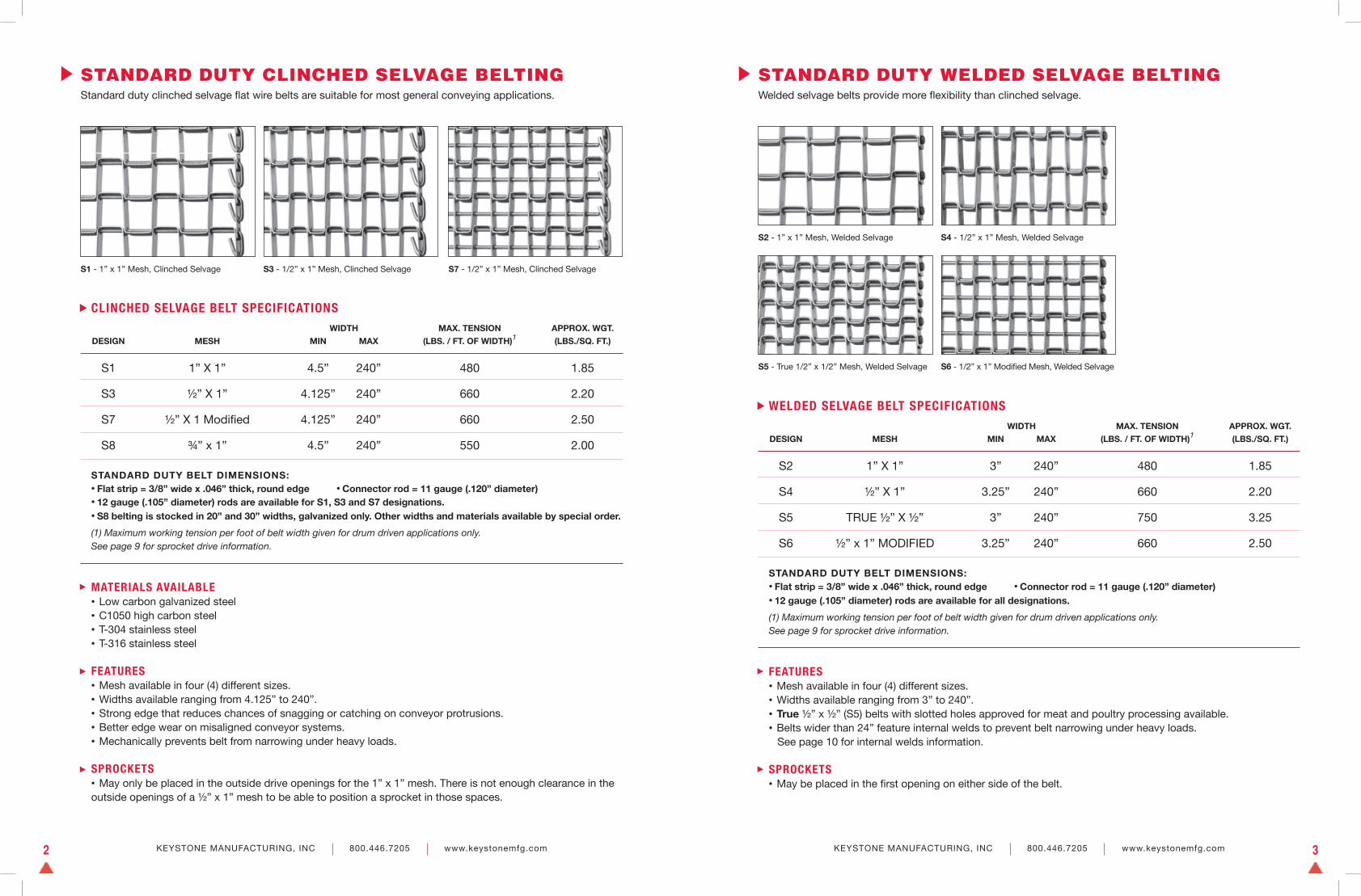
S1 1” X 1” 4.5” 240” 480 1.85
S3 ½” X 1” 4.125” 240” 660 2.20
S7 ½” X 1 Modifi ed 4.125” 240” 660 2.50
S8 ¾” x 1” 4.5” 240” 550 2.00
STANDARD DUTY CLINCHED SELVAGE BELTINGStandard duty clinched selvage fl at wire belts are suitable for most general conveying applications.
CLINCHED SELVAGE BELT SPECIFICATIONS
S1 - 1” x 1” Mesh, Clinched Selvage S3 - 1/2” x 1” Mesh, Clinched Selvage S7 - 1/2” x 1” Mesh, Clinched Selvage
STANDARD DUTY BELT DIMENSIONS:• Flat strip = 3/8” wide x .046” thick, round edge • Connector rod = 11 gauge (.120” diameter)• 12 gauge (.105” diameter) rods are available for S1, S3 and S7 designations.• S8 belting is stocked in 20” and 30” widths, galvanized only. Other widths and materials available by special order.
(1) Maximum working tension per foot of belt width given for drum driven applications only. See page 9 for sprocket drive information.
KEYSTONE MANUFACTURING, INC 800.446.7205 www.keystonemfg.com2
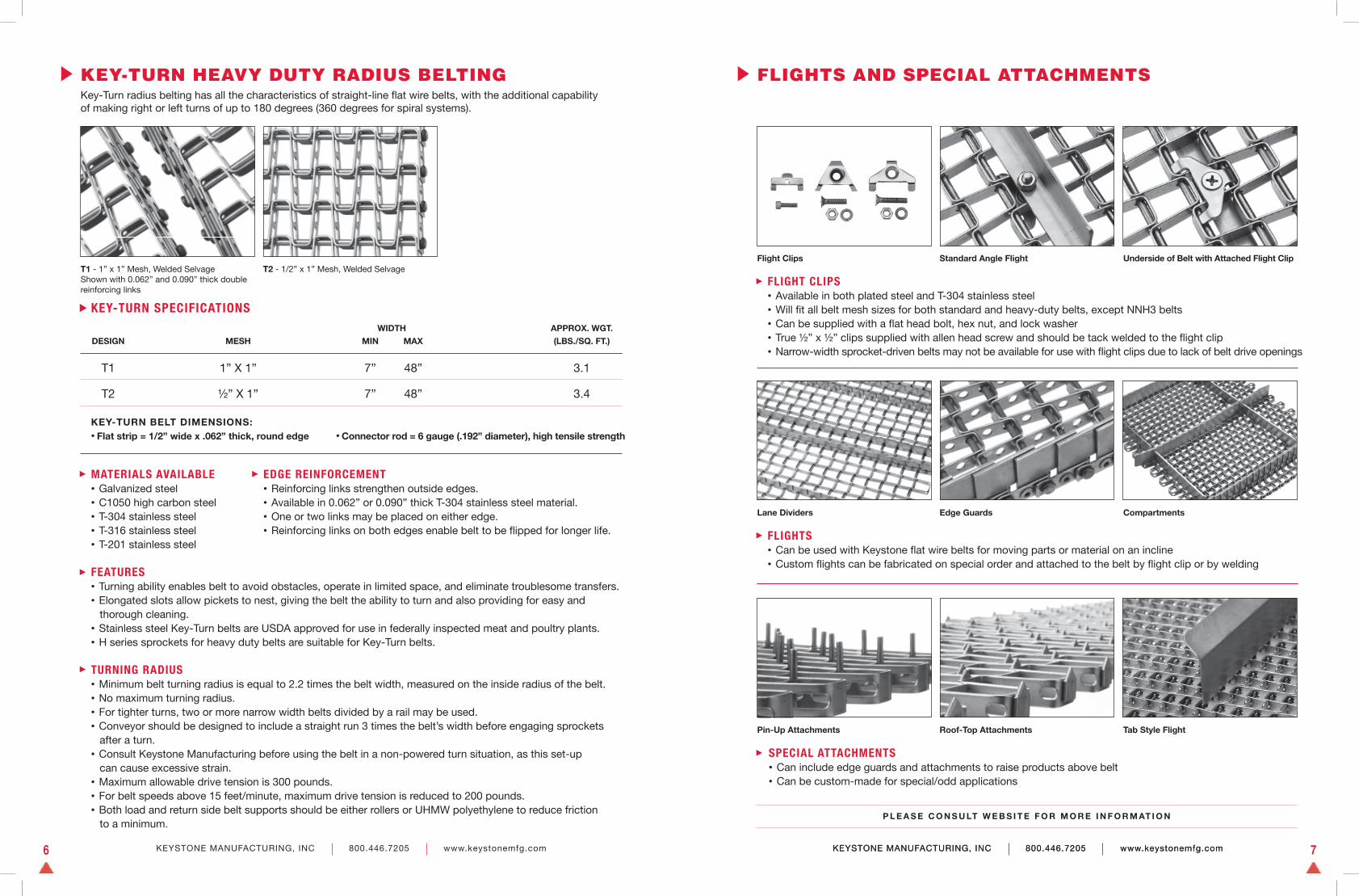
STANDARD DUTY WELDED SELVAGE BELTINGWelded selvage belts provide more fl exibility than clinched selvage.
KEYSTONE MANUFACTURING, INC 800.446.7205 www.keystonemfg.com 3
S2 - 1” x 1” Mesh, Welded Selvage S4 - 1/2” x 1” Mesh, Welded Selvage
S5 - True 1/2” x 1/2” Mesh, Welded Selvage S6 - 1/2” x 1” Modifi ed Mesh, Welded Selvage
FEATURES• Mesh available in four (4) different sizes.• Widths available ranging from 3” to 240”.• True ½” x ½” (S5) belts with slotted holes approved for meat and poultry processing available.• Belts wider than 24” feature internal welds to prevent belt narrowing under heavy loads. See page 10 for internal welds information. SPROCKETS• May be placed in the fi rst opening on either side of the belt.
WIDTH MAX. TENSION APPROX. WGT.
DESIGN MESH MIN MAX (LBS. / FT. OF WIDTH)1 (LBS./SQ. FT.)
S2 1” X 1” 3” 240” 480 1.85
S4 ½” X 1” 3.25” 240” 660 2.20
S5 TRUE ½” X ½” 3” 240” 750 3.25
S6 ½” x 1” MODIFIED 3.25” 240” 660 2.50
WELDED SELVAGE BELT SPECIFICATIONS
STANDARD DUTY BELT DIMENSIONS:• Flat strip = 3/8” wide x .046” thick, round edge • Connector rod = 11 gauge (.120” diameter)• 12 gauge (.105” diameter) rods are available for all designations.
(1) Maximum working tension per foot of belt width given for drum driven applications only. See page 9 for sprocket drive information.

MATERIALS AVAILABLE• Low carbon galvanized steel• C1050 high carbon steel• T-304 stainless steel• T-316 stainless steel• T-201 stainless steel
FEATURES• Mesh available in three (3) different sizes.• Widths available ranging from 3” to 192”.• Fabricated using a round edge fl at strip.• Belts wider than 24” are supplied with internal welds.• Belts 24” and under can be supplied with internal welds by request at no additional cost.
SPROCKETS• May be placed in the fi rst opening on either side of the belt.
WIDTH MAX. TENSION APPROX. WGT.
DESIGN MESH MIN MAX (LBS. / FT. OF WIDTH)1 (LBS./SQ. FT.)
H1 1” X 1” 3” 192” 1350 3.50
H2 ½” X 1” 4” 192” 1750 3.90
H3 ½” X 1 Modifi ed 6” 192” 1750 4.85
NNH3 ½” X 1 Modifi ed 6” 192” 2000 5.00
HEAVY DUTY WELDED SELVAGE BELTINGHeavy duty belts are approximately 2.5 times stronger than standard duty belts.
WELDED SELVAGE BELT SPECIFICATIONS
H1 - 1” x 1” Mesh, Welded Selvage H2 - 1/2” x 1” Mesh, Welded Selvage H3 - 1/2” x 1” Modifi ed Mesh, Welded Selvage
HEAVY DUTY BELT DIMENSIONS:• Flat strip = 1/2” wide x .062” thick, round edge • Connector rod = 6 gauge (.192” diameter), high tensile strength
(1) Maximum working tension per foot of belt width given for drum driven applications only. See page 9 for sprocket drive information.
KEYSTONE MANUFACTURING, INC 800.446.7205 www.keystonemfg.com4
FEATURES• Mesh available in two (2) different sizes.• Widths available ranging from 10” to 192”.• Mechanically prevents belt from narrowing under heavy loads.• Just as fl exible as welded selvage belts.
SPROCKETS• Cannot be placed in the fi rst drive opening on either edge of the belt at either mesh size.
SPECIAL BELTING• Keystone is able to produce fl at wire belts with special mesh sizes to meet the needs of unusual applications. Please consult the factory for more information.
WIDTH MAX. TENSION APPROX. WGT.
DESIGN MESH MIN MAX (LBS. / FT. OF WIDTH)1 (LBS./SQ. FT.)
H4 1” X 1” 10” 192” 1350 3.55
H5 ½” X 1” 10” 192” 1750 3.95
HEAVY DUTY CLINCHED SELVAGE BELTINGHeavy duty clinched selvage belts feature a better wearing edge surface for misaligned conveyor systems.
CLINCHED SELVAGE BELT SPECIFICATIONS
H4 - 1” x 1” Mesh, Clinched Selvage H5 - 1/2” x 1” Mesh, Clinched Selvage
HEAVY DUTY BELT DIMENSIONS:• Flat strip = 1/2” wide x .062” thick, round edge • Connector rod = 6 gauge (.192” diameter), high tensile strength
(1) Maximum working tension per foot of belt width given for drum driven applications only. See page 9 for sprocket drive information.
KEYSTONE MANUFACTURING, INC 800.446.7205 www.keystonemfg.com 5
Narrow Mesh Nut Harvester Belting Custom Filling Station Belt Belt with Custom Fixture
MATERIALS AVAILABLE• Galvanized steel• C1050 high carbon steel• T-304 stainless steel• T-316 stainless steel• T-201 stainless steel
FEATURES• Turning ability enables belt to avoid obstacles, operate in limited space, and eliminate troublesome transfers.• Elongated slots allow pickets to nest, giving the belt the ability to turn and also providing for easy and thorough cleaning.• Stainless steel Key-Turn belts are USDA approved for use in federally inspected meat and poultry plants.• H series sprockets for heavy duty belts are suitable for Key-Turn belts.
TURNING RADIUS• Minimum belt turning radius is equal to 2.2 times the belt width, measured on the inside radius of the belt.• No maximum turning radius.• For tighter turns, two or more narrow width belts divided by a rail may be used.• Conveyor should be designed to include a straight run 3 times the belt’s width before engaging sprockets after a turn.• Consult Keystone Manufacturing before using the belt in a non-powered turn situation, as this set-up can cause excessive strain.• Maximum allowable drive tension is 300 pounds.• For belt speeds above 15 feet/minute, maximum drive tension is reduced to 200 pounds.• Both load and return side belt supports should be either rollers or UHMW polyethylene to reduce friction to a minimum.
WIDTH APPROX. WGT.
DESIGN MESH MIN MAX (LBS./SQ. FT.)
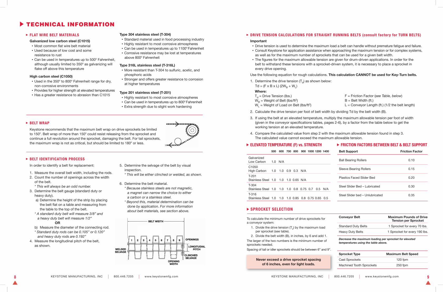
T1 1” X 1” 7” 48” 3.1
T2 ½” X 1” 7” 48” 3.4
KEY-TURN HEAVY DUTY RADIUS BELTINGKey-Turn radius belting has all the characteristics of straight-line fl at wire belts, with the additional capability of making right or left turns of up to 180 degrees (360 degrees for spiral systems).
KEY-TURN SPECIFICATIONS
T1 - 1” x 1” Mesh, Welded SelvageShown with 0.062” and 0.090” thick doublereinforcing links
T2 - 1/2” x 1” Mesh, Welded Selvage
KEY-TURN BELT DIMENSIONS:• Flat strip = 1/2” wide x .062” thick, round edge • Connector rod = 6 gauge (.192” diameter), high tensile strength
KEYSTONE MANUFACTURING, INC 800.446.7205 www.keystonemfg.com6 KEYSTONE MANUFACTURING, INC 800.446.7205 www.keystonemfg.com 7
EDGE REINFORCEMENT• Reinforcing links strengthen outside edges.• Available in 0.062” or 0.090” thick T-304 stainless steel material.• One or two links may be placed on either edge.• Reinforcing links on both edges enable belt to be fl ipped for longer life.
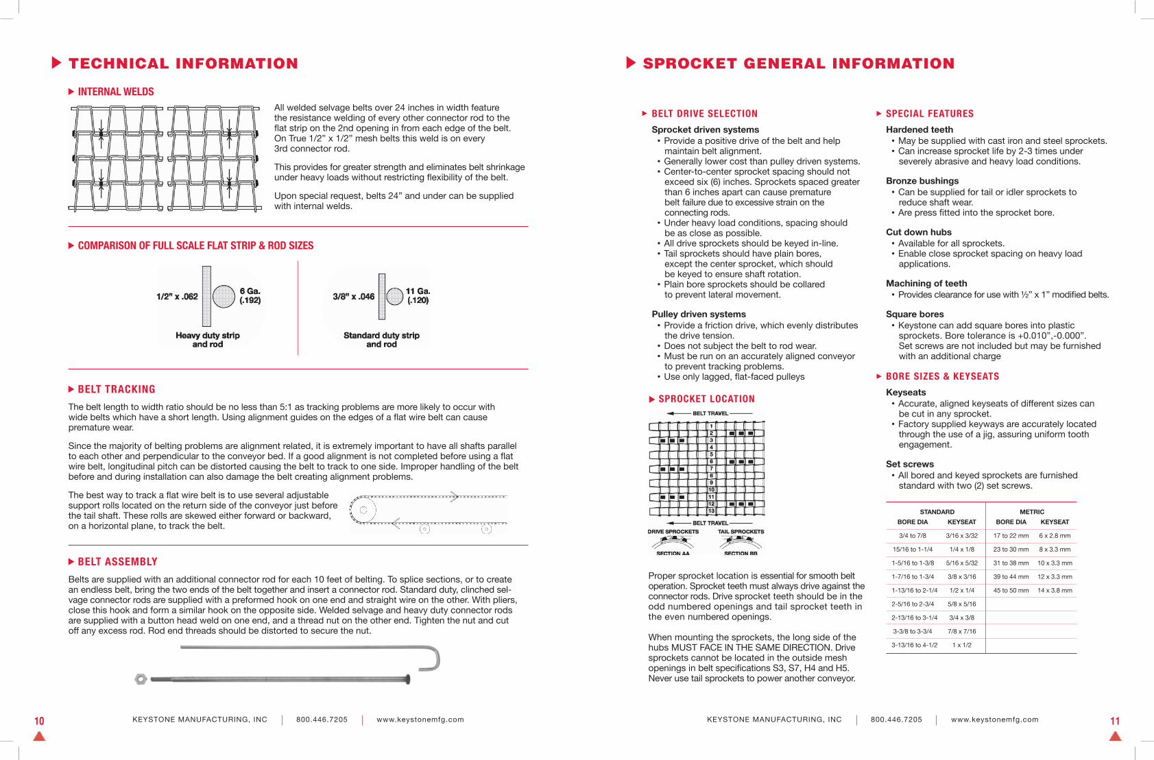
FLIGHTS AND SPECIAL ATTACHMENTS
KEYSTONE MANUFACTURING, INC 800.446.7205 www.keystonemfg.com
SPECIAL ATTACHMENTS• Can include edge guards and attachments to raise products above belt• Can be custom-made for special/odd applications
Lane Dividers Edge Guards
FLIGHTS• Can be used with Keystone fl at wire belts for moving parts or material on an incline• Custom fl ights can be fabricated on special order and attached to the belt by fl ight clip or by welding
Compartments
P L E A S E C O N S U LT W E B S I T E F O R M O R E I N F O R M AT I O N
Pin-Up Attachments Roof-Top Attachments Tab Style Flight
FLIGHT CLIPS• Available in both plated steel and T-304 stainless steel• Will fi t all belt mesh sizes for both standard and heavy-duty belts, except NNH3 belts• Can be supplied with a fl at head bolt, hex nut, and lock washer• True ½” x ½” clips supplied with allen head screw and should be tack welded to the fl ight clip• Narrow-width sprocket-driven belts may not be available for use with fl ight clips due to lack of belt drive openings
Flight Clips Standard Angle Flight Underside of Belt with Attached Flight Clip
KEYSTONE MANUFACTURING, INC 800.446.7205 www.keystonemfg.com8 KEYSTONE MANUFACTURING, INC 800.446.7205 www.keystonemfg.com 9
TECHNICAL INFORMATION
FLAT WIRE BELT MATERIALS
Galvanized low carbon steel (C1015) • Most common fl at wire belt material • Used because of low cost and some resistance to rust • Can be used in temperatures up to 500o Fahrenheit, although usually limited to 350o as galvanizing will fl ake off above this temperature
High carbon steel (C1050) • Used in the 350o to 800o Fahrenheit range for dry, non-corrosive environments • Provides for higher strength at elevated temperatures • Has a greater resistance to abrasion than C1015
Type 304 stainless steel (T-304) • Standard material used in food processing industry • Highly resistant to most corrosive atmospheres • Can be used in temperatures up to 1100o Fahrenheit • Corrosive resistance may be lost at temperatures above 800o Fahrenheit
Type 316L stainless steel (T-316L) • More resistant than T-304 to sulfuric, acetic, and phosphoric acids • Stronger and offers greater resistance to corrosion at higher temperatures
Type 201 stainless steel (T-201) • Highly resistant to most corrosive atmospheres • Can be used in temperatures up to 800o Fahrenheit • Extra strength due to slight work hardening
BELT IDENTIFICATION PROCESS
In order to identify a belt for replacement:
1. Measure the overall belt width, including the rods.2. Count the number of openings across the width of the belt. * This will always be an odd number.3. Determine the belt gauge (standard duty or heavy duty). a) Determine the height of the strip by placing the belt fl at on a table and measuring from the table to the top of the belt. * A standard duty belt will measure 3/8” and a heavy duty belt will measure 1/2” OR b) Measure the diameter of the connecting rod. * Standard duty rods can be 0.105” or 0.120” and heavy duty rods are 0.192”4. Measure the longitudinal pitch of the belt, as shown.
5. Determine the selvage of the belt by visual inspection. * This will be either clinched or welded, as shown.
6. Determine the belt material. * Because stainless steels are not magnetic, a magnet can narrow the choice to either a carbon or a stainless steel. * Beyond this, material determination can be done by application. For more information about belt materials, see section above.
DRIVE TENSION CALCULATIONS FOR STRAIGHT RUNNING BELTS (consult factory for TURN BELTS)
Important • Drive tension is used to determine the maximum load a belt can handle without premature fatigue and failure. • Consult Keystone for application assistance when approaching the maximum tension or for complex systems, as well as for the maximum number of sprockets that can be used for a given belt width. • The fi gures for the maximum allowable tension are given for drum-driven applications. In order for the belt to withstand these tensions with a sprocket-driven system, it is necessary to place a sprocket in every drive opening.
Use the following equation for rough calculations. This calculation CANNOT be used for Key-Turn belts.
1. Determine the drive tension (Td) as shown below: Td = (F x B x L) (2WB + WL)
Where: Td = Drive Tension (lbs.) WB = Weight of Belt (lbs/ft2) WL = Weight of Load on Belt (lbs/ft2)
F = Friction Factor (see Table, below) B = Belt Width (ft.) L = Conveyor Length (ft.) (1/2 the belt length)
2. Calculate the drive tension per foot of belt width by dividing Td by the belt width (B).
3. If using the belt at an elevated temperature, multiply the maximum allowable tension per foot of width (given in the conveyor specifi cations tables, pages 2-6), by a factor from the table below to get the working tension at an elevated temperature.
4. Compare the calculated value from step 2 with the maximum allowable tension found in step 3. The calculated value cannot exceed the maximum allowable tension.
500 600 700 800 900 1000 1200 1400
Galvanized Low Carbon 1.0 N/A
C1050 High Carbon 1.0 1.0 0.9 0.3 N/A
T-201Stainless Steel 1.0 1.0 1.0 0.65 N/A
T-304Stainless Steel 1.0 1.0 1.0 0.8 0.75 0.7 0.5 N/A
T-316Stainless Steel 1.0 1.0 1.0 0.85 0.8 0.75 0.65 0.5
ELEVATED TEMPERATURE (F) vs. STRENGTH
Belt Support Friction Factor
Ball Bearing Rollers 0.10
Sleeve Bearing Rollers 0.15
Plastics Faced Slider Bed 0.20
Steel Slider Bed – Lubricated 0.30
Steel Slider bed – Unlubricated 0.35
FRICTION FACTORS BETWEEN BELT & BELT SUPPORT
SPROCKET SELECTION
To calculate the minimum number of drive sprockets for a conveyor system:
1. Divide the drive tension (Td) by the maximum load per sprocket (see table). 2. Divide the belt width (B), in inches, by 6 and add 1.
The larger of the two numbers is the minimum number ofsprockets needed.
Spacing of tail or idler sprockets should be between 6” and 9”.Sprocket Type Maximum Belt Speed
Cast Sprockets 120 fpm
Machined Tooth Sprockets 250 fpm
Never exceed a drive sprocket spacing of 6 inches, even for light loads.
BELT WRAP
Keystone recommends that the maximum belt wrap on drive sprockets be limited to 150o. Belt wrap of more than 150o could resist releasing from the sprocket and continue a full revolution around the sprocket, damaging the belt. For tail sprockets, the maximum wrap is not as critical, but should be limited to 180o or less.
Conveyor Belt Maximum Pounds of Drive Tension per Sprocket
Standard Duty Belts 1 Sprocket for every 70 lbs.
Heavy Duty Belts 1 Sprocket for every 190 lbs.
Decrease the maximum loading per sprocket for elevatedtemperatures using the table above.
KEYSTONE MANUFACTURING, INC 800.446.7205 www.keystonemfg.com 11KEYSTONE MANUFACTURING, INC 800.446.7205 www.keystonemfg.com10
SPROCKET GENERAL INFORMATION
BELT DRIVE SELECTION
Sprocket driven systems • Provide a positive drive of the belt and help maintain belt alignment. • Generally lower cost than pulley driven systems. • Center-to-center sprocket spacing should not exceed six (6) inches. Sprockets spaced greater than 6 inches apart can cause premature belt failure due to excessive strain on the connecting rods. • Under heavy load conditions, spacing should be as close as possible. • All drive sprockets should be keyed in-line. • Tail sprockets should have plain bores, except the center sprocket, which should be keyed to ensure shaft rotation. • Plain bore sprockets should be collared to prevent lateral movement.
Pulley driven systems • Provide a friction drive, which evenly distributes the drive tension. • Does not subject the belt to rod wear. • Must be run on an accurately aligned conveyor to prevent tracking problems. • Use only lagged, fl at-faced pulleys
SPECIAL FEATURES
Hardened teeth • May be supplied with cast iron and steel sprockets. • Can increase sprocket life by 2-3 times under severely abrasive and heavy load conditions.
Bronze bushings • Can be supplied for tail or idler sprockets to reduce shaft wear. • Are press fi tted into the sprocket bore.
Cut down hubs • Available for all sprockets. • Enable close sprocket spacing on heavy load applications.
Machining of teeth • Provides clearance for use with ½” x 1” modifi ed belts.
Square bores • Keystone can add square bores into plastic sprockets. Bore tolerance is +0.010”,-0.000”. Set screws are not included but may be furnished with an additional charge
BORE SIZES & KEYSEATS
Keyseats • Accurate, aligned keyseats of different sizes can be cut in any sprocket. • Factory supplied keyways are accurately located through the use of a jig, assuring uniform tooth engagement.
Set screws • All bored and keyed sprockets are furnished standard with two (2) set screws.
TECHNICAL INFORMATION
BELT TRACKING
The belt length to width ratio should be no less than 5:1 as tracking problems are more likely to occur with wide belts which have a short length. Using alignment guides on the edges of a fl at wire belt can cause premature wear.
Since the majority of belting problems are alignment related, it is extremely important to have all shafts parallel to each other and perpendicular to the conveyor bed. If a good alignment is not completed before using a fl at wire belt, longitudinal pitch can be distorted causing the belt to track to one side. Improper handling of the belt before and during installation can also damage the belt creating alignment problems.
The best way to track a fl at wire belt is to use several adjustable support rolls located on the return side of the conveyor just before the tail shaft. These rolls are skewed either forward or backward, on a horizontal plane, to track the belt.
BELT ASSEMBLY
Belts are supplied with an additional connector rod for each 10 feet of belting. To splice sections, or to create an endless belt, bring the two ends of the belt together and insert a connector rod. Standard duty, clinched sel-vage connector rods are supplied with a preformed hook on one end and straight wire on the other. With pliers, close this hook and form a similar hook on the opposite side. Welded selvage and heavy duty connector rods are supplied with a button head weld on one end, and a thread nut on the other end. Tighten the nut and cut off any excess rod. Rod end threads should be distorted to secure the nut.
COMPARISON OF FULL SCALE FLAT STRIP & ROD SIZES
SPROCKET LOCATION
Proper sprocket location is essential for smooth belt operation. Sprocket teeth must always drive against the connector rods. Drive sprocket teeth should be in the odd numbered openings and tail sprocket teeth in the even numbered openings.
When mounting the sprockets, the long side of the hubs MUST FACE IN THE SAME DIRECTION. Drive sprockets cannot be located in the outside mesh openings in belt specifi cations S3, S7, H4 and H5. Never use tail sprockets to power another conveyor.
STANDARD METRIC
BORE DIA KEYSEAT BORE DIA KEYSEAT
3/4 to 7/8 3/16 x 3/32 17 to 22 mm 6 x 2.8 mm
15/16 to 1-1/4 1/4 x 1/8 23 to 30 mm 8 x 3.3 mm
1-5/16 to 1-3/8 5/16 x 5/32 31 to 38 mm 10 x 3.3 mm
1-7/16 to 1-3/4 3/8 x 3/16 39 to 44 mm 12 x 3.3 mm
1-13/16 to 2-1/4 1/2 x 1/4 45 to 50 mm 14 x 3.8 mm
2-5/16 to 2-3/4 5/8 x 5/16
2-13/16 to 3-1/4 3/4 x 3/8
3-3/8 to 3-3/4 7/8 x 7/16
3-13/16 to 4-1/2 1 x 1/2
INTERNAL WELDSAll welded selvage belts over 24 inches in width feature the resistance welding of every other connector rod to the fl at strip on the 2nd opening in from each edge of the belt. On True 1/2” x 1/2” mesh belts this weld is on every 3rd connector rod.
This provides for greater strength and eliminates belt shrinkage under heavy loads without restricting fl exibility of the belt.
Upon special request, belts 24” and under can be supplied with internal welds.
KEYSTONE MANUFACTURING, INC 800.446.7205 www.keystonemfg.com12 KEYSTONE MANUFACTURING, INC 800.446.7205 www.keystonemfg.com 13
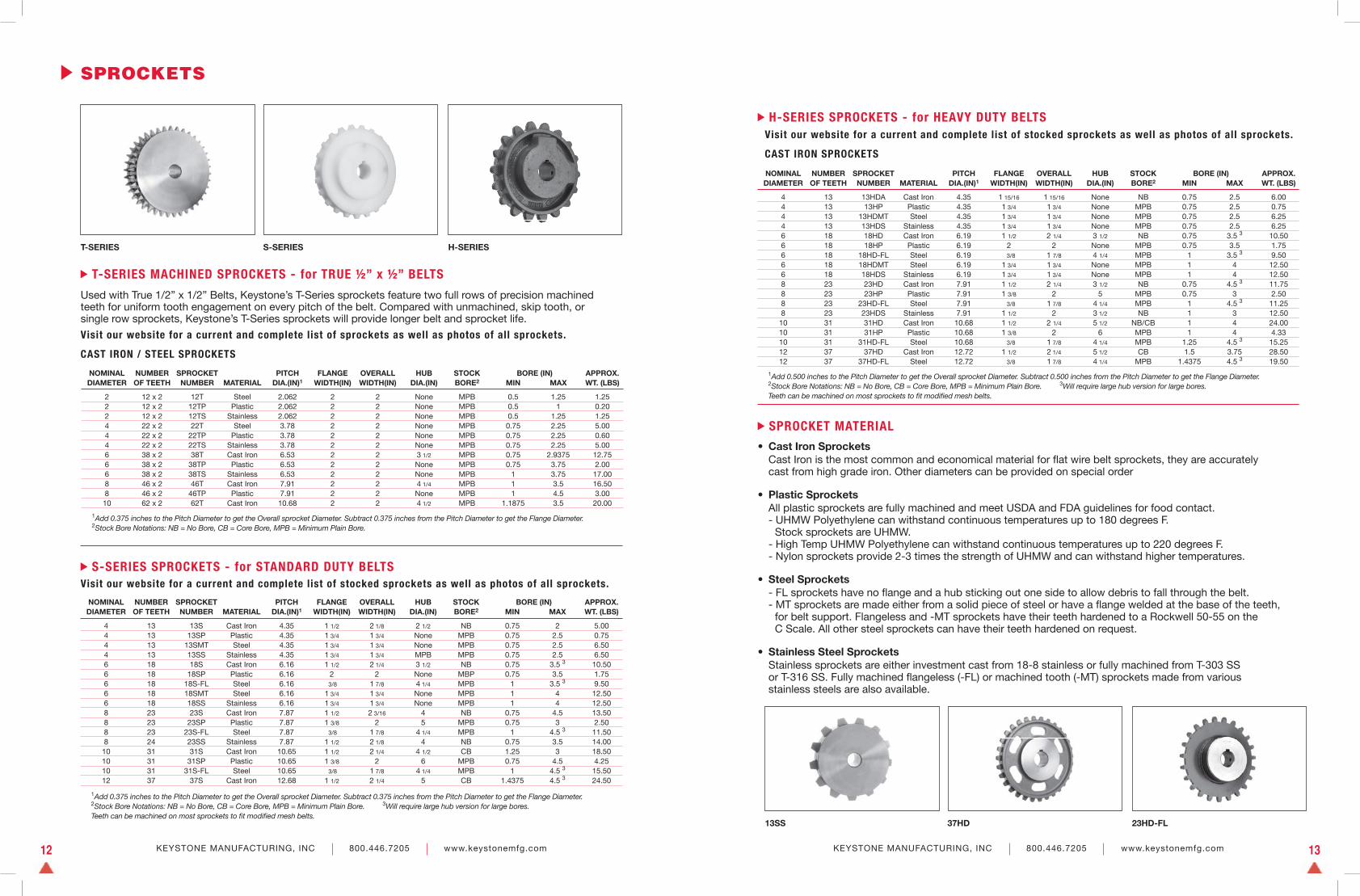
SPROCKETS
NOMINAL NUMBER SPROCKET PITCH FLANGE OVERALL HUB STOCK BORE (IN) APPROX. DIAMETER OF TEETH NUMBER MATERIAL DIA.(IN)1 WIDTH(IN) WIDTH(IN) DIA.(IN) BORE2 MIN MAX WT. (LBS)
4 13 13HDA Cast Iron 4.35 1 15/16 1 15/16 None NB 0.75 2.5 6.00 4 13 13HP Plastic 4.35 1 3/4 1 3/4 None MPB 0.75 2.5 0.75 4 13 13HDMT Steel 4.35 1 3/4 1 3/4 None MPB 0.75 2.5 6.25 4 13 13HDS Stainless 4.35 1 3/4 1 3/4 None MPB 0.75 2.5 6.25 6 18 18HD Cast Iron 6.19 1 1/2 2 1/4 3 1/2 NB 0.75 3.5 3 10.50 6 18 18HP Plastic 6.19 2 2 None MPB 0.75 3.5 1.75 6 18 18HD-FL Steel 6.19 3/8 1 7/8 4 1/4 MPB 1 3.5 3 9.50 6 18 18HDMT Steel 6.19 1 3/4 1 3/4 None MPB 1 4 12.50 6 18 18HDS Stainless 6.19 1 3/4 1 3/4 None MPB 1 4 12.50 8 23 23HD Cast Iron 7.91 1 1/2 2 1/4 3 1/2 NB 0.75 4.5 3 11.75 8 23 23HP Plastic 7.91 1 3/8 2 5 MPB 0.75 3 2.50 8 23 23HD-FL Steel 7.91 3/8 1 7/8 4 1/4 MPB 1 4.5 3 11.25 8 23 23HDS Stainless 7.91 1 1/2 2 3 1/2 NB 1 3 12.50 10 31 31HD Cast Iron 10.68 1 1/2 2 1/4 5 1/2 NB/CB 1 4 24.00 10 31 31HP Plastic 10.68 1 3/8 2 6 MPB 1 4 4.33 10 31 31HD-FL Steel 10.68 3/8 1 7/8 4 1/4 MPB 1.25 4.5 3 15.25 12 37 37HD Cast Iron 12.72 1 1/2 2 1/4 5 1/2 CB 1.5 3.75 28.50 12 37 37HD-FL Steel 12.72 3/8 1 7/8 4 1/4 MPB 1.4375 4.5 3 19.50
H-SERIES SPROCKETS - for HEAVY DUTY BELTS
1Add 0.500 inches to the Pitch Diameter to get the Overall sprocket Diameter. Subtract 0.500 inches from the Pitch Diameter to get the Flange Diameter. 2Stock Bore Notations: NB = No Bore, CB = Core Bore, MPB = Minimum Plain Bore. 3Will require large hub version for large bores. Teeth can be machined on most sprockets to fi t modifi ed mesh belts.
• Cast Iron Sprockets Cast Iron is the most common and economical material for fl at wire belt sprockets, they are accurately cast from high grade iron. Other diameters can be provided on special order
• Plastic Sprockets All plastic sprockets are fully machined and meet USDA and FDA guidelines for food contact. - UHMW Polyethylene can withstand continuous temperatures up to 180 degrees F. Stock sprockets are UHMW. - High Temp UHMW Polyethylene can withstand continuous temperatures up to 220 degrees F. - Nylon sprockets provide 2-3 times the strength of UHMW and can withstand higher temperatures.
• Steel Sprockets - FL sprockets have no fl ange and a hub sticking out one side to allow debris to fall through the belt. - MT sprockets are made either from a solid piece of steel or have a fl ange welded at the base of the teeth, for belt support. Flangeless and -MT sprockets have their teeth hardened to a Rockwell 50-55 on the C Scale. All other steel sprockets can have their teeth hardened on request. • Stainless Steel Sprockets Stainless sprockets are either investment cast from 18-8 stainless or fully machined from T-303 SS or T-316 SS. Fully machined fl angeless (-FL) or machined tooth (-MT) sprockets made from various stainless steels are also available.
SPROCKET MATERIAL
Visit our website for a current and complete list of stocked sprockets as well as photos of all sprockets.
CAST IRON SPROCKETS
T-SERIES MACHINED SPROCKETS - for TRUE ½” x ½” BELTS
Used with True 1/2” x 1/2” Belts, Keystone’s T-Series sprockets feature two full rows of precision machined teeth for uniform tooth engagement on every pitch of the belt. Compared with unmachined, skip tooth, or single row sprockets, Keystone’s T-Series sprockets will provide longer belt and sprocket life.
Visit our website for a current and complete list of sprockets as well as photos of all sprockets.
CAST IRON / STEEL SPROCKETS
NOMINAL NUMBER SPROCKET PITCH FLANGE OVERALL HUB STOCK BORE (IN) APPROX. DIAMETER OF TEETH NUMBER MATERIAL DIA.(IN)1 WIDTH(IN) WIDTH(IN) DIA.(IN) BORE2 MIN MAX WT. (LBS)
4 13 13S Cast Iron 4.35 1 1/2 2 1/8 2 1/2 NB 0.75 2 5.00 4 13 13SP Plastic 4.35 1 3/4 1 3/4 None MPB 0.75 2.5 0.75 4 13 13SMT Steel 4.35 1 3/4 1 3/4 None MPB 0.75 2.5 6.50 4 13 13SS Stainless 4.35 1 3/4 1 3/4 MPB MPB 0.75 2.5 6.50 6 18 18S Cast Iron 6.16 1 1/2 2 1/4 3 1/2 NB 0.75 3.5 3 10.50 6 18 18SP Plastic 6.16 2 2 None MBP 0.75 3.5 1.75 6 18 18S-FL Steel 6.16 3/8 1 7/8 4 1/4 MPB 1 3.5 3 9.50 6 18 18SMT Steel 6.16 1 3/4 1 3/4 None MPB 1 4 12.50 6 18 18SS Stainless 6.16 1 3/4 1 3/4 None MPB 1 4 12.50 8 23 23S Cast Iron 7.87 1 1/2 2 3/16 4 NB 0.75 4.5 13.50 8 23 23SP Plastic 7.87 1 3/8 2 5 MPB 0.75 3 2.50 8 23 23S-FL Steel 7.87 3/8 1 7/8 4 1/4 MPB 1 4.5 3 11.50 8 24 23SS Stainless 7.87 1 1/2 2 1/8 4 NB 0.75 3.5 14.00 10 31 31S Cast Iron 10.65 1 1/2 2 1/4 4 1/2 CB 1.25 3 18.50 10 31 31SP Plastic 10.65 1 3/8 2 6 MPB 0.75 4.5 4.25 10 31 31S-FL Steel 10.65 3/8 1 7/8 4 1/4 MPB 1 4.5 3 15.50 12 37 37S Cast Iron 12.68 1 1/2 2 1/4 5 CB 1.4375 4.5 3 24.50
1Add 0.375 inches to the Pitch Diameter to get the Overall sprocket Diameter. Subtract 0.375 inches from the Pitch Diameter to get the Flange Diameter. 2Stock Bore Notations: NB = No Bore, CB = Core Bore, MPB = Minimum Plain Bore. 3Will require large hub version for large bores. Teeth can be machined on most sprockets to fi t modifi ed mesh belts.
NOMINAL NUMBER SPROCKET PITCH FLANGE OVERALL HUB STOCK BORE (IN) APPROX. DIAMETER OF TEETH NUMBER MATERIAL DIA.(IN)1 WIDTH(IN) WIDTH(IN) DIA.(IN) BORE2 MIN MAX WT. (LBS)
2 12 x 2 12T Steel 2.062 2 2 None MPB 0.5 1.25 1.25 2 12 x 2 12TP Plastic 2.062 2 2 None MPB 0.5 1 0.20 2 12 x 2 12TS Stainless 2.062 2 2 None MPB 0.5 1.25 1.25 4 22 x 2 22T Steel 3.78 2 2 None MPB 0.75 2.25 5.00 4 22 x 2 22TP Plastic 3.78 2 2 None MPB 0.75 2.25 0.60 4 22 x 2 22TS Stainless 3.78 2 2 None MPB 0.75 2.25 5.00 6 38 x 2 38T Cast Iron 6.53 2 2 3 1/2 MPB 0.75 2.9375 12.75 6 38 x 2 38TP Plastic 6.53 2 2 None MPB 0.75 3.75 2.00 6 38 x 2 38TS Stainless 6.53 2 2 None MPB 1 3.75 17.00 8 46 x 2 46T Cast Iron 7.91 2 2 4 1/4 MPB 1 3.5 16.50 8 46 x 2 46TP Plastic 7.91 2 2 None MPB 1 4.5 3.00 10 62 x 2 62T Cast Iron 10.68 2 2 4 1/2 MPB 1.1875 3.5 20.00
1Add 0.375 inches to the Pitch Diameter to get the Overall sprocket Diameter. Subtract 0.375 inches from the Pitch Diameter to get the Flange Diameter. 2Stock Bore Notations: NB = No Bore, CB = Core Bore, MPB = Minimum Plain Bore.
S-SERIES SPROCKETS - for STANDARD DUTY BELTSVisit our website for a current and complete list of stocked sprockets as well as photos of all sprockets.
T-SERIES S-SERIES H-SERIES
13SS 37HD 23HD-FL
KEYSTONE MANUFACTURING, INC 800.446.7205 www.keystonemfg.com 15KEYSTONE MANUFACTURING, INC 800.446.7205 www.keystonemfg.com14
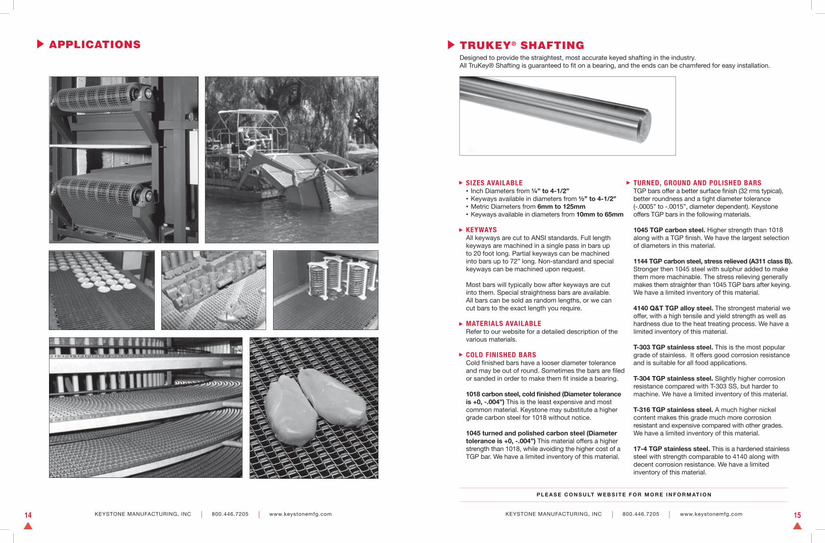
TRUKEY® SHAFTINGDesigned to provide the straightest, most accurate keyed shafting in the industry. All TruKey® Shafting is guaranteed to fi t on a bearing, and the ends can be chamfered for easy installation.
SIZES AVAILABLE• Inch Diameters from ¼” to 4-1/2”• Keyways available in diameters from ½” to 4-1/2”• Metric Diameters from 6mm to 125mm • Keyways available in diameters from 10mm to 65mm
KEYWAYSAll keyways are cut to ANSI standards. Full length keyways are machined in a single pass in bars up to 20 foot long. Partial keyways can be machined into bars up to 72” long. Non-standard and special keyways can be machined upon request.
Most bars will typically bow after keyways are cut into them. Special straightness bars are available. All bars can be sold as random lengths, or we can cut bars to the exact length you require.
MATERIALS AVAILABLERefer to our website for a detailed description of the various materials.
COLD FINISHED BARSCold fi nished bars have a looser diameter tolerance and may be out of round. Sometimes the bars are fi led or sanded in order to make them fi t inside a bearing.
1018 carbon steel, cold fi nished (Diameter tolerance is +0, -.004”) This is the least expensive and most common material. Keystone may substitute a higher grade carbon steel for 1018 without notice.
1045 turned and polished carbon steel (Diameter tolerance is +0, -.004”) This material offers a higher strength than 1018, while avoiding the higher cost of a TGP bar. We have a limited inventory of this material.
TURNED, GROUND AND POLISHED BARSTGP bars offer a better surface fi nish (32 rms typical), better roundness and a tight diameter tolerance (-.0005” to -.0015”, diameter dependent). Keystone offers TGP bars in the following materials.
1045 TGP carbon steel. Higher strength than 1018 along with a TGP fi nish. We have the largest selection of diameters in this material.
1144 TGP carbon steel, stress relieved (A311 class B). Stronger then 1045 steel with sulphur added to make them more machinable. The stress relieving generally makes them straighter than 1045 TGP bars after keying. We have a limited inventory of this material.
4140 Q&T TGP alloy steel. The strongest material we offer, with a high tensile and yield strength as well as hardness due to the heat treating process. We have a limited inventory of this material.
T-303 TGP stainless steel. This is the most popular grade of stainless. It offers good corrosion resistance and is suitable for all food applications.
T-304 TGP stainless steel. Slightly higher corrosion resistance compared with T-303 SS, but harder to machine. We have a limited inventory of this material.
T-316 TGP stainless steel. A much higher nickel content makes this grade much more corrosion resistant and expensive compared with other grades. We have a limited inventory of this material.
17-4 TGP stainless steel. This is a hardened stainless steel with strength comparable to 4140 along with decent corrosion resistance. We have a limited inventory of this material.
P L E A S E C O N S U LT W E B S I T E F O R M O R E I N F O R M AT I O N
APPLICATIONS

www.keystonemfg.com
KEYSTONE MANUFACTURING, INC. B E L T I N G . S P R O C K E T S . S H A F T I N G
P.O. Box 270 668 Cleveland Street Rochester, PA 15074-0270 TEL 800.446.7205 FAX 724.775.2739 [email protected]
5M 12.10
We accept all major credit cards.