polimax - seekpartfile.seekpart.com/keywordpdf/2010/12/2/201012212208453.pdf · for use where gate...
TRANSCRIPT

D-M-E Hot Sprue Bushings
Polimax®
A wide range of high-performance
hot sprue bushings

U.S. 800-626-6653 n Canada 800-387-6600 n www.dme.net
2
Polimax® Hot Sprue BushingsPlaStic materialS and SPecificationS
Plastic Material Process conditions
MATERIAL STANDARD RESIN SYMBOL
PROCESS TEMPERATURE
MOLD TEMPERATURE
HOT RUNNER TEMPERATURE
DENSITY MELTING
SOLID DENSITY
[°C] [°F] [°C] [°F] [°C] [°F] [g/cm3] [Ibs/inch3] [g/cm3] [Ibs/inch3]
Styrene Butadiene SB 210 410 70 158 230 446 0.93 0.0366 1.02 0.0369
Polyurethane PUR 220 428 45 113 240 464 0.93 0.0366 1.11 0.0401
Polyvinyl chloride PVC/Flex 175 347 35 95 200 392 1.02 0.0405 1.38 0.0499
Styrene-acrylonitrile SAN 230 446 80 176 255 491 0.99 0.0358 1.08 0.0390
Polystyrene PS 210 410 45 113 230 446 0.95 0.0343 1.05 0.0379
Polycarbonate PC 300 572 80 176 330 626 1.08 0.0390 1.20 0.0434
Polyphenylene Oxide-Styrene PPO 260 500 80 176 300 572 0.99 0.0358 1.13 0.0408
Polyethylene Pe 200 392 25 77 225 437 0.74 0.0267 0.96 0.0347
Polypropylene PP 225 437 40 104 245 473 0.73 0.0264 0.91 0.0329
Polyether-etherketone PeeK 330 626 165 329 370 698 1.13 0.0408 1.37 0.0495
Polyphenylene Sulfide PPS 300 572 110 230 330 626 1.53 0.0553 1.70 0.0614
Polyebutylene Terephthalate PBT 265 509 60 140 290 554 1.44 0.0520 1.57 0.0567
Polyamide 6 PA 6 220 428 90 194 250 482 0.98 0.0354 1.14 0.0412
Polyamide 66 PA 66 255 491 90 194 280 536 1.09 0.0394 1.26 0.0455
Thermal Plastic elastomers TPe 240 464 35 95 265 509 0.78 0.0282 0.90 0.0325
Polyoxymethylene (Polyacetal) POM 180 356 100 212 200 392 1.16 0.0419 1.42 0.0513
Polymethyl Methacrylate PMMA 235 455 70 158 250 482 1.09 0.0394 1.18 0.0426
Acrylonitrile Butadiene Styrene ABS 225 437 70 158 250 482 0.95 0.0343 1.08 0.0390
Plastic Material Flow indeX
HIGH MFI MEDIUM MFI LOw MFI
SB ABS PVC/Flex
PS SAN PA 6 PC
Pe PPO PA 66 TPe PBT
PP PPS POM PeeK PUR
PeT PMMA
NOTE: Temperature and density values shown above are general, and may not apply to your application. Please refer to proper processing data for the resin grade intended for your specific application. Failure to use temperature settings appropriate to the specific resin and resin grade intended for your application may result in poor part quality, or inability to produce acceptable molded parts.
Polimax is a registered trade mark of
•Large number of bushing and tip combinations
•Two flow channel sizes
•Lengths up to 185mm
•High performance capability
•Standard & wear-resistant tips
•Precise thermal control
U.S. 800-626-6653 n Canada 800-387-6600 n www.dme.net
3
Polimax® Hot Sprue BushingsBUSHinG Selection
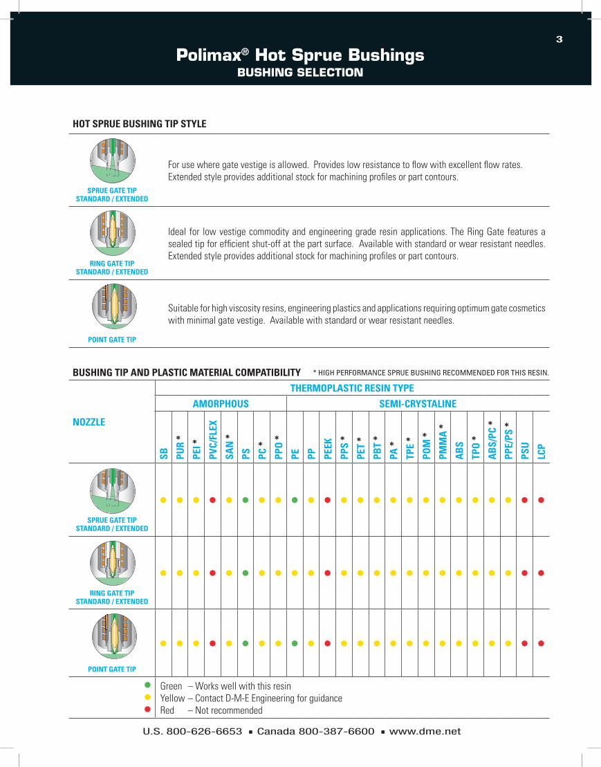
HOT SPRUE BUSHING TIP STYLE
SPRUE GATE TIP STANDARD / ExTENDED
For use where gate vestige is allowed. Provides low resistance to flow with excellent flow rates. Extended style provides additional stock for machining profiles or part contours.
RING GATE TIP STANDARD / ExTENDED
Ideal for low vestige commodity and engineering grade resin applications. The Ring Gate features a sealed tip for efficient shut-off at the part surface. Available with standard or wear resistant needles. Extended style provides additional stock for machining profiles or part contours.
POINT GATE TIP
Suitable for high viscosity resins, engineering plastics and applications requiring optimum gate cosmetics with minimal gate vestige. Available with standard or wear resistant needles.
BUSHING TIP AND PLASTIC MATERIAL COMPATIBILITY
NOzzLE
THERMOPLASTIC RESIN TYPE
AMORPHOUS SEMI-CRYSTALINE
SB
PUR
*
PEI *
PVC/
FLEx
SAN
*
PS PC *
PPO
*
PE PP PEEk
PPS
*
PET
*
PBT
*
PA *
TPE
*
POM
*
PMM
A *
AB
S
TPO
*
AB
S/PC
*
PPE/
PS *
PSU
LCP
SPRUE GATE TIP STANDARD / ExTENDED
l l l l l l l l l l l l l l l l l l l l l l l l
RING GATE TIP STANDARD / ExTENDED
l l l l l l l l l l l l l l l l l l l l l l l l
POINT GATE TIP
l l l l l l l l l l l l l l l l l l l l l l l l
lll
GreenYellowRed
– Works well with this resin– Contact D-M-E Engineering for guidance– Not recommended
* HigH PeRFORMANCe SPRUe BUSHiNg ReCOMMeNded FOR THiS ReSiN.

U.S. 800-626-6653 n Canada 800-387-6600 n www.dme.net
4
Polimax® Hot Sprue BushingsmaximUm flow caPacity taBleS
0
10
20
40
60
80
100
200
300
400
500
700
900
1500
3000
5000
1.0 1.3 8.07.06.05.04.03.02.52.01.81.5
DEFINITION OF MATERIAL INPUTThe optimal gate diameter will vary according to the resin, Melt Flow Index and part weight.Please refer to the table for guidelines. Other factors to consider when defining gate requirements for a D-M-E Polimax System are:
• Product geometry
• Polymer type
• Mold and injection machine conditions
Part
wei
ght (
gr)
Gate Diameter (mm)
High MFI
Medium MFI
Low MFI
MAxIMUM BUSHING FLOw CAPACITY
MAxIMUM LOAD wEIGHT IN GRAMS wITH MAxIMUM HOLE DIAMETERS
NOzzLE 200 SERIES 500 SERIES 800 SERIES MFI (Melt Flow Index)
SPRUE GATE TIP STANDARD / ExTENDED
800 1400 2000 HigH
400 700 1000 MediUM
200 300 450 lOW
RING GATE TIP STANDARD / ExTENDED
210 980 1400 HigH
105 490 700 MediUM
52 210 315 lOW
POINT GATE TIP
210 980 1400 HigH
105 490 700 MediUM
52 210 315 lOW

U.S. 800-626-6653 n Canada 800-387-6600 n www.dme.net
5
Polimax High Performance Hot Sprue BushingsSerieS 200
BUSHING BODY HEATER CABLE EXIT
RBP
COOLING LINES
CEP
TMP
RCP
POINT GATE TIP
"R" - "D"
GATING DETAIL
GATING DETAIL
LOCATION RING (SEE PAGE 13)
View A
View B
CAVITY BLOCK VIEW A
or " A" = A x 0.0000064 x (Setpoint °F - 68°F)Bushing Thermal Expansion " A" = A x 0.0000115 x (Setpoint °C - 20°C)
+0.000+0.025
8.0 (min.)
120.0(min.)
AØ0.02
2x45
°16
.5
Ø40.000
R1
R0.4 (max.)
30°
R3Ø 19.1
3.0
1x45
°
+0.2+0.3
18.0
8.5
Ø 34.0Ø 38.1
Ø 8.0
4.0
Ø 1.0 (min.)Ø 2.6 (max.)
-A-
0.5x
45°
90°
GATEØ
"B"
0.15
0.50
(tan
g.)
”D1”
”C”
8.5”A
1-C”
30°
8.00Ø*
*
”A1-
8.5”
31.5
0+0.0
2
”A1=
A+
A”
+0.0
4
R4.00
Ø12.000
5.50
2.50
+0.035+0.020
8.5R6
12.5
4.0
(min
.)
AØ0.02
”A1=
A+
A”
5/16-18 UNCINSULATION SHEET(OPTIONAL)
Ø 27.0
CODE FOR DETAIL
SPHERICAL “R”
CHAMFER “D”
…-R000 0…-R155 15.5…-R400 40.0…-R050 1/2”…-R075 3/4”…-d090 90° - incl.
ex: edP06055-R050
SPHeRiCAl RAdiUS: R1/2”
BUsHinG and coMPonent sPeciFications
ASSEMBLY DIMENSION “A”
ASSEMBLY COMPONENTSBUSHING
BODY HEATER wATTS HEAD HEATER wATTS THERMOCOUPLE
edP06055-R… 55.00 CeP06055-R… RBP06053 460W
RCP38020 295W
TMP01080edP06067-R… 67.50 CeP06067-R… RBP06065 460W TMP01100edP06080-R… 80.00 CeP06080-R… RBP06078 690W TMP01120edP06092-R… 92.50 CeP06092-R… RBP06092 690W TMP01140edP06105-R… 105.00 CeP06105-R… RBP06104 760W TMP01160edP06130-R… 130.00 CeP06130-R… RBP06129 850W TMP01180edP06155-R… 155.00 CeP06155-R… RBP06155 1100W TMP01200
GATE DIAMETER
DIMENSION “B”
DIMENSION “C”
DIMENSION “D1”
Ø 1.0Ø 2.00
2.06 0.62Ø 1.2 1.96 0.66Ø 1.4 1.86 0.70Ø 1.6
Ø 3.002.97 0.75
Ø 1.8 2.87 0.82Ø 2.0 2.77 0.91Ø 2.2
Ø 4.003.88 1.02
Ø 2.4 3.78 1.18Ø 2.6 3.68 1.54
TIP OPTIONS
R30
30.0
BUSHING HEAD HEATER CABLE EXIT
120.0 (min.)
R35
CAVITY BLOCK VIEW B
note 1: Maximum Operating Pressure in Bushing 138 MPa (20,000 PSi). 2: Maximum Operating Temperature of Bushing 343°C (650°F). 3: Watts Shown Based on 230V.
note: dimensions Shown in Millimeters Unless Stated Otherwise.
* The “B” and 8.00 diameter dimensions are correct. Ball gages to be used for checking the “A1-C” and “A1-8.5” dimensions.
30° 3.00
“A1”
φ T+0.035+0.020
RING GATE TIP RING GATE EXTRA STOCK TIP
30°
“A1”
φ T+0.035+0.020
SPRUE GATE TIP
30° 3.00
“A1”
φ T+0.035+0.020
SPRUE GATE EXTRA STOCK TIP
30°
“A1”
18.0φ T
+0.035+0.020
3.00
(AVE
RAG
E LA
ND
CO
NTA
CT)
EXTR
A S
TOCK
18.0
EXTR
A S
TOCK
3.00
(AVE
RAG
E LA
ND
CO
NTA
CT)
(View of Bushing Body installation Hole and Body Heater Clearance Slot from Stationary Platen)
(View of Bushing Body installation Hole and Head Heater Clearance Slot from Stationary Platen)
note: For extra Stock Tips, Customer Must Modify and Add Relief, Such that Average land Contact is 3.00mm.

U.S. 800-626-6653 n Canada 800-387-6600 n www.dme.net
6
Polimax Standard Hot Sprue BushingsSerieS 200
GATING DETAIL
Ø60.0
Ø46.0
Ø19.18.0 (min.)
Ø 27.0
Ø50.000
“A1-
8.5”
30°
R3
8.5
“A1=
A+
A”
“A1-
C”
“D1”
“C”
4.0
Ø8.0
1x45
°
25.0
018
.70+0
.00
+0.0
2
4.0
(min
.)1x
45°
0.50
(tan
g.)
0.15
Ø8.00
“B”
90°
GATEØ
30°
0.5x
45°
-A-
R1
Ø2.6 (max.)Ø1.0 (min.)
R4.00 2.50
5.50
Ø0.02 A
Ø12.000+0.035+0.020
R0.4 (max.)
View A
+0.025–0.000
Ø0.02 A
GATING DETAIL
RBP
COOLING LINES
TMP
“R” - “D”
POINT GATE TIP
Locating Ring 6548Customer to alterlocating ring topress down ontothe bushing headCDP
Bushing Thermal Expansion “ A” = A x 0.0000115 x (Setpoint °C - 20°C)or “ A” = A x 0.0000064 x (Setpoint °F - 68°F)
“A1=
A+
A”
*
*
5/16-18 UNC
120.0(min.)
BUSHING BODY HEATER CABLE EXIT
16.5
R6
+0.2+0.3
23.0
9.0
9.0
18.0
TIP OPTIONS
note 1: Maximum Operating Pressure in Bushing 138 MPa (20,000 PSi). 2: Maximum Operating Temperature of Bushing 288°C (550°F). 3: Watts Shown Based on 230V.
CODE FOR DETAIL
DIMENSION “R”
CHAMFER “D”
…-R000 0…-R155 15.5…-R400 40.0…-R050 1/2”…-R075 3/4”…-d090 90° - incl.
ex: BdP06055-R400
SPHeRiCAl RAdiUS: 40mm
BUsHinG and coMPonent sPeciFications
ASSEMBLY DIMENSION “A”
ASSEMBLY COMPONENTSBUSHING
BODY HEATER wATTS THERMOCOUPLE
BdP06055-R… 55.00 CdP06055-R… RBP06053 460W TMP01080BdP06067-R… 67.50 CdP06067-R… RBP06065 460W TMP01100BdP06080-R… 80.00 CdP06080-R… RBP06078 690W TMP01120BdP06092-R… 92.50 CdP06092-R… RBP06092 690W TMP01140BdP06105-R… 105.00 CdP06105-R… RBP06104 760W TMP01160BdP06130-R… 130.00 CdP06130-R… RBP06129 850W TMP01180BdP06155-R… 155.00 CdP06155-R… RBP06155 1100W TMP01200
GATE DIAMETER
DIMENSION “B”
DIMENSION “C”
DIMENSION “D1”
Ø 1.0Ø 2.00
2.06 0.62Ø 1.2 1.96 0.66Ø 1.4 1.86 0.70Ø 1.6
Ø 3.002.97 0.75
Ø 1.8 2.87 0.82Ø 2.0 2.77 0.91Ø 2.2
Ø 4.003.88 1.02
Ø 2.4 3.78 1.18Ø 2.6 3.68 1.54
* The “B” and 8.00 diameter dimensions are correct. Ball gages to be used for checking the “A1-C” and “A1-8.5” dimensions.
30° 3.00
“A1”
ØT+0.035+0.020
RING GATE TIP
30°
“A1”
18.0
EXTR
A ST
OCK
3.00
(AVE
RAGE
LAN
D CO
NTA
CT)
3.00
(AVE
RAGE
LAN
D CO
NTA
CT)
ØT+0.035+0.02018
.0EX
TRA
STOC
K
RING GATE EXTRA STOCK TIP
30° 3.00
“A1”
ØT+0.035+0.020
SPRUE GATE TIP
30°
“A1”
ØT+0.035+0.020
SPRUE GATE EXTRA STOCK TIP
View A (View of Body and Head installation Hole, with Body Heater Slot, Viewed from Stationary Platen)
note: For extra Stock Tips, Customer Must Modify and Add Relief, Such that Average land Contact is 3.00mm.
note: dimensions Shown in Millimeters Unless Stated Otherwise.

U.S. 800-626-6653 Canada 800-387-6600 www.dme.net
7
Polimax Standard Hot Sprue BushingsSERIES 200 – NOZZLE TIPS
PID
PPM
+0.008−0.003
L
C
10˚
φ 2.0
φ 0
φ T
+0.008−0.003
L
φ T
PPM
+0.008−0.003φ 12
TIP DIMENSIONS
TIPS DIMENSION“T”
DIMENSION“L”
DIMENSION“C”
PID06001 12.00 5.50 9.00
PID06002 18.00 5.50 9.00
PID06003 12.00 23.50 27.00
PID06004 18.00 23.50 27.00
PID06102 25.40 3.00 9.00
PID06104 25.40 27.0021.00
SPRUE GATE TIP
TIP DIMENSIONS
ASSEMBLYASSEMBLY COMPONENTS
MATERIAL DIMENSION“T”
DIMENSION“O”
DIMENSION“L”NEEDLE RETAINER TIP
PMA06009
PDF06502
PPM06601
WEARRESISTANT
12.00 1.50
5.50PMA06010 PPM06602 12.00 2.00PMA06011 PPM06603 18.00 1.50PMA06012 PPM06604 18.00 2.00PMA06013 PPM06605 12.00 1.50
23.50PMA06014 PPM06606 12.00 2.00PMA06015 PPM06607 18.00 1.50PMA06016 PPM06608 18.00 2.00PMA06109
PDF06802
PPM06601
STANDARDD-M-E
12.00 1.50
5.50PMA06110 PPM06602 12.00 2.00PMA06111 PPM06603 18.00 1.50PMA06112 PPM06604 18.00 2.00PMA06113 PPM06605 12.00 1.50
23.50PMA06114 PPM06606 12.00 2.00PMA06115 PPM06607 18.00 1.50PMA06116 PPM06608 18.00 2.00
RING GATE TIP
ASSEMBLYPOINT GATE COMPONENTS
NEEDLE RETAINER TIP MATERIAL
PVM06002 PDF06502 PPM06609 WEAR RESISTANT
PVM06009 PDF06802 PPM06609 STANDARD D-M-E
POINT GATE TIP
NOTE: Dimensions Shown in Millimeters Unless Stated Otherwise.
U.S. 800-626-6653 n Canada 800-387-6600 n www.dme.net
8
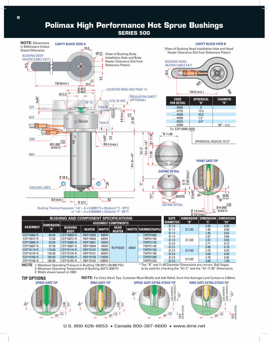
Polimax High Performance Hot Sprue BushingsSerieS 500
BUsHinG and coMPonent sPeciFications
ASSEMBLY DIMENSION “A”
ASSEMBLY COMPONENTSBUSHING
BODY HEATER wATTS HEAD HEATER wATTS THERMOCOUPLE
edP10060-R… 60.00 CeP10060-R… RBP10056 500W
RCP50020 400W
TMP01080edP10072-R… 72.50 CeP10072-R… RBP10069 690W TMP01100edP10085-R… 85.00 CeP10085-R… RBP10081 760W TMP01120edP10097-R… 97.50 CeP10097-R… RBP10094 760W TMP01140edP10110-R… 110.00 CeP10110-R… RBP10107 760W TMP01160edP10135-R… 135.00 CeP10135-R… RBP10131 850W TMP01180edP10160-R… 160.00 CeP10160-R… RBP10158 1100W TMP01200edP10185-R… 185.00 CeP10185-R… RBP10183 1300W TMP01220
GATE DIAMETER
DIMENSION “B”
DIMENSION “C”
DIMENSION “D1”
Ø 1.0Ø 2.00
2.06 0.58Ø 1.2 1.96 0.60Ø 1.4 1.86 0.63Ø 1.6
Ø 3.002.97 0.66
Ø 1.8 2.87 0.69Ø 2.0 2.77 0.73Ø 2.2
Ø 4.003.88 0.78
Ø 2.4 3.78 0.83Ø 2.6 3.68 0.89Ø 2.8 Ø 5.00 4.78 0.96Ø 3.0 4.68 1.05
TIP OPTIONS
note 1: Maximum Operating Pressure in Bushing 138 MPa (20,000 PSi). 2: Maximum Operating Temperature of Bushing 343°C (650°F). 3: Watts shown based on 230V.
* The “B” and 11.00 diameter dimensions are correct. Ball gages to be used for checking the “A1-C” and the “A1-11.50” dimensions.
30°
3.00
“A1”
+0.035+0.020ØT
30°
3.00
“A1”
+0.035+0.020ØT
SPRUE GATE TIP RING GATE TIP SPRUE GATE EXTRA STOCK TIP RING GATE EXTRA STOCK TIP
30°
3.00
(AVE
RAGE
LA
ND
CON
TACT
)
3.00
(AVE
RAGE
LA
ND
CON
TACT
)
EXTR
A ST
OCK
“A1”
18.0
+0.035+0.020ØT
“A1”
+0.035+0.020ØT
EXTR
A ST
OCK
18.0
note: For extra Stock Tips, Customer Must Modify and Add Relief, Such that Average land Contact is 3.00mm.
COOLING LINES
RBP
TMP
CEP
RCP
"R"-"D"
BUSHING BODY HEATER CABLE EXIT
GATING DETAIL
GATING DETAIL
POINT GATE TIP
View B
View A
CAVITY BLOCK VIEW A
LOCATION RING (SEE PAGE 11)
INSULATION SHEET(OPTIONAL)
Bushing Thermal Expansion " A" = A x 0.0000115 x (Setpoint °C - 20°C)or " A" = A x 0.0000064 x (Setpoint °F - 68°F)
R0.4 (max.)
9.5
3.0
9.5
2x45
°
16.5
8.0 (min.)
Ø 34.0
R3
30°
AØ0.02
120.0(min.)
Ø12.0
1x45
°
+0.2+0.3
23.5Ø 49.5Ø 46.0
4.0
Ø51.000+0.000+0.030
R618.0
ØGATE“B”
90°
“A1-
C”
11.5
0
“C”
“D1”
“A1=
A+
Aӯ 11.00
“A1-
11.5
0”
31.5
0+0.0
4+0
.02
5.50
2.50R5.500.5x
45°
R2
Ø14.000Ø 1.0 (min.)Ø 3.0 (max.)
-A- AØ0.02
+0.035+0.020
0.15
0.50
(tan
g.)
Ø 22.5
4.0
(min
.)
“A1=
A+
A”
*
*
5/16-18 UNC CODE FOR DETAIL
SPHERICAL “R”
CHAMFER “D”
…-R000 0…-R155 15.5…-R400 40.0…-R050 1/2”…-R075 3/4”…-d090 90° - incl.
ex: edP10060-R050
SPHeRiCAl RAdiUS: R1/2”
120.0 (min.)
30.0
R40
R30
CAVITY BLOCK VIEW B
BUSHING HEAD HEATER CABLE EXIT
(View of Bushing Body installation Hole and Body Heater Clearance Slot from Stationary Platen)
(View of Bushing Head installation Hole and Head Heater Clearance Slot from Stationary Platen)
note: dimensions in Millimeters Unless Stated Otherwise.

U.S. 800-626-6653 n Canada 800-387-6600 n www.dme.net
9
Polimax Standard Hot Sprue BushingsSerieS 500
30°
RING GATE TIPSPRUE GATE TIP
3.00
30°
“A1”
“A1”
3.00
ØT +0.035+0.020ØT
+0.035+0.020
“A1”
18.0
EXTR
A ST
OCK
18.0
EXTR
A ST
OCK
3.00
(AVE
RAGE
LAN
D CO
NTA
CT)
RING GATE EXTRA STOCK TIP
ØT +0.035+0.020
SPRUE GATE EXTRA STOCK TIP
30°
ØT +0.035+0.020
“A1”
3.00
(AVE
RAGE
LAN
D CO
NTA
CT)
TIP OPTIONS
note 1: Maximum Operating Pressure in Bushing 138 MPa (20,000 PSi) 2: Maximum Operating Temperature of Bushing 288°C (550°F) 3: Watts Shown Based on 230V.
* The “B” and 11.00 diameter dimensions are correct. Ball gages to be used for checking the “A1-C” and “A1-11.50” dimensions.
note: For extra Stock Tips, Customer Must Modify and Add Relief, Such that Average land Contact is 3.00mm.
BUSHING BODYHEATER CABLE EXIT
120.0 (min.)
16.5
12.0
12.0
R6
27.0+0.3+0.2
22.0
CODE FOR DETAIL
DIMENSION “R”
CHAMFER “D”
…-R000 0…-R155 15.5…-R400 40.0…-R050 1/2”…-R075 3/4”…-d090 90° - incl.
ex: BdP10055-R400
SPHeRiCAl RAdiUS 40 mm
BUsHinG and coMPonent sPeciFications
ASSEMBLY DIMENSION “A”
ASSEMBLY COMPONENTSBUSHING
BODY HEATER wATTS THERMOCOUPLE
BdP10055-R… 55.00 CdP10055-R… RBP10056 500W TMP01080BdP10067-R… 67.50 CdP10067-R… RBP10069 690W TMP01100BdP10080-R… 80.00 CdP10080-R… RBP10081 760W TMP01120BdP10092-R… 92.50 CdP10092-R… RBP10094 760W TMP01140BdP10105-R… 105.00 CdP10105-R… RBP10107 760W TMP01160BdP10130-R… 130.00 CdP10130-R… RBP10131 850W TMP01180BdP10155-R… 155.00 CdP10155-R… RBP10158 1100W TMP01200BdP10180-R… 180.00 CdP10180-R… RBP10183 1300W TMP01220
GATE DIAMETER
DIMENSION “B”
DIMENSION “C”
DIMENSION “D1”
Ø 1.0Ø 2.00
2.06 0.58Ø 1.2 1.96 0.60Ø 1.4 1.86 0.63Ø 1.6
Ø 3.002.97 0.66
Ø 1.8 2.87 0.69Ø 2.0 2.77 0.73Ø 2.2
Ø 4.003.88 0.78
Ø 2.4 3.78 0.83Ø 2.6 3.68 0.89Ø 2.8 Ø 5.00 4.78 0.96Ø 3.0 4.68 1.05
View A (View of Bushing Head installation Hole and Head Heater Clearance Slot from Stationary Platen)
90°
“B”
30°
4.01x
45°
Ø 34.0
Ø 60.000
8.0 (min.)Ø22.5
Ø 12.0
Ø 56.0
Ø 70.0
“A1-
11.5
0”
“A1=
A+
A”
R3 “D1”
11.5
0
“C”
“A1-
C”
1x45
°
18.7
0+0.0
2+0
.00
4.0
(min
.)
25.0
0
Ø 3.0 (max.)Ø 1.0 (min.)
R2
0.5x
45°
Ø GATE0.
50 (t
ang.
)0.
15
2.50
5.50
-A-
Ø 14.000AØ0.02
R5.50
+0.035+0.020
R0.4 (máx.)
View A
+0.030–0.000
Ø 11.00
AØ0.02
GATING DETAIL
GATING DETAIL
COOLING LINES
RBP
TMP
CDP
“R”-“D”
POINT GATE TIP
Locating Ring6548Customer to alterlocating ring topress down ontothe bushing head
Bushing Thermal Expansion “ A” = A x 0.0000115 x (Setpoint °C - 20°C)Bushing Thermal Expansion “ A” = A x 0.0000064 x (Setpoint °F - 68°F)
“A1=
A+
A”
*
*
5/16-18 UNC
note: dimensions in Millimeters Unless Stated Otherwise.

U.S. 800-626-6653 n Canada 800-387-6600 n www.dme.net
10
Polimax Standard Hot Sprue BushingsSerieS 500 – nozzle tiPS
PPM
L
+0.008−0.003φ T
φ 0
PPM
+0.008−0.003φ 14
PID
L
C
+0.008−0.003φ T
φ 3.2
10°
tiP diMensions
TIPS DIMENSION “T”
DIMENSION “L”
DIMENSION “C”
Pid10001 14.00 6.00 9.50
Pid10002 18.00 6.00 9.50
Pid10003 14.00 24.00 27.50
Pid10004 18.00 24.00 27.50
Pid10102 25.40 3.00 9.50
Pid10104 25.40 21.00 27.50
SPRUE GATE TIP
tiP diMensions
ASSEMBLYASSEMBLY COMPONENTS
MATERIAL DIMENSION “T”
DIMENSION “O”
DIMENSION “L”NEEDLE RETAINER TIP
PMA10009
PdF10502
PPM10601
WeAR ReSiSTANT
14.00 2.00
6.00PMA10010 PPM10602 14.00 2.50PMA10011 PPM10603 18.00 2.00PMA10012 PPM10604 18.00 2.50PMA10013 PPM10605 14.00 2.00
24.00PMA10014 PPM10606 14.00 2.50PMA10015 PPM10607 18.00 2.00PMA10016 PPM10608 18.00 2.50PMA10109
PdF10802
PPM10601
STANdARd d-M-e
14.00 2.00
6.00PMA10110 PPM10602 14.00 2.50PMA10111 PPM10603 18.00 2.00PMA10112 PPM10604 18.00 2.50PMA10113 PPM10605 14.00 2.00
24.00PMA10114 PPM10606 14.00 2.50PMA10115 PPM10607 18.00 2.00PMA10116 PPM10608 18.00 2.50
RING GATE TIP
ASSEMBLYPoint Gate coMPonents
NEEDLE RETAINER TIP MATERIAL
PVM10002 PdF10502 PPM10609 WeAR ReSiSTANT
PVM10009 PdF10802 PPM10609 STANdARd d-M-e
POINT GATE TIP
U.S. 800-626-6653 n Canada 800-387-6600 n www.dme.net
11
R2
Ø 4.5 (max.)Ø 3.0 (min.)
0.5x
45°
Ø 20.000
R7.50
-A-AØ0.02
+0.034+0.021
4.50 8.50
LOCATING RING–refer to page 14
RBP
RBP
TMP
CEP
CBPView B
View A
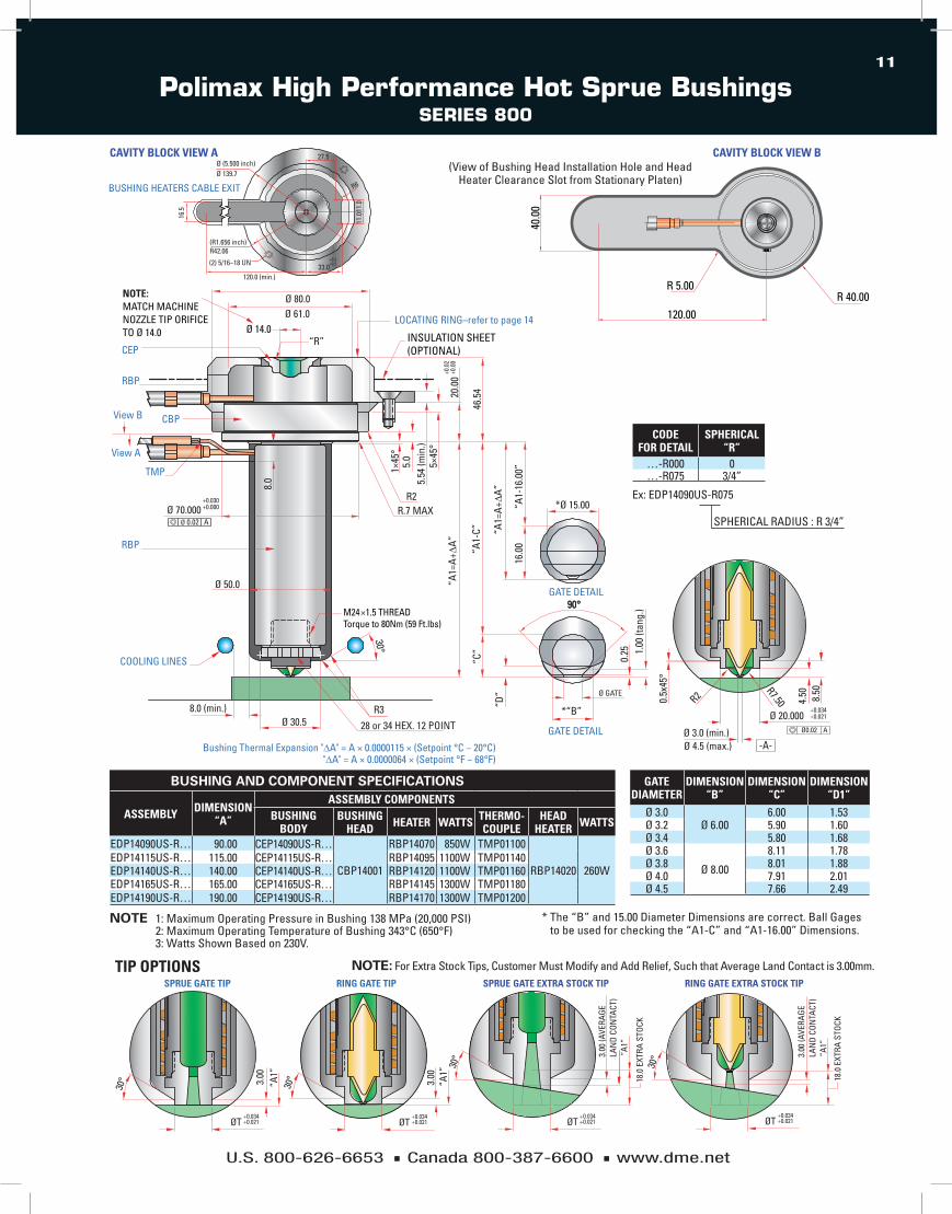
NOTE: MATCH MACHINE NOZZLE TIP ORIFICE TO Ø 14.0
Ø 80.0Ø 61.0
Ø 14.0
Bushing Thermal Expansion "∆A" = A × 0.0000115 × (Setpoint °C − 20°C) "∆A" = A × 0.0000064 × (Setpoint °F − 68°F)
COOLING LINES
R328 or 34 HEX. 12 POINT
R2
“R”
R.7 MAX
30°
Ø 30.58.0 (min.)
Ø 70.000Ø 0.02 A
Ø 50.0 “A1=
A+∆A
”20
.00
1×45
°
5×45
°
5.0
46.5
4
+0.0
2+0
.00
5.54
(min
.)
+0.030+0.000
INSULATION SHEET(OPTIONAL)
90°
GATE DETAIL
*“B”
0.25
Ø GATE
90°
1.00
(tan
g.)
“D”
“C”
M24×1.5 THREADTorque to 80Nm (59 Ft.lbs)
8.0
*Ø 15.00
GATE DETAIL
“A1=
A+∆A
”
“A1-
C”
“A1-
16.0
0”16
.00
TIP OPTIONS
note 1: Maximum Operating Pressure in Bushing 138 MPa (20,000 PSi) 2: Maximum Operating Temperature of Bushing 343°C (650°F) 3: Watts Shown Based on 230V.
SPHeRiCAl RAdiUS : R 3/4”
CODE FOR DETAIL
SPHERICAL “R”
…-R000 0…-R075 3/4”
ex: edP14090US-R075
BUsHinG and coMPonent sPeciFications
ASSEMBLY DIMENSION “A”
ASSEMBLY COMPONENTSBUSHING
BODYBUSHING
HEAD HEATER wATTS THERMO-COUPLE
HEADHEATER wATTS
edP14090US-R… 90.00 CeP14090US-R…
CBP14001
RBP14070 850W TMP01100
RBP14020 260WedP14115US-R… 115.00 CeP14115US-R… RBP14095 1100W TMP01140edP14140US-R… 140.00 CeP14140US-R… RBP14120 1100W TMP01160edP14165US-R… 165.00 CeP14165US-R… RBP14145 1300W TMP01180edP14190US-R… 190.00 CeP14190US-R… RBP14170 1300W TMP01200
GATE DIAMETER
DIMENSION “B”
DIMENSION “C”
DIMENSION “D1”
Ø 3.0Ø 6.00
6.00 1.53Ø 3.2 5.90 1.60Ø 3.4 5.80 1.68Ø 3.6
Ø 8.00
8.11 1.78Ø 3.8 8.01 1.88Ø 4.0 7.91 2.01Ø 4.5 7.66 2.49
note: For extra Stock Tips, Customer Must Modify and Add Relief, Such that Average land Contact is 3.00mm.
16.5
BUSHING HEATERS CABLE EXIT
120.0 (min.)
(2) 5/16–18 UN
Ø (5.500 inch)Ø 139.7
(R1.656 inch)R42.06
R6
33.0+0.3+0.2
27.5
11.0
11.0
CAVITY BLOCK VIEW A
SPRUE GATE TIP
3.00
“A1”
ØT +0.034+0.021
30°
RING GATE TIP
3.00
“A1”
ØT +0.034+0.021
30°
SPRUE GATE EXTRA STOCK TIP
3.00
(AVE
RAGE
LAN
D CO
NTA
CT)
“A1”
18.0
EXT
RA S
TOCK
ØT +0.034+0.021
30°
RING GATE EXTRA STOCK TIP
30° 3.
00 (A
VERA
GELA
ND
CON
TACT
)“A
1”
18.0
EXT
RA S
TOCK
ØT +0.034+0.021
Polimax High Performance Hot Sprue BushingsSerieS 800
* The “B” and 15.00 diameter dimensions are correct. Ball gages to be used for checking the “A1-C” and “A1-16.00” dimensions.
40.0
0
R 5.00R 40.00
120.00
CAVITY BLOCK VIEW B(View of Bushing Head installation Hole and Head
Heater Clearance Slot from Stationary Platen)
U.S. 800-626-6653 n Canada 800-387-6600 n www.dme.net
12
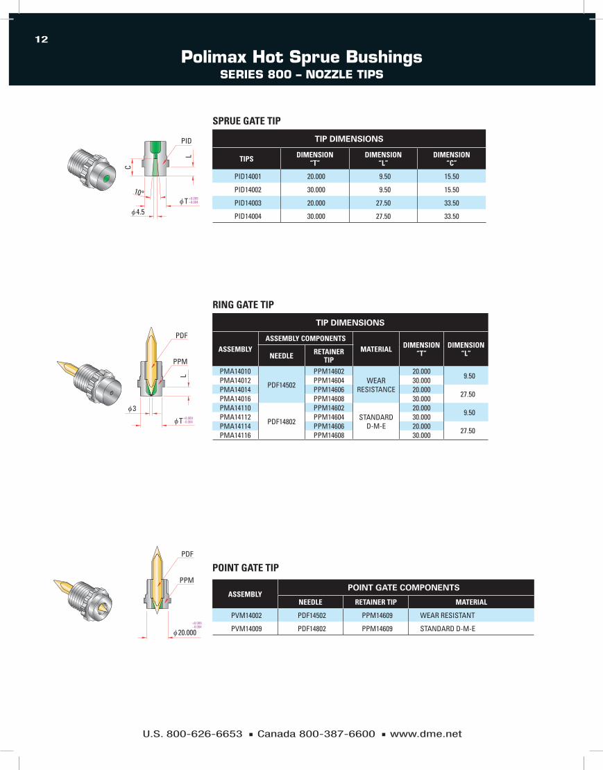
tiP diMensions
TIPS DIMENSION “T”
DIMENSION “L”
DIMENSION “C”
Pid14001 20.000 9.50 15.50
Pid14002 30.000 9.50 15.50
Pid14003 20.000 27.50 33.50
Pid14004 30.000 27.50 33.50
SPRUE GATE TIP
tiP diMensions
ASSEMBLYASSEMBLY COMPONENTS
MATERIAL DIMENSION “T”
DIMENSION “L”NEEDLE RETAINER
TIPPMA14010
PdF14502
PPM14602WeAR
ReSiSTANCe
20.0009.50PMA14012 PPM14604 30.000
PMA14014 PPM14606 20.00027.50PMA14016 PPM14608 30.000
PMA14110
PdF14802
PPM14602STANdARd
d-M-e
20.0009.50PMA14112 PPM14604 30.000
PMA14114 PPM14606 20.000 27.50PMA14116 PPM14608 30.000
RING GATE TIP
ASSEMBLYPoint Gate coMPonents
NEEDLE RETAINER TIP MATERIAL
PVM14002 PdF14502 PPM14609 WeAR ReSiSTANT
PVM14009 PdF14802 PPM14609 STANdARd d-M-e
POINT GATE TIP PDF
PPM
+0.009−0.004
φ 20.000
PPM
L
+0.009−0.004φ T
φ 3
PID
L
C
+0.009−0.004φ T
φ 4.5
10°
Polimax Hot Sprue BushingsSerieS 800 – nozzle tiPS

U.S. 800-626-6653 n Canada 800-387-6600 n www.dme.net
13
200 & 500 SERIES HIGH PERFORMANCE LOCATING RINGS
HOT SPRUE BUSHING ITEM NUMBER Ø d T
200 Series PMl0251 34.0 (1.34”) 18.00 (0.709”)*
200 Series PMl0253 34.0 (1.34”) 5.54 (0.218”)*
500 Series PMl0551 46.0 (1.81”) 18.00 (0.709”)
500 Series PMl0553 46.0 (1.81”) 5.54 (0.218”)
*Alter flange height to suit application and/or alter counterbore depth for locating ring flange in the top clamp plateNOTE: dimensions shown in Millimeters, inches in parenthesis
[2.312]R58.72
DRILLED AND C’SUNK FOR 5/16 DIA. FLAT HEAD SCREW (2)
5/16-18TAPPED THRU (2)
Ø 139.45
Ø 101.35
[5.490]
Ø d
[3.990]
11.0
T15
.00
[2.312]R58.72
DRILLED AND C’SUNK FOR 5/16 DIA. FLAT HEAD SCREW (2)
5/16-18TAPPED THRU (2)
Ø 139.45
Ø 101.35
[5.490]
Ø d
[3.990]
11.0
T15
.00
Polimax® Hot Sprue BushingslocatinG rinGS

U.S. 800-626-6653 n Canada 800-387-6600 n www.dme.net
14
POLIMAx 800 LOCATING RING NA STANDARD CATALOG #PML0853
Polimax® Hot Sprue BushingslocatinG rinGS
45°
45°
5/16 -18UNC Class 2BThru, 2 plc's
A
A
45°
45°
5/16 -18UNC Class 2BThru, 2 plc's
A
A
[2.312]
R58.72[2.312]
R58.72
[3.990]101.35
[1.181]30.00
[2.400]61.0
[5.490]139.45
[0.2
18]
5.54
[0.2
54]
6.46
[1.2
99]
33.0
0
[3.543]90.0
[1.181]30.00
[3.990]101.35
[2.400]61.0
[5.490]139.45
[1.0
45]
26.5
4
[0.7
09]
18.0
0
POLIMAx 800 LOCATING RING NA ExTENDED CATALOG #PML0851
note: Counterbore depth in Top Clamp Plate and/or Top of Flange in locating Ring (can be Altered to Suit Application)
note 1: locating Rings Supplied with (2) 5/16–18 x 1–1/4lg F.H.C.S 2: dimensions in Millimeters Unless Otherwise Stated.

world HeadquartersD-M-E Company 29111 Stephenson HighwayMadison Heights, MI 48071800-626-6653 toll-free tel248-398-6000 tel888-808-4363 toll-free faxwww.dme.net [email protected] e-mail
D-M-E of Canada, Ltd.6210 Northwest DriveMississauga, Ontario Canada L4V 1J6800-387-6600 toll-free tel 905-677-6370 tel800-461-9965 toll-free [email protected] e-mail
D-M-E Europe C.V.B.A.Industriepark NoordB-2800 Mechelen Belgium32-15-215011 tel 32-15-218235 [email protected] e-mail
PM 07/09
D-M-E, an essential resource to the customers it serves worldwide, offers the industry’s broadest range of market-leading products, unsurpassed knowledge and expertise, a global logistics infrastructure that ensures speed and accuracy, and a support organization unrivaled for its ability to assist customers when and where they need it. A complete line of hot runner systems, control systems, mold bases, MUD quick-change mold systems, mold components, moldmaking and molding equipment supplies, and technical services helps customers compete every step of the way.
© Copyright 2008 d-M-e Company All rights reserved. Printed in U.S.A.