poli di mi tecnicolano navigation and control of autonomous vehicles with integrated flight envelope...
TRANSCRIPT

PO
LIPO
LI
di
di M
IM
Itecn
ico
tecn
ico
lano
lano
NAVIGATION AND CONTROL OF AUTONOMOUS VEHICLES WITH INTEGRATED FLIGHT ENVELOPE PROTECTION
C.L. BottassoPolitecnico di Milano
Workshop CRUI-ACARE Napoli, July 14, 2006
NAVIGATION AND CONTROL OF AUTONOMOUS VEHICLES WITH INTEGRATED FLIGHT ENVELOPE PROTECTION
C.L. BottassoPolitecnico di Milano
Workshop CRUI-ACARE Napoli, July 14, 2006
Flig
ht
En
velo
pe P
rote
ctio
n f
or
UA
Vs
Flig
ht
En
velo
pe P
rote
ctio
n f
or
UA
Vs
Flig
ht
En
velo
pe P
rote
ctio
n f
or
UA
Vs
Flig
ht
En
velo
pe P
rote
ctio
n f
or
UA
Vs
POLITECNICO di MILANO
OutlineOutline
• Background on flight envelope protection;
• Proposed research: model-based optimal control with integrated flight envelope protection;
- Envelope-aware path planning (tactical control layer);
- Envelope-aware path tracking (reflexive control layer);
- Adaptive reduced vehicle model;
• Preliminary results;
• Conclusions and outlook.
Flig
ht
En
velo
pe P
rote
ctio
n f
or
UA
Vs
Flig
ht
En
velo
pe P
rote
ctio
n f
or
UA
Vs
Flig
ht
En
velo
pe P
rote
ctio
n f
or
UA
Vs
Flig
ht
En
velo
pe P
rote
ctio
n f
or
UA
Vs
POLITECNICO di MILANO
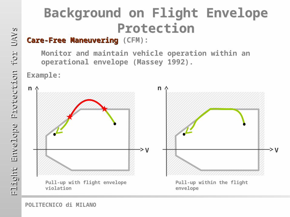
Care-Free ManeuveringCare-Free Maneuvering (CFM):
Monitor and maintain vehicle operation within an operational envelope (Massey 1992).
Example:
Background on Flight Envelope Protection
Background on Flight Envelope Protection
Pull-up with flight envelope violation
V
n
V
n
Pull-up within the flight envelope

Flig
ht
En
velo
pe P
rote
ctio
n f
or
UA
Vs
Flig
ht
En
velo
pe P
rote
ctio
n f
or
UA
Vs
Flig
ht
En
velo
pe P
rote
ctio
n f
or
UA
Vs
Flig
ht
En
velo
pe P
rote
ctio
n f
or
UA
Vs
POLITECNICO di MILANO
Background on Flight Envelope Protection
Background on Flight Envelope Protection
CFM CFM working principle:
Piloted flightPiloted flight:
• CFM cues pilot (often tactile cues through force-feel feedback on active control stick, which can be overridden by the pilot), and/or
• CFM interacts with Flight Control System (FCS), which in turn corrects the command inputs.
Autonomous flightAutonomous flight:
• CFM interacts with trajectory planner (tactical controller) so as to generate a safe-to-be-tracked response profile, and/or
• Interacts with trajectory tracker (reflexive controller), by correcting the command inputs.
V
n 1) Predict limit onset
2) Cue pilot and/or modify control actions so as to avoid boundary violation
Flig
ht
En
velo
pe P
rote
ctio
n f
or
UA
Vs
Flig
ht
En
velo
pe P
rote
ctio
n f
or
UA
Vs
Flig
ht
En
velo
pe P
rote
ctio
n f
or
UA
Vs
Flig
ht
En
velo
pe P
rote
ctio
n f
or
UA
Vs
POLITECNICO di MILANO
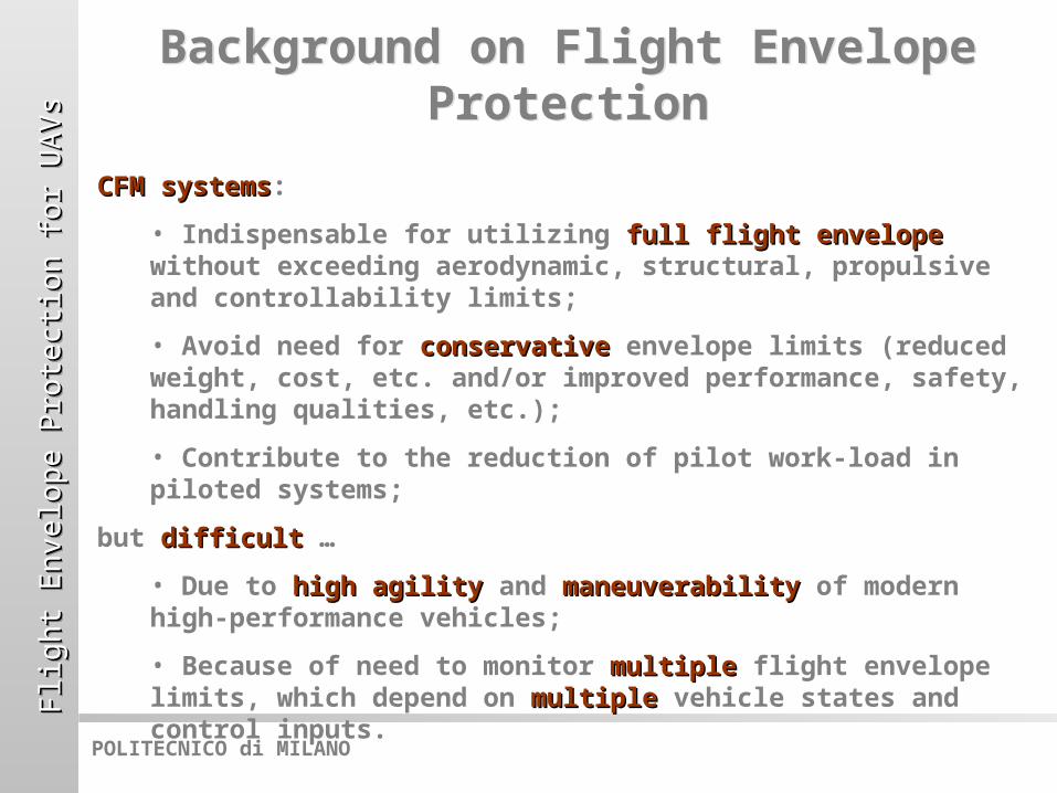
CFM systemsCFM systems:
• Indispensable for utilizing full flight envelopefull flight envelope without exceeding aerodynamic, structural, propulsive and controllability limits;
• Avoid need for conservativeconservative envelope limits (reduced weight, cost, etc. and/or improved performance, safety, handling qualities, etc.);
• Contribute to the reduction of pilot work-load in piloted systems;
but difficultdifficult …
• Due to high agilityhigh agility and maneuverabilitymaneuverability of modern high-performance vehicles;
• Because of need to monitor multiplemultiple flight envelope limits, which depend on multiplemultiple vehicle states and control inputs.
Background on Flight Envelope Protection
Background on Flight Envelope Protection
Flig
ht
En
velo
pe P
rote
ctio
n f
or
UA
Vs
Flig
ht
En
velo
pe P
rote
ctio
n f
or
UA
Vs
Flig
ht
En
velo
pe P
rote
ctio
n f
or
UA
Vs
Flig
ht
En
velo
pe P
rote
ctio
n f
or
UA
Vs
POLITECNICO di MILANO
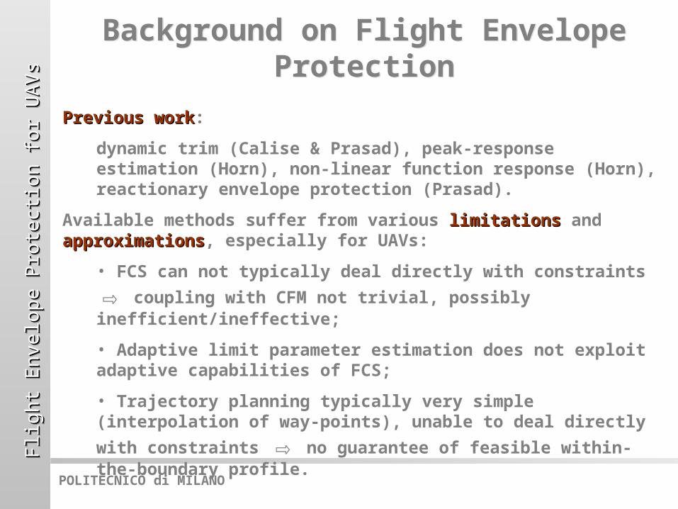
Previous workPrevious work:
dynamic trim (Calise & Prasad), peak-response estimation (Horn), non-linear function response (Horn), reactionary envelope protection (Prasad).
Available methods suffer from various limitationslimitations and approximationsapproximations, especially for UAVs:
• FCS can not typically deal directly with constraints ⇨ coupling with CFM not trivial, possibly inefficient/ineffective;
• Adaptive limit parameter estimation does not exploit adaptive capabilities of FCS;
• Trajectory planning typically very simple (interpolation
of way-points), unable to deal directly with constraints ⇨ no guarantee of feasible within-the-boundary profile.
Background on Flight Envelope Protection
Background on Flight Envelope Protection

Flig
ht
En
velo
pe P
rote
ctio
n f
or
UA
Vs
Flig
ht
En
velo
pe P
rote
ctio
n f
or
UA
Vs
Flig
ht
En
velo
pe P
rote
ctio
n f
or
UA
Vs
Flig
ht
En
velo
pe P
rote
ctio
n f
or
UA
Vs
POLITECNICO di MILANO
Optimal Control CFMOptimal Control CFM
Proposed workProposed work:
Optimal-control model-based tactical and reflexive control architecture with integrated flight envelope protection.
HighlightsHighlights:
• Optimal control can rigorously deal with constraints;
• Optimal-control planning of trajectories (tactical layer)
⇨ guaranteed feasibility;
• Optimal-control tracking (reflexive layer) ⇨ constraints accounted for also at the level of the FCS;
• Adaptive reduced model ⇨ improves both FCS and CFM performance.
Flig
ht
En
velo
pe P
rote
ctio
n f
or
UA
Vs
Flig
ht
En
velo
pe P
rote
ctio
n f
or
UA
Vs
Flig
ht
En
velo
pe P
rote
ctio
n f
or
UA
Vs
Flig
ht
En
velo
pe P
rote
ctio
n f
or
UA
Vs
POLITECNICO di MILANO
UAV Control ArchitectureUAV Control Architecture
Target
Obstacles
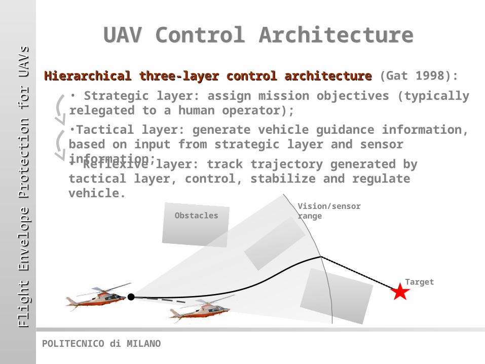
Hierarchical three-layer control architectureHierarchical three-layer control architecture (Gat 1998):
Vision/sensor range
• Strategic layer: assign mission objectives (typically relegated to a human operator);
•Tactical layer: generate vehicle guidance information, based on input from strategic layer and sensor information;• Reflexive layer: track trajectory generated by tactical layer, control, stabilize and regulate vehicle.
Flig
ht
En
velo
pe P
rote
ctio
n f
or
UA
Vs
Flig
ht
En
velo
pe P
rote
ctio
n f
or
UA
Vs
Flig
ht
En
velo
pe P
rote
ctio
n f
or
UA
Vs
Flig
ht
En
velo
pe P
rote
ctio
n f
or
UA
Vs
POLITECNICO di MILANO
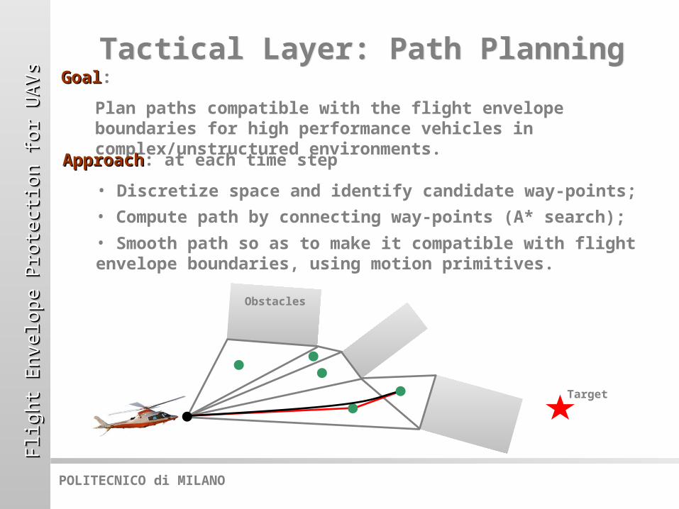
GoalGoal:
Plan paths compatible with the flight envelope boundaries for high performance vehicles in complex/unstructured environments.
Tactical Layer: Path PlanningTactical Layer: Path Planning
Target
ApproachApproach: at each time step
• Discretize space and identify candidate way-points;
• Compute path by connecting way-points (A* search);
• Smooth path so as to make it compatible with flight envelope boundaries, using motion primitives.
Obstacles
Flig
ht
En
velo
pe P
rote
ctio
n f
or
UA
Vs
Flig
ht
En
velo
pe P
rote
ctio
n f
or
UA
Vs
Flig
ht
En
velo
pe P
rote
ctio
n f
or
UA
Vs
Flig
ht
En
velo
pe P
rote
ctio
n f
or
UA
Vs
POLITECNICO di MILANO
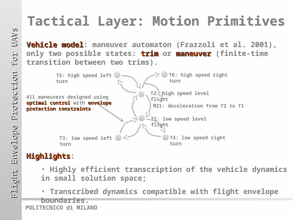
Vehicle modelVehicle model: maneuver automaton (Frazzoli et al. 2001), only two possible states: trimtrim or maneuvermaneuver (finite-time transition between two trims).
HighlightsHighlights:
• Highly efficient transcription of the vehicle dynamics in small solution space;
• Transcribed dynamics compatible with flight envelope boundaries.
Tactical Layer: Motion PrimitivesTactical Layer: Motion Primitives
T1: low speed level flight
T2: high speed level flight
T4: low speed right turn
T3: low speed left turn
T6: high speed right turn
T5: high speed left turn
M21: deceleration from T2 to T1
All maneuvers designed using optimal controloptimal control with envelope envelope protection constraintsprotection constraints

Flig
ht
En
velo
pe P
rote
ctio
n f
or
UA
Vs
Flig
ht
En
velo
pe P
rote
ctio
n f
or
UA
Vs
Flig
ht
En
velo
pe P
rote
ctio
n f
or
UA
Vs
Flig
ht
En
velo
pe P
rote
ctio
n f
or
UA
Vs
POLITECNICO di MILANO
GoalGoal: plan a maneuver which is compatible with the flight envelope boundaries.
Optimal control: min
Subjected to:
• Reduced model equations:
• Boundary conditions: (initial)
(final)
• ConstraintsConstraints:
Tactical Layer: Maneuver Planning Tactical Layer: Maneuver Planning
Ã(y(T0)) 2 [Ã0min;Ã0max
];Ã(y(T)) 2 [ÃTmin
;ÃTmax];
J plan = Á(y;u)¯¯T
+Z T
T0
L(y;u) dt;
f ( _y;y;u;p¤) = 0;
gplan(y;u;T) 2 [gplanmin ;gplan
max ]:
Trajectory to be tracked by reflexive controller
y¤

Flig
ht
En
velo
pe P
rote
ctio
n f
or
UA
Vs
Flig
ht
En
velo
pe P
rote
ctio
n f
or
UA
Vs
Flig
ht
En
velo
pe P
rote
ctio
n f
or
UA
Vs
Flig
ht
En
velo
pe P
rote
ctio
n f
or
UA
Vs
POLITECNICO di MILANO
Reflexive Layer: Trajectory Tracking
Reflexive Layer: Trajectory Tracking
1. Tracking
Plant responsePredictive solutions (reduced model)
2. Steering
Prediction window
Steering window
Tracking cost
Prediction window
Tracking cost
Steering window
Tracking costPrediction window
Steering window
Reference trajectory
Optimal Control: min
Subjected to:
• Reduced model equations:
• Initial conditions:
• ConstraintsConstraints:
f ( _y;y;u;p¤) = 0;
y(T track0 ) = ey0;
gtrack(y;u;T) 2 [gtrackmin ;gtrack
max ]:
GoalGoal: track trajectory while satisfying flight envelope constraints.
J track =
Z T t rack
T t rack0
(jjy ¡ y¤jjS t racky
+jj _ujjS t rack_u
) dt;
Flig
ht
En
velo
pe P
rote
ctio
n f
or
UA
Vs
Flig
ht
En
velo
pe P
rote
ctio
n f
or
UA
Vs
Flig
ht
En
velo
pe P
rote
ctio
n f
or
UA
Vs
Flig
ht
En
velo
pe P
rote
ctio
n f
or
UA
Vs
POLITECNICO di MILANO
Reduced Model AdaptionReduced Model Adaption
1. Tracking
Plant response
3. Reduced model update
Predictive solutions
2. Steering
Prediction window
Steering window
Tracking cost
Prediction error
Prediction window
Tracking cost
Steering window
Prediction error
Tracking costPrediction window
Steering window
Prediction error
Reference trajectory
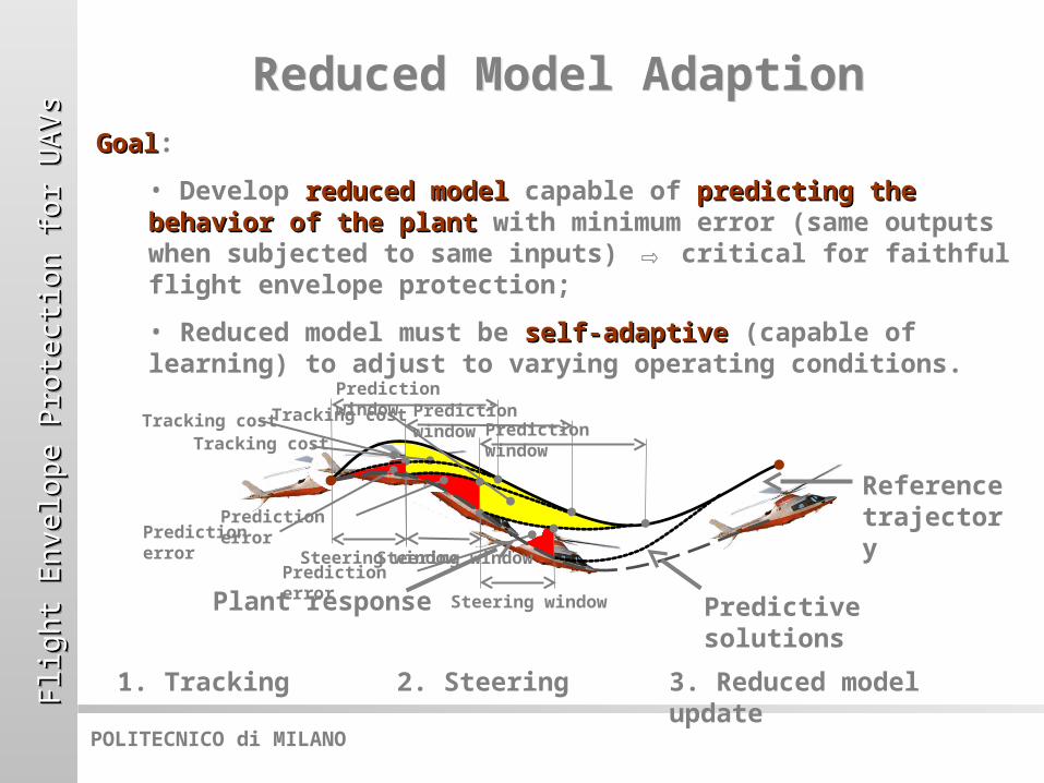
GoalGoal:
• Develop reduced modelreduced model capable of predicting the predicting the behavior of the plantbehavior of the plant with minimum error (same outputs when subjected to same inputs) ⇨ critical for faithful flight envelope protection;
• Reduced model must be self-adaptiveself-adaptive (capable of learning) to adjust to varying operating conditions.

Flig
ht
En
velo
pe P
rote
ctio
n f
or
UA
Vs
Flig
ht
En
velo
pe P
rote
ctio
n f
or
UA
Vs
Flig
ht
En
velo
pe P
rote
ctio
n f
or
UA
Vs
Flig
ht
En
velo
pe P
rote
ctio
n f
or
UA
Vs
POLITECNICO di MILANO
Reduced Model AdaptionReduced Model Adaption
ApproachApproach:
Neural-augmented reference model (Bottasso et al. 2004), using extended Kalman parameter identification.
IdeaIdea:
A non-linear parametric function is identified online to capture the mismatch (defect) between the plant and a non-linear reference vehicle model.
HighlightsHighlights:
• Good predictions even before even before any learningany learning has taken place (otherwise would need extensive pre-training);
• Easier and faster adaption: the defect is typically a small small quantityquantity, if the reference model is well chosen.
Short transient Short transient = =
fast adaptionfast adaption
Reference model
Plant
Augmented reference

Flig
ht
En
velo
pe P
rote
ctio
n f
or
UA
Vs
Flig
ht
En
velo
pe P
rote
ctio
n f
or
UA
Vs
Flig
ht
En
velo
pe P
rote
ctio
n f
or
UA
Vs
Flig
ht
En
velo
pe P
rote
ctio
n f
or
UA
Vs
POLITECNICO di MILANO
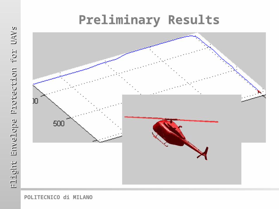
Preliminary ResultsPreliminary Results
Procedures tested in a virtual environmentvirtual environment using a high-fidelity helicopter flight simulator.
Planned path
Acceleration, climb, aggressive turn, descent, deceleration, with prescribed state and control limits:
Rotorcraft trajectory
Rotorcraft trajectory when tracking non-compatible path
Flig
ht
En
velo
pe P
rote
ctio
n f
or
UA
Vs
Flig
ht
En
velo
pe P
rote
ctio
n f
or
UA
Vs
Flig
ht
En
velo
pe P
rote
ctio
n f
or
UA
Vs
Flig
ht
En
velo
pe P
rote
ctio
n f
or
UA
Vs
POLITECNICO di MILANO
Preliminary ResultsPreliminary Results
Flig
ht
En
velo
pe P
rote
ctio
n f
or
UA
Vs
Flig
ht
En
velo
pe P
rote
ctio
n f
or
UA
Vs
Flig
ht
En
velo
pe P
rote
ctio
n f
or
UA
Vs
Flig
ht
En
velo
pe P
rote
ctio
n f
or
UA
Vs
POLITECNICO di MILANO
ConclusionsConclusions
• Proposed a procedure for navigationnavigation and controlcontrol of vehicles which respects the flight enveloperespects the flight envelope;
• Flight envelope constraints are accounted for directlydirectly both at the planningplanning and trackingtracking levels for the first time;
• Applicable to both fixedfixed and rotaryrotary wing vehicles;
• Full system applicable to UAVsUAVs, but components applicable to piloted flightpiloted flight to provide cues to pilots;
• On-line model adaptionmodel adaption improves performance and limit avoidance;
• Basic concept demonstrated in a virtual environment.
Flig
ht
En
velo
pe P
rote
ctio
n f
or
UA
Vs
Flig
ht
En
velo
pe P
rote
ctio
n f
or
UA
Vs
Flig
ht
En
velo
pe P
rote
ctio
n f
or
UA
Vs
Flig
ht
En
velo
pe P
rote
ctio
n f
or
UA
Vs
POLITECNICO di MILANO
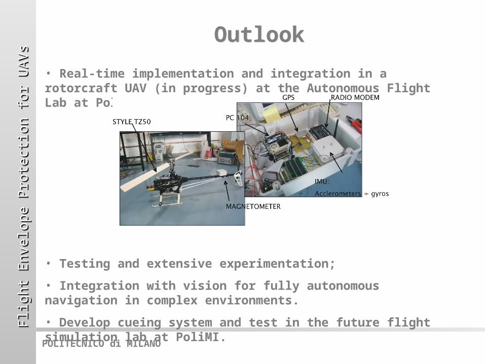
OutlookOutlook
• Real-time implementation and integration in a rotorcraft UAV (in progress) at the Autonomous Flight Lab at PoliMI;
• Testing and extensive experimentation;
• Integration with vision for fully autonomous navigation in complex environments.
• Develop cueing system and test in the future flight simulation lab at PoliMI.

Flig
ht
En
velo
pe P
rote
ctio
n f
or
UA
Vs
Flig
ht
En
velo
pe P
rote
ctio
n f
or
UA
Vs
Flig
ht
En
velo
pe P
rote
ctio
n f
or
UA
Vs
Flig
ht
En
velo
pe P
rote
ctio
n f
or
UA
Vs
POLITECNICO di MILANO
AcknowledgementsAcknowledgements
Work in collaboration with:
A. Croce (Post-Doc), L. Fossati (Graduate student), D. Leonello (Ph.D. candidate), G. Maisano (Ph.D. candidate), R. Nicastro (Graduate student), L. Riviello (Ph.D. candidate), B. Savini (Ph.D. candidate).