polaris dp-20 web guide controller quick start … dp-20 web guide controller quick start setup...
TRANSCRIPT
04/14/2008 © 2008 Fife Corporation. All rights reserved. Figure Sheet 2-248
POLARIS DP-20
WEB GUIDE CONTROLLER QUICK START SETUP MANUAL
1A
AUTOMATIC
× -ãããããÜÜÜÜÜ+
POLARIS DP-20 WEB GUIDE CONTROLLER

04/14/2008 © 2008 Fife Corporation. All rights reserved. Figure Sheet 248
This page is intentionally blank.

POLARIS DP-20 WEB GUIDE CONTROLLER
QUICK START SETUP MANUAL
04/14/2008 Page i of iv Figure Sheet 2-248
COPYRIGHT COPYRIGHT INFORMATION All of the information herein is the exclusive proprietary property of Fife Corporation, and is disclosed with the understanding that it will be retained in confidence and will be used only for the purpose intended. Any reproduction of this Instruction Manual, in any form, in whole or in part, requires the prior written consent of Fife Corporation. The information given in this Instruction Manual is subject to change without notice. Periodically there will be updates to this manual. The latest version is available at www.fife.com or by calling Fife Corporation. This Instruction Manual has been compiled with the greatest possible care and attention; however, the possibility of error cannot be completely excluded. Fife Corporation accepts no legal liability for incorrect information given and the consequences arising there from. Copyright ©2008 Fife Corporation. All rights reserved. This Instruction Manual is intended to be used in addition to the Polaris DP-20 Web Guide Controller User Manual, Figure Sheet 1-862.

04/14/2008 Page ii of iv Figure Sheet 2-248
This page is intentionally blank.
POLARIS DP-20 WEB GUIDE CONTROLLER
QUICK START SETUP MANUAL
04/14/2008 Page iii of iv Figure Sheet 2-248
TABLE OF CONTENTS
COPYRIGHT.................................................................................................................................................. i
COPYRIGHT INFORMATION............................................................................................ i TABLE OF CONTENTS .............................................................................................................................. iii FEATURES................................................................................................................................................... 1
POLARIS DP-20 GENERAL INFORMATION ................................................................... 1 DISPLAY DEFINITIONS ................................................................................................... 1 KEYPAD FUNCTIONS AND DEFINITIONS ..................................................................... 2
OPERATION................................................................................................................................................. 3 SYSTEM SETUP .............................................................................................................. 3 BASIC SYSTEMS AND CABLE CONNECTION DIAGRAMS........................................... 5

04/14/2008 Page iv of iv Figure Sheet 2-248
This page is intentionally blank.
POLARIS DP-20 WEB GUIDE CONTROLLER
QUICK START SETUP MANUAL
04/14/2008 Page 1 of 6 Figure Sheet 2-248
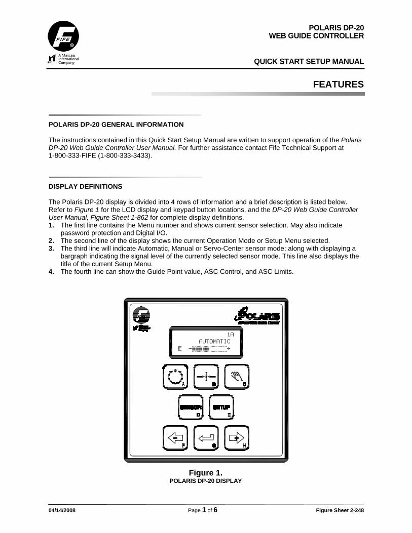
FEATURES POLARIS DP-20 GENERAL INFORMATION The instructions contained in this Quick Start Setup Manual are written to support operation of the Polaris DP-20 Web Guide Controller User Manual. For further assistance contact Fife Technical Support at 1-800-333-FIFE (1-800-333-3433). DISPLAY DEFINITIONS The Polaris DP-20 display is divided into 4 rows of information and a brief description is listed below. Refer to Figure 1 for the LCD display and keypad button locations, and the DP-20 Web Guide Controller User Manual, Figure Sheet 1-862 for complete display definitions. 1. The first line contains the Menu number and shows current sensor selection. May also indicate
password protection and Digital I/O. 2. The second line of the display shows the current Operation Mode or Setup Menu selected. 3. The third line will indicate Automatic, Manual or Servo-Center sensor mode; along with displaying a
bargraph indicating the signal level of the currently selected sensor mode. This line also displays the title of the current Setup Menu.
4. The fourth line can show the Guide Point value, ASC Control, and ASC Limits.
Figure 1.
POLARIS DP-20 DISPLAY
1A
AUTOMATIC
× -ãããããÜÜÜÜÜ+
POLARIS DP-20 WEB GUIDE CONTROLLER
QUICK START SETUP MANUAL
04/14/2008 Page 2 of 6 Figure Sheet 2-248
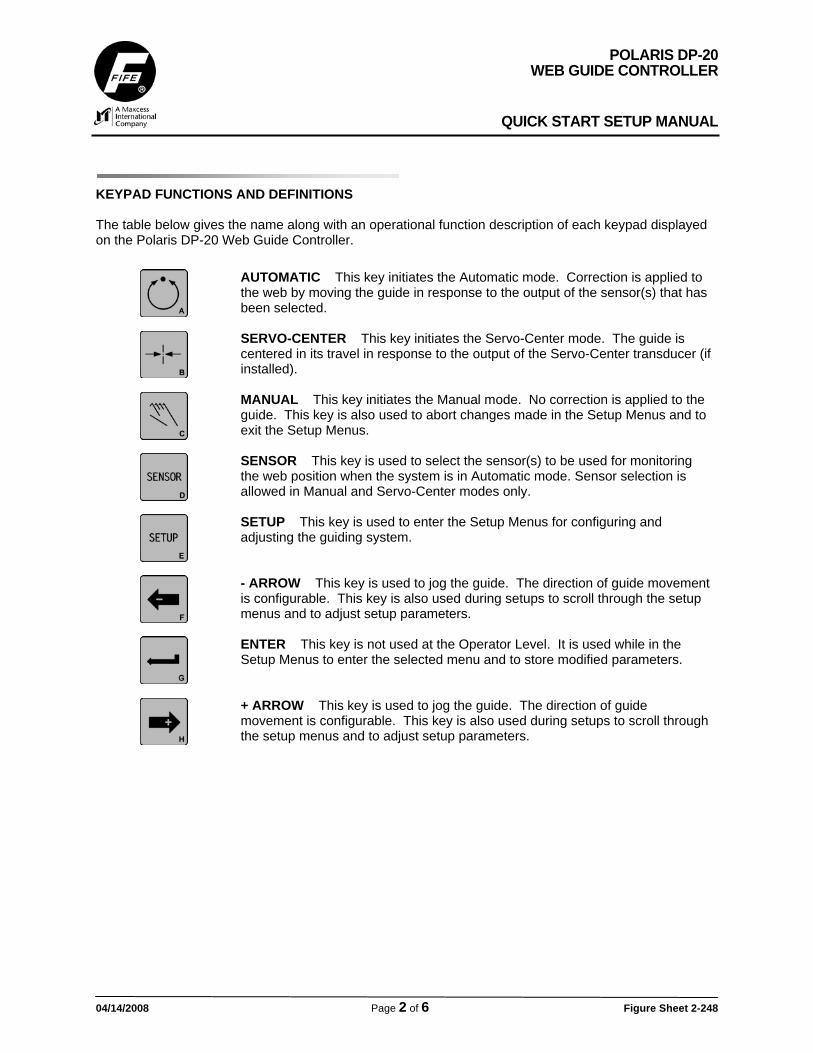
KEYPAD FUNCTIONS AND DEFINITIONS The table below gives the name along with an operational function description of each keypad displayed on the Polaris DP-20 Web Guide Controller.
AUTOMATIC This key initiates the Automatic mode. Correction is applied to the web by moving the guide in response to the output of the sensor(s) that has been selected.
SERVO-CENTER This key initiates the Servo-Center mode. The guide is centered in its travel in response to the output of the Servo-Center transducer (if installed).
MANUAL This key initiates the Manual mode. No correction is applied to the guide. This key is also used to abort changes made in the Setup Menus and to exit the Setup Menus.
SENSOR This key is used to select the sensor(s) to be used for monitoring the web position when the system is in Automatic mode. Sensor selection is allowed in Manual and Servo-Center modes only.
SETUP This key is used to enter the Setup Menus for configuring and adjusting the guiding system.
- ARROW This key is used to jog the guide. The direction of guide movement is configurable. This key is also used during setups to scroll through the setup menus and to adjust setup parameters.
ENTER This key is not used at the Operator Level. It is used while in the Setup Menus to enter the selected menu and to store modified parameters.
+ ARROW This key is used to jog the guide. The direction of guide movement is configurable. This key is also used during setups to scroll through the setup menus and to adjust setup parameters.
POLARIS DP-20 WEB GUIDE CONTROLLER
QUICK START SETUP MANUAL
04/14/2008 Page 3 of 6 Figure Sheet 2-248
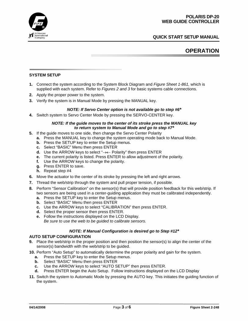
OPERATION SYSTEM SETUP 1. Connect the system according to the System Block Diagram and Figure Sheet 1-861, which is
supplied with each system. Refer to Figures 2 and 3 for basic systems cable connections. 2. Apply the proper power to the system. 3. Verify the system is in Manual Mode by pressing the MANUAL key.
NOTE: If Servo Center option is not available go to step #6* 4. Switch system to Servo Center Mode by pressing the SERVO-CENTER key.
NOTE: If the guide moves to the center of its stroke press the MANUAL key to return system to Manual Mode and go to step #7*
5. If the guide moves to one side, then change the Servo Center Polarity a. Press the MANUAL key to change the system operating mode back to Manual Mode. b. Press the SETUP key to enter the Setup menus. c. Select “BASIC” Menu then press ENTER d. Use the ARROW keys to select “→← Polarity” then press ENTER e. The current polarity is listed. Press ENTER to allow adjustment of the polarity. f. Use the ARROW keys to change the polarity. g. Press ENTER to save. h. Repeat step #4
6. Move the actuator to the center of its stroke by pressing the left and right arrows. 7. Thread the web/strip through the system and pull proper tension, if possible. 8. Perform “Sensor Calibration” on the sensor(s) that will provide position feedback for this web/strip. If
two sensors are being used in a center-guiding application they must be calibrated independently. a. Press the SETUP key to enter the Setup menus. b. Select “BASIC” Menu then press ENTER c. Use the ARROW keys to select “CALIBRATION” then press ENTER. d. Select the proper sensor then press ENTER. e. Follow the instructions displayed on the LCD Display.
Be sure to use the web to be guided to calibrate sensors.
NOTE: If Manual Configuration is desired go to Step #12* AUTO SETUP CONFIGURATION 9. Place the web/strip in the proper position and then position the sensor(s) to align the center of the
sensor(s) bandwidth with the web/strip to be guided. 10. Perform “Auto Setup” to automatically determine the proper polarity and gain for the system.
a. Press the SETUP key to enter the Setup menus. b. Select “BASIC” Menu then press ENTER c. Use the ARROW keys to select “AUTO SETUP” then press ENTER. d. Press ENTER begin the Auto Setup. Follow instructions displayed on the LCD Display
11. Switch the system to Automatic Mode by pressing the AUTO key. This initiates the guiding function of the system.

POLARIS DP-20 WEB GUIDE CONTROLLER
QUICK START SETUP MANUAL
04/14/2008 Page 4 of 6 Figure Sheet 2-248
OPTIONAL MANUAL CONFIGURATION 12. *To manually change the Polarity.
a. Press the SETUP key to enter the Setup menus. b. Select “BASIC” Menu then press ENTER c. Use the ARROW keys to select “GUIDE POLARITY” then press ENTER. d. The current polarity is listed. Press ENTER to allow adjustment of the polarity. e. Use the ARROW keys to change the polarity. f. Press ENTER to save.
13. To manually change the System Gain. a. Press the SETUP key to enter the Setup menus. b. Select “BASIC” Menu then press ENTER c. Use the ARROW keys to select “GAIN” then press ENTER. d. Press ENTER to allow adjustment of the Gain. e. The current gain is listed. Use the ARROW keys to change the Gain. f. Press ENTER to save.
14. To manually change the Guidepoint. a. Press the SETUP key to enter the Setup menus. b. Select “BASIC” Menu then press ENTER c. Use the ARROW keys to select “GUIDEPOINT” then press ENTER. d. Press ENTER to allow adjustment of the Guidepoint. e. The current gain is listed. Use the ARROW keys to change the Gain. f. Press ENTER to save.
POLARIS DP-20 WEB GUIDE CONTROLLER
QUICK START SETUP MANUAL
04/14/2008 Page 5 of 6 Figure Sheet 2-248
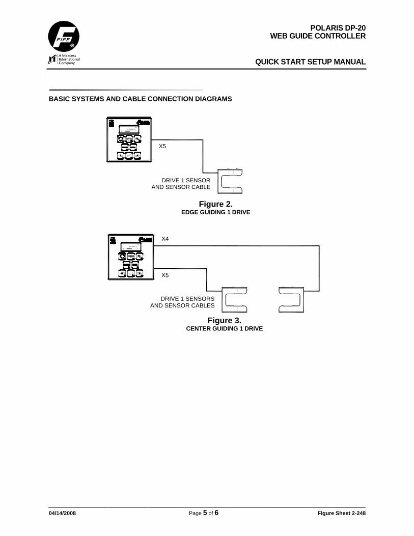
BASIC SYSTEMS AND CABLE CONNECTION DIAGRAMS
X5
DRIVE 1 SENSORAND SENSOR CABLE
1A
AUTOMATIC
× -ãããããÜÜÜÜÜ+
X5
X4
DRIVE 1 SENSORSAND SENSOR CABLES
1A
AUTOMATIC
× -ãããããÜÜÜÜÜ+
Figure 2. EDGE GUIDING 1 DRIVE
Figure 3. CENTER GUIDING 1 DRIVE

04/14/2008 Page 6 of 6 Figure Sheet 2-248
FIFE CORPORATION222 W. Memorial Road, Oklahoma City, OK 73114-2317, USA / Post Office Box 26508, Oklahoma City, OK 73126-0508, USA
Phone: 405.755.1600 / 800.639.3433 / Fax: 405.755.8425 / E-mail: [email protected] / Web: www.fife.com