pnozmulti presses gb
DESCRIPTION
PNOZmulti Presses GBTRANSCRIPT
Supplement to Technical Catalogue - March 2005 edition
Configuration guide
PNOZmulti Modular Safety SystemSafety Solutions For Presses
Contents
1Pilz GmbH & Co. KG, Sichere Automation, Felix-Wankel-Straße 2, 73760 Ostfildern, Germany, Telephone: +49 711 3409-0, Telefax: +49 711 3409-133, E-Mail: [email protected] Status: 03/05
Contents Page
Safety solutions for pressesIntroduction 1-1
Definition of symbols 1-1Safety 2-1
Intended use 2-1Press applications 2-1
Press elements 3-1Overview 3-1
Press elements 3-1Input and output parameters of the elements 3-2
Pulse detection 3-3Function 3-3Input parameters 3-3Output parameters 3-3Options 3-3Diagnostic word 3-3Safety guidelines 3-3
Run monitoring/broken shearpin monitoring 3-4Function 3-4Input parameters 3-4Output parameters 3-4Options 3-4Diagnostic word 3-4Safety guidelines 3-4
Rotary cam arrangement monitoring 3-5Function 3-5Input parameters 3-5Output parameters 3-5Options 3-5Diagnostic word 3-5Safety guidelines 3-5Timing diagram 3-6
Contents
2Pilz GmbH & Co. KG, Sichere Automation, Felix-Wankel-Straße 2, 73760 Ostfildern, Germany, Telephone: +49 711 3409-0, Telefax: +49 711 3409-133, E-Mail: [email protected] Status: 03/05
Contents Page
Safety solutions for pressesLight curtain 3-7
Function 3-7Input parameters 3-7Output parameters 3-7Options 3-7Diagnostic word 3-7Safety guidelines 3-7
Set-up operating mode 3-8Function 3-8Input parameters 3-9Output parameters 3-9Options 3-9Diagnostic word 3-9Safety guidelines 3-9
Single stroke operating mode 3-9Function 3-9Input parameters 3-9Output parameters 3-10Options 3-10Diagnostic word 3-10Safety guidelines 3-10
Automatic operating mode 3-11Function 3-11Input parameters 3-11Output parameters 3-11Options 3-11Diagnostic word 3-11Safety guidelines 3-11
Press safety valves 3-12Function 3-12Input parameters 3-12Output parameters 3-12

Contents
3Pilz GmbH & Co. KG, Sichere Automation, Felix-Wankel-Straße 2, 73760 Ostfildern, Germany, Telephone: +49 711 3409-0, Telefax: +49 711 3409-133, E-Mail: [email protected] Status: 03/05
Contents Page
Safety solutions for pressesOptions 3-12Diagnostic word 3-12
Example 4-1Introduction 4-1Rotary cam arrangement monitoring and run monitoring 4-2Static conditions (e.g. E-STOP, safety gate) 4-3Control devices 4-4Static enable, EN1 4-5Start enable, EN2 and safety enable, EN3 4-6Operating modes 4-7Power supply for light curtain 4-8Light curtain, cycle mode 4-9Set-up operating mode 4-10Single stroke operating mode, start via two-hand buttons at top dead centre 4-11Single stroke operating mode, start via two-hand buttons 4-12Single stroke operating mode, start via foot switch 4-13Single stroke operating mode, light curtain, 1-break 4-14Single stroke operating mode, light curtain, 2-break 4-15Automatic operating mode 4-16Controlling the press safety valve 4-17Displaying the “Waiting for acknowledgement” diagnostic word 4-18Displaying the diagnostic word for light curtains 4-19
4Pilz GmbH & Co. KG, Sichere Automation, Felix-Wankel-Straße 2, 73760 Ostfildern, Germany, Telephone: +49 711 3409-0, Telefax: +49 711 3409-133, E-Mail: [email protected] Status: 03/05
Introduction
Safety solutions for presses
1-1Pilz GmbH & Co. KG, Sichere Automation, Felix-Wankel-Straße 2, 73760 Ostfildern, Germany, Telephone: +49 711 3409-0, Telefax: +49 711 3409-133, E-Mail: [email protected] Status: 03/05
The “Safety solutions for presses” configu-ration guide describes the press elements ofthe PNOZmulti Configurator, includes safetyguidelines and explains the use of thesoftware using a detailed example.
The configuration guide is divided into thefollowing chapters:1 IntroductionThe introduction is designed to familiariseyou with the contents, structure and specificorder of this manual.2 SafetyThis chapter must be read, as it containsimportant information on safety regulationsand standards.3 Press elementsThis chapter explains the press elements indetail and contains important safety infor-mation on using the software.4 ExampleThis chapter contains a detailed example onusing the software.
Definition of symbols
Information in this manual that is of particu-lar importance can be identified as follows:
DANGER!This warning must be heeded! Itwarns of a hazardous situation thatposes an immediate threat ofserious injury and death, andindicates preventive measures thatcan be taken.
WARNING!This warning must be heeded! Itwarns of a hazardous situation thatcould lead to serious injury anddeath and indicates preventivemeasures that can be taken.
CAUTION!This refers to a hazard that can leadto a less serious or minor injury plusmaterial damage, and also providesinformation on preventive measuresthat can be taken.
NOTICEThis describes a situation in whichthe unit(s) could be damaged andalso provides information on preven-tive measures that can be taken.
INFORMATIONThis gives advice on applications andprovides information on specialfeatures, as well as highlighting areaswithin the text that are of particularimportance.

1-2Pilz GmbH & Co. KG, Sichere Automation, Felix-Wankel-Straße 2, 73760 Ostfildern, Germany, Telephone: +49 711 3409-0, Telefax: +49 711 3409-133, E-Mail: [email protected] Status: 03/05

Safety
Safety solutions for presses
2-1Pilz GmbH & Co. KG, Sichere Automation, Felix-Wankel-Straße 2, 73760 Ostfildern, Germany, Telephone: +49 711 3409-0, Telefax: +49 711 3409-133, E-Mail: [email protected] Status: 03/05
Intended use
The PNOZmulti Configurator software isdesigned to configure units from thePNOZmulti modular safety system for useon E-STOP equipment and safety circuits, inaccordance with EN 60204-1 (VDE 0113-1),11/98 and IEC 60204-1, 12/97.
Press applicationsThe press elements in the PNOZmultiConfigurator are designed for the controland monitoring of presses and for pressupgrade.The press elements are only available inconjunction with the PNOZ m2p basemodule.All of the functions required for a press areavailable.This includes:• Operating modes
- Setup- Single stroke- Automatic
• Monitoring a mechanical rotary camarrangement
• Run monitoring• Monitoring electrosensitive protective
equipment (cycle mode)• Control and monitoring of a press safety
valve
Be sure that you observe the warning notesgiven in the other parts of this configurationguide and in the PNOZmulti technicalcatalogue. These are highlighted visuallythrough the use of symbols.
CAUTION!Failure to observe the safetyregulations in this configurationguide and in the PNOZmulti techni-cal catalogue will render thewarranty invalid.
StandardsTo use the press elements correctly, you willneed to have a good knowledge of therelevant standards and directives. Thefollowing statutory instruments give anoverview of the most important standards:• Mechanical presses, EN 692• Hydraulic presses, EN 693• Hydraulic press brakes, EN 12622• Safety of machinery - basic terminology,
EN 292-1 and EN 292-2• Electrical equipment of machines,
EN 60204-1• Electrosensitive protective equipment,
EN 61496-1• Safety of machinery, EN 954-1Please note this is not an exhaustive list ofsafety standards and directives.

2
2-2Pilz GmbH & Co. KG, Sichere Automation, Felix-Wankel-Straße 2, 73760 Ostfildern, Germany, Telephone: +49 711 3409-0, Telefax: +49 711 3409-133, E-Mail: [email protected] Status: 03/05

Press elements
3-1Pilz GmbH & Co. KG, Sichere Automation, Felix-Wankel-Straße 2, 73760 Ostfildern, Germany, Telephone: +49 711 3409-0, Telefax: +49 711 3409-133, E-Mail: [email protected] Status: 03/05
Overview
Press elementsThe safety solutions for presses compriseindividual elements that contain specificfunctions. The individual elements arecompatible with each other.
INFORMATIONThe press elements in the PNOZmultiConfigurator are only available if youhave selected the PNOZ m2p basemodule.
Camshaft
Sequenceoperating modes
Shearpin breakage
E-STOP (category 4)
Two-handorfoot switch
Electrosensitiveprotective equipment
StandstillSpeedPress safety valve (PSV)
PNOZ m2p
PNOZmulti Configurator
Control and monitoring of a press
Operating modesCamshaft
Light curtainSafety valves
Valve control, single valve
Valve control, double valve
Valve control, directional valve
Light curtain (ESPE), cycle mode1 to 5-cycle mode possibleStandard mode or Sweden mode
Pulse detection: Detects and registers pulse edge change at CI input
Run monitoringNumber of strokes and pulses per revolution configurable
Rotary cam arrangement monitoringRun-up cam (HL), overrun cam (NL), dynamic cam (DY)
Setup
Single stroke
Automatic
Overview of the press elements in the PNOZmulti Configurator

Press elements
3-2Pilz GmbH & Co. KG, Sichere Automation, Felix-Wankel-Straße 2, 73760 Ostfildern, Germany, Telephone: +49 711 3409-0, Telefax: +49 711 3409-133, E-Mail: [email protected] Status: 03/05
Input and output parameters of theelementsThe inputs and outputs of the press ele-ments have icons. These icons make it
Icon Short description
MODE
ON
STOP
PULSE
CAM1
CAM2
CAM3
TOP
UP
LC
EN1
EN2
Function
Operating mode, the input activates the element
Start, a start command is issued with the 0/1 pulse edge atON. Start is only executed when all enable conditions havebeen fulfilled.
Stops the automatic mode logic element
Pulses that generate pulse detection and are polled by runmonitoring
Overrun cam, input parameter of rotary cam arrangementmonitoring logic element
Run-up cam, input parameter of rotary cam arrangementmonitoring logic element
Dynamic cam, input parameter of rotary cam arrangementmonitoring logic element
Top dead centre, formed by the rotary cam arrangementmonitoring logic element and polled by the operatingmodes logic element.
Press in run-up or enable, formed by the rotary cam ar-rangement monitoring logic element and polled by theoperating modes logic element.
Light curtain, LC = 1: Protected field clear
Static enable, must be present for the press stroke.If EN1 = 0, the press immediately stops.
Start enable, must be present for the press start-up. During the press stroke, EN2 can change to zero.
Overview
Function
Safety enable, this enable can be overridden (taken over) by UP input parameter.
Press start, start input of valves
Press start, second start input of directional valve
Input of feedback loop for valve 1
Input of feedback loop for valve 2
Short description
EN3
P_ON1
P_ON2
FB1
FB2
Iconeasier to link elements and serve to providemore clarity
Press elements
3-3Pilz GmbH & Co. KG, Sichere Automation, Felix-Wankel-Straße 2, 73760 Ostfildern, Germany, Telephone: +49 711 3409-0, Telefax: +49 711 3409-133, E-Mail: [email protected] Status: 03/05
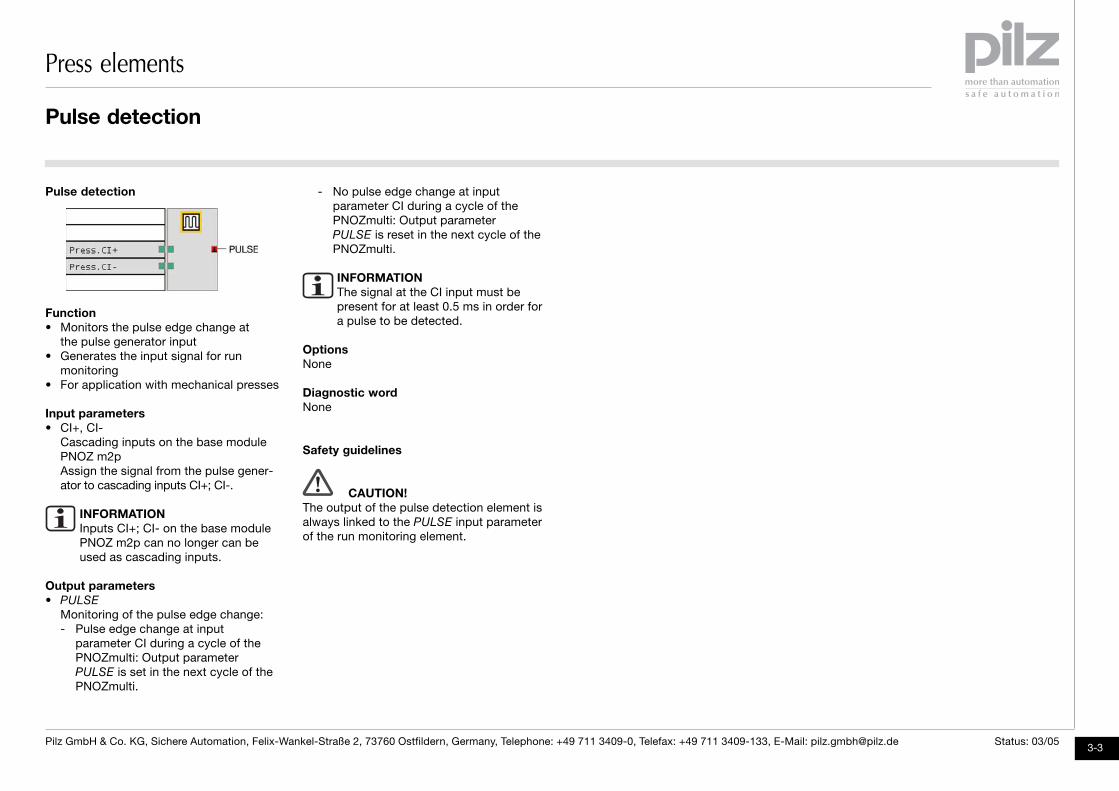
Pulse detection - No pulse edge change at inputparameter CI during a cycle of thePNOZmulti: Output parameterPULSE is reset in the next cycle of thePNOZmulti.
INFORMATIONThe signal at the CI input must be present for at least 0.5 ms in order for a pulse to be detected.
OptionsNone
Diagnostic wordNone
Safety guidelines
CAUTION!The output of the pulse detection element isalways linked to the PULSE input parameterof the run monitoring element.
Function• Monitors the pulse edge change at
the pulse generator input• Generates the input signal for run
monitoring• For application with mechanical presses
Input parameters• CI+, CI-
Cascading inputs on the base modulePNOZ m2pAssign the signal from the pulse gener-ator to cascading inputs CI+; CI-.
INFORMATIONInputs CI+; CI- on the base modulePNOZ m2p can no longer can be used as cascading inputs.
Output parameters• PULSE
Monitoring of the pulse edge change:- Pulse edge change at input
parameter CI during a cycle of thePNOZmulti: Output parameterPULSE is set in the next cycle of thePNOZmulti.
Pulse detection

Press elements
3-4Pilz GmbH & Co. KG, Sichere Automation, Felix-Wankel-Straße 2, 73760 Ostfildern, Germany, Telephone: +49 711 3409-0, Telefax: +49 711 3409-133, E-Mail: [email protected] Status: 03/05
Run monitoring/broken shearpinmonitoring
• Reset
Resets error messages and sets theenable output parameterReset = 1/0 pulse edge: Enable = 1
Output parameters• Enable
EnableEnable = 0: No enable, fault detectedEnable = 1: Enable via Reset = 1/0 pulseedge
Options• Strokes per minute, pulses per rotation
The PNOZmulti Configurator requires twopress characteristics in order to monitorit:- Number of press strokes per minute
Permitted value range: 10 ... 200- Pulses per rotation on the gear on the
rotary cam arrangementPermitted value range: 1 ... 99
The PNOZmulti Configurator calculatesthe monitoring time from the valueswhich have been entered:
t [ms] = (60,000/strokes x pulses) x 1.5The monitoring time starts with the 1/0pulse edge of the PULSE inputparameter. PULSE must return to a 0/1pulse edge within the monitoringtime.
• Start-up timeWaiting time for fault detection during thestart phase of the pressPermitted value range: 50 ... 400 ms
Diagnostic wordMessages can be polled in the PNOZmultiConfigurator in bit mode and additionallylinked in the program.• Bit 2: Waiting for acknowledgement• Bit 8: Start override has elapsed• Bit 9: Monitoring time has elapsed
Safety guidelines
CAUTION!• If the mechanical camshaft is indirectly
powered (e.g. via a chain), run monitoringis required.
• The PULSE input parameter must alwaysbe linked to the PULSE output parameterof the pulse detection logic element.
Function• The element monitors the pulses sup-
plied by the pulse detection element.• Monitoring is activated with the ON input
parameter. If ON=1, pulses must bedetected at the PULSE input parameterwithin the specified times.
• For application with mechanical presses
Input parameters• PULSE
Pulse detection output, shearpinbreakage initiator signalAssign the PULSE input parameter to thePULSE output parameter of the pulsedetection logic element.
• ON
Start of monitoring, press safety valve onON = 0: Monitoring inactiveON = 1: Monitoring activeAssign the ON input parameter to theoutput which drives the press safetyvalve.
Run monitoring

Press elements
3-5Pilz GmbH & Co. KG, Sichere Automation, Felix-Wankel-Straße 2, 73760 Ostfildern, Germany, Telephone: +49 711 3409-0, Telefax: +49 711 3409-133, E-Mail: [email protected] Status: 03/05
Rotary cam arrangement monitoring Overrun monitoring activeIf a dynamic cam is not used, thenCAM1 = 0/1 pulse edge sets theTOP output parameter.
• CAM2
Run-up cam signalThe signal begins at approximatelybottom dead centre (BDC) and maybriefly overlap with the overrun (NL) cam.CAM2 = 1: Enable (UP output parameter)for single stroke operating modeCAM2 signal = 1/0 pulse edge: Safetystop (redundant switch-off at top deadcentre (TDC)
• CAM3
Dynamic cam (optional)CAM3 = 1/0 pulse edge: TOP is setWith the dynamic cam, the overrun camis extended to the front so that the presscomes to a proper stop at top deadcentre (TDC), even at higher stroke rates.The signal begins at approximatelybottom dead centre (BDC) and must endbefore the overrun (NL) cam.If the dynamic cam fails then a safeswitch-off is still provided via the me-chanical run-up (HL) and overrun (NL)cams.The logic element can also be configuredwithout dynamic cams. See Options.
• Reset
Resets error messages and sets the EN
enableReset = 1/0 pulse edge: Enable = 1
Output parameters• Enable
EnableEnable = 0: Enable is blockedEnable = 1: this function is free of faults;is set via Reset = 1/0 pulse edge.The EN enable should be a condition forthe static enable (EN1 input parameter) ofthe operating modes logic element.
• TOP
Press stop, top dead centre (TDC)TOP = 0: TDC region not yet reachedTOP = 0/1 pulse edge: TDC regionreachedThe signal is triggered by a 1/0 pulseedge at the CAM3 input parameter. If noseparate dynamic cam is used, the signalis triggered by the 0/1 pulse edge of theCAM1 signal.TOP = 1: Press is in the TDC regionThe signal is reset by a 1/0 pulse edge atthe CAM1 input parameter.Assign the TOP output parameter to theTOP input parameter of the operatingmodes logic element.
• UP
Enable/run-up activeAutomatic run-up in single strokeUP = 1: From bottom dead centre to thestart of the region of top dead centreCAM2 = 0/1 pulse edge sets UP
CAM1 = 0/1 pulse edge resets UP
If CAM2 = 0, UP always = 0Assign the output parameter UP to theinput parameter UP of the operatingmodes logic element.
Options• Operation with dynamic cam
You can configure the system so that adynamic cam will be used.
Diagnostic word• Bit 2: Waiting for acknowledgement• Bit 8: Overrun monitoring has responded• Bit 9: Feasibility error 1: NL = 1/0 pulse
edge and HL = 1• Bit 10: Feasibility error 2: NL = 0/1
pulse edge and HL = 0• Bit 11: Feasibility error 3: HL = 0/1 pulse
edge and NL = 1• Bit 12: Feasibility error 4: HL = 1/0 pulse
edge and NL = 0
Safety guidelines
CAUTION!• CAM1 and CAM2 cams must always be
monitored by the rotary cam arrangementmonitoring logic element. In the program,only the TOP and UP output parametersof the element may be polled for thearea of the top dead centre (TDC) and theenable.
• The Enable output parameter must beincorporated into the EN1 static enable ofthe operating modes press element.
Function• The element monitors the mechanical
camshaft.• The ON input parameter is used to tell
the element that the press is being driven.• For application with mechanical pressesMonitoring• Monitors feasibility of overrun cam (NL)
and run-up cam (HL)• Monitors press overrun• Forms the press stop from the overrun
cam and the dynamic cam
Input parameters• ON
Press drivenAssign the ON input parameter to theoutput parameter which drives the presssafety valve.
• CAM1
Overrun cam signal for overrun monitor-ingThe signal starts shortly before top deadcentre (TDC) and must end 10 ... 15° afterTDC.CAM1 = 0/1 pulse edge and ON = 1:
Rotary cam arrangement monitoring
Press elements
3-6Pilz GmbH & Co. KG, Sichere Automation, Felix-Wankel-Straße 2, 73760 Ostfildern, Germany, Telephone: +49 711 3409-0, Telefax: +49 711 3409-133, E-Mail: [email protected] Status: 03/05
Timing diagram
1
0
1
CAM1
3
1
0
1
0
1
0
1
0
1
0
4
5
2
ON
CAM3
TOP
Reset
EN
CAM2
1
0
1
0UP
0° 180° 360° 180°
7
6
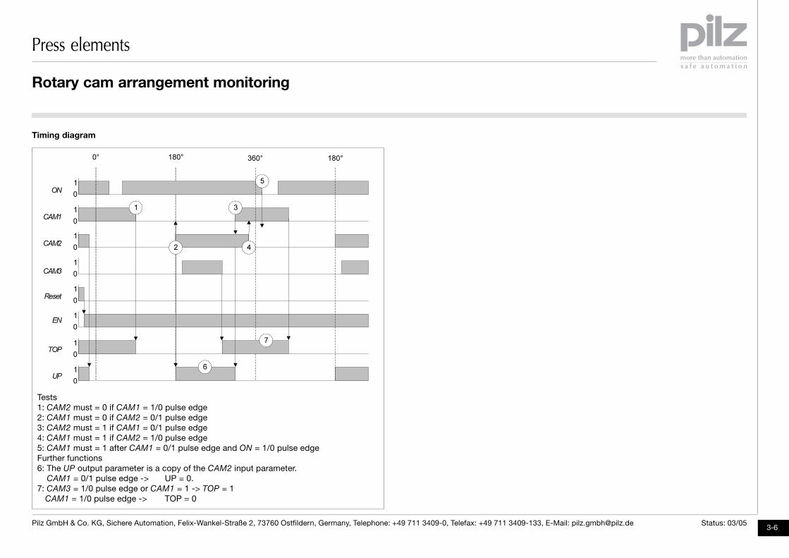
Tests1: CAM2 must = 0 if CAM1 = 1/0 pulse edge2: CAM1 must = 0 if CAM2 = 0/1 pulse edge3: CAM2 must = 1 if CAM1 = 0/1 pulse edge4: CAM1 must = 1 if CAM2 = 1/0 pulse edge5: CAM1 must = 1 after CAM1 = 0/1 pulse edge and ON = 1/0 pulse edgeFurther functions6: The UP output parameter is a copy of the CAM2 input parameter. CAM1 = 0/1 pulse edge -> UP = 0.7: CAM3 = 1/0 pulse edge or CAM1 = 1 -> TOP = 1
CAM1 = 1/0 pulse edge -> TOP = 0
Rotary cam arrangement monitoring

Press elements
3-7Pilz GmbH & Co. KG, Sichere Automation, Felix-Wankel-Straße 2, 73760 Ostfildern, Germany, Telephone: +49 711 3409-0, Telefax: +49 711 3409-133, E-Mail: [email protected] Status: 03/05
Function• Counts the number of interventions into
the protected field• MODE activates the element, enable
condition for press movement from Reset
(stroke 1) input parameter• Optional choice of Standard Mode or
Sweden Mode• Resets the logic element if the press is
not started within 30 seconds• Works in conjunction with the light curtain
function element
Input parameters• MODE
Activate logic elementMODE = 1: Light curtain press elementactivated, static conditionMODE = 0: Light curtain press elementnot activated, Enable output param-eter = 0
• LC
Output of light curtain function elementLC = 0: Protected field brokenLC = 1: Protected field clearThe cycle time counter counts the 0/1pulse edges for the enable. See Options
under Cycle mode.• TOP
Cycle resetTOP = 0/1 pulse edge: Resets theinternal cycle time counterAssign the TOP input parameter to theTOP output parameter of the rotary camarrangement monitoring press element.TOP = 0: During the hazardous down-ward movementTOP = 1: At top dead centre (TDC)
• UP
Run-up cam, press moves upwards.Assign to the UP output parameter of therotary cam arrangement monitoring presselement.
• Reset
Resets error messages, sets the operat-ing modeReset = 1/0 pulse edge: Trigger reset
Output parameters• Enable
Press stroke enableEnable = 1: The press stroke enable is setif the preselected number of interventionsis reached.TOP resets the enableEnable = 0: Press stroke enable not setAssign the Enable output parameterto the ON input parameter of the operat-ing modes logic element (single stroke).
Light curtain cycle mode Options• Operating mode: Standard Mode or
Sweden ModeThe procedure up to the enabling of thepress stroke is defined with the operatingmode.
• Intervention permitted during non-hazardous run-up:You can deactivate the option whichpermits an intervention into the protectedfield during the upward movement of thepress.
• Cycle modeThe light curtain press element (Enableoutput parameter) can be enabledvia repeated interruption of the ESPE/AOPD (cycle mode single break to5x break). The enable is cancelled viaa TOP = 0/1 pulse edge (e.g. at top deadcentre (TDC).
Diagnostic word• Bit 0: Module inactive• Bit 2: Waiting for acknowledgement• Bit 8: Waiting for cycle
Safety guidelines
CAUTION!• Guard mode
- The entire danger area must beblocked such that access to thedanger area is only possible throughthe light curtain.
- It must not be possible to access alight curtain from behind. It must not
Light curtain cycle mode
be possible to enter the room betweenthe light curtain and the danger area!
- If the light curtain is not polled in anoperating mode (e.g. in set-up mode),the power supply to the light curtainmust be switched off. The lamp at thelight curtain must not give a falseimpression of safety.
• Cycle mode- Standard mode: An intervention into
the protected field is first required forstart-up or for start-up after a restart.After the protected field has beencleared, the first start-up of the pressis triggered by a control device.
- Sweden mode: Actuation of thecontrol device first is required for start-up or for start-up after a restart. Thenan intervention into the protected fieldis required. Clearing the protectedfield triggers the first start-up of thepress.
- Only specific actuators such as two-hand buttons or separate buttons maybe used as control devices.
- Only 1-break or 2-break operation ispermitted at the presses. Higher cyclecounts are not permitted.
- If more than one light curtain isoperated at a press, the cycle modemay only be triggered via one lightcurtain. All other light curtains mustrun in guard mode.

Press elements
3-8Pilz GmbH & Co. KG, Sichere Automation, Felix-Wankel-Straße 2, 73760 Ostfildern, Germany, Telephone: +49 711 3409-0, Telefax: +49 711 3409-133, E-Mail: [email protected] Status: 03/05
- Cycle mode is only permitted undercertain constraints. According toEN 692: 1996, the following data mustbe maintained:The press table must be positioned atleast 750 mm above the standing areaof the operator.The initial stroke of the press must notexceed 600 mm.The depth of the press table must notexceed 1,000 mm.
Set-up operating mode set if MODE = 1, EN1 = 1 and EN2 = 1ON = 1/0 pulse edge: EN enable is reset
• TOP
Top dead centreTOP = 1: Press in the region of top deadcentreTOP = 0: Press not in the region of topdead centreTOP = 0/1 pulse edge: Enable is resetwhen single stroke protection is activatedAssign the output parameter TOP of therotary cam arrangement logic element tothe input parameter TOP.
• EN1
Static enableEN1 = 0: No static enableEN1 = 1: Static enableIf the press is moving then a "1" signalmust always be present at EN1. Thestatic enable is a logic AND connection ofthe enables from e.g. the E-STOP, start-up disabler, shearpin breakage, camshaft.
• EN2
Start enableEN2 = 0: No start enableEN2 = 1: Start enableA "1" signal must be present at EN2 if theON signal changes from "0" to "1". Thestart enable is a logic AND connection of the enables from e.g. the pressure monitor, motor.
• Reset
Resets error messagesReset = 1/0 pulse edge: Trigger reset
Light curtain cycle mode, set-up operating mode
Function• Configuration of set-up mode for a
mechanical press• Enabling of the press movement with the
input parameter ON provided the follow-ing conditions are satisfied:- Logic element is activated (MODE
input parameter)- Static enable EN1 is set- Start enable EN2 is set
• Stop the movement of the press withON = 0
• Operation with or without single strokeprotection
Input parameters• MODE
Activate/deactivate the logic element forthe set-up operating modeMODE = 1: Set-up operating modeactivated, static conditionMODE = 0: Set-up operating modedeactivated, Enable outputparameter = 0
• ON
Start signal for setting the enable (Enable output parameter)ON = 0/1 pulse edge: Start, Enable is

Press elements
3-9Pilz GmbH & Co. KG, Sichere Automation, Felix-Wankel-Straße 2, 73760 Ostfildern, Germany, Telephone: +49 711 3409-0, Telefax: +49 711 3409-133, E-Mail: [email protected] Status: 03/05
Output parameters• Enable
Enable for press movementEnable = 1: Enable is issued,- if ON = 0/1 pulse edge- and MODE = 1- and EN1 = 1- and EN2 = 1Enable = 0: Enable is not issued- if EN1 = 0- or MODE = 0- or TOP = 0/1 pulse edge (single stroke
protection)- or ON = 0- or EN2 = 0 (only required for start)Assign the Enable output parameter e.g.to the P_ON input parameter of the presssafety valve output element.
Options• Single stroke protection operation
You can configure the system so thatthere is no automatic stop at top deadcentre (TDC).
• Start enable operationYou can configure the system so that theEN2 start enable is deactivated and doesnot need to be connected.
Single stroke operating modeDiagnostic word• Bit 0: Module inactive• Bit 2: Waiting for acknowledgement• Bit 8: Start attempt, no start enable• Bit 9: Start attempt, no static enable• Bit 11: Operation, no static enable
Safety guidelines
CAUTION!Only the TOP output parameter of the rotarycam arrangement monitoring may beassigned to the TOP input parameter.
Function• Configuration of single stroke operating
mode for a mechanical press• Enabling of the press movement with the
ON input parameter, provided the follow-ing conditions are satisfied:- Logic element is activated (MODE
input parameter)- Static enable EN1 is set- Start enable EN2 is set- Safety enable EN3 is set
• Stop the movement of the press withON = 0
• Stop the movement of the press at topdead centre, TOP = 0/1 pulse edge
• Stop the movement of the press duringthe hazardous downward movement ifEN1 or EN3 = 0.
• Operation with or without enable signalduring upward movement of the press(overrides safety EN3 safety enable)
• Single stroke protection operation only
Input parameters• MODE
Activate/deactivate the logic element forthe single stroke operating mode
MODE = 1: Single stroke operating modeactivated, static conditionMODE = 0: Single stroke operating modedeactivated, Enable output parameter =0
• ON
Start signal for setting the enable (Enableoutput parameter)ON = 0/1 pulse edge: Start, enable is setif MODE = 1, EN1 = 1, EN2 = 1 andEN3 = 1ON = 1/0 pulse edge: Enable outputparameter is reset (during the downwardmovement before the enable signal)
• TOP
Top dead centreTOP = 1: Press in the region of top deadcentreTOP = 0: Press not in the region of topdead centreTOP = 0/1 pulse edge: Enable outputparameter is resetAssign the output parameter TOP of therotary cam arrangement logic element tothe input parameter TOP.
• UP
Enable signal, press moves upwards,overrides EN3
UP = 1: From bottom dead centre to thestart of the region of top dead centreAssign the output parameter UP of therotary cam arrangement logic element tothe input parameter UP. The press will runautomatically to top dead centre if it iscarrying out a safe movement (e.g. initialstroke).
Set-up operating mode, single stroke operating mode

Press elements
3-10Pilz GmbH & Co. KG, Sichere Automation, Felix-Wankel-Straße 2, 73760 Ostfildern, Germany, Telephone: +49 711 3409-0, Telefax: +49 711 3409-133, E-Mail: [email protected] Status: 03/05
• EN1
Static enableEN1 = 0: No static enableEN1 = 1: Static enableIf the press is moving then a "1" signalmust always be present at EN1. Thestatic enable is a logic AND connection ofthe enables from e.g. the E-STOP, start-up disabler, shearpin breakage, camshaft.
• EN2
Start enableEN2 = 0: No start enableEN2 = 1: Start enableA "1" signal must be present at EN2 if theON signal changes from "0" to "1". Thestart enable is a logic AND connection ofthe enables from e.g. the pressure monitor, motor.
• EN3
Safety enableEN3 = 0: No safety enableEN3 = 1: Safety enableA "1" signal must be present at EN3 if thepress is carrying out a hazardous move-ment. Assign the AND-linked enablesfrom e.g. the safety gate orelectrosensitive protective equipmentESPE/AOPD to the input parameter EN3.
• Reset
Resets error messagesReset = 1/0 pulse edge: Trigger reset
Output parameters• Enable
Enable for press movementEnable = 1: Enable is issued,- if ON = 0/1 pulse edge- and MODE = 1- and EN1 = 1- and EN2 = 1- and EN3 = 1Enable = 0: Enable is not issued,- if EN1 = 0- or MODE = 0- or TOP = 0/1 pulse edge (single stroke
protection)- or UP = 0 and (ON = 0 and EN3 = 0)- or EN2 = 0 (only required for start)Assign the Enable output parametere.g. to the P_ON input parameter of thepress safety valve output element.
Options• Run-up cam operation:
You can configure the system so that theEN3 safety enable is overridden duringthe upward movement of the press.
• Start enable operation:You can configure the system so that nospecial EN2 start enable is required.
• Safety enable operation:You can configure the system so that noEN3 prompt is effective.
Diagnostic word• Bit 0: Module inactive• Bit 2: Waiting for acknowledgement• Bit 8: Start attempt, no start enable• Bit 9: Start attempt, no static enable• Bit 10: Start attempt, no safety enable• Bit 11: Operation, no static enable• Bit 12: Operation, safety enable
Safety guidelines
CAUTION!• Only the TOP output parameter of the
rotary cam arrangement monitoring maybe assigned to the TOP input parameter.
• Only the UP output parameter of therotary cam arrangement monitoring maybe assigned to the UP input parameter.
Single stroke operating mode
Press elements
3-11Pilz GmbH & Co. KG, Sichere Automation, Felix-Wankel-Straße 2, 73760 Ostfildern, Germany, Telephone: +49 711 3409-0, Telefax: +49 711 3409-133, E-Mail: [email protected] Status: 03/05
Automatic operating mode
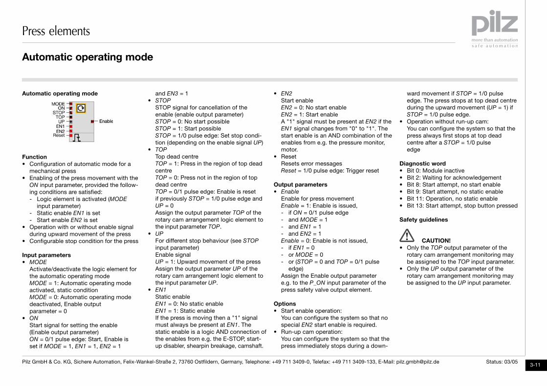
Function• Configuration of automatic mode for a
mechanical press• Enabling of the press movement with the
ON input parameter, provided the follow-ing conditions are satisfied:- Logic element is activated (MODE
input parameter)- Static enable EN1 is set- Start enable EN2 is set
• Operation with or without enable signalduring upward movement of the press
• Configurable stop condition for the press
Input parameters• MODE
Activate/deactivate the logic element forthe automatic operating modeMODE = 1: Automatic operating modeactivated, static conditionMODE = 0: Automatic operating modedeactivated, Enable outputparameter = 0
• ON
Start signal for setting the enable (Enable output parameter)ON = 0/1 pulse edge: Start, Enable isset if MODE = 1, EN1 = 1, EN2 = 1
and EN3 = 1• STOP
STOP signal for cancellation of theenable (enable output parameter)STOP = 0: No start possibleSTOP = 1: Start possibleSTOP = 1/0 pulse edge: Set stop condi-tion (depending on the enable signal UP)
• TOP
Top dead centreTOP = 1: Press in the region of top deadcentreTOP = 0: Press not in the region of topdead centreTOP = 0/1 pulse edge: Enable is resetif previously STOP = 1/0 pulse edge andUP = 0Assign the output parameter TOP of therotary cam arrangement logic element tothe input parameter TOP.
• UP
For different stop behaviour (see STOP
input parameter)Enable signalUP = 1: Upward movement of the pressAssign the output parameter UP of therotary cam arrangement logic element tothe input parameter UP.
• EN1
Static enableEN1 = 0: No static enableEN1 = 1: Static enableIf the press is moving then a "1" signalmust always be present at EN1. Thestatic enable is a logic AND connection of the enables from e.g. the E-STOP , start-up disabler, shearpin breakage, camshaft.
• EN2
Start enableEN2 = 0: No start enableEN2 = 1: Start enableA "1" signal must be present at EN2 if theEN1 signal changes from "0" to "1". Thestart enable is an AND combination of theenables from e.g. the pressure monitor,motor.
• ResetResets error messagesReset = 1/0 pulse edge: Trigger reset
Output parameters• Enable
Enable for press movementEnable = 1: Enable is issued,- if ON = 0/1 pulse edge- and MODE = 1- and EN1 = 1- and EN2 = 1Enable = 0: Enable is not issued,- if EN1 = 0- or MODE = 0- or (STOP = 0 and TOP = 0/1 pulse
edge)Assign the Enable output parametere.g. to the P_ON input parameter of thepress safety valve output element.
Options• Start enable operation:
You can configure the system so that nospecial EN2 start enable is required.
• Run-up cam operation:You can configure the system so that thepress immediately stops during a down-
ward movement if STOP = 1/0 pulseedge. The press stops at top dead centreduring the upward movement (UP = 1) ifSTOP = 1/0 pulse edge.
• Operation without run-up cam:You can configure the system so that thepress always first stops at top deadcentre after a STOP = 1/0 pulseedge
Diagnostic word• Bit 0: Module inactive• Bit 2: Waiting for acknowledgement• Bit 8: Start attempt, no start enable• Bit 9: Start attempt, no static enable• Bit 11: Operation, no static enable• Bit 13: Start attempt, stop button pressed
Safety guidelines
CAUTION!• Only the TOP output parameter of the
rotary cam arrangement monitoring maybe assigned to the TOP input parameter.
• Only the UP output parameter of therotary cam arrangement monitoring maybe assigned to the UP input parameter.
Automatic operating mode

Press elements
3-12Pilz GmbH & Co. KG, Sichere Automation, Felix-Wankel-Straße 2, 73760 Ostfildern, Germany, Telephone: +49 711 3409-0, Telefax: +49 711 3409-133, E-Mail: [email protected] Status: 03/05
Press Safety Valves
Single valve
Input parameters• P_ON1
Start input, switches valve 1 on and offP_ON1 = 0/1 pulse edge: Switching onP_ON1 = 1/0 pulse edge: Switching off
• P_ON2 (for directional valve only)Start input, switches valve 2 on and offP_ON2 = 0/1 pulse edge: Switching onP_ON2 = 1/0 pulse edge: Switching off
• FB1
Feedback loop for valve 1• FB2 (for double or directional valve only)
Feedback loop for valve 2• Reset
Resets error messagesReset = 1/0 pulse edge: Trigger reset
Output parameters• Valve outputs for single or dual-pole
single, double or directional valve
Options• Output type:
You can choose between single-poleoutputs and dual-pole outputs.
NOTICEConfigure dual-pole outputs forcontrolling the press safety valves
Double valve
Directional valve
Function• Controlling and monitoring of single,
double and directional valves• Different times can be set for power-up
and switch-off monitoring• Actuation of indirectly controlled valves is
possible
Press safety valves
• Monitor feedback loop for controlledvalve:You can configure the system so that thefeedback loop is monitored while thevalve is being controlled.
• Power-up monitoring/switch-off monitoring:- TOn power-up monitoring
Permitted value range: 50 ... 3000 ms- TOff power-off monitoring
Permitted value range: 50 ... 3000 ms
Diagnostic word• Bit 0: Module inactive, output not
controlled• Bit 2: Waiting for acknowledgement• Bit 8: Start attempt when feedback
loop open• Bit 11: TOn exceeded• Bit 12: TOff exceeded• Bit 13: Feedback loop closes when
valve is driven

Example
4-1Pilz GmbH & Co. KG, Sichere Automation, Felix-Wankel-Straße 2, 73760 Ostfildern, Germany, Telephone: +49 711 3409-0, Telefax: +49 711 3409-133, E-Mail: [email protected] Status: 03/05
IntroductionThe following example demonstrates theinteraction of the press elements in acomplete application.The example shows the principle design ofa program for mechanical presses in thePNOZmulti Configurator. The correspondingadaptations must, of course, be made forindividual cases.
The modular concept of the PNOZmultiConfigurator provides the user with a highdegree of flexibility. Certain requirementsalso are placed on the creator of pressapplications. Exact knowledge of theoperation of the press as well as knowledgeof the respective standards are absoluterequirements.Once the application has been created, itsoperation must be thoroughly tested at thepress. This test should be repeated by asecond competent person.
The example application has the followingstructure:• Rotary cam arrangement monitoring• Poll safety devices• Poll control devices• Forming enables• Monitor and poll operating mode
selector switch• Use light curtain as control device (cycle
mode)• Set-up operating mode
• Single stroke operating mode• Automatic operating mode• Control press safety valve• Signal lamps, diagnostics
CAUTION!When an operating mode is selectedvia the operating mode selectorswitch, only one element for therespective operating mode may beactivated (MODE input parameter).
Example project on CDYou will find the"Mech_Press_Sample.mpnoz" exampleproject on the CD. You must enter a pass-word in order to open the project. Thepassword is: 1
Hardware configuration
Introduction
Project name: Mech_Press_Sample.mpnoz
PNOZmulti ReportHardware configuration
ID123
Module namePNOZ m2p base module for pressesPNOZ mi1p input modulePNOZ mo3p dual-pole semiconductor output module
Versionv1.0.0v1.0v1.0
Equipment identifierA1A2A3
Inputs2080
Outputs602
Example
2
4-2Pilz GmbH & Co. KG, Sichere Automation, Felix-Wankel-Straße 2, 73760 Ostfildern, Germany, Telephone: +49 711 3409-0, Telefax: +49 711 3409-133, E-Mail: [email protected] Status: 03/05
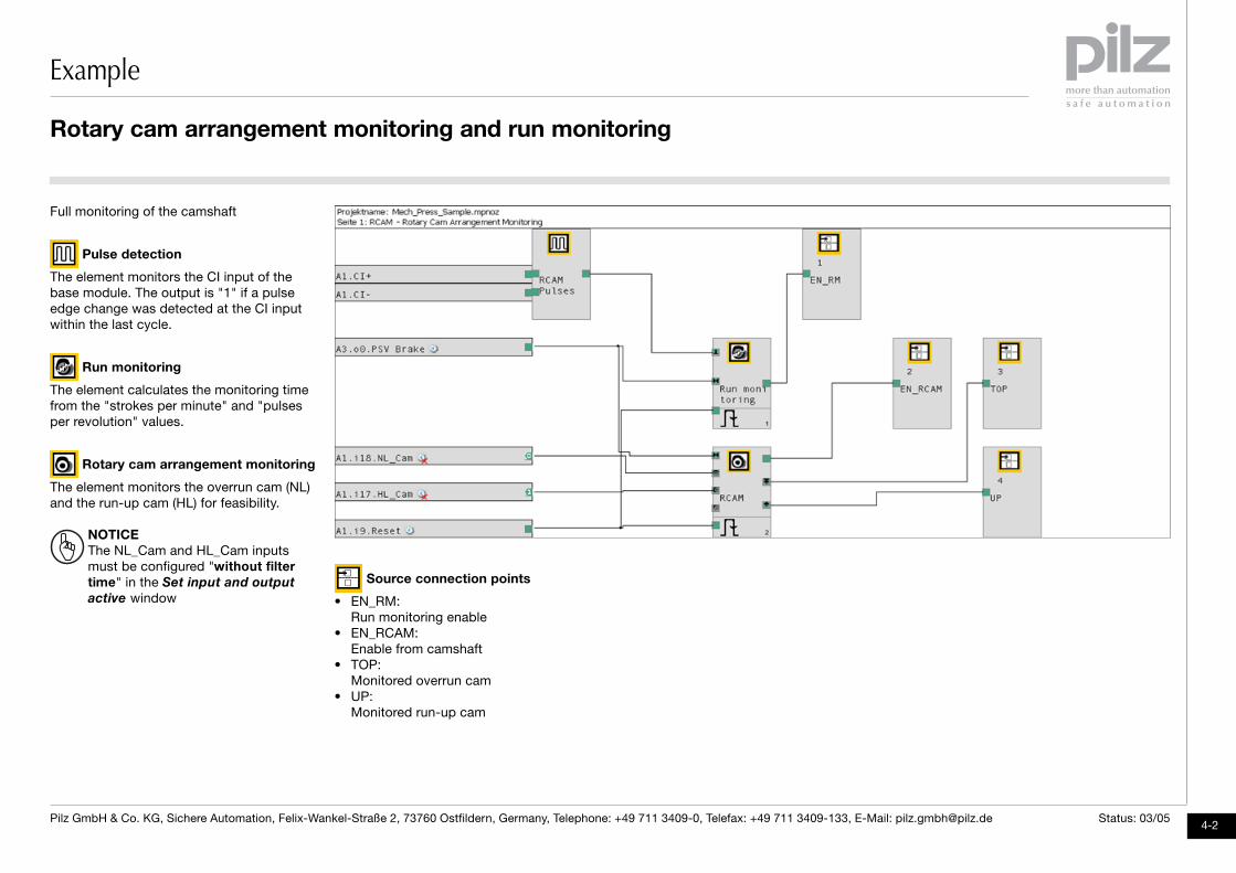
Full monitoring of the camshaft
Pulse detection
The element monitors the CI input of thebase module. The output is "1" if a pulseedge change was detected at the CI inputwithin the last cycle.
Run monitoring
The element calculates the monitoring timefrom the "strokes per minute" and "pulsesper revolution" values.
Rotary cam arrangement monitoring
The element monitors the overrun cam (NL)and the run-up cam (HL) for feasibility.
NOTICEThe NL_Cam and HL_Cam inputsmust be configured "without filter
time" in the Set input and output
active window
Source connection points
• EN_RM:Run monitoring enable
• EN_RCAM:Enable from camshaft
• TOP:Monitored overrun cam
• UP:Monitored run-up cam
Rotary cam arrangement monitoring and run monitoring
Example
4-3Pilz GmbH & Co. KG, Sichere Automation, Felix-Wankel-Straße 2, 73760 Ostfildern, Germany, Telephone: +49 711 3409-0, Telefax: +49 711 3409-133, E-Mail: [email protected] Status: 03/05
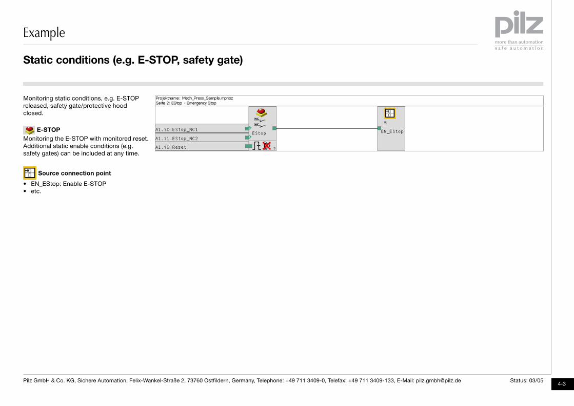
Monitoring static conditions, e.g. E-STOPreleased, safety gate/protective hoodclosed.
E-STOPMonitoring the E-STOP with monitored reset.Additional static enable conditions (e.g.safety gates) can be included at any time.
Source connection point
• EN_EStop: Enable E-STOP• etc.
Static conditions (e.g. E-STOP, safety gate)
Example
2
4-4Pilz GmbH & Co. KG, Sichere Automation, Felix-Wankel-Straße 2, 73760 Ostfildern, Germany, Telephone: +49 711 3409-0, Telefax: +49 711 3409-133, E-Mail: [email protected] Status: 03/05
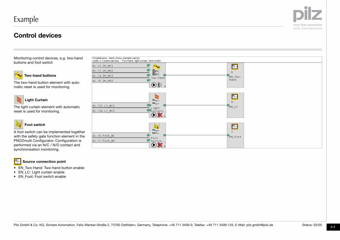
Monitoring control devices, e.g. two-handbuttons and foot switch
Two-hand buttons
The two-hand button element with auto-matic reset is used for monitoring.
Light Curtain
The light curtain element with automaticreset is used for monitoring.
Foot switch
A foot switch can be implemented togetherwith the safety gate function element in thePNOZmulti Configurator. Configuration isperformed via an N/C / N/O contact andsynchronisation monitoring.
Source connection point
• EN_Two-Hand: Two-hand button enable• EN_LC: Light curtain enable• EN_Foot: Foot switch enable
Control devices
Example
4-5Pilz GmbH & Co. KG, Sichere Automation, Felix-Wankel-Straße 2, 73760 Ostfildern, Germany, Telephone: +49 711 3409-0, Telefax: + 49 711 3409-133, E-Mail: [email protected] Status: 03/05
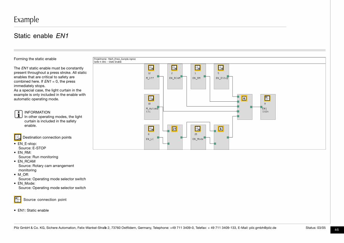
Forming the static enable
The EN1 static enable must be constantlypresent throughout a press stroke. All staticenables that are critical to safety arecombined here. If EN1 = 0, the pressimmediately stops.As a special case, the light curtain in theexample is only included in the enable withautomatic operating mode.
INFORMATIONIn other operating modes, the lightcurtain is included in the safetyenable.
Destination connection points
• EN_E-stop:Source: E-STOP
• EN_RM:Source: Run monitoring
• EN_RCAMSource: Rotary cam arrangementmonitoring
• M_Off:Source: Operating mode selector switch
• EN_Mode:Source: Operating mode selector switch
Source connection point
• EN1: Static enable
Static enable EN1

Example
2
4-6Pilz GmbH & Co. KG, Sichere Automation, Felix-Wankel-Straße 2, 73760 Ostfildern, Germany, Telephone: +49 711 3409-0, Telefax: +49 711 3409-133, E-Mail: [email protected] Status: 03/05
Forming the start enable and the safetyenable
EN2 Start enableThe EN2 start enable must only be presentwhen the press stroke is triggered. Duringthe press movement, EN2 can = 0.
EN3 Safety enableThe EN3 safety enable must be presentduring the hazardous downward movementof the press. In the upward movement, EN3
can be overridden by the run-up cam if noother hazards exist (e.g. via ejectors).
Destination connection point
• EN_LC:Source: Light Curtain
Source connection points
• EN2 SrEn: Start enable• EN3 SaEn: Safety enable
Start enable EN2 and safety enable EN3
Example
4-7Pilz GmbH & Co. KG, Sichere Automation, Felix-Wankel-Straße 2, 73760 Ostfildern, Germany, Telephone: +49 711 3409-0, Telefax: +49 711 3409-133, E-Mail: [email protected] Status: 03/05
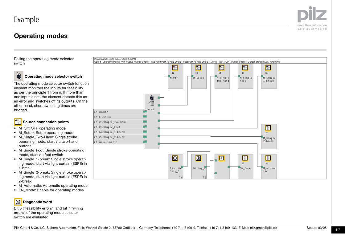
Polling the operating mode selectorswitch
Operating mode selector switch
The operating mode selector switch functionelement monitors the inputs for feasibilityas per the principle 1 from n. If more than one input is set, the element detects this as an error and switches off its outputs. On theother hand, short switching times arebridged.
Source connection points
• M_Off: OFF operating mode• M_Setup: Setup operating mode• M_Single_Two-Hand: Single stroke
operating mode, start via two-handbuttons
• M_Single_Foot: Single stroke operatingmode, start via foot switch
• M_Single_1-break: Single stroke operat-ing mode, start via light curtain (ESPE) in1-break
• M_Single_2-break: Single stroke operat-ing mode, start via light curtain (ESPE) in2-break
• M_Automatic: Automatic operating mode• EN_Mode: Enable for operating modes
Diagnostic word
Bit 5 ("feasibility errors") and bit 7 "wiringerrors" of the operating mode selectorswitch are evaluated.
Operating modes
Example
2
4-8Pilz GmbH & Co. KG, Sichere Automation, Felix-Wankel-Straße 2, 73760 Ostfildern, Germany, Telephone: +49 711 3409-0, Telefax: + 49 711 3409-133, E-Mail: [email protected] Status: 03/05
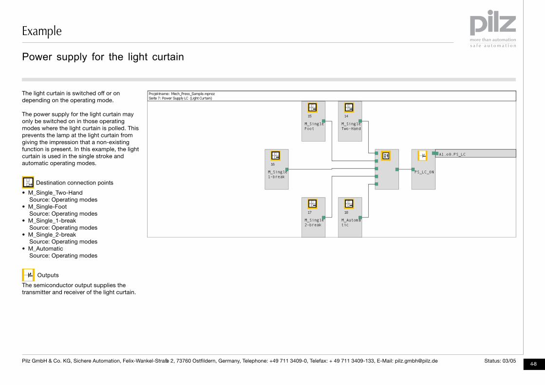
The light curtain is switched off or ondepending on the operating mode.
The power supply for the light curtain mayonly be switched on in those operatingmodes where the light curtain is polled. Thisprevents the lamp at the light curtain fromgiving the impression that a non-existingfunction is present. In this example, the lightcurtain is used in the single stroke andautomatic operating modes.
Destination connection points
• M_Single_Two-HandSource: Operating modes
• M_Single-FootSource: Operating modes
• M_Single_1-breakSource: Operating modes
• M_Single_2-breakSource: Operating modes
• M_AutomaticSource: Operating modes
Outputs
The semiconductor output supplies thetransmitter and receiver of the light curtain.
Power supply for the light curtain
Example
4-9Pilz GmbH & Co. KG, Sichere Automation, Felix-Wankel-Straße 2, 73760 Ostfildern, Germany, Telephone: +49 711 3409-0, Telefax: + 49 711 3409-133, E-Mail: [email protected] Status: 03/05
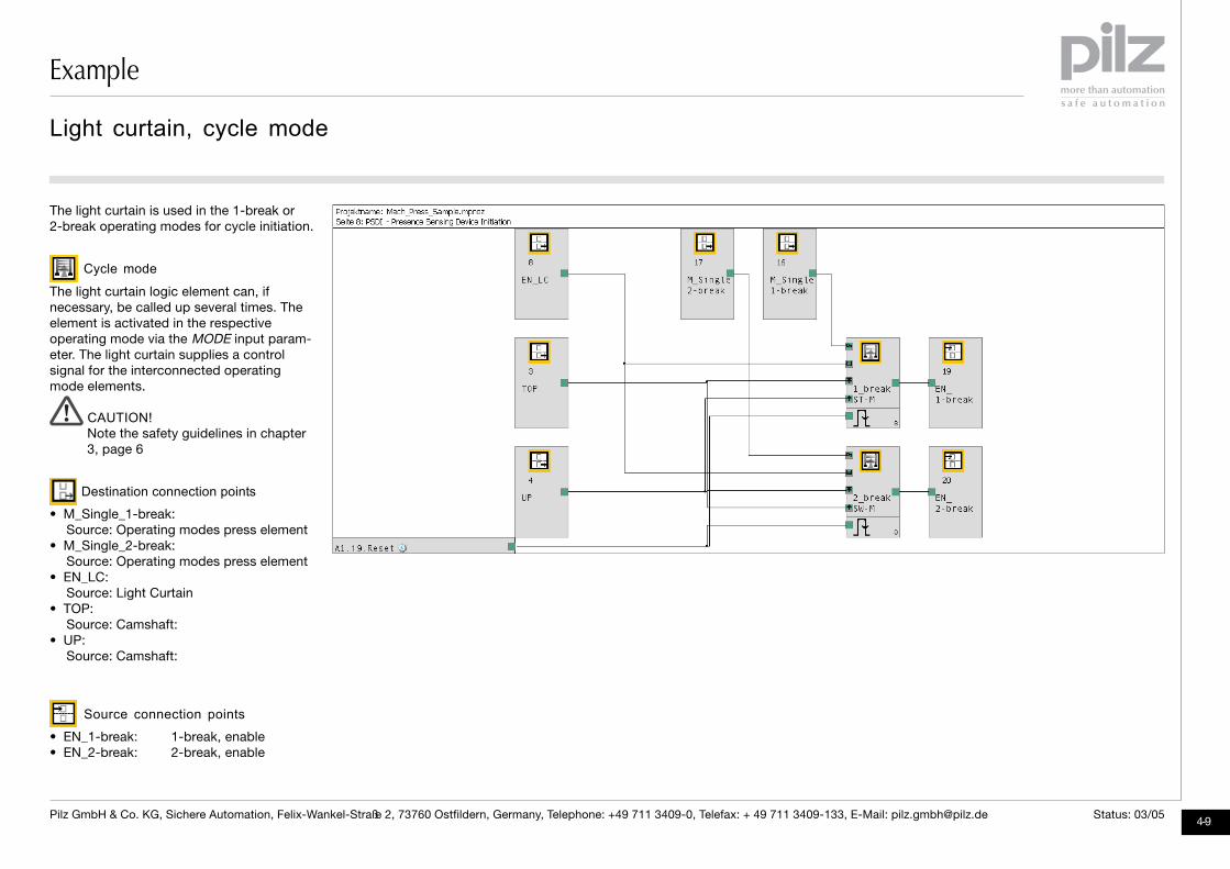
The light curtain is used in the 1-break or2-break operating modes for cycle initiation.
Cycle mode
The light curtain logic element can, ifnecessary, be called up several times. Theelement is activated in the respectiveoperating mode via the MODE input param-eter. The light curtain supplies a controlsignal for the interconnected operatingmode elements.
CAUTION!Note the safety guidelines in chapter3, page 6
Destination connection points
• M_Single_1-break:Source: Operating modes press element
• M_Single_2-break:Source: Operating modes press element
• EN_LC:Source: Light Curtain
• TOP:Source: Camshaft:
• UP:Source: Camshaft:
Source connection points
• EN_1-break: 1-break, enable• EN_2-break: 2-break, enable
Light curtain, cycle mode

Example
2
4-10Pilz GmbH & Co. KG, Sichere Automation, Felix-Wankel-Straße 2, 73760 Ostfildern, Germany, Telephone: +49 711 3409-0, Telefax: + 49 711 3409-133, E-Mail: [email protected] Status: 03/05
Executing the setup operating mode
Operating mode: Setup
The logic element is only active in the setupoperating mode if the MODE input parameteris set. The two-hand button is connected tothe ON input parameter as a control device.The logic element is configured with singlestroke protection. Another possibility wouldbe a configuration without automatic stop attop dead centre (TDC).
Destination connection points
• M_Setup:Source: Operating modes logic element
• EN_Two-Hand:Source: Two-hand button functionelement
• TOP:Source: Rotary cam arrangement moni-toring
• EN1 StEn:Source: Static enable
• En2 SrEn:Source: Start enable
Source connection point
• P_ON_Setup: Press ON in setup mode
Setup operating mode

Example
4-11Pilz GmbH & Co. KG, Sichere Automation, Felix-Wankel-Straße 2, 73760 Ostfildern, Germany, Telephone: +49 711 3409-0, Telefax: + 49 711 3409-133, E-Mail: [email protected] Status: 03/05
The initial stroke in the single stroke operat-ing mode should occur from top deadcentre (TDC) via a two-hand button. Theoperating mode is only active if the press isin the top dead centre (TDC) position.
Destination connection points
• TOP:Source: Rotary cam arrangementmonitoring
• M_Single_Two-Hand:Source: Single stroke operating mode,start via two-hand button
Source connection point
• M_Single_2H_TDC: Operating mode attop dead centre (TDC) selected
Single stroke operating mode, start via two-hand button at top dead centre

Example
2
4-12Pilz GmbH & Co. KG, Sichere Automation, Felix-Wankel-Straße 2, 73760 Ostfildern, Germany, Telephone: +49 711 3409-0, Telefax: + 49 711 3409-133, E-Mail: [email protected] Status: 03/05
Executing single stroke operating mode,start via two-hand button.
Operating mode: Single stroke, start
via two-hand buttonThe single stroke logic element is activewhen the operating mode is set by theMODE input parameter. The two-handbutton is connected to the ON input param-eter as a control device. The element alwaysoperates with single stroke protection. Theelement is configured with enable in run-up.The user is protected by the safety enableduring the downward movement.
Destination connection points
• M_Single_2H_TDC:Source: Operating modes logic elementand top dead centre (TDC)
• EN_Two-Hand:Source: Two-hand button functionelement
• TOP:Source: Rotary cam arrangementmonitoring
• UP:Source: Rotary cam arrangementmonitoring
• EN1 StEn:Source: Static enable
• EN2 SrEn:Source: Start enable
• EN3 SaEn:Source: Safety enable
Single stroke operating mode, start via two-hand button
Source connection point
• P_ON-Two-hand: Press ON, single strokeoperating mode, two-hand button
Example
4-13Pilz GmbH & Co. KG, Sichere Automation, Felix-Wankel-Straße 2, 73760 Ostfildern, Germany, Telephone: +49 711 3409-0, Telefax: + 49 711 3409-133, E-Mail: [email protected] Status: 03/05
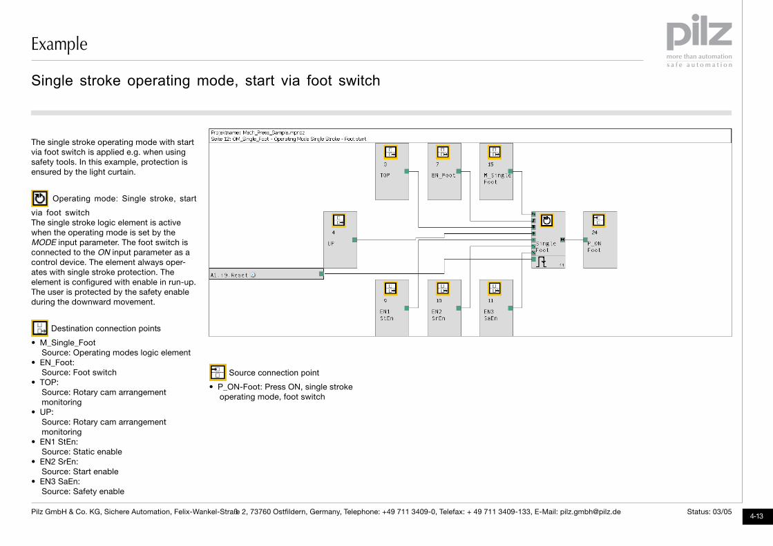
The single stroke operating mode with startvia foot switch is applied e.g. when usingsafety tools. In this example, protection isensured by the light curtain.
Operating mode: Single stroke, start
via foot switchThe single stroke logic element is activewhen the operating mode is set by theMODE input parameter. The foot switch isconnected to the ON input parameter as acontrol device. The element always oper-ates with single stroke protection. Theelement is configured with enable in run-up.The user is protected by the safety enableduring the downward movement.
Destination connection points
• M_Single_FootSource: Operating modes logic element
• EN_Foot:Source: Foot switch
• TOP:Source: Rotary cam arrangementmonitoring
• UP:Source: Rotary cam arrangementmonitoring
• EN1 StEn:Source: Static enable
• EN2 SrEn:Source: Start enable
• EN3 SaEn:Source: Safety enable
Source connection point
• P_ON-Foot: Press ON, single strokeoperating mode, foot switch
Single stroke operating mode, start via foot switch

Example
2
4-14Pilz GmbH & Co. KG, Sichere Automation, Felix-Wankel-Straße 2, 73760 Ostfildern, Germany, Telephone: +49 711 3409-0, Telefax: + 49 711 3409-133, E-Mail: [email protected] Status: 03/05
Single stroke operating mode, light curtain, 1-break
Execution of the single stroke operatingmode, start via signal from light curtain logicelement (1-break).
Operating mode: Single stroke, start
via light curtain logic element (cycle mode)The single stroke logic element is activewhen the operating mode is set by the MODEinput parameter. The signal at the ON inputparameter comes from the light curtain logicelement (1-break). The element alwaysoperates with single stroke protection. Theelement is configured with enable in run-up.The user is protected by the safety enableduring the downward movement.
Destination connection points
• M_Single_1-breakSource: Operating modes logic element
• EN_1-break:Source: Light curtain logic element(1-break)
• TOP:Source: Rotary cam arrangementmonitoring
• UP:Source: Rotary cam arrangementmonitoring
• EN1 StEn:Source: Static enable
• EN2 SrEn:Source: Start enable
• EN3 SaEn:Source: Safety enable
Source connection point
• P_ON-1-break: Press ON, single strokeoperating mode, 1-break
Example
4-15Pilz GmbH & Co. KG, Sichere Automation, Felix-Wankel-Straße 2, 73760 Ostfildern, Germany, Telephone: +49 711 3409-0, Telefax: + 49 711 3409-133, E-Mail: [email protected] Status: 03/05
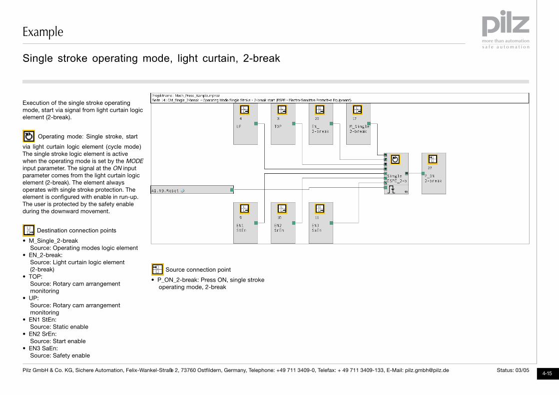
Execution of the single stroke operatingmode, start via signal from light curtain logicelement (2-break).
Operating mode: Single stroke, start
via light curtain logic element (cycle mode)The single stroke logic element is activewhen the operating mode is set by the MODEinput parameter. The signal at the ON inputparameter comes from the light curtain logicelement (2-break). The element alwaysoperates with single stroke protection. Theelement is configured with enable in run-up.The user is protected by the safety enableduring the downward movement.
Destination connection points
• M_Single_2-breakSource: Operating modes logic element
• EN_2-break:Source: Light curtain logic element(2-break)
• TOP:Source: Rotary cam arrangementmonitoring
• UP:Source: Rotary cam arrangementmonitoring
• EN1 StEn:Source: Static enable
• EN2 SrEn:Source: Start enable
• EN3 SaEn:Source: Safety enable
Source connection point
• P_ON_2-break: Press ON, single strokeoperating mode, 2-break
Single stroke operating mode, light curtain, 2-break
Example
2
4-16Pilz GmbH & Co. KG, Sichere Automation, Felix-Wankel-Straße 2, 73760 Ostfildern, Germany, Telephone: +49 711 3409-0, Telefax: + 49 711 3409-133, E-Mail: [email protected] Status: 03/05
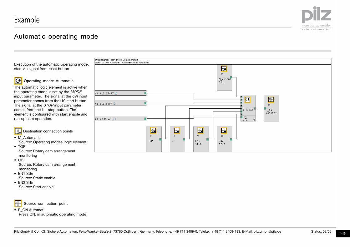
Execution of the automatic operating mode,start via signal from reset button
Operating mode: Automatic
The automatic logic element is active whenthe operating mode is set by the MODEinput parameter. The signal at the ON inputparameter comes from the i10 start button.The signal at the STOP input parametercomes from the i11 stop button. Theelement is configured with start enable andrun-up cam operation.
Destination connection points
• M_AutomaticSource: Operating modes logic element
• TOPSource: Rotary cam arrangementmonitoring
• UPSource: Rotary cam arrangementmonitoring
• EN1 StEnSource: Static enable
• EN2 SrEnSource: Start enable
Source connection point
• P_ON Automat:Press ON, in automatic operating mode
Automatic operating mode

Example
4-17Pilz GmbH & Co. KG, Sichere Automation, Felix-Wankel-Straße 2, 73760 Ostfildern, Germany, Telephone: +49 711 3409-0, Telefax: + 49 711 3409-133, E-Mail: [email protected] Status: 03/05
Valve control
The press safety valve is controlled by theOR-linked outputs of the operating modelogic elements
Destination connection points
• P_ON SetupSource: Setup operating mode
• P_ON Two-handSource: Single stroke operating mode,start via two-hand button
• P_ON FootSource: Single stroke operating mode,start via foot switch
• P_ON 1-breakSource: Single stroke operating mode,start via light curtain (1-break)
• P_ON 2-breakSource: Single stroke operating mode,start via light curtain (2-break)
• P_ON AutomatSource: Automatic operating mode
Outputs
Direct control of PSV press safety valveswith PNOZ mo3p dual-pole semiconductoroutputs.
Controlling the press safety valve

Example
2
4-18Pilz GmbH & Co. KG, Sichere Automation, Felix-Wankel-Straße 2, 73760 Ostfildern, Germany, Telephone: +49 711 3409-0, Telefax: + 49 711 3409-133, E-Mail: [email protected] Status: 03/05
Displaying the “Waiting for acknowledgement” diagnostic word
Diagnostic word
Bit 2 of the diagnostic word is evaluated forthe elements: "Waiting for acknowledge-ment". If the element is waiting for anacknowledgement, the output of the diag-nostic word logic element is set.
Outputs
The semiconductor output can, for example,control an LED.

Example
4-19Pilz GmbH & Co. KG, Sichere Automation, Felix-Wankel-Straße 2, 73760 Ostfildern, Germany, Telephone: +49 711 3409-0, Telefax: +49 711 3409-133, E-Mail: [email protected] Status: 03/05
Displaying the diagnostic word for light curtains
Diagnostic word
Various information is evaluated in thediagnostic word for the light curtain logicelements.The output of the diagnostic word logicelement is set if the light curtain is inter-rupted or an intervention into the protectedfield is expected.
Outputs
The information is signalled via two semi-conductor outputs.

4-20Pilz GmbH & Co. KG, Sichere Automation, Felix-Wankel-Straße 2, 73760 Ostfildern, Germany, Telephone: +49 711 3409-0, Telefax: +49 711 3409-133, E-Mail: [email protected] Status: 03/05

P
CH
D
DK
E
F
FIN
GB
I
IRL
J
MEX
NL
NZ
PRC
ROK
SE
TR
A
AUS
B ��L
BR
... www
USA
Pilz Ges.m.b.H.Modecenterstraße 141030 WienAustriaTelephone: 01 7986263-0Telefax: 01 7986264E-Mail: [email protected]
Pilz AustraliaIndustrial Automation LP.9/475 Blackburn RoadMt. Waverley, Melbourne VIC 3149AustraliaTelephone: 03 95446300Telefax: 03 95446311E-Mail: [email protected]
Pilz BelgiumBijenstraat 49051 Gent (Sint-Denijs-Westrem)BelgiumTelephone: 09 3217570Telefax: 09 3217571E-Mail: [email protected]
Pilz do Brasil Sistemas EletrônicosIndustriais Ltda.Rua Ártico, 123 - Jd. do Mar09726-300São Bernardo do Campo - SPBrazilTelephone: 11 4337-1241Telefax: 11 4337-1242E-Mail: [email protected]
Pilz lndustrieelektronik GmbHGewerbepark HintermättliPostfach 65506 MägenwilSwitzerlandTelephone: 062 88979-30Telefax: 062 88979-40E-Mail: [email protected]
Pilz GmbH & Co. KGSichere AutomationFelix-Wankel-Straße 273760 OstfildernGermanyTelephone: 0711 3409-0Telefax: 0711 3409-133E-Mail: [email protected]
Pilz Skandinavien K/SEllegaardvej 25 L6400 SonderborgDenmarkTelephone: 74436332Telefax: 74436342E-Mail: [email protected]
Pilz lndustrieelektronik S.L.Camí Ral, 130Polígono Industrial Palou Nord08400 GranollersSpainTelephone: 938497433Telefax: 938497544E-Mail: [email protected]
Pilz France Electronic1, rue Jacob MayerBP 1267037 Strasbourg CedexFranceTelephone: 03 88104000Telefax: 03 88108000E-Mail: [email protected]
Pilz Skandinavien K/SPakilantie 6100660 HelsinkiFinlandTelephone: 09 27093700Telefax: 09 27093709E-Mail: [email protected]
Pilz Automation TechnologyWillow House, Medlicott CloseOakley Hay Business ParkCorbyNorthants NN18 9NFUnited KingdomTelephone: 01536 460766Telefax: 01536 460866E-Mail: [email protected]
Pilz ltalia SrlVia Meda 2/A22060 Novedrate (CO)ItalyTelephone: 031 789511Telefax: 031 789555E-Mail: [email protected]
Pilz Ireland Industrial AutomationCork Business and Technology ParkModel Farm RoadCorkIrelandTelephone: 021 4346535Telefax: 021 4804994E-Mail: [email protected]
Pilz Japan Co., Ltd.Shin-Yokohama Fujika Building 5F2-5-9 Shin-YokohamaKohoku-kuYokohama 222-0033JapanTelephone: 045 471-2281Telefax: 045 471-2283E-Mail: [email protected]
Pilz de Mexico, S. de R.L. de C.V.Circuito Pintores # 170Cd. SateliteC.P. 53100Naucalpan de Juarez, Edo. de MexicoMexicoTelephone: 55 5572 1300Telefax: 55 5572 4194E-Mail: [email protected]
Pilz NederlandPostbus 1864130 ED VianenNetherlandsTelephone: 0347 320477Telefax: 0347 320485E-Mail: [email protected]
Pilz New Zealand3 Kohanga RoadManagere BridgeAucklandNew ZealandTelephone: 09-6345350Telefax: 09-6345350E-Mail: [email protected]
Pilz Industrieelektronik S.L.R. Eng Duarte Pacheco, 1204 Andar Sala 214470-174 MaiaPortugalTelephone: 229407594Telefax: 229407595E-Mail: [email protected]
Pilz China Representative OfficeRm. 302No. 88 Chang Shu RoadShanghai 200040ChinaTelephone: 021 62493031Telefax: 021 62493036E-Mail: [email protected]
Pilz Korea Office402 Samsung Midas Officetel775-1, Janghang-Dong,Ilsan-Gu, Koyang-SiKyungki-Do 411-837KoreaTelephone: 031 8159541Telefax: 031 8159542E-Mail: [email protected]
In many countries we arerepresented by sales partners.
Please refer to our Homepagefor further details or contact ourheadquarters.
www.pilz.com
Pilz GmbH & Co. KGSichere AutomationFelix-Wankel-Straße 273760 Ostfildern, GermanyTelephone: +49 711 3409-0Telefax: +49 711 3409-133E-Mail: [email protected] A
uto
mat
ion
Wo
rkb
ench
®,
Pilz
®,
PM
I®,
PN
OZ
®,
PS
S®,
Saf
etyB
US
p® a
re r
egis
tere
d t
rad
emar
ks o
f P
ilz G
mb
H &
Co
. K
G.
Text
and
gra
phi
cs in
thi
s ap
plic
atio
n m
anua
l are
sim
ply
inte
nded
to
giv
e an
ove
rvie
w o
f th
e sy
stem
.N
o r
esp
ons
ibili
ty a
ccep
ted
fo
r er
rors
or
om
issi
ons
.
Pilz Skandinavien K/SEnergigatan 10 B43437 KungsbackaSwedenTelephone: 0300 13990Telefax: 0300 30740E-Mail: [email protected]
Pilz Elektronik Güvenlik Ürünlerive Hizmetleri Tic. Ltd. †ti.Tan i‡ MerkeziKükürtlü Caddesi No: 67C-Blok Daire: 116080 BursaTurkeyTelephone:0224 2360180Telefax: 0224 2360184E-Mail: [email protected]
Pilz Automation Safety L.P.7150 Commerce BoulevardCantonMichigan 48187USATelephone: 734 354-0272Telefax: 734 354-3355E-Mail: [email protected]
21 0
55-0
1-03
/05
Pri
nted
in G
erm
any