pneumatically operated 2/2-way angle seat valve with
TRANSCRIPT

2060
S. 1/12www.burkert.com
Pneumatically operated 2/2-way angle seat valve with stainless steel actuator
The pneumatically operated angle seat
valve with stainless steel actuators fulfi ls the
demands of tough process environments.
Unrivalled cycle life and sealing integrity is
guaranteed by the trusted self-adjusting
spindle packing with V-seals.
The stainless steel actuator is designed to
withstand tough conditions. Laser welding
allows a design without seals and smooth sur-
faces that is both cleanable and robust. With
a ducted exhaust air port the actuator can be
isolated from the environment an optimum
from a lifetime and hygienic point of view.
High fl ow rates are attained with the optimized
cast stainless steel 2 way body. Placed within
the Bürkert process valves various port con-
nections and a large accessory program are
available.
All wetted parts comply with the EC-Regulation
1935/2004, variants with FDA conformity are
available on request, also explosion proof
variants are available.
Type 2060 Welded can be combined with...
• Flow optimized stainless steel bodies with various port connections
• Trusted inner parts for long cycle life
• Actuator in stainless steel for demanding environments
• Large accessory program with stroke limitation and feedback
Content
Valve specifi cations System spec. On/Off ELEMENT Request for quotation
Type 2060 Type 8801-YE Type 8801-YE
Technical data & ordering info. p. 1-4 Technical data & ordering info. p. 9 p. 11
Type 8697
feedback
Stroke limiter
Technical data
Orifi ce DN15 to DN65; 1/2" to 2 1/2"
Port connections
Welded acc. to
Clamp and threaded
DIN EN ISO 1127/ISO 4200/DIN 11866 series B
DIN 11850 series 2/DIN 11866 series A/DIN EN 10357
series A ASME BPE / DIN 11866 series C
on request: SMS 3008 and BS485
on request
Body material Stainless steel 316L
Nominal pressure PN25 (Body)
Actuator material 1.4404 (316L), 1.4308
Sealing material PTFE (others on request)
Medium Water, alcohol, oils, fuels, hydraulic fl uids, salt solution,
alkali solutions, organic solvents, steam
Viscosity max. 600 mm^2/s
Spindle packing PTFE V-rings with spring compensation
Medium temperature -10°C to 185°C
Ambient temperature 0°C to 100°C at 150°C ambient temparature
0°C to 80°C at 150°C < ambient temparature ≤ 185°C
Control medium Neutral gases, air
Max. pilot pressure 10.5 bar
7.5 bar for actuator size 130mm (P)
Pilot air ports thread G1/8
Installation As required, preferably with actuator in upright position
Surface Finish Int. Ra ≤ 3,2μm (others on request)
Type 8640/8644
valve island
Type 6012/6014 P
pilot valve

2060
S. 2/12
Technical data angle seat valve Type 2060 flow direction below the seat (for gases and liquids)
→
Control function A
→
Control function B
Normally closed by spring action Normally open by spring action
Pressure charts with control function B and fl ow direction below the seat
Actuator size 50 mm Actuator size 70 mm
16141210
86420
0 1 2 3 4 5 6 7 8 9 10
DN
15
DN
20
DN
25
Op
era
tin
g p
ress
ure
[b
ar]
Pilot pressure [bar]
16141210
86420
0 1 2 3 4 5 6 7 8 9 10
DN
15D
N20
DN
25
DN
32
DN
40
DN
50
11
Op
era
tin
g p
ress
ure
[b
ar]
Pilot pressure [bar]
Actuator size 90 mm Actuator size 130 mm
16141210
86420
0 1 2 3 4 5 6 7 8 9 10 11
DN
32D
N40
DN
50
DN
65
Op
era
tin
g p
ress
ure
[b
ar]
Pilot pressure [bar]
16141210
86420
0 1 2 3 4 5 6 7 8 9 10
DN
40D
N50
DN
65
Op
era
tin
g p
ress
ure
[b
ar]
Pilot pressure [bar]
Orifi ce Actuator size [mm]
Kv value water [m³/h]
Minimum pilot pressure CFA [bar]
Operating pressure up to +185ºC
[mm] [inch] CFA [bar] CFB [bar]
15 1/2“ 50 (D) 4.2 4.0 16 16
20 3/4“ 50 (D) 8 4.0 16 16
70 (M) 11 5.0 16 16
25 1“ 50 (D) 14 4.0 9 16
70 (M) 18 5.0 16 16
32 1 1/4“ 70 (M) 27 5.0 8.5 16
90 (N) 28 5.0 16 16
40 1 1/2“ 70 (M) 38 5.0 6 16
90 (N) 40 5.0 16 16
50 2“ 90 (N) 55 5.0 10 16
130 (P) 62 5.0 16 16
65 2 1/2“ 90 (N) 85 5.0 5 12
130 (P) 95 5.6 12 12
Flow rate: Kv value water [m3/h]: Measured at +20°C, 1 bar pressure at valve inlet and free outlet.
Pressure valves [bar]: Overpressure to the atmospheric pressure

2060
S. 3/12
Weld end body, flow direction below the seat, others on requestC
on
tro
l fu
ncti
on
Orifi ce
Po
rt c
on
ne
c-
tio
n t
ub
e Ø
x
wa
ll t
hik
ne
ss
[mm
]
Actu
ato
r siz
e
[mm
]
Pil
ot
pre
ssu
re
[ba
r]
Op
era
tin
g
pre
ssu
re u
pt
to +
185°C
[b
ar]
Ite
m n
o.
[mm
]
[in
ch
]
Acc. EN ISO 1127/ISO 4200/DIN 11866 series B
A
2/2-way valve,
externally controlled,
normally closed by
spring operation with
pilot valve (NC)
15 1/2“ 21.3 x 1.6 50 (D) 4.0 - 10.5 16 285 215
20 3/4“ 26.9 x 1.6 50 (D) 4.0 - 10.5 16 285 217
70 (M) 5.0 - 10.5 16 285 218
25 1“ 33.7 x 2.0 50 (D) 4.0 - 10.5 9 285 219
70 (M) 5.0 - 10.5 16 285 220
32 1 1/4“ 42.4 x 2.0 70 (M) 5.0 -10.5 8.5 285 221
90 (N) 5.0 -10.5 16 285 222
40 1 1/2“ 48.3 x 2.0 70 (M) 5.0 -10.5 6 285 223
90 (N) 5.0 -10.5 16 285 224
50 2“ 60.3 x 2.0 90 (N) 5.0 -10.5 10 285 515
130 (P) 5.0 - 7.5 16 285 705
65 2 1/2“ 76.1 x 2.3 90 (N) 5.0 -10.5 5 285 227
130 (P) 5.6 - 7.5 12 285 228
Acc. DIN 11850 series 2/DIN 11866 series A/DIN EN 10357 series A
15 1/2“ 19.0 x 1.5 50 (D) 4.0 - 10.5 16 285 201
20 3/4“ 23.0 x 1.5 50 (D) 4.0 - 10.5 16 285 203
70 (M) 5.0 - 10.5 16 285 204
25 1“ 29.0 x 1.5 50 (D) 4.0 - 10.5 9 285 205
70 (M) 5.0 - 10.5 16 285 206
32 1 1/4“ 35.0 x 1.5 70 (M) 5.0 -10.5 8.5 285 207
90 (N) 5.0 -10.5 16 285 208
40 1 1/2“ 41.0 x 1.5 70 (M) 5.0 -10.5 6 285 209
90 (N) 5.0 -10.5 16 285 210
50 2“ 53.0 x 1.5 90 (N) 5.0 -10.5 10 285 211
130 (P) 5.0 - 7.5 16 285 212
65 2 1/2“ 70.0 x 2.0 90 (N) 5.0 -10.5 5 285 213
130 (P) 5.6 - 7.5 12 285 214
Acc. ASME BPE/DIN 11866 series C
15 1/2“ 12.7 x 1.65 50 (D) 4.0 - 10.5 16 285 189
20 3/4“ 19.05 x 1.65 50 (D) 4.0 - 10.5 16 285 191
70 (M) 5.0 - 10.5 16 285 192
25 1“ 25.4 x 1.65 50 (D) 4.0 - 10.5 9 285 193
70 (M) 5.0 - 10.5 16 285 194
40 1 1/2“ 38.1 x 1.65 70 (M) 5.0 -10.5 6 285 195
90 (N) 5.0 -10.5 16 285 196
50 2“ 50.8 x 1.65 90 (N) 5.0 -10.5 10 285 197
130 (P) 5.0 - 7.5 16 285 198
65 2 1/2“ 63.5 x 1.65 90 (N) 5.0 -10.5 5 285 199
130 (P) 5.6 - 7.5 12 285 200
Ordering chart angle seat valve Type 2060, flow direction below the seat (for gases and liquids)
A
2/2-way valve,
externally controlled,
normally closed by
spring operation with
pilot valve (NC)
A
2/2-way valve,
externally controlled,
normally closed by
spring operation with
pilot valve (NC)
Control functionI (double-acting)
Port connection(threaded port / clamp)

2060
S. 4/12
Ordering chart angle seat valve Type 2060, flow direction below the seat (for gases and liquids)
Weld end body, flow direction below the seat, others on requestC
on
tro
l fu
ncti
on
Orifi ce
Po
rt c
on
ne
c-
tio
n t
ub
e Ø
x w
all
th
ik-
ne
ss [
mm
]
Actu
ato
r siz
e [
mm
]
Pil
ot
pre
ssu
-re
[b
ar]
Op
era
tin
g
pre
ssu
re u
pt
to +
185°C
[b
ar]
Ite
m n
o.
[mm
]
[in
ch
]
Acc. EN ISO 1127/ISO 4200/DIN 11866 series B
15 1/2“ 21.3 x 1.6 50 (D) see pressure
chart
16 285 500
70 (M) 16 287 565
20 3/4“ 26.9 x 1.6 50 (D) 16 285 501
70 (M) 16 287 566
25 1“ 33.7 x 2.0 70 (M) 16 285 503
32 1 1/4“ 42.4 x 2.0 70 (M) 16 285 504
40 1 1/2“ 48.3 x 2.0 70 (M) 16 285 505
50 2“ 60.3 x 2.0 70 (M) 16 287 567
65 2 1/2“ 76.1 x 2.3 90 (N) 12 285 511
Acc. DIN 11850 series 2/DIN 11866 series A/DIN EN 10357 series A
15 1/2“ 19.0 x 1.5 50 (D) see pressure
chart
16 287 555
70 (M) 16 287 556
20 3/4“ 23.0 x 1.5 50 (D) 16 287 557
70 (M) 16 287 558
25 1“ 29.0 x 1.5 70 (M) 16 287 559
32 1 1/4“ 35.0 x 1.5 70 (M) 16 287 560
40 1 1/2“ 41.0 x 1.5 70 (M) 16 287 561
50 2“ 53.0 x 1.5 90 (N) 16 287 562
65 2 1/2“ 70.0 x 2.0 90 (N) 12 287 563
Acc. ASME BPE/DIN 11866 series C
15 1/2“ 12.7 x 1.65 50 (D) see pressure
chart
16 285 499
70 (M) 16 287 548
20 3/4“ 19.05 x 1.65 50 (D) 16 287 549
70 (M) 16 287 550
25 1“ 25.4 x 1.65 70 (M) 16 287 551
40 1 1/2“ 38.1 x 1.65 70 (M) 16 287 552
50 2“ 50.8 x 1.65 70 (M) 16 285 509
65 2 1/2“ 63.5 x 1.65 90 (N) 12 287 553
B
2/2-way valve,
externally controlled,
normally opened by
spring, operation with
pilot valve (NO)
B
2/2-way valve,
externally controlled,
normally opened by
spring, operation with
pilot valve (NO)
B
2/2-way valve,
externally controlled,
normally opened by
spring, operation with
pilot valve (NO)

2060
S. 5/12
Technical data angle seat valve Type 2060 flow direction above the seat (for gases and liquids)
→Control function A Attention!
Valves with fl ow above the seat are only
conditionally usable for liquid medium.
There is a danger of waterhammer!
Normally closed by spring action
Pressure charts with control function A and fl ow direction above the seat
Actuator size 50 mm Actuator size 70 mm
16141210
86420
0 1 2 3 4 5 6 7 8 9 10
DN
15
DN
20
DN
25
Op
era
tin
g p
ress
ure
[b
ar]
Pilot pressure [bar]
16141210
86420
0 1 2 3 4 5 6 7 8 9 10
DN
32
DN
40
DN
50
Op
era
tin
g p
ress
ure
[b
ar]
Pilot pressure [bar]
Actuator size 90 mm
16141210
86420
0 1 2 3 4 5 6 7 8 9 10
DN
40
DN
50
Op
era
tin
g p
ress
ure
[b
ar]
Pilot pressure [bar]
Orifi ce Actuator size [mm]
Kv value water [m³/h]
Operating pressure up to +185ºC
[mm] [inch] CFA [bar]
15 1/2“ 50 (D) 4.2 16
20 3/4“ 50 (D) 8 16
25 1“ 50 (D) 14 16
32 1 1/4“ 70 (M) 28 16
40 1 1/2“ 70 (M) 38 16
50 2“ 70 (M) 50 12
90 (N) 55 15
Flow rate: Kv value water [m3/h]: Measured at +20°C, 1 bar pressure at valve inlet and free outlet.
Pressure valves [bar]: Overpressure to the atmospheric pressure

S. 6/12
2060
Ordering chart angle seat valve Type 2060, flow direction above the seat (for gases and liquids)
Weld end body, flow direction above the seat, others on request
Co
ntr
ol
fun
cti
on
Orifi ce
Po
rt c
on
ne
c-
tio
n t
ub
e Ø
x
wa
ll t
hik
ne
ss
[mm
]
Actu
ato
r siz
e
[mm
]
Pil
ot
pre
ssu
re
[ba
r]
Op
era
tin
g
pre
ssu
re u
pt
to +
185°C
[b
ar]
Ite
m n
o.
[mm
]
[in
ch
]
Acc. EN ISO 1127/ISO 4200/DIN 11866 series B
15 1/2“ 21.3 x 1.6 50 (D) see pressure
chart
16 287 541
20 3/4“ 26.9 x 1.6 50 (D) 16 287 542
25 1“ 33.7 x 2.0 50 (D) 16 287 543
32 1 1/4“ 42.4 x 2.0 70 (M) 16 287 544
40 1 1/2“ 48.3 x 2.0 70 (M) 16 287 545
50 2“ 60.3 x 2.0 70 (M) 12 287 546
90 (N) 16 287 547
Acc. DIN 11850 series 2/DIN 11866 series A/DIN EN 10357 series A
15 1/2“ 19.0 x 1.5 50 (D) see pressure
chart
16 287 534
20 3/4“ 23.0 x 1.5 50 (D) 16 287 535
25 1“ 29.0 x 1.5 50 (D) 16 287 536
32 1 1/4“ 35.0 x 1.5 70 (M) 16 287 537
40 1 1/2“ 41.0 x 1.5 70 (M) 16 287 538
50 2“ 53.0 x 1.5 70 (M) 12 287 539
90 (N) 16 287 540
Acc. ASME BPE/DIN 11866 series C
15 1/2“ 12.7 x 1.65 50 (D) see pressure
chart
16 287 528
20 3/4“ 19.05 x 1.65 50 (D) 16 287 529
25 1“ 25.4 x 1.65 50 (D) 16 287 530
40 1 1/2“ 38.1 x 1.65 70 (M) 16 287 531
50 2“ 50.8 x 1.65 70 (M) 12 287 532
90 (N) 16 287 533
A
2/2-way valve, externally
controlled, normally closed
by spring operation with pilot
valve (NC)
A
2/2-way valve, externally
controlled, normally closed
by spring operation with pilot
valve (NC)
A
2/2-way valve, externally
controlled, normally closed
by spring operation with pilot
valve (NC)

S. 7/12
2060
Materials angle seat valve Type 2060
1 Optical position indicator Transparent cap polysulfone PSU
2 Pilot air ports Threaded port G1/8“
Stainless steel 1.4404 (316L)
3 Spring seat Stainless steel 1.4308
4 Spindle extension Stainless steel 1.4104
5 Actuator cover Stainless steel 1.4404 (316L)
6 Piston seal FKM
7 Actuator base (interface) Stainless steel 1.4308
8 Spring Stainless steel 1.4310
9 Pipe Stainless steel 1.4401 (316) / 1.4404 (316L)
10 Spindle packing PTFE
11 Spindle Stainless steel 1.4401 (316) / 1.4404 (316L)
12 Spindle guide PTFE for actuator size 50 / Peek for
actuator size 70-130
13 Swivel plate Stainless steel 1.4401 (316) / 1.4404 (316L)
14 Seals PTFE
15 Valve body Stainless steel 316L

S. 8/12
2060
Dimensions angle seat valve Type 2060 [mm]
LS BS
ES
D
S
E
HS
K
WS
G 1/8
CS
All bodies acc. DIN 11850 series 2/DIN 11866 series A/DIN EN 10357 series A
DN
[mm]Actuator size [mm]
ØE [mm] K [mm] HS [mm] BS [mm] CS [mm] LS [mm] ØDS
[mm]
ES [mm] WS [mm]
15 50 (D) 55 26.5 150 184 34 100 19 20 1.5
70 (M) 75 26.5 171 209
20 50 (D) 55 26.5 155 194 39 115 23 20 1.5
70 (M) 75 26.5 178 217
25 50 (D) 55 26.5 161 204 43 130 29 26 1.5
70 (M) 75 26.5 183 226
32 70 (M) 75 26.5 191 236 45 145 35 26 1.5
90 (N) 96 29 236 281
40 70 (M) 75 26.5 197 246 49 160 41 26 1.5
90 (N) 96 29 242 291
50 70 (M) 75 26.5 214 264 50 175 53 26 1.5
90 (N) 96 29 257 307
130 (P) 137 29 301 352
65 90 (N) 96 29 269 319 50 210 70 26 2
130 (P) 137 29 314 364
All bodies acc. EN ISO 1127/ISO 4200/DIN 11866 series B acc. ASME BPE/DIN 11866 series C
DN
[mm]Actuator size [mm]
ØE
[mm]
K
[mm]
HS
[mm]
BS
[mm]
CS
[mm]
LS
[mm]
ØDS
[mm]
ES
[mm]
WS
[mm]
BS
[mm]
CS
[mm]
LS
[mm]
ØDS
[mm]
ES
[mm]
WS
[mm]
15 50 (D) 55 26.5 150 184 34 100 21.3 19 1.6 293 45 135 19 15 1.65
70 (M) 75 26.5 171 209 220
20 50 (D) 55 26.5 155 194 39 115 26.9 20 1.6 197 52 145 19.05 25 1.65
70 (M) 75 26.5 178 217 234
25 50 (D) 55 26.5 161 204 43 130 33.7 26 2 212 51 152 25.4 30 1.65
70 (M) 75 26.5 183 226 234
32 70 (M) 75 26.5 191 236 45 145 42.4 26 2 n/a n/a n/a n/a n/a n/a
90 (N) 96 29 236 281 n/a n/a n/a n/a n/a n/a
40 70 (M) 75 26.5 197 246 49 160 48.3 26 2 257 60 182 38.1 30 1.65
90 (N) 96 29 242 291 302
50 70 (M) 75 26.5 214 264 50 175 60.3 26 2.6 278 64 210 50.8 30 1.65
90 (N) 96 29 257 307 321
130 (P) 137 29 301 352 352
65 90 (N) 96 29 269 319 50 210 76.1 26 2.3 307 56 230 63.5 26 1.65
130 (P) 137 29 314 364 370
Acc. EN ISO 1127/ISO 4200/DIN 11866 series B, acc. ASME BPE/DIN 11866 series C, acc. DIN 11850 series 2/DIN 11866 series A/DIN EN
10357 series A

S. 9/12
2060
Ordering information for valve system On/Off Type 8801-YV
A valve system On/Off Type 8801-YV consists of a angle seat valve Type 2060 and feedback Type 8697 (see separate datasheets).
For the confi guration of further valve systems Type 2060 and a feedback Type 8697 (see separate datasheets) please use the “Request for quotation”
on p. 11-12. .
Valve System On/Off ELEMENT
Angle seat valve Type 2060
Welded
Type 8801-YV
2060 + 8697
Type 8697
FeedbackElectrical position feedback
Type 8697
Actuator size 40 to 225
The pneumatic control unit Type 8697 is designed for integrated moun-
ting on CLASSIC series 20XX process valves suiting the requirements
of hygienic process environment Mechanical or inductive limit switches
register the position of the valve.
Features
• Compact design
• LED position indicator
• Mechanical or inductive limit switches for end position registering
• Easy to clean chemically resistant housing featuring IP65 / IP67,
4X Rating
• Optional intrinsically safe version acc. to ATEX
Benefi ts
• Easy and quick installation
• High level of signal reliability thanks to self adjusting limit switches
• Signal safety through the automatic adjustment of the limit switches
• Minimised space requirement in the plant piping for more fl exibilty in
plant design
S. 10/12
2060
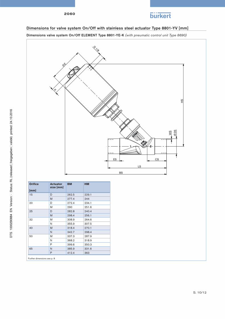
Dimensions for valve system On/Off with stainless steel actuator Type 8801-YV [mm]
Dimensions valve system On/Off ELEMENT Type 8801-YE-K (with pneumatic control unit Type 8690)
Orifi ce
[mm]
Actuator size [mm]
BM HM
15 D 262.5 229.1
M 277.4 244
20 D 272.4 234.1
M 290 251.6
25 D 282.8 240.4
M 298.4 256.1
32 M 308.9 264.6
N 355.9 307.5
40 M 318.4 270.1
N 342.7 298.4
50 M 337.3 287.9
N 368.2 318.9
P 399.6 350.3
65 N 385.9 331.6
P 412.4 363
Further dimensions see p. 8
LS
BS
ES
D
S
E
HS
K
WS
G 1/8
CS

S. 11/12
2060
Ordering chart for accessories
Accessories has to be ordered separately
Acce
sso
ry
for
actu
ato
r siz
e
Item no.
Stainless steel Silencer Set
(VA-Silencer incl. PTFE sealing ring)
universal 696 931
Max. stroke limitation D (Ø50), M (Ø70) 699 550
N (Ø90), P (Ø130) 699 994
Min.-/Max. stroke limitation D (Ø50), M (Ø70) 699 986
N (Ø90), P (Ø130) 699 998
Proximity switch (single) D (Ø50), M (Ø70) 699 989
N (Ø90), P (Ø130) 699 991
Proximity switch (double) D (Ø50), M (Ø70) 699 990
N (Ø90), P (Ø130) 699 992
Adaptionsset 8697* D (Ø50), M (Ø70) 699 551
N (Ø90), P (Ø130) 580 000
8697* universal depending
on version
For further accessories see accessories datasheet Type 2XXX for the full options programme.
Valve system On/Off ELEMENT Type 8801-YE – request for quotation
Please fill out and send to your nearest Bürkert facility* with your inquiry or order
Company Contact person
Customer no. Department
Address Tel./Fax
Postcode/town E-Mail
= mandatory fi elds to fi ll out Quantity Required delivery date
Operating data
Pipe line DN PN
Pipe material
Process medium
Type of media Liquid Steam Gas
Valve features
Seal material PTFE NBR Other
Nominal pressure PN
Orifi ce DN
Type of connection Threaded Welded Clamp
Standard connection ISO DIN Other
Control function NC 1) NO 1) Double-acting
Pilot pressure min. max.
Atex II 2GD Mechanical
Please specify item no. (if known): 1) NC: normally closed by spring action; NO: normally oppen by spring action
Note
You can fill out
the fields directly
in the PDF file
before printing
out the form.
Continued on next page

S. 12/12
2060
In case of special application conditions,
please consult for advice.
Subject to alteration.
© Christian Bürkert GmbH & Co. KG 1604/0_EU-en_00895312
Valve system On/Off ELEMENT Type 8801-YE – request for quotation, continued
Automation unit features
Click on the orange box "More info"… you will come to our website for the resp. product where you can download the data sheet.
Electrical Feedback
Type 8697
For actuator size 50 to 130
• LED-position indicator
• Micro- or proximity switches for end position feedback
• Gehäuse nach IP 65/67, 4X Rating
• Optional intrinsically safe version acc. to ATEX / IECEx
Position feedback switches Electrical connection
Micro-switch 24V DC Cable gland
Micro-switch 50 – 225 V DC/AC
Inductive switch 3-wire PNP M12 plug
Inductive switch 2-wire NAMUR (only with inductive switch
Inductive switch 2-wire 24V DC 3-wire PNP)
No. of Position feedback switches Approvals
2x ATEX cat. 3GD, IECEx
ATEX cat. 2DG, IECEx
without
Comment /sketch
Certifications
Attestation of compliance with the order EN-ISO 10204 2.1 (Item-No. 440 788)
Test report EN-ISO 10204 2.2 (Item-No. 803 722)
Certifi cation of Conformity for Raw Material EN-ISO 10204 3.1 (Included in delivery)
FDA compliance
Compliance EC-Regulation 1935/2004
To fi nd your nearest Bürkert facility, click on the orange box
www.burkert.com