technical specification for pneumatically operated … · 2012-10-11 · technical specification...
TRANSCRIPT
ANNEXURE- C TO ENQUIRY BAP/FGD/2012/OT-4
BONGAIGAON– 3X250 MW FLUE GAS DESULFURIZATION SYSTEM
TECHNICAL SPECIFICATION FOR
PNEUMATICALLY OPERATED
GLOBE VALVES HANDLING WATER
CUSTOMER : NATIONAL THERMAL POWER CORPORATION LIMITED
NTPC: BONG: FGD: WVALVES-GLOBE VALVE SPEC-025A: REV-01
Flue Gas Desulphurization Group Air Quality Control Systems BAP :: BHEL :: Ranipet
TECHNICAL SPECIFICATION FOR
PNEUMATIC GLOBE VALVES FOR PROCESS WATER APPLICATION
NTPC: BONG: FGD: WVALVES-GLOBE VALVE-SPEC-025A:REV-01
Page 2 of 20
TECHNICAL SPECIFICATION FOR PNEUMATIC GLOBE VALVES FOR PROCESS WATER APPLICATION
Prepared Checked Approved
ASHWIN R Engineer-FGD
MANOJ THAKUR Engineer - FGD
SASHI KUMAR Senior Engineer-FGD
Rev 01 dated 04 09 2012
TECHNICAL SPECIFICATION FOR
PNEUMATIC GLOBE VALVES FOR PROCESS WATER APPLICATION
NTPC: BONG: FGD: WVALVES-GLOBE VALVE-SPEC-025A:REV-01
Page 3 of 20
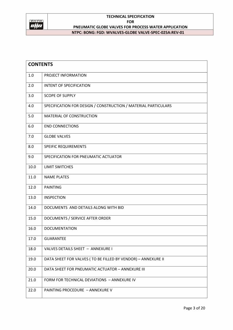
CONTENTS
1.0 PROJECT INFORMATION
2.0 INTENT OF SPECIFICATION
3.0 SCOPE OF SUPPLY
4.0 SPECIFICATION FOR DESIGN / CONSTRUCTION / MATERIAL PARTICULARS
5.0 MATERIAL OF CONSTRUCTION
6.0 END CONNECTIONS
7.0 GLOBE VALVES
8.0 SPEIFIC REQUIREMENTS
9.0 SPECIFICATION FOR PNEUMATIC ACTUATOR
10.0 LIMIT SWITCHES
11.0 NAME PLATES
12.0 PAINTING
13.0 INSPECTION
14.0 DOCUMENTS AND DETAILS ALONG WITH BID
15.0 DOCUMENTS / SERVICE AFTER ORDER
16.0 DOCUMENTATION
17.0 GUARANTEE
18.0 VALVES DETAILS SHEET – ANNEXURE I
19.0 DATA SHEET FOR VALVES ( TO BE FILLED BY VENDOR) – ANNEXURE II
20.0 DATA SHEET FOR PNEUMATIC ACTUATOR – ANNEXURE III
21.0 FORM FOR TECHNICAL DEVIATIONS – ANNEXURE IV
22.0 PAINTING PROCEDURE – ANNEXURE V
TECHNICAL SPECIFICATION FOR
PNEUMATIC GLOBE VALVES FOR PROCESS WATER APPLICATION
NTPC: BONG: FGD: WVALVES-GLOBE VALVE-SPEC-025A:REV-01
Page 4 of 20
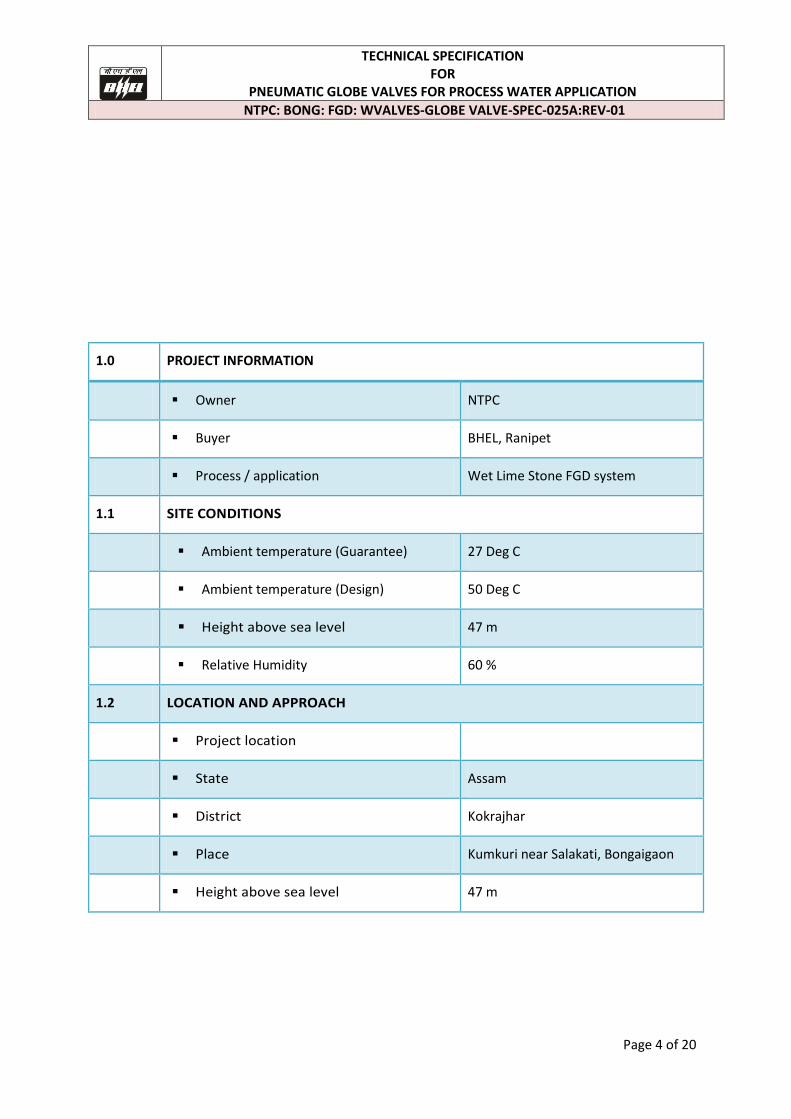
1.0 PROJECT INFORMATION
Owner NTPC
Buyer BHEL, Ranipet
Process / application Wet Lime Stone FGD system
1.1 SITE CONDITIONS
Ambient temperature (Guarantee) 27 Deg C
Ambient temperature (Design) 50 Deg C
Height above sea level 47 m
Relative Humidity 60 %
1.2 LOCATION AND APPROACH
Project location
State Assam
District Kokrajhar
Place Kumkuri near Salakati, Bongaigaon
Height above sea level 47 m
TECHNICAL SPECIFICATION FOR
PNEUMATIC GLOBE VALVES FOR PROCESS WATER APPLICATION
NTPC: BONG: FGD: WVALVES-GLOBE VALVE-SPEC-025A:REV-01
Page 5 of 20
2.0 INTENT OF SPECIFICATION
This specification together with the attendant Technical Data Sheet and other specifications/attachments to inquiry / order defines the minimum requirements for pneumatically globe valves along with their accessories /auxiliaries handling process water for use in the process of Flue gas Desulphurization (FGD) system.
Bidder shall make all possible efforts to comply strictly with the requirements of this specification and other specifications/attachments to inquiry/order.
In case, deviations are considered essential by the Bidder (after exhausting all possible efforts), these shall be separately listed in the Bidder's proposal under separate section, titled as "List of Deviations/Exceptions to the Enquiry Document (Annexure-IV)". Deviation shall be listed separately for each document with cross reference to Page No./Section/Clause No./Para etc. of the respective document supported with proper reasons for the deviation for purchaser's consideration. Any deviation, not listed under the above section, even if reflected in any other portion of the proposal, shall not be considered applicable. No deviation or exception shall be permitted without the written approval of the purchaser.
The design, material, construction, manufacture, inspection, testing and performance of valves shall comply with all currently applicable statutes, regulations and safety codes in the locality where the valves will be installed. The valves shall conform to the latest editions of applicable codes and standards as mentioned elsewhere. Nothing in this specification shall be construed to relieve the Bidder of his responsibility. Compliance to this specification shall not relieve the Bidder of the responsibility of furnishing equipment and accessories/auxiliaries of proper design, materials and workmanship to meet the specified start up and operating conditions.
In case the Bidder considers requirement of additional instrumentation, controls, safety devices and any other accessories/auxiliaries essential for safe and satisfactory operation of the equipment, he shall recommend the same along with reasons in a separate section along with his proposal and include the same in his scope of supply. The Bidder shall offer only proven design in successful operation.
Valves in general shall conform to the requirements of the following standards:
IS-778 Gun-metal gate, globe and check valves for general purpose. BS-5154 Copper alloy globe/globe stop and check and gate valves for general purpose. BS-5152 Specification for cast iron globe valves. ANSI B 16.34 Standard for valves. ANSI-B-16.10 Valves face to face and other relevant dimension. API-598 Valves inspection test.
TECHNICAL SPECIFICATION FOR
PNEUMATIC GLOBE VALVES FOR PROCESS WATER APPLICATION
NTPC: BONG: FGD: WVALVES-GLOBE VALVE-SPEC-025A:REV-01
Page 6 of 20
3.0 SCOPE OF SUPPLY
a) Valve as per specification b) Pneumatic actuator as per the specification No. c) Limit switch – 2 Nos. for each valves as per the spec. d) Air filter Regulator -1 No. per valve as per the spec. e) Solenoid valve – 1 No. for each valve as per the spec.
4.0 GENERAL SPECIFICATION FOR DESIGN/CONSTRUCTION/MATERIAL PARTICULARS OF GLOBE/ GLOBE STOP VALVE
a) All valves shall be suitable for the service conditions i.e flow, temperature and pressure, at which they are required to operate.
b) The valves as well as all accessories shall be designed for easy disassembly and maintenance.
c) Valves to be installed outside shall be required to have the stem properly protected against atmospheric corrosion.
d) For all globe and check valves, the direction of flow shall be clearly stamped on the body of the valve.
e) All gate and globe valves shall have bonnet-back seating arrangement f) All rising stem valves shall be provided with back seat to permit repacking (of
glands) with valves in operation. All valves shall preferably be of outside screw and yoke type.
g) All valves shall be closed by rotating the hand wheel in the clockwise direction when looking at the face of the hand wheel. In case where the hand wheel is not directly attached to the valve spindle suitable gearing shall be introduced.
h) All valves shall have indicators or direction clearly marked on the hand-wheel so that the valves opening/ closing can be readily determined.
i) The actuator-operated valves shall be designed on the basis of the following : (1) The internal parts shall be suitable to support the pressure caused by the
actuators; (2) The valve-actuator unit shall be suitably stiff so as not to cause vibrations,
misalignments, etc. (3) All actuator operated valves shall be provided with hand operated gearing
mechanism also.
(4) All actuators operated valves shall open/ close fully within time required by the process but not later than 60 seconds after actuators starts.
j) Globe valves shall be used for isolation/regulation purposes as provided in Annexure I. They shall be provided with hand wheel, position indicator, draining arrangement (wherever required) and arrow indicating flow direction. All globe valves shall be capable of being closed against the design pressure. Where globe valve has been specified for regulation purpose, the disc shall be tapered plug type and suitable for controlling throughout its lift.
TECHNICAL SPECIFICATION FOR
PNEUMATIC GLOBE VALVES FOR PROCESS WATER APPLICATION
NTPC: BONG: FGD: WVALVES-GLOBE VALVE-SPEC-025A:REV-01
Page 7 of 20
k) All globe valves shall be rising stem type and shall have limit switches for full OPEN and full CLOSED indication wherever required. In such cases the limit switches shall form an integral part of the valve. Stop-gap arrangement in this respect is not acceptable.
l) All valves except those with rising stems shall be provided with continuous mechanical position indicators; rising stem valves shall have only visual indication through plastic/metallic stem cover for sizes above 50 mm nominal bore. Valves of 65 mm Nb & above with rising stem shall be provided with position indicator/ visual indication either through plastic stem covers or through metallic stem covers.
m) All globe valves shall be provided with bonnet-back seating arrangement to enable on line changing of gland packing.
n) Hand wheels for all the valves shall close the valve in clockwise direction when viewing from the top. All hand wheels shall be clearly marked indicating the direction of opening/closing. Manual gear operators shall be provided to open/close the valve against the maximum differential pressure across the valve such that the effort required to operate the valve does not exceed 25 kgf.
o) All globe valves shall be designed for reconditioning seating surfaces and replacement of stem and disc without removing the valve body from the line
p) All valves shall be provided with embossed name plate giving details such as tag number, type, size etc.
q) For globe valves wherever thickness of body/bonnet is not mentioned in the valves standards, thickness mentioned in IS- 1538 for fitting shall be applicable.
r) All valves shall be provided with proper name plates indicating complete information about the valves
s) Where floors and extension spindle arrangements is required for valves, the height of floor stand shall be about one meter from the floor/platform. The floor stand shall be sturdy construction with column, nut plate and hand wheel made of the cast iron conforming to material ASTM-A-126 Grade B. Suitable thrust bearing shall be provided/between the hand wheel and floor stand. The connection of the extension spindle to the valve stem shall be through a flexible coupling and shall be designed to permit valve thermal movements. Necessary nuts, bolts etc. for mounting the floor stand on platform shall be provided.
5.0 MATERIAL OF CONSTRUCTION (GLOBE VALVE)
Material of Globe valves for process water application shall be as per enclosed Annexure – I or its equivalent. Vendor shall provide the counter flange along with necessary nuts, bolts, gaskets etc.
Material for counter flanges shall be the same as for the piping.
6.0 END CONNECTIONS
End connection for Globe valves shall be as per enclosed Annexure-I.
TECHNICAL SPECIFICATION FOR
PNEUMATIC GLOBE VALVES FOR PROCESS WATER APPLICATION
NTPC: BONG: FGD: WVALVES-GLOBE VALVE-SPEC-025A:REV-01
Page 8 of 20
7.0 GLOBE VALVES
The globe valves shall have the following characteristics:
a) Straight conveyed flow, right angle preferably, the valves shall be of the vertical stem type.
b) Globe valves shall preferably have radiusd or spherical seating and discs shall be free to revolve on the spindle.
c) The pressure shall preferably be under the disc of the valve. However, globe valves, with pressure over the disc shall also be accepted provided
(i) no possibility exists that flow from above the disc can remove either the disc from stem or component from disc
(ii) manual globe valves can easily be operated by hand. If the fluid load on the top of the disc is higher than 40-60 KN, bypass valve shall be provided which permits the downstream system to be pressurised before the globe valve is opened.
d) Globe valves with NB smaller than or equal to 2" shall be of the integral type. Valves of this type shall be so as to permit the easiest disassembly of the internals (stem and disc).
e) For the regulating valves, valves with regulating plug & parabolic outline disc type is preferred.
8.0 SPECIFIC REQUIREMENTS FOR GLOBE VALVES
a) All valves shall be full port as per ANSI B 16.34. b) Locking arrangement, wherever specified shall be of non-detachable type. c) Valves shall be tested in accordance to ANSI B 16.34. d) All globe valves shall be with outside screw and yoke with rising stem. e) Gate valves below 100 NB shall be solid wedge/flexible wedge type, valves of size 100
NB and above shall be of flexible wedge type. However, for sizes 100 mm and above for Temperatures above 300oC, parallel slide valves are also acceptable.
f) Stem for all valves shall be heat treated and hardened - minimum, hardness 200 HB and surface finish of 16 RMS or better in area of stem packing.
g) Gland packing for gate and globe valves shall be alloy steel/SS wire reinforced graphite with stem corrosion inhibitor.
h) All bolts and nuts shall be ASTM A-193 Gr. B 7 and ASTM A-194 Gr. 2H respectively. i) Hand wheels for valves shall be of malleable iron / Carbon steel. j) Minimum differential hardness between seat and other disc material shall be 50 HB in
case of 13% chrome hardened with heat treatment of steel. k) Valve closure test shall be as per ANSI B16.34 and MSS-SP-61. Acceptable maximum
seat leakage shall be 2 ml of water per hour per 25 mm of nominal pipe size. l) Safety and Relief valves shall be supplied complete with discharge elbow and drip pan
along with drain.
TECHNICAL SPECIFICATION FOR
PNEUMATIC GLOBE VALVES FOR PROCESS WATER APPLICATION
NTPC: BONG: FGD: WVALVES-GLOBE VALVE-SPEC-025A:REV-01
Page 9 of 20
m) For valves of size 65 NB and above in vacuum service, water gland sealing arrangement shall be provided. For valves of size 50 NB and below, deep gland packing shall be provided.
9.0 SPECIFICATION FOR PNEUMATIC ACTUATOR
a) Quantity : 01 No. for each valve
b) Type : Rotary actuator, Pneumatic (spring return)
c) Action : Air to open
d) Failure position (air failure) : Close
e) Close/open at air Pressure : 4 to 6 Kg/sq.cm
e) Air Connection : ¼” NPT(F)
f) Local Position Indicator : To be provided.
g) Hand wheel for manual opn : Required (for valves greater than 8 inch)
h) Actuator travel time : Vendor to specify
i) Actuator Protection Class : IP-65 (Min)
j) Actuator Thrust : Vendor to specify
k) Spring range (kg/cm2) : Vendor to specify
l) Speed adjustment for actuator : To be provided to facilitate speed adjustments
Operation both during opening &closing by means of
flow control valve
m) Solenoid valve type : 3/2 way, 24V DC power supply, ex. proof,
1/4" NPT pneumatic connection, 1/2" NPT
Electrical connection. Solenoid Valve Energised
for valve to open & Solenoid valve De-
energised for valve to close.
n) Air filter regulator : Size of filter shall be 5 Micron, Filter material
shall be sintered bronze/equivalent, Body shall
be aluminium, 1/4" NPT Pneumatic connection
shall be envisaged.
10. LIMIT SWITCHES
a) Quantity /valve : One for Open & one for Close position b) No. of Contacts : Two normally open & two normally closed potential free contacts in each limit switch corresponding to open & close positions of the valve. c) Contact Rating : 24 V DC d) Protection : Weather proof IP 55. e) Limit Switch Box : Limit Switch terminals shall be brought out to a Terminal Box
TECHNICAL SPECIFICATION FOR
PNEUMATIC GLOBE VALVES FOR PROCESS WATER APPLICATION
NTPC: BONG: FGD: WVALVES-GLOBE VALVE-SPEC-025A:REV-01
Page 10 of 20
11.0 NAME PLATES
Each equipment / instrument shall be provided with rating plate or nameplate or label designating the tag no., service of the item etc. 12.0 PAINTING
The detailed painting procedure is enclosed in Annexure-V . Bidder to note that If during transport, unloading/unpacking or erection at site any part of the painted surface gets damaged, the same shall be made good by the contractor by repainting with compatible painting primer and enamel to the satisfaction of the project manager.
13.0 INSPECTION
The valves shall be inspected at Vendor’s works by BHEL Engineer as per the
procedure submitted by the Vendor.
14.0 DOCUMENTS / DETAILS ALONG WITH BID
The following information / documents shall be submitted along with the offer a. Duly filled up data sheet for each valve type as per Annexure-II and III in the
enclosed format. b. Detailed assembly drawing with overall dimensions. c. Valve cross sectional drawings with Bill of Material including the material
specifications. d. Valve Regulation Characteristic Curve. e. Cv calculation. f. List of applicable standards for shop test. g. Reference list for the offered model. h. Typical Quality plan for supply of the above equipments. i. Valves Catalogues. j. List of commissioning spares. k. Recommended spares list for 3 year O&M along with item wise price. l. Any deviation shall be specifically mentioned in the enclosed deviation format
Annexure-IV. In case of any deviation, the Bidder shall indicate the deviation, clause by clause in the deviation format attached in Annexure-IV. If there is no deviation “NIL” statement shall be furnished. In the absence of Annexure-IV, it will be construed that the bid confirms strictly to the specification. Acceptance or rejection of the offer with or without deviations (either fully or partially) is sole discretion of the purchaser without seeking further clarification from the bidder. NOTE: Bidders to note that failing to submit the above documents, the bid shall be considered as incomplete and liable for rejection.
TECHNICAL SPECIFICATION FOR
PNEUMATIC GLOBE VALVES FOR PROCESS WATER APPLICATION
NTPC: BONG: FGD: WVALVES-GLOBE VALVE-SPEC-025A:REV-01
Page 11 of 20
15.0 DOCUMENTS / SERVICE AFTER ORDER
16.1. The following documents are to be submitted for BHEL's approval. Duly filled up data sheet in the enclosed format. Detailed assembly drawing with overall dimensions. Valve cross sectional drawings with Bill of Material including the
material specifications. Cv Calculation Quality plan
16.2. The following are to be submitted to BHEL's review and acceptance.
Material test certificate
Hydraulic & Leak test certificates
Performance guarantee certificate
Erection manual
O&M manuals
16.0 DOCUMENTATION
a. The documentation during bid and post order stage shall meet the following requirements.
b. All documents and drawings shall be submitted in English. c. Hard copies of all documents and drawings during bid stage to be submitted
in duplicate. d. Hard copies of all documents for approval to be submitted in triplicate. e. Hard copies of all final documents, drawings, manual etc., shall be submitted
in bound folder in duplicate. f. Soft copies of all final documents in MS office in the form of CD-1 set. g. Soft copies of all final drawings in AutoCAD, latest version in form of CD-1 set
17.0 GUARANTEE The Vendor shall provide guarantee for a period of 12 months from the date of commissioning or 24 months from the date of supply whichever is earlier.
TECHNICAL SPECIFICATION FOR
PNEUMATIC GLOBE VALVES FOR PROCESS WATER APPLICATION
NTPC: BONG: FGD: WVALVES-GLOBE VALVE-SPEC-025A:REV-01
Page 12 of 20
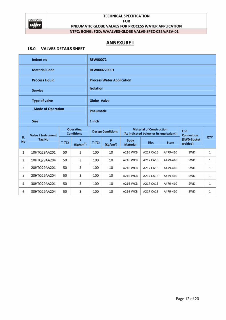
ANNEXURE I 18.0 VALVES DETAILS SHEET
Indent no RFW00072
Material Code RFW000720001
Process Liquid Process Water Application
Service Isolation
Type of valve Globe Valve
Mode of Operation
Pneumatic
Size 1 inch
Sl.No
Valve / Instrument Tag No
Operating Conditions
Design Conditions Material of Construction
(As indicated below or its equivalent) End Connection (SWD-Socket welded)
QTY
T (°C) P
(Kg/cm2)
T (°C) P
(Kg/cm²) Body
Material Disc Stem
1 10HTQ29AA201 50 3 100 10 A216 WCB A217 CA15 A479-410 SWD 1
2 10HTQ29AA204 50 3 100 10 A216 WCB A217 CA15 A479-410 SWD 1
3 20HTQ29AA201 50 3 100 10 A216 WCB A217 CA15 A479-410 SWD 1
4 20HTQ29AA204 50 3 100 10 A216 WCB A217 CA15 A479-410 SWD 1
5 30HTQ29AA201 50 3 100 10 A216 WCB A217 CA15 A479-410 SWD 1
6 30HTQ29AA204 50 3 100 10 A216 WCB A217 CA15 A479-410 SWD 1
TECHNICAL SPECIFICATION FOR
PNEUMATIC GLOBE VALVES FOR PROCESS WATER APPLICATION
NTPC: BONG: FGD: WVALVES-GLOBE VALVE-SPEC-025A:REV-01
Page 13 of 20
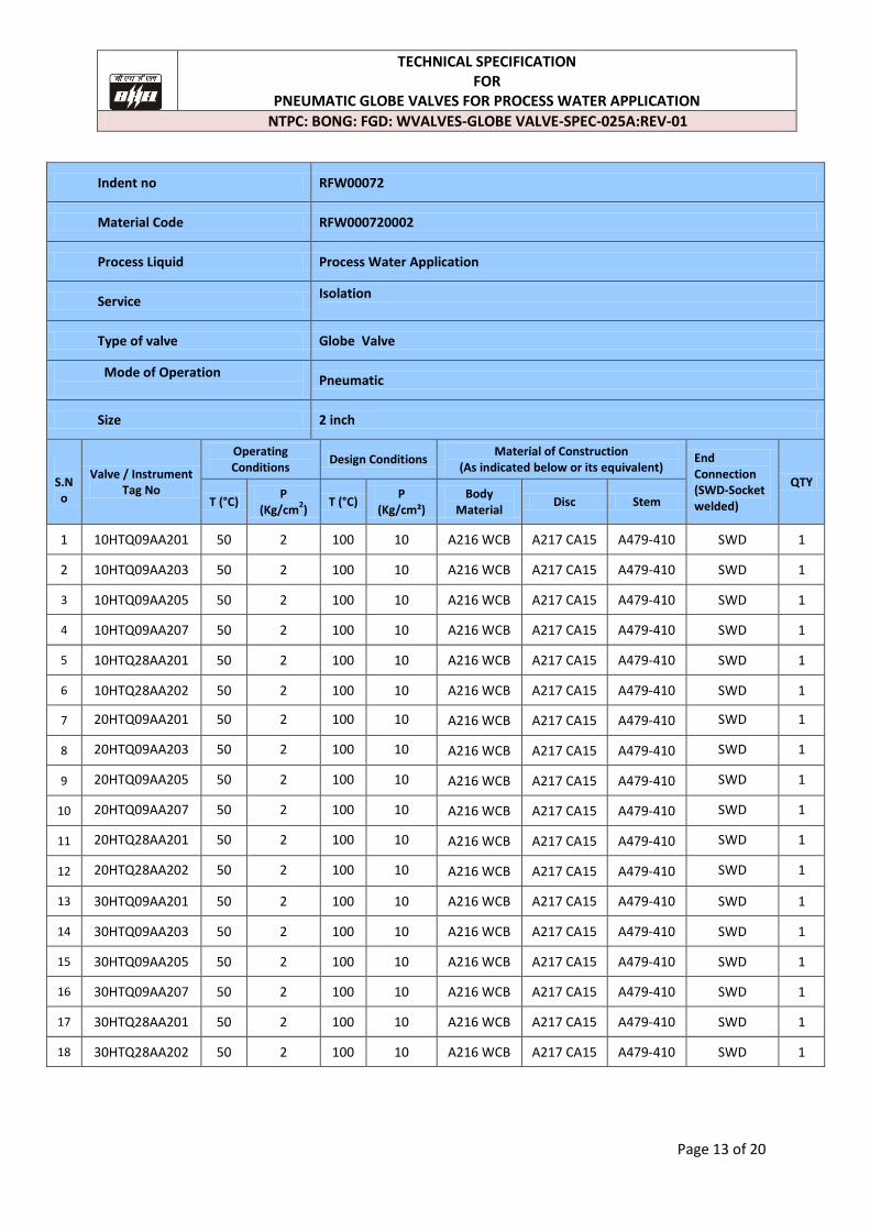
Indent no RFW00072
Material Code RFW000720002
Process Liquid Process Water Application
Service Isolation
Type of valve Globe Valve
Mode of Operation
Pneumatic
Size 2 inch
S.No
Valve / Instrument Tag No
Operating Conditions
Design Conditions Material of Construction
(As indicated below or its equivalent) End Connection (SWD-Socket welded)
QTY
T (°C) P
(Kg/cm2)
T (°C) P
(Kg/cm²) Body
Material Disc Stem
1 10HTQ09AA201 50 2 100 10 A216 WCB A217 CA15 A479-410 SWD 1
2 10HTQ09AA203 50 2 100 10 A216 WCB A217 CA15 A479-410 SWD 1
3 10HTQ09AA205 50 2 100 10 A216 WCB A217 CA15 A479-410 SWD 1
4 10HTQ09AA207 50 2 100 10 A216 WCB A217 CA15 A479-410 SWD 1
5 10HTQ28AA201 50 2 100 10 A216 WCB A217 CA15 A479-410 SWD 1
6 10HTQ28AA202 50 2 100 10 A216 WCB A217 CA15 A479-410 SWD 1
7 20HTQ09AA201 50 2 100 10 A216 WCB A217 CA15 A479-410 SWD 1
8 20HTQ09AA203 50 2 100 10 A216 WCB A217 CA15 A479-410 SWD 1
9 20HTQ09AA205 50 2 100 10 A216 WCB A217 CA15 A479-410 SWD 1
10 20HTQ09AA207 50 2 100 10 A216 WCB A217 CA15 A479-410 SWD 1
11 20HTQ28AA201 50 2 100 10 A216 WCB A217 CA15 A479-410 SWD 1
12 20HTQ28AA202 50 2 100 10 A216 WCB A217 CA15 A479-410 SWD 1
13 30HTQ09AA201 50 2 100 10 A216 WCB A217 CA15 A479-410 SWD 1
14 30HTQ09AA203 50 2 100 10 A216 WCB A217 CA15 A479-410 SWD 1
15 30HTQ09AA205 50 2 100 10 A216 WCB A217 CA15 A479-410 SWD 1
16 30HTQ09AA207 50 2 100 10 A216 WCB A217 CA15 A479-410 SWD 1
17 30HTQ28AA201 50 2 100 10 A216 WCB A217 CA15 A479-410 SWD 1
18 30HTQ28AA202 50 2 100 10 A216 WCB A217 CA15 A479-410 SWD 1
TECHNICAL SPECIFICATION FOR
PNEUMATIC GLOBE VALVES FOR PROCESS WATER APPLICATION
NTPC: BONG: FGD: WVALVES-GLOBE VALVE-SPEC-025A:REV-01
Page 14 of 20
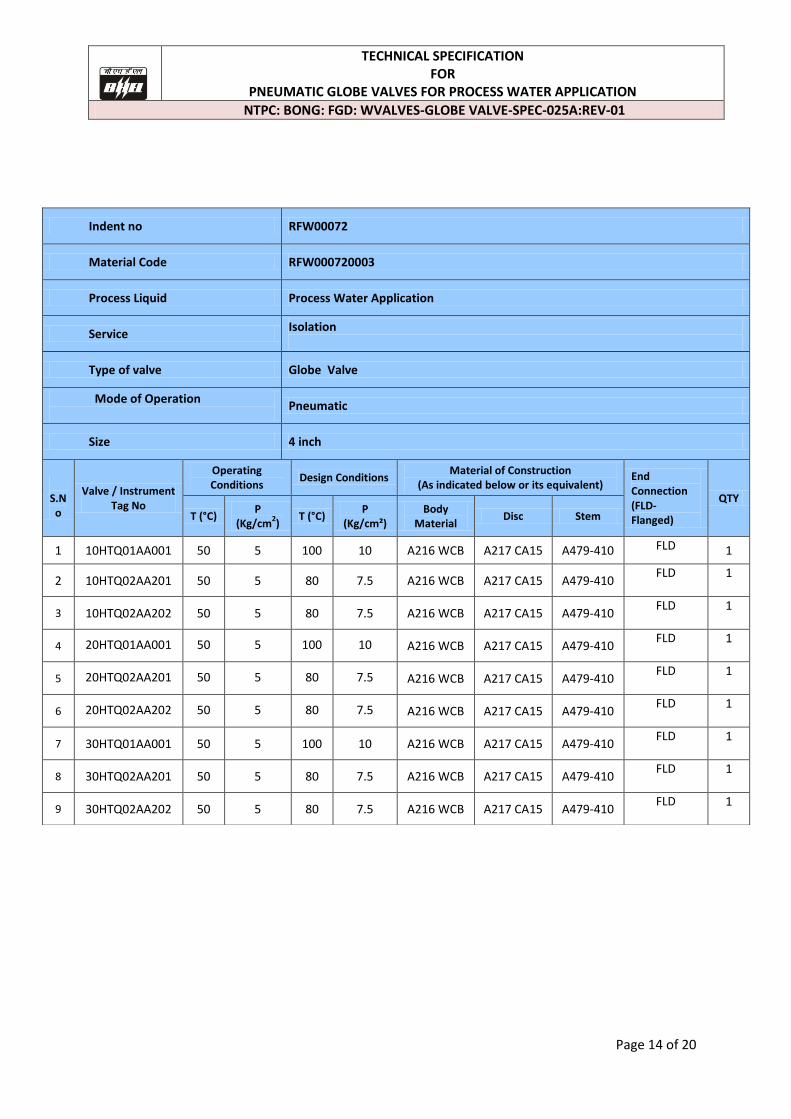
Indent no RFW00072
Material Code RFW000720003
Process Liquid Process Water Application
Service Isolation
Type of valve Globe Valve
Mode of Operation
Pneumatic
Size 4 inch
S.No
Valve / Instrument Tag No
Operating Conditions
Design Conditions Material of Construction
(As indicated below or its equivalent) End Connection (FLD- Flanged)
QTY
T (°C) P
(Kg/cm2)
T (°C) P
(Kg/cm²) Body
Material Disc Stem
1 10HTQ01AA001 50 5 100 10 A216 WCB A217 CA15 A479-410 FLD 1
2 10HTQ02AA201 50 5 80 7.5 A216 WCB A217 CA15 A479-410 FLD 1
3 10HTQ02AA202 50 5 80 7.5 A216 WCB A217 CA15 A479-410 FLD 1
4 20HTQ01AA001 50 5 100 10 A216 WCB A217 CA15 A479-410 FLD 1
5 20HTQ02AA201 50 5 80 7.5 A216 WCB A217 CA15 A479-410 FLD 1
6 20HTQ02AA202 50 5 80 7.5 A216 WCB A217 CA15 A479-410 FLD 1
7 30HTQ01AA001 50 5 100 10 A216 WCB A217 CA15 A479-410 FLD 1
8 30HTQ02AA201 50 5 80 7.5 A216 WCB A217 CA15 A479-410 FLD 1
9 30HTQ02AA202 50 5 80 7.5 A216 WCB A217 CA15 A479-410 FLD 1
TECHNICAL SPECIFICATION FOR
PNEUMATIC GLOBE VALVES FOR PROCESS WATER APPLICATION
NTPC: BONG: FGD: WVALVES-GLOBE VALVE-SPEC-025A:REV-01
Page 15 of 20
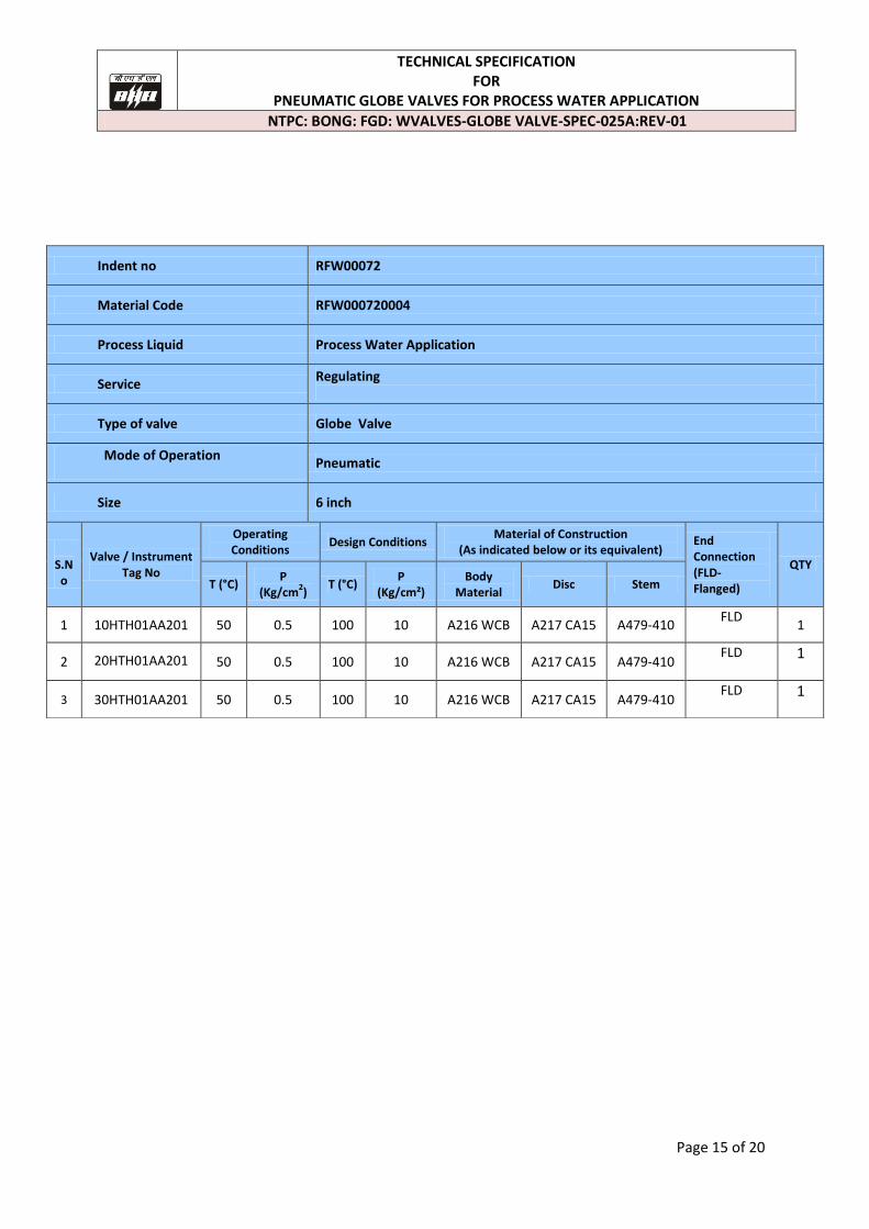
Indent no RFW00072
Material Code RFW000720004
Process Liquid Process Water Application
Service Regulating
Type of valve Globe Valve
Mode of Operation
Pneumatic
Size 6 inch
S.No
Valve / Instrument Tag No
Operating Conditions
Design Conditions Material of Construction
(As indicated below or its equivalent) End Connection (FLD- Flanged)
QTY
T (°C) P
(Kg/cm2)
T (°C) P
(Kg/cm²) Body
Material Disc Stem
1 10HTH01AA201 50 0.5 100 10 A216 WCB A217 CA15 A479-410 FLD
1
2 20HTH01AA201 50 0.5 100 10 A216 WCB A217 CA15 A479-410 FLD 1
3 30HTH01AA201 50 0.5 100 10 A216 WCB A217 CA15 A479-410 FLD 1
TECHNICAL SPECIFICATION FOR
PNEUMATIC GLOBE VALVES FOR PROCESS WATER APPLICATION
NTPC: BONG: FGD: WVALVES-GLOBE VALVE-SPEC-025A:REV-01
Page 16 of 20
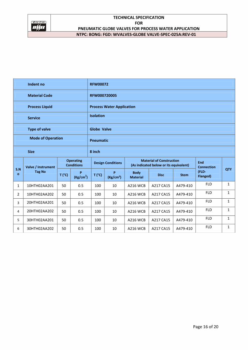
Indent no RFW00072
Material Code RFW000720005
Process Liquid Process Water Application
Service Isolation
Type of valve Globe Valve
Mode of Operation
Pneumatic
Size 8 inch
S.No
Valve / Instrument Tag No
Operating Conditions
Design Conditions Material of Construction
(As indicated below or its equivalent) End Connection (FLD- Flanged)
QTY
T (°C) P
(Kg/cm2)
T (°C) P
(Kg/cm²) Body
Material Disc Stem
1 10HTH02AA201 50 0.5 100 10 A216 WCB A217 CA15 A479-410 FLD 1
2 10HTH02AA202 50 0.5 100 10 A216 WCB A217 CA15 A479-410 FLD 1
3 20HTH02AA201 50 0.5 100 10 A216 WCB A217 CA15 A479-410 FLD 1
4 20HTH02AA202 50 0.5 100 10 A216 WCB A217 CA15 A479-410 FLD 1
5 30HTH02AA201 50 0.5 100 10 A216 WCB A217 CA15 A479-410 FLD 1
6 30HTH02AA202 50 0.5 100 10 A216 WCB A217 CA15 A479-410 FLD 1
TECHNICAL SPECIFICATION FOR
PNEUMATIC GLOBE VALVES FOR PROCESS WATER APPLICATION
NTPC: BONG: FGD: WVALVES-GLOBE VALVE-SPEC-025: REV-00
Page 17 of 20
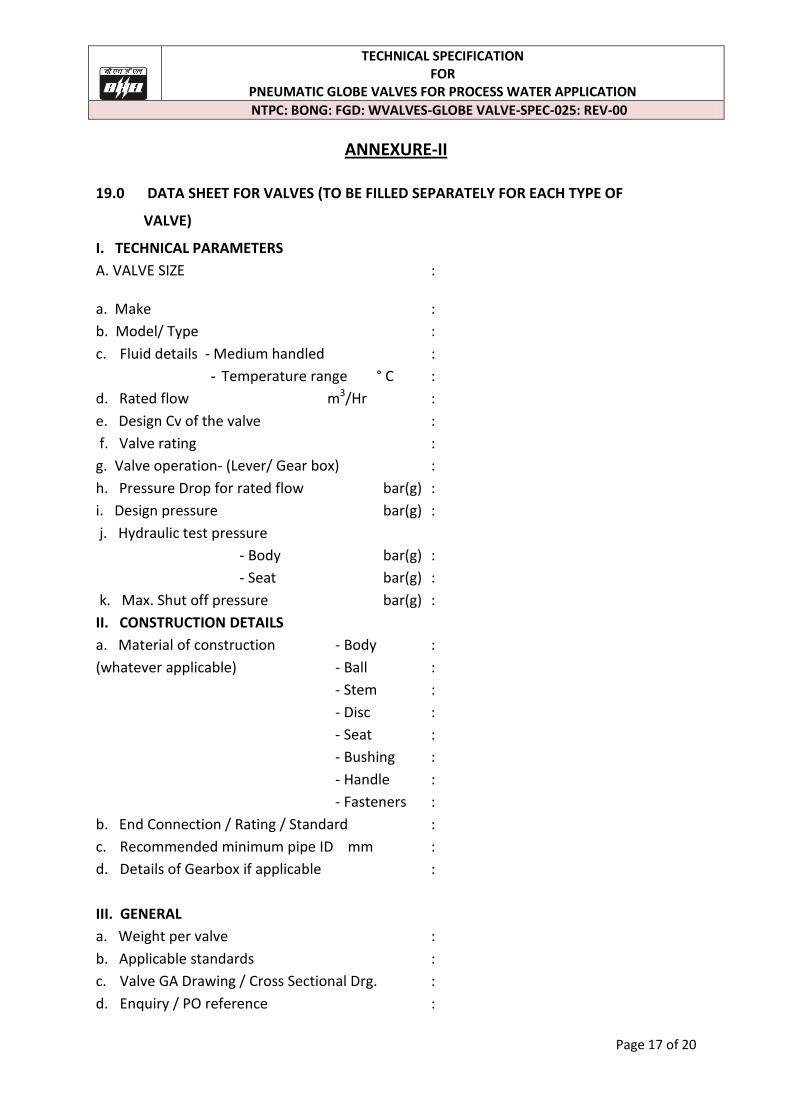
ANNEXURE-II
19.0 DATA SHEET FOR VALVES (TO BE FILLED SEPARATELY FOR EACH TYPE OF
VALVE)
I. TECHNICAL PARAMETERS
A. VALVE SIZE :
a. Make :
b. Model/ Type :
c. Fluid details - Medium handled :
- Temperature range ° C :
d. Rated flow m3/Hr :
e. Design Cv of the valve :
f. Valve rating :
g. Valve operation- (Lever/ Gear box) :
h. Pressure Drop for rated flow bar(g) :
i. Design pressure bar(g) :
j. Hydraulic test pressure
- Body bar(g) :
- Seat bar(g) :
k. Max. Shut off pressure bar(g) :
II. CONSTRUCTION DETAILS
a. Material of construction - Body :
(whatever applicable) - Ball :
- Stem :
- Disc :
- Seat :
- Bushing :
- Handle :
- Fasteners :
b. End Connection / Rating / Standard :
c. Recommended minimum pipe ID mm :
d. Details of Gearbox if applicable :
III. GENERAL
a. Weight per valve :
b. Applicable standards :
c. Valve GA Drawing / Cross Sectional Drg. :
d. Enquiry / PO reference :
TECHNICAL SPECIFICATION FOR
PNEUMATIC GLOBE VALVES FOR PROCESS WATER APPLICATION
NTPC: BONG: FGD: WVALVES-GLOBE VALVE-SPEC-025: REV-00
Page 18 of 20
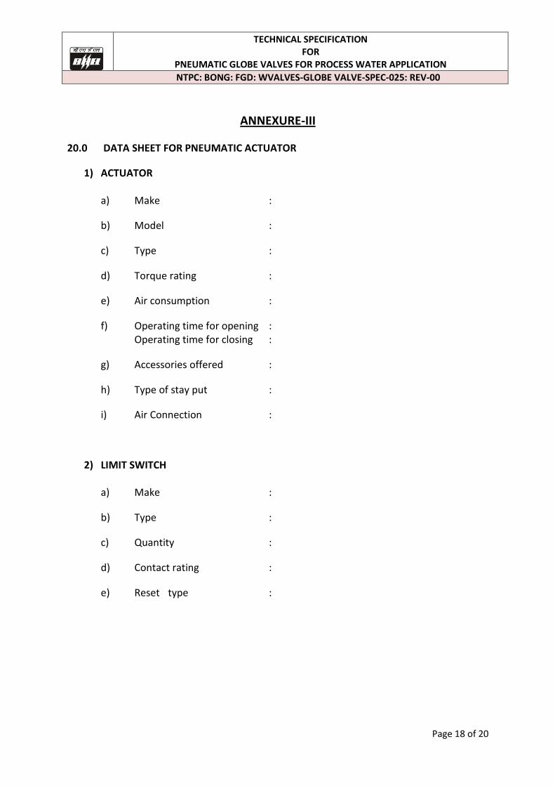
ANNEXURE-III
20.0 DATA SHEET FOR PNEUMATIC ACTUATOR
1) ACTUATOR a) Make :
b) Model :
c) Type :
d) Torque rating :
e) Air consumption :
f) Operating time for opening : Operating time for closing :
g) Accessories offered :
h) Type of stay put :
i) Air Connection :
2) LIMIT SWITCH a) Make :
b) Type :
c) Quantity :
d) Contact rating :
e) Reset type :
TECHNICAL SPECIFICATION FOR
PNEUMATIC GLOBE VALVES FOR PROCESS WATER APPLICATION
NTPC: BONG: FGD: WVALVES-GLOBE VALVE-SPEC-025: REV-00
Page 19 of 20
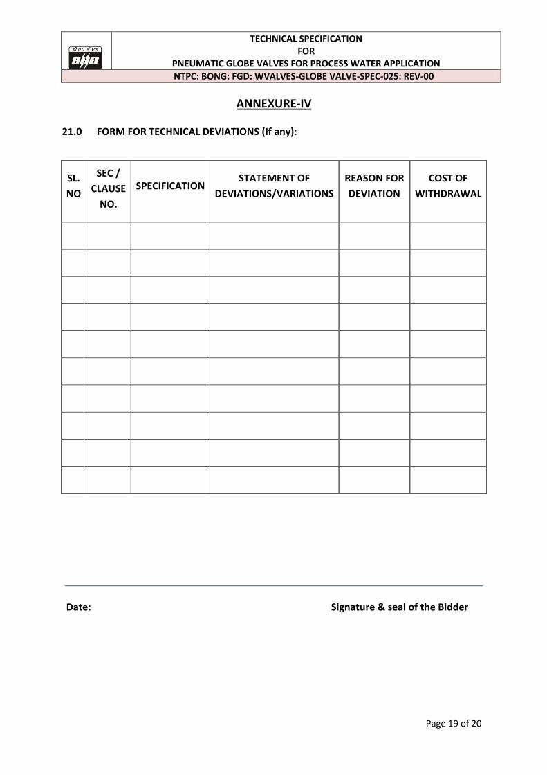
ANNEXURE-IV 21.0 FORM FOR TECHNICAL DEVIATIONS (If any):
SL.
NO
SEC /
CLAUSE
NO.
SPECIFICATION STATEMENT OF
DEVIATIONS/VARIATIONS
REASON FOR
DEVIATION
COST OF
WITHDRAWAL
Date: Signature & seal of the Bidder
TECHNICAL SPECIFICATION FOR
PNEUMATIC GLOBE VALVES FOR PROCESS WATER APPLICATION
NTPC: BONG: FGD: WVALVES-GLOBE VALVE-SPEC-025: REV-00
Page 20 of 20
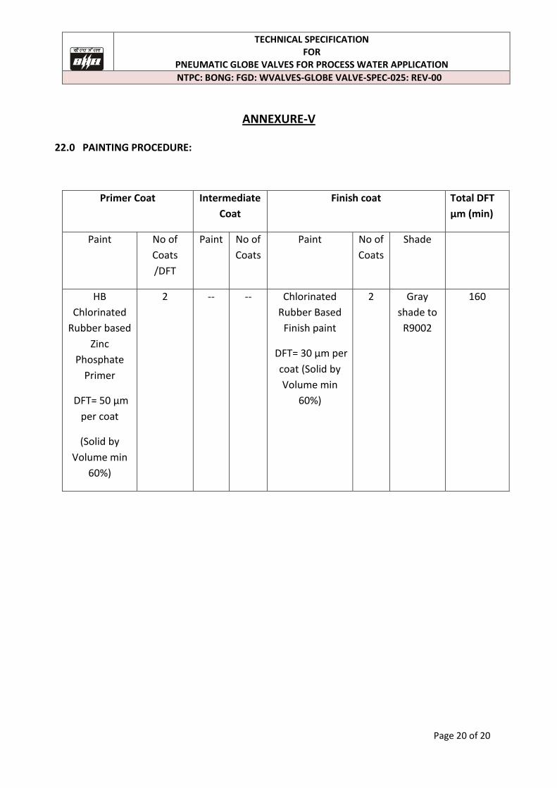
ANNEXURE-V
22.0 PAINTING PROCEDURE:
Primer Coat Intermediate
Coat
Finish coat Total DFT
µm (min)
Paint No of
Coats
/DFT
Paint No of
Coats
Paint No of
Coats
Shade
HB
Chlorinated
Rubber based
Zinc
Phosphate
Primer
DFT= 50 µm
per coat
(Solid by
Volume min
60%)
2 -- -- Chlorinated
Rubber Based
Finish paint
DFT= 30 µm per
coat (Solid by
Volume min
60%)
2 Gray
shade to
R9002
160