pmv d20 installation pmv d22 operation digital positioner ... · pmv d20 positioner accessories:...
TRANSCRIPT
InstallationOperation
Maintenance
PMV D20PMV D22Digital Positioner

2
Contents
1. General information ......................... 3 1.1 Using .............................................. 3 1.2 Terms concerning safety ................. 3 1.3 Protective clothing .......................... 4 1.4 Qualified personnel......................... 4 1.5 Installation ...................................... 4 1.6 Spare parts ..................................... 4 1.7 Service/repair ................................. 4 1.8 Storage ........................................... 5 1.9 Valve and actuator variations ......... 5
2. Unpacking ......................................... 5
3. Certificates ........................................ 5
4. PMV D20 Overview ........................... 6
5. Specifications ................................... 7 5.1 Technical data ................................. 7 5.2 Limit switches ................................. 8 5.3 Type sign ........................................ 9 5.4 D20 Model Code........................... 10 5.5 Control Drawing ............................ 12 6. Principle of operation ..................... 13
7. Mounting and installation .............. 14 7.1 General ......................................... 14 7.2 Dimensional drawing .................... 15 7.3 Mounting ....................................... 16
8. Tubing positioner to actuator ........ 21
9. Wiring and grounding guidelines 22 9.1 Grounding screw .......................... 22 9.2 Electromagnetic compability ......... 23 9.3 Compliance voltage ...................... 24
10. Operation D20 ............................... 25 10.1 Operation .................................... 25 10.2 Start up ....................................... 25 10.3 Calibration .................................. 25 10.4 Set of Direct or Reverse action... 26 10.5 Show gain setting ....................... 26 10.6 Change gain setting.................... 27
11. Operation D22 ............................... 28 11.1 Menus and pushbuttons ............ 28 11.2 Other functions .......................... 28 11.3 Menu indicator ........................... 29 11.4 Menus ........................................ 29 11.5 Changing parameter values ....... 29 11.6 Menu system ............................. 30 11.7 First start .................................... 31
12. Limit switches & 4 - 20 mA transmitter (Optional) ................... 44 12.1 General ....................................... 44 12.2 Model selection........................... 44 12.3 Principle of operation .................. 44 12.4 Installation .................................. 44 12.5 Calibration of 4 - 20 mA input signal and/or 4 - 20 mA feedback transmitter ................... 45
13. Trouble shooting .......................... 46 13.1 PMV D20 normal operation ........ 46 13.2 PMV D20 error codes ................. 46 13.3 PMV D20 symptoms and solutions 47
14. Maintenance/service .................... 48 14.1 Disassembling PMV D20 ............ 48 14.1 Disassembling PMV D22 ............ 49
15. Spare parts .................................... 50

3
1.1 UsingThe following instructions are designed to assist in unpacking, installing and performing maintenance as required on FLOWSERVE products. Product users and maintenance personnel should thoroughly review this bulletin prior to installing, operating or performing any maintenance.
1. General information
1.2 Terms concerning safetyThe safety terms DANGER, WAR-NING, CAUTION and NOTE are used in these instructions to high-light particular dangers and/or to provide additional information on aspects that may not be readily apparent.
DANGER: indicates that death, severe personal injury and/or substantial property damage will occur if proper precautions are not taken.
WARNING: indicates that death, severe personal injury and/or substantial property damage can occur if proper precautions are not taken.
CAUTION: indicates that minor personal injury and/or property damage can occur if proper pre-cautions are not taken.
In most cases FLOWSERVE valves, actuators and accessories are designed for specific applications (e.g. with regard to medium, pressure, temperature). For this reason they should not be used in other applications without first contacting the manufacturer.
NOTE: indicates and provides additional technical information, which may not be very obvious even to qualified personnel.
Compliance with other, not particularly emphasised notes, with regard to trans-port, assembly, operationand main-tenance and with regard to technical documentation (e.g. in the operating instruction, product documentation or on the product itself) is essential, in order to avoid faults, which in themselves mightdirectly or indirectly cause severe perso-nal injury or property damage.
!

41.3 Protective clothingFLOWSERVE products are often used in problematic applications (e.g. extremely high pressures, dangerous, toxic or cor-rosive mediums). In particular valves with bellows seals point to such applications. When performing service, inspection or repair operations always ensure, that the valve and actuator are depressurised and that the valve has been cleaned and is free from harmful substances. In such cases pay particular attention to personal protection (protective clothing, gloves, glasses etc.).
1.4 Qualified personnelQualified personnel are people who, on account of their training, experience and instruction and their knowledge of rele-vant standards, specifications, accident prevention regulations and operating conditions, have been authorised by those responsible for the safety of the plant to perform the necessary work and who can recognise and avoid possible dangers.
1.5 InstallationDANGER: Before installation check the order-no, serial-no. and/or the tag-no. to ensure that the valve/actuator is correct for the intended application. Do not insulate extensions that are provided for hot or cold services.
Pipelines must be correctly alig-ned to ensure that the valve is not fitted under tension.
Fire protection must be provided by the user.
1.6 Spare partsUse only FLOWSERVE original spare parts. FLOWSERVE cannot accept responsibility for any damages that oc-cur from using spare parts or fastening materials from other manufactures. If FLOWSERVE products (especially sea-ling materials) have been on store for longer periods check these for corrosion or deterioration before using these pro-ducts. Fire protection for FLOWSERVE products must be provided by the end user.
1.7 Service / repairTo avoid possible injury to personnel or damage to products, safety terms must be strictly adhered to. Modifying this product, substituting nonfactory parts, or using maintenance procedures other than outlined in this instruction could drastically affect performance and be hazardous to personnel and equipment, and may void existing warranties. Bet-ween actuator and valve there are mo-ving parts. To avoid injury FLOWSERVE provides pinch-point-protection in the form of cover plates, especially where side-mounted positioners are fitted. If these plates are removed for inspection, service or repair special attention is re-quired. After completing work the cover plates must be refitted.
Apart from the operating instructions and the obligatory accident prevention directives valid in the country of use, all recognised regulations for safety and good engineering practices must be followed.

5
WARNING:Before products are returned to FLOWSERVE for repair or service FLOWSERVE must be provided with a certificate which confirms that the product has been decon-taminated and is clean. FLOW-SERVE will not accept deliveries if a certificate has not been provi-ded (a form can be obtained from FLOWSERVE).
1.8 StorageIn most cases FLOWSERVE products are manufactured from stainless steel. Products not manufactured from stain-less steel are provided with an epoxy resin coating. This means that FLOW-SERVE products are well protected from corrosion. Nevertheless FLOWSERVE products must be stored adequately in a clean, dry environment. Plastic caps are fitted to protect the flange faces to prevent the ingress of foreign materials. If the positioner must be stored outdoors,
it is important that all the cover screws are tightened and that all connections and ports are properly sealed. Replace ship-ping plugs with proper plugs and do not leave ports open and facing upwards.
1.9 Valve and actuator variationsThese instructions cannot claim to cover all details of all possible product varia-tions, nor in particular can they provide information for every possible example of installation, operation or maintenance. This means that the instructions normally include only the directions to be followed by qualified personal where the product is being used for is defined purpose. If there are any uncertainties in this respect particularly in the event of missing pro-duct-relatedinformation, clarification must be obtained via the appropriate FLOWSERVE sales office.
2. UnpackingEach delivery includes a packing slip. When unpacking, check all delivered valves and accessories using this pack-ing slip.
Report transport damage to the carrier immediately.
In case of discrepancies, contact your nearest FLOWSERVE location.
Please note that a full copy of certificates and approvals for Intrinsically safe and Ex-plosion proof applications can be down loaded in pdf format from our web page:
http://www.pmv.nu/downloads.aspx
3. Certificates

6
a supply regulator is required to lower the pressure to the actuator’s maximum rating (not to be confused with operating range). A coalescing air filter is recom-mended for all applications due to the close tolerances in the positioner.
PMV D20 positioner accessories: Optio-nal analog feedback system as well as limit switch unit and a directly attachable double acting module.
NOTE: The air supply must conform to ISA 7.0.01 or IEC 770 (a dew point at le-ast 10°C/18°F below ambient temperatu-re, particle size below five microns – one micron recommended – and oil content not to exceed one part per million).
4. The PMV D20 is a two-wire loop powered, 4-20 mA input digital valve positioner.
The PMV D20 positioner controls actua-tors with linear and rotary mountings.
The PMV D20 is completely powered by the 4-20 mA input signal. The mini-mum input signal required to function is 3,6 mA. As an option the D20 can be equipped with HART protocol to allow bidirectional communication.
Since the positioner is insensitive to supply pressure changes and can handle supply pressures from 1,5 to 6 barg (22 to 87 psig), a supply regulator is usually not required; however, in applications where the supply pressure is higher than the maximum actuator pressure rating
PMV D20 overview

7
5. Specifications
5.1 Technical dataInput signal 4-20 mA Current supply min. 3.6 mA Current supply Max. 150 mALoad Standard 400 ohm @ 20 mALoad HART 470 ohm @ 20 mAUser Interface D20 Single push button, LEDsUser Interface D22 LCD menu + 5 push buttons, LEDsVoltage drop Standard 8 VDC @ 20mAVoltage drop HART 9.4 VDC @ 20mAAngle of rotation min 0 – 40°Angle of rotation Max 0 – 90°Air supply range 1.5 – 6 bar / 22 – 87 psiOutput 0-100% of air supply pressureAir supply quality Free from oil, dust and moisture IEC 770, ISA 7.0.01Air supply effect <0.1%FS for10% pressure change at 6 Bar / 87 psiIngress protection IP66 / Nema 4XOperating humidity 0–100% rh non-condensingAir connections 1/4” NPTGauge ports 1/8” NPT (Bolt on block)Cable entry 2 x 1/2” NPT or 2 x M20 x 1.5Terminals Screw terminals 2.5 mm2 (AWG 14)Operating Temperature -20 to +85°C / -4 to +179°F -40°C/F (optional) Storage temperature -40 to +85°C / -40 to +179°F Air delivery capacity 7 Nm3/h @ 6 bar / 4.12 SCFM @ 87 psiAir delivery capacity: Double acting 7 Nm3/h @ 6 bar / 4.12 SCFM @ 87 psiAir consumption: Single acting 0.120 Nm3/h @ 6 bar / 0.071 SCFM @ 87 psi Double acting 0.120 Nm3/h @ 6 bar / 0.071 SCFM @ 87 psiCv air delivery: Single acting 0.12 Double acting 0.12Cut off function Close 0.5% Open 99.5%Linearity <1%Sensitivity <0.05%Resolution <0.1%Repeatability <0.2%Hysteresis + dead band <0.5%Temp effect <0.1%/10KMounting position effect <0.2%CE 93/68/EEC, 2004/108/EEC, 2006/95/EEC

8
Housing material Die cast AluminiumSurface treatment Powder coating, Teknos InfraliteSoft goods NitrileWeight 1.4 kg / 3.1 lbs
D20EX, D22EX (as above except)Air delivery capacity 6,3 Nm3/h @ 6 bar / 3,7 SCFM @ 87 psi Cv air delivery 0.08Gauge ports 2 x 1/8” NPTWeight Al version 3 kg / 6.6 lbsStainless steel version 5.9 kg / 13 lbs
5.2 Limit switches
Mechanical switchesType SPDTSize Sub Sub miniatureRating 3A, 125 VAC / 2A, 30VDCMechanical life >1 x 10⁶ operations
Namur sensors Type P+F NJ2 V3 N Inductive DIN 19234Load current <1mA>3 mAVoltage range 5 – 25 VDCHysteresis 3 – 15% (5% typical)Temp range -25° to +100° C (-248° to +373° F)
Namur sensors Type P+F SJ2-N Normal Voltage 8 VDCLoad current 1mA<I<3 mAVoltage range (5 – 25 VDC)Hysteresis (max) 0.2%Temp range -25° to +100° C (-248° to +373° F)
Namur sensors Type P+F SJ2-SNNormal Voltage 8 VDCLoad current 1mA<I<3 mAVoltage range 5 – 25 VDCHysteresis (max) (0.2%)Temp range -40° to +100° C (-233° to +373° F)Namur sensors Type P+F SJ2-S1N
9
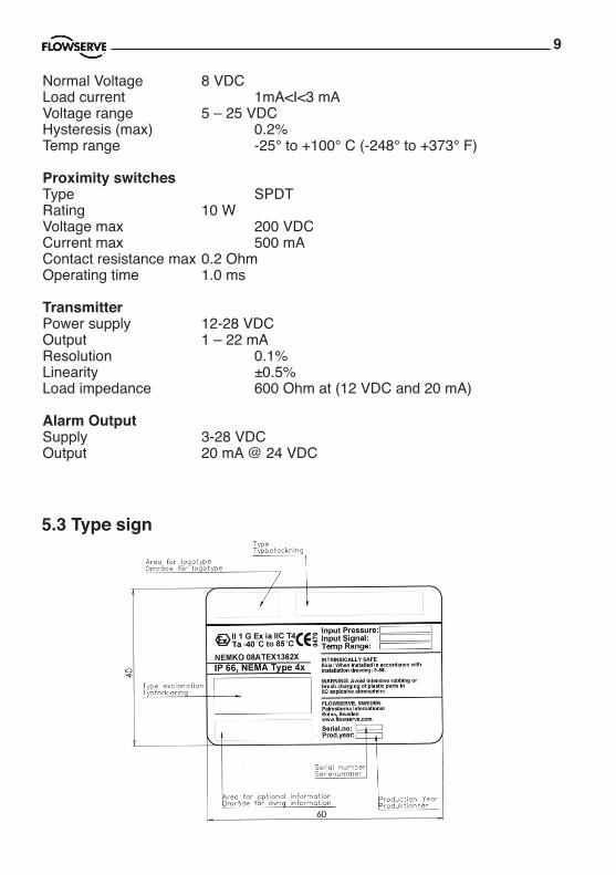
5.3 Type sign
Normal Voltage 8 VDCLoad current 1mA<I<3 mAVoltage range 5 – 25 VDCHysteresis (max) 0.2%Temp range -25° to +100° C (-248° to +373° F)
Proximity switches Type SPDTRating 10 WVoltage max 200 VDCCurrent max 500 mAContact resistance max 0.2 OhmOperating time 1.0 ms
TransmitterPower supply 12-28 VDCOutput 1 – 22 mAResolution 0.1%Linearity ±0.5%Load impedance 600 Ohm at (12 VDC and 20 mA)
Alarm OutputSupply 3-28 VDC Output 20 mA @ 24 VDC
10
5.4 D20 Model Code Ordercode_D20_rev19_100624_aue D20
D20 Compact Digital Positioner Model Code
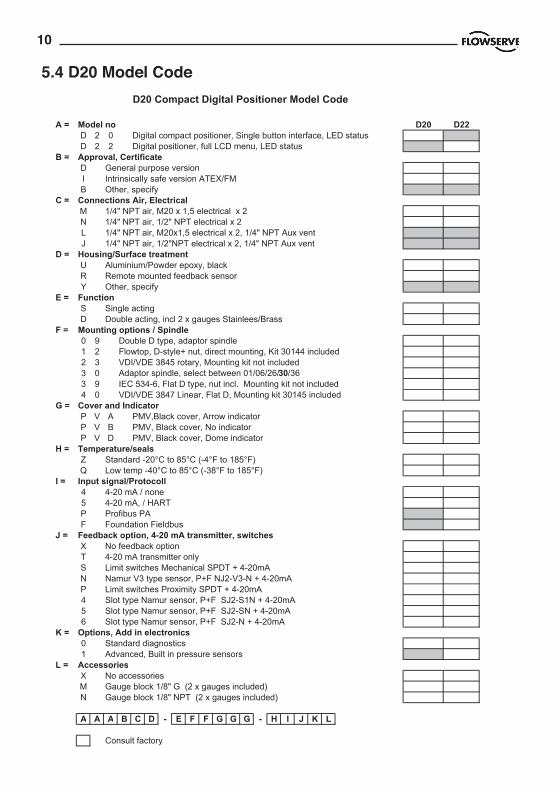
A = Model no D20 D22D 2 0 Digital compact positioner, Single button interface, LED statusD 2 2 Digital positioner, full LCD menu, LED status
B = Approval, CertificateD General purpose versionI Intrinsically safe version ATEX/FMB Other, specify
C = Connections Air, ElectricalM 1/4" NPT air, M20 x 1,5 electrical x 2N 1/4" NPT air, 1/2" NPT electrical x 2 L 1/4" NPT air, M20x1,5 electrical x 2, 1/4" NPT Aux ventJ 1/4" NPT air, 1/2"NPT electrical x 2, 1/4" NPT Aux vent
D = Housing/Surface treatmentU Aluminium/Powder epoxy, black R Remote mounted feedback sensorY Other, specify
E = FunctionS Single actingD Double acting, incl 2 x gauges Stainlees/Brass
F = Mounting options / Spindle0 9 Double D type, adaptor spindle1 2 Flowtop, D-style+ nut, direct mounting, Kit 30144 included2 3 VDI/VDE 3845 rotary, Mounting kit not included 3 0 Adaptor spindle, select between 01/06/26/30/363 9 IEC 534-6, Flat D type, nut incl. Mounting kit not included4 0 VDI/VDE 3847 Linear, Flat D, Mounting kit 30145 included
G = Cover and IndicatorP V A PMV,Black cover, Arrow indicatorP V B PMV, Black cover, No indicatorP V D PMV, Black cover, Dome indicator
H = Temperature/sealsZ Standard -20°C to 85°C (-4°F to 185°F)Q Low temp -40°C to 85°C (-38°F to 185°F)
I = Input signal/Protocoll4 4-20 mA / none5 4-20 mA, / HARTP Profibus PAF Foundation Fieldbus
J = Feedback option, 4-20 mA transmitter, switchesX No feedback optionT 4-20 mA transmitter onlyS Limit switches Mechanical SPDT + 4-20mAN Namur V3 type sensor, P+F NJ2-V3-N + 4-20mAP Limit switches Proximity SPDT + 4-20mA4 Slot type Namur sensor, P+F SJ2-S1N + 4-20mA5 Slot type Namur sensor, P+F SJ2-SN + 4-20mA6 Slot type Namur sensor, P+F SJ2-N + 4-20mA
K = Options, Add in electronics0 Standard diagnostics1 Advanced, Built in pressure sensors
L = AccessoriesX No accessoriesM Gauge block 1/8" G (2 x gauges included)N Gauge block 1/8" NPT (2 x gauges included)
A A A B C D - E F F G G G - H I J K L
Consult factory
2010-07-30 11:48

11
Ordercode_D20E_rev18_100624_aue D20E
D20 Explosion Proof Digital Positioner Model Code
A = Model no D20E D22ED 2 0 Digital compact positioner, Single button interface, LED statusD 2 2 Digital positioner, full LCD menu, LED status
B = Approval, CertificateE Explosion proof ATEX + FM
C = Connections Air, ElectricalG 1/4" G air, M20 x 1,5 electrical x 2M 1/4" NPT air, M20 x 1,5 electrical x 2N 1/4" NPT air, 1/2" NPT electrical x 2
D = Housing/Surface treatmentU Aluminium/Powder epoxy, black R Aluminium/Powder epoxy, black,Remote mounted feedback sensorS Explosion proof Stainless steel enclosure (Connections N only)
E = FunctionS Single acting
F = Mounting options / Spindle0 9 Double D type 6 mm, adaptor spindle (01/06/26/30/36)1 2 D-style+ nut, Flowtop direct mounting2 3 VDI/VDE 3845 rotary, (Mounting kit not included)3 0 Adaptor spindle, select between 01/06/26/30/363 9 IEC 534-6, D style + nut. (Mounting kit not included)
G = Cover CoulorP V B PMV, Black cover, No indicatorF S W Flowserve WhiteF S Y Flowserve Yellow
H = Temperature/sealsZ Standard -20°C to 85°C (-4°F to 185°F)Q Low temp -40°C to 85°C (-38°F to 185°F)
I = Input signal/Protocoll4 4-20 mA / none5 4-20 mA, / HARTP Profibus PAF Foundation Fieldbus
J = Feedback option, 4-20 mA transmitter, switchesX No feedback optionT 4-20 mA transmitter, Alarm output
K = Options, Add in electronics0 Standard diagnostics1 Advanced, Built in pressure sensors
L = AccessoriesX No accessories (gauge ports included)M Gauge block 1/8" G (2 x gauges included)N Gauge block 1/8" NPT (2 x gauges included)
A A A B C D - E F F G G G - H I J K L
Consult factory
2010-07-30 11:50

12
5.5 Control Drawing
UN
CLA
SSIF
IED
AR
EA
Isol
ator
Isol
ator
4+Po
stiti
oner
Ii : 2
9,7m
APi
: 79
mW
Ci :
40
nF
Ui :
10,
6V
HAZ
ARD
EOU
S AR
EA
7+ 6-
Posi
tione
rU
i : 1
0,6V
Pi :
79m
WC
i : 4
0 nF
Li :
100
µH
Ii : 2
9,7m
A
HAZ
ARD
EOU
S AR
EA
3-Li
: 10
0 µH
Pin
3;4
: Sw
itch
1 Pi
n 6;
7 : S
witc
h 2
UN
CLA
SSIF
IED
AR
EA
Pi :
653m
W
D2x
Ixx-
xxxx
xx-x
xTxx
Posi
tione
r
Mod
el n
o: D
3Ixx
-xxx
xxx-
xxTx
/Log
ix 8
xx-0
2-xx
xxxx
-xxx
-xxT
Pin
9;10
4-20
mA
Out
put
UN
CLA
SSIF
IED
AR
EAH
AZAR
DEO
US
AREA
Safe
ty B
arrie
r /PA
/PA
10-
Ii : 9
3mA
Ui :
28V
Li :
11,3
µH
Ci :
16,
4 nF
9+
Ci :
5,6
4 nF
D2x
Ixx-
xxxx
x-xx
Txx
Posi
tione
r
Mod
el n
o: D
3Ixx
-xxx
xxx-
xxTx
/Log
ix 8
xx-0
2-xx
xxxx
-xxx
-xxT
Ala
rm
Pin
11;1
2
/PA
/PA
11+
12-
UN
CLA
SSIF
IED
AR
EA
Safe
ty B
arrie
rU
i : 2
8V
Pi :
315m
WIi
: 45m
A
Li :
11,3
µH
HAZ
ARD
EOU
S AR
EA
Pi :
315m
W
Posi
tione
r
Posi
tione
r
Nor
mal
ly C
lose
d
Pin
7;8
: Sw
itch
2Pi
n 4;
5 : S
witc
h 1
Safe
ty B
arrie
r
3 or
4
5
Pin
3;5
: Sw
itch
1 Pi
n 6;
8 : S
witc
h 2
Nor
mal
ly O
pen
UN
CLA
SSIF
IED
AR
EA
Ui :
28V
Ci :
1 n
F
Ii : 4
5mA
HAZ
ARD
EOU
S AR
EA
Pi :
315m
W
/PA
/PA
/PA
/PA
Safe
ty B
arrie
r
6 or
7
8
UN
CLA
SSIF
IED
AR
EA
Ui :
28V
Ci :
1 n
F
Ii : 4
5mA
Li :
1 µH
HAZ
ARD
EOU
S AR
EA
Li :
1 µH
UN
CLA
SSIF
IED
AR
EA
Posi
tione
r
Posi
tione
r
Pin
7;8
: Sw
itch
2Pi
n 4;
5 : S
witc
h 1
Nor
mal
ly C
lose
d
Pin
6;8
: Sw
itch
2Pi
n 3;
5 : S
witc
h 1
Nor
mal
ly O
pen
Isol
ator
Isol
ator
3 or
4U
i : 1
0,6V
HAZ
ARD
EOU
S AR
EA
5 86 or
7
Pi :
79m
WC
i : 1
nF
Li :
1 µH
Ui :
10,
6VIi
: 29,
7mA
Ci :
1 n
FLi
: 1
µH
Pi :
79m
W
HAZ
ARD
EOU
S AR
EA
Ii : 2
9,7m
A
UN
CLA
SSIF
IED
AR
EA
4
Rem
ote
unit
outp
ut p
aram
eter
Po :
0,38
WPo
sitio
ner
Shie
lded
cab
le le
ss th
an 1
0 m
etre
s
HAZ
ARD
EOU
S AR
EA
Pot.
Pin
3;4;
5 43 553
D3I
xx-x
xxxx
x-xx
6xD
2xIx
x-xx
xxxx
-xx6
xxD
2xIx
x-xx
xxxx
-xx5
xxD
2xIx
x-xx
xxxx
-xx4
xxD
2xIx
x-xx
xxxx
-xxN
xxD
2xIx
x-xx
xxxx
-xxP
xxD
2xIx
x-xx
xxxx
-xxS
xx
All c
ompo
nent
s ne
ed S
afte
y Ba
rrier
s * e
xcep
t the
Sw
itche
s on
tran
smitt
er b
oard
3-A
s81N
, 3-A
s81D
4,
Expl
osio
n H
azar
d - D
o no
t dis
conn
ect e
quip
men
t unl
ess
area
is k
now
n to
be
non-
haza
rdou
s.
Subs
titut
ion
of th
e fo
llow
ing
com
pone
nts
may
impa
ir su
itabi
lity
for D
ivis
ion
2 :
or; r
ead,
und
erst
and
and
adhe
re to
the
man
ufac
ture
r's li
ve m
aint
enan
ce p
roce
dure
s.To
pre
vent
igni
tion
of fl
amm
able
or c
ombu
stib
le a
tmos
pher
es, d
isco
nnec
t pow
er b
efor
e se
rvic
ing,
*Onl
y C
SA a
nd F
M
Subs
titut
ion
of c
ompo
nent
s m
ay im
pair
Intri
nsic
Saf
ety.
War
ning
s:
Non
-Ince
ndiv
e:
Furth
er re
quire
men
ts fo
r FM
:- A
ssoc
iate
d ap
para
tus
man
ufac
ture
r's in
stal
latio
n dr
awin
g m
ust b
e fo
llow
ed w
hen
inst
allin
g th
is e
quip
men
t.- T
he E
ntity
Con
cept
allo
ws
inte
rcon
nect
ions
of i
ntrin
sica
lly s
afe
appa
ratu
s w
ith a
ssoc
iate
d ap
para
tus
whe
n th
e fo
llow
ing
is tr
ue:
V
max
or U
i lar
ger t
han
Voc,
Vt o
r Uo;
Im
ax o
r Ii l
arge
r tha
n Is
c, It
or I
o
Pm
ax o
r Pi l
arge
r tha
n Po
C
a la
rger
than
Ci +
Cca
ble
L
a la
rger
than
Li +
Lca
ble
- Dus
t-Tig
ht c
ondu
it se
al m
ust b
e w
hen
inst
alle
d in
Cla
ss II
and
Cla
ss II
I env
ironm
ents
.- C
ontro
l equ
ipm
ent c
onne
cted
to A
ssoc
iate
d Ap
para
tus
mus
t not
use
or g
ener
ate
mor
e th
an 2
50 V
rms
or V
dc.
- Res
ista
nce
betw
een
Intri
nsic
ally
Saf
e G
roun
d m
ust b
e le
ss th
an 1
,0 O
hm.
- Ins
talla
tion
shou
ld b
e in
acc
orda
nce
with
AN
SI/IS
A-R
P12.
06.0
1 "In
stal
latio
n of
Intri
nsic
ally
Saf
e Sy
stem
s fo
r Haz
ardo
us (C
lass
ified
) Loc
atio
ns" a
nd th
e N
atio
nal
Elec
tric
Cod
e (A
NSI
/NFP
A 70
).- T
he a
ssoc
iate
d ap
para
tus
mus
t be
FM a
ppro
ved.
- The
ass
ocia
ted
appa
ratu
s m
ust b
e a
resi
stiv
ely
limite
d by
a s
ingl
e or
mul
tiple
cha
nnel
FM
App
rove
d As
soci
ated
app
arat
us h
avin
g pa
ram
eter
s le
ss th
an th
ose
quot
ed,
and
for w
hich
the
outp
ut a
nd th
e co
mbi
natio
ns o
f out
put i
s no
n-ig
nitio
n ca
pabl
e fo
r the
Cla
ss, D
ivis
ion
and
Gro
up o
f use
.
Mod
el n
o:
Logi
x 8x
x-02
-xxx
xxx-
xx1-
xxx
D3I
xx-x
xxxx
x-xx
Sx
Mod
el n
o:
Logi
x 8x
x-02
-xxx
xxx-
xx2-
xxx
D3I
xx-x
xxxx
x-xx
Px
Mod
el n
o:
Logi
x 8x
x-02
-xxx
xxx-
xx3-
xxx
D3I
xx-x
xxxx
x-xx
Nx
Mod
el n
o:
Logi
x 8x
x-02
-xxx
xxx-
xx4-
xxx
D3I
xx-x
xxxx
x-xx
4x
Mod
el n
o:
Logi
x 8x
x-02
-xxx
xxx-
xx5-
xxx
D3I
xx-x
xxxx
x-xx
5x
Mod
el n
o:
Logi
x 8x
x-02
-xxx
xxx-
xx6-
xxx
3-As
81D
5, 3
-As8
1D6,
3-A
s81P
, D3-
As38
E N
, D3-
As38
E D
4, D
3-As
38E
D5,
D3-
As38
E D
6 an
d D
3-As
38E
P.Pi
n 2:
Irtn
Posi
tione
r
/PA
Safe
ty B
arrie
r /PA
Pin
1;2
1+ 2-
HAZ
ARD
EOU
S AR
EA
Ui :
28V
Ii : 9
3mA
Pi :
653m
WC
i : 1
1,3
nFLi
: 11
,3 µ
H
Pin
1: Is
rc
UN
CLA
SSIF
IED
AR
EA
µH c
hang
ed to
µH; C
i: 35
nF
chan
ged
to C
i: 40
nF.
8. S
witc
h 2
CO
M
1. In
put s
igna
l
12. A
larm
Out
put -
11. A
larm
Out
put +
10. 4
-20
mA
-
9. 4
-20
mA
+
7. S
witc
h 2
NC
6. S
witc
h 2
NO
5. S
witc
h 1
CO
M
4. S
witc
h 1
NC
3. S
witc
h 1
NO
2. In
put s
igna
l
4-20
mA
inpu
t sig
nal
Mec
hani
cal o
r Pro
xim
ity s
witc
hes
NA
MU
R s
witc
hes
D3I
xx-x
xxxx
x-xx
4x/L
ogix
8xx
-02-
xxxx
xx-x
xx-x
x4
Mod
el n
o: D
3Ixx
-xxx
xxx-
x4xx
/Log
ix 8
1x-0
2-xx
xxxx
-xxx
-xxx
Mod
el n
o: D
3Ixx
-xxx
xxx-
xxN
x/Lo
gix
8xx-
02-x
xxxx
x-xx
x-xx
3
D3I
xx-x
xxxx
x-x5
xx/L
ogix
82x
-02-
xxxx
xx-x
xx-x
xx
D3I
xx-x
xxxx
x-xx
5x/L
ogix
8xx
-02-
xxxx
xx-x
xx-x
x5D
3Ixx
-xxx
xxx-
xx6x
/Log
ix 8
xx-0
2-xx
xxxx
-xxx
-xx6
Mod
el n
o: D
3Ixx
-xxx
xxx-
xxSx
/Log
ix 8
xx-0
2-xx
xxxx
-xxx
-xx1
D3I
xx-x
xxxx
x-xx
Px/L
ogix
8xx
-02-
xxxx
xx-x
xx-x
x2
Mod
el n
o: D
3Ixx
-Mxx
xxx-
xxxx
/Log
ix 8
xx-0
2-xx
xxxx
-xM
x-xx
xD
3Ixx
-Pxx
xxx-
xxxx
/Log
ix 8
xx-0
2-xx
xxxx
-xPx
-xxx
to th
e N
otif
ied
body
D3I
xx-R
xxxx
x-xx
xx/L
ogix
8xx
-02-
xxxx
xx-x
Rx-
xxx
D3I
xx-Q
xxxx
x-xx
xx/L
ogix
8xx
-02-
xxxx
xx-x
Qx-
xxx
D2x
Ixx-
xxxx
xx-x
4xxx
D2x
Ixx-
xxxx
xx-x
xNxx
D2x
Ixx-
xxxx
xx-x
xSxx
D2x
Ixx-
xxxx
xx-x
5xxx
D2x
Ixx-
xxxx
xx-x
x4xx
D2x
Ixx-
xxxx
xx-x
x6xx
D2x
Ixx-
xxxx
xx-x
x5xx
D2x
Ixx-
xxxx
xx-x
xPxx
D3I
xx-x
xxxx
x-xx
Px/L
ogix
8xx
-02-
xxxx
xx-x
xx-x
x2
D2x
Ixx-
xxxx
xx-x
xPxx
D2x
Ixx-
xxxx
xx-x
xSxx
Mod
el n
o: D
3Ixx
-xxx
xxx-
xxSx
/Log
ix 8
xx-0
2-xx
xxxx
-xxx
-xx1
Mec
hani
cal o
r Pro
xim
ity s
witc
hes
D2x
IxR
-xxx
xxx-
xxxx
x
No
mod
ific
atio
n pe
rmitt
ed w
ithou
t ref
eren
ce
7
Test
ed a
ccor
ding
to w
ithst
and
diel
ectri
c st
reng
th re
quire
men
t IEC
EN
600
79-1
1 6.
3.12
Ingr
ess
Prot
ectio
n IP
66,
NEM
A 4X
Sche
dule
dra
win
g
55
55
5
5 5
5
55
5
5 55
5
5
5
5
5
7
Rem
ote
unit
5 5
6
7
5
6
77
77
77
7 7 7 7
7 7 7 7 7 7
7
Always see www.pmv.nu for latest revision.
13
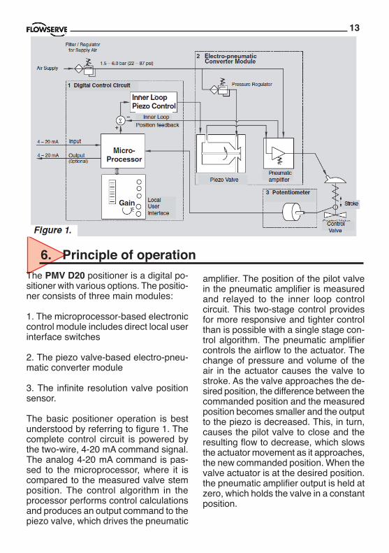
amplifier. The position of the pilot valve in the pneumatic amplifier is measured and relayed to the inner loop control circuit. This two-stage control provides for more responsive and tighter control than is possible with a single stage con-trol algorithm. The pneumatic amplifier controls the airflow to the actuator. The change of pressure and volume of the air in the actuator causes the valve to stroke. As the valve approaches the de-sired position, the difference between the commanded position and the measured position becomes smaller and the output to the piezo is decreased. This, in turn, causes the pilot valve to close and the resulting flow to decrease, which slows the actuator movement as it approaches, the new commanded position. When the valve actuator is at the desired position. the pneumatic amplifier output is held at zero, which holds the valve in a constant position.
6. Principle of operation
Piezo Valve
Inner LoopPosition feedback
Pneumaticamplifier
Control Valve
LocalUserInterface
Inner LoopPiezo Control
Micro-Processor
3 Potentiometer
1 Digital Control Circuit
Gain
Figure 1.
The PMV D20 positioner is a digital po-sitioner with various options. The positio-ner consists of three main modules:
1. The microprocessor-based electronic control module includes direct local user interface switches
2. The piezo valve-based electro-pneu-matic converter module
3. The infinite resolution valve position sensor.
The basic positioner operation is best understood by referring to figure 1. The complete control circuit is powered by the two-wire, 4-20 mA command signal. The analog 4-20 mA command is pas-sed to the microprocessor, where it is compared to the measured valve stem position. The control algorithm in the processor performs control calculations and produces an output command to the piezo valve, which drives the pneumatic

14
7.1 GeneralBefore starting installation, inspect the digital positioner for any transit damages. The PMV D20 positioner is installed with a mounting kit (according to NAMUR specification) to the left-hand actuator support rod.
Generally, the unit can be installed in any mounting position. The stroke feed-back is realized by a follower arm and stem clamps.
The mounting of rod actuators (according to NAMUR) is described in Figure 3.
For the two mounting possibilities of cast yoke actuators (according to NAMUR, lEC 534 part 6) refer to Figure 5.
After installation, ensure all screw con-nections are tightened correctly and all moving parts are free from excessive friction.
7. Mounting and installation
NOTE!All products that are covered by an ATEX Certification number ending with an “X”, special care must be taken when cleaning the surface of the product.“The enclosure must be cleaned with a damp cloth due to static electricity for plastic windows/surfaces”
For securing covers and lids, it’s important to use the correct torque:
Product Size (screw) Torque Nm D20 M4 0,65 Nm +/- 15%
Covers (thread on) for D20EX, tighten fully and secure.

15
7.2 Dimensional drawings
16
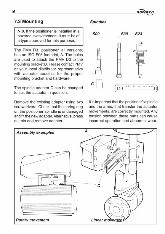
7.3 Mounting
N.B. If the positioner is installed in a hazardous environment, it must be of a type approved for this purpose.
The PMV D3 positioner, all versions, has an ISO F05 footprint, A. The holes are used to attach the PMV D3 to the mounting bracket B. Please contact PMV or your local distributor representative with actuator specifics for the proper mounting bracket and hardware.
The spindle adapter C can be changed to suit the actuator in question.
Remove the existing adapter using two screwdrivers. Check that the spring ring on the positioner spindle is undamaged and fit the new adapter. Alternative, press out pin and remove adapter.
It is important that the positioner’s spindle and the arms, that transfer the actuator movements, are correctly mounted. Any tension between these parts can cause incorrect operation and abnormal wear.
Assembly examples A B
C
Rotary movement Linear movement
Spindles
S09 S39 S23
C

17
Mounting of the PMV D20 positioner on a linear pneumatic actuator (NAMUR / IEC 534 part 6)(See Figure 1)
The mounting of a rod actuator kit (ac-cording to IEC 534 part 6) is described in an example by using the following equipment:Valve: Standard globe valve or equiva-lentActuator: Single-acting pneumatic ac-tuatorPositioner: PMV D20 with NAMUR mounting kit.
Pre-assembly: Valve with actuator (valve stroke is matched with the actuator stroke).
For mounting, proceed as follows:
Mounting the Follower Arm (Figures 1 and 2)1. Unscrew the lock nut for the follower arm attachment.2. Place the follower arm on the shaft at the back of the positioner and fasten it with the lock nut. The follower pin should point back from the positioner.
CAUTION: Maximum torque 0,25 Nm (0,18 ft-lbs).
Mounting the stem clamp bracket and take-off arm (Figure 1)1. Attach the stem clamp bracket to the stem clamp and fasten it with two hexa-gon socket screws and lock washers.
2. Attach the take off arm to the stem clamp bracket and fasten it with a hexa-gon socket capscrew and a washer. En-sure the take-off arm slot is centered.
Figure 2. Follower Arm (standard)
Follower pin
Washer Nut Follower arm
Figure 1. Mounting on a Rod Actuator(IEC 534 part 6)
18
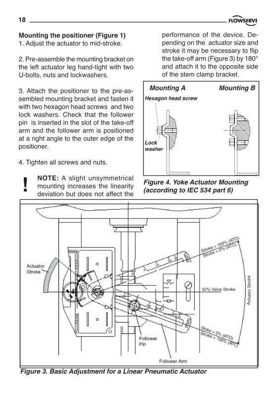
Mounting the positioner (Figure 1)1. Adjust the actuator to mid-stroke.
2. Pre-assemble the mounting bracket on the left actuator leg hand-tight with two U-bolts, nuts and lockwashers.
3. Attach the positioner to the pre-as-sembled mounting bracket and fasten it with two hexagon head screws and two lock washers. Check that the follower pin is inserted in the slot of the take-off arm and the follower arm is positioned at a right angle to the outer edge of the positioner.
4. Tighten all screws and nuts.
NOTE: A slight unsymmetrical mounting increases the linearity deviation but does not affect the
Figure 3. Basic Adjustment for a Linear Pneumatic Actuator
performance of the device. De-pending on the actuator size and stroke it may be necessary to flip the take-off arm (Figure 3) by 180° and attach it to the opposite side of the stem clamp bracket.
Mounting A Mounting B
Figure 4. Yoke Actuator Mounting (according to IEC 534 part 6)
Hexagon head screw
Lock washer
!

19
Follower pin adjustment (Figure 3)The positioner follower pin must be ad-justed to match the valve stroke in the following manner:
1. Adjust the follower pin (STROKE + 10 mm) as indicated on the follower arm’s embossed scale (Figure 2).
2. Exhaust the actuator.
3. Loosen the follower pin and shift it along the follower arm until the control marking on the feedback gear (Figure 4) is horizontal (points to the center of the feedback potentiometer). Fasten the follower pin in this position.
4. Adjust the actuator to full stroke and check the follower pin adjustment the same way as described in step 3. As the actuator strokes, the rotation of the feedback gear should be between the inner control markings. If the length of rotation is outside the control markings, adjust the follower pin farther out on the feedback lever to reduce the angle of rotation.
NOTE: Stroke the actuator carefully and ensure the follower arm does not interfe-re with valve parts, actuator or positioner. Do not adjust the follower pin too near to the slot end of the take-off arm.
The minimum lateral distance should be approximately 5 mm (0,2 inches) to prevent bending of the feed-back me-chanisim.
Figure 5. Direct mounting to actuatorRotary actuatorsMounting the PMV D20 positioner on a quarter-turn actuator (closed or open by spring)The mounting of a pneumatic double-piston part-turn valve actuator (in accor-dance with VDI/VDE 3845) is described as an example by using the following equipment:
Quarter-turn valve actuator: Rack & pinion or scotch yoke, closed or open by spring.

20
Rotary actutaors VDI/VDE 3485 (Namur)
Mount bracket 1 to positioner. Secure with 4 x M6 screws 2.
Fit positioner on actuator and secure with 4 x screws 3.
Install tubing 4 between actuator and positioner. See section 7.
Linear actuator “Flow act” (Direct mounting, integrated tubing.
Check O-rings, Install bracket 1 to posi-tioner and secure with screws.
Fit pin on valve stem.
Fit lever arm to positioner shaft.
Fit and check O-rings and positioner to actuator and secure with 2 x screws 2.
No tubing needed, it’s integrated with actuator, fit plug in positioner out port.
Linear actuator VDI/VDE 3847 (Direct mounting, integrated tubing.
Check O-rings, Install bracket1 to positioner and secure with 2 x screws 2.
Fit pin on valve stem.
Fit lever arm to positioner shaft.
Fit and check O-rings and positioner to actuator and secure with 2 x screws 3.
No tubing needed, it’s integrated with actuator.
12
3
4
1
2
1
2
3

21
Figure 6. Mounting a Part-turn Valve Actuator in acc. with VDI/VDE3845
1
2 3
After mounting has been completed, tube the positioner to the actuator using the appropriate compression fitting con-nectors:Air connections: 1/4” NPT (standard air connection).Auxiliary power: Pressurized air or per-missible gases, free of moisture and dust in according with IEC 770 or ISA 7.0.01.Pressure range: 1,5 – 6 bar (30 – 90 psi).For connecting the air piping, the fol-lowing notes should be observed:1. The positioner passageways are equipped with filters, which remove medium and coarse size dirt from the pressurized air. If necessary, they are easily accessible for cleaning.
2. Supply air should meet IEC 770 or ISA 7.0.01 requirements. A coalescing filter should be installed in front of the supply air connection (Figure 8). Now
Mounting the positioner (Figure 6)Place the positioner (1) onto the moun-ting block (2) of the actuator using four screws (3) Ensure the coupler fits on to
the shaft of the quarter-turn connection on the part-turn valve actuator.
connect the air supply to the filter, which is connected to the PMV D20 positioner.
3. With a maximum supply pressure of 6 bar (102 psi) a regulator is not requi-red.
4. With an operating pressure of more than 6 bar (90 psi), a reducing regulator is required.
The flow capacity of the regulator must be larger than the air consumption of the positioner (7 Nm3 /h @ 6 bar / 4,12 scfm @ 90 psi).5. Connect the outlet connector (Figure 7) of the positioner with tubing, indepen-dent of the action (direct or reverse).
8. Tubing positioner to actuator

22
Connect the 4-20 mA current source to terminals +1 and -2, see connection table.
9.1 Grounding screwThe grounding screw, located inside the positioner cover, should be used to pro-vide the unit with an adequate and relia-ble earth ground reference. This ground should be tied to the same ground as the electrical conduit. Additionally, the elec-trical conduit should be earth grounded at both ends of its run. The grounded scrrew must not be used to termingate signal shield wires.
Electrical connections: signal cable with cable passage (1/2” NPT, or M20 x 1,5) to terminals 2 x 2,5 mm.
Input signal: 4 – 20 mA
NOTE: Observe the minimum require-ments of voltage and equivalent electrical load:
8 VDC at 20 mA non HART version9,4 VDC at 20 mA HART version
The performance is ensured only for a minimum input current of 3,6 mA.
For wiring, the following notes should be observed:
NOTE: The input loop current signal to the PMV D20 should be in shielded cable. Shields must be tied to a ground at only one end of the cable to provide a place for environmental electrical noise to be removed from the cable. In general, shield wire should be connected at the source. (Figure 7).
9. Wiring and grounding guidelines
Connection Description +1 Input +4-20 mA –2 Input –4-20 mA
Pneumatic output signal (outlet) Air supply
2 - 6 bar30 - 90 Psi5 µ
ISO 8573 2.2.2ISA 7.0.01.-1996 Class 2

23
The PMV D20 digital positioner has been designed to operate correctly in elec-tromagnetic (EM) fields found in typical industrial environments. Care should be taken to prevent the positioner from being used in environments with exces-sively high EM field strengths (greater than 10 V/m). Portable EM devices such as hand-held two-way radios should not be used within 30 cm of the device.
Ensure proper wiring and shielding techniques of the control lines, and route
control lines away from electro-magne-tic sources that may cause unwanted noise.
An electromagnetic line filter can be used to further eliminate noise.
In the event of a severe electrostatic discharge near the positioner, the device should be inspected to ensure correct operability. It may be necessary to reca-librate the PMV D20 positioner to restore operation.
9.2 Electromagnetic compatibility
Figure 7. Connections
HART-connection
+ – + – + –
1 2 3 4 5 9 10 11 12
Remote unit
Option
Explosion Proof with LCD1 – Input Signal, +4-20mA, HART2 – Input Signal, -4-20mA, HART3 – Remote4 – Remote5 – Remote6 – 4-20 mA + Feedback, 13-28 V dc7 – 4-20 mA – Feedback, 12-28 V dc8 – Alarm output +, 8-28 V dc9 – Alarm output -, 8-28 V dc
Explosion Proof with LED’s1 – Input Signal, +4-20 mA, HART2 – Input Signal, -4-20 mA, HART3 – Remote4 – Remote5 – Remote6 – 4-20 mA + Feedback, 13-28 V dc7 – 4-20 mA – Feedback, 13-28 V dc
General Purpose and Intrinsically Safe1– Input Signal, +4-20mA, HART2– Input Signal, -4-20mA, HART3 – Switch 1 output/ Remote4 – Switch 1 output/ Remote5 – Switch 1 output/ Remote6 – Switch 2 output/ Remote7 – Switch 2 output/ Remote8 – Switch 2 output/ Remote9 - 4-20 mA + Feedback, 13-28 V DC10 - 4-20 mA - Feedback, 13-28 V DC11 - Alarm output +, 8-28 V DC12 - Alarm output -, 8-28 V DC

24
Example: DCS Compliance Voltage = 19 V Rbarrier = 300Ω Rwire = 25Ω CURRENTMAX = 20 mA Voltage = 19 V – 0.020 A(300Ω + 25Ω) = 12.5 V
This system will support the PMV D20, as the voltage 12.5 V is greater than the required 8 VDC for non-HART and 9.4 VDC for HART.
9.3 Compliance voltage Output compliance voltage refers to the voltage limit the current source can provide. A current loop system consists of the current source, wiring resistance, barrier resistance (if present), and the PMV D20 impedance. The PMV D20 requires that the current loop system allow for a 8.0 - 9.4 VDC drop across the positioner at maximum loop current.
CAUTION: Never connect a vol-tage source directly across the positioner terminals. This could cause permanent circuit board damage.
In order to determine if the loop will sup-port the PMV D20, perform the following calculation:
Figure 9. Compliance voltage
Voltage = Compliance Voltage(@Cur-rentMAX)
– CurrentMAX(Rbarrier + Rwire)
To support the PMV D20 the calculated voltage must be greater than 9.4 VDC for D20 HART and 8 VDC for non-HART.

25
10. Operation D20
Calibration button
ALARMOPEN/CLOSEDCONTROLLING
10.1 GeneralThe D20 is operated by the yellow button. Depending on desired action, press the button:- during a number of seconds (Ex: )or- a number of times. (Ex: )
All operation steps are indicated by lit or flashing LED(s).
10.2 StartupConnect Air supply and a mA-simulator to the positioner.
Warning: During calibration, the actuator may stroke unexpec-tedly.
10.3 CalibrationApply 4 mA current as input signal.
Press the button for 5 sec. (Re-lease the button when the three LED:s start to flash alternately). The calibration starts, the actuator goes go to max. and min. position and calculates the control parameters.
The Calibration procedure will take between 30 seconds and some minutes depending on actuator size.
The three LED:s will flash alternately during calibration.
After calibration all the three LED:s are lit for a moment.
A successfull calibration is indicated by yellow or green LED:
Green LED flashes = In service
Yellow LED flashes = In service.The unit vents in max or min po-sition.
An unsuccessfull calibration is indicated by error codes:
D20 does not reach the setpoint.
For other indications, see Error codes, page 46.
5 sec.
G
Y
R
5 sec.
x3
Calibration button

26
x3
10.4 Set of Direct or Reverse action Note! For safety reason, this opera-tion has to be done max 5 minutes af-ter calibration. If time has run out, or if power is disconnected during the five minutes, perform a new cali-bration, before changing the direction.
Run 4 mA. If valve is in right position, then check the position over the whole range (8, 12, 16 and 20 mA).
If the direction need to be changed: press the button 3 times and the direction will change.
Check operation at 4 – 8 – 12 – 16 and 20 mA
10.5 Show gain settingIf the actuator position is unstable or selfoscillating after calibration, the gain can be adjusted.
Gain can be set from A (lowest) to G (highest). Default is D.
To show the current gain setting, press the buttonfour times.
To indicate the current setting, the LEDs flashes according to the following:
LEDs show: G (Highest)
LEDs show: F
LEDs show: E
LEDs show: D Defaul
LEDs show: C
LEDs show: B
LEDs show: A (Lowest)
The gain code sequence is repeated 5 times.
x4
Y R R
Y R Y
Y R G
Y G
Y G G
Y G Y
Y G R

27
Button functions:
Press 5 sec = Calibration
Press x3 = Direct/reverse action
Press x4 = Show gain setting
Press x5 - x11 = Change gain setting
To indicate that a command isaccepted, the three LED:s light up.
10.6 Change of gain settingTo lower the gain, press the button: 7, 6 or 5 times (5= lowest). To increase the gain (if actuator is mo-ving to slow). Press the button: 9, 10 or 11 times (11= highest) to increase the gain.
The LED:s flashes alternately when the button is pressed. After gain change the LED:s show the gain code (see 9.3) five times.
The default value after first calibration is D .
After this, the gain settings are finis-hed.
x11 G (Highest)
x10 F
x9 E
x8 D Default
x7 C
x6 B
x5 A (Lowest)
Low
er
Hig
her ➾
➾

28
11. Operation D22
11.1 Menus and pushbuttonsThe positioner is controlled using the five pushbuttons and the display, which are accessible when the aluminium cover is removed.For normal functioning, the display shows the current value. Press the ESC button for two seconds to display the main menu.
Use the pushbuttons to browse through the main menu and the sub-menus.
The main menu is divided up into a basic menu and a full menu, see page 30.
11.2 Other functionsESCExit the menu without making any chan-ges (as long as any changes have not been confirmed with OK).
FUNCTo select function and change parame-ters.
OKTo confirm selection or change of pa-rameters.
MENU INDICATORDisplays the position of the current menu row in the menu.
ESC FUNC
OK
BASIC MENUMAN/AUTO
OUT OF SERVICE MANUAL
UNPROTECTED
IN SERVICEThe positioner is following the input sig-nal. This is the normal status when the positioner is working.
OUT OF SERVICEThe positioner is not following the in-put signal. Critical parameters can be changed.
MANUALThe positioner can be adjusted manu-ally using the pushbuttons. See section ”Man/Auto”, page 35”.
UNPROTECTEDMost of the parameters can be changed when the positioner is in the ”Unprotec-ted” position. However, critical parame-ters are locked when the positioner is in the ”In service” position.

29
11.3 Menu indicatorThere are indicators at both sides of the display window and they indicate as follows:
Flashing in position Out of service
Flashing in position Manual
Displayed in position Unprotected
The indicators on the right-hand side show the position in the current menu.
11.4 MenusTo display the menus you can select:
- Basic menu, which means you can browse through four different steps
- Full menu, which comprises ten steps. Use the Shift Menu to browse through the steps
Full Menu can be locked out using a passcode.
The main menus are shown on the next page and the sub-menus on the subse-quent pages.
FULL MENUCALIBRATE
FULL MENUMAN/AUTO
FULL MENUSHIFT MENU
11.5 Changing parameter valuesChange by pressing until the desired figure is flashing.
Press to step to the desired figure. Confirm by pressing OK.
A change can be undone by pressing the ESC button, which returns you to the previous menu.

30
BASIC MENUREAD
BASIC MENUMAN/AUTO
BASIC MENU CALIBRATE
BASIC MENUSHIFT MENU
FULL MENUREAD
FULL MENUMAN/AUTO
FULL MENU CALIBRATE
FULL MENUSHIFT MENU
FULL MENUSTATUS
FULL MENU SETUP
FULL MENUTUNING
FULL MENUALARMS
FULL MENUFACT SET
11.6 Menu system
The menus are descri-bed on the following pages.

31
BASIC MENUCALIBRATE
11.7 First startCalibrate in the basic menu is displayed automatically the first time the power is applied, and can be selected from the basic/main menu at any later time.
A complete auto-calibration takes about 2 minutes and includes end limit cali-bration, auto-tuning and a check on the speed of movement. Start the automatic calibration by selecting Auto-Cal and then answer the questions on the dis-play by pressing OK or the respective arrow. The menu is described on the next page.
Calibration error messagesIf a fault occurs during calibration, one of the following error messages can be displayed:
No movement/press ESC to abortTypically the result of an air delivery issue to the actuator, or incorrect moun-ting and/or linkage arrangement. Check for proper supply air to the positioner, pinched tubing, proper actuator sizing, proper linkage and mounting arrang-ement.
Pot uncalibrated/press ESC to abortThe potentiometer has been set to an illegal value. The potentiomenter is alig-ned using the Calibrate - Expert cal - pot Menu. The calibration sequence must be restarted after the fault is corrected.

32
The contents of the menu are shown on the next page. The various menu texts are described below.
Auto-Cal Auto-tuning and calibration of end positions Start tune Starts the tuning. Questions/commands are display-ed during calibration. Select the type of movement, func-tion, etc. with and confirm with OK as shown in the chart on the next page. Lose prev value? OK? A warning that the value set previously will be lost (not during the first auto-tuning). Direction?direct Select for direct function. Direction? reverse Select for reverse function.
In service? Press OK Calibration finished. Press OK to start positioner functioning. (If ESC is pressed, the positioner assumes the ”Out of service” position but the calibration is retained).
TravelCal Calibration of end positions Start cal Start end position calibration. Lose prev value? OK? A warning that the previously set value will be lost. Confirm with OK. The calibration sequence starts. In service? Press OK Calibration finished. Press OK to start positioner functioning. (If ESC is pressed, the positioner assumes the ”Out of service” position but the calibration is retained).
Perform Setting gain Normal A, B, C, D, E, F, G Gain setting depending on actuator size. See page 29.
BASIC MENUCALIBRATE

33
Set point LO: Use the calibrator set to 4 mA (or set another value on the display). Press OK.
Set point HI: Use a calibrator of 20 mA (or set another value on the display). Press OK.
Transmitter: Connect 10 - 28VDC. Connect an external mA meter to the loop. Read low value on mA meter and adjust with up/down key. Press OK to set low value. Repeat procedure to set High value. Also see video on www.pmv.nu
Pot: Potentiometer setting, see section 8. Also see video on www.pmv.nu
Full reset: Resets all set values.
OptionalPressure LO: Use a supply of 2 bar (30 psi) (or set another value on the display). Press OK.Pressure read out only possible on PMV D3with built in pressure sensor.
Pressure HI: Use a supply of 7 bar (105 psi)(or set another value on the display). Press OK.Pressure read out only possible on PMV D3 with built in pressure sensor.
ExpertCal

34
BASIC MENUREAD
Current values can be read using the Read Menu and some values can be reset.
Statisticsn cycles
Statisticsacc travel
Statisticsmean dev
Statisticsmean abs. dev
Statisticsruntime
Statistics# of resets
Statisticsextr. temp
Statisticshistogram
Pos Shows current position
Set&pos Set point and position
Set&dev Set point and deviation
Temp Shows current tempera-ture
Statistics n cycles Shows number of movements (turns)
Acc travel Shows accumulated movement
mean dev Shows accumulated deviation in %
mean abs. Shows absolute dev deviation in % runtime Shows accumulated runtime since last reset
# of resets Shows number of resets done
Extr temp Shows extreme min and max temperature
Histogram Shows position and time for PV
Alarms Displays tripped alarms
The menu contents are shown in the figures on the right and the texts are described below:
StatisticsReset stat
Reset statyes
Reset statno
READpos
READset&pos
READset&dev
READtemp
READStatistics
READAlarms
35
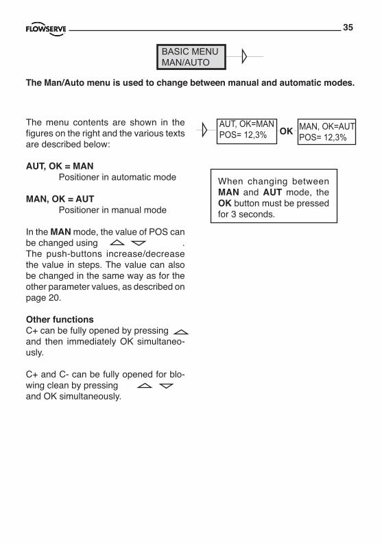
BASIC MENUMAN/AUTO
AUT, OK=MANPOS= 12,3% OK MAN, OK=AUT
POS= 12,3%The menu contents are shown in the figures on the right and the various texts are described below:
AUT, OK = MAN Positioner in automatic mode
MAN, OK = AUT Positioner in manual mode
In the MAN mode, the value of POS can be changed using . The push-buttons increase/decrease the value in steps. The value can also be changed in the same way as for the other parameter values, as described on page 20.
Other functionsC+ can be fully opened by pressing and then immediately OK simultaneo-usly.
C+ and C- can be fully opened for blo-wing clean by pressing and OK simultaneously.
When changing between MAN and AUT mode, the OK button must be pressed for 3 seconds.
The Man/Auto menu is used to change between manual and automatic modes.
36
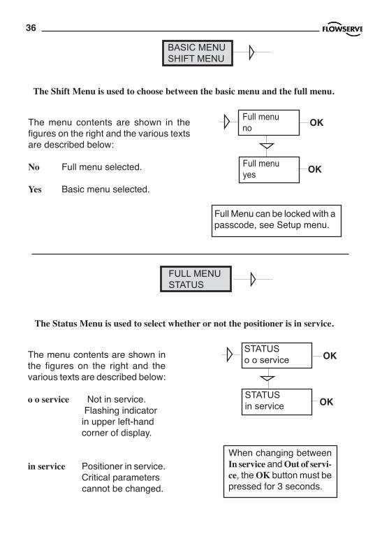
FULL MENUSTATUS
OK
OK
STATUSo o service
The Status Menu is used to select whether or not the positioner is in service.
The menu contents are shown in the figures on the right and the various texts are described below:
o o service Not in service. Flashing indicator in upper left-hand corner of display.
in service Positioner in service. Critical parameters cannot be changed.
When changing between In service and Out of servi-ce, the OK button must be pressed for 3 seconds.
STATUSin service
BASIC MENUSHIFT MENU
Full menuno OK
Full menuyes OK
The Shift Menu is used to choose between the basic menu and the full menu.
The menu contents are shown in the figures on the right and the various texts are described below:
No Full menu selected.
Yes Basic menu selected.
Full Menu can be locked with a passcode, see Setup menu.

37
Actuator Type of actuator Size of actuator Time out Rotating Rotating actuator. Small 10 s Linear Linear actuator. Medium 25 s Large 60 s Texas 180 s Lever Only for linear actuator. Lever stroke Stroke length to achieve correct display. Level cal Calibration of positions to achieve correct display.
Direction Direct Direct function (signal increase opens). Indicator/spindle rotates counter-clockwise. Reverse Reverse function.
Character Curves that show position as a function of input signal. Linear Equal % See diagram. Quick open Sqr root Custom Create own curve.
Cust chr # of point Specify number of points (3, 5, 9, 17, or 33) Cust curve Enter values on X and Y axes.
Curr range 0%=4.0 mA 100%=20.0 mA Possibility of selecting which input signal values will correspond to 0% and 100% movement respectively. Examples of settings: 4 mA = 0%, 12 mA = 100%, 12 mA = 0%, 20 mA = 100%.
FULL MENUSETUP
The Setup Menu is used for various settings.
The menu contents are shown in the chart on the next page and the various texts are described below:
QoSqrLinEq%
Signal
Mov
emen
t
x
y
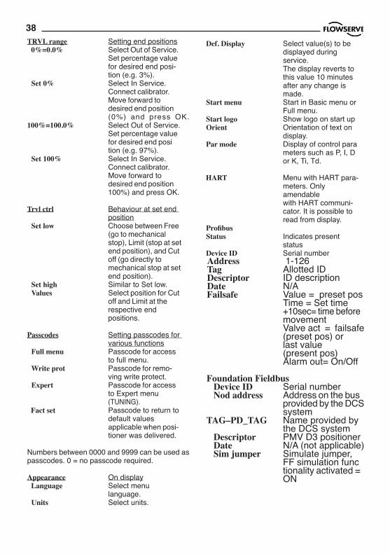
38TRVL range Setting end positions 0%=0.0% Select Out of Service. Set percentage value for desired end posi- tion (e.g. 3%). Set 0% Select In Service. Connect calibrator. Move forward to desired end position (0%) and press OK. 100%=100.0% Select Out of Service. Set percentage value for desired end posi tion (e.g. 97%). Set 100% Select In Service. Connect calibrator. Move forward to desired end position 100%) and press OK.
Trvl ctrl Behaviour at set end position Set low Choose between Free (go to mechanical stop), Limit (stop at set end position), and Cut off (go directly to mechanical stop at set end position). Set high Similar to Set low. Values Select position for Cut off and Limit at the respective end positions.
Passcodes Setting passcodes for various functions Full menu Passcode for access to full menu. Write prot Passcode for remo- ving write protect. Expert Passcode for access to Expert menu (TUNING). Fact set Passcode to return to default values applicable when posi- tioner was delivered.
Numbers between 0000 and 9999 can be used as passcodes. 0 = no passcode required.
Appearance On display Language Select menu language. Units Select units.
Def. Display Select value(s) to be displayed during service. The display reverts to this value 10 minutes after any change is made. Start menu Start in Basic menu or Full menu. Start logo Show logo on start up Orient Orientation of text on display. Par mode Display of control para meters such as P, I, D or K, Ti, Td.
HART Menu with HART para- meters. Only amendable with HART communi- cator. It is possible to read from display. Profibus Status Indicates present status Device ID Serial number Address 1-126 Tag Allotted ID Descriptor ID description Date N/A Failsafe Value = preset pos Time = Set time +10sec= time before movement Valve act = failsafe (preset pos) or last value (present pos) Alarm out= On/Off
Foundation Fieldbus Device ID Serial number Nod address Address on the bus provided by the DCS system TAG–PD_TAG Name provided by the DCS system Descriptor PMV D3 positioner Date N/A (not applicable) Sim jumper Simulate jumper, FF simulation func tionality activated = ON

39
FULL MENUTUNING
Close time Minimum time (Min 0.005) from fully open to closed.Open time Minimum time (Min 0.05) from closed to fully open.Deadband Setting deadband. Min. 0.2%.
Expert Advanced settings.Control See explanations below. Togglestep Test tool for checking functions. Overlays a square wave on the set value. Self test Internal test of processor, potentiometer, etc.
Leakage Air leakage in actuator/tubing can be compensated by settings.
Undo You can read last 20 changes.
The menu contents are shown in the chart on the next page and the various texts are described below:
P, I, D and K, Ti, Td parameters If one of the gains is changed, the cor-responding value in the other gain set is changed accordingly.
Spring adjustThe spring adjust function compensates the airflow linearly with the actuator C+ chamber volume (for a constant position error), so that low volumes get less flow. This is needed for linear single-acting actuators, where a low C+ volume means that the actuator spring is extended, its force is reduced, and less flow is needed for stable position changes.

40
FULL MENUALARMS
Deviation Alarm generated when deviation occursOn/Off Alarm on/off.Distance Allowed distance before alarm is generated.Time Total deviation time before alarm is generated.Alarm out Select ON/OFF offers output on terminals.
Valve act Behaviour of valve when alarm is generated.
Limit 1 Alarm above/below a certain level.On/Off Alarm on/off.Minipos Setting of desired min. position.Maxpos Setting of desired max. position. See diagram below!Hysteresis Desired hysteresis.Alarm on Select ON/OFF offers output on terminals.Valve act Behaviour of valve when alarm is generated.
Limit 2 See Limit 1.
The menu contents are shown in the chart on the next page and the various texts are described below:
Limit 1, maxHysteresis
Limit 2, maxHysteresis
HysteresisLimit 2, min
HysteresisLimit 1, min
0%
100%Alarm Limit 1 on
Alarm Limit 2 on
Alarm Limit 1 off
Alarm Limit 2 off
Alarm Limit 2 on
Alarm Limit 1 onAlarm Limit 1 off
Alarm Limit 2 off
Trav
el
Set alarm and hysteresis values

41
- Valve act
No action Alarm generated only. Operations no affected.
Goto open C+ gives full pressure and valve moves to fully open position. Positioner changes to position Manual.
Goto close C- gives full pressure and valve moves to fully clo sed position. Positioner changes to position Manual.
Manual Valve stays in unchanged position. Positioner mo- ves to position Manual.
Temp Alarm based on temperatureOn/Off Temperature alarm on/off.
Low temp Temperature setting.
High temp Temperature setting.
Hysteresis Allowed hysteresis.
Alarm out Select ON/OFF offers output on terminals.
Valve act Behaviour of valve when alarm is generated.

42
FACT SETno
FACT SETyes
OK
OK Press OKfor 3 sekOK OKDiscard
settings?Input accepted
OK
FACT SETDone
OK
FULL MENUFACT SET
The menu contents are shown in the chart below.
The default values that were set on delivery can be reset using the Fact Set menu. Values from calibration and from other settings will then be lost.

43READ pos
set&pos n cyclesMAN/AUTO AUT,OK=MAN MAN,OK=AUT set&dev acc travel
Pressure** Supply mean devCALIBRATE AutoCal G Pos Graph C+ m. abs dev
TravelCal F temp runtimePerform E statistics # of resetExpert cal D alarms extr temp
Setpoint C histogramPressure B reset statTransm. Apot normalfull reset
SHIFT MENU Basic menuFull menu Rotating single act small
type Linear double act mediumO O SERVIC function large
STATUS IN SERVICE size Texas-sizelinear
SETUP Actuator equal %Lever* Stroke direct quick open
Lever cal reverse customDirection sqr rootCharacter #of points X0=Cust chr Cust curve Y0=
Curr range 0% = 0% =100%= Set 0% direct
Trvl range 100%= Direction reverseSet 100%
Trvl ctrl Set low free Cutoff Low Pos/Set PositionSet high cutoff Cutoff Hi Set Point
limited Limit LowValues Limit Hi Trans.Card D3-38
Transm. D3-81
Passcode old new (0=off)
Appearance Language EnglishSvenska percentDeutsch mAfrançais mm percentItaliano cm mmespañol inch cm
degrees inch barUnits Setpoint degrees psi Grad C
Position kPa Grad FPressure** KelvinTemp
Def. DisplStart menu pos
last value set&pos MessageStart Logo basic set&dev Tag
On/off full menu DescriptorDate
Orient. Device IDnormal Poll adrflipped HW rev Assemblyno
SW rev univ cmd Pos (PV)Devicedata Capability spec cmd On/off Set (SV)
Hart Burst Burst Mode 4 DynamicControl (x)
TUNING Close time Togglestep P,I,D noneOpen time Self test K,Ti,Td medium run timeDeadband leakage Spring Adj strong low cycle timeExpert Undo Friction high size
startAbort step
ALARMS DeviationOn/off
Limit 1 On/off DistanceLimit 2 Minpos Time
Maxpos Alarm outHysteresis On/off Valve actAlarm out Low temp no actionValve act High temp goto open
Hysteresis goto closeTemp Alarm out Valve act manual
Valve act
FACT SET noyes (*) appear if Linear set
(**) appear if pressure sensor exist(x) Position is show in upper row (PID, KTiTd)

44
12. Limit switches & 4 - 20 mA transmitter (Optional)
Caution!The installation of electrical equip-ment in hazardous areas must comply with the procedures contained in the certificates of conformity. Country specific regulations may apply.
Electrical safety is determined only by the power supply device.
12.1 GeneralD20 can be equipped with optional plug in modules for limit switches and/or 4-20 mA feedback transmitter
12.2 Model selectionSee D20 model code
12.3 Priciple of operationThe stroke of the actuator/valve is picked up by the potentiometer inside the D20. Movement is transferred from actuator via lever or shaft coupling. Cams/vanes mounted on the positioner shaft actuate limit switches 1 and 2. The switching point can be adjusted on each cam/vane.
The position transmitter converts actual position into a 4-20mA output signal. This loop requires an external 12-25 VDC power supply.
12.4 InstallationCaution! Turn off power and air supply before starting the instal-lation.
Important!For D20 installed in hazardous areas, maintenance and repair must only to be made by authorized and trained staff.
-Remove cover, indicator if present and inner plastic cover.
-Check that spacers are installed on the printed circuit board.
-Carefully install feedback board into its position on the pins.
-Secure it with two (2) screws.
-Install cam assembly on the shaft, if feedback card has mechanical micro switches, be careful to not damage switch arms.
-Install plastic inner cover.
-Adjust cams/vanes to ensure proper switching.
-Secure cam/van position by locking them with two (2) screws.
-Calibrate 4-20 mA transmitter, (see next page).
-Install cover.
45
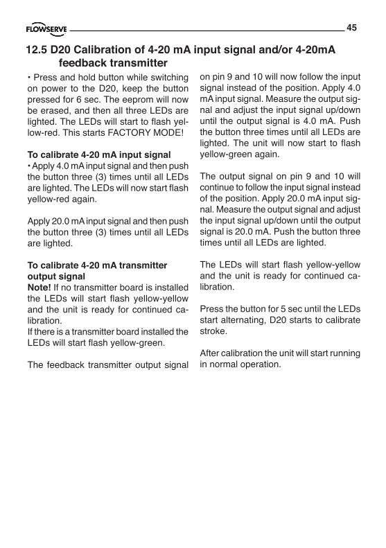
• Press and hold button while switching on power to the D20, keep the button pressed for 6 sec. The eeprom will now be erased, and then all three LEDs are lighted. The LEDs will start to flash yel-low-red. This starts FACTORY MODE!
To calibrate 4-20 mA input signal• Apply 4.0 mA input signal and then push the button three (3) times until all LEDs are lighted. The LEDs will now start flash yellow-red again.
Apply 20.0 mA input signal and then push the button three (3) times until all LEDs are lighted.
To calibrate 4-20 mA transmitter output signalNote! If no transmitter board is installed the LEDs will start flash yellow-yellow and the unit is ready for continued ca-libration.If there is a transmitter board installed the LEDs will start flash yellow-green.
The feedback transmitter output signal
on pin 9 and 10 will now follow the input signal instead of the position. Apply 4.0 mA input signal. Measure the output sig-nal and adjust the input signal up/down until the output signal is 4.0 mA. Push the button three times until all LEDs are lighted. The unit will now start to flash yellow-green again.
The output signal on pin 9 and 10 will continue to follow the input signal instead of the position. Apply 20.0 mA input sig-nal. Measure the output signal and adjust the input signal up/down until the output signal is 20.0 mA. Push the button three times until all LEDs are lighted.
The LEDs will start flash yellow-yellow and the unit is ready for continued ca-libration.
Press the button for 5 sec until the LEDs start alternating, D20 starts to calibrate stroke.
After calibration the unit will start running in normal operation.
12.5 D20 Calibration of 4-20 mA input signal and/or 4-20mA feedback transmitter

46
13. Trouble shooting
13.1 PMV D20 Normal operation
13.2 PMV D20 error codesAn unsuccessful calibration is indicated by the LED:s. The type of error is shown by the flash sequence.
R G
Error code Probable Cause Action
R Y G
(No movement)
Deviation between set valueand valve position.
No air supply orshaft do not move.
Pot not calibrated.
Hallsensor value too low.
Hallsensor span too low.
Hallsensor value too high.
Unit in Factory Mode.
4 - 20 mA feedback installed
R G R
R R G
R Y R
Check air supplyCheck shaft movement.
Calibrate the pot.
Check hallsensorconnection.
Calibrate 4 - 20 mAinput signal.
Calibrate output.
R
(Alarm)
Y R
Y G
Calibration
G
Y
Normal operation.
Valve fully closed or open”Cut off” enabled.
47
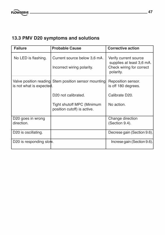
13.3 PMV D20 symptoms and solutions
Failure Probable Cause Corrective action
No LED is flashing. Current source below 3,6 mA . Verify current source supplies at least 3,6 mA. Incorrect wiring polarity. Check wiring for correct polarity. Valve position reading Stem position sensor mounting Reposition sensor. is not what is expected. is off 180 degrees. D20 not calibrated. Calibrate D20. Tight shutoff MPC (Minimum No action. position cutoff) is active.
D20 goes in wrong Change direction direction. (Section 9.4).
D20 is oscillating. Decrese gain (Section 9.6).
D20 is responding slow. Increse gain (Section 9.6).

48
14. Maintenance/service
14.1 Disassembling PMV D20
• Unscrew the three screws and remove the outer cover. When mounting cover – see page 14.
• Unscrew the four screws A and remove the inner cover.
• Unscrew the screws B, And remove the air relay assy.
When carrying out service, replacing a circuit board, etc., it may be necessary to remove and refit various parts of the positioner. This is described on the fol-lowing pages.
Read the Safety Instructions on page 3 before starting work on the positioner.
Cleanliness is essential when working with the positioner. Contamination in the air ducts will infallible lead to operational disturbances. Do not disassemble the unit more than that described here.
Do not take the valve block apart because its function will be impaired.
When working with the PMV D20 positioner, the work place must be equipped with ESD protection before the work is started.
Always turn off the air and electrical supplies before starting any work.
When upgrading electronically parts inside a PMV positioner approved for installation in Hazardous locations special procedures apply, permission from PMV/Flowserve is required prior to the start of work.
Please contact a Flowserve office for information regarding proper procedures. www.pmv.nu or [email protected]
A
B

49
14.2 Disassembling PMV D20 Ex
Removing cover and inner cover• Unscrew the screw A and remove the cover. When mounting cover – see page 14.
• Unscrew the three screws B, lift the circuit board.
• Loosen the cables C and D.
• Unscrew th two screws E and F and remove the air relay assy.
B A
C D
E F

50
1211
16
15 1918
17 1
21
2
14 3
5
8 7
9
4
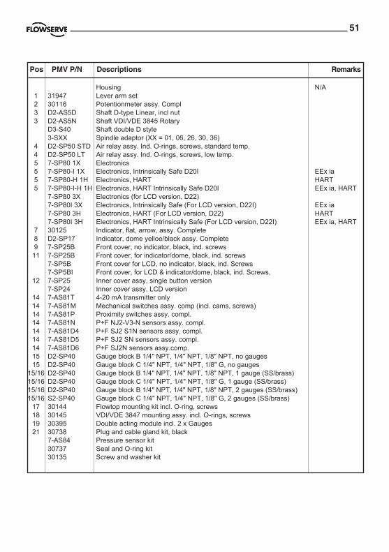
15. Spare parts
51
Pos PMV P/N Descriptions Remarks
Housing N/A1 31947 Lever arm set2 30116 Potentionmeter assy. Compl3 D2-AS5D Shaft D-type Linear, incl nut3 D2-AS5N Shaft VDI/VDE 3845 Rotary
D3-S40 Shaft double D style3-SXX Spindle adaptor (XX = 01, 06, 26, 30, 36)
4 D2-SP50 STD Air relay assy. Ind. O-rings, screws, standard temp.4 D2-SP50 LT Air relay assy. Ind. O-rings, screws, low temp.5 7-SP80 1X Electronics5 7-SP80-I 1X Electronics, Intrinsically Safe D20I EEx ia5 7-SP80-H 1H Electronics, HART HART5 7-SP80-I-H 1H Electronics, HART Intrinsically Safe D20I EEx ia, HART
7-SP80 3X Electronics (for LCD version, D22)7-SP80I 3X Electronics, Intrinsically Safe (For LCD version, D22I) EEx ia7-SP80 3H Electronics, HART (For LCD version, D22) HART7-SP80I 3H Electronics, HART Intrinsically Safe (For LCD version, D22I) EEx ia, HART
7 30125 Indicator, flat, arrow, assy. Complete8 D2-SP17 Indicator, dome yelloe/black assy. Complete9 7-SP25B Front cover, no indicator, black, ind. screws11 7-SP25B Front cover, for indicator/dome, black, ind. screws
7-SP5B Front cover for LCD, no indicator, black, ind. Screws7-SP5BI Front cover, for LCD & indicator/dome, black, ind. Screws,
12 7-SP25 Inner cover assy, single button version7-SP24 Inner cover assy, LCD version
14 7-AS81T 4-20 mA transmitter only14 7-AS81M Mechanical switches assy. comp (incl. cams, screws)14 7-AS81P Proximity switches assy. compl.14 7-AS81N P+F NJ2-V3-N sensors assy. compl.14 7-AS81D4 P+F SJ2 S1N sensors assy. compl.14 7-AS81D5 P+F SJ2 SN sensors assy. compl.14 7-AS81D6 P+F SJ2N sensors assy.comp.15 D2-SP40 Gauge block B 1/4" NPT, 1/4" NPT, 1/8" NPT, no gauges15 D2-SP40 Gauge block C 1/4" NPT, 1/4" NPT, 1/8" G, no gauges
15/16 D2-SP40 Gauge block B 1/4" NPT, 1/4" NPT, 1/8" NPT, 1 gauge (SS/brass)15/16 D2-SP40 Gauge block C 1/4" NPT, 1/4" NPT, 1/8" G, 1 gauge (SS/brass)15/16 D2-SP40 Gauge block B 1/4" NPT, 1/4" NPT, 1/8" NPT, 2 gauges (SS/brass)15/16 S2-SP40 Gauge block C 1/4" NPT, 1/4" NPT, 1/8" G, 2 gauges (SS/brass)
17 30144 Flowtop mounting kit incl. O-ring, screws18 30145 VDI/VDE 3847 mounting assy. incl. O-rings, screws19 30395 Double acting module incl. 2 x Gauges21 30738 Plug and cable gland kit, black
7-AS84 Pressure sensor kit30737 Seal and O-ring kit30135 Screw and washer kit
For Explosion proof version of D20 & D22 Housing N/A
1 Cover, large N/A2 O-ring large N/A3 D3E-SP4 Inner cover assy for LCD version4 3-SP37HR LCD Display for D225 3E-SP851X Electronics D20, single button version D20
Pos PMV P/N Descriptions Remarks

52

53
Pos PMV P/N Descriptions Remarks
Housing N/A1 31947 Lever arm set2 30116 Potentionmeter assy. Compl3 D2-AS5D Shaft D-type Linear, incl nut3 D2-AS5N Shaft VDI/VDE 3845 Rotary
D3-S40 Shaft double D style3-SXX Spindle adaptor (XX = 01, 06, 26, 30, 36)
4 D2-SP50 STD Air relay assy. Ind. O-rings, screws, standard temp.4 D2-SP50 LT Air relay assy. Ind. O-rings, screws, low temp.5 7-SP80 1X Electronics5 7-SP80-I 1X Electronics, Intrinsically Safe D20I EEx ia5 7-SP80-H 1H Electronics, HART HART5 7-SP80-I-H 1H Electronics, HART Intrinsically Safe D20I EEx ia, HART
7-SP80 3X Electronics (for LCD version, D22)7-SP80I 3X Electronics, Intrinsically Safe (For LCD version, D22I) EEx ia7-SP80 3H Electronics, HART (For LCD version, D22) HART7-SP80I 3H Electronics, HART Intrinsically Safe (For LCD version, D22I) EEx ia, HART
7 30125 Indicator, flat, arrow, assy. Complete8 D2-SP17 Indicator, dome yelloe/black assy. Complete9 7-SP25B Front cover, no indicator, black, ind. screws11 7-SP25B Front cover, for indicator/dome, black, ind. screws
7-SP5B Front cover for LCD, no indicator, black, ind. Screws7-SP5BI Front cover, for LCD & indicator/dome, black, ind. Screws,
12 7-SP25 Inner cover assy, single button version7-SP24 Inner cover assy, LCD version
14 7-AS81T 4-20 mA transmitter only14 7-AS81M Mechanical switches assy. comp (incl. cams, screws)14 7-AS81P Proximity switches assy. compl.14 7-AS81N P+F NJ2-V3-N sensors assy. compl.14 7-AS81D4 P+F SJ2 S1N sensors assy. compl.14 7-AS81D5 P+F SJ2 SN sensors assy. compl.14 7-AS81D6 P+F SJ2N sensors assy.comp.15 D2-SP40 Gauge block B 1/4" NPT, 1/4" NPT, 1/8" NPT, no gauges15 D2-SP40 Gauge block C 1/4" NPT, 1/4" NPT, 1/8" G, no gauges
15/16 D2-SP40 Gauge block B 1/4" NPT, 1/4" NPT, 1/8" NPT, 1 gauge (SS/brass)15/16 D2-SP40 Gauge block C 1/4" NPT, 1/4" NPT, 1/8" G, 1 gauge (SS/brass)15/16 D2-SP40 Gauge block B 1/4" NPT, 1/4" NPT, 1/8" NPT, 2 gauges (SS/brass)15/16 S2-SP40 Gauge block C 1/4" NPT, 1/4" NPT, 1/8" G, 2 gauges (SS/brass)
17 30144 Flowtop mounting kit incl. O-ring, screws18 30145 VDI/VDE 3847 mounting assy. incl. O-rings, screws19 30395 Double acting module incl. 2 x Gauges21 30738 Plug and cable gland kit, black
7-AS84 Pressure sensor kit30737 Seal and O-ring kit30135 Screw and washer kit
For Explosion proof version of D20 & D22 Housing N/A
1 Cover, large N/A2 O-ring large N/A3 D3E-SP4 Inner cover assy for LCD version4 3-SP37HR LCD Display for D225 3E-SP851X Electronics D20, single button version D205 3E-SP851XT Electronics + 4-20mA transmitter, Single button version D205 3E-SP851H Electronics, HART, Single button version D20 HART5 3E-SP851HT Electronics, HART + 4-20mA transmitter, Single button version D20 HART5 3ESP85 3X Electronics, for LCD version D225 3ESP85 3XT Electronics + 4-20mA transmitter for LCD version D225 3ESP85 H Electronics, HART for LCD version D22 HART5 3ESP85 HT Electronics, HART + 4-20mA transmitter for LCD version D22 HART6 D3E-AS4 Potentiometer compl. incl. spring, holder, cable7 D2-SP50 STD Air relay assy. Ind. O-rings, screws, standard temp.7 D2-SP50 LT Air relay assy. Ind. O-rings, screws, low temp version8 7-AS84 Pressure sensor kit9 Cover, terminals N/A10 O-ring small N/A11 D20-AS99 Terminal PCB D20 Single button version11 3E-SP83 Terminal PCB D22 LCD / Menu version12 Spring, see spindle assy13 3-AS23 Shaft assy, D-type Linear, incl nut and spring13 3-AS39 Shaft assy, VDI/VDE 3845 Rotary and spring13 3-AS09 Shaft assy, double D style and spring
3-SXX Spindle adaptor (XX = 01, 06, 26, 30, 36)14 D3E-SP67 Bleeder cap15 O-ring kit Explosion proof
Pos PMV P/N Descriptions Remarks

FCD PMENIM0012-03 09/16
PMV Automation ABKorta Gatan 9SE-171 54 SOLNASWEDENPhone: +46 (0)8-555 106 00E-mail: [email protected]
PMV USA14219 Westfair West DriveHouston, TX 77041, USAPhone: +1 281 671 9209Fax: +1 281 671 9268E-mail: [email protected]
Flowserve Flow ControlBurrell Road, Haywards HeathWest Sussex RH16 1TLPhone: +44(0)1444 314400E-mail: [email protected]
Flowserve Flow Control BeneluxRechtzaad 174703 RC RoosendaalTHE NETHERLANDSPhone: +31 (0) 30 6771946Fax: +27 (0) 30 6772471E-mail: [email protected]
Flowserve Flow Control GmbHRudolf-Plank Strasse 2D-76275 EttlingenGERMANYPhone: +49 (0) 7243 103 0Fax: +49 (0) 7243 103 222E-mail: [email protected]
Flowserve S.p.a.Via Prealpi, 3020032 Cormano (Milano)ITALYPhone: +39 (0) 2 663 251Fax: +39 (0) 2 615 18 63E-mail: [email protected]
Flowserve CorporationNo. 35, Baiyu RoadSuzhou Industrial ParkSuzhou 215021, Jiangsu Province,PRCPhone: +86-512-6288-1688Fax: +86-512-6288-8737Flowserve (China)585, Hanwei Plaza7 Guanghau RoadBeijing, China 100004Phone: +86 10 6561 1900
Flowserve Pte LtdNo. 12 Tuas Avenue 20Singapore 638824Phone: +65 6879 8900Fax: +65 6862 4940
Flowserve do Brasil LtdaRua Tocantins, 128 - Bairro Nova GertiSão Caetano do Sul,São Paulo 09580-130 BrazilPhone: +5511 4231 6300Fax: +5511 4231 6329 - 423