pmv d3 digital positioner installation - flowserve the safety instructions in this manual carefully...
TRANSCRIPT

®
USER INSTRUCTIONSInstallation
Operation
MaintenanceFCD PMENIM0001-06 A5 - 09/16
PMV D3 Digital Positioner
2
Contents
1.Introduction .......................................................................................................... 3 Safety instruction ................................................................................................. 3
2. Storage ................................................................................................................ 5 General ................................................................................................................. 5 Storage indoors ................................................................................................... 5 Storage outdoors or for a longer period ............................................................... 5 Storage in a warm place ....................................................................................... 53. Design ..................................................................................... 64. Variants ................................................................................... 7
5. Function .............................................................................................................. 8
6. Installation .......................................................................................................... 9 Removal of covers ............................................................................................... 9 Tubing .................................................................................................................. 9 Air supply requirements ....................................................................................... 9 Mounting .............................................................................................................10 Connections .........................................................................................................11 Single action positioner, Direct function...............................................................12 Double action positioner, Direct function .............................................................12 Electrical connections ..........................................................................................13 Signs ....................................................................................................................15 D3 Digital Positioner model code .........................................................................16
7. Control ................................................................................................................17 Menus and pushbuttons ......................................................................................17 Other functions ....................................................................................................17 Menu indicator .....................................................................................................18 Menus ..................................................................................................................18 Changing parameter values ..................................................................................18 Menu system .......................................................................................................19 First start (with calibration sequence) ..................................................................20 ISA100 Wireless function (WL) ...........................................................................23 Expert Calibration .................................................................................................35
8. Maintenance/service ..........................................................................................37 Disassembling PMV D3 .......................................................................................37 Silencer ................................................................................................................39 Potentiometer ......................................................................................................40 Transmitter boards ...............................................................................................40 Disassembling PMV D3 Ex ...................................................................................43 Filter change ........................................................................................................44
9. Trouble shooting .................................................................................................45
10. Technical data ...................................................................................................46
11. Dimensions .......................................................................................................48
12. Spare parts .......................................................................................................51
PMV D3 Digital Positioner FCD PMENIM0001-04 - 02/15
3
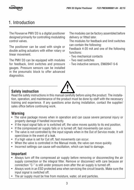
Safety instructionRead the safety instructions in this manual carefully before using the product. The installa-tion, operation, and maintenance of the product must be done by staff with the necessary training and experience. If any questions arise during installation, contact the supplier/sales office before continuing work.
Warning• The valve package moves when in operation and can cause severe personal injury or
property damage if handled incorrectly.• If the input signal fails or is switched off, the valve moves quickly to its end position.• If the compressed air supply fails or is turned off, fast movements can occur.• The valve is not controlled by the input signals when in the Out of Service mode. It will
open/close in the event of a leak.• If a high value is set for Cut off, fast movements can occur.• When the valve is controlled in the Manual mode, the valve can move quickly.• Incorrect settings can cause self-oscillation, which can lead to damage.
Important• Always turn off the compressed air supply before removing or disconnecting the air
supply connection or the integral filter. Remove or disconnect with care because air connection ”C-” is still under pressure even after the air supply is turned off.
• Always work in an ESD protected area when servicing the circuit boards. Make sure the input signal is switched off.
• The air supply must be free from moisture, water, oil and particles.
The Flowserve PMV D3 is a digital positioner designed primarily for controlling modulating control valves.
The positioner can be used with single or double acting actuators with either rotary or linear movement.
The PMV D3 can be equipped with modules for feedback, limit switches and pressure gauges. Pressure sensors can be installed in the pneumatic block to offer advanced diagnostics.
1. Introduction
The modules can be factory assembled before delivery or fitted later.The modules for feedback and limit switches can contain the following:Feedback 4-20 mA and one of the following functions:- Two mechanical contacts- Two reed switches- Two inductive sensors, EN60947-5-6
PMV D3 Digital Positioner FCD PMENIM0001-04 - 02/15
4
Special Conditions for Safe UseThe enclosure of PMV D3I (Intrinsically safe) is made of aluminum and any impact or friction caused by external objects should be avoided in the application.
Spare parts for certified products for hazardous locations
Flowserve will only supply spare parts for PMV Explosion Proof or Intrinsically Safe products to certified purchasers.In order to be allowed to purchase spare parts for IS and EX products the purchaser must be registered by a proper Notified Body and covered under PMV QAN.
According to IEC 60079-19 section 4 - 4.4.3.2 modifications to the positioner are not permitted.
If the equipment is modified the user shall be informed in writing that the equipment is no longer suitable for use in an explosive atmosphere.
Should you have any questions regarding the above, please feel free to contact us anytime.
PMV D3 Digital Positioner FCD PMENIM0001-04 - 02/15

5
2. Storage
GeneralThe PMV D3 positioner is a precision instrument. It is essential that it is handled and stored correctly. Always follow the instructions below!
Note: As soon as the positioner is connected and started, internal air leakage will provide protection against corrosion and prevent the ingress of moisture. For this reason, the air supply pressure should always be kept on.
Storage indoorsStore the positioner in its original packaging. The storage environment must be clean, dry, and cool (15 to 26°C, 59 to 79°F).
Storage outdoors or for a longer periodIf the positioner must be stored outdoors, it is important that all the cover screws are tightened and that all connections are properly sealed. The unit should be packed with a desiccant (silica gel) in a plastic bag or similar, covered with plastic, and not exposed to sunlight, rain, or snow.
This is also applicable for long-term storage (more than 1 month) and for transport by sea.
Storage in a warm placeWhen the positioner is stored in a warm place with a high relative humidity and is subjected to daily temperature variations, the air inside the unit will expand and contract.
This means that air from outside the unit may be drawn into the positioner. Depending on the temperature variations, relative humidity, and other factors, condensation and corrosion can occur inside the unit, which in turn can give rise to functional disorders or a failure.
PMV D3 Digital Positioner FCD PMENIM0001-06 A5 09/16
6
3. Design
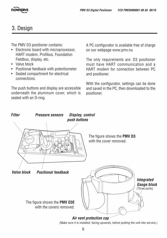
Filter Pressure sensors Display, control push buttons
Positional feedback Valve block
Air vent protection cap
Integrated Gauge block
The PMV D3 positioner contains:• Electronic board with microprocessor, HART modem, Profibus, Foundation Fieldbus, display, etc.• Valve block• Positional feedback with potentiometer• Sealed compartment for electrical connections.
The push buttons and display are accessible underneath the aluminum cover, which is sealed with an O-ring.
The figure shows the PMV D3 with the cover removed.
(Make sure it is installed, facing upwards, before putting the unit into service.)
(Three ports)
The figure shows the PMV D3E with the covers removed.
A PC configurator is available free of charge on our webpage www.pmv.nu
The only requirements are: D3 positioner must have HART communication and a HART modem for connection between PC and positioner.
With the configurator, settings can be done and saved in the PC, then downloaded to the positioner.
PMV D3 Digital Positioner FCD PMENIM0001-06 A5 09/16

7
Integrated Gauge block
The figure shows the PMV D3 with the cover removed.
4. Variants
PMV D3 General purposeThe PMV D3 digital positioner has an easy to use user interface with 5 pushbuttons and local graphic LCD display. Communication options include 4-20mA HART, Foundation Fieldbus and Profibus PA. All PMV D3 posi-tioners are available with Feedback, Fail Freeze (Fail in last position and hold when power is lost), 270-degree rotation (for extended travel) and gauge block.
PMV D3 Intrinsically safeThe PMV D3 digital positioner is available in intrinsically safe version for installation in hazardous areas. The intrinsically safe PMV D3 has all the same features and options as the general purpose version, gauge block, local graphic LCD display and feedback option etc. Communication with Hart, Profibus and Foundation Fieldbus is possible.
ATEX: II 1G Ex ia IIC T4 Ga Ta:80 ˚C / IP66
Pressure sensorsPressure sensors can be installed in the pneumatic block in order to provide advanced diagnostics in combination with ValveSight software.
PMV D3 Explosion proofThe PMV D3 digital positioner is available in explosion proof enclosure. The explosion proof PMV D3 features the same easy to use interface for local configuration as the general purpose version. Communication with Hart, Foundation Fieldbus and Profibus is possible.Further features are gauge ports and local graphic LCD display.
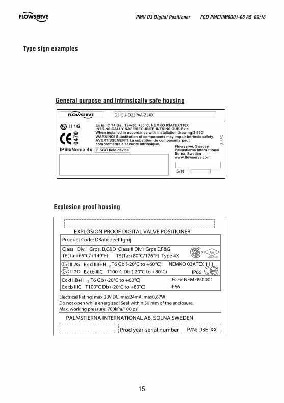
ATEX: II 2G Ex d IIB+H2 T6 Gb (-20°C to +60 °C) II 2D Ex tb IIIC T100°C Db (-20°C to +80°C)CSA, FM: Class I, Div.1 Grps B, C, DClass II, Div.1 Grps E, F, GClass III, Div.1T6, T5 / Type 4X
PMV D3 Digital Positioner FCD PMENIM0001-06 A5 09/16
8
5. Function
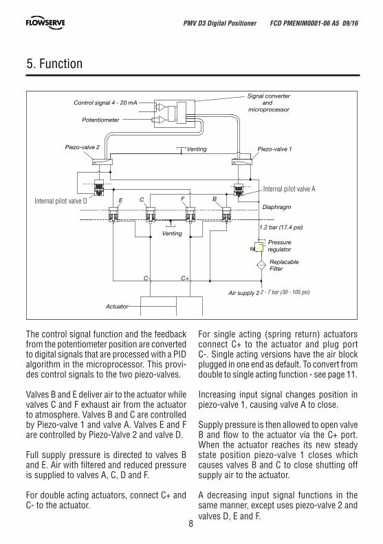
The control signal function and the feedback from the potentiometer position are converted to digital signals that are processed with a PID algorithm in the microprocessor. This provi-des control signals to the two piezo-valves.
Valves B and E deliver air to the actuator while valves C and F exhaust air from the actuator to atmosphere. Valves B and C are controlled by Piezo-valve 1 and valve A. Valves E and F are controlled by Piezo-Valve 2 and valve D.
Full supply pressure is directed to valves B and E. Air with filtered and reduced pressure is supplied to valves A, C, D and F.
For double acting actuators, connect C+ and C- to the actuator.
C-
Venting
Air supply 2 - 6 bar (29-87 psi)
Pressureregulator
Piezo-valve 1Piezo-valve 2
Control signal 4 - 20 mA
Potentiometer
D E C F B
A
1.2 bar (17.4 psi)
ReplacableFilter
Actuator
Diaphragm
C+
Venting
Signal converterand
microprocessor
For single acting (spring return) actuators connect C+ to the actuator and plug port C-. Single acting versions have the air block plugged in one end as default. To convert from double to single acting function - see page 11.
Increasing input signal changes position in piezo-valve 1, causing valve A to close.
Supply pressure is then allowed to open valve B and flow to the actuator via the C+ port. When the actuator reaches its new steady state position piezo-valve 1 closes which causes valves B and C to close shutting off supply air to the actuator.
A decreasing input signal functions in the same manner, except uses piezo-valve 2 and valves D, E and F.
2 - 7 bar (30 - 105 psi)
Internal pilot valve A
Internal pilot valve D
PMV D3 Digital Positioner FCD PMENIM0001-06 A5 09/16
9
TubingUse tubes with a minimum inner diameter of Ø 6 mm (1/4”).
Air supply requirements
Poor quality in air supply is the main cause of problems in pneumatic systems.
The air supply must be free from moisture, water, oil and particles and delivered @ 2-7 bar (30-105 psi)Standard: DIN/ISO 8573-1-2001 3.2.3Filtered to 5 Micron, dew point -40°C/FOil 1mg/m³ (0,83 ppm by weight)
The air must come from a refrigeration dried supply or be treated in such a way that its dew point is at least 10°C (18°F) below the lowest expected ambient temperature.
To ensure a stable and problem-free air supply, we recommend the installation of a filter/pressure regulator <5µ as close to the positioner as possible.
Before the air supply is connected to thepositioner, we recommend the hose is opened freely for 2 to 3 minutes to allow any conta-mination to be blown out. Direct the air jet into a large paper bag to trap any water, oil, or other foreign materials. If this indicates that the air system is contaminated, it should be properly cleaned.
WARNING! Do not direct the open air jet towards people or objects because it may cause personal injury or damage.
6. Installation
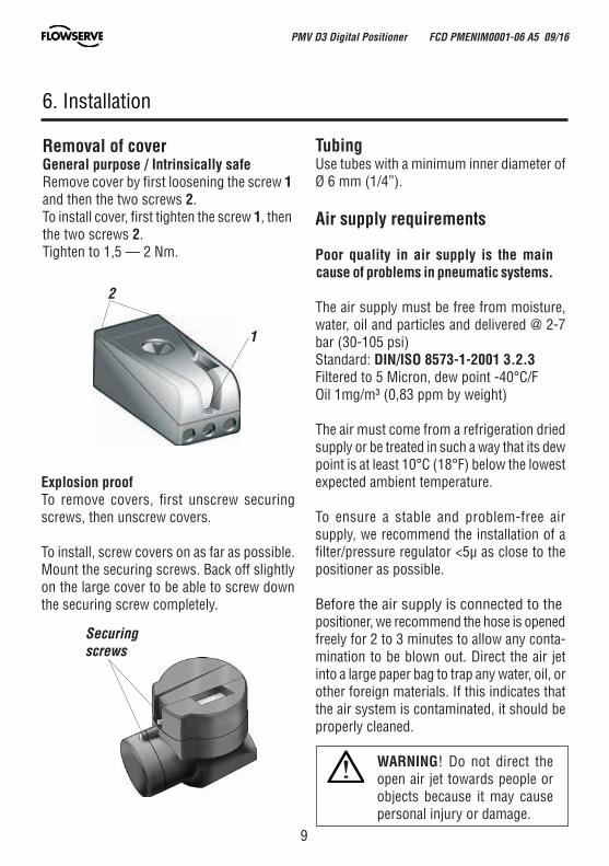
Removal of coverGeneral purpose / Intrinsically safeRemove cover by first loosening the screw 1 and then the two screws 2.To install cover, first tighten the screw 1, then the two screws 2.Tighten to 1,5 — 2 Nm.
2
1
Explosion proofTo remove covers, first unscrew securing screws, then unscrew covers.
To install, screw covers on as far as possible. Mount the securing screws. Back off slightly on the large cover to be able to screw down the securing screw completely.
Securing screws
PMV D3 Digital Positioner FCD PMENIM0001-06 A5 09/16
10
Mounting
Note: If the positioner is installed in a hazardous environment, it must be of a type approved for this purpose.
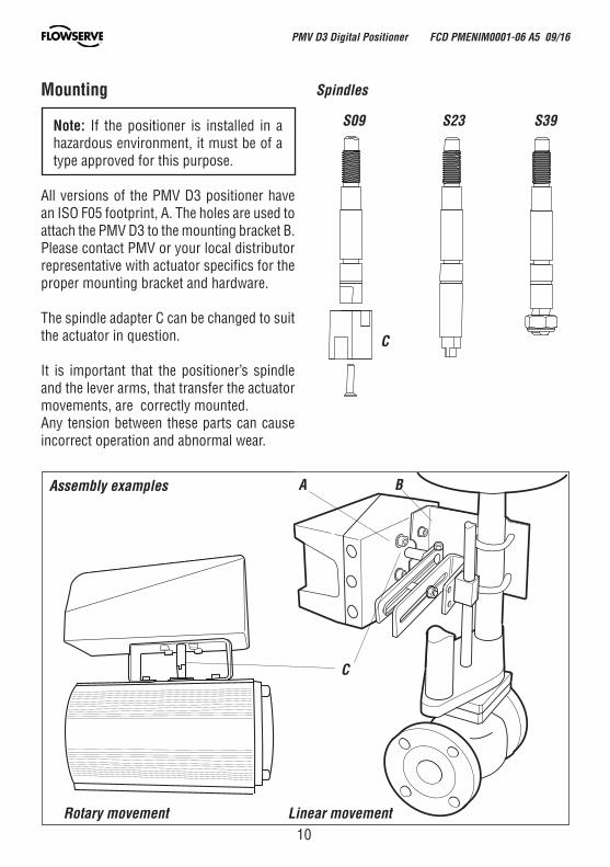
All versions of the PMV D3 positioner have an ISO F05 footprint, A. The holes are used to attach the PMV D3 to the mounting bracket B. Please contact PMV or your local distributor representative with actuator specifics for the proper mounting bracket and hardware.
The spindle adapter C can be changed to suit the actuator in question.
It is important that the positioner’s spindle and the lever arms, that transfer the actuator movements, are correctly mounted. Any tension between these parts can cause incorrect operation and abnormal wear.
Assembly examples A B
C
C
Rotary movement Linear movement
Spindles
S09 S23 S39
PMV D3 Digital Positioner FCD PMENIM0001-06 A5 09/16
11C– S C+
C– S C+
For data for air and electrical connections, see section Technical Data on page 46.
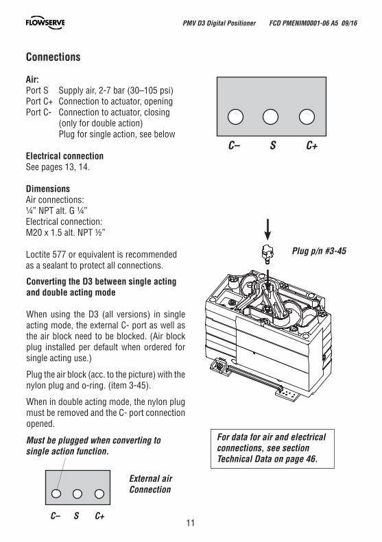
Connections
Air:Port S Supply air, 2-7 bar (30–105 psi) Port C+ Connection to actuator, openingPort C- Connection to actuator, closing (only for double action) Plug for single action, see below
Electrical connectionSee pages 13, 14.
DimensionsAir connections: ¼” NPT alt. G ¼”Electrical connection: M20 x 1.5 alt. NPT ½”
Loctite 577 or equivalent is recommended as a sealant to protect all connections.
Converting the D3 between single acting and double acting mode
When using the D3 (all versions) in single acting mode, the external C- port as well as the air block need to be blocked. (Air block plug installed per default when ordered for single acting use.)
Plug the air block (acc. to the picture) with the nylon plug and o-ring. (item 3-45).
When in double acting mode, the nylon plug must be removed and the C- port connection opened.
Must be plugged when converting to single action function.
External air Connection
Plug p/n #3-45
PMV D3 Digital Positioner FCD PMENIM0001-06 A5 09/16
12
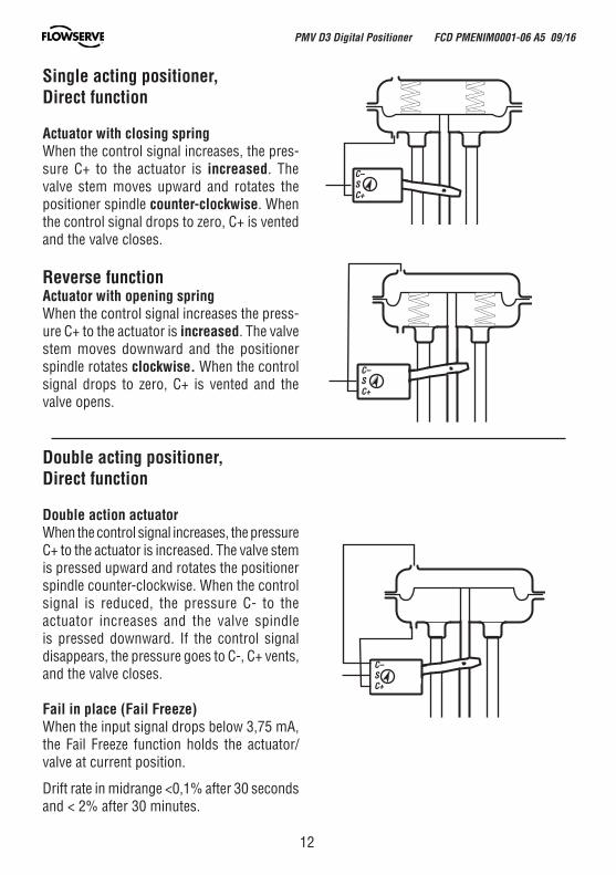
Single acting positioner,Direct function
Actuator with closing springWhen the control signal increases, the pres-sure C+ to the actuator is increased. The valve stem moves upward and rotates the positioner spindle counter-clockwise. When the control signal drops to zero, C+ is vented and the valve closes.
Reverse functionActuator with opening springWhen the control signal increases the press-ure C+ to the actuator is increased. The valve stem moves downward and the positioner spindle rotates clockwise. When the control signal drops to zero, C+ is vented and the valve opens.
Double acting positioner,Direct function
Double action actuatorWhen the control signal increases, the pressure C+ to the actuator is increased. The valve stem is pressed upward and rotates the positioner spindle counter-clockwise. When the control signal is reduced, the pressure C- to the actuator increases and the valve spindle is pressed downward. If the control signal disappears, the pressure goes to C-, C+ vents, and the valve closes.
Fail in place (Fail Freeze)When the input signal drops below 3,75 mA, the Fail Freeze function holds the actuator/valve at current position.
Drift rate in midrange <0,1% after 30 seconds and < 2% after 30 minutes.
C–SC+
C–SC+
C–SC+
PMV D3 Digital Positioner FCD PMENIM0001-06 A5 09/16
13
Warning! In a hazardous environment where there is a risk of explosion, electrical connections must comply with the relevant regulations.
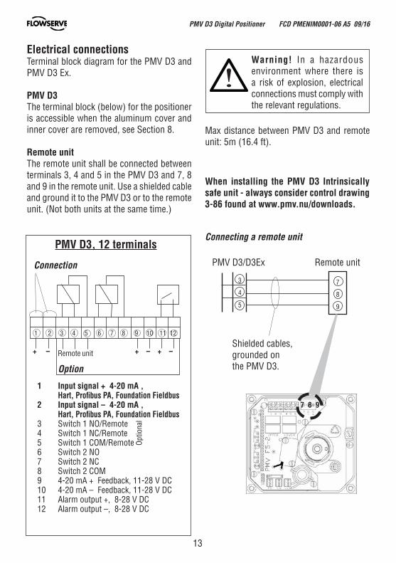
Electrical connectionsTerminal block diagram for the PMV D3 and PMV D3 Ex.
PMV D3The terminal block (below) for the positioner is accessible when the aluminum cover and inner cover are removed, see Section 8.
Remote unitThe remote unit shall be connected between terminals 3, 4 and 5 in the PMV D3 and 7, 8 and 9 in the remote unit. Use a shielded cable and ground it to the PMV D3 or to the remote unit. (Not both units at the same time.)
Max distance between PMV D3 and remote unit: 5m (16.4 ft).
When installing the PMV D3 Intrinsically safe unit - always consider control drawing 3-86 found at www.pmv.nu/downloads.
1 Input signal + 4-20 mA , Hart, Profibus PA, Foundation Fieldbus2 Input signal – 4-20 mA , Hart, Profibus PA, Foundation Fieldbus3 Switch 1 NO/Remote4 Switch 1 NC/Remote5 Switch 1 COM/Remote6 Switch 2 NO7 Switch 2 NC8 Switch 2 COM9 4-20 mA + Feedback, 11-28 V DC10 4-20 mA – Feedback, 11-28 V DC11 Alarm output +, 8-28 V DC12 Alarm output –, 8-28 V DC
PMV D3, 12 terminals
Option
Connection
Connecting a remote unit
+ – + – + – Remote unit
1 2 3 4 5 6 7 8 9 10 11 12
Opt
iona
l
PMV D3/D3Ex Remote unit
3
4
5
7
8
9
Shielded cables, grounded on the PMV D3.
7 8 9
PMV D3 Digital Positioner FCD PMENIM0001-06 A5 09/16
14
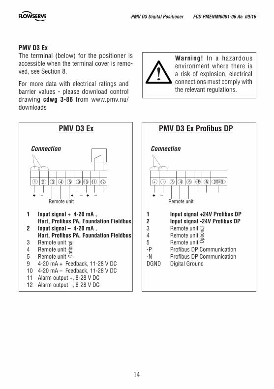
PMV D3 ExThe terminal (below) for the positioner is accessible when the terminal cover is remo-ved, see Section 8.
Warning! In a hazardous environment where there is a risk of explosion, electrical connections must comply with the relevant regulations.
For more data with electrical ratings and barrier values - please download control drawing cdwg 3-86 from www.pmv.nu/downloads
1 Input signal + 4-20 mA , Hart, Profibus PA, Foundation Fieldbus2 Input signal – 4-20 mA , Hart, Profibus PA, Foundation Fieldbus3 Remote unit4 Remote unit5 Remote unit9 4-20 mA + Feedback, 11-28 V DC10 4-20 mA – Feedback, 11-28 V DC11 Alarm output +, 8-28 V DC12 Alarm output –, 8-28 V DC
1 Input signal +24V Profibus DP2 Input signal -24V Profibus DP3 Remote unit4 Remote unit5 Remote unit-P Profibus DP Communication-N Profibus DP CommunicationDGND Digital Ground
Opt
iona
l Opt
iona
l
PMV D3 Ex PMV D3 Ex Profibus DP
Connection Connection
+ – + – + – + –
1 2 3 4 5 9 10 11 12 + - 3 4 5 -P -N DGND
Remote unit Remote unit
PMV D3 Digital Positioner FCD PMENIM0001-06 A5 09/16
15
General purpose and Intrinsically safe housing
Explosion proof housing
Type sign examples
compromettre a securite intrinsique.FISCO field device
0470
S/N
AVERTISSEMENT! La substition de composants peut
II 1G
WARNING! Substitution of components may impair intrinsic safety.
IP66/Nema 4x
3-88
C
When installed in accordance with installation drawing:3-86C
Ex ia IIC T4 Ga , Ta=-30..+80 C, NEMKO 03ATEX110XINTRINSICALLY SAFE/SECURITE INTRINSIQUE-Exia
Flowserve, SwedenPalmstierna InternationalSolna, Swedenwww.flowserve.com
D3IGU-D23PVA-Z5XX
PMV D3 Digital Positioner FCD PMENIM0001-06 A5 09/16
16
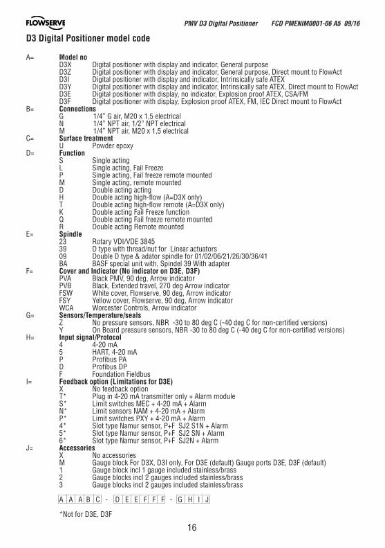
D3 Digital Positioner model code A= Model no D3X Digital positioner with display and indicator, General purpose D3Z Digital positioner with display and indicator, General purpose, Direct mount to FlowAct
D3I Digital positioner with display and indicator, Intrinsically safe ATEX D3Y Digital positioner with display and indicator, Intrinsically safe ATEX, Direct mount to FlowAct
D3E Digital positioner with display, no indicator, Explosion proof ATEX, CSA/FM D3F Digital positioner with display, Explosion proof ATEX, FM, IEC Direct mount to FlowAct
B= Connections G 1/4” G air, M20 x 1,5 electrical N 1/4” NPT air, 1/2” NPT electrical M 1/4” NPT air, M20 x 1,5 electrical C= Surface treatment U Powder epoxy D= Function S Single acting L Single acting, Fail Freeze P Single acting, Fail freeze remote mounted M Single acting, remote mounted D Double acting acting H Double acting high-flow (A=D3X only) T Double acting high-flow remote (A=D3X only) K Double acting Fail Freeze function Q Double acting Fail freeze remote mounted R Double acting Remote mounted E= Spindle 23 Rotary VDI/VDE 3845 39 D type with thread/nut for Linear actuators 09 Double D type & adator spindle for 01/02/06/21/26/30/36/41 BA BASF special unit with, Spindel 39 With adapterF= Cover and Indicator (No indicator on D3E, D3F) PVA Black PMV, 90 deg, Arrow indicator PVB Black, Extended travel, 270 deg Arrow indicator FSW White cover, Flowserve, 90 deg, Arrow indicator FSY Yellow cover, Flowserve, 90 deg, Arrow indicator WCA Worcester Controls, Arrow indicator G= Sensors/Temperature/seals Z No pressure sensors, NBR -30 to 80 deg C (-40 deg C for non-certified versions) Y On Board pressure sensors, NBR -30 to 80 deg C (-40 deg C for non-certified versions)H= Input signal/Protocol 4 4-20 mA 5 HART, 4-20 mA P Profibus PA D Profibus DP F Foundation Fieldbus I= Feedback option (Limitations for D3E) X No feedback option T* Plug in 4-20 mA transmitter only + Alarm module S* Limit switches MEC + 4-20 mA + Alarm N* Limit sensors NAM + 4-20 mA + Alarm P* Limit switches PXY + 4-20 mA + Alarm 4* Slot type Namur sensor, P+F SJ2 S1N + Alarm 5* Slot type Namur sensor, P+F SJ2 SN + Alarm 6* Slot type Namur sensor, P+F SJ2N + Alarm J= Accessories X No accessories M Gauge block For D3X, D3I only, For D3E (default) Gauge ports D3E, D3F (default) 1 Gauge block incl 1 gauge included stainless/brass 2 Gauge blocks incl 2 gauges included stainless/brass 3 Gauge blocks incl 2 gauges included stainless/brass A A A B C - D E E F F F - G H I J
*Not for D3E, D3F
PMV D3 Digital Positioner FCD PMENIM0001-06 A5 09/16
17
7. Control
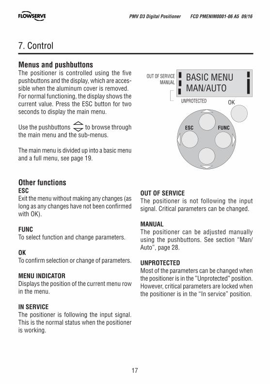
Menus and pushbuttonsThe positioner is controlled using the five pushbuttons and the display, which are acces-sible when the aluminum cover is removed.For normal functioning, the display shows the current value. Press the ESC button for two seconds to display the main menu.
Use the pushbuttons to browse through the main menu and the sub-menus.
The main menu is divided up into a basic menu and a full menu, see page 19.
Other functionsESCExit the menu without making any changes (as long as any changes have not been confirmed with OK).
FUNCTo select function and change parameters.
OKTo confirm selection or change of parameters.
MENU INDICATORDisplays the position of the current menu row in the menu.
IN SERVICEThe positioner is following the input signal. This is the normal status when the positioner is working.
ESC FUNC
OK
BASIC MENUMAN/AUTO
OUT OF SERVICE MANUAL
UNPROTECTED
OUT OF SERVICEThe positioner is not following the input signal. Critical parameters can be changed.
MANUALThe positioner can be adjusted manually using the pushbuttons. See section “Man/Auto”, page 28.
UNPROTECTEDMost of the parameters can be changed when the positioner is in the ”Unprotected” position. However, critical parameters are locked when the positioner is in the “In service” position.
PMV D3 Digital Positioner FCD PMENIM0001-06 A5 09/16
18
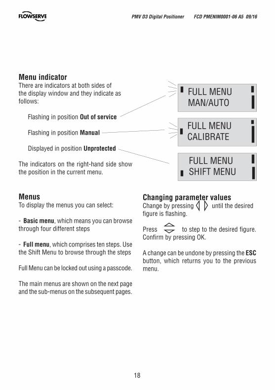
Menu indicatorThere are indicators at both sides of the display window and they indicate as follows:
Flashing in position Out of service
Flashing in position Manual
Displayed in position Unprotected
The indicators on the right-hand side show the position in the current menu.
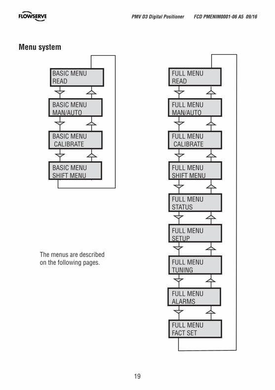
MenusTo display the menus you can select:
- Basic menu, which means you can browse through four different steps
- Full menu, which comprises ten steps. Use the Shift Menu to browse through the steps
Full Menu can be locked out using a passcode.
The main menus are shown on the next page and the sub-menus on the subsequent pages.
FULL MENUCALIBRATE
FULL MENUMAN/AUTO
FULL MENUSHIFT MENU
Changing parameter valuesChange by pressing until the desired figure is flashing.
Press to step to the desired figure. Confirm by pressing OK.
A change can be undone by pressing the ESC button, which returns you to the previous menu.
PMV D3 Digital Positioner FCD PMENIM0001-06 A5 09/16
19
BASIC MENUREAD
BASIC MENUMAN/AUTO
BASIC MENU CALIBRATE
BASIC MENUSHIFT MENU
FULL MENUREAD
FULL MENUMAN/AUTO
FULL MENU CALIBRATE
FULL MENUSHIFT MENU
FULL MENUSTATUS
FULL MENU SETUP
FULL MENUTUNING
FULL MENUALARMS
FULL MENUFACT SET
Menu system
The menus are described on the following pages.
PMV D3 Digital Positioner FCD PMENIM0001-06 A5 09/16

20
BASIC MENUCALIBRATE
First start“Calibrate” is displayed in the basic menu automatically, the first time power is applied. It can be selected from the basic/main menu at any time.
A complete auto-calibration takes up to 30 minutes depending on size of actuator and includes end limit calibration, auto-tuning, leak test and a check of the movement speed. Start the automatic calibration by selecting Auto-Cal and then answer the questions in the display by pressing OK or the respective arrow. The menu is described on page 24.
Calibration error messagesIf a fault occurs during calibration, one of the following error messages can be displayed:
No movement/press ESC to abortTypically the result of an air delivery issue to the actuator, or incorrect mounting and/or linkage arrangement. Check for proper supply air to the positioner, pinched tubing, proper actuator sizing, proper linkage and mounting arrangement.
Pot uncalibrated/press ESC to abortThe potentiometer has been set to an illegal value. The potentiomenter is aligned using the Calibrate - Expert cal - pot Menu. The calibration sequence must be restarted after the fault is corrected.
Air leak detected/ESC = abortOK = go onAn air leak has been detected. The calibration sequence should be restarted after the fault is corrected.
First start, Profibus PA/DPFor Profibus PA, connect the input signal at pos 1 and 2 on the terminal block. For Profibus DP, connect power to pos 1(+) and 2(-) and communication to pos 6 and 7. See Electrical connections on Page 13.
In the SETUP/Devicedata/Profibus: change the address from 126 to any number between 1-125.
Never use the same number with more than one unit. Install values in failsafe mode, for communication when there is loss of signal.Calibrate the unit.GSD files are available at our web-page www.pmv.nu
To install the D3_PROFIBUS.DDL file to Siemens SIMATIC PDM.1. Move the files to the directory where the DeviceInstall.exe is located.2. Run DeviceInstall.exe
For Expert Calibration parameters - see page 35
PMV D3 Digital Positioner FCD PMENIM0001-06 A5 09/16
21
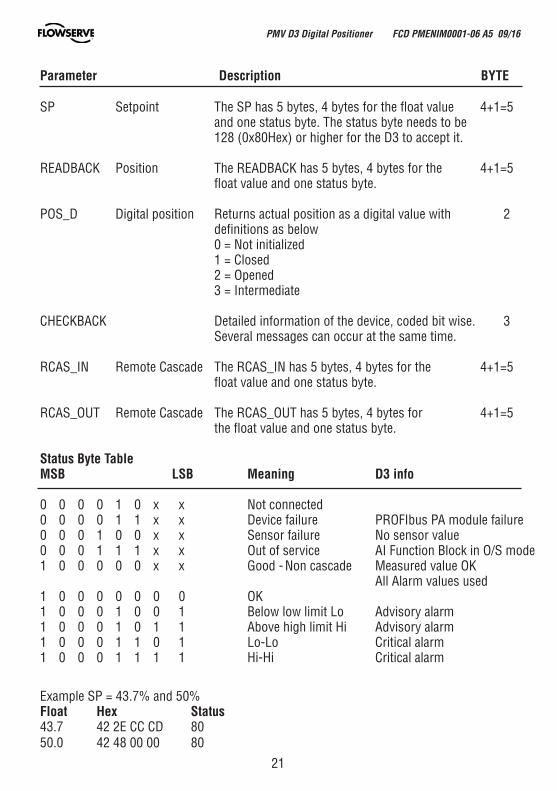
Parameter Description BYTE
SP Setpoint The SP has 5 bytes, 4 bytes for the float value 4+1=5 and one status byte. The status byte needs to be 128 (0x80Hex) or higher for the D3 to accept it.
READBACK Position The READBACK has 5 bytes, 4 bytes for the 4+1=5 float value and one status byte.
POS_D Digital position Returns actual position as a digital value with 2 definitions as below 0 = Not initialized 1 = Closed 2 = Opened 3 = Intermediate
CHECKBACK Detailed information of the device, coded bit wise. 3 Several messages can occur at the same time.
RCAS_IN Remote Cascade The RCAS_IN has 5 bytes, 4 bytes for the 4+1=5 float value and one status byte.
RCAS_OUT Remote Cascade The RCAS_OUT has 5 bytes, 4 bytes for 4+1=5 the float value and one status byte.
Status Byte TableMSB LSB Meaning D3 info
0 0 0 0 1 0 x x Not connected 0 0 0 0 1 1 x x Device failure PROFIbus PA module failure0 0 0 1 0 0 x x Sensor failure No sensor value0 0 0 1 1 1 x x Out of service AI Function Block in O/S mode1 0 0 0 0 0 x x Good - Non cascade Measured value OK All Alarm values used1 0 0 0 0 0 0 0 OK 1 0 0 0 1 0 0 1 Below low limit Lo Advisory alarm1 0 0 0 1 0 1 1 Above high limit Hi Advisory alarm1 0 0 0 1 1 0 1 Lo-Lo Critical alarm1 0 0 0 1 1 1 1 Hi-Hi Critical alarm
Example SP = 43.7% and 50%Float Hex Status 43.7 42 2E CC CD 8050.0 42 48 00 00 80
PMV D3 Digital Positioner FCD PMENIM0001-06 A5 09/16
22
(FF) Foundation Fieldbus function blocksFunction blocks are sets of data sorted by function and use. They can be connected to each other to solve a control process, or to a controlling DCS. To get a good introduction and understanding of FF look at www.fieldbus.org and download the “Technical Overview” from the About FF pages.
(TB) Transducer BlockThe TB contains unit specific data. Most of the parameters are the same as parameters found on the display. The data and the order of data varies between different products.The AO-block setpoint (SP) and process value (PV) parameters are transceived to the TB through a channel. The TB has to be in AUTO for the AO-block to be in AUTO.
The positioner has to be in menu-auto mode and in service to be controlled from the fieldbus.If the positioner is placed in menu-manual mode then the transducer block will be forced to (LO) local override. In this way an operator in the field will be able to control the positioner from the keypad, without affecting a control loop.
(RB) Resource BlockThe RB is a set of parameters that looks the same for all units and products. The values of the RB define unit information that concerns the Fieldbus Protocol such as MANUFAC_ID which informs the unique manufacturer id. For Flowserve it is 0x464C53.The RB has to be in AUTO for the AO-block to be in AUTO.
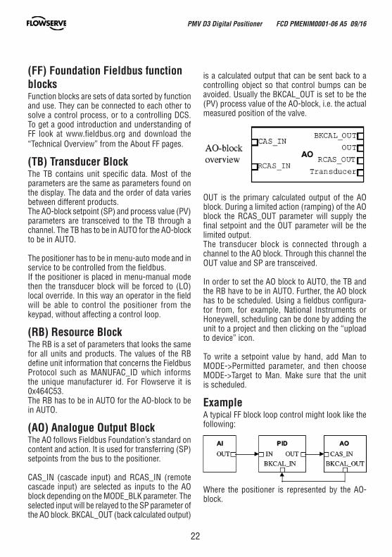
(AO) Analogue Output BlockThe AO follows Fieldbus Foundation’s standard on content and action. It is used for transferring (SP) setpoints from the bus to the positioner.
CAS_IN (cascade input) and RCAS_IN (remote cascade input) are selected as inputs to the AO block depending on the MODE_BLK parameter. The selected input will be relayed to the SP parameter of the AO block. BKCAL_OUT (back calculated output)
is a calculated output that can be sent back to a controlling object so that control bumps can be avoided. Usually the BKCAL_OUT is set to be the (PV) process value of the AO-block, i.e. the actual measured position of the valve.
OUT is the primary calculated output of the AO block. During a limited action (ramping) of the AO block the RCAS_OUT parameter will supply the final setpoint and the OUT parameter will be the limited output.The transducer block is connected through a channel to the AO block. Through this channel the OUT value and SP are transceived.
In order to set the AO block to AUTO, the TB and the RB have to be in AUTO. Further, the AO block has to be scheduled. Using a fieldbus configura-tor from, for example, National Instruments or Honeywell, scheduling can be done by adding the unit to a project and then clicking on the “upload to device” icon.
To write a setpoint value by hand, add Man to MODE->Permitted parameter, and then choose MODE->Target to Man. Make sure that the unit is scheduled.
ExampleA typical FF block loop control might look like the following:
Where the positioner is represented by the AO-block.
PMV D3 Digital Positioner FCD PMENIM0001-06 A5 09/16

23
PMV D3 Digital Positioner FCD PMENIM0001-06 A5 09/16
(WL) ISA100 Wireless function
The wireless D3 can be connected to an ISA100 wireless control system and perform regular control tasks. A normal update rate of the wireless AO block automatic control setpoint (OP) is 1 second. This setpoint is published to the device from the gateway. The variable to publish is configured in a wireless configurator tool. The readback value is also configured in this tool.
After configuring the wireless network and gateway, the D3 will join the network after a joining time. The D3 is then ready to start receiving the OP setpoint and do control work. The OP status is then Good Cascade and the AO block mode is Cascade/Auto.
In case the setpoint is lost for a time of the stale limit + FSTATE_TIME, the D3 will go into a safe state as defined by the FSTATE_OPT parameter.
D3 parameters can be viewed and set by a device management application that communicates with the gateway.
This application is DD-based. Before starting to get the D3 to join the network, the D3 has to be autocalibrated and provisioned for the network.
With a provisioning tool, the network number and device tag can be set.
To get the wireless D3 DD and recommendations for configuration tools, please contact PMV at:
Palmstierna International ABKorta gatan 9171 54 [email protected]
24
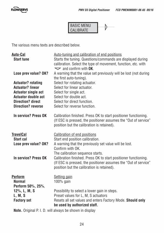
The various menu texts are described below.
Auto-Cal Auto-tuning and calibration of end positions Start tune Starts the tuning. Questions/commands are displayed during calibration. Select the type of movement, function, etc. with and confirm with OK. Lose prev value? OK? A warning that the value set previously will be lost (not during the first auto-tuning). Actuator? rotating Select for rotating actuator. Actuator? linear Select for linear actuator. Actuator single act Select for single act. Actuator double act Select for double act. Direction? direct Select for direct function. Direction? reverse Select for reverse function.
In service? Press OK Calibration finished. Press OK to start positioner functioning. (If ESC is pressed, the positioner assumes the “Out of service” position but the calibration is retained).
TravelCal Calibration of end positions Start cal Start end position calibration. Lose prev value? OK? A warning that the previously set value will be lost. Confirm with OK. The calibration sequence starts. In service? Press OK Calibration finished. Press OK to start positioner functioning. (If ESC is pressed, the positioner assumes the “Out of service” position but the calibration is retained).
Perform Setting gain Normal 100% gain Perform 50%, 25%, 12%, L, M, S Possibility to select a lower gain in steps. L, M, S Preset values for L, M, S actuators Factory set Resets all set values and enters Factory Mode. Should only be used by authorized staff. Note. Original P. I. D. will always be shown in display
BASIC MENUCALIBRATE
PMV D3 Digital Positioner FCD PMENIM0001-06 A5 09/16
25
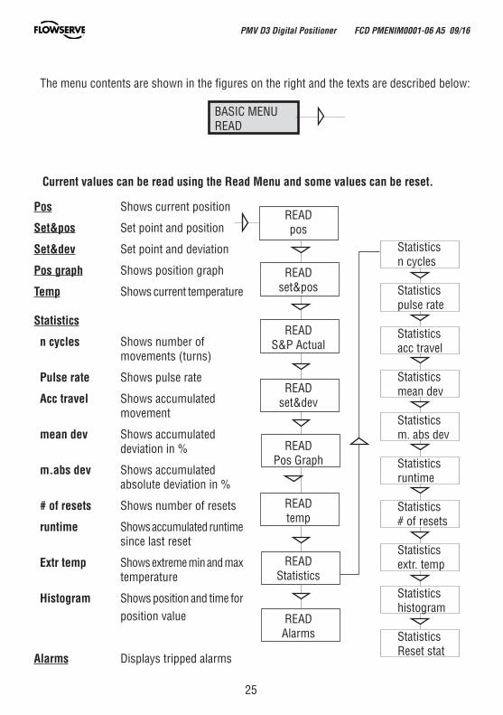
BASIC MENUREAD
Current values can be read using the Read Menu and some values can be reset.
Statisticsn cycles
Statisticspulse rate
Statisticsacc travel
Statisticsmean dev
Statisticsm. abs dev
Statisticsruntime
Statistics# of resets
Statisticsextr. temp
Statisticshistogram
StatisticsReset stat
Pos Shows current position
Set&pos Set point and position
Set&dev Set point and deviation
Pos graph Shows position graph
Temp Shows current temperature
Statistics
n cycles Shows number of movements (turns)
Pulse rate Shows pulse rate
Acc travel Shows accumulated movement
mean dev Shows accumulated deviation in %
m.abs dev Shows accumulated absolute deviation in %
# of resets Shows number of resets
runtime Shows accumulated runtime since last reset
Extr temp Shows extreme min and max temperature
Histogram Shows position and time for position value
Alarms Displays tripped alarms
The menu contents are shown in the figures on the right and the texts are described below:
READpos
READset&pos
READS&P Actual
READset&dev
READPos Graph
READtemp
READStatistics
READAlarms
PMV D3 Digital Positioner FCD PMENIM0001-06 A5 09/16
26
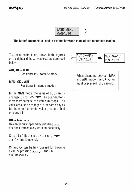
BASIC MENUMAN/AUTO
AUT, OK=MANPOS= 12,3% OK MAN, OK=AUT
POS= 12,3%
The menu contents are shown in the figures on the right and the various texts are described below:
AUT, OK = MAN Positioner in automatic mode
MAN, OK = AUT Positioner in manual mode
In the MAN mode, the value of POS can be changed using . The push-buttons increase/decrease the value in steps. The value can also be changed in the same way as for the other parameter values, as described on page 18
Other functionsC+ can be fully opened by pressing and then immediately OK simultaneously.
C- can be fully opened by pressing and OK simultaneously.
C+ and C- can be fully opened for blowing clean by pressing and OK simultaneously.
When changing between MAN and AUT mode, the OK button must be pressed for 3 seconds.
The Man/Auto menu is used to change between manual and automatic modes.
PMV D3 Digital Positioner FCD PMENIM0001-06 A5 09/16
27
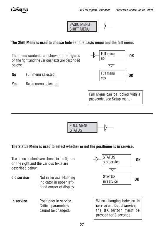
BASIC MENUSHIFT MENU
Full menuno
OK
Full menuyes
OK
The Shift Menu is used to choose between the basic menu and the full menu.
The menu contents are shown in the figures on the right and the various texts are described below:
No Full menu selected.
Yes Basic menu selected.
Full Menu can be locked with a passcode, see Setup menu.
FULL MENUSTATUS
OK
OK
STATUSo o service
The Status Menu is used to select whether or not the positioner is in service.
The menu contents are shown in the figures on the right and the various texts are described below:
o o service Not in service. Flashing indicator in upper left- hand corner of display.
in service Positioner in service. Critical parameters cannot be changed.
When changing between In service and Out of service,the OK button must be pressed for 3 seconds.
STATUSin service
PMV D3 Digital Positioner FCD PMENIM0001-06 A5 09/16
28
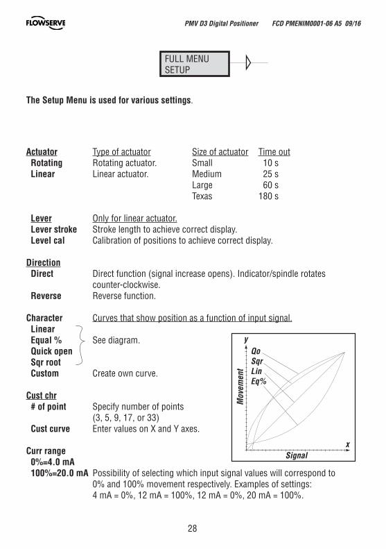
Actuator Type of actuator Size of actuator Time out Rotating Rotating actuator. Small 10 s Linear Linear actuator. Medium 25 s Large 60 s Texas 180 s
Lever Only for linear actuator. Lever stroke Stroke length to achieve correct display. Level cal Calibration of positions to achieve correct display.
Direction Direct Direct function (signal increase opens). Indicator/spindle rotates counter-clockwise. Reverse Reverse function.
Character Curves that show position as a function of input signal. Linear Equal % See diagram. Quick open Sqr root Custom Create own curve.
Cust chr # of point Specify number of points (3, 5, 9, 17, or 33) Cust curve Enter values on X and Y axes.
Curr range 0%=4.0 mA 100%=20.0 mA Possibility of selecting which input signal values will correspond to 0% and 100% movement respectively. Examples of settings: 4 mA = 0%, 12 mA = 100%, 12 mA = 0%, 20 mA = 100%.
FULL MENUSETUP
The Setup Menu is used for various settings.
QoSqrLinEq%
Signal
Mov
emen
t
x
y
PMV D3 Digital Positioner FCD PMENIM0001-06 A5 09/16
29
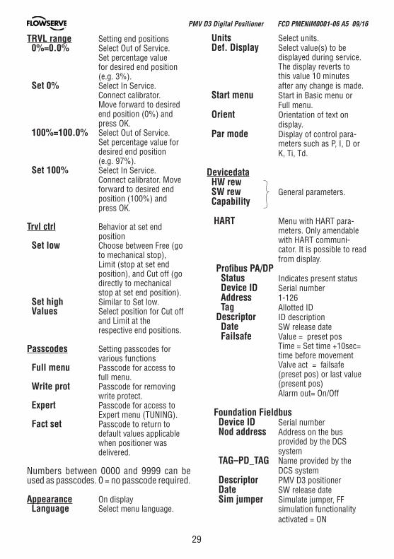
TRVL range Setting end positions 0%=0.0% Select Out of Service. Set percentage value for desired end position (e.g. 3%). Set 0% Select In Service. Connect calibrator. Move forward to desired end position (0%) and press OK. 100%=100.0% Select Out of Service. Set percentage value for desired end position (e.g. 97%). Set 100% Select In Service. Connect calibrator. Move forward to desired end position (100%) and press OK.
Trvl ctrl Behavior at set end position Set low Choose between Free (go to mechanical stop), Limit (stop at set end position), and Cut off (go directly to mechanical stop at set end position). Set high Similar to Set low. Values Select position for Cut off and Limit at the respective end positions.
Passcodes Setting passcodes for various functions Full menu Passcode for access to full menu. Write prot Passcode for removing write protect. Expert Passcode for access to Expert menu (TUNING). Fact set Passcode to return to default values applicable when positioner was delivered.
Numbers between 0000 and 9999 can be used as passcodes. 0 = no passcode required.
Appearance On display Language Select menu language.
Units Select units. Def. Display Select value(s) to be displayed during service. The display reverts to this value 10 minutes after any change is made. Start menu Start in Basic menu or Full menu. Orient Orientation of text on display. Par mode Display of control para- meters such as P, I, D or K, Ti, Td.
Devicedata HW rew SW rew General parameters. Capability HART Menu with HART para- meters. Only amendable with HART communi- cator. It is possible to read from display. Profibus PA/DP Status Indicates present status Device ID Serial number Address 1-126 Tag Allotted ID Descriptor ID description Date SW release date Failsafe Value = preset pos Time = Set time +10sec= time before movement Valve act = failsafe (preset pos) or last value (present pos) Alarm out= On/Off
Foundation Fieldbus Device ID Serial number Nod address Address on the bus provided by the DCS system TAG–PD_TAG Name provided by the DCS system Descriptor PMV D3 positioner Date SW release date Sim jumper Simulate jumper, FF simulation functionality activated = ON
PMV D3 Digital Positioner FCD PMENIM0001-06 A5 09/16
30
FULL MENUTUNING
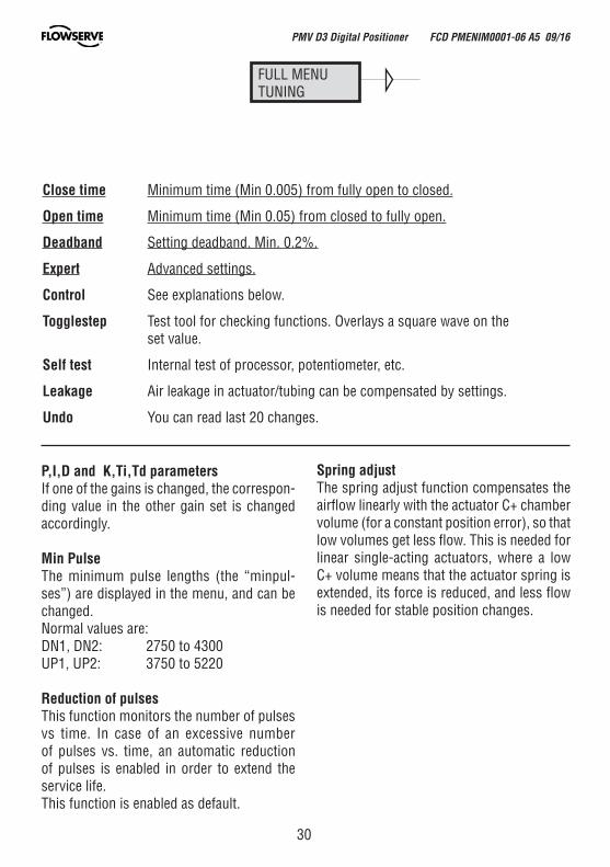
Close time Minimum time (Min 0.005) from fully open to closed.
Open time Minimum time (Min 0.05) from closed to fully open.
Deadband Setting deadband. Min. 0.2%.
Expert Advanced settings.
Control See explanations below.
Togglestep Test tool for checking functions. Overlays a square wave on the set value.
Self test Internal test of processor, potentiometer, etc.
Leakage Air leakage in actuator/tubing can be compensated by settings.
Undo You can read last 20 changes.
P,I,D and K,Ti,Td parameters If one of the gains is changed, the correspon-ding value in the other gain set is changed accordingly.
Min PulseThe minimum pulse lengths (the “minpul-ses”) are displayed in the menu, and can be changed.Normal values are:DN1, DN2: 2750 to 4300UP1, UP2: 3750 to 5220
Reduction of pulsesThis function monitors the number of pulses vs time. In case of an excessive number of pulses vs. time, an automatic reduction of pulses is enabled in order to extend the service life.This function is enabled as default.
Spring adjustThe spring adjust function compensates the airflow linearly with the actuator C+ chamber volume (for a constant position error), so that low volumes get less flow. This is needed for linear single-acting actuators, where a low C+ volume means that the actuator spring is extended, its force is reduced, and less flow is needed for stable position changes.
PMV D3 Digital Positioner FCD PMENIM0001-06 A5 09/16
31
FULL MENUALARMS
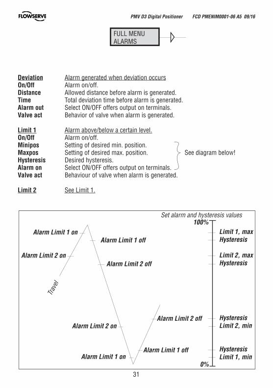
Deviation Alarm generated when deviation occursOn/Off Alarm on/off.Distance Allowed distance before alarm is generated.Time Total deviation time before alarm is generated.Alarm out Select ON/OFF offers output on terminals.Valve act Behavior of valve when alarm is generated.
Limit 1 Alarm above/below a certain level.On/Off Alarm on/off.Minipos Setting of desired min. position.Maxpos Setting of desired max. position. See diagram below!Hysteresis Desired hysteresis.Alarm on Select ON/OFF offers output on terminals.Valve act Behaviour of valve when alarm is generated.
Limit 2 See Limit 1.
Limit 1, maxHysteresis
Limit 2, maxHysteresis
HysteresisLimit 2, min
HysteresisLimit 1, min
0%
100%
Alarm Limit 1 on
Alarm Limit 2 on
Alarm Limit 1 off
Alarm Limit 2 off
Alarm Limit 2 on
Alarm Limit 1 onAlarm Limit 1 off
Alarm Limit 2 off
Trav
el
Set alarm and hysteresis values
PMV D3 Digital Positioner FCD PMENIM0001-06 A5 09/16

32
Temp Alarm based on temperatureOn/Off Temperature alarm on/off.
Low temp Temperature setting.
High temp Temperature setting.
Hysteresis Allowed hysteresis.
Alarm out Select ON/OFF offers output on terminals.
Valve act Behavior of valve when alarm is generated.
Valve act
No action Alarm generated only. Operations not affected.
Goto open C+ gives full pressure and valve moves to fully open position. Positioner changes to position Manual.
Goto close C- gives full pressure and valve moves to fully closed position. Positioner changes to position Manual.
Manual Valve stays in unchanged position. Positioner moves to position Manual.
PMV D3 Digital Positioner FCD PMENIM0001-06 A5 09/16
33
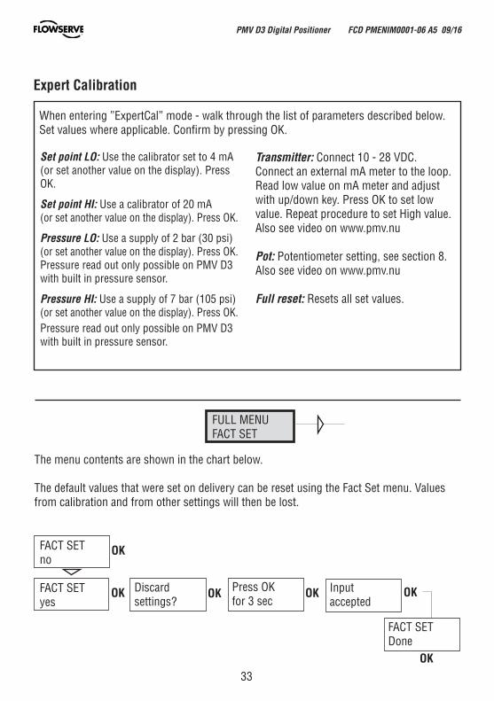
FACT SETno
FACT SETyes
OK
OK Press OKfor 3 sec
OK OKDiscardsettings?
Input accepted
OK
FACT SETDone
OK
FULL MENUFACT SET
The menu contents are shown in the chart below.
The default values that were set on delivery can be reset using the Fact Set menu. Valuesfrom calibration and from other settings will then be lost.
Set point LO: Use the calibrator set to 4 mA (or set another value on the display). Press OK.
Set point HI: Use a calibrator of 20 mA (or set another value on the display). Press OK.
Pressure LO: Use a supply of 2 bar (30 psi) (or set another value on the display). Press OK.Pressure read out only possible on PMV D3with built in pressure sensor.
Pressure HI: Use a supply of 7 bar (105 psi)(or set another value on the display). Press OK.Pressure read out only possible on PMV D3 with built in pressure sensor.
When entering ”ExpertCal” mode - walk through the list of parameters described below.Set values where applicable. Confirm by pressing OK.
Transmitter: Connect 10 - 28 VDC.Connect an external mA meter to the loop. Read low value on mA meter and adjust with up/down key. Press OK to set low value. Repeat procedure to set High value. Also see video on www.pmv.nu
Pot: Potentiometer setting, see section 8. Also see video on www.pmv.nu
Full reset: Resets all set values.
Expert Calibration
PMV D3 Digital Positioner FCD PMENIM0001-06 A5 09/16
34
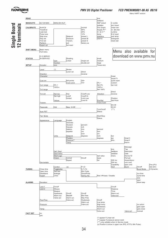
READ posset&pos
MAN/AUTO AUT,OK=MAN se
Menu HART version
lcyc nlautca P&STUA=KO,NAMset&dev acc travel
CALIBRATE ved naemhparG soPlamronlaCotuAved sba .m**rP ylppuS%05laClevarT
emitnur**-C & +C%52tset kaeLteser fo #pmet%21enut esluP
pmet rtxescitsitatsL teserptniopteSenut petSmargotsihsmralaM teserperusserPtse yalPtats teserS teserp.msnarTtse tcirF
es yrotcaftopmrofrePteser lluflac trepxE
SHIFT MENU Basic menuFull menu
O O SERVICSTATUS llamsgnitatoRECIVRES NI
type Linear single act mediumegraltca elbuodnoitcnuf
SETUP Actuator ezis-saxeTezis
Lever (*) StrokeLever cal direct
esrevernoitceriDCharacter linear
equal %nepo kciuq=0Xstniop fo#rhc tsuC
Cust curve Y0= 0% = customtoor rqs%0 teS= %0egnar rruC
=%001=%001%001 teSegnar lvrT
directTrvl ctrl Set low free Cutoff Low Direction reverse
Set high cutoff Cutoff HinoitisoPwoL timiLdetimil
tnioP teSteS/soPiH timiLseulaVdraC.snarT.msnarT
D3-3818-3DffO=0 weNdlOedocssaP
TurnOn/off (***)sutatSTSP otuA
potS/tratSedoM .liaFStatus
Appearance Language EnglishSvenskaDeutsch percentfrançais mAItaliano mm percentespañol cm mm
inch cmUnits Setpoint degrees inch bar
C darGispseergednoitisoPF darGaPk**erusserP
nivleKpmeT
Messagepos Tag
rotpircseDsop&teslpsiD .feDetaDved&tesunem tratS
DI eciveDunemeulav tsalogoL tratSrda lloPcisabffo/nOlamron.tneirO
onylbmessA ver WHllufdeppilfDevicedata SW rev univ cmd
)VP( soPdmc cepsytilibapaC)VS( teSffo/nOtsruBtraHD,I,P)x(lortnoC
TUNING cimanyD 4edoM tsruBdT,iT,KpetselggoTemit esolCesluP niMtset fleSemit nepO
emit nuretorPtoohSegakaeldnabdaeDemit elcycelbasiD / sesluP# .deRjdA gnirpSodnUtrepxE
sizestart
ALARMS Deviation Abort step
ffo/nOffo/nO1 timiLecnatsiDsopniM2 timiL
emiTsopxaMtuo mralAffo/nOffo/nOsiseretsyHtca evlaVserP niMffidxaMtuo mralA
Valve act Alarm out Max Presffo/nOsiseretsyHtca evlaVserP=soP
Alarm out Low tempnoitca onpmet hgiHtca evlaVerusserPnepo otogsiseretsyHesolc otogtuo mralApmeT
launamtca evlaVtca evlaVFACT SET no
yes(*) appear if Linear set(**) appear if pressure sensor exist(***) only settable when In Service mode(x) Position is show in upper row (PID, KTiTd, Min Pulse)
Sing
le B
oard
12 te
rmin
als
Menu also available for download on www.pmv.nu
PMV D3 Digital Positioner FCD PMENIM0001-06 A5 09/16
35
8. Maintenance/service
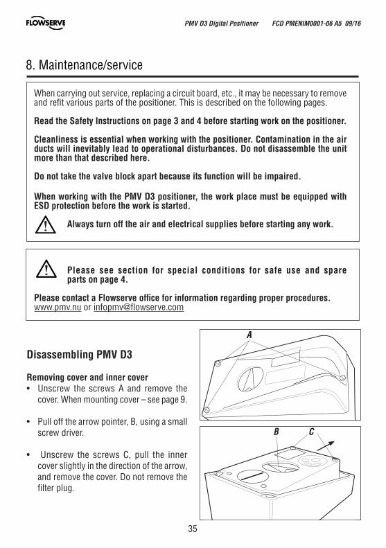
Disassembling PMV D3
Removing cover and inner cover• Unscrew the screws A and remove the
cover. When mounting cover – see page 9.
• Pull off the arrow pointer, B, using a small screw driver.
• Unscrew the screws C, pull the inner cover slightly in the direction of the arrow, and remove the cover. Do not remove the filter plug.
When carrying out service, replacing a circuit board, etc., it may be necessary to remove and refit various parts of the positioner. This is described on the following pages.
Read the Safety Instructions on page 3 and 4 before starting work on the positioner.
Cleanliness is essential when working with the positioner. Contamination in the air ducts will inevitably lead to operational disturbances. Do not disassemble the unit more than that described here.
Do not take the valve block apart because its function will be impaired.
When working with the PMV D3 positioner, the work place must be equipped with ESD protection before the work is started.
Always turn off the air and electrical supplies before starting any work.
Please see section for special conditions for safe use and spare parts on page 4.
Please contact a Flowserve office for information regarding proper procedures.www.pmv.nu or [email protected]
A
B C
PMV D3 Digital Positioner FCD PMENIM0001-06 A5 09/16
36
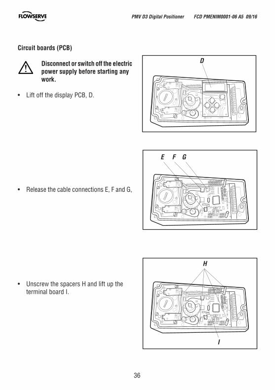
Circuit boards (PCB)
Disconnect or switch off the electric power supply before starting any work.
• Lift off the display PCB, D.
• Release the cable connections E, F and G,
• Unscrew the spacers H and lift up the terminal board I.
D
E F G
I
H
PMV D3 Digital Positioner FCD PMENIM0001-06 A5 09/16
37
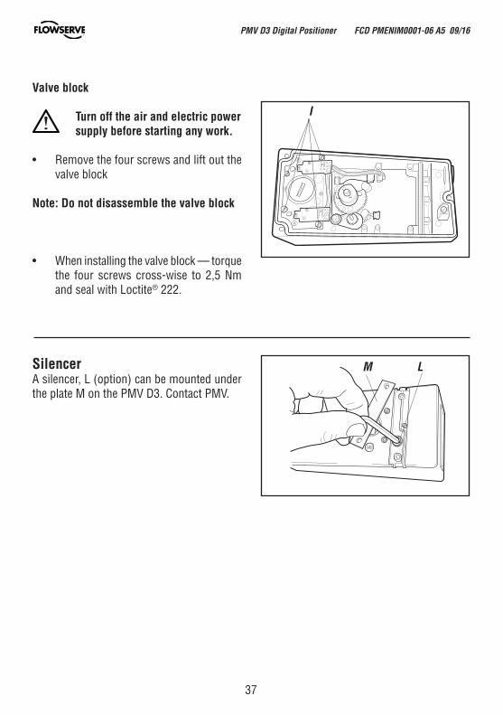
Valve block
Turn off the air and electric power supply before starting any work.
• Remove the four screws and lift out the valve block
Note: Do not disassemble the valve block
• When installing the valve block — torque the four screws cross-wise to 2,5 Nm and seal with Loctite® 222.
SilencerA silencer, L (option) can be mounted under the plate M on the PMV D3. Contact PMV.
M L
I
PMV D3 Digital Positioner FCD PMENIM0001-06 A5 09/16
38
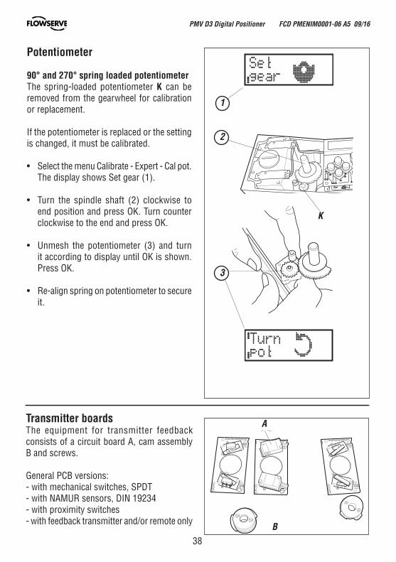
Transmitter boardsThe equipment for transmitter feedback consists of a circuit board A, cam assembly B and screws.
General PCB versions:- with mechanical switches, SPDT- with NAMUR sensors, DIN 19234- with proximity switches- with feedback transmitter and/or remote only
A
B
K
Potentiometer
90° and 270° spring loaded potentiometerThe spring-loaded potentiometer K can be removed from the gearwheel for calibration or replacement.
If the potentiometer is replaced or the setting is changed, it must be calibrated.
• Select the menu Calibrate - Expert - Cal pot. The display shows Set gear (1).
• Turn the spindle shaft (2) clockwise to end position and press OK. Turn counter clockwise to the end and press OK.
• Unmesh the potentiometer (3) and turn it according to display until OK is shown. Press OK.
• Re-align spring on potentiometer to secure it.
1
2
3
PMV D3 Digital Positioner FCD PMENIM0001-06 A5 09/16
39
B
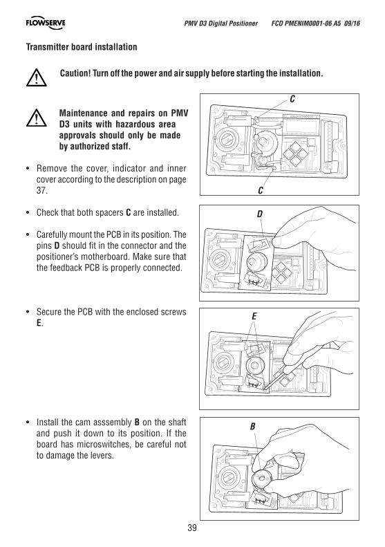
Transmitter board installation
Maintenance and repairs on PMV D3 units with hazardous area approvals should only be made by authorized staff.
• Remove the cover, indicator and inner cover according to the description on page 37.
• Check that both spacers C are installed.
• Carefully mount the PCB in its position. The pins D should fit in the connector and the positioner’s motherboard. Make sure that the feedback PCB is properly connected.
• Secure the PCB with the enclosed screws E.
• Install the cam asssembly B on the shaft and push it down to its position. If the board has microswitches, be careful not to damage the levers.
E
D
C
C
Caution! Turn off the power and air supply before starting the installation.
PMV D3 Digital Positioner FCD PMENIM0001-06 A5 09/16
40
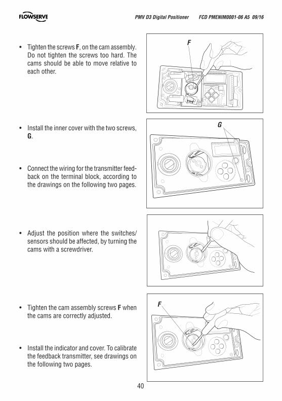
• Tighten the screws F, on the cam assembly. Do not tighten the screws too hard. The cams should be able to move relative to each other.
• Install the inner cover with the two screws, G.
• Connect the wiring for the transmitter feed-back on the terminal block, according to the drawings on the following two pages.
• Adjust the position where the switches/sensors should be affected, by turning the cams with a screwdriver.
• Tighten the cam assembly screws F when the cams are correctly adjusted.
• Install the indicator and cover. To calibrate the feedback transmitter, see drawings on the following two pages.
F
G
F
PMV D3 Digital Positioner FCD PMENIM0001-06 A5 09/16
41
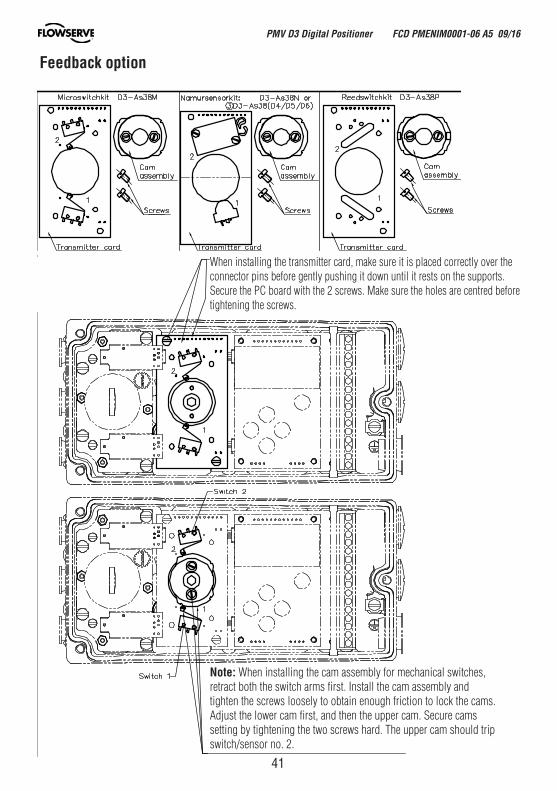
Feedback option
When installing the transmitter card, make sure it is placed correctly over the connector pins before gently pushing it down until it rests on the supports.Secure the PC board with the 2 screws. Make sure the holes are centred before tightening the screws.
Note: When installing the cam assembly for mechanical switches, retract both the switch arms first. Install the cam assembly and tighten the screws loosely to obtain enough friction to lock the cams. Adjust the lower cam first, and then the upper cam. Secure cams setting by tightening the two screws hard. The upper cam should trip switch/sensor no. 2.
PMV D3 Digital Positioner FCD PMENIM0001-06 A5 09/16
42
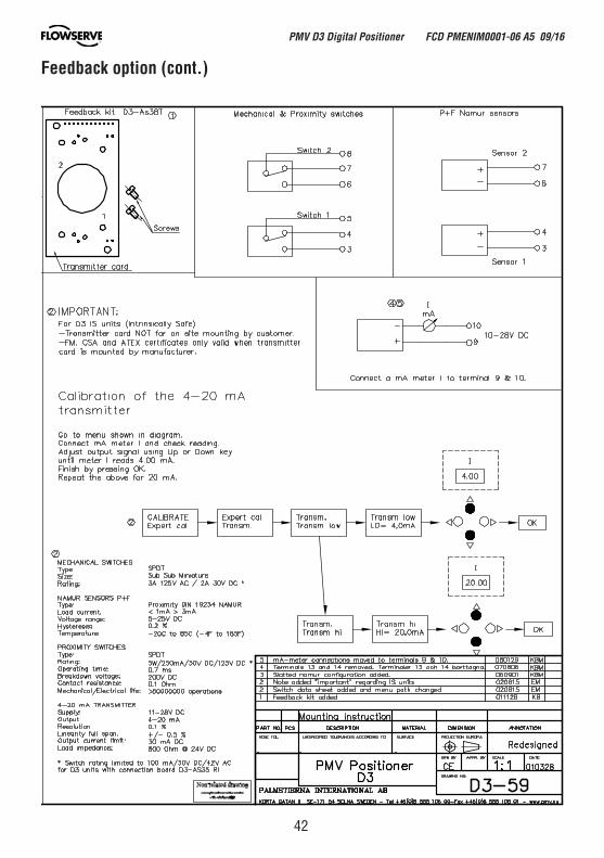
Feedback option (cont.)
PMV D3 Digital Positioner FCD PMENIM0001-06 A5 09/16
43
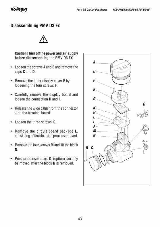
Disassembling PMV D3 Ex
Caution! Turn off the power and air supply before disassembling the PMV D3 EX
• Loosen the screws A and B and remove the caps C and D.
• Remove the inner display cover E by loosening the four screws F.
• Carefully remove the display board and loosen the connection H and I.
• Release the wide cable from the connector J on the terminal board.
• Loosen the three screws K.
• Remove the circuit board package L, consisting of terminal and processor board.
• Remove the four screws M and lift the block N.
• Pressure sensor board O, (option) can only be moved after the block N is removed.
A
D
F
E
G
KHLIJMN
B C
O
PMV D3 Digital Positioner FCD PMENIM0001-06 A5 09/16
44
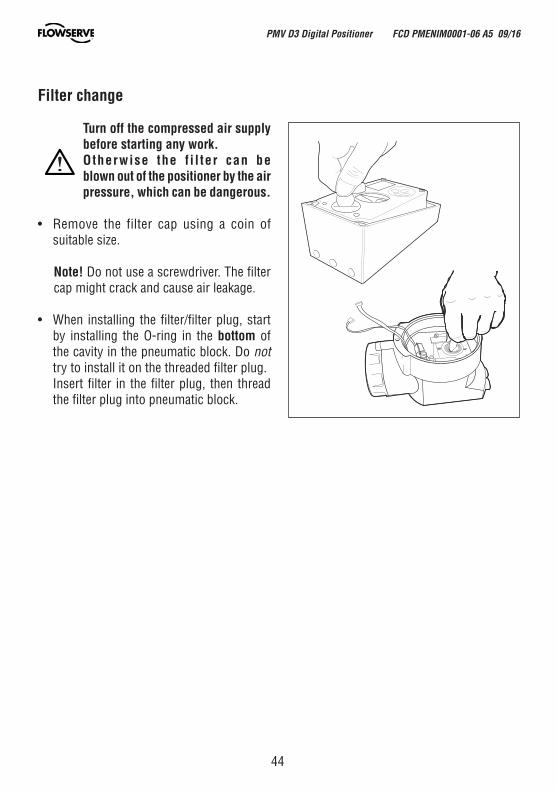
Filter change
Turn off the compressed air supply before starting any work.Otherwise the f i l ter can be blown out of the positioner by the air pressure, which can be dangerous.
• Remove the filter cap using a coin of suitable size.
Note! Do not use a screwdriver. The filter cap might crack and cause air leakage.
• When installing the filter/filter plug, start by installing the O-ring in the bottom of the cavity in the pneumatic block. Do not try to install it on the threaded filter plug.
Insert filter in the filter plug, then thread the filter plug into pneumatic block.
PMV D3 Digital Positioner FCD PMENIM0001-06 A5 09/16
45
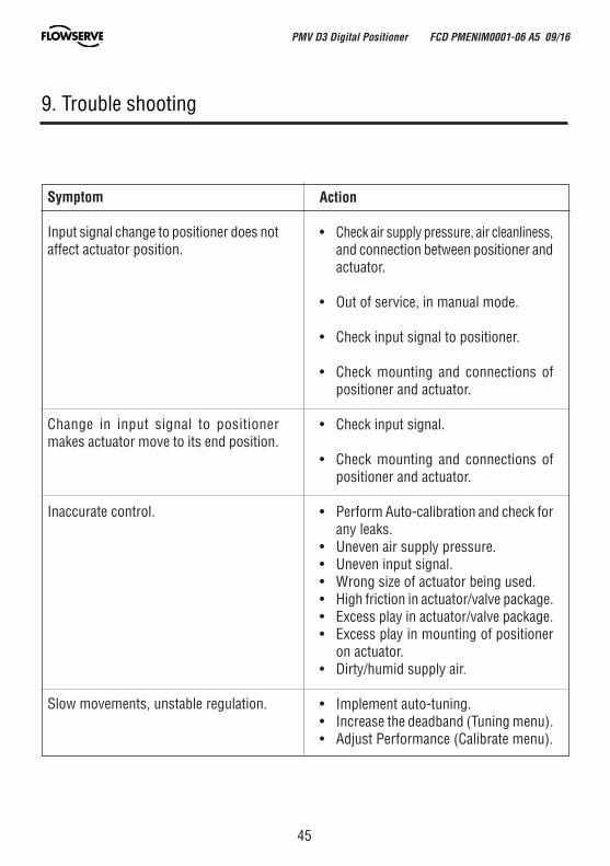
9. Trouble shooting
Symptom
Input signal change to positioner does not affect actuator position.
Change in input signal to positioner makes actuator move to its end position.
Inaccurate control.
Slow movements, unstable regulation.
Action
• Check air supply pressure, air cleanliness, and connection between positioner and actuator.
• Out of service, in manual mode.
• Check input signal to positioner.
• Check mounting and connections of positioner and actuator.
• Check input signal.
• Check mounting and connections of positioner and actuator.
• Perform Auto-calibration and check for any leaks.
• Uneven air supply pressure.• Uneven input signal.• Wrong size of actuator being used. • High friction in actuator/valve package.• Excess play in actuator/valve package.• Excess play in mounting of positioner
on actuator.• Dirty/humid supply air.
• Implement auto-tuning. • Increase the deadband (Tuning menu).• Adjust Performance (Calibrate menu).
PMV D3 Digital Positioner FCD PMENIM0001-06 A5 09/16
46
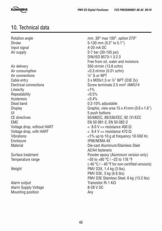
Rotation angle min. 30° max 100°, option 270°Stroke 5-130 mm (0.2” to 5.1”)Input signal 4-20 mA DCAir supply 2-7 bar (30-105 psi) DIN/ISO 8573-1 3.2.3 Free from oil, water and moisture.Air delivery 350 nl/min (13.8 scfm)Air consumption <0.3 nl/min (0.01 scfm)Air connections ¼” G or NPTCable entry 3 x M20x1,5 or ½” NPT (D3E 2x)Electrical connections Screw terminals 2.5 mm2 /AWG14Linearity <1%Repeatability <0.5%Hysteresis <0.4%Dead band 0.2-10% adjustableDisplay Graphic, view area 15 x 41mm (0.6 x 1.6”)UI 5 push buttonsCE directives 93/68EEC, 89/336/EEC, 92 /31/EECEMC EN 50 081-2, EN 50 082-2Voltage drop, without HART < 8.0 V => resistance 400 ΩVoltage drop, with HART < 9.4 V => resistance 470 ΩVibrations <1% up to 10 g at frequency 10-500 HzEnclosure IP66/NEMA 4XMaterial Die-cast Aluminum/Stainless Steel A2/A4 fastenersSurface treatment Powder epoxy (Aluminum version only)Temperature range –30 to +80 °C / –22 to 176 °F (-40 °C / – 40 °F for non-certified versions)Weight PMV D3X, 1.4 kg (3 lbs). PMV D3E, 3 kg (6.6 lbs) PMV D3E Stainless Steel, 6 kg (13.2 lbs) Alarm output Transistor Ri 1 KΩAlarm Supply Voltage 8-28 V DCMounting position Any
10. Technical data
PMV D3 Digital Positioner FCD PMENIM0001-06 A5 09/16
47
Mechanical switchesType SPDTSize Sub miniatureRating 3 A/125 VAC / 2 A/30 VDCTemp. range -30°C to 80°C (–22 °F to 180 °F)
NAMUR sensors (NJ2-V3-N)Type Proximity DIN EN 60947-5-6:2000Load current 1 mA ≤ I ≤ 3 mAVoltage range 8 VDCHysteresis 0.2 %Temp. range –25 °C to 85 °C (–13 °F to 185 °F)
Proximity switchesType SPDTRating 0.4A @ 24VDC, Max 10WOperating time Max 1.0 ms Max voltage 200 VDCContact resistance 0.2 ΩTemp. range -30 °C to 80 °C (–22 °F to 180 °F)
Slot NAMUR switches (SJ2-S1N, SJ2-SN, SJ2-N)Type Proximity DIN EN 60947-5-6:2000Load current 1 mA ≤ I ≤ 3 mAVoltage 8 VDCHysteresis 0.2 %Temp –25 °C to 85 °C (–13 °F to 185 °F)
4-20 mA transmitterSupply 11-28 VDCOutput 4-20 mAResolution 0.1 %Linearity full span +/–0.5 %Output current limit 30 mA DCLoad impedance 800 Ω @ 24 VDC
PMV D3 Digital Positioner FCD PMENIM0001-06 A5 09/16
48
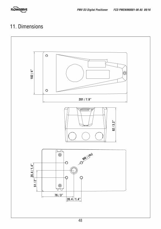
11. Dimensions
201 / 7.9”
102
/ 4”
82 /
3.2”
76 / 3”35.4 / 1.4”
35.4
/ 1.
4”51
/ 2”
M6 / (4x)
PMV D3 Digital Positioner FCD PMENIM0001-06 A5 09/16
49
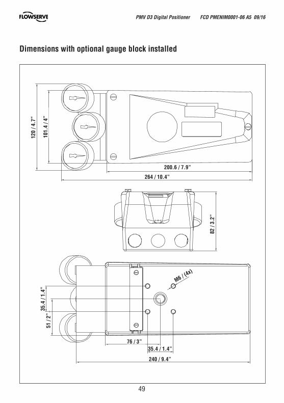
Dimensions with optional gauge block installed
264 / 10.4”
35.4 / 1.4”
35.4
/ 1.
4”
M6 / (4x)
240 / 9.4”
51 /
2”
76 / 3”
82 /
3.2”
200.6 / 7.9”
101.
4 / 4
”
120
/ 4.7
”
PMV D3 Digital Positioner FCD PMENIM0001-06 A5 09/16
50
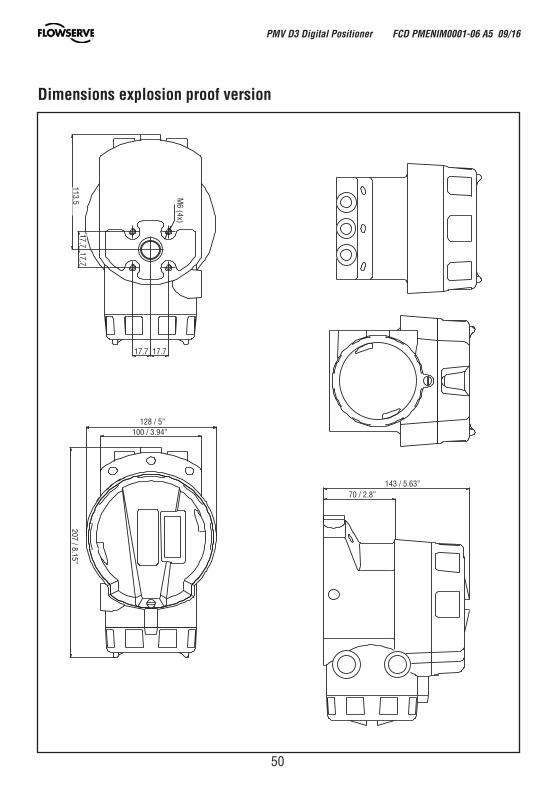
Dimensions explosion proof version
17.7 17.7
17.717.7
207 / 8.15”
128 / 5”100 / 3.94”
70 / 2.8”143 / 5.63”
113.5 M6 (4x)
PMV D3 Digital Positioner FCD PMENIM0001-06 A5 09/16
51
4 5 3 29
6
12
17
1110
11 17
16
18
7 14 13
1
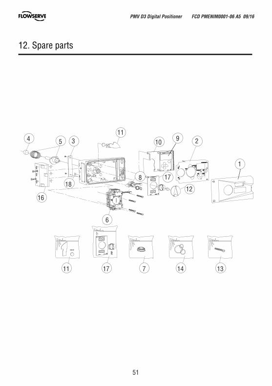
12. Spare parts
fi fl
fi fl
8
PMV D3 Digital Positioner FCD PMENIM0001-06 A5 09/16
52
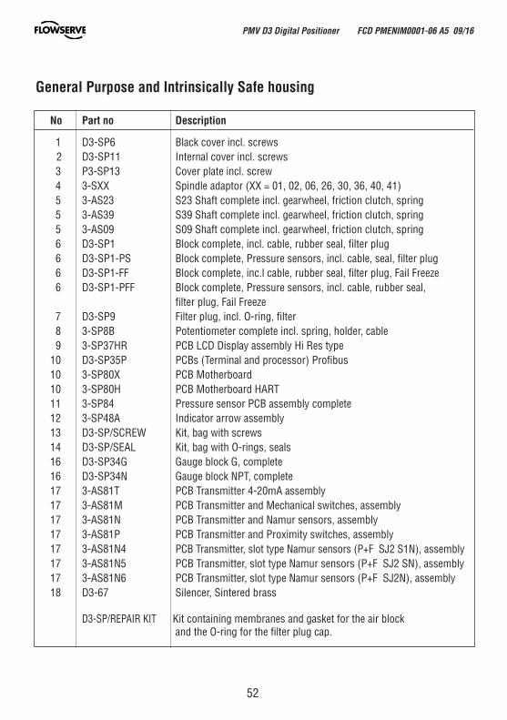
No Part no Description
1 D3-SP6 Black cover incl. screws 2 D3-SP11 Internal cover incl. screws 3 P3-SP13 Cover plate incl. screw 4 3-SXX Spindle adaptor (XX = 01, 02, 06, 26, 30, 36, 40, 41) 5 3-AS23 S23 Shaft complete incl. gearwheel, friction clutch, spring 5 3-AS39 S39 Shaft complete incl. gearwheel, friction clutch, spring 5 3-AS09 S09 Shaft complete incl. gearwheel, friction clutch, spring 6 D3-SP1 Block complete, incl. cable, rubber seal, filter plug 6 D3-SP1-PS Block complete, Pressure sensors, incl. cable, seal, filter plug 6 D3-SP1-FF Block complete, inc.l cable, rubber seal, filter plug, Fail Freeze 6 D3-SP1-PFF Block complete, Pressure sensors, incl. cable, rubber seal, filter plug, Fail Freeze 7 D3-SP9 Filter plug, incl. O-ring, filter 8 3-SP8B Potentiometer complete incl. spring, holder, cable 9 3-SP37HR PCB LCD Display assembly Hi Res type 10 D3-SP35P PCBs (Terminal and processor) Profibus 10 3-SP80X PCB Motherboard 10 3-SP80H PCB Motherboard HART 11 3-SP84 Pressure sensor PCB assembly complete 12 3-SP48A Indicator arrow assembly 13 D3-SP/SCREW Kit, bag with screws 14 D3-SP/SEAL Kit, bag with O-rings, seals 16 D3-SP34G Gauge block G, complete 16 D3-SP34N Gauge block NPT, complete 17 3-AS81T PCB Transmitter 4-20mA assembly 17 3-AS81M PCB Transmitter and Mechanical switches, assembly 17 3-AS81N PCB Transmitter and Namur sensors, assembly 17 3-AS81P PCB Transmitter and Proximity switches, assembly 17 3-AS81N4 PCB Transmitter, slot type Namur sensors (P+F SJ2 S1N), assembly 17 3-AS81N5 PCB Transmitter, slot type Namur sensors (P+F SJ2 SN), assembly 17 3-AS81N6 PCB Transmitter, slot type Namur sensors (P+F SJ2N), assembly 18 D3-67 Silencer, Sintered brass
D3-SP/REPAIR KIT Kit containing membranes and gasket for the air block and the O-ring for the filter plug cap.
General Purpose and Intrinsically Safe housing
PMV D3 Digital Positioner FCD PMENIM0001-06 A5 09/16
53
5
3
10
14
13
11
9
12 8
8
7
PMV D3 Digital Positioner FCD PMENIM0001-06 A5 09/16
54
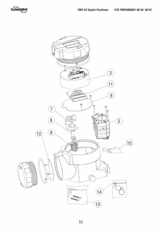
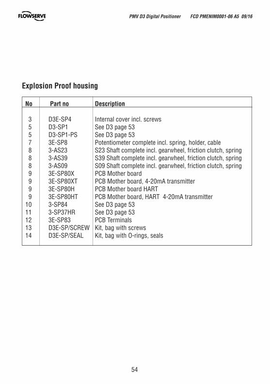
No Part no Description 3 D3E-SP4 Internal cover incl. screws 5 D3-SP1 See D3 page 53 5 D3-SP1-PS See D3 page 53 7 3E-SP8 Potentiometer complete incl. spring, holder, cable 8 3-AS23 S23 Shaft complete incl. gearwheel, friction clutch, spring 8 3-AS39 S39 Shaft complete incl. gearwheel, friction clutch, spring 8 3-AS09 S09 Shaft complete incl. gearwheel, friction clutch, spring 9 3E-SP80X PCB Mother board 9 3E-SP80XT PCB Mother board, 4-20mA transmitter 9 3E-SP80H PCB Mother board HART 9 3E-SP80HT PCB Mother board, HART 4-20mA transmitter 10 3-SP84 See D3 page 53 11 3-SP37HR See D3 page 53 12 3E-SP83 PCB Terminals 13 D3E-SP/SCREW Kit, bag with screws 14 D3E-SP/SEAL Kit, bag with O-rings, seals
Explosion Proof housing
PMV D3 Digital Positioner FCD PMENIM0001-06 A5 09/16

55
Notes
PMV D3 Digital Positioner FCD PMENIM0001-06 A5 09/16
56
PMV D3 Digital Positioner FCD PMENIM0001-06 A5 09/16
Flowserve Corporation has established industry leadership in the design and manufacture of its products. When properly selected, this Flowserve product is designed to perform its intended function safely during its useful life. However, the purchaser or user of Flowserve products should be aware that Flowserve products might be used in numerous applications under a wide variety of industrial service conditions. Although Flowserve can provide general guidelines, it cannot provide specific data and warnings for all possible applications. The purchaser/user must therefore assume the ultimate responsibility for the proper sizing and selection, installation, operation, and maintenance of Flowserve products. The purchaser/user should read and understand the (D3 Digital Positioner User Instructions) instructions included with the product, and train its employees and contractors in the safe use of Flowserve products in connection with the specific application.
While the information and specifications contained in this literature are believed to be accurate, they are supplied for informative purposes only and should not be considered certified or as a guarantee of satisfactory results by reliance thereon. Nothing contained herein is to be construed as a warranty or guarantee, express or implied, regarding any matter with respect to this product. Because Flowserve is continually improving and upgrading its product design, the specifications, dimensions and information contained herein are subject to change without notice. Should any question arise concerning these provisions, the purchaser/user should contact Flowserve Corporation at any one of its worldwide operations or offices.
For more information about Flowserve Corporation, contact www.flowserve.com or call USA 1-800-225-6989.
© February 2015, Flowserve Corporation, Irving, Texas
PMV Automation ABKorta Gatan 9SE-171 54 SolnaSWEDEN Tel: +46 (0) 8 555 106 00Fax: +46 (0) 8 555 106 01E-mail: [email protected]
GermanyFlowserve Flow Control GmbHRudolf-Plank Strasse 2D-76275 EttlingenGERMANYTel: +49 (0) 7243 103 0Fax: +49 (0) 7243 103 222E-mail: [email protected]
UKFlowserve Flow ControlBurrell Road, Haywards HeathWest Sussex RH16 1TLPhone: +44(0)1444 314400E-mail: [email protected]
ItalyFlowserve SpaVia Prealpi, 3020032 Cormano (Milano)ITALYsTel: +39 (0) 2 663 251Fax: +39 (0) 2 615 18 63E-mail: [email protected]
USA, MexicoPMV-USA14219 Westfair West DriveHouston, TX 77041, USATel: +1 281 671 9209Fax: +1 281 671 9268E-mail: [email protected]
Asia Pacific HeadquartersFlowserve Pte Ltd.No. 12 Tuas Avenue 20REPUBLIC OF SINGAPORE 638824Tel: +65 (0) 687 98900Fax: +65 (0) 686 24940E-mail: [email protected]
The NetherlandsFlowserve Flow Control BeneluxRechtzaad 174703 RC RoosendaalTHE NETHERLANDSTel: +31 (0) 30 6771946Fax: +27 (0) 30 6772471E-mail: [email protected]
flowserve.com
FCD PMENIM0001-06 A5 09/16
To find your local Flowserve representative:
To find your local Flowserve representative please use the Sales Locator System found at www.flowserve.com