planets preservation planning tool: plato 3.0
TRANSCRIPT
1
Planets Preservation Planning Tool: Plato 3.0 User Manual V1.0 June 2010
Digital content is short‐lived, yet will
often be valued in the future. How can
we keep it alive? Finding the right
action to enable future access to our
cultural heritage in a transparent way
is the task of PLATO.

2
Table of Content A. Introduction ........................................................................................................................................ 7
Digital preservation ......................................................................................................................... 7
Preservation planning ..................................................................................................................... 8
About this document ....................................................................................................................... 9
What is new in Plato 3.0? ................................................................................................................ 9
What was new in Plato 2.1? .......................................................................................................... 11
C. About Plato (Planning tool) ............................................................................................................... 15
Welcome page ................................................................................................................................... 15
The HOME screen: Entrance to Plato ................................................................................................ 17
Create a new plan .......................................................................................................................... 18
Start fast track evaluation ............................................................................................................. 20
Load Plan ....................................................................................................................................... 20
Navigation ..................................................................................................................................... 20
Plan setting .................................................................................................................................... 21
Export Plan .................................................................................................................................... 21
D. The fast‐track evaluation mode ........................................................................................................ 22
E. The planning workflow steps in Plato ............................................................................................... 23
1. Define Requirements ................................................................................................................. 23
1.1 Define Basis ............................................................................................................................. 23
1.2 Define Sample Records ............................................................................................................ 30
1.3 Identify Requirements ............................................................................................................. 34
How to specify requirements in the objective tree editor ................................................................ 37
2. Evaluate Alternatives ................................................................................................................. 46
2.1 Define Alternatives .................................................................................................................. 46
2.2 Go/No‐Go ................................................................................................................................ 48
2.3 Develop Experiments .............................................................................................................. 49
2.4 Run Experiments ..................................................................................................................... 50
2.5 Evaluate Experiments .............................................................................................................. 52
3. Analyse Results .......................................................................................................................... 55
3.1 Transform Measured Values ................................................................................................... 55
3.2 Set Importance Factors ........................................................................................................... 59
3.3 Analyse evaluation results ....................................................................................................... 60

3
4. Build Preservation Plan ............................................................................................................. 61
4.1 Create Executable Plan ............................................................................................................ 62
4.2 Define Preservation Plan ......................................................................................................... 63
4.3 Validate Preservation Plan ...................................................................................................... 64
List of Figures
Figure 1 Preservation planning environment .......................................................................................... 8
Figure 2 Visualisation of results .............................................................................................................. 9
Figure 3 Overview of Planets Preservation Planning workflow ............................................................ 12
Figure 4 Welcome page ......................................................................................................................... 16
Figure 5 The home screen ..................................................................................................................... 17
Figure 6 Load a plan .............................................................................................................................. 18
Figure 7 Possibilities to create a Plan .................................................................................................... 19
Figure 8 Create Preservation Plan ......................................................................................................... 19
Figure 9 Plato navigation ....................................................................................................................... 20
Figure 10 First entry of the toolbar ....................................................................................................... 21
Figure 11 Progress indicator .................................................................................................................. 21
Figure 12 Feedback form ....................................................................................................................... 22
Figure 13 Buttons: Save, Discard changes, save and proceed .............................................................. 22
Figure 14 Define Basis ........................................................................................................................... 23
Figure 15 Identification ......................................................................................................................... 24
Figure 16 Status ..................................................................................................................................... 25
Figure 17 Description ............................................................................................................................ 27
Figure 18 Policy tree with showing policy elements with possible scales ............................................ 29
Figure 19 Example policy tree ............................................................................................................... 29
Figure 20 Upload Policy XML ................................................................................................................. 30
Figure 21 Policies ................................................................................................................................... 30
Figure 22 Define Sample Records .......................................................................................................... 30

4
Figure 23 Collection Profile ................................................................................................................... 31
Figure 24 Sample Records ..................................................................................................................... 32
Figure 25 Characterisation of sample objects ....................................................................................... 33
Figure 26 Identify requirements ............................................................................................................ 34
Figure 27 Tree editor ............................................................................................................................. 37
Figure 28 Node description ................................................................................................................... 38
Figure 29 Node names are mandator ................................................................................................... 38
Figure 30 Mapping criteria to object properties ................................................................................... 40
Figure 31 Choosing the criterion category ............................................................................................ 41
Figure 32 Map property to criterion ..................................................................................................... 41
Figure 33 Choosing metrics ................................................................................................................... 42
Figure 34 Button Show the Fragments & Templates ............................................................................ 43
Figure 35 Selecting a template .............................................................................................................. 43
Figure 36 Saving a template .................................................................................................................. 43
Figure 37 Changing name and description of a template ..................................................................... 44
Figure 38 Saving a fragment .................................................................................................................. 44
Figure 39 Inserting a fragment .............................................................................................................. 45
Figure 40 Descriptive Information ......................................................................................................... 46
Figure 41 Define the alternatives to consider for the plan ................................................................... 46
Figure 42 CRIB Service Registry: list of potential alternatives............................................................... 47
Figure 43 Add new Alternative .............................................................................................................. 47
Figure 44 Take the Go decision ............................................................................................................. 48
Figure 45 Develop Experiments ............................................................................................................ 49
Figure 46 Run Experiments ................................................................................................................... 50
Figure 47 Result Files ............................................................................................................................. 51
Figure 48 Evaluate Experiment ............................................................................................................. 52
Figure 49 Requirements to evaluate ..................................................................................................... 53
5
Figure 50 Evaluation of requirements ................................................................................................... 53
Figure 51 Transform Measured Values ................................................................................................. 55
Figure 52 Transformation tables for different requirements ............................................................... 56
Figure 53 Transformation tables for ordinal scale ................................................................................ 56
Figure 54 Transformation table for numeric scale ................................................................................ 57
Figure 55 Interpolation of measured values ......................................................................................... 57
Figure 56 Aggregation mode for transformation .................................................................................. 57
Figure 57 Ordinal transformation examples ......................................................................................... 58
Figure 58 Transformation of numeric values ........................................................................................ 59
Figure 59 Set Importance Factors ......................................................................................................... 59
Figure 60 Set Importance Factors ......................................................................................................... 60
Figure 61 Analyse evaluation results for Preservation Plan for Papers ................................................ 61
Figure 62 Details for Changelogs ........................................................................................................... 61
Figure 63 Create Executable Plan .......................................................................................................... 62
Figure 64 Define preservation plan ....................................................................................................... 63
Figure 65 Validate plan .......................................................................................................................... 64

6
List of Tables
Table 1 Information which is on the welcome page ............................................................................. 16
Table 2 Example for the boxes in Create Preservation Plan ................................................................. 20
Table 3 Examples for boxes for Identifikation ....................................................................................... 25
Table 4 Examples for the boxes in Status .............................................................................................. 26
Table 5 Examples for the boxes for Description .................................................................................... 28
Table 6 Examples for the boxes in Collection Profile ............................................................................ 32
Table 7 Examples for the boxes in Sample Records .............................................................................. 34
Table 8 Examples for the boxes in Descriptive Information ................................................................. 46
Table 9 Examples for the boxes in Take the Go decision ...................................................................... 48
Table 10 Examples for Develop Experiments ....................................................................................... 50
Table 11 Examples for the boxes in Run Experiments .......................................................................... 51
Table 12 Examples for the boxes in Create Executable Plan / When .................................................... 63
Table 13 Examples for the boxes in Create Executable Plan / What .................................................... 63
7
A. Introduction
Digital preservation The fast changes of technologies in today's information landscape have considerably shortened the
lifespan of digital objects. While analogue objects such as photographs or books directly represent
the content, digital objects are useless without the technical environment they have been designed
for. In contrast to a book, Word documents cannot be read, a simulation cannot be re‐run and re‐
evaluated, sensor data cannot be interpreted without a suitable hardware, software and
documentation environment. Digital objects are under threat at several levels: media failure, file
format and tool obsolescence, or the loss of necessary metadata. Especially for born‐digital material
this often means that the contained information is lost completely. Digital preservation has become a
pressing challenge for any kind of IT‐related operation.
Given that a digital object needs an environment to function, we can either recreate the original
environment (emulation) or transform the object to work in different environments (migration). A
growing number of tools performing migration and emulation are available today; each tool has
particular strengths and weaknesses, and most often, there is no optimal solution. On the other
hand, requirements vary across institutions and domains, and for each setting, very specific
constraints apply that need to be considered. The process of evaluating potential solutions against
specific requirements and building a plan for preserving a given set of objects is called preservation
planning. Preservation planning is the centerpiece of the Reference Model for an Open Archival
Information System (OAIS, ISO Standard 14721:2003)1. So far, it is a mainly manual, sometimes ad‐
hoc process with little or no tool support.
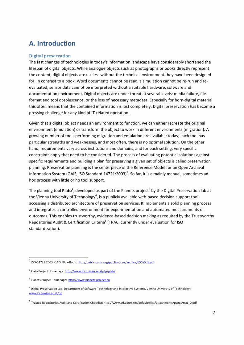
The planning tool Plato2, developed as part of the Planets project3 by the Digital Preservation lab at
the Vienna University of Technology4, is a publicly available web‐based decision support tool
accessing a distributed architecture of preservation services. It implements a solid planning process
and integrates a controlled environment for experimentation and automated measurements of
outcomes. This enables trustworthy, evidence‐based decision making as required by the Trustworthy
Repositories Audit & Certification Criteria5 (TRAC, currently under evaluation for ISO
standardization).
1 ISO‐14721:2003: OAIS, Blue‐Book: http://public.ccsds.org/publications/archive/650x0b1.pdf
2 Plato Project Homepage: http://www.ifs.tuwien.ac.at/dp/plato
3 Planets Project Homepage: http://www.planets‐project.eu
4 Digital Preservation Lab, Department of Software Technology and Interactive Systems, Vienna University of Technology:
www.ifs.tuwien.ac.at/dp
5 Trusted Repositories Audit and Certification Checklist: http://www.crl.edu/sites/default/files/attachments/pages/trac_0.pdf
8
Preservation planning To ensure digital content stays accessible and authentic for future users a plan has to be created
taking into account legal and technical constraints such as storage space, infrastructure and delivery,
copyright issues, and costs, user needs, and object characteristics.
A preservation plan defines a series of preservation actions to be taken by a responsible institution
due to an identified risk for a given set of digital objects or records (called collection). The
Preservation Plan takes into account the preservation policies, legal obligations, organisational and
technical constraints, user requirements and preservation goals and describes the preservation
context, the evaluated preservation strategies and the resulting decision for one strategy, including
the reasoning for the decision. It also specifies a series of steps or actions (called preservation action
plan) along with responsibilities and rules and conditions for execution on the collection. Provided
that the actions and their deployment as well as the technical environment allow it, this action plan is
an executable workflow definition.6
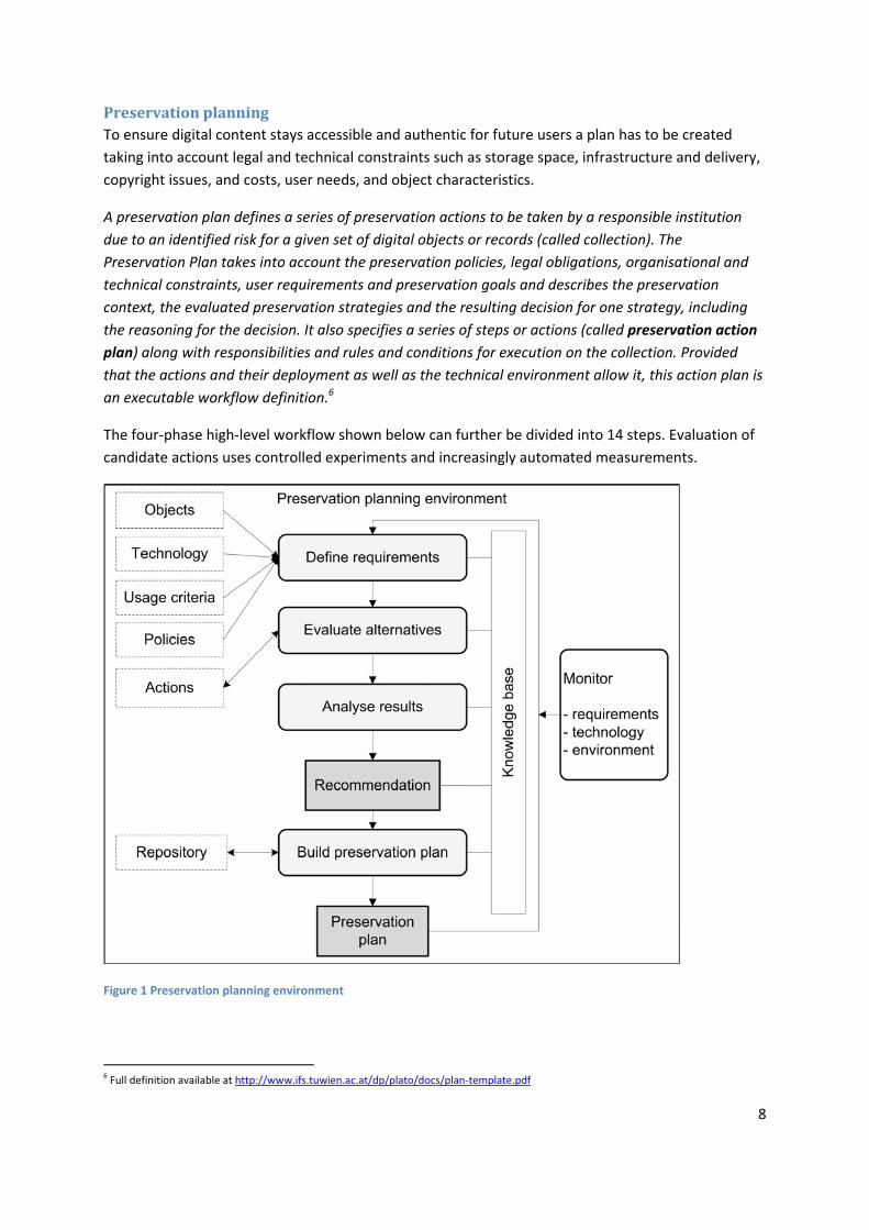
The four‐phase high‐level workflow shown below can further be divided into 14 steps. Evaluation of
candidate actions uses controlled experiments and increasingly automated measurements.
Figure 1 Preservation planning environment
6 Full definition available at http://www.ifs.tuwien.ac.at/dp/plato/docs/plan‐template.pdf

9
Potential migration and emulation tools are applied to sample content and evaluated according to a
hierarchy of requirements, based on Utility Analysis. A service‐oriented framework greatly
automates experiments and allows users to leverage various publicly available web service registries
that provide access to potential preservation action tools. Quality‐aware services measure execution
parameters and quality of the action tools and take this burden off the experimenter.
Figure 2 Visualisation of results
The result of using Plato is a complete preservation plan that can be deployed and executed.
About this document This document describes version 3.0 of the Planets Preservation Planning Tool Plato and how to use
it. Plato 3.0 implements the Planets Preservation Planning approach which is described in more detail
in the next chapter.
A deployed version of Plato can be found at http://www.ifs.tuwien.ac.at/dp/plato .
Please note: The help pages of Plato are integrated in the tool and are kept up to date with every
release.
What is new in Plato 3.0?
Automated measurements. We have developed an extensible measurement framework
to connect decision criteria to measurable properties and metrics in six categories:
1. Object outcome: Desired properties of the object such as editability, and properties
of the original that need to be preserved, such as image width.

10
2. Outcome format: Criteria on the format the objects will be stored in, such as
standardization.
3. Outcome effects: Effects induced by the preservation action, such as costs.
4. Action Runtime: Runtime properties such as used time and memory.
5. Action static: Action properties such as licensing costs and quality of documentation
of a specific tool.
6. Action Judgement: Properties that need to be judged, such as usability.
Fast‐track evaluation. We have added a fast evaluation workflow that leads from a few
basic assumptions to a quick evaluation of potential solutions in just three steps.
Remote emulation. The remote emulation service powered by GRATE is now integrated
in PLATO and available through the Planets service registry. Please note that this is
running on a different server than Plato and be patient.
Improved knowledge base. The knowledge base for criteria and templates has been
improved and its usage eased.
Integrated FITS, the File Information ToolSet. FITS (http://code.google.com/p/fits) not
only includes and homogenizes the output of characterization tools such as DROID
(https://sourceforge.net/projects/droid) and JHove (http://hul.harvard.edu/jhove), but
also includes additional extractors such as the ExifTool
(http://www.sno.phy.queensu.ca/~phil/exiftool) and others. It is used to describe sample
objects and support the automated evaluation of experiments.
Integrated P2, the Semantic web registry. P2 is a format registry that is semantically
enhanced and contains information to specifically support the process of digital
preservation. To increase the number of alternative actions offered and allow automated
format evaluation through the measurement framework, we have included 44.000 facts
about formats as they are described in the semantic web registry P2. This also enables
querying tools available that are able to convert a certain format but are not contained in
the service registries since they have not been wrapped.
Ready for ePrints. Plato can now construct preservation plans that are understood by
ePrints (http://www.eprints.org). The repository acts upon a preservation plan created in
Plato, i.e. automatically carry out the recommended preservation action.
There is a number of small improvements scattered across the tool, often addressing
feedback we received from the user community. One example is the new option of
downloading the requirements tree to edit it on the client using the mind mapping tool
Freemind. You can thus do round‐trip editing using Freemind and the planning tool.
11
What was new in Plato 2.1? As an intermediary release following version 2.0, we released Plato 2.1 in late 2009. The main new
features of Plato 2.1 were:
Sensitivity analysis. We have implemented sensitivity analysis to visualise criteria that are
sensitive to variations in the weightings.
Objective tree editors and knowledge base. We have redesigned the user interface for the
objective trees and come up with a much easier to use and much faster editor for the
knowledge base.
Jhove. We have integrated JHove, including a neat visual side‐by‐side comparison feature for
migrated sample objects to support visual evaluation.
Quality‐aware migration services. We have made a prototype registry containing quality‐
aware migration services available through Plato, featuring automated evaluation of some of
the requirements. These migration service measure quality and performance (time and
memory) and provide this information together with the result. Corresponding publications
about this technology can be found on the documentation page.Navigation structure. We
have introduced a home screen providing a central point of entry.
Executable preservation plan. Plato 2.1 creates an executable preservation plan in XML,
which can be run in the Planets workflow execution engine.
Service Integration. Updated access to Planets migration services.
Scalability. Previously, it was not feasible to upload large sample objects to create a
preservation plan, due to memory limitations. We have worked on this issue and are now
supporting sample objects sets up to (roughly) 200MB per plan.
Policy definition. You can now define your policies once and each preservation plan you
create will be using these policies.
Please note: Plato is still ongoing development and will continuously be improved and enhanced. In
most cases an update of Plato also comes with a database update which might reset the database’s
content. However, Plato also supports import and export of all preservation plans developed in Plato.
A Preservation plan can be exported as an XML file and downloaded as such, and uploaded to a new
version of the planning tool. Preservation plans are automatically upgraded to the newest version
with every release.
Working on a preservation plan can seamlessly be continued after importing a plan.

12
B. The planning workflow
Figure 3 Overview of Planets Preservation Planning workflow
Figure 1 Overview of PLANETS Preservation Planning workflow
The Planets preservation planning workflow consists of four main stages:
1. Define requirements
2. Evaluate alternatives
3. Consider results
4. Build preservation plan
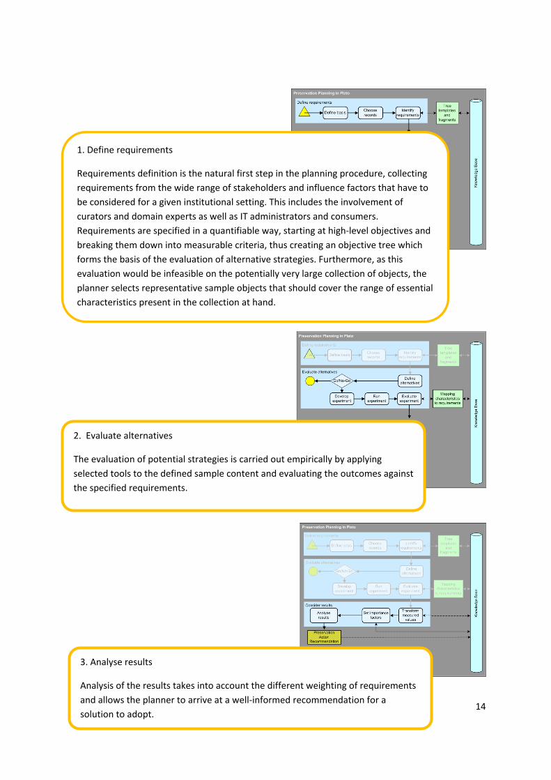
Figure 2 shows the screens of the planning tool to illustrate the progression through the
workflow.

13
Figure 2 Screens of the workflow steps
14
1. Define requirements
Requirements definition is the natural first step in the planning procedure, collecting
requirements from the wide range of stakeholders and influence factors that have to
be considered for a given institutional setting. This includes the involvement of
curators and domain experts as well as IT administrators and consumers.
Requirements are specified in a quantifiable way, starting at high‐level objectives and
breaking them down into measurable criteria, thus creating an objective tree which
forms the basis of the evaluation of alternative strategies. Furthermore, as this
evaluation would be infeasible on the potentially very large collection of objects, the
planner selects representative sample objects that should cover the range of essential
characteristics present in the collection at hand.
2. Evaluate alternatives
The evaluation of potential strategies is carried out empirically by applying
selected tools to the defined sample content and evaluating the outcomes against
the specified requirements.
3. Analyse results
Analysis of the results takes into account the different weighting of requirements
and allows the planner to arrive at a well‐informed recommendation for a
solution to adopt.

15
C. About Plato (Planning tool)
Welcome page
4. Build preservation plan
A preservation plan defines a series of preservation actions to be taken by a
responsible institution due to an identified risk for a given set of digital objects or
records (called collection).
Five sections for introducing Plato

16
Figure 4 Welcome page
The first page (Figure 2) of Plato is a welcome page presenting detailed information about Plato. The information is subdivided into 5 sections:
Introduction Documentation Case Studies Events History
What is Plato Introductory material
Publications
Video Games Upcoming Events
Release history and changes
News Scientific Papers Interactive Multimedia Art
Past Events Awards
What is new? Plan Deliverables Electronic Theses and Dissertations
Feedback and browser compatibility
Scanned books
Scanned newspapers
Scanned yearbooks
Bitstream Preservation of Digital Photographs
Table 1 Information which is on the welcome page
To enter Plato, you have to click the link: ‘Click here to enter Plato’. In the login screen, you have to enter your credentials. If you don't have an account yet, you can create it right there.

17
The HOME screen: Entrance to Plato
Figure 5 The home screen
The home screen provides a very short introduction text with further links and, depending on your role, allows you to access several pages:
a) Lists of your personal plans, published plans, or (in case you are administrator) all plans b) Create a new plan c) Define your organisation's policy model d) Access the documentation pages e) Start a fast‐track evaluation
If you choose one of the plan lists, you arrive at a screen like the following:
b
c
d
a
e

18
Figure 6 Load a plan
Here you can
load an existing plan, [see a]
create a new DEMO plan, [see b]
or load plans from previously exported plans in XML [see c]
Create a new plan A new plan can be started from scratch by either choosing ‘New Plan’ from the menu or clicking the ‘New Plan’ button on the ‘Load plan’ screen.
b
a
c

19
Figure 7 Possibilities to create a Plan
After you have clicked the button for a new plan a new site will open.
Figure 8 Create Preservation Plan
Name of the text fields Examples which could be filled in the text fields
Plan name Preservation Plan for Papers
Digital Preservation of Console Video Games (SNES)
Plan description This is an example plan. The plan was created for the DELOS Summer School 2008 and revised afterwards.
Data for SNES preservation from the diploma thesis "Digital Preservation of Console Video Games"
Responsible planner Hans Hofman
If the plan should not be
visible for other Plato users,
please check the box ‘Private‘
On the menu bar you can find:
‘New Plan‘, which you can
choose to start a preservation
plan from scratch.
Or you use this button.
20
Organisation National Library
Vienna University of Technology
Table 2 Example for the boxes in Create Preservation Plan
After filling out the boxes continue by clicking the button: Create Plan
Start fast track evaluation This starts like a new plan, but you will be directed through a simplified, highly‐automated three‐step
procedure that results in a quick analysis of potential actions for a set of files that you upload. From
there, you can continue to creating a full plan or leave the fast‐track evaluation as it is. See Section D
for details.
Load Plan After logging into Plato, a list of stored plans is provided including the ID of Plan’s name, a
description and the author(s) name(s). A plan can be loaded with the ‘Load’ button on the right side.
Loading a plan locks it, closing unlocks it again. When loading an existing plan, you will be forwarded
to the workflow step corresponding to the plan’s state.
Navigation
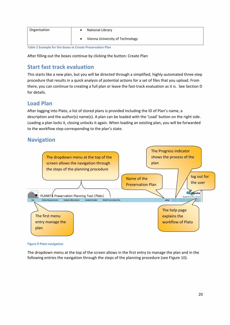
Figure 9 Plato navigation
The dropdown menu at the top of the screen allows in the first entry to manage the plan and in the following entries the navigation through the steps of the planning procedure (see Figure 10).
log out for
the user
The help page
explains the
workflow of Plato
The dropdown menu at the top of the
screen allows the navigation through
the steps of the planning procedure
The first menu
entry manage the
plan
Name of the
Preservation Plan
The Progress indicator
shows the process of the
plan

21
Figure 10 First entry of the toolbar
The first entry of the toolbar manages the plans, it includes: Plan setting
It provides basic security options that you may use to protect, unprotect and delete plans that are
created. There is also the option to upload the final report so that other users are able to see it at the
Site: “Load page” These options are only available to the user who created this plan.
Export Plan (Only available if a plan is opened.)
Exports the plan as an XML file.
Close Plan (Only available if a plan is opened.)
Closes the current plan and redirects to the Create New Plan/Load Plan page
Figure 11 Progress indicator
On the right side of the Plato navigation bar the name of the plan is shown (see Figure 11). A Progress indicator shows the process of the plan. The progress indicator shows the plan’s state, how far the plan has progressed. It shows which steps in the workflow have already been completed (dark circles). Moving the mouse over the indicator shows the name of the currently reached state as shown in the figure above. Above the progress bar are the “log out” and help functions and a link to a feedback form.
‘Plan’ , the first entry of the
menu bar, with its dropdown

22
Figure 12 Feedback form
We very much value your feedback, so please take the opportunity to let us know your thoughts!
Figure 13 Buttons: Save, Discard changes, save and proceed
Each page of the workflow contains the buttons ‘Save’, ‘Discard changes’ and ‘Save and proceed’. The save button stores the current plan in the database. The ‘discard changes’ button restores the plan state of the last saving.
It is possible to easily navigate within workflow steps that are completed, i.e. have been passed by clicking ‘Save and proceed’. The plan’s state will be reset if you click either ‘Save’ or ‘Save and proceed’.
The next step of the workflow can be reached through ‘Save and proceed’. Plato validates the input and proceeds to the next workflow step if valid. Any validation errors that occurred will be indicated and can be corrected.
D. The fast‐track evaluation mode To allow a quick evaluation that leads to first results within a few steps, there is a fast‐track
evaluation mode in Plato 3, which contains of three stripped‐down steps:
1. Define requirements consists of a few basic descriptions, sample object upload and
choosing a template tree. You cannot edit this tree at the moment. The tree further
includes the transformation settings.
Currently, the selection of trees
2. Evaluate alternatives lists all components that are readily applicable to the sample
objects uploaded. You can remove the alternatives that you don’t want to include in
23
the evaluation. After running the experiments, you can evaluate the criteria in the
lower part, invoking the evaluation plugins for each criterion.
3. Analyse results displays the aggregated results, similarly to the planning workflow.
If you want to continue investigation or change any of the settings such as transformation,
criteria, weighting, etc., you can create a plan based on this evaluation result. This will lead
you into the planning workflow, with the fast‐track evaluation results as a guidance that you
can refine and adapt to your needs.
This is a new feature that we added upon numerous requests. We had to strip down a
lot of the flexibility of the planning workflow to enable a fast evaluation. Please let us know
what you think about the current procedure and whether you think there is anything that
should be added back!
E. The planning workflow steps in Plato
1. Define Requirements The first phase of the workflow lays out the cornerstones of the planning endeavour. It starts with
collecting and documenting the influence factors and constraints on possible actions and procedures,
then describes the set of objects under consideration and finally defines the complete set of
requirements to be taken into account.
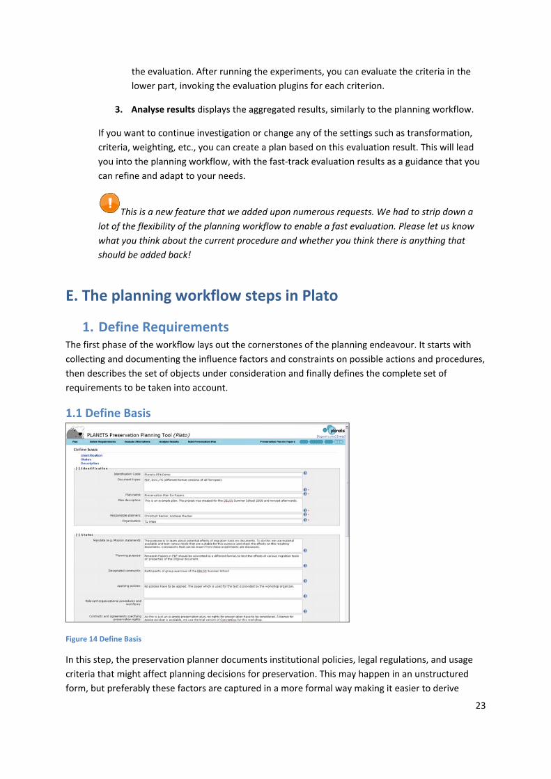
1.1 Define Basis
Figure 14 Define Basis
In this step, the preservation planner documents institutional policies, legal regulations, and usage
criteria that might affect planning decisions for preservation. This may happen in an unstructured
form, but preferably these factors are captured in a more formal way making it easier to derive

24
decisions in the respective workflow steps. Examples include policies defining permitted file formats
for ingest, and policies related to intellectual property right and legal access regulations. Further
important policy elements pertain to characteristics of the preservation action, whether preservation
actions that are open source shall be preferred or if just a specific preservation strategy may be
applied, such as emulation. This might be possible in cases where the institution doesn’t have the
copyright and thus any modifications of the digital object are prohibited. Furthermore, the event that
led to the planning procedure is documented.
1.1.1 Identification
Figure 15 Identification
A preservation plan should be uniquely identified so that it can easily be referred to and retrieved.
Type Examples
Identification code: Planets‐PP4‐Demo
ARCH‐COLL‐1299
Document types
PDF, DOC, PS, (different format versions of all file types)
Digital Data from Cartridges of Super Nintendo Entertainment
System (SNES) video games (Binary Streams)
The material exclusively consists of GIF masters, each a
scanned page or part of a yearbook.
Plan name
Preservation Plan for Papers
Digital Preservation of Console Video Games (SNES)
Plan description The preservation plan looks at the yearbook material that
has recently (end 2008) been transferred from LTO tape to
HDD storage on the Digital Preservation Teams SAN
storage unit for content stabilization. We want to evaluate
the file format for the master images and ensure that it is
suitable for long term preservation.
Data for SNES preservation from the diploma thesis "Digital

25
Preservation of Console Video Games"
Responsible planners Christoph Becker
Mark Guttenbrunner
Organisation Vienna University of Technology
The State and University Library
Table 3 Examples for boxes for Identifikation
1.1.2 Status
Figure 16 Status
The status of a plan includes both the planning progress – whether a plan is currently being defined,
awaiting approval, or already has been deployed and is active – and the triggers which have led to
the definition or refinement of the plan.
Type Examples
Mandate (e.g. Mission statement)
The mission of The State and University Library is to
preserve our states cultural heritage in the form of any
publication, whether it is printed or recorded, for the
future.
Planning purpose The purpose of this plan is to find a strategy on how to
preserve this collection for the future, i.e. choose a tool to
handle our collection with. The tool must be compatible
with our existing hardware and software infrastructure, to
install it within our server and network environment. The
files haven't been touched for several years now and no
detailed description exists. However, The State and
University Library has to ensure its accessibility for the next

26
years.
The library has the legal obligation to preserve every
published console video game like national libraries are
obliged to preserve publications on paper and offer
possibilities to display these games to the public.
Designated community
General public
The target audience is visitors of the library. It is not
necessary to publish the collection online. Access to games
from the library collection to experience the games original
look & feel should be possible for the public. Access to
original media shall not be necessary to avoid damage to
rare specimen.
Applying policies No policies have to be applied. The paper which is used for
the test is provided by the workshop organizer.
For legal reasons only games physically in the possession of
the library are preserved. This is because of copyright
restrictions. The archive doesn’t hold the copyright for the
rest of the collection.
See policy model
Relevant organisational procedures
and workflows
Library account is needed for access.
Plan has to be presented and approved by the vice board
Contracts and agreements
specifying preservation rights
The institution has the necessary right to change the object,
which might be necessary for migration.
Copyright held for the physical material. Legal mandate
implies that transforming logical representation of the
content is allowed.
Designated community
Participants of group exercises of the DELOS Summer School
The target audience is visitors of the library. It is not
necessary to publish the collection online. Access to games
from the library collection to experience the games original
look & feel should be possible for the public. Access to
original media shall not be necessary to avoid damage to
rare specimen.
Table 4 Examples for the boxes in Status

27
1.1.3 Description
Figure 17 Description
New Collection
This is the most common event, where a preservation plan is created from scratch for a new
collection, for which no plan was previously defined.
Changed Collection Profile
Changes in the collection profile of an existing collection may require a revision of existing
preservation plan. Examples for changes in the collection profile are newly accepted object formats
or significant changes in collection size. It is the responsibility of technology watch functions to
ensure that these triggers are actually fired; the corresponding events should then be recorded in the
planning documentation.
Changed Environment
The environment of a preservation plan consists of the technical environment, the designated
communities and the host institution. Changes in the environment can lead to a change in
preferences, for example with respect to the system context in which a preservation action needs to
operate. They might also imply a change in factors which influence existing preservation plans, for
example changed prices for hardware or software. Other changes are the availability of new
preservation strategies or obsolescence of object formats which are used in an existing preservation
plan. Changes in the environment require a revision of existing preservation plans, while the
objectives for the evaluation usually will remain unchanged.
Changed Objective
Changes and developments in the environment can change the objectives for preservation
evaluation over time. In this case it is necessary to evaluate existing preservation plans against
changed objectives. Examples for these changes are technology developments or changes in high‐
level policies or legal obligations that have an impact on preferences and objectives. Changes in the
designated community may also effect the goals and objectives.

28
Periodic Review
Periodical reviews of existing preservation plans are needed to continually verify the appropriateness
of plans, and to improve and further develop existing plans. A periodic review should re‐iterate the
planning activity taking into account new developed preservation strategies, and seek to verify and
potentially improve existing plans.
Type Examples
Relations No previous preservation plans for this
purpose exist, so there are no relations to
other plans and no triggers why a related
plan has to be revised.
No previous attempts to preserve these
kinds of documents have been made.
New Collection
Periodic Review
Changed Objective
Charged Collection Profile
Changed Environment Changed hardware environment: carrier refresh from
LTO tape to HDD (on the Digital Preservation Team
SAN). We see this as a very good opportunity to look
at the file format for the master images and ensure
that it is suitable for long term preservation.
Table 5 Examples for the boxes for Description
1.1.4 Policies
Why policies?
Organizations differ in many ways, type, size, direction, just to to name a few. That's why apart from
technical and intellectual properties of digital objects also the strategy, policy, goals and constraints
of the institution are an integral part of the preservation plan.
Usually organizations have created documents describing their policies, strategies, workflows, plans,
and goals to provide guidance.
The policies template
In the course of the Planets project a conceptual model of organizational digital preservation policies
and strategies has been created. It incorporates relevant organisational characteristics and strategic
directions to support the planning process in digital preservation projects.
Relevant policies have been structured in tree form which can be used as a template for defining
your organizational policies.
How to create a policy tree
Based on the policy tree you can model your policies by replacing the leaves, which denote the scale

29
of the policy, by their actual values. You should remove policies you don't have in place by simply
removing the node forming the policy.
In the tree, policies have been grouped into several levels, as for instance shown in the screenshot
below. The screenshot shows policies pertaining to Preservation Action. Leaves in the tree denote
scales the particular policy can be measured in. Policy Preservation Action must be emulation can be
answered either Yes, or No.
Figure 18 Policy tree with showing policy elements with possible scales
After all scales have been replaced by their actual values, the policy tree might look like follows:
Figure 19 Example policy tree
Upload the policy XML file
The workflow step 'Define Basis' allows to upload the policy tree which has been saved as Freemind
file (.mm).
30
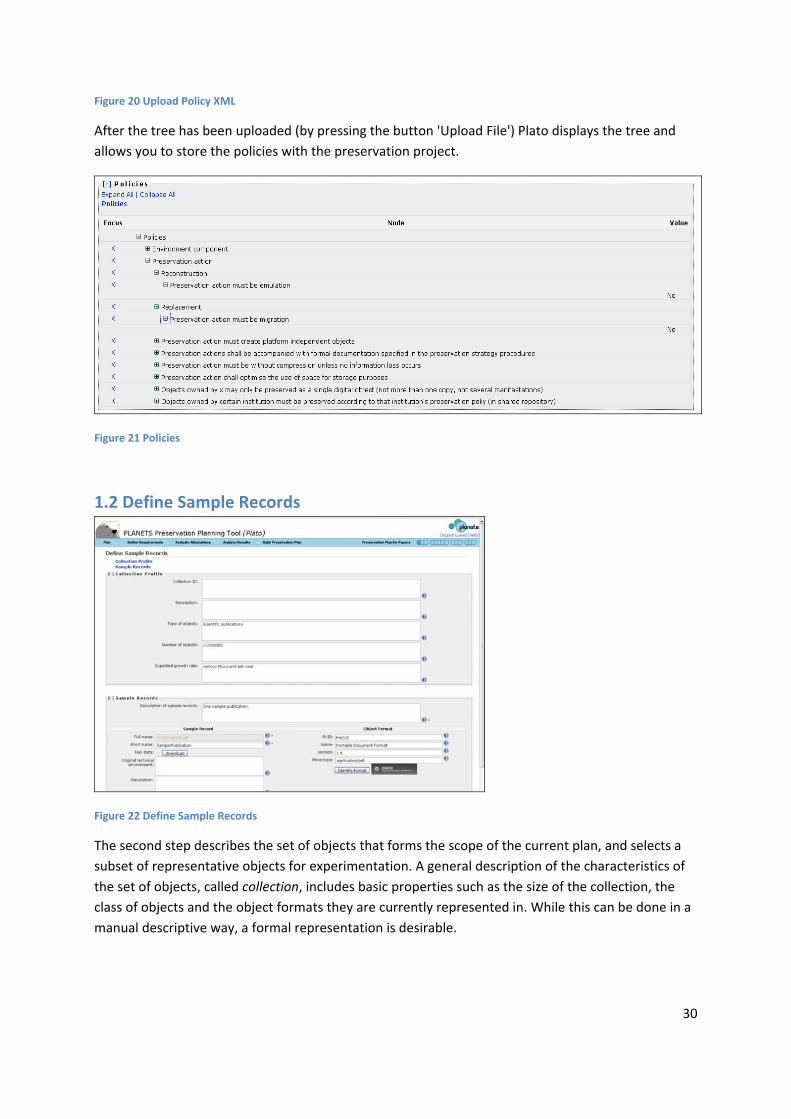
Figure 20 Upload Policy XML
After the tree has been uploaded (by pressing the button 'Upload File') Plato displays the tree and
allows you to store the policies with the preservation project.
Figure 21 Policies
1.2 Define Sample Records
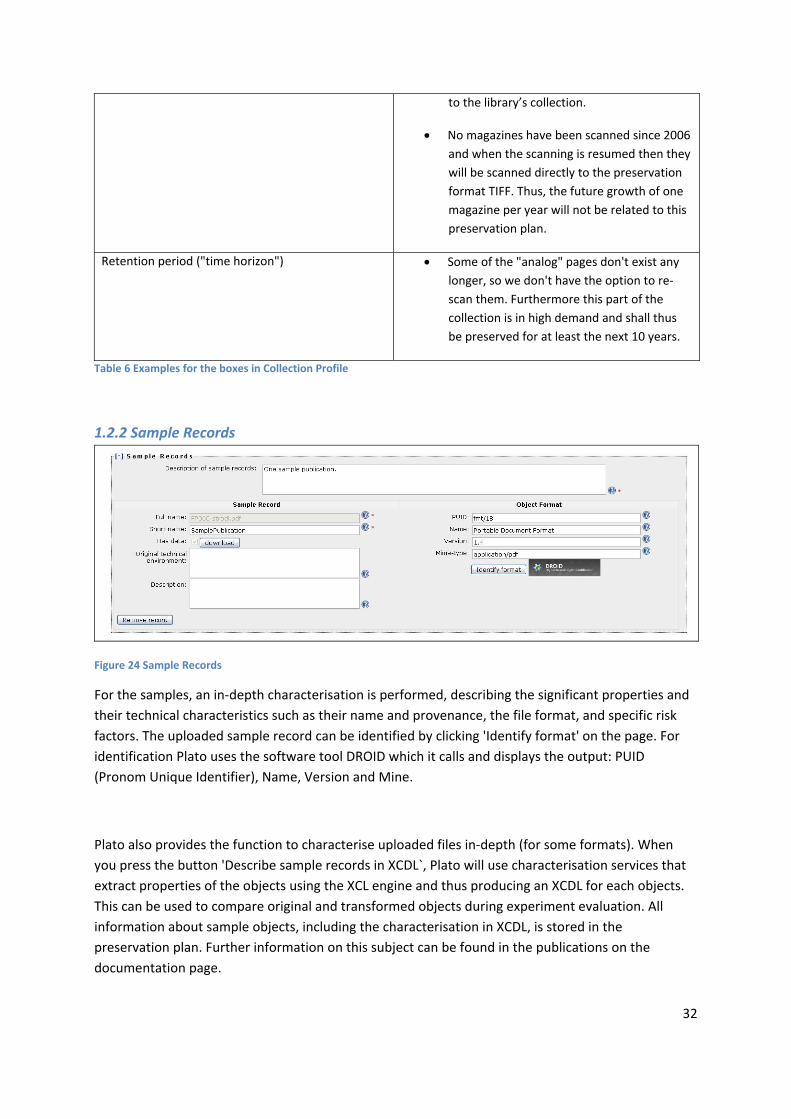
Figure 22 Define Sample Records
The second step describes the set of objects that forms the scope of the current plan, and selects a
subset of representative objects for experimentation. A general description of the characteristics of
the set of objects, called collection, includes basic properties such as the size of the collection, the
class of objects and the object formats they are currently represented in. While this can be done in a
manual descriptive way, a formal representation is desirable.

31
1.2.1 Collection Profile
Figure 23 Collection Profile
Collection profiling tools can provide automated descriptions of the technical characteristics of
objects. Characteristics of interest include object formats, file sizes and their variation within the
collection, but also aspects such as an assessment of the risks of each object type and each object,
thus leading to a risk profile of the collection. As a complete evaluation of the quality of preservation
action tools is infeasible on the potentially very large collection of objects, the planner selects
representative sample objects that should cover the range of essential characteristics present in the
collection at hand. To reduce effort to a minimum, this subset should be as small as possible.
Type Examples
Collection ID COLLECTION‐12‐2008
Yearbook‐collection‐TSL‐1200
Description Physical collection of Cartridges for the
Nintendo SNES which have been transferred
to binary streams.
The first part of the yearbook collection of
the car periodical. This part contains the
yearbooks published in the years 1965‐1989.
Type of objects Scientific publications in PDF
This part of the collection consists of GIF
files.
Digital Data from Cartridges of Super
Nintendo Entertainment System (SNES)
video games (Binary Streams).
Number of objects >1000000
1000
Expected growth rate Slow. Occasionally new games can be added
32
to the library’s collection.
No magazines have been scanned since 2006
and when the scanning is resumed then they
will be scanned directly to the preservation
format TIFF. Thus, the future growth of one
magazine per year will not be related to this
preservation plan.
Retention period ("time horizon") Some of the "analog" pages don't exist any
longer, so we don't have the option to re‐
scan them. Furthermore this part of the
collection is in high demand and shall thus
be preserved for at least the next 10 years.
Table 6 Examples for the boxes in Collection Profile
1.2.2 Sample Records
Figure 24 Sample Records
For the samples, an in‐depth characterisation is performed, describing the significant properties and
their technical characteristics such as their name and provenance, the file format, and specific risk
factors. The uploaded sample record can be identified by clicking 'Identify format' on the page. For
identification Plato uses the software tool DROID which it calls and displays the output: PUID
(Pronom Unique Identifier), Name, Version and Mine.
Plato also provides the function to characterise uploaded files in‐depth (for some formats). When
you press the button 'Describe sample records in XCDL`, Plato will use characterisation services that
extract properties of the objects using the XCL engine and thus producing an XCDL for each objects.
This can be used to compare original and transformed objects during experiment evaluation. All
information about sample objects, including the characterisation in XCDL, is stored in the
preservation plan. Further information on this subject can be found in the publications on the
documentation page.

33
Another integrated well‐known characterisation tool is JHove. The screenshot below shows the tree
view you get when you click the "View characteristics" button in Plato.
Figure 25 Characterisation of sample objects
Type Examples
Description of sample records The sample pages are taken from the 1965, 1971,
1977, 1983 and 1989 year books. The quality of
these pages is quite similar and so is it for the rest
of this part of the collection as it was scanned as
one batch. However, the sample images were
selected from different years in order to increase
the probability for differences in the image
quality, as the paper and/or print quality of the
magazines may have changed over the years.
Sample Record: Full name Very large publication containing > 20 figures.
Sample Record: Short name Very large publication
Sample Record: Original technical
environment
Sample Record: Description This is our larges publication file we have in our
collection. It contains a lot of figures, tables and
equations.
Randomly selected image to see if there would be

34
any difference in the print quality since 1983.
Object Format: PUID Fmt/18
fmt/4
Object Format: Name Portable Document Format
Graphics Interchange Format
Object Format: Version 1.4
1989a
Object Format: Mime‐type image/gif
Table 7 Examples for the boxes in Sample Records
1.3 Identify Requirements
Figure 26 Identify requirements
Requirements definition is the heart of preservation planning. It is the basis for the decisions to be
taken and documents the priorities and preferences of the institution. Requirements are collected
from the wide range of stakeholders and influence factors that have to be considered for a given

35
institutional setting. This may include the involvement of curators and domain experts as well as IT
administrators and consumers.
1.3.1 Objective Tree
The requirements are specified in a quantifiable way, starting at high‐level objectives and breaking
them down into measurable criteria, thus creating an objective tree which forms the basis of the
evaluation of alternative strategies. This step has proven to be the most critical and complicated
stage in the planning procedure. An incomplete requirement specification leads to a skewed
evaluation and potentially wrong decisions. On the other hand, curators tend to exhibit a reluctance
to quantify their preferences, and especially try to avoid questions such as What is the loss I am
willing to accept? which are of central importance. The complexity involved in specifying goals and
breaking them down to concrete, quantifiable criteria is a considerable challenge. However, through
iterative refinement of abstract goals such as I want to preserve these objects exactly as they are
towards more concrete requirements (The size needs to be unchanged) we ultimately arrive at
measurable criteria such as The image width, measured in pixel, needs to be unchanged. As
requirements need to be negotiated between the stakeholders, a common approach is to define the
requirements in a workshop setting where as many stakeholders as feasible are involved. On a
practical level, two tools have been very useful: post‐it notes and mind‐mapping software. While
post‐it® notes and flip charts as classical tool to support brainstorming activities have the benefits of
allowing everyone to act at the same time, mind maps provide the better overview of the current
state of requirements for all participants and allow a moderator to channel the discussion process.
Often, a combination of both tools is the most productive approach. While the resulting objective
trees usually differ through changing preservation settings, some general principles can be observed.
At the top level, the objectives can usually be organised into four main categories – characteristics of
the objects, the records, and the process, and requirements on costs.
Object characteristics describe the visual and contextual experience a user has by dealing
with a digital object. These characteristics are often referred to as significant properties. A
common way of describing them is to consider the five aspects “Content”, “Context”,
“Structure”, “Appearance”, and “Behaviour”.
The tree contains the requirements for preserving a collection of static web pages containing
documents and images. The branch Behaviour is divided into three different groups of criteria:
deactivate, preserve, and freeze. This reflects the preferences of the archive that some functionality,
such as menu navigation, is needed for properly accessing the web pages, while most active content
shall be disabled or frozen. For example, visitor counters shall be preserved in the state they had at
the moment of ingest.
Several plans such as INSPECT (www.significantproperties.org.uk) have presented detailed analysis
of the significant properties of different categories of objects, including vector images, moving
images, e‐Learning objects, and software. These can provide a very valuable input to this aspect of
requirements specification. On the other hand, the automated characterisation of the sample objects
defined in the previous step further supports the analysis of their significant technical properties.
Record characteristics describe the foundations of a digital record, the context,
interrelationships and metadata.

36
Process characteristics describe the preservation process itself, for example the procedure of
migrating objects. These characteristics include the complexity of applying preservation
action tools or their performance (e.g. duration of execution measured in seconds per
megabyte) and usability, but equally should cover aspects such as documentation or the
degree of validation. The definition of process characteristics is particularly dependant on the
specific context the preservation process is taking place. The technical environment may
effectuate specific requirements on the interoperability of tools, while institutional policies
or legal regulations may enforce specific licensing requirements or require a particular
degree of automated documentation. Thus the institutional and technical context and
constraints posed by it have to be considered carefully.
Costs have a significant influence on the choice of a preservation solution, but are inherently
hard to quantify. Ultimately the Total Cost of Ownership (TCO) is the guiding figure for
deciding whether or not a preservation strategy meets the needs of an institution within the
constraints of its budget. Instead of providing a single numeric criterion which is extremely
complex to quantify, costs might also be defined as infrastructure characteristics, putting an
emphasis on cost factors instead of the resulting figures for cost estimates. These cost
factors can then be further broken down to cover hardware, software, and staff costs.
The objective tree thus documents the individual preservation requirements of an institution for a
given partially homogeneous collection of objects. The tree as such is entirely independent of the
strategy employed, be it migration or emulation. It is of vital importance that it is concerned solely
with the problem space and does not specify solutions such as We want to migrate to PDF/A, unless
these decisions have been made already on a higher level. While such specifications are sometimes
brought forward in the requirements workshops, they commonly can be traced back to the reasons
underlying them, such as preferences for transforming objects to standardised, widely supported file
formats and deactivation of active content. The decision to migrate to PDF/A using a specific tool
might be the right one; however, without proper documentation of the reasons and the evaluation
leading to it the recommendation cannot be considered trustworthy. In a specific case, the
institutional policy might constrain the class of preservation action to be considered to migration;
emulation is not an option. Thus the requirements describe in a very specific form the desired
characteristics of the target format the objects should be kept in. These characteristics together form
a risk assessment of the format and become a central part of evaluating applicable tools and
strategies.
An essential step of requirements definition is the assignment of measurable effects to the criteria at
the leaf level of the objective tree. Wherever possible, these effects should be objectively
measurable (e.g. e per year, frames per second, bits per sample). However, in some cases, (semi‐)
subjective scales need to be employed. For example, the quality of documentation that is available
for a file format or a tool should not be judged by the number of pages alone; instead, a subjective
scale such as excellent, good, average, poor, very poor could be used. Similarly, the openness of
documentation of a file format could be one of fully standardised; openly published, but not
standardised by a recognized body; and proprietary.

37
The assignment of measurable effects to criteria can also align them with characteristics that can be
automatically extracted from objects to automate the evaluation procedure. Existing software tools
such as JHove allow automated extraction of some of the basic properties of common object
formats; the eXtensible Characterisation Languages provide an in‐depth description of the complete
informational content of an object in an abstract representation. These descriptions can be used to
derive properties to be measured, and support the automated comparison of these properties when
migrating the objects to different formats.
Ongoing case studies revise and extend the previously conducted evaluation studies, build concrete
preservation plans for specific collections of objects, and cover new types of objects that have not
been evaluated yet in a variety of institutional settings.
The experience which is accumulated through carrying out planning activities and requirements
definition can be shared between institutions easily through the supporting software, which contains
a knowledge base of recurring fragments of objective trees and templates that can be used as a
starting point.
How to specify requirements in the objective tree editor Using the tree table editor, you can add and remove inner nodes and leaf nodes. Every leaf criterion
denotes a requirement that can and must be measured. It therefore has to be assigned a
measurement scale.
You can save an incomplete tree and continue working on it later. However, it is not possible to
proceed in the workflow with an invalid objective tree.
The outcome of the first phase is a complete documentation of the planning context, the collection
of objects at question, and the specific requirements that form the basis for the evaluation of
alternative action paths.
Figure 27 Tree editor
There are two views of the tree: The classic view with names and scales, and a documentary view
that allows you to describe each node. You can switch between these views with the dropdown
menu on the top left corner of the tree:

38
Switching to the "comments" view yields the following editor:
Figure 28 Node description
Every node needs a name. To ensure you are entering a name for a new node, the name
field is shown red until you provide a name. You cannot edit the tree while a field is red.
Figure 29 Node names are mandator
Specifying scales
The following types of scales are supported:
Boolean scales are binary yes/no decisions.
"Integer Range" scales are integer numbers with lower and upper bounds that are set to 0
and 5, respectively, by default. You can change these boundaries in the restrictions field.
Ordinal scales can be used for criteria that cannot be measured automatically or that you
want to judge by yourself. For example, Availability of documentation in the provided
example can have one of the values

39
o public,
o limited, or
o none.
Positive numbers and positive integers can be any number above or equal to zero. You can
specify an upper bound by typing a number in the restriction field.
You have to specify a measurement unit for these scales.
Yes‐Acceptable‐No scales are an often‐used type of ordinal scales and therefore directly
accessible.
You have to specify a scale for every leaf node before you can proceed with the workflow.
Single values: By default, every criterion is applicable to every single sample record. For example, a
criterion specifying that the image width has to remain unchanged has to be checked for fulfillment
for every sample record. However, there are criteria that do not need to be evaluated for every
sample record again. For example, a criterion saying that the target format needs to be an official
standard applies to an alternative action as a whole, not to each single object. Thus it can be marked
as a single criterion that only has to be evaluated once per alternative.
Note that for example the criterion conforms to file format should be checked for every sample
object, because a tool might fail to produce correct output files for specific input files. Single criteria
thus denote criteria that are to be evaluated once per alternative.
Setting restrictions: Restrictions specify a scale more concretely and constrain the possible values.
For ordinal scales, the restriction specifies the list of possible values that the scale contains. In this
case, the specification of a restriction is obligatory.
For example, in the scale for 'availability of documentation' mentioned above, the three possible
values have to be specified. You can do so by setting the scaletype to 'ordinal' and then specifying
the restriction 'public/limited/none' in the restriction field.
Boolean (Yes/No) as well as Yes/Acceptable/No are special cases of ordinal scales where you cannot
change the restriction settings.
For numeric values, the following rules apply.
a) For IntRange scales, i.e. integer with a specified range, the restriction specifies the lower and
upper boundary of the values in the form lower/upper. For example, a restriction of 1/10
specifies a value between 1 and 10.
b) For positive numbers and integers, the restriction specifies only the upper limit. Setting a
restriction of '100' specifies that each evaluation value may not exceed 100.

40
Setting measurement units: A unit is a text specifying the unit of measurement, such as MB, seconds
per object, or bits. Units are obligatory for any numeric scale. For other scales, you may specify a
unit, but you don't need to.
Mapping criteria to object properties: Some of the criteria in the tree can be evaluated
automatically – for example, by comparing properties of files e.g. before and after migration actions
have taken place. The right column of the objective tree provides the possibility to create a mapping
to object properties that can be extracted automatically from the set of sample records. This
characterisation relies on an extensible measurement framework that integrates the eXtensible
Characterisation Languages (XCL), tools such as FITS and Jhove, ImageMagick compare, etc., but also
relies on the controlled environment MiniMEE that measures the performance of migration
components at runtime. It also uses the format knowledge base P2 for automated format evaluation.
The screenshot below shows a tree fragment where all but one leaves are mapped to object
properties that can be compared automatically. The color of the paperclip on the icon shows if a
property has been mapped or not.
Figure 30 Mapping criteria to object properties
By clicking on the icon on the right column, you can edit the mapping as shown in the following
screenshots.

41
1. First you choose the category of the criterion as one of the following, as shown in Figure 31
Figure 31 Choosing the criterion category
a. Object outcome: Desired properties of the object such as editability, and properties
of the original that need to be preserved, such as image width.
b. Outcome format: Criteria on the format the objects will be stored in, such as
standardization.
c. Outcome effects: Effects induced by the preservation action, such as costs.
d. Action Runtime: Runtime properties such as used time and memory.
e. Action static: Action properties such as licensing costs and documentation quality
f. Action Judgement: Properties that need to be judged, such as usability.
2. After that, you can select a property of the category with which the corresponding criterion
shall be associated.
Figure 32 Map property to criterion
You can confirm using the green arrow on the right.
3. For some properties, you need to define which comparison metric shall be used to compare
original and transformed objects. Please note that this metric will determine the scale to be

42
used for measuring the leaf criterion.
Figure 33 Choosing metrics
4. Finally, confirm again by clicking the green arrow, and the popup will close.
What is the effect of this? In the evaluation step, you will be able to invoke an evaluation plugin that tries to perform the necessary steps to arrive at the desired measurement value. This can be a simple comparison of file sizes, a query to a remote registry, or the invocation of characterization tool and the analysis of their tools. Please note that some evaluation attempts may fail, as characterization tools are never complete in coverage of formats and properties – you may still have to do some manual evaluation in this case.
1.3.2 Templates and fragments: The knowledge base
To allow you the full or partial reuse of an objective tree which you have already defined within a
former project, or simply to assist you in creating a nicely structured objective tree from scratch,
Plato includes a knowledge base that holds useful templates and fragments of requirements.
You can save your trees (or parts of your trees, so‐called fragments) in the library, and load templates
or fragments from it.
Templates should be used to store complete objective trees, be it from former case studies
or just rough tree‐layouts which you might want to re‐use for other projects. When selecting
a template, your project's current objective tree will be replaced by the template, which you
can then customize to your needs.
Fragments on the other hand can be used to store and organize snapshots of parts of an
objective tree for partial reuse. They can be added to any inner node in your project's
objective tree.
If you want to start building your objective tree by using one of the templates provided in the
template library, simply click the corresponding button:

43
Figure 34 Button Show the Fragments & Templates
The knowledge base interface will open (it might take a second).
Figure 35 Selecting a template
You select the template you want to use by clicking on its name. Please allow a few moments for this
operation. The popup will disappear and your current objective tree will be replaced by a copy of the
selected template. Now you can start customizing it to your needs.
Saving a template: To save an objective tree into the knowledge base, open the edit menu next to
the root node and select "Save this tree". A copy of the tree will then be stored into the library.
Figure 36 Saving a template
You can change its name and description of the tree before saving, as shown below:

44
Figure 37 Changing name and description of a template
To complete the operation and store the tree, select the target node in the library to which you want
to add the tree. The popup window will close, and a copy of your tree is stored in the public library
and accessible to all users.
Saving a fragment: To save a node and its children to the template library, open the edit menu next
to it and select "Save this branch":
Figure 38 Saving a fragment
As with the templates, you can edit its name and description. To complete the operation and store
the branch, select the target node in the library to which you want to add the fragment. A copy of
the node, including its child‐nodes and leaves as well as their scales and restrictions, is now stored in
the library.
Inserting fragments from the fragments library into your objective tree: If you want to insert a
fragment from the template library into your objective tree, open the edit menu next to the node

45
where you want to insert the fragment, and select "Insert fragment at this node". (Insertion
operations are only possible at inner nodes, not at leaves.)
Figure 39 Inserting a fragment
The library popup will appear, asking you to select a fragment for insertion:
Figure 3 Selecting a node to insert
Again, to complete the operation and store the branch, select the fragment to insert and allow a few
moments for the operation. The popup will close and the fragment will be inserted at the chosen
location.
1.3.3 Descriptive Information
46
Figure 40 Descriptive Information
Type Examples
Description For 'Batch support': if the tool supports batch
processing but doesn't do that in a sufficient way,
choose 'no'. Batch support means that it is
possible to process multiple files with one call.
Table 8 Examples for the boxes in Descriptive Information
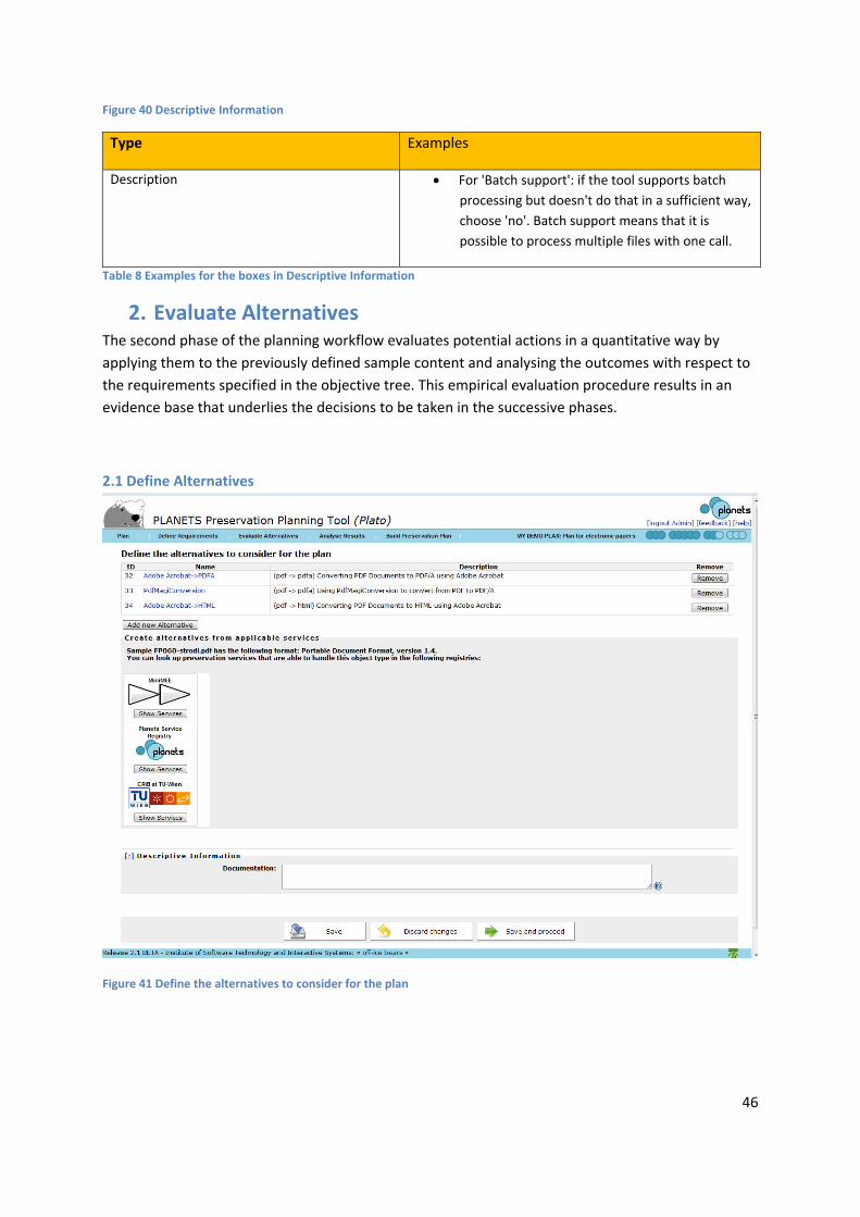
2. Evaluate Alternatives The second phase of the planning workflow evaluates potential actions in a quantitative way by
applying them to the previously defined sample content and analysing the outcomes with respect to
the requirements specified in the objective tree. This empirical evaluation procedure results in an
evidence base that underlies the decisions to be taken in the successive phases.
2.1 Define Alternatives
Figure 41 Define the alternatives to consider for the plan

47
Figure 42 CRIB Service Registry: list of potential alternatives
The MiniMEE registry is a prototype that we have developed to show quality‐aware migration
services. The tools you find there are executed in a controlled environment. When running these,
you will receive detailed information about their processor usage, memory consumption, and other
runtime characteristics. Details are available on the documentation page.
Figure 43 Add new Alternative
The natural first step of evaluation is to define the possible courses of actions to be taken into
consideration. A variety of different strategies might be applicable; for each alternative action, a

48
complete specification of the entailed steps and the configuration of the software tool employed is
desired. The discovery of potential actions that are applicable varies in complexity according to the
type of content. Often, this implies an extensive search phase, investigating which tools are
applicable to the type of objects at hand. Registries holding applicable preservation action tools can
be consulted for reference and are potentially very beneficial to support the search. The outcome is a
shortlist of potential candidates for performing preservation actions, which will be evaluated
empirically during the next steps.
2.2 Go/No‐Go
Figure 44 Take the Go decision
Before continuing with the experimentation procedure, this step reconsiders the situation at hand
and evaluates whether it is feasible and cost‐effective to continue the planning procedure. In cases
where the evaluation is considered infeasible or too expensive, a reduction of candidate tools might
be necessary. In order to proceed to the next workflow step, the user has to take the GO decision.
Type Examples
Reason for Decision All Alternatives seem to be viable solutions,
the necessary tolls are available
Action Needed none
Table 9 Examples for the boxes in Take the Go decision

49
2.2.1 Take the go decision
2.3 Develop Experiments
Figure 45 Develop Experiments
This step defines and documents the configuration of the tools on which experiments are carried out,
and thus builds the basis for experiment execution in the next step. This includes setup procedures, a
documentation of the hard‐ and software environment, and additional steps needed to carry through
the evaluation of experiments.
Type: Alternative Examples for Description
Alternative: Adobe Acrobat ‐> DOC Standard Settings of Adobe Acrobat,
Windows XP Workstation with Service Pack 3
used for migration
Install current version of ImageMagick on

50
the Linux (Ubuntu 8.10) machine. Most
current version of ImageMagick package
available is ImageMagick 6.3.7 06/04/09
Q16. Once the package is installed we use
'convert' to convert from GIF to JPEG.
Alternative: Doc‐> DOC Standard Settings of Convert Doc, Windows
XP Workstation with Service Pack 3 used for
migration
Alternative: Acrobat ‐> HTML Standard Settings of Adobe Acrobat,
Windows XP Workstation with Service Pack 3
used for migration
Table 10 Examples for Develop Experiments
2.4 Run Experiments
Figure 46 Run Experiments
In this step, all considered candidate tools for preservation actions are applied to the complete set of
sample objects that have been defined in the first phase. This produces a series of experiment results
that can be analysed and are stored for future evidence. In the case of object conversion, this means
that the resulting output files shall be stored for further reference. When evaluating emulators, a
documentation detailing the experience of rendering of the object is needed.

51
Type: Alternative Examples for Description
Alternative: GraphicsMagick – TIFF to JP2 Standard Settings of Adobe Acrobat,
Windows XP Workstation with Service Pack 3
used for migration
‐compress lossless
–quality 100
Alternative: GeoJasper – TIFF to JP2 GeoJasper 1.3.1. GeoJasper is a Geo
supporting transcoder based on enhanced
jasper library (i.e., it converts image data
from one format to another) correctly
transferring geo information between
GeoTiff and GeoJP2(tm).
geojasper ‐‐verbose ‐f <input file> ‐F <output
file> ‐T jp2
Table 11 Examples for the boxes in Run Experiments
2.4.1 Results Files
Figure 47 Result Files

52
2.5 Evaluate Experiments
Figure 48 Evaluate Experiment
The evaluation of experiments is based on the requirements specified in the objective tree. All
criteria on the leaf level of the objective tree are evaluated, taking into account the empirical
evidence resulting from the experiments conducted.
The initial view of this page provides you with
an objective tree on the upper left,
a matrix of sample objects and experiment results on the lower left,
and an empty space saying "No leaves selected" on the top right,
as shown below.
The task of this page is to provide all evaluation values for every criterion that you have defined in
the tree.
This means both experimental outcomes judging migration quality or the performance of an
emulator, as well certain characteristics of the tool, the process, etc... Some of these evaluation
values might be provided by automated measurement tools; we are working on increasing the
percentage of these. However, currently you still have to enter many of them manually.
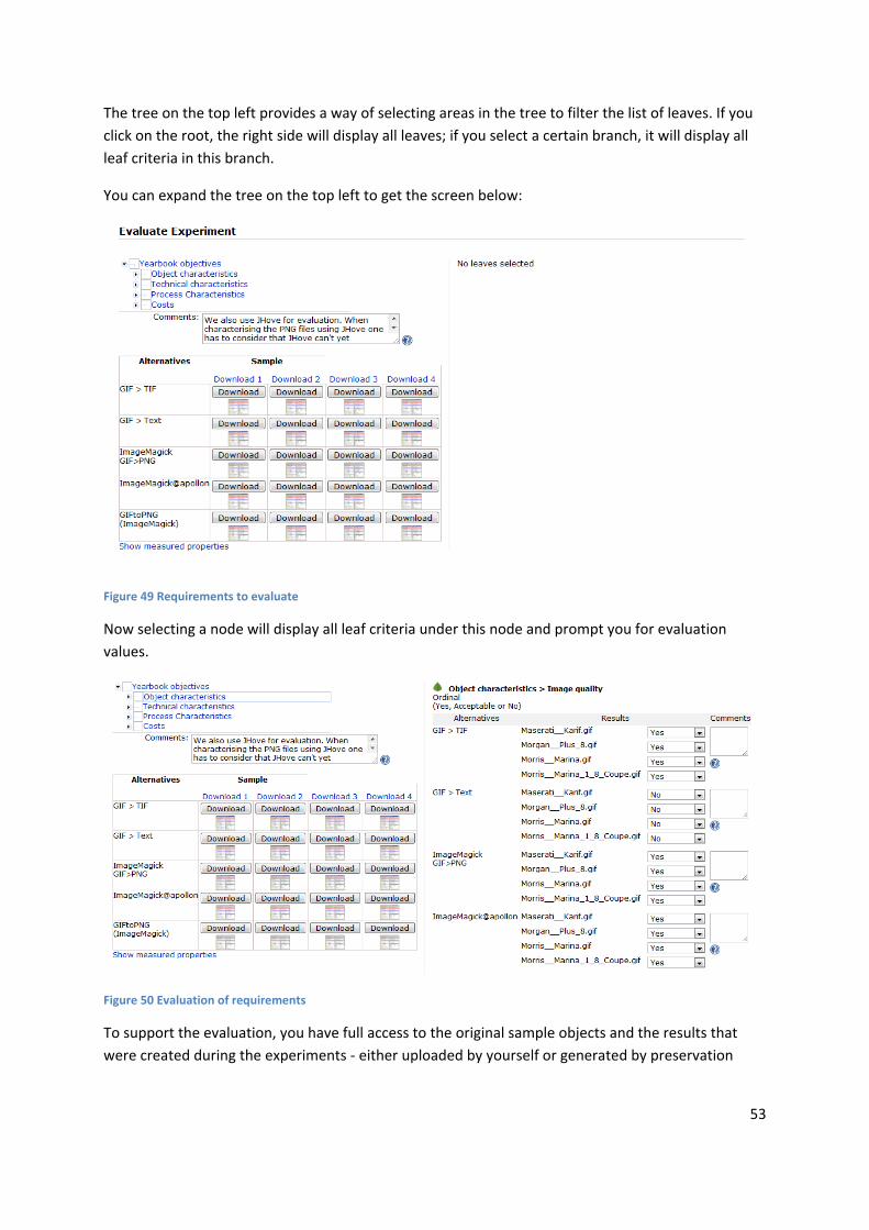
53
The tree on the top left provides a way of selecting areas in the tree to filter the list of leaves. If you
click on the root, the right side will display all leaves; if you select a certain branch, it will display all
leaf criteria in this branch.
You can expand the tree on the top left to get the screen below:
Figure 49 Requirements to evaluate
Now selecting a node will display all leaf criteria under this node and prompt you for evaluation
values.
Figure 50 Evaluation of requirements
To support the evaluation, you have full access to the original sample objects and the results that
were created during the experiments ‐ either uploaded by yourself or generated by preservation

54
actions. You can download the original samples on the top of the table and each result file in the
corresponding cell of the matrix.
You can further get visual support for judging the quality of migration actions by comparing the
charateristics of input and output files extracted by Jhove. Clicking on the matrix in the lower left will
bring up a screen that shows the characteristics of original and converted objects side by side, as
shown below.
Figure 4 Jhove comparing original and converted objects
For reasons of traceability and auditing, Plato checks that each evaluation field has actually been
entered. So you have to either manually specify a value for each field or confirm the evaluation data
by clicking Approve all values before you can proceed to the next step.

55
3. Analyse Results
3.1 Transform Measured Values
Figure 51 Transform Measured Values
The result of the previous step is an objective tree fully populated with evaluation values for all
criteria. However, the measurements in this tree are of varying scales and thus cannot be aggregated
and compared directly. Thus, transformation rules are defined which result in a mapping from all
possible measurement scales to a uniform target scale. This scale usually consists of real numbers
ranging from 0 to 5. The lowest value 0 denotes an unacceptable result, while 5 is the best possible
evaluation value. Corresponding to the scales employed, we can distinguish two types of
transformation settings: numerical thresholds and ordinal mappings.
For ordinal values, a mapping is defined for each possible category, resulting in a value
between 0 and 5 to be assigned. For a boolean scale, Yes might be mapped to 5, whereas No
will often be mapped to a low value. In this case, a decision has to be made whether the
negative result No should be acceptable or not, i.e. mapped to 1 or to 0.
For numeric values, thresholds are defined for each integer number from 1 to 5. All numbers
below the lowest threshold (or above the highest, in case of descending order) will then be
transformed to 0. The calculation of values between the threshold is usually done using
linear interpolation.
In both cases, the definition of acceptance criteria is an essential step, where decision makers have
to clearly specify the constraints they are willing to accept. This further provides a gap analysis which

56
clearly points out both strengths and limitations of the candidates under evaluation.
Figure 52 Transformation tables for different requirements
3.1.1 Why Transformation?
Values in the requirements tree are measured in different units (seconds, euro, bits and goodness values). To be able to aggregate the different values they have to be transformed to a uniform scale. Experience has shown that a scale with the resolution of discrete values 0‐5 with 0 being an unacceptable value and 5 the best possible result works very well.
3.1.2 Transformation tables
For every leaf in the tree a transformation table has to be created:
Ordinal Values, Yes/Acceptable/No For every ordinal or Yes/Acceptable/No value a numeric value has to be assigned. For an ordinal value that is considered better a higher numeric value has to be assigned than to an ordinal value that is considered worse. For an ordinal value that makes an alternative completely unacceptable '0'.
Figure 53 Transformation tables for ordinal scale

57
Numeric Values (Positive Number, Positive Integer, Int Range) For threshold values numeric values are assigned. By selecting the appropriate 'Threshold stepping' it can be chosen, if the transformation should be linear (interpolating between the values) or if steps should be used.
Figure 54 Transformation table for numeric scale
With "Steps" selected for Threshold Stepping, a measured value of e.g. 65 would get the same
transformed value as 60 ('3'). If you choose "Linear" the value will be interpolated between the
transformation values, so a value of '3,5' would be assigned.
Figure 55 Interpolation of measured values
The measured values from the evaluation are shown next to the transformation tables. To help you select the correct numeric values for the transformation, all the measured results are shown in a table to the right of the transformation table. For every alternative the sample records (numbered one to number of sample records) are shown in one line.
Figure 56 Aggregation mode for transformation

58
3.1.3 Examples for transformations for ordinal values and numeric values
Transformation of ordinal values
The following example shows several format characteristics and how each possible value is mapped
onto the utility scale.
Figure 57 Ordinal transformation examples
Transformation of numeric values
This example shows how many MegaBytes per second an alternative is able to handle. The measured
values are again shown next to the transformation table. '0.05' MByte/second is our best result, so
we assigned '5' to this value. '0.01' was the worst result, so '1' is assigned. The other values are
evenly distributed between these values.
'Steps' is selected for Threshold stepping, so if an alternative would be able to handle 0.019
MByte/second, the resulting value would still be '1'.
As aggregation method "Arithmetic Mean" has been selected. If we would have two sample records,
0.01 MByte/second for one of the records and 0.02 MByte/second for the other record the resulting
transformed value would be the arithmetic mean of '1' and '2' ‐> '1.5'.

59
Figure 58 Transformation of numeric values
3.2 Set Importance Factors
This section explains the automatic weight balancing of objective trees in Plato.
Figure 59 Set Importance Factors
When you reach this step the first time, Plato will automatically balance the relative importance of all
nodes in the tree equally. Using the tree table editor, you can then set the relative importance
factors of all siblings in a branch for all levels. The sum of weights on each level must always be equal
to 1; this will be validated before you can proceed.
The column 'total weight' provides the overall influence of a node on the root value. For example, a
node with weight 0.5 that is child of a node with weight 0,5 which is directly under the root will have
a total weight of 0.5*0.5=0.25.
Automatic balancing
If the flag 'Balance weights automatically' is checked, Plato will activate an automatic balancing that
relieves you of checking the sum yourself. Just use the sliders to increase weights of nodes that you
deem important. The remaining weights will be balanced automatically. Each weight becomes locked
once you adjusted it yourself, so that it is not rebalanced afterwards. This is indicated by the 'lock'
column.

60
Example
1. Assume you have a root node with four nodes ‐ A,B,C,D. When you reach the page, all
weights are set to 0.25.
2. Now you adjust the weight of node A to 0.4 ‐ the remaining weights are set to 0.2 each and
node A is locked.
3. Now you adjust the weight of node D to 0.4. The effect is that node D becomes locked, too,
while B and C are set to 0.1 each. Node A is not affected, because it is already locked.
Figure 60 Set Importance Factors
3.3 Analyse evaluation results The final step of the evaluation phase considers the complete evidence base of information produced
during the previous phases of the workflow and analyses the performance of the candidate
components in the experiment evaluation to arrive at a conclusion and recommendation for the best
tool to employed, and the corresponding configuration. Alternatives are ranked by their evaluation
values which are aggregated over the tree hierarchy using two different methods.
Weighted multiplication is used to filter alternatives which exhibit unacceptable evaluation
values at the criterion level, as these have been mapped to a target value of 0 during
transformation and thus result in a total performance of 0.
On the remaining alternatives, weighted addition is used to directly compare the
performance of tools on all levels of the tree hierarchy.
The analysis and comparison of the alternatives considered can be guided significantly by a graphical
visualization as provided by the planning tool described in Section 6. As a result of the evaluation, the
preservation planner makes a decision and recommendation for a tool to be selected. The method
allows for the selection of multiple components that are considered to be complementary. For
example, many conversion tools for electronic documents have problems with entirely preserving
the layout as it was displayed in the original environment, whereas migrating a document to an
image loses the future potential for full‐text search access. In some cases it might be desirable to
combine both approaches and thus select multiple tools for the incorporation into a preservation

61
system. As an essential element of the recommendation, the reasons underlying it are documented,
together with the expected effects of applying this strategy on the set of objects at hand. For
example, it may be known that the easy editability of objects will be lost as a direct cause of
converting them to a format such as PDF/A. As this might not be a requirement, or not be assigned
significant weight, it might not influence the decision in a significant way. However this reasoning
needs to be documented as part of the decision making procedure.
Figure 61 Analyse evaluation results for Preservation Plan for Papers
The change logs stored with the preservation plan can be displayed by clicking on ‘Display
Chang’logs'. The change logs are displayed next to the respective fields or group of fields that have
been altered.
Figure 62 Details for Changelogs
4. Build Preservation Plan In the fourth and final phase of the planning workflow, a preservation plan is created, based on the
decision for a preservation action. It specifies a series of concrete steps or actions, along with
organisational responsibilities, rules and conditions for executing the preservation action on the
collection.
A preservation plan defines a series of preservation actions to be taken by a responsible institution
due to an identified risk for a given set of digital objects or records (called collection). The
Preservation Plan takes into account the preservation policies, legal obligations, organizational and

62
technical constraints, user requirements and preservation goals and describes the preservation
context, the evaluated preservation strategies and the resulting decision for one strategy, including
the reasoning for the decision. It also specifies a series of steps or actions (called preservation action
plan) along with responsibilities and rules and conditions for execution on the collection. Provided
that the actions and their deployment as well as the technical environment allow it, this action plan is
an executable workflow definition.
4.1 Create Executable Plan
Figure 63 Create Executable Plan
This step of the workflow defines the triggers for the execution and the conditions under which the
preservation action will be carried out. Hard‐ and software requirements as well as dependencies to
other systems are documented. To enable the execution of the preservation plan, tool settings and
details about the location of the collection on which the action is to be performed are defined. To
quality assure the performed actions, a subset of the criteria used for evaluating solutions can be
selected. These criteria will then be extracted using characterisation services on the objects after the
performed action and validating that defined thresholds of these criteria are met. The necessary
documentation that has to be recorded for performing the action is also defined in this step.
4.1.1 When
Triggers and conditions for execution Hard‐and software requirements, other dependencies
Type Examples
Triggers and conditions We start to migrate our collection beginning of
November this year.
Validate and QA We use compare functions of ImageMagick and
GraphicsMagick to validate the migrated files. We
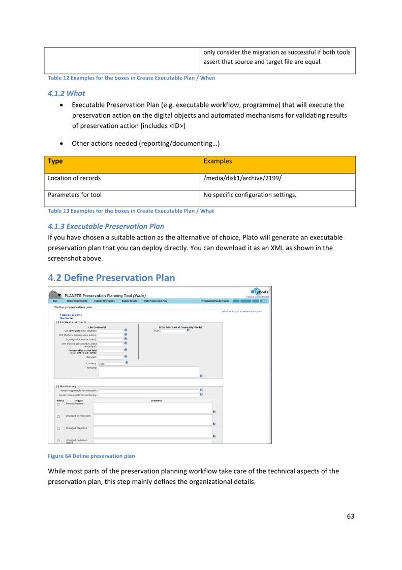
63
only consider the migration as successful if both tools
assert that source and target file are equal.
Table 12 Examples for the boxes in Create Executable Plan / When
4.1.2 What
Executable Preservation Plan (e.g. executable workflow, programme) that will execute the
preservation action on the digital objects and automated mechanisms for validating results
of preservation action [includes <ID>]
Other actions needed (reporting/documenting…)
Type Examples
Location of records /media/disk1/archive/2199/
Parameters for tool No specific configuration settings.
Table 13 Examples for the boxes in Create Executable Plan / What
4.1.3 Executable Preservation Plan
If you have chosen a suitable action as the alternative of choice, Plato will generate an executable
preservation plan that you can deploy directly. You can download it as an XML as shown in the
screenshot above.
4.2 Define Preservation Plan
Figure 64 Define preservation plan
While most parts of the preservation planning workflow take care of the technical aspects of the
preservation plan, this step mainly defines the organizational details.

64
Cost factors influence the decision on a specific alternative. In this step, a more detailed calculation
of costs using an approved cost model is performed. Cost models that can be used are for example
Life2 or the Total Cost of Ownership (TCO) model. While an estimate of the costs may be fine for
evaluating the alternatives, the costs have to be determined as accurate as possible in this step.
The assignment of responsibilities is also documented in this step. Monitoring the process of applying
the preservation actions has to be done by a different role than executing the preservation plan. It
also has to be monitored if an event occurs that makes it necessary to reevaluate the plan. Possible
triggers for this are either a scheduled periodic review, changes in environment such as new available
tools detected through technology watch, changed objectives (changed target community
requirements) or a changed collection profile (e.g. new objects in the collection). Another possible
trigger is that certain thresholds on the evaluation are no longer met by applying the preservation
action.
4.3 Validate Preservation Plan
Figure 65 Validate plan
In the final stage the whole documentation about the preservation plan has to be reviewed. The
process of evaluating different alternatives and taking a decision for a recommended tool based on
the evaluation and the creation of the preservation action plan, the documentation about the basic
framework of the institution and parameters under which the plan is valid are verified again.
The validated plan has to be approved by the person responsible for approval. Once the plan is
approved, no more changes on the plan can be done without revising the whole plan.