pl ver03 - diagramasde.comdiagramasde.com/diagramas/otros2/field servis minolta 550.pdfexposure lamp...
TRANSCRIPT

Di450/Di550
SERVICE MANUAL
[FIELD SERVICE]

P-1
Safety Precautions for Inspection and Service
When performing inspection and service procedures, observe the following precautions toprevent accidents and ensure utmost safety.
✽ Depending on the model, some of the precautions given in the following do not apply.
Different markings are used to denote specific meanings as detailed below.
Indicates a potentially hazardous situation which, if not avoided,could result in death or serious injury.
Indicates a potentially hazardous situation which, if not avoided,may result in minor or moderate injury. It may also be used toalert against unsafe practices.
The following graphic symbols are used to give instructions that need to be observed.
Used to call the service technician’s attention to what is graphically representedinside the marking (including a warning).
Used to prohibit the service technician’s from doing what is graphically repre-sented inside the marking.
Used to instruct the service technician’s to do what is graphically representedinside the marking.
1. Always observe precautions.
2. Before starting the procedures, be sure to unplug the power cord.
3. Use the specified parts.
WARNING
CAUTION
WARNING
• Parts requiring special attention in this product will include a label containing themark shown on the left plus precautionary notes. Be sure to observe the pre-cautions.
• Be sure to observe the “Safety Information” given in the Operator’s Manual.
• This product contains a high-voltage unit and a circuit with a large currentcapacity that may cause an electric shock or burn.
• The product also contains parts that can jerk suddenly and cause injury.• If this product uses a laser, laser beam leakage may cause eye damage or
blindness.
• For replacement parts, always use the genuine parts specified in the manufac-turer’s parts manual. Installing a wrong or unauthorized part could causedielectric breakdown, overload, or undermine safety devices resulting in possi-ble electric shock or fire.
• Replace a blown electrical fuse or thermal fuse with its corresponding genuinepart specified in the manufacturer’s parts manual. Installing a fuse of a differentmake or rating could lead to a possible fire. If a thermal fuse blows frequently,the temperature control system may have a problem and action must be takento eliminate the cause of the problem.

P-2
4. Handle the power cord with care and never use a multiple outlet.
5. Be careful with the high-voltage parts.
6. Do not work with wet hands.
7. Do not touch a high-temperature part.
8. Maintain a grounded connection at all times. (This item may not apply in the USA.)
9. Do not remodel the product.
10. Restore all parts and harnesses to their original positions.
• Do not break, crush or otherwise damage the power cord. Placing a heavyobject on the power cord, or pulling or bending it may damage it, resulting in apossible fire or electric shock.
• Do not use a multiple outlet to which any other appliance or machine is con-nected.
• Be sure the power outlet meets or exceeds the specified capacity.
• A part marked with the symbol shown on the left carries a high voltage. Touch-ing it could result in an electric shock or burn. Be sure to unplug the power cordbefore servicing this part or the parts near it.
• Do not unplug or plug in the power cord, or perform any kind of service orinspection with wet hands. Doing so could result in an electric shock.
• A part marked with the symbol shown on the left and other parts such as theexposure lamp and fusing roller can be very hot while the machine is energized.Touching them may result in a burn.
• Wait until these parts have cooled down before replacing them or any surround-ing parts.
• Be sure to connect the ground wire to the ground terminal even when perform-ing an inspection or repair. Without proper grounding, electrical leakage couldresult in an electric shock or fire.
• Never connect the ground wire to a gas pipe, water pipe, telephone ground wire,or a lightning conductor.
• Modifying this product in a manner not authorized by the manufacturer mayresult in a fire or electric shock. If this product uses a laser, laser beam leakagemay cause eye damage or blindness.
• To promote safety and prevent product damage, make sure the harnesses arereturned to their original positions and properly secured in their clamps and sad-dles in order to avoid hot parts, high-voltage parts, sharp edges, or beingcrushed.
• To promote safety, make sure that all tubing and other insulating materials arereturned to their original positions. Make sure that floating components mountedon the circuit boards are at their correct distance and position off the boards.

P-3
1. Precautions for Service Jobs
2. Precautions for Servicing with Covers and Parts Removed
3. Precautions for the Working Environment
4. Precautions for Handling Batteries
CAUTION
• A toothed washer and spring washer, if used originally, must be reinstalled.Omitting them may result in contact failure which could cause an electric shockor fire.
• When reassembling parts, make sure that the correct screws (size, type) areused in the correct places. Using the wrong screw could lead to strippedthreads, poorly secured parts, poor insulating or grounding, and result in a mal-function, electric shock or injury.
• Take great care to avoid personal injury from possible burrs and sharp edges onthe parts, frames and chassis of the product.
• When moving the product or removing an option, use care not to injure yourback or allow your hands to be caught in mechanisms.
• Wherever feasible, keep all parts and covers mounted when energizing theproduct.
• If energizing the product with a cover removed is absolutely unavoidable, do nottouch any exposed live parts and use care not to allow your clothing to becaught in the moving parts. Never leave a product in this condition unattended.
• Never place disassembled parts or a container of liquid on the product. Partsfalling into, or the liquid spilling inside, the mechanism could result in an electricshock or fire.
• Never use a flammable spray near the product. This could result in a fire.• Make sure the power cord is unplugged before removing or installing circuit
boards or plugging in or unplugging connectors.• Always use the interlock switch actuating jig to actuate an interlock switch when
a cover is opened or removed. The use of folded paper or some other objectmay damage the interlock switch mechanism, possibly resulting in an electricshock, injury or blindness.
• The product must be placed on a flat, level surface that is stable and secure.• Never place this product or its parts on an unsteady or tilting workbench when
servicing.• Provide good ventilation at regular intervals if a service job must be done in a
confined space for a long period of time.• Avoid dusty locations and places exposed to oil or steam.• Avoid working positions that may block the ventilation ports of the product.
• Replace a rundown battery with the same type as specified in the manufac-turer’s parts manual.
• Before installing a new battery, make sure of the correct polarity of the installa-tion or the battery could burst.
• Dispose of used batteries according to the local regulations. Never dispose ofthem at the user’s premises or attempt to try to discharge one.

P-4
5. Precautions for the Laser Beam (Only for Products Employing a Laser)• Removing the cover marked with the following caution label could lead to possi-
ble exposure to the laser beam, resulting in eye damage or blindness. Be sureto unplug the power cord before removing this cover.
• If removing this cover while the power is ON is unavoidable, be sure to wear pro-tective laser goggles that meet specifications.
• Make sure that no one enters the room when the machine is in this condition.• When handling the laser unit, observe the “Precautions for Handling Laser
Equipment.”
DANGERInvisible laser radiation when open.
AVOID DIRECT EXPOSURETO BEAM
0947-7127-01
1144D270AA
1167P001AA

P-5
• To reassemble the product, reverse the order of disassembly unless otherwise specified.• While the product is energized, do not unplug or plug connectors into the circuit boards
or harnesses.• The magnet roller generates a strong magnetic field. Do not bring it near a watch, floppy
disk, magnetic card, or CRT tube.• An air gun and vacuum cleaner generates a strong electrostatic charge that can destroy
the ATDC sensor and other sensors. Before cleaning a component with one of thesedevices, be sure to remove all the sensors. Otherwise, use a blower brush and clothwhen cleaning parts.
• When handling circuit boards with MOS ICs, observe the “INSTRUCTIONS FOR HAN-DLING THE PWBs WITH MOS ICs” (applicable only to the products using MOS ICs).
• The PC Drum is a very delicate component. Observe the precautions given in “HAN-DLING OF THE PC DRUM” because mishandling may result in serious image problems.
• Note that replacement of a circuit board may call for readjustments or resetting of partic-ular items, or software installation.
• After completing a service job, perform a safety check. Make sure that all parts, wiringand screws are returned to their original positions.
• Check the area surrounding the service site for any signs of damage, wear or need ofrepair.
• Do not pull out the toner hopper while the toner bottle is turning. This could result in adamaged hopper motor or locking mechanism.
• If the product is to be run with the front door open, make sure that the toner hopper is inthe locked position.
Other Precautions

P-6
ALL AreasCAUTION
Danger of explosion if battery is incorrectly replaced.Replace only with the same or equivalent type recommended by the manufacturer.Dispose of used batteries according to the manufacturer’s instructions.
GermanyVORSICHT!
Explosionsgefahr bei unsachgemäßem Austausch der Batterie.Ersatz nur durch denselben oder einen vom Hersteller empfohlenen ähnlichen Typ.Entsorgung gebrauchter Batterien nach Angaben des Herstellers.
FranceATTENTION
Ily a danger d’explosion s’ily a remplacement incorrec de la batterie.Remplacer uniquement avec une batterie du meme type ou d’un type équivalent recom-mande par le constructueur.Mettre au rebut les batteries usageés conformément aux instructions du fabricant.
DenmarkADVARSEL!
Lithiumbatteri - Eksplosionsfare ved fejlagtig håndtering Udskiftning må kun ske med bat-teri af samme fabrikat og type.Levér det brugte batteri tilbage til leverandøren.
NorwayADVARSEL
Eksplosjonsfare ved feilaktig skifte av batteri.Benytt samme batteritype eller en tilsvarende type anbefalt av apparatfabrikanten.Brukte batterier kasseres i henhold til fabrikantens instruksjoner.
SwedenVARNING
Explosionsfara vid felaktigt batteribyte.Använd samma batterityp eller en ekvivalent typ som rekommenderas av apparat-tillverkaren.Kassera använt batteri enligt fabrikantens instruktion.
FinlandVAROlTUS
Paristo voi räjähtää, los se on virheellisesti asennettu.Vaihda paristo ainoastaan laitevalmistajan suosittelemaan tyyppiin. Hävitä Käytetty paristovalmistajan ohjeiden mukaisesti.
Used Batteries Precautions

PS-1
PRECAUTIONS FOR SERVICE
When performing inspection and service procedures, observe the following precautions toprevent mishandling of the machine and its parts.✽ Depending on the model, some of the precautions given in the following do not apply.
• When the user is using a word processor or personal computer from a wall outlet of thesame line, take necessary steps to prevent the circuit breaker from opening due to over-loads.
• Never disturb the LAN by breaking or making a network connection, altering termination,installing or removing networking hardware or software, or shutting down networkeddevices without the knowledge and express permission of the network administrator orthe shop supervisor.
1. DIS/REASSEMBLY, ADJUSTMENT• To reassemble the product, reverse the order of disassembly unless otherwise specified.2. TROUBLESHOOTING• If a component on a PWB or any other functional unit including a motor is defective, the
text only instructs you to replace the whole PWB or functional unit and does not give trou-bleshooting procedures applicable within the defective unit.
• All troubleshooting procedures contained herein assume that there are no breaks in theharnesses and cords and all connectors are plugged into the right positions.
• The procedures preclude possible malfunctions due to noise and other external causes.
• Check the area surrounding the service site for any signs of damage, wear or need ofrepair.
• Keep all disassembled parts in good order and keep tools under control so that none willbe lost or damaged.
• After completing a service job, perform a safety check. Make sure that all parts, wiringand screws are returned to their original positions.
• Do not pull out the toner hopper while the toner bottle is turning. This could result in adamaged motor or locking mechanism.
• If the product is to be run with the front door open, make sure that the toner hopper is inthe locked position.
• Do not use an air gun or vacuum cleaner for cleaning the ATDC Sensor and other sen-sors, as they can cause electrostatic destruction. Use a blower brush and cloth. If a unitcontaining these sensors is to be cleaned, first remove the sensors from the unit.
Precautions Before Service
How to Use this Book
Precautions for Service

PS-2
• Be sure to unplug the copier from the outlet before attempting to service the copier.• The basic rule is not to operate the copier anytime during disassembly. If it is absolutely
necessary to run the copier with its covers removed, use care not to allow your clothing tobe caught in revolving parts such as the timing belt and gears.
• Before attempting to replace parts and unplug connectors, make sure that the powercord of the copier has been unplugged from the wall outlet.
• Be sure to use the Interlock Switch Actuating Jig whenever it is necessary to actuate theInterlock Switch with the covers left open or removed.
• Do not plug in or unplug print jacks on the PWB or connect or disconnect the PWB con-nectors while power is being supplied to the copier.
• Never use flammable sprays near the copier.• A battery (lithium, nickel-cadmium, etc.) is used in this machine. Do not charge or short
circuit it and make sure of the correct polarity at replacement.• A used battery should be disposed of according to the local regulations and never be dis-
carded casually or left unattended at the user's premises.• When reassembling parts, make sure that the correct screws (size, type) and toothed
washer are used in the correct places.• If it becomes necessary to replace the thermal fuse or any other fuse mounted on a
board, be sure to use one of the rating marked on the blown fuse. Always note the ratingmarked on the fuse, as the rating and mounting site or number used are subject tochange without notice.
• Never create a closed circuit across connector pins except those specified in the text andon the printed circuit.
• When creating a closed circuit and measuring a voltage across connector pins specifiedin the text, be sure to use the GND wire.
Precautions for Dis/Reassembly
Precautions for Circuit Inspection

PS-3
1. During Transportation/Storage:• During transportation or when in storage, new P.W. Boards must not be indiscriminately
removed from their protective conductive bags.• Do not store or place P.W. Boards in a location exposed to direct sunlight and high tem-
perature.• When it becomes absolutely necessary to remove a Board from its conductive bag or
case, always place it on its conductive mat in an area as free as possible from static elec-tricity.
• Do not touch the pins of the ICs with your bare hands.• Protect the PWBs from any external force so that they are not bent or damaged.
2. During Inspection/Replacement:• Avoid checking the IC directly with a multimeter; use connectors on the Board.• Never create a closed circuit across IC pins with a metal tool.• Before unplugging connectors from the P.W. Boards, make sure that the power cord has
been unplugged from the outlet.• When removing a Board from its conductive bag or conductive case, do not touch the
pins of the ICs or the printed pattern. Place it in position by holding only the edges of theBoard.
• When touching the PWB, wear a wrist strap and connect its cord to a securely groundedplace whenever possible. If you cannot wear a wrist strap, touch a metal part to dis-charge static electricity before touching the PWB.
• Note that replacement of a PWB may call for readjustments or resetting of particularitems.
• The magnet roller generates a strong magnetic field. Do not bring it near a watch, floppydisk, magnetic card, or CRT tube.
Handling of PWBs
Handling of Other Parts

PS-4
✽ Only for Products Not Employing an Imaging Cartridge.1. During Transportation/Storage:• Use the specified carton whenever moving or storing the PC Drum.• The storage temperature is in the range between –20°C and +40°C.• In summer, avoid leaving the PC Drum in a car for a long time.
2. Handling:• Ensure that the correct PC Drum is used.• Whenever the PC Drum has been removed from the copier, store it in its carton or protect
it with a Drum Cloth.• The PC Drum exhibits greatest light fatigue after being exposed to strong light over an
extended period of time. Never, therefore, expose it to direct sunlight.• Use care not to contaminate the surface of the PC Drum with oil-base solvent, finger-
prints, and other foreign matter.• Do not scratch the surface of the PC Drum.• Do not apply chemicals to the surface of the PC Drum.• Do not attempt to wipe clean the surface of the PC Drum.
If, however, the surface is contaminated with fingerprints, clean it using the following proce-dure.
Handling of the PC Drum
1. Place the PC Drum into one half of its carton.
1076D001
2. Gently wipe the residual toner off the surface of thePC Drum with a dry, Dust-Free Cotton Pad.
A. Turn the PC Drum so that the area of its surface onwhich the line of toner left by the Cleaning Blade ispresent is facing straight up. Wipe the surface inone continuous movement from the rear edge ofthe PC Drum to the front edge and off the surfaceof the PC Drum.
B. Turn the PC Drum slightly and wipe the newlyexposed surface area with a CLEAN face of theDust-Free Cotton Pad. Repeat this procedure untilthe entire surface of the PC Drum has been thor-oughly cleaned.
✽ At this time, always use a CLEAN face of the dryDust-Free Cotton Pad until no toner is evident on theface of the Pad after wiping.
1076D002

PS-5
NOTES• Even when the PC Drum is only locally dirtied, wipe the entire surface.• Do not expose the PC Drum to direct sunlight. Clean it as quickly as possible even under
interior illumination.• If dirt remains after cleaning, repeat the entire procedure from the beginning one more
time.
✽ Only for Products Employing an Imaging Cartridge.1. During Transportation/Storage:• The storage temperature is in the range between –20°C and +40°C (-4°F and +104°F).• In summer, avoid leaving the Imaging Cartridge in a car for a long time.
2. Handling:• Store the Imaging Cartridge in a place that is not exposed to direct sunlight.
3. Precautionary Information on the PC Drum Inside the Imaging Cartridge:• Use care not to contaminate the surface of the PC Drum with oil-base solvent, finger-
prints, and other foreign matter.• Do not scratch the surface of the PC Drum.• Do not attempt to wipe clean the surface of the PC Drum.
3. Soak a small amount of either ethyl alcohol or iso-propyl alcohol into a clean, unused Dust-Free Cot-ton Pad which has been folded over into quarters.Now, wipe the surface of the PC Drum in one con-tinuous movement from its rear edge to its frontedge and off its surface one to two times.
✽ Never move the Pad back and forth.
1076D003
4. Using the SAME face of the Pad, repeat the proce-dure explained in the latter half of step 3 until theentire surface of the PC Drum has been wiped.Always OVERLAP the areas when wiping. Twocomplete turns of the PC Drum would be appropri-ate for cleaning.
1076D004
Handling of the Imaging Cartridge


DIS/REASSEMBLY,ADJUSTMENT


�
��������
�� ����������� ����� ��������������������������������������������������������������������������������
���� ���������������� �������� ���������� �����������������������
���� ���� �������������������������� ������ ������������������
���� ���������� ��������� ��� ����������������������������������������������
��� � !"#�$% !�&' () ���������������������������������������������������������������������������
��� �#'�#*+ � )�)%,'),$�,#'! ���������������������������������������������������������������
��� �%- '�&' ()��������������������������������������������������������������������������������������
�� ����������./���������. �������������������������������������������������������������������������
���� �����0�����0����1�����������2����������������
������������ ���������������������������������������������������������������������������
���� ����������� ������������������������
��������� �����������������������������������������������������������������������������������������3
���� � 4,5#+,6%- $�% �����������������������������������������������������������������������������������7
��� � 4,5#+,6%- �8+%��9"#)) $�%������������������������������������������������������7
��� � 4,5#+,6%- �8&%�,$ $�% ��������������������������������������������������������������7
��� � 4,5#+,6%- �#�$�,"" ' $�% ������������������������������������������������������:
�;� � 4,5#+,6%- �� $�% ������������������������������������������������������������������������
�3� � 4,5#+,6%- �� $�% ����������������������������������������������������������������������;
�<� � 4,5#+,6%- � 5 +,"�$= $�% ���������������������������������������������������������<
�>� � 4,5#+,6%- �8*�,"" ' $�% ��������������������������������������������������������<
�?� � 4,5#+,6%- �8)�$= $�% ����������������������������������������������������������������<
�7� � 4,5#+,6%- "" '� 6%�,,'��@�%/�8"+ @�(�%&-�$= $�%�������������>
��;� ���������� �/��������������������������������������������������������������?
��� � 4,5#+,6%- �#" '�#A � "�,++0�#" '� !�,++#$!�#" '
� "#'#%,'�,++�))9� ���������������������������������������������������������������������������?
��� + #$�$=,6%- �#" '�#A � "�,++#$!�#" '� !�,++ �����������������7
��� + #$�$=,6%- �#" '� "#'#%,'�,++ �������������������������������������������������7
�;� � 4,5#+,6%- �'#( '��6%� "�,%,' �������������������������������������������������:
�3� � 4,5#+,6%- "" '#$!�,( '�'#$)",'%�,++ ') ���������������������������
�<� + #$�$=,6%- "" '�'#$)",'%�,++ ' �����������������������������������������������
�>� + #$�$=,6%- �,( '�'#$)",'%�,++ ' �����������������������������������������������
�?� + #$�$=,6%- � '%�&#+�'#$)",'%�,++ ') ������������������������������������������;
�7� � 4,5#+,6%- �9$&-',$�B�$=�,++ ' �������������������������������������������������;
��:� + #$�$=,6%- "" '�9$&-',$�B�$=�,++ '���������������������������������������<
���� � 4,5#+,6%- �,( '�9$&-',$�B�$=�,++ '���������������������������������������<
���� + #$�$=,6%- �,( '�9$&-',$�B�$=�,++ '���������������������������������������>
���� � 4,5#+,6%- �9$&-',$�B�$=�#" '�8)%� 4,5 ' �������������������������>
��;� � 4,5#+,6%- �'#$)",'%�#" '�8)%� 4,5 ' ��������������������������������>
��3� + #$�$=,6%- �#" '�8)%� 4,5 ' �������������������������������������������������?
��<� ��)#)) 4*+9,6%- �8&%�,$ $�% ���������������������������������������������������������?
��>� ��)#)) 4*+9,6%- �8+%��9"#)) $�% ������������������������������������������������7
��?� + #$�$=,6%- �8+%��9"#))�#" '�#A � "�,++/�#" '� !
�,++ �������������������������������������������������������������������������������������������������
��7� + #$�$=,6%- �8+%��9"#))�#" '� "#'#%,'�,++�))9��������������������
��3� ������������ ������������������������������������������������������������������������������������
��� + #$�$=,6%- �'�=�$#+�+#))#$!����+#)) �����������������������������������

��
��� + #$�$=,6%- ��'',') ������������������������������������������������������������������������
��� + #$�$=,6%- � $)����������������������������������������������������������������������������
�;� + #$�$=,6%- �&#$$ '�#�+)/*8)-�$=)����������������������������������������������
�3� + #$�$=,6%- ���+#)) ��������������������������������������������������������������������
�<� � 4,5#+,6%- �&#$$ ' ����������������������������������������������������������������������
�>� � 4,5#+,6%- �@",)8' �#4" ���������������������������������������������������������;
�?� � 4,5#+,6%- ����+#))�����������������������������������������������������������������3
�7� � 4,5#+,6%- �&#$$ '�'�5 #*+ �������������������������������������������������3
��:� ��$!�$=,6%- �&#$$ '�'�5 #*+ ��������������������������������������������������<
��<� ���������� ��� ����������������������������������������������������������������������������������;�
��� � 4,5 ,6%- � 5 +,"�$= $�% ���������������������������������������������������������;�
��� + #$�$=,6%- � 5 +," '�&#%% '�$=�' 5 $%�,$�+#% ��������������������;;
��� + #$�$=,6%- ���,)�%�,$�$=,++#')����������������������������������������������;;
�;� + #$�$=,6%- �,$ '�$%�)"�++�'#" ��������������������������������������������������;;
�3� � "+#& 4 $%,6%- + #$�$=�+#! ��������������������������������������������������;;
�<� � "+#& 4 $%,6%- � 5 +," ' ����������������������������������������������������������;<
�>� + #$�$=,6%- ���� $),'�,#'! ��������������������������������������������������;>
�?� + #$�$=,6%- ��'84�#" '� "#'#%,'��$= ') ��������������������������;>
�7� � 4,5#+,6%- �,$ '�$%�)"�++� #+ ��������������������������������������������������;>
��:� + #$�$=,6%- �,$ '�$%�)"�++� #+ ��������������������������������������������������;?
���� � 4,5#+,6%- �#�$�'#) �#4" �����������������������������������������������������;?
���� + #$�$=,6%- �#�$�'#) �#4"��+% ' ��������������������������������������������;?
���� � 4,5#+,6%- �B,$ ��+% '���'84-#'= ,',$#� ������������������;7
��;� � 4,5#+,6%- �B,$ ��+% '��4#= �'#$)6 '/�#" '� "#'#%,'
,',$#)� ��������������������������������������������������������������������������������������������;7
��3� � 4,5#+,6%- �,$ ',++ &%�$=�,%%+ ���������������������������������������������;7
��>� ��� ���������������������������/�����
��������������� �������������������������������������������������������������������������3:
��� � 4,5#+,6%- ��'84-#'= ,',$# �����������������������������������������3:
��� + #$�$=,6%- ��'84-#'= ,',$#�,8)�$= ���������������������������3:
��� + #$�$=,6%- ��'84-#'= ,',$#�'�!� )- �����������������������3�
�;� + #$�$=,6%- ,4*�+ &%',! ��������������������������������������������������������3�
�3� � 4,5#+,6%- �4#= �'#$)6 '/�#" '� "#'#%,',',$#) ���������������3�
�<� + #$�$=,6%- �4#= �'#$)6 ',',$#��' ������������������������������������3�
�>� � 4,5#+,6%- �4#= �'#$)6 ',',$#��' ������������������������������������3�
�?� + #$�$=,6%- �#" '� "#'#%,',',$#��' ����������������������������������3�
�7� � 4,5#+,6%- �#" '� "#'#%,',',$#��' ����������������������������������3;
��:� + #$�$=,6%- �4#= �'#$)6 '/�#" '� "#'#%,',',$#)
�,8)�$= ���������������������������������������������������������������������������������������������3;
���� + #$�$=,6%- �' ��4#= �'#$)6 '�8�! �+#% ������������������������������33
��?� � ���� �����������������������������������������������������������������������������������������������3<
��� ��)#)) 4*+9,6%- �8)�$= $�% ���������������������������������������������������������3<
��� � 4,5#+,6%- "" '�8)�$=�#" '� "#'#%,'��$= ') �������������������<�
��� + #$�$=,6%- "" '�8)�$=�#" '� "#'#%,'��$= ') �������������������<�
�;� + #$�$=,6%- �,( '�8)�$=�#" '� "#'#%,'��$= ') �������������������<�
�3� + #$�$=,6%- �$%'#$& �8�! �+#% �����������������������������������������������<�
�<� � 4,5#+,6%- "" '�8)�$=�,++ '�- '4�)%,' �������������������������������<�

���
�>� + #$�$=,6%- "" '�8)�$=�,++ '�- '4�)%,' �������������������������������<�
�?� � 4,5#+,6%- �,( '�8)�$=�,++ '�- '4�)%,' �������������������������������<�
�7� + #$�$=,6%- �,( '�8)�$=�,++ '�- '4�)%,' �������������������������������<�
��:� � 4,5#+,6%- "" '�8)�$=�,++ '�- '4,)%#% ������������������������������<�
���� + #$�$=,6%- "" '�8)�$=�,++ '�- '4,)%#% ������������������������������<�
���� � 4,5#+,6%- � *�,++ '����������������������������������������������������������������<;
���� � 4,5#+,6%- � *�' ))8' �,++ ' ������������������������������������������������<;
��;� � 4,5#+,6%- ��)6 !� 4,5#+�$,*�8)-�$= ������������������������������<3
��3� � 4,5#+,6%- �8)�$= $�%�'�5 ,8"+�$=� #'������������������������������<3
��7� � ������ ��� �������������������������������������������������������������������������������������<3
��� + #$�$=,6%- �8'$,5 '�,++ '0�'#$)",'%�,++ ') ���������������������������<3
�� ��C ���������������������������������������������������������������������������������������������������������<<
���� ��C ������C����������� ����������������������������������������������������<<
���� ��C ��������� ������������ ����������������������������������������������������<>
���� ��C ��������������������������������������������������������������������������������<?
��� ��&',)(�%&- ) ������������������������������������������������������������������������������������<?
��� �!D8)%4 $%,6�',$%�,,'�$% '+,&A�(�%&- ����������������������������������������<7
��;� ��C �����������������������������������������������������������������������������>:
��� �!D8)%4 $%,6%- �8&%�,$�'�5 ��4�$=� +% �������������������������������������>:
��� �!D8)%4 $%,6%- � 5 +,"�$= $�%�'�5 ��4�$=� +% ������������������������>:
��� �!D8)%4 $%,6%- �&#$$ '�,%,'��4�$=� +% �����������������������������������>�
��3� ������������������C �����������������������������������������������������������>�
��� �!D8)%4 $%,6�#$8#+� !�#" '��&A� "�,+ $,�! �����������������������>�
��� �!D8)%4 $%,6�8'$,5 '�,++ '� %'#&%�,$�,+ $,�! ��������������������������>;
��� �!D8)%4 $%,6�@�%/�8"+ @�(�%&-�$=�,+ $,�! ����������������������������������>3
�;� �,)�%�,$�$=,6%- ��'84�#" '� "#'#%,'��$= ')
�� "#'#%,'��$= '�,+ $,�!� ��������������������������������������������������������������><
�3� �!D8)%4 $%,6�8'$,5 '�,8% �(�%&-�$=�,+ $,�! ���������������������������>>
��<� ���������������������������C ������ �����������������>?
��� �&& ))�$=%- � &-�� "��,! ��������������������������������������������������������>?
��� �&& ))�$=%- �!D8)%�,! ���������������������������������������������������������������>?
��>� ��������/�������C �������������������������������������������������������������>7
��� �,8&-�#$ +�!D� �������������������������������������������������������������������������������>7
��� �'�=���B �!D8)% ��������������������������������������������������������������������������������?:
��� �?���� $),' �������������������������������������������������������������������������������?�
�;� �3���� $),' ��������������������������������������������������������������������������������?�
�3� � =�)%'#%�,$��� �������������������������������������������������������������������������������?�
�<� � =�)%'#%�,$���� �������������������������������������������������������������������������������?3
�>� � #!�!= �'#) �������������������������������������������������������������������������������?>
�?� �'#�+�!= �'#) ��������������������������������������������������������������������������������?7
�7� �,,"�!D8)%4 $%��������������������������������������������������������������������������������7�
��:� �'#)8' ��!%- ������������������������������������������������������������������������������������7�
���� E,,4��� �����������������������������������������������������������������������������������������73
���� E,,4���� �����������������������������������������������������������������������������������������7>
���� �&#+ ��� �����������������������������������������������������������������������������������������77
��;� �&#+ ���� ������������������������������������������������������������������������������������������:�
��?� �������C �����������������������������������������������������������������������������������:�

�5
��� �!D8)%4 $%,6%- � 6 ' $& �,)�%�,$,6�#&-�'#( ' ����������������������:�
��� �!D8)%4 $%,6%- � 6 ' $& �,)�%�,$,6%- �8+%��9"#))�'#9���������:3
��� �!D8)%4 $%,6%- "" '��=-%�,,'��8+%��9"#)) $�%� �������������������:<
�;� �!D8)%4 $%,6%- �,)�%�,$,6%- �&#$$ '#$!�$!/�'!��'',')
#''�#= ����������������������������������������������������������������������������������������������:>
�3� �!D8)%4 $%,6%- �$!/�'!��'',')#''�#= �))96,'�#'#++ +
�+�=$4 $%��������������������������������������������������������������������������������������������:?
�<� �!D8)%4 $%,6%- �#"� %( $%- �,&%,'�+#! #$!�+ 5
�,++ '������!D8)%4 $%� ���������������������������������������������������������������������:7
;� ���������� � ����������������������������������������������������������������������������������������������:
;��� �������������������.� ����������������� �����������������:
;��� �� ������������������E������������������������ �����
;��� ����������. �����������������������������������������������������������������������������������������
��� � ('�%�$=%- �#)% '�,#'!�#%# ���������������������������������������������������������
��� � ('�%�$=%- �4#= �',& ))�$=�,#'!�#%#����������������������������������������
��� � ('�%�$=%- ��,#'!�#%#�,"%�,$������������������������������������������������3
�;� � ('�%�$=%- �#)% '�,#'!0�4#= �',& ))�$=�,#'!0#$!�
�,#'!��"%�,$���48+%#$ ,8)+9������������������������������������������������������������<
;�;� ���� ���������� ������������������������������������������������������������������������������>
��� � 4,8$%�$=�����,$%- �#)% '�,#'! �����������������������������������������>
��� � 4,8$%�$=�����,$%- �4#= �',& ))�$=�,#'!������������������������?

D-1
1. SERVICE INSTRUCTIONS1-1. IDENTIFICATION OF FUSES AND CIRCUIT BREAKERS
1-2. PRECAUTIONS FOR HANDLING THE LASER EQUIPMENT• The laser used in this copier is a semiconductor laser having the following specifications.
• When laser protective goggles are to be used, select ones with a lens conforming to theabove specifications.
• When a disassembly job needs to be performed in the laser beam path, such as whenworking around the printerhead and PC Drum, be sure first to turn the copier OFF.
• If the job requires that the copier be left ON, take off your watch and ring and wear laserprotective goggles.
• A highly reflective tool can be dangerous if it is brought into the laser beam path. Useutmost care when handling tools on the user’s premises.
• The printerhead is not maintainable in the field. It is to be replaced as an assemblyincluding the control board. Never, therefore, attempt to remove the laser diode or adjusttrimmers on the control board.
4002M014AB
Inverter BoardINV 250 V 2 A (F1)
Power Supply BoardPWB-C 250 V 4 A (6 pcs.)
DC Power Supply MainPU1 <100 V Areas>
125 V 15 A (F1)125 V 4 A (F2)125 V 15 A (F3)125 V 6.3 A (F4)<200 V Areas>250 V 8 A (F1)250 V 3.15 A (F2)250 V 8 A (F3)250 V 3.15 A (F4)
Upper Fusing Roller ThermostatTS1 250 V 10 A
DC Power Supply SubPU2 <100 V Areas>
125 V 4 A (F1)250 V 3.15 A (F2)<200 V Areas>250 V 3.15 A (F1)250 V 1.60 A (F2)
Max. power: 5 mW × 2Output wavelength: 770 to 800 nm

D-2
NOTES• The Organic Photoconductor Drum is softer than CdS and Selenium Drums and is there-
fore susceptible to scratches.• Even when the PC Drum is only locally dirtied, wipe the entire surface.• Do not expose the PC Drum to direct sunlight. Clean it as quickly as possible even under
interior illumination.• If dirt remains after cleaning, repeat the entire procedure from the beginning one more
time.
1-3. PARTS WHICH MUST NOT BE TOUCHED(1) Red painted Screws
Purpose of Application of Red PaintRed painted screws show that the assembly or unit secured can only be adjusted or set atthe factory and should not be adjusted, set, or removed in the field.Note that when two or more screws are used on the part in questions, only one representa-tive screw may be marked with red paint.
(2) Variable Resistors on Board
Do not turn the variable resistors on boards for which no adjusting instructions are given in“ADJUSTMENT.”
(3) Other Screws
Although not marked with red paint, the following screws must not be loosened or read-justed.
4002D256AA
4 screws on the Image Transfer/Paper Separator Coronas
8 screws on the PH Unit Cover
4002D104AB
2 screws on the SeparatorFinger Solenoid
4002D257AA

D-3
2. DISASSEMBLY/REASSEMBLY2-1. DOORS, COVERS, AND EXTERIOR PARTS: IDENTIFICATION
AND REMOVAL PROCEDURES
4002D025AC
1 2 3
4
5
6
789
10
11
12
13
18
17
1615
14
4002D026AC

D-4
No. Part Name Removal Procedure
1 Original Glass Remove No.3.
2 EDH Glass Remove No.3.
3 EDH Glass Holder Raise No.13. � Remove four EDH Glass Holder mountingscrews.
4 Control Panel Raise No.13. � Swing down No.5. � Remove No.18. � RemoveNo.11. � Remove five Control Panel mounting screws. � Unplugtwo connectors.
5 Front Door Swing down the Front Door. � Remove two Front Door hingeshafts. � Remove two belt mounting screws inside the FrontDoor.
6 1st Drawer Slide out the drawer. � Remove one screw and the right stopper.� Pressing the tab on the left rail, pull out the drawer.7 2nd Drawer
8 Middle Left Door Remove No.11. � Remove two Middle Left Door mountingscrews.
9 Upper Left Door(Exit/DuplexSwitching Unit)
� D-17
10 Filter Cover Unhook one tab on the Filter Cover.
11 Left Cover Slide out No.6. � Swing down No.5. � Remove seven Left Covermounting screws.
12 Rear Upper Cover Remove No.13. � Remove No.11. � Remove No.18. � Removetwo Rear Upper Cover mounting screws.
13 Original Cover Remove the Original Cover by pulling up.
14 Rear Cover Remove nine Rear Cover mounting screws.
15 Connector Cover Remove one Connector Cover mounting screws.
16 Upper Right Door(Multi BypassUnit)
� D-9
17 Counter Cover Unhook two tabs on the Counter Cover.
18 Right Cover Slide out No.6. � Swing down No.5. � Open No.16. � Open theMulti Bypass Table. � Remove seven Right Cover mountingscrews.

D-5
2-2. REMOVAL OF CIRCUIT BOARDS AND OTHER ELECTRICAL
COMPONENTS• When removing a circuit board or other electrical component, refer to “Handling of
PWBs” and follow the corresponding removal procedures.• The removal procedures given in the following omit the removal of connectors and
screws securing the circuit board support or circuit board.• Where it is absolutely necessary to touch the ICs and other electrical components on the
board, be sure to ground your body.
4002M013AC
PWB-ICPWB-A
INV
PWB-B
PWB-IA
UN1
PWB-S
PWB-C
HV1
PU2
PU1
PWB-I2
PWB-I1
UN2
PWB-G
PWB-R

D-6
NOTEPWB-M and PWB-R: optional on both the 45-cpm copier and 55-cpm copier.
Symbol Part Name Removal Procedure
INV Inverter Board Remove the Scanner. � Unplug two connectors andremove two screws and the Inverter Board MountingBracket Assy. � INV
PWB-A Master Board Remove the Right Cover. � Remove the Rear Cover. �
Remove three screws and the Cover. � Remove fourscrews and the Cover. � PWB-A
PWB-B Image ProcessingBoard
� D-7
PWB-C Power SupplyBoard
Remove the Right Cover. � Remove the Rear Cover. �
Remove six screws and the Board Cover. � PWB-C
PWB-G AIDC SensorBoard
� D-41
PWB-I1 Paper SizeDetecting Board 1
Remove four screws and the PC Drum Charge/DevelopingBias HV Mountaing Bracket Assy. � Remove two screwsand the Board Cover. � PWB-IPWB-I2 Paper Size
Detecting Board 2
PWB-IC SCP Board Remove the Rear Upper Cover. � PWB-IC
PWB-M Memory Board Remove the Original Glass. � Remove four screws and theIR Base Plate Left Cover. � PWB-M
PWB-R HDD Power Sup-ply Board
Remove the Rear Cover. � Remove the Left Cover. �
Remove three screws and the HDD Mounting Bracket Assy.� PWB-R
PWB-S Tech. Rep. SettingSwitches Board
Swing down the Front Door. � Remove the Left Cover. �
Remove four screws and the Cover. � PWB-S
UN1 Control Panel Remove the Control Panel Unit. � UN1
UN2 ATDC Sensor � D-41
PU1 DC Power SupplyMain
Remove the Rear Cover. � Remove six screws and theBoard Cover. � PU1
PU2 DC Power SupplySub
Remove the Rear Cover. � Remove the Left Cover. �
Remove three screws and the DC Power Supply SubMounting Bracket Assy. � PU2
HV1 PC Drum Charge/Developing BiasHV
Remove the Rear Cover. � Remove six screws and theBoard Cover. � Remove ten screws and the DC PowerSupply Main Mounting Bracket Assy. � HV1

D-7
Removal of the Image Processing Board
1. Remove the Rear Cover and Right Cover.2. Remove the Original Glass and EDH Glass.3. Remove eight screws and the CCD Unit Cover.
4002D043AB
4. Remove four screws and the cover on the left.5. Remove three screws and the cover on the right.
4002D044AC
6. Remove three screws and the PH Cooling FanMotor mounting bracket Assy.
7. Remove six screws and the mounting bracket.
4002D046AB
8. Remove five screws and the Cover.
4002D238AC
Cover
9. Remove five screws and the Master Board Mount-ing Bracket Assy.
4002D069AC

D-8
10. Unplug two connectors, one flat cable.
4002D034AC
11. Unplug five connectors, two flat cables.12. Remove the harness from the edge cover.
4002D258AB
13. Unplug four connectors.14. Remove five screws and the Imaging Processing
Board Mounting Bracket Assy.
4002D515AA
15. Remove ten screws and the Imaging ProcessingBoard.
4002D516AA

D-9
2-3. Removal of the Unit(1) Removal of the Multi Bypass Unit
(2) Removal of the Suction Unit
1. Swing down the Front Door and slide out the Developer Unit.2. Remove the Paper Dust Remover Assy.3. Slide out the Fusing Unit.4. Slide out the 1st and 2nd Drawers.
1. Open the Upper Right Door.2. Remove two connectors and the cover.3. Unplug two connectors.
4002D027AD
4. Remove two screws and the Upper Right Cover.
NOTEWhen reinstalling the Upper Right Cover, Adjustmentof the Upper Right Door (Multi Bypass Unit).� D-106
4002D028AB
5. Unplug two connectors from lower end of the Suc-tion Unit.
4002D029AA
6. Swing the Transport Section Release Lever back toits original position.
7. Pressing down the Transfer/Paper Separator Coro-nas Unit, pull out of the copier.
4002D030AB

D-10
(3) Removal of the Main Hopper Unit
1. Swing down the Front Door and slide out the Developer Unit.2. Remove the Right Cover.
8. Swing down the Transport Section Release Lever.9. Holding up the Suction Unit, remove the compres-
sion coil.
4002D031AD
10. Remove the Suction Unit by sliding it to the right.
1136D101AA
NOTEWhen reinstalling the Suction Unit, make sure that twopositioning pins on the copier fit into the positioningholes in the Suction Unit.
1134D028AA
3. Unplug two connectors, remove four screws andremove the Main Hopper Unit.
4002D032AD

D-11
(4) Removal of the IR Unit
1. Swing down the Front Door and slide out the Developer Unit.2. Remove the Right Door, Left Door, Rear Upper Cover, Rear Cover and Control Panel.3. Slide out the Fusing Unit.
4. Remove four screws and the Cover.
NOTEDo not remove the belt mounting screw on the cover.
4002D196AC
5. Unplug two connectors, remove four screws andremove the Main Hopper Unit.
4002D032AD
6. Remove three screws and the PH Cooling FanMotor mounting bracket Assy.
7. Remove six screws and the mounting bracket.
4002D046AB
8. Remove the Original Grass and EDH Glass.9. Remove eight screws and the CCD Unit Cover.
4002D043AB
10. Remove four screws and the Cover.
4002D033AB

D-12
11. Unplug two connectors, one flat cable from theImaging Processing Board.
4002D034AC
12. Unplug four connectors at the front.
4002D035AD
13. Remove five screws and the Cover.
4002D238AC
Cover
14. Remove five screws and the Master Board Mount-ing Bracket Assy.
4002D069AC
15. Unplug ten connectors in the rear.16. Remove one screw and the ground wire.
4002D036AC

D-13
17. Remove two screws and the relay connector.
4002D037AB
18. Remove four screws and the right mountingbracket.
4002D038AC
19. Remove four screws and the left mounting bracket.
4002D039AC
20. Remove five screws that secure the IR Unit on thefront side.
4002D040AD
21. Remove four screws that secure the IR Unit in therear.
4002D041AB

D-14
(5) Removal of the PH Unit
NOTES• Do not place the PH Unit upside down, tilt it excessively, or subject it to excessive shock.• Replace the PH Unit as one unit.• NEVER attempt to disassemble or adjust the PH Unit.• Whenever the PH Unit has been removed, make the following adjustments:
Lead/Trail Edge Erase and Registration (CD/FD).
22. Remove the IR Unit.
4002D042AB
1. Remove the Right Cover.2. Remove the Original Glass and EDH Glass.3. Remove eight screws and the CCD Unit Cover.
4002D043AB
4. Remove three screws and the cover.
4002D260AA
5. Unplug two connectors, two flat cables.6. Remove the harness from the edge cover.
4002D045AB

D-15
7. Remove three screws and the PH Cooling FanMotor mounting bracket Assy.
8. Remove six screws and the mounting bracket.
4002D046AB
9. Remove the harness from two cord clamps andone edge cover.
4002D047AC
10. Unplug two relay connectors and remove the har-ness from the cord clamp.
4002D048AB
11. Swing down the Front Door and slide out theDeveloper Unit.
12. Remove two thumbscrews and one bolt.
4002D049AB
13. Remove the PH Unit.
4002D050AB

D-16
(6) Removal of the Developing Unit
(7) Removal of the Sub Hopper Unit
(8) Removal of the Fusing Unit
1. Swing down the Front Door.2. Swing down the Transport Section Release Lever.
4002D051AB
3. Loosen two screws and remove the DevelopingUnit.
4002U072AB
1. Swing down the Front Door and slide out theDeveloping Unit.
2. Unplug one connector and remove three screwsand the Sub Hopper Unit.
4002D053AA
1. Open the Left Door.2. Swing Down the Front Door.3. Remove one screw and slide out the Fusing Unit.
4002D054AC

D-17
(9) Removal of the Upper Left Door (Exit/Duplex Switching Unit)
1. Swing down the Front Cover and slide out the Fus-ing Unit.
2. Remove the cable from the spring.
4002D261AA
3. Remove the Rear Cover.4. Open the Upper Left Door.5. Remove the Left Cover.6. Unplug one connector and remove the harness
from the edge cover.7. Remove one screw, holding bracket, and the band.
4002D055AC
8. Remove one screw and the holding bracket.9. Remove the Upper Left Door.
4002D056AE

D-18
2-4. PAPER TAKE-UP/TRANSPORT SECTION(1) Removal of the Paper Take-Up Roll, Paper Feed Roll and Paper Separator Roll
Assy.
5. Disassemble the Paper Separator Roll Assy.
1. Remove the Right Door.2. Remove one screw and the Paper Guide Plate
from each drawer.
4002D057AB
3. Remove the Paper Separator Roll/Paper GuidePlate Assy. by turning it about 90 in the direction ofthe arrow.
4002D058AC
4. Loosen one screw and remove the Paper Separa-tor Roll Mounting Bracket Assy.
4002D059AE
4002D060AB

D-19
(2) Cleaning of the Paper Take-Up Roll and Paper Feed Roll
(3) Cleaning of the Paper Separator Roll
6. Unbending one tab of the holder, remove theholder.
4002D061AB
7. Remove the Paper Take-Up Roll and Paper FeedRoll.
4002D062AB
1. Remove the Paper Separator Roll MountingBracket Assy.
2. Using a soft cloth dampened with alcohol, wipeeach roll clean of dirt.
4002D063AA
1. Remove the Paper Separator Roll MountingBracket Assy.
2. Using a soft cloth dampened with alcohol, cleanthe Paper Separator Roll.
4640D009AA

D-20
(4) Removal of the Drawer Lift-Up Motor
1. Remove the Right Door.2. Slide out the drawer and remove one screw and
the right stopper.
4002D065AB
3. Pushing the tab on the left rail, pull out the drawer.
4002D066AC
4. Remove three screws and the Drawer Set SensorMounting Bracket Assy.
5. Unplug one connector.
NOTEReinstall the Drawer Set Sensor Mounting Bracket asyou hold the lever.
4002D067AB
6. Unplug two connectors.7. Remove one screw and the Drawer Lift-Up Unit.
NOTEWhen reinstalling the Drawer Lift-Up Unit, make surethat the mounting bracket is properly aligned with thepositioning dowel pin on the copier.
4002D262AA

D-21
8. Disassemble the Drawer Lift-Up Unit.
(5) Removal of the Upper and Lower Transport Rollers
1156D022AA
1. Swing down the Front Door and slide out theDeveloping Unit.
2. Slide out the 1st Drawer.3. Remove the Rear Cover.4. Remove the Right Cover.5. Remove five screws and the Cover.
4002D238AC
Cover
6. Remove five screws and the Master Board Mount-ing Bracket Assy.
4002D069AC
7. Remove six screws and the board cover.
4002D068AC

D-22
8. Remove three screws and the Power Supply BoardMounting Bracket Assy.
4002D070AB
9. Remove three screws and the Flywheel.
4002D071AB
10. Remove three screws and the Transport/Synchro-nizing Rollers Drive Assy.
4002D073AB
11. Snap off the E-ring and remove the gear.12. Unhook one spring and snap off one E-ring. Then
remove the bushing from the rear end of the UpperTransport Roller.
13. Snap off one E-ring and remove the bearing fromthe rear end of the Lower Transport Roller.
4002D239AC
14. Remove three screws and the Cover.
NOTEDo not remove the belt mounting screw on the cover.
4002D075AB

D-23
(6) Cleaning of the Upper Transport Roller
(7) Cleaning of the Lower Transport Roller
15. Unhook one spring and snap off two E-rings. Thenremove the bushings from the front end of theUpper and Lower Transport Roller.
4002D240AB
16. Remove the Upper Transport Roller.17. Remove the Lower Transport Roller.
4002D241AA
1. Swing down the Front Door and slide out theDeveloping Unit.
2. Using a soft cloth dampened with alcohol, cleanthe Upper Transport Roller.
4002D242AA
1. Swing down the Front Door and slide out theDeveloping Unit.
2. Using a soft cloth dampened with alcohol, cleanthe Lower Transport Roller.
4002D243AA

D-24
(8) Cleaning of the Vertical Transport Rollers
(9) Removal of the Synchronizing Roller
1. Open the Upper Right Door.2. Using a soft cloth dampened with alcohol, wipe
each roller clean of dirt.
4002D244AA
1. Swing down the Front Door and slide out theDeveloping Unit.
2. Remove the Rear Cover.3. Remove the Right Cover.4. Remove five screws and the Cover.
4002D238AC
Cover
5. Remove five screws and the Master Board Mount-ing Bracket Assy.
4002D069AC
6. Remove six screws and the board cover.
4002D068AC
7. Remove three screws and the Power Supply BoardMounting Bracket Assy.
4002D070AB

D-25
8. Remove three screws and the Flywheel.
4002D071AB
9. Unplug two connectors and remove five screwsand the Developing Unit Drive Assy.
4002D072AB
10. Unplug two connectors and remove three screwsand the Transport/Synchronizing Rollers DriveAssy.
4002D073AB
11. Snap off the E-ring and remove the gear.12. Snap off one E-ring and remove the bushing from
the rear end of the Upper Synchronizing Roller.
4002D074AA
13. Remove three screws and the Cover.
NOTEDo not remove the belt mounting screw on the cover.
4002D075AB

D-26
(10) Cleaning of the Upper Synchronizing Roller
(11) Removal of the Lower Synchronizing Roller
14. Snap off the E-ring and remove the bushing fromthe front end of the Upper Synchronizing Roller.
15. Remove the Upper Synchronizing Roller.
4002D076AB
1. Swing down the Front Door and slide out theDeveloping Unit.
2. Using a brush or a vacuum cleaner, clean theUpper Synchronizing Roller.
4002D080AB
1. Remove the Suction Unit.2. Unhook the spring, snap off the E-ring, and remove
the bushing from the front end of the Lower Syn-chronizing Roller.
4002D077AC
3. Unhook the spring, snap off the E-ring, and removethe gear and bushing from the rear end of theLower Synchronizing Roller.
4002D078AC
4. Remove the Lower Synchronizing Roller.
4002D079AC

D-27
(12) Cleaning of the Lower Synchronizing Roller
(13) Removal of the Synchronizing Paper Dust Remover
(14) Removal of the Transport Paper Dust Remover
1. Swing down the Transport Section Release Lever.2. Using a brush or a vacuum cleaner, clean the
Lower Synchronizing Roller.
4002D081AB
1. Swing down the Front Door and slide out theDeveloping Unit.
2. Remove one screw and the Synchronizing PaperDust Remover Assy.
4002D082AB
NOTEWhen only the Paper Dust Remover is to be replaced,affix the new one along the reference line as shown onthe left.
1136D094AA
1. Open the Upper Right Door.2. Remove the Transport Paper Dust Remover Assy.
4002D263AA

D-28
(15) Cleaning of the Paper Dust Remover
(16) Disassembly of the Suction Unit
NOTEWhen only the Paper Dust Remover is to be replaced,affix the new one along the reference line as shown onthe left.
4002D517AA1 mm
1. Remove the Synchronizing Paper Dust RemoverAssy.
2. Using a brush, whisk dust off the SynchronizingPaper Dust Remover.
1136D095AA
1. Remove the Transport Paper Dust Remover Assy.2. Using a brush, whisk dust off the Transport Paper
Dust Remover.
4002D541AA
1. Remove the Suction Unit.2. Remove two screws and the duct.3. Remove four screws and the Suction Drive Unit.
NOTEWhen reinstalling the Suction Drive Unit, try to press itdown against the Suction Base Plate.
4002D083AB
4. Remove four driven rolls.
4002D084AB

D-29
(17) Disassembly of the Multi Bypass Unit
5. Remove four Suction Belts.
4002D085AB
6. Remove the Suction Roller as shown on the left.
4002D086AB
1. Remove the Right Door.2. Remove four screws and the Separator Guide
Plate Assy.
4002D087AB
3. Remove the Spring.
NOTEWhen reinstalling the Spring, place it so that its close-coiled end faces the Separator Unit.
4002D088AB
4. Snap off the C-clip and remove the Separator Assy.
4002D089AB

D-30
5. Snap off the C-clip and remove the Separator RollAssy.
1136D109AA
6. Remove five screws and the Solenoid MountingBracket Assy.
NOTEWhenever a solenoid has been replaced or a solenoidmounting screw removed, be sure to adjust the posi-tion of the solenoid.� D-72
4002D090AB
7. Snap off the E-ring and remove the gear.8. Unhook the spring and remove the gear assy.
4002D091AB
9. Snap off the E-ring and remove the Paper Take-UpRoll Assy.
4002D092AB
10. Snap off the E-ring and remove the Paper FeedRoll.
4002D093AB

D-31
(18) Cleaning of the Multi Bypass Paper Take-Up Roll/Paper Feed Roll
(19) Cleaning of the Multi Bypass Paper Separator Roll Assy.
11. Snap off the E-ring and remove the Paper Take-UpRoll.
4002D094AB
1. Using a soft cloth dampened with alcohol, cleanthe Paper Take-Up Roll/Paper Feed Roll.
4002D095AB
1. Using a soft cloth dampened with alcohol, cleanthe Paper Separator Roll Assy.
4002D097AB

D-32
2-5. OPTICAL SECTION(1) Cleaning of the Original Glass and EDH Glass
(2) Cleaning of the Mirrors
(3) Cleaning of the Lens
1. Wipe clean the Original Glass and EDH Glass witha soft cloth.
4002O262AB
1. Remove the Original Glass.2. Wipe the surface of each mirror clean of dirt using
a soft cloth.
4002D107AA
1. Remove the Original Glass and EDH Glass.2. Remove eight screws and the CCD Unit Cover.3. Remove four screws and the Lens Cover.
4002D108AB
4. Wipe clean the Lens with a soft cloth.
4002D109AA

D-33
(4) Cleaning of the Scanner Rails/bushings
(5) Cleaning of the PH Glass
(6) Removal of the Scanner
1. Remove the Original Glass.2. Wipe clean the Scanner Rails/bushings with a soft
cloth.
NOTEApply lubricant to the Scanner Rails/Bushings afterthey have been cleaned.
4002D100AA
1. Swing down the Front Door and slide out theDeveloping Unit.
2. Open the cover.
4002D265AA
3. Wipe clean the PH Glass with a soft cloth.
4002D099AB
1. Remove the Original Glass.2. Slide the Scanner to the position shown.3. Remove the two Scanner mounting screws at the
front and rear.
4002D101AC

D-34
(7) Removal of the Exposure Lamp
NOTEDo not remove the Scanner positioning screws.
4002D264AB
Scanner mounting screws
Scanner positioning screws
4. Swing the Scanner counterclockwise and take itout of the copier.
NOTEAt this point, the Scanner is kept connected to a flatcable and cannot be taken off.
4002D102AB
5. Unplug one connector.6. Remove two screws and the flat cable board.7. Remove the Scanner.
4002D103AB
1. Remove the Scanner.2. Unplug one connector from the Inverter Board.3. Remove the harnesses from the corresponding
wiring saddles.
4002D105AF
4. Remove one screw and the Exposure Lamp.
4002D106AC

D-35
(8) Removal of the EDH Glass
(9) Removal of the Scanner Drive Cable
1. Remove the Original Glass and EDH Glass.2. Remove the Left Cover, Right Cover, Rear Upper Cover and Control Panel.3. Remove the CCD Unit Cover.4. Remove the Scanner.
1. Remove four screws and the EDH Glass Holder.2. Remove the EDH Glass.
4002D245AB
5. Unhook the springs of the Scanner Drive Cableson the hook side, one each at the front and in therear.
6. Remove the front and rear Scanner Drive Cables.
4002D110AB
7. Remove three screws and the Scanner MotorMounting Bracket Assy.
4002D111AC
8. Remove one screw and then slide the front pulleyand bushing toward the rear.
4002D112AA

D-36
(10) Winding of the Scanner Drive Cable
9. Remove one screw and the slide the rear pulleyand bushing toward the front.
4002D113AA
10. Remove the Scanner Drive Gear, pulleys andbushings at the front and rear, and the shaft.
4002D114AD
4002D001AA
Pulley C
Pulley B
Pulley F
Pulley A
Pulley E
Pulley D
1. Position the round bead of the Scanner DriveCable in the pulley as shown.
NOTEMake sure that the bead snugly rests in the slit in thepulley.
Front
4002D002AA
Bead

D-37
2. Wind the fixed bead end of the cable around thepulley five turns clockwise, from the rear toward thefront side.
4002D003AA
3. Wind the hook end of the cable around the pulleyfive turns counterclockwise, from the front towardthe rear side.
NOTEMake sure that no part of the cable rides on the other.
4002D004AA
4. Slip the Cable Holding Jig onto the pulley to securethe cable in position.
4002D501AA
5. Position the round bead of the Scanner DriveCable in the pulley as shown.
NOTEMake sure that the bead snugly rests in the slit in thepulley.
Rear
4002D005AA
Bead
6. Wind the fixed bead end of the cable around thepulley five turns clockwise, from the front towardthe rear side.
4002D006AA

D-38
7. Wind the hook end of the cable around the pulleyfive turns counterclockwise, from the rear towardthe front side.
NOTEMake sure that no part of the cable rides on the other.
4002D007AA
8. Slip the Cable Holding Jig onto the pulley to securethe cable in position.
4002D502AA
9. Mount the front and rear pulleys and bushings onthe shaft and install the shaft to the IR Unit.
10. Mount the Scanner Drive Gear on the shaft andsecure it in position with one screw.
4002D115AD
11. Install an Allen wrench into the holes in the shaftand the IR Base Plate.
4002D116AD
12. Slide the front pulley and bushing to the front andinstall one mounting screw.
4002D117AC

D-39
13. Slide the rear pulley and bushing to the rear andsecure install one mounting screw.
4002D118AD
14. Wind the bead end of the cable around pulley Cand pulley B, then hook the bead onto the Adjust-able Anchor.
Front
4002D008AA
Pulley C
Pulley B
15. Wind the hook end of the cable around pulley Aand pulley B.
4002D009AA
Pulley B
Pulley A
16. Fit the hook end of the cable into the groove in theCable Guide and hook the spring.
4002D119ABCable Guide
17. Wind the bead end of the cable around pulley Fand pulley E, then hook the bead onto the Adjust-able Anchor.
Rear
4002D010AA
Pulley F
Pulley E

D-40
20. Mount the Scanner Motor Mounting Bracket Assy.21. Remove the Cable Holding Jigs from the front and rear pulleys.22. Remove the Allen wrench.23. Mount the Scanner.24. Reinstall the Left Cover, Right Cover, Rear Upper Cover and Control Panel.25. Reinstall the Original Glass and EDH Glass.26. Adjust the position of the Scanner and 2nd/3rd Mirrors Carriage.� D-107
NOTEWhenever the Scanner Drive Cables have been removed, be sure to carry out the followingcheck and adjustment: Orig. Size Adjust and Registration (CD).
18. Wind the hook end of the cable around pulley Dand pulley E.
4002D011AAPulley D
Pulley E
19. Fit the hook end of the cable into the groove in theCable Guide and hook the spring.
4002D120ABCable Guide

D-41
2-6. DEVELOPING UNIT(1) Remove of the Developing Unit
1. Swing down the Front Door and slide out theDeveloping Unit.
2. Move the PC Drum Charge Corona to the rear,raise it, and take it off.
4002U015AA
3. Loosen the two screws of the PC Drum stopperand remove the PC Drum stopper.
4. Remove the PC Drum.
4002D122AB
NOTES• When reinstalling the PC Drum, refer to the illustra-
tion on the left and make sure of the correct directionof installation. Be also sure to hold the PC Drum onboth sides with care not to touch the surface of thedrum with bare hands.
• When the PC Drum has been replaced, clear thecounts of “PC Drum 1”, “PC Drum 2” and “PC Drum3” of “PM” of “Counter” available from the Tech. Rep.mode.
4002D123AB
5. Remove two screws and the Developing Unit FrontCover.
4002D124AB

D-42
6. Remove two screws and the Stopper and Devel-oper Scattering Prevention Plate.
4002D125AB
7. Remove two screws and the Cleaning Blade.
4002D127AB
NOTEWhen reinstalling the Cleaning Blade, press the bladetightly up against the mounting bracket.
1136D173AA
8. Remove two screws, unplug one connector, andremove the ATDC Sensor.
4002D246AA
9. Unplug one connector.10. Remove three screws and the PC Drum Paper Fin-
ger Holder Assy.
1156D061AA

D-43
11. Remove the PC Drum Paper Fingers and AIDC Sensor Board as shown below.
NOTES• At removal and reinstallation, use care not to damage the tip of the fingers.
Also, use care not to get hurt by the tip of the fingers.• After reinstallation, perform the following adjustment procedure: Positioning of the PC
Drum Paper Separator Fingers.� D-76
NOTEWhen reinstalling the PC Drum Paper Separator Fin-ger Holder Assy., fit the collar of the assy onto the cou-pling holder in the rear.
1134D047AA
Coupling Holder
Collar
Assy
AIDC Sensor Board
4002D128AB
PC Drum Paper Separator Finger Installed
1156D063AA
Top View Rear ViewHook the spring property.After installation, check that thePaper Separator Fingers operatesmoothly.

D-44
(2) Cleaning of the Developer Scattering Prevention Plate
(3) Cleaning of the DS Positioning Collars
(4) Cleaning of the Toner Antispill Trap
(5) Replacement of the Cleaning Blade
1. Using a brush, whisk dust off the Developer Scat-tering Prevention Plate.
4002D129AA
1. Using a brush or a soft cloth dampened with alco-hol, clean the DS Positioning Collars.
1136D177AA
1. Using a brush or a soft cloth, clean the Toner Anti-spill Trap.
4002D130AA
1. Remove two screws and the Cleaning Blade, andreplace the Cleaning Blade with a new one.
4002D127AB

D-45
2. Remove the Toner Bottle from Main Hopper. Inserta brush through the toner port and into the toner.
4002U022AA
3. Apply toner to the entire surface of the new Clean-ing Blade.
4002D132AA
4. Using the brush, apply lubricant shipped with theCleaning Blade to the two side seals shown.
4002D133AB
5. Install the PC Drum.
4002D123AB
6. Fit the PC Drum stopper and tighten the screws.
4002D135AC

D-46
(6) Replacement of the Developer
7. Apply a thin coat of toner to the surface of the PCDrum.
4002U023AB
8. Holding onto the both sides of the PC Drum withhands, turn the PC Drum a half turn in the directionof the arrow.
4002U024AC
9. Holding onto the both sides of the PC Drum withhands, turn the PC Drum a half turn in the directionof the arrow.
4002U025AC
1. Remove the Sub Hopper Unit.2. Dump the developer out the Developing Unit.
4002D126AA

D-47
(7) Cleaning of the AIDC Sensor Board
(8) Cleaning of the PC Drum Paper Separator Fingers
(9) Removal of the Toner Antispill Seal
3. Turning the Bucket Roller, pour fresh developerevenly into the chamber.
NOTES• Shake the packet of developer well before opening
it.• When the developer has been replaced, clear the
counts of “Developer 1” and “Developer 2” of “PM” of“Counter” available from the Tech. Rep. mode andrun the F8 ATDC Sensor operation.
� D-81
1134D051AA
1. Remove the PC Drum.2. Using a brush or a soft cloth dampened with alco-
hol, clean the AIDC Sensor Board.
4002D136AA
1. Remove the PC Drum.2. Using a brush or a soft cloth dampened with alco-
hol, clean the PC Drum Paper Separator Fingers.
NOTEDuring the cleaning procedure, use care not toscratch, bend, or otherwise damage the tips of the PCDrum Paper Separator Fingers. Be also careful not toget hurt with the tips.4002D137AA
1. Remove the PC Drum Paper Separator FingersAssy.
2. Remove two screws and the Toner Antispill Plateand Toner Antispill Seal.
4002D138AB

D-48
(10) Cleaning of the Toner Antispill Seal
(11) Removal of the Main Erase Lamp
(12) Cleaning of the Main Erase Lamp Filter
NOTEWhen reinstalling the Toner Antispill Plate and TonerAntispill Seal, press them in the direction of the arrows.
4002D139AB
1. Remove the Toner Antispill Seal.2. Using a brush, clean the Toner Antispill Seal.
4002D140AA
1. Swing down the Front Door.2. Unplug one connector.3. Remove one screw and the Main Erase Lamp.
4002D141AB
1. Swing down the Front Door.2. Remove the Main Erase Lamp Filter.
4002D142AB

D-49
(13) Removal of the Ozone Filter (PC Drum Charge Corona)
(14) Removal of the Ozone Filter (Image Transfer/Paper Separator Coronas)
(15) Removal of the Toner Collecting Bottle
3. Using a soft cloth dampened with alcohol, wipeclean the Main Erase Lamp Filter.
1136D187AA
1. Swing down the Front Door.2. Swing out the Main Hopper.3. Slide out the Ozone Filter.
4002D143AB
1. Unhook one tab and remove the Filter Cover.2. Pull out the Ozone Filter.
4002D144AB
1. Slide out the drawers from the applicable papersource option.(There is no need of sliding out the drawer forLCC.)
2. Swing down the Toner Collecting Bottle Cover.3. Remove the Toner Collecting Bottle.
NOTEWhen the Toner Collecting Bottle has been replaced,clear the “Waste Toner-Count” count of “Consumables”available from “Counter” under the Tech. Rep. mode.
4640U006AA

D-50
2-7. PC DRUM CHARGE CORONA AND IMAGE TRANSFER/
PAPER SEPARATOR CORONAS(1) Removal of the PC Drum Charge Corona
(2) Cleaning of the PC Drum Charge Corona Housing
1. Swing down the Front Door and slide out theDeveloping Unit.
2. Move the PC Drum Charge Corona to the rear,raise it, and take it off.
4002U015AA
1. Remove the PC Drum Charge Corona.2. Press the Mesh Holder on the front of the Corona
Unit in the direction of arrow A to remove the GridMesh.
1156D070AA
3. Remove the Cleaning Pad Holder.4. Remove the End Caps from the front and rear ends
of the Unit.
4002D146AB
5. Remove the Comb Electrode.
NOTES• Use care not to deform the Comb Electrode.• When removing the electrode, first snap off its spring
end.
1139D176AA

D-51
(3) Cleaning of the PC Drum Charge Corona Grid Mesh
NOTEWhen handling the Comb Electrode, be sure to hold itonto its both ends.
4002D147AB
10 mm 17 mm
6. Wipe clean the Housing with a soft cloth.
1139D177AA
1. Blow all foreign matter off the Grid Mesh with ablower brush.
1136D195AA
NOTES• If the blower brush is not effective in cleaning seri-
ous contamination of the Grid Mesh, use a soft clothdampened with alcohol. At this time, place the GridMesh on a flat surface and sweep the cloth along themesh.
• After cleaning, use care not to touch the cleanedGrid Mesh with bare hands.1136D196AA

D-52
(4) Cleaning of the Comb Electrode
(5) Removal of the Image Transfer/Paper Separator Coronas
(6) Cleaning of the Image Transfer Corona Wire
1. Clean Comb Electrode using the PC Drum ChargeCorona Cleaning Lever.
1156D072AA
1. Swing down the Front Door.2. Pull out the Transfer/Paper Separator Coronas.
1134D062AA
1. Swing down the Front Door.2. Clean Image Transfer Corona Wire using the
Image Transfer Corona Wire Cleaning Lever.
1136D198AA
NOTEIf the Image Transfer Corona Wire is seriously contam-inated, dampen a soft cloth with alcohol, hold it with apair of tweezers, and wipe the wire gently in one direc-tion-from the hook end to the spring end.
4002D148AA

D-53
(7) Removal of the Image Transfer Corona Wire
(8) Cleaning of the Paper Separator Corona Wire
1. Remove the End Caps from the front and rear endsof the Unit.
4002D149AA
2. Remove the corona wire, first at the spring end.
4002D150AA
1. Remove the four Paper Guides.
4002D151AA
2. Dampen a soft cloth with alcohol, hold it with a pairof tweezers, and wipe the Paper Separator CoronaWire gently in one direction.
NOTEWipe the wire from the hook to spring end.
1136D203AA

D-54
(9) Removal of the Paper Separator Corona Wire
(10) Cleaning of the Image Transfer/Paper Separator Coronas Housing
1. Remove the End Caps from the front and rear endsof the Unit.
4002D149AA
2. Remove the four Paper Guides.
4002D151AA
3. Remove the corona wire, first at the spring end.
4002D150AA
1. Remove the four Paper Guides.2. Remove the End Caps from the front and rear ends
of the Unit.3. Remove the corona wire, first at the spring end.4. Wipe clean the Housing with a soft cloth.
1136D205AA

D-55
(11) Cleaning of the Pre-Image Transfer Guide Plate
1. Using a soft cloth dampened with alcohol, wipeclean the Pre-Image Transfer Guide Plate.
4002D152AA

D-56
2-8. FUSING UNIT(1) Disassembly of the Fusing Unit
1. Slide out the Fusing Unit.2. Remove two screws and the Fusing Unit Front
Cover.
4002D153AB
NOTEWhen reinstalling the Front Cover, hook the tab intoposition.
4002D266AA
3. Remove four harness holders.4. Unplug the connector of the Heater Lamp on the
front.5. Remove the Heater Lamp cord from the one edge
cover.
4002D154AC
6. Remove five harness holders.7. Remove one screw and the Heater Lamp cord.
4002D155AB
8. Remove one screw each and the upper and lowerlamp holders at the front.
4002D156AB

D-57
9. Remove four harness holders.10. Remove the Upper Fusing Roller Heater Lamp har-
ness from one wiring saddle.11. Unplug two connectors of the Heater Lamp on the
rear.12. Remove the Upper and Lower Fusing Roller
Heater Lamp harnesses from three edge covers.
4002D157AB
13. From the front side, slide out the Upper and LowerFusing Roller Heater Lamps.
4002D158AB
14. Unplug one Thermistor connector.15. Remove the Thermistor harness from the harness
guide.16. Remove one screw and the cord.
4002D159AD
17. Remove two screws and the Harness Guide.
4002D160AB
18. Remove two screws and the Upper Cover.
4002D161AA

D-58
19. Remove two screws and the Web Roller Assy.
4002D162AD
20. Remove two springs.21. Remove one shoulder screw and the Lower Exit
Guide Assy.
4002D165AA
NOTEWhen reinstalling the Upper Fusing Guide Plate Assy,press both ends of the guide plate up against theframe.
4002D164AB
22. Remove two screws and the Upper Fusing GuidePlate Assy.
4002D163AA
23. Loosen the front roller pressure screw and unhookthe upper end of the spring.
NOTERepeat the same step for the spring in the rear.
4002D166AC

D-59
NOTEWhen tightening the roller pressure screws with thesprings installed, tighten the front and rear ones alter-nately until there is no clearance in the mountingbracket.
4002D167AB
24. Remove two screws and the rear holder.
4002D168AA
25. Remove two screws and the front holder.
4002D169AA
26. Remove two screws and the bracket.
4002D170AB
NOTEWhen installing the mounting bracket, press its bothends up against the frame.
4002D171AB

D-60
27. Remove one shoulder screw and the Pre-FusingGuide Plate.
28. Remove two springs.
4002D172AA
NOTEWhen reinstalling the Pre-Fusing Guide Plate, makesure that the rear harness is on the inside of the shoul-der screw.
4002D173AA
29. Remove one E-ring, two shoulder screws, and twogears.
4002D174AC
30. Remove two bearings.31. Remove the bushing and Upper Fusing Roller.
4002D175AB
32. Remove the bearing and Lower Fusing Roller.
4002D176AB

D-61
(2) Removal of the Upper Fusing Paper Separator Fingers
(3) Cleaning of the Upper Fusing Paper Separator Fingers
(4) Cleaning of the Lower Fusing Paper Separator Fingers
(5) Cleaning of the Entrance Guide Plate
1. Remove the Upper Fusing Guide Plate Assy.2. Remove five springs.3. Slide out the shaft to remove five Upper Fusing
Paper Separator Fingers.
4002D177AA
1. Remove the Upper Fusing Guide Plate Assy.2. Using a soft cloth dampened with oil, wipe the five
Upper Fusing Paper Separator Fingers clean ofdirt.
4002D178AA
1. Remove the Fusing Unit Front Cover.2. Swing open the Lower Fusing Guide Plate Assy.
Using a soft cloth dampened with oil, wipe the fiveLower Fusing Paper Separator Fingers clean ofdirt.
4002D179AA
1. Using a soft cloth dampened with alcohol, wipeclean the Entrance Guide Plate.
4002D180AA

D-62
(6) Removal of the Upper Fusing Roller Thermistor
(7) Cleaning of the Upper Fusing Roller Thermistor
(8) Removal of the Lower Fusing Roller Thermistor
1. Slide out the Fusing Unit.2. Unplug one connector.3. Remove one screw and the Upper Fusing Roller
Thermistor Assy.
4002D159AD
4. Remove one screw and the Upper Fusing RollerThermistor.
4002D182AB
1. Remove the Upper Fusing Roller Thermistor Assy.2. Using a soft cloth dampened with oil, wipe the
Upper Fusing Roller Thermistor clean of dirt.
4002D183AA
1. Slide out the Fusing Unit.2. Remove the Fusing Unit Front Cover.3. Remove the Pre-Fusing Guide Plate.4. Remove one screw to free the Lower Fusing Roller
Thermistor Assy.
4002D184AB

D-63
(9) Cleaning of the Lower Fusing Roller Thermistor
(10) Removal of the Upper Fusing Roller Thermostat
(11) Cleaning of the Upper Fusing Roller Thermostat
5. Remove the rubber stopper, and slide out the shaft.6. Remove the Lower Fusing Roller Thermistor.
4002D185AB
1. Remove the Lower Fusing Roller Thermistor Assy.2. Using a soft cloth dampened with oil, wipe the
Lower Fusing Roller Thermistor clean of dirt.
4002D186AA
1. Remove the Harness Guide.2. Remove two screws and the Upper Fusing Roller
Thermostat Assy.3. Remove two screws and the Upper Fusing Roller
Thermostat.
4002D187AA
1. Remove the Upper Fusing Roller Thermostat Assy.2. Using a soft cloth dampened with silicone oil, wipe
the Upper Fusing Roller Thermostat clean of dirt.
4002D188AA

D-64
(12) Removal of the Web Roller
(13) Removal of the Web Pressure Roller
1. Remove the Web Roller Assy.2. Remove two screws and the Web Roller bushing
and Web Take-Up Roller bushing.
NOTEWhen reinstalling the Web Roller bushing and WebTake-Up Roller bushing, ensure that they are in correctposition without being tilted or out of position.
4002D189AA
3. Remove the Web Roller and Web Take-Up Roller.
NOTES• When reinstalling the Web Roller and Web Take-Up
Roller, wind the web around the Web Take-Up Rollerat least one complete turn. Make also sure that theweb is not slack off.
• When the Web Roller has been removed, clearWeb-Count of Consumables Counter available fromTech. Rep. mode.
4002D190AB
1. Remove the Web Roller Assy.2. Remove the Web Roller and Web Take-Up Roller.3. Remove the springs at the front and rear.
4002D191AB
4. Remove the E-rings and bushings from the frontand rear end and remove the Web Pressure Roller.
4002D192AC

D-65
(14) Removal of the Misfeed Removal Knob Bushing
(15) Removal of the Fusing Unit Drive Coupling Gear
2-9. TURNOVER UNIT(1) Cleaning of the Turnover Roller, Transport Rollers
1. Slide out the Fusing Unit.2. Remove one E-ring and the gear and bearing.
4002D193AC
3. Remove the Misfeed Removal Knob Assy. andbushing.
4002D194AB
1. Slide out the Fusing Unit.2. Remove one E-ring and the Fusing Unit Drive Cou-
pling Gear.
4002D248AC
1. Open the Lower Left Door.2. Using a soft cloth dampened with alcohol, wipe
clean the Turnover Roller, Transport Rollers.
4002D195AC

D-66
3. ADJUSTMENT3-1. ADJUSTMENT JIGS AND TOOLS USED
4002D503AA1136D004AA
1074D129AA1136D003AA
4002D504AA4002D505AA
1136D005AA1136D001AA
7. PC Drum Paper SeparatorFinger Positioning Jig
8. Scanner Drive CableHolding Jig
5. Sleeve/Magnet RollerPositioning Jig
6. D.B. Adjusting Jigs
3. Scanner Positioning Jig(Front)
4. Scanner Positioning Jig(Rear)
1. Front Door Interlock SwitchActuating Jig
2. Predrive Inhibit SwitchActuating Jig

D-67
3-2. ADJUSTMENT REQUIREMENTS LIST
Adjustment Item Requirements Ref. Page
Touch Panel Adj. Automatically adjusted � D-79
Orig. Size Adjust
�
� D-80
F8 ATDC Sensor
�
� D-81
F5 AIDC Sensor
�
� D-82
Registration (CD) 5.0 ± 0.5 mm � D-83
Registration (FD)
�
� D-85
Lead Edge Erase 3.0 ± 1.0 mm � D-87
Trail Edge Erase
�
� D-89
Loop Adjustment Approx. 4.0 mm � D-91
Erasure Width 3.0 mm � D-93
Zoom (CD) 200 ± 1.0 mm � D-95
Zoom (FD) 300 ± 1.0 mm � D-97
Scale (CD) � D-99
Scale (FD) � D-101

D-68
3-3. ADJUSTMENT OF SWITCHES(1) Microswitches
The following microswitches are used in various parts of this copier.
Requirement
Out-of-Adjustment (When the actuator is closed)• If the gap between the switch and actuator is too big, current does not at times flow to NC
or NO.• If there is no gap between the switch and actuator, the actuator is bent or the switch can
be broken.
NC (Normally-Closed) : Current flows between NC and COM when the actuator isopen.
NO (Normally-Open) : Current flows between NC and COM when the actuator isclosed.
COM (Common) : Common contact for NC and NO.
Blue (NC)
Red (COM)1136D008AA
Yellow (NO)
Red (COM)1136D007AA
Wiring for the NO Type Wiring for the NC Type
The gap between the switch and actuator should be0.1 to 0.5 mm when the actuator is closed.
1074D040AA
Actuator
COMNCNO0.1 mm to
0.5 mm

D-69
(2) Adjustment of Front Door Interlock Switch
1. Swing down the Front Door.2. Remove the Left Cover.3. Slide out the Fusing Unit.4. Remove four screws and the Cover.
NOTEDo not remove the belt mounting screw on the cover.
4002D196AC
5. Loosen two screws that secure Front Door Inter-lock Switch.
4002D197AB
6. If the interlock switch is OFF when the Front Dooris closed in position, move the interlock switchtoward the front.
7. If it is impossible to close the Front Door in positionbecause of the interlock switch located excessivelyto the front, move the switch to the rear.
4002D198AC
8. After the Interlock Switch is moved, tighten twomounting screws.
9. Check the Interlock Switch ON/OFF by closing andopening the Front Door.
ReferenceAn NO type switch is used for the Interlock Switch.
4002D199AB

D-70
3-4. ADJUSTMENT OF BELT TENSION
Checks after Adjustment• Turn the Timing Belt and check that all the Pulleys and grooves of the Belt fit securely.• Each Belt should flex a little when the Belt is lightly pressed with a finger.
ReferenceSince a given tension is applied by a tension spring to the Tension Lever that maintains thetension of each timing belt, adjustment is completed by re-tightening the mounting screwafter it has been loosened.
(1) Adjustment of the Suction Drive Timing Belt
(2) Adjustment of the Developing Unit Drive Timing Belt
1. Remove the Rear Cover.2. Loosen the screw by which the Tension Lever is
mounted as shown on the left and then re-tightenit.
4002D200AB
1. Remove the Rear Cover.2. Remove the Master Board mounting bracket Assy.
and FlyWheel.3. Remove five screws and the Developing Unit Drive
Assy.
4002D072AB
4. Remove two screws and the Tension Lever 2.5. Loosen the screw by which the Tension Lever 1 is
mounted as shown on the left and then re-tightenit.
6. Reinstall the Tension Lever 2.
4002D201AC
Tension Lever 2 TensionLever 1

D-71
(3) Adjustment of the Scanner Motor Timing Belt
7. Loosen two screws by which the Tension Lever 2 ismounted as shown on the left and then re-tightenit.
4002D202AC
Tension Lever 2
1. Remove the Rear Upper Cover.2. Loosen three screws on the Scanner Motor mount-
ing bracket and then re-tighten them.
4002D203AB

D-72
3-5. SOLENOID POSITION ADJUSTMENT(1) Adjustment of Manual Feed Paper Pick-Up Solenoid
RequirementThe Paper Stoppers should be fixed perpendicularly when the Pick-Up Solenoid is ON.
Adjustment Procedure1. Remove the Right Cover.2. Remove five screws and the Manual Feed Paper
Pick-Up Solenoid mounting bracket Assy.
4002D090AB
3. Remove two screws and the bracket.
4002D206AB
4. Set the Pick-Up Solenoid to ON.
ReferenceSince a keeper solenoid is used as the Pick-Up Sole-noid, the set condition is kept when the Pick-Up Sole-noid is on.
4002D207AA

D-73
5. Move the Pick-Up Solenoid in the direction of arrow ➀, then slowly move it in the direc-tion of arrow ➁.
6. Move the Pick-Up Solenoid up to the position where the Lock Lever of the Paper Stop-per becomes perpendicular (the position where the Paper Stopper is locked).
NOTES• Be careful that the Pick-Up Solenoid is canceled from its set condition if moved exces-
sively.• If the set condition is canceled, set the solenoid to the energized (ON) position again and
repeat steps starting with step 6.
7. After the adjustment has been made, tighten the two the Pick-Up Solenoid mountingscrews.
Check after AdjustmentCheck that the Paper Stopper is securely locked perpendicularly when the Pick-Up Sole-noid is ON.
4002D208AA 4002D209AA

D-74
(2) Adjustment of Turnover Roller Retraction Solenoid
RequirementThe gap between the E-ring of the plunger and the Retraction Solenoid should be 3 ± 0.2mm when the Retraction Solenoid OFF.
Adjustment Procedure
3. Move the Retraction Solenoid so that the gap between the E-ring of the plunger and theSolenoid is 3 ± 0.2 mm when the Retraction Solenoid OFF.
4. After adjustment is completed, tighten the two Retraction Solenoid mounting screws.
1. Slide out the Fusing Unit.2. Loosen two screws by which the Retraction Sole-
noid is mounted.
4002D210AC
4002D012AA
3 ± 0.2 mm

D-75
(3) Adjustment of Exit/Duplex Switching Solenoid
RequirementThe gap between the E-ring of the plunger and the Switching Solenoid should be 3 ± 0.2mm when the Switching Solenoid OFF.
Adjustment Procedure
5. Move the Switching Solenoid so that the gap between the E-ring of the plunger and theSolenoid is 3 ± 0.2 mm when the Switching Solenoid OFF.
6. After adjustment is completed, tighten the two Switching Solenoid mounting screws.
1. Remove the Left Cover.2. Slide out the Fusing Unit.3. Remove the Left Inner Cover.4. Loosen two screws by which the Switching Sole-
noid is mounted.
4002D211AB
4002D013AA
3 ± 0.2 mm

D-76
(4) Positioning of the PC Drum Paper Separator Fingers
(Separator Finger Solenoid)
RequirementThe gap between the three PC Drum Paper Separator Fingers and the PC Drum should be0.3 to 1.0 mm when the Separator Finger Solenoid OFF.
NOTEUse care not to deform the Separator Fingers during the adjustment procedure.
Adjustment Procedure1. Attach the PC Drum Paper Separator Finger Posi-
tioning Jig to the Developer Unit.
1136D053AA
2. With the Separator Finger Solenoid in the deener-gized position, adjust the position of the threePaper Separator Fingers using an Allen wrench.
4002D212AC
Adjustment Instructions• With the solenoid in the deenergized position, the tip
of the finger should be at a point between A to Bend.
• With the solenoid energized, the tip of the fingershould touch C.
1136D055AA
NOTEIf the requirements are not met, loosen the hexagonsocket head screw, loosen the two screws indicated onthe left, reposition the solenoid, and make the adjust-ment once again.
4002D213AB

D-77
(5) Adjustment of Turnover Route Switching Solenoid
RequirementThe gap between the E-ring of the plunger and the Switching Solenoid should be 3 ± 0.2mm when the Switching Solenoid OFF.
Adjustment Procedure
3. Move the Switching Solenoid so that the gap between the E-ring of the plunger and theSolenoid is 3 ± 0.2 mm when the Switching Solenoid OFF.
4. After adjustment is completed, tighten the two Switching Solenoid mounting screws.
1. Remove the Left Cover.2. Loosen two screws by which the Switching Sole-
noid is mounted.
4002D214AC
4002D014AA
3 ± 0.2 mm

D-78
3-6. ACCESSING THE TECH. REP. MODE AND ADJUST MODE(1) Accessing the Tech. Rep. Mode
1. Press the Utility key.2. Touch [Meter Count].3. Press the following keys in this order:
Stop � 0 � 0 � Stop � 0 � 1
(2) Accessing the Adjust Mode
1. Enter the Tech. Rep. mode.2. Press the following keys in this order:
Start � Stop

D-79
3-7. ELECTRICAL/IMAGE ADJUSTMENT(1) Touch Panel Adj.
Make this adjustment after either of the following procedures have been performed:• Memory Clear• Control Panel replacement
Adjustment Procedure1. Call the Tech. Rep. mode to the screen.2. Touch [Tech. Rep. Choice] and [System Set], in that order.3. Touch [Touch Panel Adj.].
4. With the tip of a pen or similar object, touch thefour crosses (+) on the screen in sequence.
NOTES• These crosses may be touched in any order; but be
sure to touch the center of each cross.• Use care not to damage the screen surface with the
tip of the pen.1155D191CA
5. The cross touched changes into a grid marker (thatconsists of a square with a cross superimposed).
6. Touch [END].
1155D192CA

D-80
(2) Orig. Size Adjust
Make this adjustment after any of the following procedures have been performed:• Memory Clear• The original size is incorrectly detected• Replacement of the CCD Unit and Scanner parts• An Original Size Detecting Sensor has been replaced or added
Adjustment Procedure
2. Call the Tech. Rep. mode to the screen.3. Touch [I.R. & EDH Check].4. Touch [Function (I.R.)].5. Touch [Orig. Size Adjust].6. Press the Start Key to execute Orig. Size Adjust.
NOTEThe Start key remains lit up orange while this function is being run and lights up green assoon as the sequence is completed.
7. If the adjustment results have been made okay, touch [Save].
NOTEIf the adjustment results have been NG, refer to “I/O Check List” of TROUBLESHOOTING.
1. Place a blank sheet of A3 or 11 × 17 paper on theOriginal Glass and lower the Original Cover.
4002D215AB

D-81
(3) F8 ATDC Sensor
Make this adjustment after any of the following procedures have been performed:• Developer replacement• ATDC replacement• Memory Clear
NOTEMake this adjustment before running an F5 AIDC Sensor operation.
Adjustment Procedure
4. Turn the Power Switch ON.5. Call the Tech. Rep. mode to the screen.6. Touch [Function].7. Touch [Printer].8. Touch [F8 ATDC Sensor].9. Press the Start Key to let the copier make the F8 ATDC Sensor. (It will run for about 4
minutes.)
NOTES• Note that the press of the Start Key lets the ATDC Sensor Adjustment run automatically.
Run this function only after the developer has been changed, ATDC Sensor replaced.• While the copier is in the adjustment cycle, the Start Key is lit up orange. The key turns
green as soon as the adjustment cycle is completed.
10. Call the Adjust mode to the screen.11. Touch [Printer].12. Touch [ATDC Control].13. Write down the value for “Current” in the ATDC column on the Adjust Label.
1. Load the Developing Unit with fresh developer.2. Install the Developing Unit in the copier.3. Close the Front Door.
NOTEDo not open and close the Front Door until the F8ATDC Sensor operation is completed after the PowerSwitch has been turned ON.
1134D051AA

D-82
(4) F5 AIDC Sensor
Make this adjustment after any of the following procedures have been performed:• Developer replacement• ATDC replacement• Memory Clear
NOTEThis adjustment must be made after F8 ATDC Sensor.
Adjustment Procedure1. Turn the Power Switch ON.2. Call the Tech. Rep. mode to the screen.3. Touch [Function].4. Touch [Printer].5. Touch [F5 AIDC Sensor].6. Press the Start Key to let the copier make the F5 AIDC Sensor. (It will run for about 30
seconds.)
NOTEWhile the copier is in the adjustment cycle, the Start Key is lit up orange. The key turnsgreen as soon as the adjustment cycle is completed.

D-83
(5) Registration (CD)
Requirement
This adjustment must be made after the PH Unit has been replaced.
Adjustment Procedure1. Call the Adjust mode to the screen.2. Touch [Printer].3. Touch [Registration (CD)].4. Select the paper source to be checked and adjusted.5. Press the Start Key to let the copier produce a test pattern.6. Check to see if width A on the test pattern is up to the specifications. If it is outside the
specified range, perform the following adjustment steps.
Specification Adjust Mode Setting Range
5.0 ± 0.5 mm Registration (CD) -8.2 to +8.2
Width A on the test pattern output should fall within thefollowing range.
1155D154AB
lead edge

D-84
Setting InstructionsIf width A is longer than the specifications, make the setting value smaller than the currentone.If width A is shorter than the specifications, make the setting value greater than the currentone.
9. Press the Start key to let the copier produce a test pattern.10. Check to see if width A on the test pattern is up to the specifications.
If it is outside the specified range, change the setting value and make a check again.11. If width A falls within the specified range, touch [END] to validate the setting value.
7. Press the Clear key to clear the currentsetting value.
4002D510CB
Use to clear thesetting value.
Use to enter thesetting value.
Use to change the+ or - sign.
4
7
5
8
0
3
6
9
C
8. Use the 10-key pad to change the settingvalue.
NOTEUse the Access key to select the sign of+ or -.
4002D509CBSetting Value

D-85
(6) Registration (FD)
Requirement
This adjustment must be made after the PH Unit has been replaced.
Adjustment Procedure1. Call the Adjust mode to the screen.2. Touch [Printer].3. Touch [Registration (FD)].4. Press the Start Key to let the copier produce a test pattern.5. Check to see if width A on the test pattern is up to the specifications. If it is outside the
specified range, perform the following adjustment steps.
Specification Adjust Mode Setting Range
5.0 ± 0.5 mm Registration (FD) -8.2 to +8.2
Width A on the test pattern output should fall within thefollowing range.
1155D155AB
lead edge

D-86
Setting InstructionsIf width A is longer than the specifications, make the setting value smaller than the currentone.If width A is shorter than the specifications, make the setting value greater than the currentone.
8. Press the Start key to let the copier produce a test pattern.9. Check to see if width A on the test pattern is up to the specifications.
If it is outside the specified range, change the setting value and make a check again.10. If width A falls within the specified range, touch [END] to validate the setting value.
6. Press the Clear key to clear the currentsetting value.
4002D510CB
Use to clear thesetting value.
Use to enter thesetting value.
Use to change the+ or - sign.
4
7
5
8
0
3
6
9
C
7. Use the 10-key pad to change the settingvalue.
NOTEUse the Access key to select the sign of+ or -.
4002D511CBSetting Value

D-87
(7) Lead Edge Erase
Requirement
This adjustment must be made after the PH Unit has been replaced and following Registra-tion (CD/FD).
Adjustment Procedure1. Call the Adjust mode to the screen.2. Touch [Printer].3. Touch [Lead Edge Erase].4. Press the Start Key to let the copier produce a test pattern.5. Check to see if width A on the test pattern is up to the specifications. If it is outside the
specified range, perform the following adjustment steps.
Specification Adjust Mode Setting Range
3.0 ± 1.0 mm Lead Edge Erase 0 to 5
Width A on the test pattern output should fall within thefollowing range.
NOTEThe measurement shall be taken at the center on theleading edge of the paper.
1155D156AB

D-88
Setting InstructionsIf width A is longer than the specifications, make the setting value smaller than the currentone.If width A is shorter than the specifications, make the setting value greater than the currentone.
8. Press the Start key to let the copier produce a test pattern.9. Check to see if width A on the test pattern is up to the specifications.
If it is outside the specified range, change the setting value and make a check again.10. If width A falls within the specified range, touch [END] to validate the setting value.
6. Press the Clear key to clear the currentsetting value.
4
7
5
8
0
3
6
9
C
4002D519AA
Use to clear thesetting value.
Use to enter thesetting value.
7. Use the 10-key pad to change the settingvalue.
4002D512CBSetting Value

D-89
(8) Trail Edge Erase
Requirement
This adjustment must be made after the PH Unit has been replaced and following Registra-tion (CD/FD).
Adjustment Procedure1. Call the Adjust mode to the screen.2. Touch [Printer].3. Touch [Trail Edge Erase].4. Press the Start Key to let the copier produce a test pattern.5. Check to see if width A on the test pattern is up to the specifications. If it is outside the
specified range, perform the following adjustment steps.
Specification Adjust Mode Setting Range
3.0 ± 1.0 mm Trail Edge Erase 0 to 5
Width A on the test pattern output should fall within thefollowing range.
NOTEThe measurement shall be taken at the center on thetrailing edge of the paper.
1155D157AB

D-90
Setting InstructionsIf width A is longer than the specifications, make the setting value smaller than the currentone.If width A is shorter than the specifications, make the setting value greater than the currentone.
8. Press the Start key to let the copier produce a test pattern.9. Check to see if width A on the test pattern is up to the specifications.
If it is outside the specified range, change the setting value and make a check again.10. If width A falls within the specified range, touch [END] to validate the setting value.
6. Press the Clear key to clear the currentsetting value.
4
7
5
8
0
3
6
9
C
4002D519AA
Use to clear thesetting value.
Use to enter thesetting value.
7. Use the 10-key pad to change the settingvalue.
4002D513CBSetting Value

D-91
(9) Loop Adjustment
RequirementAdjust so that a correct loop is formed at part A when paper is fed through.
This adjustment is to be made when any of the following symptoms occurs: variation in theamount of print leading edge void, paper skew, folded edge, and misfeed.
Adjustment Procedure
3. Press the Start Key to let the copier take up and feed a sheet of paper and visuallycheck that a correct loop is formed at part A of the location shown below.
Specification Adjust Mode Setting Range
Approx. 4.0 mm (visual) Loop Adjustment -3 to +3
1. Swing down the Front Door and fit the Front DoorInterlock Switch Actuating Jig.
4002D249AA
2. Remove three screws and the Cover.
NOTEDo not remove the belt mounting screw on the cover.
4002D075AB
The loop length is too longcausing the paper to havetoo much slack.
4002D526AA 4002D527AA 4002D528AA
Advanced Correct Retarded
A good length of loop isformed as the paper movesinto the Synchronizing Roll-ers.
No loop is formed causingthe paper to be taut.

D-92
If the loop length falls outside the specified range, perform the following adjustment steps.4. Call the Adjust mode to the screen.5. Touch [Printer].6. Touch [Loop Adjustment].7. Touch [Drawer].
Setting InstructionsIf the loop length is longer than the specifications, decrease the setting value.If the loop length is shorter than the specifications, increase the setting value.
10. Touch [END] to validate the setting value.11. Go back to the Basic screen.12. Press the Start key and check for the loop length again.13. If the loop length falls outside the specified range, change the setting value and make a
check again.14. Place a sheet of paper on the Multi Bypass Tray.15. Following the same procedures, make the loop adjustment for the Multi Bypass Tray.
8. Press the Clear key to clear the currentsetting value.
4002D510CB
Use to clear thesetting value.
Use to enter thesetting value.
Use to change the+ or - sign.
4
7
5
8
0
3
6
9
C
9. Use the 10-key pad to change the settingvalue.
NOTEUse the Access key to select the sign of+ or -.
4002D514CB
Setting Value

D-93
(10) Erasure Width
RequirementAdjust so that no shade of the Original Scale is produced on the sample copy.
This adjustment must be made when a shadow is produced from the Original Scale.
Adjustment Procedure1. Call the Tech. Rep. mode to the screen.2. Touch [I.R. (EDH) Check].3. Touch [Tech. Rep. Choice].4. Touch [Erasure Width].
7. Touch [END] to validate the setting value.8. Go back to the Basic screen.9. Set Lead Edge Erase to 0.� D-87
NOTEBe sure to record to current setting value.
10. Go back to the Basic screen.
Adjust Mode Setting Range
Erasure Width 0 to 5
5. Press the Clear key to clear the currentsetting value.
4
7
5
8
0
3
6
9
C
1 2
4002D519AA
Use to clear thesetting value.
Use to enter thesetting value.
6. Using the 10-Key Pad, set “3” for ErasureWidth.
4002D533CASetting Value

D-94
14. Call the Tech. Rep. mode to the screen.15. Touch [I.R. (EDH) Check].16. Touch [Tech. Rep. Choice].17. Touch [Erasure Width].
20. Touch [END] to validate the setting value.21. Go back to the Basic screen.22. Make another sample copy for rechecking.
If a shadow from the Original Scale is produced, try another setting value and checkagain.If no shadow is produced, return Lead Edge Erase to the value which has beenrecorded.
11. Place a sheet of A3 or 11 × 17 paper on the Origi-nal Glass and lower the Original Cover.
12. Make a copy in the full size (× 1.000) mode.13. Check to see if a shadow of the Original Scale is
produced on the sample copy.If no shadow is produced, return Lead Edge Eraseto the value which has been recorded.If a shadow is produced, perform the followingadjustment steps.4002D215AB
18. Press the Clear key to clear the currentsetting value.
4
7
5
8
0
3
6
9
C
1 2
4002D519AA
Use to clear thesetting value.
Use to enter thesetting value.
19. Use the 10-key pad to change the settingvalue.
4002D533CASetting Value

D-95
(11) Zoom (CD)
RequirementAdjust to eliminate any difference in width between the original test pattern and a test pat-tern copy.
This adjustment must be made when the CCD Unit has been replaced.
Adjustment Procedure1. Call the Tech. Rep. mode to the screen.2. Touch [Function].3. Touch [Printer].4. Touch [F12 Test Pattern].5. Touch [F12-3 (64-dot checkered)].6. Select the paper source loaded with A4 crosswise or Letter crosswise paper.7. Press the Start key, and without any delay, press the Stop key to let the copier produce
a test pattern.8. Go back to the Basic screen.
Adjust Mode Setting Range
Zoom (CD) 0.990 to 1.010
9. Place the test pattern on the Original Glass andlower the Original Cover.
10. Make a copy in the full size (× 1.000) mode.
4002D269AA
11. Measure width A on the original test pattern andthe copy of the test pattern and find any differencebetween the two measurements.If there is any difference, perform the followingadjustment steps.
4002D531AA
A
lead
edge

D-96
12. Call the Adjust mode to the screen.13. Touch [IR].14. Touch [Zoom (CD)].
Setting InstructionsIf width A on the test pattern copy is greater than that on the original test pattern, decreasethe setting value.If width A on the test pattern copy is smaller than that on the original test pattern, increasethe setting value.
17. Touch [END] to validate the setting value.18. Go back to the Basic screen.19. Perform steps 9 and 10.20. Check for any difference in width A between the original test pattern and the test pattern
copy.If there is any difference, try another setting value for rechecking.
15. Press the Clear key to clear the currentsetting value.
4
7
5
8
0
3
6
9
C
1 2
4002D519AA
Use to clear thesetting value.
Use to enter thesetting value.
16. Use the 10-key pad to change the settingvalue.
4002D534CASetting Value

D-97
(12) Zoom (FD)
RequirementAdjust to eliminate any difference in width between the original test pattern and a test pat-tern copy.
This adjustment must be made when the Scanner Drive Cable has been replaced.
Adjustment Procedure1. Call the Tech. Rep. mode to the screen.2. Touch [Function].3. Touch [Printer].4. Touch [F12 Test Pattern].5. Touch [F12-3 (64-dot checkered)].6. Select the paper source loaded with A4 lengthwise or Letter lengthwise paper.7. Press the Start key, and without any delay, press the Stop key to let the copier produce
a test pattern.8. Go back to the Basic screen.
Adjust Mode Setting Range
Zoom (FD) 0.990 to 1.010
9. Place the test pattern on the Original Glass andlower the Original Cover.
10. Make a copy in the full size (× 1.000) mode.
4002D217AD
11. Measure width A on the original test pattern andthe copy of the test pattern and find any differencebetween the two measurements.If there is any difference, perform the followingadjustment steps.
4002D532AAA
lead edge

D-98
12. Call the Adjust mode to the screen.13. Touch [IR].14. Touch [Zoom (FD)].
Setting InstructionsIf width A on the test pattern copy is greater than that on the original test pattern, decreasethe setting value.If width A on the test pattern copy is smaller than that on the original test pattern, increasethe setting value.
17. Touch [END] to validate the setting value.18. Go back to the Basic screen.19. Perform steps 9 and 10.20. Check for any difference in width A between the original test pattern and the test pattern
copy.If there is any difference, try another setting value for rechecking.
15. Press the Clear key to clear the currentsetting value.
4
7
5
8
0
3
6
9
C
1 2
4002D519AA
Use to clear thesetting value.
Use to enter thesetting value.
16. Use the 10-key pad to change the settingvalue.
4002D535CASetting Value

D-99
(13) Scale (CD)
RequirementAdjust so that the leading edge of the image of the scale on the copy sample meets therequirements.
This adjustment must be made when the CCD Unit or Original Glass has been replaced.
Adjustment Procedure
2. Set Registration (CD) to +8.2.� D-833. Set Erasure Width to 0.� D-93
NOTEBe sure to record the current setting value.
4. Go back to the Basic screen.5. Select the paper source that has been checked for “Registration (CD).”6. Make a copy in the full size (× 1.000) mode.7. Make a copy at an enlargement ratio (e.g.: × 1.294).
Adjust Mode Setting Range
Scale (CD) -10.0 to +10.0
1. Place a scale on the Original Glass so that it runsparallel with the Original Width Scale and its lead-ing edge is aligned with the Original Length Scale.
4002D270AA
8. Check to see if the leading edge of the scale isreproduced on the full-size copy.
9. Check to see if the position of the leading edge ofthe scale reproduced on the enlarged copy doesnot deviate from that on the full-size copy.If the conditions of steps 8 and 9 are met, returnRegistration (CD) and Erasure Width to the valuesrecorded.If conditions of steps 8 and 9 are not met, performthe following adjustment steps.
4002D506AA
Scale Leading Edge Position
Full-Size Copy Enlarged Copy

D-100
10. Call the Adjust mode to the screen.11. Touch [IR].12. Touch [Scale (CD)].
Setting InstructionsIf the position of the leading edge of the scale reproduced on the enlarged copy deviatesfrom that on the full-size copy, decrease the setting value.If the leading edge of the scale is not reproduced on the full-size copy, increase the settingvalue.
15. Go back to the Basic screen.16. Perform steps 5 through 9.17. Check to see if conditions of steps 8 and 9 are met.
If the conditions are not met, try another setting value for rechecking.18. If the conditions are met, return Registration (CD) and Erasure Width to the values
recorded.
13. Press the Clear key to clear the currentsetting value.
4002D510CB
Use to clear thesetting value.
Use to enter thesetting value.
Use to change the+ or - sign.
4
7
5
8
0
3
6
9
C
14. Use the 10-key pad to change the settingvalue.
NOTEUse the Access key to select the sign of+ or -.
4002D536CASetting Value

D-101
(14) Scale (FD)
RequirementAdjust so that the leading edge of the image of the scale on the copy sample meets therequirements.
This adjustment must be made when the Scanner has been removed the Scanner DriveCable or Original Glass has been replaced.
Adjustment Procedure
2. Set Lead Edge Erase to 0.� D-873. Set Registration (FD) to +8.2.� D-854. Set Erasure Width to 0.� D-93
NOTEBe sure to record the current setting value.
5. Go back to the Basic screen.6. Make a copy in the full size (× 1.000) mode.7. Make a copy at an enlargement ratio (e.g.: × 1.294).
Adjust Mode Setting Range
Scale (FD) -7.0 to +7.0
1. Place a scale on the Original Glass so that it runsparallel with the Original Length Scale and its lead-ing edge is aligned with the Original Width Scale.
4002D218AC
8. Check to see if the leading edge of the scale isreproduced on the full-size copy.
9. Check to see if the position of the leading edge ofthe scale reproduced on the enlarged copy doesnot deviate from that on the full-size copy.If the conditions of steps 8 and 9 are met, returnLead Edge Erase, Registration (FD), and ErasureWidth to the values recorded.If conditions of steps 8 and 9 are not met, performthe following adjustment steps.
Scale Leading Edge Position
Full-Size Copy Enlarged Copy4002D507AA

D-102
10. Call the Adjust mode to the screen.11. Touch [IR].12. Touch [Scale (FD)].
Setting InstructionsIf the position of the leading edge of the scale reproduced on the enlarged copy deviatesfrom that on the full-size copy, decrease the setting value.If the leading edge of the scale is not reproduced on the full-size copy, increase the settingvalue.
15. Go back to the Basic screen.16. Perform steps 6 through 9.17. Check to see if conditions of steps 8 and 9 are met.
If the conditions are not met, try another setting value for rechecking.18. If the conditions are met, return Lead Edge Erase, Registration (FD), and Erasure
Width to the values recorded.
13. Press the Clear key to clear the currentsetting value.
4002D510CB
Use to clear thesetting value.
Use to enter thesetting value.
Use to change the+ or - sign.
4
7
5
8
0
3
6
9
C
14. Use the 10-key pad to change the settingvalue.
NOTEUse the Access key to select the sign of+ or -.
4002D537CASetting Value

D-103
3-8. OTHER ADJUSTMENTS(1) Adjustment of the Reference Position of Each Drawer
Requirement
The adjustment should be made after Registration (CD/FD).
Adjustment Procedure1. Call the Adjust mode to the screen.2. Touch [Printer].3. Touch [Registration (CD)].4. Select the paper source to be checked and adjusted.5. Press the Start Key to let the copier produce a test pattern.6. Check to see if width A on the test pattern is up to the specifications. If it is outside the
specified range, perform the following adjustment steps.
Width A on the test pattern output should fall within thefollowing range.
Specification
5 ± 0.5 mm
1155D154AB
lead edge

D-104
Setting InstructionsIf width A on the test pattern is greater than the specifications, move the Edge Guide to therear.If width A on the test pattern is smaller than the specifications, move the Edge Guide to thefront.
9. Press the Start key to let the copier produce a test pattern.10. Check to see if width A on the test pattern is up to specifications.
If the width falls outside the specified range, move the Edge Guide as necessary andcheck again.
11. Following the same procedures, make the adjustment for all drawers.
7. Slide out the drawer used as the paper source forthe test pattern and then loosen the seven screwsshown on the left.
4002D250AA
8. Watching the scale on the adjustment plate in thedrawer, move the Edge Guide.
4002D251AA

D-105
(2) Adjustment of the Reference Position of the Multi Bypass Tray
Requirement
The adjustment should be made after Registration (CD/FD).
Adjustment Procedure1. Place a sheet of paper on the Multi Bypass Tray.2. Call the Adjust mode to the screen.3. Touch [Printer].4. Touch [Registration (CD)].5. Touch [Manual].6. Press the Start Key to let the copier produce a test pattern.7. Check to see if width A on the test pattern is up to the specifications. If it is outside the
specified range, perform the following adjustment steps.
Setting InstructionsIf width A on the test pattern is greater than the specifications, move the Multi Bypass Trayto the rear.If width A on the test pattern is smaller than the specifications, move the Multi Bypass Trayto the front.
9. Press the Start key to let the copier produce a test pattern.10. Check to see if width A on the test pattern is up to specifications.
If the width falls outside the specified range, move the tray as necessary and checkagain.
Width A on the test pattern output should fall within thefollowing range.
Specification
5 ± 0.5 mm
1155D154AB
lead edge
8. Loosen one screw that secures the Multi BypassTray in position and move the tray as necessary.
4002D219AB

D-106
(3) Adjustment of the Upper Right Door (Multi Bypass Unit)
If the Right Door has been removed and reinstalled, the position of the actuator of UpperRight Door Set Sensor may deviate from the correct position. Hence, the necessity of thefollowing adjustment.
1. Lifting the front end slightly, tighten the two mount-ing screws.
NOTEAt this time, only temporarily tighten these screws.
4002D220AB
2. Lightly close the Upper Right Door so that the SetSensor actuator will not contact the frame.
4002D221AA
3. Due to its own weight, the front end of the UpperRight Door tends to hang lower. Lifting the frontend slighting the two mounting screws.
4002D222AB
4. Open and close the Upper Right Door two to threetimes to make sure that the actuator of the UpperRight Door Set Sensor does not contact the frame.
4002D223AA

D-107
(4) Adjustment of the Position of the Scanner and 2nd/3rd Mirrors Carriage
RequirementWith the Scanner fixed to the Scanner Drive Cables, there should be no gap between theScanner/Mirrors Carriage Positioning Jig and the Scanner and also between the Scanner/Mirrors Carriage Positioning Jig and the 2nd/3rd Mirror Carriage.
Make this adjustment after either of the following procedures have been performed:• After the Scanner Drive Cable has been replaced.• When the Scanner Fixing Bracket has been removed from Scanner Drive Cable.• When the Scanner Drive Cable comes unwound.
Adjustment Procedure1. Remove the Original Glass and Rear Upper Cover.2. Move the Scanner so that the Scanner Positioning
Screw is aligned with the hole in the upper frame.3. Insert a screwdriver into the hole in the upper
frame and loosen the Scanner Positioning Screw(so that the Scanner Drive Cables and the Scannercan be moved independently of each other).
4002D234AC
4. Install the Scanner Positioning Jigs between theScanner and the 2nd/3rd Mirrors Carriage Assy.
4002D252AC
NOTEWhen installing the Scanner Positioning Jigs, be sureto fit the tabs on the jigs into the holes at the front andrear ends of the frame.
4002D253AB
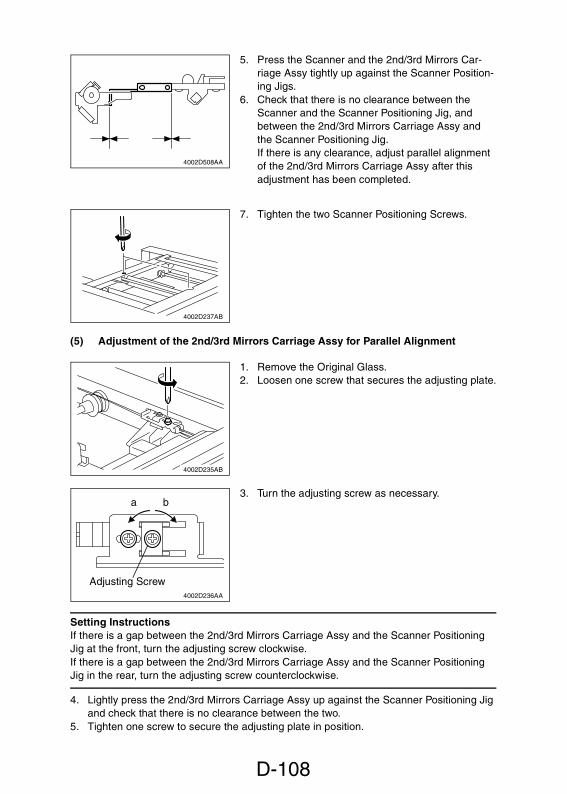
D-108
(5) Adjustment of the 2nd/3rd Mirrors Carriage Assy for Parallel Alignment
Setting InstructionsIf there is a gap between the 2nd/3rd Mirrors Carriage Assy and the Scanner PositioningJig at the front, turn the adjusting screw clockwise.If there is a gap between the 2nd/3rd Mirrors Carriage Assy and the Scanner PositioningJig in the rear, turn the adjusting screw counterclockwise.
4. Lightly press the 2nd/3rd Mirrors Carriage Assy up against the Scanner Positioning Jigand check that there is no clearance between the two.
5. Tighten one screw to secure the adjusting plate in position.
5. Press the Scanner and the 2nd/3rd Mirrors Car-riage Assy tightly up against the Scanner Position-ing Jigs.
6. Check that there is no clearance between theScanner and the Scanner Positioning Jig, andbetween the 2nd/3rd Mirrors Carriage Assy andthe Scanner Positioning Jig.If there is any clearance, adjust parallel alignmentof the 2nd/3rd Mirrors Carriage Assy after thisadjustment has been completed.
4002D508AA
7. Tighten the two Scanner Positioning Screws.
4002D237AB
1. Remove the Original Glass.2. Loosen one screw that secures the adjusting plate.
4002D235AB
3. Turn the adjusting screw as necessary.
4002D236AA
Adjusting Screw
a b

D-109
(6) Adjustment of the Gap Between the Doctor Blade and Sleeve Roller
(D.B. Adjustment)
RequirementThe gap between the Doctor Blade and Sleeve Roller should be 0.6 + 0.03 - 0.05 mm.
Adjustment Procedure1. Slide out the Developer Unit and remove the PC
Drum Charge Corona and PC Drum.2. Remove two screws and the Developer Scattering
Prevention Plate.
4002D224AA
3. Using a brush, whisk developer off the surface ofthe Sleeve Roller.
4002D225AA
4. Install the Sleeve/Magnet Roller Positioning Jig intothe Developer Unit.
1136D051AA
5. Loosen three screws that secure the Doctor Blade.Insert the D.B. Adjusting Jigs between the DoctorBlade and Sleeve Roller.
6. Press down the Doctor Blade until it positively con-tacts the D.B. Adjusting Jigs. Then, tighten thethree screws to secure the Doctor Blade.
4002D226AA

D-110
4. MISCELLANEOUS4-1. INSTALLATION OF THE KEY COUNTER SOCKET (OPTION)
1. Remove the Right Cover.2. Remove the Counter Cover.
4002D227AA
3. Swing down the Front Door and slide out theDeveloper Unit.
4. Remove three screws and the cover.
NOTEDo not remove the belt mounting screw on the cover.
4002D075AB
5. Connect the Key Counter Socket connector.6. Using one screw and nut, secure the counter
socket.
NOTEWhen the Key Counter Socket is mounted, set to “ON”the “Key Counter” available from the Security mode.
4002D228AB

D-111
4-2. MOUNTING THE ORIGINAL SIZE DETECTING SENSORS
(OPTION)
NOTEWhen an Original Size Detecting Sensor has been added, turn “ON” “Original Size Detect-ing Option” of “System Input” under the Tech. Rep. mode and make the “Orig. Size Adjust-ment.”� D-80
1. Remove the Original Glass and EDH Glass.2. Install the Original Size Detecting Sensor.
✽ 1: Standard for the Except U.S.A., Canada✽ 2: Standard for the Other Areas (Except Korea, Taiwan)✽ 3: Mount the sensor in hole D for Korea and Taiwan.
Mount it in hole E for areas other than Korea and Taiwan.
4002D268AB
FD3 (✽2)
FD1 (✽1)
CD2 (✽2)
(✽3)
A
G

D-112
4-3. FLASH MEMORYSoftware has conventionally been upgraded by replacing ROM on each board. This copieremploys flash memory for the system control IC mounted on the Master Board and ImageProcessing Board. Its contents are reprogrammed easily by performing the following stepsusing the IC card (memory card), into which data has been previously downloaded.
NOTES• NEVER remove or insert the memory card with the copier power turned ON.• An error code appears on the Touch Panel while data is being rewritten. It does not, how-
ever, indicate any problematic symptom and can be ignored.
(1) Rewriting the Master Board Data
1. With the Power Switch in the OFF position, unplug the power cord from the power out-let.
2. Remove the Rear Cover.
3. Insert the memory card into the Master Board.
4002D229AC
4. Plug the power cord into the power outlet.5. Turn ON the Power Switch.6. This starts the data rewriting sequence.
NOTEWhile the data is being rewritten, LD3 on the MasterBoard remains blinking and LD4 remains OFF.
7. Check that LD3 and LD4 on the Master Board turnON.
LD
7L
D6
LD
3L
D5
LD4
4002D267AA
8. Unplug the power cord from the power outlet.
NOTEDo not turn OFF the Power Switch at this time.
9. Remove the memory card.
4002D230AA

D-113
10. Turn OFF the Power Switch.11. Plug the power cord into the power outlet.12. Turn ON the Power Switch.13. Call the Tech. Rep. Mode to the screen.14. Touch [ROM Version].15. Check to see if the printer version shown on the screen matches the version marked on
the flash memory.
(2) Rewriting the Image Processing Board Data
1. With the Power Switch in the OFF position, unplug the power cord from the power out-let.
2. Remove the Right Cover.3. Close the Front Cover.
4. Remove three screws and the PH Cooling FanMotor mounting bracket Assy.
NOTEDo not disconnect the connector of the PH CoolingFan Motor.
5. Remove six screws and the mounting bracket.4002D046AB
6. Insert the memory card into the Image ProcessingBoard.
4002D231AB
7. Plug the power cord into the power outlet.8. Holding down the particular numeric key of the 10-
Key Pad corresponding to the language in whichthe data is to be rewritten, turn ON the PowerSwitch.
NOTEFor the specific numeric key of the 10-Key Pad, refer tothe “List of Numeric Keys Corresponding to Lan-guages.”� D-114
9. The data rewriting sequence starts.(The Start key starts blinking red.)
10. Check that a message appears on the TouchPanel, indicating that the data has been rewrittencorrectly.(The Start key lights up green steadily.)
1154D277AA

D-114
<List of Numeric Keys Corresponding to Languages>
10-Key Pad None pressed 1 2 3 4
MarketingAreas
U.S.A. andCanada
Europe 1 Europe 2 Europe 3Other
Areas 1Other
Areas 2
Languages
English English English English English English
French German Ukrainian Czech Spanish Chinese 1
Spanish French Lithuanian Slovak Portuguese Chinese 2
Japanese Dutch Estonian Turkish French Japanese
Italian Hungarian French Russian
Spanish Romanian German Thai
Portuguese Polish Greek Malay
Danish Croatian Chinese Indonesian
Norwegian German Arabic Arabic
Swedish Russian Slovenian Japanese
Finnish Chinese 1
Japanese Chinese 2
Check Items• “Downloading Completed.” is shown.• The number shown to the left of “Language”
matches that entered from the 10-Key Pad when thePower Switch is turned ON.
• The Check Sum value matches the value given onthe memory card.
11. If rewriting has been NG (as indicated by the Startkey lighting up red), perform steps 12 and 13 andthen start the procedure over, beginning with step5.
NOTEIf the second rewriting fails, perform steps 12 and 13and abandon the procedure.
12. Unplug the power cord from the power outlet.
NOTEAt this time, do not turn OFF the Power Switch.
13. Remove the memory card.
4002D233AA

D-115
(3) Rewriting the ECC Board Data (option)
1. Unplug the power cord from the power outlet with the Power Switch OFF.2. Remove the Rear Cover.
3. Insert the memory card into the ECC Board.
4002D538AB
4. Plug the power cord into the power outlet.5. Turn ON the Power Switch.6. This starts the rewriting sequence.
NOTED1 on the Master Board remains blinking while data isbeing rewritten.
7. Check that D3 on the ECC Board turns ON.8. If an LED other than D3 turns ON or if it takes
longer than 3 min. to rewrite the data, performsteps 9 and 10, turn OFF the Power Switch, andstart the procedure over beginning with step 4.
4002D540AB
9. Unplug the power cord from the power outlet.
NOTEAt this time, do not turn OFF the Power Switch.
10. Remove the memory card.
4002D539AB

D-116
(4) Rewriting the Master Board, Image Processing Board, and ECC Board (Option)
Simultaneously
NOTESteps 4 and 9 are to be performed only when the ECC Board (option) is mounted.
1. With the Power Switch in the OFF position, unplug the power cord from the power out-let.
2. Insert the memory card into the Image Processing Board.� D-1133. Insert the memory card into the Master Board.� D-1124. Insert the memory card into the ECC Board.� D-1155. Plug the power cord into the power outlet.6. Turn ON the Power Switch.
10. Unplug the power cord from the power outlet.
NOTEDo not turn OFF the Power Switch at this time.
11. Remove the memory card.
7. Check that a message appears on the TouchPanel, indicating that the data has been rewrittencorrectly.
Check Items• “Downloading Completed.” is shown.• The number shown to the left of “Language”
matches that entered from the 10-Key Pad when thePower Switch is turned ON.
• The Check Sum value matches the value given onthe memory card.
4002D525AA
8. Check that LD3 and LD4 on the Master Board areON.
LD
7L
D6
LD
3L
D5
LD4
4002D267AA
9. Check that D3 on the ECC Board turns ON.
4002D540AB

D-117
4-4. REMOUNTING EPROM
NOTEIf the PW Board has replaced, be sure to remount EPROM from the old to new PW Board.If the PW Board has been replaced and EPROM has not been remounted, be sure toreplace the PC Drum with a new one. EPROM contains no data in this case, so makeentries again of numeric values given on the Adjust Label.
(1) Remounting EPROM on the Master Board
1. Remove the Master Board.2. Remove EPROM (IC101) from the new Master Board.3. Remove EPROM (IC101) from old Master Board and remount it onto the new Master
Board.
4002D529AA
NOTENote the alignment notch (A) on EPROM (IC101) whenmounting the IC.
4002D530AA
A

D-118
(2) Remounting EPROM on the Image Processing Board
1. Remove the Image Processing Board.2. Remove EPROM (IC400) from the new Image Processing Board.3. Remove EPROM (IC400) from old Image Processing Board and remount it onto the
new Image Processing Board.
4002D254AB
NOTENote the alignment notch (A) on EPROM (IC400) whenmounting the IC.
4002D255AB
A

SWITCHES ON PWBs,TECH. REP. SETTINGS


i
CONTENTS1. CONTROL PANEL KEYS AND TOUCH PANEL .............................................S-1
1-1. Control Panel Keys ..................................................................................S-11-2. Explanation of the Touch Panel ...............................................................S-3
(1) Basis Screen ...................................................................................S-3(2) Warning Screens ............................................................................. S-4
2. FUNCTION OF SWITCHES AND OTHER PARTS ON PWBs ........................S-52-1. PWB Location ..........................................................................................S-52-2. PWB-S (Tech. Rep. Setting Switches Board) ..........................................S-5
(1) Clearing Procedures ........................................................................S-6(2) Data/Conditions Cleared by Reset Switches/Pins ...........................S-6
3. UTILITY MODE ................................................................................................ S-73-1. Utility Mode selection Screen ..................................................................S-73-2. Utility Mode Function Tree .......................................................................S-73-3. Settings in the Utility Mode ......................................................................S-8
(1) User’s Choice Mode ........................................................................S-8(2) Administrator Mode ......................................................................... S-15
4. TECH. REP. MODE .........................................................................................S-174-1. Tech. Rep. Mode Menu Screen ...............................................................S-174-2. Tech. Rep. Mode Function Setting Procedure .........................................S-174-3. Tech. Rep. Mode Menu Function Tree ....................................................S-184-4. Setting in the Tech. Rep. Mode ...............................................................S-21
(1) Function ...........................................................................................S-21(2) Tech. Rep. Choice ........................................................................... S-24(3) System Input ....................................................................................S-26(4) Counter ............................................................................................S-27(5) I/O Check .........................................................................................S-32(6) I.R. & EDH Check ............................................................................S-32(7) ROM Version ...................................................................................S-33(8) RD Mode .........................................................................................S-34(9) Level History ....................................................................................S-36(10) Admin. Mode ...................................................................................S-37(11) Finisher ............................................................................................S-37
5. SECURITY MODE ...........................................................................................S-385-1. Security Mode Menu Screen ...................................................................S-385-2. Security Mode Setting Procedure ............................................................S-385-3. Settings in the Security Mode ..................................................................S-39
6. ADJUST MODE ...............................................................................................S-416-1. Adjust Mode Menu Screen ......................................................................S-416-2. Adjust Mode Setting Procedure ...............................................................S-416-3. Adjust Mode Function Tree ......................................................................S-426-4. Settings in the Adjust Mode .....................................................................S-43


S-1
1. CONTROL PANEL KEYS AND TOUCH PANEL1-1. Control Panel Keys
1 2 3 4
5
7
8
9
10
6
11
12
1314
15
16
17
18
1920
4002O279EA

S-2
1. HDD Lamp• Lights up to indicate that the Hard Disk
Drive Kit (option) is being accessed.2. Access Key• Press to enter the access number when
Copy Track of the Administrator modeavailable.Press the access Key.
3. Energy Saver Key• Press to set machine into the Energy
Saver mode.4. Interrupt Key• Press to select the Interrupt mode.5. Panel Reset Key• Press to set the machine into the initial
mode, clearing all settings made on thecontrol panel.
6. Clear Key• Clear the various numeric values.7. Stop Key• Stop a print cycle.• Stop a scanning cycle.8. Start Key• Start a print cycle.9. Touch Panel• Shows various screens and message.10. Mode Check Key• Press to show the Mode Check screen.
11. Original Key• Press to select the Mixed Orig. Detec-
tion and other document-related func-tions setting screen.
12. Job List Key• Press to check for the settings made for
a job (Mode Check), modify the settingsof a job (Change), delete a job (Delete),and unlock a job (Unlock).
13. Ready Key• Lights up to indicate that data can be
transferred.14. On Line Key• Press to select either Online or Offline
mode.15. Display Contrast Knob• Use to adjust the brightness of the
Touch Panel.16. Utility Key• Press to show the Utility Mode menu.17. Job Recall Key• Press to show the Job Recall screen on
which you can check or recall a copy-job program previously stored in mem-ory.
18. 10-Key pad• The number of copies to be made.• The various numeric values.19. Scan Key• Press to select the Scanner mode.20. Copy Key• Press to select the Copy mode.

S-3
1-2. Explanation of the Touch Panel(1) Basis Screen
The Basic screen is the initial screen that appears when the copier is turned ON.
1. Supplementary Function Keys• The auxiliary, Density, Orig. Copy, and Basics keys are displayed.2. Message Display• Shows the current machine status, operating instructions and precautions, and other
data including the number of copies selected and the amount of paper still available foruse.
3. Basic Function/Key• Shows the basic function keys and the corresponding functions currently selected for
use.4. Set Function• Shows graphic representations of the settings currently made for Orig. Copy and Fin-
ishing.5. Sub-message Display• Shows what is being done with the currently reserved job.
1
2
3
4
5
4003P137CA

S-4
(2) Warning Screens
The Warning screen may be a malfunction display, error display, warning display, or a cau-tion display.
<Malfunction Display>Given when a malfunction occurs.E.g.: Malfunctions that can be identified with a specific code.
4003P201CA 4003P200CA
4003P189CA 4003P601DA
<Error Display>Given when an error occurs.E.g.: Paper misfeed, door open, etc.
<Warning Display>Given when only a defective copy will beproduced because of erroneous or illegalpanel settings.E.g.: Unmatched paper size in Auto Paper.
4003P185CA
<Caution Display>Given when, though further copier opera-tion will be possible, it could eventuallyresult in a malfunction.E.g.: Toner near empty, etc.

S-5
2. FUNCTION OF SWITCHES AND OTHER PARTS ON
PWBs2-1. PWB Location
2-2. PWB-S (Tech. Rep. Setting Switches Board)
Symbol Name Description
S25 Trouble Reset Switch Resets the malfunction display.
S26 Tech. Rep. Switch Display the Tech. Rep. mode screen.
PJ2 Initialize Switch Resets a misfeed, malfunction, anderratic display.
TP1 Memory Clear Test Point Clears all data.
NOTE:• It does not, however, clear data of
Electronic counters, Adjust mode,Administrator and RD mode func-tions.
TP3 COM Test Point Ground used for memory clear.
4002S001AB
PWB-S
4002S002AB

S-6
(1) Clearing Procedures
<Initialize>1. Turn OFF the Power Switch.2. With the circuit across pins of PJ2 closed, turn ON the Power Switch.3. Open the circuit in about 5 seconds.4. Check that the message “Initialize Completed” is displayed on the Touch Panel and then
touch the “OK” key.
<Memory Clear>1. Turn OFF the Power Switch.2. With the circuit across TP1 and TP3 closed, turn ON the Power Switch.3. Open the circuit in about 5 seconds.4. Check that the message “Memory Clear Completed” is displayed on the Touch Panel
and then touch the “OK” key.
NOTES:• If the copier exhibits an erratic display or operation, reset and clear in the following order:
Initialize � Memory Clear.• If Memory Clear has been performed, make settings of various functions once again.
(2) Data/Conditions Cleared by Reset Switches/Pins
❍: Cleared –: Not cleared
Clearing Method
Data Cleared
Front DoorOpen/Close
Trouble ResetSwitch S25
InitializePJ2
MemoryClearTP1
Misfeed display ❍ – ❍ ❍
Malfunctiondisplay
Fusing/Optical
– ❍ ❍ ❍
Others ❍ ❍ ❍ ❍
Erratic operation/display – ❍ ❍ ❍
Job/Image – – – ❍
User’s Choice – – – ❍
Tech. Rep. Mode – – – ❍
Security Mode – – – ❍

S-7
3. UTILITY MODE• Utility Mode is used to make various settings according to the user’s need.
3-1. Utility Mode selection Screen• Press the Utility key on the control panel.
3-2. Utility Mode Function Tree
✽ 1: The description of the function displayed on the Touch Panel is “Disable Sleep” whena Printer Controller is connected to the machine and “Disable Auto Shut off” when oneis not connected.
✽ 2: The description of the function is displayed when a Data Terminal is connected to themachine.
4003P605CA
Job Memory InputImage Memory Input
User’s Choice 1/6User’s Choice 2/6User’s Choice 3/6User’s Choice 4/6User’s Choice 5/6User’s Choice 6/6
Copy TrackCopy Track DataMax. Copy SetsDisable Auto Shut offData Send
Utility
Job/Image Mem. Input
Meter Count
User’s Choice
Administrator Mode
Toner Replenisher
✽ 1✽ 2

S-8
3-3. Settings in the Utility Mode
(1) User’s Choice Mode
• User’s Choice is used to make various settings according to the user’s need.
1. User’s Choice Function Setting Procedure<Procedure>1. Press the Utility key.2. Touch the “User’s Choice” key.3. Select the appropriate screen from the menu.4. Select the appropriate function.5. After the settings are complete, touch the “Enter” key to validate the settings.
<Exiting the Mode>• Press the Panel Reset key.
Touch PanelDisplay
Setting
Job/ImageMen. Input
Permits programming of various functions, including copying jobs.
Meter Count Displays the counts of various counters.
User’s Choice User’s Choice is used to make various settings according to the user’sneed.
AdministratorMode
The entry of the “Administrator #” set using the Tech. Rep. mode per-mits the settings of the following functions.
Toner Replenisher Replenishes the supply of toner.

S-9
2. User’s Choice Function Tree
✽ The function displayed on the Touch Panel is “Sleep” when a Printer Controller is con-nected to the machine and “Auto Shut off” when one is not connected.
Original Copy Default
Language selected
User’s Choice 1/6 Mixed Original Detect
Memory Recall
Auto Paper/Auto Size
Tray Priority
2in1, 4in1, Booklet, copy Zoom
Density Priority
User’s Choice 2/6 Default Level
Output Priority
Intelligent Sorting
Criss Cross Mode
“Small” Originals
4in1 Copy Order
User’s Choice Mode User’s Choice 3/6 Date Printing Format
Date Printing Position
Page Number Position
User’s Choice 4/6 Confirmation Beep
Universal Tray
Special Paper
User’s Choice 5/6 Auto Panel Reset
Energy Save Mode
Plug-in Counter Reset
✽ Sleep
Date/Time Set
Print Exposure
User’s Choice 6/6 Priority Device
Density (ADF)
Priority Offset Tray

S-10
3. Settings in the User’s Choice Mode
Touch PanelDisplay Setting (The default is ).
Original CopyDefault
Select the priority type of Original Copy setting selected automati-cally when the Power Switch is turned ON or Panel Reset keypressed.
Languageselected
Select the language of the Touch Panel messages.
Mixed OriginalDetect
Select the priority Mixed Original Detection mode that is automaticallyselected when the Power Switch is turned ON or Panel Reset keypressed.
Memory Recall Select whether to enable or disable the Memory Recall function.
Auto Paper/AutoSize
Select the priority Auto mode (Auto Paper or Auto Size) selectedwhen the Power Switch is turned ON or Panel Reset key pressed.
Tray Priority Select the priority paper source that is automatically selected whenthe copier is set into the Auto Size or Manual mode.
2in1, 4in1,Booklet CopyZoom
Select whether to enable or disable recalling a default zoom ratiowhen Auto Paper is selected for 2in1, 4in1, or Booklet Creation.
Highlighted
1-Sided 2-Sided 2-Sided 2-Sided1-Sided 1-Sided
<Metric Areas> <Inch Areas>
GERMAN FRENCH FRENCH SPANISH
DUTCH ITALIAN SPANISH JAPANESE
PORTUGUESE DANISH NORWEGIAN
SWEDISH FINISH JAPANESE
ENGLISH ENGLISH
ON OFF
ON OFF
Auto Size ManualAuto Paper
2nd Drawer
3rd Drawer 4th Drawer
LCT
1st Drawer
<2in1 4in1>
OFFON
<Booklet Creation>
OFFON

S-11
Touch PanelDisplay Setting (The default is ).
Density Priority Specify the priority exposure mode that is selected automaticallywhen the Power Switch is turned ON or the Panel Reset key pressed.
Default Level Auto: Select the priority exposure level in the Auto Exposure mode.Manual: Select the priority exposure level in the Manual Exposuremode.
Output Priority Select the priority finishing type.
NOTE:• The contents of the display vary depending on the types of finishing
options mounted on the machine.
Intelligent Sorting Select whether to enable or disable the function that automaticallyswitches between Sort and Non-Sort according to the number of orig-inals and the number of copy sets to be made.Applicable when the system is equipped with a finishing option andusing an EDH.
Criss Cross Mode Select whether to enable or disable crisscross sorting automatically.
Highlighted
<Density>
<Original Image Type>
Manual
Text/Photo Photo
Auto Exposure
Text
<Auto>
<Manual>
Lighter DarkerNormal
Lighter Darker
Corner Staple 2-Hole Punch
Sort 2-Point Staple 3-Hole Punch
Group
Non Sort
OFFON
OFFON

S-12
Touch PanelDisplay Setting (The default is ).
“Smaller” Originals Select whether to enable or disable a copy cycle when it is initiatedwith an original of a small size that is not detectable by the systemplaced on the Original Glass.
✽ Default: Metric areas OFF/Inch Areas ON.
4in1 Copy Order Specify the default copying order in the 4in1 mode.
Date PrintingFormat
Select the delimiter and format for date printing.
Date PrintingPosition
Select the position at which to print the date.
Page NumberPosition
Set the position at which to print the page number, how many millime-ters or inches from the bottom of the page.
Confirmation Beep Select whether to enable or disable the beep that sounds each time akey on the control panel is pressed or a function on the Touch Paneltouched.
Highlighted
ON OFF
21
3 4
31
2 4
<Punctuation>
<Year>
<Date Format>
X X. X X. X X
yyyy
DEC/24/’00 24/DEC/’00
12/24/’00 24/12/’00
X X / X X / X X
’yy
’00/12/24
<Metric Areas> <Inch Areas>
X 4 to 40 ( ) X 3/16 to 1-9/16” ( )
Y 4 to 40 ( ) Y 3/16 to 1-9/16” ( )
8 mm 1/4”
20 mm 3/4”
<Metric Areas> <Inch Areas>
4 to 40 ( ) 3/16 to 1-9/16” ( )8 mm 1/4”
OFFON

S-13
Touch PanelDisplay Setting (The default is ).
Universal Tray Set the paper size for the Universal Tray.
Special Paper Define the type of paper used for each paper source, or designate aparticular paper source for special paper.
Auto Panel Reset Select the time it takes the Auto Panel Reset function, which resetsthe panel settings when the set period of time elapses after a copycycle has been completed or the last key operated, to be activated.
Energy SaverMode
Select the time it takes the copier to enter the Energy Saver modeafter a copy cycle has been completed or the last key operated.Use the 10-Key Pad to set the time.
Plug-In CounterReset
Select whether or not to activate the Panel Reset function when thePlug-In Counter or a magnetic card is pulled out.
Sleep
✽ When a PrinterController isconnected.
Select the time it takes the Sleep function, which shuts down thecopier when the set period of time elapses after a copy cycle hasbeen completed or the last key operated, to be activated.
NOTE:• The option of “OFF” becomes available on the screen if “Yes” is
selected for “Disable Sleep” of the “Administrator Mode” function.
Highlighted
Size InputAuto Detect
Cover/Insert
Recycled Cover
Not for 2-Sided Insert
Normal
30 sec. 2 min.
3 min. 5 min. No Reset
1 min.
1 to 90 ( )15 min.
OFFON
OFF 15 to 90 ( )90 min.

S-14
Touch PanelDisplay Setting (The default is ).
Auto Shut-OffMode
✽ When a PrinterController is notconnected.
Select the time it takes the Auto Shut Off function, which shuts downthe copier when the set period of time elapses after a copy cycle hasbeen completed or the last key operated, to be activated.
NOTE:• The option of “OFF” becomes available on the screen if “Yes” is
selected for “Disable Auto Shut off” of the “Administrator Mode”function.
Date/Time Set Set the date and time-of-day for Date Printing.
Print Exposure Set the image density level for printing.
Priority Device Select the priority configuration of the copier established when thePower Switch is turned ON or the Panel Reset key pressed.
Density (ADF) Adjust the copy image density level when the ADF is being used.
Priority Offset Tray Select the particular Offset Tray to which priority is given.
Highlighted
OFF 15 to 90 ( )90 min.
Year 1999 to 2089 Month 1 to 12
Day 1 to 31 Time00 to 23 (hour)00 to 59 (min)
Lighter DarkerNormal
PrinterCopier
Mode 1 When the standard original (text, etc.) is used.
To give better reproduction of faint original.Mode 2
Bottom TrayTop Tray

S-15
(2) Administrator Mode
• The entry of the “Administrator #” set using the Tech. Rep. mode permits the settings ofthe following functions.
1. Administrator Mode Function Setting Procedure<Procedure>1. Press the Utility key.2. Touch the “Administrator Mode” key.3. Enter the Administrator number.4. Select the appropriate function.5. After the settings are complete, touch the “Enter” key to validate the settings.
<Exiting the Mode>• Press the Panel Reset key.
2. Settings in the Administrator Mode
Touch PanelDisplay Setting (The default is ).
Copy Track Select the number of accounts to be controlled.
NOTE:• Printer is displayed when an external I/F is connected.
Copy Track Select whether or not to initialize the copy track data so far taken.
Copy Track Data Select the particular account number.When “All Counter Reset” is touched, it clears all data under control.
Highlighted
-Copy Track-
<Copy> <Printer>
ON ON
OFF OFF
-Copy Track method-
100 Accounts
1000 Accounts
Yes (initialize) No (do not initialize)

S-16
Touch PanelDisplay Setting (The default is ).
100 Accounts The copy track data of the selected page is displayed.“No.”: Enter the set account number from the 10-Key Pad.“Total Count”: Displays the count of the Total Counter.“Size Count”: Displays the count of the Size Counter.“Copy Limit”: Enter the maximum number of copies that can be madefrom the 10-Key Pad.“Access Code”: Enter the access number, which can range from 0001to 9999, from the 10-Key Pad.These data can be cleared with the Clear key.
1000 Accounts The copy track data of the selected page is displayed.“No.”: Displays the account number. (Setting cannot be changed.)“Total Count”: Displays the count of the Total Counter. (It can becleared with the Clear key.)
NOTE:• The account number corresponds to the access code (ID) of that
particular account.
Permission Level Determine the number of copies or copy sets that can be set using the10-Key Pad.
Disable Sleep
✽ When a PrinterController isconnected.
Select whether to enable or disable the setting of the “Sleep” functionavailable from User’s Choice.
Disable AutoShut off
✽ When a PrinterController is notconnected.
Select whether to enable or disable the setting of the “Auto Shut Off”function available from User’s Choice.
Data Send Transmits various data to the Center when a Data Terminal ismounted.
Highlighted
1 to 99 OFF
Not displayed.
Yes Displayed.
No
Not displayed.
Yes Displayed.
No

S-17
4. TECH. REP. MODE• This mode is used by the Tech. Rep. to check, set, adjust, and/or program various ser-
vice functions.
4-1. Tech. Rep. Mode Menu Screen
4-2. Tech. Rep. Mode Function Setting Procedure<Procedure>1. Press the Utility key.2. Press the Meter Count key.3. Press the following keys in this order:
Stop � 0 � 0 � Stop � 0 � 14. Select the desired Tech. Rep. Mode function.
<Exiting the Mode>• Press the Panel Reset key.
4003P602CA

S-18
4-3. Tech. Rep. Mode Menu Function Tree
F1: Paper PassageF2: HV OutputF5: AIDC SensorF8: ATDC SensorF12: Test Pattern
Opt. Mem. CheckMemory CheckComp./Expansion
I.R. Mem. Prn.Hard Disk FormatHard Disk CheckECC CheckDate/Time Check
�� ��
FLS PaperAuto Paper ConfigurationFunction LimitTouch Panel Adj.Smoothing (Text)Maintenance CallUniversal Tray
Toner Empty StopT/C AbnormalFusing (°C) InputT/C Auto Recover
Controller TypeMain. Sw noticePrinter Time-outWarning LevelPeripheral Mode
Change Fixed ZoomPaper Size InputMarketing AreaOrig. Size OptionTel. # InputHard Disk
PaperMaintenanceJamPMConsumablesTrouble
~
Tech. Rep. Mode
Function
Tech. Rep.Choice
System Input
Counter
Printer
ImageMemory
System Set
Printer
ControllerSet

S-19
Focus CheckZoom (CD)Zoom (FD)/ScaleScale (CD)Scanning CheckOrig. Size Adjust
Position/Zoom (FD)Position (CD)S-ADF Mode (CD)S-ADF Mode (FD)Skew Check
1-Sided2-SidedAuto sizeSingle Feed
~
~
Tech. Rep. Mode
I/O Check
I.R. & EDH Check
ROM Version
RD Mode
Level History
Admin. Mode
Erasure WidthID in Photo Mode
Function(IR)
Function(EDH)
I/O Check(IR)
I/O Check(EDH)
Tech. RepChoice
EDH PaperPassage

S-20
~
Punch LoopAdjust
Tech. Rep. Mode
SensorsPort Signals
Finisher
I/O Check

S-21
4-4. Setting in the Tech. Rep. Mode(1) Function
• This function allows the Tech. Rep. to make the various function tests and adjustments.<Functions>Printer: Used for making the various function tests and adjustments for the printer.Image Memory: Used for making the various function tests and adjustments for imagememory.
Touch PanelDisplay
Operation
F1:Paper Passage
A check is made for paper passage performance.<Procedure>1. Select the paper source.2. Touch “Duplex” for paper passage output on paper fed from the
Duplex Unit.3. Press the Start key to start the paper passage cycle.4. Press the Stop key to stop the paper passage cycle.
F2: HV Output This test is for factory adjustment only and should NOT be used.
F5: AIDC Sensor Adjusts the output level of the AIDC Sensor.✽ For details, see DIS/REASSEMBLY, ADJUSTMENT.
F8: ATDC Sensor Adjusts the output level of the ATDC Sensor.✽ For details, see DIS/REASSEMBLY, ADJUSTMENT.
F12: Test Pattern Outputs the test pattern.<Procedure>1. Touch “Duplex” for test pattern output on paper fed from the
Duplex Unit.2. Select the test pattern type.3. Select the paper source.4. Press the Start key to start the output sequence.5. Press the Stop key to stop the output sequence.
Opt. Men. Check Checks for the connection of optional memory.
Display Type Display Type
F12-0 Dots F12-5 ID self printing
F12-1 Gradation F12-6 Double dots
F12-2 Halftone F12-7 45° slant line
F12-3 64-dot checkered F12-8 2-dot line pair
F12-4 Solid black F12-9LD beam positioncorrection

S-22
Touch PanelDisplay
Operation
Memory Check Writes data in the image memory and reads it out to check for exactcorrespondence.The Touch Panel shows the percentage of processing completed ofeach diagnostic sequence and the number of diagnostic sequencescarried out. If a fault is encountered, it gives the message of “NG”together with the address at which the fault occurred.<Procedure>1. Press the Start key to start the diagnostic sequence.2. Press the Stop key to stop the diagnostic sequence.
Comp./Expansion Comp.: Checks to determine if the image data has been properlycompressed in memory.Expansion: Checks to determine if the compressed image data isproperly expanded in memory.The Touch Panel shows the percentage of processing completed ofthe diagnostic sequence. If the sequence has been completed okay, itgives the message of “OK”; if a fault was encountered, it gives themessage of “NG” together with the corresponding malfunction code.<Procedure>• Press the Start key to start the diagnostic sequence.
I.R. Mem. Prn. I.R. → Memory: Checks for correct image signal transfer between I.R.and memory.The Touch Panel shows the percentage of processing completed ofthe diagnostic sequence. If the sequence has been completed okay, itgives the message of “OK”; if a fault was encountered, it gives themessage of “NG” together with the corresponding malfunction code.<Procedure>1. Touch “IR → Memory”.2. Press the Start key to start the diagnostic sequence.
Memory → Printer: Checks for correct image signal transfer betweenmemory and printer.The Touch Panel shows the percentage of processing completed ofthe diagnostic sequence. If the sequence has been completed okay, itgives the message of “OK”; if a fault was encountered, it gives themessage of “NG” together with the corresponding malfunction code.During the sequence, the copier also produces a test copy which canbe checked for correct image.<Procedure>1. Touch either “Memory → Prn” or “Memory → Prn”.2. Load the Multi Bypass Table with A4 lengthwise paper.3. Press the Start key to start the diagnostic sequence.
�� ��
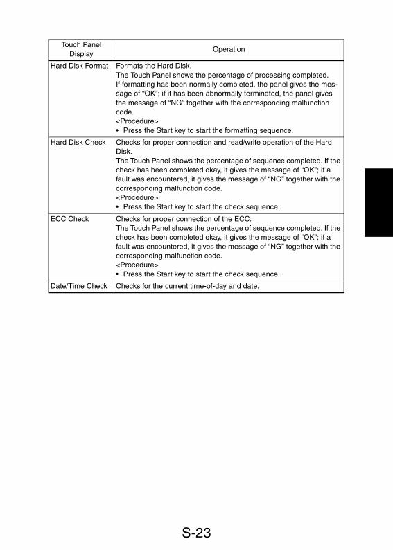
S-23
Touch PanelDisplay
Operation
Hard Disk Format Formats the Hard Disk.The Touch Panel shows the percentage of processing completed.If formatting has been normally completed, the panel gives the mes-sage of “OK”; if it has been abnormally terminated, the panel givesthe message of “NG” together with the corresponding malfunctioncode.<Procedure>• Press the Start key to start the formatting sequence.
Hard Disk Check Checks for proper connection and read/write operation of the HardDisk.The Touch Panel shows the percentage of sequence completed. If thecheck has been completed okay, it gives the message of “OK”; if afault was encountered, it gives the message of “NG” together with thecorresponding malfunction code.<Procedure>• Press the Start key to start the check sequence.
ECC Check Checks for proper connection of the ECC.The Touch Panel shows the percentage of sequence completed. If thecheck has been completed okay, it gives the message of “OK”; if afault was encountered, it gives the message of “NG” together with thecorresponding malfunction code.<Procedure>• Press the Start key to start the check sequence.
Date/Time Check Checks for the current time-of-day and date.

S-24
(2) Tech. Rep. Choice
• This function allows the Tech. Rep. to make various settings and adjustments.
<Functions>System Set: Choice functions relating to the printer.Printer: Choice functions relating to image memory.Controller Set: Choice functions relating to the Printer Controller.
Touch PanelDisplay Setting (The default is ).
FLS Paper Set the size for FLS.
Auto PaperConfiguration
Select the method of rounding of the detected original size.
Function Limit Select whether to limit the functions to be set on the control panel ornot.
Touch Panel Adj. Corrects deviation in the sensitive area of the Touch Panel.<Procedure>• Sequentially touch the four points marked with + on the screen.
NOTE:• Be sure to touch the exact center of the + marking.
Smoothing (Text) Select whether to turn ON or OFF the smoothing for function for theText mode.
Maintenance Call Select whether to enable or disable the maintenance call reminder(M1) message that is displayed when the maintenance counter countreaches the preset value.
Universal Tray Set the inch size of paper to be used.
Highlighted
F: 330.2 mmC: 203.2 mm
F: 330.2 mmC: 215.9 mm
F: 330 mmC: 220 mm
F: 330 mmC: 210 mm
The measurement is rounded to the neareststandard inch or metric size.
MetricThe measurement is rounded to the neareststandard metric size.
Inch/Metric
Enable
Limits the functions to the paper, zoom ratio, den-sity, number of copies to be made, Mixed Orig.Detection, Free Orig. Placement, and Small Orig.Adjustment.
Enables all functions (no Limit).Disable
OFFON
Call Indicated Call Not Indicated
14 × 81/4 14 × 81/2

S-25
Touch PanelDisplay Setting (The default is ).
Toner Empty Stop Select whether or not to inhibit copying when a toner-empty conditionis detected.
T/C Abnormal Select whether to enable or disable copying when an abnormal T/C isdetected.
Fusing (°C) Input Set the temperature for fusing temperature control according to theoperating environment and the type of paper used.
T/C Auto Recover Select whether to enable or disable auto recovery of T/C when itdrops.
Controller Type Set the type of the Printer Controller.
✽ After the setting has been made, touch “END” and turn OFF andON the Power Switch.
Main. Sw. notice Select the timing at which the Printer Controller power is turned ON.
✽ After the setting has been made, touch “END” and turn OFF andON the Power Switch.
Printer Time-Out Set the timeout period for the printer.
✽ After the setting has been made, touch “END” and turn OFF andON the Power Switch.
Warning Level Select the type of warning display given when an error occurs in thePrinter Controller.
✽ After the setting has been made, touch “END” and turn OFF andON the Power Switch.
Highlighted
DisableEnable
DisableEnable
1 3
180 °C 190 °C 195 °C
2
DisableEnable
0 to 9 ( )0
After the machine has completed its initial opera-tion.
Mode 2 When the machine is turned ON.
Mode 1
Disable 1 to 99 ( )10 min.
AttentionTrouble

S-26
(3) System Input
• This function allows the Tech. Rep. to change the fixed zoom ratios, set the paper size,define the marketing area, and make other settings.
Touch PanelDisplay Setting (The default is ).
Peripheral Mode Select the type of external I/F operation.
✽ After the setting has been made, touch “END” and turn OFF andON the Power Switch.
Touch PanelDisplay Setting (The default is ).
Change FixedZoom
Change a fixed zoom ratio to a desired value.<Procedure>1. Touch the key of the fixed zoom ratio to be changed.2. Press the Clear key.3. Enter the new ratio from the 10-Key Pad.4. Touch “Input” to validate the new setting.
Paper Size Input Set the paper size.<Procedure>1. Select the paper source.2. Select the paper size.3. Touch “END” to validate the new setting.
Marketing Area Set the marketing area.
Original SizeDetecting Option
Select “ON” when the optional Original Size Detecting Sensor ismounted.
Tel. # Input Enter the telephone number that will appear on the Touch Panel whena malfunction occurs in the copier.<Procedure>1. Enter the phone number from the 10-Key Pad. Use the Interrupt
key to enter a hyphen “-.”2. Touch “END” to validate the phone number setting.
Hard Disk Select “ON” if a Hard Disk is mounted.
Highlighted
Mode 1 External I/F operation mode 1
External I/F operation mode 2
Mode 3 External I/F operation mode 3
Mode 2
Highlighted
MSJ MC ME Other Areas
ON OFF
ON OFF

S-27
(4) Counter
• Shows the number of copies made on each paper size or type.
<Clearing a Count>1. Open the counter menu screen.2. Select the counter to be cleared.3. Press the Clear key.4. Touch “END”.
Press the Interrupt key to undo the clearing operation, restoring the original count.
<Clearing All Counts of a Counter Type at Once>1. Touch the “Counter Reset” key.2. Select the counters to be cleared all at once.3. Touch “OK”.
Touch PanelDisplay
Setting
Paper Counts the number of sheets of paper used according to the size andtype.
Maintenance Set different count values for the Maintenance Counter.When the preset count is reached, the maintenance call remindermessage and maintenance code “M1” appear on the Touch Panel.
NOTE:• Whether the maintenance call reminder message and maintenance
code is given or not depends on the setting made in Tech. Rep.Choice.
<Procedure>1. Touch “Maintenance Set”.2. Press the Clear key to clear the current value.
Press the Interrupt key to undo the clearing operation, restoringthe original value.
3. Enter the value from the 10-Key Pad.4. Touch “END”.
Paper size Paper Type
A3 11 × 17 Not-2-Sided
B4 11 × 14 Normal
A4 Letter Recycle
B5 Legal Cover
A5 5-1/2 × 8-1/2 Insert
B6 FLS Cover/Insert
A6 Executive

S-28
Touch PanelDisplay
Setting
Jam Counts the number of misfeeds that have occurred at different loca-tions in the copier.
Display Description
MCBJ System
MCBJ MachineOnlyManual Feed
1st Drawer2nd Drawer3rd Drawer4tht Drawer
Total Counter divided by the sum of all misfeed-counters (including misfeeds in the Finisher)Total Counter divided by the sum of machine mis-feed counter (excluding misfeeds in the Finisher)No. of misfeeds that occurred at the Multi BypassTrayNo. of misfeeds that occurred at the 1st DrawerNo. of misfeeds that occurred at the 2nd DrawerNo. of misfeeds that occurred at the 3rd DrawerNo. of misfeeds that occurred at the 4th Drawer
Display Description
LCTVertical Transport(Upper)Vertical Transport(Lower)Horizontal TransportSeparator
FusingTurnover
No. of misfeeds that occurred at the LCTNo. of misfeeds that occurred at the paper take-upupper vertical transport sectionNo. of misfeeds that occurred at the paper take-uplower vertical transport sectionNo. of misfeeds that occurred at the vertical trans-port sectionNo. of misfeeds that occurred at the paper separa-tion sectionNo. of misfeeds that occurred at the Fusing UnitNo. of misfeeds that occurred at the exit/turnoversection
Display Description
MCBJ (EDH)
EDH Feed
EDH Transport
EDH Reverse
EDH Exit
EDH Exit-Reverse
SADF Feed
EDH paper feed counter divided by EDH misfeedcounterNo. of misfeeds that occurred at the document take-up section of the EDHNo. of misfeeds that occurred at the documenttransport section of the EDHNo. of misfeeds that occurred at the document turn-over section of the EDHNo. of misfeeds that occurred at the document exitsection (straight) of the EDHNo. of misfeeds that occurred at the document exitsection (turnover) of the EDHNo. of misfeeds that occurred at the SADF

S-29
Touch PanelDisplay
Setting
Jam
PM Counts the frequency of use of each of the different parts of thecopier.
Display Description
FoldStapleFinisher
NeedleDuplex Entrance
Duplex Exit
No. of misfeeds that occurred at the Folding UnitNo. of misfeeds that occurred at the Stapling UnitNo. of misfeeds that occurred in the Finisher, otherthan aboveNo. of staple misfeeds that occurred.No. of misfeeds that occurred at the turnover/stor-age section of the Duplex UnitNo. of misfeeds that occurred at the horizontal trans-port section of the Duplex Unit
Display Description
Manual Feed1st Drawer2nd Drawer3rd Drawer (LCC)LCC Parts4th Drawer
No. of sheets of paper fed from the Multi Bypass TrayNo. of sheets of paper fed from the 1st DrawerNo. of sheets of paper fed from the 2nd DrawerNo. of sheets of paper fed from the 3rd DrawerNo. of sheets of paper fed from the 3rd DrawerNo. of sheets of paper fed from the 4th Drawer
Display Description
LCTLCT PartsPC Drum 1PC Drum 2PC Drum 3
No. of sheets of paper fed from the LCTNo. of sheets of paper fed from the LCTNo. of times a sheet of paper is fed throughNo. of times a sheet of paper is fed throughNo. of times a sheet of paper is fed through
Display Description
Developer 1
Developer 2
Others PM Parts 1Others PM Parts 2Cleaning 1Cleaning 2Cleaning 3
Time over which the PC Drum has turned (H), the num-ber of copies made as calculated from the time (K)Time over which the PC Drum has turned (H), the num-ber of copies made as calculated from the time (K)No. of times a sheet of paper is fed throughNo. of times a sheet of paper is fed throughNo. of times a sheet of paper is fed throughNo. of times a sheet of paper is fed throughNo. of times a sheet of paper is fed through
Display Description
Fusing UnitFusing RollerImage Reader
EDH SimplexEDH DuplexEDH Single FeedFold
No. of times a sheet of paper is fed throughNo. of times a sheet of paper is fed throughNo. of scan motions carried out for originals placedmanuallyNo. of scan motions carried out for 1-sided originalsNo. of scan motions carried out for 2-sided originalsNo. of scan motions carried out for single feedNo. of copies fed out in the Folding mode

S-30
Touch PanelDisplay
Setting
PM
✽ See MAINTENANCE SCHEDULE (machine/options) for the appli-cable parts.
Consumables Enter the count of the Waste Toner and Web Roller counters. Whenthe count reaches the set value, the maintenance code is displayed.
<Procedure>1. Touch “Set”.2. Press the Clear key to clear the current value.
Press the Interrupt key to undo the clearing operation, restoringthe original value.
3. Enter the value from the 10-Key Pad.4. Touch “END”.
Trouble Counts the number of malfunctions that have occurred at differentparts of the copier.
Display Description
Staple 1Staple 2PunchSort/GroupTrans./Sepa. passOzone Filter
No. of stapling sequences performedNo. of stapling sequences performed (FN-105)No. of holes made (FN-105)No. of copies fed out in the Sort/Group modeNo. of times a sheet of paper is fed throughNo. of times a sheet of paper is fed through
Waste Toner: Maintenance code “M2”
Description Maintenance code Machine stop
Initial setvalue
45 cpm Approx. 220 k 45 cpm
55 cpm Approx. 270 k 55 cpm
If the initialset value is
changed
45 cpmThe set value -Approx. 20 k
45 cpm Set value
55 cpmThe set value -Approx. 30 k
55 cpm Set value
Web: Maintenance code “M3”
Description Maintenance code Machine stop
Initial setvalue
45 cpm 460 k 45 cpm
55 cpm 470 k 55 cpm
If the initialset value is
changed
When the count reachesthe set value
45 cpm 480 k
55 cpm 500 k
Approx. 240 k
Approx. 300 k
480 k
500 k
✽ “-”: Subtract
MalfunctionCode
Description MalfunctionCode
Description
C0000 Main Drive Motor C004C Ventilation Fan
C0010 PC Drum Drive Motor C0045 Image Unit Cooling Fan
C0040 Suction Fan C0046 PH Cooling Fan 1
C0044 EDH Cooling Fan C0047 PH Cooling Fan 2

S-31
Touch PanelDisplay
Setting
TroubleMalfunction
Code Description MalfunctionCode Description
C004E/F Cooling Fan C0210 Transfer Corona
C0042 Fusing Unit Fan C04X0 Exposure Lamp
C0070/2 Toner Hopper Motor C05X0 Fusing Unit
C0090 Dev. Unit Drive Motor C0602 Scanner Drive
MalfunctionCode
Description MalfunctionCode
Description
C0650 Scanner Home C095X 4th Drawer
C090X 3rd Drawer C099X LCC
C091X 2nd Drawer C09CX LCT
C092X 1st Drawer
MalfunctionCode
Description MalfunctionCode
Description
C0B0X Finisher Transport C0B5X Staple Unit (Rotation)
C0B2X Staple Unit (CD direc-tion) C0B7X Punch
C0B3X Finisher Alignment C0B8X Finisher Shift Tray
C0B4X Finisher Staple Transport C0BAX Finisher Elevator Tray
MalfunctionCode
Description MalfunctionCode
Description
C0BCX Finisher Fold Unit C1200/3/4 Memory
C0E00 Main Erase C12XX Memory Board
C0F24 AIDC Sensor C128A/B/C Load TimeOut
C0F3X ATDC Sensor C128D/E Save TimeOut
MalfunctionCode Description
MalfunctionCode Description
C12A0/4 Peripheral Signal (Input) C13F0 SOS Sensor
C12A8/9/C Peripheral Signal(Output)
C1330 VD Trouble
C12CX HDD Trouble C13FA-8/A-C LaserBeam Adj. Trouble
C1300 Polygon Motor C13F9 Printer EEPROM Trouble

S-32
(5) I/O Check
• The following functions are used to locate the faulty spot.• Shows the states of the I/O ports when the copier is in the standby state.✽ For details, see TROUBLESHOOTING.
(6) I.R. & EDH Check
• Allows the Tech. Rep. to make the various functional tests and adjustments of the IR(EDH).
Touch PanelDisplay
Setting
Trouble
Touch PanelDisplay
Setting
Function (IR) Displays the screens used to adjust and check the IR.
Focus Check Adjusts the focus level and displays the results of the adjustmentmade.✽ For details, see DIS/REASSEMBLY, ADJUSTMENT.
Zoom (CD) Adjusts the zoom ratio in the CD direction and displays the results ofthe adjustment made.✽ For details, see DIS/REASSEMBLY, ADJUSTMENT.
Zoom (FD)/Scale Adjusts the zoom ratio and the position of the scale in the FD direc-tion, and displays the results of the adjustment made.✽ For details, see DIS/REASSEMBLY, ADJUSTMENT.
Scale (CD) Adjusts the position of the scale in the CD direction and displays theresults of the adjustment made.✽ For details, see DIS/REASSEMBLY, ADJUSTMENT.
MalfunctionCode
Description MalfunctionCode
Description
C1430 H. sysnc Trouble C1461/2 Serial GA Trouble
C143E EDH Trouble C1499 IR Cooling Fan
C1440 Gain Adjust Trouble C14XX IR Sequence Trouble
C1441 CCD Trouble C1802 SPC Error
Malfunction Code Description
C1803 Memory Check Trouble
C180X ECC Control Trouble
C10A1/2, C11EX Communication (IR)
C10A5/6, C11FX, C1326/34 Com. (Prin.)
C133B Communication (Option)
C10XX, C11XX Others
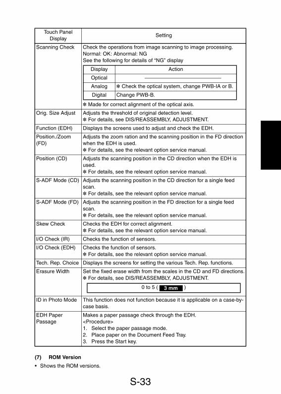
S-33
(7) ROM Version
• Shows the ROM versions.
Touch PanelDisplay
Setting
Scanning Check Check the operations from image scanning to image processing.Normal: OK: Abnormal: NGSee the following for details of “NG” display
✽ Made for correct alignment of the optical axis.
Orig. Size Adjust Adjusts the threshold of original detection level.✽ For details, see DIS/REASSEMBLY, ADJUSTMENT.
Function (EDH) Displays the screens used to adjust and check the EDH.
Position./Zoom(FD)
Adjusts the zoom ration and the scanning position in the FD directionwhen the EDH is used.✽ For details, see the relevant option service manual.
Position (CD) Adjusts the scanning position in the CD direction when the EDH isused.✽ For details, see the relevant option service manual.
S-ADF Mode (CD) Adjusts the scanning position in the CD direction for a single feedscan.✽ For details, see the relevant option service manual.
S-ADF Mode (FD) Adjusts the scanning position in the FD direction for a single feedscan.✽ For details, see the relevant option service manual.
Skew Check Checks the EDH for correct alignment.✽ For details, see the relevant option service manual.
I/O Check (IR) Checks the function of sensors.
I/O Check (EDH) Checks the function of sensors.✽ For details, see the relevant option service manual.
Tech. Rep. Choice Displays the screens for setting the various Tech. Rep. functions.
Erasure Width Set the fixed erase width from the scales in the CD and FD directions.✽ For details, see DIS/REASSEMBLY, ADJUSTMENT.
ID in Photo Mode This function does not function because it is applicable on a case-by-case basis.
EDH PaperPassage
Makes a paper passage check through the EDH.<Procedure>1. Select the paper passage mode.2. Place paper on the Document Feed Tray.3. Press the Start key.
Display Action
Optical
Analog ✽ Check the optical system, change PWB-IA or B.
Digital Change PWB-B.
0 to 5 ( )3 mm

S-34
(8) RD Mode
• Make the initial settings of the copier for the Data Terminal.
1. RD Mode Menu Function Tree
✽ The “System Set” portion is displayed when the machine has been set up for the Centerfor communication.
CT-ID
DT-ID
TEL. No.(Setting Modem)
Mail Address(Setting e-mail)
DT Setting
Maint.RAM Clear
YES
NO
Modem
CT-ID
DT-ID
TEL. No.(Setting Modem)
Mail Address(Setting e-mail)
InitialTransmission(Setting Modem)
DT Setting
BillingRAM Clear
YES
NO
ID Code
CallCompletion
Dial Mode
Tone
Pulse
Auto Receive
YES
NO
RD ModeInitialTransmission(Setting Modem)
System Set
Billing Center
Maint. Center
Date/Time
Common DT(Setting Modem)

S-35
2. Setting in the RD Mode
Touch PanelDisplay
Setting
System Set Set the control system.
Billing Center Displays the various setting screens.
DT Setting Displays the setting screens for CT-ID, DT-ID, and telephone number.The mail address is also displayed if “e-mail” is set for System Set.
CT-ID Enter the ID number of the Center PC from the 10-Key Pad.
DT-ID Enter the ID number of the Data Terminal from the 10-Key Pad.
TEL No. Enter the telephone number of the modem connected to the CenterPC.
InitialTransmission
Performs the initial transmission from the PPC to the Center to checkfor correct communication after the Data Terminal has been set up.
Billing RAM Clear Initializes the Data Terminal settings.
Maint. Center Displays the various setting screens.
ID Code Enter the ID code.<Procedure>1. Touch the ID Code key.2. Enter the ID code from the 10-Key Pad.3. Touch the ID Code key. (This executes the transmission of MAINT.
START to the Center.)
DT Setting Displays the setting screens for CT-ID, DT-ID, and telephone number.The mail address is also displayed if “e-mail” is set for System Set.
CT-ID Enter the ID number of the Center PC from the 10-Key Pad.
DT-ID Enter the ID number of the Data Terminal from the 10-Key Pad.
TEL No. Enter the telephone number of the modem connected to the CenterPC.
InitialTransmission
Performs the initial transmission from the PPC to the Center to checkfor correct communication after the Data Terminal has been set up.
Call Completion Transmits the signal of notifying the completion of service job to theCenter.
Maint. RAM Clear Initializes the Data Terminal settings.
e-mail Modem
YES NO
YES NO

S-36
(9) Level History
• Displays the various level histories.
Touch PanelDisplay
Setting
Date/Time Set Set the date and time-of-day for Date Printing.
Common DT Displays the screens for communications settings.
Dial Mode Sets the type of telephone line of the user.
Auto Receive Sets the auto reception function.
Touch PanelDisplay
Setting
Fuser (Upper) Displays the current value of the fusing temperature.
Fuser (Lower) Displays the current value of the fusing temperature.
ATDC Set Displays the voltage set with ATDC Sensor Automatic Adjustment(F8).
ATDC Current Displays the output voltage of the ATDC Sensor.
AIDC Fine Set Displays the AIDC Sensor LED control voltage.
AIDC Coarse Set Displays the load resistance level of the phototransistor used in theAIDC Sensor.
AIDC Current Displays the output voltage of the AIDC Sensor.
Vg Current Displays the current value of the grid voltage.
Vb Current Displays the current value of the developing bias voltage.
LD1 Displays the intensity value of LD1.
LD2 Displays the intensity value of LD2.
Tone Pulse
YES NO

S-37
(10) Admin. Mode
• Makes the various settings.
(11) Finisher
• Checks the Finisher for operation and makes necessary adjustments.
Touch PanelDisplay
Setting
Copy Track See User’s Choice.
Copy Track Data See User’s Choice.
Max. Copy Sets See User’s Choice.
Administrator #Input
Set an ID number for opening the “Administrator Mode” screen of Util-ity Mode from the 10-Key Pad.
Data send See User’s Choice.
Telephone num-ber of Copy Trackon the LAN
See User’s Choice.
Touch PanelDisplay
Setting
Punch Loop Adj. Adjust the loop length for Hole Punch.✽ For details, see the relevant option service manual.
I/O Check Displays the screens for sensor monitor and port input check.
Sensors Checks the function of sensors (on the paper path).✽ For details, see the relevant option service manual.
Port Signals Checks the function of sensors (installed in different places other thanthe paper path).✽ For details, see the relevant option service manual.

S-38
5. SECURITY MODE• Allows the Tech. Rep. to set the various counters.
5-1. Security Mode Menu Screen
5-2. Security Mode Setting Procedure<Procedure>1. Show the Tech. Rep. mode menu screen.2. Press the following keys in this order:
Stop � 93. Select the particular function.
<Exiting the Mode>• Press the Panel Reset key.
4003P603CA

S-39
5-3. Settings in the Security Mode
Touch PanelDisplay Setting (The default is ).
Key Counter Set to “ON” if a Key Counter is plugged in.
NOTE:• If “OFF” is set, copies can be made without having to plugging the
Key Counter into the socket.
Plug-In Counter Select the condition by which the Counter count is increased.
Size Counter Select the size of the paper to be counted by the Size Counter.
Total Counter Select the condition by which the Counter count is increased.
Highlighted
ON OFF
Copy CyclesCopy Made
No Count 7 A6
A3/B4/11 × 17/Legal
A3/B4/FLS/11 × 17/Legal
A3/11 × 17
1 Copy per 1 copy cycle
Mode 2Multiple count-up according to paper size 1/2-sidedcopying
Mode 3Multiple count-up according to paper size 1/2-sidedcopying
Mode 1
<Count-up Table>
0: No count 1: 1 count 2: 2 counts 4: 4 counts
Copying 1-Sided 2-Sided
Size
SizesOtherthan
those set
Setsizes
SizesOtherthan
those set
Setsizes
TotalMode Mode Mode Mode
1 2 3 1 2 3 1 2 3 1 2 3
Total Counter 1 1 2 2 2 2 4 4
Size Counter 0 1 1 2 0 2 2 0
2-sided Total Counter 0 0 1 1 2 1 1 4
2-sided Size Counter 0 0 0 1 1 4
Plug-inCounter
Countingcopies
1 1 2 2 1 2 2 1 4 4
Countingcopy cycle 1 1 2 2 2 2 4 4

S-40
Touch PanelDisplay Setting (The default is ).
Vendor Mode Set the initial screen according to the type of vendor mounted on thecopier.
Admin. Unit Select the model of the Data Controller mounted on the copier.
Highlighted
Coin CardOFF
D102 D103OFF

S-41
6. ADJUST MODE• Used at the factory for making adjustments.
NOTE:• Use only when the RAM Board has been replaced. If any of the adjustment values has
been changed, be sure to enter the value in the label affixed to the copier.
6-1. Adjust Mode Menu Screen
6-2. Adjust Mode Setting Procedure<Procedure>1. Show the Tech. Rep. mode menu screen.2. Press the following keys in this order:
Stop � Start3. Select the desired function.
<Exiting the Mode>• Press the Panel Reset key.
4003P604CA

S-42
6-3. Adjust Mode Function Tree
Registration (CD)Registration (CD)PHC beam AdjustImage DensityATDC ControlSeparator ChargeLD BiasLeading Edge EraseTrailing Edge EraseLoop AdjustmentVg adjust
Zoom (CD)Zoom (FD)/ManualScale (FD)Scale (CD)
Zoom (FD)/EDHFeed (2)Feed (FD)Feed (CD)S-ADF Feed (FD)S-ADF Feed (CD)Regist. Loop (1)Regist. Loop (2)Feed Position
Printer
Adjust Mode Image Reader
EDH

S-43
6-4. Settings in the Adjust Mode<Function>Printer: Adjust functions relating to the printer.I.R.: Adjust functions relating to the I.R.EDH: Adjust functions relating to the EDH.
Touch PanelDisplay Setting (The default is ).
Registration (CD) Adjust registration in the CD direction on the engine side.
Registration (FD) Adjust registration in the FD direction on the engine side.
PHC beam Adjust Adjust the intervals which the laser beam is illuminated (for the main-scanning and sub-scanning).
Image Density Set the image density for the printer. The value set for this functionbecomes the central value of “Print Exposure” of User’s Choice.
ATDC Control Current: Displays the current ATDC control voltage.Set: Displays the set value entered.
If a spare Developing Unit is to be used, input the F8 adjustmentvalue for that particular Developing Unit.
<Procedure>1. Clear the Set value using the Clear key.2. Enter the F8 value of the Developing Unit to be used from the 10-
Key Pad.
Separator Charge Adjust the output voltage of the Paper Separator Corona.
LD Bias Current: Displays the current intensity of the laser light.Set: Displays the adjustment value for the intensity of the laser light.
Highlighted
Setting -8.2 ................................ ...............................+8.2
Description Smaller Greater
0
Setting -8.2 ................................ ...............................+8.2
Description Smaller Greater
0
Setting -5 ................................... ..................................+5
Description Smaller Greater
0
Setting -3 ................................... ..................................+3
Description Lighter Darker
0
0 to 9.4 (V)
-12 to +12
0 to 255

S-44
Touch PanelDisplay Setting (The default is ).
Leading EdgeErase
Select whether to enable or disable the leading edge erase.
Trailing EdgeErase
Select whether to enable or disable the trailing edge erase.
Loop Adjustment Set the length of the loop to be formed in paper before the Synchro-nizing Rollers.
VG Adjust Vary the Vg voltage to set the desired image density.
Zoom (CD) Set the correction value for the zoom ratio in the CD direction on theIR side.
Zoom (FD)/Manual Set the correction value for the zoom ratio in the FD direction on theIR side.
Scale (FD) Set the correction value for the start-of-scan position of the original inthe FD direction with respect to the Original Width Scale position.
Scale (CD) Set the correction value for the start-of-scan position of the original inthe CD direction with respect to the Original Length Scale position.
Zoom (FD) EDH Set the correction value for the zoom ratio in the FD direction whenthe EDH is used.
Feed (2) Set the correction value for the original scanning position for the sec-ond page of a 2-sided original when the EDH is used.
Highlighted
0 to 5 ( )3 mm
0 to 5 ( )3 mm
Setting -3 ................................... ..................................+3
Description Smaller Greater
0
Setting -4 ................................... ..................................+4
Description Lighter Darker
0
0.990 to 1.010 ( )1.000
0.990 to 1.010 ( )1.000
-4.0 to +4.0 ( )0.0 mm
-10.0 to +10.0 ( )0.0 mm
0.980 to 1.020 ( )1.000
-5.0 to +5.0 ( )0.0 mm

S-45
Touch PanelDisplay Setting (The default is ).
Feed (FD) Set the correction value for the original scanning position in the FDdirection when the EDH is used.
Feed (CD) Set the correction value for the original scanning position in the CDdirection when the EDH is used.
S-ADF Feed (FD) Set the correction value for the original scanning position in the FDdirection in the single feed mode.
S-ADF Feed (CD) Set the correction value for the original scanning position in the CDdirection in the single feed mode.
Regist Loop (1) Set the length of the loop formed in the 1-sided original before theRegistration Roller of the EDH.
Regist Loop (2) Set the length of the loop formed in the 2-sided original before theRegistration Roller of the EDH.
Feed Position Set the target stop position of the Scanner during scanning by theEDH.
Highlighted
-4.0 to +4.0 ( )0.0 mm
-3.0 to +3.0 ( )0.0 mm
-4.0 to +4.0 ( )0.0 mm
-3.0 to +3.0 ( )0.0 mm
-5.0 to +5.0 ( )0.0 mm
-5.0 to +5.0 ( )0.0 mm
Setting ................................... ......................................4
Description Smaller Greater
0


TROUBLESHOOTING
13430


i
CONTENTS1. INTRODUCTION .............................................................................................T-1
1-1. Reading the Text .....................................................................................T-12. I/O CHECK ......................................................................................................T-1
2-1. Controlled Parts Check Procedure .......................................................... T-12-2. I/O Check List ..........................................................................................T-2
3. PAPER TRANSPORT FAILURE .....................................................................T-83-1. Paper Misfeed ..........................................................................................T-83-2. Misfeed Detection Sensor Layout ............................................................T-93-3. Types of Misfeed Detection and Detection Timings ................................T-103-4. Misfeed Troubleshooting Procedures ...................................................... T-12
(1) Copier Paper Take-Up Misfeed .......................................................T-12(2) Multi Bypass Misfeed .......................................................................T-15(3) Transport/Separator Misfeed ...........................................................T-17(4) Fusing/Exit Misfeed ......................................................................... T-20(5) PF-208 Paper Take-Up Misfeed ...................................................... T-21(6) PF-115 Paper Take-Up Misfeed ...................................................... T-24(7) Duplex Paper Take-Up Misfeed ...................................................... T-26
4. MALFUNCTIONS ............................................................................................T-294-1. Detection Timing by Malfunction Code ....................................................T-294-2. Troubleshooting Procedures by Malfunction Code ..................................T-36
(1) C0000: Fusing Motor’s failure to turnC0010: PC Drum Drive Motor’s failure to turn ................................. T-36
(2) C0040: Suction Fan Motor’s failure to turnC004C: Ventilation Fan Motor’s failure to turn ................................. T-37
(3) C0042: Fusing Unit Cooling Fan Motor’s failure to turn ...................T-38(4) C0045: IR Cooling Fan Motor malfunction
C0046: PH Cooling Fan Motor 1 malfunctionC0047: PH Cooling Fan Motor 2 malfunction ..................................T-39
(5) C0049: Paper source option Vertical Transport Cooling Fan Motormalfunction ......................................................................................T-41
(6) C004E: Power Supply Unit Cooling Fan Motor 1’s failure to turnC004F: Power Supply Unit Cooling Fan Motor 2’s failure to turn ....T-42
(7) C0072: Main Hopper Toner Replenishing Motor’s failure to turnC0090: Developing Unit Drive Motor’s failure to turn ......................T-44
(8) C0210: Image Transfer/Paper Separator Corona charge leakdetected ...........................................................................................T-46
(9) C0400: Exposure Lamp’s failure to turn ONC0420: Exposure Lamp turning ON at abnormal timing ..................T-47
(10) C0500: Warming-up failureC0510: Abnormally low fusing temperatureC0520: Abnormally high fusing temperature ................................... T-48
(11) C0602: Cable unwoundC0650: SHOME signal error ............................................................T-51
(12) C0910: 2nd Drawer Paper Lift-Up Sensor malfunctionC0914: 2nd Drawer Lift-Up Motor’s failure to turnC0920: 1st Drawer Paper Lift-Up Sensor malfunction

ii
C0924: 1st Drawer Lift-Up Motor’s failure to turn ............................T-53(13) C0900: 3rd Drawer Paper Lift-Up Sensor malfunction
C0904: 3rd Drawer Paper Lift-Up Motor’s failure to turnC0950: 4th Drawer Paper Lift-Up Sensor malfunctionC0954: 4th Drawer Paper Lift-Up Motor’s failure to turn .................T-55
(14) C0990: Main Tray lifting motion failureC0994: Main Tray Elevator Motor’s failure to turn ...........................T-57
(15) C0996: Main Tray lock release failureC0997: Shift Gate malfunction .........................................................T-59
(16) C0998: Shifter return failureC099C: Shift Motor’s failure to turn .................................................T-61
(17) C0D50: Duplex Horizontal Transport Motor malfunction .................T-63(18) C0E00: Main Erase Lamp’s failure to turn ON ................................T-64(19) C0F24: AIDC Sensor contamination correction failure ....................T-65(20) C0F32: ATDC Sensor malfunction
C0F33: Abnormally low T/C as detected by ATDC Sensor .............T-66(21) C10XX to C18XX ............................................................................. T-67(22) Copier does not turn ON. .................................................................T-69
5. IMAGE FAILURE .............................................................................................T-715-1. Image Failure Troubleshooting ................................................................T-715-2. Initial Checks ...........................................................................................T-715-3. Troubleshooting Procedures Classified by Image Failure .......................T-72
(1) Blank copy .......................................................................................T-73(2) Black copy .......................................................................................T-73(3) Low image density ........................................................................... T-74(4) Foggy background ........................................................................... T-74(5) High image density ..........................................................................T-74(6) Black streaks or bands ....................................................................T-75(7) Black spots ......................................................................................T-75(8) Blank streaks or bands ....................................................................T-76(9) Void areas .......................................................................................T-76(10) Smear on back ................................................................................T-77(11) Uneven image density .....................................................................T-77(12) Gradation reproduction failure .........................................................T-77(13) Rough image ...................................................................................T-78(14) Traces of PC Drum Paper Separator Fingers ................................. T-78(15) Void areas along leading edge ........................................................ T-78
6. RESETTING THE MAINTENANCE CODE DISPLAY ..................................... T-796-1. Details of Maintenance Codes .................................................................T-796-2. Resetting the Maintenance Code Display ................................................T-79
(1) Entering the Tech. Rep. Mode .........................................................T-79(2) Resetting the Maintenance Code Display .......................................T-79

T-1
1. INTRODUCTION1-1. Reading the Text1. The paper transport failure troubleshooting procedures are given according to the
symptom. First identify the location where the paper is present and start the procedurefor that particular location. For malfunction troubleshooting, start with step 1 andonward.
2. Make checks in the numerical order of steps and, if an item is checked okay, go to thenext step.
2. I/O CHECK2-1. Controlled Parts Check Procedure
To allow the Tech. Rep. to easily and safely determine whether a particular controlled partis fully operational, this copier provides the following provision. Checking the data of theinput port of the board IC with the copier in the standby state (including a misfeed, malfunc-tion, and closure failure condition) allows the Tech. Rep. to determine whether signals areproperly input to a controlled part.
<Procedure>1. When a misfeed or malfunction occurs, locate on a circuit diagram accompanying the
text the controlled part which is probably defective.2. Select “I/O Check” from the Tech. Rep. Mode menu screen and access the screen that
contains the controlled part picked out in step 1 above. (See SWITCHES ON PWBs/TECH. REP. MODE.)
3. Check the input port data to determine if a signal is properly input to the controlled part.
<Controlled Part Check Procedure Through Checking Input Port Data>
ExampleWhen a paper misfeed occurs in the paper take-up section of the copier, the SynchronizingRoller Sensor (PC1) is considered to be responsible for it.<Procedure>1. Remove the sheet of paper misfed.2. From the I/O Check list, it is found that the signal input to PC1 is “Timing Roller.”3. Select “Tech. Rep. Mode” � “I/O Check” � “Printer.” Then access the screen that con-
tains “Timing Roller.”4. Check that the input port data of “Timing Roller” is “0” (sensor is blocked).5. Move the PC1 actuator to unblock the sensor.6. Check at this time that the input port data on the screen changes from “0” to “1.”
1: PC1 is operational. 0: PC1 is faulty.
Pattern 1
Go to step 2 if you answered No.
Step Check Result Action
1 ~ YES ~
2
Pattern 2
Go to step 2 if it checks okay.
Step Check Result Action
1 ~ YES ~
NO ~
2

T-2
2-2. I/O Check List<I/O Check Screens>• The following screen is only typical and the port data shown does not necessarily repre-
sent the actual one.[IR]
<I/O Check List>[IR]
Symbol Panel Display Parts/Signal Name
Operation Characteris-tics/Panel Display Input
BoardICNo.
PortNo.
CN/PJNo.
1 0
PC53 Orig. Size S1 Original Size Detect-ing Sensor FD1
Originalpresent
Originalnot present
ImageProcess-ing Board(PWB-B)
— — PJ6B-1
PC54 Orig. Size S2 Original Size Detect-ing Sensor FD2
Originalpresent
Originalnot present
— — PJ6B-14
PC54 Orig. Size S3 Original Size Detect-ing Sensor FD2
Originalpresent
Originalnot present
— — PJ6B-14
PC55 Orig. Size S4 Original Size Detect-ing Sensor FD3
Originalpresent
Originalnot present
— — PJ7B-10
PC55 Orig. Size S5 Original Size Detect-ing Sensor FD3
Originalpresent
Originalnot present
— — PJ7B-10
PC56 Orig. Size S6 Original Size Detect-ing Sensor CD1
Originalpresent
Originalnot present
— — PJ6B-9
PC56 Orig. Size S7 Original Size Detect-ing Sensor CD1
Originalpresent
Originalnot present
— — PJ6B-9
PC57 Orig. Size S8 Original Size Detect-ing Sensor CD2
Originalpresent
Originalnot present
— — PJ7B-5
PC51 Home Scanner ReferencePosition Sensor
At home Not athome
— — PJ306B-9
S51 EDH Open/Close Size Reset Switch Whenraised
When low-ered
— — PJ306B-7
PC52 15° Sensor Original CoverDetecting Sensor
Less than15°
15° ormore
— — PJ5B-2
4002T003CA

T-3
<I/O Check Screens>• The following screens are only typical and the port data shown does not necessarily rep-
resent the actual one.[Printer]
4002T004CA 4002T005CB
PreviousScreen
NextScreen
PreviousScreen
NextScreen
4002T009CA 4002T006CA
PreviousScreen
NextScreen
PreviousScreen
NextScreen
4002T008CA 4002T007CB
PreviousScreen
NextScreen

T-4
<I/O Check List>[Printer]
Symbol Panel Display Parts/Signal Name
Operation Characteris-tics/Panel Display Input
BoardICNo.
PortNo.
CN/PJNo.
1 0
PC10 1st
DrawerSet 1st Drawer Set Sen-
sorIn position Out of
positionMasterBoard(PWB-A)
IC3 PJ0 PJ3A-9A
PC3 Take-up 1st Drawer PaperTake-Up Sensor
Paperpresent
Paper notpresent
IC3 PI4 PJ3A-6A
PC14 Lift-up 1st Drawer PaperLift-Up Sensor
At upperlimit
Not atupper limit
IC3 PI6 PJ4A-6B
PC16 PaperEmpty
1st Drawer PaperEmpty Sensor
Paper notpresent
Paperpresent
IC3 PJ2 PJ4A-9B
PC5 LeadingEdge
Paper LeadingEdge Sensor SW1
Paperpresent
Paper notpresent
IC3 PI4 PJ3A-3A
PC12 Lift-upPulse
1st Drawer Lift-UpMotor Pulse Sensor
Blocked Unblocked IC3 PI0 PJ3A-11A
PC11 2nd
DrawerSet 2nd Drawer Set
SensorIn position Out of
positionIC3 PJ1 PJ3A-9B
PC4 Take-up 2nd Drawer PaperTake-Up Sensor
Paperpresent
Paper notpresent
IC3 PI3 PJ3A-6B
PC15 Lift-up 2nd Drawer PaperLift-Up Sensor
At upperlimit
Not atupper limit
IC3 PI7 PJ4A-12B
PC17 PaperEmpty
2nd Drawer PaperEmpty Sensor
Paper notpresent
Paperpresent
IC3 PJ3 PJ4A-15B
PC6 LeadingEdge
Paper LeadingEdge Sensor SW2
Paperpresent
Paper notpresent
IC3 PI5 PJ3A-3B
PC13 Lift-upPulse
2nd Drawer Lift-UpMotor Pulse Sensor
Blocked Unblocked IC3 PI1 PJ3A-11B
PC18 ManualFeed
Empty Manual Feed PaperEmpty Sensor
Paperpresent
Paper notpresent
IC3 PK7 PJ2A-3
PC121 3rd
Drawer(PF-208)
Set 3rd Drawer SetSensor
In position Out ofposition
ControlBoard(PWB-A)
IC1 PB3 PJ5A-6B
PC117 Take-up 3rd Drawer PaperTake-Up Sensor
Paperpresent
Paper notpresent
IC1 PE0 PJ9A-11
PC115 Lift-up 3rd Drawer PaperLift-Up Sensor
At upperlimit
Not atupper limit
IC1 PD4 PJ8A-2
PC116 PaperEmpty
3rd Drawer PaperEmpty Sensor
Paperpresent
Paper notpresent
IC1 PD3 PJ8A-5
PC113 LeadingEdge
Paper LeadingEdge Sensor 3
Paperpresent
Paper notpresent
IC1 PD6 PJ9A-5
PC123 Lift-upPulse
3rd Drawer Lift-UpMotor Pulse Sensor
Blocked Unblocked IC1 PB2 PJ5A-9B
PC122 4th
Drawer(PF-208)
Set 4th Drawer Set Sen-sor
In position Out ofposition
IC1 PB3 PJ5A-8A
PC125 Take-up 4th Drawer PaperTake-Up Sensor
Paperpresent
Paper notpresent
IC1 PB0 PJ5A-2A
PC119 Lift-up 4th Drawer PaperLift-Up Sensor
At upperlimit
Not atupper limit
IC1 PB6 PJ6A-2
PC120 PaperEmpty
4th Drawer PaperEmpty Sensor
Paper notpresent
Paperpresent
IC1 PB5 PJ6A-5
PC118 LeadingEdge
Paper LeadingEdge Sensor 4
Paperpresent
Paper notpresent
IC1 PD7 PJ9A-8

T-5
PC124 4th
Drawer(PF-208)
Lift-upPulse
4th Drawer Lift-UpMotor Pulse Sensor
Blocked Unblocked ControlBoard(PWB-A)
IC1 PB1 PJ5A-5A
PC135 Cabinet TonerBox Set
Toner CollectingBottle Set Sensor
Out ofposition
In position IC1 PG1 PJ13A-2
— DuplexSet
—— In position Out ofposition
IC1 PE5 PJ12A-1
— DuplexTurnOver
—— In position Out ofposition
IC1 PE4 PJ11A-7B
— Area 1 —— —— —— IC1 PG6 ——
— Area 2 —— —— —— IC1 PG7 ——
PC1 LCT(C-306 ·C-306L)
RaisedPosition
Paper Plate RaisedPosition Sensor
At raisedposition
Not atraisedposition
DriveControlBoard(PWB-A)
IC1 PC0 PJ2A-8A
PC6 Low-eredPosition
Paper Plate Low-ered Position Sen-sor
At loweredposition
Not at low-ered posi-tion
IC1 PG6 PJ2A-5A
PC4 Take-up Paper Take-UpSensor
Paperpresent
Paper notpresent
IC1 PG0 PJ2A-2B
PC5 Door Cassette Door Sen-sor
Whenclosed
Whenopened
IC1 PG2 PJ2A-2A
PWB-B DescentSW
Paper PlateDescent Key Board
ON OFF IC1 PG1 PJ3A-2
PC3 Set Set Sensor In position Out ofposition
IC1 PC2 PJ2A-5B
PC2 PaperEmpty
Paper Empty Sen-sor
Paperpresent
Paper notpresent
IC1 PC1 PJ2A-8B
PC115 LCC1(PF-115)
RaisedPosition
3rd Drawer PaperLift-Up Sensor
At raisedposition
Not atraisedposition
ControlBoard(PWB-A)
IC1 PD4 PJ8A-2
PC139 Low-eredPosition
Elevator LowerPosition Sensor
At loweredposition
Not at low-ered posi-tion
IC1 PD0 PJ7A-9A
PC117 Take-up 3rd Drawer PaperTake-Up Sensor
Paperpresent
Paper notpresent
IC1 PE0 PJ9A-11
PC116 PaperEmpty
3rd Drawer PaperEmpty Sensor
Paper notpresent
Paperpresent
IC1 PD3 PJ8A-5
PC141 ShiftTray
Shifter Return Posi-tion Sensor
Not atreturnposition
At returnposition
IC1 PD2 PJ7A-7A
UN21 PaperDescent
Paper Descent Key ON OFF IC1 PB7 PJ7A-10A
PC138 ShiftTrayEmpty
Shift Tray PaperEmpty Sensor
Paper notpresent
Paperpresent
IC1 PB1 PJ7A-4A
PC140 ShiftTray
Shifter Home Posi-tion Sensor
At home Not athome
IC1 PD1 PJ7A-8A
PWB-E Elev.TrayEmpty
Elevator Tray PaperEmpty Board
Paper notpresent
Paperpresent
IC1 PB6 PJ7A-6A
PC144 Set 3rd Drawer SetSensor
In position Out ofposition
IC1 PB4 PJ10A-3
Symbol Panel Display Parts/Signal Name
Operation Characteris-tics/Panel Display Input
BoardICNo.
PortNo.
CN/PJNo.
1 0

T-6
PC113 LCC2(PF-115)
LeadingEdge
Paper LeadingEdge Sensor 3
Paperpresent
Paper notpresent
ControlBoard(PWB-A)
IC1 PD6 PJ9A-5
PC142 Elev. MtrPulse
Elevator MotorPulse Sensor
Blocked Unblocked IC1 PB3 PJ7A-5A
PC143 Shift MtrPulse
Shift Motor PulseSensor
Blocked Unblocked IC1 PB5 PJ7A-3A
PC137 LowerOverrun
Lower PositionOverrun DetectingSensor
At loweredposition
Not at low-ered posi-tion
IC1 PB0 PJ7A-2A
PC136 PlatePosition
Shift Gate PositionSensor
At home Not athome
IC1 PB2 PJ7A-1B
TH1 FusingUnit
UpperRoller(°C)
Upper FusingRoller Thermistor
Voltage value (A/D con-version)
MasterBoard(PWB-A)
IC1 PORT12 PJ7A-9A
TH2 LowerRoller(°C)
Lower FusingRoller Thermistor
Voltage value (A/D con-version)
IC1 PORT13 PJ7A-12A
UN2 Devel-oping
ATDC-S ATDC Sensor Voltage value (A/D con-version)
IC1 PORT10 PJ7A-10B
PWB-G AIDC-S AIDC Sensor Board Voltage value (A/D con-version)
IC1 PORT11 PJ7A-7B
S4 SubHopper
Sub Hopper TonerEmpty Switch
Tonerloaded
Toner notloaded
IC1 PB7 PJ7A-12B
PC21 TonerBottleSet
Toner Bottle HomePosition Sensor
At home Not athome
IC3 PK6 PJ11A-5A
S21 Doors Front Front Door InterlockSwitch
Whenopened
Whenclosed
IC3 PA0 PJ6A-1
PC114 Take-upLower
Paper Take-UpDoor Sensor
Whenopened
Whenclosed
ControlBoard(PWB-A)
IC1 PD5 PJ9A-2
PC29 Take-upUpper
Upper Right DoorSet Sensor
Whenopened
Whenclosed
MasterBoard(PWB-A)
IC3 PA1 PJ11A-8
S22 Exit Upper Left DoorInterlock Switch
Whenopened
Whenclosed
IC3 PA2 PJ6A-2
PC19 Reverse Lower Left Door SetSensor
Whenopened
Whenclosed
IC3 PA3 PJ9A-6
PC111 TurnOver(Lower)
Turnover Door Sen-sor
Whenopened
Whenclosed
ControlBoard(PWB-A)
IC1 PE3 PJ11A-10B
S1 PowerSwitch
— Power Switch ON OFF MasterBoard(PWB-A)
IC101 R41 —
PC20 Pre-driveOFF
— Pre-Drive OFFRear Sensor
Blocked Unblocked IC3 PB0 PJ2A-3B
S1 FinisherSet
— Set Switch Out ofposition
In position ControlBoard(PWB-A)
— — —
PWB-I1 Univer-sal Tray1
FD1 Paper Size Detect-ing Board 1
ON OFF MasterBoard(PWB-A)
IC3 PJ4 PJ4A-1A
PWB-I1 FD2 Paper Size Detect-ing Board 1
ON OFF IC3 PJ5 PJ4A-2A
PWB-I1 FD3 Paper Size Detect-ing Board 1
ON OFF IC3 PJ6 PJ4A-3A
PWB-I1 FD4 Paper Size Detect-ing Board 1
ON OFF IC3 PJ7 PJ4A-4A
Symbol Panel Display Parts/Signal Name
Operation Characteris-tics/Panel Display Input
BoardICNo.
PortNo.
CN/PJNo.
1 0

T-7
PC23 Univer-sal Tray1
CD1 Paper Size Detect-ing Sensor CDA1
Blocked Unblocked MasterBoard(PWB-A)
IC3 PK0 PJ12A-3A
PC24 CD1 Paper Size Detect-ing Sensor CDB1
Blocked Unblocked IC3 PB3 PJ12A-6A
PC1 PaperPas-sage
TimingRoller
SynchronizingRoller Sensor
Paperpresent
Paper notpresent
MasterBoard(PWB-A)
IC1 PORT17 PJ4A-3B
PC2 RollerFront
Transport RollerSensor
Paperpresent
Paper notpresent
IC1 PORT16 PJ4A-13A
PC112 Dup.Rev.Entr.
Duplex Unit Turn-over Entry Sensor
Paperpresent
Paper notpresent
ControlBoard(PWB-A)
IC1 PF2 PJ11A-2A
PC131 Dup.Rev.Remain
Turnover Feed JamSensor
Paperpresent
Paper notpresent
IC1 PE1 PJ11A-5A
PC9 Exit Paper Exit Sensor Paperpresent
Paper notpresent
MasterBoard(PWB-A)
IC3 PB5 PJ9A-3A
PC7 ExitRev.Entr.
Turnover FeedEntry Sensor
Paperpresent
Paper notpresent
IC3 PA6 PJ8A-9
PC8 ExitReverseRemainS1
Turnover Feed JamSensor
Paperpresent
Paper notpresent
IC3 PA7 PJ8A-6
PC27 ExitReverseRemainS2
Turnover/Exit Sen-sor
Paperpresent
Paper notpresent
IC3 PA4 PJ8A-3
PC132 Horiz.Remain.S1
Horizontal Trans-port Entry Sensor
Paperpresent
Paper notpresent
ControlBoard(PWB-A)
IC1 PG0 PJ12A-6
PC133 Horiz.Remain.S2
Horizontal Trans-port Jam Sensor
Paperpresent
Paper notpresent
IC1 PE6 PJ12A-3
PC134 Horiz.Remain.S3
Horizontal Trans-port Exit Sensor
Paperpresent
Paper notpresent
IC1 PE7 PJ12A-4
PWB-I2 Univer-sal Tray2
FD1 Paper Size Detect-ing Board 2
ON OFF MasterBoard(PWB-A)
IC3 PK1 PJ4A-6A
PWB-I2 FD2 Paper Size Detect-ing Board 2
ON OFF IC3 PK2 PJ4A-7A
PWB-I2 FD3 Paper Size Detect-ing Board 2
ON OFF IC3 PK3 PJ4A-8A
PWB-I2 FD4 Paper Size Detect-ing Board 2
ON OFF IC3 PK4 PJ4A-9A
PC25 CD2 Paper Size Detect-ing Sensor CDA2
Blocked Unblocked IC3 PK5 PJ12A-9A
PC26 CD2 Paper Size Detect-ing Sensor CDB2
Blocked Unblocked IC3 PB4 PJ12A-12A
Symbol Panel Display Parts/Signal Name
Operation Characteris-tics/Panel Display Input
BoardICNo.
PortNo.
CN/PJNo.
1 0

T-8
3. PAPER TRANSPORT FAILURE3-1. Paper MisfeedWhen a paper misfeed occurs, the Touch Panel shows the corresponding message, mis-feed location, and paper location.
<Resetting the Display>
Display Misfeed/Paper Location Ref. Page
1 EDH take-up
See the relevantoption service
manual.
2 EDH reverse, EDH exit
3 EDH transport4 Finisher transport, Finisher exit
5 Finisher copy set/stack exit
6 LCT
7 Copier Fusing Unit (4)
8 Copier separator (3)
9 Copier transport (3)10 Multi Bypass take-up, take-up vertical transport
(upper right section of copier)(2)
11 Take-up vertical transport (lower right section ofcopier)
(1)
12 1st Drawer (1)
13 2nd Drawer (1)
14 3rd Drawer, LCC (5) (6)
15 4th Drawer (5)
16 Duplex horizontal transport (7)
17 Exit/turnover (7)
18 Duplex turnover/storage (7)
Misfeed in the copier Open the appropriate door, remove all sheets of papermisfed and left inside, and close the door.Misfeed in the option
4002T011CA
14
13
87
6
5
10
16
12
11
12
3
18
17
9
15
Blinking Misfeed location
ON Paper location
4

T-9
3-2. Misfeed Detection Sensor Layout• When PF-115 is Mounted
• When PF-208 is Mounted
Synchronizing RollerSensor (PC1)
4002T509AA
Transport Roller Sensor(PC2)
Paper Exit Sensor(PC9)
Turnover/Exit Sensor(PC27)
Turnover Feed JamSensor (PC8)
Turnover Feed EntrySensor (PC7)
Horizontal TransportEntry Sensor (PC132)
Duplex Unit TurnoverEntry Sensor (PC112)
Turnover Feed JamSensor (PC131)
Paper Leading EdgeSensor SW1 (PC5)
2nd Drawer Paper Take-UpSensor (PC4)Horizontal Transport ExitSensor (PC134)
Paper Leading EdgeSensor 3 (PC113)
Paper Leading EdgeSensor 4 (PC118)
3rd Drawer Paper Take-UpSensor (PC117)Horizontal Transport JamSensor (PC133)
1st Drawer Paper Take-UpSensor (PC3)
Paper Leading EdgeSensor SW2 (PC6)
Horizontal TransportEntry Sensor (PC132)
4002T510AA
Paper Leading Edge Sen-sor 3 (PC113)
Horizontal Transport JamSensor (PC133)
Duplex Unit TurnoverEntry Sensor (PC112)
Turnover Feed JamSensor (PC131)
Horizontal Transport ExitSensor (PC134)
Paper Leading Edge Sen-sor 4 (PC118)
3rd Drawer Paper Take-UpSensor (PC117)
4th Drawer Paper Take-UpSensor (PC125)

T-10
3-3. Types of Misfeed Detection and Detection Timings• The following lists the types of misfeed detection and detection timings for different mis-
feed locations.• The symbol “L” (for the leading edge) and “T” (for the trailing edge) given in ( ) indicate
the particular edge of the paper detected by the sensor.
NOTEFor the types of misfeed detection and detection timings of options, see the relevant optionservice manual.
<Copier Paper Take-Up Misfeed>
<Multi Bypass Misfeed>
<Transport/Separator Misfeed>
<Fusing/Exit Misfeed>
Type Detection Start Detection
Paper take-up failure detection 1st Drawer Paper Take-UpMotor energized
1st Drawer Paper Take-UpSensor (L)
2nd Drawer Paper Take-UpMotor energized
2nd Drawer Paper Take-UpSensor (L)
Paper take-up trailing edgedetection
1st Drawer Paper Take-UpSensor (L)
1st Drawer Paper Take-UpSensor (T)
2nd Drawer Paper Take-UpSensor (L)
2nd Drawer Paper Take-UpSensor (T)
Type Detection Start Detection
Bypass paper take-up failuredetection
Upper Vertical Transport/Manual Feed Motor ener-gized
Transport Roller Sensor(L)
Type Detection Start Detection
Leading edge detection by Syn-chronizing Roller Sensor
Transport Roller Sensor(L)
Synchronizing Roller Sen-sor (L)
Leading edge detection by PaperExit Sensor
Synchronizing Roller Sen-sor (L)
Paper Exit Sensor (L)
Leading edge detection by Turn-over Feed Entry Sensor
Synchronizing Roller Sen-sor (L)
Turnover Feed Entry Sen-sor (L)
Type Detection Start Detection
Trailing edge detection by PaperExit Sensor
Synchronizing Roller Sen-sor (T)
Paper Exit Sensor (T)
Trailing edge detection by Turn-over Feed Entry Sensor
Synchronizing Roller Sen-sor (T)
Turnover Feed Entry Sen-sor (T)

T-11
<Duplex Paper Take-Up Misfeed>
Type Detection Start Detection
Leading edge detection by PaperExit Sensor during turnover exit
Turnover Feed Entry Sen-sor (T)
Paper Exit Sensor (L)
Trailing edge detection by PaperExit Sensor during turnover exit
Paper Exit Sensor (L) Paper Exit Sensor (T)
Leading edge detection by Turn-over/Exit Sensor
Turnover Feed Entry Sen-sor (L)
Turnover/Exit Sensor (L)
Leading edge detection byDuplex Unit Turnover Entry Sen-sor
Turnover/Exit Sensor (L) Duplex Unit Turnover EntrySensor (L)
Trailing edge detection by DuplexUnit Turnover Entry Sensor
Turnover/Exit Sensor (T) Duplex Unit Turnover EntrySensor (T)
Leading edge detection by Hori-zontal Transport Entry Sensor
Duplex Unit Turnover EntrySensor (T)
Horizontal Transport EntrySensor (L)
Leading edge detection by Hori-zontal Transport Exit Sensor
Horizontal Transport EntrySensor (L)
Horizontal Transport ExitSensor (L)

T-12
3-4. Misfeed Troubleshooting Procedures(1) Copier Paper Take-Up Misfeed
Relevant Electrical Parts
1st Drawer Paper Take-Up Sensor (PC3)
2nd Drawer Paper Take-Up Sensor (PC4)Paper Leading Edge Sensor SW1 (PC5)Paper Leading Edge Sensor SW2 (PC6)
1st Drawer Paper Take-Up Motor (M4)
2nd Drawer Paper Take-Up Motor (M5)Upper Vertical Transport/Manual FeedMotor (M6)Lower Vertical Transport Motor (M7)Master Board (PWB-A)
PJ5
PC5
321
PJ3
PC3
321
PJ6
PC6
321
PJ4
PC4
321
M4
PJ104123
M5
PJ105123
M6
PJ106123
M7
PJ107123
PJ3A-1A(DC5V)PJ3A-2A(GND)PJ3A-3A(PC5 ON)
PJ3A-4A(DC5V)PJ3A-5A(GND)PJ3A-6A(PC3 ON)
PJ3A-1B(DC5V)PJ3A-2B(GND)PJ3A-3B(PC6 ON)
PJ3A-4B(DC5V)PJ3A-5B(GND)PJ3A-6B(PC4 ON)
PJ5A-1A(1U)PJ5A-2A(1V)PJ5A-3A(1W)
PJ5A-4A(2U)PJ5A-5A(2V)PJ5A-6A(2W)
PJ5A-7A(1U)PJ5A-8A(1V)PJ5A-9A(1W)
PJ5A-1B(2U)PJ5A-2B(2V)PJ5A-3B(2W)
PWB-A
4002C01TAA

T-13
Copier Paper Take-Up Misfeed Troubleshooting Procedures
• Paper is not taken up at all.
Step Check Result Action
1 Paper meets product specifications. NO Change paper.
2 Paper is curled, wavy, or damp. YES Change paper.Instruct user in correctpaper storage.
3 Edge Guide and Trailing Edge Stop are at cor-rect position to accommodate paper.
NO Set.
4 Paper Take-Up Roll is dirty with paper dust,deformed, or worn.
YES Clean or change.
5 Paper Lifting Plate is dirty or deformed. YES Clean or change.
6 Paper Separator Pad is dirty with paper dust,deformed, or worn.
YES Clean or change.
7 Paper take-up guide plate is dirty or deformed. YES Clean or change.
8 1st Drawer Paper Take-Up Motor turns when
the Start key is pressed with the 1st Drawerselected.
NO Correct drive coupling.Change motor or MasterBoard.
9 2nd Drawer Paper Take-Up Motor turns when
the Start key is pressed with the 2nd Drawerselected.
NO Correct drive coupling.Change motor or MasterBoard.

T-14
• Paper is stopped in the Vertical Transport Section.
Step Check Result Action
1 Vertical Transport Rollers are dirty with paperdust, deformed, or worn.
NO Change paper.
2 Paper take-up guide plate or vertical transportguide plate is dirty or deformed.
YES Clean or change.
3 I/O check for 1st Drawer Paper Take-Up Sensor
operation when the 1st Drawer is used: the volt-age across PJ3A-6A on Master Board andGND is DC0V when the sensor is unblockedand DC5V when the sensor is blocked.
YES Change Master Board.
NO Correct actuator.Change sensor.
4 I/O check for 2nd Drawer Paper Take-Up Sen-
sor operation when the 2nd Drawer is used: thevoltage across PJ3A-6B on Master Board andGND is DC0V when the sensor is unblockedand DC5V when the sensor is blocked.
YES Change Master Board.
NO Correct actuator.Change sensor.
5 I/O check for Paper Leading Edge Sensor SW1
operation when the 1st Drawer is used: the volt-age across PJ3A-3A on Master Board andGND is DC0V when the sensor is unblockedand DC5V when the sensor is blocked.
YES Change Master Board.
NO Correct actuator.Change sensor.
6 I/O check for Paper Leading Edge Sensor SW2
operation when the 2nd Drawer is used: thevoltage across PJ3A-3B on Master Board andGND is DC0V when the sensor is unblockedand DC5V when the sensor is blocked.
YES Change Master Board.
NO Correct actuator.Change sensor.
7 Upper Vertical Transport/Manual Feed Motor
turns when the Start key is pressed with the 1st
Drawer selected.
NO Correct drive coupling.Change motor or MasterBoard.
8 Lower Vertical Transport Motor turns when the
Start key is pressed with the 2nd Drawerselected.
NO Correct drive coupling.Change motor or MasterBoard.

T-15
(2) Multi Bypass Misfeed
Relevant Electrical Parts
Transport Roller Sensor (PC2)Manual Feed Paper Empty Sensor (PC18)Upper Vertical Transport/Manual FeedMotor (M6)
Manual Feed Paper Pick-Up Solenoid (SL5)Master Board (PWB-A)
PJ18
PC18
321
PJ2A-1(DC5V)PJ2A-2(GND)PJ2A-3(PC18 ON)
PJ2A-4(DC24V)PJ2A-5(SL5 ON)PJ2A-6(SL5 OFF)
PJ4A-11A(DC5V)PJ4A-12A(GND)PJ4A-13A(PC2 ON)
PJ5A-7A(1U)PJ5A-8A(1V)PJ5A-9A(1W)
PWB-A321
123
CN29
SL5
CN205
123
123
432
123PC2
CN19
14
M6
PJ106123
PJ2321
4002C02TAA

T-16
Multi Bypass Misfeed Troubleshooting Procedures
• Paper is not detected.
• Paper is not taken up at all.
• Paper is stopped at the Transport Rollers.
Step Check Result Action
1 I/O check for Manual Feed Paper Empty Sen-sor operation: the voltage across PJ2A-3 onMaster Board and GND is DC0V when the sen-sor is unblocked and DC5V when the sensor isblocked.
YES Change Master Board.
NO Correct actuator.Change sensor.
Step Check Result Action
1 Paper meets product specifications. NO Change paper.
2 Paper is curled, wavy, or damp. YES Change paper.Instruct user in correctpaper storage.
3 Friction Pad and guide plate are dirty withpaper dust, deformed, or worn.
YES Clean or change.
4 Manual Bypass Take-Up Roll is dirty with paperdust, deformed, or worn.
YES Clean or change.
5 Upper Vertical Transport/Manual Feed Motorturns when the Start key is pressed with theMulti Bypass Tray selected.
NO Correct drive coupling.Change motor or MasterBoard.
Step Check Result Action
1 Manual Feed Paper Pick-Up Solenoid opera-tion when the Start key is pressed with paperloaded in the Multi Bypass Tray: the voltageacross PJ2A-6 on Master Board and GND isDC24V when the solenoid is deenergized andDC0V when the solenoid is energized.
YES Change solenoid.
NO Change Master Board.
2 Transport Rollers are dirty with paper dust,deformed, or worn.
YES Clean or change.
3 I/O check for Transport Roller Sensor opera-tion: the voltage across PJ4A-13A on MasterBoard and GND is DC0V when the sensor isunblocked and DC5V when the sensor isblocked.
YES Change Master Board.
NO Correct actuator.Change sensor.

T-17
(3) Transport/Separator Misfeed
Relevant Electrical Parts
Transport Roller Sensor (PC2)Synchronizing Roller Sensor (PC1)Transport Roller Motor (M8)Synchronizing Roller Motor (M9)
Suction Fan Motor (M17)Separator Finger Solenoid (SL4)Master Board (PWB-A)
PJ2
PC2
321
43
12
23
CN19
14
PJ1
PC1
321
321
123
CN20
M8
PJ108123
M9
PJ109123
SL4
M17
21
12
CN204
12
CN117
34
1234
78
78
11
2424
GND
DC24V
PWB-APJ4A-11A(DC5V)PJ4A-12A(GND)PJ4A-13A(PC2 ON)
PJ4A-1B(DC5V)PJ4A-2B(GND)PJ4A-3B(PC1 ON)
PJ5A-4B(U)PJ5A-5B(V)PJ5A-6B(W)
PJ5A-7B(U)PJ5A-8B(V)PJ5A-9B(W)
PJ7A-3B(DC24V)PJ7A-4B(SL4 REM)
PJ13A-1B(LOCK)PJ13A-2B(H/L CHANGE)
CN10
4002C03TAA

T-18
Transport/Separator Misfeed Troubleshooting Procedures
• Paper is stopped at the Synchronizing Rollers.
• Paper is stopped near the PC Drum.
• Paper is stopped near the PC Drum Paper Separator Finger.
• Paper is stopped on the Suction Belts.
Step Check Result Action
1 Synchronizing Rollers are dirty with paperdust, deformed, or worn.
YES Clean or change.
2 The length of the loop formed before the Syn-chronizing Rollers is okay.
NO Adjust loop length.
3 I/O check for Synchronizing Roller Sensoroperation: the voltage across PJ4A-3B on Mas-ter Board and GND is DC0V when the sensoris unblocked and DC5V when the sensor isblocked.
YES Change Master Board.
NO Correct actuator.Change sensor.
4 Synchronizing Roller Motor turns when theStart key is pressed.
NO Correct drive coupling.Change motor or MasterBoard.
Step Check Result Action
1 Image Transfer Entrance Guide Plate is dirtywith paper dust, deformed, or worn.
YES Clean or change.
2 Image Transfer/Paper Separator Corona wiresare dirty or deteriorated.
YES Clean or change.
3 Paper guide above Paper Separator Corona isdirty or deformed.
YES Clean or change.
Step Check Result Action
1 PC Drum Paper Separator Fingers are dirty ordeformed.
YES Clean or change.
2 Separator Finger Solenoid operation: the volt-age across PJ7A-4B on Master Board andGND is DC24V when the solenoid is deener-gized and DC0V when the solenoid is ener-gized.
YES Change solenoid.
NO Change Master Board.
Step Check Result Action
1 Suction Belts turn correctly. NO Correct drive coupling.
2 Suction Fan Motor rotation when the Start keyis pressed: the voltage across PJ13A-2B onMaster Board and GND is DC0V when themotor is deenergized and DC5V when themotor is energized.
YES Change Suction Belts ormotor.
NO Change Master Board.

T-19
• Paper is stopped at the Transport Rollers.
Step Check Result Action
1 Transport Rollers are dirty with paper dust,deformed, or worn.
YES Clean or change.
2 Transport Roller Motor turns when the Startkey is pressed.
NO Correct drive coupling.Change motor or MasterBoard.

T-20
(4) Fusing/Exit Misfeed
Fusing/Exit Misfeed Troubleshooting Procedures
• Paper is stopped at the Fusing Unit.
• Paper is stopped at the exit section.
Relevant Electrical Parts
Paper Exit Sensor (PC9)Fusing Motor (M2)
Exit/Duplex Switching Solenoid (SL3)Master Board (PWB-A)
Step Check Result Action
1 Fusing Guide Plate is dirty or deformed. YES Clean or change.
2 Fusing Rollers are dirty or scratched. YES Clean or change.
3 Fusing Roller Paper Separator Fingers aredirty, deformed, or worn.
YES Clean, correct, or change.
4 Fusing Motor turns when the Start key ispressed.
NO Correct drive coupling.Change motor or MasterBoard.
Step Check Result Action
1 Exit Roller is dirty or scratched. YES Clean or change.
2 I/O check for Paper Exit Sensor: the voltageacross PJ9A-3A on Master Board and GND isDC0V when the sensor is unblocked and DC5Vwhen the sensor is blocked.
YES Change Master Board.
NO Correct actuator.Change sensor.
3 Fusing Motor turns when the Start key ispressed.
NO Correct drive coupling.Change motor or MasterBoard.
M2
PJ1094321
PJ9
PC9
321
1110
12
93
CN30
111
SL3 12
12
CN203
76
12
17
CN22
PWB-APJ7A-2A(M2 ON)PJ7A-1A(M2 LOCK)
PJ9A-1A(DC5V)PJ9A-2A(GND)PJ9A-3A(PC9 ON)
PJ9A-1B(DC24V)PJ9A-2B(SL3 ON)
4002C04TAA

T-21
(5) PF-208 Paper Take-Up Misfeed
Relevant Electrical Parts
3rd Drawer Paper Take-Up Sensor (PC117)
4th Drawer Paper Take-Up Sensor (PC125)Paper Leading Edge Sensor 3 (PC113)Paper Leading Edge Sensor 4 (PC118)
3rd Drawer Paper Take-Up Motor (M122)
4th Drawer Paper Take-Up Motor (M123)Vertical Transport Motor (M121)Control Board (PWB-A): PF-208Master Board (PWB-A)
M121
PJ101321
M122
PJ102321
M123
PJ103321
PJ3A-3(W)PJ3A-2(V)PJ3A-1(U)
PJ3A-6(W)PJ3A-5(V)PJ3A-4(U)
PJ4A-1(U)PJ4A-2(V)PJ4A-3(W)
PJ12
PC125
321
PJ2
PC113
321
PJ3
PC118
321
PJ4
PC117
321
PJ35A-1A(GND)PJ35A-2A(PC125 ON)PJ35A-3A(DC5V)
PJ9A-4(GND)PJ9A-5(PC113 ON)PJ9A-6(DC5V)
PJ9A-7(GND)PJ9A-8(PC118 ON)PJ9A-9(DC5V)
PJ9A-10(GND)PJ9A-11(PC117 ON)PJ9A-12(DC5V)
PWB-A(PF-208)
12
CN13
34
1234
567
567
PJ2A-1(DC5V1)PJ2A-2(OUT)PJ2A-3(IN)PJ2A-4(DC5V1)PJ2A-5(ACHE)PWB-A
PJ13A-6A(DC5V)PJ13A-7A(TXD)PJ13A-8A(RXD)PJ13A-9A(SP DC5V1)
4002C05TAA

T-22
PF-208 Paper Take-Up Misfeed Troubleshooting Procedures
• Paper is not taken up at all.
Step Check Result Action
1 Paper meets product specifications. NO Change paper.
2 Paper is curled, wavy, or damp. YES Change paper.Instruct user in correctpaper storage.
3 Edge Guide and Trailing Edge Stop are at cor-rect position to accommodate paper.
NO Set.
4 Paper Lifting Plate is dirty or deformed. YES Clean or change.
5 Paper Separator Pad is dirty with paper dust,deformed, or worn.
YES Clean or change.
6 Paper take-up guide plate is dirty or deformed. YES Clean or change.
7 Paper Take-Up Roll and Separator Roll aredirty with paper dust, deformed, or worn.
YES Clean or change.
8 3rd Drawer Paper Take-Up Motor turns when
the Start key is pressed with the 3rd Drawerselected.
NO Correct drive coupling.Change motor or ControlBoard.Change Master Board.
9 4th Drawer Paper Take-Up Motor turns when
the Start key is pressed with the 4th Drawerselected.
NO Correct drive coupling.Change motor or ControlBoard.Change Master Board.

T-23
• Paper is stopped at the Vertical Transport Rollers.
Step Check Result Action
1 Vertical Transport Rollers are dirty with paperdust, deformed, or worn.
YES Clean or change.
2 Paper take-up guide plate or vertical transportguide plate is dirty or deformed.
YES Clean, correct, or change.
3 Vertical Transport Motor turns when the Startkey is pressed with the cabinet selected.
NO Correct drive coupling.Change motor or ControlBoard.Change Master Board.
4 I/O check for 3rd Drawer Paper Take-Up Sensor
operation when the 3rd Drawer is used: thevoltage across PJ9A-11 on Control Board andGND is DC5V when the sensor is unblockedand DC0V when the sensor is blocked.
YES Change Control Board orMaster Board.
NO Correct actuator.Change sensor.
5 I/O check for 4th Drawer Paper Take-Up Sensor
operation when the 4th Drawer is used: the volt-age across PJ5A-2A on Control Board andGND is DC5V when the sensor is unblockedand DC0V when the sensor is blocked.
YES Change Control Board orMaster Board.
NO Correct actuator.Change sensor.
6 I/O check for Paper Leading Edge Sensor 3
operation when the 3rd Drawer is used: thevoltage across PJ9A-5 on Control Board andGND is DC5V when the sensor is unblockedand DC0V when the sensor is blocked.
YES Change Control Board orMaster Board.
NO Correct actuator.Change sensor.
7 I/O check for Paper Leading Edge Sensor 4
operation when the 4th Drawer is used: the volt-age across PJ9A-8 on Control Board and GNDis DC5V when the sensor is unblocked andDC0V when the sensor is blocked.
YES Change Control Board orMaster Board.
NO Correct actuator.Change sensor.

T-24
(6) PF-115 Paper Take-Up Misfeed
Relevant Electrical Parts
3rd Drawer Paper Take-Up Sensor (PC117)Paper Leading Edge Sensor 3 (PC113)Paper Leading Edge Sensor 4 (PC118)
3rd Drawer Paper Take-Up Motor (M122)Vertical Transport Motor (M121)Control Board (PWB-A): PF-115Master Board (PWB-A)
M121
PJ101321
M122
PJ102321
PJ3A-3(W)PJ3A-2(V)PJ3A-1(U)
PJ3A-6(W)PJ3A-5(V)PJ3A-4(U)
PWB-A(PF-115)
PJ2
PC113
321
PJ3
PC118
321
PJ4
PC117
32
PJ9A-7(GND)PJ9A-8(PC118 ON))PJ9A-9(DC5V)
PJ9A-10(GND)PJ9A-11(PC117 ON)PJ9A-12(DC5V)
PJ9A-4(GND)PJ9A-5(PC113 ON))PJ9A-6(DC5V)
PJ2A-1(DC5V1)PJ2A-2(OUT)PJ2A-3(IN)PJ2A-4(DC5V1)PJ2A-5(ACHE)
1
12
CN13
34
1234
567
567
PWB-A
PJ13A-6A(DC5V)PJ13A-7A(TXD)PJ13A-8A(RXD)PJ13A-9A(SP DC5V1)
4002C06TAA

T-25
PF-115 Paper Take-Up Misfeed Troubleshooting Procedures
• Paper is not taken up at all.
• Paper is stopped at the Vertical Transport Rollers.
Step Check Result Action
1 Paper meets product specifications. NO Change paper.
2 Paper is curled, wavy, or damp. YES Change paper.Instruct user in correctpaper storage.
3 Paper Lifting Plate is dirty or deformed. YES Clean or change.
4 Paper Separator Pad is dirty with paper dust,deformed, or worn.
YES Clean or change.
5 Paper take-up guide plate is dirty or deformed. YES Clean or change.
6 Paper Take-Up Roll and Separator Roll aredirty with paper dust, deformed, or worn.
YES Clean or change.
7 3rd Drawer Paper Take-Up Motor turns when
the Start key is pressed with the 3rd Drawerselected.
NO Correct drive coupling.Change motor or ControlBoard.Change Master Board.
Step Check Result Action
1 Vertical Transport Rollers are dirty with paperdust, deformed, or worn.
YES Clean or change.
2 Paper take-up guide plate or vertical transportguide plate is dirty or deformed.
YES Clean, correct, or change.
3 Vertical Transport Motor turns when the Startkey is pressed with the cabinet selected.
NO Correct drive coupling.Change motor or ControlBoard.Change Master Board.
4 I/O check for 3rd Drawer Paper Take-Up Sensor
operation when the 3rd Drawer is used: thevoltage across PJ9A-11 on Control Board andGND is DC5V when the sensor is unblockedand DC0V when the sensor is blocked.
YES Change Control Board orMaster Board.
NO Correct actuator.Change sensor.
5 I/O check for Paper Leading Edge Sensor 3
operation when the 3rd Drawer is used: thevoltage across PJ9A-5 on Control Board andGND is DC5V when the sensor is unblockedand DC0V when the sensor is blocked.
YES Change Control Board orMaster Board.
NO Correct actuator.Change sensor.

T-26
(7) Duplex Paper Take-Up Misfeed
Relevant Electrical Parts
Turnover Feed Entry Sensor (PC7)Turnover Feed Jam Sensor (PC8)Turnover/Exit Sensor (PC27)Duplex Unit Turnover Entry Sensor (PC112)Turnover Feed Jam Sensor (PC131)Horizontal Transport Entry Sensor (PC132)Horizontal Transport Jam Sensor (PC133)Horizontal Transport Exit Sensor (PC134)
Turnover Motor (M10)Vertical Transport Motor (M121)Duplex Unit Turnover Motor (M130)Horizontal Transport Motor (M131)Turnover Roller Retraction Solenoid (SL1)Turnover Route Switching Solenoid (SL6)Turnover Roller Interval Solenoid (SL111)Control Board (PWB-A): CabinetMaster Board (PWB-A)
PJ27
PC27
321
123
CN21
PJ8
PC8
321
456
654321
PJ7
PC7
321
123
CN33
4
4321
12
CN201
21SL1
M10123
CN110
4
4321
SL6 12
12
CN206 123
CN22
4
7654
7 1
PWB-APJ8A-1(DC5V)PJ8A-2(GND)PJ8A-3(PC27 ON)PJ8A-4(DC5V)PJ8A-5(GND)PJ8A-6(PC8 ON)
PJ8A-7(DC5V)PJ8A-8(GND)PJ8A-9(PC7 ON)
PJ8A-10(DC24V)PJ8A-11(SL1 REM)
PJ8A-12(A)PJ8A-13(B)PJ8A-14(A)PJ8A-15(B)
PJ9A-3B(DC24V)PJ9A-4B(SL6 REM)
PWB-A(Cabinet)
M121
PJ101123
PJ21123 PC131
PJ20123 PC112
123
CN5
456
654321
21
CN7
12
123
CN6
4
4321
SL111
M130
1
CN4
12
789
101112
654321
109
109
8877665544
12121111
123
CN8
123
GND
DC5V
PJ257654321
M131
PJ22321 PC132
PJ24321 PC134
PJ23321 PC133
PJ3A-1(U)PJ3A-2(V)PJ3A-3(W)
PJ11A-6A(DC5V)PJ11A-5A(PC131 ON)PJ11A-4A(GND)PJ11A-3A(DC5V)PJ11A-2A(PC112 ON)PJ11A-1A(GND)
PJ11A-6B(DC24V)PJ11A-5B(SL111 ON)PJ11A-4B(B)PJ11A-3B(A)PJ11A-2B(B)PJ11A-1B(A)
PJ12A-12(DC5V)PJ12A-10(GND)PJ12A-9(DC24V)PJ12A-8(M131 CLK)PJ12A-7(M131 LOCK)PJ12A-6(PC132 ON)PJ12A-5(M131 REM)PJ12A-4(PC134 ON)PJ12A-3(PC133 ON)
4002C07TAA

T-27
Duplex Paper Take-Up Misfeed Troubleshooting Procedures
• Paper is stopped at the turnover section.
Step Check Result Action
1 Rollers at the turnover section are dirty,deformed, or worn.
YES Clean or change.
2 Guide plate at the turnover section is dirty ordeformed.
YES Clean, correct, or change.
3 A torn piece of paper is left at the turnover sec-tion.
YES Clean.
4 I/O check for Turnover Feed Entry Sensor oper-ation: the voltage across PJ8A-9 on MasterBoard and GND is DC0V when the sensor isunblocked and DC5V when the sensor isblocked.
YES Change Master Board.
NO Correct actuator.Change sensor.
5 I/O check for Turnover Feed Jam Sensor oper-ation: the voltage across PJ8A-6 on MasterBoard and GND is DC0V when the sensor isunblocked and DC5V when the sensor isblocked.
YES Change Master Board.
NO Correct actuator.Change sensor.
6 I/O check for Turnover/Exit Sensor operation:the voltage across PJ8A-3 on Master Boardand GND is DC0V when the sensor isunblocked and DC5V when the sensor isblocked.
YES Change Master Board.
NO Correct actuator.Change sensor.
7 Horizontal Transport Motor rotation: the voltageacross PJ12A-5 on Control Board and GND isDC0V when the motor is deenergized andDC5V when the motor is energized.
YES Change motor.
NO Change Control Board.
8 Turnover Motor rotation NO Correct drive coupling.Change motor or MasterBoard.

T-28
• Paper is stopped at the horizontal transport section.
Step Check Result Action
1 Horizontal Transport Rollers are dirty withpaper dust, deformed, or worn.
YES Clean or change.
2 Horizontal transport guide plate is dirty ordeformed.
YES Clean, correct, or change.
3 I/O check for Horizontal Transport Entry Sensoroperation: the voltage across PJ12A-6 on Con-trol Board and GND is DC5V when the sensoris unblocked and DC0V when the sensor isblocked.
YES Change Control Board.
NO Correct actuator.Change sensor.
4 I/O check for Horizontal Transport Jam Sensoroperation: the voltage across PJ12A-3 on Con-trol Board and GND is DC5V when the sensoris unblocked and DC0V when the sensor isblocked.
YES Change Control Board orMaster Board.
NO Correct actuator.Change sensor.
5 I/O check for Horizontal Transport Exit Sensoroperation: the voltage across PJ12A-4 on Con-trol Board and GND is DC5V when the sensoris unblocked and DC0V when the sensor isblocked.
YES Change Control Board orMaster Board.
NO Correct actuator.Change sensor.
6 Vertical Transport Motor turns when the Startkey is pressed with the cabinet selected.
NO Correct drive coupling.Change motor or ControlBoard.Change Master Board.

T-29
4. MALFUNCTIONSThe copier’s CPU is equipped with a self-diagnostics function that, on detecting a malfunc-tion, gives the corresponding malfunction code on the Touch Panel.
Resetting a Malfunction• Press the Trouble Reset Switch on the Tech. Rep. Setting Switches Board to reset fusing-
and Exposure Lamp-related malfunctions.• For any other malfunctions, open and close the Front Door or turn OFF and ON the
Power Switch.
4-1. Detection Timing by Malfunction Code
Code Description Detection Timing
C0000 Fusing Motor’s failure toturn
• The Lock signal remains HIGH for a continuousperiod of 1.5 sec. or more after the lapse of 10 sec.after the motor has started turning.
• The Lock signal remains LOW for a continuousperiod of 1.5 sec. or more after the lapse of 10 sec.after the motor has stopped turning.
C0010 PC Drum Drive Motor’sfailure to turn
• The Lock signal remains HIGH for a continuousperiod of 1.5 sec. or more after the lapse of 10 sec.after the motor has started turning.
• The Lock signal remains LOW for a continuousperiod of 1.5 sec. or more after the lapse of 10 sec.after the motor has stopped turning.
C0040 Suction Fan Motor’s fail-ure to turn
The Lock signal remains HIGH for a continuous periodof 1.5 sec. or more after the lapse of 10 sec. after themotor has started turning at high speed.
C0042 Fusing Unit Cooling FanMotor’s failure to turn
The Lock signal remains HIGH for a continuous periodof 1.5 sec. or more after the lapse of 10 sec. after themotor has started turning at high speed.
C0044 EDH Fan Motor malfunc-tion
See the relevant option service manual.
C0045 IR Cooling Fan Motormalfunction
The Lock signal remains HIGH for a continuous periodof 1.5 sec. or more after the lapse of 10 sec. after themotor has stopped turning.
C0046 PH Cooling Fan Motor 1malfunction
The Lock signal remains HIGH for a continuous periodof 1.5 sec. or more after the lapse of 10 sec. after themotor has started turning.
C0047 PH Cooling Fan Motor 2malfunction
The Lock signal remains HIGH for a continuous periodof 1.5 sec. or more after the lapse of 10 sec. after themotor has started turning.
C0049 Paper source option Ver-tical Transport CoolingFan Motor malfunction
See the relevant option service manual.

T-30
C004C Ventilation Fan Motor’sfailure to turn
• The Lock signal remains HIGH for a continuousperiod of 1.5 sec. or more after the lapse of 10 sec.after the motor has started turning.
• The Lock signal remains LOW for a continuousperiod of 1.5 sec. or more after the lapse of 10 sec.after the motor has stopped turning.
C004E Power Supply Unit Cool-ing Fan Motor 1’s failureto turn
The Lock signal remains HIGH for a continuous periodof 1.5 sec. or more after the lapse of 10 sec. after themotor has started turning at high speed.
C004F Power Supply Unit Cool-ing Fan Motor 2’s failureto turn
The Lock signal remains HIGH for a continuous periodof 1.5 sec. or more after the lapse of 10 sec. after themotor has started turning at high speed.
C0072 Main Hopper TonerReplenishing Motor’s fail-ure to turn
• The Toner Bottle Home Position Sensor does not goHIGH within 5 sec. after the motor has started turn-ing.
• The Toner Bottle Home Position Sensor does not goLOW within 10 sec. after the motor has started turn-ing and the sensor has gone HIGH.
• The motor is stationary or the Toner Bottle HomePosition Sensor is HIGH 2 sec. after the motor hasstopped turning.
C0090 Developing Unit DriveMotor’s failure to turn
• The Lock signal remains HIGH for a continuousperiod of 1.5 sec. or more after the lapse of 10 sec.after the motor has started turning.
• The Lock signal remains LOW for a continuousperiod of 1.5 sec. or more after the lapse of 10 sec.after the motor has stopped turning.
C0210 Image Transfer/PaperSeparator Coronacharge leak detected
The Charge Leak Detection signal (SCD) remains ONfor a continuous period of 0.3 sec. after the ImageTransfer/Paper Separator Corona output has beenturned ON.
C0400 Exposure Lamp’s failureto turn ON
• During a light intensity adjustment sequence, theCCD read data does not exceed the specified levelwhen the peak of the intensity of light is detectedwithin 1 min. after the Exposure Lamp has turnedON.
• Under normal conditions, the CCD read data doesnot exceed the specified level 450 ms after theExposure Lamp has turned ON.
C0420 Exposure Lamp turningON at abnormal timing
During a light intensity adjustment sequence, theadjusted value for the intensity of light remains at thelower limit and the CCD output level is at the saturationlevel even after the lapse of 2 sec. after the ExposureLamp has turned ON.
Code Description Detection Timing

T-31
C0500 Warming-up failure The surface temperature of the Upper Fusing Rollerdoes not reach a specified level even after the lapse ofa predetermined period of time during warming-up asdetailed below:• From room temperature to 90°C: Within 180 sec.• From 90°C to 140°C: Within 140 sec.• From 140°C to 170°C: Within 135 sec.The copier fails to complete its warm-up cycle within135 sec. after the temperature has reached 170°C.
C0510 Abnormally low fusingtemperature
• The surface temperature of the Upper Using Rollerremains less than 120°C for a continuous period of2 sec. or more after the copier has completed warm-ing up.
• The surface temperature of the Lower Using Rollerremains 80°C or less for a continuous period of 2sec. or more after the copier has completed warm-ing up.
C0520 Abnormally high fusingtemperature
• The surface temperature of the Upper Using Rollerremains 215°C or more for a continuous period of 2sec. or more after the copier has completed warm-ing up.
• The surface temperature of the Lower Using Rollerremains 200°C or more for a continuous period of 2sec. or more after the copier has completed warm-ing up.
C0602 Cable unwound A Scanner drive command is issued when the Scan-ner is at its home position and the Scanner ReferencePosition Sensor remains blocked even after the lapseof a given period of time (after the Scanner has beendriven to move a given distance thereafter).
C0650 SHOME signal error A Scanner drive command is issued when the Scan-ner is at a position other than its home and the Scan-ner Reference Position Sensor is not blocked evenafter the lapse of a given period of time (after theScanner has been driven to move a given distancethereafter).
C0900 3rd Drawer Paper Lift-UpSensor malfunction
See the relevant option service manual.C0904 3rd Drawer Paper Lift-Up
Motor’s failure to turn
Code Description Detection Timing

T-32
C0910 2nd Drawer Paper Lift-UpSensor malfunction
• The 2nd Drawer Paper Lift-Up Sensor is not blocked
(LOW) even after the lapse of 5 sec. after the 2nd
Drawer Paper Lift-Up Motor has started turning.
• The 2nd Drawer Paper Lift-Up Sensor is not acti-
vated even when the 2nd Drawer Paper Lift-UpMotor Pulse Sensor detects 150 edges of rotation
detection pulses after the 2nd Drawer Paper Lift-UpMotor has started turning.
C0914 2nd Drawer Lift-UpMotor’s failure to turn
The 2nd Drawer Paper Lift-Up Motor Pulse Sensordetects no edges of rotation detection pulses even
after the lapse of 500 ms after the 2nd Drawer PaperLift-Up Motor has started turning.
C0920 1st Drawer Paper Lift-UpSensor malfunction
• The 1st Drawer Paper Lift-Up Sensor is not blocked
(LOW) even after the lapse of 5 sec. after the 1st
Drawer Paper Lift-Up Motor has started turning.
• The 1st Drawer Paper Lift-Up Sensor is not activated
even when the 1st Drawer Paper Lift-Up Motor PulseSensor detects 150 edges of rotation detection
pulses after the 1st Drawer Paper Lift-Up Motor hasstarted turning.
C0924 1st Drawer Lift-UpMotor’s failure to turn
The 1st Drawer Paper Lift-Up Motor Pulse Sensordetects no edges of rotation detection pulses even
after the lapse of 500 ms after the 1st Drawer PaperLift-Up Motor has started turning.
C0950 4th Drawer Paper Lift-UpSensor malfunction
See the relevant option service manual.
C0954 4th Drawer Paper Lift-UpMotor’s failure to turn
C0990 Main Tray lifting motionfailure
C0994 Main Tray ElevatorMotor’s failure to turn
C0996 Main Tray lock releasefailure
C0997 Shift Gate malfunction
C0998 Shifter return failure
C099C Shift Motor’s failure toturn
C09C0 LCT Elevator ascent/descent failure
Code Description Detection Timing

T-33
C0B00
Transport mechanismmalfunction
See the relevant option service manual.
C0B02
C0B03
C0B04
C0B20Stapling Unit drive sys-tem malfunction
C0B21
C0B24
C0B30
Paper Aligning Mecha-nism malfunction
C0B31
C0B34
C0B35
C0B36
C0B38
C0B48 Neat copy stack trans-port mechanism mal-function
C0B49
Copy stack transportmechanism malfunction
C0B4A
C0B4B
C0B4D
C0B4E
C0B4F
C0B50
Stapling drive systemC0B51
C0B54
C0B73 Hole Punch mechanismmalfunctionC0B74
C0B78 Hole Punch mechanismmalfunction
C0B80 Shifting mechanism mal-function
C0BA0Elevator mechanism mal-function
C0BA1
C0BA2
Code Description Detection Timing

T-34
C0BC0
Paper folding mechanismmalfunction
See the relevant option service manual.
C0BC1
C0BC2
C0BC3
C0BF0 Control system malfunc-tion
C0D50 Duplex Horizontal Trans-port Motor malfunction
C0E00 Main Erase Lamp’s fail-ure to turn ON
• The Main Erase Lamp Malfunction signal remainsLOW for a continuous 1-sec. period while the MainErase Lamp remains OFF.
• The Main Erase Lamp Malfunction signal remainsHIGH for a continuous 1-sec. period while the MainErase Lamp remains ON.
C0F24 AIDC Sensor contamina-tion correction failure
The output voltage from the AIDC Sensor Board doesnot fall within the range of 0.9V to 1.1V even after thecontamination correction and variation adjustmenthave been made.
C0F32 ATDC Sensor malfunc-tion
• The output voltage from the ATDC Sensor remains0.2V or less, or 4.5V or more, for a continuous 3-sec. period after the Developing Unit Drive Motorhas been energized.
• The output voltage from the ATDC Sensor does notfall within the range of 2.45V to 2.55V during an F8operation.
C0F33 Abnormally low T/C asdetected by ATDC Sen-sor
A T/C of 2.5% or less (ATDC Sensor output being2.86V or more) is detected.
C10XXC11XXC12XX
Memory Board failure
C12CX Hard Disk Drive failure
C1300 Polygon Motor malfunc-tion
• No Lock signals are detected for the period of 5 to20 sec. after the motor has started turning after thePower Switch was turned ON.
• No Lock signals are detected for the period of 5 to20 sec. after the motor has started turning at fullspeed after the Start key was pressed.
• The Lock signal remains HIGH for a continuousperiod of 3 sec. or more while the motor is runningat steady speed.
C1326 ARMS interface failure No answer is received within 1.5 sec. to a report trans-mitted by the engine.
C1330 VD signal error A LOW VD signal is not detected even after the lapseof 60 sec. after an IDREQ signal has been output.
Code Description Detection Timing

T-35
C1334 Duplex take-up printcommand error
• A Duplex take-up print command is not received forthe paper to be taken up from the Duplex after thepaper has moved past the horizontal transport, butbefore it reaches the Transport Roller.
• The number of Duplex take-up print commands fallsshort of the number of sheets of paper to be takenup from the Duplex, or the leading edge of a sheetof paper, for which a Duplex take-up print commandis yet to be received, activates the Transport RollerSensor.
C133B Option I/F communications error
C13F1 600dpi SOS Sensor failure
C13F4 Optical System out of adjustment range
C13F5 LD1 intensity adjustment failure
C13F6 LD2 intensity adjustment failure
C13F7 Sub-scanning direction beam position adjustment failure
C13F8 Main scanning direction beam position adjustment failure
C13F9 EPROM communications error
C13FA LD2 out of correction range
C13FC APC failure
C1401 IR main routine timeout
C1402 IR illegal interrupt vector occurred
C1410 IR watchdog
C1426 Report retransmitted
C1428 Transmission buffer full
C1429 Reception buffer full
C142A Transmission hard error
C1430 H-Sync error
C143E EDH malfunction
C1440 Gain adjustment failure
C1441 CCD failure (clamp adjustment failure)
C1450 Sequence trouble timeout
C1461 Serial GA1 failure
C1462 Serial GA2 failure
C1470 Module-to-module communication (CCM-EVM)
C1471 Module-to-module communication (EVM-SQM)
C1472 Module-to-module communication (EVM-AMM)
C1499 IR cooling fan malfunction
C18XX SCSI communications unit failure
Code Description Detection Timing

T-36
4-2. Troubleshooting Procedures by Malfunction Code(1) C0000: Fusing Motor’s failure to turn
C0010: PC Drum Drive Motor’s failure to turn
C0000
C0010
Relevant Electrical Parts
Fusing Motor (M2)PC Drum Drive Motor (M21)
Master Board (PWB-A)
Step Check Result Action
1 Fusing Motor turns when the Start key ispressed.
NO Correct drive coupling.
2 Fusing Motor rotation: the voltage acrossPJ7A-1A on Master Board and GND is DC5V(motor deenergized) and DC0V (motor ener-gized) when the Start key is pressed.
NO Change Master Board.
3 Fusing Motor rotation: the voltage acrossPJ7A-2A on Master Board and GND is DC5V(motor deenergized) and DC0V (motor ener-gized) when the Start key is pressed.
YES Change Master Board.
NO Change motor.
Step Check Result Action
1 PC Drum Drive Motor turns when the Start keyis pressed.
NO Correct drive coupling.
2 PC Drum Drive Motor rotation: the voltageacross PJ7A-3A on Master Board and GND isDC5V (motor deenergized) and DC0V (motorenergized) when the Start key is pressed.
NO Change Master Board.
3 PC Drum Drive Motor rotation: the voltageacross PJ7A-4A on Master Board and GND isDC5V (motor deenergized) and DC0V (motorenergized) when the Start key is pressed.
YES Change Master Board.
NO Change motor.
M21
PJ121543
M2
PJ102
321
PJ7A-5A(M21 FR)PJ7A-4A(M21 LOCK)PJ7A-3A(M21 START)
PJ7A-2A(M2 LOCK)PJ7A-1A(M2 START)
PWB-A
21
4
GND DC24V
4002C08TAA

T-37
(2) C0040: Suction Fan Motor’s failure to turn
C004C: Ventilation Fan Motor’s failure to turn
C0040
C004C
Relevant Electrical Parts
Suction Fan Motor (M17)Ventilation Fan Motor (M18)
Master Board (PWB-A)
Step Check Result Action
1 Suction Fan Motor turns when the malfunctionis reset.
NO Check motor for installa-tion.
2 Suction Fan Motor rotation: the voltage acrossPJ13A-1B on Master Board and GND is DC5Vafter the malfunction has been reset.
YES Change Master Board.
NO Change motor.
Step Check Result Action
1 Ventilation Fan Motor rotation: the voltageacross PJ9A-7B on Master Board and GND isDC24V when the Start key is pressed.
NO Change Master Board.
2 Ventilation Fan Motor rotation: the voltageacross PJ9A-5B on Master Board and GND isDC0V when the Start key is pressed.
YES Change Master Board.
NO Check motor for installa-tion.Change motor.
M1712
CN117
34
1234
GND
DC24V
M1832
CN118
1
321
56
1
CN22
7
32
7
1
PJ9A-5B(M18 LD)PJ9A-6B(GND)PJ9A-7B(DC24V)
PJ13A-1B(M17 LOCK)PJ13A-2B(M17 H/L)
PWB-A
4002C09TAA

T-38
(3) C0042: Fusing Unit Cooling Fan Motor’s failure to turn
C0042
Relevant Electrical Parts
Fusing Unit Cooling Fan Motor (M23) Power Supply Board (PWB-C)
Step Check Result Action
1 Fusing Unit Cooling Fan Motor rotation: thevoltage across PJ13C-1 on Power SupplyBoard and GND is DC24V (during high-speedrotation) and DC16V (during low-speed rota-tion) after the malfunction has been reset.
NO Change Power SupplyBoard.
2 Fusing Unit Cooling Fan Motor rotation: thevoltage across PJ13C-3 on Power SupplyBoard and GND is DC5V after the malfunctionhas been reset.
YES Change Master Board.
NO Check motor for installa-tion.Change motor.
M23
CN123123
321
CN301
9
11
31011
21
PWB-CPJ13C-1 (DC24V)PJ13C-2 (GND)PJ13C-3 (M23 LD)
4002C24TAA

T-39
(4) C0045: IR Cooling Fan Motor malfunction
C0046: PH Cooling Fan Motor 1 malfunction
C0047: PH Cooling Fan Motor 2 malfunction
Relevant Electrical Parts
PH Cooling Fan Motor 2 (M19)PH Cooling Fan Motor 1 (M22)
IR Cooling Fan Motor (M52)SCP Board (PWB-IC)
321
123
CN122 PWB-IC
M22
321
123
CN152
M52
321
123
CN119
M19
PJ4IC-1(DC24V)PJ4IC-2(GND)PJ4IC-3(M22 LD)
PJ4IC-4(DC24V)PJ4IC-5(GND)PJ4IC-6(M52 LD)
PJ4IC-7(DC24V)PJ4IC-8(GND)PJ4IC-9(M19 LD)
4002C10TAA

T-40
C0045
C0046
C0047
Step Check Result Action
1 IR Cooling Fan Motor rotation: the voltageacross PJ4IC-4 on SCP Board and GND isDC24V (during high-speed rotation) andDC12V (during low-speed rotation) after themalfunction has been reset.
NO Change SCP Board.
2 IR Cooling Fan Motor rotation: the voltageacross PJ4IC-6 on SCP Board and GND isDC5V after the malfunction has been reset.
YES Change SCP Board.
NO Check motor for installa-tion.Change motor.
Step Check Result Action
1 PH Cooling Fan Motor 1 rotation: the voltageacross PJ4IC-1 on Master Board and GND isDC24V after the malfunction has been reset.
NO Change SCP Board.
2 PH Cooling Fan Motor 1 rotation: the voltageacross PJ4IC-3 on Master Board and GND isDC0V after the malfunction has been reset.
YES Change SCP Board.
NO Check motor for installa-tion.Change motor.
Step Check Result Action
1 PH Cooling Fan Motor 2 rotation: the voltageacross PJ4IC-7 on Master Board and GND isDC24V after the malfunction has been reset.
NO Change SCP Board.
2 PH Cooling Fan Motor 2 rotation: the voltageacross PJ4IC-9 on Master Board and GND isDC0V after the malfunction has been reset.
YES Change SCP Board.
NO Check motor for installa-tion.Change motor.

T-41
(5) C0049: Paper source option Vertical Transport Cooling Fan Motor malfunction
C0049
Relevant Electrical Parts
Vertical Transport Cooling Fan Motor (M132) Control Board (PWB-A)
Step Check Result Action
1 Vertical Transport Cooling Fan Motor rotation:the voltage across PJ14A-1 on Power SupplyBoard and GND is DC24V after the malfunctionhas been reset.
NO Change Control Board.
2 Vertical Transport Cooling Fan Motor rotation:the voltage across PJ14A-3 on Power SupplyBoard and GND is DC0V after the malfunctionhas been reset.
YES Change Control Board.
NO Check motor for installa-tion.Change motor.
PJ14A-3(M132 LOCK)PJ14A-2(GND)PJ14A-1(DC24V)
PWB-A(CABINET)
M132
CN18123
321
4002C27TAA

T-42
(6) C004E: Power Supply Unit Cooling Fan Motor 1’s failure to turn
C004F: Power Supply Unit Cooling Fan Motor 2’s failure to turn
C004E
Relevant Electrical Parts
Power Supply Unit Cooling Fan Motor 1(M16)Power Supply Unit Cooling Fan Motor 2(M15)
Master Board (PWB-A)Power Supply Board (PWB-C)
Step Check Result Action
1 Power Supply Unit Cooling Fan Motor 1 rota-tion: the voltage across PJ3C-1 on Power Sup-ply Board and GND is DC24V after themalfunction has been reset.
NO Change Power SupplyBoard.
2 Power Supply Unit Cooling Fan Motor 1 rota-tion: the voltage across PJ3C-3 on Power Sup-ply Board and GND is DC5V after themalfunction has been reset.
YES Check motor for installa-tion.Change motor.
NO Change Power SupplyBoard.
PWB-CPJ3C-1 (DC24V)PJ3C-2 (GND)PJ3C-3 (M16 LD)
PJ6A-13(M15 LD)PJ6A-12(GND)PJ6A-11(DC24V)
PWB-A
M16
M15
CN115123
321
4002C23TAA

T-43
C004F
Step Check Result Action
1 Power Supply Unit Cooling Fan Motor 2 rota-tion: the voltage across PJ6A-11 on PowerSupply Board and GND is DC24V after themalfunction has been reset.
NO Change Master Board.
2 Power Supply Unit Cooling Fan Motor 2 rota-tion: the voltage across PJ6A-13 on PowerSupply Board and GND is DC5V after the mal-function has been reset.
YES Check motor for installa-tion.Change motor.
NO Change Master Board.

T-44
(7) C0072: Main Hopper Toner Replenishing Motor’s failure to turn
C0090: Developing Unit Drive Motor’s failure to turn
Relevant Electrical Parts
Toner Bottle Home Position Sensor (PC21)Developing Unit Drive Motor (M1)Main Hopper Toner Replenishing Motor(M13)
Sub Hopper Toner Replenishing Motor(M14)Master Board (PWB-A)
M1
PJ101
321
PWB-A4
GND
DC24V
M14 21
12
CN114
334
11
2424
CN10
22
4
21
12
CN113
321
123
CN37PJ21
PC21
321
M13
PJ7A-7A(M1 LOCK)PJ7A-6A(M1 START)
PJ7A-1B(DC24V)PJ7A-2B(M14 ON)
PJ11A-1(M13+)PJ11A-2(M13-)
PJ11A-3(DC5V)PJ11A-4(GND)PJ11A-5(PC21 HOME)
4002C11TAA

T-45
C0072
C0090
Step Check Result Action
1 Toner Bottle turns when the Toner Bottle isturned a half turn and the Front Door is closed.
NO Correct drive coupling.
2 I/O check for Toner Bottle Home Position Sen-sor operation: the voltage across PJ11A-5 onMaster Board and GND is DC5V (Toner Bottleat home position) and DC0V (Toner Bottle at aposition other than home) when step 1 is per-formed.
YES Change Master Board.
NO Check sensor for installa-tion.Correct detecting plate.Change sensor.
3 Main Hopper Toner Replenishing Motor rota-tion: the voltage across PJ11A-1 on MasterBoard and GND is DC0V (Toner Bottle at astop) and DC24V (Toner Bottle turning) whenstep 1 is performed.
YES Change motor.
NO Change Master Board.
Step Check Result Action
1 Developing Unit Drive Motor rotation: the volt-age across PJ7A-7A on Master Board andGND is DC5V (motor deenergized) and DC0V(motor energized) when the Start key ispressed.
NO Change Master Board.
2 Developing Unit Drive Motor rotation: the volt-age across PJ7A-6A on Master Board andGND is DC5V (motor deenergized) and DC0V(motor energized) when the Start key ispressed.
YES Correct drive coupling.Correct installed positionof the Developing Unit.Change motor.
NO Change Master Board.

T-46
(8) C0210: Image Transfer/Paper Separator Corona charge leak detected
C0210
Relevant Electrical Parts
PC Drum Charge/Developing Bias HV(HV1)
Master Board (PWB-A)
Step Check Result Action
1 The Image Transfer/Paper Separator CoronasUnit is installed properly.
NO Correct installed position.
2 The Image Transfer/Paper Separator Coronaswires are dirty or have snapped.
YES Clean or change.
3 The malfunction code appears even withPJ2HV1 unplugged.
YES Change Master Board.
NO Change the HV.
PWB-A
HV1
PJ2HV187654321
21
PJ12A-4B(SCD)PJ12A-5B(Sep BIAS)PJ12A-6B(Sep REM)PJ12A-7B(Tra REM)PJ12A-8B(Dev BIAS)PJ12A-9B(Dev REM)PJ12A-10B(GRID)PJ12A-11B(C.G.REM)
DC24V
GND
PJ1HV1
4002C12TAA

T-47
(9) C0400: Exposure Lamp’s failure to turn ON
C0420: Exposure Lamp turning ON at abnormal timing
C0400, C0420
Relevant Electrical Parts
Exposure Lamp (FL51)Inverter Board (UN51)Lamp Flat Cable (PWB-IF)
Image Processing Board (PWB-B)Power Supply Board (PWB-C)SCP Board (PWB-IC)
Step Check Result Action
1 Exposure Lamp has discolored. YES Change Exposure Lamp.
2 “NG” is displayed when “Scanning Check” of“Function (IR)” is run.
YES Check the optical path.Change Image Process-ing Board or CCD Board.
3 Power Supply Board operation: the voltageacross PJ9C-4 on Power Supply Board andGND is DC24V after the malfunction has beenreset.
YES Check and change, asnecessary, flat cable.Change Inverter Board orImage Processing Board.
NO Change Power SupplyBoard.
FL51UN51
CN2UN51-1CN2UN51-2
F1
CN1UN51-1CN1UN51-2CN1UN51-3
PJ1IF-4PJ1IF-3PJ1IF-2PJ1IF-1
PWB-IF
PJ2IF-4(ON-OFF)PJ2IF-3(DC24V)PJ2IF-2(GND)PJ2IF-1(GND)
PWB-BPJ5B-1(ON-OFF)PJ301B-14(GND)PJ301B-15(DC24V)
PWB-CPJ9C-3(GND)PJ9C-4(DC24V)
PWB-ICPJ1IC-3(DC24V)PJ1IC-4(GND)
4002C26TAA

T-48
(10) C0500: Warming-up failure
C0510: Abnormally low fusing temperature
C0520: Abnormally high fusing temperature
Relevant Electrical Parts
Upper Fusing Roller Heater Lamp (H1)Lower Fusing Roller Heater Lamp (H2)Upper Fusing Roller Thermistor (TH1)Lower Fusing Roller Thermistor (TH2)
Upper Fusing Roller Thermostat (TS1)DC Power Supply Main (PU1)Master Board (PWB-A)
TH2
43
12
23
CN217
14
TH1
43
12
23
CN218
14
TS1
H1 H2
11
CN212
11
CN211
1
CN210
1
34
34
5566778899
1122
16151413121110
CN11
16151413121110
PU1
PWB-APJ7A-13A(GND)PJ7A-12A(TH2)PJ7A-11A(TH2 REM)PJ7A-10A(GND)PJ7A-9A(TH1)PJ7A-8A(TH1 REM)
CN3-1(HIL)CN3-4(HIN)CN14-1(H1 REM)CN14-2(H2 REM)CN5-1(H2L)CN5-4(H2N)
4002C13TAB

T-49
C0500, C0510
Step Check Result Action
1 Upper Fusing Roller Heater Lamp turns ONwhen the Power Switch is turned ON.
YES Correct thermistor formounting position and/orclean.
2 Lower Fusing Roller Heater Lamp turns ONwhen the malfunction is reset with the surfacetemperature of Lower Fusing Roller HeaterLamp is 140°C or less as indicated on “LevelHistory” under the Tech. Rep. mode.
NO Check step 7 and onward.
3 Upper and Lower Fusing Roller Thermistorsare installed properly.
NO Reinstall.
4 Upper and Lower Fusing Roller Thermistorsare dirty.
NO Clean.
5 Upper Fusing Roller Thermistor operation: theresistance across CN217-2 and 3 on the Fus-ing Unit end is infinity with CN217 (4P) discon-nected.
YES Change Upper FusingRoller Thermistor.
6 Lower Fusing Roller Thermistor operation: theresistance across CN218-2 and 3 on the Fus-ing Unit end is infinity with CN218 (4P) discon-nected.
YES Change Lower FusingRoller Thermistor.
7 Upper Fusing Roller Thermostat and UpperFusing Roller Heater Lamp continuity: there iscontinuity across CN11-1 and 8 with CN11(16P) disconnected.
NO Change thermostat andheater lamp.
8 Lower Fusing Roller Heater Lamp continuity:there is continuity across CN11-9 and 16 withCN11 (16P) disconnected.
NO Change heater lamp.

T-50
C0520
Step Check Result Action
1 Upper Fusing Roller Heater Lamp is ON evenafter the copier has completed warming up. OrLower Fusing Roller Heater Lamp is ON whenthe surface temperature of Lower Fusing RollerHeater Lamp is 140°C or more as indicated on“Level History” under the Tech. Rep. mode.
YES Change DC Power SupplyMain.
2 Upper and Lower Fusing Roller Thermistorsare installed properly.
NO Reinstall.
3 Upper and Lower Fusing Roller Thermistorsare dirty.
NO Clean.
4 Upper Fusing Roller Thermistor operation: theresistance across CN217-2 and 3 on the Fus-ing Unit end is infinity with CN217 (4P) discon-nected.
YES Change Upper FusingRoller Thermistor.
5 Lower Fusing Roller Thermistor operation: theresistance across CN218-2 and 3 on the Fus-ing Unit end is infinity with CN218 (4P) discon-nected.
YES Change Lower FusingRoller Thermistor.

T-51
(11) C0602: Cable unwound
C0650: SHOME signal error
Relevant Electrical Parts
Scanner Motor (M51)Scanner Reference Position Sensor (PC51)
Image Processing Board (PWB-B)SCP Board (PWB-IC)
PJ51
PC51
PWB-ICPJ3IC-1 (U)PJ3IC-2 (V)PJ3IC-3 (W)
123
123
PJ306B-11(DC5V)PJ306B-9(PC51 ON)PJ306B-10(GND)
PWB-B
M51
PJ151
4002C14TAB

T-52
C0602
C0605
Step Check Result Action
1 Scanner moves as moved manually. NO Correct drive coupling.Rewind cables.
2 Connector on SCP Board is connected prop-erly: PJ3IC on PWB-IC.
NO Connect.
3 Scanner Motor turns when the Start key ispressed.
NO Correct drive coupling.Change motor or SCPBoard.
4 Connector on Image Processing Board is con-nected properly: PJ306B on PWB-B.
NO Connect.
5 I/O check for Scanner Reference Position Sen-sor
YES Change Image Process-ing Board.
NO Correct actuator. Changesensor.
Step Check Result Action
1 Scanner moves as moved manually. NO Correct drive coupling.Rewind cables.
2 Connector on Image Processing Board is con-nected properly: PJ306B on PWB-B.
NO Connect.
3 Light Blocking Plate is installed properly. NO Correct.
4 I/O check for Scanner Reference Position Sen-sor
YES Change Image Process-ing Board.
NO Correct actuator.Change sensor.

T-53
(12) C0910: 2nd Drawer Paper Lift-Up Sensor malfunction
C0914: 2nd Drawer Lift-Up Motor’s failure to turn
C0920: 1st Drawer Paper Lift-Up Sensor malfunction
C0924: 1st Drawer Lift-Up Motor’s failure to turn
Relevant Electrical Parts
2nd Drawer Set Sensor (PC11)
2nd Drawer Lift-Up Motor Pulse Sensor(PC13)
2nd Drawer Paper Lift-Up Sensor (PC15)
2nd Drawer Lift-Up Motor (M12)
1st Drawer Set Sensor (PC10)
1st Drawer Lift-Up Motor Pulse Sensor(PC12)
1st Drawer Paper Lift-Up Sensor (PC14)
1st Drawer Lift-Up Motor (M11)Master Board (PWB-A)
PJ10
PC10
321
PJ12 CN25
PC12
321
123
321
PJ11
PC11
321
PJ13 CN28
PC13
321
123
321
PJ14
PC14
321
PJ15
PC15
321
PJ3A-7A(DC5V)PJ3A-8A(GND)PJ3A-9A(PC10 ON)
PJ3A-10A(GND)PJ3A-11A(PC12 ON)PJ3A-12A(DC5V)
PJ3A-13A(M11+)PJ3A-14A(M12 )
PJ3A-7B(DC5V)PJ3A-8B(GND)PJ3A-9B(PC11 ON)
PJ3A-10B(GND)PJ3A-11B(PC13 ON)PJ3A-12B(DC5V)
PJ3A-13B(M12+)PJ3A-14B(M12 )
PJ4A-4B(DC5V)PJ4A-5B(GND)PJ4A-6B(PC14 ON)
PJ4A-10B(DC5V)PJ4A-11B(GND)PJ4A-12B(PC15 ON)
PWB-A
M11
PJ121
M12
PJ221
12
43
CN17
16
65
12
43
CN18
16
65
4002C15TAA

T-54
C0910, C0914
C0920, C0924
Step Check Result Action
1 Lift-Up Motor turns when the 2nd Drawer is slidout and then back in.
NO Correct drive coupling.
2 2nd Drawer Lift-Up Motor rotation: the voltageacross PJ3A-13B on Master Board and GND isDC0V (motor deenergized) and DC24V (motor
energized) after the 2nd Drawer has been slidback in.
YES Change motor.
NO Change Master Board.
3 I/O check for 2nd Drawer Lift-Up Motor PulseSensor operation: the voltage across PJ3A-11B on Master Board and GND changes in the
range between DC0V and DC5V while 2nd
Drawer Lift-Up Motor is turning.
YES Change Master Board.
NO Correct drive coupling.Change sensor.
4 I/O check for 2nd Drawer Paper Lift-Up Sensor:the voltage across PJ4A-12B on Master Boardand GND is DC0V (sensor unblocked) andDC5V (sensor blocked).
YES Change Master Board.
NO Change sensor.
Step Check Result Action
1 Lift-Up Motor turns when the 1st Drawer is slidout and then back in.
NO Correct drive coupling.
2 1st Drawer Lift-Up Motor rotation: the voltageacross PJ3A-13A on Master Board and GND isDC0V (motor deenergized) and DC24V (motor
energized) after the 1st Drawer has been slidback in.
YES Change motor.
NO Change Master Board.
3 I/O check for 1st Drawer Lift-Up Motor PulseSensor operation: the voltage across PJ3A-11A on Master Board and GND changes in the
range between DC0V and DC5V while 1st
Drawer Lift-Up Motor is turning.
YES Change Master Board.
NO Correct drive coupling.Change sensor.
4 I/O check for 1st Drawer Paper Lift-Up Sensor:the voltage across PJ4A-6B on Master Boardand GND is DC0V (sensor unblocked) andDC5V (sensor blocked).
YES Change Master Board.
NO Change sensor.

T-55
(13) C0900: 3rd Drawer Paper Lift-Up Sensor malfunction
C0904: 3rd Drawer Paper Lift-Up Motor’s failure to turn
C0950: 4th Drawer Paper Lift-Up Sensor malfunction
C0954: 4th Drawer Paper Lift-Up Motor’s failure to turn
Relevant Electrical Parts
3rd Drawer Paper Lift-Up Sensor (PC115)
3rd Drawer Set Sensor (PC121)
3rd Drawer Lift-Up Motor Pulse Sensor(PC123)
3rd Drawer Paper Lift-Up Motor (M124)
4th Drawer Paper Lift-Up Sensor (PC119)
4th Drawer Set Sensor (PC122)
4th Drawer Lift-Up Motor Pulse Sensor(PC124)
4th Drawer Paper Lift-Up Motor (M125)Control Board (PWB-A): PF-208
PJ10 CN10
PC124
321
123
321
PJ9
PC122
321
M125
PJ1112
M124
PJ812
PJ7
PC121
123
PJ6
PC123
123
CN11321
123
PJ19
PC119
321
PJ15
PC115
321
12
43
CN166
16
5
12
43
CN156
16
5
PWB-APJ5A-4A(GND)PJ5A-5A(PC124 ON)PJ5A-6A(DC5V)
PJ5A-7A(GND)PJ5A-8A(PC122 ON)PJ5A-9A(DC5V)
PJ5A-2B(M125-)PJ5A-1B(M125+)
PJ5A-4B(M124-)PJ5A-3B(M124+)
PJ5A-7B(DC5V)PJ5A-6B(PC121 ON)PJ5A-5B(GND)
PJ5A-10B(DC5V)PJ5A-9B(PC123 ON)PJ5A-8B(GND)
PJ6A-1(GND)PJ6A-2(PC119 ON)PJ6A-3(DC5V)
PJ8A-1(GND)PJ8A-2(PC115 ON)PJ8A-3(DC5V)
4002C16TAA

T-56
C0900, C0904
C0950, C0954
Step Check Result Action
1 Lift-Up Motor turns when the 3rd Drawer is slidout and then back in.
NO Correct drive coupling.
2 3rd Drawer Paper Lift-Up Motor rotation: thevoltage across PJ5A-3B on Control Board andGND is DC0V (motor deenergized) and DC24V
(motor energized) after the 3rd Drawer hasbeen slid back in.
YES Change motor.
NO Change Control Board.
3 I/O check for 3rd Drawer Lift-Up Motor PulseSensor operation: the voltage across PJ5A-9Bon Control Board and GND changes in the
range between DC0V and DC5V while 3rd
Drawer Paper Lift-Up Motor is turning.
YES Change Control Board.
NO Correct drive coupling.Change sensor.
4 I/O check for 3rd Drawer Paper Lift-Up Sensor:the voltage across PJ8A-2 on Control Boardand GND is DC0V (sensor unblocked) andDC5V (sensor blocked).
YES Change Control Board.
NO Change sensor.
Step Check Result Action
1 Lift-Up Motor turns when the 4th Drawer is slidout and then back in.
NO Correct drive coupling.
2 4th Drawer Paper Lift-Up Motor rotation: thevoltage across PJ5A-1B on Control Board andGND is DC0V (motor deenergized) and DC24V
(motor energized) after the 4th Drawer hasbeen slid back in.
YES Change motor.
NO Change Control Board.
3 I/O check for 4th Drawer Lift-Up Motor PulseSensor operation: the voltage across PJ5A-5Aon Control Board and GND changes in the
range between DC0V and DC5V while 4th
Drawer Paper Lift-Up Motor is turning.
YES Change Control Board.
NO Correct drive coupling.Change sensor.
4 I/O check for 4th Drawer Paper Lift-Up Sensor:the voltage across PJ6A-2 on Control Boardand GND is DC0V (sensor unblocked) andDC5V (sensor blocked).
YES Change Control Board.
NO Change sensor.

T-57
(14) C0990: Main Tray lifting motion failure
C0994: Main Tray Elevator Motor’s failure to turn
Relevant Electrical Parts
3rd Drawer Paper Lift-Up Sensor (PC115)
3rd Drawer Paper Empty Sensor (PC116)Lower Position Overrun Detecting Sensor(PC137)Elevator Lower Position Sensor (PC139)
Elevator Motor Pulse Sensor (PC142)Elevator Motor (M126)Cabinet Transport Board (PWB-H)Control Board (PWB-A): PF-115
PJ26
PC137
123
PJ29
PC142
123
PJ33
PC139
123
M126
PJ3812
PJ15
PC115
321
PJ16
PC116
321
GND
DC5V
12
43
CN1565
45
16
32
PJ2H-2A
PJ2H-5A
PJ2H-9A
PJ2H-6BPJ2H-7B
PJ1H-10A
PJ1H-7A
PJ1H-3APJ1H-6BPJ1H-5B
PJ7A-2A(PC137 ON)
PJ7A-5A(PC142 ON)
PJ7A-9A(PC139 ON)PJ7A-6B(+)PJ7A-7B(-)
PJ8A-1(GND)PJ8A-2(PC115 ON)PJ8A-3(DC5V)PJ8A-4(GND)PJ8A-5(PC116 ON)PJ8A-6(DC5V)
PWB-H PWB-A(PF-115)
4002C17TAA

T-58
C0990
C0994
Step Check Result Action
1 I/O check for 3rd Drawer Paper Lift-Up Sensoroperation: the voltage across PJ8A-2 on Con-trol Board and GND is DC5V (sensorunblocked) and DC0V (sensor blocked).
YES Change Control Board.
NO Change sensor.
2 I/O check for Lower Position Overrun DetectingSensor operation: the voltage across PJ7A-2Aon Control Board and GND is DC5V (sensorunblocked) and DC0V (sensor blocked).
YES Change Control Board.
NO Change sensor or CabinetTransport Board.Change flat cable.
3 I/O check for Elevator Lower Position Sensoroperation: the voltage across PJ7A-9A on Con-trol Board and GND is DC5V (sensorunblocked) and DC0V (sensor blocked).
YES Change Control Board.
NO Correct actuator. Changesensor or Cabinet Trans-port Board. Change flatcable.
Step Check Result Action
1 Elevator Motor turns when the Paper Descentkey is pressed.
NO Correct drive coupling.
2 Elevator Motor rotation: the voltage acrossPJ7A-6B (ascent)/PJ7A-7B (descent) on Con-trol Board and GND is DC0V (motor deener-gized) and DC24V (motor energized) when thedrawer is slid in or the Paper Descent key ispressed.
YES Change motor or CabinetTransport Board. Changeflat cable.
NO Change Control Board.
3 I/O check for Elevator Motor Pulse Sensoroperation: the voltage across PJ7A-5A on Con-trol Board and GND changes in the rangebetween DC0V and DC5V while the ElevatorMotor is turning.
YES Change Control Board.
NO Change gear or sensor.

T-59
(15) C0996: Main Tray lock release failure
C0997: Shift Gate malfunction
Relevant Electrical Parts
Shift Gate Position Sensor (PC136)
3rd Drawer Set Sensor (PC144)Shift Gate Motor (M128)
3rd Drawer Lock Solenoid (SL112)Cabinet Transport Board (PWB-H)Control Board (PWB-A): PF-115
PJ35
PC136
123
PJ17
PC144
321
M128
PJ3612
PJ18123
SL112
GND
DC5V
PJ2H-1B
PJ2H-2BPJ2H-3B
PJ1H-11B
PJ1H-10BPJ1H-9B
PWB-A(PF-115)
PWB-HPJ7A-1B(PC136 ON)
PJ7A-2B(+)PJ7A-3B(-)
PJ10A-2(GND)PJ10A-3(PC144 ON)PJ10A-4(DC5V)
PJ10A-5(DC24V)
PJ10A-6(SL112 ON)
4002C18TAA

T-60
C0996
C0997
Step Check Result Action
1 3rd Drawer Lock Solenoid operation: the volt-age across PJ10A-6 on Control Board andGND is DC24V (solenoid deenergized) andDC0V (solenoid energized) when the PaperDescent key is pressed and the Main Tray com-pletes its descent motion.
YES Change solenoid.
NO Change Control Board.
Step Check Result Action
1 Shift Gate Motor rotation: the voltage acrossPJ7A-2B on Control Board and GND is DC0V(motor deenergized) and DC24V (motor ener-gized) when the drawer is slid in with paperloaded on the Shift Tray only.
YES Correct drive coupling.Change motor or flatcable.
NO Change Control Board.Change Cabinet TransportBoard.
2 I/O check for Shift Gate Position Sensor opera-tion: the voltage across PJ7A-1B on ControlBoard and GND is DC5V (sensor unblocked)and DC0V (sensor blocked) when the drawer isslid in with paper loaded on the Shift Tray only.
YES Change Control Board.Change Cabinet TransportBoard.
NO Change sensor.Change flat cable.

T-61
(16) C0998: Shifter return failure
C099C: Shift Motor’s failure to turn
Relevant Electrical Parts
Shifter Home Position Sensor (PC140)Shifter Return Position Sensor (PC141)Shift Motor Pulse Sensor (PC143)
Shift Motor (M127)Cabinet Transport Board (PWB-H)Control Board (PWB-A): PF-115
PJ27
PC143
123
PJ31
PC141
123
PJ32
PC140
123
GND
DC5V
M127
PJ3712
PJ2H-3A
PJ2H-7A
PJ2H-8A
PJ2H-4BPJ2H-5B
PWB-HPJ1H-9A
PJ1H-5A
PJ1H-4A
PJ1H-8BPJ1H-7B
PWB-A(PF-115)
PJ7A-3A(PC143 ON)
PJ7A-7A(PC141 ON)
PJ7A-8A(PC140 ON)
PJ7A-4B(+)PJ7A-5B(-)
4002C19TAA

T-62
C0998
C099C
Step Check Result Action
1 I/O check for Shifter Return Position Sensoroperation: the voltage across PJ7A-7A on Con-trol Board and GND is DC5V (sensorunblocked) and DC0V (sensor blocked).
YES Change Control Board.
NO Change sensor or CabinetTransport Board.Change flat cable.
2 I/O check for Shifter Home Position Sensoroperation: the voltage across PJ7A-8A on Con-trol Board and GND is DC5V (sensorunblocked) and DC0V (sensor blocked).
YES Change Control Board.
NO Change sensor or CabinetTransport Board.Change flat cable.
Step Check Result Action
1 Shift Motor turns when the 3rd Drawer is slid inwith paper loaded on the Shift Tray (paper ismoved to the Main Tray).
NO Correct drive coupling.
2 Shift Motor rotation: the voltage across PJ7A-4B on Control Board and GND is DC0V (motordeenergized) and DC24V (motor energized) instep 1.
YES Change motor or CabinetTransport Board.Change flat cable.
NO Change Control Board.
3 I/O check for Shift Motor Pulse Sensor opera-tion: the voltage across PJ7A-3A on ControlBoard and GND changes in the range betweenDC0V and DC5V while the Shift Motor is turn-ing.
YES Change Control Board.
NO Correct drive coupling.Change sensor.

T-63
(17) C0D50: Duplex Horizontal Transport Motor malfunction
C0D50
Relevant Electrical Parts
Horizontal Transport Motor (M131) Control Board (PWB-A)
Step Check Result Action
1 Horizontal Transport Motor turns when theStart key is pressed.
NO Correct drive coupling.
2 Horizontal Transport Motor rotation: the voltageacross PJ12A-5 on Control Board and GND isDC5V (motor deenergized) and DC0V (motorenergized) when the Start key is pressed.
NO Change Control Board.
3 Horizontal Transport Motor rotation: the voltageacross PJ12A-7 on Control Board and GND isDC5V (motor deenergized) and DC0V (motorenergized) when the Start key is pressed.
YES Change Control Board.
NO Change motor.
PJ25
M131
7654321
109
109
8877665544
12121111
123
CN8
123
PWB-A(Cabinet)PJ12A-13(GND)PJ12A-12(DC5V)PJ12A-10(GND)PJ12A-9(DC24V)PJ12A-8(M131 CLK)PJ12A-7(M131 LOCK)
PJ12A-5(M131 REM)
PJ12A-1(GND)
4002C25TAA

T-64
(18) C0E00: Main Erase Lamp’s failure to turn ON
C0E00
Relevant Electrical Parts
Main Erase Lamp (LA2) Master Board (PWB-A)
Step Check Result Action
1 Main Erase Lamp ON: the voltage acrossPJ9A-7A on Master Board and GND is DC24V(lamp OFF) and DC0V (lamp ON) when theStart key is pressed.
YES Change Master Board.
2 Main Erase Lamp ON: the voltage acrossPJ9A-7A on Master Board and GND is DC24Vin the standby state.
YES Change lamp.
NO Change Master Board.
PJ74321
LA2
111
CN30
5748
111
DC24V
PWB-A
PJ9A-7A (LA2 REM)
4002C20TAA

T-65
(19) C0F24: AIDC Sensor contamination correction failure
C0F24
Relevant Electrical Parts
AIDC Sensor Board (PWB-G) Master Board (PWB-A)
Step Check Result Action
1 PJ7A, CN10, and CN41 are plugged securelyinto Master Board.
NO Plug them in securely.
2 Photosensor/LED of the AIDC Sensor are con-taminated.
YES Clean.
NO Change AIDC SensorBoard.Change Master Board.
11
2424
121211111010
CN10
321
123
CN41 PWB-APWB-GAIDC
PJ7A-5B(AIDC LED)PJ7A-6B(GND)PJ7A-7B(AIDC OUT)
4002C21TAA

T-66
(20) C0F32: ATDC Sensor malfunction
C0F33: Abnormally low T/C as detected by ATDC Sensor
C0F32, C0F33
Relevant Electrical Parts
ATDC Sensor (UN2) Master Board (PWB-A)
Step Check Result Action
1 PJ7A on Master Board, CN10, and PJ7 on thesensor are properly connected.
NO Plug them in securely.
2 ATDC Sensor operation: the voltage acrossPJ7A-10B on Master Board and GND changesin the range between DC0.5V and DC4.5V dur-ing a copy cycle.
YES Change Master Board.
NO Change sensor.
11
2424
171716161515
CN10
1818
PJ71234
PWB-AUN2
ATDC
PJ7A-8B(CONTROL)PJ7A-9B(DC24V)PJ7A-10B(OUT)PJ7A-11B(GND)
4002C22TAA

T-67
(21) C10XX to C18XX
• These malfunctions are concerned with faulty symptoms relating to software, hardware,and communications.
Code Action
C10XXC11XXC12XX
1. Reset the malfunction and turn OFF and ON the Power Switch.2. If the same malfunction persists, check cables and connectors for proper
connection.3. If they are okay, change Image Processing Board, Memory Board, or Hard
Disk Drive.
C12CX 1. Run “Hard Disk Format” selected in the following sequence: Tech. Rep.Mode →Function → Image Memory.
2. If the same malfunction persists, change Hard Disk Drive.3. If the malfunction is detected a third time, change Memory Board.
C1300 1. Reset the malfunction and turn OFF and ON the Power Switch.2. If the same malfunction persists, check connectors of Polygon Motor and
Master Board.3. If connections are okay, change PH Unit, Master Board, or Power Supply
Board.
C1326 1. Reset the malfunction and turn OFF and ON the Power Switch.2. If the same malfunction persists, change Memory Board or Master Board.
C1330C1334
1. Reset the malfunction and turn OFF and ON the Power Switch.
2. If the same malfunction persists, run “Mem. →Prn” selected from “I.R.
Mem. Prn” selected in the following sequence: Tech. Rep. Mode →
Function → Image Memory.3. If the malfunction is detected a third time, change Master Board or Image
Processing Board.
C133B 1. Reset the malfunction and turn OFF and ON the Power Switch.2. Check the option I/F cable for proper connection.3. If the connection is okay, change the CPU Board of the option, or Master
Board.
C13F1 1. Reset the malfunction.2. If the same malfunction persists, check the Image Processing Board connec-
tor for proper connection.3. If the connection is okay, change the PH Unit, Image Processing Board, or
Master Board.
C13F4~C13F8C13FABC13FC
1. Reset the malfunction.2. If the same malfunction persists, change the PH Unit.3. If the same malfunction is detected again, change the PH Unit.4. If the malfunction is detected a third time, change Image Processing Board.
C13F9 1. Reset the malfunction.2. If the same malfunction persists, change the Master Board.
→→
→→

T-68
C1401C1402C1410C1426C1428C1429C142AC1430
1. Reset the malfunction.2. If the same malfunction persists, change the Image Processing Board.
C143E See the option service manual.
C1440 1. Reset the malfunction.2. Check that the Original Glass is properly installed.3. Check the optical system.4. If the optical system has been checked okay, change Memory Board.
C1441 1. Reset the malfunction.2. Check that the Original Glass is properly installed.3. Check for extraneous light and check to see if the CCD Assy and mirrors are
installed at the correct positions.4. If the same malfunction is detected again, change Image Processing Board.
C1450 1. Reset the malfunction.2. If the same malfunction persists, check the cables, timing belt, and other
drive transmission mechanism from the Scanner Motor to the Scanner.3. If step 2 has been checked okay, change Image Processing Board.
C1461C1470C1471C1472
1. Reset the malfunction.2. If the same malfunction persists, change Image Processing Board.
C143E See the option service manual.
C1499 1. Reset the malfunction.2. If the same malfunction persists, check CN152 of IR Cooling Fan Motor and
PJ4IC of SCP Board for proper connection.3. If the connections are okay, change motor or SCP Board.
C18XX 1. Reset the malfunction.2. If the same malfunction persists, change Image Processing Board.
Code Action

T-69
(22) Copier does not turn ON.
• Main Relay does not turn ON.
Relevant Electrical Parts
Power Switch (S1)Front Door Interlock Switch (S21)Upper Left Door Interlock Switch (S22)Main Relay (RY1)
DC Power Supply Main (PU1)DC Power Supply Sub (PU2)Power Supply Board (PWB-C)Master Board (PWB-A)
Step Check Result Action
1 Power supply voltage check: there is a ratedAC voltage supply across CN1PU1-1 and 3 ofDC Power Supply Main and across PJ1PU2-1and 3 of DC Power Supply Sub when thepower cord is plugged in the power outlet.
NO Check wall power outletvoltage. Check power cordfor continuity. Check har-ness between DC PowerSupply Main and Sub forcontinuity.
2 DC Power Supply Sub operation: the voltageacross PJ2PU2-1 and 2 of DC Power SupplySub is DC5V when the power cord is pluggedin the power outlet.
NO Change DC Power SupplySub.
3 DC Power Supply Main operation: the voltageacross PJ12PU1-1 and 5 of DC Power SupplyMain is DC5V and the voltage acrossPJ12PU1-2 and 5 of DC Power Supply Main isDC5V when the Power Switch is turned ON.
NO Check harness.
4 DC Power Supply Main operation: the voltageacross PJ12PU1-2 and 5 of DC Power SupplyMain is DC0.5V to 1.0V when the Power Switchis turned ON.
NO Check harness.
YES Change DC Power SupplyMain.
5 Power Switch operation: the voltage acrossPJ15A-3 on Master Board and GND is DC5V(switch OFF) and DC0V (switch ON).
NO Check and change, asnecessary, Power Switch.
6 Front Door Interlock Switch operation: the volt-age across PJ6C-1 on Power Supply Boardand GND is DC0V (Power Switch OFF) andDC24V (Power Switch ON).
NO Check harness.Change Power SupplyBoard.
7 Upper Left Door Interlock Switch operation: thevoltage across PJ6A-2 on Master Board andGND is DC5V when the Upper Left Door isopen.
NO Check harness.Change Master Board.
8 Front Door Interlock Switch and Upper LeftDoor Interlock Switch operation: the voltageacross PJ6C-2 on Power Supply Board andGND is DC24V when both doors are closed.
NO Readjust the position of,check, or change FrontDoor Interlock Switch.Check and change, asnecessary, Upper LeftDoor Interlock Switch.

T-70
9 Power Supply Board operation: the voltageacross PJ5C-3 on Power Supply Board andGND is AC10V when Power Switch is turnedON.
NO Change Power SupplyBoard.
YES Check Main Relay.
Step Check Result Action

T-71
5. IMAGE FAILURE5-1. Image Failure Troubleshooting• In this chapter, troubleshooting is divided into “initial checks” and “troubleshooting proce-
dures classified by image failures.”• If any image failure has occurred, first make the initial checks, then proceed to the corre-
sponding image failure troubleshooting procedure.
5-2. Initial Checks• Determine if the failure is attributable to a basic cause or causes.
• Determine if the failure is attributable to an input system (IR) or output system (engine)fault.
Section Step Check Result Action
Installationsite
1 See “PRECAUTIONS FORINSTALLATION” in GENERAL.
NO Change the installation site.
Paper
2 Recommended paper is used. NO Instruct user.
3 Paper is damp. YES Change paper.Instruct user in paper storage.
Original
4 Original not flat YES Correct.
5 Faint original YES Instruct user.
6 Highly transparent original(OHP transparencies, etc.)
YES Instruct user.
7 Dirty or scratched OriginalGlass
YES Clean or change.
PM parts
8 PM parts relating to image for-mation have reached the endof cleaning/replacementcycles.
YES Clean or change.(See Maintenance Schedule.)
Check Result Cause
Copy made at a reducedratio.
Inputsystem
Outputsystem1177T03YA
1177T04YA
1177T05YA

T-72
5-3. Troubleshooting Procedures Classified by Image Failure• Image Failure Samples
4002T010AA
1. Blank copy 2. Black copy 3. Low image density
4. Foggy background 5. Black streaks or bands 6. Black spots
7. Blank streaks or bands 8. Void areas 9. Smear on back
10. Uneven image density 11. Gradation reproductionfailure
12. Rough image
13. Periodically unevenimage
14. Traces of PC Drum PaperSeparator Fingers
15. Void areas alongleading edge

T-73
(1) Blank copy
(2) Black copy
Section Step Check Result Action
Engine
1 Developing Unit is installed inposition.
NO Install correctly.
2 There is drive to the Develop-ing Unit.
NO Correct or change drive cou-pling.
3 Image Transfer Corona wire isinstalled properly.
NO Install properly.
4 Wiring between HV and ImageTransfer Corona is connected.
YES Change HV.
NO Connect.
5 Dust-proof shutter is in correctposition.
NO Correct.
6 Wiring between PH Unit andImage Processing Board isconnected.
YES Change PH Unit.Change Image ProcessingBoard.
IR1 Scanner shading position is
correct.NO Correct IR shading position.
(See ADJUSTMENT.)
Section Step Check Result Action
Engine
1 PC Drum Charge Corona isinstalled correctly.
NO Install correctly.
2 Wiring between HV and PCDrum Charge Corona is con-nected.
NO Connect.
3 PC Drum is properlygrounded.
NO Clean or change PC Drumground plate.
4 Developing bias contact isdirty or deformed.
YES Clean or change developingbias contact.
5 Wiring between HV and devel-oping bias is connected.
YES Change HV.
NO Connect.
6 Wiring between PH Unit andMaster Board is connected.
YES Change PH Unit. ChangeMaster Board.
IR
1 Exposure Lamp is ON. NO Change Exposure Lamp.
2 CCD Assy is correctlyinstalled.
NO Correct installed position.(See DISASSEMBLY.)
3 Wiring between CCD Assyand Image Processing Boardis connected.
YES Change CCD Assy.Change Image ProcessingBoard.
NO Connect.

T-74
(3) Low image density
(4) Foggy background
(5) High image density
Section Step Check Result Action
Engine
1 Image Transfer Corona is dirty. YES Clean or change.
2 Wiring between HV and ImageTransfer Corona is connected.
NO Connect.
3 Developing bias contact isdirty or deformed.
YES Clean or change.
4 PH lens is dirty. YES Clean.
5 Wiring between HV and devel-oping bias is connected.
NO Connect.
6 ATDC Sensor gain value iscorrect.
NO Re-input.
IR1 Shading position is correct. NO Correct IR shading position.
(See ADJUSTMENT.)
Section Step Check Result Action
—1 Extraneous light entered
copier.YES Protect copier from extrane-
ous light.
Engine
1 Cleaning Blade is dirty withforeign matter and paper dust.
YES Clean or change.
2 PC Drum is dirty with foreignmatter.
YES Clean or change.
3 Sleeve/Magnet Roller is dirty. YES Clean.
4 Developing bias contact isdirty or deformed.
YES Clean or change.
5 Main Erase Lamp is dirty. YES Clean.
IR 1 Mirrors and lens are dirty. YES Clean.
Section Step Check Result Action
Engine
1 Image Transfer Corona is dirty. YES Clean or change.
2 Wiring between HV and ImageTransfer Corona is connected.
NO Connect.
3 Developing bias contact isdirty or deformed.
YES Clean or change.
4 Wiring between HV and devel-oping bias is connected.
NO Connect.
5 ATDC Sensor gain value iscorrect.
NO Re-input.
IR1 Shading position is correct. NO Correct IR shading position.
(See ADJUSTMENT.)

T-75
(6) Black streaks or bands
(7) Black spots
Section Step Check Result Action
Engine
1 PC Drum is dirty. YES Clean or change.
2 Cleaning Blade has correctlateral movement.
NO Correct lateral movementmechanism.
3 Cleaning Blade is curledupward or deteriorated.
YES Change.
4 Comb Electrode and gridmesh are dirty.
YES Clean or change.
5 Upper Fusing Roller is dirty. YES Clean.
6 PH Unit window is dirty. YES Clean.
IR
1 Mirrors and lens are dirty. YES Clean.
2 Original Glass is dirty orscratchy.
YES Clean.
3 Exposure Lamp is dirty. YES Clean.
Section Step Check Result Action
Engine
1 PC Drum is dirty. YES Clean or change.
2 PC Drum Paper SeparatorFingers are dirty.
YES Clean or change.
3 Toner spilled over areas insidecopier.
YES Clean.
4 Upper Fusing Roller is dirty. YES Clean or change.
5 Toner is caked in the Develop-ing Unit.
YES Changer developer.
6 Main Erase Lamp is dirty. YES Clean.
IR
1 Mirrors and lens are dirty. YES Clean.
2 Original Glass is dirty orscratchy.
YES Clean or change.

T-76
(8) Blank streaks or bands
(9) Void areas
Section Step Check Result Action
Engine
1 PC Drum is scratchy and dirty. YES Clean or change.
2 PC Drum Paper SeparatorFingers are dirty or deformed.
YES Clean of change.
3 PC Drum is properlygrounded.
NO Clean or change PC Drumground plate.
4 Image Transfer Corona wire isdirty.
YES Clean or change.
5 Comb Electrode and gridmesh are dirty.
YES Clean or change.
6 Upper Fusing Roller isscratchy or dirty.
YES Clean or change.
7 Fusing Paper Separator Fin-gers are scratchy or dirty.
YES Change.
8 DB is plugged with cakedtoner and foreign matter.
YES Remove foreign matter.Change developer.
9 PH Unit window is dirty. YES Clean.
IR
1 Mirror is dirty. YES Clean.
2 Shading sheet is dirty. YES Clean.
3 Scanner shading position iscorrect.
YES Correct IR shading position.(See ADJUSTMENT.)
Section Step Check Result Action
Engine
1 Image Transfer Corona isinstalled properly.
NO Install correctly.
2 Image Transfer Corona wire isinstalled correctly.
NO Install correctly.
3 Upper Fusing Roller isscratchy or dirty.
YES Change.
4 Toner is even on Sleeve/Mag-net Roller.
NO Adjust DB. (See ADJUST-MENT.) Correct developerconveying mechanism.
5 DB is plugged with cakedtoner and foreign matter.
YES Remove foreign matter.Change developer.

T-77
(10) Smear on back
(11) Uneven image density
(12) Gradation reproduction failure
Section Step Check Result Action
Engine
1 Suction Belts are dirty. YES Clean.
2 Image Transfer Corona is dirty. YES Clean.
3 Image Transfer Guide Plate isdirty.
NO Clean.
4 Pre-Fusing Guide Plate isdirty.
YES Clean.
5 Fusing Rollers are dirty. YES Clean or change.
6 Toner spilled over area insidecopier.
YES Clean.
Section Step Check Result Action
Engine
1 PC Drum is properlygrounded.
NO Clean or change PC Drumground plate.
2 Comb Electrode and gridmesh are dirty or deteriorated.
YES Clean or change.
3 Image Transfer Corona is dirtyor deteriorated.
YES Change.
4 Toner is even on Sleeve/Mag-net Roller.
NO Adjust DB. (See ADJUST-MENT.) Correct developerconveying mechanism.
IR
1 Mirrors and lens are dirty. YES Clean.
2 Exposure Lamp is dirty ordeteriorated.
YES Clean or change.
Section Step Check Result Action
Engine1 Wiring between PH Unit and
Image Processing Board isconnected.
YES Change PH Unit.Change Image ProcessingBoard.
IR
1 Shading sheet is dirty. YES Clean.
2 Wiring between CCD Assyand Image Processing Boardis connected.
YES Change CCD Assy.Change Image ProcessingBoard.
NO Connect.

T-78
(13) Rough image
(14) Traces of PC Drum Paper Separator Fingers
(15) Void areas along leading edge
<Paper Separator Corona Output Adjustment Procedure>1. Press the Utility key.2. Touch Meter Count.3. Press the following keys in this order: Stop →0 →0 →Stop →0 →1.4. Select Tech. Rep. Mode.5. Press the following keys in this order: Stop →Start.6. Select “Printer” of the Adjust mode.7. Select “Separator Charge.”8. Select “1-side” or “2-side.”9. Press the Clear key and enter a value from the 10-Key Pad.10. Use the Access key to change the + or – sign.11. After the setting has been made, go back to the Basic screen.
Section Step Check Result Action
Engine
1 Foreign matter and cakedtoner inside Developing Unitand DB.
YES Remove foreign matter andcaked toner. Change devel-oper.
2 Image Transfer Corona wire isdirty or deteriorated.
YES Clean or change.
3 Wiring between HV and ImageTransfer Corona is connected.
YES Change HV.
NO Connect.
IR
1 Wiring between CCD Assyand Image Processing Boardis connected.
YES Change CCD Assy.Change Image ProcessingBoard.
NO Connect.
Section Step Check Result Action
Engine
1 Traces come from PC DrumPaper Separator Fingers.
YES Adjust Paper SeparatorCorona output: Change thevalue to one 3 to 5 stepsgreater than the current set-ting. (See the adjustment pro-cedure given below.)
Section Step Check Result Action
Engine
1 Image density along the lead-ing edge is low.
YES Adjust Paper SeparatorCorona output: Change thevalue to one 3 to 5 stepsgreater than the current set-ting. (See the adjustment pro-cedure given below.)

T-79
6. RESETTING THE MAINTENANCE CODE DISPLAY6-1. Details of Maintenance Codes
6-2. Resetting the Maintenance Code Display(1) Entering the Tech. Rep. Mode
<Procedure>1. Press the Utility key.2. Touch Meter Count.3. Press the following keys in this order: Stop →0 →0 →Stop →0 →1.4. Select Tech. Rep. Mode.
(2) Resetting the Maintenance Code Display
• M2: Waste Toner<Resetting procedure>1. Enter the Tech. Rep. mode.2. Select “Counter.”3. Select “Consumables.”4. Select the count of Waste Toner.5. Press the Clear key.
• M3: Web<Resetting procedure>1. Enter the Tech. Rep. mode.2. Select “Counter.”3. Select “Consumables.”4. Select the count of Web.5. Press the Clear key.
Code Description
M2The count of “Waste Toner” of the Consumables counter reaches a predeter-mined value before the setting value.
M3 The count of “Web” of the Consumables counter reaches the setting value.

Copyright2000 MINOLTA Co., Ltd.
Printed in Japan
Use of this manual shouldbe strictly supervised toavoid disclosure ofconfidential information.
MINOLTA Co., Ltd. 4002-7991-11 00091200