pir occupancy switches - danlers limited · pir occupancy switches ... • schools • military...
TRANSCRIPT

pir occupancy switchesThe DANLERS range of passive infra-red occupancy switches is designed for the automatic control of lighting, heating, ventilation or air conditioning loads.
The PIR switch will switch on the connected load automatically when an area is occupied, and then switch it off automatically when the area has been vacant for a chosen duration. This has the benefits of reduced energy bills and automatic control. When being used to control lighting, the built-in photocell can be used to keep the lights off on bright days.
DANLERS also offer Ceiling surface mounted passive infra-red absence switches which require a momentary wall switch to turn on the load - see pages 38-43 for details.
pir occupancy switches are ideal for:• oFFICES • STAFF RooMS • FACToRIES • CoRRIDoRS AND STAIRWELLS• WAREHoUSES • RESIDENTIAL HoMES• SCHooLS • MILITARy ACCoMMoDATIoN• LEISURE CENTRES • STUDENT ACCoMMoDATIoN• HoSPITALS • ToILET BLoCKS• CANTEENS • CHANgINg RooMS• CAR PARKS • PLUS MANy oTHER USES
pir occupancy switch variantsSpecial variants of products are available on request such as 24V (a.c. or d.c.) versions of our PIR occupancy switches and photocell switches, ideal for low voltage control systems. 12V variants can also be supplied. Some variants are available from stock for next day delivery. To special order we can also supply volt free outputs for mains, 24V or 12V supplies (including versions with gold relays).
additional range productsSpecial variants of products are available on request with additional range lenses for installations requiring a greater detection area or longer thinner detection areas. In some cases this may require a greater range of movement to register detection.
ControlZappDANLERS ControlZAPP enabled multi-functional programmable controls have features similar to those of the traditional DANLERS range of PIR occupancy Switches but with many additional energy saving benefits including the ability to schedule settings in real time via an easy to set up interface.
For the more details on ControlZAPP see pages 48-53 or for the latest ControlZAPP product information telephone: +44 (0)1249 443377 or email: [email protected]
MADE IN
T H E U K
5 Y E A R
WA R R A NTY
pir OCCupanCy SWitCHES
6 www.danlers.co.uk
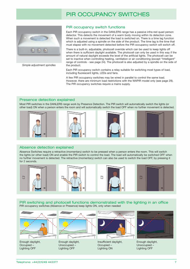
pir occupancy switch functionsEach PIR occupancy switch in the DANLERS range has a passive infra-red quad person detector. This detects the movement of a warm body moving within its detection zone. When such a movement is detected the load is switched on. There is a time lag function which is adjusted using a spindle on the side of the product. The time lag is the time that must elapse with no movement detected before the PIR occupancy switch will switch off.
There is a built-in, adjustable, photocell override which can be used to keep lights off when there is sufficient daylight available. The photocell can only be used in this way if the amount of natural daylight exceeds the level of the artificial lights. The photocell can be set to inactive when controlling heating, ventilation or air conditioning (except “Intelligent” range of controls - see page 24). The photocell is also adjusted by a spindle on the side of the product.
Each PIR occupancy switch contains a relay suitable for switching most types of load, including fluorescent lights, LEDs and fans.
A few PIR occupancy switches may be wired in parallel to control the same load. However, there are minimum load restrictions with the WAPIR model only (see page 29). The PIR occupancy switches require a mains supply.
Simple adjustment spindles
pir OCCupanCy SWitCHES
telephone: +44(0)1249 443377 7
Enough daylight, Unoccupied – Lighting oFF
Enough daylight, occupied – Lighting oFF
pir switching and photocell functions demonstrated with the lighting in an officePIR occupancy switches (Absence or Presence) keep lights oN, only when needed
Enough daylight, Unoccupied – Lighting oFF
Insufficient daylight, occupied – Lighting oN
presence detection explainedMost PIR switches in the DANLERS range work by Presence Detection. The PIR switch will automatically switch the lights (or other load) oN when a person enters the room and will automatically switch the load oFF when no further movement is detected.
absence detection explainedAbsence Switches require a retractive (momentary) switch to be pressed when a person enters the room. This will switch the lights (or other load) oN and enable the PIR switch to control the load. The load will automatically be switched oFF when no further movement is detected. The retractive (momentary) switch can also be used to switch the load oFF, by pressing it for 2 seconds.
pir detector
Passive infra-red quad person detector.
adjustable time lag
Time lag adjustable in 9 steps: 10 seconds, 20 seconds, 40 seconds, 1.25 minutes, 2.5 minutes, 5 minutes, 10 minutes, 20 minutes, 40 minutes.
adjustable photocell
The "Inhibit on" photocell on most models will inhibit the lights from switching on when somebody enters an area with plenty of ambient light. However, if somebody is already occupying an area with the lights switched on, the lights will remain on while the area is occupied, regardless of any increase in the ambient light level. This is to avoid any nuisance switching off when somebody is in the middle of a task or meeting. Range 30-1000 lux (and photocell inactive), falling on the working plane.
The “Intelligent” photocell on some batten mount controls (see page 24) and ControlZAPP products (see pages 48-53) enables even greater energy savings because in its patented calibration process it learns to ignore the artificial lighting load. It is recommended the “Intelligent” batten mount controls are only used in areas with some natural daylight. Range 100-3000 lux falling on the working plane.
Loading
All standard PIR occupancy switches can switch up to: 6 amps (1500W) of resistive loads. 6 amps (1500W) of fluorescent loads. 3 amps (750W) of electronic and wire wound transformer loads. 2 amps (500W) of CFL, 2D lamps, LED Drivers and LED lamps and fittings. 1 amp (250W) of fans.
For the WAPIR model there are some minimum load requirements (details on page 29).
Wiring in parallel
A few PIR switches can be wired in parallel to control the same load.
Start-up Mode
When the mains supply is initially connected to the PIR occupancy switch it goes through its Start-up Mode. This means it switches on for about 1 minute, then switches off and enters its operating Mode. If a manual wall switch is feeding the PIR occupancy switch (see wiring diagrams on appropriate product pages) then it will go through the Start-up Mode each time the wall switch is switched on (not applicable to WAPIR, see page 29).
By wiring the manual wall switch in the alternative position, the supply to the PIR occupancy switch is uninterrupted and it remains in operating Mode. It does not go through its Start-up Mode each time the wall switch is switched on.
pir OCCupanCy SWitCH SpECiFiCatiOnS
8 www.danlers.co.uk
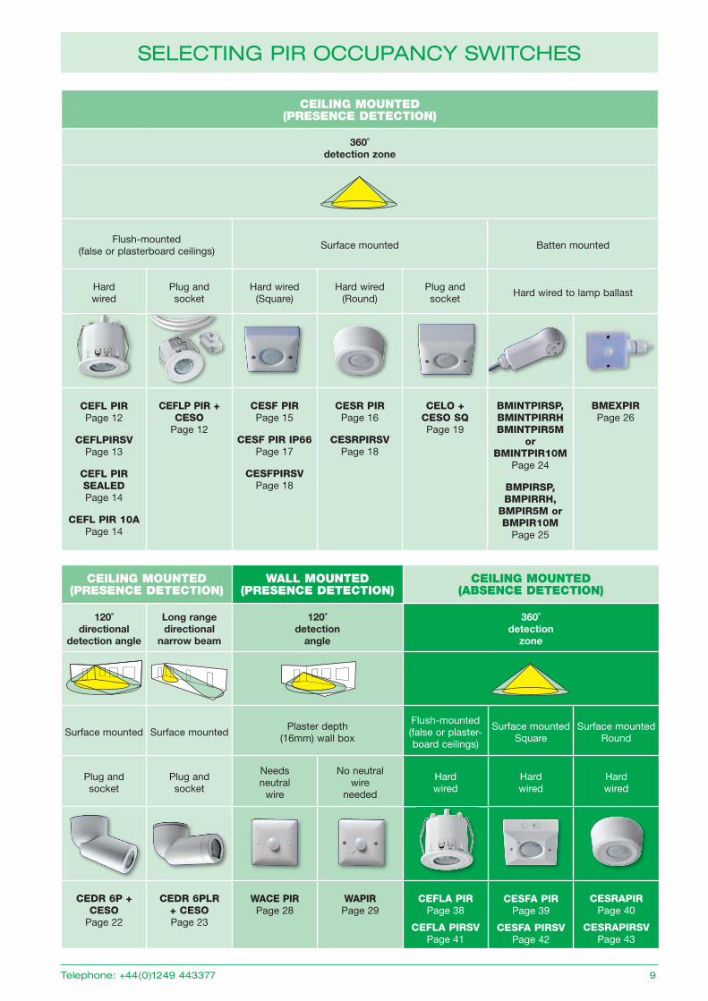
CEILING MOUNTED(PRESENCE DETECTION)
WALL MOUNTED(PRESENCE DETECTION)
CEILING MOUNTED (ABSENCE DETECTION)
120˚ directional
detection angle
Long rangedirectional
narrow beam
120˚ detection
angle
360˚ detection
zone
Surface mounted Surface mountedPlaster depth
(16mm) wall box
Flush-mounted (false or plaster-board ceilings)
Surface mountedSquare
Surface mountedRound
Plug andsocket
Plug andsocket
Needsneutral
wire
No neutralwire
needed
Hard wired
Hard wired
Hard wired
CEDR 6P + CESO
Page 22
CEDR 6PLR + CESOPage 23
WACE PIRPage 28
WAPIRPage 29
CEFLA PIRPage 38
CEFLA PIRSVPage 41
CESFA PIRPage 39
CESFA PIRSVPage 42
CESRAPIRPage 40
CESRAPIRSVPage 43
SELECting pir OCCupanCy SWitCHES
telephone: +44(0)1249 443377 9
CEILING MOUNTED (PRESENCE DETECTION)
360˚ detection zone
Flush-mounted (false or plasterboard ceilings)
Surface mounted Batten mounted
Hard wired
Plug andsocket
Hard wired(Square)
Hard wired(Round)
Plug andsocket
Hard wired to lamp ballast
CEFL PIRPage 12
CEFLPIRSVPage 13
CEFL PIRSEALEDPage 14
CEFL PIR 10APage 14
CEFLP PIR + CESO
Page 12
CESF PIRPage 15
CESF PIR IP66Page 17
CESFPIRSVPage 18
CESR PIRPage 16
CESRPIRSVPage 18
CELO + CESO SQPage 19
BMINTPIRSP,BMINTPIRRH BMINTPIR5M
or BMINTPIR10M
Page 24
BMPIRSP,BMPIRRH,
BMPIR5M or BMPIR10M
Page 25
BMEXPIRPage 26
MEETINg RooM oFFICE
oFFICE
oFFICE
CoRRIDoR
oPEN PLAN oFFICES
RECEPTIoN
STAIRWELL
ToILETS
FACToRy AREA
HIgH BAy RACKINg
RESTRooM
oP
EN
S
TAIR
CA
SE
HIgH BAy RACKINg
SHoWER RooM
ToILET LoBBy
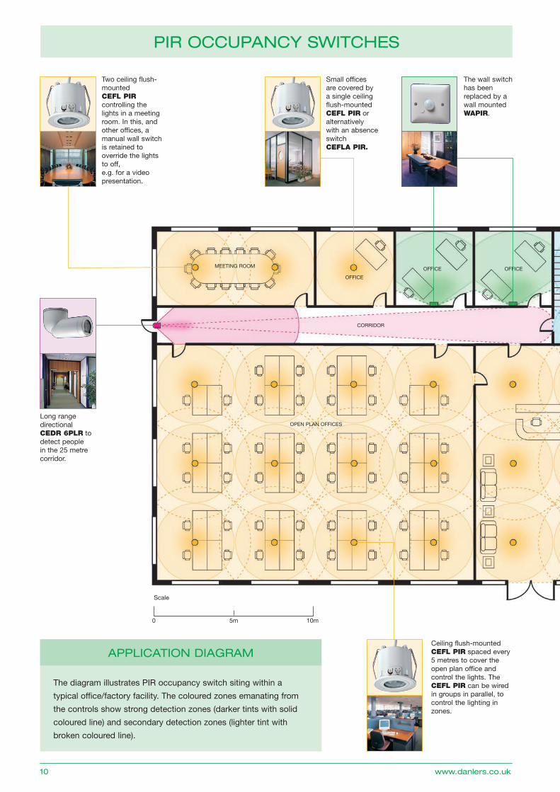
appLiCatiOn diagraM
5m 10m0
Scale
Ceiling flush-mounted CEFL PIR spaced every 5 metres to cover the open plan office and control the lights. The CEFL PIR can be wired in groups in parallel, to control the lighting in zones.
Long range directional CEDR 6PLR to detect people in the 25 metre corridor.
Two ceiling flush-mounted CEFL PIR controlling the lights in a meeting room. In this, and other offices, a manual wall switch is retained to override the lights to off, e.g. for a video presentation.
Small offices are covered by a single ceiling flush-mounted CEFL PIR or alternatively with an absence switch CEFLA PIR.
The wall switch has been replaced by a wall mounted WAPIR.
pir OCCupanCy SWitCHES
The diagram illustrates PIR occupancy switch siting within a
typical office/factory facility. The coloured zones emanating from
the controls show strong detection zones (darker tints with solid
coloured line) and secondary detection zones (lighter tint with
broken coloured line).
10 www.danlers.co.uk
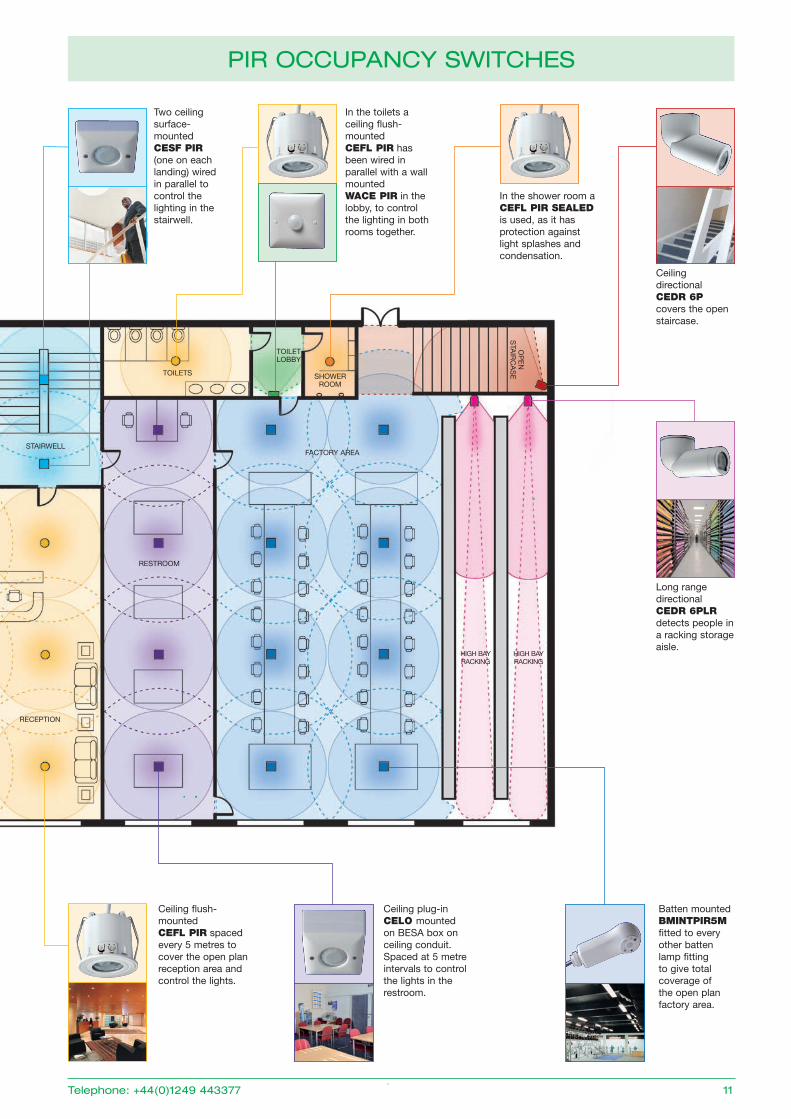
Long range directional CEDR 6PLR detects people in a racking storage aisle.
Batten mounted BMINTPIR5M fitted to every other batten lamp fitting to give total coverage of the open plan factory area.
Ceiling flush-mounted CEFL PIR spaced every 5 metres to cover the open plan reception area and control the lights.
Ceiling plug-in CELO mounted on BESA box on ceiling conduit. Spaced at 5 metre intervals to control the lights in the restroom.
In the shower room a CEFL PIR SEALED is used, as it has protection against light splashes and condensation.
In the toilets a ceiling flush- mounted CEFL PIR has been wired in parallel with a wall mounted WACE PIR in the lobby, to control the lighting in both rooms together.
Two ceiling surface- mounted CESF PIR (one on each landing) wired in parallel to control the lighting in the stairwell.
Ceiling directional CEDR 6P covers the open staircase.
MEETINg RooM oFFICE
oFFICE
oFFICE
CoRRIDoR
oPEN PLAN oFFICES
RECEPTIoN
STAIRWELL
ToILETS
FACToRy AREA
HIgH BAy RACKINg
RESTRooM
oP
EN
S
TAIR
CA
SE
HIgH BAy RACKINg
SHoWER RooM
ToILET LoBBy
pir OCCupanCy SWitCHES
telephone: +44(0)1249 443377 11
pir OCCupanCy SWitCHES
Plug and socket version: CEFLPPIR
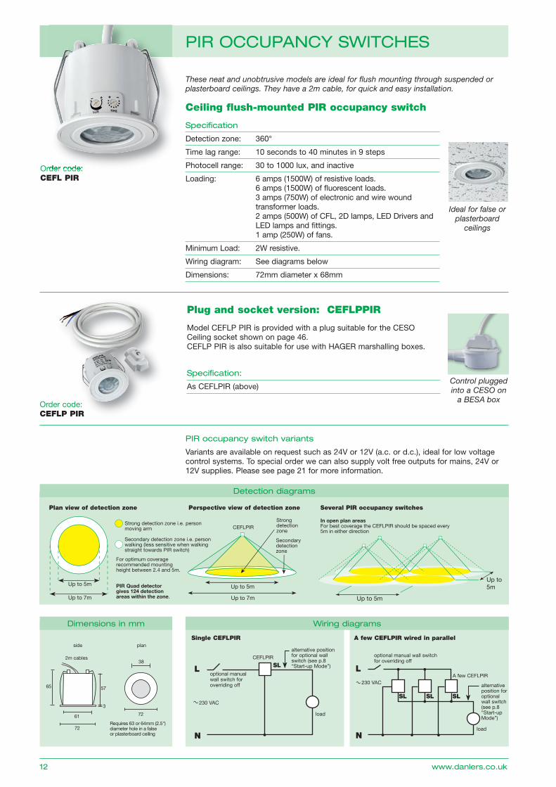
Model CEFLP PIR is provided with a plug suitable for the CESo Ceiling socket shown on page 46.CEFLP PIR is also suitable for use with HAgER marshalling boxes.
Specification:
As CEFLPIR (above)Control plugged into a CESO on
a BESA box
These neat and unobtrusive models are ideal for flush mounting through suspended or plasterboard ceilings. They have a 2m cable, for quick and easy installation.
order code: CEFL PIR
Ceiling flush-mounted PIR occupancy switch
Specification
Detection zone: 360°
Time lag range: 10 seconds to 40 minutes in 9 steps
Photocell range: 30 to 1000 lux, and inactive
Loading: 6 amps (1500W) of resistive loads. 6 amps (1500W) of fl uorescent loads. 3 amps (750W) of electronic and wire wound transformer loads. 2 amps (500W) of CFL, 2D lamps, LED Drivers and LED lamps and fi ttings. 1 amp (250W) of fans.
Minimum Load: 2W resistive.
Wiring diagram: See diagrams below
Dimensions: 72mm diameter x 68mm
NN
Fig. 201 Ceiling mounted PIR occupancy switch
Up to 5m
Up to 7m
Up to 5m
Up to 7m
Up to 5m
Up to5m
In open plan areasFor best coverage the CEFLPIR should be spaced every 5m in either direction
CEFLPIRStrong detection zone
Secondary detection zone
Strong detection zone i.e. person moving arm
Secondary detection zone i.e. person walking (less sensitive when walking straight towards PIR switch)
For optimum coverage recommended mounting height between 2.4 and 5m.
PIR Quad detector gives 124 detection areas within the zone.
Plan view of detection zone Several PIR occupancy switchesPerspective view of detection zone
L
load
optional manual wall switch for overriding off
A few CEFLPIR230 VAC
L
load
CEFLPIR
optional manual wall switch for overriding off
Single CEFLPIR
230 VAC
alternative position for optional wall switch (see p.8 “Start-up Mode”)
A few CEFLPIR wired in parallel
alternativeposition for optional wall switch (see p.8 “Start-up Mode”)
Ideal for false or plasterboard
ceilings
65
61
72
72
plan
57
3
2m cables
side
38
Requires 63 or 64mm (2.5") diameter hole in a false or plasterboard ceiling
pir occupancy switch variants
Variants are available on request such as 24V or 12V (a.c. or d.c.), ideal for low voltage control systems. To special order we can also supply volt free outputs for mains, 24V or 12V supplies. Please see page 21 for more information.
SL
SL SL SL
detection diagrams
dimensions in mm Wiring diagrams
order code:
12 www.danlers.co.uk
order code: CEFLP PIR
telephone: +44(0)1249 443377 13
pir OCCupanCy SWitCHES
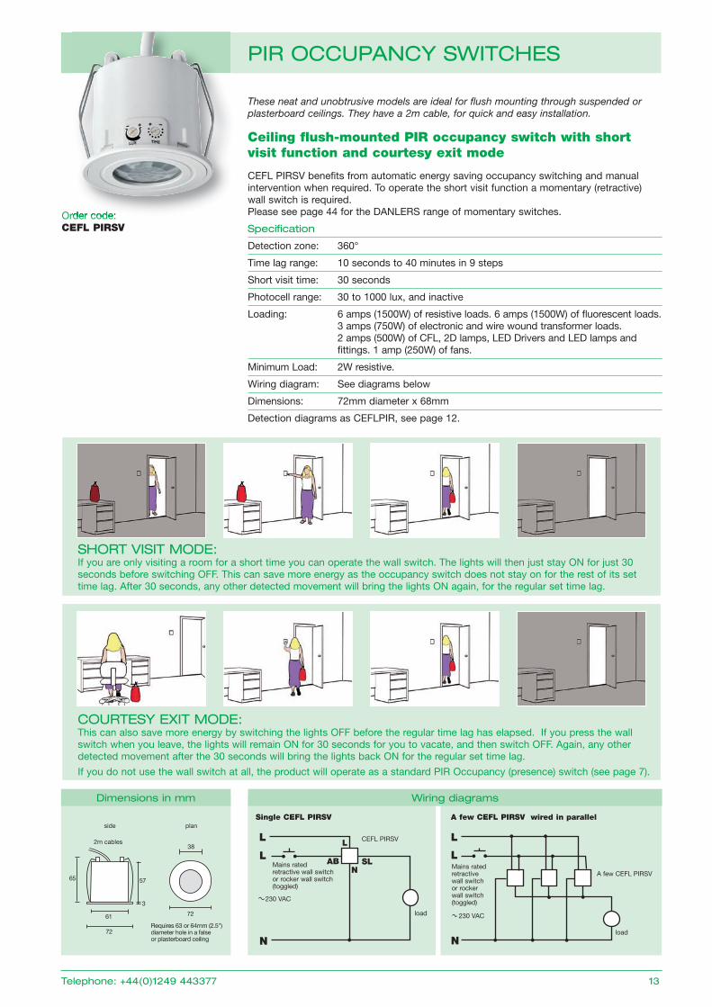
These neat and unobtrusive models are ideal for flush mounting through suspended or plasterboard ceilings. They have a 2m cable, for quick and easy installation.
order code: CEFL PIRSV
65
61
72
72
plan
57
3
2m cables
side
38
Requires 63 or 64mm (2.5") diameter hole in a false or plasterboard ceiling
dimensions in mm
order code:
Ceiling flush-mounted PIR occupancy switch with short visit function and courtesy exit mode
CEFL PIRSV benefits from automatic energy saving occupancy switching and manual intervention when required. To operate the short visit function a momentary (retractive) wall switch is required. Please see page 44 for the DANLERS range of momentary switches.
Specification
Detection zone: 360°
Time lag range: 10 seconds to 40 minutes in 9 steps
Short visit time: 30 seconds
Photocell range: 30 to 1000 lux, and inactive
Loading: 6 amps (1500W) of resistive loads. 6 amps (1500W) of fl uorescent loads. 3 amps (750W) of electronic and wire wound transformer loads. 2 amps (500W) of CFL, 2D lamps, LED Drivers and LED lamps and fi ttings. 1 amp (250W) of fans.
Minimum Load: 2W resistive.
Wiring diagram: See diagrams below
Dimensions: 72mm diameter x 68mm
Detection diagrams as CEFLPIR, see page 12.
SHOrt viSit MOdE: If you are only visiting a room for a short time you can operate the wall switch. The lights will then just stay oN for just 30 seconds before switching oFF. This can save more energy as the occupancy switch does not stay on for the rest of its set time lag. After 30 seconds, any other detected movement will bring the lights oN again, for the regular set time lag.
COurtESy EXit MOdE: This can also save more energy by switching the lights oFF before the regular time lag has elapsed. If you press the wall switch when you leave, the lights will remain oN for 30 seconds for you to vacate, and then switch oFF. Again, any other detected movement after the 30 seconds will bring the lights back oN for the regular set time lag.
If you do not use the wall switch at all, the product will operate as a standard PIR occupancy (presence) switch (see page 7).
L
N
load
CEFL PIRSV
Single CEFL PIRSV
230 VAC
L
L
Nload
A few CEFL PIRSV
230 VAC
A few CEFL PIRSV wired in parallel
Mains rated retractive wall switch or rocker wall switch (toggled)
LL
AB SLN
Mains rated retractive wall switch or rocker wall switch (toggled)
Wiring diagrams
14 www.danlers.co.uk
pir OCCupanCy SWitCHES
order code: CEFL PIR 10A
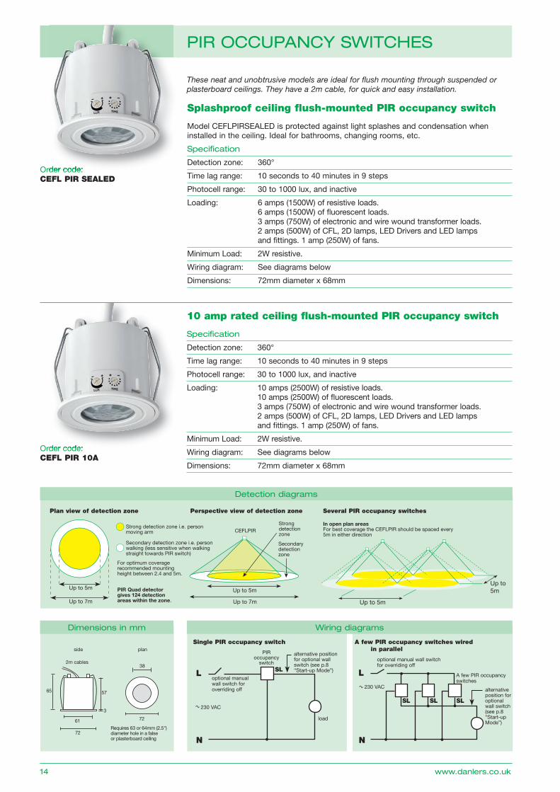
order code: CEFL PIR SEALED
Splashproof ceiling flush-mounted PIR occupancy switch
Model CEFLPIRSEALED is protected against light splashes and condensation when installed in the ceiling. Ideal for bathrooms, changing rooms, etc.
Specification
Detection zone: 360°
Time lag range: 10 seconds to 40 minutes in 9 steps
Photocell range: 30 to 1000 lux, and inactive
Loading: 6 amps (1500W) of resistive loads. 6 amps (1500W) of fl uorescent loads. 3 amps (750W) of electronic and wire wound transformer loads. 2 amps (500W) of CFL, 2D lamps, LED Drivers and LED lamps and fi ttings. 1 amp (250W) of fans.
Minimum Load: 2W resistive.
Wiring diagram: See diagrams below
Dimensions: 72mm diameter x 68mm
10 amp rated ceiling flush-mounted PIR occupancy switch
Specification
Detection zone: 360°
Time lag range: 10 seconds to 40 minutes in 9 steps
Photocell range: 30 to 1000 lux, and inactive
Loading: 10 amps (2500W) of resistive loads. 10 amps (2500W) of fl uorescent loads. 3 amps (750W) of electronic and wire wound transformer loads. 2 amps (500W) of CFL, 2D lamps, LED Drivers and LED lamps and fi ttings. 1 amp (250W) of fans.
Minimum Load: 2W resistive.
Wiring diagram: See diagrams below
Dimensions: 72mm diameter x 68mm
Fig. 201 Ceiling mounted PIR occupancy switch
Up to 5m
Up to 7m
Up to 5m
Up to 7m
Up to 5m
Up to5m
In open plan areasFor best coverage the CEFLPIR should be spaced every 5m in either direction
CEFLPIRStrong detection zone
Secondary detection zone
Strong detection zone i.e. person moving arm
Secondary detection zone i.e. person walking (less sensitive when walking straight towards PIR switch)
For optimum coverage recommended mounting height between 2.4 and 5m.
PIR Quad detector gives 124 detection areas within the zone.
Plan view of detection zone Several PIR occupancy switchesPerspective view of detection zone
L
optional manual wall switch for overriding off
A few PIR occupancy switches
230 VAC
L
load
PIR occupancy
switch
optional manual wall switch for overriding off
Single PIR occupancy switch
230 VAC
alternative position for optional wall switch (see p.8 “Start-up Mode”)
A few PIR occupancy switches wired in parallel
alternativeposition for optional wall switch (see p.8 “Start-up Mode”)
These neat and unobtrusive models are ideal for flush mounting through suspended or plasterboard ceilings. They have a 2m cable, for quick and easy installation.
N
SL SL SL
SL
N
detection diagrams
dimensions in mm Wiring diagrams
65
61
72
72
plan
57
3
2m cables
side
38
Requires 63 or 64mm (2.5") diameter hole in a false or plasterboard ceiling
order code:
order code:
telephone: +44(0)1249 443377 15
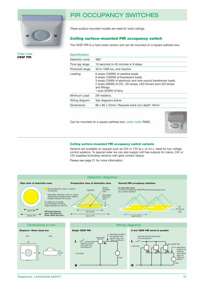
These surface-mounted models are ideal for solid ceilings.
Can be mounted on a square pattress box, order code: PABo.
order code: CESF PIR
Ceiling surface-mounted PIR occupancy switch
The CESF PIR is a hard wired version and can be mounted on a square pattress box.
Specification
Detection zone: 360°
Time lag range: 10 seconds to 40 minutes in 9 steps
Photocell range: 30 to 1000 lux, and inactive
Loading: 6 amps (1500W) of resistive loads. 6 amps (1500W) of fl uorescent loads. 3 amps (750W) of electronic and wire wound transformer loads. 2 amps (500W) of CFL, 2D lamps, LED Drivers and LED lamps and fi ttings. 1 amp (250W) of fans.
Minimum Load: 2W resistive.
Wiring diagram: See diagrams below
Dimensions: 86 x 86 x 22mm. Requires back box depth 16mm
L
Nload
A few CESF PIR230 VAC
L
N
load
CESF PIR
optional manual wall switch for overriding off
Single CESF PIR
230 VAC
A few CESF PIR wired in parallel
Fig. 201 Ceiling mounted PIR occupancy switch
Up to 5m
Up to 7m
Up to 5m
Up to 7m
Up to 5m
Up to5m
In open plan areasFor best coverage the CESFPIR should be spaced every 5m in either direction
CESFPIRStrong detection zone
Secondary detection zone
Strong detection zone i.e. person moving arm
Secondary detection zone i.e. person walking (less sensitive when walking straight towards PIR switch)
For optimum coverage recommended mounting height between 2.4 and 5m.
PIR Quad detector gives 124 detection areas within the zone.
Plan view of detection zone Several PIR occupancy switchesPerspective view of detection zone
plan side
22
86
86
alternative position for optional wall switch (see p.18 “Start-up Mode”)
alternativeposition for optional wall switch (see p.8 “Start-up Mode”)
optional manual wall switch for overriding off
Requires 16mm deep box
Ceiling surface-mounted PIR occupancy switch variants
Variants are available on request such as 24V or 12V (a.c. or d.c.), ideal for low voltage control systems. To special order we can also supply volt free outputs for mains, 24V or 12V supplies (including versions with gold contact relays).
Please see page 21 for more information.
SL SL SL
SL
dimensions in mm Wiring diagrams
detection diagrams
pir OCCupanCy SWitCHES
16 www.danlers.co.uk
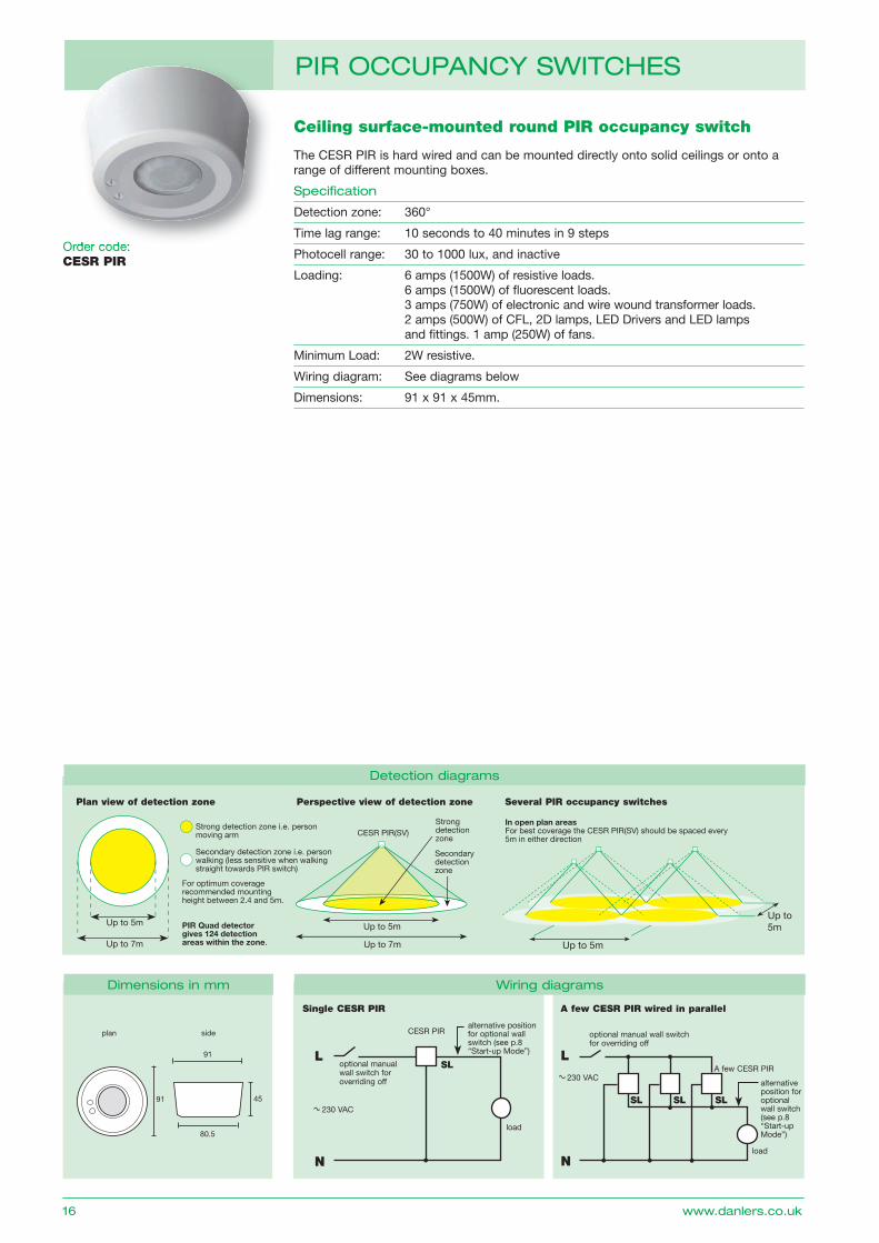
Ceiling surface-mounted round PIR occupancy switch
The CESR PIR is hard wired and can be mounted directly onto solid ceilings or onto a range of different mounting boxes.
Specification
Detection zone: 360°
Time lag range: 10 seconds to 40 minutes in 9 steps
Photocell range: 30 to 1000 lux, and inactive
Loading: 6 amps (1500W) of resistive loads. 6 amps (1500W) of fl uorescent loads. 3 amps (750W) of electronic and wire wound transformer loads. 2 amps (500W) of CFL, 2D lamps, LED Drivers and LED lamps and fi ttings. 1 amp (250W) of fans.
Minimum Load: 2W resistive.
Wiring diagram: See diagrams below
Dimensions: 91 x 91 x 45mm.
L
Nload
A few CESR PIR230 VAC
L
N
load
CESR PIR
optional manual wall switch for overriding off
Single CESR PIR
230 VAC
A few CESR PIR wired in parallel
Fig. 201 Ceiling mounted PIR occupancy switch
Up to 5m
Up to 7m
Up to 5m
Up to 7m
Up to 5m
Up to5m
In open plan areasFor best coverage the CESR PIR(SV) should be spaced every 5m in either direction
CESR PIR(SV)Strong detection zone
Secondary detection zone
Strong detection zone i.e. person moving arm
Secondary detection zone i.e. person walking (less sensitive when walking straight towards PIR switch)
For optimum coverage recommended mounting height between 2.4 and 5m.
PIR Quad detector gives 124 detection areas within the zone.
Plan view of detection zone Several PIR occupancy switchesPerspective view of detection zone
alternative position for optional wall switch (see p.8 “Start-up Mode”)
alternativeposition for optional wall switch (see p.8 “Start-up Mode”)
optional manual wall switch for overriding off
SL SL SL
SL
plan side
45
91
91
80.5
dimensions in mm Wiring diagrams
detection diagrams
pir OCCupanCy SWitCHES
order code: CESR PIRorder code:
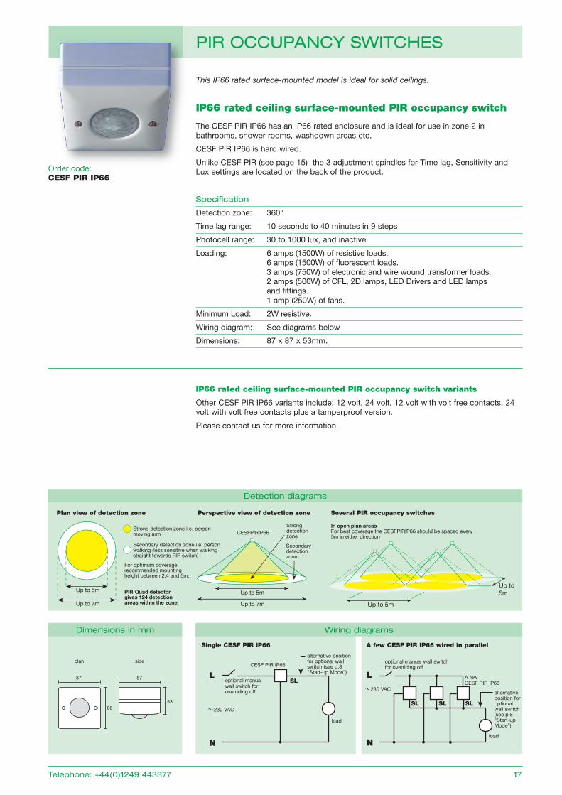
This IP66 rated surface-mounted model is ideal for solid ceilings.
order code: CESF PIR IP66
IP66 rated ceiling surface-mounted PIR occupancy switch
The CESF PIR IP66 has an IP66 rated enclosure and is ideal for use in zone 2 in bathrooms, shower rooms, washdown areas etc.
CESF PIR IP66 is hard wired.
Unlike CESF PIR (see page 15) the 3 adjustment spindles for Time lag, Sensitivity and Lux settings are located on the back of the product.
Specification
Detection zone: 360°
Time lag range: 10 seconds to 40 minutes in 9 steps
Photocell range: 30 to 1000 lux, and inactive
Loading: 6 amps (1500W) of resistive loads. 6 amps (1500W) of fl uorescent loads. 3 amps (750W) of electronic and wire wound transformer loads. 2 amps (500W) of CFL, 2D lamps, LED Drivers and LED lamps and fi ttings. 1 amp (250W) of fans.
Minimum Load: 2W resistive.
Wiring diagram: See diagrams below
Dimensions: 87 x 87 x 53mm.
IP66 rated ceiling surface-mounted PIR occupancy switch variants
other CESF PIR IP66 variants include: 12 volt, 24 volt, 12 volt with volt free contacts, 24 volt with volt free contacts plus a tamperproof version.
Please contact us for more information.
L
Nload
A few CESF PIR IP66
230 VAC
L
N
load
CESF PIR IP66
optional manual wall switch for overriding off
Single CESF PIR IP66
230 VAC
A few CESF PIR IP66 wired in parallel
Fig. 201 Ceiling mounted PIR occupancy switch
Up to 5m
Up to 7m
Up to 5m
Up to 7m
Up to 5m
Up to5m
In open plan areasFor best coverage the CESFPIRIP66 should be spaced every 5m in either direction
CESFPIRIP66Strong detection zone
Secondary detection zone
Strong detection zone i.e. person moving arm
Secondary detection zone i.e. person walking (less sensitive when walking straight towards PIR switch)
For optimum coverage recommended mounting height between 2.4 and 5m.
PIR Quad detector gives 124 detection areas within the zone.
Plan view of detection zone Several PIR occupancy switchesPerspective view of detection zone
alternative position for optional wall switch (see p.8 “Start-up Mode”)
alternativeposition for optional wall switch (see p.8 “Start-up Mode”)
optional manual wall switch for overriding off
SL SL SL
SL
dimensions in mm Wiring diagrams
detection diagrams
plan side
53
87
86
87
pir OCCupanCy SWitCHES
order code:
telephone: +44(0)1249 443377 17
18 www.danlers.co.uk
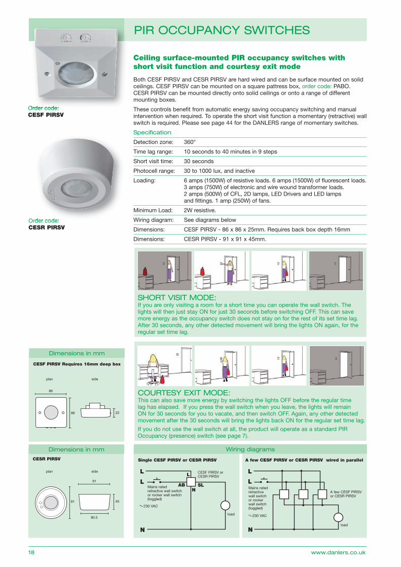
order code: CESF PIRSV
Ceiling surface-mounted PIR occupancy switches with short visit function and courtesy exit mode
Both CESF PIRSV and CESR PIRSV are hard wired and can be surface mounted on solid ceilings. CESF PIRSV can be mounted on a square pattress box, order code: PABo. CESR PIRSV can be mounted directly onto solid ceilings or onto a range of different mounting boxes.
These controls benefit from automatic energy saving occupancy switching and manual intervention when required. To operate the short visit function a momentary (retractive) wall switch is required. Please see page 44 for the DANLERS range of momentary switches.
Specification
Detection zone: 360°
Time lag range: 10 seconds to 40 minutes in 9 steps
Short visit time: 30 seconds
Photocell range: 30 to 1000 lux, and inactive
Loading: 6 amps (1500W) of resistive loads. 6 amps (1500W) of fl uorescent loads. 3 amps (750W) of electronic and wire wound transformer loads. 2 amps (500W) of CFL, 2D lamps, LED Drivers and LED lamps and fi ttings. 1 amp (250W) of fans.
Minimum Load: 2W resistive.
Wiring diagram: See diagrams below
Dimensions: CESF PIRSV - 86 x 86 x 25mm. Requires back box depth 16mm
Dimensions: CESR PIRSV - 91 x 91 x 45mm.
plan side
22
86
86
CESF PIRSV Requires 16mm deep box
dimensions in mm
pir OCCupanCy SWitCHES
order code:
L
N
load
CESF PIRSV orCESR PIRSV
Single CESF PIRSV or CESR PIRSV
230 VAC
L
L
Nload
A few CESF PIRSV or CESR PIRSV
230 VAC
A few CESF PIRSV or CESR PIRSV wired in parallel
Mains rated retractive wall switch or rocker wall switch (toggled)
LL
AB SLN
Mains rated retractive wall switch or rocker wall switch (toggled)
Wiring diagrams
order code: CESR PIRSVorder code:
SHOrt viSit MOdE: If you are only visiting a room for a short time you can operate the wall switch. The lights will then just stay oN for just 30 seconds before switching oFF. This can save more energy as the occupancy switch does not stay on for the rest of its set time lag. After 30 seconds, any other detected movement will bring the lights oN again, for the regular set time lag.
COurtESy EXit MOdE: This can also save more energy by switching the lights oFF before the regular time lag has elapsed. If you press the wall switch when you leave, the lights will remain oN for 30 seconds for you to vacate, and then switch oFF. Again, any other detected movement after the 30 seconds will bring the lights back oN for the regular set time lag.
If you do not use the wall switch at all, the product will operate as a standard PIR occupancy (presence) switch (see page 7).
plan side
45
91
91
80.5
dimensions in mm
CESR PIRSV
telephone: +44(0)1249 443377 19
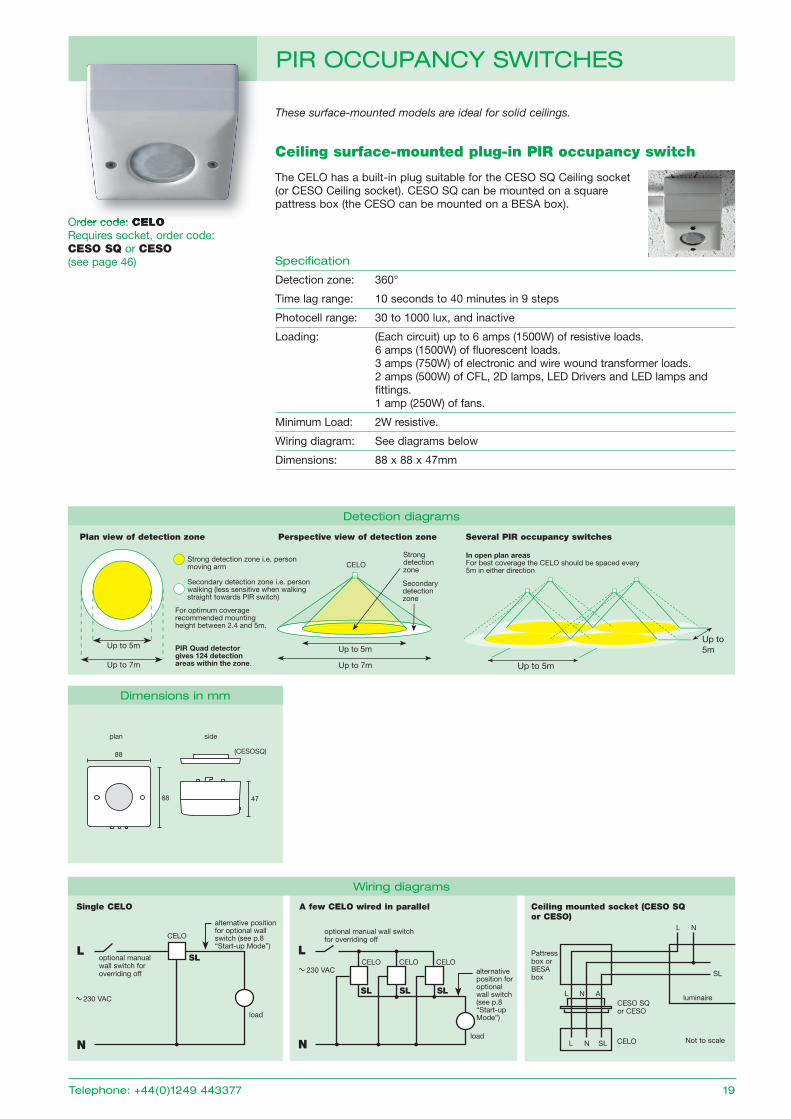
These surface-mounted models are ideal for solid ceilings.
order code: CELORequires socket, order code:CESO SQ or CESO(see page 46)
Ceiling surface-mounted plug-in PIR occupancy switch
The CELo has a built-in plug suitable for the CESo SQ Ceiling socket (or CESo Ceiling socket). CESo SQ can be mounted on a square pattress box (the CESo can be mounted on a BESA box).
Specification
Detection zone: 360°
Time lag range: 10 seconds to 40 minutes in 9 steps
Photocell range: 30 to 1000 lux, and inactive
Loading: (Each circuit) up to 6 amps (1500W) of resistive loads. 6 amps (1500W) of fl uorescent loads. 3 amps (750W) of electronic and wire wound transformer loads. 2 amps (500W) of CFL, 2D lamps, LED Drivers and LED lamps and fi ttings. 1 amp (250W) of fans.
Minimum Load: 2W resistive.
Wiring diagram: See diagrams below
Dimensions: 88 x 88 x 47mm
L
load
optional manual wall switch for overriding off
CELoCELoCELo230 VAC
Single CELO A few CELO wired in parallel Ceiling mounted socket (CESO SQ or CESO)
L N SL CELo Not to scale
CESo SQor CESo
Pattress box orBESA box
luminaire
L N
SL
N
L
load
CELo
optional manual wall switch for overriding off
230 VAC
N
plan side
47
88
88
(CESOSQ)
alternativeposition for optional wall switch (see p.8 “Start-up Mode”)
alternative position for optional wall switch (see p.8 “Start-up Mode”)
Up to 5m
Up to 7m
Up to 5m
Up to 7m Up to 5m
Up to5m
In open plan areasFor best coverage the CELO should be spaced every 5m in either direction
CELOStrong detection zone
Secondary detection zone
Strong detection zone i.e. person moving arm
Secondary detection zone i.e. person walking (less sensitive when walking straight towards PIR switch)
For optimum coverage recommended mounting height between 2.4 and 5m.
PIR Quad detector gives 124 detection areas within the zone.
Plan view of detection zone Several PIR occupancy switchesPerspective view of detection zone
L N ASL SL SL
SL
detection diagrams
dimensions in mm
Wiring diagrams
pir OCCupanCy SWitCHES
order code: CELO
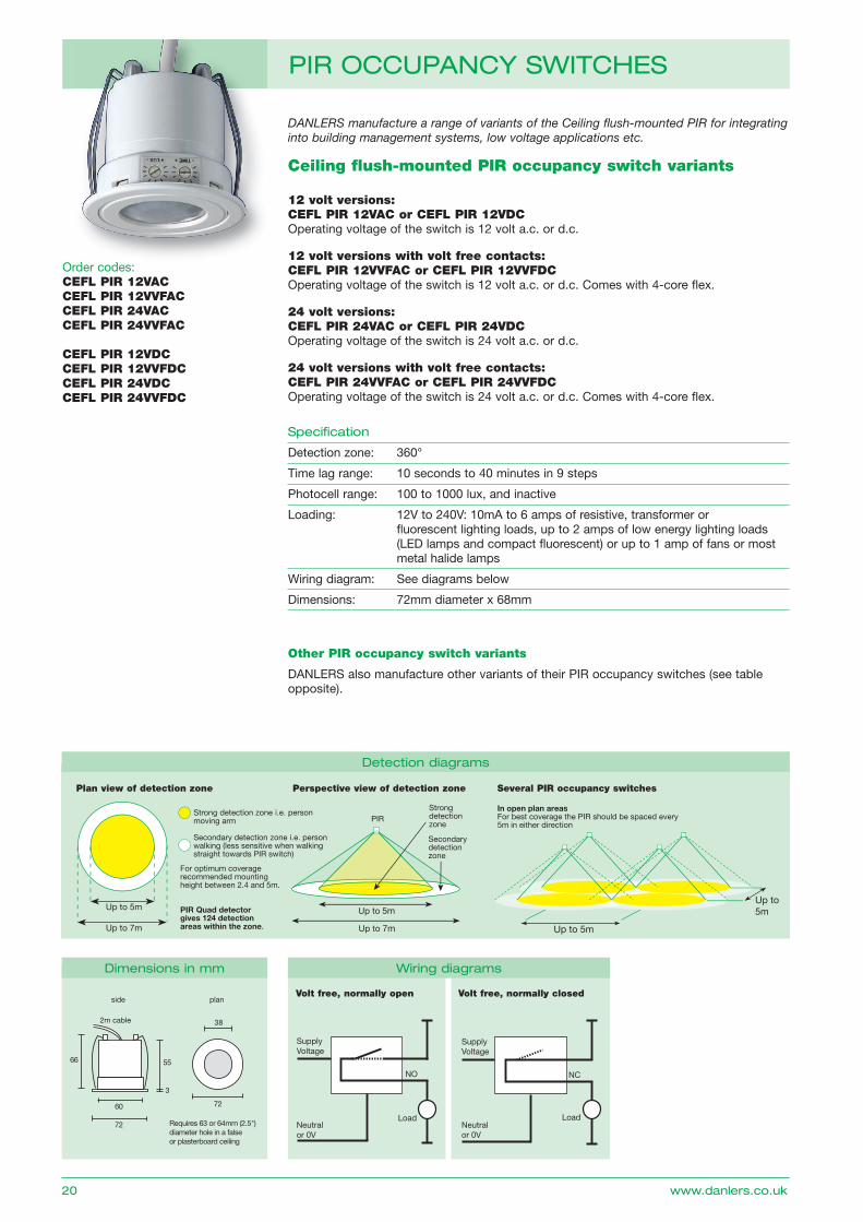
DANLERS manufacture a range of variants of the Ceiling flush-mounted PIR for integrating into building management systems, low voltage applications etc.
order codes: CEFL PIR 12VAC CEFL PIR 12VVFACCEFL PIR 24VAC CEFL PIR 24VVFAC
CEFL PIR 12VDC CEFL PIR 12VVFDCCEFL PIR 24VDC CEFL PIR 24VVFDC
Ceiling flush-mounted PIR occupancy switch variants
12 volt versions: CEFL PIR 12VAC or CEFL PIR 12VDCoperating voltage of the switch is 12 volt a.c. or d.c.
12 volt versions with volt free contacts: CEFL PIR 12VVFAC or CEFL PIR 12VVFDCoperating voltage of the switch is 12 volt a.c. or d.c. Comes with 4-core flex.
24 volt versions: CEFL PIR 24VAC or CEFL PIR 24VDCoperating voltage of the switch is 24 volt a.c. or d.c.
24 volt versions with volt free contacts: CEFL PIR 24VVFAC or CEFL PIR 24VVFDCoperating voltage of the switch is 24 volt a.c. or d.c. Comes with 4-core flex.
Specification
Detection zone: 360°
Time lag range: 10 seconds to 40 minutes in 9 steps
Photocell range: 100 to 1000 lux, and inactive
Loading: 12V to 240V: 10mA to 6 amps of resistive, transformer or fluorescent lighting loads, up to 2 amps of low energy lighting loads (LED lamps and compact fluorescent) or up to 1 amp of fans or most metal halide lamps
Wiring diagram: See diagrams below
Dimensions: 72mm diameter x 68mm
Other PIR occupancy switch variants
DANLERS also manufacture other variants of their PIR occupancy switches (see table opposite).
Fig. 201 Ceiling mounted PIR occupancy switch
Up to 5m
Up to 7m
Up to 5m
Up to 7m
Up to 5m
Up to5m
In open plan areasFor best coverage the PIR should be spaced every 5m in either direction
PIRStrong detection zone
Secondary detection zone
Strong detection zone i.e. person moving arm
Secondary detection zone i.e. person walking (less sensitive when walking straight towards PIR switch)
For optimum coverage recommended mounting height between 2.4 and 5m.
PIR Quad detector gives 124 detection areas within the zone.
Plan view of detection zone Several PIR occupancy switchesPerspective view of detection zone
55
3
2m cable
60
72
72
side plan
66
Requires 63 or 64mm (2.5") diameter hole in a false or plasterboard ceiling
38
Volt free, normally open Volt free, normally closed
Volt Free, Normally Open
SupplyVoltage
Neutralor 0V
NO
Load
Volt Free, Normally Closed
SupplyVoltage
Neutralor 0V
NC
Load
SupplyVoltage
Neutralor 0V
Volt Free, Change Over
C
NO
NC
Load(s)
detection diagrams
dimensions in mm Wiring diagrams
20 www.danlers.co.uk
pir OCCupanCy SWitCHES
order codes:
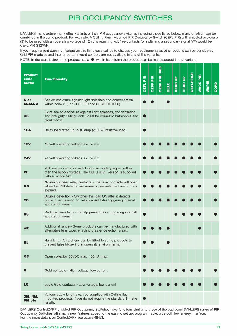
DANLERS manufacture many other variants of their PIR occupancy switches including those listed below, many of which can be combined in the same product. For example: A Ceiling Flush Mounted PIR occupancy Switch (CEFL PIR) with a sealed enclosure (S) to be used with an operating voltage of 12 volts requiring volt free contacts for switching a secondary signal (VF) would be CEFL PIR S12VVF.
If your requirement does not feature on this list please call us to discuss your requirements as other options can be considered. grid PIR modules and Interior batten mount controls are not available in any of the variants.
NoTE: In the table below if the product has a within its column the product can be manufactured in that variant.
Product code Suffix
Functionality
CE
FL P
IR
CE
SF P
IR
CE
SF P
IR I
P66
CE
LO
CE
DR
6P
CE
DR
6P
CE
FLP
IRLR
WA
CE
PIR
WA
PIR
CO
PD
S or SEALED
Sealed enclosure against light splashes and condensation within zone 2. (For CESF PIR see CESF PIR IP66).
XSExtra sealed enclosure against light splashes, condensation and draughty ceiling voids. Ideal for domestic bathrooms and cloakrooms.
10A Relay load rated up to 10 amp (2500W) resistive load.
12V 12 volt operating voltage a.c. or d.c.
24V 24 volt operating voltage a.c. or d.c.
VFVolt free contacts for switching a secondary signal, rather than the supply voltage. The CEFLPIRVF version is supplied with a 5-core flex.
NCNormally closed relay contacts - The relay contacts will open when the PIR detects and remain open until the time lag has expired.
2DDouble detection - Switches the load oN after it detects twice in succession, to help prevent false triggering in small application areas.
RS Reduced sensitivity - to help prevent false triggering in small application areas.
AR Additional range - Some products can be manufactured with alternative lens types enabling greater detection areas.
HL Hard lens - A hard lens can be fitted to some products to prevent false triggering in draughty environments.
OC open collector, 30VDC max, 100mA max
G gold contacts - High voltage, low current
LG Logic gold contacts - Low voltage, low current
3M, 4M, 5M etc
Various cable lengths can be supplied with Ceiling flush mounted products if you do not require the standard 2 metre length.
DANLERS ControlZAPP enabled PIR occupancy Switches have functions similar to those of the traditional DANLERS range of PIR occupancy Switches with many new features added to the easy to set up, programmable, bluetooth low energy interface. For the more details on ControlZAPP see pages 48-53.
telephone: +44(0)1249 443377 21
pir OCCupanCy SWitCHES
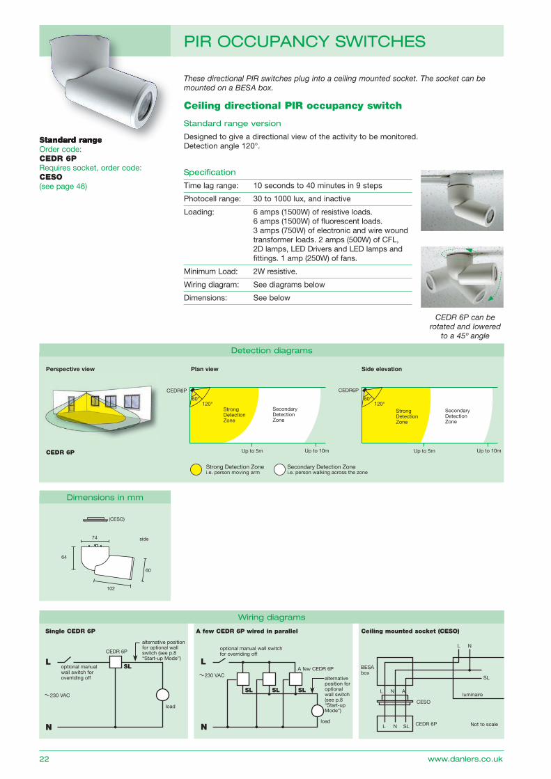
Standard rangeorder code:CEDR 6PRequires socket, order code: CESO(see page 46)
Ceiling directional PIR occupancy switch
Standard range version
Designed to give a directional view of the activity to be monitored. Detection angle 120°.
Specification
Time lag range: 10 seconds to 40 minutes in 9 steps
Photocell range: 30 to 1000 lux, and inactive
Loading: 6 amps (1500W) of resistive loads. 6 amps (1500W) of fl uorescent loads. 3 amps (750W) of electronic and wire wound transformer loads. 2 amps (500W) of CFL, 2D lamps, LED Drivers and LED lamps and fi ttings. 1 amp (250W) of fans.
Minimum Load: 2W resistive.
Wiring diagram: See diagrams below
Dimensions: See below
CEDR 6P can be rotated and lowered
to a 45º angle
These directional PIR switches plug into a ceiling mounted socket. The socket can be mounted on a BESA box.
L
load
optional manual wall switch for overriding off
A few CEDR 6P230 VAC
L
load
CEDR 6P
optional manual wall switch for overriding off
Single CEDR 6P
230 VAC
A few CEDR 6P wired in parallel Ceiling mounted socket (CESO)
Up to 5m Up to 10m
Strong Detection Zone
Secondary Detection Zone
60° 120°
CEDR6P
Up to 5m Up to 10m
Strong Detection Zone
Secondary Detection Zone
60° 120°
CEDR6P
Strong Detection Zonei.e. person moving arm
Secondary Detection Zonei.e. person walking across the zone
Plan view Side elevation
CEDR 6P
L N SL CEDR 6P Not to scale
CESo
BESA box
luminaire
L N
SL
NN
alternative position for optional wall switch (see p.8 “Start-up Mode”)
alternativeposition for optional wall switch (see p.8 “Start-up Mode”)
60
74
64
102
side
(CESO)
Perspective view
L N ASL SL SL
SL
detection diagrams
dimensions in mm
Wiring diagrams
22 www.danlers.co.uk
pir OCCupanCy SWitCHES
Standard range
Long rangeorder code:CEDR 6PLRRequires socket, order code: CESO(see page 46)
Ceiling directional PIR occupancy switch
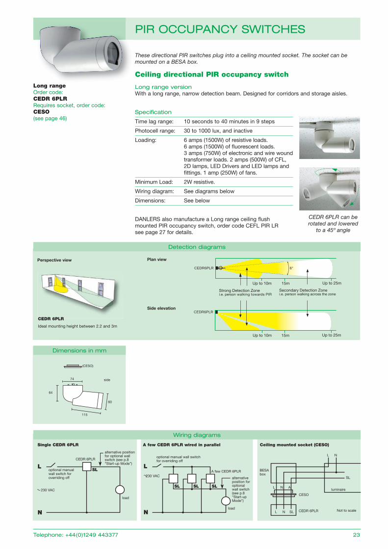
Long range versionWith a long range, narrow detection beam. Designed for corridors and storage aisles.
Specification
Time lag range: 10 seconds to 40 minutes in 9 steps
Photocell range: 30 to 1000 lux, and inactive
Loading: 6 amps (1500W) of resistive loads. 6 amps (1500W) of fl uorescent loads. 3 amps (750W) of electronic and wire wound transformer loads. 2 amps (500W) of CFL, 2D lamps, LED Drivers and LED lamps and fi ttings. 1 amp (250W) of fans.
Minimum Load: 2W resistive.
Wiring diagram: See diagrams below
Dimensions: See below
DANLERS also manufacture a Long range ceiling flush mounted PIR occupancy switch, order code CEFL PIR LR see page 27 for details.
These directional PIR switches plug into a ceiling mounted socket. The socket can be mounted on a BESA box.
L
load
optional manual wall switch for overriding off
A few CEDR 6PLR230 VAC
L
load
CEDR 6PLR
optional manual wall switch for overriding off
Single CEDR 6PLR
230 VAC
alternative position for optional wall switch (see p.8 “Start-up Mode”)
A few CEDR 6PLR wired in parallel
alternativeposition for optional wall switch (see p.8 “Start-up Mode”)
Ceiling mounted socket (CESO)
L N SL CEDR 6PLR Not to scale
CESo
BESA box
luminaire
L N
SL
Up to 25m
CEDR6PLR
Strong Detection Zonei.e. person walking towards PIR
Secondary Detection Zonei.e. person walking across the zone
Up to 10m Up to 25m
CEDR6PLR
15mUp to 10m
15m
6°
Plan view
Side elevation
CEDR 6PLR
Ideal mounting height between 2.2 and 3m
NN
60
74
64
115
side
(CESO)
CEDR 6PLR can be rotated and lowered
to a 45º angle
Perspective view
L N ASL SL SL
SL
Wiring diagrams
dimensions in mm
detection diagrams
telephone: +44(0)1249 443377 23
pir OCCupanCy SWitCHES
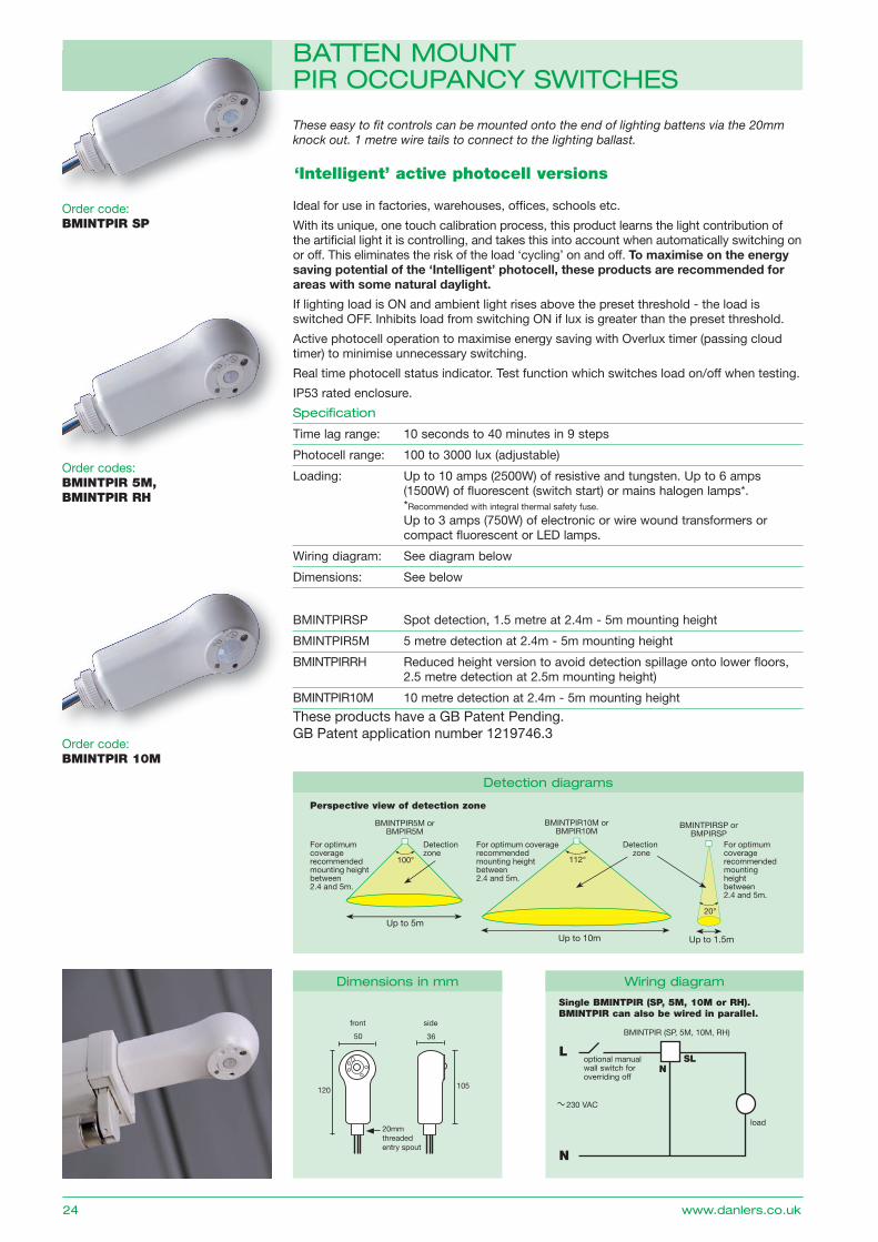
‘Intelligent’ active photocell versions
Ideal for use in factories, warehouses, offi ces, schools etc.
With its unique, one touch calibration process, this product learns the light contribution of the artifi cial light it is controlling, and takes this into account when automatically switching on or off. This eliminates the risk of the load ‘cycling’ on and off. To maximise on the energy saving potential of the ‘Intelligent’ photocell, these products are recommended for areas with some natural daylight.
If lighting load is oN and ambient light rises above the preset threshold - the load is switched oFF. Inhibits load from switching oN if lux is greater than the preset threshold.
Active photocell operation to maximise energy saving with overlux timer (passing cloud timer) to minimise unnecessary switching.
Real time photocell status indicator. Test function which switches load on/off when testing.
IP53 rated enclosure.
Specification
Time lag range: 10 seconds to 40 minutes in 9 steps
Photocell range: 100 to 3000 lux (adjustable)
Loading: Up to 10 amps (2500W) of resistive and tungsten. Up to 6 amps (1500W) of fluorescent (switch start) or mains halogen lamps*. *Recommended with integral thermal safety fuse.
Up to 3 amps (750W) of electronic or wire wound transformers or compact fluorescent or LED lamps.
Wiring diagram: See diagram below
Dimensions: See below
BMINTPIRSP Spot detection, 1.5 metre at 2.4m - 5m mounting height
BMINTPIR5M 5 metre detection at 2.4m - 5m mounting height
BMINTPIRRH Reduced height version to avoid detection spillage onto lower floors, 2.5 metre detection at 2.5m mounting height)
BMINTPIR10M 10 metre detection at 2.4m - 5m mounting height
These easy to fi t controls can be mounted onto the end of lighting battens via the 20mm knock out. 1 metre wire tails to connect to the lighting ballast.
These products have a gB Patent Pending. gB Patent application number 1219746.3
front
50
120
36
105
side
20mmthreadedentry spout
Up to 5m
BMINTPIR5M orBMPIR5M
For optimum coverage recommended mounting height between 2.4 and 5m.
Perspective view of detection zone
Detection zone
100°
Up to 10m
BMINTPIR10M orBMPIR10M
For optimum coverage recommended mounting height between 2.4 and 5m.
Detection zone
112°
Up to 1.5m
BMINTPIRSP orBMPIRSP
For optimum coverage recommended mounting height between 2.4 and 5m.
20°
dimensions in mm
detection diagrams
L
load
BMINTPIR (SP, 5M, 10M, RH)
optional manual wall switch for overriding off
Single BMINTPIR (SP, 5M, 10M or RH).BMINTPIR can also be wired in parallel.
230 VAC
N
SLN
Wiring diagram
24 www.danlers.co.uk
battEn MOunt pir OCCupanCy SWitCHES
order codes:BMINTPIR 5M,BMINTPIR RH
order code:BMINTPIR 10M
order code:BMINTPIR SP
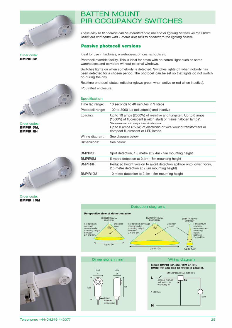
Passive photocell versions
Ideal for use in factories, warehouses, offi ces, schools etc
Photocell override facility. This is ideal for areas with no natural light such as some warehouses and corridors without external windows.
Switches lights on when somebody is detected. Switches lights off when nobody has been detected for a chosen period. The photocell can be set so that lights do not switch on during the day.
Realtime photocell status indicator (glows green when active or red when inactive).
IP53 rated enclosure.
Specification
Time lag range: 10 seconds to 40 minutes in 9 steps
Photocell range: 100 to 3000 lux (adjustable) and inactive
Loading: Up to 10 amps (2500W) of resistive and tungsten. Up to 6 amps (1500W) of fluorescent (switch start) or mains halogen lamps*. *Recommended with integral thermal safety fuse.
Up to 3 amps (750W) of electronic or wire wound transformers or compact fluorescent or LED lamps.
Wiring diagram: See diagram below
Dimensions: See below
BMPIRSP Spot detection, 1.5 metre at 2.4m - 5m mounting height
BMPIR5M 5 metre detection at 2.4m - 5m mounting height
BMPIRRH Reduced height version to avoid detection spillage onto lower floors, 2.5 metre detection at 2.5m mounting height)
BMPIR10M 10 metre detection at 2.4m - 5m mounting height
These easy to fi t controls can be mounted onto the end of lighting battens via the 20mm knock out and come with 1 metre wire tails to connect to the lighting ballast.
front
50
120
36
105
side
20mmthreadedentry spout
Up to 5m
BMINTPIR5M orBMPIR5M
For optimum coverage recommended mounting height between 2.4 and 5m.
Perspective view of detection zone
Detection zone
100°
Up to 10m
BMINTPIR10M orBMPIR10M
For optimum coverage recommended mounting height between 2.4 and 5m.
Detection zone
112°
Up to 1.5m
BMINTPIRSP orBMPIRSP
For optimum coverage recommended mounting height between 2.4 and 5m.
20°
detection diagrams
dimensions in mm
L
load
BMINTPIR (SP, 5M, 10M, RH)
optional manual wall switch for overriding off
Single BMPIR (SP, 5M, 10M or RH).BMINTPIR can also be wired in parallel.
230 VAC
N
SLN
Wiring diagram
telephone: +44(0)1249 443377 25
battEn MOunt pir OCCupanCy SWitCHES
order codes:BMPIR 5M,BMPIR RH
order code:BMPIR 10M
order code:BMPIR SP
dimensions in mm Wiring diagrams
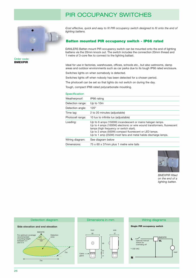
Batten mounted PIR occupancy switch - IP66 rated
order code: BMEXPIR
Specification
Weatherproof: IP66 rating
Detection range: Up to 10m
Detection angle: 120°
Time lag: 2 to 20 minutes (adjustable)
Photocell range: 10 lux to infinite lux (adjustable)
Loading: Up to 6 amps (1500W) incandescent or mains halogen lamps. Up to 4 amps (1000W) electronic or wire wound transformers, fl uorescent lamps (high frequency or switch start). Up to 2 amps (500W) compact fl uorescent or LED lamps. Up to 1 amp (250W) most fans and metal halide discharge lamps.
Wiring diagram: See diagram below
Dimensions: 75 x 60 x 37mm plus 1 metre wire tails
Cost effective, quick and easy to fit PIR occupancy switch designed to fit onto the end of lighting battens.
230 VAC
L
N
load
BMExPIR
optional manual switch for overriding off
10
65
37
24 24
60
front side
Cablegland
5
17
DANLERS Batten mount PIR occupancy switch can be mounted onto the end of lighting battens via the 20mm knock out. The switch includes the connection 20mm thread and 1 metre of 3-core fl ex to connect to the lighting ballast.
Ideal for use in factories, warehouses, offi ces, schools etc., but also wetrooms, damp areas and outdoor environments such as car parks due to its tough IP66 rated enclosure.
Switches lights on when somebody is detected.
Switches lights off when nobody has been detected for a chosen period.
The photocell can be set so that lights do not switch on during the day.
Tough, compact IP66 rated polycarbonate moulding.
7m
Detection zone
7m
50°
100°
BMEXPIR
Side elevation and end elevation
For optimum coveragerecommended mounting height between 2.4 and 5 m
Single PIR occupancy switch
SL
detection diagram
BMEXPIR fitted on the end of a lighting batten.
26
pir OCCupanCy SWitCHES
Cost effective, quick and easy to fit PIR occupancy switch designed to fit onto the end of lighting battens.
DANLERS Batten mount PIR occupancy switch can be mounted onto the end of lighting battens via the 20mm knock out. The switch includes the connection 20mm thread and 1 metre of 3-core fl ex to connect to the lighting ballast.
order code: CEFL PIR LR
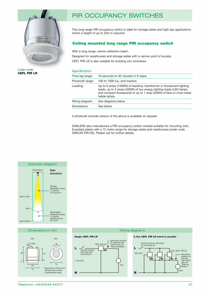
Ceiling mounted long range PIR occupancy switch
Single CEFL PIR LR A few CEFL PIR LR wired in parallel
L
load
optional manual wall switch for overriding off
A few CEFL PIR LR230 VAC alternative
position for optional wall switch (see p.8 “Start-up Mode”)
N
L
load
CEFL PIR LR
optional manual wall switch for overriding off
230 VAC
alternative position for optional wall switch (see p.8 “Start-up Mode”)
N
With a long range, narrow detection beam.
Designed for warehouses and storage aisles with a narrow point of access.
CEFL PIR LR is also suitable for building into luminaires.
Specification
Time lag range: 10 seconds to 40 minutes in 9 steps
Photocell range: 100 to 1000 lux, and inactive
Loading: Up to 6 amps (1500W) of resistive, transformer or fluorescent lighting loads, up to 2 amps (500W) of low energy lighting loads (LED lamps and compact fluorescent) or up to 1 amp (250W) of fans or most metal halide lamps
Wiring diagram: See diagrams below
Dimensions: See below
A photocell override version of the above is available on request.
DANLERS also manufacture a PIR occupancy switch module suitable for mounting onto Eurodata plates with a 12 metre range for storage aisles and warehouses (order code gREUW PIR12E). Please call for further details.
This long range PIR occupancy switch is ideal for storage aisles and high bay applications where a height of up to 20m is required.
55
3
2m cable
60
72
72
side plan
66
Requires 63 or 64mm (2.5") diameter hole in a false or plasterboard ceiling
38
17
CEFLPIRLR
Strong Detection Zonei.e. person moving arm
Secondary Detection Zonei.e. person walking across the zone
Up to 10m
Up to 20m
15m
6°
Side elevation
SL
SL SL SL
detection diagram
dimensions in mm Wiring diagrams
telephone: +44(0)1249 443377 27
pir OCCupanCy SWitCHES
order code:
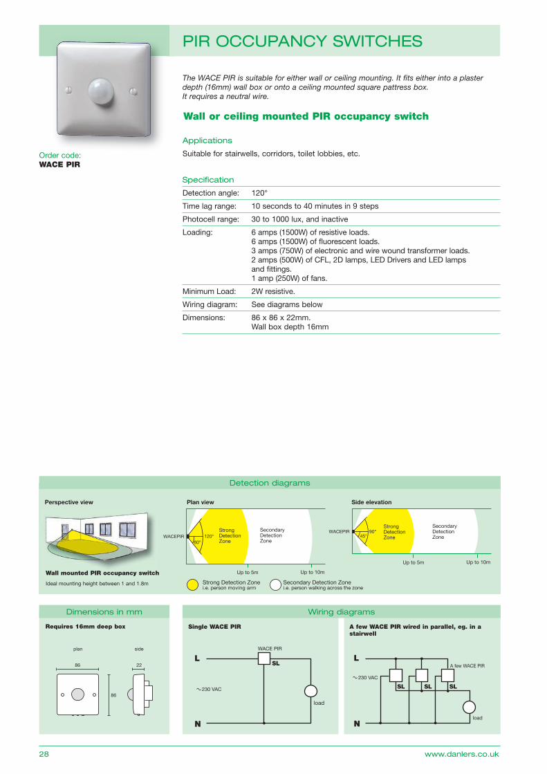
Wall or ceiling mounted PIR occupancy switch
The WACE PIR is suitable for either wall or ceiling mounting. It fits either into a plaster depth (16mm) wall box or onto a ceiling mounted square pattress box. It requires a neutral wire.
order code: WACE PIR
applications
Suitable for stairwells, corridors, toilet lobbies, etc.
Specification
Detection angle: 120°
Time lag range: 10 seconds to 40 minutes in 9 steps
Photocell range: 30 to 1000 lux, and inactive
Loading: 6 amps (1500W) of resistive loads. 6 amps (1500W) of fl uorescent loads. 3 amps (750W) of electronic and wire wound transformer loads. 2 amps (500W) of CFL, 2D lamps, LED Drivers and LED lamps and fi ttings. 1 amp (250W) of fans.
Minimum Load: 2W resistive.
Wiring diagram: See diagrams below
Dimensions: 86 x 86 x 22mm. Wall box depth 16mm
Single WACE PIR A few WACE PIR wired in parallel, eg. in a stairwell
Requires 16mm deep box
Up to 5m Up to 10m
WACEPIR Strong Detection Zone
Secondary Detection Zone 60°
120°
Up to 5m Up to 10m
StrongDetectionZone
SecondaryDetectionZone45°
90° WACEPIR
Up to 5m Up to 10m
WAPIR Strong Detection Zone
Secondary Detection Zone 60°
120°
Up to 5m Up to 10m
Strong Detection Zone
Secondary Detection Zone 45°
90° WAPIR
Strong Detection Zonei.e. person moving arm
Secondary Detection Zonei.e. person walking across the zone
Strong Detection Zonei.e. person moving arm
Secondary Detection Zonei.e. person walking across the zone
Plan view Side elevation
Wall mounted PIR occupancy switch
Ideal mounting height between 1 and 1.8m
L
Nload
A few WACE PIR
230 VAC
load
L
N
WACE PIR
230 VAC
plan side
2286
86
Perspective view
SL
SL SL SL
dimensions in mm Wiring diagrams
detection diagrams
28 www.danlers.co.uk
pir OCCupanCy SWitCHES
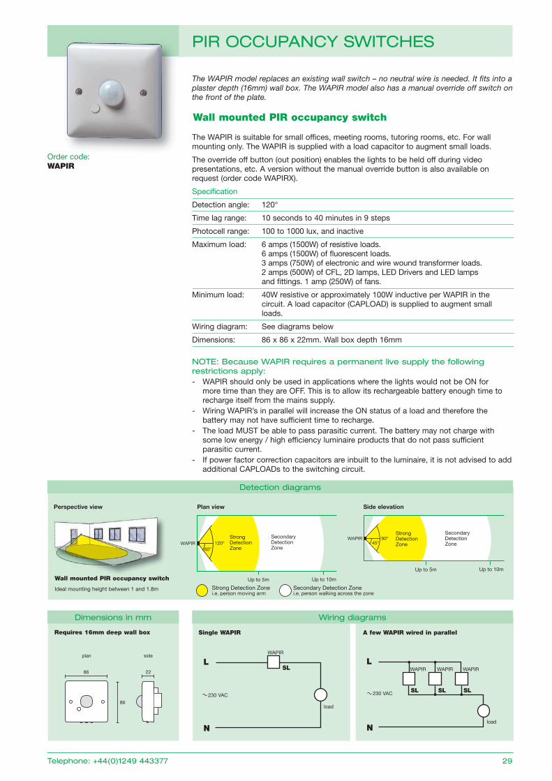
The WAPIR model replaces an existing wall switch – no neutral wire is needed. It fits into a plaster depth (16mm) wall box. The WAPIR model also has a manual override off switch on the front of the plate.
Wall mounted PIR occupancy switch
order code: WAPIR
The WAPIR is suitable for small offices, meeting rooms, tutoring rooms, etc. For wall mounting only. The WAPIR is supplied with a load capacitor to augment small loads.
The override off button (out position) enables the lights to be held off during video presentations, etc. A version without the manual override button is also available on request (order code WAPIRx).
Specification
Detection angle: 120°
Time lag range: 10 seconds to 40 minutes in 9 steps
Photocell range: 100 to 1000 lux, and inactive
Maximum load: 6 amps (1500W) of resistive loads. 6 amps (1500W) of fl uorescent loads. 3 amps (750W) of electronic and wire wound transformer loads. 2 amps (500W) of CFL, 2D lamps, LED Drivers and LED lamps and fi ttings. 1 amp (250W) of fans.
Minimum load: 40W resistive or approximately 100W inductive per WAPIR in the circuit. A load capacitor (CAPLoAD) is supplied to augment small loads.
Wiring diagram: See diagrams below
Dimensions: 86 x 86 x 22mm. Wall box depth 16mm
nOtE: because Wapir requires a permanent live supply the following restrictions apply: - WAPIR should only be used in applications where the lights would not be oN for
more time than they are oFF. This is to allow its rechargeable battery enough time to recharge itself from the mains supply.
- Wiring WAPIR’s in parallel will increase the oN status of a load and therefore the battery may not have sufficient time to recharge.
- The load MUST be able to pass parasitic current. The battery may not charge with some low energy / high efficiency luminaire products that do not pass sufficient parasitic current.
- If power factor correction capacitors are inbuilt to the luminaire, it is not advised to add additional CAPLoADs to the switching circuit.
Single WAPIR A few WAPIR wired in parallelRequires 16mm deep wall box
Up to 5m Up to 10m
WACEPIR Strong Detection Zone
Secondary Detection Zone 60°
120°
Up to 5m Up to 10m
StrongDetectionZone
SecondaryDetectionZone45°
90° WACEPIR
Up to 5m Up to 10m
WAPIR Strong Detection Zone
Secondary Detection Zone 60°
120°
Up to 5m Up to 10m
Strong Detection Zone
Secondary Detection Zone 45°
90° WAPIR
Strong Detection Zonei.e. person moving arm
Secondary Detection Zonei.e. person walking across the zone
Strong Detection Zonei.e. person moving arm
Secondary Detection Zonei.e. person walking across the zone
Plan view Side elevation
Wall mounted PIR occupancy switch
Ideal mounting height between 1 and 1.8m
L
Nload
WAPIR WAPIR WAPIR
230 VAC
L
N
230 VAC
load
WAPIRplan side
2286
86
Perspective view
SL
SL SLSL
dimensions in mm Wiring diagrams
detection diagrams
telephone: +44(0)1249 443377 29
pir OCCupanCy SWitCHES
order code:
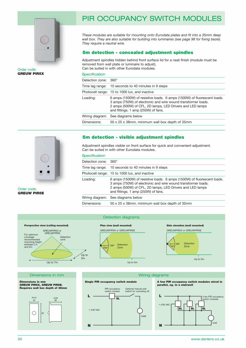
These modules are suitable for mounting onto Eurodata plates and fit into a 35mm deep wall box. They are also suitable for building into luminaires (see page 98 for fixing bezel). They require a neutral wire.
order code: GREUW PIR5X
5m detection - concealed adjustment spindles
Adjustment spindles hidden behind front surface lid for a neat finish (module must be removed from wall plate or luminaire to adjust).Can be suited in with other Eurodata modules.
Specification
Detection zone: 360°
Time lag range: 10 seconds to 40 minutes in 9 steps
Photocell range: 15 to 1000 lux, and inactive
Loading: 6 amps (1500W) of resistive loads. 6 amps (1500W) of fl uorescent loads. 3 amps (750W) of electronic and wire wound transformer loads. 2 amps (500W) of CFL, 2D lamps, LED Drivers and LED lamps and fi ttings. 1 amp (250W) of fans.
Wiring diagram: See diagrams below
Dimensions: 50 x 25 x 38mm, minimum wall box depth of 35mm
A few PIR occupancy switch modules wired in parallel, eg. in a stairwell
L
Nload
A few PIR occupancy switch modules
230 VAC
Dimensions in mmGREUW PIR5X, GREUW PIR5E.Requires wall box depth of 35mm
3825
50
front side
order code: GREUW PIR5E
5m detection - visible adjustment spindles
Adjustment spindles visible on front surface for quick and convenient adjustment. Can be suited in with other Eurodata modules.
Specification
Detection zone: 360°
Time lag range: 10 seconds to 40 minutes in 9 steps
Photocell range: 15 to 1000 lux, and inactive
Loading: 6 amps (1500W) of resistive loads. 6 amps (1500W) of fl uorescent loads. 3 amps (750W) of electronic and wire wound transformer loads. 2 amps (500W) of CFL, 2D lamps, LED Drivers and LED lamps and fi ttings. 1 amp (250W) of fans.
Wiring diagram: See diagrams below
Dimensions: 50 x 25 x 38mm, minimum wall box depth of 35mm
Up to 7m
GREUWPIR5X or GREUWPIR5E
Detection zone
For optimum coveragerecommended mounting height between 2.4 and 5m
Up to5m
Plan view (wall mounted)
GREUWPIR5X or GREUWPIR5E
Side elevation (wall mounted)
GREUWPIR5X or GREUWPIR5E
Perspective view (ceiling mounted)
Up to 5m
DetectionZone40°
80°
Up to 5m
DetectionZone50°
100°
SL SL SL
dimensions in mm
detection diagrams
30 www.danlers.co.uk
pir OCCupanCy SWitCH MOduLES
order code:
Single PIR occupancy switch module
load
L
N
PIR occupancy switch module
230 VAC
optional manual wall switch for overriding off
SL
Wiring diagrams
Single PIR occupancy switch module
load
L
N
PIR occupancy switch module
230 VAC
optional manual wall switch for overriding off
SL
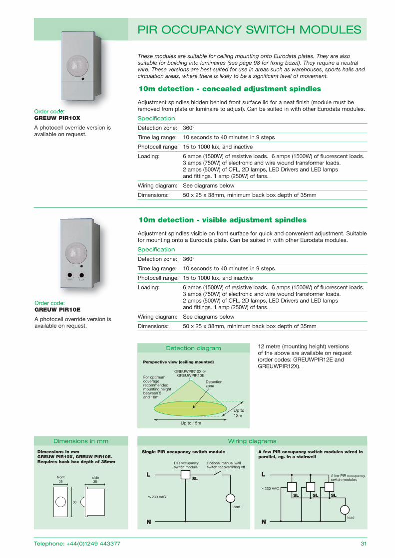
These modules are suitable for ceiling mounting onto Eurodata plates. They are also suitable for building into luminaires (see page 98 for fixing bezel). They require a neutral wire. These versions are best suited for use in areas such as warehouses, sports halls and circulation areas, where there is likely to be a significant level of movement.
order code: GREUW PIR10X
A photocell override version is available on request.
10m detection - concealed adjustment spindles
Adjustment spindles hidden behind front surface lid for a neat finish (module must be removed from plate or luminaire to adjust). Can be suited in with other Eurodata modules.
Specification
Detection zone: 360°
Time lag range: 10 seconds to 40 minutes in 9 steps
Photocell range: 15 to 1000 lux, and inactive
Loading: 6 amps (1500W) of resistive loads. 6 amps (1500W) of fl uorescent loads. 3 amps (750W) of electronic and wire wound transformer loads. 2 amps (500W) of CFL, 2D lamps, LED Drivers and LED lamps and fi ttings. 1 amp (250W) of fans.
Wiring diagram: See diagrams below
Dimensions: 50 x 25 x 38mm, minimum back box depth of 35mm
A few PIR occupancy switch modules wired in parallel, eg. in a stairwell
L
Nload
A few PIR occupancy switch modules
230 VAC
Dimensions in mmGREUW PIR10X, GREUW PIR10E.Requires back box depth of 35mm
3825
50
front side
order code: GREUW PIR10E
A photocell override version is available on request.
10m detection - visible adjustment spindles
Adjustment spindles visible on front surface for quick and convenient adjustment. Suitable for mounting onto a Eurodata plate. Can be suited in with other Eurodata modules.
Specification
Detection zone: 360°
Time lag range: 10 seconds to 40 minutes in 9 steps
Photocell range: 15 to 1000 lux, and inactive
Loading: 6 amps (1500W) of resistive loads. 6 amps (1500W) of fl uorescent loads. 3 amps (750W) of electronic and wire wound transformer loads. 2 amps (500W) of CFL, 2D lamps, LED Drivers and LED lamps and fi ttings. 1 amp (250W) of fans.
Wiring diagram: See diagrams below
Dimensions: 50 x 25 x 38mm, minimum back box depth of 35mm
Up to 15m
GREUWPIR10X or GREUWPIR10E
Detection zone
For optimum coveragerecommended mounting height between 5 and 10m
Up to12m
Perspective view (ceiling mounted)
SL SL SL
dimensions in mm Wiring diagrams
detection diagram 12 metre (mounting height) versions of the above are available on request (order codes: gREUWPIR12E and gREUWPIR12x).
telephone: +44(0)1249 443377 31
pir OCCupanCy SWitCH MOduLES
order code: