pins & bushings – metric
TRANSCRIPT
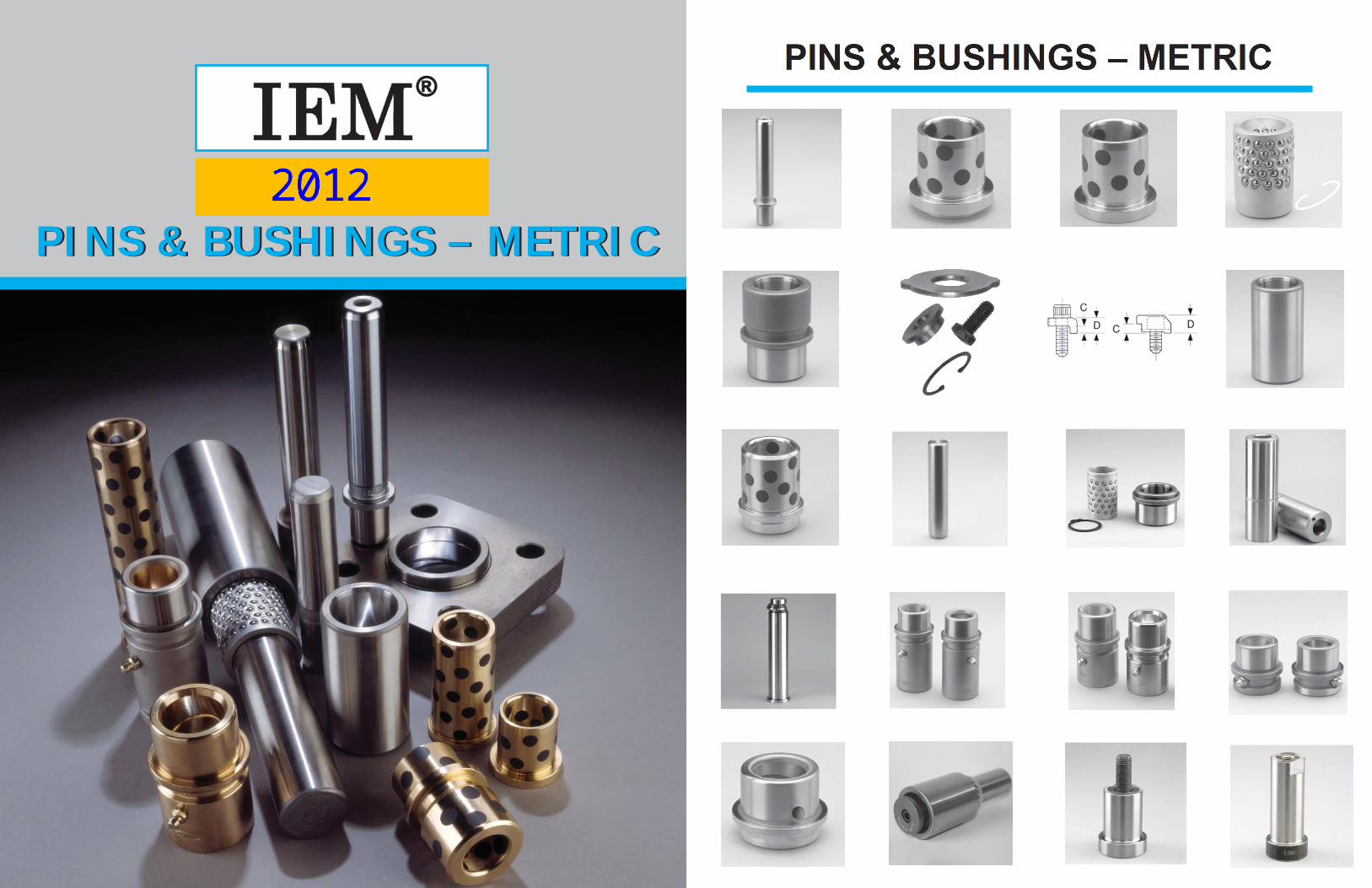
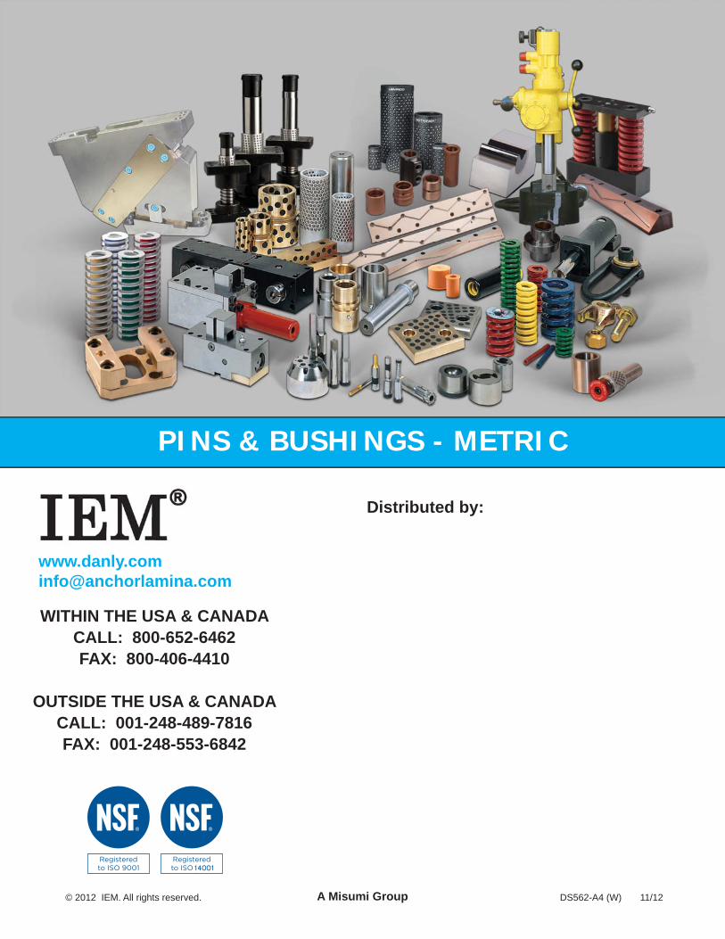
PINS & BUSHINGS – METRICPINS & BUSHINGS – METRIC
PINS & BUSHINGS – METRIC
CONTENTS
General Information 1
Plain & Ball Bearing Guide Posts Press Fit Guide Posts 2Demountable Guide Posts 4Automotive Straight Guide Posts 6
Plain Bearing & Self-Lubricating Bushings Automotive Demountable Self-Lubricating Guide Post Bushings 8Automotive Demountable Self-Lubricating PAD Bushings 9Automotive Demountable Self-Lubricating Bushings Clamps 10Lifter Pins 13Demountable Plain Bearing Bushings (Extra Long, Standard and Short Shoulder Series) 14Demountable Plain Bearing Low Profi le Bushings 16Self-Lubricating Ejector Bushings 17
Ball Bearing Components Ball Bearing Cages 18Ball Bearing Demountable Bushings 19Ball Bearing Straight Sleeve Bushings 20Demountable Ball Bearing Stripper Bushings & Cages 21
Technical InformationMounting Accessories 22Ball Bearing Selection Guide 23Bore Size Data 30Clamping Specifi cations for Demountable Post & Bushings 32
MiscellaneousCage Stopper End Caps 34Pad Retainers – Standard Mount – Metric 35Pad Retainers – Reverse Mount – Metric 36
PAGE NUMBER
1
General Information
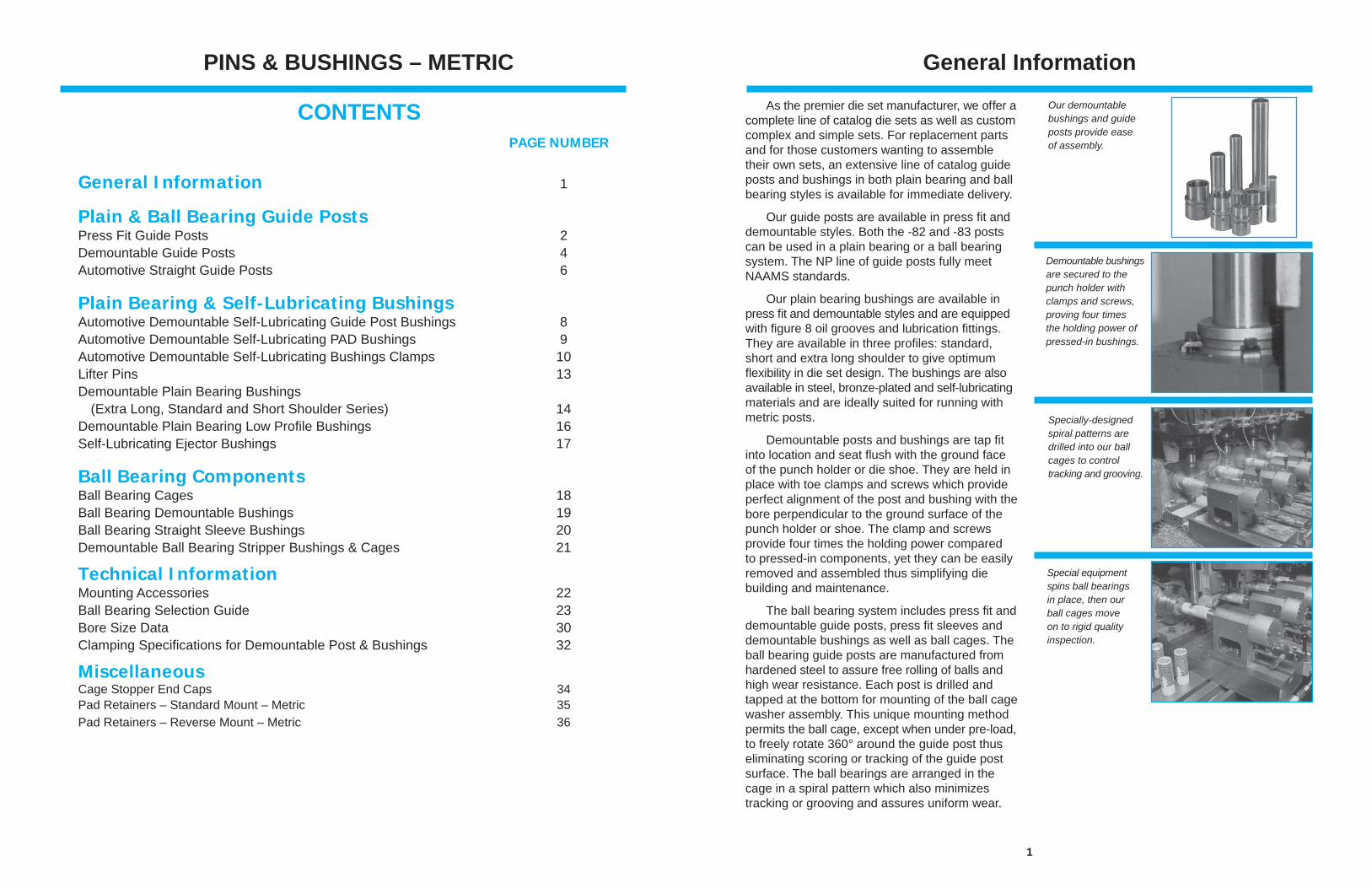
As the premier die set manufacturer, we offer aco mplete line of catalog die sets as well as custom complex and simple sets. For replacement parts and for those customers wanting to assemble their own sets, an extensive line of catalog guide posts and bushings in both plain bearing and ball bearing styles is available for immediate delivery.
Our guide posts are available in press fi t and demountable styles. Both the -82 and -83 posts can be used in a plain bearing or a ball bearing system. The NP line of guide posts fully meet NAAMS standards.
Our plain bearing bushings are available in press fi t and demountable styles and are equipped with fi gure 8 oil grooves and lubrication fi ttings. They are available in three profi les: standard, short and extra long shoulder to give optimum fl exibility in die set design. The bushings are also available in steel, bronze-plated and self-lubricating materials and are ideally suited for running with metric posts.
Demountable posts and bushings are tap fi t into location and seat fl ush with the ground face of the punch holder or die shoe. They are held in place with toe clamps and screws which provide perfect alignment of the post and bushing with thebore perpendicular to the ground surface of the punch holder or shoe. The clamp and screwsprovide four times the holding power comparedto pressed-in components, yet they can be easilyremoved and assembled thus simplifying die building and maintenance.
The ball bearing system includes press fi t and demountable guide posts, press fi t sleeves and demountable bushings as well as ball cages. The ball bearing guide posts are manufactured from hardened steel to assure free rolling of balls and high wear resistance. Each post is drilled and tapped at the bottom for mounting of the ball cage washer assembly. This unique mounting method permits the ball cage, except when under pre-load,to freely rotate 360° around the guide post thus eliminating scoring or tracking of the guide post surface. The ball bearings are arranged in the cage in a spiral pattern which also minimizes tracking or grooving and assures uniform wear.
Our demountable bushings and guide posts provide ease of assembly.
Demountable bushingsare secured to the punch holder with clamps and screws, proving four times the holding power of pressed-in bushings.
Special equipment spins ball bearings in place, then ourball cages moveon to rigid qualityinspection.
Specially-designed spiral patterns are drilled into our ball cages to control tracking and grooving.
2
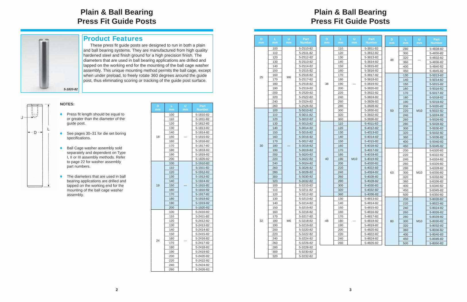
Plain & Ball Bearing Press Fit Guide Posts
These press fi t guide posts are designed to run in both a plain and ball bearing systems. They are manufactured from high quality hardened steel and fi nish ground for a high precision fi nish. The diameters that are used in ball bearing applications are drilled and tapped on the working end for the mounting of the ball cage washer assembly. This unique mounting method permits the ball cage, except when under preload, to freely rotate 360 degrees around the guide post, thus eliminating scoring or tracking of the guide post surface.
Product Features
5-1820-82
NOTES:
Press fi t length should be equal to or greater than the diameter of the guide post.
See pages 30–31 for die set boring specifi cations.
Ball Cage washer assembly sold separately and dependent on Type I, II or III assembly methods. Refer to page 22 for washer assembly part numbers.
The diameters that are used in ball bearing applications are drilled and tapped on the working end for the mounting of the ball cage washer assembly.
Dmm
Lmm
Umm
PartNumber
18
100
—
5-1810-82110 5-1811-82120 5-1812-82130 5-1813-82140 5-1814-82150 5-1815-82160 5-1816-82170 5-1817-82180 5-1818-82190 5-1819-82200 5-1820-82
19
100
—
5-1910-82110 5-1911-82120 5-1912-82130 5-1913-82140 5-1914-82150 5-1915-82160 5-1916-82170 5-1917-82180 5-1918-82190 5-1919-82200 5-1920-82
24
100
—
5-2410-82110 5-2411-82120 5-2412-82130 5-2413-82140 5-2414-82150 5-2415-82160 5-2416-82170 5-2417-82180 5-2418-82190 5-2419-82200 5-2420-82220 5-2422-82240 5-2424-82260 5-2426-82
3
Plain & Ball Bearing Press Fit Guide Posts
Dmm
Lmm
Umm
PartNumber
25
100
M6
5-2510-82110 5-2511-82120 5-2512-82130 5-2513-82140 5-2514-82150 5-2515-82160 5-2516-82170 5-2517-82180 5-2518-82190 5-2519-82200 5-2520-82220 5-2522-82240 5-2524-82260 5-2526-82
30
100
—
5-3010-82110 5-3011-82120 5-3012-82130 5-3013-82140 5-3014-82150 5-3015-82160 5-3016-82170 5-3017-82180 5-3018-82190 5-3019-82200 5-3020-82220 5-3022-82240 5-3024-82260 5-3026-82280 5-3028-82300 5-3030-82320 5-3032-82
32
100
M6
5-3210-82110 5-3211-82120 5-3212-82130 5-3213-82140 5-3214-82150 5-3215-82160 5-3216-82170 5-3217-82180 5-3218-82190 5-3219-82200 5-3220-82220 5-3222-82240 5-3224-82260 5-3226-82280 5-3228-82300 5-3230-82320 5-3232-82
Dmm
Lmm
Umm
PartNumber
38
110
—
5-3811-82120 5-3812-82130 5-3813-82140 5-3814-82150 5-3815-82160 5-3816-82170 5-3817-82180 5-3818-82190 5-3819-82200 5-3820-82220 5-3822-82240 5-3824-82260 5-3826-82280 5-3828-82300 5-3830-82320 5-3832-82360 5-3836-82
40
110
M10
5-4011-82120 5-4012-82130 5-4013-82140 5-4014-82150 5-4015-82160 5-4016-82170 5-4017-82180 5-4018-82190 5-4019-82200 5-4020-82220 5-4022-82240 5-4024-82260 5-4026-82280 5-4028-82300 5-4030-82320 5-4032-82360 5-4036-82
48
130
—
5-4813-82140 5-4814-82150 5-4815-82160 5-4816-82170 5-4817-82180 5-4818-82190 5-4819-82200 5-4820-82220 5-4822-82240 5-4824-82260 5-4826-82
Dmm
Lmm
Umm
PartNumber
48
280
—
5-4828-82300 5-4830-82320 5-4832-82360 5-4836-82400 5-4840-82450 5-4845-82
50
130
M10
5-5013-82140 5-5014-82150 5-5015-82160 5-5016-82170 5-5017-82180 5-5018-82190 5-5019-82200 5-5020-82220 5-5022-82240 5-5024-82260 5-5026-82280 5-5028-82300 5-5030-82320 5-5032-82360 5-5036-82400 5-5040-82450 5-5045-82
63
200
M10
5-6320-82220 5-6322-82240 5-6324-82260 5-6326-82280 5-6328-82300 5-6330-82320 5-6332-82360 5-6336-82400 5-6340-82450 5-6345-82500 5-6350-82
80
200
M10
5-8020-82220 5-8022-82240 5-8024-82260 5-8026-82280 5-8028-82300 5-8030-82320 5-8032-82360 5-8036-82400 5-8040-82450 5-8045-82500 5-8050-82
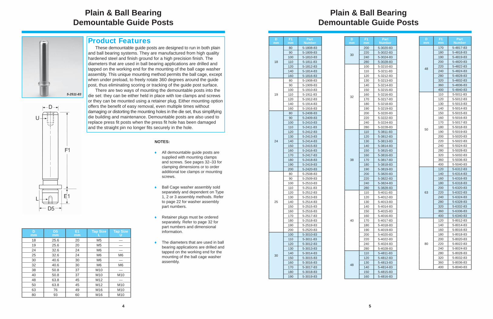
4
Dmm
D5mm
E1mm
Tap SizeL
Tap SizeU
18 25.6 20 M5 —19 25.6 20 M5 —24 32.6 24 M6 —25 32.6 24 M6 M630 40.6 30 M6 —32 40.6 30 M6 M638 50.8 37 M10 —40 50.8 37 M10 M1048 63.8 45 M12 —50 63.8 45 M12 M1063 76 49 M16 M1080 93 60 M16 M10
These demountable guide posts are designed to run in both plain and ball bearing systems. They are manufactured from high quality hardened steel and fi nish ground for a high precision fi nish. The diameters that are used in ball bearing applications are drilled and tapped on the working end for the mounting of the ball cage washer assembly. This unique mounting method permits the ball cage, except when under preload, to freely rotate 360 degrees around the guide post, thus eliminating scoring or tracking of the guide post surface. There are two ways of mounting the demountable posts into the die set: they can be either held in place with toe clamps and screws or they can be mounted using a retainer plug. Either mounting option offers the benefi t of easy removal, even multiple times without damaging or distorting the mounting holes in the die set, thus simplifying die building and maintenance. Demountable posts are also used to replace press fi t posts when the press fi t hole has been damaged and the straight pin no longer fi ts securely in the hole.
Plain & Ball Bearing Demountable Guide Posts
5-2511-83
Product Features
NOTES:
All demountable guide posts are supplied with mounting clamps and screws. See pages 32–33 for clamping dimensions or to order additional toe clamps or mounting screws.
Ball Cage washer assembly sold separately and dependent on Type 1, 2 or 3 assembly methods. Refer to page 22 for washer assembly part numbers.
Retainer plugs must be ordered separately. Refer to page 32 for part numbers and dimensional information.
The diameters that are used in ball bearing applications are drilled and tapped on the working end for the mounting of the ball cage washer assembly.
5
Plain & Ball Bearing Demountable Guide Posts
Dmm
F1mm
PartNumber
18
80 5-1808-8390 5-1809-83100 5-1810-83110 5-1811-83120 5-1812-83140 5-1814-83160 5-1816-83
19
80 5-1908-8390 5-1909-83100 5-1910-83110 5-1911-83120 5-1912-83140 5-1914-83160 5-1916-83
24
80 5-2408-8390 5-2409-83100 5-2410-83110 5-2411-83120 5-2412-83130 5-2413-83140 5-2414-83150 5-2415-83160 5-2416-83170 5-2417-83180 5-2418-83190 5-2419-83200 5-2420-83
25
80 5-2508-8390 5-2509-83100 5-2510-83110 5-2511-83120 5-2512-83130 5-2513-83140 5-2514-83150 5-2515-83160 5-2516-83170 5-2517-83180 5-2518-83190 5-2519-83200 5-2520-83
30
100 5-3010-83110 5-3011-83120 5-3012-83130 5-3013-83140 5-3014-83150 5-3015-83160 5-3016-83170 5-3017-83180 5-3018-83190 5-3019-83
Dmm
F1mm
PartNumber
30
200 5-3020-83220 5-3022-83240 5-3024-83280 5-3028-83
32
100 5-3210-83110 5-3211-83120 5-3212-83130 5-3213-83140 5-3214-83150 5-3215-83160 5-3216-83170 5-3217-83180 5-3218-83190 5-3219-83200 5-3220-83220 5-3222-83240 5-3224-83280 5-3228-83
38
110 5-3811-83120 5-3812-83130 5-3813-83140 5-3814-83150 5-3815-83160 5-3816-83170 5-3817-83180 5-3818-83190 5-3819-83200 5-3820-83220 5-3822-83240 5-3824-83280 5-3828-83
40
110 5-4011-83120 5-4012-83130 5-4013-83140 5-4014-83150 5-4015-83160 5-4016-83170 5-4017-83180 5-4018-83190 5-4019-83200 5-4020-83220 5-4022-83240 5-4024-83280 5-4028-83
48
110 5-4811-83120 5-4812-83130 5-4813-83140 5-4814-83150 5-4815-83160 5-4816-83
Dmm
F1mm
PartNumber
48
170 5-4817-83180 5-4818-83190 5-4819-83200 5-4820-83220 5-4822-83240 5-4824-83280 5-4828-83320 5-4832-83360 5-4836-83400 5-4840-83
50
110 5-5011-83120 5-5012-83130 5-5013-83140 5-5014-83150 5-5015-83160 5-5016-83170 5-5017-83180 5-5018-83190 5-5019-83200 5-5020-83220 5-5022-83240 5-5024-83280 5-5028-83320 5-5032-83360 5-5036-83400 5-5040-83
63
120 5-6312-83140 5-6314-83160 5-6316-83180 5-6318-83200 5-6320-83220 5-6322-83240 5-6324-83280 5-6328-83320 5-6332-83360 5-6336-83400 5-6340-83
80
120 5-8012-83140 5-8014-83160 5-8016-83180 5-8018-83200 5-8020-83220 5-8022-83240 5-8024-83280 5-8028-83320 5-8032-83360 5-8036-83400 5-8040-83
6
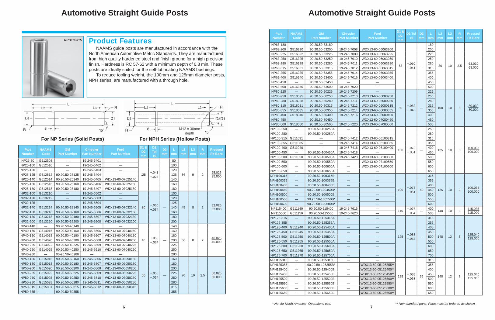
Automotive Straight Guide Posts
NAAMS guide posts are manufactured in accordance with the North American Automotive Metric Standards. They are manufactured from high quality hardened steel and fi nish ground for a high precision fi nish. Hardness is RC 57-62 with a minimum depth of 0.8 min. These posts are ideally suited for the self-lubricating NAAMS bushings. To reduce tooling weight, the 100mm and 125mm diameter posts, NPH series, are manufactured with a through hole.
Product Features
For NP Series (Solid Posts) For NPH Series (Hollow Posts)
NPH100315
PartNumber
NAAMS Code
GMPart Number
ChryslerPart Number
FordPart Number
D1 & D2mm
D2Tol r6
D3mm
Lmm
L2mm
L3mm
Rmm
PressedFit Bore
NP25-80 G512508 — 19-245-6401 —
.25 +.041+.028 —
80
36 9 2 25.02525.000
NP25-100 G512510 — 19-245-6402 — 100NP25-120 — — 19-245-6403 — 120NP25-125 G512512 90.20.50-25125 19-245-6404 — 125NP25-140 G512514 90.20.50-25140 19-245-6405 WDX13-60-07025140 140NP25-160 G512516 90.20.50-25160 19-245-6406 WDX13-60-07025160 160NP25-180 G512518 90.20.50-25180 19-245-6407 WDX13-60-07025180 180NP32-100 G513210 — 19-245-6502 —
30 +.050+.034 —
100
45 8 2 32.02532.000
NP32-120 G513212 — 19-245-6503 — 120NP32-125 — — 19-245-6504 — 125NP32-140 G513214 90.20.50-32140 19-245-6505 WDX13-60-07032140 140NP32-160 G513216 90.20.50-32160 19-245-6506 WDX13-60-07032160 160NP32-180 G513218 90.20.50-32180 19-245-6507 WDX13-60-07032180 180NP32-200 G513220 90.20.50-32200 19-245-6508 WDX13-60-07032200 200NP40-140 — 90.20.50-40140 — —
40 +.050+.034 —
140
56 8 2 40.02540.000
NP40-160 G514016 90.20.50-40160 19-245-6606 WDX13-60-07040160 160NP40-180 G514018 90.20.50-40180 19-245-6607 WDX13-60-07040180 180NP40-200 G514020 90.20.50-40200 19-245-6608 WDX13-60-07040200 200NP40-225 G514022 90.20.50-40225 19-245-6609 WDX13-60-07040225 225NP40-250 G514025 90.20.50-40250 19-245-6610 WDX13-60-07040250 250NP40-280 — 90-20.50-40280 — — 280NP50-160 G515016 90.20.50-50160 19-245-6806 WDX13-60-06050160
50 +.050+.034 —
160
70 10 2.5 50.02550.000
NP50-180 G515018 90.20.50-50180 19-245-6807 WDX13-60-06050180 180NP50-200 G515020 90.20.50-50200 19-245-6808 WDX13-60-06050200 200NP50-225 G515022 90.20.50-50225 19-245-6809 WDX13-60-06050225 225NP50-250 G515025 90.20.50-50250 19-245-6810 WDX13-60-06050250 250NP50-280 G515028 90.20.50-50280 19-245-6811 WDX13-60-06050280 280NP50-315 G515031 90.20.50-50315 19-245-6812 WDX13-60-06050315 315NP50-355 — 90.20.50-50355 — — 355
7
Automotive Straight Guide Posts
* Not for North American Operations use. ** Non-standard parts. Parts must be ordered as shown.
PartNumber
NAAMS Code
GMPart Number
ChryslerPart Number
FordPart Number
D1 & D2mm
D2 Tol r6
D3mm
Lmm
L2mm
L3mm
Rmm
PressedFit Bore
NP63-180 — 90.20.50-63180 — —
63 +.060+.041 —
180
80 10 2.5 63.03063.000
NP63-200 G516320 90.20.50-63200 19-245-7008 WDX13-60-06063200 200NP63-225 G516322 90.20.50-63225 19-245-7009 WDX13-60-06063225 225NP63-250 G516325 90.20.50-63250 19-245-7010 WDX13-60-06063250 250NP63-280 G516328 90.20.50-63280 19-245-7011 WDX13-60-06063280 280NP63-315 G516331 90.20.50-63315 19-245-7012 WDX13-60-06063315 315NP63-355 G516335 90.20.50-63355 19-245-7014 WDX13-60-06063355 355NP63-400 G516340 90.20.50-63400 19-245-7016 WDX13-60-06063400 400NP63-450 — 90.20.50-63450 — — 450NP63-500 G516350 90.20.50-63500 19-245-7020 — 500NP80-225 — 90.20.50-80225 19-245-7209 —
80 +.062+.043 —
225
100 10 3 80.03080.000
NP80-250 G518025 90.20.50-80250 19-245-7210 WDX13-60-06080250 250NP80-280 G518028 90.20.50-80280 19-245-7211 WDX13-60-06080280 280NP80-315 G518031 90.20.50-80315 19-245-7212 WDX13-60-06080315 315NP80-355 G518035 90.20.50-80355 19-245-7214 WDX13-60-06080355 355NP80-400 G518040 90.20.50-80400 19-245-7216 WDX13-60-06080400 400NP80-450 — 90.20.50-80450 — WDX13-60-07080450 450NP80-500 G518050 90.20.50-80500 19-245-7220 WDX13-60-07080500 500NP100-250 — 90.20.50-100250A — —
100 +.073+.051 —
250
125 10 3 100.035100.000
NP100-280 — 90.20.50-100280A — — 280NP100-315 G511031 — 19-245-7412 WDX13-60-06100315 315NP100-355 G511035 — 19-245-7414 WDX13-60-06100355 355NP100-400 G511040 — 19-245-7416 WDX13-60-06100400 400NP100-450 — 90.20.50-100450A 19-245-7418 — 450NP100-500 G511050 90.20.50-100500A 19-245-7420 WDX13-60-07100500 500NP100-550 — 90.20.50-100550A — WDX13-60-07100550 550NP100-600 — 90.20.50-100600A — WDX13-60-07100600 600NP100-650 — 90.20.50-100650A — — 650NPH100315 — 90.20.50-100315B — —
100 +.073+.051 50
315
125 10 3 100.035100.000
NPH100355 — 90.20.50-100355B — — 355NPH100400 — 90.20.50-100400B — — 400NPH100450 — 90.20.50-100450B* — — 450NPH100500 — 90.20.50-100500B — — 500NPH100550 — 90.20.50-100550B* — — 550NPH100600 — 90.20.50-100600B* — — 600NP115400 G511140 90.20.50-115400 19-245-7616 —
115 +.076+.054 —
400140 10 3 115.035
115.000NP115500 G511150 90.20.50-115500 19-245-7620 — 500NP125-315 — 90.20.50-125315A — —
125 +.088+.063 —
315
140 12 3 125.040125.000
NP125-355 — 90.20.50-125355A — — 355NP125-400 G511240 90.20.50-125400A — — 400NP125-450 G511245 90.20.50-125450A — — 450NP125-500 G511250 90.20.50-125500A — — 500NP125-550 G511255 90.20.50-125550A — — 550NP125-600 G511260 90.20.50-125600A — — 600NP125-650 G511265 90.20.50-125650A — — 650NP125-700 G511270 90.20.50-125700A — — 700NPH125315 — 90.20.50-125315B — —
125 +.088+.063 65
315
140 12 3 125.040125.000
NPH125355 — 90.20.50-125355B* — WDX13-60-05125355** 355NPH125400 — 90.20.50-125400B — WDX13-60-05125400** 400NPH125450 — 90.20.50-125450B — WDX13-60-05125450** 450NPH125500 — 90.20.50-125500B — WDX13-60-05125500** 500NPH125550 — 90.20.50-125550B — WDX13-60-05125550** 550NPH125600 — 90.20.50-125600B — WDX13-60-05125600** 600NPH125650 — 90.20.50-125650B — WDX13-60-05125650** 650
8
CLAMP NOTES:
See pages 10–12 for clamp part numbers and dimensional information. OUR bushings will be supplied with (3) M8 toe clamps and screws
(#6-99-1). NAAMS bushings will be supplied with (3) M8 toe clamps and screws
(#6-99-1). GM bushings are supplied with NO clamps and screws. Order separately:
for 25-50mm, order (1) 90.20.60A clamp per bushing; for 63-125mm, order (2) 90.20.60B clamps per bushing.
CHRYSLER guide post bushings are supplied with NO clamps or screws. Order STOP/BUSHING CLAMP COMBINATION BLOCK separately. See Table 1 for sizes and part numbers.
Ford bushings: 32-50mm are supplied with (1) toe clamp (#MMC0219); 63mm-100mm are supplied with (2) toe clamps (#MMC0219).
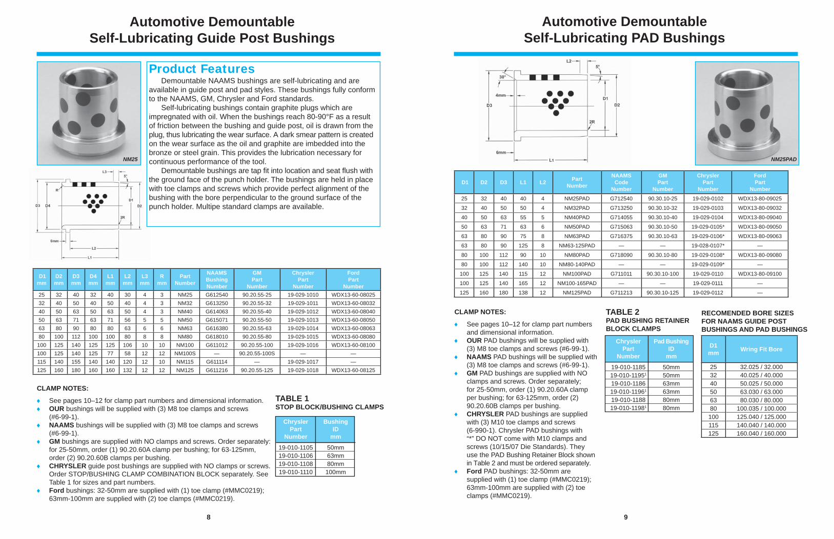
Automotive Demountable Self-Lubricating Guide Post Bushings
Demountable NAAMS bushings are self-lubricating and are available in guide post and pad styles. These bushings fully conform to the NAAMS, GM, Chrysler and Ford standards. Self-lubricating bushings contain graphite plugs which are impregnated with oil. When the bushings reach 80-90°F as a result of friction between the bushing and guide post, oil is drawn from the plug, thus lubricating the wear surface. A dark smear pattern is created on the wear surface as the oil and graphite are imbedded into the bronze or steel grain. This provides the lubrication necessary for continuous performance of the tool. Demountable bushings are tap fi t into location and seat fl ush with the ground face of the punch holder. The bushings are held in place with toe clamps and screws which provide perfect alignment of the bushing with the bore perpendicular to the ground surface of the punch holder. Multipe standard clamps are available.
Product Features
NM25
TABLE 1STOP BLOCK/BUSHING CLAMPS
Chrysler Bushing Part ID Number mm
19-010-1105 50mm 19-010-1106 63mm 19-010-1108 80mm 19-010-1110 100mm
D1mm
D2mm
D3mm
D4mm
L1mm
L2mm
L3mm
Rmm
PartNumber
NAAMSBushingNumber
GM Part
Number
ChryslerPart
Number
FordPart
Number25 32 40 32 40 30 4 3 NM25 G612540 90.20.55-25 19-029-1010 WDX13-60-0802532 40 50 40 50 40 4 3 NM32 G613250 90.20.55-32 19-029-1011 WDX13-60-0803240 50 63 50 63 50 4 3 NM40 G614063 90.20.55-40 19-029-1012 WDX13-60-0804050 63 71 63 71 56 5 5 NM50 G615071 90.20.55-50 19-029-1013 WDX13-60-0805063 80 90 80 80 63 6 6 NM63 G616380 90.20.55-63 19-029-1014 WDX13-60-0806380 100 112 100 100 80 8 8 NM80 G618010 90.20.55-80 19-029-1015 WDX13-60-08080100 125 140 125 125 106 10 10 NM100 G611012 90.20.55-100 19-029-1016 WDX13-60-08100100 125 140 125 77 58 12 12 NM100S — 90.20.55-100S — —115 140 155 140 140 120 12 10 NM115 G611114 — 19-029-1017 —125 160 180 160 160 132 12 12 NM125 G611216 90.20.55-125 19-029-1018 WDX13-60-08125
9
Automotive Demountable Self-Lubricating PAD Bushings
NM25PAD
CLAMP NOTES:
See pages 10–12 for clamp part numbers and dimensional information.
OUR PAD bushings will be supplied with (3) M8 toe clamps and screws (#6-99-1).
NAAMS PAD bushings will be supplied with(3) M8 toe clamps and screws (#6-99-1).
GM PAD bushings are supplied with NO clamps and screws. Order separately; for 25-50mm, order (1) 90.20.60A clamp per bushing; for 63-125mm, order (2) 90.20.60B clamps per bushing.
CHRYSLER PAD bushings are supplied with (3) M10 toe clamps and screws (6-990-1). Chrysler PAD bushings with “*” DO NOT come with M10 clamps and screws (10/15/07 Die Standards). They use the PAD Bushing Retainer Block shown in Table 2 and must be ordered separately.
Ford PAD bushings: 32-50mm are supplied with (1) toe clamp (#MMC0219); 63mm-100mm are supplied with (2) toe clamps (#MMC0219).
TABLE 2PAD BUSHING RETAINER BLOCK CLAMPS
Chrysler Pad Bushing Part ID Number mm
19-010-1185 50mm 19-010-11951 50mm 19-010-1186 63mm 19-010-11961 63mm 19-010-1188 80mm 19-010-11981 80mm
D1 D2 D3 L1 L2 PartNumber
NAAMSCode
Number
GM Part
Number
ChryslerPart
Number
FordPart
Number25 32 40 40 4 NM25PAD G712540 90.30.10-25 19-029-0102 WDX13-80-09025
32 40 50 50 4 NM32PAD G713250 90.30.10-32 19-029-0103 WDX13-80-09032
40 50 63 55 5 NM40PAD G714055 90.30.10-40 19-029-0104 WDX13-80-09040
50 63 71 63 6 NM50PAD G715063 90.30.10-50 19-029-0105* WDX13-80-09050
63 80 90 75 8 NM63PAD G716375 90.30.10-63 19-029-0106* WDX13-80-09063
63 80 90 125 8 NM63-125PAD — — 19-028-0107* —
80 100 112 90 10 NM80PAD G718090 90.30.10-80 19-029-0108* WDX13-80-09080
80 100 112 140 10 NM80-140PAD — — 19-029-0109* —
100 125 140 115 12 NM100PAD G711011 90.30.10-100 19-029-0110 WDX13-80-09100
100 125 140 165 12 NM100-165PAD — — 19-029-0111 —
125 160 180 138 12 NM125PAD G711213 90.30.10-125 19-029-0112 —
D1mm Wring Fit Bore
25 32.025 / 32.00032 40.025 / 40.00040 50.025 / 50.00050 63.030 / 63.00063 80.030 / 80.00080 100.035 / 100.000100 125.040 / 125.000115 140.040 / 140.000125 160.040 / 160.000
RECOMENDED BORE SIZES FOR NAAMS GUIDE POST BUSHINGS AND PAD BUSHINGS
10
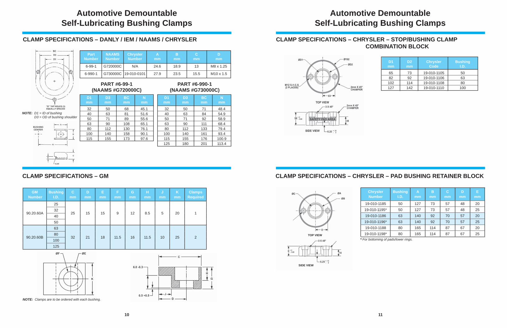
CLAMP SPECIFICATIONS – DANLY / IEM / NAAMS / CHRYSLER
NOTE: D1 = ID of bushing D3 = OD of bushing shoulder
Automotive Demountable Self-Lubricating Bushing Clamps
PART #6-99-1(NAAMS #G720000C)
PART #6-990-1(NAAMS #G730000C)
Part NAAMS Chrysler A B C D Number Number Number mm mm mm mm
6-99-1 G720000C N/A 24.6 18.9 13 M8 x 1.25
6-990-1 G730000C 19-010-0101 27.9 23.5 15.5 M10 x 1.5
CLAMP SPECIFICATIONS – GM
NOTE: Clamps are to be ordered with each bushing.
D1 D3 BC N mm mm mm mm
32 50 68 45.1 40 63 81 51.6 50 71 89 55.6 63 90 108 65.1 80 112 130 76.1 100 140 158 90.1 115 155 173 97.6
D1 D3 BC N mm mm mm mm
32 50 71 48.4 40 63 84 54.9 50 71 92 58.9 63 90 111 68.4 80 112 133 79.4 100 140 161 93.4 115 155 176 100.9 125 180 201 113.4
GM Number
BushingI.D.
C mm
D mm
Emm
Fmm
G mm
Hmm
Jmm
Kmm
ClampsRequired
90.20.60A
25
25 15 15 9 12 8.5 5 20 1324050
90.20.60B
63
32 21 18 11.5 16 11.5 10 25 280100125
11
Automotive Demountable Self-Lubricating Bushing Clamps
CLAMP SPECIFICATIONS – CHRYSLER – STOP/BUSHING CLAMP COMBINATION BLOCK
CLAMP SPECIFICATIONS – CHRYSLER – PAD BUSHING RETAINER BLOCK
* For bottoming of pads/lower rings.
D1 D2 Chrysler Bushing mm mm Code I.D.
65 73 19-010-1105 50 82 92 19-010-1106 63 102 114 19-010-1108 80 127 142 19-010-1110 100
ChryslerNumber
BushingI.D.
Amm
Bmm
C mm
D mm
Emm
19-010-1185 50 127 73 57 48 2019-010-1195* 50 127 73 57 48 2519-010-1186 63 140 92 70 57 2019-010-1196* 63 140 92 70 57 2519-010-1188 80 165 114 87 67 2019-010-1198* 80 165 114 87 67 25TOP VIEW
SIDE VIEW
12
Automotive Demountable Self-Lubricating Bushing Clamps
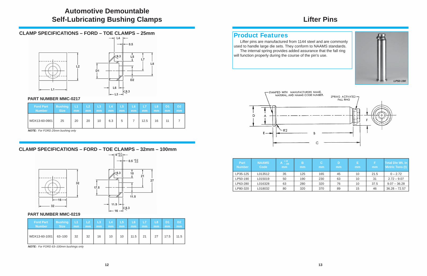
CLAMP SPECIFICATIONS – FORD – TOE CLAMPS – 25mm
CLAMP SPECIFICATIONS – FORD – TOE CLAMPS – 32mm – 100mm
NOTE: For FORD 25mm bushing only
NOTE: For FORD 63–100mm bushings only
PART NUMBER MMC-0219
PART NUMBER MMC-0217
Ford Part Bushing L1 L2 L3 L4 L5 L6 L7 L8 D1 D2 Number Size mm mm mm mm mm mm mm mm mm mm WDX13-60-0901 25 20 20 10 6.3 5 7 12.5 16 11 7
Ford Part Bushing L1 L2 L3 L4 L5 L6 L7 L8 D1 D2 Number Size mm mm mm mm mm mm mm mm mm mm WDX13-60-1001 63–100 32 32 16 10 10 11.5 21 27 17.5 11.5
13
Lifter Pins
Lifter pins are manufactured from 1144 steel and are commonly used to handle large die sets. They conform to NAAMS standards. The internal spring provides added assurance that the fall ring will function properly during the course of the pin’s use.
Product Features
LP50-190
Part NAAMS A B C D E F Total Die Wt. in Number Code mm mm mm mm mm mm Metric Tons (t)
LP35-125 L013512 35 125 165 45 10 21.5 0 – 2.72 LP50-190 L015019 50 190 230 63 10 31 2.72 – 9.07 LP63-280 L016328 63 280 320 76 10 37.5 9.07 – 36.28 LP80-320 L018032 80 320 370 89 15 46 36.28 – 72.57
+ 0- .03
14
NOTES:
All demountable bushings are supplied with mounting clamps and screws. See page 32–33 for clamping dimensions or to order additional toe clamps or mounting screws.
Bronze-plated bushings should not be pressed-in or honed.
See pages 30–31 for die set boring specifi cations.
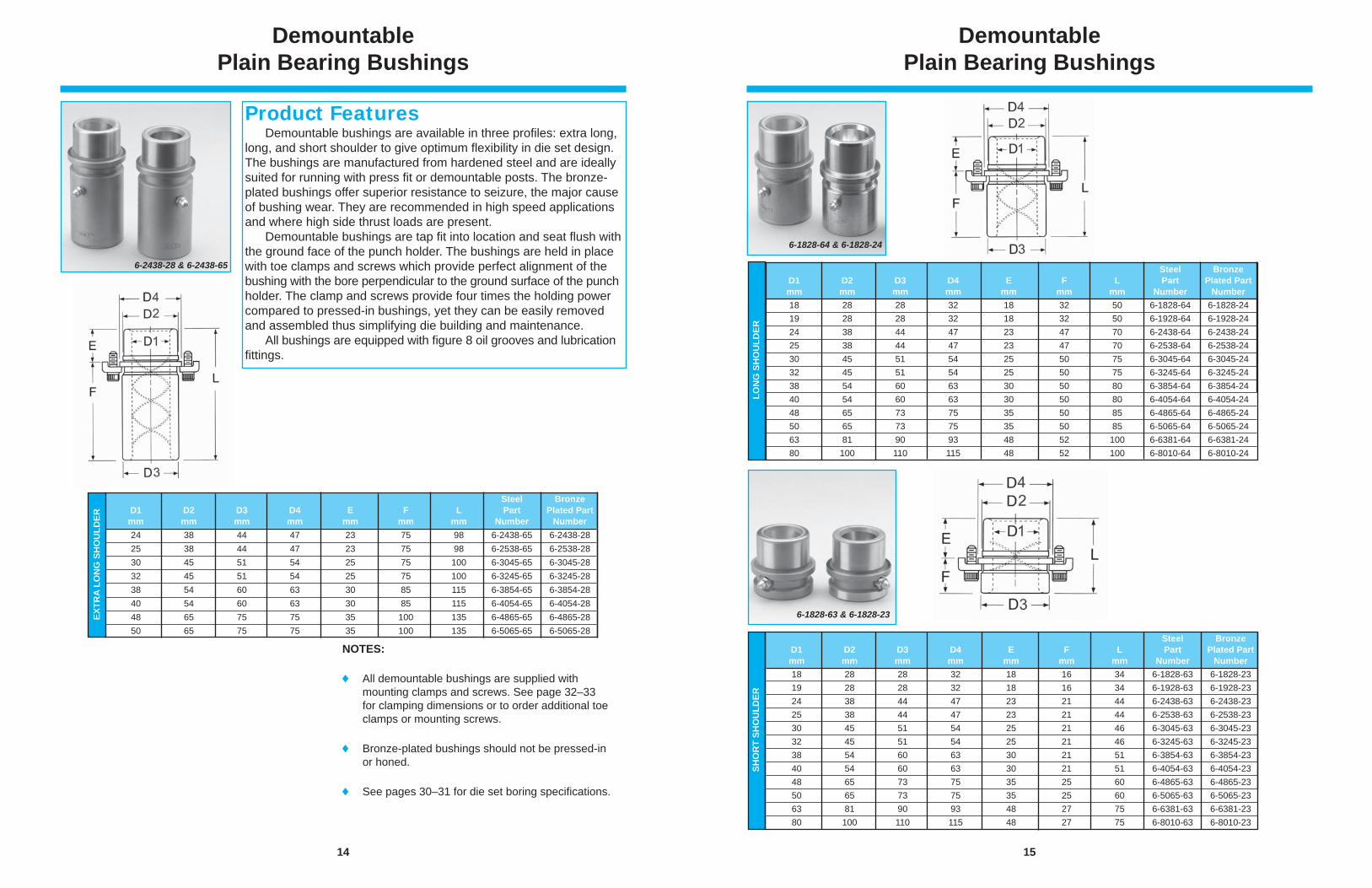
Demountable Plain Bearing Bushings
Demountable bushings are available in three profi les: extra long, long, and short shoulder to give optimum fl exibility in die set design. The bushings are manufactured from hardened steel and are ideally suited for running with press fi t or demountable posts. The bronze-plated bushings offer superior resistance to seizure, the major cause of bushing wear. They are recommended in high speed applications and where high side thrust loads are present. Demountable bushings are tap fi t into location and seat fl ush with the ground face of the punch holder. The bushings are held in place with toe clamps and screws which provide perfect alignment of the bushing with the bore perpendicular to the ground surface of the punch holder. The clamp and screws provide four times the holding power compared to pressed-in bushings, yet they can be easily removed and assembled thus simplifying die building and maintenance. All bushings are equipped with fi gure 8 oil grooves and lubrication fi ttings.
Product Features
6-2438-28 & 6-2438-65
EXTR
A LO
NG
SH
OU
LDER
Steel Bronze D1 D2 D3 D4 E F L Part Plated Part mm mm mm mm mm mm mm Number Number 24 38 44 47 23 75 98 6-2438-65 6-2438-28 25 38 44 47 23 75 98 6-2538-65 6-2538-28 30 45 51 54 25 75 100 6-3045-65 6-3045-28 32 45 51 54 25 75 100 6-3245-65 6-3245-28 38 54 60 63 30 85 115 6-3854-65 6-3854-28 40 54 60 63 30 85 115 6-4054-65 6-4054-28 48 65 75 75 35 100 135 6-4865-65 6-4865-28 50 65 75 75 35 100 135 6-5065-65 6-5065-28
15
Demountable Plain Bearing Bushings
6-1828-64 & 6-1828-24
6-1828-63 & 6-1828-23
Steel Bronze D1 D2 D3 D4 E F L Part Plated Part mm mm mm mm mm mm mm Number Number 18 28 28 32 18 16 34 6-1828-63 6-1828-23 19 28 28 32 18 16 34 6-1928-63 6-1928-23 24 38 44 47 23 21 44 6-2438-63 6-2438-23 25 38 44 47 23 21 44 6-2538-63 6-2538-23 30 45 51 54 25 21 46 6-3045-63 6-3045-23 32 45 51 54 25 21 46 6-3245-63 6-3245-23 38 54 60 63 30 21 51 6-3854-63 6-3854-23 40 54 60 63 30 21 51 6-4054-63 6-4054-23 48 65 73 75 35 25 60 6-4865-63 6-4865-23 50 65 73 75 35 25 60 6-5065-63 6-5065-23 63 81 90 93 48 27 75 6-6381-63 6-6381-23 80 100 110 115 48 27 75 6-8010-63 6-8010-23
SHO
RT
SHO
ULD
ER
Steel Bronze D1 D2 D3 D4 E F L Part Plated Part mm mm mm mm mm mm mm Number Number 18 28 28 32 18 32 50 6-1828-64 6-1828-24 19 28 28 32 18 32 50 6-1928-64 6-1928-24 24 38 44 47 23 47 70 6-2438-64 6-2438-24 25 38 44 47 23 47 70 6-2538-64 6-2538-24 30 45 51 54 25 50 75 6-3045-64 6-3045-24 32 45 51 54 25 50 75 6-3245-64 6-3245-24 38 54 60 63 30 50 80 6-3854-64 6-3854-24 40 54 60 63 30 50 80 6-4054-64 6-4054-24 48 65 73 75 35 50 85 6-4865-64 6-4865-24 50 65 73 75 35 50 85 6-5065-64 6-5065-24 63 81 90 93 48 52 100 6-6381-64 6-6381-24 80 100 110 115 48 52 100 6-8010-64 6-8010-24
LON
G S
HO
ULD
ER
16
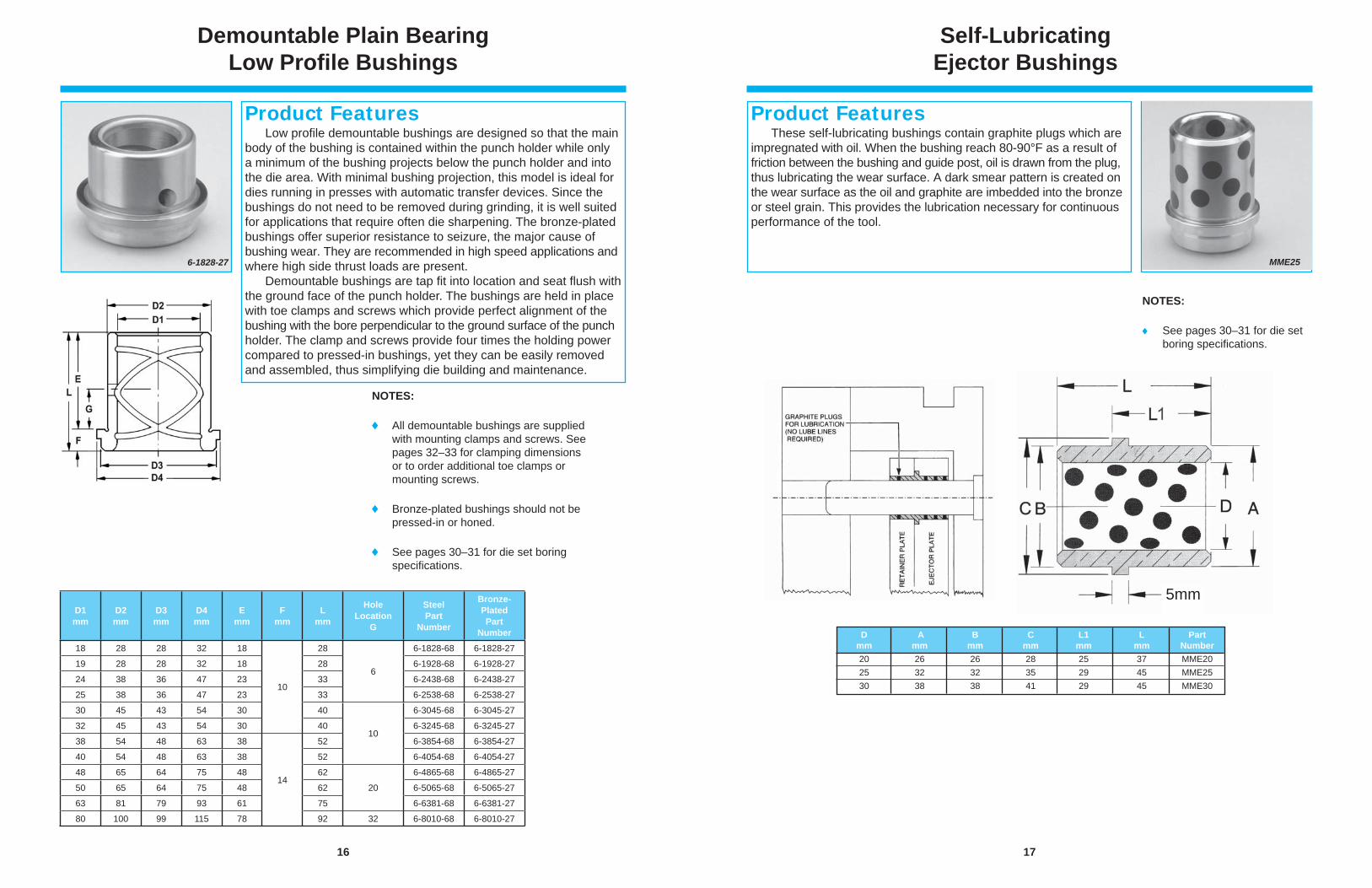
Low profi le demountable bushings are designed so that the main body of the bushing is contained within the punch holder while only a minimum of the bushing projects below the punch holder and into the die area. With minimal bushing projection, this model is ideal for dies running in presses with automatic transfer devices. Since the bushings do not need to be removed during grinding, it is well suited for applications that require often die sharpening. The bronze-plated bushings offer superior resistance to seizure, the major cause of bushing wear. They are recommended in high speed applications and where high side thrust loads are present. Demountable bushings are tap fi t into location and seat fl ush with the ground face of the punch holder. The bushings are held in place with toe clamps and screws which provide perfect alignment of the bushing with the bore perpendicular to the ground surface of the punch holder. The clamp and screws provide four times the holding power compared to pressed-in bushings, yet they can be easily removed and assembled, thus simplifying die building and maintenance.
6-1828-27
Product Features
Demountable Plain Bearing Low Profi le Bushings
NOTES:
All demountable bushings are supplied with mounting clamps and screws. See pages 32–33 for clamping dimensions or to order additional toe clamps or mounting screws.
Bronze-plated bushings should not be pressed-in or honed.
See pages 30–31 for die set boring specifi cations.
D1mm
D2mm
D3mm
D4mm
E mm
F mm
Lmm
HoleLocation
G
SteelPart
Number
Bronze-Plated Part
Number18 28 28 32 18
10
28
6
6-1828-68 6-1828-27
19 28 28 32 18 28 6-1928-68 6-1928-27
24 38 36 47 23 33 6-2438-68 6-2438-27
25 38 36 47 23 33 6-2538-68 6-2538-27
30 45 43 54 30 40
10
6-3045-68 6-3045-27
32 45 43 54 30 40 6-3245-68 6-3245-27
38 54 48 63 38
14
52 6-3854-68 6-3854-27
40 54 48 63 38 52 6-4054-68 6-4054-27
48 65 64 75 48 62
20
6-4865-68 6-4865-27
50 65 64 75 48 62 6-5065-68 6-5065-27
63 81 79 93 61 75 6-6381-68 6-6381-27
80 100 99 115 78 92 32 6-8010-68 6-8010-27
17
Self-Lubricating Ejector Bushings
NOTES:
See pages 30–31 for die set boring specifi cations.
These self-lubricating bushings contain graphite plugs which are impregnated with oil. When the bushing reach 80-90°F as a result of friction between the bushing and guide post, oil is drawn from the plug, thus lubricating the wear surface. A dark smear pattern is created on the wear surface as the oil and graphite are imbedded into the bronze or steel grain. This provides the lubrication necessary for continuous performance of the tool.
Product Features
5mm
D A B C L1 L Part mm mm mm mm mm mm Number 20 26 26 28 25 37 MME20 25 32 32 35 29 45 MME25 30 38 38 41 29 45 MME30
MME25
18
Ball Bearing Cages
6-3203-81
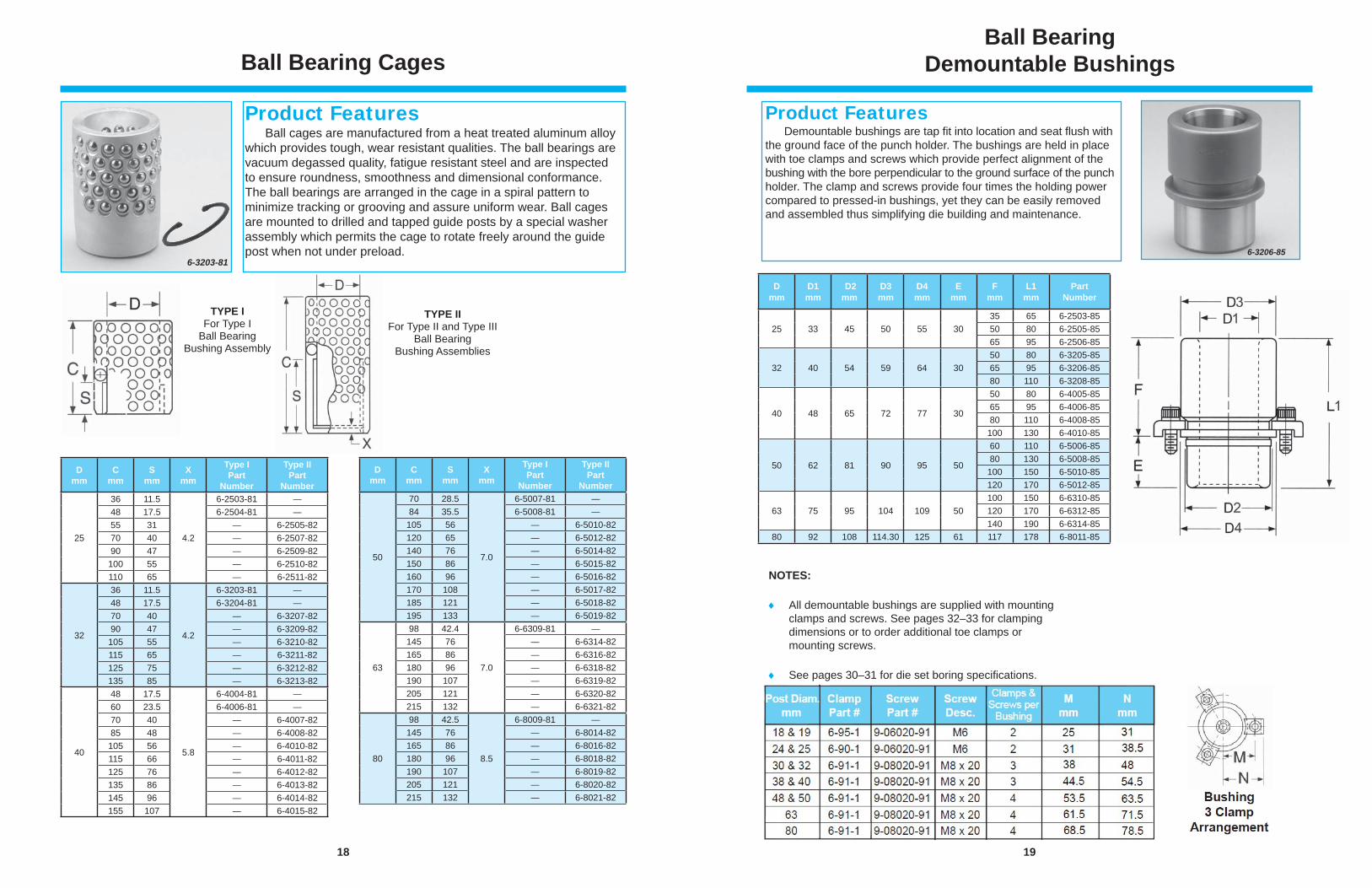
Ball cages are manufactured from a heat treated aluminum alloy which provides tough, wear resistant qualities. The ball bearings are vacuum degassed quality, fatigue resistant steel and are inspected to ensure roundness, smoothness and dimensional conformance. The ball bearings are arranged in the cage in a spiral pattern to minimize tracking or grooving and assure uniform wear. Ball cages are mounted to drilled and tapped guide posts by a special washer assembly which permits the cage to rotate freely around the guide post when not under preload.
Product Features
TYPE IFor Type I
Ball BearingBushing Assembly
TYPE IIFor Type II and Type III
Ball BearingBushing Assemblies
Dmm
Cmm
Smm
Xmm
Type IPart
Number
Type IIPart
Number
25
36 11.5
4.2
6-2503-81 —48 17.5 6-2504-81 —55 31 — 6-2505-8270 40 — 6-2507-8290 47 — 6-2509-82100 55 — 6-2510-82110 65 — 6-2511-82
32
36 11.5
4.2
6-3203-81 —48 17.5 6-3204-81 —70 40 — 6-3207-8290 47 — 6-3209-82105 55 — 6-3210-82115 65 — 6-3211-82125 75 — 6-3212-82135 85 — 6-3213-82
40
48 17.5
5.8
6-4004-81 —60 23.5 6-4006-81 —70 40 — 6-4007-8285 48 — 6-4008-82105 56 — 6-4010-82115 66 — 6-4011-82125 76 — 6-4012-82135 86 — 6-4013-82145 96 — 6-4014-82155 107 — 6-4015-82
Dmm
Cmm
Smm
Xmm
Type IPart
Number
Type IIPart
Number
50
70 28.5
7.0
6-5007-81 —84 35.5 6-5008-81 —
105 56 — 6-5010-82120 65 — 6-5012-82140 76 — 6-5014-82150 86 — 6-5015-82160 96 — 6-5016-82170 108 — 6-5017-82185 121 — 6-5018-82195 133 — 6-5019-82
63
98 42.4
7.0
6-6309-81 —145 76 — 6-6314-82165 86 — 6-6316-82180 96 — 6-6318-82190 107 — 6-6319-82205 121 — 6-6320-82215 132 — 6-6321-82
80
98 42.5
8.5
6-8009-81 —145 76 — 6-8014-82165 86 — 6-8016-82180 96 — 6-8018-82190 107 — 6-8019-82205 121 — 6-8020-82215 132 — 6-8021-82
19
Ball BearingDemountable Bushings
NOTES:
All demountable bushings are supplied with mounting clamps and screws. See pages 32–33 for clamping dimensions or to order additional toe clamps or mounting screws.
See pages 30–31 for die set boring specifi cations.
Demountable bushings are tap fi t into location and seat fl ush with the ground face of the punch holder. The bushings are held in place with toe clamps and screws which provide perfect alignment of the bushing with the bore perpendicular to the ground surface of the punch holder. The clamp and screws provide four times the holding power compared to pressed-in bushings, yet they can be easily removed and assembled thus simplifying die building and maintenance.
Product Features
6-3206-85
Dmm
D1 mm
D2 mm
D3mm
D4mm
E mm
F mm
L1 mm
PartNumber
25 33 45 50 55 3035 65 6-2503-8550 80 6-2505-8565 95 6-2506-85
32 40 54 59 64 3050 80 6-3205-8565 95 6-3206-8580 110 6-3208-85
40 48 65 72 77 30
50 80 6-4005-8565 95 6-4006-8580 110 6-4008-85100 130 6-4010-85
50 62 81 90 95 50
60 110 6-5006-8580 130 6-5008-85100 150 6-5010-85120 170 6-5012-85
63 75 95 104 109 50100 150 6-6310-85120 170 6-6312-85140 190 6-6314-85
80 92 108 114.30 125 61 117 178 6-8011-85
20
Ball Bearing Straight Sleeve Bushings
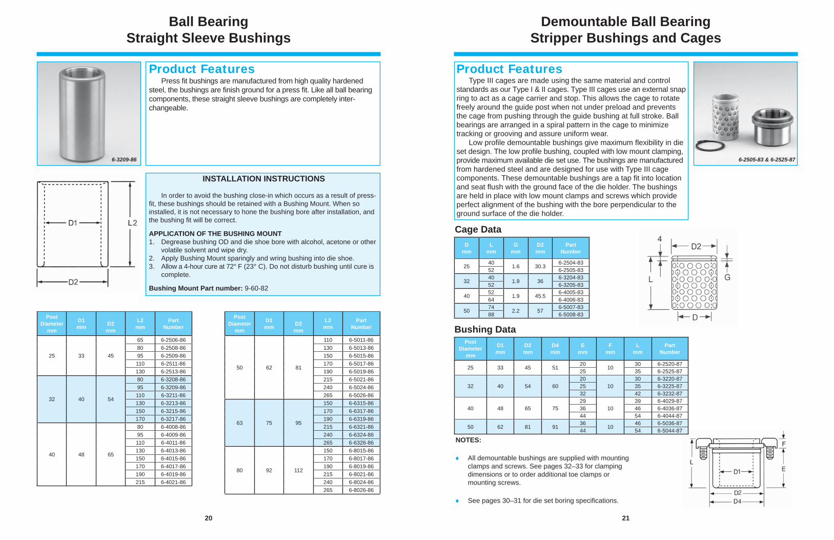
Press fi t bushings are manufactured from high quality hardened steel, the bushings are fi nish ground for a press fi t. Like all ball bearing components, these straight sleeve bushings are completely inter-changeable.
Product Features
6-3209-86
INSTALLATION INSTRUCTIONS
In order to avoid the bushing close-in which occurs as a result of press-fi t, these bushings should be retained with a Bushing Mount. When so installed, it is not necessary to hone the bushing bore after installation, and the bushing fi t will be correct.
APPLICATION OF THE BUSHING MOUNT1. Degrease bushing OD and die shoe bore with alcohol, acetone or other volatile solvent and wipe dry.2. Apply Bushing Mount sparingly and wring bushing into die shoe.3. Allow a 4-hour cure at 72° F (23° C). Do not disturb bushing until cure is complete.
Bushing Mount Part number: 9-60-82
PostDiameter
mm
D1 mm
D2mm
L2mm
Part Number
25 33 45
65 6-2506-8680 6-2508-8695 6-2509-86110 6-2511-86130 6-2513-86
32 40 54
80 6-3208-8695 6-3209-86110 6-3211-86130 6-3213-86150 6-3215-86170 6-3217-86
40 48 65
80 6-4008-8695 6-4009-86110 6-4011-86130 6-4013-86150 6-4015-86170 6-4017-86190 6-4019-86215 6-4021-86
PostDiameter
mm
D1 mm
D2mm
L2mm
Part Number
50 62 81
110 6-5011-86130 6-5013-86150 6-5015-86170 6-5017-86190 6-5019-86215 6-5021-86240 6-5024-86265 6-5026-86
63 75 95
150 6-6315-86170 6-6317-86190 6-6319-86215 6-6321-86240 6-6324-86265 6-6326-86
80 92 112
150 6-8015-86170 6-8017-86190 6-8019-86215 6-8021-86240 6-8024-86265 6-8026-86
21
Demountable Ball Bearing Stripper Bushings and Cages
Product Features
6-2505-83 & 6-2525-87
Cage Data
Bushing Data
NOTES:
All demountable bushings are supplied with mounting clamps and screws. See pages 32–33 for clamping dimensions or to order additional toe clamps or mounting screws.
See pages 30–31 for die set boring specifi cations.
Type III cages are made using the same material and control standards as our Type I & II cages. Type III cages use an external snap ring to act as a cage carrier and stop. This allows the cage to rotate freely around the guide post when not under preload and prevents the cage from pushing through the guide bushing at full stroke. Ball bearings are arranged in a spiral pattern in the cage to minimize tracking or grooving and assure uniform wear. Low profi le demountable bushings give maximum fl exibility in die set design. The low profi le bushing, coupled with low mount clamping, provide maximum available die set use. The bushings are manufactured from hardened steel and are designed for use with Type III cage components. These demountable bushings are a tap fi t into location and seat fl ush with the ground face of the die holder. The bushings are held in place with low mount clamps and screws which provide perfect alignment of the bushing with the bore perpendicular to the ground surface of the die holder.
D mm
Lmm
Gmm
D2 mm
PartNumber
2540
1.6 30.36-2504-83
52 6-2505-83
3240
1.9 366-3204-83
52 6-3205-83
4052
1.9 45.56-4005-83
64 6-4006-83
5074
2.2 576-5007-83
88 6-5008-83
PostDiameter
mm
D1mm
D2mm
D4mm
E mm
F mm
Lmm
PartNumber
25 33 45 5120
1030 6-2520-87
25 35 6-2525-87
32 40 54 6020
1030 6-3220-87
25 35 6-3225-8732 42 6-3232-87
40 48 65 7529
1039 6-4029-87
36 46 6-4036-8744 54 6-4044-87
50 62 81 9136
1046 6-5036-87
44 54 6-5044-87
22
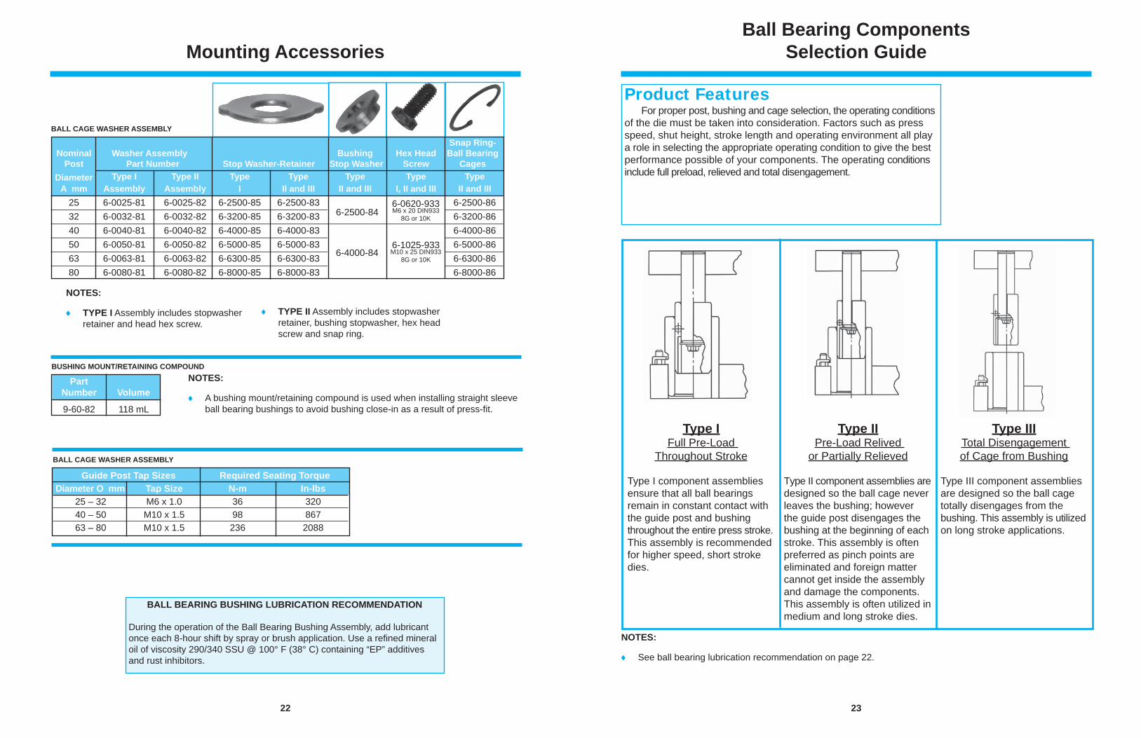
Mounting Accessories
BUSHING MOUNT/RETAINING COMPOUND
BALL CAGE WASHER ASSEMBLY
NOTES:
A bushing mount/retaining compound is used when installing straight sleeve ball bearing bushings to avoid bushing close-in as a result of press-fi t.
Part Number Volume 9-60-82 118 mL
Guide Post Tap Sizes Required Seating Torque Diameter O mm Tap Size N-m In-lbs 25 – 32 M6 x 1.0 36 320 40 – 50 M10 x 1.5 98 867 63 – 80 M10 x 1.5 236 2088
NOTES:
TYPE I Assembly includes stopwasher retainer and head hex screw.
TYPE II Assembly includes stopwasher retainer, bushing stopwasher, hex head screw and snap ring.
BALL BEARING BUSHING LUBRICATION RECOMMENDATION
During the operation of the Ball Bearing Bushing Assembly, add lubricant once each 8-hour shift by spray or brush application. Use a refi ned mineral oil of viscosity 290/340 SSU @ 100° F (38° C) containing “EP” additives and rust inhibitors.
BALL CAGE WASHER ASSEMBLY
Snap Ring- Nominal Washer Assembly Bushing Hex Head Ball Bearing Post Part Number Stop Washer-Retainer Stop Washer Screw Cages Diameter Type I Type II Type Type Type Type Type A mm Assembly Assembly I II and III II and III I, II and III II and III 25 6-0025-81 6-0025-82 6-2500-85 6-2500-83 5-0800-840 9-0506-730 6-2500-86 32 6-0032-81 6-0032-82 6-3200-85 6-3200-83 6-3200-86 40 6-0040-81 6-0040-82 6-4000-85 6-4000-83 5-1200-840 9-0607-730 6-4000-86 50 6-0050-81 6-0050-82 6-5000-85 6-5000-83 6-5000-86 63 6-0063-81 6-0063-82 6-6300-85 6-6300-83 6-6300-86 80 6-0080-81 6-0080-82 6-8000-85 6-8000-83 5-2400-840 9-0808-730 6-8000-86
6-2500-84
6-4000-84
6-0620-933M6 x 20 DIN933
8G or 10K
6-1025-933M10 x 25 DIN933
8G or 10K
23
Ball Bearing ComponentsSelection Guide
Type I Full Pre-Load
Throughout Stroke
Type I component assemblies ensure that all ball bearings remain in constant contact with the guide post and bushing throughout the entire press stroke. This assembly is recommended for higher speed, short stroke dies.
Type II Pre-Load Relived
or Partially Relieved
Type II component assemblies are designed so the ball cage never leaves the bushing; however the guide post disengages the bushing at the beginning of each stroke. This assembly is often preferred as pinch points are eliminated and foreign matter cannot get inside the assembly and damage the components. This assembly is often utilized in medium and long stroke dies.
Type III Total Disengagement of Cage from Bushing
Type III component assemblies are designed so the ball cage totally disengages from the bushing. This assembly is utilized on long stroke applications.
Product Features For proper post, bushing and cage selection, the operating conditions of the die must be taken into consideration. Factors such as press speed, shut height, stroke length and operating environment all play a role in selecting the appropriate operating condition to give the best performance possible of your components. The operating conditions include full preload, relieved and total disengagement.
NOTES:
See ball bearing lubrication recommendation on page 22.
24
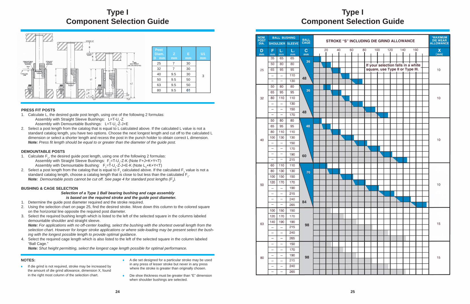
Type I Component Selection Guide
PRESS FIT POSTS 1. Calculate L, the desired guide post length, using one of the following 2 formulas: Assembly with Straight Sleeve Bushings: L=T-U1-Z Assembly with Demountable Bushings: L=T-U1-Z-J+E2. Select a post length from the catalog that is equal to L calculated above. If the calculated L value is not a
standard catalog length, you have two options. Choose the next longest length and cut off to the calculated L dimension or select a shorter length and recess the post in the punch holder to obtain correct L dimension.
Note: Press fi t length should be equal to or greater than the diameter of the guide post.
DEMOUNTABLE POSTS 1. Calculate F1, the desired guide post length, using one of the following 2 formulas: Assembly with Straight Sleeve Bushings: F1=T-U1-Z-K (Note F+J+K+Y<T) Assembly with Demountable Bushing: F1=T-U1-Z-J+E-K (Note L2+K+Y<T)2. Select a post length from the catalog that is equal to F1 calculated above. If the calculated F1 value is not a
standard catalog length, choose a catalog length that is close to but less than the calculated F1. Note: Demountable posts cannot be cut off. See page 4 for standard post lengths (F1).
BUSHING & CAGE SELECTIONSelection of a Type 1 Ball bearing bushing and cage assembly
is based on the required stroke and the guide post diameter.1. Determine the guide post diameter required and the stroke required.2. Using the selection chart on page 25, fi nd the desired stroke. Move down this column to the colored square
on the horizontal line opposite the required post diameter. 3. Select the required bushing length which is listed to the left of the selected square in the columns labeled
demountable shoulder and straight sleeve. Note: For applications with no off-center loading, select the bushing with the shortest overall length from the
selection chart. However for longer stroke applications or where side-loading may be present select the bush-ing with the longest possible length to provide optimal guidance.
4. Select the required cage length which is also listed to the left of the selected square in the column labeled “Ball Cage.”
Note: Shut height permitting, select the longest cage length possible for optimal performance.
NOTES: If die grind is not required, stroke may be increased by
the amount of die grind allowance, dimension X, found in the right most column of the selection chart.
A die set designed for a particular stroke may be used in any press of lesser stroke but never in any press where the stroke is greater than originally chosen.
Die shoe thickness must be greater than “E” dimension when shoulder bushings are selected.
Post Diam. Z E U1 D mm mm mm mm 25 7 30 32 7 30 40 9.5 30 50 9.5 50 63 9.5 50 80 9.5 50
3
25
Type I Component Selection Guide
48
36
36
70
48
48
60
84
98
98
( )
– –– –
– –– –– –
– –– –– –– –
– –– –– –– –
– –– –– –– –– –– –– –– –– –
26
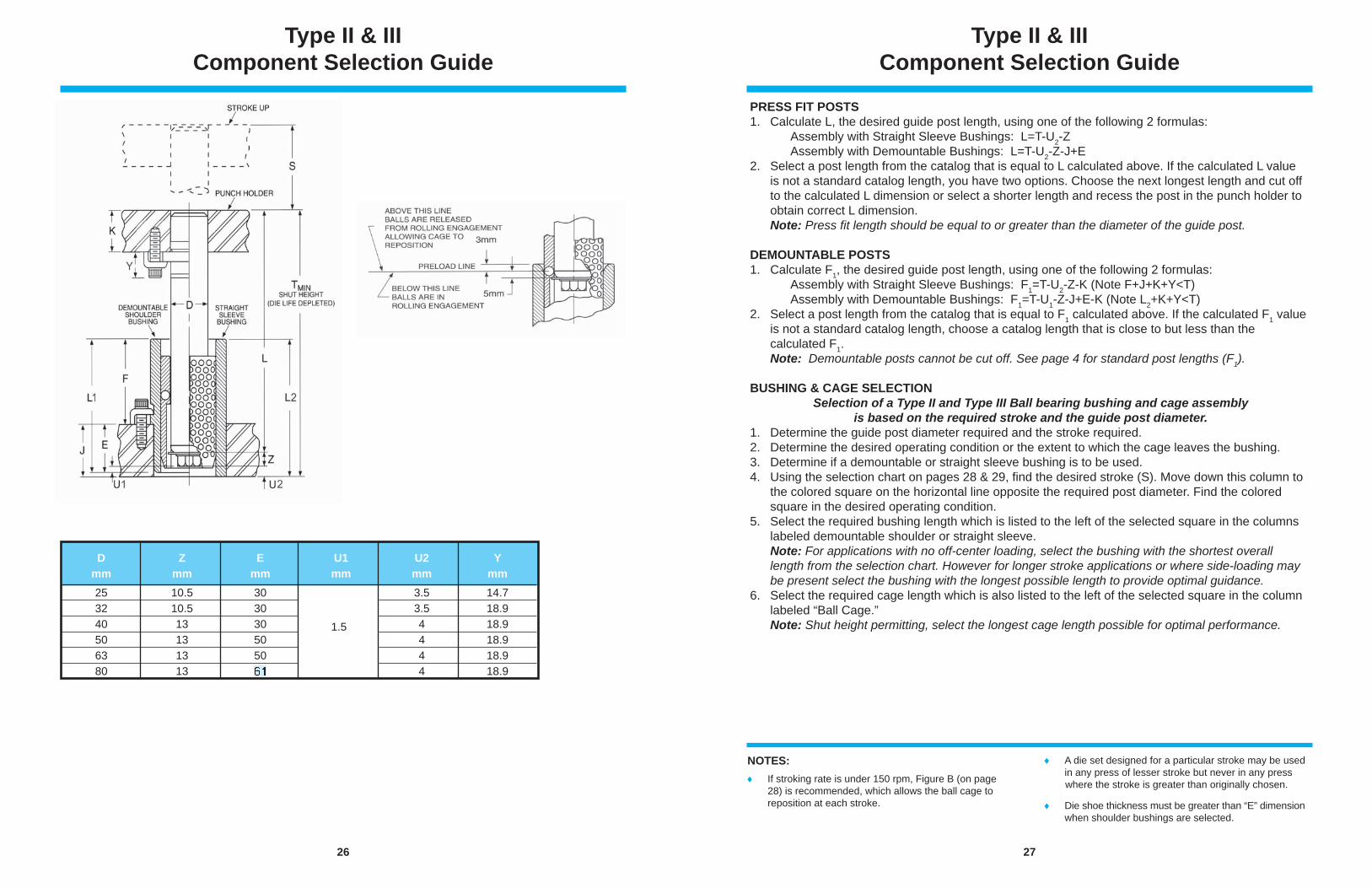
Type II & III Component Selection Guide
D Z E U1 U2 Y mm mm mm mm mm mm 25 10.5 30 3.5 14.7 32 10.5 30 3.5 18.9 40 13 30 4 18.9 50 13 50 4 18.9 63 13 50 4 18.9 80 13 50 4 18.9
1.5
27
Type II & III Component Selection Guide
PRESS FIT POSTS 1. Calculate L, the desired guide post length, using one of the following 2 formulas: Assembly with Straight Sleeve Bushings: L=T-U2-Z Assembly with Demountable Bushings: L=T-U2-Z-J+E2. Select a post length from the catalog that is equal to L calculated above. If the calculated L value is not a standard catalog length, you have two options. Choose the next longest length and cut off to the calculated L dimension or select a shorter length and recess the post in the punch holder to obtain correct L dimension. Note: Press fi t length should be equal to or greater than the diameter of the guide post.
DEMOUNTABLE POSTS 1. Calculate F1, the desired guide post length, using one of the following 2 formulas: Assembly with Straight Sleeve Bushings: F1=T-U2-Z-K (Note F+J+K+Y<T) Assembly with Demountable Bushings: F1=T-U1-Z-J+E-K (Note L2+K+Y<T)2. Select a post length from the catalog that is equal to F1 calculated above. If the calculated F1 value is not a standard catalog length, choose a catalog length that is close to but less than the calculated F1. Note: Demountable posts cannot be cut off. See page 4 for standard post lengths (F1).
BUSHING & CAGE SELECTIONSelection of a Type II and Type III Ball bearing bushing and cage assembly
is based on the required stroke and the guide post diameter.1. Determine the guide post diameter required and the stroke required.2. Determine the desired operating condition or the extent to which the cage leaves the bushing.3. Determine if a demountable or straight sleeve bushing is to be used.4. Using the selection chart on pages 28 & 29, fi nd the desired stroke (S). Move down this column to the colored square on the horizontal line opposite the required post diameter. Find the colored square in the desired operating condition. 5. Select the required bushing length which is listed to the left of the selected square in the columns labeled demountable shoulder or straight sleeve. Note: For applications with no off-center loading, select the bushing with the shortest overall length from the selection chart. However for longer stroke applications or where side-loading may be present select the bushing with the longest possible length to provide optimal guidance.6. Select the required cage length which is also listed to the left of the selected square in the column labeled “Ball Cage.” Note: Shut height permitting, select the longest cage length possible for optimal performance.
NOTES: If stroking rate is under 150 rpm, Figure B (on page
28) is recommended, which allows the ball cage to reposition at each stroke.
A die set designed for a particular stroke may be used in any press of lesser stroke but never in any press where the stroke is greater than originally chosen.
Die shoe thickness must be greater than “E” dimension when shoulder bushings are selected.
28
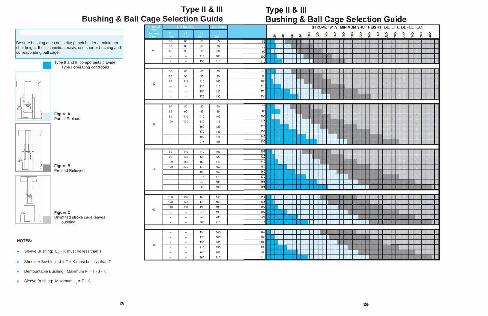
CAUTION
Be sure bushing does not strike punch holder at minimum shut height. If this condition exists, use shorter bushing and corresponding ball cage.
Type II and III components provide Type I operating conditions
Figure APartial Preload
Figure BPreload Relieved
Figure CUnlimited stroke cage leaves bushing
NOTES:
Sleeve Bushing: L2 + K must be less than T
Shoulder Bushing: J + F + K must be less than T
Demountable Bushing: Maximum F = T - J - K
Sleeve Bushing: Maximum L2 = T - K
Type II & III Bushing & Ball Cage Selection Guide
1 35 65 65 55
50 80 80 70
65 95 95 90
– – 110 100
– – 130 110
50 80 80 70
1 1/4 65 95 95 90
80 110 110 105
– – 130 115
– – 150 125
– – 170 135
1 1/2 50 80 80 70
65 95 95 85
80 110 110 105
100 130 130 115
– – 150 125
– – 170 135
– – 190 145
– – 215 155
1 3/4 60 110 110 105
80 130 130 120
100 150 150 140
120 170 170 150
– – 190 160
– – 215 170
– – 240 185
265 195
100 150 150 145
120 170 170 165
140 190 190 180
– – 215 190
– – 240 205
– – 265 215
– – 150 145
2 1/2 – – 170 165
– – 190 180
– – 215 190
– – 240 205
– – 265 215
Nominal Ball Bushing Ball CagePost
Diameter F L1 L2 CD (mm) (mm) (mm) (mm) (mm)
25
32
40
50
63
80
30
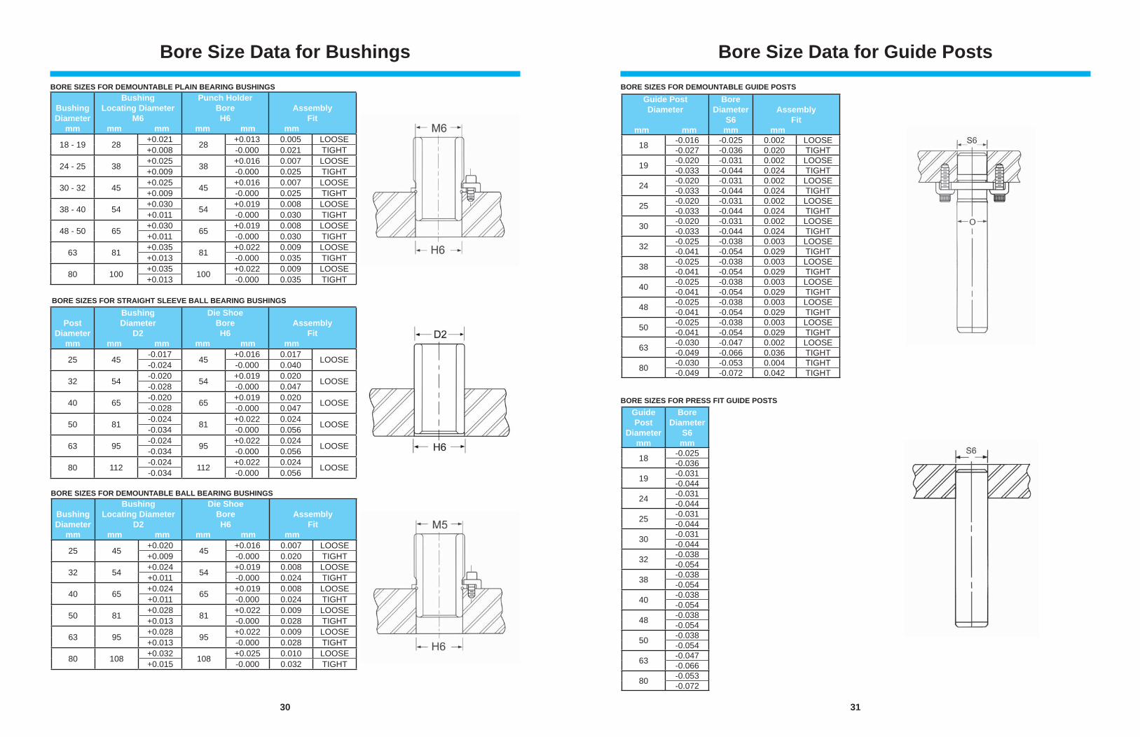
Bore Size Data for Bushings
BORE SIZES FOR STRAIGHT SLEEVE BALL BEARING BUSHINGS
BORE SIZES FOR DEMOUNTABLE PLAIN BEARING BUSHINGS
BORE SIZES FOR DEMOUNTABLE BALL BEARING BUSHINGS
BushingDiameter
mm
BushingLocating Diameter
M6mm mm
Punch HolderBoreH6
mm mm
AssemblyFit
mm
18 - 19 28 +0.021 28 +0.013 0.005 LOOSE+0.008 -0.000 0.021 TIGHT
24 - 25 38 +0.025 38 +0.016 0.007 LOOSE+0.009 -0.000 0.025 TIGHT
30 - 32 45 +0.025 45 +0.016 0.007 LOOSE+0.009 -0.000 0.025 TIGHT
38 - 40 54 +0.030 54 +0.019 0.008 LOOSE+0.011 -0.000 0.030 TIGHT
48 - 50 65 +0.030 65 +0.019 0.008 LOOSE+0.011 -0.000 0.030 TIGHT
63 81 +0.035 81 +0.022 0.009 LOOSE+0.013 -0.000 0.035 TIGHT
80 100 +0.035 100 +0.022 0.009 LOOSE+0.013 -0.000 0.035 TIGHT
BushingDiameter
mm
BushingLocating Diameter
D2mm mm
Die ShoeBoreH6
mm mm
AssemblyFit
mm
25 45 +0.020 45 +0.016 0.007 LOOSE+0.009 -0.000 0.020 TIGHT
32 54 +0.024 54 +0.019 0.008 LOOSE+0.011 -0.000 0.024 TIGHT
40 65 +0.024 65 +0.019 0.008 LOOSE+0.011 -0.000 0.024 TIGHT
50 81 +0.028 81 +0.022 0.009 LOOSE+0.013 -0.000 0.028 TIGHT
63 95 +0.028 95 +0.022 0.009 LOOSE+0.013 -0.000 0.028 TIGHT
80 108 +0.032 108 +0.025 0.010 LOOSE+0.015 -0.000 0.032 TIGHT
PostDiameter
mm
BushingDiameter
D2mm mm
Die ShoeBoreH6
mm mm
AssemblyFit
mm
25 45 -0.017 45 +0.016 0.017 LOOSE-0.024 -0.000 0.040
32 54 -0.020 54 +0.019 0.020 LOOSE-0.028 -0.000 0.047
40 65 -0.020 65 +0.019 0.020 LOOSE-0.028 -0.000 0.047
50 81 -0.024 81 +0.022 0.024 LOOSE-0.034 -0.000 0.056
63 95 -0.024 95 +0.022 0.024 LOOSE-0.034 -0.000 0.056
80 112 -0.024 112 +0.022 0.024 LOOSE-0.034 -0.000 0.056
31
Bore Size Data for Guide PostsBORE SIZES FOR DEMOUNTABLE GUIDE POSTS
BORE SIZES FOR PRESS FIT GUIDE POSTS
Guide PostDiameter
mm mm
Bore Diameter
S6 mm
AssemblyFit
mm
18 -0.016 -0.025 0.002 LOOSE-0.027 -0.036 0.020 TIGHT
19 -0.020 -0.031 0.002 LOOSE-0.033 -0.044 0.024 TIGHT
24 -0.020 -0.031 0.002 LOOSE-0.033 -0.044 0.024 TIGHT
25 -0.020 -0.031 0.002 LOOSE-0.033 -0.044 0.024 TIGHT
30 -0.020 -0.031 0.002 LOOSE-0.033 -0.044 0.024 TIGHT
32 -0.025 -0.038 0.003 LOOSE-0.041 -0.054 0.029 TIGHT
38 -0.025 -0.038 0.003 LOOSE-0.041 -0.054 0.029 TIGHT
40 -0.025 -0.038 0.003 LOOSE-0.041 -0.054 0.029 TIGHT
48 -0.025 -0.038 0.003 LOOSE-0.041 -0.054 0.029 TIGHT
50 -0.025 -0.038 0.003 LOOSE-0.041 -0.054 0.029 TIGHT
63 -0.030 -0.047 0.002 LOOSE-0.049 -0.066 0.036 TIGHT
80 -0.030 -0.053 0.004 TIGHT-0.049 -0.072 0.042 TIGHT
Guide Post
Diameter mm
Bore Diameter
S6 mm
18 -0.025-0.036
19 -0.031-0.044
24 -0.031-0.044
25 -0.031-0.044
30 -0.031-0.044
32 -0.038-0.054
38 -0.038-0.054
40 -0.038-0.054
48 -0.038-0.054
50 -0.038-0.054
63 -0.047-0.066
80 -0.053-0.072
32
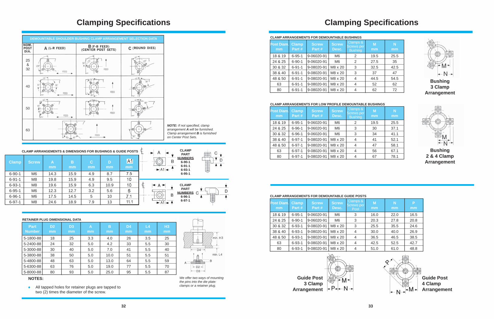
Clamping Specifi cations
DEMOUNTABLE SHOULDER BUSHING CLAMP ARRANGEMENT SELECTION DATA
NOTE: If not specifi ed, clamp arrangement A will be furnished. Clamp arrangement B is furnished on Center Post Sets.
RETAINER PLUG DIMENSIONAL DATA
Part D2 D3 A B D4 L4 H3 Number mm mm mm mm mm mm mm
5-1800-88 18 25 3.3 4.0 26 3.5 25 5-2400-88 24 32 5.0 4.2 33 5.5 30 5-3000-88 30 40 5.0 7.0 41 5.5 40 5-3800-88 38 50 5.0 10.0 51 5.5 51 5-4800-88 48 63 5.0 13.0 64 5.5 59 5-6300-88 63 76 5.0 19.0 77 5.5 70 5-8000-88 80 93 5.0 25.0 95 5.5 87
NOTES:
All tapped holes for retainer plugs are tapped to two (2) times the diameter of the screw.
We offer two ways of mounting the pins into the die plate: clamps or a retainer plug.
CLAMP ARRANGEMENTS & DIMENSIONS FOR BUSHINGS & GUIDE POSTS CLAMPPART
NUMBERS6-90-16-91-16-93-16-95-1
CLAMPPART
NUMBERS6-96-16-97-1
Clamp Screw A B C D mm mm mm mm 6-90-1 M6 14.3 15.9 4.9 8.7 6-91-1 M8 19.8 15.9 4.9 9.5 6-93-1 M8 19.6 15.9 6.3 10.9 6-95-1 M6 12.3 12.7 3.2 5.6 6-96-1 M6 17.5 14.5 5 10 6-97-1 M8 24.6 18.9 7.9 13
33
Clamping Specifi cationsCLAMP ARRANGEMENTS FOR DEMOUNTABLE BUSHINGS
CLAMP ARRANGEMENTS FOR LOW PROFILE DEMOUNTABLE BUSHINGS
CLAMP ARRANGEMENTS FOR DEMOUNTABLE GUIDE POSTS
Post Diam. Clamp Screw Screw M N mm Part # Part # Desc. mm mm
18 & 19 6-95-1 9-06020-91 M6 2 19.5 25.5 24 & 25 6-90-1 9-06020-91 M6 2 27.5 35 30 & 32 6-91-1 9-08020-91 M8 x 20 3 32.5 42.5 38 & 40 6-91-1 9-08020-91 M8 x 20 3 37 47 48 & 50 6-91-1 9-08020-91 M8 x 20 4 44.5 54.5 63 6-91-1 9-08020-91 M8 x 20 4 52 62 80 6-91-1 9-08020-91 M8 x 20 4 62 72
Clamps & Screws per
Bushing
Post Diam. Clamp Screw Screw M N mm Part # Part # Desc. mm mm
18 & 19 6-95-1 9-06020-91 M6 2 19.5 25.5 24 & 25 6-96-1 9-06020-91 M6 3 30 37.1 30 & 32 6-96-1 9-06020-91 M6 3 34 41.1 38 & 40 6-97-1 9-08020-91 M8 x 20 4 41 52.1 48 & 50 6-97-1 9-08020-91 M8 x 20 4 47 58.1 63 6-97-1 9-08020-91 M8 x 20 4 56 67.1 80 6-97-1 9-08020-91 M8 x 20 4 67 78.1
Clamps & Screws per
Bushing
Post Diam. Clamp Screw Screw M N P mm Part # Part # Desc. mm mm mm
18 & 19 6-95-1 9-06020-91 M6 3 16.0 22.0 16.5 24 & 25 6-90-1 9-06020-91 M6 3 20.3 27.8 20.8 30 & 32 6-93-1 9-08020-91 M8 x 20 3 25.5 35.5 24.6 38 & 40 6-93-1 9-08020-91 M8 x 20 4 30.0 40.0 26.9 48 & 50 6-93-1 9-08020-91 M8 x 20 4 36.5 46.5 38.5 63 6-93-1 9-08020-91 M8 x 20 4 42.5 52.5 42.7 80 6-93-1 9-08020-91 M8 x 20 4 51.0 61.0 48.8
Clamps & Screws per
Post
Guide Post3 Clamp
Arrangement
Guide Post4 Clamp Arrangement
Bushing3 Clamp
Arrangement
Bushing2 & 4 Clamp Arrangement
34
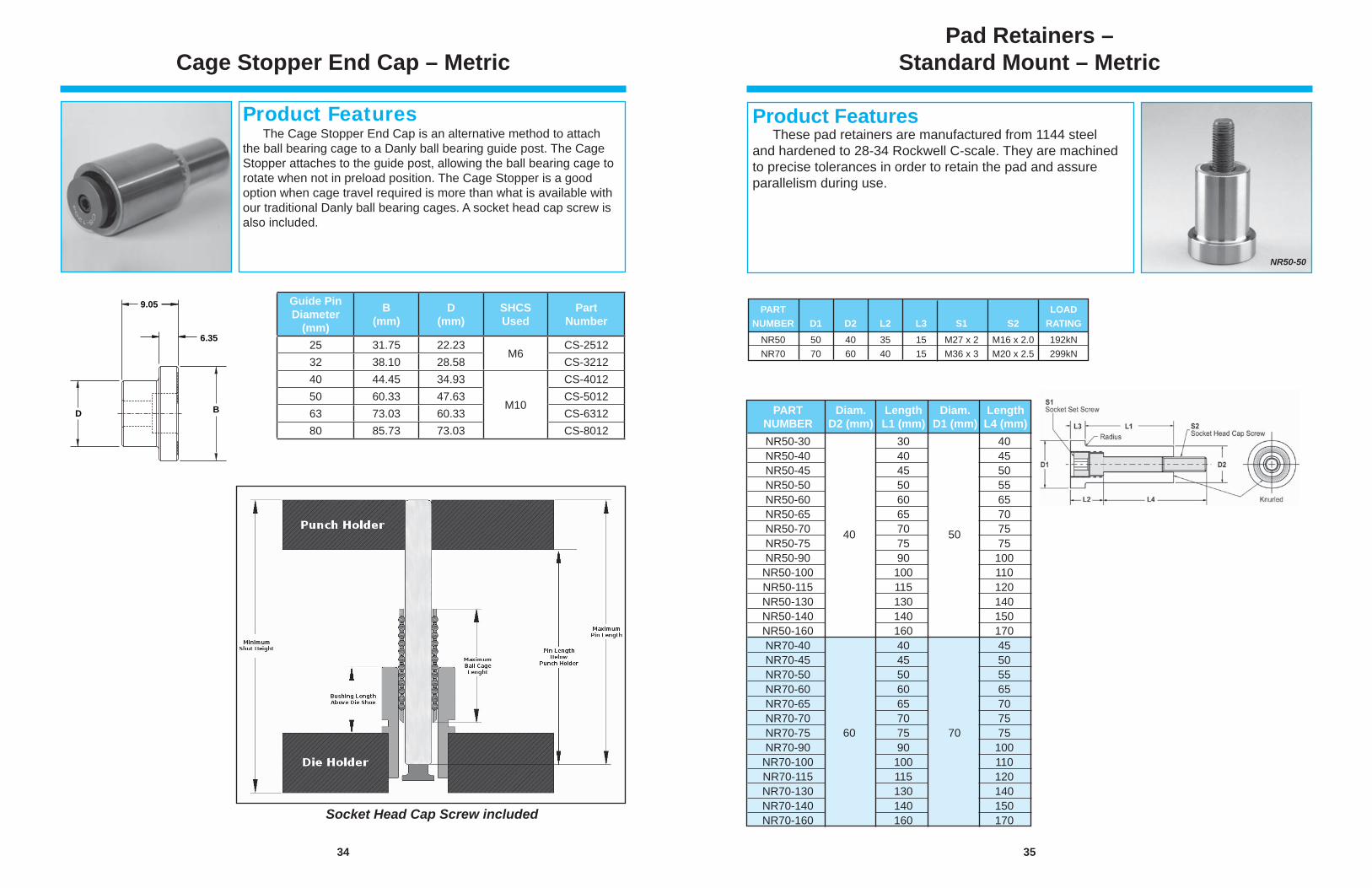
Cage Stopper End Cap – Metric
Product Features The Cage Stopper End Cap is an alternative method to attach the ball bearing cage to a Danly ball bearing guide post. The Cage Stopper attaches to the guide post, allowing the ball bearing cage to rotate when not in preload position. The Cage Stopper is a good option when cage travel required is more than what is available with our traditional Danly ball bearing cages. A socket head cap screw is also included.
D B
9.05
6.35
Socket Head Cap Screw included
Guide Pin Diameter
(mm)
B(mm)
D(mm)
SHCSUsed
Part Number
25 31.75 22.23M6
CS-251232 38.10 28.58 CS-321240 44.45 34.93
M10
CS-401250 60.33 47.63 CS-501263 73.03 60.33 CS-631280 85.73 73.03 CS-8012
35
These pad retainers are manufactured from 1144 steel and hardened to 28-34 Rockwell C-scale. They are machined to precise tolerances in order to retain the pad and assure parallelism during use.
Product Features
Pad Retainers –Standard Mount – Metric
NR50-50
NR50-30 30 40 NR50-40 40 45 NR50-45 45 50 NR50-50 50 55 NR50-60 60 65 NR50-65 65 70 NR50-70 70 75 NR50-75 75 75 NR50-90 90 100 NR50-100 100 110 NR50-115 115 120 NR50-130 130 140 NR50-140 140 150 NR50-160 160 170 NR70-40 40 45 NR70-45 45 50 NR70-50 50 55 NR70-60 60 65 NR70-65 65 70 NR70-70 70 75 NR70-75 75 75 NR70-90 90 100 NR70-100 100 110 NR70-115 115 120 NR70-130 130 140 NR70-140 140 150 NR70-160 160 170
PART Diam. Length Diam. Length NUMBER D2 (mm) L1 (mm) D1 (mm) L4 (mm)
40 50
60 70
PART LOAD NUMBER D1 D2 L2 L3 S1 S2 RATING NR50 50 40 35 15 M27 x 2 M16 x 2.0 192kN NR70 70 60 40 15 M36 x 3 M20 x 2.5 299kN
36
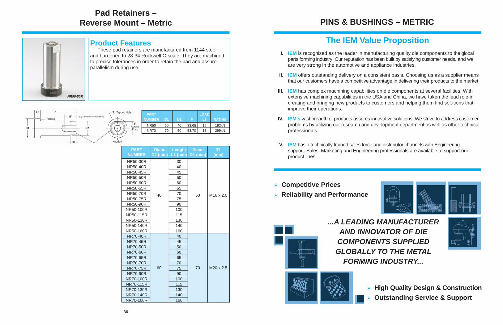
Pad Retainers –Reverse Mount – Metric
NR50-50R
These pad retainers are manufactured from 1144 steel and hardened to 28-34 Rockwell C-scale. They are machined to precise tolerances in order to retain the pad and assure parallelism during use.
Product Features
PART LOAD NUMBER D1 D2 F L3 RATING NR50 50 40 33.65 15 192kN NR70 70 60 53.70 15 299kN
NR50-30R 30 NR50-40R 40 45 NR50-45R 45 NR50-50R 50 55 NR50-60R 60 NR50-65R 65 NR50-70R 70 NR50-75R 75 NR50-90R 90 NR50-100R 100 NR50-115R 115 NR50-130R 130 NR50-140R 140 NR50-160R 160 NR70-40R 40 NR70-45R 45 NR70-50R 50 NR70-60R 60 NR70-65R 65 NR70-70R 70 NR70-75R 75 NR70-90R 90 NR70-100R 100 NR70-115R 115 NR70-130R 130 NR70-140R 140 NR70-160R 160
PART Diam. Length Diam. T1 NUMBER D2 (mm) L1 (mm) D1 (mm) (mm)
40 50 M16 x 2.0
60 70 M20 x 2.5
PINS & BUSHINGS – METRIC
The IEM Value Proposition I. IEM is recognized as the leader in manufacturing quality die components to the global parts forming industry. Our reputation has been built by satisfying customer needs, and we are very strong in the automotive and appliance industries.
II. IEM offers outstanding delivery on a consistent basis. Choosing us as a supplier means that our customers have a competitive advantage in delivering their products to the market.
III. IEM has complex machining capabilities on die components at several facilities. With extensive machining capabilities in the USA and China, we have taken the lead role in creating and bringing new products to customers and helping them fi nd solutions that improve their operations.
IV. IEM’s vast breadth of products assures innovative solutions. We strive to address customer problems by utilizing our research and development department as well as other technical professionals.
V. IEM has a technically trained sales force and distributor channels with Engineering support. Sales, Marketing and Engineering professionals are available to support our product lines.
...A LEADING MANUFACTURER AND INNOVATOR OF DIE
COMPONENTS SUPPLIED GLOBALLY TO THE METAL
FORMING INDUSTRY...
Competitive PricesReliability and Performance
High Quality Design & ConstructionOutstanding Service & Support
PINS & BUSHINGS - METRIC
© 2012 IEM. All rights reserved. DS562-A4 (W) 11/12A Misumi Group
Distributed by:
WITHIN THE USA & CANADA CALL: 800-652-6462FAX: 800-406-4410
OUTSIDE THE USA & CANADA CALL: 001-248-489-7816FAX: 001-248-553-6842