pimrc and mobile communications the next 25 yearspimrc2014.ieee-pimrc.org/pimrc-2014 - intel...
TRANSCRIPT

PIMRC and Mobile Communications The Next 25 Years
Dr. Kenneth Stewart, Intel PIMRC 2014 4 September 2014 Washington DC
The opinions expressed are those of Dr. Kenneth Stewart and may not reflect the opinions, conclusions or technical position of Intel Corp. or its affiliates. *Other names and brands may be claimed as the property of others DO NOT FORWARD
“I always avoid prophesying beforehand because it is much better to prophesy after the event has already taken place”
Winston Churchill
PIMRC 2014 2
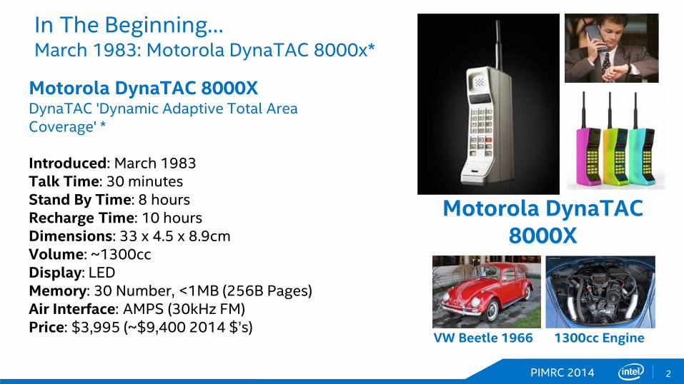
In The Beginning… March 1983: Motorola DynaTAC 8000x*
Motorola DynaTAC 8000X DynaTAC 'Dynamic Adaptive Total Area Coverage' * Introduced: March 1983 Talk Time: 30 minutes Stand By Time: 8 hours Recharge Time: 10 hours Dimensions: 33 x 4.5 x 8.9cm Volume: ~1300cc Display: LED Memory: 30 Number, <1MB (256B Pages) Air Interface: AMPS (30kHz FM) Price: $3,995 (~$9,400 2014 $’s)
Motorola DynaTAC 8000X
VW Beetle 1966 1300cc Engine
PIMRC 2014 3
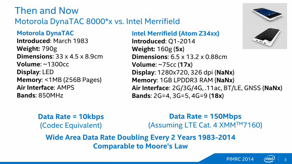
Then and Now Motorola DynaTAC 8000*x vs. Intel Merrifield Motorola DynaTAC Introduced: March 1983 Weight: 790g Dimensions: 33 x 4.5 x 8.9cm Volume: ~1300cc Display: LED Memory: <1MB (256B Pages) Air Interface: AMPS Bands: 850MHz
Intel Merrifield (Atom Z34xx) Introduced: Q1-2014 Weight: 160g (5x) Dimensions: 6.5 x 13.2 x 0.88cm Volume: ~75cc (17x) Display: 1280x720, 326 dpi (NaNx) Memory: 1GB LPDDR3 RAM (NaNx) Air Interface: 2G/3G/4G, .11ac, BT/LE, GNSS (NaNx) Bands: 2G=4, 3G=5, 4G=9 (18x)
Data Rate = 10kbps (Codec Equivalent)
Data Rate = 150Mbps (Assuming LTE Cat. 4 XMMTM7160)
Wide Area Data Rate Doubling Every 2 Years 1983-2014 Comparable to Moore’s Law
PIMRC 2014 4
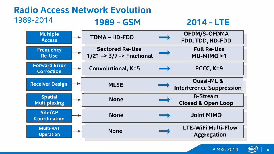
Radio Access Network Evolution 1989-2014
OFDM/S-OFDMAFDD, TDD, HD-FDDTDMA – HD-FDD
1989 - GSM 2014 - LTE
Sectored Re-Use 1/21 –> 3/7 -> Fractional
Full Re-UseMU-MIMO >1
Convolutional, K=5 PCCC, K=9
None 8-StreamClosed & Open Loop
None Joint MIMO
None LTE-WiFi Multi-Flow Aggregation
MultipleAccess
FrequencyRe-Use
Forward Error Correction
Spatial Multiplexing
Site/AP Coordination
Multi-RAT Operation
MLSEReceiver Design Quasi-ML &Interference Suppression
PIMRC 2014 5
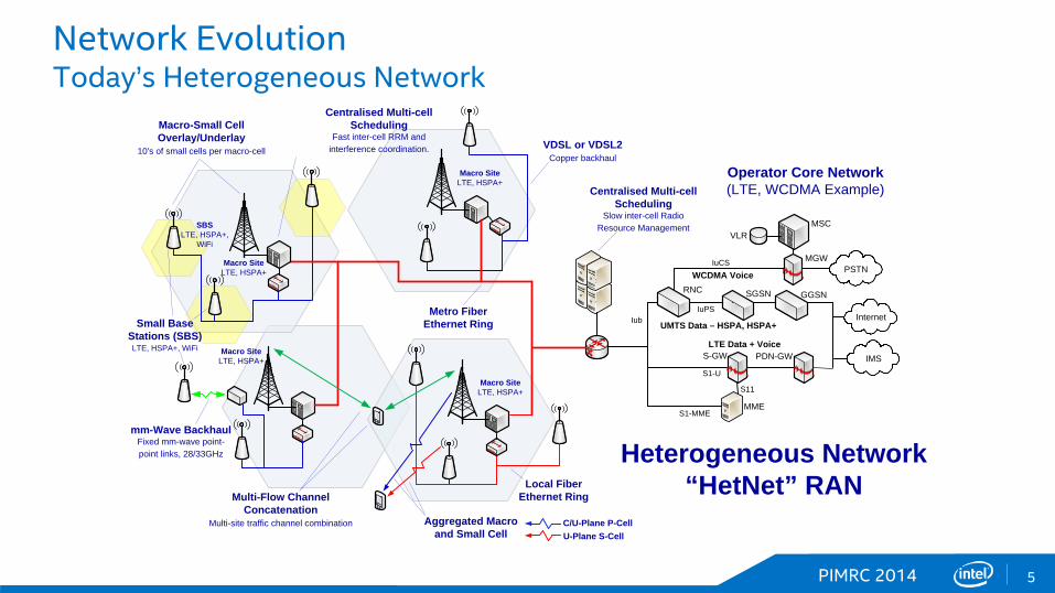
Network Evolution Today’s Heterogeneous Network
Small Base Stations (SBS)LTE, HSPA+, WiFi
Macro SiteLTE, HSPA+
Metro Fiber Ethernet Ring
Macro SiteLTE, HSPA+
Macro SiteLTE, HSPA+
VDSL or VDSL2Copper backhaul
Local Fiber Ethernet Ring
mm-Wave BackhaulFixed mm-wave point-point links, 28/33GHz Heterogeneous Network
“HetNet” RAN
Centralised Multi-cell Scheduling
Slow inter-cell Radio Resource ManagementSBS
LTE, HSPA+, WiFi
IuPS
IuCS
Iub
PSTN
Internet
IMSS1-U
S1-MME
S11
UMTS Data – HSPA, HSPA+
WCDMA Voice
LTE Data + Voice
MME
S-GW PDN-GW
GGSNSGSNRNC
MSCVLR
MGW
Operator Core Network(LTE, WCDMA Example)
C/U-Plane P-CellU-Plane S-Cell
Aggregated Macroand Small Cell
Macro-Small CellOverlay/Underlay
10's of small cells per macro-cell
Centralised Multi-cell Scheduling
Fast inter-cell RRM and interference coordination.
Multi-Flow Channel Concatenation
Multi-site traffic channel combination
Macro SiteLTE, HSPA+

PIMRC 2014 6
Network Evolution Virtualization and Coordinated or Distributed RAN
Multi-RAT Baseband Unit (BBU)Multi-RAT: LTE (FDD/TDD), HSPA+
Baseband signal processing resource shared between 10's or 100's of logical cells
Distributed (‘C’) Radio Access Network (‘C’-RAN)
Centralised SchedulerFast scheduler, inc.
interference coordinationCPRI Fiber Distribution
Dark or operator fiber – Multi- λ CWDM/DWDM, Tbps Backhaul
Multi-Band Remote Radio Head (RRH)
Full-band, multi-band operation, arbitrary waveform transmission
Band 1
Band 3
WCDMA/HSPA+ SISO
CDMA 1xRTT, 1xEVDO SISO
LTE MIMO
RAT-Specific Site Re-use
Star Topology
Cascade Topology
IuPS
IuCS
Iub
PSTN
Internet
IMSS1-U
S1-MME
S11
UMTS Data – HSPA, HSPA+
WCDMA Voice
LTE Data + Voice
MME
S-GW PDN-GW
GGSNSGSNRNC
MSCVLR
MGW
Virtualized Core Network(LTE, WCDMA Example)
Processing HubEnterprise core, central office, stadium or venue
Band 1
Band 3
Band 2
PIMRC 2014 7
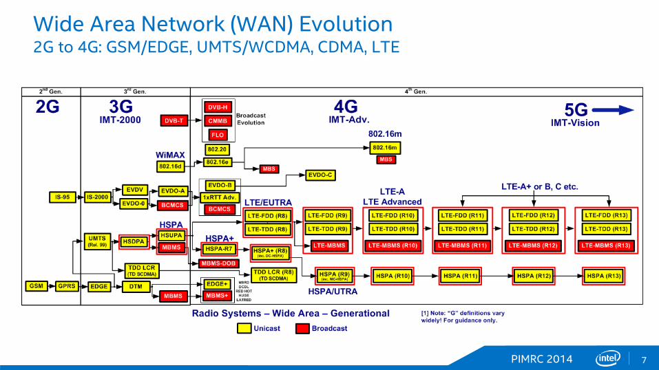
Wide Area Network (WAN) Evolution 2G to 4G: GSM/EDGE, UMTS/WCDMA, CDMA, LTE
PIMRC 2014 8
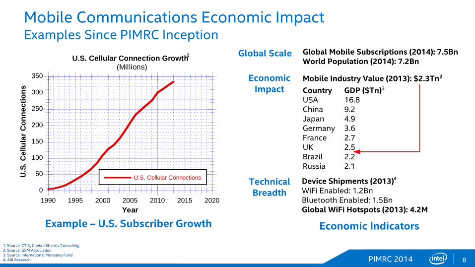
Mobile Communications Economic Impact Examples Since PIMRC Inception
1. Source: CTIA, Chetan Sharma Consulting 2. Source: GSM Association 3. Source: International Monetary Fund 4. ABI Research
Example – U.S. Subscriber Growth Economic Indicators
0
50
100
150
200
250
300
350
1990 1995 2000 2005 2010 2015 2020
U.S. Cellular Connection Growth1
(Millions)
U.S. Cellular ConnectionsU.S
. Cel
lula
r Con
nect
ions
Year
Global Scale Global Mobile Subscriptions (2014): 7.5BnWorld Population (2014): 7.2Bn
Economic Impact
Mobile Industry Value (2013): $2.3Tn2
CountryUSAChinaJapanGermanyFranceUKBrazilRussia
GDP ($Tn)3
16.89.24.93.62.72.52.22.1
Technical Breadth
Device Shipments (2013)4
WiFi Enabled: 1.2BnBluetooth Enabled: 1.5BnGlobal WiFi Hotspots (2013): 4.2M
PIMRC 2014 9
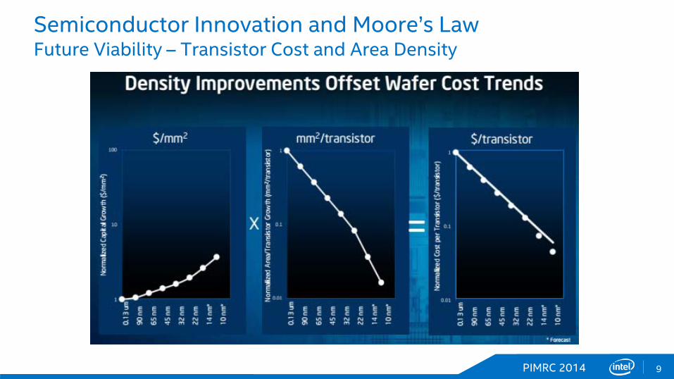
Semiconductor Innovation and Moore’s Law Future Viability – Transistor Cost and Area Density
PIMRC 2014 10
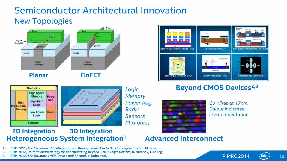
Semiconductor Architectural Innovation New Topologies
2D Integration 3D Integration
Logic Memory Power Reg. Radio Sensors Photonics
Heterogeneous System Integration1
1. IEDM 2011, The Evolution of Scaling from the Homogeneous Era to the Heterogeneous Era, M. Bohr 2. IEDM 2012, Uniform Methodology for Benchmarking Beyond-CMOS Logic Devices, D. Nikonov, I. Young 3. IEDM 2012, The Ultimate CMOS Device and Beyond, K. Kuhn et al.
Beyond CMOS Devices2,3
Advanced Interconnect
Cu Wires at 17nm. Colour indicates crystal orientation.
Planar FinFET
PIMRC 2014 11
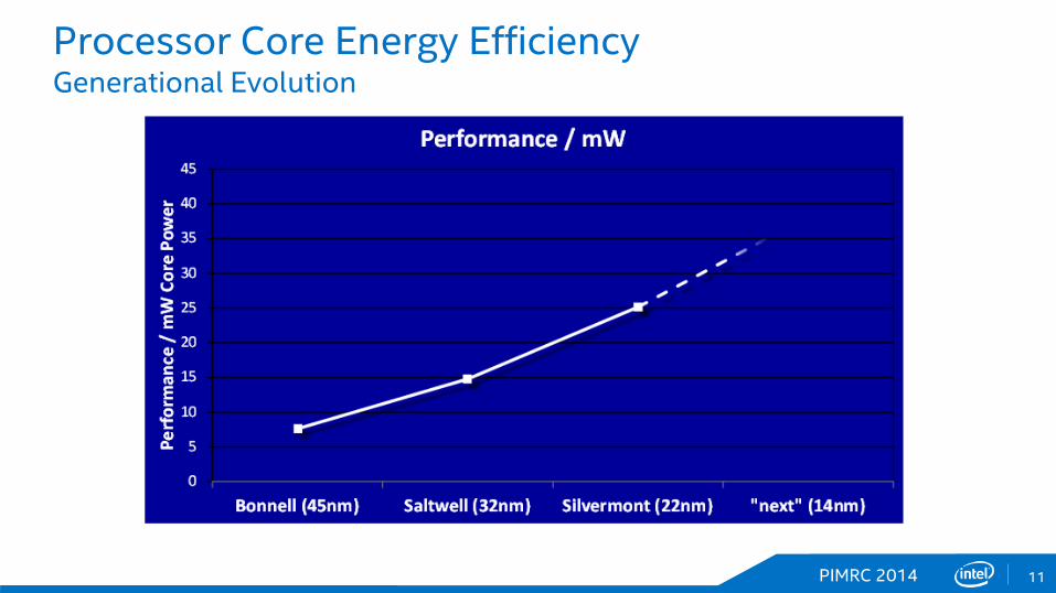
Processor Core Energy Efficiency Generational Evolution

PIMRC 2014 12
Network Design Evolution Key Enablers for Next-Generation Network Performance
System Densification
Advanced Source Coding
Enhanced Spectral Efficiency
New Spectrum Hz
nodes/km2
bps/Hz/node
bps/km2Network Performance
• Small Cells, Radio Heads, HetNet• NNT – New Network Topologies• AIS – Advanced Interference Suppression
• Sub-6GHz and mm-Wave• LSA/SAS, White-Space, Unlicensed• Inter-RAT Aggregation – WiFi, WiGig, LTE
• H.265, EVS, Optimal Scheduling• MMIMO and Non-Orthogonal Modulation• Next-generation Codes• Multi-Flow Node Aggregation
Hz nodes/km2 bps/Hz/node bps/km2
Fundamental Network KPI = Capacity per Unit Area

PIMRC 2014 13
Adding to the Spectrum Pool New Bands, Flexible Sharing

PIMRC 2014 14
Advanced Receiver Evolution Interference Management, HetNets and Higher Frequency Re-use
Note 1: Multiple non-standardized and proprietary techniques have been deployed in commercial implementations. Note 2: RAT – Radio Access Technology Note 3: SIC - Successive Interference Cancellation
Year Standard Technique1 RAT2 Description
2003 SAIC GSM Single Antenna Interference Cancellation (SAIC), single interferer suppressed by exploiting GMSK constellation redundancy.
2003 UMTS Type 2 HSPA Single antenna equalizer replaces RAKE receiver.
2006 DARP GSM Extends SAIC to dual-antennas (“Rx diversity”) at the device.
2006 UMTS Type 2i HSPA Single antenna equalizer with dominant interferer interference suppression (usually single cell), usually SIC3 architecture.
2007 UMTS Type 3i HSPA Dual antenna equalizer with dominant interferer interference suppression via combination of linear spatial processing and SIC.
2013 LTE FeICIC LTE Variety of linear, maximum-likelihood (ML) quasi-ML, or codeword-iterative techniques applicable.
2015+ LTE NAIC LTE Interference suppression further extended via system side information – e.g. on neighbor cell configuration.
Examples of Standards-Defined Interference Cancelling Advanced Receivers
Device Implications – relentlessly competitive evolution to more advanced predominantly blind interference cancellation
PIMRC 2014 15
Spectral Efficiency Enhancements Opportunities for Innovation
Very Large MIMO (Massive MIMO)
New Modulationand Coding
Non-Orthogonal Multiple Access
Converged Baseband and RF
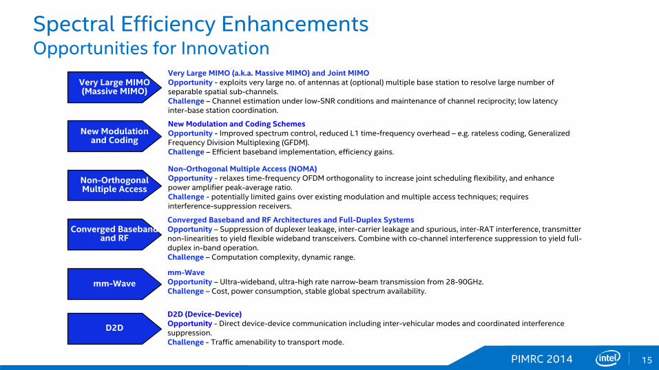
Very Large MIMO (a.k.a. Massive MIMO) and Joint MIMOOpportunity - exploits very large no. of antennas at (optional) multiple base station to resolve large number of separable spatial sub-channels.Challenge – Channel estimation under low-SNR conditions and maintenance of channel reciprocity; low latency inter-base station coordination.
New Modulation and Coding SchemesOpportunity - Improved spectrum control, reduced L1 time-frequency overhead – e.g. rateless coding, Generalized Frequency Division Multiplexing (GFDM).Challenge – Efficient baseband implementation, efficiency gains.
Non-Orthogonal Multiple Access (NOMA)Opportunity - relaxes time-frequency OFDM orthogonality to increase joint scheduling flexibility, and enhance power amplifier peak-average ratio.Challenge - potentially limited gains over existing modulation and multiple access techniques; requires interference-suppression receivers.
Converged Baseband and RF Architectures and Full-Duplex SystemsOpportunity – Suppression of duplexer leakage, inter-carrier leakage and spurious, inter-RAT interference, transmitter non-linearities to yield flexible wideband transceivers. Combine with co-channel interference suppression to yield full-duplex in-band operation.Challenge – Computation complexity, dynamic range.
mm-Wavemm-WaveOpportunity – Ultra-wideband, ultra-high rate narrow-beam transmission from 28-90GHz.Challenge – Cost, power consumption, stable global spectrum availability.
D2D
D2D (Device-Device)Opportunity - Direct device-device communication including inter-vehicular modes and coordinated interference suppression.Challenge - Traffic amenability to transport mode.

PIMRC 2014 16
mm-Wave System Design Historical Perspective
J. Gardiner, “Microwave and mm-WAVE Technology Requirements…European 4th-Framework…”,
Microwave Symp. Digest, 1995
1995
J.J. O'Reilly, et al, “MODAL: an Enabling Technology for Wireless Access”, 1993. 4th-IEE Conf. Telecomm.
1993
PIMRC 2014 17
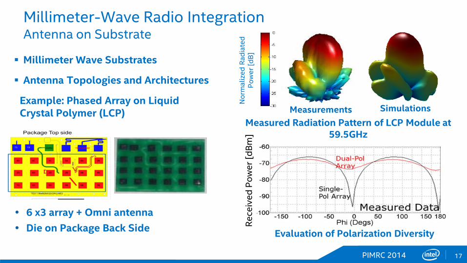
Millimeter-Wave Radio Integration Antenna on Substrate
Millimeter Wave Substrates
Antenna Topologies and Architectures
Nor
mal
ized
Rad
iate
d P
ower
[dB
]
Measured Radiation Pattern of LCP Module at 59.5GHz
Example: Phased Array on Liquid Crystal Polymer (LCP)
6 x3 array + Omni antenna Die on Package Back Side Re
ceiv
ed P
ower
[dBm
]
Measurements Simulations
Evaluation of Polarization Diversity

PIMRC 2014 18
Core Mobile Technology Evolution – Potential Future
5
10
15
20
25
2012 2014 2016 2018 2020
Estimated AP Node vs. Year (PQR)
AP Geometry (nm)
AP
Geo
met
ry (n
m)
Year
22nm
14nm 10nm
7nm
Source: Fudzilla
Q3 Q4Q2Q12013 2014 2015 2016 2017 2018 2019
Q3 Q4Q2Q1 Q3 Q4Q2Q1 Q3 Q4Q2Q1 Q3 Q4Q2Q1 Q3 Q4Q2Q1 Q3 Q4Q2Q1
Design Cycle #1
Design Cycle #2
Design Cycle #3
Design Cycle #4
7160 726040nm R10R9 28nm
Atom Z24xx
Cat-6Cat-4
32nm
1-Core 32-Bit
Atom Z25xx32nm
2-Core 32-Bit
2020SoFIA LTE4-Core 64-Bit
Atom Z37xx4-Core 64-Bit
22nm
28nm
0
200
400
600
800
1000
1200
2012 2014 2016 2018 2020
LTE Downlink Data Rate vs. Year
Downlink Data Rate (Mbps)
Dow
nlin
k D
ata
Rate
(Mbp
s)Year
7160(Cat-4)
7260(Cat-6)
1Gbps
Potential Design Region – Ultra Premium Devices
Example Design Cycle Iteration
Simple Linear Extrapolation
Design, Product and Process predictions are speculative and not to be relied upon. Design cycles and process nodes may be realized more or less quickly than noted.

PIMRC 2014 19
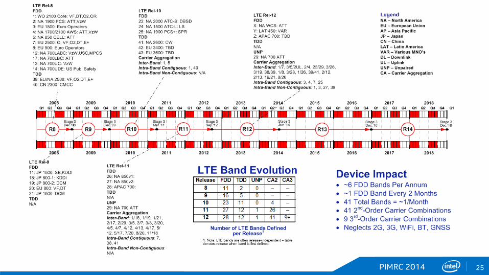
LTE Band Support Evolution Looking Ahead at Potential Futures
LTE Bandwidth Support • 7.5bps/Hz efficiency @ 2x2 • 1Gbps requires ~130MHz @ 2x2
~70MHz @ 4x4
0
20
40
60
80
100
2008 2010 2012 2014 2016 2018 2020
Band or Band Combination Support vs. Year
Ban
d or
Ban
d C
ombi
natio
n C
ount
Year
Defined Bands and BandCombinations
Defined Bands Supported Bands
Supported Bands andBand Combinations
LTE Band Support • Growth in defined bands may be slowing • Band combinations growing rapidly • Supporting the emerging set of aggregated
band combinations becoming complex
0
40
80
120
160
200
2012 2014 2016 2018 2020
Aggregated Bandwidth vs. Year
Aggregated Bandwidth (MHz)
Agg
rega
ted
Ban
dwid
th (M
Hz)
Year
20MHz
150MHz
100MHz
40MHz
Simple Linear Extrapolation1
Design, Product and Process predictions are speculative and not to be relied upon. Design cycles and process nodes may be realized more or less quickly than noted.

PIMRC 2014 20
ITU and 5G Requirements ITU-R M.[IMT.VISION]
Attribute IMT-Adv. 4G
IMT-Future 5G
Achievable Rates (Mbps) 1Gbps 10-50Gbps
Connection Density 106-107/km2
Mobility & Coverage 350km/h 500km/h
Energy Efficiency 1x 50-100x
Spectral Efficiency 1x 5-15x
Latency 10ms 1ms
Selected 5G Requirements (ITU WP5D – July 2014)

PIMRC 2014 21
4G Systems Remain Significant in a 5G World Low Cost Markets and Legacy Infrastructure
[1] “Self-Organizing Networks (SON): Self-Planning, Self-Optimization and Self-Healing for GSM, UMTS and LTE”, Hamied et. Al, 2012; [2] Strategy Analytics; [3] Ericsson and Cisco
0
2x10³
4x10³
6x10³
8x10³
1x10⁴
1.2x10⁴
2010 2015 2020 2025 2030 2035 2040
Mobile Subscribers by Air InterfaceProjection to 2040
GSMGSM - ProjectedWCDMA/HSPAWCDMA/HSPA - ProjectedLTELTE - ProjectedCDMACDMA - ProjectedXLTE - Projected
Subs
crip
tions
(Mill
ions
)
Year
LTE
WCDMA
GSM
CDMA
5GLTE Continues to Evolve
Speculative
PIMRC 2014 22
RF Proc
FEMWCDMA Rel-15
LTE Rel-15
WiFi – 802.11ax
WiGig – 802.11ad+
GSM/EDGE
“5G”
BT 5.x
GNSS
Location Core
CommsCore
Media Cores
PHY Processing
Sensors
ApplicationCores
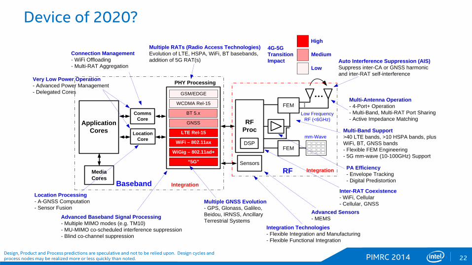
Auto Interference Suppression (AIS)Suppress inter-CA or GNSS harmonic and irter-RAT self-interference
Multiple RATs (Radio Access Technologies)Evolution of LTE, HSPA, WiFi, BT basebands, addition of 5G RAT(s)
Multiple GNSS Evolution - GPS, Glonass, Galileo, Beidou, IRNSS, Ancillary Terrestrial Systems
Multi-Band Support>40 LTE bands, >10 HSPA bands, plus WiFi, BT, GNSS bands- Flexible FEM Engineering- 5G mm-wave (10-100GHz) Support
Multi-Antenna Operation- 4-Port+ Operation- Multi-Band, Multi-RAT Port Sharing- Active Impedance Matching
Inter-RAT Coexistence- WiFi, Cellular- Cellular, GNSS
Advanced Baseband Signal Processing- Multiple MIMO modes (e.g. TM10)- MU-MIMO co-scheduled interference suppression- Blind co-channel suppression
Connection Management- WiFi Offloading- Multi-RAT Aggregation
PA Efficiency- Envelope Tracking- Digital Predistortion
Integration Technologies- Flexible Integration and Manufacturing- Flexible Functional Integration
Very Low Power Operation- Advanced Power Management- Delegated Cores
Location Processing- A-GNSS Computation- Sensor Fusion
Advanced Sensors- MEMS
Integration
4G-5GTransitionImpact
High
Medium
Low
IntegrationRFBaseband
Low FrequencyRF (<6GHz)
FEM
mm-WaveDSP
Device of 2020?
Design, Product and Process predictions are speculative and not to be relied upon. Design cycles and process nodes may be realized more or less quickly than noted.
PIMRC 2014 23 PIMRC 2014
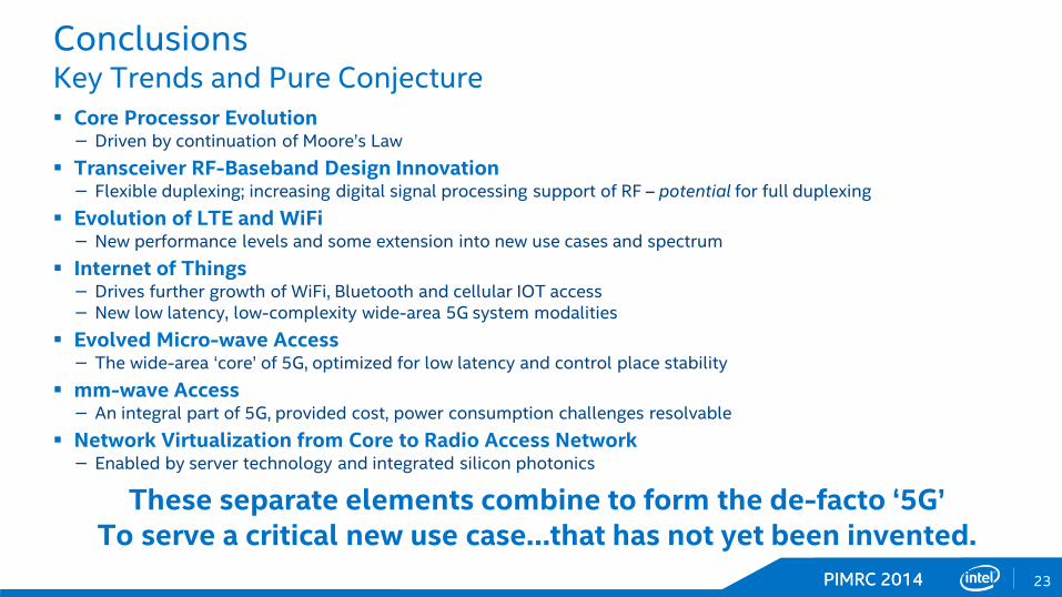
Conclusions Key Trends and Pure Conjecture Core Processor Evolution − Driven by continuation of Moore’s Law
Transceiver RF-Baseband Design Innovation − Flexible duplexing; increasing digital signal processing support of RF – potential for full duplexing
Evolution of LTE and WiFi − New performance levels and some extension into new use cases and spectrum
Internet of Things − Drives further growth of WiFi, Bluetooth and cellular IOT access − New low latency, low-complexity wide-area 5G system modalities
Evolved Micro-wave Access − The wide-area ‘core’ of 5G, optimized for low latency and control place stability
mm-wave Access − An integral part of 5G, provided cost, power consumption challenges resolvable
Network Virtualization from Core to Radio Access Network − Enabled by server technology and integrated silicon photonics
These separate elements combine to form the de-facto ‘5G’ To serve a critical new use case…that has not yet been invented.

Thank You
PIMRC 2014 25

PIMRC 2014 26
Moving Towards 5G Technology Timeline
Q3 Q4Q2Q12013 2014 2015 2016 2017 2018 2019 2020
Q3 Q4Q2Q1 Q3 Q4Q2Q1 Q3 Q4Q2Q1 Q3 Q4Q2Q1 Q3 Q4Q2Q1 Q3 Q4Q2Q1 Q3 Q4Q2Q1
ASN.1Dec.‘14
ASN.1Mar.‘16
ASN.11
Dec.‘173GPP
802.11ax TG StartMay ‘14
802.11ax
ASN.11
Sep.‘19
2013 2014 2015 2016 2017 2018 2019 2020
Draft 1.0Jul. ‘16
Draft 2.0Mar. ‘17
802.11ax Amendment1H-2019HEW2
Note 1: Strictly informal estimate of possible date.Note 2: High Efficiency WiFi.Note 3: Potential study and technical working group.
802.11ad+3 802.11ad+ Amendment1
WRC’15Nov. ‘15
WRC’182018
IMT-20202020
Rel-12 Rel-13 Rel-14 Rel-15 Rel-16
IMT-2020
Study1
IMT-2020? IMT-2020?
IMT-2020?
IMT-2020?

PIMRC 2014 27
Internet of Things (IOT) and Wearables Future Growth
PIMRC 2014 28
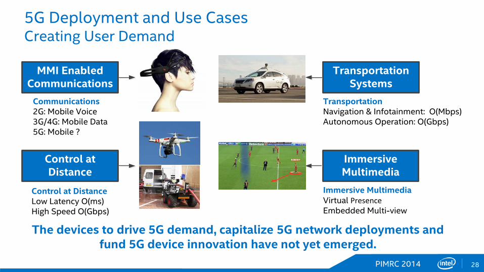
5G Deployment and Use Cases Creating User Demand
The devices to drive 5G demand, capitalize 5G network deployments and fund 5G device innovation have not yet emerged.
Control at Distance
ImmersiveMultimedia
Transportation Systems
MMI Enabled Communications
Communications2G: Mobile Voice3G/4G: Mobile Data5G: Mobile ?
Control at DistanceLow Latency O(ms)High Speed O(Gbps)
TransportationNavigation & Infotainment: O(Mbps)Autonomous Operation: O(Gbps)
Immersive MultimediaVirtual PresenceEmbedded Multi-view
PIMRC 2014 29
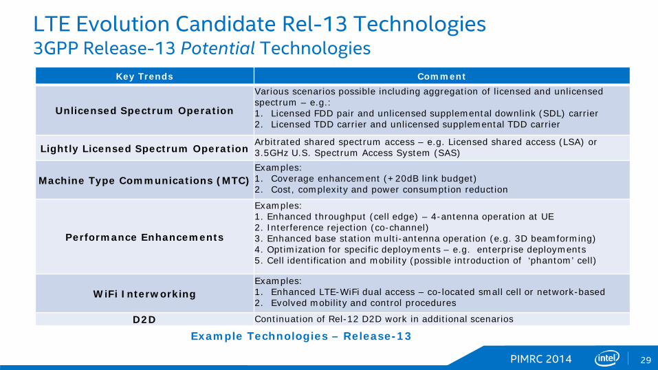
LTE Evolution Candidate Rel-13 Technologies 3GPP Release-13 Potential Technologies
Example Technologies – Release-13
Key Trends Comment
Unlicensed Spectrum Operation
Various scenarios possible including aggregation of licensed and unlicensed spectrum – e.g.: 1. Licensed FDD pair and unlicensed supplemental downlink (SDL) carrier 2. Licensed TDD carrier and unlicensed supplemental TDD carrier
Lightly Licensed Spectrum Operation Arbitrated shared spectrum access – e.g. Licensed shared access (LSA) or 3.5GHz U.S. Spectrum Access System (SAS)
Machine Type Communications (MTC) Examples: 1. Coverage enhancement (+20dB link budget) 2. Cost, complexity and power consumption reduction
Performance Enhancements
Examples: 1. Enhanced throughput (cell edge) – 4-antenna operation at UE 2. Interference rejection (co-channel) 3. Enhanced base station multi-antenna operation (e.g. 3D beamforming) 4. Optimization for specific deployments – e.g. enterprise deployments 5. Cell identification and mobility (possible introduction of ‘phantom’ cell)
WiFi Interworking Examples: 1. Enhanced LTE-WiFi dual access – co-located small cell or network-based 2. Evolved mobility and control procedures
D2D Continuation of Rel-12 D2D work in additional scenarios
PIMRC 2014 30
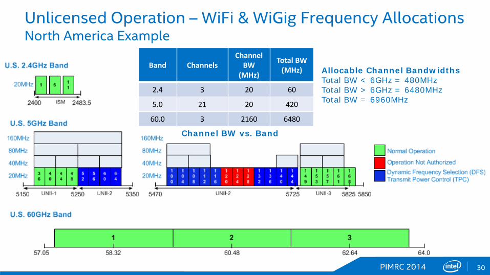
Unlicensed Operation – WiFi & WiGig Frequency Allocations North America Example
Band Channels Channel
BW (MHz)
Total BW (MHz)
2.4 3 20 60
5.0 21 20 420
60.0 3 2160 6480
Channel BW vs. Band
Allocable Channel Bandwidths Total BW < 6GHz = 480MHz Total BW > 6GHz = 6480MHz Total BW = 6960MHz
PIMRC 2014 31
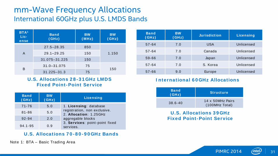
mm-Wave Frequency Allocations International 60GHz plus U.S. LMDS Bands
Band (GHz)
BW (GHz) Licensing
71-76 5.0 1. Licensing: database registration, non exclusive. 2. Allocation: 1.25GHz aggregable blocks 3. Services: point-point fixed services.
81-86 5.0
92-94 2.0
94.1-95 0.9
U.S. Allocations 70-80-90GHz Bands
BTA1 Lic- ense
Band (GHz)
BW (MHz)
BW (GHz)
A
27.5–28.35 850
1.150 29.1–29.25 150
31.075–31.225 150
B 31.0–31.075 75
150 31.225–31.3 75
Note 1: BTA – Basic Trading Area
U.S. Allocations 28-31GHz LMDS Fixed Point-Point Service
Band (GHz) Structure
38.6-40 14 x 50MHz Pairs (100MHz Total)
U.S. Allocations 39GHz Fixed Point-Point Service
Band (GHz)
BW (GHz) Jurisdiction Licensing
57-64 7.0 USA Unlicensed
57-64 7.0 Canada Unlicensed
59-66 7.0 Japan Unlicensed
57-64 7.0 S. Korea Unlicensed
57-66 9.0 Europe Unlicensed
International 60GHz Allocations

PIMRC 2014 32
Dense Enterprise Deployment Enterprise Coordinated Radio Access Network (C-RAN)
Remote Radio Heads
Remote Radio Heads
Metro-Ethernet Backhaul to Internet (S1 Interface)
Metro-Ethernet Backhaul to Internet (S1 Interface)
Server Coordinated Logical Cells
Server Coordinated Logical Cells
Single Mode Fiber+ Power Distribution
(~1300nm)
Single Mode Fiber+ Power Distribution
(~1300nm)
Routing and Power Distribution
Routing and Power Distribution
PIMRC 2014 33