piezoelectric energy harvesting with 3d-printed light...
TRANSCRIPT
Piezoelectric Energy Harvesting with 3D-Printed Light-Up Shoe
Natalie Chapman Brad Chavero [email protected] [email protected] Mathias Cross Diane Li Kelsey McLennan [email protected] [email protected] [email protected]
Ryan Gamadia* [email protected]
New Jersey Governor’s School of Engineering and Technology
21 July 2017
*Corresponding Author
Abstract— Piezoelectricity, electricity generated from mechanical stress [1], is of interest as a potential source of alternative energy. Historically, piezoelectric materials have been used on a small scale for precise applications, such as sound detection and motors. The goal of this project was to expand the possibilities of piezoelectricity by attempting to harvest the energy generated from pressure while walking and use that energy to light up LEDs on a 3D-printed sneaker. One of the barriers of collecting usable piezoelectricity was that many piezoelectric materials generate very low current. To overcome this issue, various circuit designs were tested; it was determined that power output could be maximized by wiring the piezoelectric elements individually to bridge rectifiers before wiring the bridge rectifiers in parallel. Then, the current traveled to a charging circuit for rechargeable batteries and the batteries supplied power to the LEDs. In the final product, the flexibility of the material selected for the shoe sole seemed to reduce the efficiency of the piezoelectric elements and remains as an area for further research.
I. INTRODUCTION Due to rapid population and industrial growth,
non-renewable resources are being depleted at an alarming pace. With coal, oil, and gas projected to run out in 35 to 42 years, alternative renewable energies are increasingly researched and implemented in global society [2]. Through the use of piezoelectricity, everyday tasks such as driving and walking could be transformed into energy harvesting actions as the pressure from car wheels and feet could provide energy for the world to use. With billions of people partaking in
piezoelectric energy harvesting, the need for other forms of energy, renewable and nonrenewable, would decrease with minimal cost to the environment or changes to society or individual daily life. Designing a 3D-printed light-up shoe serves as one of the first steps in researching piezoelectricity as a viable alternative energy source.
II. OVERVIEW OF COMPONENTS IN THE SHOE
A. Generating Piezoelectricity Jacques and Pierre Curie first observed the effect of
piezoelectric materials in 1880 [3]. These materials contain Weiss domains, locally polarized regions with uniform magnetic moments. Since the Weiss domains are arranged randomly, the material as a whole has a net charge of zero in its undisturbed state. Application of mechanical stress causes the Weiss domains to realign and creates a net positive charge on one side of the material and a net negative charge on the other [4]. Thus, mechanical stress generates a difference in electrical potential that induces the flow of current.
Piezoelectric materials act as transducers, converting physical signals into electrical ones when inserted between two electrodes in a piezoelectric pad or element. The piezoelectric pads used in the shoe are circular in shape, with a 27 mm outer brass diameter and are generally used with acoustic guitars, drums, or contact microphones [5]. These piezoelectric pads are made from lead zirconate titanate (PZT) [6]. In the PZT unit
1

cell, a single titanium or zirconium ion interacts with 6 surrounding oxygen atoms as shown in Figure 1. The central ions are tetravalent, meaning that they are surrounded by four free electrons. When the crystal structure is deformed, the titanium or zirconium atom in the center is no longer in its lowest potential energy, destabilizing the material. This instability makes the central atom susceptible to shifting around within the unit cell. As the positive central ion moves up or down, the side of the molecule to which it moves becomes more positive while the other side becomes negative, forming a dipole. At the microscale level, this manifests as the realignment of Weiss domains explained above.
Fig. 1 Arrangement of atoms in the PZT unit cell [7]
B. Alternating Current and Direct Current The current generated from the piezoelectric pads is
alternating current (AC), since it changes direction each time a pad is pressed. However, the current used for recharging the batteries and lighting LEDs must be direct current (DC), meaning current direction and voltage polarity must stay constant [8]. Direct current is necessary for storing energy in rechargeable power cells in order to differentiate the direction of current flow during charging from that during discharging.
C. Potential Components for Modifying Energy from Piezo Elements into Harvestable Energy
1) Bridge Rectifiers: A bridge rectifier is an electrical component made up of four diodes. A diode only permits the flow of current in a single direction. The diodes are arranged so that alternating current entering the bridge rectifier is redirected to exit positive and negative terminals as direct current [9].
2) Transistors: A transistor is an electrical component that can amplify current or act as a switch within a circuit.
Transistors usually have three main semiconductive terminals, and the main types of transistors are bipolar junction transistors (BJT) and field effect transistors (FET) [10]. BJTs are current-controlled with collector, base, and emitter terminals. Semiconductor types in BJTs may be ordered as NPN or PNP, which transfer current by electron flow or hole flow respectively. Applying a control current through the base of a BJT allows a stronger current to flow between the collector and emitter. Larger base currents cause proportional increases in current through the collector and emitter. In certain applications, this feature of the BJT is disadvantageous because it disrupts the power sources in the circuit.
Field effect transistors are voltage-controlled and consist of a gate, a source, and a drain. Similarly to BJTs, FETs act as switches, closing an open circuit between the source and the drain when voltage passes through the gate. However, FETs have a high resistance and lower the current output of the circuit. This protects sensitive electronic components along the circuit and prevents loading within the circuit, but it does not have the ability to amplify current like a BJT [11]. Since piezoelectric materials tend to produce high voltage but low current, they have been used to provide control voltage to FETs so that the two may be used in conjunction as a switch to a larger power source. Since the project focused on the harvesting of piezoelectricity, transistors were not considered for the circuit as they would not store the generated piezoelectricity but rather amplify the current.
3) Voltage Regulators: Voltage regulators generate a constant voltage output from a variable input to protect sensitive electronics. The two main types of voltage regulators are linear voltage regulators and switching voltage regulators [12]. Linear voltage regulators use a power transistor and voltage divider network to regulate voltage. The voltage divider network provides feedback to the power transistor which helps the transistor to accurately correct the varying input voltage to a constant output voltage. However, linear voltage regulators are inefficient due to the fact that they convert part of the current into heat. Switching voltage regulators differ from linear voltage regulators in that they control voltage output by storing energy at a defined level and then use feedback to maintain that voltage. Using a transistor, a switching voltage regulator can boost the power of the circuit if the power falls below the set storage level. This system allows them to be more efficient than their linear counterparts because the transistor is able to adjust the switching voltage regulator from low to high resistance more easily [13]. However, a voltage regulator was not included in the shoe circuit due to the fact that the voltage produced from the piezoelectric pads never reached the threshold required for a voltage regulator to be needed as part of the circuit.
2
4) Capacitors: A capacitor consists of an insulating material capped with two conducting electrodes on either side. Since charge builds up in a capacitor, it can serve as temporary energy storage and help smooth an oscillating voltage. The degree to which a capacitor stores current is determined by the structure and material of the component.
D. Recharging a Battery In a rechargeable lithium-ion battery, there are layers of
lithium compound. Ions are added between layers of the compound, and the movement of these ions produces charge. Lithium ions move from the cathode to the anode while charging and from the anode to the cathode of the battery while discharging. Lithium batteries are capable of storing large amounts of energy in small spaces, and do not discharge even if the battery is not in use [14].
Charging circuits are used to regulate the voltage and current supplied to rechargeable batteries. If a battery is overcharged, it can overheat and explode. If a battery discharges too much energy, its charging capacity can be permanently lowered [15]. A charging circuit can regulate the amount of charge in a battery and prevent either extreme from damaging the battery.
E. CAD and 3D Printing Computer-Aided Design allows parts, assemblies, and
drawings to be virtually created. For this project, the CAD software Solidworks was used. Furthermore, CAD parts and assemblies can be converted into tangible 3D parts/models. After testing the prototype, CAD allows the design to be modified, revised, and improved in the virtual space to be built and tested again. This allows a design to be optimized for performance while expending minimal materials.
The 3D printing process is an additive material process wherein a spool of specified material is melted and extruded onto a plate by a Cartesian robot within a defined space known as a work envelope. This method of rapid prototyping allows for the same CAD part to be printed multiple times using different materials. The ability for mass production and material testing are useful for research, design optimization, and manufacturing. Moreover, CAD allows the shoe to be personalized to any consumer’s fit and needs by virtually modifying the design. This circumvents material costs of physically modelling a design first then wasting materials to modify it.
F. 3D Printing Filaments 1) Polylactic Acid (PLA): PLA is one of the most commonly
used filaments because it is easy to print and biodegradable. PLA is stiff and brittle, so it is not ideal for shoes.
2) Acrylonitrile Butadiene Styrene (ABS): ABS is a durable, heat-resistant, and water-resistant material. It is a stiffer filament than PLA, but more flexible after printing. Additionally, ABS tends to warp while cooling, which can cause problems with the structural design.
3) Chlorinated Polyethylene (CPE): CPE is stronger than PLA and does not warp like ABS. It is durable, flexible, impact-resistant, and heat-resistant but not water-resistant.
4) Nylon: Nylon has high strength and high heat resistance. It is incredibly durable and very versatile but also not water-resistant. Nylon is used for living hinges and functional parts.
5) Polyvinyl Alcohol (PVA): PVA is a stiff, water-soluble 3D printing filament. [16]
6) Thermoplastic Elastomer (TPE): TPE is a more flexible filament that acts more like rubber. Parts made from TPE are impact-resistant, making it a very strong candidate for a printed shoe.
7) Thermoplastic Polyurethane (TPU): TPU is a rubbery, impact-resistant, and water-resistant material, making it another viable candidate for a shoe.
III. DESIGN PROCESS
A. 3D Design of Shoe
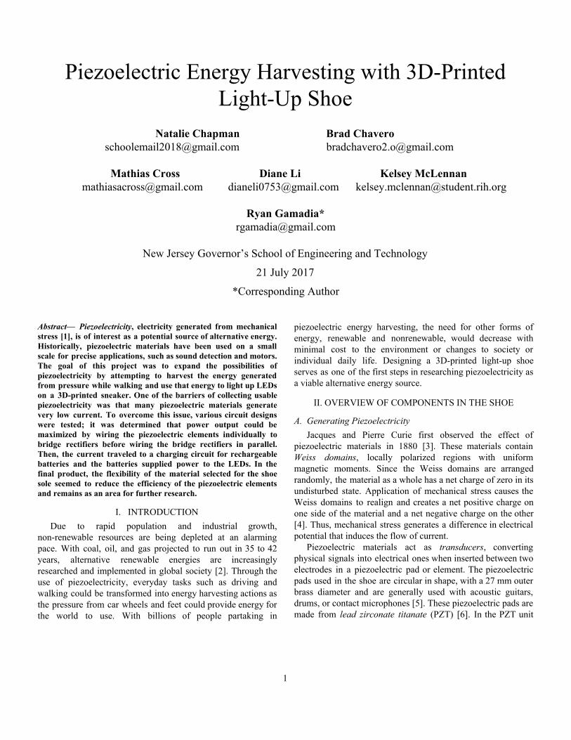
Fig. 2 SolidWorks design of a shoe with detachable soles [17]
The shoe was designed using Solidworks CAD software.
Separate shoe and sole parts were virtually assembled as seen in Figure 2. The sole part of the model was modified to a simpler design so that it could be 3D printed more easily. The modified design is shown in Figure 3 without the ridges on the bottom. The 3D printer used was a Lulzbot Mini with a 6” x 6” x 6” work envelope. Due to the small size of the printer, the shoe and sole parts were each split into two halves, then scaled down to 90% of their original size using Cura, a slicer software that converts CAD models into individual layers in preparation for 3D printing [18].
3
The Lulzbot Mini printed the designs by heating up the nozzle to extrude the filament and heating up the plate to provide stability for certain materials during the printing process. The 3D printer built the parts layer by layer with a 10% fill density. All the printing took an approximate total of 32 hours. The shoe parts were 3D printed in PLA as a prototype since the filament was readily available and easier to print. Meanwhile, the sole parts were 3D printed in the NinjaFlex brand of TPU to test the performance of the piezoelectric pads on a flexible base similar to one that might exist in a marketable product. Each part’s halves were hot glued together to complete the part.
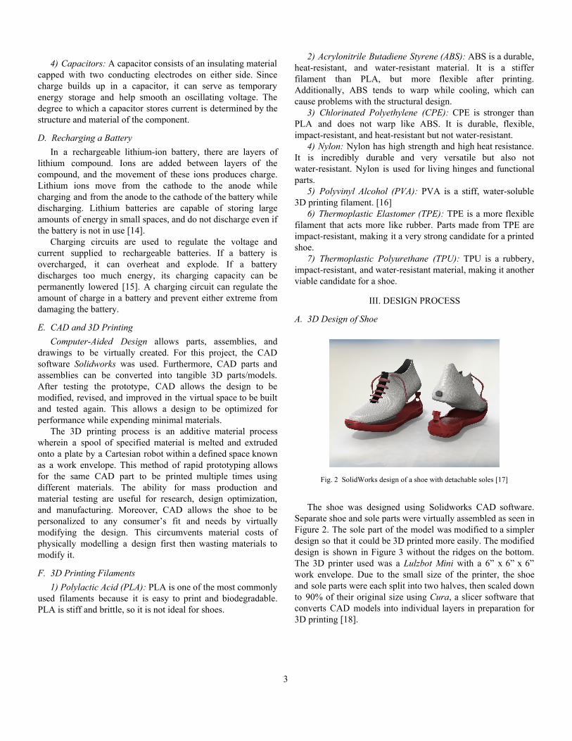
Fig. 3 Simplified design of the sole
Fig. 4 SolidWorks model of split shoe
The circuit compartment, in Figure 5, was also created
using Solidworks. It was created to safely house circuit parts, such as the Gikfun Pro Mini, a circuit board that controlled the lighting patterns of the LEDs. The circuit compartment was designed with space for 3 separate components: bridge rectifiers (6), the rechargeable batteries (2), and the Gikfun Pro Mini, pictured from left to right. This was printed in PLA with 10% fill density by a Lulzbot Mini for 13 hours. Then, the container was hot glued to the back of the shoe part.
Fig. 5 CAD drawings of the circuitry compartment
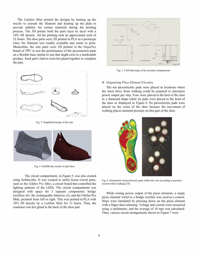
B. Organizing Piezo Element Circuitry The ten piezoelectric pads were placed in locations where
the most force from walking could be acquired to maximize power output per step. Four were placed in the heel of the shoe in a diamond shape while six pads were placed in the front of the shoe as displayed in Figure 6. No piezoelectric pads were placed on the waist of the shoe because the movement of walking places minimal pressure on this part of the shoe.
Fig. 6 Orientation of piezoelectric pads within the sole according to pressure exerted while walking [19]
While testing power output of the piezo elements, a single
piezo element wired to a bridge rectifier was used as a control. Steps were simulated by pressing down on the piezo element with a finger then releasing. Voltage and current were measured using a multimeter, and the average of 10 taps was calculated. Then, various circuit arrangements shown in Figure 7 were
4

Fig. 7 Different arrangements of piezoelectric circuitry
configured using four piezo pads and tested similarly in order to find the one that might maximize the power produced, particularly with respect to current. Circuit 5 was determined to be most efficient.
In the final design, each of the ten piezoelectric pads was wired to its own bridge rectifier. The bridge rectifiers were wired in parallel with all positive terminals connected to each other and all negative terminals connected to each other.
Fig. 8 Piezoelectric pad circuit within sole of shoe
C. Linking Piezoelectric Pads to LEDs Through Rechargeable Batteries
Due to the low power produced from the piezoelectric pads per step, the shoe required an energy storage system to provide enough power to reliably turn on all LEDs for an extended period. Two 3.7 V rechargeable Li-ion batteries were chosen as the energy storage system within the circuit. A double-pole double-throw (DPDT) switch, a 6-pin toggle switch, was used to switch from charging the batteries with the piezoelectric pads to discharging the batteries to the LED lights. Wiring the batteries in series versus parallel were both considered while optimizing circuitry.
To charge the batteries, the voltage of the power source had to be greater than that of the batteries. Wiring the batteries in series would require a power source with at least 7.4 V, the added voltage of both batteries; otherwise, the batteries would not charge. To prevent this, wiring in parallel would only require a 3.7 V power source for charging the batteries. In contrast, the 2 batteries had to be in series to power the Gikfun Pro Mini and the LEDs because they needed the combined
voltage of 7.4 V. Therefore, the optimal charging circuit would be in parallel but the discharging circuit would need to be in series.
However, testing the final circuit of ten piezo elements revealed that the voltage was sustainably high at an average of 20.3 V while the current was low. This meant that the voltage from the piezo elements would be enough to be split between the batteries in a series circuit during charging while preserving a constant current. The combined voltage of the batteries would also be available during discharge of the batteries into the LED circuit.
D. Gikfun Pro Mini and Modified C Code
Fig. 9 Gikfun and LED circuitry
The Gikfun Pro Mini was wired according to Figure 9. Code
was written in the Arduino IDE program using a modified version of C and uploaded via a USB to serial adapter. The code set up pins 2-17 inclusive as output pins and initialized all to LOW. LOW signified that the pin was at 0.0 V and acted as a sink for current. Positive wires were attached to pins 2-9; negative wires were attached to pins 10-17. In the looped
5
function, pins 2-9 were set to HIGH sequentially, generating a voltage of 3.3 V. Each time a pin was set to HIGH, current flowed through the LED strip to the corresponding LOW pin. The final result caused the LEDs to light up in a circular pattern along the rim of the shoe.
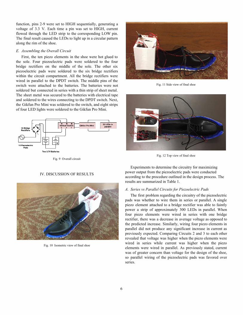
E. Assembling the Overall Circuit First, the ten piezo elements in the shoe were hot glued to
the sole. Four piezoelectric pads were soldered to the four bridge rectifiers on the middle of the sole. The other six piezoelectric pads were soldered to the six bridge rectifiers within the circuit compartment. All the bridge rectifiers were wired in parallel to the DPDT switch. The middle pins of the switch were attached to the batteries. The batteries were not soldered but connected in series with a thin strip of sheet metal. The sheet metal was secured to the batteries with electrical tape and soldered to the wires connecting to the DPDT switch. Next, the Gikfun Pro Mini was soldered to the switch, and eight strips of four LED lights were soldered to the Gikfun Pro Mini.
Fig. 9 Overall circuit
IV. DISCUSSION OF RESULTS
Fig. 10 Isometric view of final shoe
Fig. 11 Side view of final shoe
Fig. 12 Top view of final shoe
Experiments to determine the circuitry for maximizing
power output from the piezoelectric pads were conducted according to the procedure outlined in the design process. The results are summarized in Table 1.
A. Series vs Parallel Circuits for Piezoelectric Pads The first problem regarding the circuitry of the piezoelectric
pads was whether to wire them in series or parallel. A single piezo element attached to a bridge rectifier was able to faintly power a strip of approximately 300 LEDs in parallel. When four piezo elements were wired in series with one bridge rectifier, there was a decrease in average voltage as opposed to the predicted increase. Similarly, wiring four piezo elements in parallel did not produce any significant increase in current as previously expected. Comparing Circuits 2 and 3 to each other revealed that voltage was higher when the piezo elements were wired in series while current was higher when the piezo elements were wired in parallel. As previously stated, current was of greater concern than voltage for the design of the shoe, so parallel wiring of the piezoelectric pads was favored over series.
6

TABLE 1
Aᴠᴇʀᴀɢᴇ Pᴏᴡᴇʀ Oᴜᴛᴘᴜᴛ ʀᴏᴍ Dɪ ᴇʀᴇɴᴛ Aʀʀᴀɴɢᴇᴍᴇɴᴛ ᴏ Pɪᴇᴢᴏᴇʟᴇᴄᴛʀɪᴄ Cɪʀᴄᴜɪᴛʀʏ
Circuit #
# of Piezo Elements
Circuit Organization Average Voltage (V)
Average Current (µA)
Lights Up Strip of LEDs (~300)
1 1 piezo attached to bridge rectifier (b.r.) 4.46 5.65 Yes- faintly
2 4 4 piezo in series with one b.r. 3.34 2.79 No
3 4 4 piezo in parallel with one b.r. 2.11 5.74 Yes- barely at all
4 4 4 piezo attached to 4 b.r. in series 5.72 8.10 Yes- very faintly
5 4 4 piezo attached to 4 b.r. in parallel 7.70 21.27 Yes
6 4 4 piezo attached to 4 b.r. in series in 2 stacks of 2 w/ folded paper in between
2.90 6.44 Yes- very faintly
7 4 4 piezo attached to 4 b.r. in parallel in 2 stacks of 2 w/ folded paper in between
8.24 11.97 Yes (inconsistent)
8 10 10 piezo pads wired to 10 b.r. in parallel and attached to the final sole
20.3 ** No
**Ammeter component of the multimeter was broken
B. Effect of Bridge Rectifiers on the Piezoelectric Circuit Wiring each piezo element to its own bridge rectifier before
wiring the bridge rectifiers in series caused minor increases in both voltage and current. Having four piezo elements attached to four bridge rectifiers in parallel produced the most noticeable improvements in voltage and current. Voltage increased from an average of 4.46 V in control Circuit 1 to 7.70 V in Circuit 5; current increased from an average of 5.65 µA in the control Circuit 1 to 21.27 µA in experimental Circuit 5.
These results influenced the amount of bridge rectifiers that were placed in the sole of the shoe and also redefined the maximum power that could be produced from the piezoelectric shoes themselves. It was theorized that without the bridge rectifiers, the current was much lower because the positive and negative AC from each piezoelectric pad collided and had a destructive interaction, lowering the total current produced. By converting the AC to DC, the current was greatly amplified as all DC was positive, allowing the current to build. In contrast, placing multiple piezo pads in series would generate less power than a single piezo pad due to the conflicting currents.
Thus, Circuit 5 was selected as the circuit design for the final shoe. With all circuits, there was significant variation in voltage and current produced with each simulated step, shown in Figure 13.
Fig. 13 Current and voltage from simulated steps
B. Single Layer of Piezoelectric Pads vs Stacking Another idea to maximize the piezoelectric power of the
shoe was to stack piezoelectric pads upon each other in order to generate more electricity [20]. However, after testing this hypothesis, it was found that stacking the pads had no voltage increase. In Table 1, it can be observed that stacking the pads lowered average values of the output voltage compared to
7

single layered piezoelectric pads. A piece of folded paper was placed between the two pads in each stack because the bulge of solder on the pads prevented them from being stacked directly. The lack of increase in power output was thought to be explained by a decrease in deformation of individual pads when multiple were stacked since a certain amount of pressure was absorbed by the paper as well.
C. Determining the Effect of Batteries vs Capacitors Both batteries and capacitors store energy. Batteries store
energy for prolonged periods of time while capacitors only briefly store energy and have a smoothing effect on current. This is useful for sending current into a source that requires stable current flow. However, the addition of a capacitor to Circuit 5 lowered the overall voltage produced by the piezoelectric pads. The difference in voltage can be seen when comparing Figures 14 and 15. A capacitor was not used in the final circuit because it was not an effective use of the limited space in the shoe and diminished piezoelectric output.
Fig. 14 An oscilloscope reading of four piezoelectric pads wired to four bridge rectifiers in parallel
Fig. 15 An oscilloscope reading of four piezoelectric pads wired to four bridge rectifiers in parallel with the addition of a capacitor
D. 3D Printing Complications Due to inconsistencies in scaling, the final shoe part was
printed to be 1 inch smaller than the sole part. The Lulzbot Mini also experienced difficulties when 3D printing with TPU. The filament did not fuse properly, producing the stranded appearance seen in Figure 16.
Fig. 16 Stranded bottom face of the sole part
E. Power Output of Circuit When Attached to Sole As seen in Table 1, when the piezoelectric pad circuit was
attached to the sole, it was not able to light up a strip of LEDs despite the higher voltage produced by ten piezo elements. The current could not be measured because the ammeter was broken, but comparison with the only other circuit that failed to light the strip of LEDs suggested that the result was caused by very low current. Keeping in mind the effect of stacking piezo elements with layers of folded paper in between on power output, it was theorized that this lower current was due to the flexible TPU material of the sole compressing instead of the more rigid piezoelectric pads on top of the sole.
Additionally, taking actual steps on the sole instead of the steps simulated by pressing individual piezoelectric pads with fingers was much less effective. Since the pressure applied was less focused, the voltage generated never increased past 1.0 V except when jumping up and down on the sole. It is unknown whether or not the power of the piezoelectric pads was enough to charge the batteries because there was not a means of measuring the level of charge in the battery.
V. CONCLUSIONS
A. Findings Wiring piezoelectric elements in series before converting
AC to DC caused some degree of cancellation of current and voltage as opposite polarities ran into one another. This was remedied by performing the AC to DC conversion prior to combining the current generated from individual elements. One
8

of the drawbacks of piezoelectric materials was that the current produced was highly variable, particularly because of the pressure generated from footsteps. Yet the addition of a smoothing capacitor into the circuit limited power production significantly. The material used as the base upon which pressure was applied also had a significant impact on power generation. If the sole of the shoe is too easily compressible then there is a risk that the pressure applied will cause compression of the sole itself instead of the piezoelectric material. The material of the shoe part itself was rigid and could not fit on a foot in addition to discrepancies between the size of the sole and shoe parts. Furthermore, the circuitry was not protected from environmental damage. Thus, the final shoe produced can only be considered a prototype.
B. Future Improvements Another option for the piezoelectric material would be to
create an entire layer of the material instead of using individual pads. This layer would most likely be made out of PZT epoxy rather than PZT since PZT itself is too brittle. The structure of the shoe may be improved by modifying the circuit compartment to be smaller, making the shoe more fashionable and marketable. Further research into 3D printing filament selection would also raise the performance of the shoe. In particular, the sole should be printed in a less flexible filament and the shoe should be printed in a more flexible filament. Dual filament printing of PLA and TPU could provide the solution for a final product of intermediate flexibility. Additionally, replacing the copper wires with a conductive thread would increase compactness of the circuitry as the thread is thinner and more flexible than wires. Investing in research towards the inclusion of a transistor or voltage regulator could also improve the shoe circuitry by amplifying current or stabilizing voltage respectively. The circuit is currently powered by two batteries that charge and discharge, but further research into capacitors could lead to future versions of the circuit where a capacitor replaces the batteries’ role as power storage. In order to conduct this research, more powerful tools and software would need to be used to measure patterns of current and voltage at different points along the circuit.
C. Potential Applications for Piezoelectricity Piezoelectricity has many future applications to help power
the globe more effectively and cleanly. Piezoelectricity could be used in everyday objects, such shoes or car tires. Besides lighting LEDs, the piezoelectric shoe could also be used to power mobile devices during transit. With every rotation of a tire with piezoelectric elements, immense amounts of power could be generated. Piezoelectricity could also help power cities and urban areas with piezoelectric sidewalks and walkways helping to power streetlights, public buildings, and
community spaces. Integrating piezoelectric material into stationary surfaces instead of moving objects would likely produce better results since the material would be strained less and require less maintenance.
ACKNOWLEDGEMENTS The authors of this paper would like to thank Ryan
Gamadia, the mentor for this project and Dr. Kimberly Cook-Chennault, the creator of this project. The authors would also like to thank Nick Faenza, Dr. Kim Scott, Anthony Yang, Jaimie Swartz, Steve Orbine, Zichen Lao, Karan Mahesh, Jillian Maling, and Einar Magnusson for their insightful advice and guidance whenever help was needed. The authors of this paper would also like to thank Dean Ilene Rosen, NJ Governor's School of Engineering & Technology Director, Dean Jean Patrick Antoine, NJ Governor's School of Engineering & Technology Associate Director, Rutgers University, Rutgers School of Engineering, Lockheed Martin, and Silverline Windows for their support of The New Jersey Governor's School of Engineering and Technology.
REFERENCES [1] “The Piezoelectric Effect - Piezoelectric Motors & Motion Systems,”
Nanomotion. [Online]. Available: http://www.nanomotion.com/piezo-ceramic-motor-technology/piezoelectric-effect/. [Accessed: 15-Jul-2017].
[2] A. Schwartz, “Visualizing All The Non-Renewable Resources We Have Left,” Fast Company, 13-Nov-2014. [Online]. Available: https://www.fastcompany.com/1680136/visualizing-all-the-non-renewable-resources-we-have-left. [Accessed: 14-Jul-2017].
[3] “Piezoelectric Ceramics Properties & Applications Chapter 2: Physical Basis.” Morgan Advanced Materials.
[4] “Piezotechnology: Fundamentals of Piezoelectricity,” Piezo Mechanics Design Tutorial: Fundamentals of Piezotechnology, Piezo Tutorial. [Online]. Available: http://www.piezo.ws/piezoelectric_actuator_tutorial/Piezo_Design_part2.php. [Accessed: 14-Jul-2017].
[5] “15 Pieces - 27mm Piezo Disc Elements with 4" Leads - Acoustic Pickup Cigar Box Guitar CBG: Everything Else,” Amazon.com: 15 Pieces - 27mm Piezo Disc Elements with 4" Leads - Acoustic Pickup Cigar Box Guitar CBG: Everything Else. [Online]. Available: https://www.amazon.com/15-Pieces-Elements-Acoustic-Pickup/dp/B00DH2QJG2/ref=sr_1_1?ie=UTF8&qid=1463964421&sr=8-1&keywords=piezo%2Belement. [Accessed: 14-Jul-2017].
[6] “What is PZT?,” What is PZT? | PZT Ceramic | PZT Theory and Use Information. [Online]. Available: https://www.americanpiezo.com/piezo-theory/pzt.html. [Accessed: 14-Jul-2017].
[7] “Lead-free Piezoelectric Ceramics.” [Online]. Available:http://www.ytca.com/lead_free_piezoelectric_ceramics. [Accessed: 15-Jul-2017].
[8] M. Brain, W. Harris, and R. Lamb, “How Electricity Works,” HowStuffWorks Science, 28-May-2004. [Online]. Available: http://science.howstuffworks.com/electricity8.htm. [Accessed: 14-Jul-2017].
[9] F. Electronics, “What is a Bridge Rectifier?,” What is a bridge rectifier, half wave rectifiers, semiconductor diodes, diode - Future Electronics.
9

[Online]. Available: http://www.futureelectronics.com/en/diodes/bridge-rectifiers.aspx. [Accessed: 15-Jul-2017].
[10] A., “Types of Transistors - Junction Transistors and FETs,” Electronics Hub, 06-Jun-2015. [Online]. Available: http://www.electronicshub.org/transistors-classification-and-types/. [Accessed: 15-Jul-2017].
[11] “Types of Transistors,” Learning About Electronics. [Online]. Available: http://www.learningaboutelectronics.com/Articles/Types-of-transistors.php. [Accessed: 15-Jul-2017].
[12] “Understanding How a Voltage Regulator Works,” Understanding How a Voltage Regulator Works | Analog Devices. [Online]. Available: http://www.analog.com/en/technical-articles/how-voltage-regulator-works.html. [Accessed: 15-Jul-2017].
[13] M. Burris, “Learn More About Three Different Types of Voltage Regulators,” Lifewire, 21-Mar-2017. [Online]. Available: https://www.lifewire.com/types-of-voltage-regulators-818851. [Accessed: 15-Jul-2017].
[14] “Is Lithium-ion the Ideal Battery?,” Basic to Advanced Battery Information from Battery University. [Online]. Available: http://batteryuniversity.com/learn/archive/is_lithium_ion_the_ideal_battery. [Accessed: 15-Jul-2017].
[15] D.-K. N. A. E., “A Designer's Guide to Lithium (Li-ion) Battery Charging,” A Designer's Guide to Lithium (Li-ion) Battery Charging | DigiKey. [Online]. Available: https://www.digikey.com/en/articles/techzone/2016/sep/a-designer-guide-fast-lithium-ion-battery-charging. [Accessed: 15-Jul-2017].
[16] “3D Printer Filament Comparison,” MatterHackers. [Online]. Available: https://www.matterhackers.com/3d-printer-filament-compare. [Accessed: 15-Jul-2017].
[17] A. Edgar, “Running Shoe with Interchangeable Soles,” GrabCAD - CAD library. [Online]. Available: https://grabcad.com/library/running-shoe-with-interchangeable-soles-1. [Accessed: 15-Jul-2017].
[18] A. Locker, “16 Best 3D Slicer Software Tools for 3D Printers (Most are Free),” All3DP, 18-Apr-2017. [Online]. Available: https://all3dp.com/1/best-3d-slicer-software-3d-printer/#what. [Accessed: 15-Jul-2017].
[19] A. Ahmedabad, “Posts about rehabilitation on The Sneaker Project,” The Sneaker Project, 24-Mar-2012. [Online]. Available: https://thesneakerguide.wordpress.com/tag/rehabilitaion/. [Accessed: 15-Jul-2017].
[20] J. Zhao and Z. You, “A Shoe-Embedded Piezoelectric Energy Harvester for Wearable Sensors,” Sensors, vol. 14, no. 7, pp. 12497–12510, 2014.
10