design methodology of piezoelectric energy-harvesting...
TRANSCRIPT
Noname manuscript No.(will be inserted by the editor)
Design methodology of piezoelectric energy-harvestingskin using topology optimization
A. Takezawa · M. Kitamura · S. L. Vatanabe · E. C. N. Silva
Received: date / Accepted: date
Abstract This paper describes a design methodologyfor piezoelectric energy harvesters that thinly encapsu-late the mechanical devices and exploit resonances from
higher-order vibrational modes. The direction of polar-ization determines the sign of the piezoelectric tensor toavoid cancellations of electric fields from opposite po-
larizations in the same circuit. The resultant modifiedequations of state are solved by finite element method(FEM). Combining this method with the solid isotropic
material with penalization (SIMP) method for piezo-electric material, we have developed an optimizationmethodology that optimizes the piezoelectric material
layout and polarization direction. Updating the densityfunction of the SIMP method is performed based onsensitivity analysis, the sequential linear programming
on the early stage of the optimization, and the phasefield method on the latter stage of the optimization toobtain clear optimal shapes without intermediate den-
sity. Numerical examples are provided that illustratethe validity and utility of the proposed method.
A. Takezawa · M. KitamuraDivision of Mechanical Systems and Applied MechanicsInstitute of Engineering, Hiroshima University,1-4-1 Kagamiyama, Higashi-hiroshima, Hiroshima 739-8527,JapanTel.: +81-82-424-7544Fax: +81-82-422-7194E-mail: [email protected]: [email protected]
S. L. Vatanabe and E. C. N. SilvaDepartment of Mechatronics and MechanicalSystems Engineering,Escola Politecnica da Universidade de Sao Paulo,Av. Prof. Mello Moraes, 2231, Sao Paulo,SP 05508-900, BrazilE-mail: [email protected]: [email protected]
1 Introduction
Vibration-based energy-harvesting technologies have atremendous amount of potential in various engineering
fields. The devices derive electrical energies by scaveng-ing from waste mechanical vibration energies. Such de-vices are expected to provide maintenance-free power
sourcing for small electrical devices such as wirelesssensors. This kind of technology can lead to new sys-tems for monitoring structural health or implementing
electrical medical devices. Vibration-based energy har-vesting can be achieved by three different mechanisms:electromagnetic, electrostatic and piezoelectric. Among
these, piezoelectric research is the more active field overthe past decade. Summaries of the related research andapplications can be found in several review articles (So-
dano et al., 2004; Beeby et al., 2006; Priya, 2007; Antonand Sodano, 2007; Cook-Chennault et al., 2008).
The piezoelectric energy harvester is constructedusually of a piezoelectric material with additional masses
located on a base structure. If a vibration has the samefrequency as an eigen-frequency of the device, the de-vice resonates and the piezoelectric material becomes
highly deformed. Dynamic mechanical stress developsand a polarization occurs in the piezoelectric material.A dynamic electric field and an accompanying electric
potential produces an output voltage across attachedelectrodes of the device. Several types of base struc-tures have been proposed, such as cantilevers, cylin-
ders, and clamped curved plates. The operation of thedevice exploits its fundamental mode because of its me-chanical simplicity and clarity. In particular, the me-
chanical model for the fundamental vibrational mode ofcantilever-type devices has been well established (Roundyet al.; duToit et al., 2005; Erturk and Inman, 2008b).
However, to achieve higher energy-harvesting perfor-

2 A. Takezawa et al.
mances, devices exploiting higher vibrational modes were
also researched. Erturk et al. studied theoretical andexperimental aspects in cantilever-type devices (Erturkand Inman, 2008a; Erturk et al., 2009). Lee, Youn, and
Jung proposed such devices to exploit multi-modal fre-quencies (Lee et al., 2009). Tadesse, Zhang and Priyadeveloped a multi-physical multimodal energy harvester
by combining piezoelectric and electromagnetic devices(Tadesse et al., 2009). Bourisli studied the optimal piezo-electric material location in higher vibrational modes
in cantilever-type devices (Bourisli and Al-Ajmi, 2010).Lee and Youn developed a new energy harvesting con-cept they named “energy harvesting skin”, which uses
the vibrations of the outer shell of vehicles or plantsdevices (Lee and Youn, 2011). In a more innovativemanner, Gonnella, To, and Liu used isolated vibrations
resulting from bandgap effects of the base structure toenergy harvesting (Gonella et al., 2009).
Recently, topology optimization (Bendsøe and Kikuchi,1988; Bendsøe and Sigmund, 2003) has greatly assistedthe development of piezoelectric energy harvesting de-
vices because it enables a fundamental shape optimiza-tion of piezoelectric material subject to changes in topol-ogy. Zheng, Chang, and Gea first studied this topic in
finding the optimal shapes of piezoelectric layers understatic loads (Zheng et al., 2009). Rupp et al. developedan optimization method for not only the piezoelectric
layer but also the electrode layer and mass layer un-der forced vibrations (Rupp et al., 2009). Chen et al.used the level-set method (Wang et al., 2003; Allaire
et al., 2004) which is a type of topology optimizationfor cylindrical-type energy harvesters subject to axialforced vibrations (Chen et al., 2010). Nakasone and
Silva used the piezoelectric material with penalizationand polarization (PEMAP-P) method (Kogl and Silva,2005), which optimizes simultaneously the shape of the
piezoelectric layer and the poling direction to adjust theresonance mode shape of the device to an ideal setting(Nakasone and Silva, 2010). Sun and Kim developed
an optimization method for an energy harvester usinga magneto-electro-elastic laminate composed of piezo-electric and piezomagnetic materials (Sun and Kim,
2010). Kim et al. considered the effects of some of theparameters of topology optimization in their designs ofenergy harvesters (Kim et al., 2010).
Although the research has contributed to the devel-
opment of novel energy harvesting devices, there stillremain some technical challenges to address. The simul-taneous optimization of the polarization direction and
the layout of the piezoelectric material is one of these.In designing energy harvesting devices with multi-nodevibration resonances (Lee and Xie, 2009; Tadesse et al.,
2009; Bourisli and Al-Ajmi, 2010; Lee and Youn, 2011),
adjusting the poling direction of piezoelectric materi-
als appropriately is very important in avoiding cancel-lation of the electric fields from opposite polarizationdirections. A few design examples were studied in the
papers (Rupp et al., 2009; Nakasone and Silva, 2010) bysuitably setting the sign of the piezoelectric tensor todepend on design variables and updating the variables
using gradient-based optimization methods. However, ifthe shape of the piezoelectric material and poling direc-tion are simultaneously optimized, the poling direction
strongly affects the piezoelectric material optimizationin each iteration. Thus, this type of optimization mightencounter local optima; in other words, the problem
might have a strong initial dependency. To avoid suchproblems, a double-loop optimization of the materiallayout and the poling direction is developed althoughthe issue of computational overheads strongly persists.
In contrast, the methodology to decide poling directionaccording to criteria based on the state of the devicehas been proposed (Lee and Youn, 2011). Lee and Youn
segmented the piezoelectric plate and found the opti-mal poling direction through their optimization basedon the phase of the electric voltage. However, because
they had not tried topology optimization of piezoelec-tric material, the single-loop optimization methodologyfor the design problem of a piezoelectric material layout
and its poling direction is an open problem.
In this paper, we focus on optimizing the vibration
energy from energy harvesters and specifically poling.A d31-mode energy harvester using higher-order vibra-tion modes is composed of a base-plate and a piezoelec-
tric material sandwiched between a pair of electrodes.The poling direction for such harvesters is simply deter-mined by the direction of stress applied to the material.
That is, the sign of the piezoelectric tensor is estab-lished by the direction of polarization. The modifiedequations of state are solved by finite element method
(FEM). Combining this methodology with conventionaltopology optimization and a phase field method (PFM)(Takezawa et al., 2010) for piezoelectric materials, we
can implement design optimizations of piezoelectric ma-terials and their polarization directions. This paper isorganized as follows: a dynamic piezoelectric problem is
first considered. The direction of poling is then set de-pending on the direction of the resultant polarization.The optimization problem is then formulated, viz. max-
imizing the electromechanical coupling factor. The pro-posed optimization methodology is implemented by thecommonly-used SIMP method of topology optimiza-
tion. The relationship between the physical propertiesof the piezoelectric material and the density functionis defined and the sensitivity of the objective function
with respect to the density function is calculated. The
Design methodology of piezoelectric energy-harvesting skin using topology optimization 3
density function is updated using the sequential linear
programming (SLP) in the early stage of the optimiza-tion. In the latter stage of the optimization, the PFMupdates the density function to obtain clear optimal
shapes without intermediate densities. We provide nu-merical examples to illustrate the validity and utility ofthe proposed methodology.
2 Formulation
2.1 Modifying equations of state
To begin we consider the equations of state pertainingto the dynamic piezoelectric effect (Landau et al., 1984)
in the domain Ω composed of piezoelectric and base-structure domains Ωp and Ωb respectively. In ignor-ing time-dependent effects, only the equilibrium state
needs consideration in the frequency domain. First, weassume no body forces in the dynamic problem andsolutions to the forced vibration problem of the form
eiωinputtu representing the periodic displacements. Thebalance of forces in the solid and Gauss’s law are ex-pressed as follows−∇ · σ(u) = ωinput
2ρu
u = 0 on Γu(1)
−∇ ·D(V ) = 0V = 0 on ΓV
(2)
where σ is the stress tensor, u the displacement vector,ωinput the driving frequency, D is the electric displace-
ment vector, V the electric potential and Γu and ΓV areboundaries for u and V respectively on which Dirichletboundary conditions are imposed. All eigenfrequencies
of the above equation are assumed non-repeated. σ andD are formulated as follows:
σ = Cε− eTE (3)
D = eε+ ϵSE (4)
where ε is the strain tensor, E the electric field vector,C the elastic tensor, e the piezoelectric tensor, and ϵSthe permittivity tensor. Using the displacement vector
u and electric potential V , ε and E are defined as:
ε =1
2
(∇u+ (∇u)T
)(5)
E = −∇V (6)
Equations (1)-(6) represent the mutual dependence ofstate variables u and V in the piezoelectric problem.
The above-mentioned energy harvester using the d31mode becomes the design object under consideration.
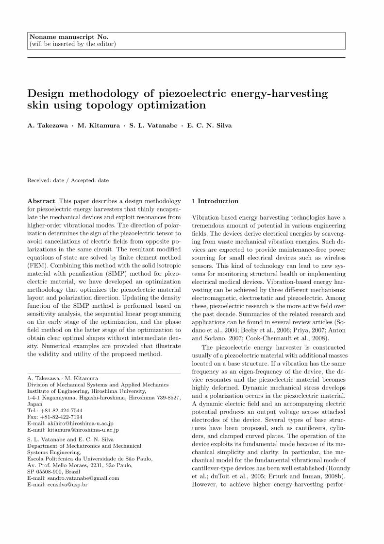
The simple models of this type are shown in Figure
1(a). The direction of polarization depends on the di-
rection of in-plane stress applied to the piezoelectricmaterial. Depending on the base-plate deformation, thedirection of stress can be different in the piezoelectric
material. The polarization directions will also be dif-ferent in the piezoelectric material as shown in Figure1(b). Since the piezoelectric material is sandwiched be-
tween electrodes, the electric field established by thesepolarizations approximately cancel each other result-ing in a very small field between these electrodes. To
prevent cancellations, the piezoelectric material needsto be separated on the nodes of vibration with polingdirection properly constructed at the fabrication stage
to unify the direction of polarization in the circuit, asshown in Figure 1(c). Another way is that the circuitshould be constructed on each part of the piezoelectric
layer (Kim et al., 2005a,b).
Figure 1 is about here.
Finding the optimal poling directions is the preserveof piezoelectric actuator design optimization. The ba-
sic method to construct an optimal circuit is to set thedesign variable that determines the sign of piezoelec-tric tensor and optimize it (Kogl and Silva, 2005). In
designing piezoelectric actuators or energy harvesterswith complicated shapes, the optimal circuit construc-tion is certainly hard to find without solving non-linear
optimization problem. However, in the case of energyharvesters operating in the d31 mode as shown in Fig-ure 1(b), the circuit design concept is analytically ex-
plained as shown in Figure 1(c). Since the direction ofpolarization depends on the direction of in-plane stressapplied to the piezoelectric material, the poling direc-
tion should be changed according to the direction of theapplied stress. In this research, we implement this pro-cedure to the equations of state and find optimal poling
direction by solving the modified equations of state asfollows:
σ = Cε− esTE (7)
D = esε+ ϵSE (8)
where
es = se (9)
s =eεz|eεz|
(10)
where s is a variable depending on the polarization di-rection, e the original piezoelectric tensor and eεz is
z-element of the polarization term eε. These modified
4 A. Takezawa et al.
state equations can be regarded as non-linear equations
now parameterized by the value of the state-dependentcoefficient s. The distribution of s at the convergedstate represents the optimal poling directions.
For solving by FEM, the above modified equationsof state are represented in the weak form:
−m(u,v) + a(u,v)− b(v, V ) = Lm(v) (11)
b(u, w) + c(V,w) = Le(w) (12)
with
m(u,v) = ωinput2
∫Ω
ρuvdx (13)
a(u,v) =
∫Ω
ε(u)TCε(v)dx (14)
b(u, w) =
∫Ω
ε(u)TesE(w)dx (15)
c(V,w) =
∫Ω
E(V )T ϵE(w)dx (16)
Lm(v) =
∫Γm
tvds (17)
Le(w) =
∫Γe
σwds, (18)
where v and w are test functions, t represent the trac-tions on Γm, and σ the surface charges on Γe. During
optimization, we fix Γm and Γe independently of thevalues of the design variables.
2.2 Objective function
The objective function of the optimization problem is
the electromechanical coupling coefficient k defined asfollows (Berlincourt et al., 1964):
k2 =Eem
2
EeEm=
b(u, V )2
a(u,u)c(V, V )(19)
where Eem, Ee, and Em are the electromechanical en-ergy, the electrical energy and the mechanical (strain)
energy respectively. If no charges lie on the boundary,substituting Equation (12) into Equation (19), k is sim-plified as follows:
k =Ee
Em(20)
Finally, we define the minimization of the inverse ofk as the objective function in optimizing the piezoelec-
tric domain Ωp,
minimizeΩp
1
k=
Em
Ee. (21)
2.3 Topology optimization
To optimize the geometry of Ωp, we used topology op-
timization method as this can perform more funda-mental optimizations over arbitrary domains includingshape and topology, as specified by the number of holes.
The fundamental idea is to introduce a fixed, extendeddesign domain D that includes, a priori, the optimalshape Ωopt and the utilization of the following charac-
teristic function:
χ(x) =
1 if x ∈ Ωopt
−1 if x ∈ D \Ωopt(22)
Using this function, the original design problem for Ωis replaced by a material distribution problem incorpo-
rating a physical property, χA, in the extended designdomainD, where A is a physical property of the originalmaterial comprising Ω. Unfortunately, the optimization
problem does not have any optimal solutions (Allaire,2001). A homogenization method is used to perform therelaxation of the solution space (Bendsøe and Kikuchi,
1988; Allaire, 2001). In this way, the original materialdistribution optimization problem with respect to thecharacteristic function is replaced by an optimization
problem of the “composite” consisting of the originalmaterial and a very weak material mimicking voids withrespect to the density function. This density function
represents the volume fraction of the original materialand can be regarded as a weak limit of the characteris-tic function. In optimization problems, the relationship
between the material properties of the composite andthe density function must be defined. We use here oneof the more popular ways, the “solid isotropic material
with penalization” (SIMP) method, which introduces acompletely artificial material property (Bendsøe, 1989;Bendsøe and Sigmund, 1999; Zhou and Rozvany, 1991).
In this method, quantities relating the three materialproperties of the composite used in thermoelectric anal-ysis, viz. elastic tensor C, piezoelectricity tensor e, per-
mittivity tensor ϵ, and density ρ, are set as functionsof the density of the penalization material ϕ:
C∗ = ϕpCC0 (23)
e∗ = ϕpee0 (24)
ϵ∗ = ϕpϵϵ0 (25)
ρ∗ = ϕpρρ0 (26)
0 < ϕ ≤ 1, (27)
where the upper suffix ∗ signifies that the material prop-erty relates to the composite, the lower suffix o to theoriginal material, and pC , pe, pϵ, and pρ are exponents
introduced as positive penalization parameters. The above
Design methodology of piezoelectric energy-harvesting skin using topology optimization 5
density function is defined only over domain Ωp which
determines D in Equation (22).Finally, the optimization problem with the addition
of a volume constraint is formulated as follows:
minimizeϕ
1
k=
Em
Ee(28)
and∫Ωp
ϕdx ≤ UV (29)
where UV is the upper limit of the volume.
2.4 Sensitivity analysis
To perform optimizations, we used the SLP technique,which requires first-order sensitivity analysis of the ob-jective function with respect to the design variable ϕ.
Since the derivation is lengthy, only the results areshown here and the detailed derivation is outlined inthe Appendix.
The two adjoint variables p and q are introduced toevaluate the sensitivity of the objective function whichdepends on the two state variables u and V . The sensi-
tivity of the objective function with respect to functionϕ is represented as an independent type of objectivefunction:
J ′(ϕ) =− ωinput2ρ′(ϕ)up+ ε(u)TC ′(ϕ)ε(p)
− ε(p)Te′s(ϕ)E(V ) + ε(u)Te′s(ϕ)E(q)
−E(V )T ϵ′(ϕ)E(q).
(30)
where p and q are adjoint variables which depends on
the objective function.The sensitivity of the electrochemical coupling fac-
tor k is calculated as follows:
k′(ϕ) =
(Em
Ee
)′
=E′
m(ϕ)Ee − EmE′e(ϕ)
Ee2 (31)
To calculate the sensitivity of the mechanical energya(u,u), the adjoint variables p and q must be obtained
by solving the following coupled adjoint equations:−m(v,p) + a(v,p) + b(v, q) = −2a(u,v)p = 0 on Γu
(32)−b(p, w)− c(q, w) = 0q = 0 on ΓV
(33)
and similarly for the mechanical energy c(V, V ):−m(p,v) + a(p,v) + b(v, q) = 0p = 0 on Γu
(34)b(p, w) + c(q, w) = 2c(V,w)q = 0 on ΓV .
(35)
3 Numerical Implementation
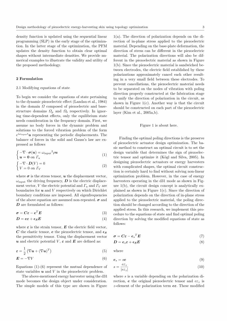
3.1 Algorithm
The optimization procedure is performed using an algo-rithm incorporating the sensitivity calculation and up-dating the design variable using SLP and PFM (Takezawa
et al., 2010). SLP is used at the early stage of the opti-mization with the so-called density filter (Bruns et al.,2002). PFM is used at the latter stage of the optimiza-
tion to obtain clear optimal shapes without intermedi-ate densities. The optimization algorithm is shown infigure 2.
Figure 2 is about here.
3.2 Discretization for FEM
FEM is used in this study to solve the modified equa-tions of state. The internal approximations of the weak
form of the modified equations of state in Equations(11)-(18) are first formulated as follows:
−m(uh,vh) + a(uh,vh)− b(vh, Vh) = Lm(vh) (36)
b(uh, wh) + c(Vh, wh) = Le(wh). (37)
The lowered suffix h indicates the discretized values.For simplicity, the discretized value of the state vari-ables are approximated using the shape functions Nj of
the first-order Lagrange finite elements correspondingto j-th nodes in accord with the following:
uh(x) =
Nd∑j=1
Nj(x)uh(xj) (38)
Vh(x) =Nd∑j=1
Nj(x)Vh(xj), (39)
where xj is the position of j-th node. Finally, by com-bining the state equations into one equation and intro-ducing the discretized test functions v(x) =
∑Ndj=1 Nj(x) =∑Nd
j=1 Nj(x)1 1 1T and w(x) =∑Nd
j=1 Nj(x), theweak-form equations of state can be formulated in theirvector and matrix form:
(M +K)U = b (40)

6 A. Takezawa et al.
where
M =
[−Muu 0
0 0
](41)
K =
[Kuu −KuV
KuVT KV V
](42)
Muu = [m(Nj , Ni)]1≤i,j≤Nd(43)
Kuu = [a(Nj , Ni)]1≤i,j≤Nd(44)
KuV = [b(Nj , Ni)]1≤i,j≤Nd(45)
KV V = [c(Nj , Ni)]1≤i,j≤Nd(46)
U =
Uh
Vh
=
uh(xj)1≤j≤Nd
Vh(xj)1≤j≤Nd
(47)
b =
Lm(Ni)1≤i≤Nd
Le(Ni)1≤i≤Nd
. (48)
Since the discretized equation of state in (40) is non-linear resulting from the dependency of the coefficients
on the state variables, an iterative approach must beused to obtain solutions. We have used the residualminimization approach based on the Newton-Raphson
method (Belytschko et al., 2000) whereby the residualfor Equation (40) is defined as:
R = (Ru,RV ) = (M +K)U − b. (49)
The updating of the discretized state vector at the n-th
iteration Un is is obtained from
Un+1 = Un +∆Un = Un −(∂R(Un)
∂U
)−1
R(Un).
(50)
The increment ∆Un is calculated by solving the follow-ing linear system:
∂R(Un)
∂U∆Un = −R(Un), (51)
with the tangent matrix ∂R(Un)∂U evaluated as follows:
∂R(Un)
∂U=
[∂Ru
∂Uh
∂Ru
∂Vh∂RV
∂Uh
∂RV
∂Vh
]. (52)
Because the derivatives of the variable s in Equa-tion (10) vanish, the tangent matrix as a result equalsM+K. Note that, the converged non-linear state equa-
tions are slow to converge as the solution oscillatesdue to the varying sign of the piezoelectric coefficient.Thus, the Newton-Raphson calculation is performed
with specified iteration times, but is sufficient to ob-tain optimal poling direction.
The adjoint equations in Equations (32)-(35) are
also solved by FEM. Note that the modified piezoelec-tric tensor is independent of adjoint variables p and q.Thus, these adjoint equations are linear and the solu-
tions can be obtained without any iterations.
3.3 Phase field method for shape optimization
PFM for shape optimization (Takezawa et al., 2010),which is used in the latter stage of the optimization
procedure, is outlined. The method uses the identicaldomain representation and sensitivity analysis as thedensity function with the SIMP-based topology opti-
mization. Different from the ordinary SIMP, for whichthe design variable is updated by the gradient based op-timization method, the density function is updated by
solving the following PDE so-called Allen-Cahn equa-tion in the PFM.
∂ϕ
∂t= κ∇2ϕ− f ′(ϕ) (53)
with
f(ϕ) =1
4w(ϕ) + η
J ′(ϕ)
||J ′(ϕ)||g(ϕ) (54)
w(ϕ) = ϕ2(1− ϕ2) (55)
g(ϕ) = ϕ3(6ϕ2 − 15ϕ+ 10) (56)
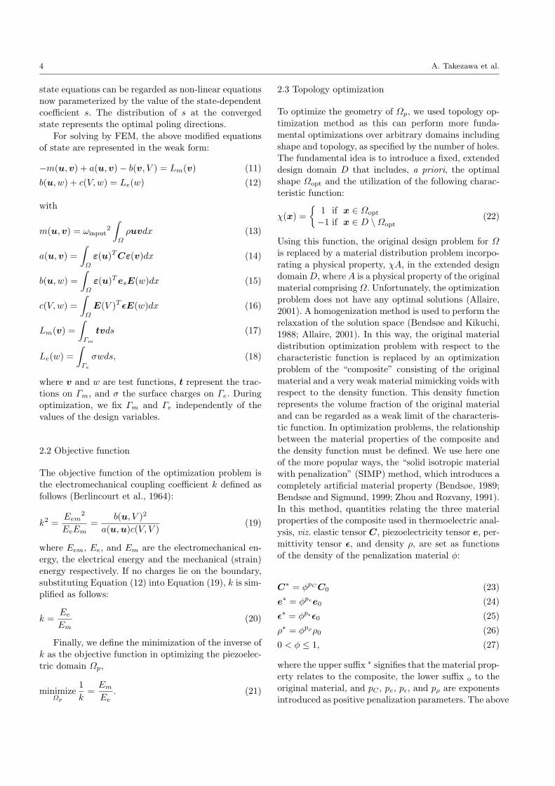
where t is the artificial time corresponding to the stepsize of the design variable, f is the asymmetric doublewell potential sketched in Figure 3, and η is a posi-
tive coefficient. Note f has two minimums on 0 and1. Because of couplings between diffusion and reactionterms in Equation (53), the density function ϕ is di-
vided into several domains corresponding to the value0 or 1. The so-called phase field interface correspond-ing to the intermediate values 0 < ϕ < 1 exists between
these domains. The interface moves into its normal di-rection according to the shape of the double well po-tential. Because the interface evolves in the direction of
the lower minimum of the potential, the density func-tion is updated based on the sensitivity analysis as inconventional steepest descent methods. As a result, the
optimal shape has clear 0 or 1 domains and negligiblethin phase field interface. Equation (53) is numericallysolved by the semi-implicit method which is a type of
finite difference method (Warren et al., 2003).
Figure 3 is about here.
4 Numerical Examples
The following numerical examples are provided to con-
firm the validity and the utility of the proposed method-ology. In all examples, the piezoelectric layers are madefrom transversely-isotropic PZT-5H, the material prop-
erties of which are listed in Table 1. For base structures,

Design methodology of piezoelectric energy-harvesting skin using topology optimization 7
we use isotropic aluminum with Young’s modulus E of
73[Gpa], Poisson’s ratio ν and electric conductivity σ of3.774×107[S/m]. The aluminum layer also functions asan electrode. The density function ϕ is only set on the
piezoelectric layer, that is, we only optimize the distri-bution of the piezoelectric material. The optimizationproblem in Equations (28) and (29) is solved according
to the algorithm set out in Figure 2. The penalizationparameters pc, pe, pϵ, and pρ in Equations (23)-(27)are set to 3, 3, 1, and 1, respectively. The positive co-
efficient η in Equation (55) is set to 10. At each itera-tion, we perform a finite element analysis of the stateequation and one update of the evolution equation for
the phase field function by solving the finite differenceequation of the semi-implicit scheme. The time step∆t is set to 0.9 times the limit of the Courant num-
ber. All FEM are performed using the commercial soft-ware COMSOL Multiphysics for quick implementationof the proposed methodology, and to effectively solvethe equations of state and adjoint with a multi-core
processor. The frequency response problem is solved bythe direct method.
Table 1 is about here.
4.1 Polarization optimization of clamped circular plate
As the first benchmark example, a polarization opti-
mization of clamped circular plate is performed, whichhas analytical optima discussed in (Kim et al., 2005a,b)and is used as a benchmark in (Rupp et al., 2009). Fig-
ure 4 shows a schematic diagram of the design objectstructure as a 25[mm] radius circular plate clampedat its edge. The top layer of the plate is composed
of piezoelectric material with a thickness of 0.127[mm]and the bottom layer of aluminum with a thicknessof 0.508[mm]. The upper surface of the structure is
grounded. The open circuit voltage is measured be-tween the top and bottom surfaces of the structure un-der a pressure of 9.65[kPa] applied to the bottom sur-
face. As both compression and stretching stresses areapplied to different parts of the piezoelectric layer, thecircuit should be separated to avoid cancellation of the
electric field. The distance between the circuit borderand the center is represented as r1. The border is de-cided based on the distribution of s obtained by solving
Equations (11)-(18) by FEM. A color bar is attachedto the figure to provide greater clarity although s is adiscrete variable having only two values −1 and 1. The
domain is represented as being a 2D axi-symmetrical
disk discretized by 200× 4 rectangular mesh with each
element treated as a first-order iso-parametric element.
Figure 4 is about here.
Figure 5 displays the resulting distribution of thevariable s obtained from the Newton-Raphson methodafter five iterations. Since s is plotted at the Gauss point
of each element, its value can be different in each ele-ment and a gray scaling can be observed as seen inthe domain 0.0152 ≤ r1 ≤ 0.0196. We determined the
border on which the polarization direction becomes re-versed at the center of the gray domain, that is, r1 =0.0175 and r1/r0 = 0.7. Figure 6 shows the variation of
the output voltage with r1/r0 from 0 to 1. The verti-cal dotted line represents the resultant position of thepolarization border r1/r0 = 0.7. According to Figure 6,
the global optima occurs at r1/r0 = 0.71. Although ourresult has about 1% error, the proposed method canbe considered as having performed well at finding the
optimal polarization direction.
Figures 5 and 6 are about here.
4.2 Polarization and topology optimization forcantilever energy harvester
A simultaneous optimization of the polarization and thelayout of the piezoelectric material is performed as thesecond example. The cantilever-type energy harvester
shown in Figure 7 is used as design object. The de-vice is composed of a 0.5[mm]-thick top layer of piezo-electric material and a 1.5[mm]-thick bottom layer of
aluminum. A periodic displacement input is initiatedfrom the left side (see figure) using the so-called largemass method; masses 1×10⁷[kg] are placed at the input
nodes and a unit force applied there along z-direction.The accelerations of the masses are set to 9.8[m/s2].No displacements are set for the x and y direction. The
1.5×10⁵[kg/m3] distributed mass is placed on the righthand edge of the structure. Ground is set on the up-per side of the structure. Neither surface traction nor
surface electric charge are applied to the structure. Inthis type of energy harvester, the first vibrational mode,having only one anti-node domain, is usually used for
power generation, as oscillations at higher frequencieshaving two or more anti-node domains are impractical.However, these vibrational modes are taken into consid-
eration in this example as a numerical benchmark for

8 A. Takezawa et al.
the proposed method. In the higher vibrational modes,
the polarization optimization is required to avoid thecancellation of electric field, in similar manner to thefirst example. The piezoelectric material layer and the
substrate layer are discretized by 100 × 50 × 1 and100× 50× 2 cuboid meshes respectively. Each elementforms a first-order iso-parametric element. To reduce
computational demands, the variable s in Equation (10)is fixed to 1 × 10⁻³ at the position where |εez| is lessthan 1% of the average value of |εez|. Three iterations
within the Newton-Raphson method are performed tosolve the state equations in each optimization iteration.The volume constraint is set to 60% of the total volume
of the piezoelectric layer.
Figure 7 is about here.
Note that the proposed method can not specify themode shape and the corresponding harmonic frequencyof the resulting optimal structure because we treated
only the electromechanical coupling factor as the ob-jective function. However, because the base plate layerhas three times the thickness of the piezoelectric layer,
the harmonic frequency of the whole structure will notchange significantly. Thus, based on the frequency re-sponse of the initial structure, the preferred modal shapes
for energy harvesting need to be determined, and thecorresponding harmonic frequency estimated. We usethe two types of structures for which the density func-
tions ρ of the piezoelectric material are uniformly setto 1 or 0.1, and the variable s set to 1 over the wholedomain. The structure shall be referred to as the “fully-
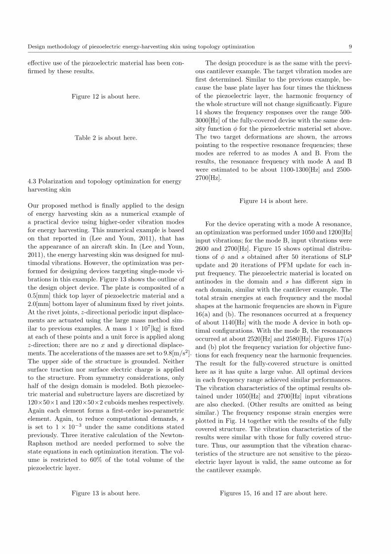
covered structure” hereafter. Figure 8 shows the strainenergy for each structure subjected to an input vibra-tion in the frequency range 500-2500[Hz]. The deformed
shapes in the x-y plane at the center of piezoelectriclayer associated with the three anti-node domain is alsoshown in this graph at the corresponding frequency. Ac-
cording to the results, the resonance frequency of theoptimal structure operating under the target modes canbe estimated to be about 1800-2000[Hz].
Figure 8 is about here.
Input vibrations at frequencies of 1800 and 2000[Hz]are used in the optimization. Figure 9 shows optimaldistribution of ϕ and s obtained after 50 iterations of
SLP update and 20 iterations of PFM updates. Ac-cording to the results, the piezoelectric layer should bedivided into three parts in the domain each part cor-
responding to an antinode. Figure 10 shows the total
strain energy for each optimal structure over the 1750-
2250[Hz] input frequency range and the deformationsat the resonance frequencies. The harmonic frequenciesof both structures are about 1900[Hz] and 1980[Hz] and
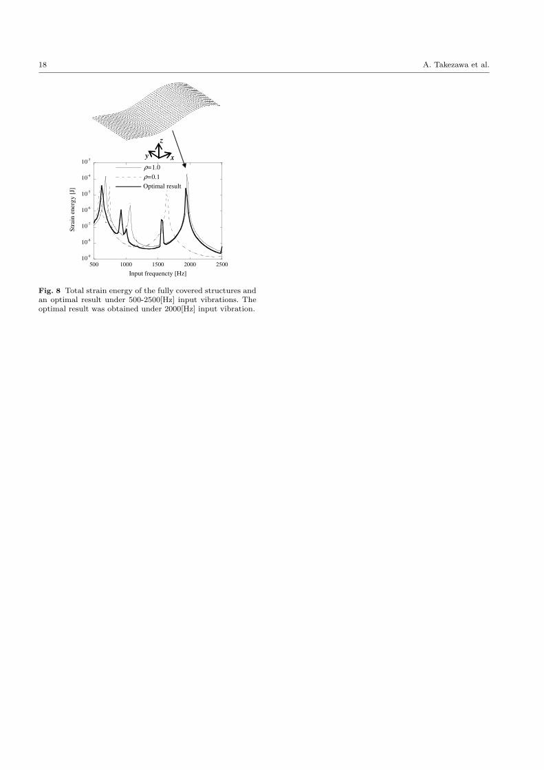
the deformations at these harmonic frequencies are al-most identical to those expected. Figure 11 plots theobjective functions of each structure in the frequency
range 1900-2050[Hz]. Both optimal structures displayfiner-tuned performances at their harmonic frequencies.The vibration characteristic of the optimal result ob-
tained under a 2000[Hz] vibrational input is also checked.(Being similar, the result for a 1800[Hz] input is omit-ted.) The frequency response strain energies were plot-
ted in Fig. 8 together with the results for the fully cov-ered structure. The vibration characteristic of the re-sults was similar with that for the fully covered struc-ture with ρ = 1.0. Thus, our assumption that the vi-
bration characteristic of the structure is not sensitiveto the piezoelectric layer layout is valid.
Figures 9, 10 and 11 are about here.
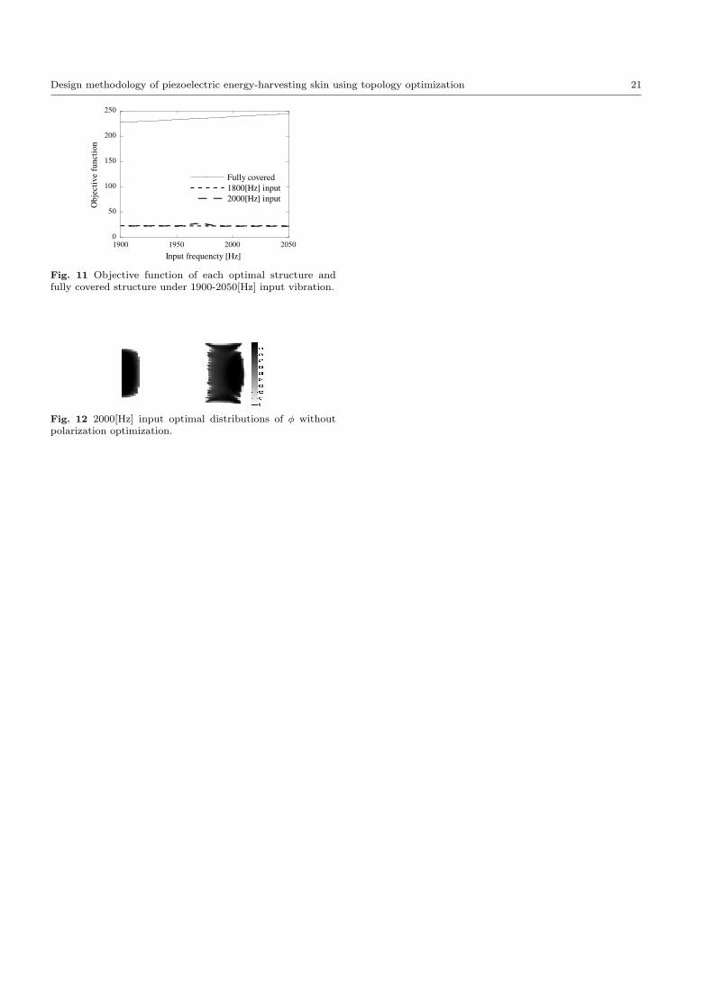
Finally, the performance of the proposed method iscompared with that for conventional topology optimiza-
tions of piezoelectric layers without polarization opti-mization. The original equations of state in Equations(1)-(6) are used for FEM in this example. The frequen-
cies chosen for the input vibration were 1800[Hz] re-spectively. Figure 12 shows the optimal distribution forϕ. Blocks of piezoelectric layer are found only in parts
of domain corresponding to antinodes although differ-ent parts from the previous examples with polarizationoptimization.
Table 2 shows the performance comparison amongoptimal devices and the fully-covered devices with andwithout polarization optimization. The optimal and the
fully-covered devices with optimal polarizations clearlyachieved higher performances than those without opti-mal polarizations. The reason is clear considering that
all domain parts corresponding to antinodes can beused in power generation given optimal polarization.Without polarization optimization, if electrodes con-
nect the top and bottom of the piezoelectric layers andthe vibrational mode has multiple nodes, the piezo-electric material must be located on only one side of
the antinodes to avoid cancellation of power generatingcontributions. In contrast, by comparing optimal andfully-covered devices, both with optimal polarizations,
the optimal device achieved about 86% performancewith only about 53% of the piezoelectric material inthe fully-covered device. The advantage of integrating
polarization and topology optimizations in terms of the
Design methodology of piezoelectric energy-harvesting skin using topology optimization 9
effective use of the piezoelectric material has been con-
firmed by these results.
Figure 12 is about here.
Table 2 is about here.
4.3 Polarization and topology optimization for energyharvesting skin
Our proposed method is finally applied to the designof energy harvesting skin as a numerical example ofa practical device using higher-order vibration modes
for energy harvesting. This numerical example is basedon that reported in (Lee and Youn, 2011), that hasthe appearance of an aircraft skin. In (Lee and Youn,
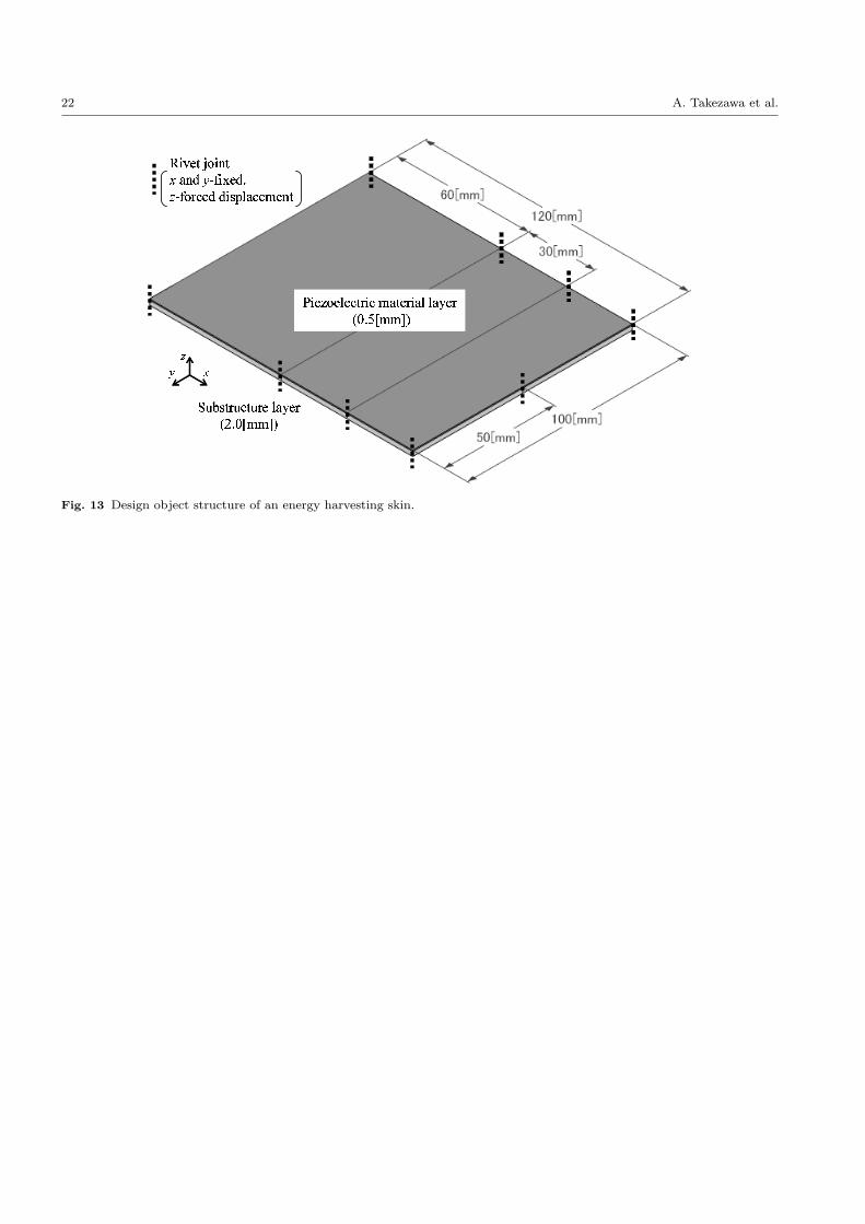
2011), the energy harvesting skin was designed for mul-timodal vibrations. However, the optimization was per-formed for designing devices targeting single-mode vi-brations in this example. Figure 13 shows the outline of
the design object device. The plate is composited of a0.5[mm] thick top layer of piezoelectric material and a2.0[mm] bottom layer of aluminum fixed by rivet joints.
At the rivet joints, z-directional periodic input displace-ments are actuated using the large mass method sim-ilar to previous examples. A mass 1 × 10⁷[kg] is fixed
at each of these points and a unit force is applied alongz-direction; there are no x and y directional displace-ments. The accelerations of the masses are set to 9.8[m/s2].
The upper side of the structure is grounded. Neithersurface traction nor surface electric charge is appliedto the structure. From symmetry considerations, only
half of the design domain is modeled. Both piezoelec-tric material and substructure layers are discretized by120×50×1 and 120×50×2 cuboids meshes respectively.
Again each element forms a first-order iso-parametricelement. Again, to reduce computational demands, sis set to 1 × 10⁻³ under the same conditions stated
previously. Three iterative calculation of the Newton-Raphson method are needed performed to solve thestate equations in each optimization iteration. The vol-
ume is restricted to 60% of the total volume of thepiezoelectric layer.
Figure 13 is about here.
The design procedure is as the same with the previ-
ous cantilever example. The target vibration modes arefirst determined. Similar to the previous example, be-cause the base plate layer has four times the thickness
of the piezoelectric layer, the harmonic frequency ofthe whole structure will not change significantly. Figure14 shows the frequency responses over the range 500-
3000[Hz] of the fully-covered devise with the same den-sity function ϕ for the piezoelectric material set above.The two target deformations are shown, the arrows
pointing to the respective resonance frequencies; thesemodes are referred to as modes A and B. From theresults, the resonance frequency with mode A and B
were estimated to be about 1100-1300[Hz] and 2500-2700[Hz].
Figure 14 is about here.
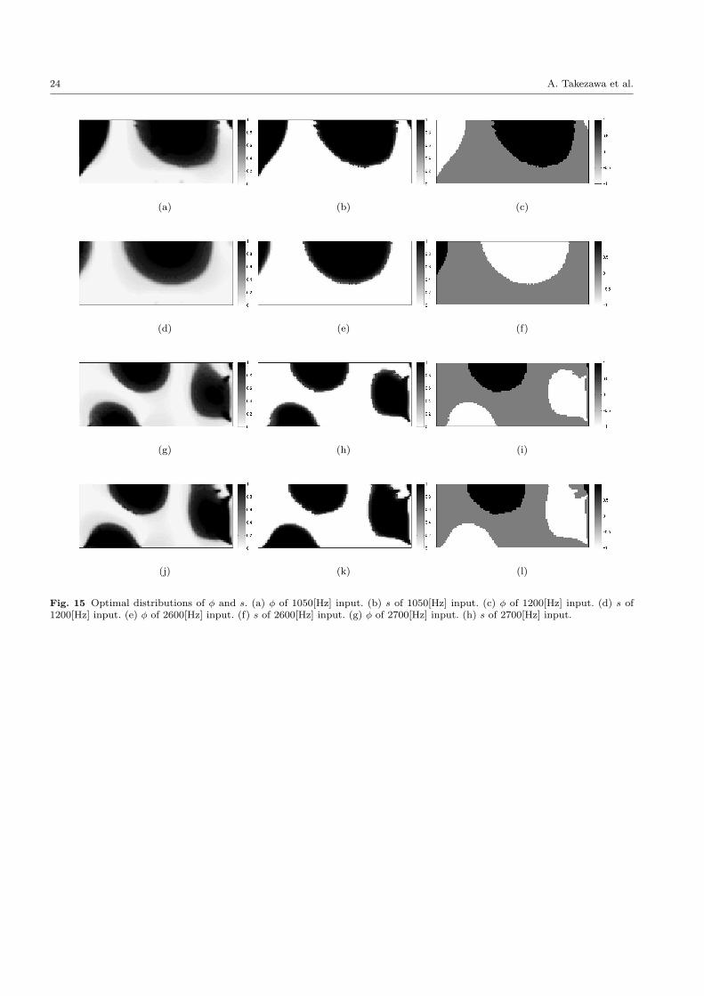
For the device operating with a mode A resonance,an optimization was performed under 1050 and 1200[Hz]input vibrations; for the mode B, input vibrations were
2600 and 2700[Hz]. Figure 15 shows optimal distribu-tions of ϕ and s obtained after 50 iterations of SLPupdate and 20 iterations of PFM update for each in-
put frequency. The piezoelectric material is located onantinodes in the domain and s has different sign ineach domain, similar with the cantilever example. The
total strain energies at each frequency and the modalshapes at the harmonic frequencies are shown in Figure16(a) and (b). The resonances occurred at a frequency
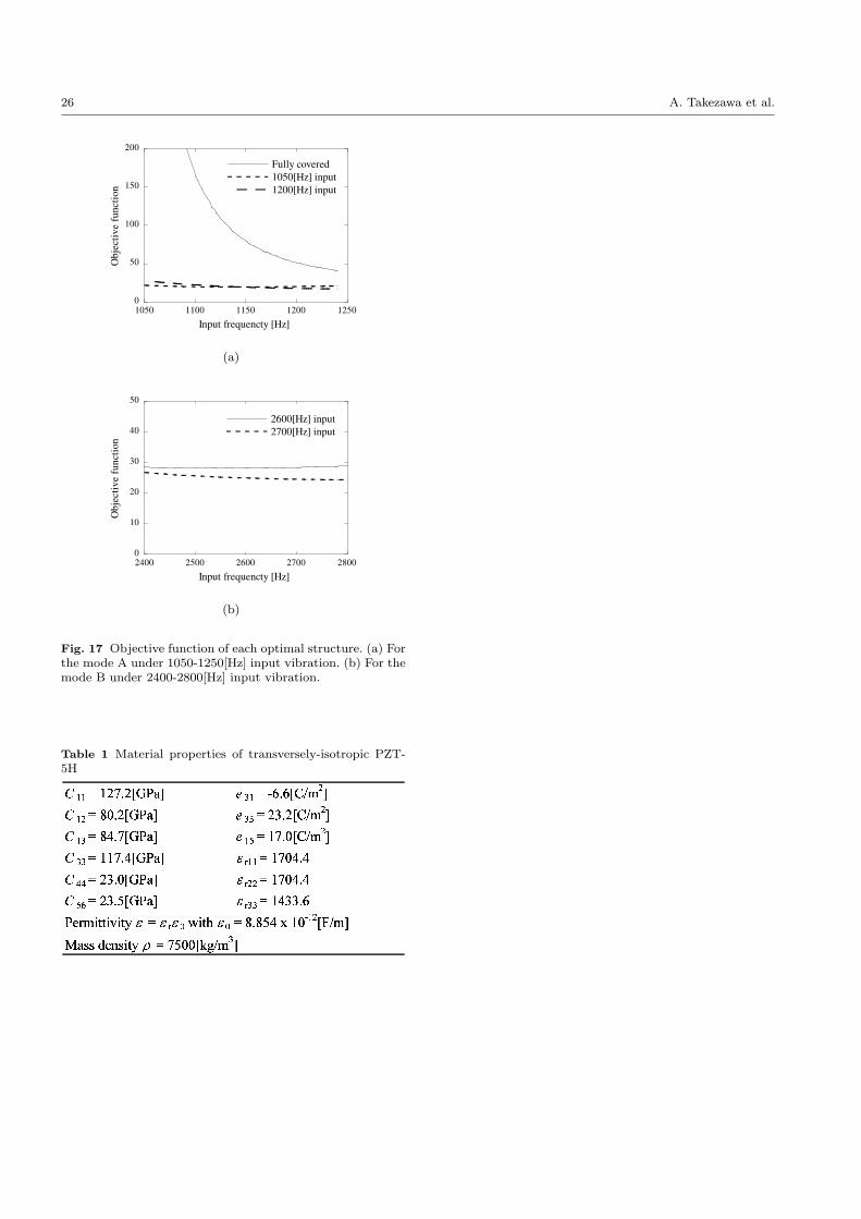
of about 1140[Hz] with the mode A device in both op-timal configurations. With the mode B, the resonancesoccurred at about 2520[Hz] and 2580[Hz]. Figures 17(a)
and (b) plot the frequency variation for objective func-tions for each frequency near the harmonic frequencies.The result for the fully-covered structure is omitted
here as it has quite a large value. All optimal devicesin each frequency range achieved similar performances.The vibration characteristics of the optimal results ob-
tained under 1050[Hz] and 2700[Hz] input vibrationsare also checked. (Other results are omitted as beingsimilar.) The frequency response strain energies were
plotted in Fig. 14 together with the results of the fullycovered structure. The vibration characteristics of theresults were similar with those for fully covered struc-
ture. Thus, our assumption that the vibration charac-teristics of the structure are not sensitive to the piezo-electric layer layout is valid, the same outcome as for
the cantilever example.
Figures 15, 16 and 17 are about here.
10 A. Takezawa et al.
Table 3 shows a performance comparison at 1050[Hz]
and 2700[Hz] input frequencies for the resulting topology-optimized devices and the fully-covered devices withand without polarization optimization. The topology-
optimized device clearly achieved higher performancesthan the fully-covered device without optimal polariza-tions. Moreover, this exceeded even the fully-covered
device with optimal polarization, in contrast to the pre-vious cantilever-type device. As shown in Figure 14, thedeformations covered a wider domain that also included
nodes, compared to the cantilever-type device. This isdue to the rivet joint connection around the structure.Thus, in the fully-covered structure, the piezoelectric
material can lie redundant even if the polarization isoptimized. Moreover, the excess piezoelectric materialmakes the structure stiffer because of an anti-piezoelectric
effect. Thus, this numerical example confirms the effec-tiveness of the proposed method in designing energyharvesting skins.
Table 3 is about here.
5 Conclusion
We have proposed a geometrical optimization methodfor piezoelectric energy harvesters using higher-ordervibrational modes. Modified equations of state, for which
the sign of the piezoelectric tensor depends on the di-rection of polarization, were established so that optimalpoling directions can be found while avoiding cancella-
tions of the electric fields due to opposite polarizationsin the same circuit. The modified equations of state arenonlinear partial differential equations that are solved
by FEM. Combining this methodology with the conven-tional SIMP method for piezoelectric material, an opti-mization method has been developed for designing the
piezoelectric material layout and polarization direction.Updating the density function of the SIMP method wasperformed based on sensitivity analysis, the sequential
linear programming (SLP) and the phase field method(PFM). The numerical examples provided illustrate thevalidity and utility of the proposed methodology.
The optimal topology and poling directions obtained
can be implemented by ordinary means. Because the en-ergy harvesting skin is built by attaching a piezoelectricplate on the surface of the vibrating device, the optimal
result can be actualized by cutting the plate accordingto the optimal shape and attaching it face-up or downin accordance with the optimal poling direction. Al-
though the generating power is lower, PolyVinylidene
DiFluoride (PVDF) piezoelectric film could make man-
ufacturing easier.This methodology was considered to be especially
effective designing the device using complicated vibra-
tional modes such as those used in energy harvestingskins (Lee and Youn, 2011). As shown by this example,to find the optimal location of piezoelectric material is
important to improve device performance and reducethe total use and cost of the material. To perform alsotopology optimizations under various vibrations with
complicated deformations, the poling direction must beoptimized at each iteration. The proposed method ob-tained approximated optimal directions using nonlinear
FEM.Following on from the work described in this paper,
there are some opportunities for further research. First,
we ignored for simplicity sake some important factors ofthe vibration-based energy harvesting in the numericalexamples. These factors include adjusting the harmonicfrequency to the specified frequency of the input vibra-
tion, constructing a closed circuit and finding optimalvalue of the resister, and a parametrical study of somegeometrical size; these are basic important design con-
siderations for energy harvesting devices. Moreover, thecurrently proposed methodology cannot apply if eigen-frequencies are repeated near the target frequency. To
confirm the utility of the proposed method in the designof energy harvesters, we require the simultaneous opti-mization of the poling direction, the layout of the piezo-
electric material, and the above-mentioned factors.Second, aside from the structural problem, the elec-
tric circuit or its controls affect strongly the perfor-
mance of the energy harvester (Makihara et al., 2006).Although only the open circuit model has been con-sidered, the optimization should be performed based
on real circuit settings so that realistically-designed de-vices can be studied.
References
G. Allaire. Shape Optimization by the HomogenizationMethod. Springer-Verlag, New York, 2001.
G. Allaire. Conception Optimale De Structures.
Springer-Verlag, Berlin, 2007.G. Allaire, F. Jouve, and A. M. Toader. Structuraloptimization using sensitivity analysis and a level-set
method. J. Comput. Phys., 194(1):363–393, 2004.S. R. Anton and H. A. Sodano. A review of powerharvesting using piezoelectric materials (2003–2006).
Smart Mater. Struct., 16:R1, 2007.S. P. Beeby, M. J. Tudor, and N. M. White. Energyharvesting vibration sources for microsystems appli-
cations. Meas. Sci. Technol., 17:R175, 2006.

Design methodology of piezoelectric energy-harvesting skin using topology optimization 11
T. Belytschko, W. K. Liu, and B. Moran. Nonlinear
Finite Elements for Continua and Structures. Wiley,Chichester, 2000.
M. P. Bendsøe. Optimal shape design as a material
distribution problem. Struct. Optim., 1(4):193–202,1989.
M. P. Bendsøe and N. Kikuchi. Generating optimal
topologies in structural design using a homogeniza-tion method. Comput. Meth. Appl. Mech. Eng., 71(2):197–224, 1988.
M. P. Bendsøe and O. Sigmund. Material interpolationschemes in topology optimization. Arch. Appl. Mech.,69(9):635–654, 1999.
M. P. Bendsøe and O. Sigmund. Topology Optimization:Theory, Methods, and Applications. Springer-Verlag,Berlin, 2003.
D. A. Berlincourt, D. R. Curran, and H. Jaffe. Piezo-electric and piezomagnetic materials and their func-tion in transducers. In : Physical acoustics, Principleand methods. Vol.1, Part A, W. P. Mason, Ed, Aca-
demic Press, pages 169–270, 1964.R.I. Bourisli and M.A. Al-Ajmi. Optimization of smartbeams for maximum modal electromechanical cou-
pling using genetic algorithms. J. Intell. Mater. Syst.Struct., 21(9):907–914, 2010.
T. E. Bruns, O. Sigmund, and D. A. Tortorelli. Nu-
merical methods for the topology optimization ofstructures that exhibit snap-through. Int. J. Numer.Meth. Eng., 55(10):1215–1237, 2002.
S. Chen, S. Gonella, W. Chen, and W. K. Liu. A levelset approach for optimal design of smart energy har-vesters. Comput. Meth. Appl. Mech. Eng., 199(37-
40):2532–2543, 2010.K. A. Cook-Chennault, N. Thambi, and A. M. Sastry.Powering mems portable devices - a review of non-
regenerative and regenerative power supply systemswith special emphasis on piezoelectric energy har-vesting systems. Smart Mater. Struct., 17:043001,
2008.N. E. duToit, B. L. Wardle, and S. G. Kim. Designconsiderations for mems-scale piezoelectric mechan-
ical vibration energy harvesters. Integrated Ferro-electrics, 71:121–160, 2005.
A. Erturk and D. J. Inman. A distributed parameter
electromechanical model for cantilevered piezoelec-tric energy harvesters. J. Vib. Acoust., 130:041002,2008a.
A. Erturk and D.J. Inman. On mechanical model-ing of cantilevered piezoelectric vibration energy har-vesters. J. Intell. Mater. Syst. Struct., 19(11):1311–
1325, 2008b.A. Erturk, P. A. Tarazaga, J. R. Farmer, and D. J.Inman. Effect of strain nodes and electrode config-
uration on piezoelectric energy harvesting from can-
tilevered beams. J. Vib. Acoust., 131:011010, 2009.S. Gonella, A.C. To, and W.K. Liu. Interplay betweenphononic bandgaps and piezoelectric microstructures
for energy harvesting. J. Mech. Phys. Solid., 57(3):621–633, 2009.
J. E. Kim, D. S. Kim, P. S. Ma, and Y. Y. Kim. Multi-
physics interpolation for the topology optimizationof piezoelectric systems. Comput. Meth. Appl. Mech.Eng., 199(49-52):3153–3168, 2010.
S. Kim, W. W. Clark, and Q. M. Wang. Piezoelec-tric energy harvesting with a clamped circular plate:analysis. J. Intell. Mater. Syst. Struct., 16(10):847–
854, 2005a.S. Kim, W.W. Clark, and Q.M. Wang. Piezoelectricenergy harvesting with a clamped circular plate: ex-perimental study. J. Intell. Mater. Syst. Struct., 16
(10):855–863, 2005b.M. Kogl and E.C.N. Silva. Topology optimization ofsmart structures: design of piezoelectric plate and
shell actuators. Smart Mater. Struct., 14:387–399,2005.
L. D. Landau, L. P. Pitaevskii, and E.M. Lifshitz. Elec-
trodynamics of Continuous Media, Second Edition.Butterworth-Heinemann, Oxford, 1984.
C. Lee and J. Xie. Design and optimization of wafer
bonding packaged microelectromechanical systemsthermoelectric power generators with heat dissipa-tion path. J. Vac. Sci. Technol. B, 27:1267–1271,
2009.S. Lee and B. D. Youn. A new piezoelectric energyharvesting design concept: multimodal energy har-
vesting skin. IEEE Trans. Ultrason. Ferroelectrics.Freq. Contr., 58(3):629–645, 2011.
S. Lee, B.D. Youn, and B.C. Jung. Robust segment-
type energy harvester and its application to a wirelesssensor. Smart Mater. Struct., 18:095021, 2009.
K. Makihara, J. Onoda, and T. Miyakawa. Low en-
ergy dissipation electric circuit for energy harvesting.Smart Mater. Struct., 15:1493, 2006.
P. H. Nakasone and E. C. N. Silva. Dynamic design of
piezoelectric laminated sensors and actuators usingtopology optimization. J. Intell. Mater. Syst. Struct.,21(16):1627–1652, 2010.
S. Priya. Advances in energy harvesting using low pro-file piezoelectric transducers. J. Electroceram., 19(1):167–184, 2007.
S. Roundy, P.K. Wright, and J. Rabaey. A study of lowlevel vibrations as a power source for wireless sensornodes. Comput. Comm., 26(11):1131–1144.
C.J. Rupp, A. Evgrafov, K. Maute, and M.L. Dunn.Design of piezoelectric energy harvesting systems: Atopology optimization approach based on multilayer

12 A. Takezawa et al.
plates and shells. J. Intell. Mater. Syst. Struct., 20
(16):1923–1939, 2009.H.A. Sodano, D.J. Inman, and G. Park. A review ofpower harvesting from vibration using piezoelectric
materials. Shock Vib. Digest, 36(3):197–206, 2004.K. H. Sun and Y. Y. Kim. Layout design optimiza-tion for magneto-electro-elastic laminate composites
for maximized energy conversion under mechanicalloading. Smart Mater. Struct., 19:055008, 2010.
Y. Tadesse, S. Zhang, and S. Priya. Multimodal energy
harvesting system: piezoelectric and electromagnetic.J. Intell. Mater. Syst. Struct., 20(5):625–623, 2009.
A. Takezawa, S. Nishiwaki, and M. Kitamura. Shape
and topology optimization based on the phasefieldmethod and sensitivity analysis. J. Comput. Phys.,229(7):2697–2718, 2010.
M. Y. Wang, X. Wang, and D. Guo. A level set methodfor structural topology optimization. Comput. Meth.Appl. Mech. Eng., 192(1-2):227–246, 2003.
J. A. Warren, R. Kobayashi, A. E. Lobkovsky, and
W. Craig Carter. Extending phase field models of so-lidification to polycrystalline materials. Acta Mater.,51(20):6035–6058, 2003.
B. Zheng, C. J. Chang, and H. C. Gea. Topology op-timization of energy harvesting devices using piezo-electric materials. Struct. Multidisc. Optim., 38(1):
17–23, 2009.M. Zhou and G. I. N. Rozvany. The coc algorithm. ii:Topological, geometrical and generalized shape opti-
mization. Comput. Meth. Appl. Mech. Eng., 89(1-3):309–336, 1991.
Appendix
In this appendix, the detailed derivation of the sensi-tivity in Equation (30) and the adjoint equations in
Equations (32)-(35) is outlined. The derivatives of theobjective functions with respect to the density func-tion are based on the procedure shown in Chapter 5 of
(Allaire, 2007). The general objective function of piezo-electric problem is defined as J(ϕ) =
∫j(u, V )dx. The
derivative of this function in the direction θ is then
⟨J ′(ϕ), θ⟩ =∫
j′(u)⟨u′(ϕ), θ⟩dx+
∫j′(V )⟨V ′(ϕ), θ⟩dx
=
∫j′(u)vdx+
∫j′(V )wdx
(57)
where v = ⟨u′(ϕ), θ⟩, w = ⟨V ′(ϕ), θ⟩. Setting adjointstates p and q as test functions of the weak-form equa-
tions of state in Equations (11)-(18), the Lagrangian is
formulated as follows:
L(ϕ,u, V,p, q)
=
∫j(u, V )dx−m(u,p) + a(u,p)− b(p, V )− Lm(p)
+ b(u, q) + c(V, q)− Le(q).
(58)
Using this, the derivative of the objective function canbe expressed as
⟨j′(ϕ), θ⟩
=
⟨∂L
∂ϕ(ϕ,u, V,p, q), θ
⟩+
⟨∂L
∂u(ϕ,u, V,p, q), ⟨u′(ϕ), θ⟩
⟩+
⟨∂L
∂V(ϕ,u, V,p, q), ⟨V ′(ϕ), θ⟩
⟩=
⟨∂L
∂ϕ(ϕ,u, V,p, q), θ
⟩+
⟨∂L
∂u(ϕ,u, V,p, q),v
⟩+
⟨∂L
∂V(ϕ,u, V,p, q), w
⟩.
(59)
Consider the case where the second and third terms arezero. These terms are calculated as follows:⟨∂L
∂u,v
⟩=
∫j′(u)vdx−m(v,p)+a(v,p)+b(v, q) = 0,
(60)⟨∂L
∂V,w
⟩=
∫j′(V )wdx− b(p, w) + c(w, q) = 0. (61)
When the adjoint states p and q satisfy the above ad-joint equations, the second and third terms of Equation(59) can be ignored. On the other hand, the derivatives
of Equations (11) - (18) with respect to ϕ in the direc-tion θ are
−m′(u,p)−m(v,p) + a′(u,p) + a(v,p)
−b′(p, V )− b(p, w) = 0(62)
b′(u, q) + b(p, q) + c′(V, q) + c(w, q) = 0 (63)
where
m′(u,p) = ωinput2
∫Ω
ρ′(ϕ)upθdx (64)
a′(u,p) =
∫Ω
ε(u)TC ′(ϕ)ε(p)θdx (65)
b′(p, V ) =
∫Ω
ε(p)Te′s(ϕ)E(V )θdx (66)
c′(V, q) =
∫Ω
E(V )T ϵ′(ϕ)E(q)θdx. (67)

Design methodology of piezoelectric energy-harvesting skin using topology optimization 13
Substituting Equations (62) and (63) into Equations
(60) and (61) and combining them into one equation,the following equation is obtained:∫
j′(u)vdx+
∫j′(V )wdx
=−m′(u,p) + a′(u,p)− b′(p, V ) + b′(u, q) + c′(V, q)
(68)
Substituting Equation (68) into Equation (57) yieldsfollowing equation:
J ′(ϕ) =− ωinput2ρ′(ϕ)up
+ ε(u)TC ′(ϕ)ε(p)− ε(p)Te′s(ϕ)E(V )
+ ε(u)Te′s(ϕ)E(q)−E(V )T ϵ′(ϕ)E(q).
(69)
Next, the adjoint equations are calculated from Equa-tions (60) and (61). When the electric energy c(V, V )is considered as the objective function, it is formulated
as follows:
J(ρ) =
∫j(u, V )dx
= c(V, V ).
(70)
Thus,∫j′(u)vdx = 0 (71)∫j′(V )wdx = 2c(V,w) (72)
Substituting Equations (71) and (72) into Equations
(60) and (61) respectively gives following equation
m(v,p)− a(v,p)− b(v, q) = 0 (73)
b(p, w) + c(w, q) = 2c(V,w) (74)
When the strain energy a(u,u) is considered as theobjective function, it is formulated as follows:
J(ρ) =
∫j(u, V )dx
= a(u,u)
(75)
Thus,∫j′(u)vdx = 2a(u,v) (76)∫j′(V )wdx = 0 (77)
Substituting Equations (76) and (77) into Equations(60) and (61) respectively gives following equation
2a(u,v)−m(p,v) + a(p,v) + b(v, q) = 0 (78)
−b(p, w) + c(q, w) = 0. (79)

14 A. Takezawa et al.
(a)
(b)
(c)
Fig. 1 Cross-sectional view of the deformed cantilever-typeenergy harvester. (a) With uni-directional polarization. (b)With bi-directional polarization. (c) Reversing poling direc-tion to avoid cancellation of the electric field
Set an initial value of density function φ
Calculate the state variables and the variable sby solving Equations (11)-(18) using FEM.
Calculate the objective functionand the constraints.
Calculate the adjoint variables by solvingEquations (31)-(34) using FEM.
Calculate the sensitivities ofthe objective function and the constraint.
Update density function φ using SLP or PFM
Converged?
End
Yes
No
Fig. 2 Flowchart of the optimization algorithm
o φ1
( )( )'
'
J
J
φη
φ
( )f φ
Fig. 3 The outline of the double well potential used in PFM

Design methodology of piezoelectric energy-harvesting skin using topology optimization 15
! "
#$# %
& #
Fig. 4 Cross-section view of the clamped circular energy harvester

16 A. Takezawa et al.
Fig. 5 Optimal distribution of s and analyzed polarizationborder
0
2
4
6
8
10
0 0.2 0.4 0.6 0.8 1
r1/r
0
Out
put v
olta
ge [
V]
Fig. 6 The relationship between the output voltage and theratio r1/r0

Design methodology of piezoelectric energy-harvesting skin using topology optimization 17
! "
# $ $ % &
' $&!&(
)*+
)*+
Fig. 7 Design object structure of cantilever type energy harvester
18 A. Takezawa et al.
z
xy
z
xyρ=1.0ρ=0.1Optimal result
10-9
10-8
10-7
10-6
10-5
10-4
10-3
500 1000 1500 2000 2500
Input frequencty [Hz]
Stra
in e
nerg
y [J
]
Fig. 8 Total strain energy of the fully covered structures andan optimal result under 500-2500[Hz] input vibrations. Theoptimal result was obtained under 2000[Hz] input vibration.

Design methodology of piezoelectric energy-harvesting skin using topology optimization 19
(a) (b) (c)
(d) (e) (f)
Fig. 9 Optimal distributions of ϕ and e. (a) ϕ of 1800[Hz] input after SLP update. (b) ϕ of 1800[Hz] input after PFM update.(c) e of 1800[Hz] input after PFM update. (d) ϕ of 2000[Hz] input after SLP update. (e) ϕ of 2000[Hz] input after PFM update.(f) e of 2000[Hz] input after PFM update.

20 A. Takezawa et al.
Str
ain
ener
gy
[J]
Input frequency [Hz]
z
xy
z
xy
1800 1900 2000 2100 220010
-9
10-8
10-7
10-6
10-5
10-4
10-2
10-1
100
101
|Vo
ltag
e| [
V]
SE of 1800[Hz] input|V| of 1800[Hz] input
SE of 2000[Hz] input|V| of 2000[Hz] input
Fig. 10 Total strain energy of each optimal structure under 1750-2250[Hz] input vibration.
Design methodology of piezoelectric energy-harvesting skin using topology optimization 21
0
50
100
150
200
250
1900 1950 2000 2050
Fully covered1800[Hz] input2000[Hz] input
Input frequencty [Hz]
Obj
ectiv
e fu
nctio
n
Fig. 11 Objective function of each optimal structure andfully covered structure under 1900-2050[Hz] input vibration.
Fig. 12 2000[Hz] input optimal distributions of ϕ withoutpolarization optimization.
22 A. Takezawa et al.
!
"# $ % & ' () +* ,
-./ . . 0 % & 1 ' ) 2 2* ,
345
345
Fig. 13 Design object structure of an energy harvesting skin.

Design methodology of piezoelectric energy-harvesting skin using topology optimization 23
10-10
10-9
10-8
10-7
10-6
10-5
10-4
10-3
10-2
500 1000 1500 2000 2500 3000
Input frequencty [Hz]
Stra
in e
nerg
y [J
]
ρ=1.0ρ=0.1
Optimal resultfor Mode AOptimal resultfor Mode B
z
xy
z
xy
Mode A Mode B
Fig. 14 Total strain energy of the fully covered structures and optimal results under 500-3000[Hz] input vibrations. Optimalresults for Mode A and B were obtained under 1050[Hz] and 2700[Hz] inputs respectively.
24 A. Takezawa et al.
(a) (b) (c)
(d) (e) (f)
(g) (h) (i)
(j) (k) (l)
Fig. 15 Optimal distributions of ϕ and s. (a) ϕ of 1050[Hz] input. (b) s of 1050[Hz] input. (c) ϕ of 1200[Hz] input. (d) s of1200[Hz] input. (e) ϕ of 2600[Hz] input. (f) s of 2600[Hz] input. (g) ϕ of 2700[Hz] input. (h) s of 2700[Hz] input.

Design methodology of piezoelectric energy-harvesting skin using topology optimization 25
Str
ain e
ner
gy
[J]
Input frequency [Hz]
900 1000 1100 1200 1300 1400
1050[Hz] input 1200[Hz] input
z
xy
z
xy
10-8
10-7
10-6
10-5
10-4
10-3
10-2
10-1
100
101
10210
-3SE of 1050[Hz] input|V| of 1050[Hz] input
SE of 1200[Hz] input|V| of 1200[Hz] input
|Volt
age|
[V
]
(a)
Str
ain
en
erg
y [
J]
Input frequency [Hz]
z
xy
z
xy
2300 2400 2500 2600 270010
-8
10-7
10-6
10-5
10-4
10-1
100
101
102
|Vo
ltag
e| [
V]
10-3
SE of 2600[Hz] input|V| of 2600[Hz] input
SE of 2700[Hz] input|V| of 2700[Hz] input
(b)
Fig. 16 Total strain energy of each optimal structure. (a) For the mode A under 900-1400[Hz] input vibration. (b) For themode B under 2250-2750[Hz] input vibration.
26 A. Takezawa et al.
0
50
100
150
200
1050 1100 1150 1200 1250
Fully covered1050[Hz] input1200[Hz] input
Input frequencty [Hz]
Obj
ectiv
e fu
nctio
n
(a)
0
10
20
30
40
50
2400 2500 2600 2700 2800
2600[Hz] input2700[Hz] input
Input frequencty [Hz]
Obj
ectiv
e fu
nctio
n
(b)
Fig. 17 Objective function of each optimal structure. (a) Forthe mode A under 1050-1250[Hz] input vibration. (b) For themode B under 2400-2800[Hz] input vibration.
Table 1 Material properties of transversely-isotropic PZT-5H
!!" # $ % !! # &' % ! # #)( (*!" &' % ! # #+ +!*!" , & ' % #!"!" - . / 0 0 / 1/ 0 2)&*&' &345/ 0 6)&3! !, #87 9 : ); < <>=!- ?< / 0 2A@B*!,! ! CD

Design methodology of piezoelectric energy-harvesting skin using topology optimization 27
Table 2 Performance comparison of the topology optimized and the fully covered devices
Harmonic frequencywith the specified mode [Hz]
Electromechanicalcoupling coefficient [%]
Volume
[mm3]Topology optimizationwith polarization optimization 1960 4.3 1428without polarization optimization 1920 3.1 941Fully coveredwith polarization optimization 2040 4.9 2500without polarization optimization 1960 0.4 2500
Table 3 Performance comparison of the topology optimized and the fully covered devices
Harmonic frequencywith the specified mode [Hz]
Electromechanicalcoupling coeeficient[%]
Volume
[mm3]Topology optimization withpolarization optimization
1140 5.1 1404
Fully coveredwith polarization optimization 1240 3.0 3000without polarization optimization 1220 2.2 3000Topology optimization withpolarization optimization
2580 3.9 1423
Fully coveredwith polarization optimization 2800 3.7 3000without polarization optimization 2720 0.1 3000
For mode A(Input frequency 1050[Hz])
For mode B(Input frequency 2700[Hz])