pierre-jean cottinet, daniel guyomar, benoit guiffard, laurent
TRANSCRIPT

Electrostrictive polymers as high-performance electroactive polymers for energy harvesting 185
Electrostrictive polymers as high-performance electroactive polymers for energy harvesting
Pierre-Jean Cottinet, Daniel Guyomar, Benoit Guiffard, Laurent Lebrun and Chatchai Putson
X
Electrostrictive polymers as high-performance electroactive polymers for energy harvesting
Pierre-Jean Cottinet, Daniel Guyomar, Benoit Guiffard,
Laurent Lebrun and Chatchai Putson INSA de Lyon (LGEF)
France
1. Introduction
In this time of technological advancements, conventional materials such as metals and alloys are being replaced by polymers in such fields as automobiles, aerospace, household goods, and electronics. Due to the tremendous advances in polymeric materials technology, various processing techniques have been developed that enable the production of polymers with tailor-made properties (mechanical, electrical, etc). Polymers enable new designs to be developed that are cost effective with small size and weights (Gurunathan et al., 1999). Polymers have attractive properties compared to inorganic materials. They are lightweight, inexpensive, fracture tolerant, pliable, and easily processed and manufactured. They can be configured into complex shapes and their properties can be tailored according to demand (Gurunathan et al., 1999). With the rapid advances in materials used in science and technology, various materials with intelligence embedded at the molecular level are being developed at a fast pace. These smart materials can sense variations in the environment, process the information, and respond accordingly. Shape-memory alloys, piezoelectric materials, etc. fall in this category of intelligent materials (Zrínyi, 2000). Polymers that respond to external stimuli by changing shape or size have been known and studied for several decades. They respond to stimuli such as an electrical field, pH, a magnetic field, and light (Bar-Cohen, 2004).These intelligent polymers can collectively be called active polymers. One of the significant applications of these active polymers is found in biomimetics—the practice of taking ideas and concepts from nature and implementing them in engineering and design. Various machines that imitate birds, fish, insects and even plants have been developed. With the increased emphasis on “green” technological solutions to contemporary problems, scientists started exploring the ultimate resource—nature—for solutions that have become highly optimized during the millions of years of evolution. There are many types of active polymers with different controllable properties, due to a variety of stimuli. They can produce permanent or reversible responses; they can be passive or active by embedment in polymers, making smart structures. The resilience and toughness of the host polymer can be useful in the development of smart structures that have shape control and self-sensing capabilities (Bar-Cohen, 2004).
10
www.intechopen.com

Piezoelectric Ceramics186
Polymers that change shape or size in response to electrical stimulus are called electroactive polymers (EAP) and are classified depending on the mechanism responsible for actuation as electronic EAPs (which are driven by electric field or coulomb forces) or ionic EAPs (which change shape by mobility or diffusion of ions and their conjugated substances). A list of leading electroactive polymers is shown in Table 1.
Ionic EAP Electronic EAP
Ionic polymer gels (IPG) Dielectric EAP
Ionic polymer metal composite (IPMC) Electrostrictive graft elastomers
Conducting polymers (CP) Electrostrictive paper
Carbon nanotubes (CNT) Electro-viscoelastic elastomers
Ferroelectric polymers
Liquid crystal elastomers (LCE) Table 1. List of leading EAP materials The electronic EAPs such as electrostrictive, electrostatic, piezoelectric, and ferroelectric generally require high activation fields (>150V/µm) which are close to the breakdown level of the material. The property of these materials to hold the induced displacement, when a DC voltage is applied, makes them potential materials in robotic applications, and these materials can be operated in air without major constraints. The electronic EAPs also have high energy density as well as a rapid response time in the range of milliseconds. In general, these materials have a glass transition temperature inadequate for low temperature actuation applications. In contrast, ionic EAP materials such as gels, ionic polymer-metal composites, conducting polymers, and carbon nanotubes require low driving voltages, nearly equal to 1–5V. One of the constraints of these materials is that they must be operated in a wet state or in solid electrolytes. Ionic EAPs predominantly produce bending actuation that induces relatively lower actuation forces than electronic EAPs. Often, operation in aqueous systems is plagued by the hydrolysis of water. Moreover, ionic EAPs have slow response characteristics compared to electronic EAPs. The amount of deformation of these materials is usually much more than electronic EAP materials, and the deformation mechanism bears more resemblance to a biological muscle deformation. The induced strain of both the electronic and ionic EAPs can be designed geometrically to bend, stretch, or contract (Bar-Cohen, 2004). The principles of operation of EAP in actuator mode consist of applied electric field thought the thickness that contacting this one, and stretching in the area. As with many actuator technologies, electronic EAP are reversible and can be operated in generator mode. In this mode of operation, mechanical work is done against the electric field, and electrical energy is produced. Thus, the electronic EAP is acting as an electromechanical generator transducer in this mode of operation. Technologically, the generator mode of electronic EAP is potentially as important as the actuator mode. Actuators are indeed pervasive in modern technology, yet the critical need for new energy systems, such as generators, may be more important than the sheer number
of possible applications. Moreover the current trend in electronic devices is their integration in most of common systems in order to extend the number of functions and to improve their reliability. The recent progresses in ultralow-power electronics allow powering complex systems using either batteries or environmental energy harvesting. Although large efforts in battery research have been made, such powering solution raises the problem of limited lifespan and complex recycling process. The current energy requirement thus leads to the research of other energy sources for mobile electronics. Strong research effort and industrial development deal with energy harvesting using piezoelectric materials, one of the most promising solutions for direct power supply and energy storage for low power wearable devices. However, those materials tend to be stiff and limited in mechanical strain abilities; so for many applications in which low frequency and large stroke mechanical excitations are available (such as human movement). Organic materials, however, are softer and more flexible; therefore, the input mechanical energy is considerably higher under the same mechanical force. Piezoelectric polymers such as PVDF, unfortunately, have a much lower piezoelectric coefficient compared to the piezoelectric ceramic materials. A study has shown that the energy harvesting is lower than with piezoelectric ceramic bimorphs (Liu, et al., 2004). Electrostatic-based systems, such as dielectric elastomers, typically require a very high electric field intensity (20-120 V/μm) to achieve a significant energy harvesting (Pelrine, et al., 2001). A recent research shown that the polyurethane and P(VDF-TrFE-CFE) which are an electrostrictive polymers were capable of generating strains above 10% under a moderate electric field (20V/μm) ) ( Guiffard, et al. 2006; Guiffard, et al., 2009), thus leading to them being considered as potential actuators. Furthermore, these materials are lightweight, very flexible, have low manufacturing costs and are easily moulded into any desired shapes. Moreover the mechanical energy density is comparable to that piezoelectric single crystals (Ren, et al., 2007). There exist different methods for harvesting mechanical to electrical energy using elestrostrictive polymer, the first point of this chapter provide a brief overview of the most used methods. The second paragraph presents a method for enhancing the electromechanical responses of elestrostrictive polymer using conductive particules, with a presentation of the process of fabrication. The third points discusses pratical consideration such as circuit topologies, but also a comparison between the other technology for harvesting energy. In fact, electrostrictive polymer is much more competitive for some applications compared with others, and it is important to identify general advantage or attractive features of electrostrictive polymer for energy harvesting.
2. General principles of the electrostrictive polymer generator mode
Electrostriction is generally defined as a quadratic coupling between strain (Sij) and polarization (Pm):
nmijmnkl
Pijklij
nklklmnnTmnm
PPQTsSPTQPE
...
...2.' (1)
where sPijkl is the elastic compliance, Qijkl is the polarization-related electrostriction coefficient, ε’Tik is the inverse of the linear dielectric permittivity, and Tkl is the stress. Assuming a linear relationship between the polarization and the electric field, the strain Sij
www.intechopen.com

Electrostrictive polymers as high-performance electroactive polymers for energy harvesting 187
Polymers that change shape or size in response to electrical stimulus are called electroactive polymers (EAP) and are classified depending on the mechanism responsible for actuation as electronic EAPs (which are driven by electric field or coulomb forces) or ionic EAPs (which change shape by mobility or diffusion of ions and their conjugated substances). A list of leading electroactive polymers is shown in Table 1.
Ionic EAP Electronic EAP
Ionic polymer gels (IPG) Dielectric EAP
Ionic polymer metal composite (IPMC) Electrostrictive graft elastomers
Conducting polymers (CP) Electrostrictive paper
Carbon nanotubes (CNT) Electro-viscoelastic elastomers
Ferroelectric polymers
Liquid crystal elastomers (LCE) Table 1. List of leading EAP materials The electronic EAPs such as electrostrictive, electrostatic, piezoelectric, and ferroelectric generally require high activation fields (>150V/µm) which are close to the breakdown level of the material. The property of these materials to hold the induced displacement, when a DC voltage is applied, makes them potential materials in robotic applications, and these materials can be operated in air without major constraints. The electronic EAPs also have high energy density as well as a rapid response time in the range of milliseconds. In general, these materials have a glass transition temperature inadequate for low temperature actuation applications. In contrast, ionic EAP materials such as gels, ionic polymer-metal composites, conducting polymers, and carbon nanotubes require low driving voltages, nearly equal to 1–5V. One of the constraints of these materials is that they must be operated in a wet state or in solid electrolytes. Ionic EAPs predominantly produce bending actuation that induces relatively lower actuation forces than electronic EAPs. Often, operation in aqueous systems is plagued by the hydrolysis of water. Moreover, ionic EAPs have slow response characteristics compared to electronic EAPs. The amount of deformation of these materials is usually much more than electronic EAP materials, and the deformation mechanism bears more resemblance to a biological muscle deformation. The induced strain of both the electronic and ionic EAPs can be designed geometrically to bend, stretch, or contract (Bar-Cohen, 2004). The principles of operation of EAP in actuator mode consist of applied electric field thought the thickness that contacting this one, and stretching in the area. As with many actuator technologies, electronic EAP are reversible and can be operated in generator mode. In this mode of operation, mechanical work is done against the electric field, and electrical energy is produced. Thus, the electronic EAP is acting as an electromechanical generator transducer in this mode of operation. Technologically, the generator mode of electronic EAP is potentially as important as the actuator mode. Actuators are indeed pervasive in modern technology, yet the critical need for new energy systems, such as generators, may be more important than the sheer number
of possible applications. Moreover the current trend in electronic devices is their integration in most of common systems in order to extend the number of functions and to improve their reliability. The recent progresses in ultralow-power electronics allow powering complex systems using either batteries or environmental energy harvesting. Although large efforts in battery research have been made, such powering solution raises the problem of limited lifespan and complex recycling process. The current energy requirement thus leads to the research of other energy sources for mobile electronics. Strong research effort and industrial development deal with energy harvesting using piezoelectric materials, one of the most promising solutions for direct power supply and energy storage for low power wearable devices. However, those materials tend to be stiff and limited in mechanical strain abilities; so for many applications in which low frequency and large stroke mechanical excitations are available (such as human movement). Organic materials, however, are softer and more flexible; therefore, the input mechanical energy is considerably higher under the same mechanical force. Piezoelectric polymers such as PVDF, unfortunately, have a much lower piezoelectric coefficient compared to the piezoelectric ceramic materials. A study has shown that the energy harvesting is lower than with piezoelectric ceramic bimorphs (Liu, et al., 2004). Electrostatic-based systems, such as dielectric elastomers, typically require a very high electric field intensity (20-120 V/μm) to achieve a significant energy harvesting (Pelrine, et al., 2001). A recent research shown that the polyurethane and P(VDF-TrFE-CFE) which are an electrostrictive polymers were capable of generating strains above 10% under a moderate electric field (20V/μm) ) ( Guiffard, et al. 2006; Guiffard, et al., 2009), thus leading to them being considered as potential actuators. Furthermore, these materials are lightweight, very flexible, have low manufacturing costs and are easily moulded into any desired shapes. Moreover the mechanical energy density is comparable to that piezoelectric single crystals (Ren, et al., 2007). There exist different methods for harvesting mechanical to electrical energy using elestrostrictive polymer, the first point of this chapter provide a brief overview of the most used methods. The second paragraph presents a method for enhancing the electromechanical responses of elestrostrictive polymer using conductive particules, with a presentation of the process of fabrication. The third points discusses pratical consideration such as circuit topologies, but also a comparison between the other technology for harvesting energy. In fact, electrostrictive polymer is much more competitive for some applications compared with others, and it is important to identify general advantage or attractive features of electrostrictive polymer for energy harvesting.
2. General principles of the electrostrictive polymer generator mode
Electrostriction is generally defined as a quadratic coupling between strain (Sij) and polarization (Pm):
nmijmnkl
Pijklij
nklklmnnTmnm
PPQTsSPTQPE
...
...2.' (1)
where sPijkl is the elastic compliance, Qijkl is the polarization-related electrostriction coefficient, ε’Tik is the inverse of the linear dielectric permittivity, and Tkl is the stress. Assuming a linear relationship between the polarization and the electric field, the strain Sij
www.intechopen.com

Piezoelectric Ceramics188
and electric flux density Di are expressed as independent variables of the electric field intensity Ek, El and stress Tkl by the constitutive relations according to equation (2)(Ren, et al., 2007):
kllijklk
Tiki
klEijkllkijklij
TEMED
TsEEMS
...2.
...
(2)
here sEijkl is the elastic compliance, Mijkl is the electric-field-related electrostriction coefficient, and εTik is the linear dielectric permittivity. There exist two methods for harvesting energy when using an electrostrictive material, the first consists in realizing of cycles, whereas the second involves in working in the pseudo piezoelectric behaviour.
2.1 Energy harvesting using cycles This method, proposed by Y. Liu et al (Liu, et al., 2005), was inspired by the process for harvesting energy in the case of dielectric elastomers. The mechanical-to-electrical energy harvesting in electrostrictive materials is, as an example, illustrated in the mechanical stress/strain and electric field/flux density plots shown in Fig. 1. Initially, the material presented in Fig. 1 had no stress applied to it. When a stress was applied, the state traveled along path A. Finally, the applied stress was reduced. Due to the change in the electrical boundary conditions, the contraction path did not follow path A but path B. Both in the mechanical and electrical planes, the material state traversed a closed loop. In the mechanical plane, the rotation designated that the net energy flow went from the mechanical to the electrical. The areas enclosed in the loop of the mechanical and electrical planes were equal and corresponded to the converted energy density in units of J/m3.
Fig. 1. An energy harvesting cycle Ideally, the energy harvesting cycle consists of a largest possible loop, bounded only by the limitations of the material. Y. Liu et al. have analyzed electrical boundary conditions that can be applied in order to obtain an optimized energy harvesting. They demonstrated that elestrostrictive materials have significant electric energy densities that can be harvested. Of the electrical boundary conditions investigated in their work, the best energy harvesting density occurred when the electric field in the material was increased from zero to its maximum value at a maximum stress, and then returned to zero at a minimum stress (Fig.
2). They used the concept of a coupling factor, as defined in the IEEE standard of piezoelectrics (IEEE 1988), which is a useful figure of merit for energy harvesting, and is given in equation (3):
21
1
WWWk (3)
Here W1+W2 is the input mechanical energy density, and W1 is the output electrical energy density. A constant electric field E0 exists from state 1 to state 2 as the stress is increased to Tmax. From state 2 to state 3, the electric field is increased from E0 to E1, then kept constant until the stress is reduced from Tmax to 0 from state 3 to state 4. At zero stress, the electric field is reduced to E0, returning to state 1. In the dielectric-field plot, the paths 1-4 and 2-3 are not parallel, which is due to the stress dependence of the dielectric constant. The converted energy W1 can be expressed by equation (4): 2 2
1 max 1 0W T E E (4)
The input energy density 22 max1 2W sT , and thus the coupling factor, are given by
equation (5):
2 21 0
2 2max 1 0
12
M E Ek
sT M E E
(5)
Fig. 2. An energy harvesting cycle under constant electrical field condition as the material is stressed and unstressed. K. Ren et al (Ren, et al., 2007) investigated a means of using this method for harvesting energy. The experiment was carried out under quasistatic conditions at 1 Hz. The electric parameters were E0=46 MV/m and E1=67 MV/m, and with this technique, they were able to harvest 22.4 mJ/cm3 for a transverse strain of 2%. This can be compared to results reported
www.intechopen.com

Electrostrictive polymers as high-performance electroactive polymers for energy harvesting 189
and electric flux density Di are expressed as independent variables of the electric field intensity Ek, El and stress Tkl by the constitutive relations according to equation (2)(Ren, et al., 2007):
kllijklk
Tiki
klEijkllkijklij
TEMED
TsEEMS
...2.
...
(2)
here sEijkl is the elastic compliance, Mijkl is the electric-field-related electrostriction coefficient, and εTik is the linear dielectric permittivity. There exist two methods for harvesting energy when using an electrostrictive material, the first consists in realizing of cycles, whereas the second involves in working in the pseudo piezoelectric behaviour.
2.1 Energy harvesting using cycles This method, proposed by Y. Liu et al (Liu, et al., 2005), was inspired by the process for harvesting energy in the case of dielectric elastomers. The mechanical-to-electrical energy harvesting in electrostrictive materials is, as an example, illustrated in the mechanical stress/strain and electric field/flux density plots shown in Fig. 1. Initially, the material presented in Fig. 1 had no stress applied to it. When a stress was applied, the state traveled along path A. Finally, the applied stress was reduced. Due to the change in the electrical boundary conditions, the contraction path did not follow path A but path B. Both in the mechanical and electrical planes, the material state traversed a closed loop. In the mechanical plane, the rotation designated that the net energy flow went from the mechanical to the electrical. The areas enclosed in the loop of the mechanical and electrical planes were equal and corresponded to the converted energy density in units of J/m3.
Fig. 1. An energy harvesting cycle Ideally, the energy harvesting cycle consists of a largest possible loop, bounded only by the limitations of the material. Y. Liu et al. have analyzed electrical boundary conditions that can be applied in order to obtain an optimized energy harvesting. They demonstrated that elestrostrictive materials have significant electric energy densities that can be harvested. Of the electrical boundary conditions investigated in their work, the best energy harvesting density occurred when the electric field in the material was increased from zero to its maximum value at a maximum stress, and then returned to zero at a minimum stress (Fig.
2). They used the concept of a coupling factor, as defined in the IEEE standard of piezoelectrics (IEEE 1988), which is a useful figure of merit for energy harvesting, and is given in equation (3):
21
1
WWWk (3)
Here W1+W2 is the input mechanical energy density, and W1 is the output electrical energy density. A constant electric field E0 exists from state 1 to state 2 as the stress is increased to Tmax. From state 2 to state 3, the electric field is increased from E0 to E1, then kept constant until the stress is reduced from Tmax to 0 from state 3 to state 4. At zero stress, the electric field is reduced to E0, returning to state 1. In the dielectric-field plot, the paths 1-4 and 2-3 are not parallel, which is due to the stress dependence of the dielectric constant. The converted energy W1 can be expressed by equation (4): 2 2
1 max 1 0W T E E (4)
The input energy density 22 max1 2W sT , and thus the coupling factor, are given by
equation (5):
2 21 0
2 2max 1 0
12
M E Ek
sT M E E
(5)
Fig. 2. An energy harvesting cycle under constant electrical field condition as the material is stressed and unstressed. K. Ren et al (Ren, et al., 2007) investigated a means of using this method for harvesting energy. The experiment was carried out under quasistatic conditions at 1 Hz. The electric parameters were E0=46 MV/m and E1=67 MV/m, and with this technique, they were able to harvest 22.4 mJ/cm3 for a transverse strain of 2%. This can be compared to results reported
www.intechopen.com

Piezoelectric Ceramics190
in the literature, for piezopolymers and piezoceramics with a conventional energy harvesting scheme, in which the energy harvesting was below 5 mJ/cm3 (Poulin, et al., 2004).
2.2 Energy harvesting in pseudo piezoelectric behaviour Another way of harvesting energy using electrostrictive polymers consists of working in the pseudo piezoelectric behavior. For this, the electrostrictive polymer was subjected to a DC-biased electric field. As the polymer was not piezoelectric, it was necessary to induce polarization with a DC bias in order to obtain a pseudo piezoelectric behavior (Guyomar, et al., 2009; Lebrun, et al., 2009; Cottinet, et al. 2010). An isotropic electrostrictive polymer film contracts along the thickness direction (the electric field direction) and expands along the film direction when an electric field is applied across the thickness, assuming that only a nonzero stress is applied along the length of the film (Fig. 3). The constitutive relation (2) can then be simplified as:
13313333
11123.311
...2.
.
TEMEDTsEMS
T
E
(6)
The current induced by the transverse vibration can be measured as
A
dAtDI 3 , where
A corresponds to the area of the electrostrictive polymer. The current produced by the polymer can thus be related to the strain and electric field by:
dAs
EtSM
sEMSM
tEI EE
T
A
....2..6..2.
11
31
31
11
23
231131
333
(7)
where 3E t and 1S t are the time derivates of the electrical field and strain. Since a DC can be given by:
Adc dA
tSEYMI .....2 1
310 (8)
with YsE111 , and where Y is the Young modulus.
Assuming a constant strain, the relation between the displacement and the strain S1 in the polymer can be expressed according to equation (8):
001 L
uLLS (9)
where ΔL=u is the amplitude of the transverse displacement, and L0 is the initial value of the length.
Fig. 3. Mechanical configuration of an electrostrictive polymer The electric impedance of a polymer vibrating at a given frequency can be modeled by an equivalent electric circuit. Figure 4 displays the most commonly adopted form of an electrical scheme (Cottinet, et al. 2010), where Cp is the capacitance of the clamped polymer and Rp(ω) is a resistance representing the dielectric losses and conduction (static losses at zero frequency). Both these factors are functions of the frequency caused by the relaxation phenomenon. The third branch is the motional branch, modeled by a current source I0 (7) that is capable of modeling the harvested current from vibrations.
Fig. 4.The equivalent electric circuit of an electrostrictive polymer
www.intechopen.com

Electrostrictive polymers as high-performance electroactive polymers for energy harvesting 191
in the literature, for piezopolymers and piezoceramics with a conventional energy harvesting scheme, in which the energy harvesting was below 5 mJ/cm3 (Poulin, et al., 2004).
2.2 Energy harvesting in pseudo piezoelectric behaviour Another way of harvesting energy using electrostrictive polymers consists of working in the pseudo piezoelectric behavior. For this, the electrostrictive polymer was subjected to a DC-biased electric field. As the polymer was not piezoelectric, it was necessary to induce polarization with a DC bias in order to obtain a pseudo piezoelectric behavior (Guyomar, et al., 2009; Lebrun, et al., 2009; Cottinet, et al. 2010). An isotropic electrostrictive polymer film contracts along the thickness direction (the electric field direction) and expands along the film direction when an electric field is applied across the thickness, assuming that only a nonzero stress is applied along the length of the film (Fig. 3). The constitutive relation (2) can then be simplified as:
13313333
11123.311
...2.
.
TEMEDTsEMS
T
E
(6)
The current induced by the transverse vibration can be measured as
A
dAtDI 3 , where
A corresponds to the area of the electrostrictive polymer. The current produced by the polymer can thus be related to the strain and electric field by:
dAs
EtSM
sEMSM
tEI EE
T
A
....2..6..2.
11
31
31
11
23
231131
333
(7)
where 3E t and 1S t are the time derivates of the electrical field and strain. Since a DC can be given by:
Adc dA
tSEYMI .....2 1
310 (8)
with YsE111 , and where Y is the Young modulus.
Assuming a constant strain, the relation between the displacement and the strain S1 in the polymer can be expressed according to equation (8):
001 L
uLLS (9)
where ΔL=u is the amplitude of the transverse displacement, and L0 is the initial value of the length.
Fig. 3. Mechanical configuration of an electrostrictive polymer The electric impedance of a polymer vibrating at a given frequency can be modeled by an equivalent electric circuit. Figure 4 displays the most commonly adopted form of an electrical scheme (Cottinet, et al. 2010), where Cp is the capacitance of the clamped polymer and Rp(ω) is a resistance representing the dielectric losses and conduction (static losses at zero frequency). Both these factors are functions of the frequency caused by the relaxation phenomenon. The third branch is the motional branch, modeled by a current source I0 (7) that is capable of modeling the harvested current from vibrations.
Fig. 4.The equivalent electric circuit of an electrostrictive polymer
www.intechopen.com

Piezoelectric Ceramics192
A previous study (Cottinet, et al. 2010) has demonstrated that it was possible to neglect Rp. The dynamic model of the current can thus be simplified as: . .h dc p
u VI E Ct t
(10)
with 31
0
2. . . . dcdc
M Y A EEL
and where u is the displacement.
This expression is similar to the typical system of an equation in the case of the piezoelectricity (Badel, et al. 2005). Results obtained with this method are presented in section 4.
2.3 Conclusions For both techniques presented above, the electrostrictive coefficient M appears to be an important parameter in order to increase the energy harvesting of the polymer. Therefore, the next section provides a description of the various methods available to increase this coefficient.
3. Enhancing the electrostrictive coefficient
The electromechanical transduction properties of any electrostrictive polymer are intrinsically regulated by the dielectric permittivity of the material. In fact, Eury et al. (Eury, et al., 1999] and Guillot et al. (Guillot, et al., 2003) have demonstrated that the electrostrictive coefficient (M) was proportional to ε0(εr-1)²/(Y. εr). The aim of the present section is to provide an overview of the available methods for increasing the permittivity of an electrostrictive polymer. Modifying a polymer matrix in order to increase its dielectric permittivity means acting on the dipolar moments of the material and, therefore, on its polarization.
3.1 Methods for increasing the dielectric permittivity Currently, a variety of methods are available in order to increase the dielectric permittivity of polymer materials. These may be classified into two main groups: those involving composites and those based on new synthetic polymers. The first approach concerns the dispersion of a filler into the polymer matrix. The second strategy, on the other hand, deals with the synthesis of new materials with tailored characteristics. A composite is a heterogeneous substance consisting of two or more materials which does not lose the characteristics of each component. Moreover, this combination of materials brings about new desirable properties. Naturally occurring composites include tendon, bone, bamboo, rock, and many other biological and geological materials. Composite engineering has become a very common methodology in the field of materials for achieving a set of specific properties. There exists a large choice of fillers that may increase the dielectric and conductive properties, among others, of a polymer. The use of high-permittivity inorganic fillers is a well-established approach to improve the dielectric constant of a polymer matrix (Mazur,
1995). In particular, powders of ferroelectric/piezoelectric ceramics, showing very high dielectric constants (εr=1000 for lead magnesium niobate- PMN), can, in principle, give rise to significant increments of the permittivity. Gallone et al. (Gallone, et al. 2007) have demonstrated that it was possible to obtain a fourfold increase in permittivity of a silicone elastomer at 10 Hz by charging the material with 30vol% lead magnesium niobate-diacrylate (PMM-PT). Despite it being possible to considerably improve a material’s dielectric properties by using ceramic fillers, such a method is not always suitable for enhancing the actuation or mechanical-to-electrical conversion properties (Szabo, et al., 2003). In fact, ferroelectric ceramic fillers are usually extremely stiff, which is likely to cause a loss of strain capabilities in the resultant composites as well as a loss of flexibility. Insulators are not the sole candidate materials as suitable fillers. In fact, dielectric improvements can also be achieved with conductive fillers, as described in the following. The use of conductive fillers as a possible means to increase the dielectric permittivity is interesting since free charges not only contribute to conduction, but also possibly give rise to Maxwell-Wagner polarization. Such insulator-conductive composite systems are prone to show losses with a peroclative behavior, which may result in a dramatic increase of their conductivity at filler concentrations exceeding a certain threshold. The percolation threshold represents the filler concentration at which conducting paths are formed between particles in contact with each other in the matrix. The increase of the dielectric permittivity in a composite follows equation 11.
percolation fillercomposite matrix
filler
(11)
Here, εcomposite and εmatrix represent the dielectric permittivity of the composite and the matrix, respectively, νpercolation is the filler percolation concentration, and νfillers is the filler concentration. Unfortunately, the maximum increase in composite permittivity is achieved close to the percolation threshold (Dang, et al., 2002). In light of this fact, reducing the stiffening introduced by inorganic filler and simultaneously exploiting the dielectric enhancement when conductive fillers are introduced to a polymer matrix is very interesting. The work of Zucolotto et al. (Zucolotto, et al., 2004) demonstrated that the perocolation threshold can be lowered down to 5 wt% in a case of a styrene-ethylene-butylene terpolymer with carbon black particles, which is an evident advantage in terms of mechanical properties. An ideal approach in order to obtain elastomers with specific improved dielectric properties is represented by a challenging synthesis of new molecular architectures. There exists various approaches for obtaining polymer-like blends of known polymers, or copolymerization,etc. Lehmann et al. developed a process for synthetically modifying the dielectric properties of liquid -crystalline elastomers; in this type of material, the polarization phenomena can be enhanced by the rearrangement of the lateral group chains and the creation of crystalline regions (Lehmann, et al., 2001). Blending of different polymers can result in novel materials with potentially attractive properties. For example, Huang et al. (Huang, et al., 2004) proposed a blend of polyurethane
www.intechopen.com

Electrostrictive polymers as high-performance electroactive polymers for energy harvesting 193
A previous study (Cottinet, et al. 2010) has demonstrated that it was possible to neglect Rp. The dynamic model of the current can thus be simplified as: . .h dc p
u VI E Ct t
(10)
with 31
0
2. . . . dcdc
M Y A EEL
and where u is the displacement.
This expression is similar to the typical system of an equation in the case of the piezoelectricity (Badel, et al. 2005). Results obtained with this method are presented in section 4.
2.3 Conclusions For both techniques presented above, the electrostrictive coefficient M appears to be an important parameter in order to increase the energy harvesting of the polymer. Therefore, the next section provides a description of the various methods available to increase this coefficient.
3. Enhancing the electrostrictive coefficient
The electromechanical transduction properties of any electrostrictive polymer are intrinsically regulated by the dielectric permittivity of the material. In fact, Eury et al. (Eury, et al., 1999] and Guillot et al. (Guillot, et al., 2003) have demonstrated that the electrostrictive coefficient (M) was proportional to ε0(εr-1)²/(Y. εr). The aim of the present section is to provide an overview of the available methods for increasing the permittivity of an electrostrictive polymer. Modifying a polymer matrix in order to increase its dielectric permittivity means acting on the dipolar moments of the material and, therefore, on its polarization.
3.1 Methods for increasing the dielectric permittivity Currently, a variety of methods are available in order to increase the dielectric permittivity of polymer materials. These may be classified into two main groups: those involving composites and those based on new synthetic polymers. The first approach concerns the dispersion of a filler into the polymer matrix. The second strategy, on the other hand, deals with the synthesis of new materials with tailored characteristics. A composite is a heterogeneous substance consisting of two or more materials which does not lose the characteristics of each component. Moreover, this combination of materials brings about new desirable properties. Naturally occurring composites include tendon, bone, bamboo, rock, and many other biological and geological materials. Composite engineering has become a very common methodology in the field of materials for achieving a set of specific properties. There exists a large choice of fillers that may increase the dielectric and conductive properties, among others, of a polymer. The use of high-permittivity inorganic fillers is a well-established approach to improve the dielectric constant of a polymer matrix (Mazur,
1995). In particular, powders of ferroelectric/piezoelectric ceramics, showing very high dielectric constants (εr=1000 for lead magnesium niobate- PMN), can, in principle, give rise to significant increments of the permittivity. Gallone et al. (Gallone, et al. 2007) have demonstrated that it was possible to obtain a fourfold increase in permittivity of a silicone elastomer at 10 Hz by charging the material with 30vol% lead magnesium niobate-diacrylate (PMM-PT). Despite it being possible to considerably improve a material’s dielectric properties by using ceramic fillers, such a method is not always suitable for enhancing the actuation or mechanical-to-electrical conversion properties (Szabo, et al., 2003). In fact, ferroelectric ceramic fillers are usually extremely stiff, which is likely to cause a loss of strain capabilities in the resultant composites as well as a loss of flexibility. Insulators are not the sole candidate materials as suitable fillers. In fact, dielectric improvements can also be achieved with conductive fillers, as described in the following. The use of conductive fillers as a possible means to increase the dielectric permittivity is interesting since free charges not only contribute to conduction, but also possibly give rise to Maxwell-Wagner polarization. Such insulator-conductive composite systems are prone to show losses with a peroclative behavior, which may result in a dramatic increase of their conductivity at filler concentrations exceeding a certain threshold. The percolation threshold represents the filler concentration at which conducting paths are formed between particles in contact with each other in the matrix. The increase of the dielectric permittivity in a composite follows equation 11.
percolation fillercomposite matrix
filler
(11)
Here, εcomposite and εmatrix represent the dielectric permittivity of the composite and the matrix, respectively, νpercolation is the filler percolation concentration, and νfillers is the filler concentration. Unfortunately, the maximum increase in composite permittivity is achieved close to the percolation threshold (Dang, et al., 2002). In light of this fact, reducing the stiffening introduced by inorganic filler and simultaneously exploiting the dielectric enhancement when conductive fillers are introduced to a polymer matrix is very interesting. The work of Zucolotto et al. (Zucolotto, et al., 2004) demonstrated that the perocolation threshold can be lowered down to 5 wt% in a case of a styrene-ethylene-butylene terpolymer with carbon black particles, which is an evident advantage in terms of mechanical properties. An ideal approach in order to obtain elastomers with specific improved dielectric properties is represented by a challenging synthesis of new molecular architectures. There exists various approaches for obtaining polymer-like blends of known polymers, or copolymerization,etc. Lehmann et al. developed a process for synthetically modifying the dielectric properties of liquid -crystalline elastomers; in this type of material, the polarization phenomena can be enhanced by the rearrangement of the lateral group chains and the creation of crystalline regions (Lehmann, et al., 2001). Blending of different polymers can result in novel materials with potentially attractive properties. For example, Huang et al. (Huang, et al., 2004) proposed a blend of polyurethane
www.intechopen.com
Piezoelectric Ceramics194
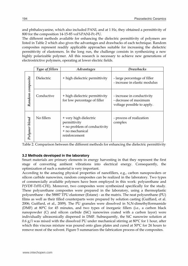
and phthalocyanine, which also included PANI, and at 1 Hz, they obtained a permittivity of 800 for the composition 14-15-85 vol%PANI-Pc-PU. The different methods available for enhancing the dielectric permittivity of polymers are listed in Table 2 which also gives the advantages and drawbacks of each technique. Random composites represent readily applicable approaches suitable for increasing the dielectric permittivity of elastomers. In the long run, the challenge consists in synthesizing a new highly polarizable polymer. All this research is necessary to achieve new generations of electrostrictive polymers, operating at lower electric fields.
Type of fillers Advantages Drawbacks
Ran
dom
com
posi
te
Dielectric + high dielectric permittivity
- large percentage of filler - increase in elastic modulus
Conductive
+ high dielectric permittivity for low percentage of filler
- increase in conductivity - decrease of maximum voltage possible to apply.
Poly
mer
ble
nd
No fillers + very high dielectric permittivity + no problem of conductivity + no mechanical reinforcement
- process of realization complex
Table 2. Comparison between the different methods for enhancing the dielectric permittivity
3.2 Methods developed in the laboratory Smart materials are primary elements in energy harvesting in that they represent the first stage of converting ambient vibrations into electrical energy. Consequently, the optimization of such a material is very important. According to the amazing physical properties of nanofillers, e.g., carbon nanopowders or silicon carbide nanowires, random composites can be realized in the laboratory. Two types of commercially available polymers have been employed in this work: polyurethane and P(VDF-TrFE-CFE). Moreover, two composites were synthesized specifically for the study. These polyurethane composites were prepared in the laboratory, using a thermoplastic polyurethane - the 58887 TPU elastomer (Estane) - as the matrix. The neat polyurethane (PU) films as well as their filled counterparts were prepared by solution casting (Guiffard, et al. 2006; Guiffard, et al., 2009). The PU granules were dissolved in N,N-dimethylformamide (DMF) at 80°C for 45 minutes, and two types of inorganic fillers (i.e., a carbon black nanopowder (C) and silicon carbide (SiC) nanowires coated with a carbon layer) were individually ultrasonically dispersed in DMF. Subsequently, the SiC nanowire solution at 0.6 g/l was mixed with the dissolved PU under mechanical stirring at 80°C for 1 hour, after which this viscous mixture was poured onto glass plates and cured at 50°C for 24 hours to remove most of the solvent. Figure 5 summarizes the fabrication process of the composites.
Fig. 5. Principle of realization of the polymer composite
3.3 Characteristics of the composites The microstructure of the composites was investigated by scanning electron microscopy (SEM) on samples fractured in liquid nitrogen and sputtered with a thin gold layer prior to the SEM observations. The degree of filler dispersion in the polymer matrix and the binding between the nanocharges and the matrix determined the properties of the composite materials. SEM images of the fracture surfaces of the composites are presented in Fig. 6. Figures 6.a and 6.b respectively depict the dispersion of a carbon black nanopowder and SiC nanowires within the PU matrix. Both filler types were found to be well dispersed in the matrix which was in good agreement with the nonconduction state observed in the composites.
Fig. 6. (Left to right) Morphology of fractured surfaces of the composites filled with (a) a carbon black nanopowder fillers and (b) SiC nanowires.
In order to evaluate the contribution of space charge, the dielectric constant of the composites loaded with fillers was measured using an HP 4284A LCR meter over a broad range of frequencies (from 0.01 Hz to 1 MHz) at room temperature. Figure 7 shows the
www.intechopen.com

Electrostrictive polymers as high-performance electroactive polymers for energy harvesting 195
and phthalocyanine, which also included PANI, and at 1 Hz, they obtained a permittivity of 800 for the composition 14-15-85 vol%PANI-Pc-PU. The different methods available for enhancing the dielectric permittivity of polymers are listed in Table 2 which also gives the advantages and drawbacks of each technique. Random composites represent readily applicable approaches suitable for increasing the dielectric permittivity of elastomers. In the long run, the challenge consists in synthesizing a new highly polarizable polymer. All this research is necessary to achieve new generations of electrostrictive polymers, operating at lower electric fields.
Type of fillers Advantages Drawbacks
Ran
dom
com
posi
te
Dielectric + high dielectric permittivity
- large percentage of filler - increase in elastic modulus
Conductive
+ high dielectric permittivity for low percentage of filler
- increase in conductivity - decrease of maximum voltage possible to apply.
Poly
mer
ble
nd
No fillers + very high dielectric permittivity + no problem of conductivity + no mechanical reinforcement
- process of realization complex
Table 2. Comparison between the different methods for enhancing the dielectric permittivity
3.2 Methods developed in the laboratory Smart materials are primary elements in energy harvesting in that they represent the first stage of converting ambient vibrations into electrical energy. Consequently, the optimization of such a material is very important. According to the amazing physical properties of nanofillers, e.g., carbon nanopowders or silicon carbide nanowires, random composites can be realized in the laboratory. Two types of commercially available polymers have been employed in this work: polyurethane and P(VDF-TrFE-CFE). Moreover, two composites were synthesized specifically for the study. These polyurethane composites were prepared in the laboratory, using a thermoplastic polyurethane - the 58887 TPU elastomer (Estane) - as the matrix. The neat polyurethane (PU) films as well as their filled counterparts were prepared by solution casting (Guiffard, et al. 2006; Guiffard, et al., 2009). The PU granules were dissolved in N,N-dimethylformamide (DMF) at 80°C for 45 minutes, and two types of inorganic fillers (i.e., a carbon black nanopowder (C) and silicon carbide (SiC) nanowires coated with a carbon layer) were individually ultrasonically dispersed in DMF. Subsequently, the SiC nanowire solution at 0.6 g/l was mixed with the dissolved PU under mechanical stirring at 80°C for 1 hour, after which this viscous mixture was poured onto glass plates and cured at 50°C for 24 hours to remove most of the solvent. Figure 5 summarizes the fabrication process of the composites.
Fig. 5. Principle of realization of the polymer composite
3.3 Characteristics of the composites The microstructure of the composites was investigated by scanning electron microscopy (SEM) on samples fractured in liquid nitrogen and sputtered with a thin gold layer prior to the SEM observations. The degree of filler dispersion in the polymer matrix and the binding between the nanocharges and the matrix determined the properties of the composite materials. SEM images of the fracture surfaces of the composites are presented in Fig. 6. Figures 6.a and 6.b respectively depict the dispersion of a carbon black nanopowder and SiC nanowires within the PU matrix. Both filler types were found to be well dispersed in the matrix which was in good agreement with the nonconduction state observed in the composites.
Fig. 6. (Left to right) Morphology of fractured surfaces of the composites filled with (a) a carbon black nanopowder fillers and (b) SiC nanowires.
In order to evaluate the contribution of space charge, the dielectric constant of the composites loaded with fillers was measured using an HP 4284A LCR meter over a broad range of frequencies (from 0.01 Hz to 1 MHz) at room temperature. Figure 7 shows the
www.intechopen.com

Piezoelectric Ceramics196
variation in dielectric constants for a pure PU material and filled composites versus frequency. A large decrease in the dielectric constant was observed at around 1 Hz for both composites when the frequency increased. Such a behavior is known to be due to the loss of one of the polarization contributions (interfacial polarization, orientation polarization, electronic polarization, atomic polarization, etc) of the dielectric constant value (Mitchell, 2004). Considering the value of the frequency, this decrease can be unambiguously attributed to the loss of the space-charge-induced interfacial polarization contribution. It can moreover been seen that the contribution of the space charge can be neglected for frequencies below 5 Hz. As further shown in Fig. 7, the dielectric constant of the C-filled and SiC-filled nanocomposites was consistently higher than that of the pure PU composite. As expected, at higher frequencies, the gap between the values of the dielectric constant for pure PU as opposed to for the nanocomposites was not very high, which confirmed the fact that the filler content was low in comparison to the threshold value. Moreover, the space charge mechanism did not contribute to the dielectric constant. The incorporation of conductive charges probably also increased the space charge density in addition to intrinsically induced by the existence of soft and hard segments within the matrix. Similar observations have been reported by Dang et al., (Dang, et al., 2002), who assumed an additional contribution to the quantity of accumulated charge when fillers were used. As previously reported, (Nurazreena, et al. 2006) the percolation threshold depends not only on the size, shape, and spatial distribution of the fillers within the polymeric matrix but also on the processing. It is clear that the percolation threshold must be different when employing SiC nanowires as opposed to a carbon black powder as fillers. This remark can explain the slight difference observed between the permittivity of the two composite types in addition to the fact that the two fillers had not been incorporated in equal content.
100
102
104
106
0
2
4
6
8
10
12
14
16
frequency (Hz)
diel
ectr
ic p
erm
ittiv
ity
PU purPU 1vt%CPU 0.5wt%SiC
Fig. 7. The variation in the dielectric constant for a pure PU material and filled composite vs frequency.
4. Energy harvester characterization
This section describes the setup developed for characterizing the harvested power. It also includes a discussion of the obtained results and a comparison to the model mentioned in section 2.2.
4.1 Principle of measurement of the harvested power Figure 8 provides a schematic representation of the setup developed for characterizing the power harvested by the polymer film. The mechanical system consisted of a shaker and a capacitive sensor. The shaker produced a vibration force in sinusoidal form, causing the sample to undergo a transverse vibration. The capacitive sensor (Fogale MC 940) recorded the transverse displacement of the sample from which the strain S1 was calculated. The electrostrictive polymer was subjected to a DC biased electric field, produced by a function generator and amplified by a high-voltage power amplifier (Trek Model 10/10). As the polymer was not piezoelectric, it was necessary to induce a polarization with a DC bias in order to obtain a pseudo-piezoelectric behavior. The electroactive polymer was excited both electrically and mechanically, in order for its expansion and contraction to induce a current measured by the current amplifier (Keithley 617), thus giving rise to “an image” of the power harvesting by the polymer, due to electrical resistance (Rc). In this setup, the current was chosen as it is known to be less sensitive to the noise from the electrical network (50 Hz) and in order to avoid problems of impedance adaptation. All the data was monitored by an oscilloscope (Agilent DS0 6054A Mega zoom).
Fig. 8. A schematic of the experimental setup for the energy harvesting measurements. A purely resistive load was directly connected to the electrostrictive element (Fig.8). In this case, the voltage on the load Rc was alternating. Considering equation (10) and the resistance of the load, the dynamic voltage on the electrostrictive element can be expressed in the frequency domain as a function of the displacement, the angular frequency ω.
www.intechopen.com

Electrostrictive polymers as high-performance electroactive polymers for energy harvesting 197
variation in dielectric constants for a pure PU material and filled composites versus frequency. A large decrease in the dielectric constant was observed at around 1 Hz for both composites when the frequency increased. Such a behavior is known to be due to the loss of one of the polarization contributions (interfacial polarization, orientation polarization, electronic polarization, atomic polarization, etc) of the dielectric constant value (Mitchell, 2004). Considering the value of the frequency, this decrease can be unambiguously attributed to the loss of the space-charge-induced interfacial polarization contribution. It can moreover been seen that the contribution of the space charge can be neglected for frequencies below 5 Hz. As further shown in Fig. 7, the dielectric constant of the C-filled and SiC-filled nanocomposites was consistently higher than that of the pure PU composite. As expected, at higher frequencies, the gap between the values of the dielectric constant for pure PU as opposed to for the nanocomposites was not very high, which confirmed the fact that the filler content was low in comparison to the threshold value. Moreover, the space charge mechanism did not contribute to the dielectric constant. The incorporation of conductive charges probably also increased the space charge density in addition to intrinsically induced by the existence of soft and hard segments within the matrix. Similar observations have been reported by Dang et al., (Dang, et al., 2002), who assumed an additional contribution to the quantity of accumulated charge when fillers were used. As previously reported, (Nurazreena, et al. 2006) the percolation threshold depends not only on the size, shape, and spatial distribution of the fillers within the polymeric matrix but also on the processing. It is clear that the percolation threshold must be different when employing SiC nanowires as opposed to a carbon black powder as fillers. This remark can explain the slight difference observed between the permittivity of the two composite types in addition to the fact that the two fillers had not been incorporated in equal content.
100
102
104
106
0
2
4
6
8
10
12
14
16
frequency (Hz)
diel
ectr
ic p
erm
ittiv
ity
PU purPU 1vt%CPU 0.5wt%SiC
Fig. 7. The variation in the dielectric constant for a pure PU material and filled composite vs frequency.
4. Energy harvester characterization
This section describes the setup developed for characterizing the harvested power. It also includes a discussion of the obtained results and a comparison to the model mentioned in section 2.2.
4.1 Principle of measurement of the harvested power Figure 8 provides a schematic representation of the setup developed for characterizing the power harvested by the polymer film. The mechanical system consisted of a shaker and a capacitive sensor. The shaker produced a vibration force in sinusoidal form, causing the sample to undergo a transverse vibration. The capacitive sensor (Fogale MC 940) recorded the transverse displacement of the sample from which the strain S1 was calculated. The electrostrictive polymer was subjected to a DC biased electric field, produced by a function generator and amplified by a high-voltage power amplifier (Trek Model 10/10). As the polymer was not piezoelectric, it was necessary to induce a polarization with a DC bias in order to obtain a pseudo-piezoelectric behavior. The electroactive polymer was excited both electrically and mechanically, in order for its expansion and contraction to induce a current measured by the current amplifier (Keithley 617), thus giving rise to “an image” of the power harvesting by the polymer, due to electrical resistance (Rc). In this setup, the current was chosen as it is known to be less sensitive to the noise from the electrical network (50 Hz) and in order to avoid problems of impedance adaptation. All the data was monitored by an oscilloscope (Agilent DS0 6054A Mega zoom).
Fig. 8. A schematic of the experimental setup for the energy harvesting measurements. A purely resistive load was directly connected to the electrostrictive element (Fig.8). In this case, the voltage on the load Rc was alternating. Considering equation (10) and the resistance of the load, the dynamic voltage on the electrostrictive element can be expressed in the frequency domain as a function of the displacement, the angular frequency ω.
www.intechopen.com

Piezoelectric Ceramics198
~ ~..
1 . .dc c
c p
E RV j u
jR C (12)
Starting from equation (12), the harvested power can be written as a function of the displacement amplitude um:
~ ~ 2* 2 2
_ 2
.. .2. 21 . .
dc cm m mharvested AC
c c p
E RV V uPR R C
(13)
with Vm as the maximum voltage. The harvested power reaches a maximum Pharvested_AC_max for an optimal load Ropt_AC, and the optimal load resistance can be calculated according to :
2
2 2 2_
22
1 . . . ..21 . .
c pharvested AC dc m
cc p
R CP E uR R C
(14)
_ 0harvested AC
c
PR
when 22
2
.1pC C
R and thus the power is at maximum for
ACoptp
c RC
R _.1 (15)
Consequently, for the matched load the maximum power harvested is equal to 2 2
_ _max
. .4.dc m
harvested ACp
E uP
C (16)
4.2 Validation of the model Preliminary measurements for the determination of the theoretical results of the harvested power have also been performed to evaluate the values of 31 02. . . .dc dcE M Y A E L .
Current measurements under short circuit conditions have been carried out for the former, as the short-circuit current magnitude I0 is given by equation (7). Assuming a uniform strain in the material, the short-circuit current can be expressed as:
1310 ......2 SEYAMI dc (17)
The short-circuit current was performed at 100 Hz for a constant strain of 0.5% and for different electric fields (Fig. 11). As expected, a linear relation between the current and the electric field was observed, and a previous study demonstrated the validation of this model (Lebrun, et al. 2009). The choice of the frequency is not trivial, since most potential vibration sources have their fundamental vibration mode bellow 200 Hz, as demonstrated by Roundy et al. (Roundy, et al., 2003), and summarized in Table 3.
Vibration source Fundamental frequency vibration (Hz)
Clothes dryer 121
Windows next to a busy road 100
People walking 1 Table 3. Vibration sources and their fundamental vibration mode
0 2 4 6 8 100
2
4
6
8
10
12
static electric field (V/µm)
I 0 (µA
)
experimental datalinear fit
Fig. 9. The short-circuit current versus the static electric field for a constant strain of 0.5% at 100 Hz for P(VDF-TrFE-CFE).
In order to access the validity of the model of the harvested power presented in section 2.2 (eqs. (12) and (22)), various measurements were carried out. Figures 10 presents the power versus the electric field, for a constant electric load and strain (S1=0.25%), as well as the power harvested as a function of the strain for a constant electric field (Edc=5V/µm), with the same electric load (Rc=500kΩ). As expected from the model, a quadratic dependence between the power and the static electric field strain was observed. The experimental results thus validated the developed model for evaluating the harvested power. To assess the validity of the model, various measurements were carried out. Figure 11 presents the power versus electric load for a given electric field (5 V/µm) and strain (0.2%) at 100 Hz. This data pointed out the existence of an optimal load resistance, as theoretically expected according to equation (15)
www.intechopen.com

Electrostrictive polymers as high-performance electroactive polymers for energy harvesting 199
~ ~..
1 . .dc c
c p
E RV j u
jR C (12)
Starting from equation (12), the harvested power can be written as a function of the displacement amplitude um:
~ ~ 2* 2 2
_ 2
.. .2. 21 . .
dc cm m mharvested AC
c c p
E RV V uPR R C
(13)
with Vm as the maximum voltage. The harvested power reaches a maximum Pharvested_AC_max for an optimal load Ropt_AC, and the optimal load resistance can be calculated according to :
2
2 2 2_
22
1 . . . ..21 . .
c pharvested AC dc m
cc p
R CP E uR R C
(14)
_ 0harvested AC
c
PR
when 22
2
.1pC C
R and thus the power is at maximum for
ACoptp
c RC
R _.1 (15)
Consequently, for the matched load the maximum power harvested is equal to 2 2
_ _max
. .4.dc m
harvested ACp
E uP
C (16)
4.2 Validation of the model Preliminary measurements for the determination of the theoretical results of the harvested power have also been performed to evaluate the values of 31 02. . . .dc dcE M Y A E L .
Current measurements under short circuit conditions have been carried out for the former, as the short-circuit current magnitude I0 is given by equation (7). Assuming a uniform strain in the material, the short-circuit current can be expressed as:
1310 ......2 SEYAMI dc (17)
The short-circuit current was performed at 100 Hz for a constant strain of 0.5% and for different electric fields (Fig. 11). As expected, a linear relation between the current and the electric field was observed, and a previous study demonstrated the validation of this model (Lebrun, et al. 2009). The choice of the frequency is not trivial, since most potential vibration sources have their fundamental vibration mode bellow 200 Hz, as demonstrated by Roundy et al. (Roundy, et al., 2003), and summarized in Table 3.
Vibration source Fundamental frequency vibration (Hz)
Clothes dryer 121
Windows next to a busy road 100
People walking 1 Table 3. Vibration sources and their fundamental vibration mode
0 2 4 6 8 100
2
4
6
8
10
12
static electric field (V/µm)
I 0 (µA
)
experimental datalinear fit
Fig. 9. The short-circuit current versus the static electric field for a constant strain of 0.5% at 100 Hz for P(VDF-TrFE-CFE).
In order to access the validity of the model of the harvested power presented in section 2.2 (eqs. (12) and (22)), various measurements were carried out. Figures 10 presents the power versus the electric field, for a constant electric load and strain (S1=0.25%), as well as the power harvested as a function of the strain for a constant electric field (Edc=5V/µm), with the same electric load (Rc=500kΩ). As expected from the model, a quadratic dependence between the power and the static electric field strain was observed. The experimental results thus validated the developed model for evaluating the harvested power. To assess the validity of the model, various measurements were carried out. Figure 11 presents the power versus electric load for a given electric field (5 V/µm) and strain (0.2%) at 100 Hz. This data pointed out the existence of an optimal load resistance, as theoretically expected according to equation (15)
www.intechopen.com

Piezoelectric Ceramics200
0 0.2 0.4 0.6 0.80
5
10
15
20
25
30
35
transverse strain (%)
pow
er (
µW
)
experimentalmodel
0 2 4 6 8 100
2
4
6
8
10
12
static electric field (V/µm)
pow
er (
µW
)
experimentalmodel
Fig. 10. (Left to right) The harvested power as a function of the static electric field, for a constant strain of S1=0.2%, and the harvested power versus the transverse strain for a biased field of 5 V/µm, in both cases for a P(VDF-TrFE-CFE) at 100 Hz and Rc=500 kΩ.
0 1 2 3 4 5
x 106
0
0.5
1
1.5
2
2.5
R (ohm)
Pow
er
(µW
)
modelexperimental
Fig. 11. The harvested power in AC for a constant electric field of 5 V/µm and a strain of 0.2% at 100 Hz.
4.3 Harvested power versus polymer Table 4 gives the harvested power density for the polymer and composites at Edc=5 V/µm, S1=0.25% and 100 Hz, for their matched load. The power density for the polymer and composites was very low. Although this could be considered a disappointing result, one should keep in mind that in the electrostrictive case, the power was proportional to the square of the bias field (eq. 16), evaluated in Table 4 for a relatively low bias value. For example, doubling the value of the bias field to 10 V/µm (which is still quite low) would result in a power that was four times larger. The output power of the composites with C nanofillers, SiC fillers, and pure PU under the conditions given below was estimated to be 1, 0.41, and 0.25 µW/cm3, respectively. The ratio between the estimated harvested power for the pure PU film and the nanofilled composites was equal to 3 in the case of C nanofillers and 1.4 for SiC fillers. This ratio was almost identical to the ratio of the square of the film permittivity, which was in good agreement with the fact that M31 is practically proportional to ε0(εr-1)²/(Y. εr) and with the expression of power harvesting according to equation (16). Obviously, the PU loaded with 1%C exhibited the highest dielectric permittivity and power density in the case of PU. However, with pure PU and for the same power density, an electric field of 10 V/µm was necessary, which was two times as high as for PU 1vl%C. The way of introducing the conductive particles into the polymer matrix was very interesting since it was possible to create a material capable of harvesting power under low electric fields. The highest power density of 180 µW/cm3 was obtained with the terpolymer matrix of P(VDF-TrFE-CFE). This seemed to be a very promising material, especially if nanoparticles were induced in the matrix.
Type εr Y (MPa) Power harvested (µW/cm3 )
Pure PU 4.8 40 0.25
PU 0.5%SiC 5.6 70 0.41
PU 1%C 8.4 40 1.0
P(VDF-TrFE-CFE) 42 500 180
Table 4. Material characteristics and harvested power density at 100 Hz for a static electric field of 5 V/µm and a transverse strain of 0.2%.
Nevertheless, the dielectric permittivity is not the only parameter to vary when attempting to optimize the harvested power; it depends on the application. For example, if a large strain of more than 100% is available, e.g., during human walking, a polymer able to support such a large strain before plastic transition is necessary. An example of such a material is PU, since it can be stretched up to 400%. This can be compared to the maximum for a P(VDF-TrFE-CFE), which is only 40%. Two techniques exist for harvesting energy when utilizing electrostrictive polymers. The first was proposed by Ren et al. (Ren, et al., 2007) and consists of creating an energetic cycle, whereas the second involves applying a bias voltage for working in the pseudo piezoelectric behavior. Table 5 presents a comparison between the two methods. The energy harvesting based on the pseudo-piezolectric behavior was lower than the cycle-based energy harvesting. Although this could be considered a disappointing result, one should keep in
www.intechopen.com

Electrostrictive polymers as high-performance electroactive polymers for energy harvesting 201
0 0.2 0.4 0.6 0.80
5
10
15
20
25
30
35
transverse strain (%)
pow
er (
µW
)
experimentalmodel
0 2 4 6 8 100
2
4
6
8
10
12
static electric field (V/µm)
pow
er (
µW
)
experimentalmodel
Fig. 10. (Left to right) The harvested power as a function of the static electric field, for a constant strain of S1=0.2%, and the harvested power versus the transverse strain for a biased field of 5 V/µm, in both cases for a P(VDF-TrFE-CFE) at 100 Hz and Rc=500 kΩ.
0 1 2 3 4 5
x 106
0
0.5
1
1.5
2
2.5
R (ohm)
Pow
er
(µW
)
modelexperimental
Fig. 11. The harvested power in AC for a constant electric field of 5 V/µm and a strain of 0.2% at 100 Hz.
4.3 Harvested power versus polymer Table 4 gives the harvested power density for the polymer and composites at Edc=5 V/µm, S1=0.25% and 100 Hz, for their matched load. The power density for the polymer and composites was very low. Although this could be considered a disappointing result, one should keep in mind that in the electrostrictive case, the power was proportional to the square of the bias field (eq. 16), evaluated in Table 4 for a relatively low bias value. For example, doubling the value of the bias field to 10 V/µm (which is still quite low) would result in a power that was four times larger. The output power of the composites with C nanofillers, SiC fillers, and pure PU under the conditions given below was estimated to be 1, 0.41, and 0.25 µW/cm3, respectively. The ratio between the estimated harvested power for the pure PU film and the nanofilled composites was equal to 3 in the case of C nanofillers and 1.4 for SiC fillers. This ratio was almost identical to the ratio of the square of the film permittivity, which was in good agreement with the fact that M31 is practically proportional to ε0(εr-1)²/(Y. εr) and with the expression of power harvesting according to equation (16). Obviously, the PU loaded with 1%C exhibited the highest dielectric permittivity and power density in the case of PU. However, with pure PU and for the same power density, an electric field of 10 V/µm was necessary, which was two times as high as for PU 1vl%C. The way of introducing the conductive particles into the polymer matrix was very interesting since it was possible to create a material capable of harvesting power under low electric fields. The highest power density of 180 µW/cm3 was obtained with the terpolymer matrix of P(VDF-TrFE-CFE). This seemed to be a very promising material, especially if nanoparticles were induced in the matrix.
Type εr Y (MPa) Power harvested (µW/cm3 )
Pure PU 4.8 40 0.25
PU 0.5%SiC 5.6 70 0.41
PU 1%C 8.4 40 1.0
P(VDF-TrFE-CFE) 42 500 180
Table 4. Material characteristics and harvested power density at 100 Hz for a static electric field of 5 V/µm and a transverse strain of 0.2%.
Nevertheless, the dielectric permittivity is not the only parameter to vary when attempting to optimize the harvested power; it depends on the application. For example, if a large strain of more than 100% is available, e.g., during human walking, a polymer able to support such a large strain before plastic transition is necessary. An example of such a material is PU, since it can be stretched up to 400%. This can be compared to the maximum for a P(VDF-TrFE-CFE), which is only 40%. Two techniques exist for harvesting energy when utilizing electrostrictive polymers. The first was proposed by Ren et al. (Ren, et al., 2007) and consists of creating an energetic cycle, whereas the second involves applying a bias voltage for working in the pseudo piezoelectric behavior. Table 5 presents a comparison between the two methods. The energy harvesting based on the pseudo-piezolectric behavior was lower than the cycle-based energy harvesting. Although this could be considered a disappointing result, one should keep in
www.intechopen.com
Piezoelectric Ceramics202
mind that the strain in our case was ten times lower and the electric field was fourteen times lower. The model demonstrates that the energy harvesting was proportional to the square of these two conditions (strain and electric field), so for the same configuration, the energy density was 30 mJ/cm3 for a system working in the pseudo piezoelectric state. This density was approximately the same as in the case of Ren et al. The great advantage of our method for mechanical energy harvesting consists in this technique requiring only a static field for its operation. The technique is consequently very simple to realize and implement, using for example batteries, or for an autonomous system, employing a piezoelectric material to produce the bias voltage.
Method Material S1 (%) E3 (V/µm) Energy harvesting (J/cm3) pseudo-
piezoelectric P(VDF-TrFE-CFE) 0.2 5 1.8. 10-6
cycle P(VDF-TrFE)
[Ren 2007] 2 67 22.4.10-3 Table 5. Comparison between two methods for harvesting energy.
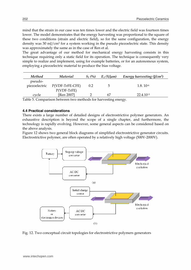
4.4 Practical considerations There exists a large number of detailed designs of electrostrictive polymer generators. An exhaustive description is beyond the scope of a single chapter, and furthermore, the technology is rapidly evolving. However, some general aspects can be considered based on the above analysis. Figure 12 shows two general block diagrams of simplified electrostrictive generator circuits. Electrostrictive polymer, are often operated by a relatively high voltage (500V-2000V).
Fig. 12. Two conceptual circuit topologies for electrostrictive polymers generators
Portable applications are powered with lower voltages compatible with battery power. Moreover, in order to generate the bias voltage required for working in the pseudo-piezoelectric behavior, a step-up voltage converter has to be part of the generator circuit as in Fig. 12. Typically, they use high-speed switching with inductors or transformers, though other methods such as piezoelectric converters are also known. One such option is to use rechargeable low-voltage batteries for applying the bias electric field, as shown in Fig. 12 (a). However, a possible drawback of this design is that the static electric field must be raised in voltage relative to that of the battery. A step-up converter is needed in this case, which leads to increased costs. The important issue in this case is however not so much the added cost but the additional power loss from the conversion. Note that in configuration (b), only the generated energy has to be converted. The bias voltage was provided by means of other materials, like piezoelectric ceramics, which rendered it possible to create an autonomous system without batteries. Electrostrictive polymer leakage is another practical consideration in power generation. Such leakage is a direct loss to the system. The importance of leakage phenomena depends very much on both the electrostrictive resistivity and the frequency operation. Leakage losses may influence the choice of polymer, but good dielectric materials can generally be identified to address this issue for most applications. For example, PU has such an outstanding resistivity that leakage losses may be insignificant (Cottinet, et al. 2010). The biggest advantage of electrostrictive polymers might be the point that, in addition to a good dynamic range, they operate best at relatively long strokes and modest forces. This is a difficult part of the design space to address using conventional smart materials such as piezoelectrics ceramics. Moreover, it is a very common mechanical input available from a number of sources in the environment, such as human motion and wave power.
5. Applications of electrostrictive polymers for energy harvesting
Virtually any application where there is a need of electrical energy is a potential application for electrostrictive polymer generators. Figure 13, presents the orders of magnitude of the powers consumed by various CMOS electronic equipment that could be powered by miniature energy harvesting devices. This data shows the potential applications of electrostrictive polymers for energy harvesting. The harvested power density reported in this paper would be enough to power complex devices such as watches or RFID tags. However, this material is much more competitive for certain applications as opposed to others, and it is important for a new technology to identify general and specific areas of application where it can be the most competitive. A general advantage and drawback of the various classes of EAPs for energy harvesting are summarized in Table 6. All the materials exhibit a high energy harvesting density, except for the ionic polymer. Nevertheless, the main advantage of this material is that it does not require any other polarization tension in order to operate. It is thus possible to realize autonomous systems without batteries. The difference in energy harvesting between dielectric elastomers and electrostrictive polymers is not very large. The great advantage of dielectric elastomers is the possibility of having high strains of more than 400% as compared to electrostrictive polymers (100%). However, the former materials require higher electric fields, causing the size of the device to increase, in addition to the loss due to the conversion of the high voltage.
www.intechopen.com
Electrostrictive polymers as high-performance electroactive polymers for energy harvesting 203
mind that the strain in our case was ten times lower and the electric field was fourteen times lower. The model demonstrates that the energy harvesting was proportional to the square of these two conditions (strain and electric field), so for the same configuration, the energy density was 30 mJ/cm3 for a system working in the pseudo piezoelectric state. This density was approximately the same as in the case of Ren et al. The great advantage of our method for mechanical energy harvesting consists in this technique requiring only a static field for its operation. The technique is consequently very simple to realize and implement, using for example batteries, or for an autonomous system, employing a piezoelectric material to produce the bias voltage.
Method Material S1 (%) E3 (V/µm) Energy harvesting (J/cm3) pseudo-
piezoelectric P(VDF-TrFE-CFE) 0.2 5 1.8. 10-6
cycle P(VDF-TrFE)
[Ren 2007] 2 67 22.4.10-3 Table 5. Comparison between two methods for harvesting energy.
4.4 Practical considerations There exists a large number of detailed designs of electrostrictive polymer generators. An exhaustive description is beyond the scope of a single chapter, and furthermore, the technology is rapidly evolving. However, some general aspects can be considered based on the above analysis. Figure 12 shows two general block diagrams of simplified electrostrictive generator circuits. Electrostrictive polymer, are often operated by a relatively high voltage (500V-2000V).
Fig. 12. Two conceptual circuit topologies for electrostrictive polymers generators
Portable applications are powered with lower voltages compatible with battery power. Moreover, in order to generate the bias voltage required for working in the pseudo-piezoelectric behavior, a step-up voltage converter has to be part of the generator circuit as in Fig. 12. Typically, they use high-speed switching with inductors or transformers, though other methods such as piezoelectric converters are also known. One such option is to use rechargeable low-voltage batteries for applying the bias electric field, as shown in Fig. 12 (a). However, a possible drawback of this design is that the static electric field must be raised in voltage relative to that of the battery. A step-up converter is needed in this case, which leads to increased costs. The important issue in this case is however not so much the added cost but the additional power loss from the conversion. Note that in configuration (b), only the generated energy has to be converted. The bias voltage was provided by means of other materials, like piezoelectric ceramics, which rendered it possible to create an autonomous system without batteries. Electrostrictive polymer leakage is another practical consideration in power generation. Such leakage is a direct loss to the system. The importance of leakage phenomena depends very much on both the electrostrictive resistivity and the frequency operation. Leakage losses may influence the choice of polymer, but good dielectric materials can generally be identified to address this issue for most applications. For example, PU has such an outstanding resistivity that leakage losses may be insignificant (Cottinet, et al. 2010). The biggest advantage of electrostrictive polymers might be the point that, in addition to a good dynamic range, they operate best at relatively long strokes and modest forces. This is a difficult part of the design space to address using conventional smart materials such as piezoelectrics ceramics. Moreover, it is a very common mechanical input available from a number of sources in the environment, such as human motion and wave power.
5. Applications of electrostrictive polymers for energy harvesting
Virtually any application where there is a need of electrical energy is a potential application for electrostrictive polymer generators. Figure 13, presents the orders of magnitude of the powers consumed by various CMOS electronic equipment that could be powered by miniature energy harvesting devices. This data shows the potential applications of electrostrictive polymers for energy harvesting. The harvested power density reported in this paper would be enough to power complex devices such as watches or RFID tags. However, this material is much more competitive for certain applications as opposed to others, and it is important for a new technology to identify general and specific areas of application where it can be the most competitive. A general advantage and drawback of the various classes of EAPs for energy harvesting are summarized in Table 6. All the materials exhibit a high energy harvesting density, except for the ionic polymer. Nevertheless, the main advantage of this material is that it does not require any other polarization tension in order to operate. It is thus possible to realize autonomous systems without batteries. The difference in energy harvesting between dielectric elastomers and electrostrictive polymers is not very large. The great advantage of dielectric elastomers is the possibility of having high strains of more than 400% as compared to electrostrictive polymers (100%). However, the former materials require higher electric fields, causing the size of the device to increase, in addition to the loss due to the conversion of the high voltage.
www.intechopen.com
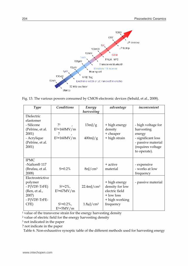
Piezoelectric Ceramics204
Fig. 13. The various powers consumed by CMOS electronic devices (Sebald, et al., 2008).
Type Conditions Energy harvesting
advantage inconvenient
Dielectric elastomer - Silicone (Pelrine, et al. 2001) - Acrylique (Pelrine, et al. 2001)
?3 , E2=160MV/m
? , E2=160MV/m
13mJ/g
400mJ/g
+ high energy density + cheaper + high strain
- high voltage for harvesting energy - significant loss - passive material (requires voltage to operate).
IPMC -Nafion® 117 (Brufau, et al. 2008)
S=0.2%
8nJ/cm3
+ active material
- expensive - works at low frequency
Electrostrictive polymer - P(VDF-TrFE) (Ren, et al., 2007) - P(VDF-TrFE-CFE)
S1=2%, E2=67MV/m
S1=0.2%, E2=5MV/m
22.4mJ/cm3
1.8µJ/cm3
+ high energy density for low electric field + low loss + high working frequency
- passive material
1 value of the transverse strain for the energy harvesting density 2 value of electric field for the energy harvesting density 3 not indicated in the paper ? not indicate in the paper Table 6. Non-exhaustive synoptic table of the different methods used for harvesting energy
Compared to piezoelectric generators, electrostrictive polymers may offer advantages such as lower cost, lighter weight, or smaller size. These materials are well suited for harvesting energy from human motion. Natural muscle, the driving force for human motion, typically works at low frequencies and is intrinsically linear; two characteristics where electrostrictive polymers offer advantages. They are also interesting for wave motions with relatively low frequencies of 0.1 Hz to 1 Hz, and high amplitudes (wave heights on the order of 1 m are common). Many other interesting applications exist for electrostrictive polymer. Remote and/or wireless devices are growing in use; an ideal devices can harvest their own energy thereby eliminating the need for battery replacement. Electrostrictive polymers are well suited for these applications if mechanical energy is available, as might be the case in portable devices carried by people, animals, or automobiles. Moreover, it is possible to deposit such materials on large surface, which is very interesting for health monitoring in the wings of airplanes, for example. In summary, the major advantages of this technology include the lighter weight, greater simplicity, and lower cost.
6. Conclusions
Electrostrictive polymer composites for energy harvesting have been developed and tested using different types of polymers. A good agreement between the modeled data and actual results was found. Various means of increasing the intrinsic characteristics of the polymers was also studied A comparison between the different techniques for harvesting energy has been realized, and demonstrated the simplicity and advantage of working in the pseudo-piezoelectric behavior. Future work will concern the research of polymer matrices and novel fillers to increase the permittivity of the resultant composites and consequently their capabilities of harvesting electrical energy upon mechanical vibrations. As an example can be mentioned P(VDF-TrFE-CFE) filled with carbon particles. Another point of research within this topic will concern an optimization of electrical boundary conditions on our harvester by using a non-linear technique. The present chapter demonstrates the potential for future application. In fact, one of the most important trends in the electronic equipment technology from its origins has been the reduction in size and the increase in functionality. Nowadays, small, handheld, though very powerful, devices are commercially available. They allow the user to play music, to wirelessly communicate or to compute practically everywhere. The size of such devices is becoming so small that the term wearable device is being used instead of portable device; they can be integrated in everyday objects such as watches, glasses, clothes, etc. Electrostrictive polymers have demonstrated excellent performances. Numerous applications appear feasible, but challenges remain. Electrostrictive polymers seem to be more advantageous for applications requiring low or variable frequencies, low cost, and large areas. Currently, piezoelectric (PZT) materials are the most popular options for harvesting mechanical energy because of their compact configuration and compatibility with Micro-Electro-Mechanical Systems (MEMS). However, their inherent limitations include aging, depolarization, and brittleness. Finding ways to circumvent these limitations is the next exciting and puzzling challenge to achieve realistic EAP energy harvesters.
www.intechopen.com

Electrostrictive polymers as high-performance electroactive polymers for energy harvesting 205
Fig. 13. The various powers consumed by CMOS electronic devices (Sebald, et al., 2008).
Type Conditions Energy harvesting
advantage inconvenient
Dielectric elastomer - Silicone (Pelrine, et al. 2001) - Acrylique (Pelrine, et al. 2001)
?3 , E2=160MV/m
? , E2=160MV/m
13mJ/g
400mJ/g
+ high energy density + cheaper + high strain
- high voltage for harvesting energy - significant loss - passive material (requires voltage to operate).
IPMC -Nafion® 117 (Brufau, et al. 2008)
S=0.2%
8nJ/cm3
+ active material
- expensive - works at low frequency
Electrostrictive polymer - P(VDF-TrFE) (Ren, et al., 2007) - P(VDF-TrFE-CFE)
S1=2%, E2=67MV/m
S1=0.2%, E2=5MV/m
22.4mJ/cm3
1.8µJ/cm3
+ high energy density for low electric field + low loss + high working frequency
- passive material
1 value of the transverse strain for the energy harvesting density 2 value of electric field for the energy harvesting density 3 not indicated in the paper ? not indicate in the paper Table 6. Non-exhaustive synoptic table of the different methods used for harvesting energy
Compared to piezoelectric generators, electrostrictive polymers may offer advantages such as lower cost, lighter weight, or smaller size. These materials are well suited for harvesting energy from human motion. Natural muscle, the driving force for human motion, typically works at low frequencies and is intrinsically linear; two characteristics where electrostrictive polymers offer advantages. They are also interesting for wave motions with relatively low frequencies of 0.1 Hz to 1 Hz, and high amplitudes (wave heights on the order of 1 m are common). Many other interesting applications exist for electrostrictive polymer. Remote and/or wireless devices are growing in use; an ideal devices can harvest their own energy thereby eliminating the need for battery replacement. Electrostrictive polymers are well suited for these applications if mechanical energy is available, as might be the case in portable devices carried by people, animals, or automobiles. Moreover, it is possible to deposit such materials on large surface, which is very interesting for health monitoring in the wings of airplanes, for example. In summary, the major advantages of this technology include the lighter weight, greater simplicity, and lower cost.
6. Conclusions
Electrostrictive polymer composites for energy harvesting have been developed and tested using different types of polymers. A good agreement between the modeled data and actual results was found. Various means of increasing the intrinsic characteristics of the polymers was also studied A comparison between the different techniques for harvesting energy has been realized, and demonstrated the simplicity and advantage of working in the pseudo-piezoelectric behavior. Future work will concern the research of polymer matrices and novel fillers to increase the permittivity of the resultant composites and consequently their capabilities of harvesting electrical energy upon mechanical vibrations. As an example can be mentioned P(VDF-TrFE-CFE) filled with carbon particles. Another point of research within this topic will concern an optimization of electrical boundary conditions on our harvester by using a non-linear technique. The present chapter demonstrates the potential for future application. In fact, one of the most important trends in the electronic equipment technology from its origins has been the reduction in size and the increase in functionality. Nowadays, small, handheld, though very powerful, devices are commercially available. They allow the user to play music, to wirelessly communicate or to compute practically everywhere. The size of such devices is becoming so small that the term wearable device is being used instead of portable device; they can be integrated in everyday objects such as watches, glasses, clothes, etc. Electrostrictive polymers have demonstrated excellent performances. Numerous applications appear feasible, but challenges remain. Electrostrictive polymers seem to be more advantageous for applications requiring low or variable frequencies, low cost, and large areas. Currently, piezoelectric (PZT) materials are the most popular options for harvesting mechanical energy because of their compact configuration and compatibility with Micro-Electro-Mechanical Systems (MEMS). However, their inherent limitations include aging, depolarization, and brittleness. Finding ways to circumvent these limitations is the next exciting and puzzling challenge to achieve realistic EAP energy harvesters.
www.intechopen.com

Piezoelectric Ceramics206
7. Acknowledgments
This work was supported by the DGA (Délégation Générale pour l’Armement).
8. References
Badel, A., Guyomar, D., Lefeuvre, E., and Richard, C. (2005). Efficiency enhancement of a piezoelectric energy harvesting device in pulsed operation by synchronous charge inversion. Journal of Intelligent Material Systems and Structures, Vol. 16, No.10, pp. (889-901), 1045-389X, 2005.
Bar-Cohen, Y. (2004) Electroactive Polymer (EAP) Actuators as Artificial Muscles (Reality, Potential, and Challenges). SPIE Press, Bellingham, ISBN: 9780819452979, Washington, USA.
Brufau-Penella, J., Puig-Vidal, M., Giannone, P., Graziani, S., and Strazzeri, S. (2008). Characterization of the harvesting capabilities of an ionic polymer metal composite device. Smart materials and structures, Vol. 17, No. 1, pp.( 015009.1-015009.15), 0964-1726.
Cottinet, P.-J., Guyomar, D., Guiffard, B., Putson, C., and Lebrun, L.,. (2010). Modeling and Experimentation on an Electrostrictive Polymer Composite for Energy Harvesting IEEE Transactions on ultrasonics, ferroelectrics, and frequency control, Vol. 57, No. 4, pp., 0885-3010.
Dang, Z.-M., Fan, L.-Z., Shen, Y., Nan, C.-W. (2002). Study on dielectric behavior of a three-phase CF/(PVDF + BaTiO3) composite. Chemical physics letters. Vol. 369, No 1-2, pp. (95-100), 0009-2614.
Eury, S., Yimniriun, R., Sundar, V., Moses, P.J. (1999). Converse electrostriction in polymers and composites Materials Chemistry and Physics. Vol 61, No.1, pp. (18-23), September 1999.
Gallone, G., Carpi, F., De Rossi, D., Levita, G. and Marchetti, A. (2007) Dielectric constant enhancement in a silicone elastomer filled with lead magnesium niobate–lead titanate. Materials Science and Engineering: C, Vol. 27, No. 1,(January 2007), pp. (110-116).
Guiffard, B., Seveyrat, L., Sebald, G., and Guyomar, D. (2006). Enhanced electric field-induced strain in non-percolative carbon nanopowder/polyurethane composites. Journal of physics. D, Applied physics. Vol. 39, No 14, pp. (3053-3057), 0022-3727.
Guiffard, B., Guyomar, D., Seveyrat, L., Chowanek, Y., Bechelany, M., Cornu, D., and Miele, P. (2009). Enhanced electroactive properties of polyurethane films loaded with carbon-coated SiC nanowires Journal of physics. D, Applied physics. Vol. 42, No 5, pp. (055503.1-055503.6), 0022-3727.
Guillot, F.M., Balizer, E. (2003). Electrostrictive effect in polyurethanes. Journal of Applied Polymer Science. Vol. 89, No.2, pp. (399-404), July 2003.
Gurunathan, K., Murugan, A.V., Marimuthu, R., Mulik, U.P., and Amalnerkar, D.P. (1999) Electrochemically synthesised conducting polymeric materials for applications towards technology in electronics, optoelectronics and energy storage devices Materials Chemistry and Physics, Vol. 61, No. 1, pp. (173–191), 0254-0584, 1999.
Guyomar, D., Lebrun, L., Putson, C., Cottinet, P.-J., Guiffard, B., and Muensit, S. (2009). Electrostrictive energy conversion in polyurethane nanocomposites Journal of Applied Physics. Vol. 106, No. 1, pp. (014910 – 014919), 0021-8979, 2009.
Huang, C., Zhang, Q.-M., deBotton, G. and Bhattacharya, K. (2004). All-organic dielectric-percolative three-component composite materials with high electromechanical response. Applied Physics letters. Vol. 84, No 22, pp. (1757632- 1757632).
IEEE Standard on piezoelectricity,(1988), ANSI/IEEE Standard 176-1987, 0-7381-2411-7. Lebrun, L., Guyomar, D., Guiffard, B., Cottinet, P.-J. and Putson, C. (2009). The
Characterisation of the harvesting capabilities of an electrostrictive polymer composite. Sensors and Actuators A: Physical Vol. 153, No. 2 ,pp. (251-257), August 2009.
Lehmann, W., Skupin, H., Tolksdorf, C., Gebharde, E., Zentel, R., Krüger, P., Lôsche, M, et Kremer, F. (2001). Giant lateral electrostriction in ferroelectric liquid-crystalline elastomers. Nature. Vol. 410, No 6827, pp. (447-450), 0028-0836.
Liu, Y., Ren, K., Hofmann, H. F. and Zhang, Q. M. (2004) Electrostrictive polymer for mechanical energy harvesting. Proceedings SPIE, Int. Soc. Opt. Eng., Vol. 5385 ,pp. (17-28) , San Diego CA, March 2004, SPIE, Bellingham WA, USA.
Liu, Y., Ren. K., Hofmann, H., and Zhang, Q.M. (2005). Investigation of electrostrictive polymers for energy harvesting. IEEE Transactions on ultrasonics, ferroelectrics, and frequency control. Vol. 53, n°12, pp. (2411-2417), December 2005.
Mazur, K. (1995) Polymer-ferroelectric ceramic composites, In Ferroelectric Polymers, Nalwa, H. S. (Ed.), 539-610,CRC press, 9780824794682, New-York.
Mitchell, B.S. (2004) An Introduction to Materials Engineering and Science for Chemical and Materials Engineers, Wiley, 978-0-471-43623-2,New York.
Nurazreena, L. B., Ismail, H. (2006). Metal Filled High Density Polyethylene Composites – Electrical and Tensile Properties, Journal of Thermoplastic Composite Materials, Vol. 19, No. 4, pp. (413-425).
Pelrine, R., Kornbluh, R.D., Eckerle, J., Jeuck, P., Oh, S., Pei, Q., and Stanford S. (2001) Dielectric elastomers: Generator mode fundamentals and application Proceedings SPIE, Int. Soc. Opt. Eng., Vol. 4329, pp. (148-156), San Diego CA, March 2001, SPIE, Bellingham WA,USA.
Poulin, G., Sarraute, E., Costa, F. (2004). Generation of electrical energy for portable devices. Comparative study of an electromagnetic and a piezoelectric system. Sensors and Actuators A: physical, Vol. 116, No. 13, pp. (461-471), 0924-4247 , 2004.
Ren, K., Liu, Y., Hofmann, H. and Zhang Q. M. (2007) An active energy harvesting scheme with an electroactive polymer Applied Physcics Letters. Vol. 91, No. 13, pp. (132910-132913), 2007.
Roundy, S., Xright, P.K., Rabaey, .J. (2003) A study of low level vibrations as a power source for wireless sensor nodes, Ubiquitous Computing, Vol. 26, No. 11, pp. (1131-1144), 2003.
Sebald, G., Lefeuvre, E., and Guyomar, D. (2008) Pyroelectric energy conversion: Optimization Principles. IEEE Transactions on Ultrasonics, Ferroelectrics and frequency Control, Vol. 55, No. 3,pp. (538-551) March 2008, 0885-3010.
Szabo, J. P., Hiltz, J. A., Cameron, C. G., Underhill, R. S., Massey, J., White B., Leidner J.(2003). Elastomeric composites with high dielectric constant for use in Maxwell stress actuators. Proceedings of Eectroactive polymer actuators and devices (EAPAD), pp. (556-567), 0-8194-4856-7, San Diego CA, March 2003, SPIE, Bellingham WA, USA.
Zrínyi, M. (2000). Intelligent polymer gels controlled by magnetic fields. Colloid & Polymer Science, Vol. 278, pp.(98–103), 1435-1536, August 2000.
Zucolotto, V., Avlyanov, J. and Mattoso, H. C. (2004). Elastomeric conductive composite based on conducting polymer-modified carbon black. Polymer composites. Vol. 25, No 6, pp. (617-621), 0272-8397.
www.intechopen.com

Electrostrictive polymers as high-performance electroactive polymers for energy harvesting 207
7. Acknowledgments
This work was supported by the DGA (Délégation Générale pour l’Armement).
8. References
Badel, A., Guyomar, D., Lefeuvre, E., and Richard, C. (2005). Efficiency enhancement of a piezoelectric energy harvesting device in pulsed operation by synchronous charge inversion. Journal of Intelligent Material Systems and Structures, Vol. 16, No.10, pp. (889-901), 1045-389X, 2005.
Bar-Cohen, Y. (2004) Electroactive Polymer (EAP) Actuators as Artificial Muscles (Reality, Potential, and Challenges). SPIE Press, Bellingham, ISBN: 9780819452979, Washington, USA.
Brufau-Penella, J., Puig-Vidal, M., Giannone, P., Graziani, S., and Strazzeri, S. (2008). Characterization of the harvesting capabilities of an ionic polymer metal composite device. Smart materials and structures, Vol. 17, No. 1, pp.( 015009.1-015009.15), 0964-1726.
Cottinet, P.-J., Guyomar, D., Guiffard, B., Putson, C., and Lebrun, L.,. (2010). Modeling and Experimentation on an Electrostrictive Polymer Composite for Energy Harvesting IEEE Transactions on ultrasonics, ferroelectrics, and frequency control, Vol. 57, No. 4, pp., 0885-3010.
Dang, Z.-M., Fan, L.-Z., Shen, Y., Nan, C.-W. (2002). Study on dielectric behavior of a three-phase CF/(PVDF + BaTiO3) composite. Chemical physics letters. Vol. 369, No 1-2, pp. (95-100), 0009-2614.
Eury, S., Yimniriun, R., Sundar, V., Moses, P.J. (1999). Converse electrostriction in polymers and composites Materials Chemistry and Physics. Vol 61, No.1, pp. (18-23), September 1999.
Gallone, G., Carpi, F., De Rossi, D., Levita, G. and Marchetti, A. (2007) Dielectric constant enhancement in a silicone elastomer filled with lead magnesium niobate–lead titanate. Materials Science and Engineering: C, Vol. 27, No. 1,(January 2007), pp. (110-116).
Guiffard, B., Seveyrat, L., Sebald, G., and Guyomar, D. (2006). Enhanced electric field-induced strain in non-percolative carbon nanopowder/polyurethane composites. Journal of physics. D, Applied physics. Vol. 39, No 14, pp. (3053-3057), 0022-3727.
Guiffard, B., Guyomar, D., Seveyrat, L., Chowanek, Y., Bechelany, M., Cornu, D., and Miele, P. (2009). Enhanced electroactive properties of polyurethane films loaded with carbon-coated SiC nanowires Journal of physics. D, Applied physics. Vol. 42, No 5, pp. (055503.1-055503.6), 0022-3727.
Guillot, F.M., Balizer, E. (2003). Electrostrictive effect in polyurethanes. Journal of Applied Polymer Science. Vol. 89, No.2, pp. (399-404), July 2003.
Gurunathan, K., Murugan, A.V., Marimuthu, R., Mulik, U.P., and Amalnerkar, D.P. (1999) Electrochemically synthesised conducting polymeric materials for applications towards technology in electronics, optoelectronics and energy storage devices Materials Chemistry and Physics, Vol. 61, No. 1, pp. (173–191), 0254-0584, 1999.
Guyomar, D., Lebrun, L., Putson, C., Cottinet, P.-J., Guiffard, B., and Muensit, S. (2009). Electrostrictive energy conversion in polyurethane nanocomposites Journal of Applied Physics. Vol. 106, No. 1, pp. (014910 – 014919), 0021-8979, 2009.
Huang, C., Zhang, Q.-M., deBotton, G. and Bhattacharya, K. (2004). All-organic dielectric-percolative three-component composite materials with high electromechanical response. Applied Physics letters. Vol. 84, No 22, pp. (1757632- 1757632).
IEEE Standard on piezoelectricity,(1988), ANSI/IEEE Standard 176-1987, 0-7381-2411-7. Lebrun, L., Guyomar, D., Guiffard, B., Cottinet, P.-J. and Putson, C. (2009). The
Characterisation of the harvesting capabilities of an electrostrictive polymer composite. Sensors and Actuators A: Physical Vol. 153, No. 2 ,pp. (251-257), August 2009.
Lehmann, W., Skupin, H., Tolksdorf, C., Gebharde, E., Zentel, R., Krüger, P., Lôsche, M, et Kremer, F. (2001). Giant lateral electrostriction in ferroelectric liquid-crystalline elastomers. Nature. Vol. 410, No 6827, pp. (447-450), 0028-0836.
Liu, Y., Ren, K., Hofmann, H. F. and Zhang, Q. M. (2004) Electrostrictive polymer for mechanical energy harvesting. Proceedings SPIE, Int. Soc. Opt. Eng., Vol. 5385 ,pp. (17-28) , San Diego CA, March 2004, SPIE, Bellingham WA, USA.
Liu, Y., Ren. K., Hofmann, H., and Zhang, Q.M. (2005). Investigation of electrostrictive polymers for energy harvesting. IEEE Transactions on ultrasonics, ferroelectrics, and frequency control. Vol. 53, n°12, pp. (2411-2417), December 2005.
Mazur, K. (1995) Polymer-ferroelectric ceramic composites, In Ferroelectric Polymers, Nalwa, H. S. (Ed.), 539-610,CRC press, 9780824794682, New-York.
Mitchell, B.S. (2004) An Introduction to Materials Engineering and Science for Chemical and Materials Engineers, Wiley, 978-0-471-43623-2,New York.
Nurazreena, L. B., Ismail, H. (2006). Metal Filled High Density Polyethylene Composites – Electrical and Tensile Properties, Journal of Thermoplastic Composite Materials, Vol. 19, No. 4, pp. (413-425).
Pelrine, R., Kornbluh, R.D., Eckerle, J., Jeuck, P., Oh, S., Pei, Q., and Stanford S. (2001) Dielectric elastomers: Generator mode fundamentals and application Proceedings SPIE, Int. Soc. Opt. Eng., Vol. 4329, pp. (148-156), San Diego CA, March 2001, SPIE, Bellingham WA,USA.
Poulin, G., Sarraute, E., Costa, F. (2004). Generation of electrical energy for portable devices. Comparative study of an electromagnetic and a piezoelectric system. Sensors and Actuators A: physical, Vol. 116, No. 13, pp. (461-471), 0924-4247 , 2004.
Ren, K., Liu, Y., Hofmann, H. and Zhang Q. M. (2007) An active energy harvesting scheme with an electroactive polymer Applied Physcics Letters. Vol. 91, No. 13, pp. (132910-132913), 2007.
Roundy, S., Xright, P.K., Rabaey, .J. (2003) A study of low level vibrations as a power source for wireless sensor nodes, Ubiquitous Computing, Vol. 26, No. 11, pp. (1131-1144), 2003.
Sebald, G., Lefeuvre, E., and Guyomar, D. (2008) Pyroelectric energy conversion: Optimization Principles. IEEE Transactions on Ultrasonics, Ferroelectrics and frequency Control, Vol. 55, No. 3,pp. (538-551) March 2008, 0885-3010.
Szabo, J. P., Hiltz, J. A., Cameron, C. G., Underhill, R. S., Massey, J., White B., Leidner J.(2003). Elastomeric composites with high dielectric constant for use in Maxwell stress actuators. Proceedings of Eectroactive polymer actuators and devices (EAPAD), pp. (556-567), 0-8194-4856-7, San Diego CA, March 2003, SPIE, Bellingham WA, USA.
Zrínyi, M. (2000). Intelligent polymer gels controlled by magnetic fields. Colloid & Polymer Science, Vol. 278, pp.(98–103), 1435-1536, August 2000.
Zucolotto, V., Avlyanov, J. and Mattoso, H. C. (2004). Elastomeric conductive composite based on conducting polymer-modified carbon black. Polymer composites. Vol. 25, No 6, pp. (617-621), 0272-8397.
www.intechopen.com

Piezoelectric Ceramics208
www.intechopen.com

Piezoelectric CeramicsEdited by Ernesto Suaste-Gomez
ISBN 978-953-307-122-0Hard cover, 294 pagesPublisher SciyoPublished online 05, October, 2010Published in print edition October, 2010
InTech EuropeUniversity Campus STeP Ri Slavka Krautzeka 83/A 51000 Rijeka, Croatia Phone: +385 (51) 770 447 Fax: +385 (51) 686 166www.intechopen.com
InTech ChinaUnit 405, Office Block, Hotel Equatorial Shanghai No.65, Yan An Road (West), Shanghai, 200040, China
Phone: +86-21-62489820 Fax: +86-21-62489821
This book reviews a big window of opportunity for piezoelectric ceramics, such as new materials, materialcombinations, structures, damages and porosity effects. In addition, applications of sensors, actuators,transducers for ultrasonic imaging, positioning systems, energy harvesting, biomedical and microelectronicdevices are described. The book consists of fourteen chapters. The genetic algorithm is used for identificationof RLC parameters in the equivalent electrical circuit of piezoelectric transducers. Concept and developmentperspectives for piezoelectric energy harvesting are described. The characterization of principal properties andadvantages of a novel device called ceramic-controlled piezoelectric with a Pt wire implant is included. Bio-compatibility studies between piezoelectric ceramic material and biological cell suspension are exposed. Thus,piezoelectric ceramics have been a very favorable solution as a consequence of its high energy density andthe variety of fabrication techniques to obtain bulk or thin films devices. Finally, the readers will perceive atrend analysis and examine recent developments in different fields of applications of piezoelectric ceramics.
How to referenceIn order to correctly reference this scholarly work, feel free to copy and paste the following:
Pierre-Jean Cottinet, Daniel Guyomar, Benoit Guiffard, Laurent Lebrun and Chatchai Putson (2010).Electrostrictive Polymers as High-Performance Electroactive Polymers for Energy Harvesting, PiezoelectricCeramics, Ernesto Suaste-Gomez (Ed.), ISBN: 978-953-307-122-0, InTech, Available from:http://www.intechopen.com/books/piezoelectric-ceramics/electrostrictive-polymers-as-high-performance-electroactive-polymers-for-energy-harvesting

© 2010 The Author(s). Licensee IntechOpen. This chapter is distributedunder the terms of the Creative Commons Attribution-NonCommercial-ShareAlike-3.0 License, which permits use, distribution and reproduction fornon-commercial purposes, provided the original is properly cited andderivative works building on this content are distributed under the samelicense.