pierce 2 ton dump kit manual - equipment of a breaker is required for your equipment’s safety. we...
TRANSCRIPT

2 T Dump Kit Installation Overview 1
Pierce Arrow inc.549 U.S. HwY 287 S.HenriettA, texAS 76365----------------------------------------------------toll free 800-658-6301 fAx 940-538-4382----------------------------------------------------www.PierceArrow.uswww.Youtube.com/PierceArrowinc
Owner’s Manual:2t dUmP kit

2 Pierce Arrow 940-538-5643
Manual ContentsShipment Contents.......................................................... 2Recommended Tools........................................................ 2Fit Chart .......................................................................... 3Safety Precautions............................................................4General Safety Information..............................................4Operation Recommendations .........................................4Electrical Installation Recommendations.........................4Electrical Connections...................................................... 4Electrical Diagram............................................................ 5Preparations................................................................... 6Bed Modifications .......................................................... 7Frame Modifications ....................................................... 8-9Electrical Connections.................................................... 10Completed Project ......................................................... 11Limited Warranty ........................................................... 12
Shipment Contents1 – Left Hinge1 – Right Hinge1 – Left Hinge Arm1 – Right Hinge Arm 1 – Gas Filler Bracket1 – Stiffener Plate1 – Strap1 – 44” Hydraulic Hose1 – 3/8” x ¼1/4” Elbow1 – Hardware Kit 1 – Electrical Kit 1 – 12 V Hydraulic Pump and Motor1 – 150 amp breaker1 – Lower Frame Angle1 – Pump Bracket2 – Cylinder Shafts4 – Cotter Pins 2 – Clips 1 – Scissor Assembly with Cylinder1 – Base Assembly1 – Owner’s Manual
Recommended Tools3/8” and ½” Portable Electric Drills and BitsImpact WrenchHoist or Cherry PickerMetal Cutting SawDrop LightExtension CordHammerSocketsScrewdriversWrenchesGrinderWelderCutting torchC-ClampsVisegripsTape MeasureGrommetZip TiesOne Hole Straps3 quarts of Dextron 3 or Hydraulic Fluid Red and Black Electrical TapeCardboardSafety GlassesFirst Aid KitGlovesTeflon Tape
The 2 Ton Dump Kit is powerful and must be used with extreme care. Deviating from the instructions may cause personal injury. You may lose your warranty if you do not follow the precautions and guidelines outlined in this overview. A 150 amp breaker is provided and required to ensure safety. Keep this guide in a safe place to refer-ence safety and installation instructions, maintenance guidelines and operating recommendations. Each kit offers unique parts and may require a different installation process. This guide is intended to help customers determine if they would like to install the kit on their own or refer to a fabrication shop.
2 T Dump Kit Installation Overview
2T SpecificationsLoad capacity : 2 tonsMaximum angle: 45 degreesDumping time: 10 sec.Pump pressure: 2,250 psiReplacement Pump: Power Up / Grav. Down PM319Replacement Cylinder: P046C

2 T Dump Kit Installation Overview 3
Recommended Tools3/8” and ½” Portable Electric Drills and BitsImpact WrenchHoist or Cherry PickerMetal Cutting SawDrop LightExtension CordHammerSocketsScrewdriversWrenchesGrinderWelderCutting torchC-ClampsVisegripsTape MeasureGrommetZip TiesOne Hole Straps3 quarts of Dextron 3 or Hydraulic Fluid Red and Black Electrical TapeCardboardSafety GlassesFirst Aid KitGlovesTeflon Tape
2 T Dump Kit Installation OverviewMake Year Bed Note Part Number WeightFord to ‘98 6’ - 8’ Standard P046UK 170 lbs.
‘99 - ‘13 6’ Superduty P046UFSBK 173 lbs.‘99 - ‘13 8’ Superduty P046UFLBK 177 lbs.1997 F150, new body Not available
Dodge to ‘77 16” frame P046UK 170 lbs.‘78 - ‘83 6’ - 8’ ‘83 frame P046UK 170 lbs.
‘84 - ‘93 6’ - 8’ P046UDK or P046UDK17
171 lbs.
• Measure the distance between the bed crossmembers. If it is 16 3/8” then order the P046UDK. If it measures 17” order the P046UDK17.
‘94 - ‘02 6’ Standard cab P046UDNSBK 186 lbs.
‘94 - ‘02 8’ Standard cab P046UDNK 190 lbs.‘94 - ‘02 8’ Extended cab P046NELBK 192 lbs.‘03 + Not available unless
you have a channel crossmember.
Chevy/GMC
to ‘87 6’ - 8’ P046UK 170 lbs.
‘88 - ‘98 8’ P046UCK 206 lbs.‘88 - ‘98 6’ P046UCSBK 171 lbs.• True ‘88 - ‘98 trucks have a main frame crossmember that opens up. • Some GM ‘99 - ‘01 models require the P046UK due to their downward
facing crossmember.• Check your crossmember before purchasing. ‘99 - ‘03 8’ P046UCLBK 176 lbs.• True ‘99 trucks have a 3” round crossmember. Look at the rear wheel
opening while standing beside the truck to see the 3’ round hole where the crossmember attaches to the forward section of the frame.
• Some GM ‘99 - ‘01 models require the P046UCK for long beds or the P046UCSBK for short beds due to the upward facing crossmember.
• Check your crossmember before purchasing. • All P046UCKBK kits require bed reinforcements.‘04 - ‘10 8’ P046UCLBK 176 lbs.• All P046UCKBK kits require bed reinforcements.‘99 - ‘10 6’ In progress.‘11 - ‘13 8’ 1500 series P046UCLBK 176 lbs.‘11 - ‘13 8’ 2500 and 3500 In progress.• All P046UCKBK kits require bed reinforcements.
Material Load Density (lb. / cu. ft.)
Aluminum 165
Antimony 414
Asbestos 153
Ashes 43
Birch 43
Brick Masonry 118
Bronze 509
Cement 94
Charcoal 34
Oats 27
Hay 20
Lead 710
Nickel 547
Yellow Pine 41
Potatoes 42
Salt 48
Sawdust 13
Slate 175
Steel 482
Tile 113
Material Load Density (lb. / cu. ft.)
Dry Clay 63
Moist Clay 110
Coal 98
Concrete 97
Copper 556
Earth 78
Flour 47
Glass 160
Solid Granite 165
Wheat 48
Ice 20
Marble 168
Paper 58
White Pine 27
Dry Sand 99
Sandstone 144
Snow 10
Tar 69
Tin 457
How do I determine cargo weight?L: load (lbs)W: density of load (lb. / cu. ft.)Y: depth of load (in.)
TO FIND THE WEIGHT OF THE LOAD (L)
L = (3.5 cu. ft. / in.) x (W) x (Y)
Example: Determine the weight of an 8” deep dry clay. Use the chart to find the density of the load.
L = (3.5 cu. ft. / in.) x (63 lb. / cu. ft.) x (8 in.)L = 1,764 lbs
TO FIND THE DEPTH OF THE LOAD (Y)
Y = L (3.5 cu. ft. / in.) x (W)
Example: Determine the depth of dry clay. The weight cannot exceed 2,400 lbs. Use the chart to find the density of the load.
Y = 2,400 lbs (3.5 cu. ft. / in.) x (63 lb. / cu. ft.)
Y = 2,400 lbs 220.5 lbs / in.
Y = 10.88 in.
Which kit fits my truck?

4 Pierce Arrow 940-538-5643
SafeTy PReCauTIOnS
Read the following safety information carefully before attempting to operate or install your dump kit. Keep this manual for future reference.
DRESS PROPERLY• DO NOT wear loose fitting clothing or jewelry.• Tie back long hair.• Wear leather gloves.• Wear non-skid footwear.• Wear eye and ear protection during operation and
installation.
KEEP A SAFE DISTANCE• All onlookers must keep away from the work area.• Use appropriate equipment• Use UIL grounded electrical cords and tools.• Use grade 5 or better bolts and screws.
GeneRal SafeTy InfORMaTIOn
USE PROPER EqUIPMENT• Use correctly sized lifting equipment to raise the bed
of your truck.• Use grade 5 or better bolts.
DO NOT MISUSE YOUR DUMP KIT• Keep the weight of the load evenly dispersed on the
dump kit.• DO NOT dump the contents of your load when your
truck is on an incline. Your truck must be level.
DO NOT OVERWORK YOUR DUMP KIT• Consider the limitations of your dump kit and do not
exceed its maximum pull allowance. • Maintain your dump kit• Periodically clear debris and mud from the dump.• Remember: your gas tank is positioned near the scis-
sor assembly. Clean any debris or spills with water. Keep this area clear of sparks.
• Grease pins and oil moving components monthly.
TRUCK BUMPER• Grease pins and oil moving components monthly.• Once the kit is installed, the bumper will not be used
for towing purposes. Please place the sticker pro-vided on your truck bumper to remind you or the fol-lowing owner not to tow.
Operation Recommendations
• Do not exceed the cargo capacity as listed by the truck manufacturer.
• Operation must take place on a flat surface.• The truck should not be driven with the bed in the
lifted position.• The bumper is no longer recommended for towing.• Level the load in your bed before operation.• Grease pins and oil moving parts components month-
ly.• Tow trailers only with a receiver hitch.
electrical Installation Recommendations
• Use a grommet when drilling holes for electrical wire routing to prevent contact with sharp edges and elec-trical connections.
• Use UIL electrical cords and tools.
Breaker ConnectionsInstallation of a breaker is required for your equipment’s safety. We use a 150 amp breaker. • The breaker has two positive connections that
connect to pump’s solenoid and the battery.
+
+to the vehicle’sbattery
to the pump’s solenoid

2 T Dump Kit Installation Overview 5
Pump Installation PM319 - Power Up / Gravity Down Bucher Pump• All Pierce dump kits come with a power up / gravity
down Bucher pump. PumP SPecificationS• Three quart steel tank • 1.25 gpm at 1750 psi • Horizontal mount
• Installation of a PS025 safety cut off switch is highly recommended (fig. 1).
• Use #4 cable for all connections.• Secure the battery cable with zip ties every 12”. • A power up / power down up is available (see below
for wiring). • NOTE: DO NOT GROUND THE TERMINAL ON THE
MOTOR. IT IS NOT A GROUND CONNECTION.
GREEN to the small solenoid post
YELLOW to the pump coil
BROWN to the positive solenoid post
RED to the + battery
BLACK to the - battery
PM3551 - Power Up / Power Down Bucher Pump• For applications requiring a dual action pump, the
PM3551 offers:• 6.7” x 6.7” x 20” poly reservoir (540 cu. in.
usable)• 9/16th’s SAE o-ring ports• Adjustable relief at 2,500 psi• Low pressure relief at 600 psi• 2.00 gpm PCFC to control down speed• Horizontal mount• Delivers 1.25 gpm at 1750 psi
• Use #16 or #18 cable for all connections.• Secure the battery cable with zip ties every 12”. • C1 is the high pressure port. The main relief is set at
2500 psi. C2 is the low pressure port, and that relief is set at 500 psi. See fig. 2.
• Compatible with the 38901155 remote (fig. 3). The PS525 toggle switch included in the kit will not work.
B AC
ABC+_
fig. 1
PM319
PS525
PM3551
fig. 2
2
1
+ 12V
Coil 1
Coil 2
M Master
21
+
M
C1
C2
fig. 3
A
B
+
_
C
to the vehicle’sbattery
6 Pierce Arrow 940-538-5643
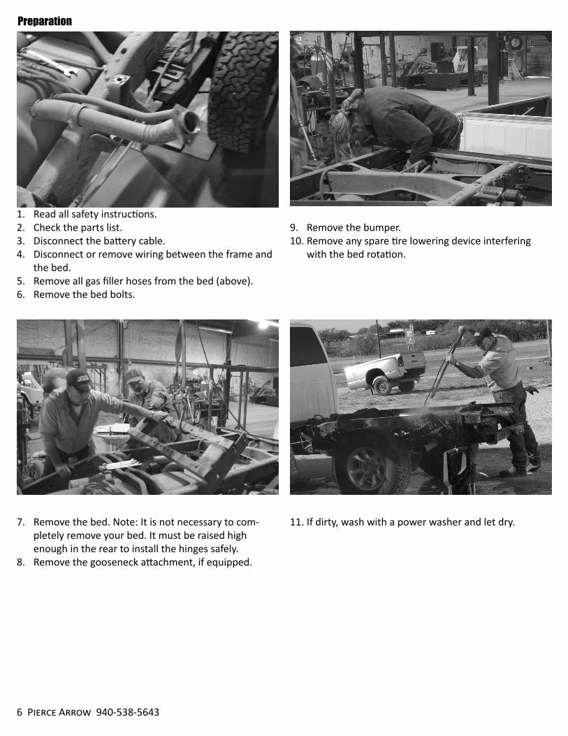
1. Read all safety instructions.2. Check the parts list.3. Disconnect the battery cable. 4. Disconnect or remove wiring between the frame and
the bed.5. Remove all gas filler hoses from the bed (above).6. Remove the bed bolts.
7. Remove the bed. Note: It is not necessary to com-pletely remove your bed. It must be raised high enough in the rear to install the hinges safely.
8. Remove the gooseneck attachment, if equipped.
Preparation
9. Remove the bumper.10. Remove any spare tire lowering device interfering
with the bed rotation.
11. If dirty, wash with a power washer and let dry.
2 T Dump Kit Installation Overview 7
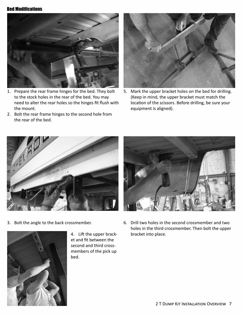
5. Mark the upper bracket holes on the bed for drilling. (Keep in mind, the upper bracket must match the location of the scissors. Before drilling, be sure your equipment is aligned).
6. Drill two holes in the second crossmember and two holes in the third crossmember. Then bolt the upper bracket into place.
Bed Modifications
1. Prepare the rear frame hinges for the bed. They bolt to the stock holes in the rear of the bed. You may need to alter the rear holes so the hinges fit flush with the mount.
2. Bolt the rear frame hinges to the second hole from the rear of the bed.
3. Bolt the angle to the back crossmember.
4. Lift the upper brack-et and fit between the second and third cross-members of the pick up bed.

8 Pierce Arrow 940-538-5643
4. Fit the rear hinges.
5. Mark the four hinge holes. Drill the holes then bolt into place.
6. Clamp the lower frame angle under the chassis to the middle and front crossmember of the frame at the rear of the cab.
1. Notch the frame in order to make room for the rear hinge by measuring 2 inches from the rear frame and bring a line diagonally so the bearing nut rests on the cut of the frame.
2. Cut through the diagonal mark.
3. Your notch should look like the above photo.
Frame Modifications

2 T Dump Kit Installation Overview 9
7. Drill two holes through the middle crossmember to match the holes on the lower frame angle.
8. Drill two holes through the front crossmember to match the holes on the lower frame angle.
9. Ensure the lower frame angle is level and center with the truck frame then bolt into place.
10. Connect the scissor to the lower frame angle by slid-ing in the greased pin.
11. Thread the cotter pins through the end of the pin on the scissor and wrap it around the pin.
12. Check your work: periodically check the fit of the bed to the frame to ensure proper contact is made be-tween the scissor and upper bracket.
13. Connect the hydrau-lic hose to the cylinder. Then connect the hydraulic hose to the pump using the elbow fitting. Ensure the hose is clear from all exhaust and moving com-ponents such as the drive shaft.
14. Return to the rear of the truck and bolt the rear hing-es to the frame using three washers (two between the hinges and one between the bolt and outer hinge).
15. Lower the bed until the scissor and upper bracket are aligned.16. Con-nect the scissor to the upper bracket using the pin and secure with a cotter pin.

10 Pierce Arrow 940-538-5643
electrical Connections
1. Use the pump bracket and bolt the pump to the passenger side frame rail approx. behind the cab. (A spacer between the pump bracket and frame may be needed to clear the truck spring hangers). If the pump is mounted more than 10 feet from the battery use #2 cable.
2. Find an accessible location for your switch on the dash that operates your pump.
3. Drill a small hole in the firewall. Use a grommet to eliminate sharp edges.
4. Install your 150 amp breaker. Connect one posi-tive connection to the solenoid and the other to the pump.
5. Zip tie the switch electrical wire under the dash.6. Run the wire from the firewall to the passenger side
of the truck frame to the pump.
7. Crimp the eyes to the #4 cable and connect to the posi-tive side of the battery. Run the cable down the passenger side of the truck frame to the pump. Secure to prevent chaffing and ensure proper clearance to prevent contact with the exhaust or any mov-ing parts.

2 T Dump Kit Installation Overview 11
Completed Project

Pierce Arrow Product Limited WarrantyPierce Arrow Inc. warrants to the original purchaser only (whether a wholesale, OEM or retail customer) that the goods, equipment, and merchandise manufactured by Pierce Arrow are free from defects in material and workmanship. The Pierce Arrow limited warranty on parts covers such items for a period of one year on mechanical and electrical from the date of shipment by Pierce Arrow. All warranties cover only the product or product parts, and are nontransferable.
OBTAINING WARRANTY SERVICE
Pierce Arrow must be notified promptly in writing, about the defect before any means of repair have been made. The merchandise must be delivered by the purchaser to Pierce Arrow in Henrietta, Texas at the purchaser’s expense. Pierce Arrow reserves the right to repair or replace the merchandise proved to be defective. The purchaser is responsible for the cost of repairs made by Pierce Arrow if the repairs are not covered by the Pierce Arrow warranty.
EXCLUSIONS
The Pierce Arrow warranty is not intended to cover normal maintenance parts, including but not limited to: wear pads, bushings, mud flaps, fender flares, light bulbs, oil filters and remote holdings. Nor is the warranty intended to cover any change or defect due to accident; misuse; improper, inadequate or unauthorized repair; failure to provide maintenance or uses for which the equipment was not intended; and normal deterioration due to weather or road conditions. Reference the owner’s manual for safety, installation, operation and maintenance guidelines.
The warranty does not bear the cost of labor, transportation, shipping damages, claimed down time, loss of profit or goodwill, or any other special, incidental, indirect, or consequential damages, concerning or related to any product or part, whether based upon negligence, strict liability, breach of contract, breach of warranty, misrepresentation, or any other legal theory.
Merchandise sold by Pierce Arrow, but not manufactured by it, is not warranted by Pierce Arrow and is subject to the manufacturer’s warranty only. The manufacturer’s warranty is available upon request.
Pierce Arrow makes no warranty, expressed or implied, to finished products manufactured or supplied by other manufacturers, and supplied from Pierce Arrow to the purchaser, including but not limited to, any vehicle to which our products is affixed to, and any accessories.
Merchandise manufactured by Pierce Arrow is not designed or intended for the movement of people and are not to be used in the operation of elevators or other improper uses. Any improper use of the product may void the warranty.
Please contact Pierce Arrow with any questions:
Pierce Arrow Inc.549 U.S. Highway 287 S.Henrietta, Texas 76365(toll free) 800-658-6301(p) 940-538-5643(f) 940-538-4382www.piercearrow.us
06062013