philos and philos long. the anatomic fixation system …synthes.vo.llnwd.net/o16/llnwmb8/int...
TRANSCRIPT
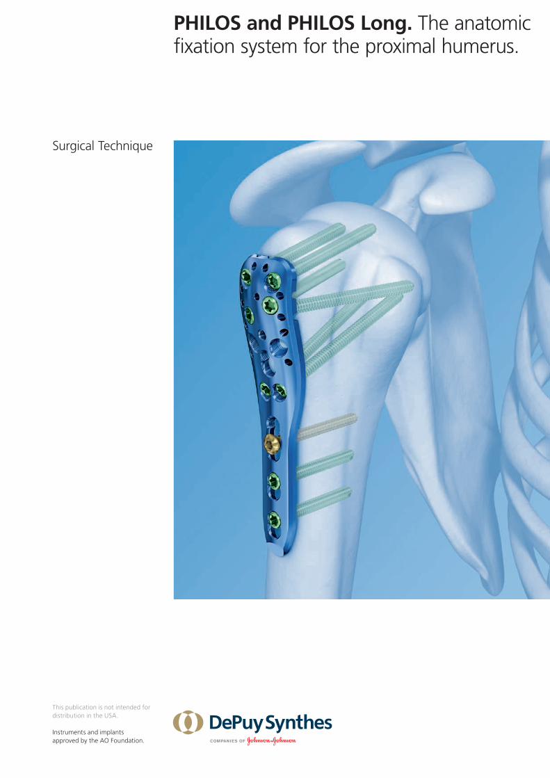
PHILOS and PHILOS Long. The anatomic fixation system for the proximal humerus.
Surgical Technique
This publication is not intended for distribution in the USA.
Instruments and implants approved by the AO Foundation.

PHILOS and PHILOS Long Surgical Technique DePuy Synthes 1
Introduction
Surgical Technique
Product Information
Bibliography 26
MRI Information 28
Table of Contents
PHILOS and PHILOS Long 2
AO Principles 4
Indications 5
Patient Positioning and Approach 6
Implantation 8
Implant Removal 22
Implants 23
Instruments 24
Image intensifier control
WarningThis description alone does not provide sufficient background for direct use of DePuy Synthes products. Instruction by a surgeon experienced in handling these products is highly recommended.
Processing, Reprocessing, Care and MaintenanceFor general guidelines, function control and dismantling of multi-part instruments, as well as processing guidelines for implants, please contact your local sales representative or refer to:http://emea.depuysynthes.com/hcp/reprocessing-care-maintenanceFor general information about reprocessing, care and maintenance of Synthes reusable devices, instrument trays and cases, as well as processing of Synthes non-sterile implants, please consult the Important Information leaflet (SE_023827) or refer to: http://emea.depuysynthes.com/hcp/reprocessing-care-maintenance

A
B
C
D
E
F
G
H
2 DePuy Synthes PHILOS and PHILOS Long Surgical Technique
PHILOS and PHILOS Long. The anatomic fixation system for the proximal humerus.
PHILOS Proximal Humeral Internal Locking System
Quick stepsfor insertion in osteoporotic bone
PHILOS – 9 proximal screw holes in section
A–E for LCP locking screws B 3.5 mm enable an angular stable construct to enhance the grip in osteoporotic bone and multi- fragment fractures
– Carefully apply for osteoporotic bone
– Optimal screw placement – 10 proximal holes for suturing to
help maintain fracture reduction
1. Reduce fracture 2. Insert plate with aiming device 3. Position the plate (either visual or
with positioning Kirschner wire)
PHILOS Long – Shaft reinforced to 3.7 mm – Distal LCP long holes for maximum
adaptability
4. Assemble outer sleeve 5. Pre-drill lateral cortex
6. Measure screw length 7. Insert screw through outer sleeve 8. Insert shaft screws

PHILOS and PHILOS Long Surgical Technique DePuy Synthes 3
PHILOS instruments
Outer sleeve
Restricted drill bit
Length probe
Quick stepsfor insertion in good bone stock
1. Reduce fracture2. Insert plate with aiming device3. Position the plate (either visual or
with positioning Kirschner wire)
4. Assemble outer sleeve and drill sleeve 5. Pre-drill the screw hole
6. Read off the required screw length 7. Remove drill sleeve and insert screw through outer sleeve
8. Insert shaft screws
One sleeve for all:drilling, measuringand screw insertion
Wings for improved sleevehold in aiming device
Blunt tip for depth probing gives feedback on bone density
Restriction at 20 mmfor controlled drilling
Enlarged shaft ensuresguidance in outer sleeve
Enlarged shaft ensuresguidance in outer sleeve
Clear and well readable scalefor depth measuring

4 DePuy Synthes PHILOS and PHILOS Long Surgical Technique
AO Principles
In 1958, the AO formulated four basic principles, which have become the guidelines for internal fixation.1, 2 Those principles as applied to PHILOS are:
Anatomic reductionFracture reduction and fixation to restore anatomical relationships.
Stable fixationStability by fixation or splintage, as the personality of the fracture and the injury requires. The products optimize purchase for maximum compression and stability.
Preservation of blood supplyPreservation of the blood supply to soft tissue and bone by careful handling, atraumatic surgery. Use of surgical tech-nique that minimizes disruption of soft tissue and preserves vascular blood flow for bone healing. A limited-contact plate design reduces plate-to-bone contact and helps to preserve the periosteal blood supply.
Early, active mobilizationEarly and safe mobilization of the part and patient. The im-plants, combined with AO technique, provide stable fracture fixation with minimal trauma to vascular supply. Plate fea-tures combined with AO technique create an environment for bone healing, expediting return to function.
1 Müller ME, Allgöwer M, Schneider R, Willenegger H (1995) Manual of Internal Fixation. 3rd, expanded and completely revised ed. 1991. Berlin, Heidelberg, New York: Springer
2 Rüedi TP, Buckley RE, Moran CG (2007) AO Principles of Fracture Management. 2nd expanded ed. 2002. Stuttgart, New York: Thieme

PHILOS and PHILOS Long Surgical Technique DePuy Synthes 5
Indications
PHILOS – Dislocated two-, three-, and four-fragment fractures
of the proximal humerus, including fractures involving osteopenic bone
– Pseudarthroses in the proximal humerus – Osteotomies in the proximal humerus
PHILOS Long – As for PHILOS, but for fractures extending into the shaft
or fractures without medial support

6 DePuy Synthes PHILOS and PHILOS Long Surgical Technique
1Position the patient
Place the patient in the beach chair position or supine position on a radiolucent table.
Ensure the fluoroscope is positioned in a way that allows visualization of the proximal humerus in two axes (AP and lateral/axial).
Prepare the patient’s arm so that it can be mobilized intraoperatively.
Patient Positioning and Approach

PHILOS and PHILOS Long Surgical Technique DePuy Synthes 7
2Approach
A deltopectoral or transdeltoid approach is recommended.

8 DePuy Synthes PHILOS and PHILOS Long Surgical Technique
1Reduce fracture and fix temporarily
Proper reduction of the fracture is crucial for good bone healing and function. In some cases closed reduction before prepping the patient is beneficial.
Reduce the head fragments and check the reduction under image intensifier control.
Kirschner wires can be used for reduction as joysticks in the fragments as well as for temporary fixation. Ensure that Kirschner wires do not interfere with correct plate place-ment.
Note: The locking screws are not suitable for reduction since they cannot exert compression. The head fragments must be reduced before insertion of locking screws.
SuturingProvisionally reduce the tubercles using sutures through the insertions of the musculi subscapularis, infra- and supra- spinatus. The sutures will help to maintain the stability of the reconstruction when fixing them to the plate later.
Insertion of sutures is especially recommended in weak bone where only short screws can be used due to the risk of pene-tration through settling.
Implantation

PHILOS and PHILOS Long Surgical Technique DePuy Synthes 9
2Prepare plate position
For optimal plate positioning, insert two positioning Kirschner wires 2 – 4 mm lateral to the bicipital groove and 5 – 7 mm below the tip of the greater tubercule.
Note: Placing the plate too high increases the risk of subacromial impingement. Placing the plate too low can prevent the optimal distribution of screws in the humeral head and make it impossible to insert screws in section “E” (see page 2).
Alternative technique
Instruments
323-050 PHILOS Aiming Device, with Noseor 03.122.056
Determine the position of the plate using the PHILOS aiming device with nose (see step 3 for attachment of the aiming device). Insert a Kirschner wire into the proximal guide hole below the rotator cuff so that the Kirschner wire aims at the proximal joint surface.

10 DePuy Synthes PHILOS and PHILOS Long Surgical Technique
3Attach aiming device to plate
Instruments
03.122.057 PHILOS Aiming Device, without Nose
323-050 PHILOS Aiming Device, with Noseor03.122.056
311.431 Handle with Quick Coupling
314.030 Screwdriver Shaft hexagonal
Insert the stabilization pin of the aiming device in the spe-cially provided hole on the PHILOS plate. Use the screwdriver to tighten the securing screw of the aiming device.
Implantation

PHILOS and PHILOS Long Surgical Technique DePuy Synthes 11
4Insert plate and fix temporarily
Instruments
323-053 Outer Sleeve 6.0/5.0 for PHILOS Aimingor Device03.122.053
323-054 Drill Sleeve 5.0/2.9, for No. 03.122.053or03.122.054
323-055 Centering Sleeve for Kirschner Wireor B 1.6 mm, for No. 03.122.05403.122.055
Insert the plate and position it on the reduced bone between the Kirschner wires, which were set in step 2.
Attach the plate temporarily with a cortex screw in the elongated combi-hole in the plate shaft (see step 7 for shaft screw insertion).
If required, use Kirschner wires through the triple sleeve system for temporary fixation of the humeral head.

12 DePuy Synthes PHILOS and PHILOS Long Surgical Technique
Implantation
Option: Temporarily reduce with pull reduction device
Instruments
03.122.059 Pull Reduction Device for use with No. 03.122.060 for Drill Sleeves
03.122.060 Wing Nut for Pull Reduction for use with No. 03.122.059 for Drill Sleeves
In good bone stock, the pull reduction device can optionally be used for temporary reduction. Using a power tool, insert the pull reduction device through the drill sleeve to the desired depth. Slide the wing nut over the wire and tighten. In this way, bone fragments are pulled towards the plate.
Warning: Do not penetrate the joint surface with the pull reduction device.

PHILOS and PHILOS Long Surgical Technique DePuy Synthes 13
5Predrill the lateral cortex and determine proximal screw length
Proximal humerus fractures are common in osteoporotic bone. The following technique describes screw measuring optimized for weak bone quality.
If good bone stock is present, change to options A or B for pre-drilling the screw hole and depth measuring.
Instruments
323-053 Outer Sleeve 6.0/5.0 for PHILOSor Aiming Device03.122.053
03.122.051 Drill Bit B 2.8 mm, with Stop, for Quick Coupling
03.122.052 Length Probe for Nos. 03.122.053 and 03.122.058
Insert the outer sleeve in the desired hole of the aiming device. Predrill the lateral cortex using the drill bit with stop through the outer sleeve.
Repeat this step for all required proximal screw holes.
Optional instrument
03.122.058 Drill Sleeve 6.0/2.9 with thread
Use the drill sleeve with thread independently from the aiming device.

14 DePuy Synthes PHILOS and PHILOS Long Surgical Technique
Implantation
Use the length probe through the outer sleeve and push it carefully into the humeral head. Stop pushing when increased bone density is felt. Read off the required screw length from the length probe.
Warning: Do not push the length probe through the joint surface.
Note: The tip of the length probe should be located approxi-mately 5 – 8 mm below the joint surface.
Alternative techniques for good bone stock
If the bone stock is good, choose one of the following options:
Option A: Use a 2.8 mm drill bit through the drill sleeve and drill 5 – 8 mm below the joint surface. Read off the required screw length from the drill bit.

PHILOS and PHILOS Long Surgical Technique DePuy Synthes 15
Option B: Check the subsequent position of the screws using Kirschner wires. Attach the triple sleeve system, con-sisting of a outer sleeve, a drill sleeve, and a centering sleeve for the Kirschner wire onto the aiming device and insert a Kirschner wire 1.6 mm, 150 mm long.
Check the position of the Kirschner wire. The tip of the Kirschner wire should be located in the subchondral bone (5 – 8 mm below the joint surface).
Slide the PHILOS direct measuring device for Kirschner wire 1.6 mm over the Kirschner wire and determine the length of the required screw.

16 DePuy Synthes PHILOS and PHILOS Long Surgical Technique
Implantation
6Insert proximal screws
Instruments
511-115or511.770 Torque limiter, 1.5 Nmor511.773
314-036 Screwdriver Shaft hexagonal or314.116 Screwdriver Shaft Stardrive T15
311.431 Handle with Quick Coupling
Insert the screw with the appropriate screwdriver shaft (hexagonal or Stardrive recess) and 1.5 Nm torque limiting attachment through the outer sleeve. The sleeve ensures that the locking screw is correctly locked in the plate. The angular stability is reduced if a locking screw is inserted obliquely.
Insert the screw manually or with power until a click is heard. If using power, reduce speed when tightening the head of the locking screw into the plate.
Repeat the above step for all required proximal screw holes.
Note: The plate should be secured with at least 4 proximal screws. In poor bone stock, multiple fixation points using all screws is recommended.

PHILOS and PHILOS Long Surgical Technique DePuy Synthes 17
7Insert shaft screws: Cortex
Instrument
323.360 Universal Drill Sleeve 3.5
Plate holes in the plate shaft (distal to section E) are LCP combi-holes (see page 2). An LCP combi-hole can be fixed with a cortex screw to generate interfragmentary compres-sion. In this case, the screws are inserted according to the technique for fixing LC-DCP standard plates, but using the universal drill guide instead of the LC-DCP drill guide.
8Insert shaft screws: Locking
8aInsert LCP drill sleeve in shaft hole
Instrument
323.027 LCP Drill Sleeve 3.5
Carefully screw the LCP drill sleeve into the threaded section of the desired combi-hole until it is gripped completely by the thread. The LCP drill sleeve ensures that the locking screw is correctly locked in the plate. The angular stability is reduced if a locking screw is inserted obliquely.

18 DePuy Synthes PHILOS and PHILOS Long Surgical Technique
Implantation
8bPredrill screw hole and insert screw
Instruments
310.284 LCP Drill bit B 2.8 mm
319-010 Depth gauge
511-115 or511.770 Torque limiter, 1.5 Nmor 511.773
314-036 Screwdriver Shaft hexagonal or314.116 Screwdriver Shaft Stardrive T15
311.431 Handle for Torque Limiter
Predrill the screw hole with a 2.8 mm drill bit passing through both cortices.
Remove the LCP drill sleeve.
Using the depth gauge, determine the required screw length.

PHILOS and PHILOS Long Surgical Technique DePuy Synthes 19
Insert the locking screws manually or with the use of a power tool as described in step 6. The distal locking screws must be locked in the combi-hole at an angle of 90° to ensure optimal stability.

20 DePuy Synthes PHILOS and PHILOS Long Surgical Technique
Implantation
9Attach sutures
Remove the aiming device from the plate.
Knot the sutures through the designated holes in the plate if this has not already been done. This construct functions as a tension band and transmits the forces of the rotator cuff over the plate and into the shaft, while preventing fragment displacement during the early rehabilitation period.

PHILOS and PHILOS Long Surgical Technique DePuy Synthes 21
10Final check
Before closing the wound, check the screw lengths under image intensifier control in the full range of gleno-humeral- motion and ensure that they do not penetrate the articular surface.
Note: It is important to check the screw lengths in all planes as their angulation and direction may be difficult to visualize.
Check the stability of the suture fixation. The sutures must not rupture during motion.

22 DePuy Synthes PHILOS and PHILOS Long Surgical Technique
Implant Removal
Instruments
314-036 Screwdriver Shaft hexagonalor314.116 Screwdriver Shaft Stardrive T15
311.431 Handle with Quick Coupling
309.521 Extraction Screw for Screws B 3.5 mm
To remove the plate, first unlock all screws with the screw-driver before removing them definitively in a second step, otherwise the plate may rotate while the last screw is being removed and cause soft tissue damage.
If the LCP locking screws cannot be removed with the screw-driver (e.g., if the screw recess is damaged), use an extraction screw with lefthanded thread. Loosen the screw by turning the handle counterclockwise.

PHILOS and PHILOS Long Surgical Technique DePuy Synthes 23
Implants
PHILOS – Proximal Humeral Plate 3.5Titanium Shaft holes Length (mm)
441.901 S 3 90
441.903 S 5 114
Screws used with PHILOS
412-101S-126S Locking Screw Stardrive B 3.5 mm, length 10 – 70 mm, self-tapping
413-010S-070S Locking Screw B 3.5 mm, length 10 – 70 mm, self-tapping, with hexagonal recess
404-010S-040S Cortex Screw B 3.5 mm, length 10 – 70 mm, self-tapping, with hexagonal recess
PHILOS Long – Proximal Humeral Plate 3.5
Titanium Shaft holes Length (mm)
241.916 441.916 3 106
241.917 441.917 4 124
241.918 441.918 5 142
241.919 441.919 6 160
241.920 441.920 7 178
241.921 441.921 8 196
241.922 441.922 9 214
241.923 441.923 10 232
241.924 441.924 11 250
241.925 441.925 12 268
241.926 441.926 13 286

24 DePuy Synthes PHILOS and PHILOS Long Surgical Technique
Instruments
PHILOS sizing templates
Shaft holes
03.122.003 3
option03.122.005 long
03.122.051 Drill Bit B 2.8 mm, with Stop, for Quick Coupling
03.122.052 Length Probe for Nos. 03.122.053 and 03.122.058
323-053 Outer Sleeve 6.0/5.0 for PHILOSor Aiming Device03.122.053
323-054 Drill Sleeve 5.0/2.9, for No. 03.122.053or03.122.054
323-055 Centering Sleeve for Kirschner Wireor B 1.6 mm, for No. 03.122.05403.122.055

PHILOS and PHILOS Long Surgical Technique DePuy Synthes 25
323-050 PHILOS Aiming Device, with Nose
03.122.057 PHILOS Aiming Device, without Nose
03.122.060 Wing Nut for Pull Reduction for use with No. 03.122.059 for Drill Sleeves
Optional instruments
03.122.058 Drill Sleeve 6.0/2.9 with thread
03.122.059 Pull Reduction Device for use with No. 03.122.060 for Drill Sleeves

26 DePuy Synthes PHILOS and PHILOS Long Surgical Technique
Bibliography
Babst R, Brunner F. Plating in Proximal Humeral Fractures. Eur J Trauma Emerg Surg 2007; 33:345
Brunner F, Sommer C, Bahrs C, Heuwinkel R, Hafner C, Rill-mann P, Kohut G, Ekelund A, Muller M, Audigé L, Babst R. Open Reduction and Internal Fixation of Proximal Humerus Fractures Using a Proximal Humeral Locked Plate: A Prospec-tive Multicenter Analysis. J Orthop Trauma. 2009 Mar; 23(3):163-72

PHILOS and PHILOS Long Surgical Technique DePuy Synthes 27

28 DePuy Synthes PHILOS and PHILOS Long Surgical Technique
MRI Information
Torque, Displacement and Image Artifacts according to ASTM F 2213-06, ASTM F 2052-06e1 and ASTM F2119-07Non-clinical testing of worst case scenario in a 3 T MRI system did not reveal any relevant torque or displacement of the construct for an experimentally measured local spatial gradient of the magnetic field of 3.69 T/m. The largest image artifact extended approximately 169 mm from the construct when scanned using the Gradient Echo (GE). Testing was conducted on a 3 T MRI system.
Radio-Frequency-(RF-)induced heating according to ASTM F2182-11aNon-clinical electromagnetic and thermal testing of worst case scenario lead to peak temperature rise of 9.5 °C with an average temperature rise of 6.6 °C (1.5 T) and a peak temperature rise of 5.9 °C (3 T) under MRI Conditions using RF Coils [whole body averaged specific absorption rate (SAR) of 2 W/kg for 6 minutes (1.5 T) and for 15 minutes (3 T)].
Precautions: The above mentioned test relies on non-clini-cal testing. The actual temperature rise in the patient will depend on a variety of factors beyond the SAR and time of RF application. Thus, it is recommended to pay particular attention to the following points: – It is recommended to thoroughly monitor patients under-
going MR scanning for perceived temperature and/or pain sensations.
– Patients with impaired thermo regulation or temperature sensation should be excluded from MR scanning proce-dures.
– Generally it is recommended to use a MR system with low field strength in the presence of conductive implants. The employed specific absorption rate (SAR) should be reduced as far as possible.
– Using the ventilation system may further contribute to reduce temperature increase in the body.


0123
Synthes GmbHEimattstrasse 34436 OberdorfSwitzerlandTel: +41 61 965 61 11Fax: +41 61 965 66 00www.depuysynthes.com
This publication is not intended for distribution in the USA.
All surgical techniques are available as PDF files at www.depuysynthes.com/ifu ©
DeP
uy S
ynth
es T
raum
a, a
div
isio
n of
Syn
thes
Gm
bH. 2
015.
A
ll rig
hts
rese
rved
. 03
6.0
00.
166
DSE
M/T
RM
/081
5/0
449
09
/15