lcp distal humerus plates. the anatomic fixation system ...synthes.vo.llnwd.net/o16/llnwmb8/int...
TRANSCRIPT
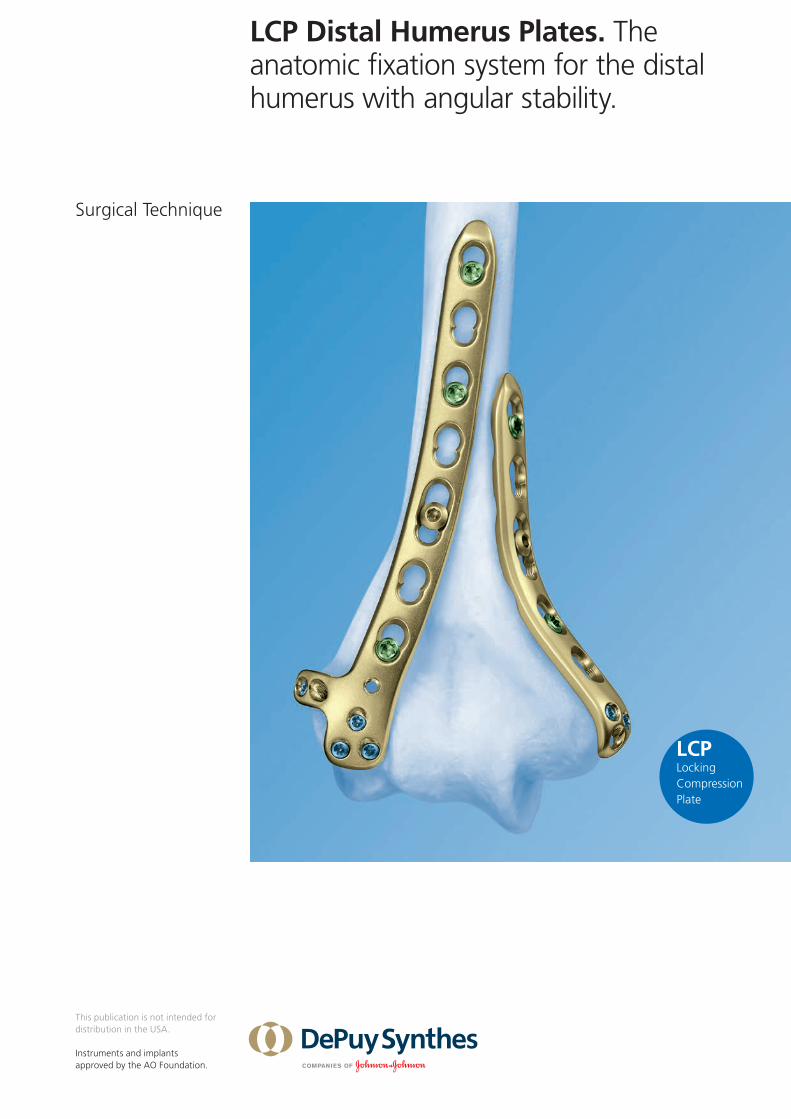
LCP Distal Humerus Plates. The anatomic fixation system for the distal humerus with angular stability.
Surgical Technique
This publication is not intended for distribution in the USA.
Instruments and implants approved by the AO Foundation.

Image intensifier control
This description alone does not provide sufficient background for direct use of DePuy Synthes products. Instruction by a surgeon experienced in handling these products is highly recommended.
Processing, Reprocessing, Care and MaintenanceFor general guidelines, function control and dismantling of multi-part instruments, as well as processing guidelines for implants, please contact your local sales representative or refer to:http://emea.depuysynthes.com/hcp/reprocessing-care-maintenanceFor general information about reprocessing, care and maintenance of Synthes reusable devices, instrument trays and cases, as well as processing of Synthes non-sterile implants, please consult the Important Information leaflet (SE_023827) or refer to: http://emea.depuysynthes.com/hcp/reprocessing-care-maintenance
LCP Distal Humerus Plates Surgical Technique DePuy Synthes 1
Table of Contents
LCP Distal Humerus Plates 2
AO Principles 4
Indications and contraindications 5
Preparation 6
Dorsolateral plate with support 9
Medial Plate 14
Fixing the shaft 16
Option: Dorsolateral plate without support 18
Option: Positioning and compression device PCD 20
Option: LCP Metaphyseal Plate 3.5 for distal medial humerus 24
Implant removal 26
Implants 27
Implants Option: LCP Metaphyseal Plate 3.5 for distal medial humerus 28
Instruments 30
MRI Information 33
2 DePuy Synthes LCP Distal Humerus Plates Surgical Technique
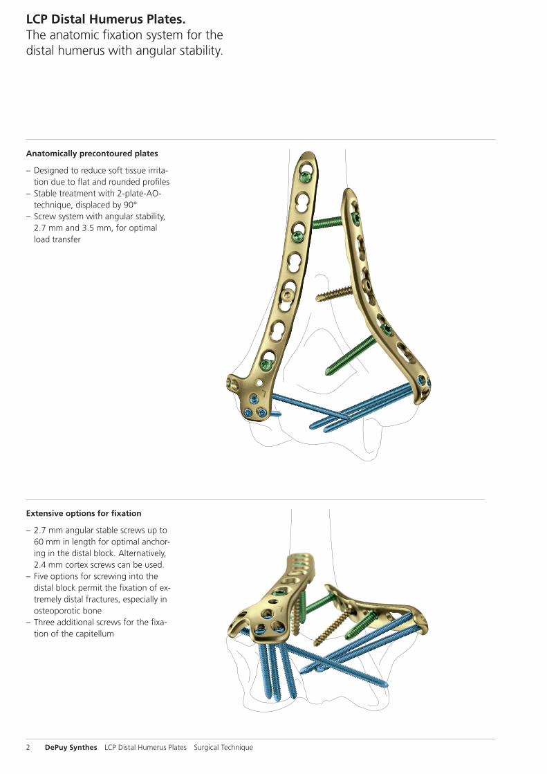
Anatomically precontoured plates
– Designed to reduce soft tissue irrita-tion due to flat and rounded profiles
– Stable treatment with 2-plate-AO-technique, displaced by 90°
– Screw system with angular stability, 2.7 mm and 3.5 mm, for optimal load transfer
Extensive options for fixation
– 2.7 mm angular stable screws up to 60 mm in length for optimal anchor-ing in the distal block. Alternatively, 2.4 mm cortex screws can be used.
– Five options for screwing into the distal block permit the fixation of ex-tremely distal fractures, especially in osteoporotic bone
– Three additional screws for the fixa-tion of the capitellum
LCP Distal Humerus Plates. The anatomic fixation system for the distal humerus with angular stability.
LCP Distal Humerus Plates Surgical Technique DePuy Synthes 3
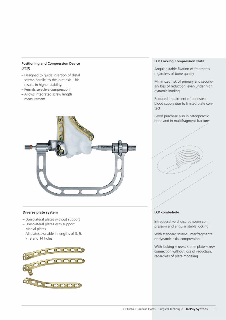
Positioning and Compression Device (PCD)
– Designed to guide insertion of distal screws parallel to the joint axis. This results in higher stability.
– Permits selective compression – Allows integrated screw length
measurement
Diverse plate system
– Dorsolateral plates without support – Dorsolateral plates with support– Medial plates– All plates available in lengths of 3, 5,
7, 9 and 14 holes
LCP combi-hole
Intraoperative choice between com-pression and angular stable locking
With standard screws: interfragmental or dynamic-axial compression
With locking screws: stable plate-screw connection without loss of reduction, regardless of plate modeling
LCP Locking Compression Plate
Angular stable fixation of fragments regardless of bone quality
Minimized risk of primary and second-ary loss of reduction, even under high dynamic loading
Reduced impairment of periosteal blood supply due to limited plate con-tact
Good purchase also in osteoporotic bone and in multifragment fractures
AO Principles
1 Müller ME, Allgöwer M, Schneider R, Willenegger H. Manual of Internal Fixation. 3rd ed. Berlin, Heidelberg, New York: Springer. 1991.
2 Rüedi TP, Buckley RE, Moran CG. AO Principles of Fracture Management. 2nd ed. Stuttgart, New York: Thieme. 2007.
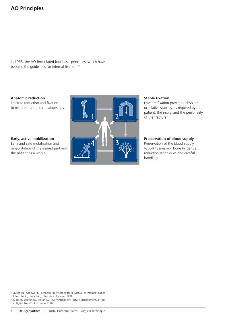
Stable fixationFracture fixation providing absolute or relative stability, as required by the patient, the injury, and the personality of the fracture.
Anatomic reductionFracture reduction and fixation to restore anatomical relationships.
Early, active mobilizationEarly and safe mobilization and rehabilitation of the injured part and the patient as a whole.
Preservation of blood supplyPreservation of the blood supply to soft tissues and bone by gentle reduction techniques and careful handling.
In 1958, the AO formulated four basic principles, which have become the guidelines for internal fixation1,2.
1
4
2
3
4_Priciples_03.pdf 1 05.07.12 12:08
4 DePuy Synthes Expert Lateral Femoral Nail Surgical Technique
AO PRINCIPLES
In 1958, the AO formulated four basic principles, which have become the guidelines for internal fixation1, 2.
1 Müller ME, M Allgöwer, R Schneider, H Willenegger. Manual of Internal Fixation. 3rd ed. Berlin Heidelberg New York: Springer. 1991.
2 Rüedi TP, RE Buckley, CG Moran. AO Principles of Fracture Management. 2nd ed. Stuttgart, New York: Thieme. 2007.
Anatomic reductionFracture reduction and fixation to restore anatomical relationships.
Early, active mobilizationEarly and safe mobilization and rehabilitation of the injured part and the patient as a whole.
Stable fixationFracture fixation providing abso-lute or relative stability, as required by the patient, the injury, and the personality of the fracture.
Preservation of blood supplyPreservation of the blood supply to soft tissues and bone by gentle reduction techniques and careful handling.
4 DePuy Synthes LCP Distal Humerus Plates Surgical Technique
LCP Distal Humerus Plates Surgical Technique DePuy Synthes 5
Indications and contraindications
Indications – Intraarticular fractures of the distal humerus – Supracondylar fractures of the distal humerus – Non-unions of the distal humerus
Contraindications – Acute infections – Children in the growth phase
Indications for LCP Metaphyseal Plate 3.5 for distal medial humerus.The LCP Metaphyseal Plate 3.5 is indicated for use for the treatment of juxta-articular distal humerus fractures.
6 DePuy Synthes LCP Distal Humerus Plates Surgical Technique
Preparation
Note: For information on fixation principles using conven-tional and locked plating techniques, please refer to the LCP Locking Compression Plate Surgical Technique (DSEM/TRM/0115/0278).
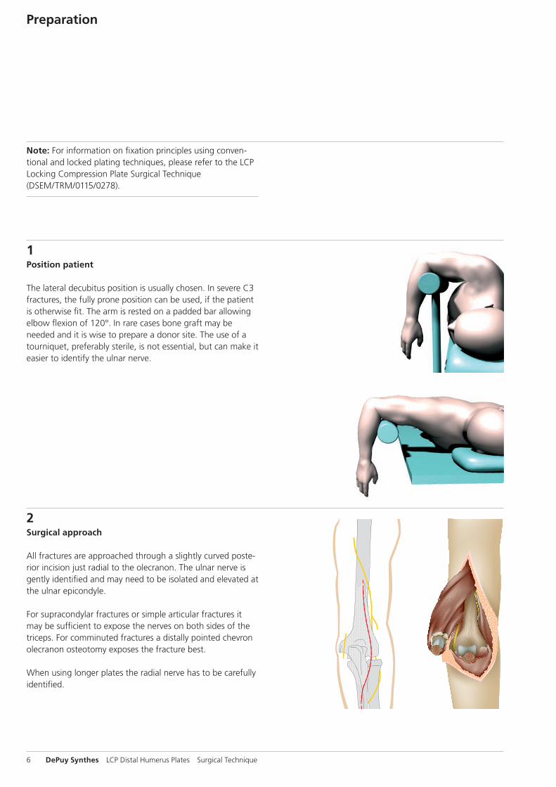
1Position patient
The lateral decubitus position is usually chosen. In severe C3 fractures, the fully prone position can be used, if the patient is otherwise fit. The arm is rested on a padded bar allowing elbow flexion of 120°. In rare cases bone graft may be needed and it is wise to prepare a donor site. The use of a tourniquet, preferably sterile, is not essential, but can make it easier to identify the ulnar nerve.
2Surgical approach
All fractures are approached through a slightly curved poste-rior incision just radial to the olecranon. The ulnar nerve is gently identified and may need to be isolated and elevated at the ulnar epicondyle.
For supracondylar fractures or simple articular fractures it may be sufficient to expose the nerves on both sides of the triceps. For comminuted fractures a distally pointed chevron olecranon osteotomy exposes the fracture best.
When using longer plates the radial nerve has to be carefully identified.
LCP Distal Humerus Plates Surgical Technique DePuy Synthes 7
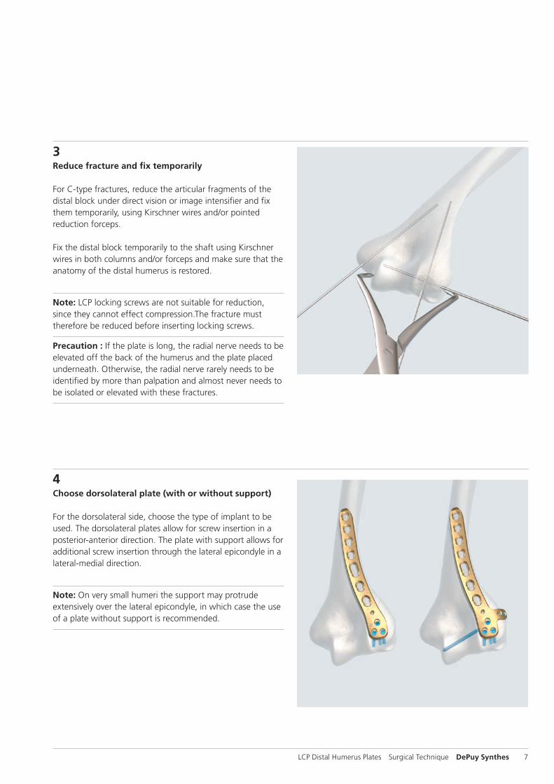
3Reduce fracture and fix temporarily
For C-type fractures, reduce the articular fragments of the distal block under direct vision or image intensifier and fix them temporarily, using Kirschner wires and/or pointed reduction forceps.
Fix the distal block temporarily to the shaft using Kirschner wires in both columns and/or forceps and make sure that the anatomy of the distal humerus is restored.
Note: LCP locking screws are not suitable for reduction, since they cannot effect compression.The fracture must therefore be reduced before inserting locking screws.
Precaution : If the plate is long, the radial nerve needs to be elevated off the back of the humerus and the plate placed underneath. Otherwise, the radial nerve rarely needs to be identified by more than palpation and almost never needs to be isolated or elevated with these fractures.
4Choose dorsolateral plate (with or without support)
For the dorsolateral side, choose the type of implant to be used. The dorsolateral plates allow for screw insertion in a posterior-anterior direction. The plate with support allows for additional screw insertion through the lateral epicondyle in a lateral-medial direction.
Note: On very small humeri the support may protrude extensively over the lateral epicondyle, in which case the use of a plate without support is recommended.
8 DePuy Synthes LCP Distal Humerus Plates Surgical Technique
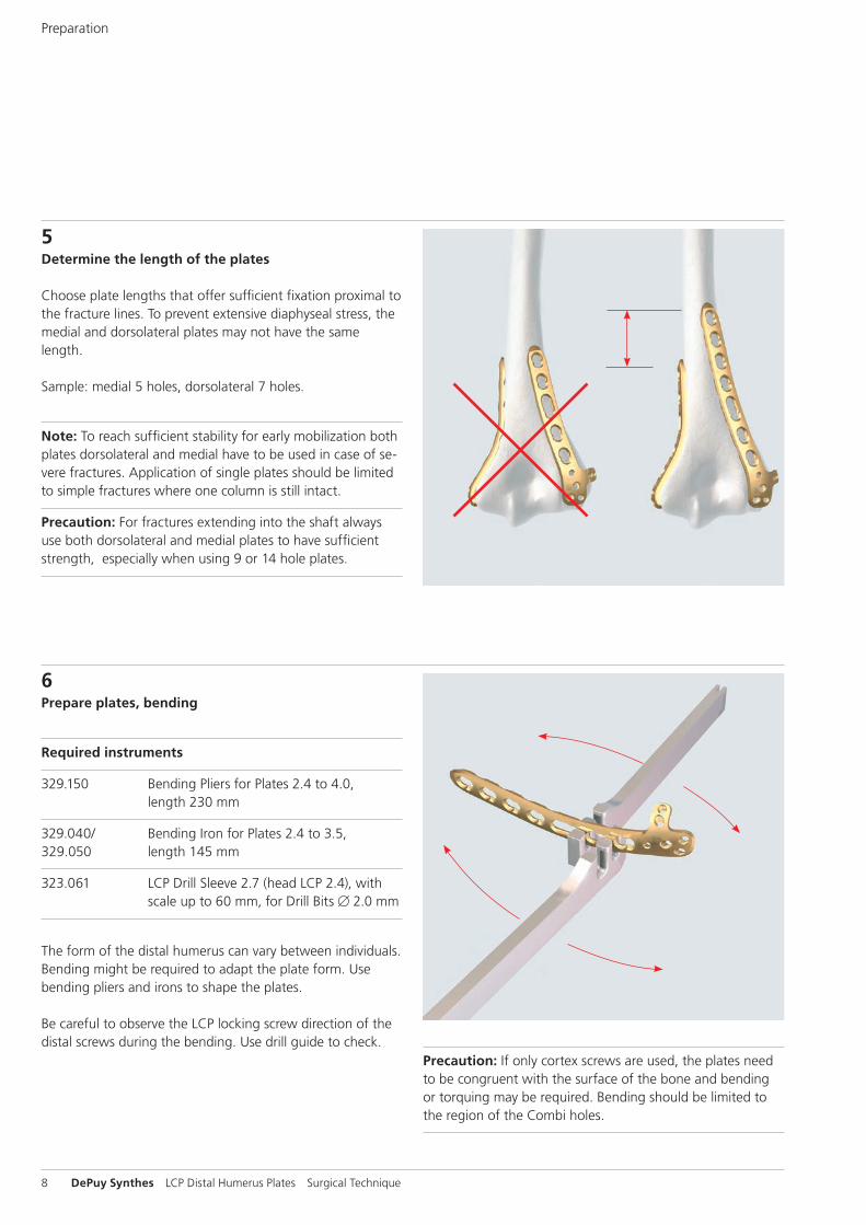
5Determine the length of the plates
Choose plate lengths that offer sufficient fixation proximal to the fracture lines. To prevent extensive diaphyseal stress, the medial and dorsolateral plates may not have the same length.
Sample: medial 5 holes, dorsolateral 7 holes.
Note: To reach sufficient stability for early mobilization both plates dorsolateral and medial have to be used in case of se-vere fractures. Application of single plates should be limited to simple fractures where one column is still intact.
Precaution: For fractures extending into the shaft always use both dorsolateral and medial plates to have sufficient strength, especially when using 9 or 14 hole plates.
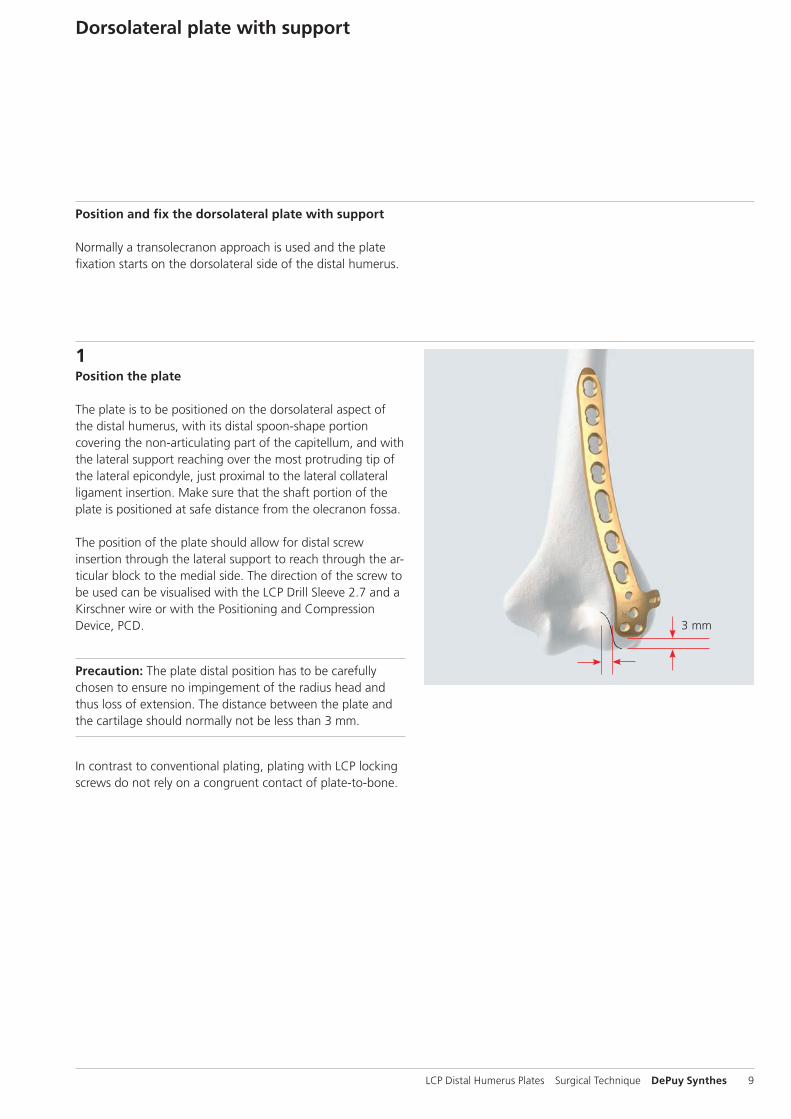
6Prepare plates, bending
Required instruments
329.150 Bending Pliers for Plates 2.4 to 4.0, length 230 mm
329.040/ Bending Iron for Plates 2.4 to 3.5, 329.050 length 145 mm
323.061 LCP Drill Sleeve 2.7 (head LCP 2.4), with scale up to 60 mm, for Drill Bits B 2.0 mm
The form of the distal humerus can vary between individuals. Bending might be required to adapt the plate form. Use bending pliers and irons to shape the plates.
Be careful to observe the LCP locking screw direction of the distal screws during the bending. Use drill guide to check.
Precaution: If only cortex screws are used, the plates need to be congruent with the surface of the bone and bending or torquing may be required. Bending should be limited to the region of the Combi holes.
Preparation
3 mm
LCP Distal Humerus Plates Surgical Technique DePuy Synthes 9
Dorsolateral plate with support
Position and fix the dorsolateral plate with support
Normally a transolecranon approach is used and the plate fixation starts on the dorsolateral side of the distal humerus.
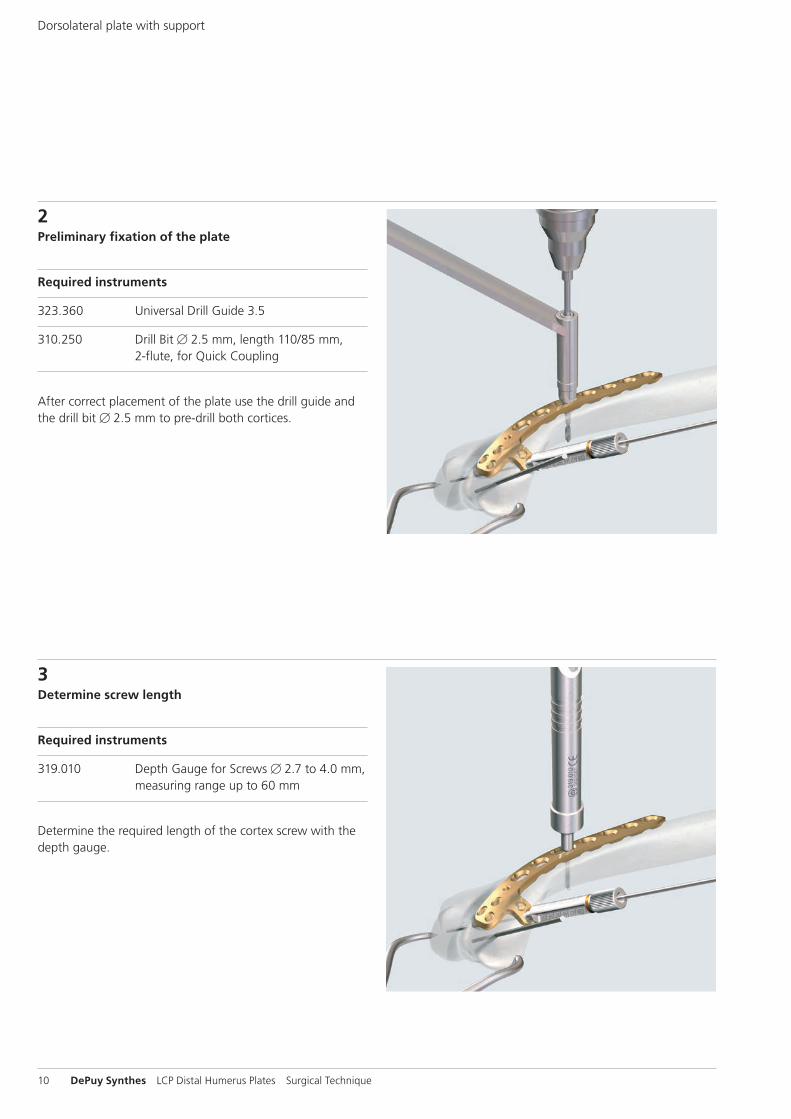
1Position the plate
The plate is to be positioned on the dorsolateral aspect of the distal humerus, with its distal spoon-shape portion covering the non-articulating part of the capitellum, and with the lateral support reaching over the most protruding tip of the lateral epicondyle, just proximal to the lateral collateral ligament inser tion. Make sure that the shaft portion of the plate is positioned at safe distance from the olecranon fossa.
The position of the plate should allow for distal screw insertion through the lateral support to reach through the ar-ticular block to the medial side. The direction of the screw to be used can be visualised with the LCP Drill Sleeve 2.7 and a Kirschner wire or with the Positioning and Compression Device, PCD.
Precaution: The plate distal position has to be carefully chosen to ensure no impingement of the radius head and thus loss of extension. The distance between the plate and the cartilage should normally not be less than 3 mm.
In contrast to conventional plating, plating with LCP locking screws do not rely on a congruent contact of plate-to-bone.
10 DePuy Synthes LCP Distal Humerus Plates Surgical Technique
3Determine screw length
Required instruments
319.010 Depth Gauge for Screws B 2.7 to 4.0 mm, measuring range up to 60 mm
Determine the required length of the cortex screw with the depth gauge.
2Preliminary fixation of the plate
Required instruments
323.360 Universal Drill Guide 3.5
310.250 Drill Bit B 2.5 mm, length 110/85 mm, 2-flute, for Quick Coupling
After correct placement of the plate use the drill guide and the drill bit B 2.5 mm to pre-drill both cortices.
Dorsolateral plate with support
LCP Distal Humerus Plates Surgical Technique DePuy Synthes 11
5Pre-drill distal hole
Required instruments
323.061 LCP Drill Sleeve 2.7 (head LCP 2.4), with scale up to 60 mm, for Drill Bits B 2.0 mm
323.062 Drill Bit B 2.0 mm, with double marking, length 140/115mm, 3-flute, for Quick Coupling
Screw the LCP Drill Sleeve into one of the threaded holes of the distal part of the plate and pre-drill a hole with the drill bit B 2.0 mm. Check the depth of the drill bit under im-age intensifier.
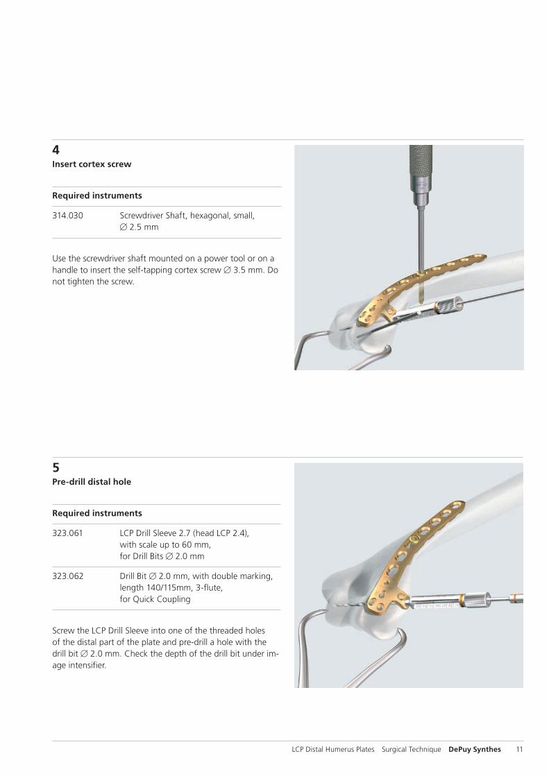
4Insert cortex screw
Required instruments
314.030 Screwdriver Shaft, hexagonal, small, B 2.5 mm
Use the screwdriver shaft mounted on a power tool or on a handle to insert the self-tapping cortex screw B 3.5 mm. Do not tighten the screw.
12 DePuy Synthes LCP Distal Humerus Plates Surgical Technique
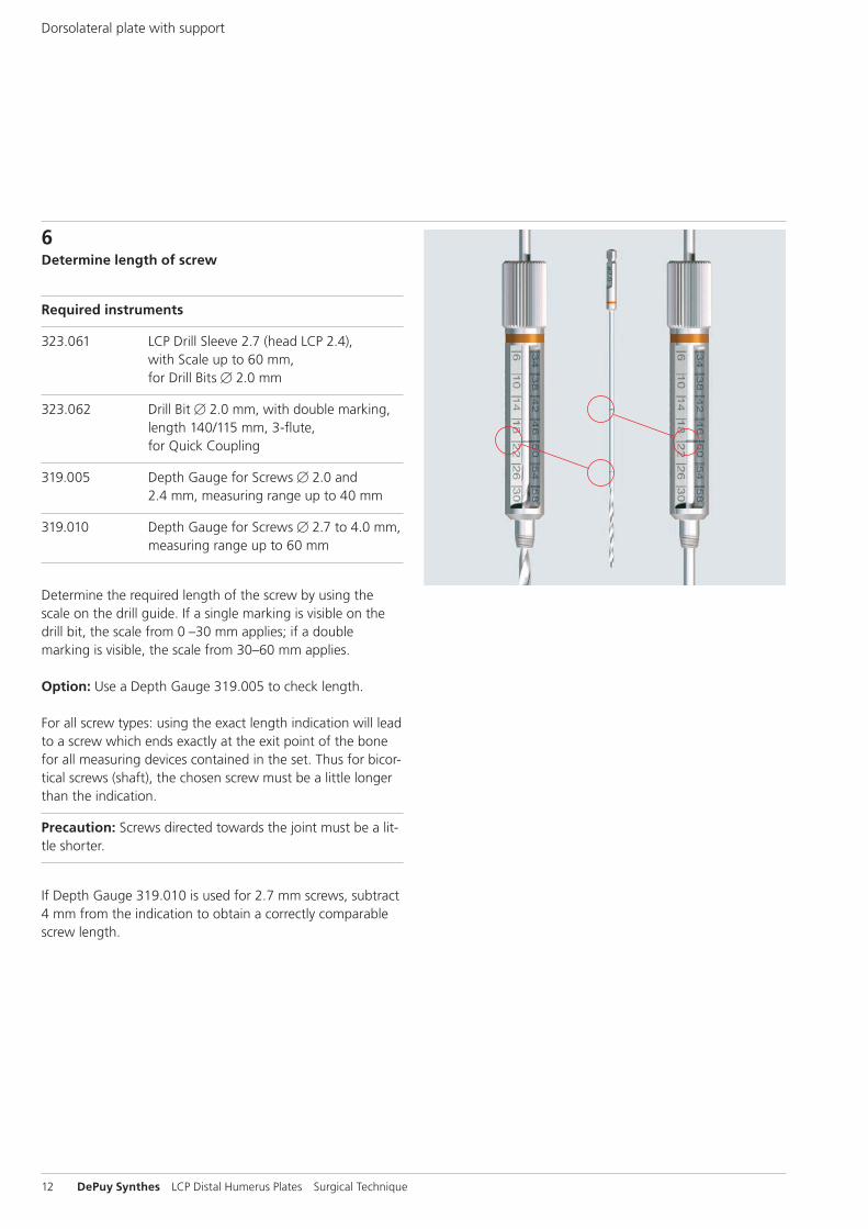
6Determine length of screw
Required instruments
323.061 LCP Drill Sleeve 2.7 (head LCP 2.4), with Scale up to 60 mm, for Drill Bits B 2.0 mm
323.062 Drill Bit B 2.0 mm, with double marking, length 140/115 mm, 3-flute, for Quick Coupling
319.005 Depth Gauge for Screws B 2.0 and 2.4 mm, measuring range up to 40 mm
319.010 Depth Gauge for Screws B 2.7 to 4.0 mm, measuring range up to 60 mm
Determine the required length of the screw by using the scale on the drill guide. If a single marking is visible on the drill bit, the scale from 0 –30 mm applies; if a double marking is visible, the scale from 30–60 mm applies.
Option: Use a Depth Gauge 319.005 to check length.
For all screw types: using the exact length indication will lead to a screw which ends exactly at the exit point of the bone for all measuring devices contained in the set. Thus for bicor-tical screws (shaft), the chosen screw must be a little longer than the indication.
Precaution: Screws directed towards the joint must be a lit-tle shorter.
If Depth Gauge 319.010 is used for 2.7 mm screws, subtract 4 mm from the indication to obtain a correctly comparable screw length.
Dorsolateral plate with support
LCP Distal Humerus Plates Surgical Technique DePuy Synthes 13
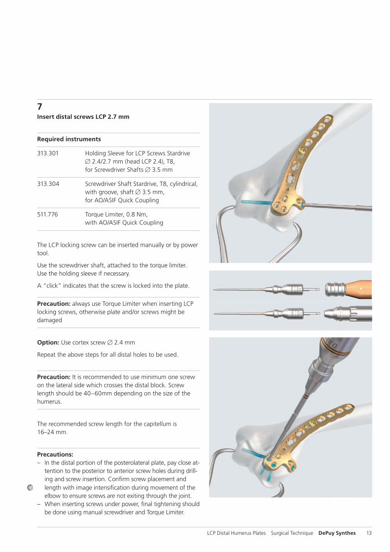
7Insert distal screws LCP 2.7 mm
Required instruments
313.301 Holding Sleeve for LCP Screws Stardrive B 2.4/2.7 mm (head LCP 2.4), T8, for Screwdriver Shafts B 3.5 mm
313.304 Screwdriver Shaft Stardrive, T8, cylindrical, with groove, shaft B 3.5 mm, for AO/ASIF Quick Coupling
511.776 Torque Limiter, 0.8 Nm, with AO/ASIF Quick Coupling
The LCP locking screw can be inserted manually or by power tool.
Use the screwdriver shaft, attached to the torque limiter. Use the holding sleeve if necessary.
A “click” indicates that the screw is locked into the plate.
Precaution: always use Torque Limiter when inserting LCP locking screws, otherwise plate and/or screws might be damaged
Option: Use cortex screw B 2.4 mm
Repeat the above steps for all distal holes to be used.
Precaution: It is recommended to use minimum one screw on the lateral side which crosses the distal block. Screw length should be 40–60mm depending on the size of the humerus.
The recommended screw length for the capitellum is 16–24 mm.
Precautions: – In the distal portion of the posterolateral plate, pay close at-
tention to the posterior to anterior screw holes during drill-ing and screw insertion. Confirm screw placement and length with image intensification during movement of the elbow to ensure screws are not exiting through the joint.
– When inserting screws under power, final tightening should be done using manual screwdriver and Torque Limiter.
14 DePuy Synthes LCP Distal Humerus Plates Surgical Technique
Medial Plate
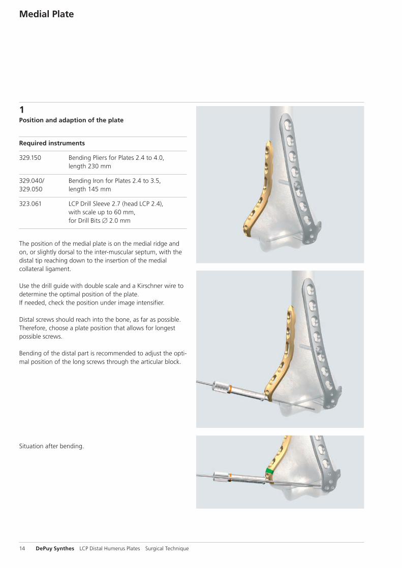
1Position and adaption of the plate
Required instruments
329.150 Bending Pliers for Plates 2.4 to 4.0, length 230 mm
329.040/ Bending Iron for Plates 2.4 to 3.5, 329.050 length 145 mm
323.061 LCP Drill Sleeve 2.7 (head LCP 2.4), with scale up to 60 mm, for Drill Bits B 2.0 mm
The position of the medial plate is on the medial ridge and on, or slightly dorsal to the inter-muscular septum, with the distal tip reaching down to the insertion of the medial collateral ligament.
Use the drill guide with double scale and a Kirschner wire to determine the optimal position of the plate.If needed, check the position under image intensifier.
Distal screws should reach into the bone, as far as possible. Therefore, choose a plate position that allows for longest possible screws.
Bending of the distal part is recommended to adjust the opti-mal position of the long screws through the articular block.
Situation after bending.
LCP Distal Humerus Plates Surgical Technique DePuy Synthes 15
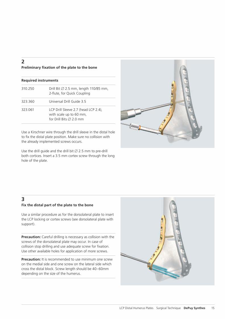
2Preliminary fixation of the plate to the bone
Required instruments
310.250 Drill Bit B 2.5 mm, length 110/85 mm, 2-flute, for Quick Coupling
323.360 Universal Drill Guide 3.5
323.061 LCP Drill Sleeve 2.7 (head LCP 2.4), with scale up to 60 mm, for Drill Bits B 2.0 mm
Use a Kirschner wire through the drill sleeve in the distal hole to fix the distal plate position. Make sure no collision with the already implemented screws occurs.
Use the drill guide and the drill bit B 2.5 mm to pre-drill both cortices. Insert a 3.5 mm cortex screw through the long hole of the plate.
3Fix the distal part of the plate to the bone
Use a similar procedure as for the dorsolateral plate to insert the LCP locking or cortex screws (see dorsolateral plate with support).
Precaution: Careful drilling is necessary as collision with the screws of the dorsolateral plate may occur. In case of collision stop drilling and use adequate screw for fixation. Use other available holes for application of more screws.
Precaution: It is recommended to use minimum one screw on the medial side and one screw on the lateral side which cross the distal block. Screw length should be 40 –60mm depending on the size of the humerus.
16 DePuy Synthes LCP Distal Humerus Plates Surgical Technique
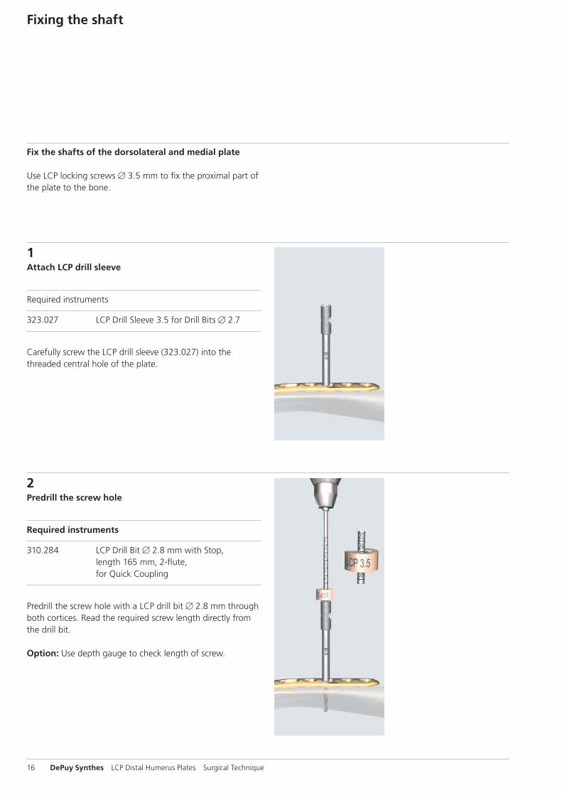
1Attach LCP drill sleeve
Required instruments
323.027 LCP Drill Sleeve 3.5 for Drill Bits B 2.7
Carefully screw the LCP drill sleeve (323.027) into the threaded central hole of the plate.
2Predrill the screw hole
Required instruments
310.284 LCP Drill Bit B 2.8 mm with Stop, length 165 mm, 2-flute, for Quick Coupling
Predrill the screw hole with a LCP drill bit B 2.8 mm through both cortices. Read the required screw length directly from the drill bit.
Option: Use depth gauge to check length of screw.
Fixing the shaft
Fix the shafts of the dorsolateral and medial plate
Use LCP locking screws B 3.5 mm to fix the proximal part of the plate to the bone.
LCP Distal Humerus Plates Surgical Technique DePuy Synthes 17
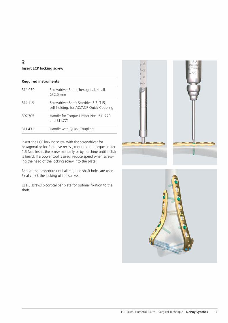
3Insert LCP locking screw
Required instruments
314.030 Screwdriver Shaft, hexagonal, small, B 2.5 mm
314.116 Screwdriver Shaft Stardrive 3.5, T15, self-holding, for AO/ASIF Quick Coupling
397.705 Handle for Torque Limiter Nos. 511.770 and 511.771
311.431 Handle with Quick Coupling
Insert the LCP locking screw with the screwdriver for hexagonal or for Stardrive recess, mounted on torque limiter 1.5 Nm. Insert the screw manually or by machine until a click is heard. If a power tool is used, reduce speed when screw-ing the head of the locking screw into the plate.
Repeat the procedure until all required shaft holes are used. Final check the locking of the screws.
Use 3 screws bicortical per plate for optimal fixation to the shaft.
18 DePuy Synthes LCP Distal Humerus Plates Surgical Technique
Option: Dorsolateral plate without support
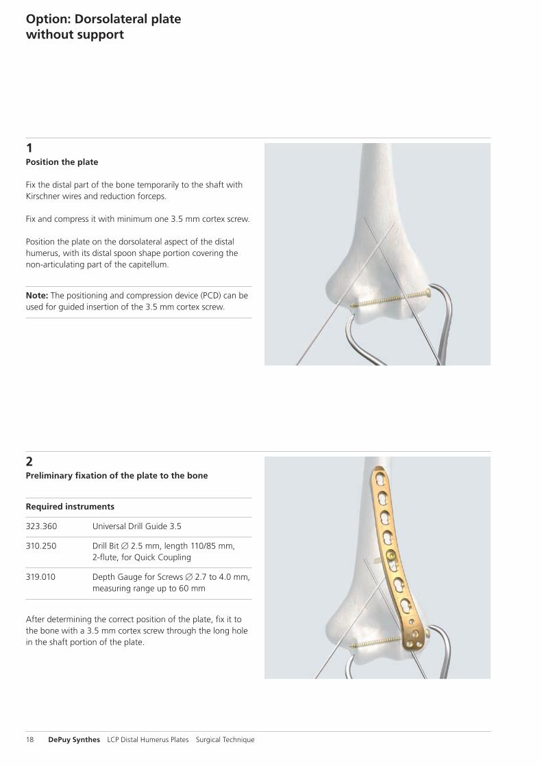
1Position the plate
Fix the distal part of the bone temporarily to the shaft with Kirschner wires and reduction forceps.
Fix and compress it with minimum one 3.5 mm cortex screw.
Position the plate on the dorsolateral aspect of the distal humerus, with its distal spoon shape portion covering the non-articulating part of the capitellum.
Note: The positioning and compression device (PCD) can be used for guided insertion of the 3.5 mm cortex screw.
2Preliminary fixation of the plate to the bone
Required instruments
323.360 Universal Drill Guide 3.5
310.250 Drill Bit B 2.5 mm, length 110/85 mm, 2-flute, for Quick Coupling
319.010 Depth Gauge for Screws B 2.7 to 4.0 mm, measuring range up to 60 mm
After determining the correct position of the plate, fix it to the bone with a 3.5 mm cortex screw through the long hole in the shaft portion of the plate.
LCP Distal Humerus Plates Surgical Technique DePuy Synthes 19
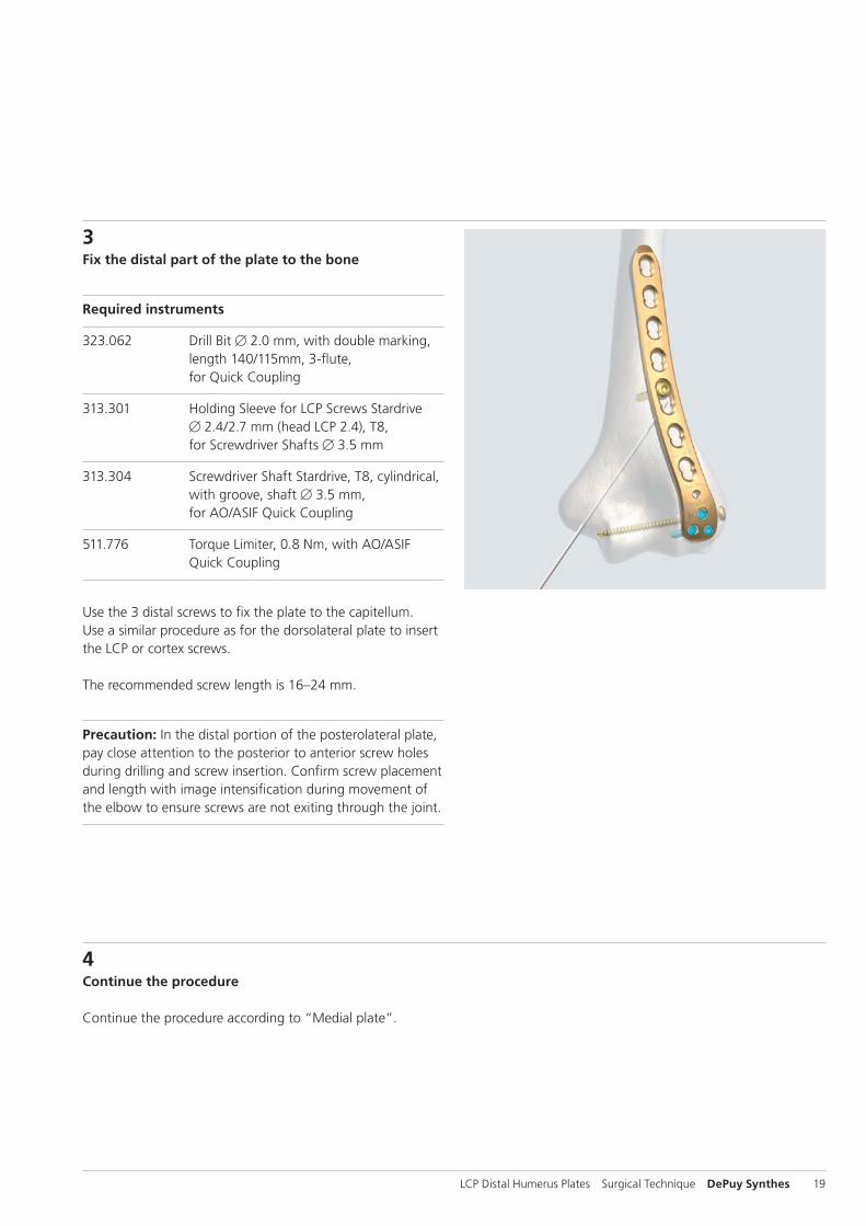
3Fix the distal part of the plate to the bone
Required instruments
323.062 Drill Bit B 2.0 mm, with double marking, length 140/115mm, 3-flute, for Quick Coupling
313.301 Holding Sleeve for LCP Screws Stardrive B 2.4/2.7 mm (head LCP 2.4), T8, for Screwdriver Shafts B 3.5 mm
313.304 Screwdriver Shaft Stardrive, T8, cylindrical, with groove, shaft B 3.5 mm, for AO/ASIF Quick Coupling
511.776 Torque Limiter, 0.8 Nm, with AO/ASIF Quick Coupling
Use the 3 distal screws to fix the plate to the capitellum. Use a similar procedure as for the dorsolateral plate to insert the LCP or cortex screws.
The recommended screw length is 16–24 mm.
Precaution: In the distal portion of the posterolateral plate, pay close attention to the posterior to anterior screw holes during drilling and screw insertion. Confirm screw placement and length with image intensification during movement of the elbow to ensure screws are not exiting through the joint.
4Continue the procedure
Continue the procedure according to “Medial plate”.
20 DePuy Synthes LCP Distal Humerus Plates Surgical Technique
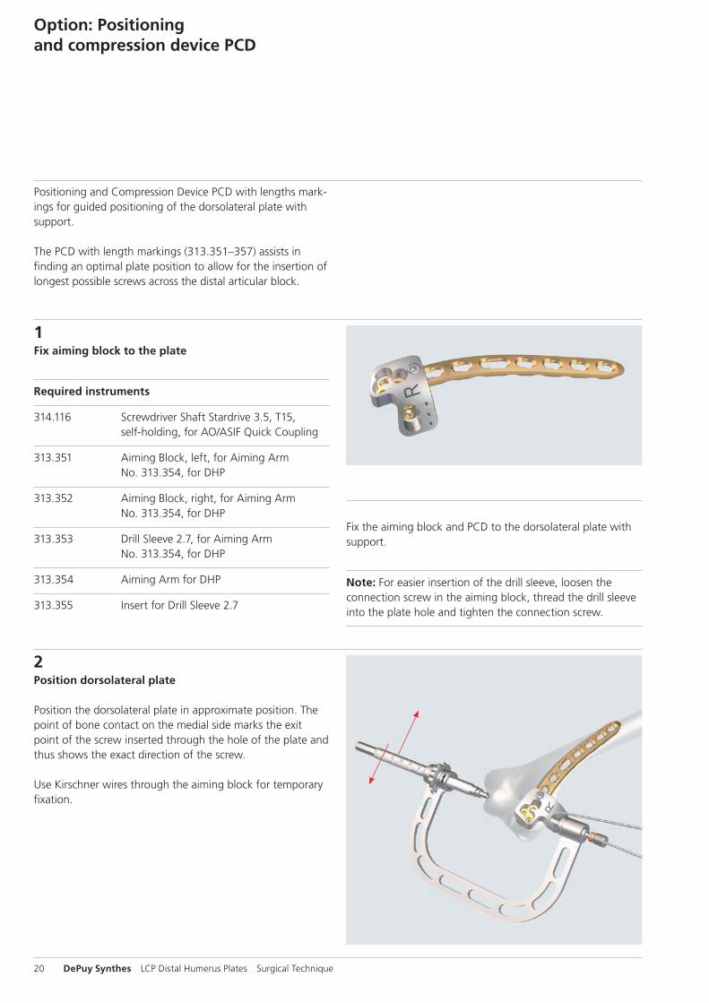
Option: Positioning and compression device PCD
1Fix aiming block to the plate
Required instruments
314.116 Screwdriver Shaft Stardrive 3.5, T15, self-holding, for AO/ASIF Quick Coupling
313.351 Aiming Block, left, for Aiming Arm No. 313.354, for DHP
313.352 Aiming Block, right, for Aiming Arm No. 313.354, for DHP
313.353 Drill Sleeve 2.7, for Aiming Arm No. 313.354, for DHP
313.354 Aiming Arm for DHP
313.355 Insert for Drill Sleeve 2.7
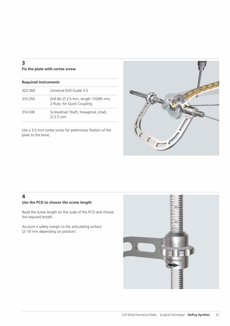
2Position dorsolateral plate
Position the dorsolateral plate in approximate position. The point of bone contact on the medial side marks the exit point of the screw inserted through the hole of the plate and thus shows the exact direction of the screw.
Use Kirschner wires through the aiming block for temporary fixation.
Positioning and Compression Device PCD with lengths mark-ings for guided positioning of the dorsolateral plate with support.
The PCD with length markings (313.351–357) assists in finding an optimal plate position to allow for the insertion of longest possible screws across the distal articular block.
Fix the aiming block and PCD to the dorsolateral plate with support.
Note: For easier insertion of the drill sleeve, loosen the connection screw in the aiming block, thread the drill sleeve into the plate hole and tighten the connection screw.
LCP Distal Humerus Plates Surgical Technique DePuy Synthes 21
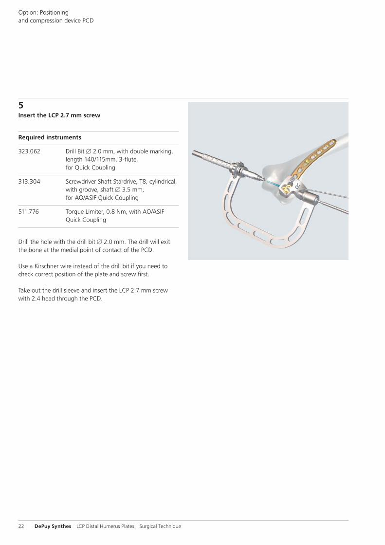
3Fix the plate with cortex screw
Required instruments
323.360 Universal Drill Guide 3.5
310.250 Drill Bit B 2.5 mm, length 110/85 mm, 2-flute, for Quick Coupling
314.030 Screwdriver Shaft, hexagonal, small, B 2.5 mm
Use a 3.5 mm cortex screw for preliminary fixation of the plate to the bone.
4Use the PCD to choose the screw length
Read the screw length on the scale of the PCD and choose the required length.
Account a safety margin to the articulating surface (2–10 mm depending on position).
22 DePuy Synthes LCP Distal Humerus Plates Surgical Technique
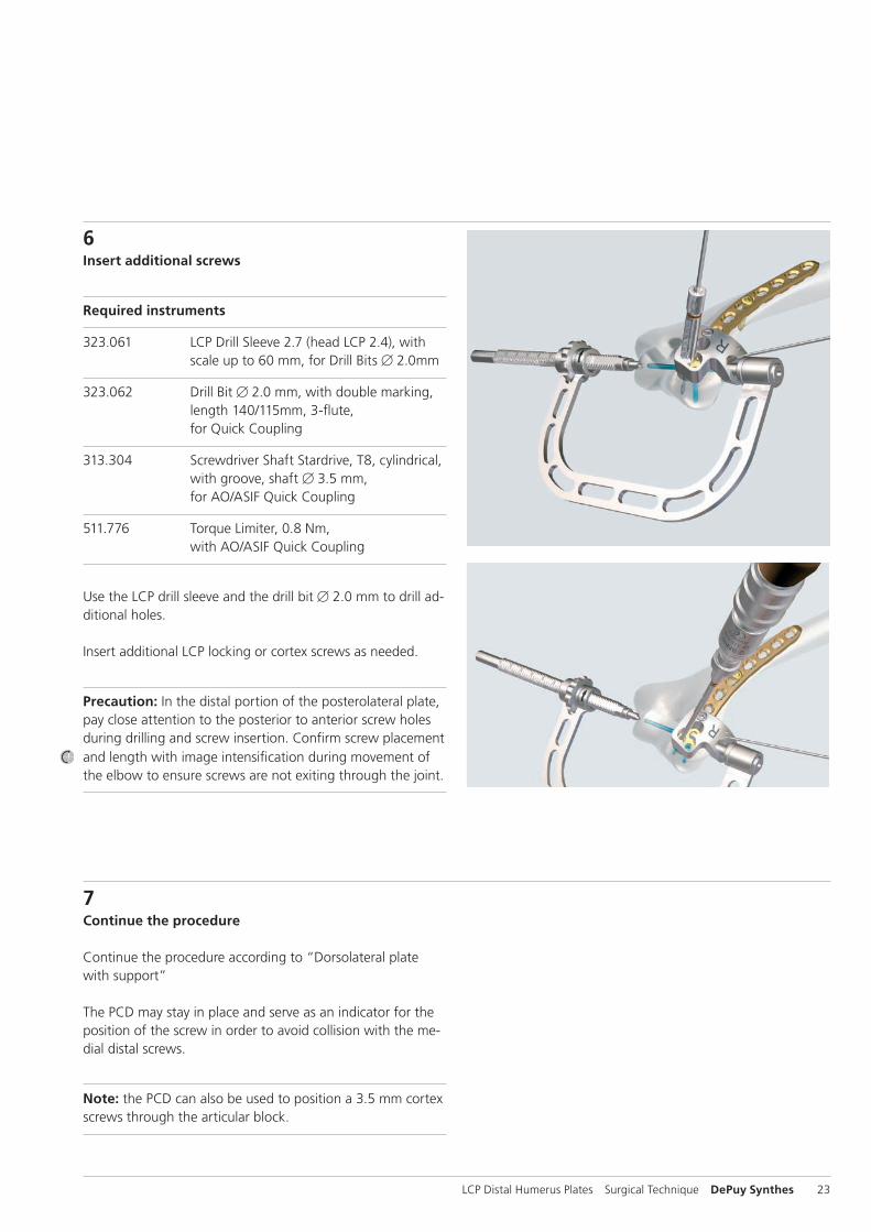
5Insert the LCP 2.7 mm screw
Required instruments
323.062 Drill Bit B 2.0 mm, with double marking, length 140/115mm, 3-flute, for Quick Coupling
313.304 Screwdriver Shaft Stardrive, T8, cylindrical, with groove, shaft B 3.5 mm, for AO/ASIF Quick Coupling
511.776 Torque Limiter, 0.8 Nm, with AO/ASIF Quick Coupling
Drill the hole with the drill bit B 2.0 mm. The drill will exit the bone at the medial point of contact of the PCD.
Use a Kirschner wire instead of the drill bit if you need to check correct position of the plate and screw first.
Take out the drill sleeve and insert the LCP 2.7 mm screw with 2.4 head through the PCD.
Option: Positioning and compression device PCD
LCP Distal Humerus Plates Surgical Technique DePuy Synthes 23
6Insert additional screws
Required instruments
323.061 LCP Drill Sleeve 2.7 (head LCP 2.4), with scale up to 60 mm, for Drill Bits B 2.0mm
323.062 Drill Bit B 2.0 mm, with double marking, length 140/115mm, 3-flute, for Quick Coupling
313.304 Screwdriver Shaft Stardrive, T8, cylindrical, with groove, shaft B 3.5 mm, for AO/ASIF Quick Coupling
511.776 Torque Limiter, 0.8 Nm, with AO/ASIF Quick Coupling
Use the LCP drill sleeve and the drill bit B 2.0 mm to drill ad-ditional holes.
Insert additional LCP locking or cortex screws as needed.
Precaution: In the distal portion of the posterolateral plate, pay close attention to the posterior to anterior screw holes during drilling and screw insertion. Confirm screw placement and length with image intensification during movement of the elbow to ensure screws are not exiting through the joint.
7Continue the procedure
Continue the procedure according to “Dorsolateral plate with support” The PCD may stay in place and serve as an indicator for the position of the screw in order to avoid collision with the me-dial distal screws.
Note: the PCD can also be used to position a 3.5 mm cortex screws through the articular block.
24 DePuy Synthes LCP Distal Humerus Plates Surgical Technique
Option: LCP Metaphyseal Plate 3.5 for distal medial humerus
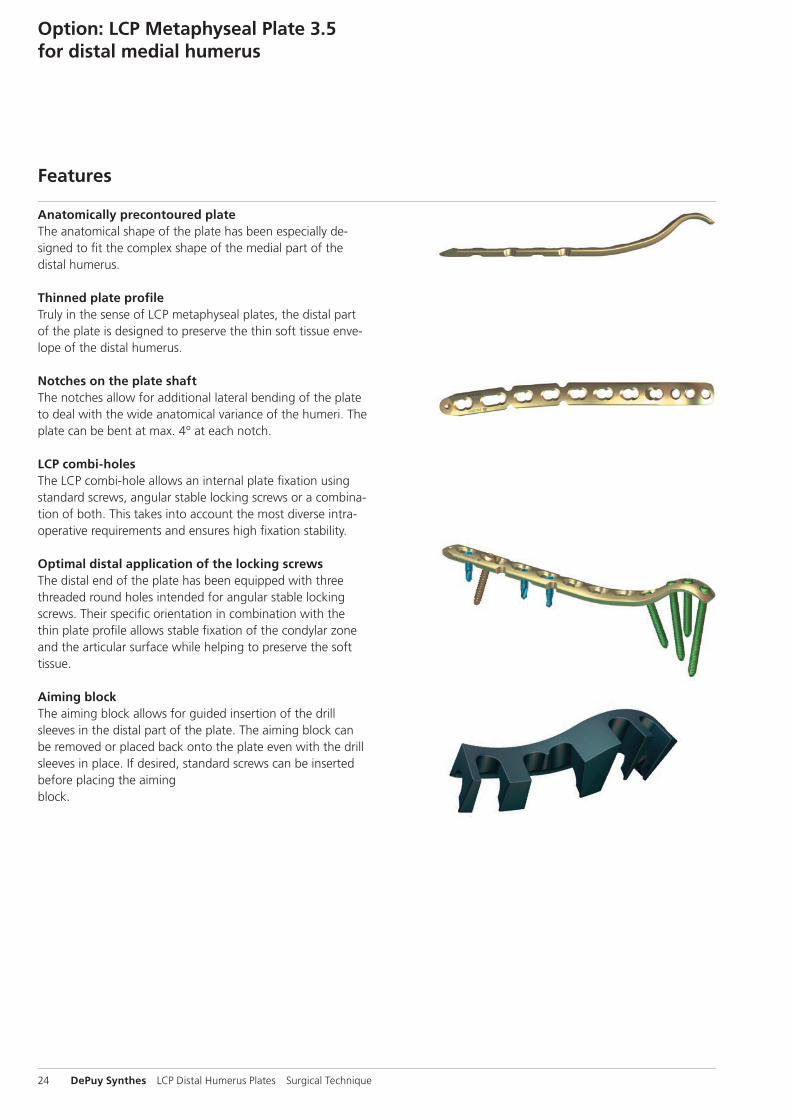
Anatomically precontoured plateThe anatomical shape of the plate has been especially de-signed to fi t the complex shape of the medial part of the distal humerus.
Thinned plate profileTruly in the sense of LCP metaphyseal plates, the distal part of the plate is designed to preserve the thin soft tissue enve-lope of the distal humerus.
Notches on the plate shaftThe notches allow for additional lateral bending of the plate to deal with the wide anatomical variance of the humeri. The plate can be bent at max. 4° at each notch.
LCP combi-holesThe LCP combi-hole allows an internal plate fi xation using standard screws, angular stable locking screws or a combina-tion of both. This takes into account the most diverse intra-operative requirements and ensures high fi xation stability.
Optimal distal application of the locking screwsThe distal end of the plate has been equipped with three threaded round holes intended for angular stable locking screws. Their specifi c orientation in combination with the thin plate profi le allows stable fi xation of the condylar zone and the articular surface while helping to preserve the soft tissue.
Aiming blockThe aiming block allows for guided insertion of the drill sleeves in the distal part of the plate. The aiming block can be removed or placed back onto the plate even with the drill sleeves in place. If desired, standard screws can be inserted before placing the aimingblock.
Features
LCP Distal Humerus Plates Surgical Technique DePuy Synthes 25
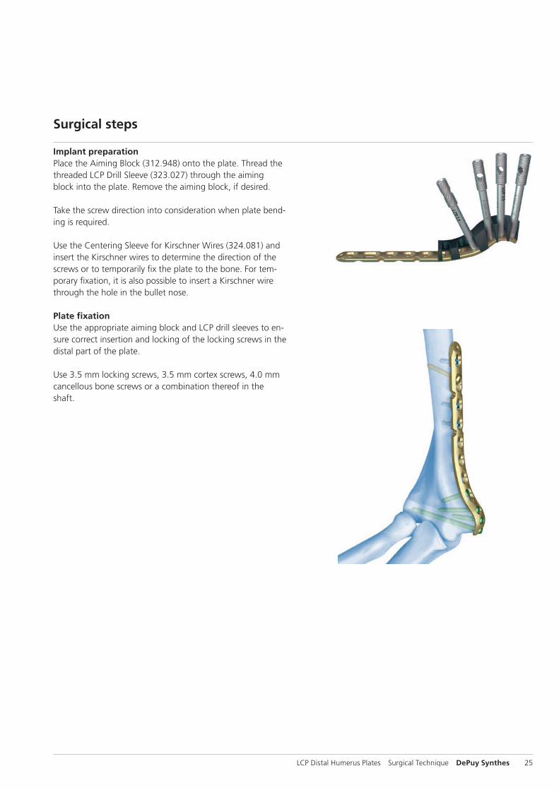
Implant preparationPlace the Aiming Block (312.948) onto the plate. Thread the threaded LCP Drill Sleeve (323.027) through the aiming block into the plate. Remove the aiming block, if desired.
Take the screw direction into consideration when plate bend-ing is required.
Use the Centering Sleeve for Kirschner Wires (324.081) and insert the Kirschner wires to determine the direction of the screws or to temporarily fi x the plate to the bone. For tem-porary fi xation, it is also possible to insert a Kirschner wire through the hole in the bullet nose.
Plate fixationUse the appropriate aiming block and LCP drill sleeves to en-sure correct insertion and locking of the locking screws in the distal part of the plate.
Use 3.5 mm locking screws, 3.5 mm cortex screws, 4.0 mm cancellous bone screws or a combination thereof in the shaft.
Surgical steps
26 DePuy Synthes LCP Distal Humerus Plates Surgical Technique
Implant removal
Implant removal
Required instruments
311.440 T-Handle with Quick-Coupling
314.030 Screwdriver Shaft, hexagonal, small, B 2.5 mm
314.116 Screwdriver Shaft Stardrive 3.5, T15, self-holding, for AO/ASIF Quick Coupling
309.520 Extraction Screw, conical, for Screws B 2.7, 3.5 and 4.0 mm
309.521 Extraction Screw for Screws B 3.5 mm
309.510 Extraction Screw, conical, for Screws B 1.5 and 2.0 mm
Implant removal Unlock all screws from the plate, then remove the screws completely from the bone. This prevents simultaneous rota-tion of the plate when unlocking the last locking screw. If a screw cannot be removed with the screwdriver (e.g. if the hexagonal or Stardrive recess of the locking screw is dam-aged or if the screw is stuck in the plate), use the T-Handle with Quick-Coupling (311.440) to insert the conical Ex-traction Screw (309.520 or 309.521) into the screw head, and unscrew the screw in a counter-clockwise direction.
LCP Distal Humerus Plates Surgical Technique DePuy Synthes 27
Implants
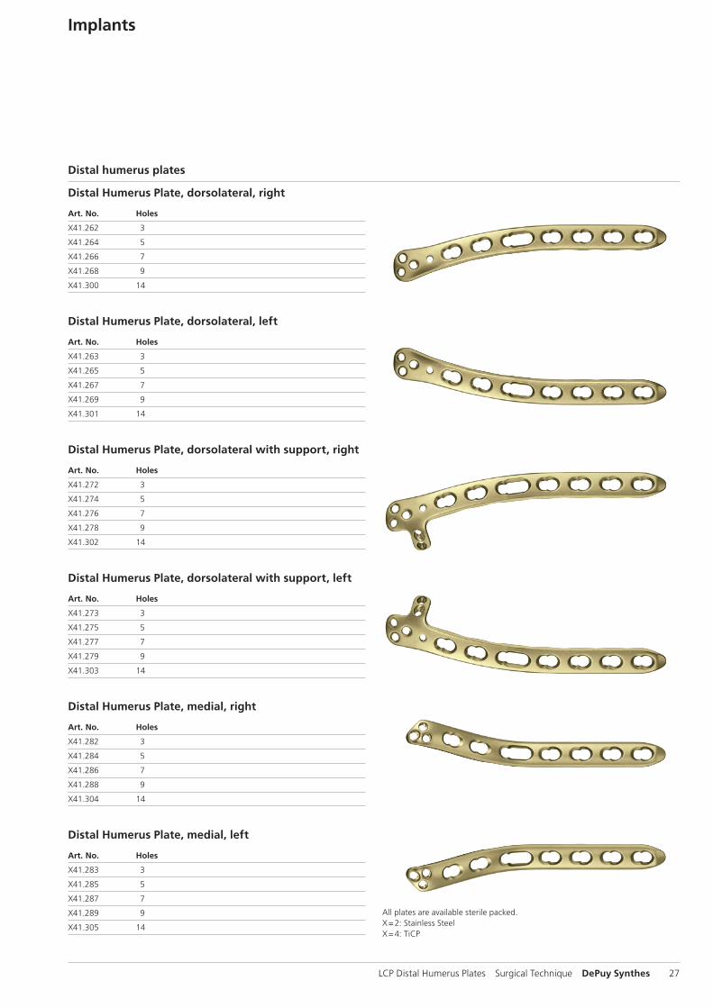
Distal Humerus Plate, dorsolateral, right
Art. No. Holes
X41.262 3
X41.264 5
X41.266 7
X41.268 9
X41.300 14
Distal Humerus Plate, dorsolateral, left
Art. No. Holes
X41.263 3
X41.265 5
X41.267 7
X41.269 9
X41.301 14
Distal Humerus Plate, dorsolateral with support, right
Art. No. Holes
X41.272 3
X41.274 5
X41.276 7
X41.278 9
X41.302 14
Distal Humerus Plate, dorsolateral with support, left
Art. No. Holes
X41.273 3
X41.275 5
X41.277 7
X41.279 9
X41.303 14
Distal Humerus Plate, medial, right
Art. No. Holes
X41.282 3
X41.284 5
X41.286 7
X41.288 9
X41.304 14
Distal Humerus Plate, medial, left
Art. No. Holes
X41.283 3
X41.285 5
X41.287 7
X41.289 9
X41.305 14
All plates are available sterile packed.X = 2: Stainless Steel X = 4: TiCP
Distal humerus plates
28 DePuy Synthes LCP Distal Humerus Plates Surgical Technique
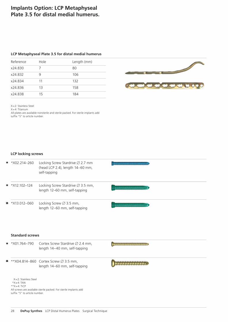
Implants Option: LCP Metaphyseal Plate 3.5 for distal medial humerus.
*X02.214–260 Locking Screw Stardrive B 2.7 mm (head LCP 2.4), length 14–60 mm, self-tapping
*X12.102–124 Locking Screw Stardrive B 3.5 mm, length 12–60 mm, self-tapping
*X13.012–060 Locking Screw B 3.5 mm, length 12–60 mm, self-tapping
Reference Hole Length (mm)
x24.830 7 80
x24.832 9 106
x24.834 11 132
x24.836 13 158
x24.838 15 184
X = 2: Stainless Steel X = 4: Titanium All plates are available nonsterile and sterile packed. For sterile implants add suffix “S” to article number.
Standard screws
*X01.764–790 Cortex Screw Stardrive B 2.4 mm, length 14–40 mm, self-tapping
**X04.814–860 Cortex Screw B 3.5 mm, length 14–60 mm, self-tapping
X = 2: Stainless Steel *X = 4: TAN**X = 4: TiCPAll screws are available sterile packed. For sterile implants add suffix “S” to article number.
LCP locking screws
LCP Metaphyseal Plate 3.5 for distal medial humerus
LCP Distal Humerus Plates Surgical Technique DePuy Synthes 29
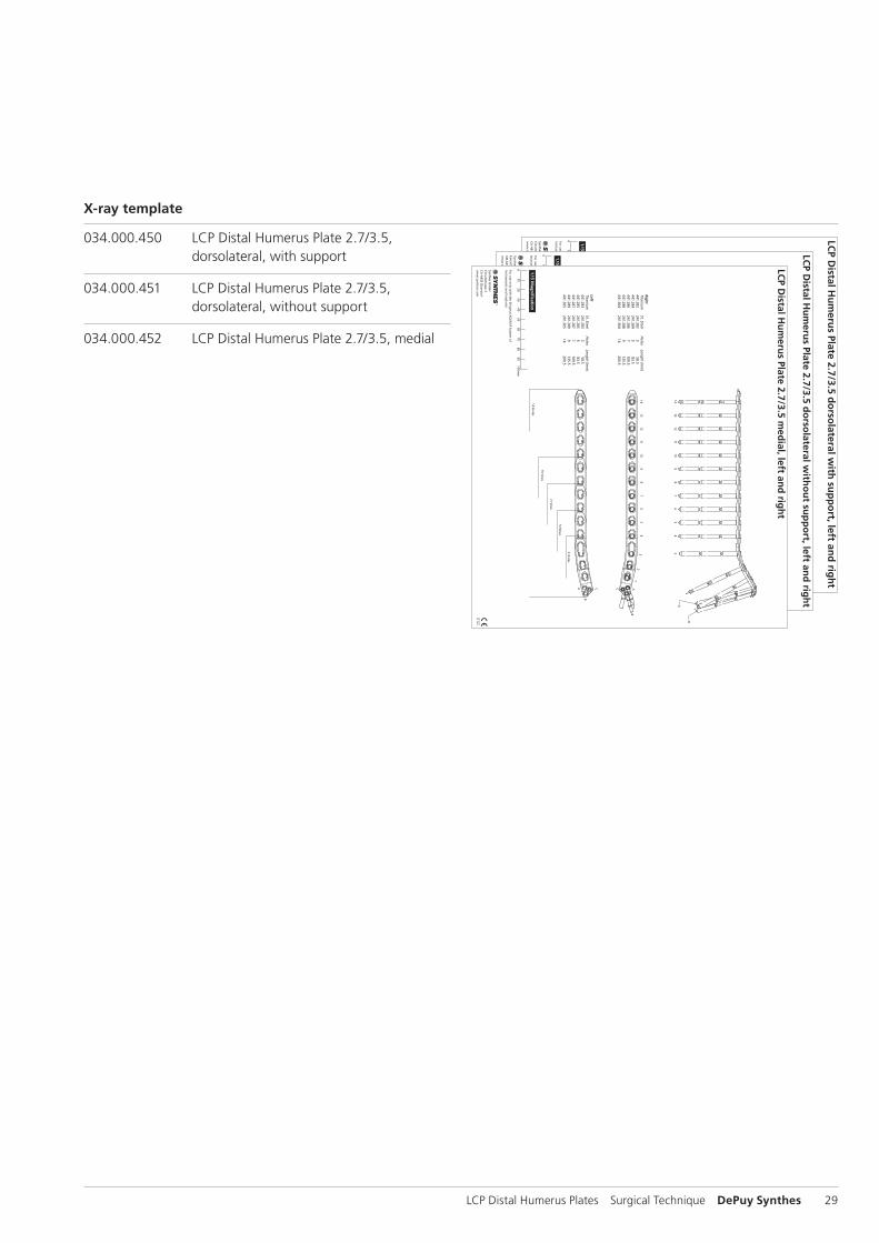
034.000.450 LCP Distal Humerus Plate 2.7/3.5, dorsolateral, with support
034.000.451 LCP Distal Humerus Plate 2.7/3.5, dorsolateral, without support
034.000.452 LCP Distal Humerus Plate 2.7/3.5, medial
X-ray template
30 DePuy Synthes LCP Distal Humerus Plates Surgical Technique
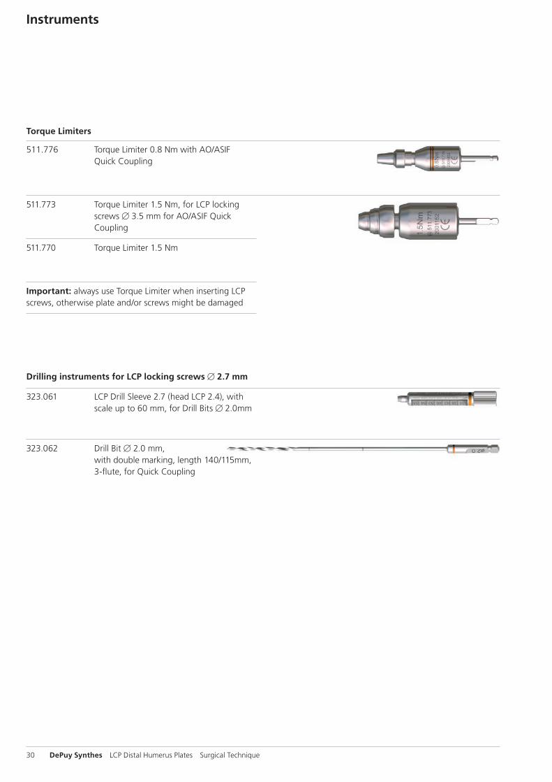
Instruments
511.776 Torque Limiter 0.8 Nm with AO/ASIF Quick Coupling
511.773 Torque Limiter 1.5 Nm, for LCP locking screws B 3.5 mm for AO/ASIF Quick Coupling
511.770 Torque Limiter 1.5 Nm
Important: always use Torque Limiter when inserting LCP screws, otherwise plate and/or screws might be damaged
Drilling instruments for LCP locking screws B 2.7 mm
323.061 LCP Drill Sleeve 2.7 (head LCP 2.4), with scale up to 60 mm, for Drill Bits B 2.0mm
323.062 Drill Bit B 2.0 mm, with double marking, length 140/115mm, 3-flute, for Quick Coupling
Torque Limiters
LCP Distal Humerus Plates Surgical Technique DePuy Synthes 31
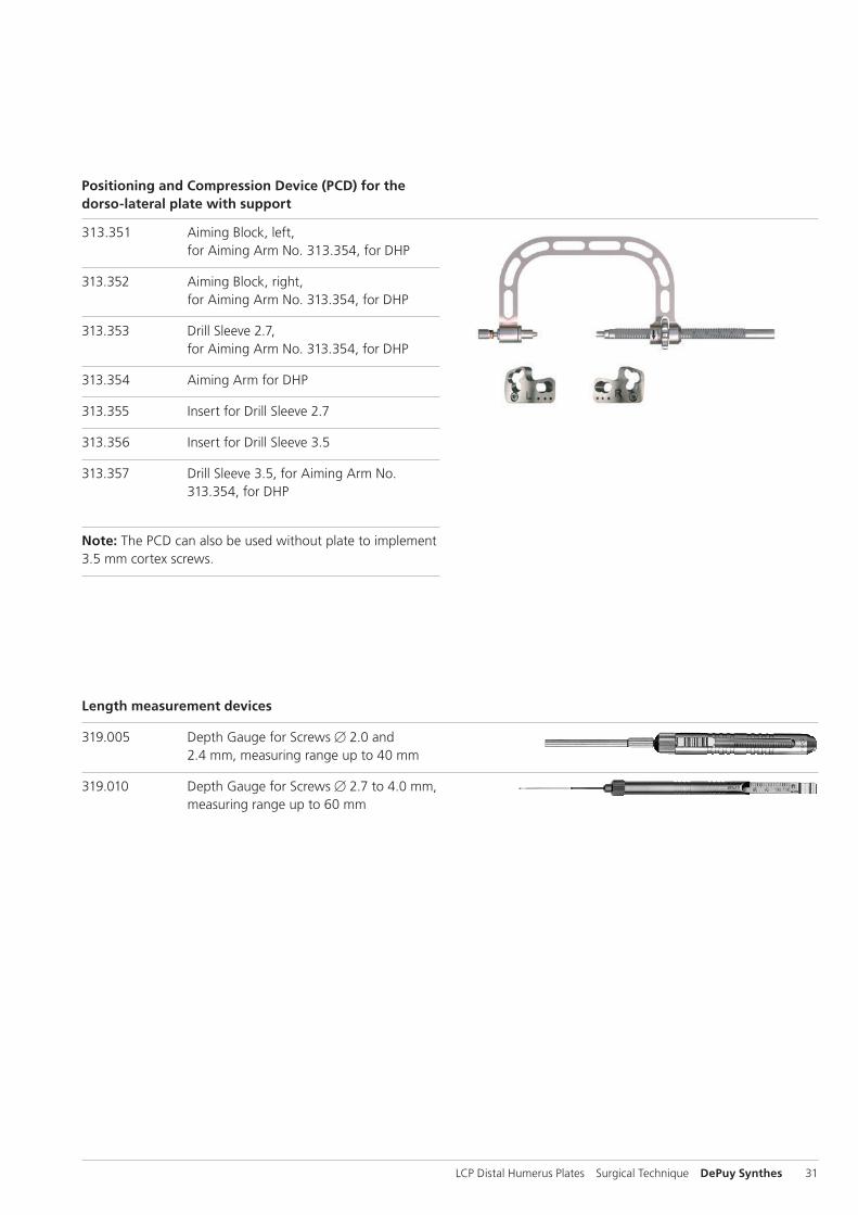
313.351 Aiming Block, left, for Aiming Arm No. 313.354, for DHP
313.352 Aiming Block, right, for Aiming Arm No. 313.354, for DHP
313.353 Drill Sleeve 2.7, for Aiming Arm No. 313.354, for DHP
313.354 Aiming Arm for DHP
313.355 Insert for Drill Sleeve 2.7
313.356 Insert for Drill Sleeve 3.5
313.357 Drill Sleeve 3.5, for Aiming Arm No. 313.354, for DHP
Note: The PCD can also be used without plate to implement 3.5 mm cortex screws.
Length measurement devices
319.005 Depth Gauge for Screws B 2.0 and 2.4 mm, measuring range up to 40 mm
319.010 Depth Gauge for Screws B 2.7 to 4.0 mm, measuring range up to 60 mm
Positioning and Compression Device (PCD) for the dorso-lateral plate with support
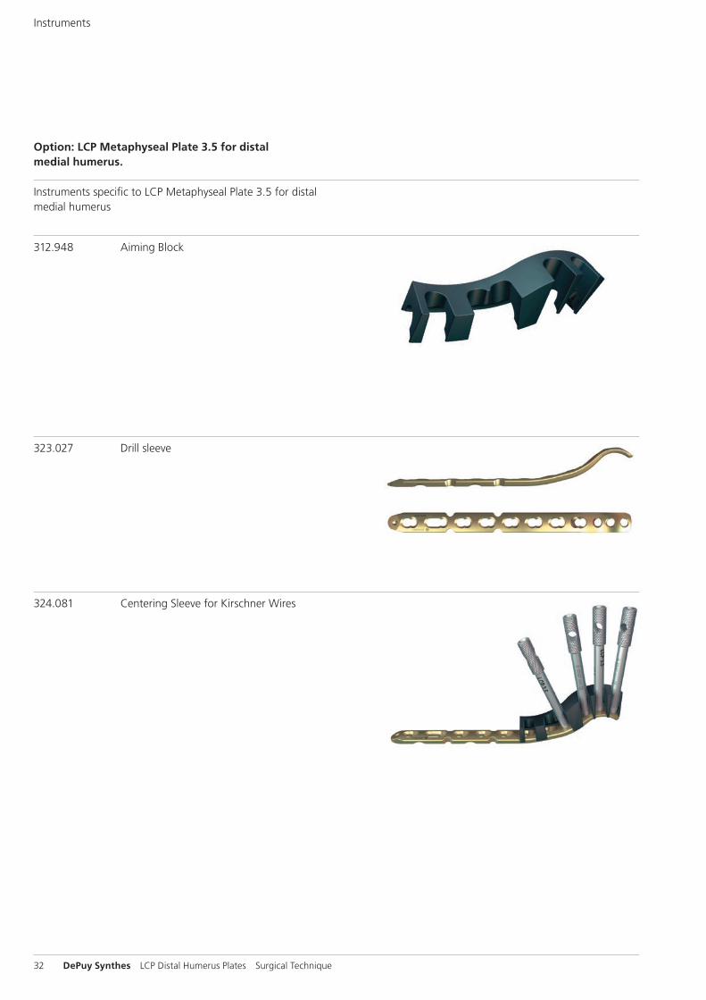
323.027 Drill sleeve
32 DePuy Synthes LCP Distal Humerus Plates Surgical Technique
Instruments specifi c to LCP Metaphyseal Plate 3.5 for distal medial humerus
312.948 Aiming Block
Instruments
324.081 Centering Sleeve for Kirschner Wires
Option: LCP Metaphyseal Plate 3.5 for distal medial humerus.
LCP Distal Humerus Plates Surgical Technique DePuy Synthes 33
MRI Information
Torque, Displacement and Image Artifacts according to ASTM F 2213-06, ASTM F 2052-06e1 and ASTM F2119-07Non-clinical testing of worst case scenario in a 3 T MRI system did not reveal any relevant torque or displacement of the construct for an experimentally measured local spatial gradient of the magnetic field of 3.69 T/m. The largest image artifact extended approximately 169 mm from the construct when scanned using the Gradient Echo (GE). Testing was conducted on a 3 T MRI system.
Radio-Frequency-(RF-)induced heating according to ASTM F2182-11aNon-clinical electromagnetic and thermal testing of worst case scenario lead to peak temperature rise of 9.5 °C with an average temperature rise of 6.6 °C (1.5 T) and a peak temperature rise of 5.9 °C (3 T) under MRI Conditions using RF Coils [whole body averaged specific absorption rate (SAR) of 2 W/kg for 6 minutes (1.5 T) and for 15 minutes (3 T)].
Precautions: The above mentioned test relies on non-clini-cal testing. The actual temperature rise in the patient will depend on a variety of factors beyond the SAR and time of RF application. Thus, it is recommended to pay particular attention to the following points: – It is recommended to thoroughly monitor patients under-
going MR scanning for perceived temperature and/or pain sensations.
– Patients with impaired thermo regulation or temperature sensation should be excluded from MR scanning proce-dures.
– Generally it is recommended to use a MR system with low field strength in the presence of conductive implants. The employed specific absorption rate (SAR) should be reduced as far as possible.
– Using the ventilation system may further contribute to reduce temperature increase in the body.

0123
Synthes GmbHEimattstrasse 34436 OberdorfSwitzerlandTel: +41 61 965 61 11Fax: +41 61 965 66 00www.depuysynthes.com
Not all products are currently available in all markets.
This publication is not intended for distribution in the USA.
All surgical techniques are available as PDF files at www.depuysynthes.com/ifu ©
DeP
uy S
ynth
es T
raum
a, a
div
isio
n of
Syn
thes
Gm
bH. 2
016.
A
ll rig
hts
rese
rved
. 03
6.0
0.4
61
DSE
M/T
RM
/081
5/0
44
4(1
) 03
/16