phase directional overcurrent relays · type jbc relays are single phase, directional overcurrent...
TRANSCRIPT
INSTRUCTIONS GEI-50275C
SUPERSEDES GEI-502758
PHASE DIRECTIONAL OVERCURRENT RELAYS
Types
JBCS1E JBCS4E JBCS2E JBC77E JBCS3E JBC78E
GENERAL fj ELECTRIC
QEI-50275 Phase Directional Overcurrent Relay Type JBC
I NSTANTANE- BARREL
OUS OVER- CONTACT
CURRENT UNIT
TAP PLUG TAP BLOCK
TIME OVER-CURRENT
SEAL-IN UNIT UNIT FOR lI:
TIME OVER- TAP SCREW CI)
CURRENT > UNIT
SEAL-IN .... UNIT FOR c INSTANTANE- 0 ..
LOW GRADIENT OUS OVER- u.. CONTACT CURRENT UNIT -In (STATIONARY DRAG MAGNET M
(¥) M
LOW GRADIENT N
CONTACT 0 QO
(MOVING) -P Ii,
u..
:k CRADLE CI)
>
Front View ... <II CI) = -N
(¥)
M (W) N 0 QO
TIME OVER-CURRENT . MAGNET AND
c:n
COIL ASSEMBLY u..
Rear View
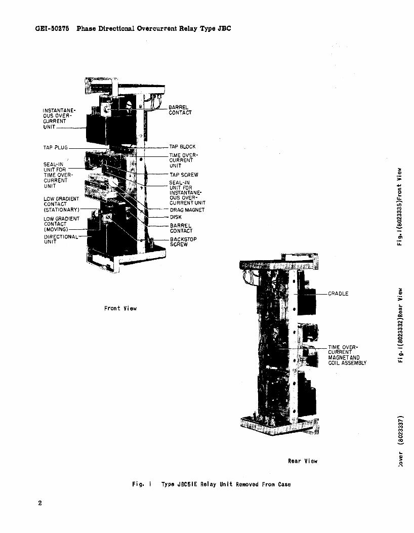
Fig. I Type JBC51E Relay Unit Removed From Case
2

PHASE DIRECTIONAL O'VERCURRENT RELAY
TYPE JBC INTRODUCTION
Type JBC relays are single phase, directional overcurrent relays used primarily for the protection of feeders and transmission lines. They are available with inverse, very inverse or extremely inverse time characteristics.
They consist of three units, an instantaneous overcurrent unit (top) of the induction-cup type, a time over current unit (middle) of the inductiondisk' type, and an instantaneous power-directional unit (bottom) of the induction-cup type. The directional unit is potential polarized and, by means of its closing contacts, directionally controls the operation of both the time overcurrent and instantaneous overcurrent units.
APPLICATION Type JBC relays are generally applied for
phase fault protection of a single line. Since fault currents are usually highly lagging, the quadrature (90 degree) connection, shown in Fig. 9, provides the most reliable potential for the directional unit. At the relay terminals, the current, at unity powerfactor load, leads the potential by 90 degrees. Since the relay has an approximate maximum torque angle characteristic of 45 degrees lead (current leads voltage), the directional unit will develop maximum operating torque when the fault current lags its unity power-factor position by about 45 degrees.
The differences between the various models covered by this instruction book are shown in Table 1. Inverse time relays should be used on systems where the fault current flowing through a given relay is influenced largely by the system generating capacity at the time of the fault. Very inverse time and extremely inverse time relays should be used in cases where the fault current magnitude is dependent mainly upon the location of the fault in relation to the relay, and only slightly or not at all upon the system generating setup. The reason for this is that relays must be set to be selective with maximum fault current flowing. For fault currents below this value, the operating time becomes greater as the current is decreased. If there is a wide range in generating capacity, together with variation in short-circuit current with fault pOSition, the operating time with minimum fault current may be exceedingly long with very inverse time relays and even longer with extremely inverse time relays. For such cases, the inverse time relay is more applicable.
. The choice between very inverse and extremely inverse time relays is more limited than between them and the inverse time relay as they are more nearly alike in their time-current characteristic
curves. For grading with fuses the extremely inverse time relay should be chosen as the timecurrent curves more nearly match the fuse curve. Another advantage of the extremely inverse relay is that it is better suited than both the inverse and very inverse relays for picking up cold load. For any given cold load pick-up capability, the resulting settings will provide faster protection at high fault currents with the extremely inverse relay than with the less inverse relays.
* TABLE I
Relay Time Circuit Internal Closing Connec-Model Characteristics Contacts tions
JBC51E Inverse One Fig. 2 JBC52E Inverse Two Fig. 3 JBC53E Very Inverse One Fig. 4 JBC54E Very Inverse Two Fig. 5 JBC77E Extr. Inverse One Fig. 6 JBC78E Extr. Inverse Two Fig. 7
OPERATING ,CHARACTERISTICS PICKUP
A t the maximum torque angle, the directional unit will pick up at one percent of rated voltage with 2 amperes for relays with 1.5/6 ampere time overcurrent units, and 4 amperes for relays with 4/16 ampere time overcurrent units.
The maximum operating current required to close the time overcurrent unit contacts, at any time-dial po 'tion, will be within five percent of the tap plug Sl Cing.
'The pickup ·of the instantaneous overcurrent unit can be adjusted over a four-to-one range as indicated in Table m. RESET
The minimum percentage of mmlmum closing current at which the time over cur rent unit will reset is 90% for inverse-time relays and 85% for very inverse-time and extremely inverse-time relays. When the relay is de-energized, the time required for the disk to completely reset to the number 10 time dial position is approximately 6 seconds for inverse time relays and 60 seconds for very inversetime and extremely inverse-time relays.
OPERATING TIME The time curves for the directional unit are
shown in Fig. 16 and Fig. 17~
These instructions do not purport to cover a~~ detai~s or variations in equipment nor to provide for every possible contingency to be met in connection with installation, operation or maintenance. Should further information be desired or should particular problems arise which are not covered sufficiently for the purchaser's purposes, the matter should be referred to the General Electric Company.
To the extent required the products described herein meet applicable ANSI, IEEE and NE~ standards; 3 but no such assurance is given with respect to local codes and ordinances because they vary greatly.

GEI-50275 Phase Directional Overcurrent Relay Type JBC
The time curves of the time over current unit are shown in Figs. 18, 19 and 20 respectively for inverse-time, very inverse-time and extremely inverse-time relays. For the same operating conditions, the relay will operate repeatedly within one or two per cent of the same time. '
The time curves for the instantaneous overcurrent unit are shown in Fig. 15.
RATINGS CURRENT CIRCUITS'
The continuous and short time ratings of the time over current unit operating coil circuit are shown in Table II. These same ratings are applicable to the directional unit operating coil circuit except that its continuous rating is independent of changes in the time overcurrent unit tap setting. Hence, the information associated with the asterisk under Table II does not apply to the directional unit operating coil. Table III shows the ratings of the available ranges of the instantaneous overcurrent unit. Since all operating current circuits are normally connected in series, the operating coil ratings of all three units should be considered in determining the rating of the entire operating circuit.
TAP
TABLE II
RA TINGS OF TIME OVERCURRENT UNIT OPERATING COILS
TAP *CONT. ONE SEC. RANGE RATINGS RATING RATING (AMPS) (AMPS) (AMPS) (AMPS)
1.5/6 1.5,2,2.5,3,4,5,6 5 200
4/16 4,5,6,8,10,12,16 10 220
* Applies to all taps up to and including this value. The continuous rating of higher current taps is the same as tap value.
TABLE III
RA TINGS OF INSTANTANEOUS OVERCURRENT UNIT OPERATING COILS
PICKUP CONTINUOUS ONE SECOND RANGE RATING RATING (AMPS) (AMPS) (AMPS)
2-8 5 160 4-16 5 160
10-40 5 220
20-80 5 220
40-160 5 220
SEAL-IN UNIT The rating and impedance of the seal-in unit
for the 0.2 and 2 ampere taps are given in Table IV. The tap setting used will depend on the current
4
drawn by the trip coil. The current ratings are either AC or DC.
The 0.2 ampere tap is for use with trip coils 'which operate on currents ranging from 0.2 up to 2.0 amperes, at the minimum control voltage. If this tap is used with trip coils requiring more than 2 amperes, there is a possibility that the resistance of 7 ohms will reduce the current to so low a value that the breaker will not be tripped.
The 2 ampere tap should be used with trip coils that take two amperes or more at minimum control voltage, provided the current does not exceed 30 amperes at the maximum control voltage. If the tripping current exceeds 30amperes, the connections should be arranged so that the induction unit contacts will operate an auxiliary relay which in turn energizes the trip coil or coils. On such an application, it may be necessary to connect a loading resistor in parallel with the auxiliary relay coil to allow enough current to operate the target seal-in unit.
TABLE IV
SEAL-IN UNIT RATINGS
2 AMP TAP
Carry-Tripping Duty 30 Amps Carry Continuously 3 Amps DC Resistance 0.13 Ohms Impedance (60 cycles) 0.53 Ohms
CONTACTS
0.2 AMP TAP
3 Amps 0.3 Amps
7 Ohms 52 Ohms
The current-closing rating of the induction unit contacts is 30 amperes for voltages not exceeding 250 volts. Their current-carrying rating is limited by the tap rating of the seal-in unit.
BURDENS
The potential circuit burden of the directional unit at 60 cycles and rated volts is 10 volt-amperes at 0.89 power factor. Table V gives the current circuit burden of the directional unit. Table VI gives the total burden of the time over current unit plus instantaneous overcurrent unit.
TABLE V
nffiECTIONAL UNIT CURRENT CIRCUIT BURDENS AT 60 CYCLES AND 5 AMPERES
TAP IMPED. VOLT- POWER WATTS RANGE (OHMS) AMPERES FACTOR
1.5/6 0.46 12.0 0.52 6.24
4/16 0.13 3.3 0.40 1.32

Phase Directional Overcurrent Relay Type JBC GEI-50275
TABLE VI
BURDENS OF OVERCURRENT UNITS (TIME AND INSTANTANEOUS) AT 60 CYCLES
RANGE BURDENS AT MINIMUM PICKUP OFTIME UNIT OHMS IMPEDANCE AT Time * VA
Character- Time Inst. Eff. Res. React. * Imped. + Volt- Power 3 Times 10 Times At 5 istic (Ohms) (Ohms) (Ohms) Min. P.U. Amps Unit Unit Amps Factor Min. P.U.
Inverse 1.5/6 2-8 1.00 2.70 2.90 6.5 0.35 1.70 1.00 73
4-16 Inverse 1.5/6 10-40 0.96 2.60 2.80 6.3 0.34 1.70 0.97 70
20-40 Inverse 4/16 2-8 0.23 0.41 0.47 7.5 0.49 0.28 0.16 12
Inverse 4/16 4-16 0.18 0.38 0.42 6.7 0.42 0.25 0.15 10.5
invarse 4/16 10-40 0.15 0.37 0.40 6.1 0.38 0.24 0.14 10.0 20-80 Verv 1.5/6 2-8 0.32 0.60
Inver .. ;; 0.68 1.5 0.47 0.64 0.55 17
Very 4-16 1.5/6 10-40 0.25 0.51 0.57 1.3 0.44 0.53 0.46 14 Inverse 20-80
Very 4/16 2-8 0.14 0.13 0.19 3.0 0.73 0.18 0.15 4.7 Inverse Very 4/16 4-16 0.09 0.11 0.14 2.2 0.64 0.13 0.11 3.5 Inverse
Very 4/16 10-40 0.06 0.10 0.12 1.9 0.50 0.11 0.10 3.0 Inverse 20-80
Extremely 1.5/6 2-8 0.17 0.26 0.31 0.70 0.55 0.31 0.30 7.0 Inverse
Extremely 1.5/6 4-16 0.14 0.18 0.24 0.54 0.58 0.24 0.23 6.0 Inverse
Extremely 10-40
1.5/6 20-80 0.13 0.16 0.21 0.47 0.62 0.21 0.20 5.2 Inverse 40-160
Extremely 4/16 4-16 0.045 0.065 0.079 1.26 0.57 0.079 0.078 1.98 Inverse
.Extremely 4/16 10-40 0.038 0.048 0.061 0.98 0.62 0.061 0.060 1.53 Inverse
Extremely 4j16 20-80 0.036 0.042 0.053 0.88 0.65 0.055 0.054 1.38 Inverse
The impedance values given are those for the minimum tap of each relay. The impedance for other taps, at pick-up current (tap rating), varies inversely approximately as the square of the current rating. Example: for the Type JBC51It: relay, 1.5/6 amperes, the impedance of the 1.5 ampere tap is 2.90 ohms. The impedance of the 3 ampere tap, at 3 amperes, is approximately (1.5/3)2 X 2.90 = 0.725 ohms.
+ Some companies list relay burdens only as the volt-ampere input to operaticn at minimum pickup. This cc.J.l.imn. is included so a direct comparison can be made. It should not be used in calculating voltampere burdens in a CT secondary circuit, since the burden at 5 amperes is used for this purpose.
* Calculated from burden at minimum pickup.
RECEIVING, HANDLING AND STORAGE These relays, when not included as a part
of a control panel will be shipped in cartons deSigned to protect them against damage. Immediately upon receipt of a relay , examine it for any damage sustained in transit. If injury or damage resulting from rough handling is evident, file a damage claim at once with the transportation company and promptly notify the nearest General Electric Apparatus Sales Office.
Reasonable care should be exercised in un-
packing the relay in order that none of the parts are injured or the adjustments disturbed.
If the relays are not to be installed immediately, they should be stored in their original cartons in a place that is free from moisture, dust and metallic chips. Foreign matter collected on the outside of the case nmy find its way inside when the cover is removed and cause trouble in the operation of the relay.
5

GEI-50275 Phase Directional Overcurrent Relay Type JBC
11
I 12
r .. • \\\lUND
SHADING COILS IOC
Pl
JC1
C2 P2 0 0
Cl OPER Rl Pl POT. POL.
, C2 '-C3
C4 C3 IOC -Cl C2 IOC
1 f[Tl q + 246
OC-INSTANT. OVERCURRENT UNIT (TOP) OC-TlME OVERCURRENT UNIT (MIDDLE)
D-OIRECTIONAL UNIT (BOTTOM) SI-SEAL-IN UNIT
8
*:SHORT FINGER
Fig. 2 Internal Connections For Type JBC51E Relay (Front View)
IOC
~ ______________ ~J~
C 0 Cl OPER.
C2
* - - ~
~ [11 q q 246 8
P2 0 P1 POT.
POL.
IOC-INSTANT. OVERCURRENT UNIT (TOP) *-sHORT FINGER TOC-TI ME OVERCURRENT UN IT (M 100 LE)
D-DIRECTIONAL UNIT (BOTTOM) SI-SEAL-IN UNIT
Fig. ~ Internal Connections For Type JBC53E Relay (Front View)
6
JUMPER RED ~9 ... ttl WOUND
SHADING TOC COILS
P2 IOC
~; IOC TOC [jc~ O~R Cl
C2
r [11 f1 ~
D POT. POL.
2 4 6 IOC-INSTANT. OVERCURRENT UNIT (TOP) TOC-TIME OVERCURRENT UNIT (MIDDLE)
D-D I RECT I ONAL UN IT (BOTTOM) 51-SEAL-IN UNIT
I e "-stORT F I MGER
Fig. 3 Internal Connections For Type JBC52E Relay (Front View)
11 rf ffiHU
·· SI SI
oc SI TOC IOC SI IOC
C1
C2
IOC-INSTANT. OVERCURRENT UNIT (TOP) TOC-TlME OVERCURRENT UNIT (MIDDLE)
D-P I RECTI ONAL UN I T (BOTTOM") SI-SEAL-IN UNIT
\\\lUND SHADING
COl LS
IOC
P2 D Pl POT.
POL.
Fig. 5 Internal Connections For Type JBC5~E Relay (front View)
-" u
. -o I g ~' CO"
~ -
-o I
N <Q co < .~
~
~
-o J. <Q co -< co ~ -
'0 I
00
~ 0) C[ r-. N
o -r-. C. u..
-N I m
o r-. r-. o <0 I
:.:: -00
c. u..
o I
N (V) 0) C[ 00
=--0)
c. u..
Phase Directional Overcurrent Relay Type JBC GEI-50275
Fig. 6
11
I '"
12
! :t
RED illl J~m~ 119
18 20
! ! )I< ~)I< TOC
WOUND SHADING
COl LS
..r::-..A,----Jy---j C4 o
IOC
C4 IOC
CJ
Cl
C2
2 4
C2 D
Cl OPER.
IOC= INSTANT. OVERCURRENT UNIT (lOP) TOC=TlME OVERCURRENT UNIT (MIDDLE)
"IRECTIONAL UNIT (OOTIOM) -~, .IN UNIT
TOC P2 Pi laC
R2
Cl
~1 P2 0
Pi POT. POL.
:t= SHORT FINGER
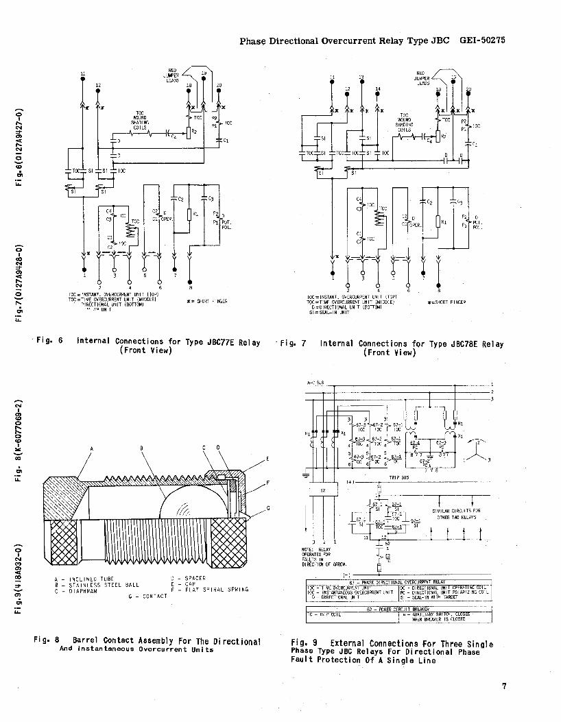
Internal Connections for Type JBC77E Relay (Front View)
o
A - I ~ClI NED TUBE o - SPACER B STAINLESS STEEL BALL C - OIAPHRAM
E CAP F - FLAT SPIRAL SPRING
G - CONTACT
Fig. 8 Barrel Contact Assembly For The Directional And Instantaneous Overcurrent Units
C4 c3 10C C3 TOC
P2 D Rl
Pi POT. POL.
C1
C2 IOC
frn rl·r 2 4 6 8
IOC = INSTANT. OV ERCURRENT UN I T (TOP) TOC=TIME OVERCURRENT UNIT (MIDDLE) *=SHORT FINGER
D=DIRECTIONAL UNIT (BOTTOM) SI=SEAL-IN UNIT
. fi g. 7 Internal Connections for Type JBC78E Relay ( F ron t View)
PrC I3lJS
NOTE: RELAY OPERATES FOR FAULTS IN 01 RECTI ON OF ARROW.
( )
J: 1 . J
SIMILAR CIRCUITS FOR OTHER TI'/J RELAYS
67 - PHASE DIRECT IONAL OVERCURRENT RELAY TOC TIME OVERCURRENT UNI OC - DIRECTIONAL UNIT OPERATING COIL IOC - INSTANTANEOUS OVERCURRENT UNIT PC - DIRECTIONAL UNIT POLARIZING COIL
D - DIRECTIONAL UNIT 51 - SEAL-IN WITH TARGET
TC - RIP COIL 52 - POWER CIRCUIT BREAKER 3.
a - AUXILIARY SWITCH, CLOSED WHEN BREAKER IS CLOSED
Fig. 9 External Connections For Three Single Phase Type JBC Relays for Directional Phase fault Protection Of A Single Line
7
GEI-50275 Phase Directional Overcurrent Relay Type JBC
stationary Contact Assembly
A - Contact Dial B - Contact Brush C - Contact Tip H - Contact Brush Retainer
K - Contact Support L - Mounting Screw M - Lockout
Moving Contact Assembly
D - Contact Arm E - Contact Brush
F - Contact Tip G - Contact Brush Retainer
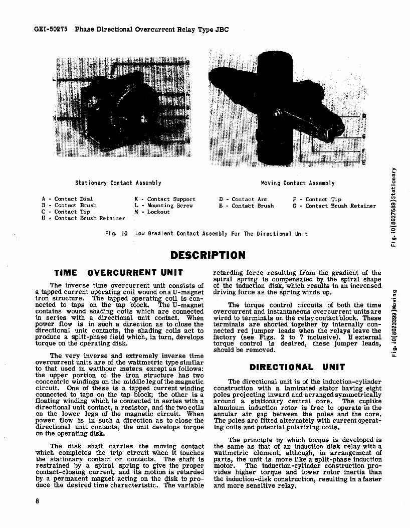
Fig. 10 Low Gradient Contact Assembly For The Directional Unit
DESCRIPTION
TIME OVERCURRENT UNIT The inverse time overcurrent unit consists of
a tapped current operating coil wound ona U-magnet iron structure. The tapped operating coil is connected to taps on the tap block. The U-magnet contains wound shading coils which are connected in series with a directional unit contact. When power flow is in such a dir.ection as to close the directional unit contacts, the shading coils act to produce a split-phase field which, in turn, develops torque on the operating disk.
The very inverse and extremely inverse time overcurrent units are of the wattmetric type similar to that used in watthour meters except as follows: the upper portion of the iron structure has two concentric windings on the middle leg of the magnetic circuit. One of these is a tapped current winding connected to taps on the tap block; the other is a floating winding which is connected in series with a directional unit contact, a resistor, and the two coils on the lower legs of the magnetic circuit. When power flow is in such a direction as to close the directional unit contacts, the unit develops torque on the operating disk.
The disk shaft carries the moving contact which completes the trip circuit when it touches the stationary contact or contacts. The shaft is restrained by a spiral spring to give the proper contact-closing current, and its motion is retarded by a permanent magnet acting on the 4isk to produce the desired time characteristic. The variable
8
retarding force resulting from the gradient of the spiral spring is compensated by the spiral shape of the induction disk, which results in an increased driving force as the spring winds up.
The torque control circuits of both the time over current and instantaneous overcurrent units are wired to terminals on the relay contact block. These terminals are shorted together by internally connected red jumper leads when the relays leave the factory (see Figs. 2 to 7 inclusive). If external torque control is desired, these jumper leads, should be removed.
DIRECTIONAL UNIT
The directional unit is of the induction-cylinder construction with a laminated stator having eight poles projecting inward and arranged symmetrically around a stationary central core. The cuplike aluminum induction rotor is free to operate in the annular air gap between the poles and the core. The poles are fitted alternately with currentoperating coils and potential polarizing coils.
The principle by which torque is developed is the same as that of an induction disk relay with a wattmetric element, although, in arrangement of parts, the unit is more like a split-phase induction motor. The induction-cylinder cons.truction provides higher torque and lower rotor inertia than the induction-disk construction, resulting in afaster and more sensitive relay.
~ ca c o +' ca +' en -en ao (Q ..... C'oI o ao -o
CI C
> :i! -g: C') C')
S ao -o

Phase Directional Overcurrent Relay Type JBC GEI-50275
INSTANTANEOUS OVERCURRENT UNIT
The instantaneous overcurrent unit is similar in construction to the directional unit described above, differing only in coil turns and connections. The four corner coils consist of two windings, an inner winding consisting of a large number of turns of fine wire, and an outer winding having a few turns of heavy wire. The outer windings of the corner coils, together with the four side coils, are all connected in series with the operating coil of the time overcurrent unit. The inner windings of the corner coils are all connected in series, and in turn are connected in series with a capacitor and a contact of the directional unit. This circuit thus controls the torque of the instantaneous overcurrent unit. When the directional unit contacts are open, the instantaneous overcurrent unit will develop no torque. When the directional unit contacts are closed, the instantaneous overcurrent unit will develop torque in proportion to the square of the current.
The instantaneous overcurrent unit develops operating torque in a direction opposite to that of the directional unit. This makes the relay less susceptible to the effects of shock.
SEAL·IN UNIT The seal-in units for both the time-overcurrent
and instantaneous-overcurrent contacts are mounted on the middle unit, as indicated in Fig. 1.
The left seal-in unit operates in conjunction with the time-overcurrent unit contacts and is labeled "T". Its coil is in series and its contacts in parallel with the main contacts of the timeovercurrent unit so that when the main contacts close, the seal-in unit will pick up and seal-in around the main contact.
The right seal-in unit, labeled "I" operates in conjunction with the instantaneous over current unit. tts coil is in series with the instantaneous unit contact and a contact of the directional unit, and its contacts are connected to seal-in around these two contacts when the unit operates.
Both seal-in units are equipped with targets which are raised into view when the unit operates.
These targets latch and remain exposed until manually released by means of the button projecting below the lower-left corner of the cover.
CONTACTS
LOW GRADIENT CONTACT
The directional unit contacts (left front), which control the time overcurrent unit are shown in Fig. 10. They are of the low gradient type specially constructed to minimize the effects of vibration. Both the stationary and moving contact brushes are made of low gradient material which, when subjected to vibration, tend to follow one another, hence, they resist contact separation.
The contact dial (A) supports the stationary contact brush (B) on which is mounted a conical contact tip (C). The moving contact arm (D) supports the moving contact brush (E) on which is mounted a button contact tip (F). The end of the moving contact brush bears against the inner face of the moving contact brush retainer (G). Similarly, the end of the stationary contact brush bears against the inner face of the stationary contact brush retainer (H). The stationary contact support (K) and the contact dial are assembled together by means of a mounting screw (L) and two locknuts (M).
BARREL CONTACT
The directional unit contacts (right rear), which control the instantaneous overcurrent unit, are shown in Fig. 8. They are specially constructed to suppress bouncing. The stationary contact (G) is mounted on a flat spiral spring (F) backed up by a thin diaphragm (C). These are both mounted in a slightly inclined tube (A). A stainless steel ball (B) is placed in the tube before the diaphragm is assembled. When the moving contact hits the stationary contact, the energy of the former is imparted to the latter and thence to the ball, which is free to' roll up the inclined tube. Thus, the moving contact comes to rest with substantially no rebound or vibration. To change the stationary contact mounting spring, remove the contact barrel and sleeve as a complete unit after loosening the screw at the front of the contact block. Unscrew the cap (E). The contact and its flat spiral mounting spring may then be removed.
INSTALLATION
LOCATION The location should be clean and dry, free from
dust and excessive vibration and well lighted to facilitate inspection and testing.
MOUNTING
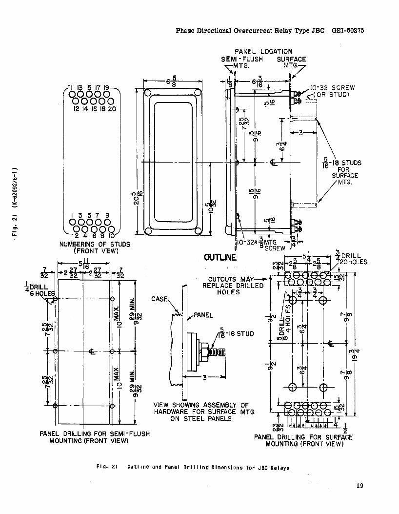
The relay should be mounted on a vertical surface. The outline and panel drilling diagram is shown in Fig. 21.
CONNECTIONS The internal connection diagrams for the various
relays are shown in Figs. 2 to 7. A typical wiring diagram is shown in Fig. 9. Since phase sequence is important for the correct operation of Type JBC relays, the rotation specified in Fig. 9 must be adhered to. Unless mounted on a steel panel which adequately grounds the relay case, it is recomIl1ended that the case be grounded through a mounting stud or screw with a conductor not less than #12 B&S gauge copper wire or its equivalent.
9

GEI-50275 Phase Directional Overcurrent Relay Type JBC
Terminal 12 of JBC51, JBC53, JBC77 relays should be connected to the negative side of the DC bus.
INSPECTION
At the time of installation, the relay should be inspected for tarnished contacts, loose screws, or other imperfections. If any trouble is found, it should be corrected in the manner described under MAINTENANCE.
NOTE: AFTER ENGAGING AUXILIARY BRUSH,CONNECTING'PLUG TRAVELS 1/4 INCH BEFOAE ENGAGING THE MAIN BRUSH ON THE TERMINAL BLOCK.
-01 CO) o 11'.
~ 00 -c:iI
*Fig. II Cross Section of Drawout Case Showing ~
CAUTION
Every circuit in the drawout case has an auxiliary brush. It is especially important on current circuits and other circuits with shorting bars that the auxiliary brush be bent high enough to engage the connecting plug or test plug before the main brushes do. This will prevent CT secondary circuits from being opened.
Position of Auxiliary Brush
OPERATION Before the relay is put into service, it should
be given a check to determine that factory adjustments have not been disturbed. The time dial will be set at zero before the relay leaves the factory. It is necessary to change this setting in order to open the time overcurrent unit contacts.
ADJUSTMENTS TIME OVERCURRENT UNIT
TARGET AND SEAL-IN UNIT (MARKED "T") When used with trip coils operating on cur
rents ranging from 0.2 to 2.0 amperes at the minimum control voltage, the target and seal-in tap screw should be set in the 0.2-ampere tap. When the trip-coil current ranges from 2 to 30 amperes at the minimum Control voltage, the tap screw should be placed in the 2.Q-ampere tap.
The seal-in tap screw is the screw holding the right-hand stationary contact of the seal-in unit. To change the tap setting, first remove the connecting plug. Then take a screw from the left-hand stationary contact and place it in the desired tap. Next, remove the screw from the other tap and place it back in the left-hand contact. This procedure is necessary to prevent the right-hand stationary contact from getting out of adjustment. Tap screws should never be left in both taps at the same time. CURRENT SETTING
The minimum current at which time overcurrent unit will close its contacts is determined by the position of the plug in the tap block. The tap plate on this block is marked in amperes, as shown in Table II.
When the tap setting is changed with the relay in its case the following procedure must be followed: (1) remove the connecting plug; this de-energizes the relay and shorts the current transformer secondary winding. (2) remove the tap screw and place it in the tap marked for the desired pick-up current. (3) replace the connecting plug.
The minimum current required to rotate the disk slowly and to close the contacts should be within five per cent of the value marked on the tap plate for any tap setting and time dial position. If this adjustment has been disturbed, it can be restored by means of the spring adjusting ring. The ring can be turned by inserting a screw driver blade in the
10
notches around the edge. By turning the ring, the operating current of the unit can be brought into agreement with the tap setting employed. This adjustment also permits any desired setting to be obtained intermediate between the availabe tap settings.
Test connections for making pickup and time checks on the time overcurrent unit are shown in Fig. 12. Use a source of 120 volts or greater with
120 VOLT A-C TEST SOURCE
POTEN T I OMETER 140 OHMS OR LESS)
o A-C TIMER
o 0 o
Fig. 12 Test Connections For Checking Pickup And Operating Time Of The Time Overcurrent Unit
-o I
CO) ..... 01 < 00
:::t-~
Phase Directional OVercurrent Relay Type JBC GEI-502715
good wave form and constant frequency. Stepdown transformers or phantom loads should not be employed in testing induction relays since their use may cause a distorted wave form.
TIME SETTING
The operating time of the time overcurrent unit for any given value of current and tap setting is determined by the time dial setting. This operating time is inversely proportional to the current magnitude as illustrated by the time curves in Figs. 18, 19 and 2'0. Note that the current values on these curves are given as multiples of the tap setting. That is, for a given time dial setting, the time will be the same for 80 amperes on the 8 ampere tap as for 50 amperes on the 5 ampere tap, since in both cases, the current is 10 times tap setting.
If selective action of two or more relays is required, determine the maximum possible shortcircuit current of the line and then choose a time value for each relayo that differs sufficiently to insure the proper sequence in the operation of the several circuit breakers. Allowance must be made for the time involved in opening each breaker after the relay contacts close. For this reason, unless the circuit time of operation is known with accuracy, there should be a difference of about 0.5 second (at the maximum current) between relays whose operation is to be selective.
INSERT TEST PLUG INTO RELAY Willi OONNECTIONS AS SHOWN BELOW.
TEST PLUG (aoTToM)
@ @ ( ~ @ 1 3 5 7 9 2 @j ~ 10
@ @
POWER FACTOR ANGLE 0- 45-I DEG. LEAD) 45 90
KW & KVAR DIRECTIONS KW OUT> WAR WITH RESPECT TO THE BUS 'HR II>
METER READ I NG WITH 90~ 135-PROPER EXT..CONNS. 135 180
STATIONi RELAY & ~AKER~ BUS .
KW OR KVAR
I I o IO±
± E
115V,
PHASE ANGLE METER
90- ng-135 lYAR,I .. , .,pl> IUR
180- 225-225 270
FLOW ''oUT''
:t
PHASE ANGLE METER READS ZERO DEG"REfS FOR ABOVE CONNECTIONS
180- 225- 270- m 225 270 315
Kr 'M> nAR lUI I. G~t ICXft~ OUT> I •• ·~r.~ ma 270 315~ 0 45 315 360 45 90
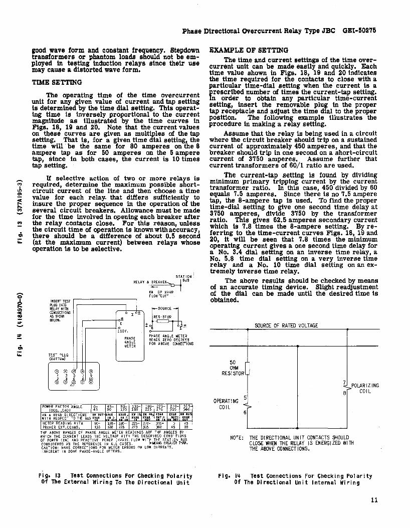
THE ABOVE RANGES OF PHASE ANGLE METER READINGS ARE THE ANGLES BY WH I CH THE CURRENT LEADS THE VOLTAGE WITH THE DESCR I BED CONO I T IONS OF POWER IKWI AND REACTIVE POWER IKVARI FLOW WITH THE STATION B~~ CONS I DERED AS THE REFERENCE I N ALL CASES. >MEANS GREATER TH • CAUT ION: MAKE CORRECT IONS fOR METER ERRORS ON LOW CURRENTS, I NHERENT I N SOME PHASE-ANGLE METERS.
Fig. 13 Test Connections For Checking Polarity Of The External Wiring To The Directional Unit
EXAMPLE OF SETTING The time and current settings of the time over
current unit can be made easily and quickly. Each time value shown in Figs. 18, 19 and 20 indicates the time required for the contacts to close with a particular time-dial setting when the current is a prescribed number of times the current-tap setting. In order to obtain any particular time-current setting, insert the removable plug in the proper tap receptacle and adjust the time dial to the proper position. The following example illustrates the procedure in making a relay setting.
Assume that the relay is being used in a cir.cuit where the circuit breaker should trip on a sustamed current of approximately 450 amperes, and that the breaker should trip in one second on a short-circuit current of 3750 amperes. Assume further that current transformers of 60/1 ratio are used.
The current-tap setting is found by dividing minimum primary tripping current by the current transformer ratio. In this case, 450 divided by 60 equals 7.5 amperes. Since there is no 7.5 ampere tap the 8-ampere tap is used. To find the proper tin:e-dial setting to give one second time delay at 3750 amperes, divide 3750 by the transformer ratio. This gives 62.5 amperes secondary current which is 7.8 times the 8-ampere setting. By referring to the time-current curves Figs. 18, 19 and 20, it will be seen that 7.8 times the minimum operating current gives a one second time delay for a No. 3.4 dial setting on an inverse time relay, a No. 5.8 time dial setting on a very inverse time relay and a No. 10 time dial setting on an extremely inverse time relay.
The above results should be checked by means of an accurate timing device. Slight readjustment of the dial can be made until the desired time is obtained.
SOURCE OF RATED VOLTAGE
50 J OHM RESISTOR
1 POLARIZING 8
OPERATING ~ CO I L ;:>
6
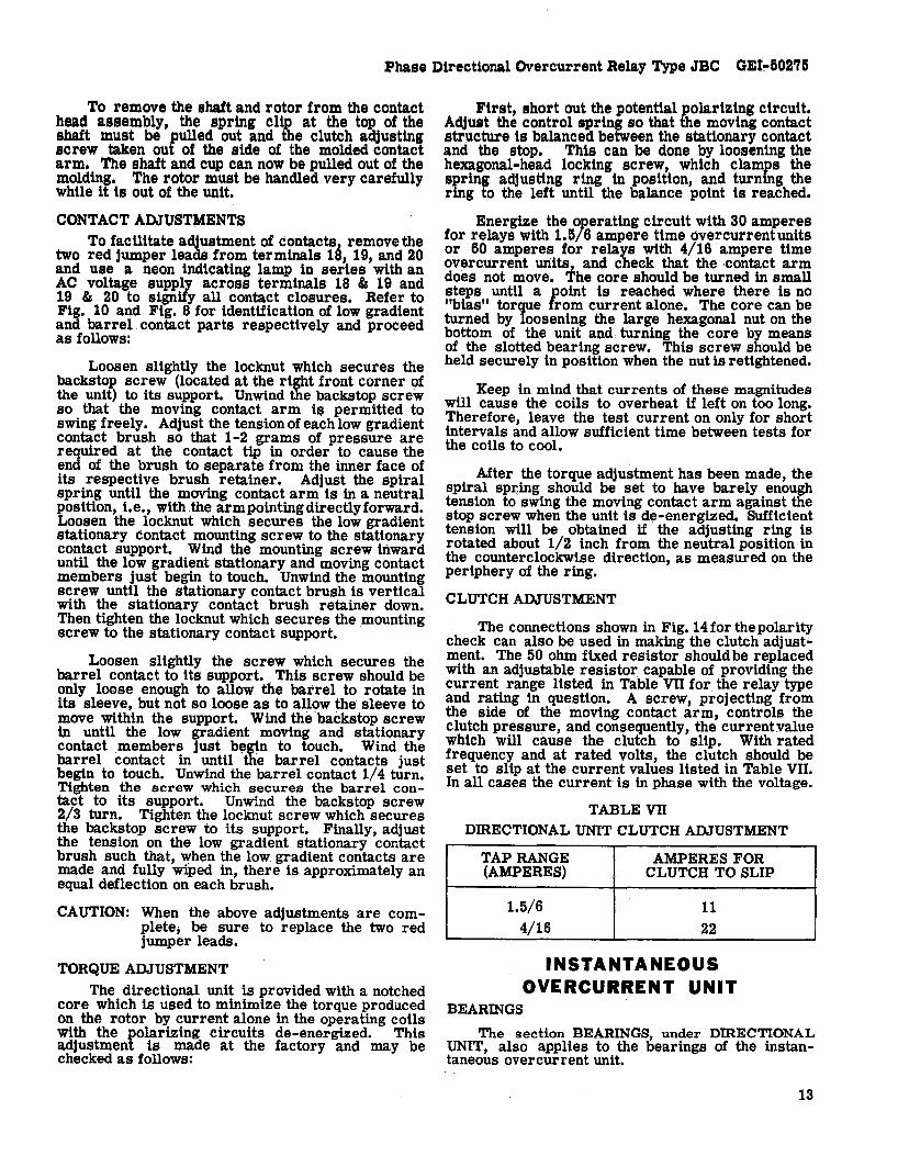
NOTE: THE DIRECTIONAL UNIT CONTACTS SiOULD CLOSE WHEN THE RELAY IS ENERGIZED WITH THE ABOVE CONNECTIONS.
COIL
Fig. I~ Test Connections For Checking Polarity Of The Directional Unit Internal Wiring
11

GEI-50275 Phase Directional Overcurrent Relay Type JBC
Aid in making the proper selection of relay settings may be obtained on application to the nearest Sales Office of the General Electric Company.
DIRECTIONAL UNIT POLARITY CHECK
The polarity of the external connections to the directional-unit may be verified by observing the direction of contact armature torque when the line is carrying load at unity power factor, or slightly lagging power factor. Note that in most directional overcurrent relay applications, the desired directions are: contact-closing for power flow away from the bus, and contact opening for power flow toward the bus. In case of doubt refer to Fig. 13 for a more accurate method of checking the polarity of the connections.
Fig. 14 shows the test connections for checking the polarity of the directional unit itself.
INSTANTANEOUS OVERCURRENT UNIT
TARGET AND SEAL-IN UNIT (MARKED "I") The target and seal-in unit for the instantaneous
overcurrent unit, is mounted on the right-hand side of the time overcurrent unit and is identified by a white "r' engraved on its front. The unit is identical with the target and seal-in unit of the time overcurrent unit, and the same instructions should be followed in adjusting the unit.
PICKUP SETTING
The pickup of the instantaneous overcurrent unit can be adjusted over a four-to-one range, as indicated in Table ill, by varying the tension of the spiral control spring. The outside end of this spring is fastened to a post on the adjusting ring above the moving contact, and the ring is in turn clamped in position by a hexagonal-head locking screw. If this screw is loosened, the ring can be sUpped to vary the spring tension.
In adjusting pickup, the desired pick-up current should be passed through the coils and the control spring should be adjusted until the contact just closes. The adjusting ring should then be locked in POSitiOR and the pick-up current rechecked. Note that the directional-unit contacts must be held closed during this adjustment.
MAINTENANCE These relays are adjusted at the factory and it
is advisable not to disturb the adjustments. If, for any reason, they have been disturbed, the following points should be observed in restoring them:
TIME OVERCURRENT UNIT DISK AND BEARINGS
The jewel should be turned up until the disk is centered in the air gaps, aft.er which it should be locked in this position by the set screw provided for this purpose. The upper bearing pin should next be adjusted so that the disk shaft has about 1/64 inch end play.
CONTACT ADJUSTMENT
The contacts should have about 1/32 inch wipe. That is, the stationary contact tip should be deflected about 1/32 inch when the disk completes its travel. Wipe is adjusted by turning the wipe adjustment screw thereby adjusting the position of the brush relative to the brush stop. On two-circuit closing relays, the two stationary contact tips should be in the same vertical plane.
When the time dial is moved to the position where it holds the contacts just closed, it should indicate zero on the time-dial scale. If it does not and the brushes are correctly adjusted, shift the dial by changing the position of the arm attached to the shaft just below the time dial. Loosen the screw clamping the. arm to the shaft and turn the arm relative to the shaft until the contacts just make for zero time-dial setting.
12
DIRECTIONAL UNIT BEARINGS
The lower jewel bearing should be screwed all the way in until its head engages the end of the threaded core support. The upper bearing should be adjusted to allow about 1/64 inch end play in the shaft.
To check the clearance between the iron core and the inside of the rotor cup, press down on the contact arm near the shaft thus depressing the spring-mounted jewel until the cup strikes the iron. The shaft should move about 1/16 inch.
CUP AND STATOR Should it be necessary to remove the cup-type
rotor from the directional unit, the following procedure should be followed:
All leads to the unit should first be disconnected and tagged for identification in reconnecting. The unit can then be removed from the cradle with its mounting plate still attached.
The upper of the three flat-head screws holding the unit to the plate should now be removed. On some models, it may be necessary to remove a resistor or capacitor to expose this screw. The four corner screws clamping the unit together, should next be removed, and the entire top structure lifted off. This gives access to the cup assembly and exposes the stator assembly, which should be protected to keep it free from dust and metallic particles until the unit is reassembled.
Phase Directional Overcurrent Relay Type JBC GEI~50275
To remove the shaft and rotor from the contact head assembly, the spring Clip at the top of the shaft must be pulled out and the clutch adjusting screw taken out of the side of the molded contact arm. The shaft and cup can now be pulled out of the molding. The rotor must be handled very carefully while it is out of the unit.
CONTACT ADJUSTMENTS To facilitate adjustment of contacts1 remove the
two red jumper leads from terminals 1~, 19, and 20 and use a neon indicating lamp in series with an AC voltage supply across terminals 18 & 19 and 19 & 20 to signify all contact closures. Refer to Fig. 10 and Fig. 8 for identification of low gradient and barrel contact parts respectively and proceed as follows:
Loosen slightly the locknut which secures the backstop screw (located at the right front corner of the unit) to its support. Unwind the backstop screw so that the moving contact arm is permitted to swing freely. Adjust the tension of each low gradient contact brush so that 1-2 grams of pressure are required at the contact tip in order to cause the end of the brush to separate from the inner face of its respective brush retainer. Adjust the spiral spring until the moving contact arm is in a neutral position, i.e., with the armpointingdtrectlyforward. Loosen the locknut which secures the low gradient stationary contact mounting screw to the stationary contact support. Wind the mounting screw inward until the low gradient stationary and moving contact members just begin to touch. Unwind the mounting screw until the stationary contact brush is vertical with the stationary contact brush retainer down Then tighten the locknut which secures the mounting screw to the stationary contact support.
Loosen slightly the screw which secures the barrel contact to its support. This screw should be only loose enough to allow the barrel to rotate in its sleeve, but not so loose as to allow the sleeve to move within the support. Wind the backstop screw in until the low gradient moving and stationary contact members just b~g~n to touch. Wind the barrel contact in until the barrel contacts just begin to touch. Unwind the barrel contact 1/4 turn. Tighten the screw which secures the barrel contact to its support. Unwind the backstop screw 2/3 turn. Tighten the locknut screw which secures the back~top screw to its s~pport. Finally, adjust the tenslOn on the low gradient stationary contact brush such that, when the low gradient contacts are made and fully wiped in, there is approximately an equal deflection on each brush.
CAUTION: When the above adjustments are complete; be sure to replace the two red jumper leads.
TORQUE ADJUSTMENT The directional unit is provided with a notched
core which is used to minimize the torque produced on the rotor by current alone in the operating coils with the polarizing circuits de-energized. This adjustment is made at the factory and may be checked as follows:
First, short out the potential polarizing circuit. Adjust the control spring so that the moving contact structure is balanced between the stationary contact and the stop. This can be done by loosening the hexagonal-head locking screw, which clamps the spring adjusting ring in position, and turning the ring to the left until the balance point is reached.
Energize the o~erating circuit with 30 amperes for relays with 1.5/6 ampere time Qvercurrentunits or 60 amperes for relays with 4/16 ampere time over current units, and check that the ,contact arm does not move. The core should be turned in small steps until a point is reached where there is no "bias" torque from current alone. The core can be turned by loosening the large hexagonal nut on the bottom of the unit and, turning the core by means of the slotted bearing screw. This screw should be held securely in position when the nut is retightened.
Keep in mind that currents of these magnitudes will cause the coils to overheat if left on too long. Therefore, leave the test current on only for short intervals and allow sufficient time between tests for the coils to cool.
After the torque adjustment has been made, the spiral spring should be set to have barely enough tension to swing the moving contact arm against the stop screw when the unit is de-energized. Sufficient tension will be obtained if the adjusting ring is rotated about 1/2 inch from the neutral position in the counterclockwise direction, as measured on the periphery of the ring.
CLUTCH ADJUSTMENT
The connections shown in Fig. 14 for the polarity check can also be used in making the clutch adjustment. The 50 ohm fixed resistor should be replaced with an adjustable resistor capable of providing the current range listed in Table vn for the relay type and rating in question. A screw, projecting from the side of the moving contact arm, controls the clutch pressure, and consequently, the current value which will cause the clutch to slip. With rated frequency and at rated volts, the clutch should be set to slip at the current values listed in Table VII. In all cases the curreni- is in phase with the voltage.
TABLE VII DffiECTIONAL UNIT CLUTCH ADJUSTMENT
TAP RANGE AMPERES FOR (AMPERES) CLUTCH TO SLIP
1.5/6 11 4/16 22
INSTANTANEOUS OVERCURRENT UNIT
BEARINGS
The section BEARINGS, under DIRECTIONAL UNIT, also applies to the bearings of the instantaneous overcurrent unit.
13

GEI-50275 Phase Directional Overcurrent Relay Type JBC
CUP AND STATOR The section CUP AND STATOR under DffiEC
TIONAL UNIT, also applies to the cup and stator of the instantaneous overcurrent unit.
CONTACT ADJUSTMENTS The contact gap may be adjusted by loosening
slightly the screw at the front of the contact support. The screw should be only loose enough to allow the contact barrel to rotate in its sleeve.
The backstop screw fastened with a locknut should hold the moving contact arm in a neutral position, i.e., with the arm pointing directly forward. Then, by rotating the barrel, advance the stationary contact until it just touches the moving contact. Next, back it away 2/3 turn to obtain approximately 0.020 inch gap. Last, tighten the screw which secures the barrel.
The moving contact may be removed by loosening the screw which secures it to the contact arm and sliding it from under the screw head.
TABLE VIII INSTANTANEOUS OVERCURRENT UNIT
CLUTCH ADJUSTMENT PICKUP CLUTCH MUST CLUTCH MUST RANGE NOT SLIP AT SLIP AT
2 - 8 12 16 4 - 16 24 32
*10 - 40 - -, *20 - 80 - -
*40 - 160 - -* Tighten clutch as much as possible.
CLUTCH ADJUSTMENT
The clutch on the instantaneous overcurrent unit can be adjusted by means of the screw located on the right-hand side of the moving contact arm. If the locknut is loosened and the screw turned in, the current at which the clutch will slip will be increased. ·The clutch shuuld be adjusted to slip at the current values shown in Table YIn with the directional unit contacts held closed.
CONTACT CLEANING
For cleaning fine silver contacts, a flexible burnishing tool should be used. This consists of a flexible strip of metal with an etched roughened surface, resembling in effect a superfine file. The polishing action is so delicate that no scratches are left, yet corroded material will be removed rapidly and thoroughly. The flexibility of the tool insures the cleaning of the actual points of contact.
Fine silver contacts should not be cleaned with knives, files or abrasive paper or cloth. Knives or files may leave scratches which increase arcing and deterioration of the contacts. Abrasive paper or cloth may leave minute particles of insulating abrasive material in the contacts thus preventing contact closing.
The burnishing tool described above can be obtained from the factory.
RENEWAL PARTS It is recommended that sufficient quantities of
renewal parts be carried in stock to enable the prompt replacement of any that are worn, broken, or damaged.
nearest Sales Office of the General Electr.ic Company, specify quantity required, name of part wanted, and give complete nameplate data. If pOSSible, give the General Electric Company requisition number on
14
When ordering renewal parts, address the * which the relay was furnished. Refer to Renewal
Parts Publication GEF-4086. ~
Q , .... ~ 50 ... u ,. ... <I)
::> a 110
<1)-
e» z .... 00: U"" ~o-::;;;; 30 ... ::> - ... ::t ..
~~ ....... 20 zu - .... 0-0: (,!Jzoe>
11>0 10 0<1)
"'0-Uu ..
0-z:
'" 0 u 0
<
\ cu RV E HI N I ~~~4 _ ~ I ~k~r CURVE B-T"U TH'lES MIN. F.U. CUfiVE C-TlIREE TlflES r·IIN. ~.U • CURV ED-hAll I MU~I ~ I CI\UP
\
B 1\
~ \ "\ ~~ r---
~ ~ -
2 11 e 8 10 MUl T I PlES OF PICKUP CURRENT
OF INSTANTANEOUS OVERCURRENT UNIT
Fig. 15 Instantaneous Overcurrent Unit Time Curve
-c-.I I
0) (\') :::t <0 In In <0 I
:..:: -

Phase Directional Overcurrent Relay Type JBC GEI-50275
.060 I
!!!.l!!§.
.0,0
.O~O
In
" • 0 g
.030 In
• -~ I- .020
-C'I I
.010 ::t-eo ~
"'.'.'} -
\ h-4 AMPS
1. ,·6. 0 2·8 -
\ 120 VOLTS
60 CYCLES
\ ~ r--- L ,.0 VOLTS
"--- I
/2~ VOLT,S
~ 1'_
It)
CO '110 VOLTS I
iIII: -!:::
~o 20 60 30 '+0 70
AUlaES g. ...
Fi g. 16 Directional Unit Time Curve (1.5/6 Ampere Range) for Voltage Applied in Phase with Current
- .06 C'I
, I
CO) eo ~
, RATING ---
It) .O!) '+-16 AMPS -
CO - 120 VOLTS
!2 60 CYCLE S
g. .O~
In ... 0 z 0 u ... In .03
! !oJ • I- .02
.01
\ \ 'i'---- /,.0 VOLTS
~ •
/25 VOLTS -- .... 110 VOLTS
10 20 '+0 50 60 70 80
AMPERES
Fig. 17 Directional Unit Time Curve (~/16 Ampere Range) for Voltage Appl ied In Phase with Current
15

GEI-50275 Phase Directional Overcurrent Relay Type JBC
16
CI') Q Z 0 <.) LU CI')
z
LU ::E
t-
50
40
30
20
10 9 8 7
8
5
4
3
2
1 .8 .8 .7
.8
.5
.4
.3
.2
.1 .09 .08 .07 ,06
.05
.C4
.03
.02
.01 .5 .8 .7 .8 .9 1
T
~ \
\. \1'.. \\. "" \\. '" l".. \\ l\,.' -"' r---\. "'- "'- , \ \. 'I.,. '" l"- t-.. \ I"- ,,-=" \. "- " '" 1''' ..... t-..
\ ~ I" " '" I' 1'-" '"
r-. r--, r---... 1\ \ ~
, "
I" ""' I"'- r--, r--~ t'--... "- .....
\ "- f', "t'--J". ~ ~ -.. r--.
t'-... " t-.... i'- r--, r---... j'-.... r-- r-- 10
~ I"- I'r---.. : ...... r--, r:::: ~ r--. r---~~ 9 " l"- I---r-- r--. r-- r--.
~ !'" ..... r-- r-- r-- 8 " r-. t---. r--- 7 \. 1"- ...... r-.. r--. l-\. .....
""" ::::-- -- I~ " r-- ..... ~ en
"- '" ~ -- I"- IV' 0» c: l-
I' I ......... t--r-- r-- 4 .--"'- --... " -r ... " ; 3 Q)
" f'., , r- b.", en ., ...... 1'"
"
2 -l"-r--, 1--- 0 t---. .-r--. I" l-I- t- O r-
r--- I Q)
t-- t-- E i-r-~
.-t-
2 3 4 5 6 7 8 910 20 30 40 50 60 7080 9O!
MULTIPLES OF RELAY TAP SETTING
. Fig. 18 Typical Time Curves for Inverse Time Overcurrent Unit (JBC51 and JBC52)
-o I
Q) 10 N o al 00 00 00 o -00

CI') Q Z
8 ~ z
LI.I ::z I-
00
40
30
20
10 8 8 7
8
5
3
2
1 e 8 7
8
5
4
3
2
.1 8 8
.0
.0
.0
.0
.0
7
a 5
.0 4
.0 3
.0 2
1 .0.5 .8 .7 .a .8 1
Phase Directional Overcurrent Relay Type JBC GEI-50275
" r~
\\ \\\ \\\\ ~\\" ~~
\ 1\\ ,\U\
\ \ 1\, l\\ \ \ ~\' l\\ \ .\' !\\ 1\\
\ \ .\ \ \ \ .\ \ \ 1\ 1\ ,'1\ \ \ \ 1\ .. \1\
1\ \ \ 1\ .\ [\ I\[\.
1\ I\~ " ~ ~ \ \ \ ,
\1' :\ "- r--- .... 1' 1\ , \ \ [\/' ~ "- "- I'::::::::: ~ 1\ 1\ l"- i"- .... t-1\ i\ ~ r-.~ ~ t- ..... 1O
" ..... \ \ -" ....... ~ 9 1-1-\ ,.....,
" r-\ " r-. ..... -" ..... 8 f-I-
\ 1\ r-. ............ r- r-7 en 1\ [\
'" f'..... --.. r- 6 c:J' \ \ "- f"'-.,. 5 c .-...... -- +-
\ I' ......... 4 +-CD
\ \ .... ---- CJ)
1\ 1'\ ............ 3 -"~ r--t- o
I\- '- .-1\ ""'r-. 2 0
1'\ "'r--... CD
" ..... r---- E r-...
t"--" t- r- t- .-l- I t-.......
t-....... 1 2
2 3 4 5 8 7 8 910 20 30 40 50 80 70 aD 90!=
MULTIPLES OF RELAY TAP SETTING
Fig. 19 Typical Time Curves for Very Inverse Time Overcurrent Unit (JBC53 and JBC5lj.)
17

GEI-50275 Phase Directional Overcurrent Relay Type JBC
18
en Q
.0
40
30
20
10 8 8 7
8
5
4
3
2
~ 1 C,) .8 LIJ .8 en .7
z: .8
LIJ .,
::z: - .4
.3
.2
.1 [.08 'Jl8 .07
.08
.05
.0 3
.0 2
q 1
:
, .5 .8,.7.8.8 1
l\ k\\ ~ ~~
~ ~ \T >IT
,\ \\'
'" [\ \\ \\ \ \\ \\ \
\ \ \ \ 1\ \ \ \
1\ \
\ 1\ \ \
f\ 1\ \ ,
2
,\ \\' ~\' [\
\
1\ ,\ \ \\\\
,\ .'\~\ 1\ ,\ ~" r\- l\ [\\ ~l\ '1\ 1\ ~~~ ~ '.
1\ r" 1\ I\~ ~ ~ \ , \. \. ,\. .\.
,\. .\ \ 1\ \ \' [\ .\
\\ I" 1\ 1\ '\ \ \1\ [\1\
\. \. \. .\.y , 1\ IX XX 1\ X X'\. '\.
1\ ~ \.\" \. \ i\ 1\ \
1\ '" ~
r\ 1\ 1\ 1\ r-.,.\. "'\ ~ ~ I'-.. I- 10 [\ \.
f\ ~~ ~ ...... r--.. l-t-
~ 1\ t-..... l-t-f' 1\.'\ ~
....... t-
f\ 1\ t'-... I'-.. l-t- 7 I'-.. 5 (I)
t-~ ,
"" 5 0- r-e '\ 1\ I-.. 4 -'\. '" --..:.. -'\. " I- -1-3 CD
~ "" """ r- t- en "' " 2 -, ""'- 0
""'\: "'" .-0
~ ...... t..... I I': CD H-
I- r-.l E .-2 I-
3 4 5 8 7 8 810 20 30 40 50 80 70808052
MULTIPLES OF RELAY TAP SETTING
'Fig, 20 Typical Time Curves for Extremely Inverse Time Overcurrent Unit (JBC77 and JBC7S)
.....
--C'I
I r -
, I~ 0 N
li)
x <[ ~ ~ :IE o Oll'"
I - N~ en
PANEL DRILLING FOR SEMI-FLUSH MOUNTING (FRONT VIEW)
Phase Directional Overcurrent Relay Type JBC GEI-50275
6 8 ~1
--
~
Jl
: /118
~ 3~
PANE:L LOGATION SURFACE
MTG7
_~~~JO ~~~~==t: ~ 10-32 SCREW 11= :e( OR STUD)
: .... J
I r ~-.. :>~ ""10;1" w
fe-IS STUDS FOR
SURFACE /MTG .. .:..:.. .. ::.3
VIEW SHOWING ASSEMBLY OF HARDWARE FOR SURFACE MTG.
ON STEEL PANELS
Fig. 21 Outline and Panel Drilling Dimensions for JBC Relays
19

GENERAL ELECTRIC COMPANY POWER SYSTEMS MANAGEMENT BUSINESS DEPT.
PHILADELPHIA, PA. 19142
GENERAL" ELECTRIC
3-77 2-60