design and implementation of overcurrent protection relays
TRANSCRIPT

Graduate Theses, Dissertations, and Problem Reports
2019
Design and Implementation of Overcurrent Protection Relays Test Design and Implementation of Overcurrent Protection Relays Test
Bench Bench
Khalid Daud Khattak [email protected]
Follow this and additional works at: https://researchrepository.wvu.edu/etd
Part of the Electrical and Electronics Commons, and the Power and Energy Commons
Recommended Citation Recommended Citation Khattak, Khalid Daud, "Design and Implementation of Overcurrent Protection Relays Test Bench" (2019). Graduate Theses, Dissertations, and Problem Reports. 7468. https://researchrepository.wvu.edu/etd/7468
This Thesis is protected by copyright and/or related rights. It has been brought to you by the The Research Repository @ WVU with permission from the rights-holder(s). You are free to use this Thesis in any way that is permitted by the copyright and related rights legislation that applies to your use. For other uses you must obtain permission from the rights-holder(s) directly, unless additional rights are indicated by a Creative Commons license in the record and/ or on the work itself. This Thesis has been accepted for inclusion in WVU Graduate Theses, Dissertations, and Problem Reports collection by an authorized administrator of The Research Repository @ WVU. For more information, please contact [email protected].

Design and Implementation of Overcurrent Protection
Relays Test Bench
Khalid Daud Khattak
Thesis submitted to the
College of Engineering and Mineral Resources
at West Virginia University
in partial fulfillment of the requirements
for the degree of
Master of Science
in
Electrical Engineering
Muhammad A. Choudhry, Ph.D., Chair
Ali Feliachi, Ph.D.,
David W. Graham, Ph.D.
Lane Department of Computer Science and Electrical Engineering
Morgantown, West Virginia
2019
Keywords:
Overcurrent Protection Relay Test Bench, SEL-751A Feeder Protection Relay, Serial
Communication, COM Ports, ACSELERATOR QuickSet®, Electromechanical CO-8 (Inverse
Time) Relay, Power Simulator
Copyright 2019 Khalid Daud Khattak

ABSTRACT
Design and Implementation of Overcurrent Protection Relays
Test Bench
Khalid Daud Khattak
The electrical power simulator in Engineering Sciences Building (ESB) at WVU was dismantled
in July 2018. The simulator was used as a teaching tool for EE students to conduct lab experiments.
The power simulator employed electromechanical and microprocessor protection relays, manual
isolation and industrial circuit breakers, switches, variable autotransformer (VARIAC), voltmeters
and ammeters. During the dismantling, a lot of equipment was retrieved for future possible use.
This led to the idea of designing and implementing a simple circuit on a test bench that can be used
as a lab equipment to demonstrate the operation of overcurrent protection relays. It was decided to
design the circuit so that it employs equipment removed from the power simulator including
microprocessor-based SEL-751A Feeder Protection Relays, Westinghouse CO-8
electromechanical relays, variable autotransformer (VARIAC), voltmeter, ammeter, isolation
circuit breaker, and a tripping circuit breaker. A circuit test bench, available in the lab, was
modified for this purpose. The bench provides the advantage of having a setup on a small and
movable platform.
The circuit of the Overcurrent Protection Relays Test Bench has a variable autotransformer
with protection relays, protection breakers and changeover switches installed on the primary and
secondary side of the transformer. SEL-751A or three electromechanical CO-8 relays, one on each
phase, can be selected as the main protection device on both sides of the transformer. There was
only one industrial circuit breaker available in the lab. This has been installed on the secondary
side. For the primary side, a breaker circuit has been designed and used which uses general-purpose
DPDT and electronic relays, DC power supply, voltage limiting resistors, toggle switch and push-

button reset switch. This use of the breaker circuit has saved a lot of costs since most of the
components used in the design were already available in the lab.
Based on the cost-effective design, it is planned to design a similar circuit that can demonstrate
the operation of differential current protection relay based on SEL-387A Current Differential
Relay.

iv
Acknowledgements
I am grateful to my advisor Dr. M.A Choudhry, without whose guidance and support this
project would have been impossible to complete. In fact, this project was his brainchild. Despite
his knowledge and experience in the field of Electrical Power Systems and Protection of Power
Systems, I have always found him to be humble and ready to help his students. Sir, you truly have
been an inspiration!
I am thankful to Dr. Ali Feliachi, with whom I have taken a lot of graduate level courses.
He has helped me a lot in understanding the core concepts of Linear Control Systems, Analysis of
Power Systems and Optimal Control. Despite my shortcomings, Dr. Feliachi has always been
understanding and patient with me.
I am also grateful to Dr. David W. Graham for agreeing to be a part of my defense
committee. I have learnt a lot from him in EE 551 Linear Integrated Circuits.
I wish to thank all the new friends I have made during my stay here at WVU for their
support and the good times we shared.
I also want to extend my deepest gratitude to my parents for their unconditional love and
support.
Finally, I am grateful to my uncle Fazal H. Khattak who has always been there for me and
made my life considerably easy in a new place.

v
Contents List of Figures ............................................................................................................................................ vii
List of Tables .............................................................................................................................................. ix
Introduction ................................................................................................................................................. 1
1.1 Background and Motivation ............................................................................................................ 1
1.2 Scope of Document ............................................................................................................................ 2
1.3 Design Challenges ............................................................................................................................. 2
System Design and Working ...................................................................................................................... 5
2.1. Procedure for Using the Overcurrent Protection Relays Test Bench .................................... 8
2.2. System Limitations ...................................................................................................................... 9
Hardware Details ...................................................................................................................................... 10
3.1 10A Isolation Breaker (A) .............................................................................................................. 10
3.2 Transformer Primary Side Protection Breaker Circuit (B)........................................................ 11
3.3 SEL-751A Feeder Protection Relay (C1 and C2) ......................................................................... 13
3.3.1. SEL-751A Wiring Details ....................................................................................................... 14
3.4 Westinghouse CO-8 (Inverse Time) Electromechanical Overcurrent Relay (D1, D2, D3, D4, D5 and D6) ............................................................................................................................................. 15
3.5 General Electric (GE) AC Voltmeter (E) ...................................................................................... 18
3.6. General Electric (GE) AC Ammeter (F) ...................................................................................... 18
3.7. Primary Side and Secondary Side Changeover Switches (G1 and G2) .................................... 19
3.8. Variable Autotransformer - VARIAC (H) .................................................................................. 19
3.9. GE Industrial Circuit Breaker for Transformer Secondary Protection (I) ............................. 20
3.10. Load Connection Ports (J) .......................................................................................................... 21
3.11. Full Wave Bridge Rectifier Circuit ............................................................................................ 22
SEL Feeder Protection Relay Communication and Monitoring Setup ................................................ 24
4.1. Hardware Connections .................................................................................................................. 27
4.2. Establishing Ethernet Connection between PC and SEL-3351 Computing Platform ............. 27
4.3. SubstationSERVER.NET Setup ................................................................................................... 32
4.4. ACSELERATOR QuickSet® Settings .............................................................................................. 45
4.4.1. ACSELERATOR QuickSet Communication Settings (Direct Communication) .................. 45
4.4.2. ACSELERATOR QuickSet® Communication Settings (Through Database) ........................ 50
vi
4.5. SEL 751-A Feeder Protection Relay Settings .............................................................................. 56
4.5.1. Accessing and Modifying SEL Relays Settings with QuickSet ........................................... 56
4.5.2. Accessing and Modifying SEL Relays Through Terminal .................................................. 60
4.6. Monitoring ...................................................................................................................................... 64
FUTURE WORK ...................................................................................................................................... 73
Appendix .................................................................................................................................................... 76
Appendix A- Overcurrent Protection Relays Test Bench Circuit Schematics ................................ 76
Appendix B- SEL -751A Settings Definitions ..................................................................................... 76
Appendix C- US Inverse Time Relay Operating Time vs. Multiples of Pick-up Current .............. 76
Appendix D- List of Passwords ............................................................................................................ 76
Appendix E- Parts List ......................................................................................................................... 76
References .................................................................................................................................................. 94

vii
List of Figures
Figure 1.1 Front view of power simulator that was dismantled, Spencer [1] .............................................. 1 Figure 1.2 Connection bench that was modified for the overcurrent relay setup ........................................ 3 Figure 2.1 Front view of the Overcurrent Protection Relay Test Bench ...................................................... 5 Figure 2.2 Front layout of the Overcurrent Protection Relay Test Bench ................................................... 6 Figure 3.1 Main isolation breaker .............................................................................................................. 10 Figure 3.3 Front and rear view of the breaker circuit used for primary side protection ........................... 12 Figure 3.4 SEL-751A Feeder Protection Relay front view ......................................................................... 14 Figure 3.5 Rear view of SEL-751A ............................................................................................................. 15 Figure 3.6 CO-8 Electromechanical overcurrent protection relay ............................................................ 16 Figure 3.7 Rear view of CO-8 electromechanical overcurrent relay ......................................................... 17 Figure 3.8 AC voltmeter installed in the test bench .................................................................................... 18 Figure 3.9 AC ammeter installed in the test bench ..................................................................................... 18 Figure 3.10 Cam changeover switch front and rear view .......................................................................... 19 Figure 3.11 Variable autotransformer front view and rear view. Voltage can be adjusted with the knob 20 Figure 3.12 GE Industrial circuit breaker used in the test bench .............................................................. 21 Figure 3.13 Load connection ports. ............................................................................................................ 22 Figure 3.14 Schematic of bridge rectifier circuit for the industrial circuit breaker ................................... 22 Figure 3.15 Full wave rectifier circuit used in the test bench .................................................................... 23 Figure 4.1. Communication set up for SEL microprocessor-based relays. ............................................... 25 Figure 4.2. Procedure employed for configuring and monitoring SEL relays ........................................... 26 Figure 4.3 Accessing Network Places ......................................................................................................... 28 Figure 4.4 Network Connections ................................................................................................................ 29 Figure 4.5 Network Properties ................................................................................................................... 30 Figure 4.6 Accessing IP properties ............................................................................................................. 31 Figure 4.7 SubstationSERVER.NET ........................................................................................................... 32 Figure 4.8 Computing Platform Desktop with SSNET Explorer icon ........................................................ 34 Figure 4.9 Main screen when SSNET Explorer is launched. Status of various is indicated as shown. ...... 35 Figure 4.10 Stopping all services. .............................................................................................................. 35 Figure 4.11 Defining new COM port under SEL Fast Messaging ............................................................. 36 Figure 4.12 Renaming serial COM port ..................................................................................................... 37 Figure 4.13 COM port configuration ......................................................................................................... 38 Figure 4.14 Starting the Online Relay Wizard ........................................................................................... 39 Figure 4.15 Successful completion of auto configuration .......................................................................... 39 Figure 4.16 Defining serial COM port under Terminal Server .................................................................. 40 Figure 4.17 Changing the name of newly defined COM port ..................................................................... 41 Figure 4.18 Selecting COM port from Shared drop-down menu. ............................................................... 43 Figure 4.19 Setting network properties ...................................................................................................... 43

viii
Figure 4.20 Start Port Server services........................................................................................................ 44 Figure 4.21 Another way of starting services. ............................................................................................ 44 Figure 4.22 Services running. ..................................................................................................................... 45 Figure 4.23 Launching QuickSet ................................................................................................................ 46 Figure 4.24 Accessing communication parameters from the main menu. .................................................. 47 Figure 4.25 Setting communication parameters in QuickSet ..................................................................... 48 Figure 4.26 Confirming successful communication in QuickSet ................................................................ 49 Figure 4.27 Access to ACSELERATOR Database ......................................................................................... 50 Figure 4.28 Adding a new device in the database ...................................................................................... 51 Figure 4.29 Selecting Device Type ............................................................................................................. 51 Figure 4.30 Accessing device properties .................................................................................................... 52 Figure 4.31 Entering communication parameters. ..................................................................................... 53 Figure 4.32 Connecting a relay with QuickSet ........................................................................................... 54 Figure 4.33 Connected device .................................................................................................................... 55 Figure 4.34 Reading data from a connected device ................................................................................... 56 Figure 4.35 Reading device data of a relay configured in database. ......................................................... 57 Figure 4.36 Device data being read from relay .......................................................................................... 57 Figure 4.37 Detailed device settings. Settings can be read, modified and sent to device........................... 58 Figure 4.38 Selecting settings to send to the device ................................................................................... 59 Figure 4.39 Relay data can be saved in PC and loaded and sent to relay latter on. .................................. 59 Figure 4.40 Launching Terminal from ACSELERATOR QuickSet ................................................................ 60 Figure 4.41 Terminal window ..................................................................................................................... 60 Figure 4.42 Level 1 of SEL-751A. SHO is entered to show relay settings.................................................. 61 Figure 4.43 Accessing the HMI in QuickSet ............................................................................................... 65 Figure 4.44 Device Overview on HMI ........................................................................................................ 66 Figure 4.45 Viewing phasor representation of live current and voltage values. ........................................ 67 Figure 4.46 Fundamental metering values ................................................................................................. 68 Figure 4.47 Getting Events Files ................................................................................................................ 69 Figure 4.48 List of events. ........................................................................................................................... 69 Figure 4.49 Saving Events .......................................................................................................................... 70 Figure 4.50 Opening AcSELerator Analytic Assistant in the lab PC ......................................................... 71 Figure 4.51 Opening event file in in AcSELerator Analytic Assistant ........................................................ 71 Figure 4.52 Graphs of currents and voltages from the event file. Phasor representation can also be obtained from the options. .......................................................................................................................... 72 Figure 5.1 Differential current protection circuit test setup ....................................................................... 74 Figure 5.2 Device Overview of SEL-387A during normal operation. ........................................................ 74 Figure 5.3 Phasor representation of differential currents. ......................................................................... 75 Figure 5.3 Device Overview of SEL-387A when relay trips. ...................................................................... 75

ix
List of Tables Table 3.1 Details of SEL-751A wiring ........................................................................................................ 14 Table 3.2 Details of CO-8 overcurrent relay .............................................................................................. 17 Table 4.1 IP properties used for PC with QuickSet and SEL-3351 Computing Platform .......................... 31 Table 4.2 Protocols supported by SubstationSERVER.NET installed on the Computing Platform ........... 33 Table 4.3 Serial Properties for SEL-751A .................................................................................................. 38 Table 4.4 Configuration of COM properties .............................................................................................. 42 Table 4.5 SEL-751A levels details .............................................................................................................. 61 Table 4.6 SEL-751A Settings categories pertinent to this project. ............................................................. 62

CHAPTER 1. INTRODUCTION
1
Chapter 1
Introduction
This thesis report describes the details of design and implementation of Overcurrent Protection
Relays Test Bench. The test bench is designed as a lab apparatus, especially for students and
researchers working in the field Protection of Power Systems. The test bench employs
microprocessor-based SEL-751A Feeder Protection Relays and electromechanical type
Westinghouse CO-8 inverse time overcurrent relays.
1.1 Background and Motivation The Lane Department of Computer Science Electrical Engineering (LCSEE) at West Virginia
University (WVU) had a power simulator installed in the 1970s, Spencer [1]. The original design
of the simulator employed analog relays. The simulator was later upgraded with microprocessor-
based relays donated by Schweitzer Engineering Laboratories (SEL), Spencer [1].
The department decided to establish an Innovation Lab in the room that housed the power
simulator. As a result, the simulator was dismantled in July 2018 and the power system equipment
was moved to a new Energy Systems Lab in the Engineering Research Building (ERB) room 219.
Considering the cost and applications of industrial circuit breakers, VARIAC, switches,
resistors, meters, potential transformers, and electromechanical and microprocessor electrical
Figure 1.1 Front view of power simulator that was dismantled, Spencer [1]

CHAPTER 1. INTRODUCTION
2
protection relays which were removed from the simulator, it was decided to salvage this equipment
for possible future use. The intention to put most of the equipment removed from the simulator
into academic use, motivated the idea of designing and building a small test bench that could easily
be moved and demonstrate the working of electrical overcurrent protection relays which are one
of the key elements in electrical protection systems. The availability of two main types of
overcurrent relays i.e., electromechanical type CO-8 inverse time overcurrent relays and the more
versatile modern microprocessor feeder protection relays; which apart from providing
instantaneous and time overcurrent protection over various US and IEC curves also provide
various other protection features, mainly over and under voltage protection, frequency variation
protection and power factor lead/lag protection; provided an opportunity to design a test bench that
can be used to show the application, working, configuration process and advantages/benefits of
both types of relays.
1.2 Scope of Document
Section 2 describes the operation of the Overcurrent Protection Relays Test Bench and can be
used as a guide for anyone using the bench. Section 3 provides brief overview of equipment used
in the design and implementation of the overcurrent protection relays test bench. Section 4 outlines
the step-by-step procedure used for configuring the SEL-751A Feeder Protection Relays to
communicate with PC running SEL ACSELERATOR QuickSet® SEL-5030 software through SEL-
3351 Computing Platform with Substation SERVER.NET. ACSELERATOR QuickSet® SEL-5030
software can be used to access and modify the relay settings and display relay data, SEL [2] and
SEL [3]. Circuit schematics, description of SEL-751A settings, US curves for Inverse Time relays,
login passwords and parts list are presented as Appendices.
1.3 Design Challenges
In an effort to keep the cost at minimum, the design attempts at the maximum use of equipment
already available in the Energy Systems Lab. The lab has four benches that were used with motor-
generator sets for lab experiments. The motor generator set is not used anymore and these benches
are used by students for their senior design project for providing electrical connections. Since these
benches can be easily moved and four were available, it was decided to modify one of these
benches for this project. The dimensions of the panel (approximate dimensions: length = 41.5 in.,
width = 6 in. and height = 25.5 in.) presented a challenge as the design of three phase circuit

CHAPTER 1. INTRODUCTION
3
required that six electromechanical overcurrent relays, two microprocessor feeder protection
relays, three breakers and a variable autotransformer fit into the panel. The layout of the
Overcurrent Protection Relay Test Bench was greatly influenced by placement of the transformer
as it is quite heavy and its depth is almost three times the depth of the connection bench that was
selected for this application. The autotransformer had to be placed low otherwise the bench would
have become unstable due to the weight and dimensions of the transformer.
Very less information was available about the power simulator that was removed. By design,
SEL relays, installed in the power simulator, were connected with SEL-3351 Computing Platform,
which can support multiple devices. However, no description of the communication setup between
the relays and the Computing Platform and between the Computing Platform and lab PC was
available. This presented an issue and required considerable time to address.
The circuit design of the Overcurrent Protection Relays Test Bench requires the use of two
circuit breakers that can be operated by overcurrent protection relays. One circuit breaker is
required at the transformers primary side and the other circuit breaker is required at the transformer
secondary side. Only one industrial circuit breaker was available in the lab. This has been used at
the secondary side of the transformer. Ordering a new circuit breaker for the primary side was not
Figure 1.2 Connection bench that was modified for the overcurrent relay setup

CHAPTER 1. INTRODUCTION
4
an option as that would have raised the cost considerably. Instead, a breaker circuit for primary
side protection had to be designed.

CHAPTER 2. SYSTEM DESIGN AND WORKING
5
Chapter 2
System Design and Working
Figure 2.1 shows the front view of the Overcurrent Protection Relay Test Bench. Figure 2.2
shows the layout diagram of the front panel of the Overcurrent Protection Relay Test Bench. Figure
2.3 shows the functional diagram of the bench. Detailed wiring schematics of Overcurrent
Protection Relay Test bench are given in appendix A.
Figure 2.1 Front view of the Overcurrent Protection Relay Test Bench

CHAPTER 2. SYSTEM DESIGN AND WORKING
6
Primary Breaker
SEL-751A Relay
10A Isolation Breaker
Sel-751A Relay
Secondary Breaker
VARIAC
EM RelayCO-8
Change over switch primary side
1 SEL -751A0 Off2 CO-8 Relay
01 2
01 2
V
A
Change over s witch load side
1 SEL -751A0 Off2 CO-8 Relay
Push Button Reset
Toggle ON/OFF
UP ONDown OFF
A
B
C
N
EM RelayCO-8
EM RelayCO-8
EM RelayCO-8
EM RelayCO-8
EM RelayCO-8
A
B
C1 C2ED1
D2
D3
F
G1 G2
D4
D5
D6H
I
J
A- Westinghouse 10A Manual Isolation BreakerB- Transformer Primary Side Protection Breaker CircuitC1, C2 - SEL-751-A Feeder Protection RelayD1, D2, D3, D4, D5, D6- Westinghouse CO-8 (Inverse Time) Electromechanical Overcurrent RelaysE- GE AC Voltmeter 0-300VAC
F- GE AC Ammeter 0-5AG1, G2- Manual Changeover SwitchesH- Auto Transformer (VARIAC)I- GE Industrial Circuit Breaker for Transformer Secondary Protection J- Load Connection Ports
Figure 2.2 Front layout of the Overcurrent Protection Relay Test Bench
3-φ, 208 VLL 60 Hz
A B
D2
D1
G1
C1
D3
D5
D4
G2
C2
D6
H J
I
E
F
Figure 2.3 Functional diagram of the Overcurrent Protection Relay Test Bench
E

CHAPTER 2. SYSTEM DESIGN AND WORKING
7
The wiring schematic implemented in the Overcurrent Protection Relays Test Bench is similar
to application example provided in SEL [2] (pp. 2.28 and 2.29). The circuit design implemented
in the Overcurrent Protection Relays Test Bench, however, employs two different types of
protection devices, i.e. microprocessor SEL-751A and electromagnetic type Westinghouse CO-8
relays. The implemented design uses change over switches (G1 and G2) to select between
microprocessor SEL-751A and electromagnetic type Westinghouse CO-8 relays. The
implemented design also does not use current transformers (CTs), for current measurement, or
potential transformers (PTs), for voltage measurement, and instead current and voltage wiring are
done directly with the devices. Moreover, the circuit employed in the test bench does not utilize
neutral current measurement through SEL-751A for neutral overcurrent measurement.
The test bench utilizes a 3-phase variable autotransformer-VARIAC (H) with both the primary
and secondary windings connected in wye configuration. At the primary side of the transformer;
it has one microprocessor-based SEL-751A Feeder Protection Relay (C1), that measures current
in the three phases, A, B and C; and three Westinghouse electromechanical overcurrent protection
relays (D1, D2 and D3), one for each of the three phases A, B and C. The current path to the
primary side can be selected either through SEL-751A (C1) or through the electromechanical
relays (D1, D2 and D3), using cam selector switch (G1). Moving the selector switch to ‘1’ position
will establish the circuit through SEL-751A. Overcurrent protection to the primary side will
depend on the settings of SEL-751A which will send a tripping signal to the breaker circuit at the
primary side (B) once a tripping condition is detected by the relay. Selecting ‘2’ on the selector
switch (G1) will establish the circuit through the electromechanical relays (D1, D2 and D3). At
this selection, overcurrent tripping will depend on the settings of these relays. D1, D2 and D3 have
their output contacts in parallel (logical OR). Closing of any one of these relays will send a tripping
signal to breaker circuit (B). When G1 is moved to ‘0’, both of the relays are disconnected and no
voltage will be applied to the autotransformer (H).
The secondary side of the auto variable transformer (H) also has the same arrangement. In
this case, SEL-751A (C2) or electromechanical relays (D4, D5, and D6) can be selected by the
cam switch (G2). At the secondary side of the autotransformer (H), an AC voltmeter (E) that
measures line to line voltage between phases A and B, and an AC ammeter (F) which measures
the current in phase A, are also installed. Based on the selection made on G2, tripping signal is

CHAPTER 2. SYSTEM DESIGN AND WORKING
8
issued to the industrial breaker (I) when output contacts of C2; or the contacts of any one of D4,
D5 or D6 are closed. The voltage supply lines are fed through breaker (I) to load connection ports
(J).
The bench does not utilize CTs or PTs for current and voltage measurements. The maximum
rated current of the autotransformer (H) limits the maximum current of the test bench to a value of
3.5 A. The primary voltage is 3 phase, 208 VLL at 60Hz. The voltage at the secondary side can be
adjusted to any value between 0-208 VLL with the autotransformer.
2.1. Procedure for Using the Overcurrent Protection Relays Test
Bench
The step by step procedure for using the Overcurrent Protection Relays Test Bench is given as
follows,
1) Connect the three-phase load at the load connecting ports (J) in either wye or delta
configuration.
2) Select either microprocessor SEL-751A relay (C1) or the electromechanical relays (D1,
D2 and D3) from the selector switch (G1). For the selector switch, the setting options are,
‘0’- Circuit disconnected from the primary side
‘1’- SEL-751A microprocessor relay
‘2’- CO-8 electromechanical relays
3) Similarly select the relays on the secondary side using selection switch (G2). The selection
option for selector switch on the secondary side (G2) are similar to the selection options
on the primary side (G1) given in step 2.
4) Apply power to the test bench by moving the handle of the isolation breaker (A) up.
5) Turn on the breaker protection circuit on the primary side (B) by moving the on/off toggle
switch to the upper most position. Push the reset push-button of the breaker circuit.
6) Turn on the industrial breaker (I) by moving its handle in the up position.
7) Increase the voltage by turning the handle of variable autotransformer (H) in clockwise
direction. The voltmeter (E) should show the secondary line to line voltage. If the load

CHAPTER 2. SYSTEM DESIGN AND WORKING
9
switches are on then phase current will be indicated on the ammeter (F). The current should
not exceed 3.5 A at any point.
8) Relay selection or change in the relay settings should not be done when the system is
energized. Before changing the relays with selector switches (G1 and G2) or changing the
relay settings, it is important to turn off the power by moving the handle of isolation switch
(A) down to the off position.
9) Depending on how the relays are set, if the industrial breaker (I) trips, then its handle will
move to tripping position (between the on and off handle position). The breaker is reset by
first moving the handle to off position (down) and then to the on position(up). If SEL-751A
is selected from the selector switch then these should be reset by pressing the “Target
Reset” button on the keypad panel of the relays. If the breaker circuit on the primary side
(B) causes the trip, then it has to be reset by pressing the reset push-button. In case there is
no fault, the relay should reset.
2.2. System Limitations
As stated before, the Overcurrent Protection Relays Test Bench does not use CTs or PTs. The
maximum current is limited to 3.5 A. Primary side voltage is fixed at 3 phase 208 VLL.
The system has been tested with resistive loads only. In case of reactive loads, it is
recommended to use inductive load in parallel with a resistive load.
The communication setup of SEL relays in the test bench utilizes serial communication; and
at a time, only one SEL relay can be connected with PC running ACSELERATOR QuickSet®
software. The communication setup is discussed in Chapter 4.
CHAPTER 3. HARDWARE DETAILS
10
Chapter 3
Hardware Details
A brief overview of the equipment used in the test bench is provided as follows.
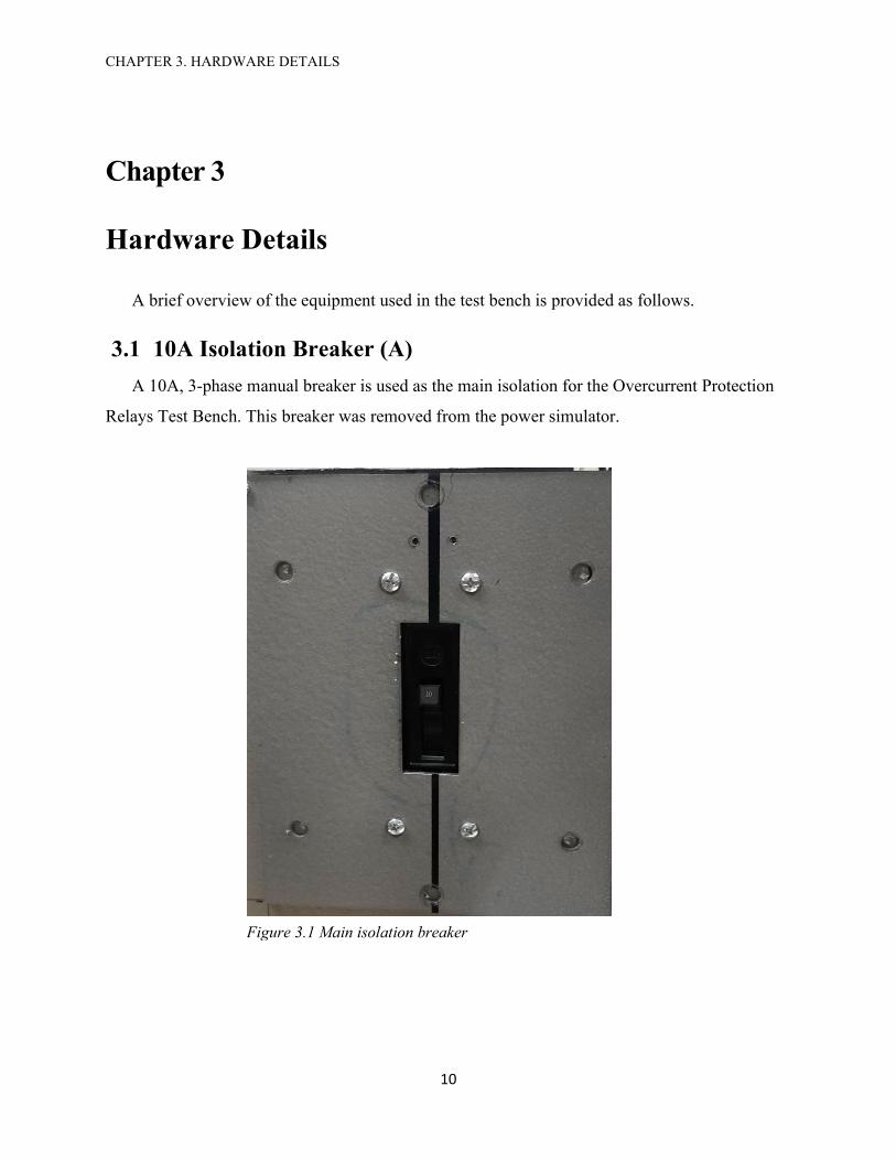
3.1 10A Isolation Breaker (A)
A 10A, 3-phase manual breaker is used as the main isolation for the Overcurrent Protection
Relays Test Bench. This breaker was removed from the power simulator.
Figure 3.1 Main isolation breaker

CHAPTER 3. HARDWARE DETAILS
11
3.2 Transformer Primary Side Protection Breaker Circuit (B)
The circuit of the Overcurrent Protection Relays Test Bench requires two circuit breakers; one
at the primary side and the other at the secondary side of the autotransformer (H). Only one
industrial circuit breaker was available which has been used at the secondary side of the
transformer. For the primary side, a circuit employing solid state relays, 15 VDC power supply,
voltage limiting resistors and a general-purpose double pole double throw (DPDT) relay, has been
designed and used. The functional diagram of the breaker circuit is given in Figure 3.2. The
detailed wiring schematic of breaker circuit is provided in appendix A-2.
S-1 is a general-purpose 12 VDC, DPDT relay which serves as control of the breaker circuit.
S-2, S-3 and S-4 are solid state relays each with one normally open (NO) contact. The NO contacts
of these relays are used as switches for the three phase voltages connected to the primary side of
variable autotransformer (H). DC voltage from a 15VDC power supply is fed to supply points of
S-2, S-3 and S-4 through a toggle switch, which serves as an on/off switch for the breaker, and a
normally closed contact of S-1. The coil of S-1 is connected to the power supply through a voltage
limiting resistance and a parallel combination of output contacts of SEL-751A Feeder Protection
Relay (C1) and three CO-8 electromechanical overcurrent relays (D1, D2 and D3). Voltage supply
to S-1 from either SEL-751A (C1) or CO-8 overcurrent relays (D1, D2 and D3) can be selected
using the cam changeover switch (G1). A NO contact of S-1 is connected in parallel across the
output contacts of relays C1, D1, D2 and D3 and the positive supply going into the coil of S1. This
circuit is completed through a push-button reset switch.
Under normal operation S-2, S-3 and S-4 remain energized through the NC contact of S-1 and
the output contacts of these relays remain close. When a fault is detected by a selected protection
relay, the output contacts of the protection relay will close. This results in voltage being applied to
the coil of S-1. NC contact of S-1 will open and this will cutoff the supply to S-2, S-3 and S-4 and
contacts of these relays will open thereby disconnecting the AC circuit and cause a trip. As the
current level drops, the output contacts of the protection relays will open since these are non-
latching. In this scenario, the supply to the coil of S-1 is maintained through its NO contact. The
breaker can be reset by the push-button reset switch which momentarily disconnects the supply to
S-1. NO contact of S-1 will open and the supply to S-1 will be disconnected. Provided no fault is
detected by the microprocessor protection relay C1 or electromechanical relays D1, D2 or D3

CHAPTER 3. HARDWARE DETAILS
12
(depending on which relay is selected), S-1 will remain disconnected. NC contact of S-1 will close
and provide voltage to S-2, S-3 and S-4 and the AC circuit will be closed.
S-2
S-4
S-3
S-1
S-1NO
S-3NO
S-4NO
S-2NO
S-1NC
Push Button Reset
+ -
Auto Transformer
(VARIAC)
A
B
C
Toggle Switch Manual Trip
15 VDC Power Supply
S-1 DPDT General Purpose RelayS-2, S-3, S-4 Solid State Relays with one Normally Open (NO) ContactS-1 NO Normally Open Contact of S-1S-1 NC Normally Closed Contact of S-1S-1 NO, S-2 NO, S-3 NO Normally Open Contacts of S-1, S-2 and S-3
Voltage Limiting Resistance
From Changeover Cam Switch
AC Wiring
DC Wiring
Output Contacts of Relays
3-phase AC from relays
Figure 3.2 Functional diagram of breaker circuit for transformer primary side protection
Push-button Reset
On/Off Toggle Switch
Figure 3.3 Front and rear view of the breaker circuit used for primary side protection

CHAPTER 3. HARDWARE DETAILS
13
3.3 SEL-751A Feeder Protection Relay (C1 and C2)
This section gives a brief overview of SEL-751A Feeder Protection Relay. Complete
information is available in SEL [2]. The Overcurrent Protection Relays Test Bench utilizes two
SEL-751-A Feeder Protection Relays. Relay C1 is installed on the primary side of the variable
autotransformer. Relay C2 is installed on the secondary side of the variable autotransformer. SEL
[2] presents details about the applications, operation and setup of SEL-751A Feeder Protection
Relay. The relay is versatile and provides a lot of protection features. As per SEL [2] and the setup
menu of relays installed in the bench, the relays can provide protection against instantaneous
overcurrent for phase overcurrent (50P), residual overcurrent (50G), neutral overcurrent (50N),
negative sequence overcurrent (50Q); time overcurrent protection over various curves (both US
and IEC) for phase overcurrent (51P), negative sequence overcurrent (51Q), neutral overcurrent
(51N) and residual overcurrent (51G); voltage protections including undervoltage (27),
overvoltage (59); power factor protection (55); and frequency protection (81). SEL [2] mentions
other protection as well, but here, only those protection features are mentioned that are available
in the setup of the relays installed in the test bench.
The relay can support various communication protocols including SEL communication
protocols (SEL ASCII, SEL Compressed ASCII, SEL Fast Meter, SEL Fast Operate and SEL Fast
SER), DNP3, Modbus and IEC 61850. The device has various ports for EIA-232, EIA-485,
Ethernet and Fiber-Optic communication options. For the test bench, EIA-232 serial
communication through serial port 3 (COM3) has been used. SEL ASCII commands can be issued
using the Terminal in QuickSet software.
SEL-751A has different input and output contacts. The relays installed in the test bench have
3 output contacts (OUT101, OUT102 and OUT103) and 2 input contacts (IN101 and IN102) on
the main card in slot A. OUT101 and OUT102 are normally open. OUT103 has both normally
open and normally closed contacts. Additional 4 inputs (IN301, IN302, IN303 and IN304) and 4
outputs (OUT301, OUT302, OUT303 and OUT304) are available in slot C. The output contacts
can be assigned SEL logic equations. Based on the equation assigned to the output contacts, circuit
breakers can be operated. For tripping against protections, a relay word bit TRIP, related with TR
equation has to be assigned to an output contact. By default, OUT103 is assigned the TRIP relay
word bit.

CHAPTER 3. HARDWARE DETAILS
14
3.3.1. SEL-751A Wiring Details
The wiring done for current, voltage and output contacts for SEL-751A relays used in the
Overcurrent Protection Relays Test Bench are detailed in Table 3.1.
Table 3.1 Details of SEL-751A wiring
Wiring Type Slot Slot Terminal Connections
Current Z
Phase A: incoming = ‘1’; outgoing = ‘2’
Phase B: incoming = ‘3’; outgoing = ‘4’
Phase C: incoming = ‘5’; outgoing = ‘6’
Voltage E
Phase A: ‘1’
Phase B: ‘2’
Phase C: ‘3’
Ground: ‘4’
Output A OUT 103: Connected between ‘7’ and ‘8’
Figure 3.4 SEL-751A Feeder Protection Relay front view
CHAPTER 3. HARDWARE DETAILS
15
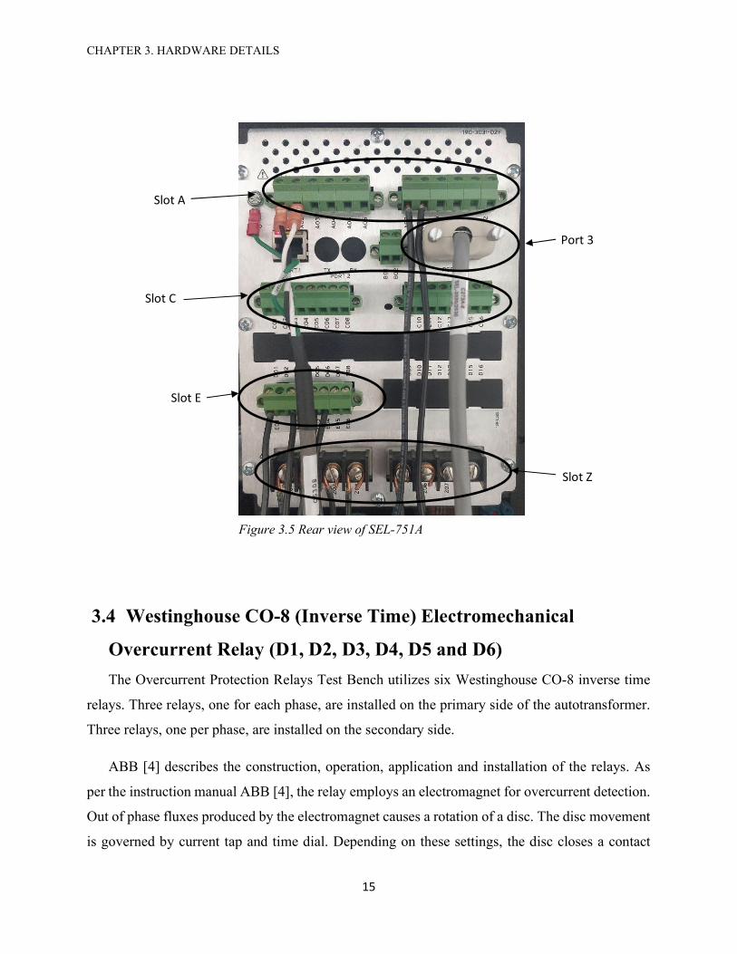
3.4 Westinghouse CO-8 (Inverse Time) Electromechanical
Overcurrent Relay (D1, D2, D3, D4, D5 and D6)
The Overcurrent Protection Relays Test Bench utilizes six Westinghouse CO-8 inverse time
relays. Three relays, one for each phase, are installed on the primary side of the autotransformer.
Three relays, one per phase, are installed on the secondary side.
ABB [4] describes the construction, operation, application and installation of the relays. As
per the instruction manual ABB [4], the relay employs an electromagnet for overcurrent detection.
Out of phase fluxes produced by the electromagnet causes a rotation of a disc. The disc movement
is governed by current tap and time dial. Depending on these settings, the disc closes a contact
Figure 3.5 Rear view of SEL-751A
Slot A
Slot E
Slot Z
Port 3
Slot C

CHAPTER 3. HARDWARE DETAILS
16
which completes the tripping circuit. Tap setting refer to the minimum current that is required to
produce a movement in the disc. The relays utilized in the test bench has tap setting of 0.5, 0.6,
0.8, 1.0, 1.5. 2.0 and 2.5. Tap can be selected by inserting the tap screw at various tap options. This
is located above the time dial. Time dial settings can be changed by moving the time dial in clock
wise or anti clock wise direction. Settings from 0 to 11 are available. The time dial changes the
distance the tripping contact has to travel. Moving from 0 to 11 increases the distance between the
contacts. Tap setting screw and time dial are shown in Figure 3.6.
Figure 3.6 CO-8 Electromechanical overcurrent protection relay
Tap setting screw
Time Dial

CHAPTER 3. HARDWARE DETAILS
17
The wiring connection used for using the CO-8 electromechanical overcurrent protection
relay is detailed in Table 3.2 and shown in Figure 3.7.
Table 3.2 Details of CO-8 overcurrent relay
Wiring Type Connection Points
AC current 8 and 9
DC tripping contact 1 and 10
Figure 3.7 Rear view of CO-8 electromechanical overcurrent relay
1
8
9
10

CHAPTER 3. HARDWARE DETAILS
18
3.5 General Electric (GE) AC Voltmeter (E)
A GE 0-300 AC voltmeter has been installed to measure the line to line secondary voltage
applied to load connected at connection ports (J).
3.6. General Electric (GE) AC Ammeter (F)
An AC ammeter has been installed to indicate the current flow at phase-A on the secondary
side of the variable autotransformer.
Figure 3.8 AC voltmeter installed in the test bench
Figure 3.9 AC ammeter installed in the test bench

CHAPTER 3. HARDWARE DETAILS
19
3.7. Primary Side and Secondary Side Changeover Switches (G1
and G2)
Cam Changeover switches have been installed in the primary side (G1) and secondary side
(G2) of the variable autotransformer. The changeover switches on either side of the transformer
select SEL-751A or electromechanical Westinghouse CO-8 relays installed on these sides. The
selector switches have three position. If the selector knob is turned to position ‘1’ then current and
circuit breaker tripping paths are established through SEL-751A relays. If the selector knob is
turned to position ‘2’ then current and circuit breaker tripping paths are made through
electromechanical relays. Selecting ‘0’ will disconnect both types of relays.
3.8. Variable Autotransformer - VARIAC (H)
A 3-phase variable autotransformer (General Radio Company VARIAC) is used to provide
voltage to the load that can be connected to the secondary side of the transformer through load
connecting ports. The primary side is supplied with 3 phase 208 VLL, 60 Hz voltage supply. The
secondary voltage can be adjusted from ‘0’ to a maximum of 208 VLL by using the knob shown
in Figure 3.8.1. Turning the knob clockwise, increases the voltage and turning it counter
clockwise will reduce the secondary voltage. The transformer is rated at 240 VAC, 4 A at 50-60
Hz.
Figure 3.10 Cam changeover switch front and rear view

CHAPTER 3. HARDWARE DETAILS
20
The primary and secondary windings are connected in wye configuration. The primary side is
connected at connection point ‘4’. The secondary side connection is made at connection point ‘3’.
The common neutral connection is made at ‘2’.
3.9. GE Industrial Circuit Breaker for Transformer Secondary
Protection (I)
The secondary circuit is connected through a GE Industrial Circuit Breaker. The breaker was
removed from the power simulator. The breaker can be turned on or off by the breaker handle. The
tripping circuit of the breaker requires 125 VDC and 1 A current. When the breaker is tripped, the
handle will move to position in between the on (handle all the way up) and off (handle all the way
down). The breaker is reset by moving the handle from the tripped position to off position and then
to on position.
Figure 3.11 Variable autotransformer front view and rear view. Voltage can be adjusted with the knob
3 For secondary
connection
2 For common connection
4 For primary connection
CHAPTER 3. HARDWARE DETAILS
21
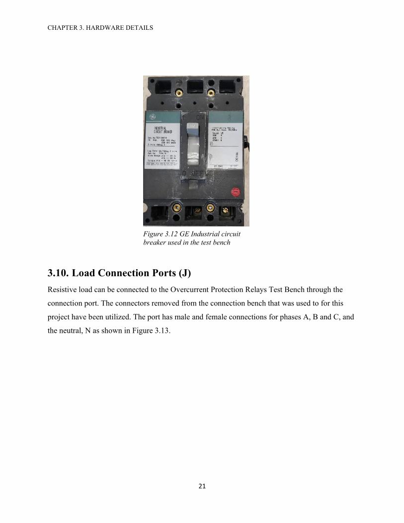
3.10. Load Connection Ports (J)
Resistive load can be connected to the Overcurrent Protection Relays Test Bench through the
connection port. The connectors removed from the connection bench that was used to for this
project have been utilized. The port has male and female connections for phases A, B and C, and
the neutral, N as shown in Figure 3.13.
Figure 3.12 GE Industrial circuit breaker used in the test bench

CHAPTER 3. HARDWARE DETAILS
22
3.11. Full Wave Bridge Rectifier Circuit
In order to provide the appropriate DC voltage to operate the tripping mechanism of the industrial
breaker (I) installed at the secondary of the variable autotransformer, a bridge rectifier circuit has been used.
The schematic of the bridge rectifier circuit is presented in Figure 3.14.
120 VAC, 60 Hz 100 uF 100 uF 100 uF100 uF 100 uF 100 uF
50 Ω
Breaker Trip Coil
Figure 3.14 Schematic of bridge rectifier circuit for the industrial circuit breaker
The circuit employs a bridge rectifier diode for full rectification of single-phase AC voltage
input. Six 100μF electrolytic capacitors are used for reducing the ripple voltage. A 50Ω resistance
has been used to limit the output voltage to around 125 VDC. The value of resistor used was
determined by noting the no load voltage of the rectifier circuit (nearly 175 VDC) and measuring
Figure 3.13 Load connection ports.
Phase A male and female connectors
Phase B male and female connectors
Phase C male and female connectors
Neutral male and female connectors

CHAPTER 3. HARDWARE DETAILS
23
the resistance of the tripping circuit of the breaker (around 125 Ω). Since the voltage is applied
momentarily a resistance has been included to keep the maximum value of the voltage under 125
VDC.
Figure 3.15 Full wave rectifier circuit used in the test bench

CHAPTER 4. SEL FEEDER PROTECTION RELAY COMMUNICATION AND MONITORING SETUP
24
Chapter 4
SEL Feeder Protection Relay Communication and
Monitoring Setup
The overall communication setup for SEL 751-A Feeder Protection Relays employed in the
test bench for demonstrating the application of microprocessor-based overcurrent relay protection
and SEL-387A Current Differential Relay that can be used for demonstrating the application of
microprocessor-based differential current protection relay, is shown in Figure 4.1. The SEL-751A
Feeder Protection Relays, used in the Overcurrent Protection Relays Test Bench, can be configured
and monitored conveniently with ACSELERATOR QuickSet® SEL-5030 software. ACSELERATOR
QuickSet® SEL-5030 software provides the options of using serial, network or modem
connections. For the test bench, the relays are connected to the SEL-3351 Computing Platform by
using serial ports on these devices. The Computing Platform is connected to Personal Computer
(PC) with crossover ethernet cable. Communication between SEL relays and ACSELERATOR
QuickSet® is done by serial to network conversion using SubstationSERVER.NET installed on the
SEL-3351 Computing Platform. SubstationSERVER.NET supports various communication
protocols. For this application, Port Server supported by SubstationSERVER.NET enables
ACSELERATOR QuickSet® to access the serial ports on the computing platform through Ethernet
connection.

CHAPTER 4. SEL FEEDER PROTECTION RELAY COMMUNICATION AND MONITORING SETUP
25
SEL-387A CURRENT DIFFERENTIAL RELAY(Not part of the Overcurrent Relay Test Bench)
Personal Computer (PC)
running SEL ACSELERATOR
QuickSet
Ethernet Connection (Cross over cable)
SEL-751A FEEDER
PROTECTION RELAY
SEL-751A FEEDER
PROTECTION RELAY
SEL 3351 COMPUTING PLATFORM
Serial Communication
Serial Communication
Serial Communication
COM 2 COM 3 COM 4
COM 3 COM 3
Figure 4.1. Communication set up for SEL microprocessor-based relays.

CHAPTER 4. SEL FEEDER PROTECTION RELAY COMMUNICATION AND MONITORING SETUP
26
The procedure used in this project for configuring and monitoring SEL relays is outlined in
figure 4.2.
Figure 4.2. Procedure employed for configuring and monitoring SEL relays
Hardware Connections Connect hardware according to
figure 4.1
Ethernet Connection Establish Ethernet connection
between PC and SEL-3351 Computing Platform
Substation SERVER.NET Configure SubstationSERVER.NET on SEL-3351 Computing
Platform for Port Server operation. Start Port Server services.
AcSELerator QuickSet Setup Run ACSELERATOR QuickSet on the PC. Configure data base.
Access individual relays via QuickSet Terminal and setup each relay according to the application/requirements.
Monitor Monitor relay data using HMI in QuickSet
SEL-751A Setup Setup the relay protection settings with
QuickSet

CHAPTER 4. SEL FEEDER PROTECTION RELAY COMMUNICATION AND MONITORING SETUP
27
4.1. Hardware Connections The hardware connection is done as per Figure 4.1. Lab PC is connected to SEL-3351
Computing Platform via Ethernet crossover cable. SEL-751A Feeder Protection Relays are
connected to SEL-3351 Computing Platform using serial ports on these devices and SEL serial
cables. COM port 3 on SEL-751A has been utilized. On the Computing Platform, COM ports on
the rear side have been utilized. Computing Platform has 16 serial ports for connecting devices.
For the overcurrent relay test bench, COM2 has been configured for connecting relay used for
transformer primary protection. COM 3 has been connected with the relay that is employed for
feeder (load) protection. COM4 has been configured to connect SEL-387A Current Differential
Relay which can be used in the test bench proposed for demonstrating current differential
protection relay (Chapter 5).
4.2. Establishing Ethernet Connection between PC and SEL-3351
Computing Platform
After the hardware is connected, Ethernet connection has to be established between the lab PC
and SEL-3351 Computing Platform. For this purpose, IP addresses have to be assigned to both the
PC and the Computing Platform. This is first done for the lab PC. As both the lab PC and the
Computing Platform are running Windows XP, the procedure is similar. The steps are outlined as
follows.
CHAPTER 4. SEL FEEDER PROTECTION RELAY COMMUNICATION AND MONITORING SETUP
28
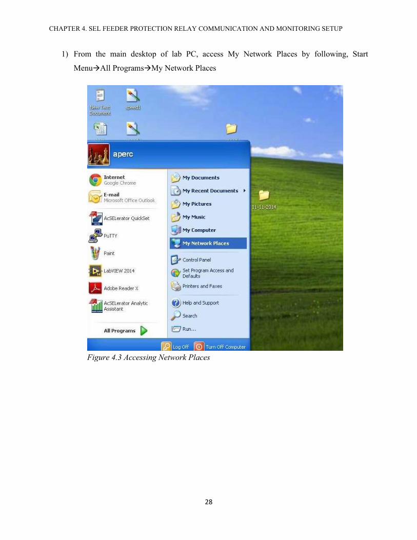
1) From the main desktop of lab PC, access My Network Places by following, Start
MenuAll ProgramsMy Network Places
Figure 4.3 Accessing Network Places

CHAPTER 4. SEL FEEDER PROTECTION RELAY COMMUNICATION AND MONITORING SETUP
29
2) Click View network connections (Figure 4.4)
Figure 4.4 Network Connections

CHAPTER 4. SEL FEEDER PROTECTION RELAY COMMUNICATION AND MONITORING SETUP
30
3) Right Click on Local Area Connection and select Properties
Figure 4.5 Network Properties

CHAPTER 4. SEL FEEDER PROTECTION RELAY COMMUNICATION AND MONITORING SETUP
31
4) From the window that appears, select Internet Protocol (TCP/IP). A window will appear.
Enter IP address as shown
The IP address settings used for Lab PC and SEL-3351 Computing Platform are given in
the following Table 4.1.
Table 4.1 IP properties used for PC with QuickSet and SEL-3351 Computing Platform
PC
IP Address 192.168.56.1
Subnet Mask 255.255.255.0
Default Gateway . . . . (left blank)
SEL-3351 Computing Platform
IP Address 192.168.56.2
Subnet Mask 255.255.255.0
Default Gateway . . . . (left blank)
Figure 4.6 Accessing IP properties

CHAPTER 4. SEL FEEDER PROTECTION RELAY COMMUNICATION AND MONITORING SETUP
32
Important- First three fields of the IP address should match. The last number in the IP
address should be different for PC and Computing Platform.
The procedure described above can be used to assign IP address to the SEL-3351 Computing
Platform. Once the IP address are set, the connection between the PC and Computing Platform can
be checked by issuing a ping in command prompt from either machine. If the PC is used to verify
the connection then Computing Platform should be pinged (ping IP address of Computing Platform
i.e. ping 192.168.56.2).
4.3. SubstationSERVER.NET Setup
Once the Ethernet connection has been established, the communication of SEL relays with PC
running ACSELERATOR QuickSet software has to be established. This can be done using
SubstationSERVER.NET software on SEL-3351 Computing Platform. SubstationSERVER.NET
provides protocol translation, SUBNET [5].
The manufacturer’s guide listed at SUBNET [5] details capabilities of the software. Here only
those aspects which are pertinent to this project are described. The software can be launched from
the software’s icon on the desktop of SEL-3351 Computing Platform.
Figure 4.7 SubstationSERVER.NET

CHAPTER 4. SEL FEEDER PROTECTION RELAY COMMUNICATION AND MONITORING SETUP
33
When the software is launched a screen similar to the one indicated in Figure 4.7 will appear.
The left pane shows the various protocols supported by SubstationSERVER.NET. The center pane
lists the devices and ports configured for each supported protocol. New ports can be configured on
this pane. The right side shows the properties associated with a port (i.e. Ethernet port or serial
COM port) when the port is selected for a particular protocol listed on the left pane.
Some of the pertinent protocols and applications supported by SubstationSERVER.NET
installed on the Computing Platform are listed in the Table 4.2.
Table 4.2 Protocols supported by SubstationSERVER.NET installed on the Computing Platform
Master Protocols
DNP3
Modbus
SEL Fast Messaging (For SEL devices)
Slave Protocols DNP3
Modbus
Enterprise Applications Port Server
Event File Collection SEL ASCII
Modbus or DNP3 protocols are widely used in industry for connecting field devices like relays
to third party applications. However, for this project the SEL-751A relays, used in the Overcurrent
Protection Relays Test Bench, have been configured to work with SEL ACSELERATOR QuickSet.
For this purpose, Port Server under Enterprise Applications in SubstationSERVER.NET can be
utilized to connect SEL relays with ACSELERATOR QuickSet. The COM ports, which have to be
accessed (ports where relays are connected), need to be defined and configured. The configuration
of COM port involves entering information such as baud rate, byte size, parity and stop bits. To
demonstrate the detailed configuration of serial COM port on the Computing Platform for
communication with QuickSet software, the process for serial port 5 is shown. For this example,
a spare SEL-751A relay connected to COM5 port is used, which is not a part of the overcurrent
relay testing bench. COM2 (for SEL-751A Feeder Protection Relay used for primary side
protection of autotransformer), COM3 (for SEL-751A Feeder Protection Relay used for load or
feeder protection), and COM4 (for SEL-387A for current differential protection) have been
configured in the same manner as illustrated below.

CHAPTER 4. SEL FEEDER PROTECTION RELAY COMMUNICATION AND MONITORING SETUP
34
Double Click on SSNET Explorer icon to launch SubstationSERVER.NET
Figure 4.8 Computing Platform Desktop with SSNET Explorer icon
1) Launch SubstationSERVER.NET from its desktop icon on the Computing Platform
CHAPTER 4. SEL FEEDER PROTECTION RELAY COMMUNICATION AND MONITORING SETUP
35
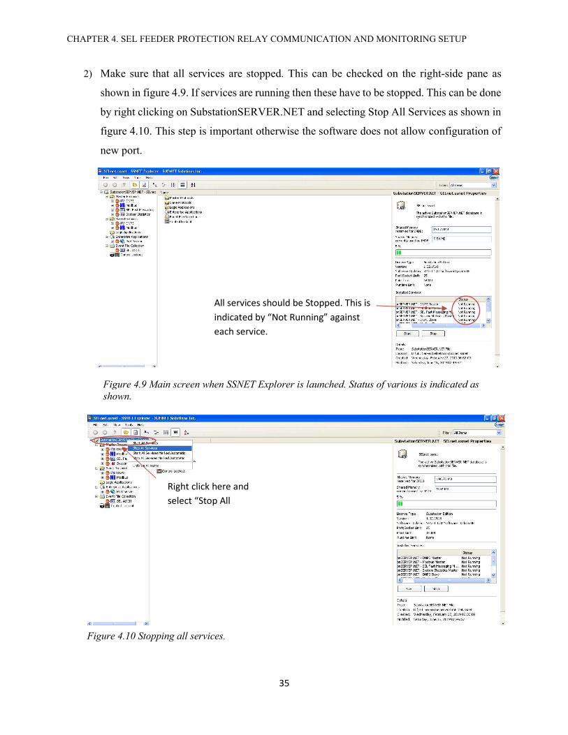
2) Make sure that all services are stopped. This can be checked on the right-side pane as
shown in figure 4.9. If services are running then these have to be stopped. This can be done
by right clicking on SubstationSERVER.NET and selecting Stop All Services as shown in
figure 4.10. This step is important otherwise the software does not allow configuration of
new port.
Figure 4.10 Stopping all services.
Right click here and select “Stop All
Figure 4.9 Main screen when SSNET Explorer is launched. Status of various is indicated as shown.
All services should be Stopped. This is indicated by “Not Running” against each service.
CHAPTER 4. SEL FEEDER PROTECTION RELAY COMMUNICATION AND MONITORING SETUP
36
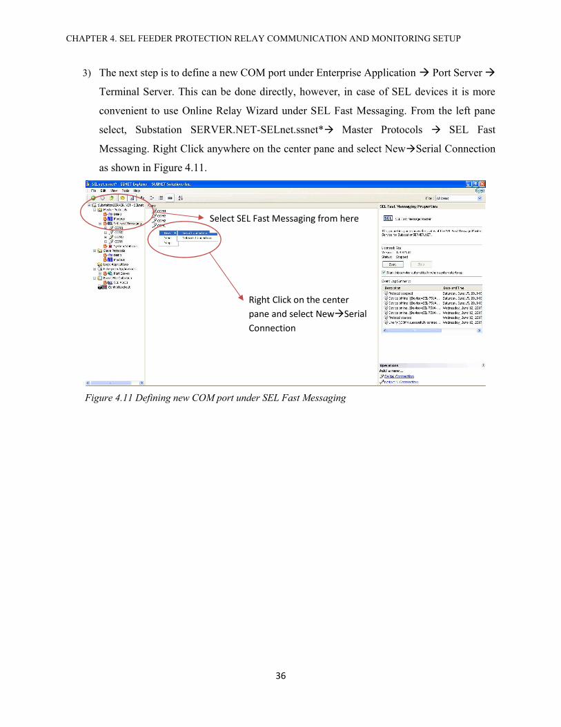
3) The next step is to define a new COM port under Enterprise Application Port Server
Terminal Server. This can be done directly, however, in case of SEL devices it is more
convenient to use Online Relay Wizard under SEL Fast Messaging. From the left pane
select, Substation SERVER.NET-SELnet.ssnet* Master Protocols SEL Fast
Messaging. Right Click anywhere on the center pane and select NewSerial Connection
as shown in Figure 4.11.
Figure 4.11 Defining new COM port under SEL Fast Messaging
Select SEL Fast Messaging from here
Right Click on the center pane and select NewSerial Connection

CHAPTER 4. SEL FEEDER PROTECTION RELAY COMMUNICATION AND MONITORING SETUP
37
4) A new COM is given a default name of COM1. This name should be changed according
to the port being used to connect the device with the Computing Platform. For this example,
we are using serial port 5 so we name it COM5 as shown in Figure 4.12.
Newly created serial port has a default name of COM1. The name is changed from here.
Figure 4.12 Renaming serial COM port

CHAPTER 4. SEL FEEDER PROTECTION RELAY COMMUNICATION AND MONITORING SETUP
38
5) Click on the name of newly created COM port. This will open properties of COM port on
the right pane. It is important to know the baud rate, byte size, parity and stop bits. These
settings can be checked against default settings described in SEL device manuals or directly
checked from a device using front panel keys. For this example, a SEL-751A with
following properties is configured.
Table 4.3 Serial Properties for SEL-751A
Property Description Value/Setting used
in this example
Port Number
This is usually number of the serial port on the Computing Platform. We are configuring COM 5. So, we select 5 here.
5
Baud Rate This is baud of the device (relay) being connected. 9600 Byte Size Byte size selected for the relay 8
Parity Parity being used by the device for serial communication
none
Byte Size Byte Size being used by the device for serial communication
1
RTS Line Request to Send Constant CTS Line Clear to Send Check
Figure 4.13 COM port configuration
1. Click on the name of newly created COM port 2. Enter the serial
port properties here

CHAPTER 4. SEL FEEDER PROTECTION RELAY COMMUNICATION AND MONITORING SETUP
39
6) After configuring the serial COM properties, Online Relay Wizard (on the lower side of
right pane) has to be launched. This will open a window as shown in Figure 4.14. Enter
level 1 password of relay being connected and click Connect.
Once autoconfiguration is complete, click Finish.
Figure 4.15 Successful completion of auto configuration
Figure 4.14 Starting the Online Relay Wizard
Click on Online Relay Wizard
Enter Level 1 Password of relay being connected
Click on Connect

CHAPTER 4. SEL FEEDER PROTECTION RELAY COMMUNICATION AND MONITORING SETUP
40
7) Access Terminal Server from the left pane by selecting,
Substation SERVER.NET-SELnet.ssnet* Enterprise Applications Port Server
Terminal Server
Right click on the center pane and select New Serial Port.
Figure 4.16 Defining serial COM port under Terminal Server

CHAPTER 4. SEL FEEDER PROTECTION RELAY COMMUNICATION AND MONITORING SETUP
41
8) Rename the newly created COM port to COM5 (same name as given in step 4). See Figure
4.17.
When a COM port is created it has a default name of COM1. We have to change the name according to the physical port on Computing Platform. In this example we are using port 5 so we change the name to COM5
Figure 4.17 Changing the name of newly defined COM port

CHAPTER 4. SEL FEEDER PROTECTION RELAY COMMUNICATION AND MONITORING SETUP
42
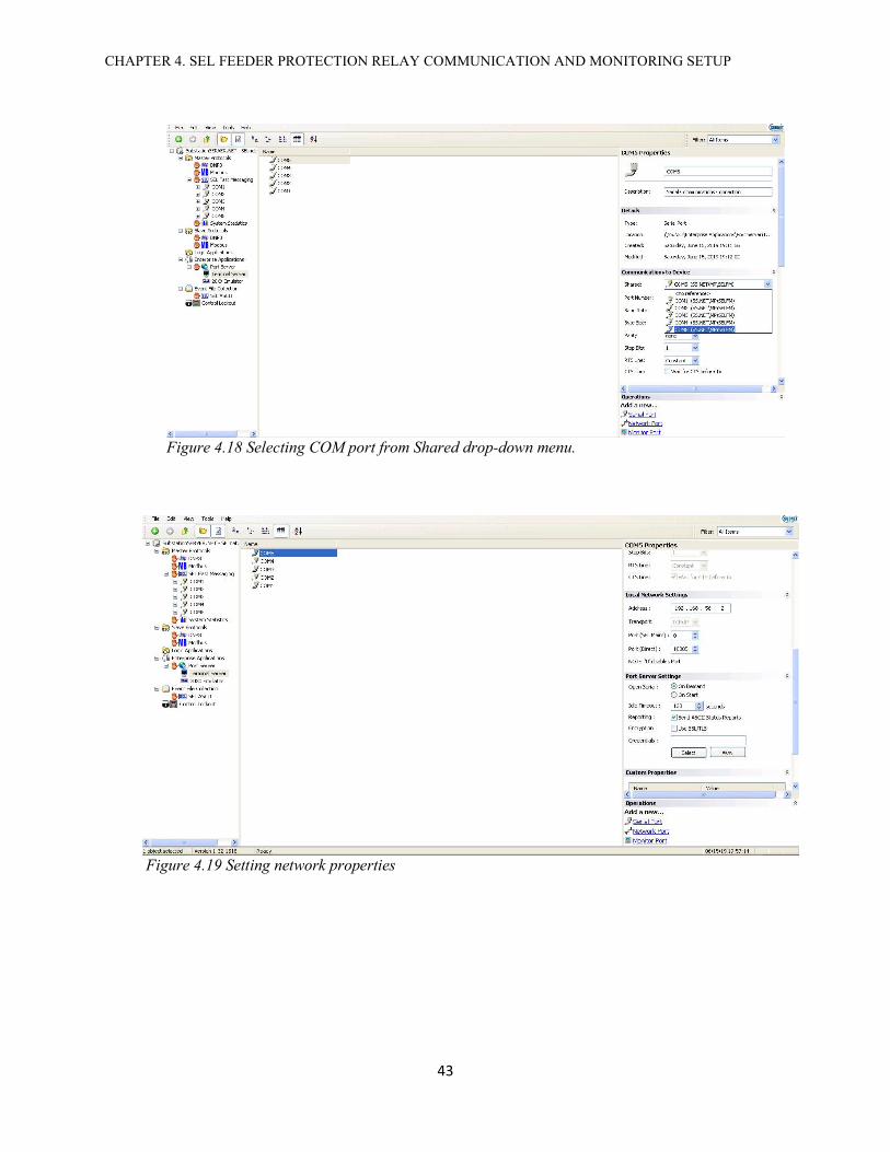
9) Under COM properties (right pane), following parameters are set. These are indicated in Figure
4.18 and 4.19. The properties not described in the Table 4.4, are left at default settings.
Table 4.4 Configuration of COM properties
COM Properties Settings Description Setting/Value
Used
Communications to Device
Shared
This option will import serial port settings directly instead of entering them manually. Since we have already imported device setting by defining COM5 under SEL Fast Messaging (Steps 1-6), we can share serial port settings by selecting COM5. This will link COM5 defined under Terminal Server to COM5 defined under SEL Fast Messaging
COM5
Local Network Settings
Address Enter the IP address of Computing Platform
192.168.56.2
Transport Given by default TCP/IP Port
(SEL Maint) Disabled by setting equal to zero 0
Port (Direct) TCP direct port setting. We are using a format 100xx, where xx represents the port number. In our example xx=05
10005
CHAPTER 4. SEL FEEDER PROTECTION RELAY COMMUNICATION AND MONITORING SETUP
43
Figure 4.18 Selecting COM port from Shared drop-down menu.
Figure 4.19 Setting network properties
CHAPTER 4. SEL FEEDER PROTECTION RELAY COMMUNICATION AND MONITORING SETUP
44
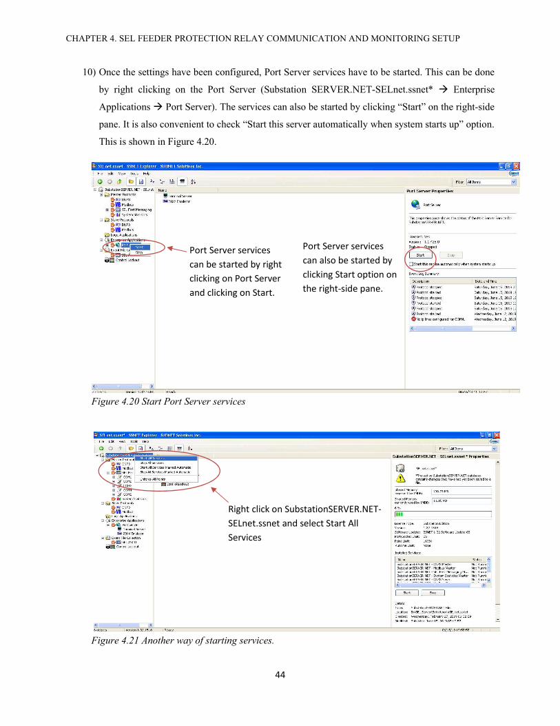
10) Once the settings have been configured, Port Server services have to be started. This can be done
by right clicking on the Port Server (Substation SERVER.NET-SELnet.ssnet* Enterprise
Applications Port Server). The services can also be started by clicking “Start” on the right-side
pane. It is also convenient to check “Start this server automatically when system starts up” option.
This is shown in Figure 4.20.
Services can also be started as shown in Figure 4.3.14.
Port Server services can be started by right clicking on Port Server and clicking on Start.
Port Server services can also be started by clicking Start option on the right-side pane.
Figure 4.20 Start Port Server services
Right click on SubstationSERVER.NET-SELnet.ssnet and select Start All Services
Figure 4.21 Another way of starting services.
CHAPTER 4. SEL FEEDER PROTECTION RELAY COMMUNICATION AND MONITORING SETUP
45
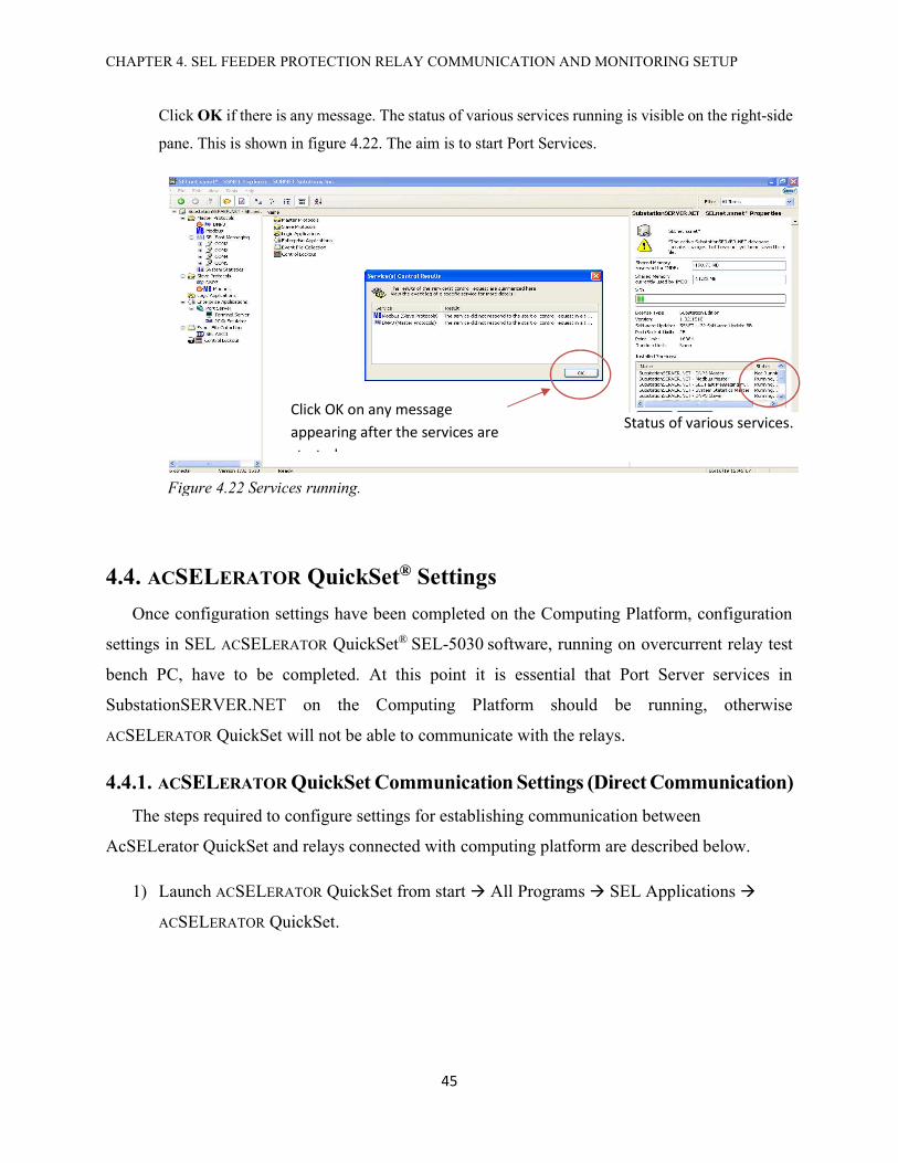
Click OK if there is any message. The status of various services running is visible on the right-side
pane. This is shown in figure 4.22. The aim is to start Port Services.
4.4. ACSELERATOR QuickSet® Settings
Once configuration settings have been completed on the Computing Platform, configuration
settings in SEL ACSELERATOR QuickSet® SEL-5030 software, running on overcurrent relay test
bench PC, have to be completed. At this point it is essential that Port Server services in
SubstationSERVER.NET on the Computing Platform should be running, otherwise
ACSELERATOR QuickSet will not be able to communicate with the relays.
4.4.1. ACSELERATOR QuickSet Communication Settings (Direct Communication)
The steps required to configure settings for establishing communication between
AcSELerator QuickSet and relays connected with computing platform are described below.
1) Launch ACSELERATOR QuickSet from start All Programs SEL Applications
ACSELERATOR QuickSet.
Figure 4.22 Services running.
Click OK on any message appearing after the services are started.
Status of various services.

CHAPTER 4. SEL FEEDER PROTECTION RELAY COMMUNICATION AND MONITORING SETUP
46
Figure 4.23 Launching QuickSet

CHAPTER 4. SEL FEEDER PROTECTION RELAY COMMUNICATION AND MONITORING SETUP
47
2) From the main menu go to Communications Parameters as shown in Figure 4.24.
Figure 4.24 Accessing communication parameters from the main menu.

CHAPTER 4. SEL FEEDER PROTECTION RELAY COMMUNICATION AND MONITORING SETUP
48
3) Use the following setting in the Communication Parameters to configure COM5 port on
Computing Platform as shown in Figure 4.25.
Figure 4.25 Setting communication parameters in QuickSet
These are Level One and Level Two passwords of SEL devices. Usually default password are provided and don’t have to be entered. For SEL-751A default Level One password is OTTER and Level Two password is TAIL
Select File Transfer Option Raw TCP
The format used for port number is 100xx. Since we are configuring COM5 so Port Number is 10005
In Host IP Address enter the IP address of the Computing Platform. We have set the IP address of Computing Platform as 192.168.56.2
Select Active Connection Type Network

CHAPTER 4. SEL FEEDER PROTECTION RELAY COMMUNICATION AND MONITORING SETUP
49
4) Once the communication between relay and acSELerator QuickSet is successfully
established, the lower portion will state the condition Connected and also list the
communication parameters. To ensure that successful communication open Terminal by
clicking on its icon on the main menu. When terminal window is opened, and = sign will
appear. Type ACC. If communication is established, the Terminal will prompt for Level
One password of device (in this case SEL 751-A relay). This is shown in Figure 4.26.
Launch Terminal by clicking this icon
Communication status
Figure 4.26 Confirming successful communication in QuickSet

CHAPTER 4. SEL FEEDER PROTECTION RELAY COMMUNICATION AND MONITORING SETUP
50
4.4.2. ACSELERATOR QuickSet® Communication Settings (Through Database)
Section 4.4.1 described the process of establishing direct communication with a SEL device.
It is, however, more convenient to use ACSELERATOR QuickSet Database to configure a device.
This allows for configuring different devices and save the individual settings of these settings. The
default database is Relay.rdb. Once the settings are saved in the database, then it becomes very
easy to connect to a device. The process is shown as follows.
1) From the main menu select Tools Device Manager Devices. The Device Manager
option is also available on the main display when ACSELERATOR QuickSet is first
launched. A window shown in Figure 4.27 will appear. In the field where password is
required, enter the password of the database. The password of the default database in
QuickSet installed in the lab PC is aperc.
Figure 4.27 Access to ACSELERATOR Database

CHAPTER 4. SEL FEEDER PROTECTION RELAY COMMUNICATION AND MONITORING SETUP
51
2) When the database is opened the folders defined in the database are shown on the left pane
under Connection Explorer. Since a SEL-751A Feeder Protection Relay is being added,
the configuration is added in Overcurrent Relay folder. This is done by right clicking on
the folder name and then selecting Add and then Device as shown in Figure 4.28. A
window, shown in figure 4.29, will appear. Select SEL-751A.
Figure 4.28 Adding a new device in the database
Figure 4.29 Selecting Device Type

CHAPTER 4. SEL FEEDER PROTECTION RELAY COMMUNICATION AND MONITORING SETUP
52
3) Once the device is selected, the name of device is added under folder tree. Clicking on the
device name will open a new window where properties of the device can be configured.
This is shown in Figure 4.30. Select Connection and then click on Edit on the lower right
corner.
1) Click on the device name
2) Click Connection 3) Click Edit
Figure 4.30 Accessing device properties

CHAPTER 4. SEL FEEDER PROTECTION RELAY COMMUNICATION AND MONITORING SETUP
53
4) Enter the communication properties as shown in Figure 4.31
Figure 4.31 Entering communication parameters.
Host IP address: IP address of Computing Platform. 192.168.56.2
Port Number: TCP/IP port number. Format used is 100xx, where xx is the COM port number. 10005
File Transfer Option: Raw TCP

CHAPTER 4. SEL FEEDER PROTECTION RELAY COMMUNICATION AND MONITORING SETUP
54
5) Once the communication parameters for the device are set, then the connection with device
is made by right clicking on the device name under folder name on the left-pane. The first
option on the window that appears ‘Connect’ is then selected. This is shown in Figure 4.32.
Figure 4.32 Connecting a relay with QuickSet

CHAPTER 4. SEL FEEDER PROTECTION RELAY COMMUNICATION AND MONITORING SETUP
55
6) Once connection parameters of a device are defined, it becomes easier to connect the
device. Save any changes if prompted to do so. To connect to a defined device requires
only to right click on the device name and select ‘Connect’ as described in the previous
step. A connected device can be disconnected in the same way. When a device is connected,
the device name will have a green dot. Right clicking on the device name will give the
option of ‘Disconnect’. A disconnected device will have a grey dot followed by the device
name. When the device name is selected the dot turns blue.
When the device is connected the device name will have a green dot.
Figure 4.33 Connected device

CHAPTER 4. SEL FEEDER PROTECTION RELAY COMMUNICATION AND MONITORING SETUP
56
4.5. SEL 751-A Feeder Protection Relay Settings
SEL-751A device settings can be read and modified either by accessing a device with
QuickSet, or by accessing the settings directly using a terminal emulator. QuickSet has a
“Terminal” option available which can be used for this purpose.
The following describes how device settings can be accessed and modified with the above-
mentioned options.
4.5.1. Accessing and Modifying SEL Relays Settings with QuickSet
AcSELerator QuickSet provides option of reading data of a relay that is connected. Once the
data from a device is obtained, it can be modified and sent to the device. This is described as
follows,
1) Connect a relay with QuickSet as described in 4.4.1 or 4.4.2.
2) Click on the “Read Settings From Device” option from the main menu as shown in Figure
4.5.1.1.
.
Figure 4.34 Reading data from a connected device
Device data can also be read from this option
Read Settings From Device

CHAPTER 4. SEL FEEDER PROTECTION RELAY COMMUNICATION AND MONITORING SETUP
57
3) If the device is connected through the database as described in section 4.4.2, then device
data can also be read as shown in Figure 4.35.
A window as shown in Figure 4.36 will appear indicating that device data is being read.
Right click on the connected device. Select Device Tasks and then Read.
Figure 4.35 Reading device data of a relay configured in database.
Figure 4.36 Device data being read from relay

CHAPTER 4. SEL FEEDER PROTECTION RELAY COMMUNICATION AND MONITORING SETUP
58
4) When the reading process is complete, user can access the settings of the device. Clicking
on a particular setting will open details for each setting option. New values can be entered
as shown in Figure 4.37. Relay protection settings are under Group1 Set1. Logic settings
are under Group 1. Once new settings have been entered, the new values can be sent to the
relay by clicking on the “Send Active Settings” option on the main menu.
Relay settings options can be seen under Group1 on this pane. When a particular category is selected, the details menu under it appears on the right.
Values for a selected setting can be changed. In this case new settings for overcurrent can be entered here.
Once the new settings are entered, these can be sent to the device by “Send Active Settings”
Figure 4.37 Detailed device settings. Settings can be read, modified and sent to device.

CHAPTER 4. SEL FEEDER PROTECTION RELAY COMMUNICATION AND MONITORING SETUP
59
5) The software asks the user which settings have to be sent. If any changes in the protection
are made, then only “Set 1” has to be sent. If any changes in the logic settings are made
under “Logic 1” then only “Logic 1” can be sent. The software offers an option of saving
new settings. Saving settings can be convenient as the same settings can be used later on
without the need of reading the relay data.
Figure 4.39 Relay data can be saved in PC and loaded and sent to relay latter on.
Figure 4.38 Selecting settings to send to the device

CHAPTER 4. SEL FEEDER PROTECTION RELAY COMMUNICATION AND MONITORING SETUP
60
4.5.2. Accessing and Modifying SEL Relays Through Terminal
SEL relays’ settings can also be accessed and modified through a terminal emulator and ASCII
commands. Terminal is available in ACSELERATOR QuickSet® 5030 software. When a device
(SEL-751-A) is connected with ACSELERATOR QuickSet® 5030 software, then Terminal can be
launched from its icon on the main menu. This is shown in figure 4.40.
When the relay is communicating, user can enter commands to access and modify relay
settings. Although, there are three levels to access SEL -751A relay as described in section 7 of
SEL [2], however the two useful levels are ‘level 1’ and ‘level 2’. At level 1, user can view the
settings only and not modify any settings. For modifying (changing value) a setting, user must be
at level 2. Table 4.5 describes the two levels.
Figure 4.40 Launching Terminal from ACSELERATOR QuickSet
Terminal is launched by clicking on its icon
Figure 4.41 Terminal window
= sign with blinking cursor indicates that device is communicating
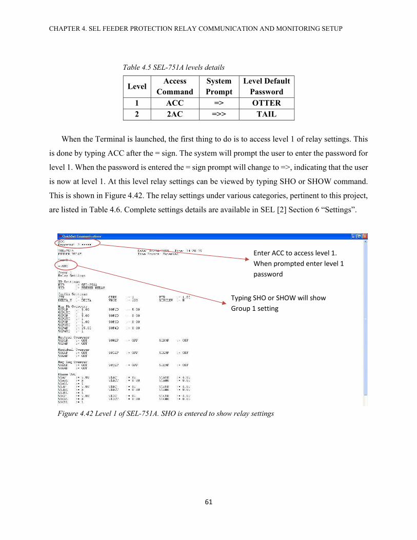
CHAPTER 4. SEL FEEDER PROTECTION RELAY COMMUNICATION AND MONITORING SETUP
61
Table 4.5 SEL-751A levels details
Level Access
Command System Prompt
Level Default Password
1 ACC => OTTER 2 2AC =>> TAIL
When the Terminal is launched, the first thing to do is to access level 1 of relay settings. This
is done by typing ACC after the = sign. The system will prompt the user to enter the password for
level 1. When the password is entered the = sign prompt will change to =>, indicating that the user
is now at level 1. At this level relay settings can be viewed by typing SHO or SHOW command.
This is shown in Figure 4.42. The relay settings under various categories, pertinent to this project,
are listed in Table 4.6. Complete settings details are available in SEL [2] Section 6 “Settings”.
Figure 4.42 Level 1 of SEL-751A. SHO is entered to show relay settings
Enter ACC to access level 1. When prompted enter level 1 password
Typing SHO or SHOW will show Group 1 setting

CHAPTER 4. SEL FEEDER PROTECTION RELAY COMMUNICATION AND MONITORING SETUP
62
Table 4.6 SEL-751A Settings categories pertinent to this project.
Setting Category
Description View Settings SEL
Command Modifying Setting
SEL Command
Date Show/modify the date configured in the device
SHO D SET D
Front Panel Settings
Show/modify device’s front panel settings
SHO F SET F
Global Settings Show/modify Global settings
SHO G SET G
Relay Settings
Show/modify settings under GROUP. This category lists the protection settings of the relay.
SHO SET
Logic Settings
Show/modify settings under LOGIC. This category is important as it lists the relay output assignments.
SHO L SET L
Port Show/modify the settings of relay ports
SHO P x, Where ‘x’ is the port
on the relay. x= 1, 3 or F
SET P x Where ‘x’ is the port on the relay.
x= 1, 3 or F
Report Settings Show/modify Report settings
SHO R SET R
Time Show/modify the relay time settings
SHO T SET T
The settings under each category can be viewed in level 1 or level 2 by typing SEL command
for the required setting, listed in Table 4.6. For example, to view the Logic settings, SHO L is
typed. Similarly, typing SHO will show protection settings of the relay.
In order to modify a setting, a user needs to be in level 2. This can be done by typing 2AC
when user is at level 1. The system will prompt the user for level 2 password. Level 2 is indicated
by prompt =>>. At this level, user can change a setting under a category by typing the commands
listed in Table 4.6 For instance, relay protection settings can be modified by issuing the SET
command in level 2. The device will move through each setting under the category by showing
the present value of the setting followed by a ‘?’. The user has the option to enter a new value for
the setting after ‘?’ and press the “Enter” key to move onto the next setting option. If no
modification is required then “Enter” key should be pressed after the ‘?’. The device will move

CHAPTER 4. SEL FEEDER PROTECTION RELAY COMMUNICATION AND MONITORING SETUP
63
onto to the next setting option. Once all the settings have completed and if modifications have been
made in the settings, the device will ask whether to save the changes or not. Pressing ‘Y’ will save
the changes and pressing ‘N’ will ignore the changes and keep original settings.
The relay settings, which are shown by SHO command and can be modified by SET command,
include configuration settings, various protections settings and trip logic equations which are used
to issue alarm and change the output contacts of the relay to operate connected breakers.
Configuration settings include CT ratio, PT ratio, nominal line to line voltage and transformer
connection settings. The relay offers instantaneous and time- phase, neutral, negative sequence
and residual overcurrent protection; over and undervoltage protection; power factor (pf) lead lag
protection; and frequency variation protection. The protection features can be configured with
different trip levels making the relay versatile in application. These settings also include trip
variables and word bits which can be modified for a customized operation of relay. Important of
these are,
1) TR-which assigns a word bit TR to a logical equation that incorporates the protection
features of the relay. The logical equation uses AND, OR and NOT combinational logic
elements to combine various protection elements. The default TR equation is given by,
Where,
ORED50T= OR output of all instantaneous current protection elements (50)
ORED51T= OR output of all time current protection elements (51)
81D1T= Frequency trip level 1 (81)
81D2T= Frequency trip level 2 (81)
81D3T= Frequency trip level 3 (81)
81D4T= Frequency trip level 4 (81)
59P1T= Level 1 phase overvoltage trip (59)
59P2T= Level 2 phase overvoltage trip (59)
55T= Power factor trip (55)
REMTRIP= Remote Trip
TR: = ORED50T OR ORED51T OR 81D1T OR 81D2T OR 81D3T OR 81D4T OR 59P1T OR 59P2T OR 55T OR REMTRIP OR SV01 OR OC OR SV04T

CHAPTER 4. SEL FEEDER PROTECTION RELAY COMMUNICATION AND MONITORING SETUP
64
SV01= SEL logic variable 1
OC= Breaker open status
SV04T= SEL logic variable 4 timer output
2) ULTRIP- which assigns a variable ULTRIP to a logical equation that incorporates
unlatching feature.
3) REMTRIP- this variable takes into account remote trip options. This is done by assigning
SEL logical equation to REMTRIP variable. It usually involves assigning an input contact
to REMTRIP.
Logic settings include logic enables, latch bit equations, SEL logic variables and more
importantly output contact assignments and can be viewed by SHO L command and modified with
SET L command. The relays’ output contacts, which can be used to annunciate alarm devices or
trip breakers, are assigned under Logic settings. TRIP word bit is associated with trip logic TR
(described in the previous section). Trip settings in TR can be assigned to a contact by assigning
the word TRIP to a contact. By default, TRIP is assigned to OUT103 output contact coil.
One disadvantage with using Terminal for viewing and modifying relay settings is that
complete description of settings is not given and only SEL names of the settings are shown. For a
complete definition of the setting options, section 4 and SEL-751A settings sheets in SEL [2] can
be used. Appendix B lists the definitions of relay settings available in the relays installed in the
test bench.
4.6. Monitoring
The relay readings can be monitored with Human Machine Interface (HMI) in QuickSet.
This can be done with the following steps.
1) Connect relay with QuickSet as described in 4.4.1 or 4.4.2.

CHAPTER 4. SEL FEEDER PROTECTION RELAY COMMUNICATION AND MONITORING SETUP
65
2) Click on the HMI icon on the main menu.
Click on the HMI icon on the menu
Figure 4.43 Accessing the HMI in QuickSet

CHAPTER 4. SEL FEEDER PROTECTION RELAY COMMUNICATION AND MONITORING SETUP
66
3) The software reads the relay data. Once the data is read, the screen shown in Figure 4.44
will appear.
Figure 4.44 Device Overview on HMI
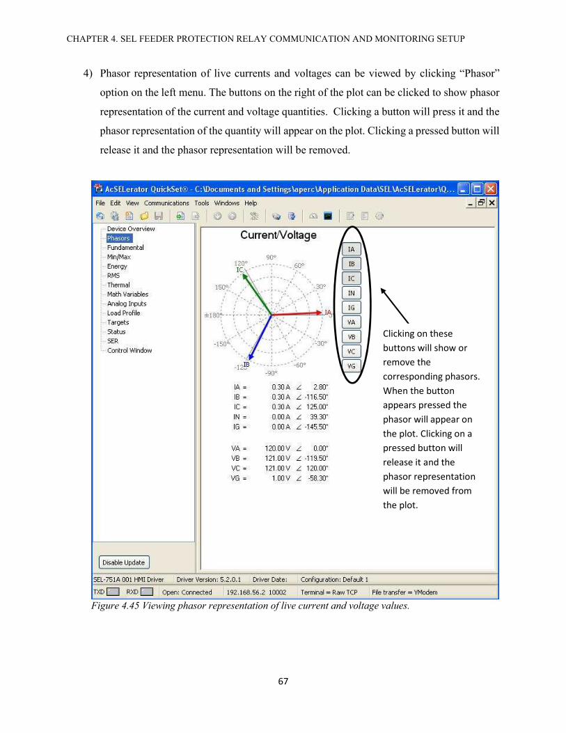
CHAPTER 4. SEL FEEDER PROTECTION RELAY COMMUNICATION AND MONITORING SETUP
67
4) Phasor representation of live currents and voltages can be viewed by clicking “Phasor”
option on the left menu. The buttons on the right of the plot can be clicked to show phasor
representation of the current and voltage quantities. Clicking a button will press it and the
phasor representation of the quantity will appear on the plot. Clicking a pressed button will
release it and the phasor representation will be removed.
Figure 4.45 Viewing phasor representation of live current and voltage values.
Clicking on these buttons will show or remove the corresponding phasors. When the button appears pressed the phasor will appear on the plot. Clicking on a pressed button will release it and the phasor representation will be removed from the plot.

CHAPTER 4. SEL FEEDER PROTECTION RELAY COMMUNICATION AND MONITORING SETUP
68
In the phasor plot,
IA= Current of phase A
IB= Current of phase B
IC= Current of phase C
IN= Current through neutral. As neutral is not connected through the relay, this should be zero.
IG= Phasor sum of IA, IB and IC
VA= Phase voltage of phase A
VB= Phase voltage of phase B
VC= Phase voltage of phase C
VG= Phasor sum of VA, VB and VC
5) Fundamental metering values can be viewed by clicking on “Fundamental” option on the
right pane.
Figure 4.46 Fundamental metering values

CHAPTER 4. SEL FEEDER PROTECTION RELAY COMMUNICATION AND MONITORING SETUP
69
6) Events can be saved and viewed by going to Tools Events Get Events Files, as
shown in Figure 4.47.
7) The software shows a list of events. Event of interest can be selected. After this “Get
Selected Events” button is clicked.
Figure 4.47 Getting Events Files
Figure 4.48 List of events.
After selecting the events listed on the left click this button

CHAPTER 4. SEL FEEDER PROTECTION RELAY COMMUNICATION AND MONITORING SETUP
70
8) Once the software gets the event data, a window to save the Events will open. Select the
folder to event file.
Figure 4.49 Saving Events

CHAPTER 4. SEL FEEDER PROTECTION RELAY COMMUNICATION AND MONITORING SETUP
71
9) From start menu select All Programs SEL Applications AcSELerator Analytic
Assistant.
10) From the file menu select the location of the event file.
Figure 4.50 Opening AcSELerator Analytic Assistant in the lab PC
Figure 4.51 Opening event file in in AcSELerator Analytic Assistant
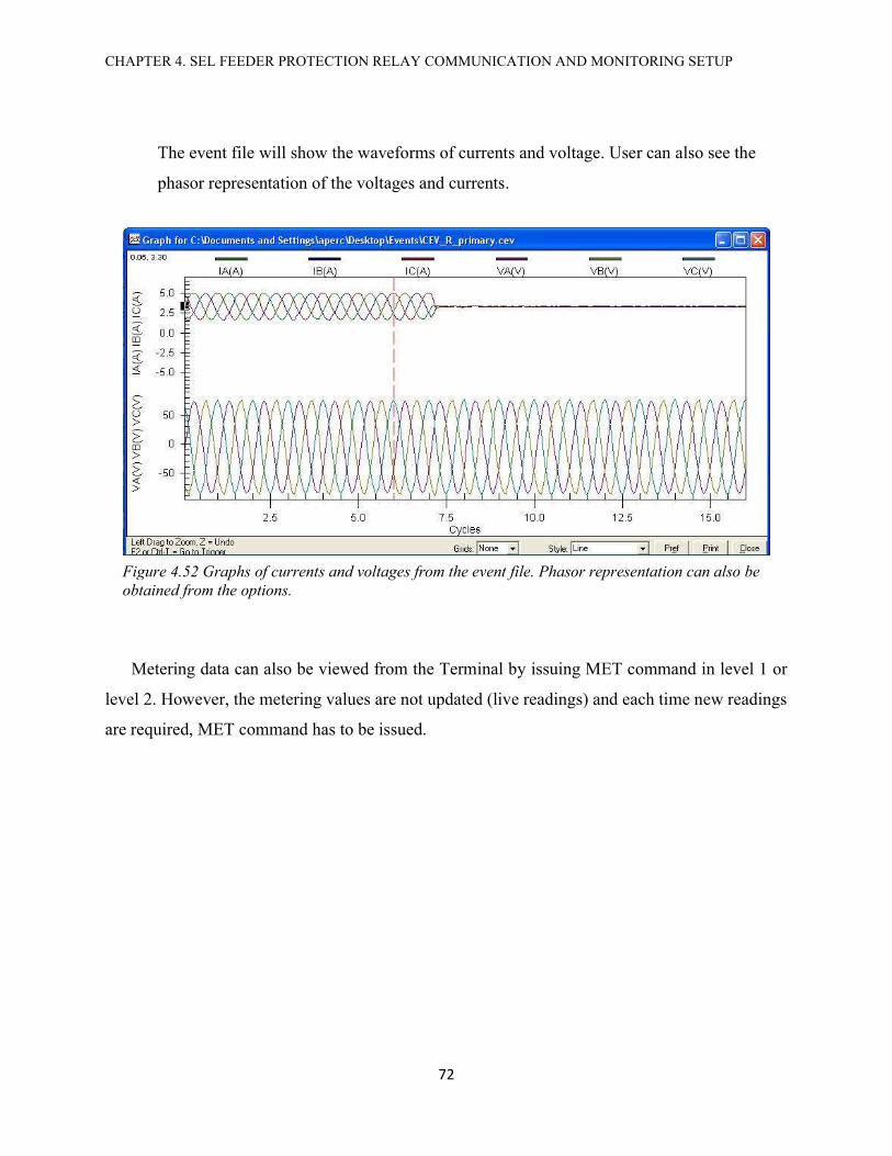
CHAPTER 4. SEL FEEDER PROTECTION RELAY COMMUNICATION AND MONITORING SETUP
72
The event file will show the waveforms of currents and voltage. User can also see the
phasor representation of the voltages and currents.
Metering data can also be viewed from the Terminal by issuing MET command in level 1 or
level 2. However, the metering values are not updated (live readings) and each time new readings
are required, MET command has to be issued.
Figure 4.52 Graphs of currents and voltages from the event file. Phasor representation can also be obtained from the options.

CHAPTER. 5 FUTURE WORK
73
CHAPTER 5
FUTURE WORK
Based on the success of this project, it is planned to build a similar bench for demonstrating
differential current protection. For this purpose, a SEL-387A Current Differential Relay can be
used. Tripping can be achieved with a similar breaker circuit that has been designed and
implemented in this project. The proposed schematic for the Differential Current Protection Relay
Test Bench is given in appendix A3. This circuit was tested with both line to line and line to neutral
faults. The relay was able to detect the imbalance in the currents between the primary and
secondary sides of a variable autotransformer. As a part of this project, the SEL-387A Current
Differential Relay has already been configured with ACSELERATOR QuickSet®.
The proposed design is similar to example given in SEL [6] (figure 2.7 pp 2.10) and uses
SEL-387A relay with a variable autotransformer. The difference in the proposed design is that it
will employ only one breaker circuit, which has been designed in this project, on the primary side
of the transformer. Load connection points for introducing a line to line and a line to neutral fault
will be included on the primary side. The proposed design also will not have its neutral connected
with SEL-387A relay.
As per the suggested design the current differential has its primary (IAW1, IBW1 and
ICW1) and secondary (IAW2, IBW2 and ICW2) pick up elements connected across the
transformer. Three phase loads can be connected through load connection port. Fault creating loads
are connected on the primary side of the autotransformer after IAW1, IBW1 and ICW1. When a
fault is introduced, it will create an imbalance between the current flowing through the primary
side and secondary pickup elements and the relay will close its contact OUT103 which will trip
the breaker circuit and the connection between the incoming AC supply and primary side of the
variable autotransformer will be broken.
The setup used to test the suggested circuit for the differential current protection is shown in Figure 5.1.
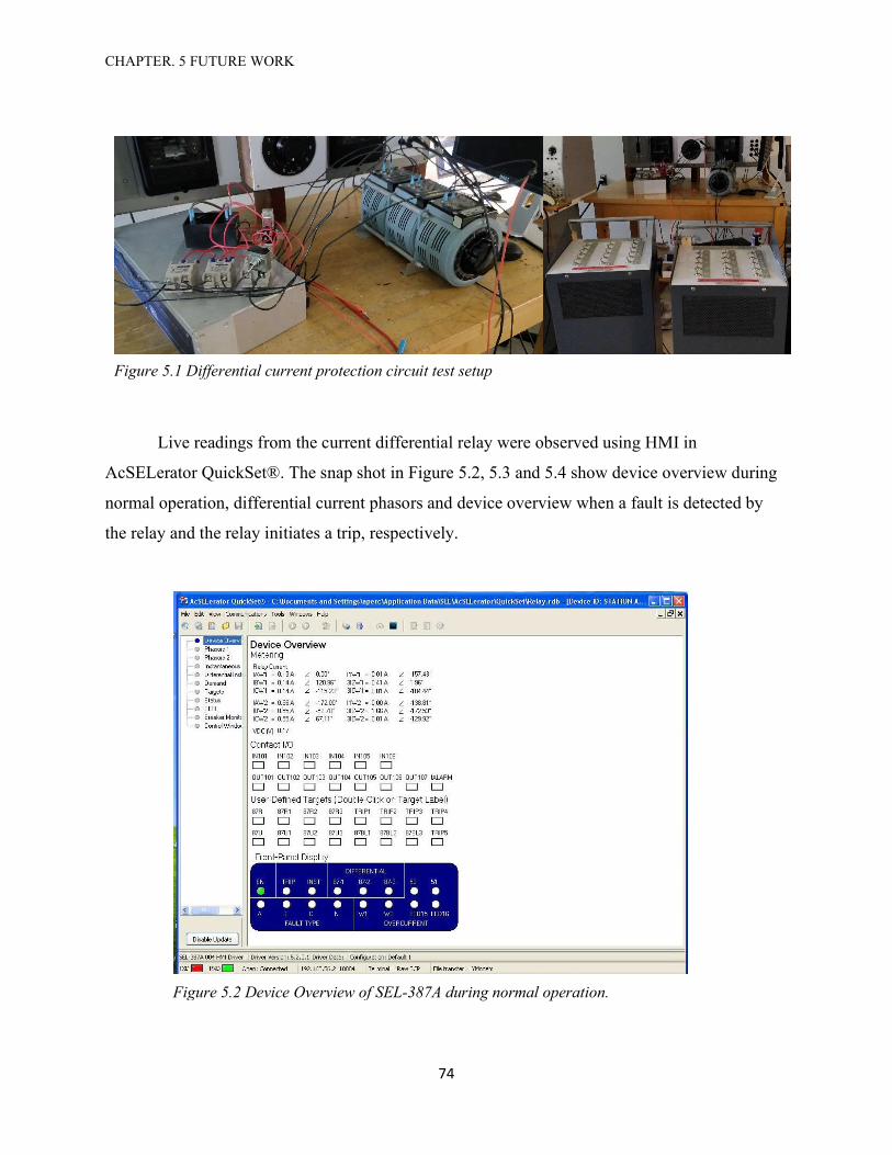
CHAPTER. 5 FUTURE WORK
74
Live readings from the current differential relay were observed using HMI in
AcSELerator QuickSet®. The snap shot in Figure 5.2, 5.3 and 5.4 show device overview during
normal operation, differential current phasors and device overview when a fault is detected by
the relay and the relay initiates a trip, respectively.
Figure 5.1 Differential current protection circuit test setup
Figure 5.2 Device Overview of SEL-387A during normal operation.

CHAPTER. 5 FUTURE WORK
75
Figure 5.3 Phasor representation of differential currents.
Figure 5.3 Device Overview of SEL-387A when relay trips.

76
Appendix
Appendix A- Overcurrent Protection Relays Test Bench Circuit Schematics
Appendix B- SEL -751A Settings Definitions
Appendix C- US Inverse Time Relay Operating Time vs. Multiples of Pick-up
Current
Appendix D- List of Passwords
Appendix E- Parts List

APPENDIX A- CIRCUIT SCHEMATICS
77
10AIsolation Breaker
A B C NA
V
A
E
Z
1 2 3 4 5 6 7 128 9 10 11
SEL 751-A
8 9 1 10
Westinghouse CO-8 Electromechanical Relay
8 9 1 10
8 9 1 10
+ -Breaker Circu it with
15VDC operating and 12VDC control. (Detailed
schematic in sheet 2)
+
-
1 2 3 4 5 6
A
E
Z
1 2 3 4 5 6 7 128 9 10 11
SEL 751-A
8 9 1 10
8 9 10
8 9 1 10
Manual Changeover
Switch
External Load connected in
Wye.
1 2 3 4 5 6 7 8
1 2 3 4 5 6
1 2 3 4 5 6 7 8
208 VLL 3-φ 60 Hz
Load Connection Points
B CA
A1 B1 C1 D1 E1 1 2 3 4 5 A2 B2 C2 D2 E2
Manual Chan geover
Switch
1 2 3 4 5 A2 B2 C2 D2 E2
GE Industrial Breaker
A1 B1 C1 D1 E1
1
Westinghouse CO-8 Electromechanical Relay
Westinghouse CO-8 Electromechanical Relay
Westinghouse CO-8 Electromechanical Relay
Westinghouse CO-8 Electromechanical Relay
Westinghouse CO-8 Electromechanical Relay
A-1. Main Wiring Schematic of Over Current Protection Relays Test Bench
DC Wiring
AC Wiring
Variable Auto Transformer

APPENDIX A- CIRCUIT SCHEMATICS
78
S-2 S-3 S-4
S-1
15 VDC Power Supply
+
-
A B C
NC NO
8 9 1 10
8 9 1 10
8 9 1 10
1 2 3 4 5 6 127 8 9 10 11
1 2 3 4 5 6 7 8
1 2 3 4 5 6
A
E
Z
Westinghouse CO-8 Electromechanical
Relay
Westinghouse CO-8 Electromechanical
Relay
Westinghouse CO-8 Electromechanical
Relay
Manual Changeover
Switch Primary Side
A1 B1 C1 D1 E1 1 2 3 4 5 A2 B2 C2 D2 E2
SEL-751A
110/3 Ω
6.8/3 Ω
+++ - - -
Toggle ON/OFF Switch Push Button Reset
Phase-APrimary Side of
VARIAC
Phase-BPrimary Side of
VARIAC
Phase-CPrimary Side of
VARIAC
S-1 Omron DPDT General Purpose RelayS-2, S-3, S-4 Omron Solid State Relays with one Normally Open (NO) ContactS-1 NO Normally Open Contact of S-1S-1 NC Normally Closed Contact of S-1S-1 NO, S-2 NO, S-3 NO Normally Open Contacts of S-1, S-2 and S-3
A-2. Wiring Schematic of Beaker Circuit for Primary Side Protection
DC Wiring
AC Wiring
120 VAC Single Phase Connection from Main
Isolation Breaker

APPENDIX A- CIRCUIT SCHEMATICS
79
IAW1 IBW1 ICW1 IAW2 IBW2 ICW2
Z01 Z02 Z03 Z04 Z05 Z06 Z07 Z08 Z09 Z10 Z11 Z12
10AIsolation Breaker
A B C N Breaker Circuit with 15VDC operating and
12VDC control.
+
-
BA C
SEL-387A
Fault Connection Point External Load
Load Connection Point
OUT 103
Variable Auto Transformer
A-3. Proposed Schematic for Differential Current Protection Setup

APPENDIX B- SEL-751A SETTINGS DEFINITIONS
80
B- SEL-751A Relay Settings Definitions Pertinent to This Project from SEL [2]
SEl-751A Relay Protection Settings SHO and SET
Setting Category
Setting SEL Name
Setting Definition Setting Options
ID RID Relay ID settings SEL-751A TID Relay ID settings FEEDR RELAY
Configuration
CTR Phase CT Ratio. Value between 1-5000 can be set. This should set to ‘1’ because in this project no CTs have been used
1-5000
CTRN Neutral CT Ratio. Value between 1-5000 can be set. This should set to ‘1’ because in this project no CTs have been used.
1-5000
PTR Phase PT Ratio. Value between 1.00-10000.00 can be set. This should be set to ‘1’ because the test bench does not use PTs.
1.00-10000.00
DELTA_Y Transformer Connection. This should be set at WYE. WYE, DELTA
VNOM Line to Line Voltage. This is set at 208 V.
20-250 (DELTA_Y =DELTA)
20-440 (DELTA_Y =WYE)
SINGLEV Single V Input. This is set at N because we have three phase voltage.
Y, N
Instantaneous Protection Settings
50P1P Maximum Phase Overcurrent Trip Level 1. Trip current level is in Amps. This should not exceed 3.5 A.
OFF, 0.50–100.00
50P1D Maximum Phase Overcurrent Trip Delay 1. Time in seconds. 0.00–5.00
50P1TC
Maximum Phase Overcurrent Torque Control 1. When a SELogic expression is assigned to this bit then it will be true when the expression becomes true and only then 50P1P will be functional. For example, setting 50P1TC=IN101 will make 50P1TC true when IN101 (digital input) is true. If no logic expression is assigned then it should be assigned a value of 1 (true) so that 50P1P is functional.
Default value used, if no logical or
external control is required, is 1
50P2P Maximum Phase Overcurrent Trip Level 2. Trip current level is in Amps. This should not exceed 3.5 A.
OFF, 0.50–100.00
50P2D Maximum Phase Overcurrent Trip Delay 2. Time in seconds. 0.00–5.00
50P2TC Maximum Phase Overcurrent Torque Control 2. Same applies to this setting as explained for 50P1TC.
Default value used, if no logical or
external control is required, is 1
50P3P Maximum Phase Overcurrent Trip Level 3. Trip current level is in Amps. This should not exceed 3.5 A.
OFF, 0.50–100.00
50P3D Maximum Phase Overcurrent Trip Delay 3. Time in seconds. 0.00–5.00
50P3TC Maximum Phase Overcurrent Torque Control 3. Same applies to this setting as explained for 50P1TC.
Default value used, if no logical or
external control is required, is 1
50P4P Maximum Phase Overcurrent Trip Level 4. Trip current level is in Amps. This should not exceed 3.5 A.
OFF, 0.50–100.00
50P4D Maximum Phase Overcurrent Trip Delay 4. Time in seconds. 0.00–5.00
50P4TC Maximum Phase Overcurrent Torque Control 4. Same applies to this setting as explained for 50P1TC.
Default value used, if no logical or
external control is required, is 1

APPENDIX B- SEL-751A SETTINGS DEFINITIONS
81
50N1P Neutral Overcurrent Level 1. We are not using neutral connection so it can be set at OFF.
OFF, 0.50–100.00
50N2P Neutral Overcurrent Level 2. We are not using neutral connection so it can be set at OFF.
OFF, 0.50–100.00
50N3P Neutral Overcurrent Level 3. We are not using neutral connection so it can be set at OFF.
OFF, 0.50–100.00
50N4P Neutral Overcurrent Level 4. We are not using neutral connection so it can be set at OFF.
OFF, 0.50–100.00
50G1P Residual Overcurrent Level 1. This should not exceed 3.5 A. The residual current IG is the phasor sum of phase currents IA, IB and IC.
OFF, 0.50–100.00
50G2P Residual Overcurrent Level 2. This should not exceed 3.5 A. OFF, 0.50–100.00
50G3P Residual Overcurrent Level 3. This should not exceed 3.5 A. OFF, 0.50–100.00
50G4P Residual Overcurrent Level 4. This should not exceed 3.5 A. OFF, 0.50–100.00
50Q1P Negative Sequence Overcurrent Level 1. This should be set so that the maximum current does not exceed 3.5 A.
OFF, 0.50–100.00
50Q2P Negative Sequence Overcurrent Level 2. This should be set so that the maximum current does not exceed 3.5 A.
OFF, 0.50–100.00
50Q3P Negative Sequence Overcurrent Level 3. This should be set so that the maximum current does not exceed 3.5 A.
OFF, 0.50–100.00
50Q4P Negative Sequence Overcurrent Level 4. This should be set so that the maximum current does not exceed 3.5 A.
OFF, 0.50–100.00
Time Overcurrent Protection Settings
51AP Phase A - Phase Current Trip Level. This should be set so that maximum current through a phase does not exceed 3.5A
OFF, 0.50-16
51AC
Phase A - Phase Current Curve. The relay has options for various US and IEC curves, US: U1 (Moderately Inverse), U2 (Inverse), U3 (Very Inverse), U4 (Extremely Inverse), U5 (Short-time Inverse) IEC: C1 (Standard Inverse), C2 (Very Inverse), C3 (Extremely Inverse), C4 (Long-time Inverse), C5 (Short-time Inverse).
U1, U2, U3, U4, U5 C1, C2, C3, C4, C5
51ATD Phase A - Time Dial. 0.50-15.00 for US curves. 0.05-1.00 for IEC curves.
0.50 - 15.00 0.05 - 1.00
51ARS Phase A - EM Reset Delay. Setting this to ‘Y’ will introduce a reset delay which is a characteristic of electromechanical relays.
Y or N (default N)
51ACT Phase A - Constant Time Adder. Raises the curve by a constant time.
0.00-1.00
51AMR Phase A - Minimum Response Time of Curve 0.00-1.00
51ATC
Phase A - Torque Control. When a SELogic expression is assigned to this bit then it will be true when the expression becomes true and only then 51AP will be functional. For example, setting 51ATC=IN101 will make 51ATC true when IN101 is true. If no logic expression is assigned then it should be assigned a value of 1 (true) so that 51AP is functional.
Default value used, if no logical or
external control is required, is 1
51BP Phase B - Phase Current Trip Level. This should be set so that maximum current through a phase does not exceed 3.5A
OFF, 0.50-16
51BC Phase B - Phase Current Curve. The curve options are same as given for 51AC.
U1, U2, U3, U4, U5 C1, C2, C3, C4, C5
51BTD Phase B - Time Dial. 0.50-15.00 for US curves. 0.05-1.00 for IEC curves.
0.50 - 15.00 0.05 - 1.00
51BRS Phase B - EM Reset Delay. Y or N

APPENDIX B- SEL-751A SETTINGS DEFINITIONS
82
(default N)
51BCT Phase B - Constant Time Adder. Raises the curve by a constant time.
0.00-1.00
51BMR Phase B - Minimum Response Time of Curve. 0.00-1.00
51BTC Phase B - Torque Control. Same applies to this setting as explained for 51ATC.
Default value used, if no logical or
external control is required, is 1
51CP Phase C - Phase Current Trip Level. This should be set so that maximum current through a phase does not exceed 3.5A.
OFF, 0.50-16
51CC Phase C - Phase Current Curve. The curve options are same as given for 51AC.
U1, U2, U3, U4, U5 C1, C2, C3, C4, C5
51CTD Phase C - Time Dial. 0.50-15.00 for US curves. 0.05-1.00 for IEC curves.
0.50 - 15.00 0.05 - 1.00
51CRS Phase C - EM Reset Delay. Y or N
(default N)
51CCT Phase C - Constant Time Adder. Raises the curve by a constant time.
0.00-1.00
51CMR Phase C - Minimum Response Time of Curve. 0.00-1.00
51CTC Phase C - Torque Control. Same applies to this setting as explained for 51ATC.
Default value used, if no logical or
external control is required, is 1
51P1P Maximum Phase Overcurrent 1 Trip Level. It is the maximum current through any phase A, B or C. This should be set so that maximum current through a phase does not exceed 3.5A.
OFF, 0.50-16
51P1C Maximum Phase Overcurrent 1 Curve. The curve options are same as given for 51AC.
U1, U2, U3, U4, U5 C1, C2, C3, C4, C5
51P1TD Maximum Phase Overcurrent 1 Time Dial. 0.50-15.00 for US curves. 0.05-1.00 for IEC curves.
0.50 - 15.00 0.05 - 1.00
51P1RS Maximum Phase Overcurrent 1 EM Reset Delay. Y or N, Default N 51P1CT Maximum Phase Overcurrent 1 Constant Time Adder. 0.00-1.00 51P1MR Maximum Phase Overcurrent 1 Minimum Response Time. 0.00-1.00
51P1TC
Maximum Phase Overcurrent 1 Torque Control. This bit can be assigned a SELogic expression. When this bit is true only then will 51P1P protection will work. If no external control is required then it should be set to 1.
Default value used, if no logical or
external control is required, is 1
51P2P Maximum Phase Overcurrent 2 Trip Level. This should be set so that maximum current through a phase does not exceed 3.5A.
OFF, 0.50-16
51P2C Maximum Phase Overcurrent 2 Curve. The curve options are same as given for 51AC.
U1, U2, U3, U4, U5 C1, C2, C3, C4, C5
51P2TD Maximum Phase Overcurrent 2 Time Dial. 0.50-15.00 for US curves. 0.05-1.00 for IEC curves.
0.50 - 15.00 0.05 - 1.00
51P2RS Maximum Phase Overcurrent 2 EM Reset Delay. Y or N
(default N) 51P2CT Maximum Phase Overcurrent 2 Constant Time Adder. 0.00-1.00 51P2MR Maximum Phase Overcurrent 2 Minimum Response Time. 0.00-1.00
51P2TC Maximum Phase Overcurrent 2 Torque Control.
Default value used, if no logical or
external control is required, is 1
51QP Negative Sequence Time Overcurrent Trip Level. This should be set so that maximum current through a phase does not exceed 3.5A.
OFF, 0.50-16

APPENDIX B- SEL-751A SETTINGS DEFINITIONS
83
51QC Negative Sequence Time Overcurrent Curve. The curve options are same as given for 51AC.
U1, U2, U3, U4, U5 C1, C2, C3, C4, C5
51QTD Negative Sequence Time Overcurrent Time Dial. 0.50-15.00 for US curves. 0.05-1.00 for IEC curves.
0.50 - 15.00 0.05 - 1.00
51QRS Negative Sequence Time Overcurrent EM Reset Delay. Y or N
(default = N) 51QCT Negative Sequence Time Overcurrent Constant Time Adder 0.00-1.00
51QMR Negative Sequence Time Overcurrent Minimum Response Time.
0.00-1.00
51QTC Negative Sequence Time Overcurrent Torque Control.
Default value used, if no logical or
external control is required, is 1
51N1P Neutral Time Overcurrent Trip Level 1. We are not using neutral through the relay. So, this can be set at OFF.
OFF, 0.50-16
51N2P Neutral Time Overcurrent Trip Level 2. OFF, 0.50-16
51G1P Residual Time Overcurrent Trip Level 1. This should be set so that maximum current through a phase does not exceed 3.5A.
OFF, 0.50-16
51G1C Residual Time Overcurrent Curve 1. The curve options are same as given for 51AC.
U1, U2, U3, U4, U5 C1, C2, C3, C4, C5
51G1TD Residual Time Overcurrent Time Dial 1. 0.50-15.00 for US curves. 0.05-1.00 for IEC curves.
0.50 - 15.00 0.05 - 1.00
51G1RS Residual Time Overcurrent EM Reset Delay 1. Y or N, Default N 51G1CT Residual Time Overcurrent Constant Time Adder 1. 0.00-1.00 51G1MR Residual Time Overcurrent Minimum Response Time 1. 0.00-1.00
51G1TC Residual Time Overcurrent Torque Control 1.
Default value used, if no logical or
external control is required, is 1
51G2P Residual Time Overcurrent Trip Level 2. This should be set so that maximum current through a phase does not exceed 3.5A.
OFF, 0.50-16
51G2C Residual Time Overcurrent Curve 2. The curve options are same as given for 51AC.
U1, U2, U3, U4, U5 C1, C2, C3, C4, C5
51G2TD Residual Time Overcurrent Time Dial 2. 0.50-15.00 for US curves. 0.05-1.00 for IEC curves.
0.50 - 15.00 0.05 - 1.00
51G2RS Residual Time Overcurrent EM Reset Delay 2. Y or N, Default N 51G2CT Residual Time Overcurrent Constant Time Adder 2. 0.00-1.00 51G2MR Residual Time Overcurrent Minimum Response Time 2. 0.00-1.00
51G2TC Residual Time Overcurrent Torque Control 2.
Default value used, if no logical or
external control is required, is 1
Voltage Protection Settings
27P1P Under Voltage Trip 1 Level. This should be set for wye connection.
OFF, (0.02–1.00) xVNOM for delta OFF, (0.02–1.00)
xVNOM/1.732 for wye
27P2P Under Voltage Trip 2 Level. This should be set for wye connection.
OFF, (0.02–1.00) xVNOM for delta OFF, (0.02–1.00)
xVNOM/1.732 for wye

APPENDIX B- SEL-751A SETTINGS DEFINITIONS
84
59P1P Over Voltage Trip 1 Level. This should be set for wye connection.
OFF, (0.02–1.00) xVNOM for delta OFF, (0.02–1.00)
xVNOM/1.732 for wye
59P1D Over Voltage Trip 1 Delay 0.0–120.0
59P2P Over Voltage Trip 2 Level. This should be set for wye connection.
OFF, (0.02–1.00) xVNOM for delta OFF, (0.02–1.00)
xVNOM/1.732 for wye
Power Factor Protection Settings
55LGTP Power Factor Lag Trip Level OFF, 0.05–0.99 55LDTP Power Factor Lead Trip Level OFF, 0.05–0.99 55LGAP Power Factor Lag Warning OFF, 0.05–0.99 55LDAP Power Factor Lead Warning OFF, 0.05–0.99
Frequency Protection Settings
81D1TP Frequency 1 Trip Level OFF, 20.00–70.00
Hz
81D2TP Frequency 2 Trip Level OFF, 20.00–70.00
Hz
81D3TP Frequency 3 Trip Level OFF, 20.00–70.00
Hz
81D4TP Frequency 4 Trip Level OFF, 20.00–70.00
Hz
Trip/Close Logic Settings
TDURD Minimum Trip Time for which TRIP is asserted (sec) 0.0–400.0 CFD Close Fail Delay (sec) 0.0–400.0
TR Trip Equation (SEL Trip equation). TR word bit is the output of the SEL equation that includes the protection
SEL logic equation Default value used =ORED50T OR ORED51T OR
81D1T OR 81D2T OR 81D3T OR
81D4T OR 59P1T OR 59P2T OR 55T OR REMTRIP OR SV01 OR OC OR
SV04T
REMTRIP Remote Trip Equation SEL logic equation Default value used
= 0
ULTRIP Unlatch Trip
SEL logic equation Default value used=
NOT (51P1P OR 51G1P OR 51N1P
OR 52A)
52A
Breaker Status. Contact from a breaker can be connected to an input contact of the relay. This input can be assigned to this bit to include the breaker status for example in Unlatch Trip (ULTRIP) logic.
SELogic equation Default value used
= 0
CL Close Equation
SEL logic equation Default value used= SV03T AND LT02
OR CC
ULCL Unlatch Close SEL logic equation Default value used
= 0

APPENDIX B- SEL-751A SETTINGS DEFINITIONS
85
SEL-751A Relay Logic Settings SHO L and SET L
Logic Settings
ELAT Enable Setting of SELogic Latches. In this setting the number of latch bits that have to be enabled are entered. Default used = 4
ESV Enable Setting of SEL Variables (SV)/Timers Default used = 4 ESC Enable Setting of SELogic Counters Default set at= N EMV Enable Setting of Math Variables Default set at= N
SET01
SET logic bit 1. This is related with latch bit LT01. SET01 can be assigned a SELogic expression. When the assigned logic becomes true, SET01 will become 1 and the corresponding latch bit LT01 will be set at 1.
Default set at= NA
RST01
RESET logic bit 1. This is related with latch bit LT01. RST01 can be assigned a SELogic expression. When the assigned logic becomes true, RST01 will become 1 and the corresponding latch bit LT01 will reset (becomes 0).
Default set at= NA
SET02 SET logic bit 2. Similar to SET01. Default set at = R_TRIG SV02T AND NOT LT02
RST02 RESET logic bit 2. Similar to RST01. Default set at = R_TRIG SV02T
AND LT02
SET03 SET logic bit 3. Similar to SET01.
Default set at= PB03_PUL AND LT02 AND NOT 52A
RST03 RESET logic bit 3. Similar to RST01.
Default set at= ( PB03_PUL OR PB04_PUL OR SV03T ) AND
LT03
SET04 SET logic bit 4. Similar to SET01. Default set at=
PB04_PUL AND 52A
RST04 RESET logic bit 4. Similar to RST01.
Default set at= ( PB03_PUL OR PB04_PUL OR SV04T ) AND
LT04 SV01PU SEL Logic Variable SV01 Timer Pickup 0.00–3000.00 SV01DO SEL Logic Variable SV01 Dropout 0.00–3000.00
SV01 SEL Logic Variable SV01 Input
SEL logic equation
Default value used=
WDGTRIP OR BRGTRIP OR OTHTRIP OR AMBTRIP OR
(27P1T OR 27P2T) AND NOT LOP)
SV02PU SEL Logic Variable SV02Timer Pickup 0.00–3000.00 SV02DO SEL Logic Variable SV02 Dropout 0.00–3000.00

APPENDIX B- SEL-751A SETTINGS DEFINITIONS
86
SV02 SEL Logic Variable SV02 Input
SEL logic equation
Default value used= PB02
SV03PU SEL Logic Variable SV03 Timer Pickup 0.00–3000.00 SV03DO SEL Logic Variable SV03 Dropout 0.00–3000.00
SV03 SEL Logic Variable SV03 Input
SEL logic equation
Default value used= LT03
SV04PU SEL Logic Variable SV04 Timer Pickup 0.00–3000.00 SV04DO SEL Logic Variable SV04 Dropout 0.00–3000.00
SV04 SEL Logic Variable SV04 Input
SEL logic equation
Default value used= LT04
SV05PU SEL Logic Variable SV05 Timer Pickup 0.00–3000.00 SV05DO SEL Logic Variable SV05 Dropout 0.00–3000.00
SV05 SEL Logic Variable SV05 Input
SEL logic equation
Default value used= (PB02 OR LT03 OR LT04)
AND NOT SV05T
OUT101FS Output 101 Fail Safe. In the fail-safe mode the output relay remains energized under normal condition and it deenergizes when a trip occurs.
Y, N Default value
used= N
OUT101
Output 101. The default is set at HALARM (hardware self-test warning) or SALARM (software conditions such as access level changes, settings changes, password change etc.)
Default set at= HALARM OR
SALARM
OUT102FS Output 102Fail Safe Y, N Default set at= N
OUT102 Output 102 Default set at= CLOSE
OUT103FS Output 103 Fail Safe Y, N Default set at= N
OUT103 Output 103 TRIP
OUT301FS Additional Output 1 fail-safe Y, N Default set at= N
OUT301 Additional Output 1 at Slot C. Default set at= 0
OUT302FS Additional Output 2 fail-safe Y, N Default set at= N
OUT302 Additional Output 2 at Slot C. Default set at= 0
OUT303FS Additional Output 3fail-safe Y, N Default set at= N
OUT303 Additional Output 3 at Slot C. Default set at= 0
OUT304FS Additional Output 4 fail-safe Y, N Default set at= N
OUT304 Additional Output 4 at Slot C. Default set at= 0

APPENDIX B- SEL-751A SETTINGS DEFINITIONS
87
SEL-751A Relay Global Settings SHO G and SET G
General Settings
PHROT Phase Rotation. ABC or ACB can be selected. Default value set
at= ABC
FNOM Nominal (rated) frequency of the system in Hz. 50 or 60Hz can be selected.
Default value set at= 60 Hz
DATE_F Date format. MDY or YMD
Default at= MDY
FAULT A SELogic equation can be assigned. This can temporarily block energy and demand metering.
Default set at= 50G1P OR 50N1P OR
51P1P OR 51QP OR 50Q1P OR
TRIP
EMP Enable event messenger points. N, 1-32. Default
set at= N
Group Selection
TGR Group change delay. Time is in seconds. 0-400
Default set at= 3
SS1
Select Group 1. Group settings include all the protection settings of the relay. This bit can be assigned a SELogic equation. When the equation becomes true then Group 1 settings will be used. If no logic is assigned then it is given a value of 1 to enable the settings under Group1.
Default set at= 1
SS2 Select Group 2. Same as SS1. By default settings under Group 1 are used. So, this bit is assigned a 0 value to disable this group.
Default set at= 0
SS3 Select Group 3. Same as SS1. By default settings under Group 1 are used. So, this bit is assigned a 0 value to disable this group.
Default set at= 0
Breaker Failure Settings
52ABF 52A Interlock. This enables to detect a breaker failure. Y, N
Default set at= N
BFD Breaker failure delay. This will set a delay in operation of breaker failure trip. Time in seconds.
0.00-2.00
BFI Breaker failure initiate. This word bit can be assigned a SELogic equation to initiate the breaker failure.
Default set at= R_TRIG TRIP
Base Input Debounce Settings
IN101D Input 1 debounce settings. Input is asserted when the input signal remains at a state for at least the time specified in this setting. Times in milliseconds.
0-65000 Default at= 10
IN102D Input 2 debounce settings. Input is asserted when the input signal remains at a state for at least the time specified in this setting. Times in milliseconds.
0-65000 Default at= 10
Slot C Input Debounce Settings
IN301D Same as IN101D and IN102D. 0-65000
Default at= 10
IN302D Same as IN101D and IN102D. 0-65000
Default at= 10
IN303D Same as IN101D and IN102D. 0-65000
Default at= 10
IN304D Same as IN101D and IN102D. 0-65000
Default at= 10
Data Reset RSTTRGT
Reset Targets. This word bit can be assigned a SELogic equation. This will reset trip output and the front Trip LED however, for that to happen there should be trip condition present.
Default set at= 0
RSTENRGY Reset energy metering values. This can be assigned a SELogic expression.
Default set at= 0

APPENDIX B- SEL-751A SETTINGS DEFINITIONS
88
RSTMXMN Reset Min/Max metering values. This can be assigned a SELogic expression.
Default set at= 0
Access Control
DSABLSET
Disable setting changes from the front panel of relay. This can be assigned a SELogic equation. For example, DSABLSET=IN302 will not allow setting changes from the front panel when IN302= 1.
Default set at= 0

APPENDIX C- US INVERSE TIME RELAYS OPERATING TIME VS. MULTIPLES OF PICK-UP CURRENT
89
C- US Inverse Time Relays Operating Time vs. Multiples of Pick-up Current
The curves are based on 𝑂𝑝𝑒𝑟𝑎𝑡𝑖𝑛𝑔 𝑇𝑖𝑚𝑒 = 𝑇𝑖𝑚𝑒 𝐷𝑖𝑎𝑙 × .
( )+ 0.180 ,
provided in SEL [2].

APPENDIX D- LIST OF PASSWORDS
90
D- List of Passwords
Lab PC
User Name aperc
Password aperc
SEL-3351 Computing Platform
User Name Admin
Password Passwordaperc1
AcSELerator QuickSet Database Logging Details
Connection Name Default AcSELerator Database Connection
Server localhost
Port 5434
Database SEL Master Database
User Name admin
Password aperc
SEL-751A
Level 1 OTTER
Level 2 TAIL

APPENDIX E- PARTS LIST
91
E- Parts List
Sr# Device Details Qty
1
GE Industrial Circuit Breaker, Cat. No. TED134010, 10 Amp. 480 VAC, 50/60Hz. 250 VDC. Wire Range: #14--#8 CU #12--#8 AL Torque: #14-#8 35 lb.-in Interrupting Rating RMS Sym. Amps, Volts kA 240 5 480 5 250DC 5 Shunt Trip Device Rating: 125VDC, 1.0 Amps
1
2 General Radio Company Type W10H VARIAC® 1
3
Westinghouse Type CO-8 Overcurrent Relay, 60 Hz, Overcurrent Unit: 0.5-2.5 Amps, Indicator: 0.2-2 Amps DC, Catalogue: CO-8L1101N, STYLE: 264C900A01, Instruction Leaflet: 41-100, Schematic: 57D4523.
6
4 General Electric 6476K51052, 0-300 AC Volts Voltmeter.
1
5 General Electric 6657K10001, 0-5 AC Amperes Ammeter.
1
6 SEL-751A Feeder Protection Relay, P/N: 751A51A1A0X71850210.
2
7 SEL-3351 System Computing Platform, P/N: 33513574XH0004EGA00.
1

APPENDIX E- PARTS LIST
92
8 Omron G3NA-420B Solid State Relay, Input: 5-24 VDC, Load 200-480VAC, 20A.
3
9
CS21029-G32-L22LBAB61 - BTO Changeover, Switch with Off Position, Maintained 60 Degree, 5 Poles, 32A, IP20 Terminals, 22.5mm Installation, 48mm x 48mm Front Plate, Lever Knob Black/Aluminum, 1-0-2 (60). Manufacturer: C3 Controls.
2
10
Omron LY2F-DC12 General-Purpose Relay, Standard Type, Plug-In/Solder Terminal, Upper Mounting Bracket, Single Contact Double Pole Double Throw Contacts, 75 mA Rated Load Current, 12 VDC Rated Load Voltage.
1
11
(Pack of 2 Pieces) Chanzon KBPC5010 Bridge Rectifier Diode 50A 1000V KBPC Single Phase, Full Wave 50 Amp 1000 Volt Electronic Silicon Diodes.
1 Diode Used
12 100uF 400V 18X30 +/-20% +105℃ 6 PCS Aluminum Electrolytic Capacitors.
1
13 2 of PVC (Polyvinyl Chloride) Sheet, Opaque White, Standard Tolerance, UL 94/ASTM D1784, 1/4" Thickness, 12" Width, 12" Length.
2 Sheets
14 2 of PVC (Polyvinyl Chloride) Sheet, Opaque White, Standard Tolerance, UL 94, 1/8" Thickness, 12" Width, 12" Length.
2 Sheets
15 Pinfox 2 Pack Black Waterproof Plastic Project Box ABS IP65 Electronic Junction box Enclosure 3.94 x 2.68 x 1.97 inch (100 x 68 x 50 mm).
1 Box Used

APPENDIX E- PARTS LIST
93
16 Yootop Wirewound Resistor 100W 50 Ohm 5% Tolerance Chassis Mounted Aluminum Housed 2Pcs.
1 Resistor Used
17 Momentary Contact Switch 1
18 Single Pole Double Throw Toggle Switch 1
19 Westinghouse EHB3010 Circuit Breaker. 480 VAC, 3 Pole, 40°C.
1
20 Cerrowire Vinylon-1, 12 AWG Wire. 600 V. 1 Roll

REFERENCES
94
References
[1] M. J. Spencer, "Power Simulator Upgrade for Smart Grid Algorithm Development and Testing," Masters Thesis, Morgantown, 2010.
[2] Schweitzer Engineering Laboratories, Inc., "SEL-751A Feeder Protection Relay Instruction Manual," 25 October 2013. [Online]. Available: https://selinc.com/products/751A/. [Accessed - January 2019].
[3] Schweitzer Engineering Laboratories, Inc., "AcSELerator QuickSet SEL-5030 Software Instruction Manual," 06 March 2019. [Online]. Available: https://selinc.com/products/5030/#tab-literature. [Accessed 10 June 2019].
[4] Schweitzer Engineering Laboratories, Inc., "SEL-387A Relay Current Differntial Instruction Manual," 01 June 2017. [Online]. Available: https://selinc.com/products/387A/. [Accessed - November 2018].
[5] SUBNET Solutions Inc., "SubstationSERVER.NET Getting Started Guide," SUBNET Solutions Inc., 2007.
[6] ABB, "Type CO Overcurrent Relay Class-1E Application Instruction Leaflet 41-100.1C," - May 2009. [Online]. Available: https://library.e.abb.com/public/e2127de14e1f16c8852575bd0056fa5e/41-100-1C.pdf. [Accessed 27 June 2019].