phase 1: software functional requirements …app.ocp.dc.gov/pdf/dcka-2013-r-0132_attn.pdf · this...
TRANSCRIPT

55 M Street, SE, Suite 400
Washington, DC 20003
CAPITAL TRAFFIC OPERATION PLATFORM (CAPTOP)
PHASE 1: SOFTWARE FUNCTIONAL REQUIREMENTS
DEVELOPMENT
FUNCTIONAL REQUIREMENTS DOCUMENT (FRD)
DISTRICT OF COLUMBIA
DISTRICT DEPARTMENT OF TRANSPORTATION
October 31, 2012
Prepared by
107 Carpenter Drive, Suite 230
Sterling, VA 20164
In association with
2900 S Quincy Street, Suite 200
Arlington, VA 22204
&
8950 Route 108 East, Suite 229
Columbia, Maryland 21045
DANIEL CONSULTANTS, INC.DANIEL CONSULTANTS, INC.DANIEL CONSULTANTS, INC.DANIEL CONSULTANTS, INC.
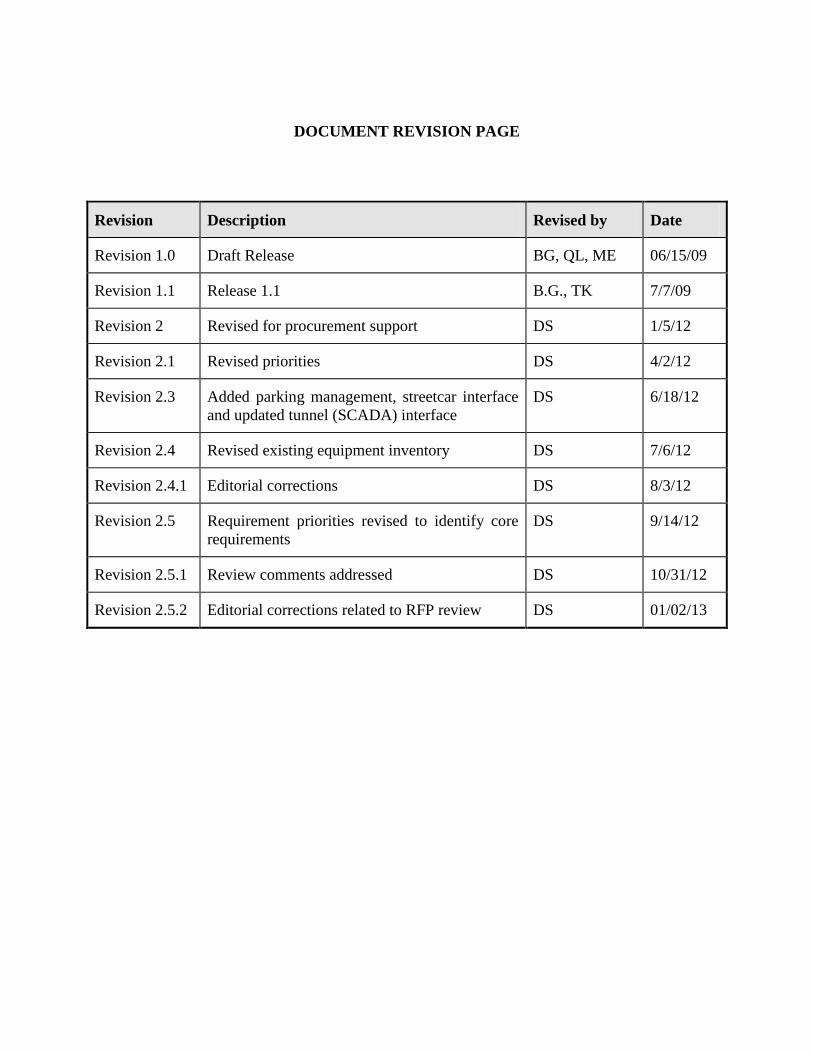
DOCUMENT REVISION PAGE
Revision Description Revised by Date
Revision 1.0 Draft Release BG, QL, ME 06/15/09
Revision 1.1 Release 1.1 B.G., TK 7/7/09
Revision 2 Revised for procurement support DS 1/5/12
Revision 2.1 Revised priorities DS 4/2/12
Revision 2.3 Added parking management, streetcar interface
and updated tunnel (SCADA) interface
DS 6/18/12
Revision 2.4 Revised existing equipment inventory DS 7/6/12
Revision 2.4.1 Editorial corrections DS 8/3/12
Revision 2.5 Requirement priorities revised to identify core
requirements
DS 9/14/12
Revision 2.5.1 Review comments addressed DS 10/31/12
Revision 2.5.2 Editorial corrections related to RFP review DS 01/02/13

Technical Report Documentation Page 1. Report No.
DDOT-TOA-CAPTOP-2008-004
2. Report Date
October 24, 2012
3. Title and Subtitle
CapTOP Phase 1: Software Functional Requirements Development Task 4: Functional Requirements Document
4. Contract or Grant No.
Original POKA-2006-T-0055-VH Revision DCKA-2010-T-0043
5. Author(s)
Original Barry Grasso, Qiang Li, Manzur Elahi Revision Dwight Shank 6. Performing Organization Name and Address
Original Daniel Consultants, Inc. 8950 Route 108 East, Suite 229 Columbia, Maryland 21045 Revision Iteris, Inc. 107 Carpenter Drive, Suite 230 Sterling, VA 20164
7. Type of Report and Period Covered.
Original Task 3 Report November 2008 – July 2009 Revision Task 2.1 Report Rev 4 August 2011 – September 2012
8. Sponsoring Agency Name and Address District of Columbia District Department of Transportation 55 M Street, SE, Suite 400 Washington, DC 20003
9. Supplementary Notes None
10. Abstract
The objective of this report is to document the Functional Requirements for the CapTOP program. This document includes a structured list of prioritized functional requirements organized by functional area. The revision updates the document to reflect evolution in system requirements and correct errata.
11. Key Words
CapTOP, Functional Requirements, ATMS, District of Columbia, ITS
12. Distribution Statement
No restrictions. This document is available through DDOT.
13. Security Classif.(of this report)
Unclassified 14. Security Classif.(of this page)
Unclassified 15. No. of Pages
300 16. Price
N/A

Task 4 Functional Requirements Document
CapTOP Phase 1: Software Functional Requirements Development
i
TABLE OF CONTENTS
Section Page No.
1. Introduction ................................................................................................................................1 1.1 Purpose ...............................................................................................................................1
1.2 Scope ..................................................................................................................................2 1.3 Organization of Functional Requirements .........................................................................3 1.4 System Overview ...............................................................................................................4 1.4.1 Facilities ................................................................................................................................ 5 1.4.2 Hardware and Equipment ...................................................................................................... 5 1.4.3 Software .............................................................................................................................. 13 1.4.4 Personnel ............................................................................................................................. 17 1.4.5 Operational Procedures ....................................................................................................... 18 1.4.6 Additional Support Necessary to Operate the Deployed System ........................................ 19
1.5 Definitions ........................................................................................................................19
1.6 Test Methods ....................................................................................................................22 1.6.1 Demo ................................................................................................................................... 22 1.6.2 Test ...................................................................................................................................... 22 1.6.3 Analyze ............................................................................................................................... 22 1.6.4 Inspect ................................................................................................................................. 22
1.7 Requirements Traceability ...............................................................................................23 1.8 Document Organization ...................................................................................................23
2. Referenced Documents ............................................................................................................24
3. Functional Requirements .........................................................................................................26
3.1 General Requirements ......................................................................................................26 3.1.1 System-Level Requirements ............................................................................................... 26
3.1.1.1 CapTOP Architectural Requirements ............................................................................. 26 3.1.1.2 CapTOP Standards Compliance ...................................................................................... 28 3.1.1.3 System Level Functional Requirements.......................................................................... 28
3.2 Database Requirements ....................................................................................................33 3.2.1 Database Architecture Requirements .................................................................................. 33 3.2.2 GIS Database Requirements ............................................................................................... 36 3.2.3 Log Database Requirements ............................................................................................... 37 3.2.4 Configuration Database Requirements ............................................................................... 40 3.2.5 Operations Database Requirements .................................................................................... 41 3.2.6 Archive Database Requirements ......................................................................................... 43 3.2.7 Database Report Requirements ........................................................................................... 45 3.2.8 Database Security Requirements......................................................................................... 49 3.2.9 Database Backup and Failure Requirements ....................................................................... 53 3.2.10 Archiving, Warehousing, Mining Requirements ................................................................ 54
3.3 Graphic User Interface Requirements ..............................................................................55 3.3.1 General GUI Requirements ................................................................................................. 55 3.3.2 CapTOP Toolbar Requirements .......................................................................................... 58 3.3.3 Map Display Requirements ................................................................................................. 61 3.3.4 CapTOP Web Interface Requirements ................................................................................ 68 3.3.5 GUI Subsystem Requirements ............................................................................................ 69

Task 4 Functional Requirements Document
CapTOP Phase 1: Software Functional Requirements Development
ii
3.3.6 GUI Administrative Requirements ..................................................................................... 71 3.4 Process Requirements .......................................................................................................77 3.4.1 Process Initialization and Termination................................................................................ 77 3.4.2 Process Status and Monitoring ............................................................................................ 77
3.5 Configuration Requirements ............................................................................................77 3.5.1 Parameter Selection and Table Updates .............................................................................. 77 3.5.2 Configuration Management Software ................................................................................. 77
3.6 Support Function Requirements .......................................................................................77 3.6.1 Event Handling, Including Error Logging, Visual/Audible Alarms ................................... 77 3.6.2 Communication Text Messaging / Alerts ........................................................................... 78 3.6.3 Task and Event Scheduler ................................................................................................... 78 3.6.4 System Backups .................................................................................................................. 78 3.6.5 Performance Requirements ................................................................................................. 78 3.6.6 System Failover................................................................................................................... 79 3.6.7 Backup TMC ....................................................................................................................... 79 3.6.8 On-Line Help ...................................................................................................................... 79 3.6.9 On-Line Documentation ..................................................................................................... 79 3.6.10 Traffic Data Analysis and Visualization ............................................................................. 79 3.6.11 Performance Measurement Requirements .......................................................................... 80 3.6.12 System Administration Functions ....................................................................................... 80
3.7 Subsystem Functional Requirements ...............................................................................81 3.7.1 Traffic Surveillance Requirements ..................................................................................... 81
3.7.1.1 CCTV Requirements ....................................................................................................... 81 3.7.1.1.1 Accessing the CCTV System .................................................................................... 81 3.7.1.1.2 Monitoring Camera Status ........................................................................................ 84 3.7.1.1.3 CCTV Control Commands ........................................................................................ 88 3.7.1.1.4 CCTV Tours .............................................................................................................. 89 3.7.1.1.5 CCTV Tour Schedule ................................................................................................ 90 3.7.1.1.6 CCTV Presets ............................................................................................................ 91 3.7.1.1.7 CCTV Video Routing ............................................................................................... 92 3.7.1.1.8 CCTV Reports........................................................................................................... 93 3.7.1.1.9 CCTV Application Interfaces ................................................................................... 95 3.7.1.1.10 CCTV Video Recording .......................................................................................... 95 3.7.1.1.11 CCTV Logging Requirements ................................................................................ 97 3.7.1.1.12 CCTV Archiving Requirements .............................................................................. 98
3.7.1.2 Traffic Detection Stations ............................................................................................... 99 3.7.1.2.1 Accessing the Traffic Detection Station Subsystem ................................................. 99 3.7.1.2.2 Monitoring Traffic Detection Station Status ........................................................... 103 3.7.1.2.3 Traffic Detection Station Reports ........................................................................... 106 3.7.1.2.4 Traffic Detection Station Logging Requirements ................................................... 109 3.7.1.2.5 Traffic Detection Station Archiving Requirements ................................................ 111
3.7.1.3 Permanent Count Stations ............................................................................................. 111 3.7.1.3.1 Accessing the Permanent Count Station Subsystem ............................................... 111 3.7.1.3.2 Monitoring Permanent Count Station Status ........................................................... 115 3.7.1.3.3 Permanent Count Station Reports ........................................................................... 118 3.7.1.3.4 Permanent Count Station Logging Requirements ................................................... 121 3.7.1.3.5 Permanent Count Station Archiving Requirements ................................................ 122
3.7.1.4 Congestion Alerts .......................................................................................................... 123 3.7.1.5 Traffic.Com Interface .................................................................................................... 124
3.7.1.5.1 Accessing the Traffic.Com Interface Subsystem .................................................... 124

Task 4 Functional Requirements Document
CapTOP Phase 1: Software Functional Requirements Development
iii
3.7.1.5.2 Monitoring Traffic.Com Station Status ................................................................... 127 3.7.1.5.3 Traffic.Com Station Reports ................................................................................... 129 3.7.1.5.4 Traffic.Com Station Logging Requirements ........................................................... 132 3.7.1.5.5 Traffic.Com Station Archiving Requirements ........................................................ 134
3.7.1.6 SpeedInfo Interface ....................................................................................................... 134 3.7.1.6.1 Accessing the SpeedInfo Interface Subsystem ....................................................... 134 3.7.1.6.2 Monitoring SpeedInfo Station Status ...................................................................... 137 3.7.1.6.3 SpeedInfo Station Reports ...................................................................................... 140 3.7.1.6.4 SpeedInfo Station Logging Requirements .............................................................. 142 3.7.1.6.5 SpeedInfo Station Archiving Requirements ............................................................ 144
3.7.1.7 CIPS Interface ............................................................................................................... 144 3.7.1.8 ROP AVL Tracking Interface ....................................................................................... 145
3.7.2 Traffic Control and Traveler Information Requirements .................................................. 145 3.7.2.1 DMS and PDMS Requirements .................................................................................... 145
3.7.2.1.1 Accessing the DMS/PDMS System ........................................................................ 145 3.7.2.1.2 Monitoring DMS/PDMS Status .............................................................................. 149 3.7.2.1.3 DMS/PDMS Control Commands ............................................................................ 153 3.7.2.1.4 DMS/PDMS Message Scheduler ............................................................................ 155 3.7.2.1.5 DMS/PDMS Reports ............................................................................................... 156 3.7.2.1.6 DMS/PDMS Message Editor .................................................................................. 158 3.7.2.1.7 Font Editor .............................................................................................................. 162 3.7.2.1.8 Graphics Editor ....................................................................................................... 162 3.7.2.1.9 DMS/PDMS Logging Requirements ...................................................................... 163 3.7.2.1.10 DMS/PDMS Archiving Requirements .................................................................. 165
3.7.2.2 HAR Requirements ...................................................................................................... 165 3.7.2.2.1 Accessing the HAR System .................................................................................... 165 3.7.2.2.2 Monitoring HAR Status .......................................................................................... 169 3.7.2.2.3 HAR Control Commands ........................................................................................ 171 3.7.2.2.4 HAR Message Scheduler ........................................................................................ 173 3.7.2.2.5 Reports .................................................................................................................... 174 3.7.2.2.6 HAR Message Editor .............................................................................................. 175 3.7.2.2.7 HAR Logging Requirements................................................................................... 178 3.7.2.2.8 HAR Archiving Requirements ................................................................................ 180
3.7.2.3 Traffic Signal Interface Requirements .......................................................................... 180 3.7.2.3.1 Accessing the Traffic Signal System Interface ....................................................... 180 3.7.2.3.2 Monitoring Traffic Signal Status ............................................................................ 184 3.7.2.3.3 Traffic Signal Reports ............................................................................................. 190 3.7.2.3.4 Traffic Signal Logging Requirements ..................................................................... 191 3.7.2.3.5 Traffic Signal Archiving Requirements .................................................................. 192
3.7.3 Incident Management Requirements (including Special Event Management) ................. 193 3.7.3.1 Accessing the Incident Management System ................................................................ 193 3.7.3.2 Monitoring Incident Status ............................................................................................ 207 3.7.3.3 Incident Detection and Classification ........................................................................... 209 3.7.3.4 Managing Incident Response ........................................................................................ 212 3.7.3.5 Incident Management Scheduler ................................................................................... 218 3.7.3.6 Incident Management Reports ...................................................................................... 219 3.7.3.7 Incident Management Logging Requirements .............................................................. 224 3.7.3.8 Incident Management Archiving Requirements ........................................................... 226 3.7.3.9 Incident Management ROP, MPD, and Snow Center Support Requirements .............. 227 3.7.3.10 Response Plan Editor ................................................................................................ 229

Task 4 Functional Requirements Document
CapTOP Phase 1: Software Functional Requirements Development
iv
3.7.4 Emergency Management/Evacuation Requirements ........................................................ 231 3.7.5 Traveler Information Requirements .................................................................................. 232
3.7.5.1 Travel Time ................................................................................................................... 232 3.7.5.2 Web-Based Traveler’s Information............................................................................... 232 3.7.5.3 Congestion and Traffic Condition Monitoring ............................................................. 233 3.7.5.4 Special Event Management ........................................................................................... 233 3.7.5.5 Incident Management .................................................................................................... 233 3.7.5.6 Dissemination Partners ................................................................................................. 234
3.8 Interfaces to Other Systems/Applications within DDOT ...............................................234 3.8.1 CVISN/WIM Interface Requirements............................................................................... 234 3.8.2 Tunnel Operations Center Interface Requirements ........................................................... 238 3.8.3 Streetcar System Interface Requirements ......................................................................... 238 3.8.4 CityWorks Interface Requirements ................................................................................... 239 3.8.5 Asset Management Requirements ..................................................................................... 239
3.8.5.1 Inventory Management ................................................................................................. 242 3.8.5.2 Repair and Maintenance ................................................................................................ 242
3.8.6 Interface to Signal Maintenance Contractor’s Work Order Database ............................... 242 3.8.7 StormTrak Interface Requirements ................................................................................... 243 3.8.8 RWIS Interface Requirements .......................................................................................... 244
3.8.8.1 Accessing the Roadway Weather Information System (RWIS) Interface .................... 244 3.8.8.2 Monitoring RWIS Status ............................................................................................... 247 3.8.8.3 RWIS Traveler Information .......................................................................................... 260 3.8.8.4 RWIS Reports ............................................................................................................... 261 3.8.8.5 RWIS Logging Requirements ....................................................................................... 263 3.8.8.6 RWIS Archiving Requirements .................................................................................... 264
3.8.9 Regional Weather Interface Requirements ....................................................................... 265 3.8.10 Video Switcher and Video Wall Integration ..................................................................... 265 3.8.11 Integration with Future IP Video Data .............................................................................. 266 3.8.12 DDOT Web Interface ........................................................................................................ 266 3.8.13 UCC Interface ................................................................................................................... 266 3.8.14 DPW Interface................................................................................................................... 266 3.8.15 WMATA Interface ............................................................................................................ 267 3.8.16 MPD and Capitol Police Interface .................................................................................... 267 3.8.17 Fire/Rescue Interface ........................................................................................................ 268 3.8.18 Homeland Security/EMA (HSEMA) Interface ................................................................. 268 3.8.19 Video Aircraft Downlink Interface ................................................................................... 269 3.8.20 Parking Management Interface ......................................................................................... 269
3.9 Regional C2C Requirements ..........................................................................................270 3.9.1 Real-Time Video/Data Sharing ......................................................................................... 270 3.9.2 Agency Interfaces ............................................................................................................. 272
3.9.2.1 RITIS Interface ............................................................................................................. 272 3.9.2.2 511 Interface ................................................................................................................. 273 3.9.2.3 INRIX Interface ............................................................................................................ 273 3.9.2.4 CAPWIN Interface ........................................................................................................ 273 3.9.2.5 CHART Interface .......................................................................................................... 274 3.9.2.6 RICCS Interface ............................................................................................................ 274 3.9.2.7 VDOT NOVA Interface ................................................................................................ 274
3.10 Legacy Interface Requirement .......................................................................................274 3.11 Security Requirements ...................................................................................................274 3.11.1 Workstation and Server Security ...................................................................................... 274

Task 4 Functional Requirements Document
CapTOP Phase 1: Software Functional Requirements Development
v
3.11.2 Users and Groups Privileges ............................................................................................. 275 3.11.3 DDOT Web Security ......................................................................................................... 275
3.12 Hardware Requirements .................................................................................................275 3.13 General Warranty ...........................................................................................................275 3.14 Correction of Defects .....................................................................................................276 3.15 Failure to Maintain Entire Project ..................................................................................276
3.16 Software Licenses ...........................................................................................................277 3.17 Software Warranty .........................................................................................................280 3.18 Qualification Test Requirements for Final Product Acceptance ....................................281 3.19 Training ..........................................................................................................................281
4. National ITS Architecture Consistency .................................................................................284
4.1 Introduction ....................................................................................................................284 4.2 Conformity Assessment .................................................................................................285

Task 4 Functional Requirements Document
CapTOP Phase 1: Software Functional Requirements Development
vi
LIST OF FIGURES
Figure Page No.
FIGURE 1 Context Diagram for CapTOP System ........................................................................ 8 FIGURE 2 CapTOP Hardware Architecture ............................................................................... 11
FIGURE 3 CapTOP Software Architecture ................................................................................. 14 FIGURE 4 Federal Rule-Making for Architecture Consistency................................................ 284

Task 4 Functional Requirements Document
CapTOP Phase 1: Software Functional Requirements Development
vii
LIST OF TABLES
Table Page No.
TABLE 1 Functional Areas 3 TABLE 2 CapTOP ITS Devices 12
TABLE 3 Operations Personnel Staffing 17 TABLE 4 Maintenance Personnel Staffing 18 TABLE 5 Roadway Operations Patrol Personnel Staffing 18 TABLE 6 Database Summary Error! Bookmark not defined. TABLE 7 Archive Requirements Summary Error! Bookmark not defined.
TABLE 8 Default Database Access Rights Error! Bookmark not defined. TABLE 9 Extended Status Data Definitions for RWIS Stations Error! Bookmark not defined. TABLE 10 Traceability of CapTOP System to National ITS Architecture 286
TABLE 11 Mapping of CapTOP Central System's Supplemental Functionalities to ITS National
Architecture 290

Task 4 Functional Requirements Document
CapTOP Phase 1: Software Functional Requirements Development
viii
ACRONYMS
Abbreviation Full Text
AADT Annual Average Daily Traffic
ANSI American National Standards Institute
API Application Program Interface
ASCII American Standard Code for Information Interchange
ATC Advanced Traffic Controller
ATMIS Advanced Traffic Management & Information System
ATMS Advanced Traffic Management System
AVI Automatic Vehicle Identification
AVL Automatic Vehicle Location
C2C Center-to-Center
C2F Center-to-Field
CAD Computer-Aided Dispatch
CapTOP Capital Traffic Operation Platform
CapWIN Capital Wireless Integrated System
CASE Computer-Aided Software Engineering
CATT Center for Advanced Transportation Technology
CCTV Closed-Circuit Television
CHART Coordinated Highway Action Response Team
CIP Critical Infrastructure Protection
CIPS Critical Infrastructure Protection System
CVISN Commercial Vehicle Information Systems and Networks
CO Carbon Monoxide
ConOps Concept of Operations
COTS Commercial-Off-The-Shelf
CSV Comma Separated Value
DBMS Database Management System
DDOT District Department of Transportation
DMS Dynamic Message Sign
DOT Department of Transportation
DPW Department of Public Works
DVR Digital Video Recorder
EMA Emergency Management Agency (now HSEMA)
ESRI Environmental Systems Research Institute
FCC Federal Communications Commission

Task 4 Functional Requirements Document
CapTOP Phase 1: Software Functional Requirements Development
ix
FHWA Federal Highway Administration
FRD Functional Requirements Document
GIS Geographic Information System
GPS Global Positioning System
GUI Graphical User Interface
H/W Hardware
HAR Highway Advisory Radio
HSEMA Homeland Security and Emergency Management Agency
IM Incident Management
IPMA Infrastructure Project Management Administration
ITE Institute of Transportation Engineers
ITS Intelligent Transportation System
LAN Local Area Network
LOS Level Of Service
MD Maryland
MDOT Maryland Department of Transportation
MOE Measures of Effectiveness
MPD Metropolitan Police Department
MPEG Moving Picture Experts Group
MPH Mile Per Hour
MTBF Mean Time Between Failures
MTTR Mean Time To Repair
MWCOG Metropolitan Washington Council of Governments
NAS Networked Archive Storage
NAWAS National Warning System
NCR National Capital Region
NOAA National Oceanic and Atmospheric Administration
NOVA Northern Virginia
NTCIP National Transportation Communications for ITS Protocol
NTSC National Television System Committee
NVR Network Video Recorder
NWS National Weather Service
ORD Operational Requirements Document
OITI Office of Information Technology and Innovation
PC Personal Computer
PDA Personal Data Assistant
PDMS Portable Dynamic Message Sign

Task 4 Functional Requirements Document
CapTOP Phase 1: Software Functional Requirements Development
x
POC Point of Contact
RAID Redundant Array of Independent Disks
RDBMS Relational Database Management System
RICCS Regional Incident Communications and Coordination System
RITIS Regional Integrated Transportation Information System
ROC Roadside Operations Computers
ROP Roadway Operations Patrol
RPM Rotations Per Minute
RTM Requirements Traceability Matrix
RTMS Roadway Traffic Monitoring System
RWIS Roadway Weather Information System
S/W Software
SCADA Supervisory Control and Data Acquisition
SDE Spatial Database Engine
SHA State Highway Administration
SOP Standard Operating Procedure
SQL Structured Query Language
TCP/IP Transmission Control Protocol/Internet Protocol
TCP/UDP Transmission Control Protocol/User Datagram Protocol
TIMS Traffic Information Management System
TMC Traffic Management Center
TMDD Traffic Management Data Dictionary
TSO Transportation System Operator
UCC Unified Communications Center
UMD University of Maryland
USCP United States Capitol Police
VA Virginia
VCR Video Cassette Recorder
VDOT Virginia Department of Transportation
VIPS Video Interoperability for Public Safety
VPN Virtual Private Network
VGA Video Graphics Array
WAN Wide Area Network
WASA Water and Sewage Authority
WIM Weigh-in-Motion
WMATA Washington Metropolitan Area Transit Authority
XML Extensible Markup Language
Task 4 Functional Requirements Document
CapTOP Phase 1: Software Functional Requirements Development
xi
XVGA Extended Video Graphics Array
Task 4 Functional Requirements Document
CapTOP Phase 1: Software Functional Requirements Development
1
1. INTRODUCTION
The District Department of Transportation (DDOT) Traffic Management Center (TMC) plays a
critical role in managing the traffic and mitigating the adverse impacts of incidents and special
events on the District’s transportation system. The new CapTOP system is the core of the
Advanced Traffic Management System (ATMS). As envisioned by DDOT, CapTOP will evolve
into a system to provide centralized management of traffic management activities, including
management and operation of ITS devices, and traffic management for planned and unplanned
incidents and events that impact transportation in the District. CapTOP will facilitate the
exchange of transportation-related information across a variety of agencies within the region, and
provide an integrated interface to a number of traffic-management related systems. DDOT
commissioned the development of operational and functional requirements documents to form
the basis for the detailed design and implementation of the CapTOP.
Under a previous contract, an inventory and analysis of existing DDOT ITS systems and
software were performed, stakeholder interviews were conducted, operational objectives and
user needs were identified, a Concept of Operations was developed, an Operational
Requirements Document was developed, and a Functional Requirements Document was
developed. The current work revises the previous versions of the Functional Requirements
Document to prepare the functional requirements as found in this document for support of a
successful system procurement, to correct technical and editorial errors in the previous versions,
and to reflect ongoing evolution in ITS industry practices. The functional requirements describe
the capabilities and functions to be performed in the CapTOP system. The development of TMC
functional requirements documented in this report involved the analysis of what the system
needs to perform. The functional requirements support and are consistent with findings
produced by the prior contract and documented in Technical Memorandum 1: Document Review
Findings (ref
3), Technical Memorandum 2: Interview Findings and Stakeholders’ Needs
(ref 0
), the
Task 2 Report: Concept of Operations (ref
0), and the Task 3 Report: Operational Requirements
(ref
0).
The functional requirements are categorized and structured in a tabular, hierarchical
format in this document. A coding scheme is used to organize the requirements around
functional areas. A Computer-Aided Software Engineering (CASE) tool was used to ensure
traceability among functional requirements, operational requirements, user needs, and scenarios
(i.e., use cases). The database of requirements in the CASE tool has been updated in concert
with the revisions to this document.
1.1 Purpose
This Functional Requirements Document (FRD) is used in conjunction with the Concept of
Operations (ConOps) document and the Operational Requirements Document (ORD) to provide
a thorough understanding of the CapTOP system and to reduce the development effort by
minimizing errors, omissions, misunderstandings, and inconsistencies. It will be revised
periodically to reflect the expanding capabilities of the CapTOP system.

Task 4 Functional Requirements Document
CapTOP Phase 1: Software Functional Requirements Development
2
The purpose of the CapTOP system is to achieve the goals set forth in the CapTOP
Concept of Operations document, which supports the DDOT mission of providing safe and
efficient movement of people and goods in and around the District and providing a safe seamless
transportation system.
As stated in the Concept of Operations document, the goals of CapTOP are:
To assist in the timely response to incidents, special events, weather events, and
emergencies, and to disseminate traffic information to the roadway users in real time
so that they can make informed decisions;
To reduce recurring traffic congestion, and resultant delay, emissions, and fuel
consumption;
To reduce traffic congestion caused by incidents.
These goals drive the following operational objectives for the CapTOP system:
Provide an integrated operational framework to support all operational functions to
enable reliable, accurate, and timely traffic management and traveler information;
Provide a modular and flexible system architecture that can easily integrate with
existing and new systems;
Provide the capability for an integrated, dynamic, real-time, and proactive traffic
management system to mitigate congestion and optimize traffic operations;
Provide the capability to integrate traffic management across the entire District of
Columbia and to provide tools to coordinate with neighboring jurisdictions;
Support detection and rapid response to incidents and collaborative action to provide
integrated responses;
Provide information and functional capabilities to accommodate transportation
management strategies;
Accommodate the operational needs of all operational areas;
Provide information management and communication capabilities to ensure the
integrated operation of all ITS/ATMS elements;
Support management functions to measure and maintain optimal system performance;
Support management functions to measure and maintain TMC operators’ operational
performance.
These objectives were the basis for the operational requirements that guided development
of the functional requirements described in this document.
1.2 Scope
The development of TMC functional requirements documented in this report involved the
analysis of what, when and how well the system needs to perform. The functional requirements
in this document were derived mainly from the following four (4) documents:

Task 4 Functional Requirements Document
CapTOP Phase 1: Software Functional Requirements Development
3
Technical Memorandum 1: Document Review Findings(ref
3);
Technical Memorandum 2: Interview Findings and Stakeholders Needs(ref
0);
Task 2 Report: Concept of Operations(ref
0);
Task 3 Report: Operational Requirements(ref
0).
A complete list of documents referenced is provided in Section 2.
This FRD covers the analysis of what CapTOP needs to perform and defines the
functional requirements that CapTOP needs to implement in order to satisfy the concept of
operations and the operational requirements.
1.3 Organization of Functional Requirements
The functional requirements are organized into categories grouping similar requirements together.
To maintain a common structure and facilitate traceability, the functional requirements are
presented in a tabular format with the following columns:
ID – A unique identifier for each requirement. The identifier is an alpha-numeric
pattern in the form of AAA-BBB.C.D.E.F where:
o AAA = a 3-character identifier to indicate the type of functional requirement
(e.g., DMS); (See Table 1 for a complete list.)
o BBB.C.D.E.F = a numeric identifier to uniquely identify the requirement
within a functional area (e.g., 100.1.1); Fields C, D, E, and F are optional and
are used to structure hierarchical requirements.
ORD Req ID – A unique identifier that allows the source/originator of the
requirement to be traced. The “ORD Req ID” identifier traces back to an operational
requirement identified in Task 3 Report: Operational Requirements(ref
0).
Description – A concise description of the functional requirement.
Priority –A 1-digit number representing the relative priority of the requirement or a
“C”, where “C” represents a Core function of the system that must be present in all
operational versions, 1 = high, 2 = medium, and 3 = low. Note: the priorities of the
functional requirements have been refined from what was documented in the ORD
and Release 1 of this document.
Test Method – One of demo, test, analyze or inspect. Refer to section 1.6 Test
Methods for additional information.
TABLE 1 below provides a list of the type of functional requirements used in this
document.
TABLE 1 Functional Areas Functional Areas Code
Archive Database ADB

Task 4 Functional Requirements Document
CapTOP Phase 1: Software Functional Requirements Development
4
Functional Areas Code
Congestion Alerts CGA
Closed-Circuit Television CCT
Critical Infrastructure Protection System CIP
Configuration Database CDB
Configuration Management System CMS
CVISN CVN
Database Architecture DBA
Database Backup and Failure DBF
Database Reports DBR
Database Security DBS
Database Warehouse and Archiving DWA
Department of Public Works Interface DPW
Dynamic Message Signs or Portable Dynamic Message Signs DMS
Emergency Management/Evacuation EME
GIS Database GDB
Graphical User Interface GUI
Hardware HWR
Highway Advisory Radio HAR
Homeland Security and Emergency Management HSE
Incident Management INM
Logging Requirements LOG
Map Display GUI
Metropolitan Police Department MPD
Operations Database ODB
Parking Management Interface PAM
Performance Requirements PER
Permanent Count Stations PCS
Regional Traffic Coordination RTC
Regional Weather Interface REW
Roadway Weather Information System Interface RWI
SCADA Interface SCA
Special Event Management INM
SpeedInfo Interface SPD
StormTrak STI
Streetcar Interface STC
System Level Requirements SYS
System Maintenance Contractor’s Work Order Maintenance Database SMC
Traffic.com Interface TDC
Traffic Data Analysis TDA
Traffic Detection Stations TDC
Traffic Signals SIG
Video Aircraft Downlink Requirements VAD
Asset Management Interface ASM
1.4 System Overview
This section provides an overview of the envisioned CapTOP system.
This section includes information about the system’s environment in terms of the
following categories:
Facilities

Task 4 Functional Requirements Document
CapTOP Phase 1: Software Functional Requirements Development
5
Hardware and Equipment
Software
Personnel
Operational Procedures
Support Necessary to Operate the Deployed System
FIGURE 1 illustrates the CapTOP system context diagram. This diagram identifies the
interfaces between CapTOP and various systems, centers, and devices.
1.4.1 Facilities
The DDOT Traffic Management Center (TMC) is a 24x7x365 traffic management facility.
Primary server and communication equipment along with operational equipment is located on
the 2nd
floor of the Reeves Center, which is located at 2000 14th
Street, NW, in Washington, DC.
Operational equipment for the TMC is located on the 2nd
floor of the UCC to leverage the
infrastructure capabilities of that facility. Refer to Section 3.1 of the Task 2 Report: Concept of
Operations (ref
0) for additional information. The TMC serves as the management and control
center in the District, and provides monitoring and control over all DDOT’s ITS assets. The
Transportation System Operators (TSOs), whom operate the system, are located in the UCC,
while the maintenance, Roadway Operations Patrols (ROPs), and support personnel are located
at the Reeves Center. The Reeves location also houses the spare ITS field devices.
While many offices of DDOT staff are located at 55 M Street, SE, no permanent facilities are
planned for installation there. Access to CapTOP capabilities will be provided using office
automation computers and DDOT staff laptops across DC network connections. Access
provided by the public Internet will also be available at this location.
The TMC supports regional emergency management functions and information sharing
and integration with MDOT, VDOT and Washington Metropolitan Area Transit Authority
(WMATA). The TMC serves as a command and control center to integrate new functions
identified in the area of homeland security, including Critical Infrastructure Protection (CIP),
interoperable communications, intelligence/information sharing, information gathering, and
information dissemination.
CapTOP is supported by an operations and development environment as follows:
1. Operations Environment – this environment houses the production system, which is the
“live” system to manage day-to-day traffic operations.
2. Development Environment – this environment is used for software development, testing,
simulation and training where items such as patched software, new releases, and new
control strategies are tested in an offline configuration.
1.4.2 Hardware and Equipment
This section is subdivided into field hardware and center hardware. The CapTOP program
interfaces with a variety of ITS field devices and/or servers, including CCTV, vehicle detectors,

Task 4 Functional Requirements Document
CapTOP Phase 1: Software Functional Requirements Development
6
RWIS, DMS, HAR, and a traffic signal system. A description of each of these devices is
provided in Section 3.1 of the Task 2 Report: Concept of Operations (ref
0).

Task 4 Functional Requirements Document
CapTOP Phase 1: Software Functional Requirements Development
7
Portable Dynamic Message Signs
(116)
CIPS
170E Signal System (~1600 )
Public Safety Police, Fire, EMS, Homeland Security
NCR Emergency Response
CHART SOC, Mont. Cty, MSP, PG Cty, AOC, TOCs
Stationary Dynamic Message Signs (13)
Service Request & Task Order System
(CityWorks)
DC Unified Communications
Center (UCC)
Web Services traveler info
info reques t
weather status request status, weather data
signal maint. outage report (work orders) signal maint. status
QuicNet signal status, video
video detection commands
incident detection alarms
sign cmds sign status
CCTV control cmds video data
sign cmds Perform CAPTOP
Functions incident notification &
coord, shared video/data
TE Operations Specialists
incident notification & coord
incident notification & coord,
shared video/data
operator’s cmds analysis displays
VDOT NRO/STC
Alerting Sytems • Public Emergency Notification System
• WASA • NAWAS
incident notification & coord
emergency alerts
Highway Advisory Radio (6)
HAR cmds
HAR status
Color Key: Implemented in CAPTOP I Enhancements Planned in CAPTOP II Enhancements Planned in CAPTOP III
Video Downlinks from Aircraft
streaming video - aerial
TMC Operators
Parking Management
speed, vol/count/occ/class data
RWIS (6)
sign status
RITIS
incident notification &
coor dinati on, shar ed video/data
Future Interfaces Existing Interfaces
511
info reques t
traveler info
Roadway Operations Patrol
video snapshot, AVL data service request
WMATA
incident notification & coord
Snow Operations
Vehicle Detectors • 122 VDS • 30 PCS
• 50 SpeedInfo DVSS - 100s • 15 Traffic.com RTMS
parking data traffic data
AVL data road weather status
service request
incident notification & coord,
shared video/data
Close Circuit Television (135)
operator’s cmds system displays
INRIX travel time data
CVISN incident notification & coord
CVISN truck data & alerts, video
ATC Signal System (Future)
ATC signal status
incident notification & coord
transit
data
Streetcar Operations
traffic data
transit data

Task 4 Functional Requirements Document
CapTOP Phase 1: Software Functional Requirements Development
8
FIGURE 1 Context Diagram for CapTOP System

Task 4 Functional Requirements Document
CapTOP Phase 1: Software Functional Requirements Development
9
With regard to the central hardware, refer to FIGURE 2 for a diagram illustrating the
CapTOP central hardware configuration. For the CapTOP implementation, the following
hardware is anticipated:
Client Workstations – one for each operator in each shift. The CapTOP user
interface is graphical and GIS-based; therefore, 4-headed monitors are envisioned
with leading edge dual Intel-based processors.
Network Switch – a 10/100/1000Base-T Ethernet switch is required for network
connectivity and the display of live IP video. The CapTOP software executes in a
distributed computing environment utilizing the Transmission Control
Protocol/Internet Protocol (TCP/IP) to communicate between software applications.
Video Switcher – a 512 input x 256 output analog NTSC video switcher is required
for legacy video.
Application Servers – the number of these servers varies based on the number of
subsystems deployed, the processing power of the server, and how many ITS devices
each of those subsystems is required to support.
Database Servers – these servers host relational database management software with
built-in redundancy for high availability.
Communication Servers – these servers are used to provide center-to-center and
center-to-field communications using T-1 connections, dialup modems, firewalls,
terminal servers, and wireless modems. TCP/IP and serial protocols are used to
communicate with all devices. Where available, standard protocols, such as NTCIP,
will be utilized.
As previously discussed, the hardware and software discussed in this section is available
in the operational environment, and a replica copy (though on a smaller scale) in the
development (or support) environment.
In addition to the field and center hardware identified above, the CapTOP architecture
supports the addition of future ITS field devices and center hardware.

Task 4 Functional Requirements Document
CapTOP Phase 1: Software Functional Requirements Development
10
…
Client Workstations
Network Switch
CapTOP Application Servers (Primary/Backup for CCTV,
HAR, DMS, Video Server,
Traffic Data Server, etc.)
Database Servers (Primary/Backup) Web Server
(Primary/Backup)
Communication Devices (Modems, Firewalls, T-1 circuits,
Terminal Servers, etc.)
Video Wall
512x256 Video
Switcher
DVR/NVR
CapTOP Communication
Servers (Primary/Backup)
Archived
Storage
CapTOP Server
FEP Communication
Servers (Primary/Backup
for Signals/CCTV)
Traffic Signal Servers
(Primary/Backup for 170E
and ATC Controllers.)
Note: The Traffic Signal Servers and FEP Communications Servers are part of the existing Signal System. CapTOP
will interface to these systems. They are shown here for completeness. They are not considered part of CapTOP.

Task 4 Functional Requirements Document
CapTOP Phase 1: Software Functional Requirements Development
11
FIGURE 2 CapTOP Hardware Architecture

Task 4 Functional Requirements Document
CapTOP Phase 1: Software Functional Requirements Development
12
TABLE 2 provides a listing the various types of devices that are under the purview of the
CapTOP system.
TABLE 2 CapTOP ITS Devices
Device Type Existing
Quantity
Under
Central
Control
Network Manufacturer Model # Protocol Used
CCTV 150 Yes Twisted Pair Honeywell KD6
Proprietary
Phillips/Bosch
170E Traffic
Signals ~1700 Yes Twisted Pair McCain 170E
Proprietary
QuickCom (McCain)
ATC Traffic
Signals TBD TBD TBD TBD TBD NTCIP
HAR 6 Yes Cellular HIS (Quixote)
DR1500AM
Recorder/Player
AM Transmitter
Module: Model
DRTXM2
BlackMax for Radio
Transmitter
Proprietary Quixote
DR1500
RWIS 6 Some
Twisted Pair
and Spread
Spectrum SSI (Quixote) SSRI 900 Freeware
Proprietary SSI, Use
SCAN Server Data
Export Software API
Portable DMS 43 Yes CDMA/EVDO
VER-MAC
(Centralo is
central software)
3048SCEN2008,
3056SCEN2007 NTCIP
Portable DMS
for Speed
Monitoring 6 No
None - No
centralization
potential at all TrafficLogix SJT-02
Bluetooth for local
communication with
a laptop.
Fixed DMS
2 Existing
11 Planned No None
Existing Mark IV,
Planned TBD
Existing FP9000-NL,
Planned TBD
Existing Proprietary,
Planned NTCIP
SpeedInfo
Speed Detectors 46 No None
Doppler
(SpeedInfo) DVSS-100
Interface is to
SpeedInfo's Server
via Traffic Data
Server
RTMS SVO
Detectors 15 No None
RTMS
(Traffic.com) RTMS
Interface is to
Traffic.com's Server
via Traffic Data
Server
Video Switcher
512 Inputs/
256 Outputs Yes Coax Bosch Allegiant
Proprietary
Phillips/Bosch
Video Wall 1 Yes Coax Clarity
Lion Wn-6720-sx,
Lion Wn-4030-S
Proprietary Crestron
Video Wall
Controller
Permanent
Count Stations 30 Planned Yes
Twisted Pair
and Spread
Spectrum
(Various):
Loops (20)
w/piezos, Video
(1-Traficon),
RTMS (5-EIS),
IR (1-Tirtl),
Acoustic (1 -
SmarTek)
ATRs;
5 different servers
Interface is to
Proprietary Protocols
(Roadtrax, Traficon,
EIS, Tirtl, SmarTek)
via Traffic Data
Server

Task 4 Functional Requirements Document
CapTOP Phase 1: Software Functional Requirements Development
13
Device Type Existing
Quantity
Under
Central
Control
Network Manufacturer Model # Protocol Used
Traffic
Detection
Stations 122 Planned Yes
Twisted Pair
and Wireless
TBD - Contract is
not yet awarded
In-Pavement
Wireless Sensor
Interface is to
Proprietary Protocol
via Traffic Data
Server
Weigh-In-
Motion (WIM)
Stations 3 Yes
Count,
classification,
and weight
International
Road Dynamics Single Load Cell
Proprietary via XML
using C2C.
1.4.3 Software
The CapTOP software consists of a large number of processes (software applications) that
interact in a cooperative environment, as subsystems, to provide CapTOP functionality.
FIGURE 3 provides an illustration of the envisioned CapTOP software architecture.
Each CapTOP subsystem is described below:
Operator Interface Subsystem – this subsystem provides an intuitive graphical user
interface (GUI). An integral part of the GUI is the Geographical Information System
(GIS) – based map display, which provides spatial and temporal functions linking
traffic management activities to real-world maps.
DMS Subsystem – this subsystem provides monitor and control functions for the
DMS/PDMS devices.
CCTV/Video Subsystem – this subsystem provides monitor and control functions
for the CCTV cameras, as well as the video switcher and video wall.
HAR Subsystem – this subsystem provides monitor and control functions for the
HAR devices.
Vehicle Detection Subsystem – this subsystem provides monitor and control
functions for the various types of vehicle detectors, including loops, piezos, radar-
based devices, etc. Some detectors are sponsored by 3rd
parties and are read-only
(i.e., no control). This subsystem is based off 3rd
party COTS products.
Signal Subsystem – this subsystem provides monitor and control functions for the
170E traffic control signals via QuicNet™ and also ATC controllers via the future
ATC software. This subsystem is based off 3rd
party COTS products. The interface
between CapTOP and QuicNet, and between CapTOP and the ATC software is

Task 4 Functional Requirements Document
CapTOP Phase 1: Software Functional Requirements Development
14
FIGURE 3 CapTOP Software Architecture
Signal
Subsystem
RWIS
Subsystem
Operator
Interface
Subsystem
DMS
Subsystem
CCTV/Video
Subsystem
Vehicle
Detector
Subsystem
External
Interface
Subsystem
Data Exchange
Subsystem
WWW/Video
Server
Subsystem
Database
Management
Subsystem
Incident
Management
Subsystem
HAR
Subsystem
Communications Manager
LAN
Internet
Users
CAPTOP Subsystems
Roadside SubsystemsVehicle Subsystems
Traveler Subsystems
Wire-Line Communications (Twisted Pair, T1, Frame Relay, Coax, Ethernet, Serial)Wide-Area/Wireless Communications (800 MHz,
1900 MHz, EV-DO, HSDPA, Edge, Cellular)
CCTV SignalsRWIS
ISPs
Portable
DMSHAR
Road Maint.
Equipment
Snow Removal
Equipment
Aircraft Video
DownlinkFixed DMS
HAR
CIPS
AVL
Subsystem
Vehicle
Detection
Stations
Roadway Operation
Patrols
Data
Processing
Subsystem
GIS Subsystem
Color Key: Existing Subsystems
Future Subsystems
Management
Subsystems(Configuration Mgmt,
Asset Mgmt, Work Order Mgmt)
Infrastructure Services Subsystem• Event Scheduler • Software Monitor
• Event Display • Archived Storage
• Alerts/Notifications • NTP Server• Account Management • Traffic Data Server
Permanent
Count
Stations
Speed Info
Stations
Traffic.com
Stations

Task 4 Functional Requirements Document
CapTOP Phase 1: Software Functional Requirements Development
15
limited to monitoring functions only. All signal control functions are handled from
within the QuicNet and the ATC software packages.
Infrastructure Services Subsystem – this subsystem provides services that are
available to the operator and multiple subsystems, including the following:
o Event Scheduler – this service schedules recurring and non-recurring events
to remind the operator to take action. This can include scheduled
DMS/PDMS messages (e.g., display a new message, or blank sign), HAR
messages, alerts, or CCTV tours to be run.
o Event Display – this service provides the ability to display all system,
application, and operator events and alerts to the operator.
o Alert System – this service provides alerts in the form of emails, text
messages or paging messages to individual subscribers or distribution lists.
o Account Management – this service provides the ability to manage (add,
delete, change) user accounts, passwords, and groups.
o Software Monitor – this service provides the ability to monitor, stop, and
restart critical software processes.
o Archived Storage – this service provides the necessary storage infrastructure
(e.g., RAID, NAS, jukebox, etc.) to support the data archive.
o NTP Server – this service provides Network Time Protocol (NTP), time
synchronization data to all workstations, servers, and controllers.
o Traffic Data Server – this service provides the server software to integrate
data from vehicle detection stations, permanent count stations, Traffic.com
stations, SpeedInfo stations, INRIX, and WIM stations. This accomplished
using a collection of processes that collects the data and stores the data in
CapTOP’s operations database.
Incident Management Subsystem – this subsystem provides robust incident
management functions, including special event management. Support is provided for
automated response plans, as well as on-line procedures.
GIS Subsystem – this subsystem provides the map based capability that works in
conjunction with the GUI. This subsystem is based off 3rd
party COTS products.
RWIS Subsystem – this subsystem provides monitor-only functions for the RWIS
devices, which are managed by a 3rd
party.
WWW/Video Server Subsystem – this subsystem provides data that will be
disseminated on the Internet, including live traffic video (or snapshots), congestion,
incident, special event, and construction information. This subsystem also facilitates
video sharing between other agencies and centers.
Management Subsystems – this subsystem supports three separate applications:
o Asset Management – this application provides the ability to manage mobile
and fixed assets. The software centrally manages the inventory of assets, their

Task 4 Functional Requirements Document
CapTOP Phase 1: Software Functional Requirements Development
16
location, the users of them, configuration and warranty information, and all
costs associated with the various assets. This subsystem is based off 3rd
party
COTS products.
o Work Order Management – this application provides the ability to enter,
schedule, and track work orders. This subsystem also provides the ability to
enter and track customer complaints, such as signal outages. This subsystem
is based off 3rd
party COTS products.
o Configuration Management – this application provides an integrated source
code baseline for all aspects of the project. This subsystem provides version
control, with version numbers, and descriptions to identify what is changed
for each release.
Data Exchange Subsystem – this subsystem provide interfaces to the other systems
(e.g., CIPS, RITIS, INRIX, etc.) for the purpose of transmitting and receiving traffic
and incident data. One of the supported interfaces is a standard interface for the
purpose of exchanging two-way incident and video information with other centers
(i.e., center-to-center), agencies, or private sector companies. CapTOP will provide a
mechanism for exchanging two (2) types of data:
o Traffic data – this type of data is pushed to other centers and includes traffic
condition data (e.g., speed, volume, and occupancy), incident information
(e.g., accidents, construction, and lane closure), special event information,
video, and current device status (e.g., DMS/PDMS messages, HAR messages,
etc.);
o Command/Control data – this type of data is when an operator in one center
issues a command to another center to change the current state of an ITS
device (e.g., an operator can send a request to change a DMS/PDMS that
another center operates).
Database Management Subsystem – this subsystem provides relational database
management functions, including redundancy and mechanisms to provide high
availability. This subsystem is based off 3rd
party COTS products.
Data Processing Subsystem – this subsystem is responsible for providing the
following services:
o Data Collection and Analysis – a collection of applications that provide
access to historical traffic, incident, and performance data. Also provides
tools that support graphical displays, statistical analysis, and data mining.
o Data Warehousing and Archiving – provides a repository for electronically
stored data. Includes software and hardware that support electronic storage
and retrieval of traffic data, response plans, timing plans, ITS device status,
system event log, measures of effectiveness and other data. A collection of
applications to support various reporting and analysis functions, and to
provide a means to retrieve and analyze data, to extract, transform, load, and
display data.

Task 4 Functional Requirements Document
CapTOP Phase 1: Software Functional Requirements Development
17
External Interface Subsystem – this subsystem provide custom interfaces to
external systems not addressed by the data exchange subsystem (e.g., StormTrak,
CVISN, NCR, etc.).
Automatic Vehicle Location (AVL) Subsystem – this subsystem provides
automated tracking of AVL-equipped vehicles, such as ROPS and maintenance
vehicles. This subsystem is based off 3rd
party COTS products.
1.4.4 Personnel
This section describes the different types of personnel necessary to operate the CapTOP system.
The following personnel are necessary to staff CapTOP:
Operations Personnel – are responsible for traffic management functions and are
knowledgeable and experienced in the various aspects of ITS including, monitoring,
incident management, traffic control, dispatch, and traffic information dissemination.
The staff consists of a TMC Manager and TMC operators. Staffing requirements are
based on the size of the system, the number of ITS devices, the average daily number
of incidents, and the need to conduct 24x7x365 operations. Refer to TABLE 3 for the
hours of operation and staffing levels based on DDOT’s existing system.
TABLE 3 Operations Personnel Staffing
Day of Week Shift Hours # Supervisors
(Leads)
# Operators
Weekdays
Morning 5:30 AM – 3:30 PM 1 4
Mid 2:30 PM – Midnight 1 3
Night 10:30 PM – 8:00 AM 1 4
Weekends
Morning 5:30 AM – 3:30 PM 1 1
Mid 2:30 PM – Midnight 1 1
Night 10:30 PM – 8:00 AM 1 1
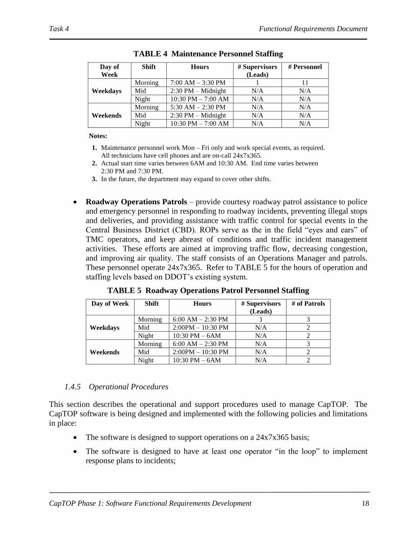
Maintenance Personnel – are responsible for corrective and preventive maintenance
of all ITS assets. The maintenance staff consists of one (1) supervisory engineering
technician (supervisor), seven (7) engineering technicians, one (1) IT technician, one
(1) electrical engineering technician, and two (2) electronics mechanics. Staffing
requirements are based on the size of the system, the number of ITS devices, and the
average daily number of devices to service. Refer to TABLE 4 for the hours of
operation and staffing levels based on DDOT’s existing system.
Task 4 Functional Requirements Document
CapTOP Phase 1: Software Functional Requirements Development
18
TABLE 4 Maintenance Personnel Staffing
Day of
Week
Shift Hours # Supervisors
(Leads)
# Personnel
Weekdays
Morning 7:00 AM – 3:30 PM 1 11
Mid 2:30 PM – Midnight N/A N/A
Night 10:30 PM – 7:00 AM N/A N/A
Weekends
Morning 5:30 AM – 2:30 PM N/A N/A
Mid 2:30 PM – Midnight N/A N/A
Night 10:30 PM – 7:00 AM N/A N/A
Notes:
1. Maintenance personnel work Mon – Fri only and work special events, as required.
All technicians have cell phones and are on-call 24x7x365.
2. Actual start time varies between 6AM and 10:30 AM. End time varies between
2:30 PM and 7:30 PM.
3. In the future, the department may expand to cover other shifts.
Roadway Operations Patrols – provide courtesy roadway patrol assistance to police
and emergency personnel in responding to roadway incidents, preventing illegal stops
and deliveries, and providing assistance with traffic control for special events in the
Central Business District (CBD). ROPs serve as the in the field “eyes and ears” of
TMC operators, and keep abreast of conditions and traffic incident management
activities. These efforts are aimed at improving traffic flow, decreasing congestion,
and improving air quality. The staff consists of an Operations Manager and patrols.
These personnel operate 24x7x365. Refer to TABLE 5 for the hours of operation and
staffing levels based on DDOT’s existing system.
TABLE 5 Roadway Operations Patrol Personnel Staffing
Day of Week Shift Hours # Supervisors
(Leads)
# of Patrols
Weekdays
Morning 6:00 AM – 2:30 PM 1 3
Mid 2:00PM – 10:30 PM N/A 2
Night 10:30 PM – 6AM N/A 2
Weekends
Morning 6:00 AM – 2:30 PM N/A 3
Mid 2:00PM – 10:30 PM N/A 2
Night 10:30 PM – 6AM N/A 2
1.4.5 Operational Procedures
This section describes the operational and support procedures used to manage CapTOP. The
CapTOP software is being designed and implemented with the following policies and limitations
in place:
The software is designed to support operations on a 24x7x365 basis;
The software is designed to have at least one operator “in the loop” to implement
response plans to incidents;
Task 4 Functional Requirements Document
CapTOP Phase 1: Software Functional Requirements Development
19
All operations activities will be guided by the use of written standard operating
procedures for all traffic management activities. This material will be available on-
line within CapTOP;
The software is designed to operate on commercially available operating systems and
hardware platforms.
1.4.6 Additional Support Necessary to Operate the Deployed System
This section includes all other supporting labor that is not specifically designated by the operations of the
system. This support includes the following personnel:
ITS Management Staff – consists of individuals who are responsible for managing
the current and future TMC operations, and maintenance activities.
ITS Integration and Development Staff – consist of individuals who are
responsible for managing all integration and development activities for the TMC.
This includes integrating and developing new software to address operations needs.
1.5 Definitions
The following terms are used throughout this document:
1. Archive – a collection of historical records stored in a separate location.
2. Archiving – the process of removing selected data records from active databases and
storing them in an archive database. The archive database makes historical information
that is normally purged from the system, available for longer time periods.
3. Backup Database – a copy (e.g., .bck file) of portions of the master database stored on
backup media, and typically transaction log-based.
4. Business Database – a logical copy of the master database.
5. CIP Systems – Critical Infrastructure Protection Systems (CIPS) is comprised of
intelligent video systems (also known as “Smart Cameras”) which use video analytics
technology to detect stopped vehicles, pedestrians, packages, etc. in areas near critical
infrastructure.
6. Data Mining – data processing using sophisticated data search capabilities and statistical
algorithms to discover patterns and correlations in data. Also involves the process of
sorting through large amounts of data and picking out relevant information.
7. External Agencies – these are any agencies, outside of DDOT, including other agencies
within the District of Columbia and surrounding areas, including the following:
a. Maryland State Highway Administration (MD SHA);
Task 4 Functional Requirements Document
CapTOP Phase 1: Software Functional Requirements Development
20
b. Virginia Department of Transportation (VDOT);
c. Maryland Department of Transportation (MDOT);
d. Montgomery County Department of Public Works & Transportation;
e. Prince George’s County Department of Public Works & Transportation;
f. DC Unified Command Center (UCC);
g. DC Public Safety;
h. National Capital Region (NCR) Emergency Response;
i. Metropolitan Washington Council of Governments (MWCOG);
j. University of Maryland (UMD) Center for Advanced Transportation Technology
(CATT);
k. DC Department of Public Works (DC DPW);
l. DC Water and Sewer Authority (DC WASA);
m. National Warning System (NAWAS);
n. Washington Metropolitan Area Transit Authority (WMATA);
o. DC Homeland Security and Emergency Management Agency (HSEMA);
p. DC Metropolitan Police Department (DC MPD);
q. United States Capitol Police (USCP).
8. Geocoding – the process of finding associated geographic coordinates (often expressed
as latitude and longitude) from other geographic data, such as street addresses, zip codes,
landmarks, hyperfills, buildings, areas, etc. With geographic coordinates the features can
be mapped and entered into a GIS, or the coordinates can be embedded into media such
as digital photographs via geotagging.
Reverse Geocoding is the opposite: finding an associated textual location such as a street
address, from geographic coordinates.
A geocoder is a piece of software or a (web) service that helps in this process.1
9. Incident – for this document, the definition of an incident is defined to be consistent with
the Traffic Incident Management Handbook which defines an incident as "any non-
recurring event that causes a reduction of roadway capacity or an abnormal increase in
demand." Under this definition, events such as traffic crashes, disabled vehicles, spilled
cargo, highway maintenance and reconstruction projects, and special events (e.g., ball
games, concerts, or any other event that significantly affects roadway operations) are
classified as an incident.
10. Incident Classification – for this document, the term incident classification is used to
identify a process used internally by the incident management subsystem to classify
incidents based on their location, incident type, incident subtype, and severity. The
classification results in an internal code that is not something useful for the operator, but
1 Taken from Wikipedia contributors, "Geocoding," Wikipedia, The Free Encyclopedia, accessed February 2009

Task 4 Functional Requirements Document
CapTOP Phase 1: Software Functional Requirements Development
21
is used by the incident management subsystem to lookup the most appropriate response
plan.
11. Intelligent Transportation Systems (ITS) Devices – for this document, “ITS Devices”
include devices such as, closed-circuit television (CCTV) cameras, Dynamic Message
Signs (DMS), Portable Dynamic Message Signs (PDMS), Highway Advisory Radios
(HAR), Roadway Weather Information Systems (RWIS), traffic detection stations,
permanent count stations, and traffic signals.
12. Intelligent Video Systems – these are video-based systems that use image processing,
video analytics, and other technologies to detect abnormal or suspicious behaviors, such
as stopped vehicles, loitering pedestrians, unattended packages, etc.
13. Master Database – the primary database used to store CapTOP data.
14. Mirrored Database – a copy of the master database stored on a backup server.
15. Permanent Count Station – a DDOT-owned traffic monitoring station that collects
traffic speed, volume, occupancy, and classification data.
16. SCADA – Supervisory Control and Data Acquisition (SCADA) are systems and
applications that collect data from sensors and machines in remote locations and send
them to a central computer for management and control. An example SCADA is
DDOT’s tunnel ventilation and control system.
17. Traffic Detection Station – unless noted otherwise, a DDOT-owned traffic monitoring
station that collects traffic speed, volume, and occupancy data.
18. User – a generic term used to denote the users of the CapTOP system. A user is assigned
by the System Administrator to one or more of the following groups, each with varying
privilege levels:
a. External User;
b. Maintenance Manager;
c. Maintenance Technician;
d. ROP Driver;
e. ROP Manager;
f. System Administrator;
g. TMC Manager;
h. TMC Operator;
i. Transportation Planner;
j. Traffic Engineer.
Task 4 Functional Requirements Document
CapTOP Phase 1: Software Functional Requirements Development
22
1.6 Test Methods
This section defines the set of qualification methods that will ensure that the requirements
specified in this document are met. Demo, test, analyze, and inspect are the four (4) methods that
will be used to verify the system requirements. These methods are defined below.
1.6.1 Demo
Demo (short for demonstration) is a variation of the “test” method that is used to verify
conformance of functional characteristics to specified requirements by pass/fail criteria without
the use of elaborate measurement equipment. Demonstration executes the functions of the
system, hardware configuration item(s), and/or computer software configuration item(s) using
data in a controlled situation. Observations of the predicted outputs or results demonstrate
verification of requirements. Simulated or live data may be used.
1.6.2 Test
To test requires exercising portions of the system hardware and/or software in a controlled
manner, to collect the data necessary to evaluate conformance to the specified requirements.
Real or simulated input is used to exercise specific segments of the system and to generate
predicted outputs. Data are formally recorded in accordance with procedures. Detailed analysis
is performed to determine requirements compliance, including comparison of Contractor test
results with results generated by Government-owned test equipment/software. Analysis as
described here is an integral part of the test method, separate and distinct from the analysis
method.
1.6.3 Analyze
To analyze requires the processing of accumulated data, including compilation of data obtained
from other methods. Techniques involve interpretation or interpolation/extrapolation of
analytical, simulated, or empirical data under defined conditions, or reasoning to show
compliance with requirements. Verification by computerized simulations is included in this
method.
1.6.4 Inspect
To inspect requires the visual examination of an item and the comparison of pertinent
characteristics with a predetermined qualitative and quantitative standard. Inspection is used to
verify compliance with specified requirements by examining engineering documentation and
products. For example, inspection is generally nondestructive and consists of visual or auditory
observations, gauging, or simple measurements without the use of precision measurement
equipment. The engineering documentation and products include, but are not limited to,
software and hardware flow diagrams, software code, engineering drawings, engineering plans,
and design specifications.

Task 4 Functional Requirements Document
CapTOP Phase 1: Software Functional Requirements Development
23
1.7 Requirements Traceability
As part of the FRD development effort, a Computer-Aided Software Engineering (CASE) tool
was used to ensure there was comprehensive mapping of all requirements, between the FRD and
the ORD, and also between the ORD and the user needs. This mapping and the associated
system engineering ensured all user needs were captured in the ORD and that all ORD
requirements were captured in the FRD. This product, known as a Requirements Traceability
Matrix (RTM), is a CASE tool report and is available for review by written request to the ITS
System Integration & Development Department within DDOT.
1.8 Document Organization
The document is organized as follows:
Chapter 1 introduces the document, provides a document purpose, provides a system
overview , and defines the purpose and scope of the functional requirements;
Chapter 2 provides a list of referenced documents;
Chapter 3 provides the functional requirements grouped by functional area;
Chapter 4 provides a National ITS Architecture mapping for consistency.

Task 4 Functional Requirements Document
CapTOP Phase 1: Software Functional Requirements Development
24
2. REFERENCED DOCUMENTS
The following documents have been used as reference material in the preparation of this report:
3. CapTOP Phase 1: Software Functional Requirements Development Technical
Memorandum 1: Document Review Findings, District Department of Transportation and
Daniel Consultants, Inc., August 1, 2008.
CapTOP Phase 1: Software Functional Requirements Development Technical Memorandum
2: Interview Findings and Stakeholders' Needs, District Department of Transportation
and Daniel Consultants, Inc., August 1, 2008.
CapTOP Phase 1: Software Functional Requirements Development Task 2: Concept of
Operations, District Department of Transportation and Daniel Consultants, Inc., October
10, 2008.
CapTOP Phase 1: Software Functional Requirements Development Task 3: Operational
Requirements, District Department of Transportation and Daniel Consultants, Inc., March
18, 2009.
ITS Mission Definition, Architecture Development Team, Research and Innovation
Technology Administration (RITA), US Department of Transportation, May, 2007.
Capital Traffic Operation Platform-State of Work, Transportation Operations Division,
Traffic Services Administration, District Department of Transportation, August 21, 2006.
DDOT ITS Program Review (PowerPoint Presentation), Transportation Operations Division,
District Department of Transportation, October 27, 2007.
Capital Traffic Operation Platform User Manual, Transportation Operation Division of
Traffic Services Administration, DDOT, November 2006.
Initiative Plan: New Transportation Management Center at Anacostia Gateway, DDOT,
January 27, 2006.
Standard Operating Procedures for Transportation Management Center (TMC), Operators
Manual Version 4, Prepared for District of Columbia Division of Transportation,
February 6, 2004, by DMJM&HARRIS.
District Response Plan Functional Annexes ESF #1, April 4, 2002
Technical Memorandum Draft “Operator Tasks and Workstation Requirements (Concept of
Operations)", Prepared for District of Columbia Division of Transportation, November
20, 2002, by Philip J. Tarnoff and Dunn Engineering Associates, Document No: 96028-
660-1004.
Concept of Operations SunGuide-ConOps-1.0.0, Southwest Research Institute, January 3,
2005.
Concept of Operations-Fontana/Ontario Advanced Traffic Management Information System
(ATMIS), Release 3.0, ITERIS Inc., December 3, 2000.

Task 4 Functional Requirements Document
CapTOP Phase 1: Software Functional Requirements Development
25
ATMS Concept of Operations, Version 0.7, VDOT, Northern Operations Region ATMS,
Attachment D of RFP #173-BLW, January 2007.
ATMS Software Requirement Specifications Version 0.4, VDOT Northern Operations
Region ATMS RFP # 173-BLW Attachment E, Trevilon Corporation, January 3, 2007.
Developing Functional Requirements for ITS Projects, Paul J. Gonzalez, Thomas B. Fowler,
Mitretek Systems, Inc., April, 2002.
CHART II System Requirements, M361-RS-002R2, Computer Sciences Corporation and PB
Farradyne Inc., May 2, 2000.
CHART Lite 3.0 System Design Document, Maryland State Highway Administration,
September 2005.
Regional Integration Transportation Information System (RITIS), Center for Advanced
Transportation Technology (CATT) Laboratory, All Hazards Forum, October 2006.
Metropolitan Washington Area ITS Architecture Interconnect Matrix, July 17, 2007.

Task 4 Functional Requirements Document
CapTOP Phase 1: Software Functional Requirements Development
26
3. FUNCTIONAL REQUIREMENTS
This section describes the functional requirements for the CapTOP system.
3.1 General Requirements
This section is divided into the following subsections:
System-Level Requirements;
Qualification Test Requirements for final Product Acceptance
Training Requirements
3.1.1 System-Level Requirements
3.1.1.1 CapTOP Architectural Requirements
FRD Req ID ORD Req ID Description Priority Test
Method
SYS-10 SR-SYS-1
CapTOP shall provide an open architecture with a
modular design that supports the following features
without the need for a major redesign:
a. integration of legacy systems;
b. scalability;
c. extensibility;
d. the addition of hardware, software and
communication technologies as they become
available;
e. incorporation of new modules;
f. incorporation of off-the-shelf
software/hardware components;
g. incorporation of new ITS devices;
h. database expansion.
C Inspect
SYS-20 SR-SYS-2
CapTOP shall provide a client-server based
architecture with the following features:
a. uniform and unified user interfaces;
b. a database management system;
c. communications and application servers that
allow the system to expand.
C Demo
SYS-30 SR-SYS-3 The CapTOP system shall be configurable to
accommodate system/module updates and expansions. C Inspect
SYS-40 SR-SYS-6
CapTOP shall provide the ability to support variations
in system configurations, and operations through
database and configuration file settings.
C Demo

Task 4 Functional Requirements Document
CapTOP Phase 1: Software Functional Requirements Development
27
FRD Req ID ORD Req ID Description Priority Test
Method
SYS-40.1 SR-SYS-26
CapTOP shall provide a configuration function to
allow authorized users to modify the following system
configuration data:
a. user permissions;
b. equipment/device settings for all ITS device
types;
c. communication settings.
Refer to the section Error! Reference source not
found. Error! Reference source not found. for
additional information.
C Demo
SYS-50 SR-SYS-4
CapTOP shall provide a low-coupling architecture and
minimize inter-dependencies between the systems
components.
1 Inspect
SYS-60 SR-SYS-5 The CapTOP system architecture shall be both web-
based and client-server based. C Demo
SYS-70 SR-SYS-16
CapTOP shall provide a platform to support
information sharing among DDOT personnel and
external organizations.
1 Inspect
SYS-80
SR-SYS-28,
UR-TO-13,
OR-TID-7,
OR-CMM-5,
OR-CIP-1,
OR-RTC-1
CapTOP shall provide an interface with the following
systems to support regional transportation management
by communicating and sharing information using
standards-based center-to-center protocols (NTCIP and
XML):
a. CHART;
b. NOVA OpenTMS;
c. MWCOG;
d. RITIS;
e. DDOT CIPS;
f. DDOT Snow Operations;
g. DC UCC;
h. DC Public Safety;
i. NCR Emergency Response;
j. WASA;
k. NAWAS;
l. WMATA;
m. DPW;
n. DC Streetcar Operations;
o. DC Tunnel Operations;
p. DC Parking Operations.
a. 2
b. 2
c. 3
d. 1
e. 1
f. 1
g. 1
h. 1
i. 1
j. 3
k. 3
l. 1
m. 2
n. 2
o. 2
p. 3
Demo
SYS-80.1
SR-SYS-28,
UR-TO-13,
OR-TID-7,
OR-RTC-1
CapTOP shall provide the ability to share the
following information with the partners above:
a. incident data;
b. traffic condition data;
c. ITS device status;
d. live video;
e. roadway weather information;
f. travel time data;
g. current DMS messages;
h. current HAR messages;
i. regional weather information.
1 Demo

Task 4 Functional Requirements Document
CapTOP Phase 1: Software Functional Requirements Development
28
FRD Req ID ORD Req ID Description Priority Test
Method
SYS-90 IR-GUI-17
CapTOP shall be capable of communicating to devices
using the following communication media:
a. regular telephone lines;
b. wireless connections;
c. leased lines;
d. twisted pair;
e. network connections.
Refer to subsystem requirements for additional details.
C Demo
3.1.1.2 CapTOP Standards Compliance
FRD Req ID ORD Req ID Description Priority Test
Method
SYS-100 SR-SYS-7
CapTOP shall utilize the following standards-based
interfaces, data formats, databases, and protocols:
a. NTCIP for communications with field
devices/equipment and other TMCs;
b. TCP/UDP as the communications protocol for
the transport layer;
c. XML for defining interface definitions;
d. ANSI SQL for database definitions.
Refer to subsystem requirements for additional details.
C Demo
SYS-100.1 OR-C2C-3
CapTOP shall implement center-to-center
communication via the NTCIP 2306 (Application
Profile for XML Message Encoding and Transport in
ITS Center to Center Communications - NTCIP C2C
XML) standard to facilitate interagency
communications and data exchange with other TMCs.
1 Demo
SYS-110 SR-SYS-8
CapTOP shall utilize the latest published NTCIP
standards for all NTCIP compliant field devices unless
otherwise approved by DDOT.
Refer to subsystem requirements for additional details.
1 Demo
SYS-120 SR-SYS-7 CapTOP shall provide an architecture that is consistent
with the National ITS Architecture. 1 Inspect
3.1.1.3 System Level Functional Requirements
FRD Req ID ORD Req ID Description Priority Test
Method
SYS-130 SR-SYS-10
CapTOP applications shall be designed for an event-
driven approach to accommodate the following
functions:
a. event response planning;
b. event management;
c. event tracking;
d. event analysis;
C Demo

Task 4 Functional Requirements Document
CapTOP Phase 1: Software Functional Requirements Development
29
FRD Req ID ORD Req ID Description Priority Test
Method
e. event recording;
f. event visualization.
SYS-140 SR-SYS-11
CapTOP shall provide functions to support the
management of the following activities:
a. daily traffic;
b. traffic incidents;
c. special events;
d. weather related events;
e. work zone;
f. Police emergencies.
C Demo
SYS-150 SR-SYS-12
Access to all CapTOP functions/applications shall be
provided from any CapTOP workstation within the
DDOT network, subject to user privileges.
1 Demo
SYS-150.1 SR-SYS-13 CapTOP shall prohibit the use of dedicated
workstations for specific functions. 1 Demo
SYS-150.2 SR-SYS-23,
OR-C2F-3
CapTOP shall provide the TMC Operator with
operational functions to monitor and control the
following field devices for any CapTOP workstation:
a. 170E-based traffic signals (monitoring only
via QuicNet);
b. ATC-based traffic signals (monitoring only
via the future Traffic Signal System);
c. CCTV cameras;
d. DMSs;
e. PDMSs;
f. HARs;
g. RWISs (monitoring only);
h. traffic detection stations (monitoring only);
i. Traffic.com stations (monitoring only);
j. SpeedInfo stations (monitoring only);
k. WIM stations (monitoring only);
l. Permanent count stations (monitoring only).
Refer to subsystem requirements for additional details.
C, items b
and k
priority 2
Demo
SYS-150.3 SR-SYS-9
CapTOP shall provide a platform that provides
integrated access to the following software
applications:
a. QuicNet 170E-based Signal System;
b. CityWorks;
c. ATC-based Signal System;
d. A contractor work-order tracking system for
signal maintenance.
Item a C,
items b
and d
priority 1,
item c
priority 2
Demo

Task 4 Functional Requirements Document
CapTOP Phase 1: Software Functional Requirements Development
30
FRD Req ID ORD Req ID Description Priority Test
Method
SYS-170 SR-SYS-22,
OR-PM-2
CapTOP shall provide comprehensive reporting
capabilities for system performance, measurement and
evaluation in the following operational areas:
a. Traffic signal management;
b. CCTV management;
c. DMS management;
d. PDMS management;
e. HAR management;
f. Traffic detector management;
g. RWIS management;
h. Incident management;
i. Congestion monitoring;
j. Operator productivity;
k. Operator effectiveness;
l. CapTOP management.
Refer to subsystem requirements for additional details.
2 Demo
SYS-180 SR-SYS-36
CapTOP shall be able to generate real-time reports on
device equipment status for the following subsystems:
a. DMS;
b. PDMS;
c. CCTV;
d. HAR;
e. RWIS;
f. Traffic Detection Stations;
g. Traffic.com Stations;
h. SpeedInfo Stations;
i. WIM Stations;
j. Permanent Count Stations;
k. Signals.
Refer to subsystem requirements for additional details.
1, item i
priority 2 Demo
SYS-190 SR-SYS-24
CapTOP shall be able to facilitate the dissemination of
timely, accurate information through the following
devices and methods:
a. HAR;
b. DMS;
c. the Internet;
d. traveler information kiosks;
e. automated telephone based information
systems;
f. text messages;
g. instant messages;
h. e-mail messages.
Refer to subsystem requirements for additional details.
Items a
and b C,
items c, f,
g, and h
priority 1,
items d
and e
priority 2
Demo

Task 4 Functional Requirements Document
CapTOP Phase 1: Software Functional Requirements Development
31
FRD Req ID ORD Req ID Description Priority Test
Method
SYS-200 SR-SYS-25
CapTOP shall integrate a database management system
with functions for collection, integration, analysis,
archiving, and reporting for the following types of
data:
a. traffic and road condition data;
b. weather-related road conditions;
c. weather-related warnings and closures;
d. work zone data and restrictions;
e. incident data.
Refer to the Database section for additional
information.
1 Demo
SYS-210
SR-SYS-25,
OR-TDCA-19,
OR-MMC-3
The CapTOP system shall operate in the following
modes:
a. Startup Mode – This mode starts all systems
orderly and renders the TMC operable.
b. Normal Mode – This is the normal operational
mode of the system in which all services are
available. The TMC is staffed with a TMC
Manager and operators 24x7x365 in
accordance with the staffing plan. From this
mode, the system can transition to any of the
other modes below.
c. Maintenance Mode – This operational mode
will be used when system upgrades or repairs
are taking place. The system will be capable of
running from a single workstation/server in this
mode.
d. Development/Simulation/Training Mode –
This mode will be used periodically for
activities, such as testing a new software
release, simulating a new control
strategy/tactic, or the training of a new
operator. This mode typically executes on a
non-operational set of hardware.
e. Backup Mode – This operational mode will be
used in the event of a catastrophic failure at the
Primary TMC. In this scenario, backup
operations will occur at the backup TMC.
Refer to DBF-10* and SYS-260* for more
information.
f. Shutdown Mode – This mode shuts down all
systems orderly and renders the TMC
inoperable.
1 Demo
SYS-210.1 OR-MMC-3
CapTOP shall provide an online training mode to train
TMC Operators, Managers, Maintenance Technicians,
and other users that require CapTOP access.
3 Demo
SYS-210.2 OR-MMC-4 CapTOP shall provide a limited set of test devices, 1 or
more per subsystem, to use in training mode. 3 Demo
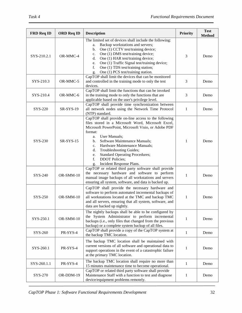
Task 4 Functional Requirements Document
CapTOP Phase 1: Software Functional Requirements Development
32
FRD Req ID ORD Req ID Description Priority Test
Method
SYS-210.2.1 OR-MMC-4
The limited set of devices shall include the following:
a. Backup workstations and servers;
b. One (1) CCTV test/training device;
c. One (1) DMS test/training device;
d. One (1) HAR test/training device;
e. One (1) Traffic Signal test/training device;
f. One (1) TDS test/training station;
g. One (1) PCS test/training station.
3 Demo
SYS-210.3 OR-MMC-5
CapTOP shall limit the devices that can be monitored
and controlled in the training mode to only the test
devices.
3 Demo
SYS-210.4 OR-MMC-6
CapTOP shall limit the functions that can be invoked
in the training mode to only the functions that are
applicable based on the user's privilege level.
3 Demo
SYS-220 SR-SYS-19
CapTOP shall provide time synchronization between
all network nodes using the Network Time Protocol
(NTP) standard.
1 Demo
SYS-230 SR-SYS-15
CapTOP shall provide on-line access to the following
files stored in a Microsoft Word, Microsoft Excel,
Microsoft PowerPoint, Microsoft Visio, or Adobe PDF
format:
a. User Manuals;
b. Software Maintenance Manuals;
c. Hardware Maintenance Manuals;
d. Troubleshooting Guides;
e. Standard Operating Procedures;
f. DDOT Policies;
g. Incident Response Plans.
1 Demo
SYS-240 OR-SMM-10
CapTOP or related third party software shall provide
the necessary hardware and software to perform
manual image backups of all workstations and servers
ensuring all system, software, and data is backed up.
1 Demo
SYS-250 OR-SMM-10
CapTOP shall provide the necessary hardware and
software to perform automated incremental backups of
all workstations located at the TMC and backup TMC
and all servers, ensuring that all system, software, and
data are backed up nightly.
1 Demo
SYS-250.1 OR-SMM-10
The nightly backups shall be able to be configured by
the System Administrator to perform incremental
backups (i.e., only files that changed from the previous
backup) or a complete system backup of all files.
1 Demo
SYS-260 PR-SYS-4 CapTOP shall provide a copy of the CapTOP system at
the backup TMC location. 1 Demo
SYS-260.1 PR-SYS-4
The backup TMC location shall be maintained with
current versions of all software and operational data to
support operations in the event of a catastrophic failure
at the primary TMC location.
1 Demo
SYS-260.1.1 PR-SYS-4 The backup TMC location shall require no more than
15 minutes maintenance time to become operational. 1 Demo
SYS-270 OR-DDM-19
CapTOP or related third party software shall provide
Maintenance Staff with a function to test and diagnose
device/equipment problems remotely.
1 Demo

Task 4 Functional Requirements Document
CapTOP Phase 1: Software Functional Requirements Development
33
FRD Req ID ORD Req ID Description Priority Test
Method
SYS-280 UR-TO-30
CapTOP or related third party software shall provide
System Administrator and Maintenance Manager
access to troubleshooting functions to diagnose
problems with the following:
a. ITS field devices;
b. CapTOP database;
c. workstation and server performance;
d. network performance.
1 Demo
3.2 Database Requirements
3.2.1 Database Architecture Requirements
FRD Req ID ORD Req ID Description Priority Test
Method
DBA-10
SR-SYS-1,
SR-SYS-2,
OR-DWA-1
CapTOP shall provide a client-server based Relational
Database Management System (RDBMS) with the
following architectural features:
a. SQL command line interface;
b. application program interface;
c. scalable in terms of number of users and
database size;
d. support for RAID 0-5;
e. support for symmetric multi-processing;
f. comprehensive reporting functions.
C Demo
DBA-10.1 SR-SYS-1,
SR-SYS-2
CapTOP shall utilize a COTS-based RDBMS to
support the following data management
implementations:
a. simple data marts that gather data from ITS
devices and equipment to serve TMC
manager/operators;
b. data warehouses that collect, integrate, and
summarize transportation data.
2 Demo
DBA-10.2
SR-SYS-1,
SR-SYS-2,
OR-DWA-2,
OR-DWA-2
The CapTOP RDBMS shall provide an ANSI standard
SQL database engine to support interoperability with
other third party applications.
C Demo
DBA-10.3
SR-SYS-1,
SR-SYS-2,
OR-DWA-2
The CapTOP RDBMS shall support multi-users and
simultaneous access. C Demo
DBA-10.3.1 SR-SYS-1,
SR-SYS-2
The CapTOP RDBMS shall support up to 30
simultaneous connections from a combination of
system applications and users without affecting its
performance.
1 Demo
DBA-10.4 SR-SYS-30
The CapTOP RDBMS shall support local or remote
access by applications or users. C Demo
DBA-10.5 OR-SMM-10,
OR-DWA-2
The CapTOP RDBMS shall provide backup and
recovery data management support. 1 Demo
DBA-10.6 OR-DWA-2 The CapTOP RDBMS shall have the ability to support
database diagnostics. 1 Demo
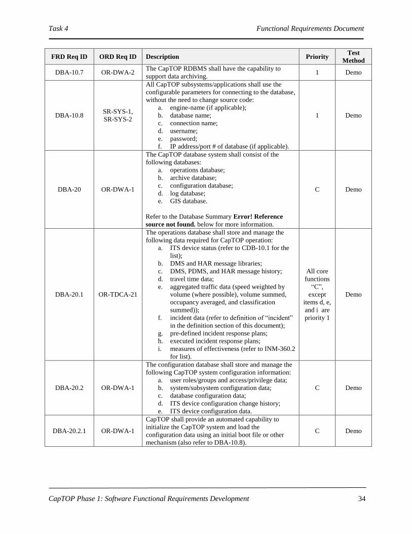
Task 4 Functional Requirements Document
CapTOP Phase 1: Software Functional Requirements Development
34
FRD Req ID ORD Req ID Description Priority Test
Method
DBA-10.7 OR-DWA-2 The CapTOP RDBMS shall have the capability to
support data archiving. 1 Demo
DBA-10.8 SR-SYS-1,
SR-SYS-2
All CapTOP subsystems/applications shall use the
configurable parameters for connecting to the database,
without the need to change source code:
a. engine-name (if applicable);
b. database name;
c. connection name;
d. username;
e. password;
f. IP address/port # of database (if applicable).
1 Demo
DBA-20 OR-DWA-1
The CapTOP database system shall consist of the
following databases:
a. operations database;
b. archive database;
c. configuration database;
d. log database;
e. GIS database.
Refer to the Database Summary Error! Reference
source not found. below for more information.
C Demo
DBA-20.1 OR-TDCA-21
The operations database shall store and manage the
following data required for CapTOP operation:
a. ITS device status (refer to CDB-10.1 for the
list);
b. DMS and HAR message libraries;
c. DMS, PDMS, and HAR message history;
d. travel time data;
e. aggregated traffic data (speed weighted by
volume (where possible), volume summed,
occupancy averaged, and classification
summed));
f. incident data (refer to definition of “incident”
in the definition section of this document);
g. pre-defined incident response plans;
h. executed incident response plans;
i. measures of effectiveness (refer to INM-360.2
for list).
All core
functions
“C”,
except
items d, e,
and i are
priority 1
Demo
DBA-20.2 OR-DWA-1
The configuration database shall store and manage the
following CapTOP system configuration information:
a. user roles/groups and access/privilege data;
b. system/subsystem configuration data;
c. database configuration data;
d. ITS device configuration change history;
e. ITS device configuration data.
C Demo
DBA-20.2.1 OR-DWA-1
CapTOP shall provide an automated capability to
initialize the CapTOP system and load the
configuration data using an initial boot file or other
mechanism (also refer to DBA-10.8).
C Demo

Task 4 Functional Requirements Document
CapTOP Phase 1: Software Functional Requirements Development
35
FRD Req ID ORD Req ID Description Priority Test
Method
DBA-20.3 OR-DWA-1,
OR-DDM-21
The log database shall store and manage the following
CapTOP logged data:
a. system events:
i. application startup;
ii. application shutdown;
iii. open database connection;
iv. close database connection;
v. user-invoked database transactions (query,
modifications);
b. system warnings, errors and alarms;
c. operator events.
C Demo
DBA-20.4 OR-DWA-13
The archive database shall store the data archived from
the following databases:
a. operations database;
b. configuration database;
c. log database.
C Demo
DBA-20.5 OR-DWA-1
The GIS database shall store and manage geo-
referenced data.
Refer to GUI-120.1.1 for additional information.
C Demo
A summary of the databases, including the data types, the source of data, and the real time
storage location are shown in Error! Reference source not found.below.
TABLE 6 Database Summary
Database Summary Table
# Data Types Source Real-Time Storage Location
1.
ITS Device Configuration Change
History CapTOP
CapTOP Configuration
Database
2. ITS Device Configuration Data CapTOP
3.
User Account, Roles/Groups, and
Access Privilege Data CapTOP
4.
System/Subsystem Configuration
Data CapTOP
5. GIS Configuration Change History CapTOP CapTOP GIS Database
6. GIS Data CapTOP
7. Operator Log CapTOP
CapTOP Log Database 8. System Alerts CapTOP
9. System Log CapTOP
10. Incident Data CapTOP
11. Incident Alerts CapTOP
CapTOP Operations Database
12. CCTV Status CapTOP
13. DMS/PDMS Message History CapTOP
14. DMS/PDMS Message Library CapTOP
15. DMS/PDMS Status CapTOP
16. Executed Incident Response Plans CapTOP
17. HAR Message History CapTOP
18. HAR Message Library CapTOP
19. HAR Status CapTOP
20. Measures of Effectiveness CapTOP
21. Pre-Defined Incident Response Plans CapTOP

Task 4 Functional Requirements Document
CapTOP Phase 1: Software Functional Requirements Development
36
Database Summary Table
# Data Types Source Real-Time Storage Location
22. Travel Time Data INRIX (INRIX Data Server)
CapTOP Operations Database
(Traffic Data Server)
23. Speed INRIX Sensors (INRIX Data Server)
24. SpeedInfo Station Status
SpeedInfo Sensors (SpeedInfo Data
Server)
25. Speed
SpeedInfo Sensors (SpeedInfo Data
Server)
26. Traffic Detection Station Status Traffic Detection Station Server
27. Speed, Volume, Occupancy Traffic Detection Station Server
28. Traffic.com Station Status
Traffic.com Sensors (Traffic.com Data
Server)
29. Speed, Volume, Occupancy
Traffic.com Sensors (Traffic.com Data
Server)
30. Permanent Count Station Status
Permanent Count Stations (PCS Data
Server)
31.
Speed, Volume, Occupancy,
Classification
Permanent Count Stations (PCS Data
Server)
32. WIM Status
CVISN (Roadside Operations
Computer) CapTOP Operations Database,
Roadside Operations
Computer 33. WIM Data
CVISN (Roadside Operations
Computer)
34. RWIS Status SCAN Web (SCAN Web Database) CapTOP Operations Database
and RWIS Server 35. RWIS Data SCAN Web (SCAN Web Database)
36. 170E Traffic Signal Status Data
QuicNet (QuicNet Signal System
Database)
CapTOP Operations Database
and QuicNet Signal System
Database
37. 170E Traffic Signal Plan Data QuicNet
QuicNet Signal System
Database Only
38. Video Recordings CapTOP DVR
39. ATC Traffic Signal Status Data ATC Signal System Database
CapTOP Operations Database
and ATC Signal System
Database (future)
40. ATC Traffic Signal Plan Data ATC Signal System Database
ATC Signal System Database
Only(future)
3.2.2 GIS Database Requirements
FRD Req ID ORD Req ID Description Priority Test
Method
GDB-10 OR-DWA-1
CapTOP shall utilize a COTS GIS package for the
storage and retrieval of CapTOP geo-referenced data
compatible with DDOT and District of Columbia
practices.
C Demo
GDB-20 OR-DWA-1,
OR-IM-5
CapTOP shall be capable of referencing location-
related alphanumeric data to spatial data via GIS
geocoding.
C Demo
GDB-30 IR-GUI-2
The GIS spatial data used in CapTOP shall conform to
DDOT's GIS standards to allow for seamless
information exchange with citywide spatial databases.
C Demo
GDB-30.1 IR-GUI-6,
OR-DWA-1
The GIS database shall allow users the ability to add,
edit, delete, import, and export geo-referenced map
data related to ITS-specific information, subject to
C Demo

Task 4 Functional Requirements Document
CapTOP Phase 1: Software Functional Requirements Development
37
FRD Req ID ORD Req ID Description Priority Test
Method
privilege level.
GDB-30.2 IR-GUI-6,
OR-DWA-1
CapTOP shall be able to import ARC/GIS formatted
shape files and display as a separate layer on the
CapTOP map display.
C Demo
GDB-40 OR-DWA-1
The GIS database shall store and maintain the link-
node street network layer to enable connectivity with
streets and intersections having relationships with each
other.
C Demo
GDB-40.1 OR-DWA-1 The GIS database shall support dynamic segmentation. C Demo
GDB-40.2 OR-DWA-1
The GIS database shall support milepost referencing
for freeways and street address referencing for
arterials.
C Demo
GDB-40.3 OR-DWA-1 The link-node network layer will include definition of
both links and nodes. C Demo
GDB-40.3.1 OR-DWA-1
Nodes will represent specific locations in citywide
spatial databases, be defined for each link endpoint,
and will include the following data at a minimum:
a. Node ID (required)
b. Node location in latitude/longitude (required)
c. Roadway name(required)
d. Cross street name (optional)
e. Description (optional)
C Demo
GDB-40.3.2 OR-DWA-1
Links will be defined between nodes and will include
the following data at a minimum:
a. Link ID (required)
b. Starting Node ID (required)
c. Ending Node ID (required)
d. Corresponding roadway segment in roadway
layer (required)
e. Description (optional)
C Demo
GDB-60 IR-GUI-10
The GIS database shall be able to turn on/off the
display of various GIS-managed layers, each with
associated real-time status data (refer to GUI-120.1.1).
C Demo
GDB-60.1 IR-GUI-10 Each ITS subsystem shall have its own icon layer. 1 Demo
GDB-70 OR-DWA-1
CapTOP shall only allow the System Administrator
and Database Administrator to add new tables and GIS
layers to the GIS database.
C Demo
GDB-80 OR-DWA-1
CapTOP shall only allow the System Administrator
and Database Administrator to add and modify the
attributes in the GIS database.
C Demo
3.2.3 Log Database Requirements
FRD Req ID ORD Req ID Description Priority Test
Method
LOG-10 UR-TO-11
CapTOP shall store and time stamp operator and
system activities and provide the output in a time
sequential log.
Refer to LOG-10.4 and each subsystem’s logging
requirements for more information.
C Demo

Task 4 Functional Requirements Document
CapTOP Phase 1: Software Functional Requirements Development
38
FRD Req ID ORD Req ID Description Priority Test
Method
LOG-10.1 UR-TO-11
For log entries triggered by user actions, CapTOP
shall store the following:
a. Username;
b. Date stamp;
c. Time stamp;
d. Workstation ID;
e. Workstation IP address;
f. Action type;
g. Description of action (include the device ID,
description of action, and summary status of
device).
C Demo
LOG-10.2 UR-TO-11
For log entries generated by the CapTOP applications,
CapTOP shall store the following:
a. Application name;
b. Date stamp;
c. Time stamp;
d. Action type;
e. Description of action (include the device ID,
command type and status of device prior to
transmission).
C Demo
LOG-10.3 UR-TO-11
CapTOP shall assign and store one of the following
action types when logging all activities:
a. operator input;
b. operator command transmission;
c. operator informational message;
d. operator error;
e. system warning;
f. system error;
g. system information message;
h. software application warning;
i. software application error;
j. software application information message.
C Demo
LOG-10.4 UR-TO-11,
OR-DDM-21
CapTOP shall have the capability to automatically log
the following system activities to the log database:
a. any system-initiated action that attempts to,
or results in, a change to any device;
b. any system-initiated action that attempts to,
or results in, a change to any data in the
system;
c. when any communication status for any
device changes (OK to failed, and failed to
OK);
d. changes in online-offline mode for any
device;
e. when any device changes status (OK to
failed, and failed to OK);
f. all transmitted alerts sent by the system;
g. any system error, alarm, or warning;
h. user login;
i. user logout;
j. software application login;
k. software application logout;
l. database login;
1 Demo

Task 4 Functional Requirements Document
CapTOP Phase 1: Software Functional Requirements Development
39
FRD Req ID ORD Req ID Description Priority Test
Method
m. database logout.
Refer to each subsystem’s logging requirements for
more information.
LOG-20 UR-TO-11
CapTOP shall log the following configuration
activities:
a. device configuration updates (refer to each
subsystem for configuration data);
b. database configuration updates (database
name, field names, data types, keys,
indexes);
c. system configuration updates (user accounts,
roles/groups, access privileges,
system/subsystem configuration data).
C Demo
LOG-20.1 UR-TO-11
CapTOP shall log the following database
configuration updates:
a. configuration updates to any table or field
within a table;
b. configuration changes to any predefined
queries;
c. configuration changes to any predefined
reports.
C Demo
LOG-30 OR-IM-38
CapTOP shall be able to automatically store the log of
the operator’s shift-handover that records open
actions for the next shift.
Refer to INM-90 for more information.
C Demo
LOG-30.1 OR-IM-38
CapTOP shall provide a simple report to show the
contents of the shift-handover log for each shift that
can be generated for a specified time period including
start and end time and that can be selected for a
specific operator or sorted by operator.
1 Demo
LOG-40 UR-TO-11 CapTOP shall make all log entries read-only,
changeable by only the System Administrator. C Demo
LOG-50 OR-DWA-13
CapTOP or related third party software shall have the
capability to format and perform automated and
manually initiated migration of logged data from log
database to archive database.
1 Demo
LOG-50.1 OR-DWA-13 The time interval for archiving logged data shall be
configurable. 1 Demo
LOG-60
OR-DOC-9,
OR-DWA-5,
OR-IM-59
CapTOP shall have the capability to query the log
data based on the following parameters:
a. Username;
b. Date stamp;
c. Time stamp;
d. Workstation ID;
e. Workstation IP address;
f. Application name;
g. Action type;
h. Description of action (include the device ID,
command type and status of device prior to
transmission).
i. Any keyword on any field;
1 Demo
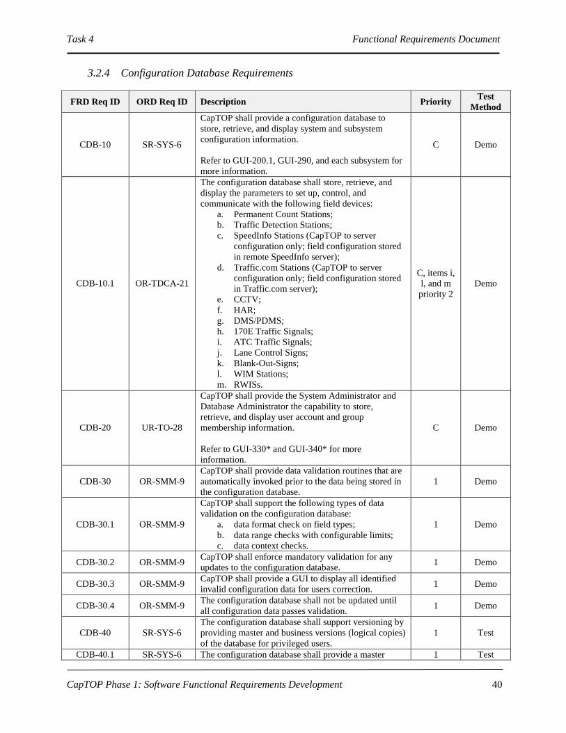
Task 4 Functional Requirements Document
CapTOP Phase 1: Software Functional Requirements Development
40
3.2.4 Configuration Database Requirements
FRD Req ID ORD Req ID Description Priority Test
Method
CDB-10 SR-SYS-6
CapTOP shall provide a configuration database to
store, retrieve, and display system and subsystem
configuration information.
Refer to GUI-200.1, GUI-290, and each subsystem for
more information.
C Demo
CDB-10.1 OR-TDCA-21
The configuration database shall store, retrieve, and
display the parameters to set up, control, and
communicate with the following field devices:
a. Permanent Count Stations;
b. Traffic Detection Stations;
c. SpeedInfo Stations (CapTOP to server
configuration only; field configuration stored
in remote SpeedInfo server);
d. Traffic.com Stations (CapTOP to server
configuration only; field configuration stored
in Traffic.com server);
e. CCTV;
f. HAR;
g. DMS/PDMS;
h. 170E Traffic Signals;
i. ATC Traffic Signals;
j. Lane Control Signs;
k. Blank-Out-Signs;
l. WIM Stations;
m. RWISs.
C, items i,
l, and m
priority 2
Demo
CDB-20 UR-TO-28
CapTOP shall provide the System Administrator and
Database Administrator the capability to store,
retrieve, and display user account and group
membership information.
Refer to GUI-330* and GUI-340* for more
information.
C Demo
CDB-30 OR-SMM-9
CapTOP shall provide data validation routines that are
automatically invoked prior to the data being stored in
the configuration database.
1 Demo
CDB-30.1 OR-SMM-9
CapTOP shall support the following types of data
validation on the configuration database:
a. data format check on field types;
b. data range checks with configurable limits;
c. data context checks.
1 Demo
CDB-30.2 OR-SMM-9 CapTOP shall enforce mandatory validation for any
updates to the configuration database. 1 Demo
CDB-30.3 OR-SMM-9 CapTOP shall provide a GUI to display all identified
invalid configuration data for users correction. 1 Demo
CDB-30.4 OR-SMM-9 The configuration database shall not be updated until
all configuration data passes validation. 1 Demo
CDB-40 SR-SYS-6
The configuration database shall support versioning by
providing master and business versions (logical copies)
of the database for privileged users.
1 Test
CDB-40.1 SR-SYS-6 The configuration database shall provide a master 1 Test
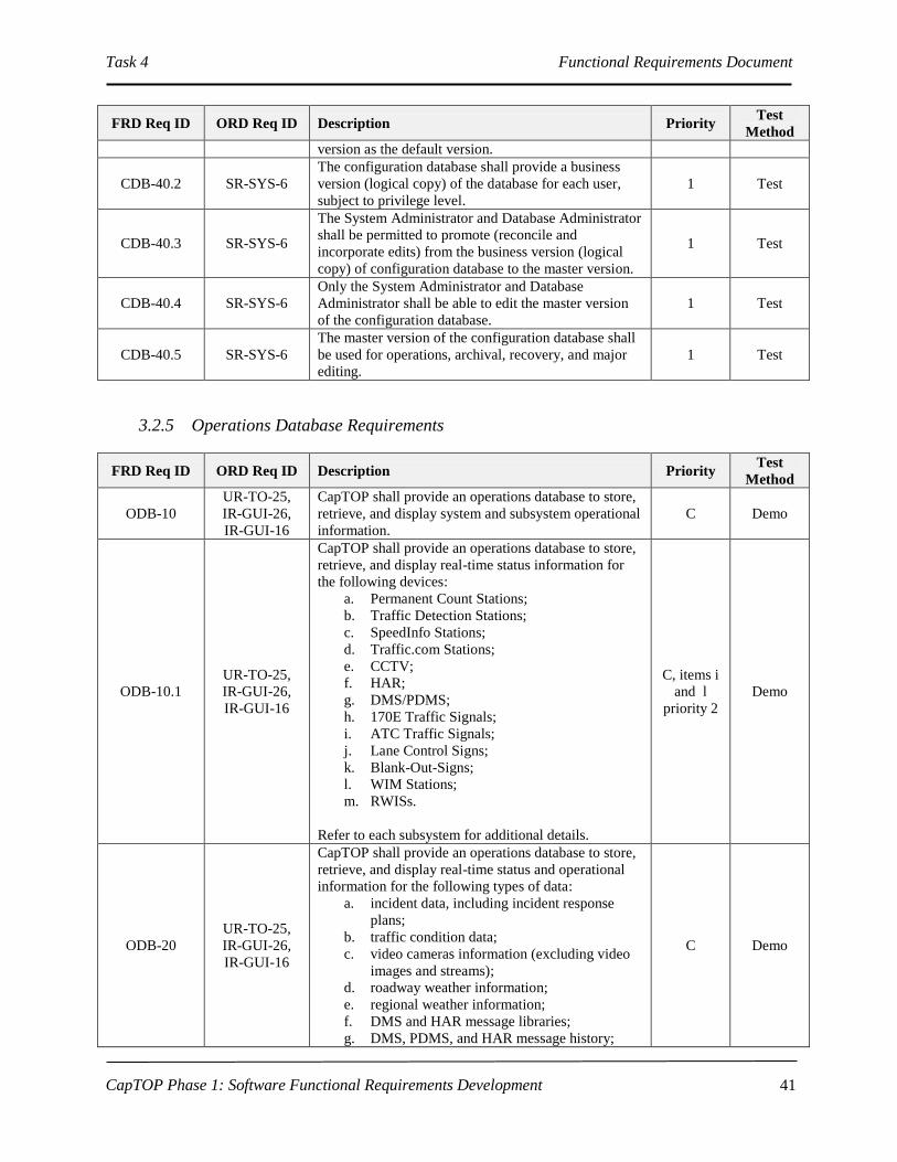
Task 4 Functional Requirements Document
CapTOP Phase 1: Software Functional Requirements Development
41
FRD Req ID ORD Req ID Description Priority Test
Method
version as the default version.
CDB-40.2 SR-SYS-6 The configuration database shall provide a business
version (logical copy) of the database for each user,
subject to privilege level.
1 Test
CDB-40.3 SR-SYS-6
The System Administrator and Database Administrator
shall be permitted to promote (reconcile and
incorporate edits) from the business version (logical
copy) of configuration database to the master version.
1 Test
CDB-40.4 SR-SYS-6
Only the System Administrator and Database
Administrator shall be able to edit the master version
of the configuration database.
1 Test
CDB-40.5 SR-SYS-6
The master version of the configuration database shall
be used for operations, archival, recovery, and major
editing.
1 Test
3.2.5 Operations Database Requirements
FRD Req ID ORD Req ID Description Priority Test
Method
ODB-10
UR-TO-25,
IR-GUI-26,
IR-GUI-16
CapTOP shall provide an operations database to store,
retrieve, and display system and subsystem operational
information.
C Demo
ODB-10.1
UR-TO-25,
IR-GUI-26,
IR-GUI-16
CapTOP shall provide an operations database to store,
retrieve, and display real-time status information for
the following devices:
a. Permanent Count Stations;
b. Traffic Detection Stations;
c. SpeedInfo Stations;
d. Traffic.com Stations;
e. CCTV;
f. HAR;
g. DMS/PDMS;
h. 170E Traffic Signals;
i. ATC Traffic Signals;
j. Lane Control Signs;
k. Blank-Out-Signs;
l. WIM Stations;
m. RWISs.
Refer to each subsystem for additional details.
C, items i
and l
priority 2
Demo
ODB-20
UR-TO-25,
IR-GUI-26,
IR-GUI-16
CapTOP shall provide an operations database to store,
retrieve, and display real-time status and operational
information for the following types of data:
a. incident data, including incident response
plans;
b. traffic condition data;
c. video cameras information (excluding video
images and streams);
d. roadway weather information;
e. regional weather information;
f. DMS and HAR message libraries;
g. DMS, PDMS, and HAR message history;
C Demo

Task 4 Functional Requirements Document
CapTOP Phase 1: Software Functional Requirements Development
42
FRD Req ID ORD Req ID Description Priority Test
Method
h. travel time data;
i. measures of effectiveness;
Refer to INM-30.2.1, INM-100, INM-580, INM-360,
RWI-30.2., RWI-20, CCT-30.2.1, CCT-40, DMS-270,
DMS-280, HAR-260, HAR-270, SYS-170, HAR-250,
SIG-180, RWI-120, GUI 150 and each subsystem for
additional details.
ODB-30 OR-SMM-9
CapTOP shall provide data validation routines that are
automatically invoked prior to the data being stored in
the operations database.
1 Demo
ODB-30.1 OR-SMM-9
CapTOP shall support the following types of data
validation on the operations database:
a. data format check on field types;
b. data range checks with configurable limits;
c. data context checks.
1 Demo
ODB-30.2 OR-SMM-9 CapTOP shall enforce mandatory validation for any
updates to the operations database. 1 Demo
ODB-30.3 OR-SMM-9
CapTOP shall provide a GUI to display invalid
operations data initiated by user action for correction
by the operator.
1 Demo
ODB-30.4 OR-SMM-9
The operations database shall not be updated until all
operations data initiated by user action passes
validation.
1 Demo
ODB-30.5 OR-SMM-9
CapTOP shall generate alerts for data failing validation
that are initiated by system action containing an
identification of the field to be updated, value to be
entered, and time of attempt. The data will be
discarded and not entered into the operations database.
1 Demo
ODB-40 SR-SYS-6 The operations database shall support versioning by
providing master and business versions (logical copies)
of the database for privileged users.
1 Demo
ODB-40.1 SR-SYS-6 The operations database shall provide a master version
as the default version. 1 Demo
ODB-40.2 SR-SYS-6 The operations database shall provide a business
version (logical copy) of the database for each user,
subject to privilege level.
1 Demo
ODB-40.3 SR-SYS-6
The System Administrator and Database Administrator
shall be permitted to promote (reconcile and
incorporate edits) from the business version (logical
copy) of operations database to the master version.
1 Demo
ODB-40.4 SR-SYS-6
Only the System Administrator and Database
Administrator shall be able to edit the master version
of the operations database.
1 Demo
ODB-40.5 SR-SYS-6
The master version of the operations database shall be
used for operations, archival, recovery, and major
editing.
1 Demo
ODB-50 OR-DWA-1
The operational database shall store the following
traffic conditions data with roadway location
information:
a. volume;
b. speed;
c. occupancy;
C Demo
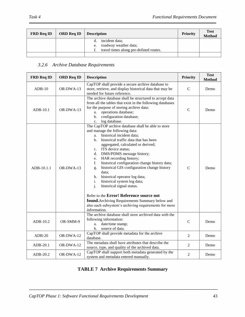
Task 4 Functional Requirements Document
CapTOP Phase 1: Software Functional Requirements Development
43
FRD Req ID ORD Req ID Description Priority Test
Method
d. incident data;
e. roadway weather data;
f. travel times along pre-defined routes.
3.2.6 Archive Database Requirements
FRD Req ID ORD Req ID Description Priority Test
Method
ADB-10 OR-DWA-13
CapTOP shall provide a secure archive database to
store, retrieve, and display historical data that may be
needed for future reference.
C Demo
ADB-10.1 OR-DWA-13
The archive database shall be structured to accept data
from all the tables that exist in the following databases
for the purpose of storing archive data:
a. operations database;
b. configuration database;
c. log database.
C Demo
ADB-10.1.1 OR-DWA-13
The CapTOP archive database shall be able to store
and manage the following data:
a. historical incident data;
b. historical traffic data that has been
aggregated, calculated or derived;
c. ITS device status;
d. DMS/PDMS message history;
e. HAR recording history;
f. historical configuration change history data;
g. historical GIS configuration change history
data;
h. historical operator log data;
i. historical system log data;
j. historical signal status.
Refer to the Error! Reference source not
found.Archiving Requirements Summary below and
also each subsystem’s archiving requirements for more
information.
C Demo
ADB-10.2 OR-SMM-9
The archive database shall store archived data with the
following information:
a. date/time stamp;
b. source of data.
C Demo
ADB-20 OR-DWA-12 CapTOP shall provide metadata for the archive
database. 2 Demo
ADB-20.1 OR-DWA-12 The metadata shall have attributes that describe the
source, type, and quality of the archived data. 2 Demo
ADB-20.2 OR-DWA-12 CapTOP shall support both metadata generated by the
system and metadata entered manually. 2 Demo
TABLE 7 Archive Requirements Summary

Task 4 Functional Requirements Document
CapTOP Phase 1: Software Functional Requirements Development
44
# Data Types Source Need to
Archive
(Yes or No)
Comment
1 Speed, Volume,
Occupancy,
Classification
DDOT Permanent Count
Stations (Video, IR,
Acoustic)
Yes - Not
raw,
aggregated
only
Raw data coming from sensors or servers
is not required to be archived. CapTOP
shall archive only aggregated, derived and
calculated data.
2 Speed, Volume,
Occupancy
DDOT Traffic Detection
Stations (sensor type is
TBD)
Yes - Not
raw,
aggregated
only
Raw data coming from sensors or servers
is not required to be archived. CapTOP
shall archive only aggregated, derived and
calculated data.
3 Speed, Volume,
Occupancy
Traffic.com sensors Yes - Not
raw,
aggregated
only
CapTOP interface is direct with
Traffic.com server. No need to archive
raw data. Will be managed by vendor.
CapTOP shall archive only aggregated,
derived and calculated data.
4 Speed SpeedInfo sensors Yes - Not
raw,
aggregated
only
CapTOP interface is direct with
SpeedInfo server. No need to archive raw
data. Will be managed by vendor.
CapTOP shall archive only aggregated,
derived and calculated data.
5 Average Speed, Freeflow
Speed
INRIX sensors Yes - Not
raw,
aggregated
only
CapTOP interface is direct with INRIX
server. No need to archive raw data. Will
be on tape backup. Will be managed by
vendor. CapTOP shall archive only
aggregated, derived and calculated data.
6 170E Traffic Signal
Status Data
QuicNet Yes –
dynamic
operational
status only
CapTOP shall archive this data. The
signal status from QuicNet are stored in
operations database first and then
archived for one year period. QuicNet
does not store this information.
7 170E Traffic Signal Plan
Data
QuicNet No No need to archive data. Done by
QuicNet.
8 ATC Traffic Signal
Status Data
ATC Signal System Yes –
dynamic
operational
status only
CapTOP shall archive this data. The
signal status from the ATC Signal System
are stored in operations database first and
then archived for one year period.
9 ATC Traffic Signal Plan
Data
New Traffic Signal
System
No No need to archive data. Done by the
ATC Signal System
10 WIM Data CVISN No No need to archive data, unless
calculated, but currently no requirement
to calculate.
11 Incident Data CapTOP Yes CapTOP shall archive this data.
14 Video Recordings CapTOP No Archive of video data not desired
15 System Errors, Warnings,
Alerts
CapTOP Yes CapTOP shall archive this data.
16 System Log CapTOP Yes CapTOP shall archive this data.
17 Operator Log CapTOP Yes CapTOP shall archive this data.
18 RWIS Data SCAN Web Yes CapTOP shall archive this data. Note:
This data is stored in SCAN Web, but is
difficult to access thus CapTOP shall
archive.
19 RWIS Status SCAN Web Yes CapTOP shall archive this data.
20 DMS/PDMS Status CapTOP Yes CapTOP shall archive this data.
21 DMS/PDMS Message CapTOP Yes CapTOP shall archive this data.
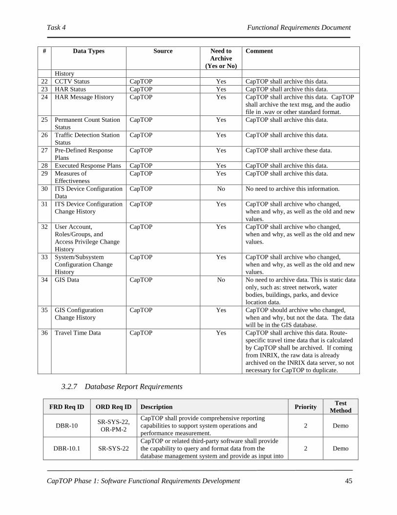
Task 4 Functional Requirements Document
CapTOP Phase 1: Software Functional Requirements Development
45
# Data Types Source Need to
Archive
(Yes or No)
Comment
History
22 CCTV Status CapTOP Yes CapTOP shall archive this data.
23 HAR Status CapTOP Yes CapTOP shall archive this data.
24 HAR Message History CapTOP Yes CapTOP shall archive this data. CapTOP
shall archive the text msg, and the audio
file in .wav or other standard format.
25 Permanent Count Station
Status
CapTOP Yes CapTOP shall archive this data.
26 Traffic Detection Station
Status
CapTOP Yes CapTOP shall archive this data.
27 Pre-Defined Response
Plans
CapTOP Yes CapTOP shall archive these data.
28 Executed Response Plans CapTOP Yes CapTOP shall archive this data.
29 Measures of
Effectiveness
CapTOP Yes CapTOP shall archive this data.
30 ITS Device Configuration
Data
CapTOP No No need to archive this information.
31 ITS Device Configuration
Change History
CapTOP Yes CapTOP shall archive who changed,
when and why, as well as the old and new
values.
32 User Account,
Roles/Groups, and
Access Privilege Change
History
CapTOP Yes CapTOP shall archive who changed,
when and why, as well as the old and new
values.
33 System/Subsystem
Configuration Change
History
CapTOP Yes CapTOP shall archive who changed,
when and why, as well as the old and new
values.
34 GIS Data CapTOP No No need to archive data. This is static data
only, such as: street network, water
bodies, buildings, parks, and device
location data.
35 GIS Configuration
Change History
CapTOP Yes CapTOP should archive who changed,
when and why, but not the data. The data
will be in the GIS database.
36 Travel Time Data CapTOP Yes CapTOP shall archive this data. Route-
specific travel time data that is calculated
by CapTOP shall be archived. If coming
from INRIX, the raw data is already
archived on the INRIX data server, so not
necessary for CapTOP to duplicate.
3.2.7 Database Report Requirements
FRD Req ID ORD Req ID Description Priority Test
Method
DBR-10 SR-SYS-22,
OR-PM-2
CapTOP shall provide comprehensive reporting
capabilities to support system operations and
performance measurement.
2 Demo
DBR-10.1 SR-SYS-22
CapTOP or related third-party software shall provide
the capability to query and format data from the
database management system and provide as input into
2 Demo

Task 4 Functional Requirements Document
CapTOP Phase 1: Software Functional Requirements Development
46
FRD Req ID ORD Req ID Description Priority Test
Method
various reports.
DBR-10.2 SR-SYS-22 CapTOP shall provide predefined reports. C Demo
DBR-10.3 SR-SYS-22 CapTOP shall provide parameterized reports. C Demo
DBR-10.4 SR-SYS-22 CapTOP or related third-party software shall provide
an ad-hoc report capability. 2 Demo
DBR-10.5 SR-SYS-22
CapTOP or related third-party software shall provide a
GUI to customize reports by allowing the operator to
customize both the query and the format of data.
2 Demo
DBR-10.6 SR-SYS-22 CapTOP or related third-party software shall store
previously built custom reports. 2 Demo
DBR-10.7 SR-SYS-22
CapTOP or related third-party software shall provide
the capability to store preformatted or predefined
queries.
2 Demo
DBR-10.8 SR-SYS-22
CapTOP and related third-party software (if used) shall
provide the capability to sort on any field in tabular-
based report for workstation display or printing.
2 Demo
DBR-10.9 SR-SYS-22 CapTOP or related third-party software shall include a
COTS-based, easy to use, report writing tool. 2 Demo
DBR-20 SR-SYS-22
CapTOP and related third-party software (if used) shall
support the following capabilities for all reports:
a. be able to display all reports in a tabular
format;
b. be able to display graphical reports in a
Microsoft Excel-like 2-dimensional or 3-
dimensional format, including at least bar
charts and pie charts;
c. be able to print all reports in landscape or
portrait modes;
d. include the report name and date generated on
the header;
e. support a template capability for each report,
allowing the user to select which fields to
display;
f. include the page number on the footer.
2 Demo
DBR-30
OR-PM-1,
OR-PM-4,
OR-PM-6,
OR-PM-2
CapTOP shall have the capability to produce ITS
device performance measurement reports over a
specified time period.
2 Demo
DBR-30.1
OR-PM-1,
OR-PM-4,
OR-PM-6,
OR-PM-2
CapTOP shall have the capability to produce
DMS/PDMS subsystem performance reports using the
following performance measures:
a. Availability of DMS (mean operational
time);
b. Mean Time Between Failures (MTBF);
c. Mean Time To Repair (MTTR).
2 Demo
DBR-30.2
OR-PM-1,
OR-PM-4,
OR-PM-6
CapTOP shall have the capability to produce CCTV
subsystem performance reports using the following
performance measures:
a. Availability of CCTV (mean operational
time);
b. Mean Time Between Failures (MTBF);
c. Mean Time To Repair (MTTR).
2 Demo
DBR-30.3 OR-PM-1, CapTOP shall have the capability to produce HAR 2 Demo

Task 4 Functional Requirements Document
CapTOP Phase 1: Software Functional Requirements Development
47
FRD Req ID ORD Req ID Description Priority Test
Method
OR-PM-4,
OR-PM-6
subsystem performance reports using the following
performance measures:
a. Availability of HAR (mean operational time);
b. Mean Time Between Failures (MTBF);
c. Mean Time To Repair (MTTR).
DBR-30.4
OR-PM-1,
OR-PM-4,
OR-PM-6
CapTOP shall have the capability to produce RWIS
subsystem performance reports using the following
performance measures:
a. Availability of RWIS (mean operational
time);
b. Mean Time Between Failures (MTBF);
c. Mean Time To Repair (MTTR).
2 Demo
DBR-30.5
OR-PM-1,
OR-PM-4,
OR-PM-6
CapTOP shall have the capability to produce traffic
detection station subsystem performance reports using
the following performance measures:
a. Availability of traffic detection stations (mean
operational time);
b. Mean Time Between Failures (MTBF);
c. Mean Time To Repair (MTTR).
2 Demo
DBR-30.6
OR-PM-1,
OR-PM-4,
OR-PM-6
CapTOP shall have the capability to produce
permanent count station subsystem performance
reports using the following performance measures:
a. Availability of permanent count stations
(mean operational time);
b. Mean Time Between Failures (MTBF);
c. Mean Time To Repair (MTTR).
2 Demo
DBR-40
OR-DWA-5,
OR-SEPM-3,
OR-TOM-1,
OR-TOM-2
CapTOP shall be able to produce the following
performance reports based on archived data for
evaluating the performance of the operators:
a. number of incidents managed by an Operator
over a specified time period;
b. number of special events managed by an
Operator over a specified time period;
c. number of Operator commands to DMS over
a specified time period;
d. number of Operator commands to PDMS over
a specified time period;
e. number of Operator commands to HAR over
a specified time period;
f. number of Operator commands to CCTV over
a specified time period;
g. number of times an Operator logged in over a
specified time period;
h. number of times an Operator logged out over
a specified time period;
i. number of Operator commands to traffic
signals over a specified time period;
j. number of Operator DMS/PDMS messages
approved;
k. number of Operator HAR recordings rejected;
l. number of incidents opened (moved to
“active” or “reopened”) by an Operator;
m. number of incidents closed (ended, deleted,
2 Demo

Task 4 Functional Requirements Document
CapTOP Phase 1: Software Functional Requirements Development
48
FRD Req ID ORD Req ID Description Priority Test
Method
cancelled, postponed) by an Operator.
DBR-50
UR-TO-25,
UR-TO-31,
OR-TOM-2
CapTOP shall produce traffic management
performance reports for the following performance
measurements:
a. travel times on a specified route over a
specified time period;
b. average speeds on a specified route over a
specified time period;
c. average volume on a specified route over a
specified time period.
d. accident rates on a specified route over a
specified time period.
2 Demo
DBR-60 OR-DWA-7,
OR-TOM-2
CapTOP shall be able to generate the following
customized reports:
a. list of system events sorted by type and
date/time;
b. a report showing the traffic measures of
effectiveness (MOEs) over a specified time
period;
c. list of field device status sorted by subsystem
and status;
d. the number of failed communications sorted
by subsystem over a specified time period.
2 Demo
DBR-70
OR-DOC-4,
IR-GUI-8,
SR-SYS-36,
OR-TOM-2
CapTOP shall produce reports that list the location and
status of the following field devices sorted by
subsystem, device ID, location, and communication
status:
a. Permanent Count Stations;
b. Traffic Detection Stations;
c. SpeedInfo Stations;
d. Traffic.com Stations;
e. CCTV;
f. HAR;
g. DMS/PDMS;
h. 170E Traffic Signals;
i. ATC Traffic Signals;
j. Lane Control Signs;
k. Blank-Out-Signs;
l. WIM Stations;
m. RWISs.
C Demo
DBR-80 OR-DDM-12,
OR-TOM-2
CapTOP shall allow users to create reports that
identify the status of following problem areas that have
not yet been resolved:
a. ITS device failures;
b. communication failures;
c. signal controller failures.
2 Demo
DBR-90 OR-DDM-21
CapTOP shall produce a field device report to display
the errors and alarms from any subsystem over a user-
specified time interval.
C Demo
DBR-100 OR-DOC-5
CapTOP shall produce reports for any ITS devices that
have a command pending in the schedule/future event
queue.
2 Demo
DBR-110 OR-TDCA-20 CapTOP shall produce device configuration reports for C Demo

Task 4 Functional Requirements Document
CapTOP Phase 1: Software Functional Requirements Development
49
FRD Req ID ORD Req ID Description Priority Test
Method
the following ITS devices:
a. Permanent Count Stations;
b. Traffic Detection Stations;
c. SpeedInfo Stations;
d. Traffic.com Stations;
e. CCTV;
f. HAR;
g. DMS/PDMS;
h. 170E Traffic Signals;
i. ATC Traffic Signals;
j. Lane Control Signs;
k. Blank-Out-Signs;
l. WIM Stations;
m. RWISs.
DBR-110.1 OR-TDCA-20
Each device configuration report shall list all
configuration information stored in the database for a
particular device.
Refer to each subsystem for additional details.
C Demo
DBR-120 UR-TO-11,
OR-TID-3
CapTOP shall be able to support subsystem specific
reports.
Refer to the reports section of each subsystem for
additional details.
2 Demo
DBR-130 OR-DDM-21
CapTOP shall provide a system alarm report, over a
specified time period that provides the system alarm
message text, and the date/time when displayed.
2 Demo
DBR-140 OR-DDM-29
CapTOP shall have the capability to query and report
the following information on ITS devices:
a. device ID;
b. equipment type;
c. model number;
d. date purchased;
e. serial number;
f. original equipment manufacturer name,
address, phone number, web address;
g. seller's name, address, phone number, web
address;
h. warranty information;
i. repair history.
C Demo
DBR-150 OR-DDM-15
CapTOP shall be able to generate ITS device
maintenance reports and allow Maintenance Staff to
customize the reports for each ITS subsystem.
2 Demo
DBR-160 OR-SEPM-1,
OR-IM-4
CapTOP shall provide a form for each table in the
database to allow the Database Administrator to query,
display, and print data.
2 Demo
3.2.8 Database Security Requirements
FRD Req ID ORD Req ID Description Priority Test
Method
DBS-10 SR-SYS-33 The CapTOP database shall support role-based C Demo

Task 4 Functional Requirements Document
CapTOP Phase 1: Software Functional Requirements Development
50
FRD Req ID ORD Req ID Description Priority Test
Method
security policies for database access based on the
CapTOP user group definitions.
Refer to GUI-340.
DBS-10.1 SR-SYS-33
The CapTOP database shall provide multiple security
levels to control data access based on CapTOP user
group definitions.
Refer to GUI-340.3.2.
C Demo
DBS-10.2 SR-SYS-33
CapTOP shall allow the System Administrator and
Database Administrator to setup privileges on the
database as a whole or on individual tables in the
database.
C Demo
DBS-10.2.1 SR-SYS-33
CapTOP shall allow database access rights to be
configured on a per group and per table basis and shall
default to the values shown in Error! Reference
source not found. “Default Database Access Rights”
below.
C Demo
DBS-10.3 SR-SYS-33 All database access shall be user ID and password
controlled. C Demo
DBS-20 SR-SYS-33
CapTOP shall maintain statistical data on attempted
unauthorized accesses and provide e-mail notifications
to the Database Administrator and TMC Manager
whenever an attempted unauthorized access occurs.
1 Demo

Task 4 Functional Requirements Document
CapTOP Phase 1: Software Functional Requirements Development
51
TABLE 8 Default Database Access Rights

Task 4 Functional Requirements Document
CapTOP Phase 1: Software Functional Requirements Development
52

Task 4 Functional Requirements Document
CapTOP Phase 1: Software Functional Requirements Development 53
3.2.9 Database Backup and Failure Requirements
FRD Req ID ORD Req ID Description Priority Test
Method
DBF-10
OR-SMM-10,
PR-SYS-6,
PR-SYS-7
CapTOP shall have a primary and mirrored database to
minimize the probability and impact of database
failures.
2 Demo
DBF-10.1
OR-DWA-2,
OR-SMM-10,
PR-SYS-7
CapTOP shall support a database mirroring capability
to perform database failovers from the primary
database to the mirrored database on the backup
server.
2 Demo
DBF-10.2 PR-SYS-4
CapTOP shall have the capability to mirror the
configuration, log, GIS, and operations databases to
minimize the impact of disk failures and database
failures.
2 Demo
DBF-10.3 PR-SYS-4 CapTOP shall have the capability to recover data from
mirrored databases when failure is detected. 2 Demo
DBF-10.4 PR-SYS-4 CapTOP shall mirror all databases, except the archive
database. 2 Demo
DBF-10.4.1 PR-SYS-4,
PR-SYS-6
CapTOP shall have the capability to recover from
database server failures within 10 seconds by failing
over to mirrored database servers that are kept up to
date with the database information.
2 Demo
DBF-10.5 PR-SYS-4 CapTOP shall maintain a database transaction log for
use in recovering lost data. 2 Demo
DBF-10.6 PR-SYS-4,
PR-SYS-6
CapTOP shall utilize the transaction log to restore the
database to a last known state on a database failure. 2 Demo
DBF-20 OR-DWA-2,
OR-SMM-10
CapTOP shall support a database backup capability to
perform automated backups of the active databases to a
storage device (disk, tape).
1 Demo
DBF-20.1 OR-DWA-2,
OR-SMM-10
The backup capability shall allow System
Administrator and Database Administrator to schedule
automatic backups daily, weekly, and monthly.
1 Demo
DBF-20.2 OR-DWA-2,
OR-SMM-10
The backup capability shall support System
Administrator and Database Administrator initiated
backups of active databases.
1 Demo
DBF-20.3 OR-DWA-2,
OR-SMM-10
The backup capability shall allow System
Administrator and Database Administrator initiate
restoration of data from backup databases to active
databases.
1 Demo
DBF-20.4 PR-SYS-4
CapTOP shall provide a verification process that
checks the contents of the active database against the
contents of the backup database.
1 Demo
DBF-20.5 PR-SYS-4
CapTOP shall continue operational functions without
interruption during the performance of database
backup and data migration functions.
1 Demo

Task 4 Functional Requirements Document
CapTOP Phase 1: Software Functional Requirements Development 54
3.2.10 Archiving, Warehousing, Mining Requirements
FRD Req ID ORD Req ID Description Priority Test
Method
DWA-10 OR-DWA-10 CapTOP shall maintain online accessibility of all
archived information. 1 Demo
DWA-10.1 OR-DWA-11
CapTOP shall have the capability to transfer
information from the archive database to the network
accessible storage.
2 Demo
DWA-10.2 OR-DWA-14 CapTOP shall provide the necessary storage to archive
the data for a minimum of 1 year. 1 Analyze
DWA-10.3 OR-DWA-14
CapTOP shall monitor utilization of allocated storage
and send alerts to the System Administrator when
configurable thresholds on usage have been reached.
1 Demo
DWA-20 OR-DWA-11 CapTOP shall utilize an enterprise RDBMS for the
archive database. 1 Demo
DWA-20.1 OR-DWA-11 The enterprise RDBMS shall support data
warehousing. 2 Demo
DWA-30 OR-DWA-18
CapTOP shall provide the data processing functions to
clean, summarize, aggregate, and transform the
incoming data before it is archived.
1 Demo
DWA-40 OR-DWA-20
CapTOP shall provide a data mining capability that
allows users to query information contained within the
archived data for the following purposes:
a. determining incident patterns;
b. determining recurrent congestion patterns;
c. determining patterns with faulty equipment.
2 Demo
DWA-40.1 OR-DWA-20
As part of the data mining capability, CapTOP shall
use data search capabilities and statistical algorithms to
support ad-hoc queries to discover patterns and
correlations in CapTOP data.
2 Demo
DWA-40.2 OR-DWA-20
CapTOP shall provide the capability to query and
format archived data to feed the performance measures
reports.
2 Demo
DWA-40.3 OR-DWA-20
As part of the data mining capability, CapTOP shall
support ad-hoc queries to assist in discovery of
patterns and correlations in CapTOP data.
2 Demo
DWA-50 OR-DWA-19
CapTOP shall be able to fuse different types of data
from different sources together to enable queries
across all data subjects in the data warehouse.
2 Demo
DWA-60 OR-DWA-22
CapTOP shall provide a reporting capability that
produces predefined, customizable, and parameterized
reports using archived data.
2 Demo
DWA-70 OR-DWA-21
CapTOP shall provide a user-friendly point-and-click
query interface to acquire data using ad-hoc queries
from the archive database.
2 Demo
DWA-80 OR-DWA-23
The reporting capability or related third party tool shall
support complex ad-hoc queries that allow users to
build and specify their own queries.
2 Demo
DWA-90 OR-DWA-24
CapTOP shall provide a GUI to display and print the
processed data from archive database in tabular and
graphical formats.
2 Demo
DWA-100 OR-DWA-16
CapTOP or related third party software shall have the
capability to perform automated and manually initiated
migration of data from the active database to archive
C Demo

Task 4 Functional Requirements Document
CapTOP Phase 1: Software Functional Requirements Development 55
FRD Req ID ORD Req ID Description Priority Test
Method
database.
Refer to each subsystem’s archiving requirements for
more detail.
DWA-100.1 OR-DWA-15
CapTOP shall provide the ability to configure the time
interval for which the data moves from the active
database to archive database.
1 Demo
DWA-100.2 OR-DWA-17
CapTOP shall provide a unique configurable parameter
to define the time interval at which each different type
of data is moved from the active database to the
archive database.
1 Demo
DWA-100.3 OR-DWA-16 CapTOP shall archive data into the archive database at
predefined levels of aggregation and summary. 1 Demo
DWA-110 OR-DWA-25
CapTOP shall have the capability to perform retrieval
of data from the active database and the archive
database.
C Demo
DWA-110.1 OR-DWA-6 CapTOP shall allow users with appropriate privilege
levels to retrieve data from the archive database. C Demo
3.3 Graphic User Interface Requirements
3.3.1 General GUI Requirements
FRD Req ID ORD Req ID Description Priority Test
Method
GUI-10 SR-SYS-14 CapTOP shall provide a windows-based interface to
access CapTOP subsystems, functions and data. C Demo
GUI-20 IR-GUI-1, SR-
SYS-14
CapTOP shall incorporate the following types of
displays:
a. graphics-based displays;
b. GIS-based map displays;
c. web-based displays;
d. alphanumeric text-based displays;
e. form-based displays.
C Demo
GUI-20.1 IR-GUI-50
CapTOP shall be able to incorporate the following
GUI components in any of the CapTOP displays:
a. windows;
b. menus;
c. toolbars;
d. icons;
e. graphical objects;
f. dialog boxes;
g. text labels;
h. action buttons/controls;
i. visual alarms;
j. input fields;
k. check boxes;
l. radio buttons;
m. audio alarms.
C Demo

Task 4 Functional Requirements Document
CapTOP Phase 1: Software Functional Requirements Development 56
FRD Req ID ORD Req ID Description Priority Test
Method
GUI-20.2 IR-GUI-1
CapTOP displays shall have the capability to
incorporate text and graphical objects with dynamic
behavior.
C Demo
GUI-20.3 IR-GUI-1 CapTOP displays shall have the capability to
incorporate bmp, jpeg, png, tiff, and wmf files. 1 Demo
GUI-20.4 IR-GUI-1
CapTOP form-based displays shall have the capability
to permit data entry, to invoke command functions,
and to provide system response.
C Demo
GUI-20.5 UR-TO-2
CapTOP shall provide error checks, range checks with
configurable limits, and consistency checks of all
operator input fields before the data is saved.
1 Demo
GUI-20.5.1 UR-TO-3
CapTOP shall provide consistency checks to ensure
entries between fields are consistent based on
programmed limitations.
1 Demo
GUI-20.5.2 UR-TO-3 CapTOP shall provide the ability to spell check any
user input fields. 2 Demo
GUI-20.5.2.1 UR-TO-3 CapTOP shall highlight in RED any words with
spelling errors in each field. 2 Demo
GUI-20.5.3 UR-TO-4
CapTOP shall generate and display error messages to
indicate which fields contain invalid data and allow the
operator to re-enter rejected data.
1 Demo
GUI-20.6 SR-SYS-30
CapTOP web-based windows shall allow users to
access CapTOP from remote locations, subject to
privilege level.
1 Demo
GUI-20.6.1 SR-SYS-31,
IR-GUI-19
CapTOP shall provide a secure web-based interface to
support remote access of CapTOP functions and data
from outside the DDOT network, subject to privilege
level.
1 Demo
GUI-20.6.2 IR-GUI-19 CapTOP shall support web security using HTTPS and
Internet encryption mechanisms. 1 Demo
GUI-20.7 IR-GUI-7 CapTOP web-based windows shall be able to display
geo-referenced map data in real-time. 1 Demo
GUI-20.8 IR-GUI-19
CapTOP web-based windows shall allow multiple
users to simultaneously access CapTOP functions and
data, subject to privilege level.
1 Demo
GUI-20.9 IR-GUI-8
CapTOP alphanumeric text-based displays shall be
able to present text-based information results from data
retrieval and query.
1 Demo
GUI-20.10 IR-GUI-37
CapTOP alphanumeric text-based displays shall be
able to display events, alarms, and subsystem device
status information.
1 Demo
GUI-20.11 IR-GUI-1
CapTOP window displays shall support the following
buttons and dialog prompts:
a. OK – acknowledges system messages;
b. CANCEL - clears user entered fields or
rejects system actions;
c. SAVE - saves all data entered;
d. APPLY – applies user changes to the system,
but does not close the window;
e. CLOSE - closes the current window.
1 Demo
GUI-20.12 IR-GUI-1 CapTOP displays shall have the capability to be
printed. 1 Demo

Task 4 Functional Requirements Document
CapTOP Phase 1: Software Functional Requirements Development 57
FRD Req ID ORD Req ID Description Priority Test
Method
GUI-20.13 IR-GUI-1 CapTOP displays shall have the capability to support a
print preview capability. 2 Demo
GUI-20.14 IR-GUI-1
CapTOP shall display an hour glass or progress bar
whenever a complicated task is invoked that requires
more than 2 seconds for system response.
2 Demo
GUI-20.15 UR-TO-9
The CapTOP GUI shall be designed to ensure that the
TMC Operator can enter a minimum number of
keystrokes, and not be required to memorize any
commands in order to access a function.
1 Demo 1
GUI-20.16 UR-TO-9
The CapTOP GUI shall be designed to minimize the
number of free form text fields (limited to where
absolutely necessary) and maximize the number of
fields that use check boxes, radio buttons and
selections from pull-down lists.
1 Demo 1
GUI-20.16.1 OR-IM-4
CapTOP shall strictly enforce the use of pull-down
menus when any of the following fields are entered by
the user:
a. Street Address/Block;
b. Road Name;
c. Road Direction;
d. Exit Number;
e. Milepost;
f. Closest Intersection/Interchange;
g. Quadrant;
h. Ward.
1 Demo
GUI-20.16.2 OR-IM-4 CapTOP shall restrict the use of free-form text entry
on the fields identified above. 1 Demo
GUI-20.16.3 OR-IM-4
CapTOP shall allow the user to type the 1st 3
characters in each field and the system will provide a
filtered list of selections for that field based on the user
entered characters. This requirement applies only to
those fields that use lookup tables.
2 Demo
GUI-20.16.4 OR-IM-4
CapTOP shall allow the user to select “Other” and
enter in free form text when a desired entry cannot be
found in the list.
1 Demo
GUI-20.16.4.1 OR-IM-4
CapTOP shall send the System Administrator and the
TMC Manager an e-mail with the subject set to “New
Location Identified”, as well as the user name, and the
data entered into the Other field in the e-mail message
body.
1 Demo
GUI-30 IR-GUI-50
CapTOP shall provide the user interface components
that support hierarchical menus, pull-down menus, and
pop-up menus.
1 Demo
GUI-40 IR-GUI-19
CapTOP shall provide for multi-user capabilities
where two or more different users, at two or more
different CapTOP workstations, can simultaneously
access the system through the GUI, subject to operator
access-level restrictions, with a minimum of 20
simultaneous users accommodated.
C Demo

Task 4 Functional Requirements Document
CapTOP Phase 1: Software Functional Requirements Development 58
3.3.2 CapTOP Toolbar Requirements
FRD Req ID ORD Req ID Description Priority Test
Method
GUI-50 IR-GUI-15
CapTOP shall allow users to perform all CapTOP
functions under one common Graphical User Interface
(GUI), using a standard set of control windows, pull-
down menus, push-buttons, and mouse activated icons.
1 Demo
GUI-50.1 IR-GUI-50
CapTOP shall provide a toolbar with pull-down menus
and icons to access all CapTOP subsystems, functions,
data and applications from any CapTOP workstation.
1 Demo
GUI-50.1.1 IR-GUI-15,
IR-GUI-51
CapTOP shall provide a user interface with a toolbar
that provides access to the following subsystems,
functions, data and applications via an icon on the
toolbar and also via a toolbar drop-down menu:
a. Permanent Count Stations;
b. Traffic Detection Stations;
c. SpeedInfo Stations;
d. Traffic.com Stations;
e. CCTV;
f. HAR;
g. DMS/PDMS;
h. RWISs;
i. Regional Weather;
j. StormTrak;
k. Incident Management;
l. Map Display/GIS;
m. Traffic Signals;
n. QuicNet 170E Central Software;
o. ATC Software Central Software (future);
p. Tools:
I. Account Management;
II. System Configuration;
III. Online Users List;
IV. Electronic White Board;
V. Notification/Messaging;
VI. Work Order Management (
CityWorks);
VII. Configuration Management Software;
VIII. System Scheduler;
IX. Event Display.
Refer to subsystem requirements for additional details.
C, items i,
j, and p
priority 1,
item o
priority 2
Demo
GUI-60 IR-GUI-37
CapTOP shall support a system event window that can
display all logged system events, system alarms, and
operator events.
1 Demo
GUI-60.1 IR-GUI-37,
UR-TO-12
The system event window shall display all events and
alarms in a time sequential order. 1 Demo
GUI-60.2 IR-GUI-37
The system event display shall color code events and
alarms as follows:
a. informational event = text in black.
b. warning event or alarm = text in orange;
c. critical error event or alarm = text in red.
1 Demo
GUI-60.3 IR-GUI-37 The system event display shall use a small icon to
distinguish events from alarms in the event display. 1 Demo

Task 4 Functional Requirements Document
CapTOP Phase 1: Software Functional Requirements Development 59
FRD Req ID ORD Req ID Description Priority Test
Method
GUI-60.4 IR-GUI-37,
SR-SYS-19
The system event window shall display the following
fields for event/alarm log entries triggered by user
actions:
a. Username;
b. Date stamp;
c. Time stamp;
d. Workstation ID;
e. Workstation IP address;
f. Action type;
g. Description of action.
C Demo
GUI-60.4.1 IR-GUI-37,
SR-SYS-20
The system event window shall be able to sort and
filter on any of the fields in the above requirement. 1 Demo
GUI-60.5 IR-GUI-37
The system event window shall display the following
fields for event/alarm log entries generated by the
CapTOP applications:
a. Application name;
b. Date stamp;
c. Time stamp;
d. Action type;
e. Description of action.
1 Demo
GUI-60.5.1 IR-GUI-37
The system event window shall provide the ability to
sort and filter on any of the fields in the above
requirement.
1 Demo
GUI-60.6 IR-GUI-37 CapTOP shall provide audible and visual popup alerts
for events designated as system alarms. 1 Demo
GUI-60.6.1 IR-GUI-37
CapTOP shall allow the System Administrator to
enable/disable the audible and visual popup alerts on a
per user basis.
1 Demo
GUI-60.6.2 IR-GUI-37
CapTOP shall allow the System Administrator to
enable/disable the audible and visual popup alerts on a
per subsystem basis.
1 Demo
GUI-60.6.3 IR-GUI-37
CapTOP shall allow the System Administrator to
enable/disable the audible and visual popup alerts on a
per device basis.
1 Demo
GUI-60.6.4 IR-GUI-37 CapTOP shall provide audible and visual popup
message alerts when a system/device status changes. 1 Demo
GUI-60.6.4.1 SR-SYS-17
CapTOP shall support an alarm capability, whereby
the following events can be configured as different
alarm types:
a. Incident alerts;
b. System warnings;
c. System errors;
d. Subsystem warnings;
e. Subsystem failures;
f. Schedule reminders;
g. Device warnings;
h. Device failures.
1 Demo

Task 4 Functional Requirements Document
CapTOP Phase 1: Software Functional Requirements Development 60
FRD Req ID ORD Req ID Description Priority Test
Method
GUI-60.6.4.2 SR-SYS-18
Each CapTOP alarm type shall be able to be
configured for the following methods for notification:
a. event display (including audible and visual
characteristics);
b. pop-up window (including audible and visual
characteristics);
c. e-mail message (including importance
characteristics);
d. text message;
e. electronic notepad.
1 Demo
GUI-60.7 SR-SYS-21
CapTOP shall provide a search window to allow the
user to search the following data for keywords or
phrases:
a. system events;
b. system alarms;
c. operator events;
d. all of the above.
C Demo
GUI-60.8 UR-TO-29
CapTOP shall allow the TMC Operators to view the
following data for the current session:
a. system event logs;
b. error logs;
c. user logs.
1 Demo
GUI-60.9 UR-TO-29
CapTOP shall allow the System Administrator to view
the following data for any time period across multiple
operator sessions:
a. system event logs;
b. error logs;
c. user logs.
1 Demo
GUI-60.10 UR-TO-11 CapTOP shall provide the ability to save default
window sizes and locations on a per user-basis. 1 Demo
GUI-60.11 OR-SMM-7 CapTOP shall provide the System Administrator
unrestricted access to all system functions. 1 Demo
GUI-60.12 OR-DWA-22 CapTOP shall provide a query editor window to view,
create, edit, and run data queries. 1 Demo
GUI-60.13 OR-DWA-21,
OR-DWA-23
The query window shall support complex, ad hoc
queries that allow users to build and specify their own
queries.
1 Demo
GUI-60.14 SR-SYS-18
Unless noted otherwise, CapTOP shall use the
following color coding conventions:
a. green or black text or objects to indicate
nominal values or informational messages;
b. red to indicate critical information for items
that require immediate attention;
c. orange to indicate warnings for items that
require attention.
1 Demo
GUI-60.15 SR-SYS-18
Unless noted otherwise, CapTOP shall use the
following audible conventions:
a. buzzer (configurable by System
Administrator) to indicate critical information
for items that require immediate attention;
b. bell (configurable by System Administrator)
to indicate warnings for items that require
attention.
1 Demo

Task 4 Functional Requirements Document
CapTOP Phase 1: Software Functional Requirements Development 61
FRD Req ID ORD Req ID Description Priority Test
Method
GUI-70 IR-GUI-50 The CapTOP toolbar shall display the name of the user
currently logged in at all times. 1 Demo
GUI-80 IR-GUI-50 The CapTOP toolbar shall display the current
date/time of the system at all times. 1 Demo
GUI-90 IR-GUI-50
The CapTOP toolbar shall have a feature that allows
the user to access a list of users currently logged into
the system.
1 Demo
3.3.3 Map Display Requirements
FRD Req ID ORD Req ID Description Priority Test
Method
GUI-110 IR-GUI-6
CapTOP shall provide a GIS-based map display
window capability available from any CapTOP
workstation.
C Demo
GUI-110.1 IR-GUI-6
The CapTOP map display window shall be launched
by the following methods:
a. via a toolbar icon;
b. via a toolbar menu item.
1 Demo
GUI-120 IR-GUI-6 The CapTOP map display window shall be able to
display GIS-based geo-referenced data. C Demo
GUI-120.1 IR-GUI-25
CapTOP shall provide a map display window with
geographically accurate maps of the following:
a. Street network;
b. Map utility layers;
c. ITS devices;
d. Incidents;
e. Traffic condition data.
C Demo
GUI-120.1.1
IR-GUI-12,
IR-GUI-35,
IR-GUI-46,
IR-GUI-53,
IR-GUI-54
The CapTOP map display shall allow users to turn
on/off the following map layers independently, subject
to privilege level:
a. Street network (each a separate layer):
I. interstates;
II. regional main routes;
III. arterials;
IV. surface streets;
V. residential streets.
b. Map utility layers:
I. parks;
II. aerial photography;
III. ward boundaries;
IV. quadrant boundaries;
V. parking restrictions;
VI. WMATA subway routes*;
VII. WMATA bus routes*;
VIII. WMATA bus route status*;
IX. Transit stations*;
X. utility lines (power, gas, water,
communication, sewage)
XI. utility poles;
XII. water bodies;
XIII. buildings;
XIV. bridges and tunnels;
All C,
items with
* are 2
Demo

Task 4 Functional Requirements Document
CapTOP Phase 1: Software Functional Requirements Development 62
FRD Req ID ORD Req ID Description Priority Test
Method
XV. manholes and conduit runs for power
and communication to ITS devices*;
XVI. truck routes*;
XVII. truck routes with height restrictions*;
XVIII. truck routes with weight restrictions*;
XIX. points of interest.
c. ITS devices (each a separate layer):
I. Permanent Count Stations;
II. Traffic Detection Stations;
III. SpeedInfo Stations;
IV. Traffic.com Stations;
V. CCTV devices;
VI. HAR devices;
VII. DMS/PDMS devices;
VIII. 170E Traffic Signal devices;
IX. ATC Traffic Signal devices*;
X. Lane Control Signals;
XI. Blank-Out-Signs (BOS);
XII. RWIS devices;
XIII. AVL-tracked vehicles (ROPS,
Maintenance Vehicles, Snow Trucks)*.
d. Incidents (1 layer for all):
I. Active construction/maintenance
incidents;
II. Active special events;
III. Active traffic accidents;
IV. Active road closures;
V. Active “other” incident types.
e. Traffic condition data.
GUI-120.1.1.1 IR-GUI-12 CapTOP shall retain map layer selections on a per user
basis, applying the selection at user login. 1 Demo
GUI-120.1.2 IR-GUI-25
The CapTOP map display shall be able to show the
location of reversible lanes, one-way streets,
evacuation routes, snow routes, and lane/turning
restrictions.
C Demo
GUI-120.1.2.1 OR-EM-6
CapTOP shall provide the TMC Operator with a map-
based display to indicate which routes are operating in
a reverse direction.
1 Demo
GUI-120.1.3 IR-GUI-33
The CapTOP map display window shall be able to
display data from multiple sources on different map
layers.
2 Demo
GUI-120.2 IR-GUI-25 CapTOP shall be able to display the street name on the
map when the mouse hovers over a roadway link. 1 Demo
GUI-120.3 IR-GUI-25
CapTOP shall be able to display the intersection name
on the map when the mouse hovers over a traffic signal
controller icon.
1 Demo
GUI-120.4 IR-GUI-25 CapTOP shall be able to pan and zoom the map
display. 1 Demo
GUI-120.4.1 IR-GUI-25
The zoom-in function shall be supported using a
rubber-band style box, where the map will zoom into
an area boxed in by the user.
1 Demo
GUI-120.4.2 IR-GUI-25 The user shall also be able to zoom in the map using a
forward roll of the mouse wheel. 1 Demo
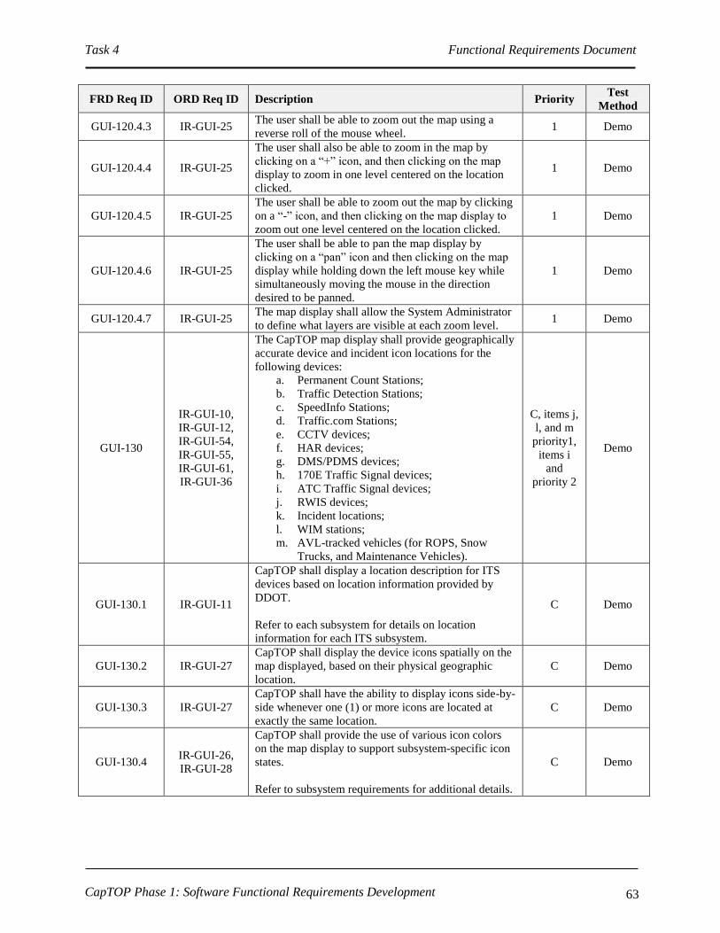
Task 4 Functional Requirements Document
CapTOP Phase 1: Software Functional Requirements Development 63
FRD Req ID ORD Req ID Description Priority Test
Method
GUI-120.4.3 IR-GUI-25 The user shall be able to zoom out the map using a
reverse roll of the mouse wheel. 1 Demo
GUI-120.4.4 IR-GUI-25
The user shall also be able to zoom in the map by
clicking on a “+” icon, and then clicking on the map
display to zoom in one level centered on the location
clicked.
1 Demo
GUI-120.4.5 IR-GUI-25
The user shall be able to zoom out the map by clicking
on a “-” icon, and then clicking on the map display to
zoom out one level centered on the location clicked.
1 Demo
GUI-120.4.6 IR-GUI-25
The user shall be able to pan the map display by
clicking on a “pan” icon and then clicking on the map
display while holding down the left mouse key while
simultaneously moving the mouse in the direction
desired to be panned.
1 Demo
GUI-120.4.7 IR-GUI-25 The map display shall allow the System Administrator
to define what layers are visible at each zoom level. 1 Demo
GUI-130
IR-GUI-10,
IR-GUI-12,
IR-GUI-54,
IR-GUI-55,
IR-GUI-61,
IR-GUI-36
The CapTOP map display shall provide geographically
accurate device and incident icon locations for the
following devices:
a. Permanent Count Stations;
b. Traffic Detection Stations;
c. SpeedInfo Stations;
d. Traffic.com Stations;
e. CCTV devices;
f. HAR devices;
g. DMS/PDMS devices;
h. 170E Traffic Signal devices;
i. ATC Traffic Signal devices;
j. RWIS devices;
k. Incident locations;
l. WIM stations;
m. AVL-tracked vehicles (for ROPS, Snow
Trucks, and Maintenance Vehicles).
C, items j,
l, and m
priority1,
items i
and
priority 2
Demo
GUI-130.1 IR-GUI-11
CapTOP shall display a location description for ITS
devices based on location information provided by
DDOT.
Refer to each subsystem for details on location
information for each ITS subsystem.
C Demo
GUI-130.2 IR-GUI-27
CapTOP shall display the device icons spatially on the
map displayed, based on their physical geographic
location.
C Demo
GUI-130.3 IR-GUI-27
CapTOP shall have the ability to display icons side-by-
side whenever one (1) or more icons are located at
exactly the same location.
C Demo
GUI-130.4 IR-GUI-26,
IR-GUI-28
CapTOP shall provide the use of various icon colors
on the map display to support subsystem-specific icon
states.
Refer to subsystem requirements for additional details.
C Demo

Task 4 Functional Requirements Document
CapTOP Phase 1: Software Functional Requirements Development 64
FRD Req ID ORD Req ID Description Priority Test
Method
GUI-130.5 IR-GUI-28
CapTOP shall provide the use of flashing icons on the
map display to support subsystem-specific icon states.
Refer to subsystem requirements for additional details.
C Demo
GUI-130.6 IR-GUI-31
The CapTOP map display window shall allow users to
access an object’s data (links, ITS devices) directly
from the map display, subject to privilege level.
Refer to subsystem requirements for additional details.
C Demo
GUI-130.6.1 IR-GUI-31
The CapTOP map display window shall allow users to
select any object on the map with related data by point-
and-click manipulation of a mouse, subject to privilege
level.
C Demo
GUI-130.6.2 IR-GUI-16,
IR-GUI-31
CapTOP shall allow the Operator to obtain device ID
and device summary status information by hovering
over the device icon on the map display.
Refer to subsystem requirements for additional details.
1 Demo
GUI-130.6.3 IR-GUI-16,
IR-GUI-31
CapTOP shall allow the Operator to obtain detailed
device status information by one of the following
methods:
a. by selecting a status menu item or button
from the GUI window launched by left
clicking on the device icon on the map
display;
b. by selecting the status item from the pop-up
menu displayed by right clicking on the
device icon on the map display.
Refer to subsystem requirements for additional details.
C Demo
GUI-130.6.4 IR-GUI-16,
IR-GUI-31
The CapTOP map display shall allow each icon to be
clicked to provide the following:
a. access to real-time status data;
b. access to control functions (if applicable);
c. access to icon specific functions.
Refer to subsystem requirements for additional details.
1 Demo
GUI-130.6.4.1 IR-GUI-16,
IR-GUI-31
CapTOP shall allow the Operator to access
configuration/control functions (as applicable) by the
following methods:
a. by selecting a configuration menu item or
button from the GUI window launched by left
clicking on the device icon on the map
display;
b. by selecting the configuration item from the
pop-up menu displayed by right clicking on
the device icon on the map display.
Refer to subsystem requirements for additional details.
1 Demo
GUI-130.6.5 IR-GUI-15 CapTOP shall restrict access to any device control
functions if the device is offline. 1 Demo

Task 4 Functional Requirements Document
CapTOP Phase 1: Software Functional Requirements Development 65
FRD Req ID ORD Req ID Description Priority Test
Method
GUI-130.7 IR-GUI-29,
IR-GUI-3
CapTOP shall automatically refresh ITS device status,
signal status, incident status, link status, AVL status,
and message content for DMS/PDMS/HAR on the
map-display in a configurable time interval which is
based on the polling rate defined in each subsystem.
C Demo
GUI-130.8 IR-GUI-10
If the user enters a latitude/longitude pair for the
device, the device icon location on the map shall be
updated automatically based on the coordinates
specified (and not where there user clicked to create
the icon) when confirmed by a user prompt
verification.
1 Demo
GUI-140 IR-GUI-2
The geo-referenced map data shall conform to DDOT's
GIS standards for seamless information exchange with
citywide spatial databases.
1 Demo
GUI-150 IR-GUI-5 The CapTOP map display window shall allow users to
display traffic condition data. C Demo
GUI-150.1 IR-GUI-42
CapTOP shall be able to display roadway traffic
condition information using color-coded traffic
network links.
C Demo
GUI-150.1.1 IR-GUI-42 CapTOP shall be able to be able to display link-based
speed, volume, and occupancy conditions. C Demo
GUI-150.1.1.1 IR-GUI-42,
OR-CMM-4
CapTOP shall be able to display roadway traffic
condition information using color-coded traffic
network links that display the following when the link
speed layer is display:
a. Maroon = speed is between 0% and 25% of
free flow speed;
b. Red = speed is between 25% and 50% of free
flow speed;
c. Yellow = speed is between 50% and 75% of
free flow speed;
d. Light Green = speed is between 75% and
90% of free flow speed;
e. Dark Green = speed is > 90% of free flow
speed.
C Demo
GUI-150.1.1.2 IR-GUI-42
CapTOP shall be able to display roadway traffic
condition information using color-coded traffic
network links that display the following when the link
volume layer is displayed:
a. green = low volume;
b. yellow = medium volume;
c. red = high volume.
C Demo
GUI-150.1.1.3 IR-GUI-42
CapTOP shall be able to display roadway traffic
condition information using color-coded traffic
network links that display the following when the link
occupancy layer is display:
a. green = low occupancy;
b. yellow = medium occupancy;
c. red = high occupancy.
C Demo

Task 4 Functional Requirements Document
CapTOP Phase 1: Software Functional Requirements Development 66
FRD Req ID ORD Req ID Description Priority Test
Method
GUI-150.2
IR-GUI-16,
OR-DWA-3,
OR-DWA-19
CapTOP shall be able to graphically display in the map
window the following data on a per link basis based on
data fused from all available sensors:
a. average speed for current polling interval;
b. average volume for the current polling
interval;
c. average occupancy for the current polling
interval.
C Demo
GUI-150.2.1 IR-GUI-16
When fusing data from multiple sources, CapTOP
shall derive a combined metric of the data from all
available sources, with the greatest importance given
to the data which indicates the poorest traffic
performance.
2 Demo
GUI-150.3
IR-GUI-16,
IR-GUI-48,
IR-GUI-49
CapTOP shall be able to display roadway traffic
condition data using data from the following sources:
a. speed data from SpeedInfo;
b. speed, volume, and occupancy data from
Traffic.com;
c. speed, volume, and occupancy from DDOT’s
Traffic Detection Stations;
d. speed, volume, occupancy and classification
data from DDOT’s Permanent Count Stations.
e. speed data from Inrix
C Demo
GUI-150.4
IR-GUI-42,
IR-GUI-5, IR-
GUI-48, IR-
GUI-49
Each traffic condition link on the map display shall be
selectable and shall display the following:
a. link ID;
b. text description of the link;
c. road name;
d. direction;
e. average speed;
f. average volume;
g. average occupancy.
1 Demo
GUI-150.5 IR-GUI-3 CapTOP shall be able to display roadway traffic
condition data based on real-time data. C Demo
GUI-150.6 IR-GUI-4 CapTOP shall be able to display roadway traffic
condition data based on historical data. 2 Demo
GUI-150.7 OR-TOM-2,
SR-SYS-25
CapTOP shall produce a traffic condition report, over a
specified time period and a specified area, with a
graphical and tabular display that contains the
following:
a. road name;
b. road direction;
c. link speeds;
d. incident locations;
e. link volumes.
1 Demo
GUI-150.8 IR-GUI-25
The network layer shall allow the authorized users to
add, delete, and modify roadway links via a toolbar
menu.
1 Demo
GUI-160
IR-GUI-54,
IR-GUI-55,
IR-GUI-61
The CapTOP map display window shall be able to
display the location of AVL-equipped vehicles. 2 Demo
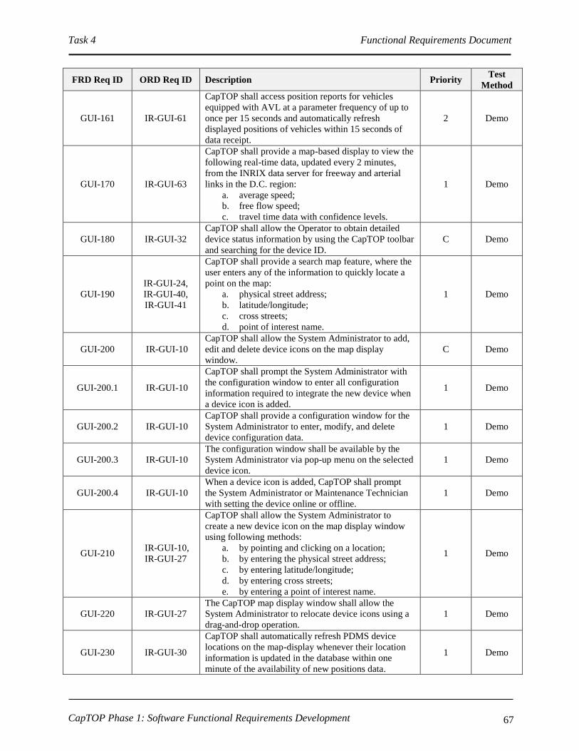
Task 4 Functional Requirements Document
CapTOP Phase 1: Software Functional Requirements Development 67
FRD Req ID ORD Req ID Description Priority Test
Method
GUI-161 IR-GUI-61
CapTOP shall access position reports for vehicles
equipped with AVL at a parameter frequency of up to
once per 15 seconds and automatically refresh
displayed positions of vehicles within 15 seconds of
data receipt.
2 Demo
GUI-170 IR-GUI-63
CapTOP shall provide a map-based display to view the
following real-time data, updated every 2 minutes,
from the INRIX data server for freeway and arterial
links in the D.C. region:
a. average speed;
b. free flow speed;
c. travel time data with confidence levels.
1 Demo
GUI-180 IR-GUI-32
CapTOP shall allow the Operator to obtain detailed
device status information by using the CapTOP toolbar
and searching for the device ID.
C Demo
GUI-190
IR-GUI-24,
IR-GUI-40,
IR-GUI-41
CapTOP shall provide a search map feature, where the
user enters any of the information to quickly locate a
point on the map:
a. physical street address;
b. latitude/longitude;
c. cross streets;
d. point of interest name.
1 Demo
GUI-200 IR-GUI-10
CapTOP shall allow the System Administrator to add,
edit and delete device icons on the map display
window.
C Demo
GUI-200.1 IR-GUI-10
CapTOP shall prompt the System Administrator with
the configuration window to enter all configuration
information required to integrate the new device when
a device icon is added.
1 Demo
GUI-200.2 IR-GUI-10
CapTOP shall provide a configuration window for the
System Administrator to enter, modify, and delete
device configuration data.
1 Demo
GUI-200.3 IR-GUI-10
The configuration window shall be available by the
System Administrator via pop-up menu on the selected
device icon.
1 Demo
GUI-200.4 IR-GUI-10
When a device icon is added, CapTOP shall prompt
the System Administrator or Maintenance Technician
with setting the device online or offline.
1 Demo
GUI-210 IR-GUI-10,
IR-GUI-27
CapTOP shall allow the System Administrator to
create a new device icon on the map display window
using following methods:
a. by pointing and clicking on a location;
b. by entering the physical street address;
c. by entering latitude/longitude;
d. by entering cross streets;
e. by entering a point of interest name.
1 Demo
GUI-220 IR-GUI-27
The CapTOP map display window shall allow the
System Administrator to relocate device icons using a
drag-and-drop operation.
1 Demo
GUI-230 IR-GUI-30
CapTOP shall automatically refresh PDMS device
locations on the map-display whenever their location
information is updated in the database within one
minute of the availability of new positions data.
1 Demo

Task 4 Functional Requirements Document
CapTOP Phase 1: Software Functional Requirements Development 68
FRD Req ID ORD Req ID Description Priority Test
Method
GUI-240 OR-DDM-20
CapTOP shall allow the System Administrator to
perform the following changes and have the devices
used properly within CapTOP without having to
perform a system shutdown/restart:
a. add, remove and change device icons on the
map display;
b. add, remove and change ITS device
configuration information stored in the central
system;
c. add, remove, and change ITS device
configuration information stored in the
device;
d. add, remove, and change user accounts.
C Demo
3.3.4 CapTOP Web Interface Requirements
FRD Req ID ORD Req ID Description Priority Test
Method
GUI-250 SR-SYS-29 CapTOP shall provide the ability to support remote
users. C Demo
GUI-250.1 UR-TO-32
CapTOP shall provide remote users, connecting via the
District's existing VPN and using the secure token ID
system, the ability to update incident information and
control ITS devices, subject to user privileges.
C Demo
GUI-250.1.1 UR-TO-32
When accessing CapTOP from remote locations, the
workstation will be identified as Accessed via VPN for
system usage and storage in logs
1 Demo
GUI-250.2
UR-TO-31,
SR-SYS-29.
OR-CMM-4
CapTOP shall provide remote users, not connected to
the DDOT network, the ability to view (view only) the
following without username/password authentication:
a. incident data;
b. traffic condition data;
c. ITS device status;
d. live video;
e. roadway weather information;
f. travel time data;
g. current DMS messages;
h. current HAR messages;
i. regional weather information.
C Demo
GUI-250.3 IR-GUI-7
CapTOP shall allow the display of map-based traffic
condition data to the external agencies and the public
in real-time via the Internet.
1 Demo
GUI-250.4 IR-GUI-59
CapTOP shall provide a map-based display via the
Internet to provide information about special event
traffic control plans ahead of time to the public.
2 Demo
GUI-250.5 OR-IM-61,
SR-SYS-29
CapTOP shall provide a web interface to display a
read-only view of all layers using color coded icons
identical to the interface used by TMC Operators.
1 Demo
GUI-250.6 SR-SYS-29
The web interface shall provide a text box to show a
summary of ITS device information by clicking on the
appropriate device icon.
1 Demo

Task 4 Functional Requirements Document
CapTOP Phase 1: Software Functional Requirements Development 69
FRD Req ID ORD Req ID Description Priority Test
Method
GUI-250.7 SR-SYS-29
The web interface shall automatically refresh ITS
device status according to a time interval set by the
System Administrator.
1 Demo
GUI-250.8 SR-SYS-29
The web interface shall show status information only;
all configuration and control information shall be
disabled.
1 Demo
GUI-260 SR-SYS-32,
OR-CMM-5
CapTOP shall provide a web-based interface to view
information from the following partners/systems:
a. SHA;
b. VDOT;
c. MWCOG;
d. RITIS;
e. DDOT CIPS;
f. DDOT Snow Operations;
g. DC UCC;
h. DC Public Safety;
i. NCR Emergency Response;
j. WASA;
k. NAWAS;
l. WMATA;
m. DPW;
n. DC Streetcar Operations;
o. DC Tunnel Operations;
p. DC Parking Operations.
2, item p
priority 3 Demo
GUI-260.1 UR-TO-31,
SR-SYS-29
CapTOP shall provide a web-based interface to view
the following information from partners in other
jurisdictions:
a. incident data;
b. traffic condition data;
c. ITS device status;
d. live video;
e. roadway weather information;
f. regional weather information.
1 Demo
3.3.5 GUI Subsystem Requirements
FRD Req ID ORD Req ID Description Priority Test
Method
GUI-270 IR-GUI-15,
IR-GUI-51
CapTOP shall provide a status window that displays
the list of devices and their operational status for each
subsystem, subject to user privileges.
Refer to subsystem requirements for additional details.
1 Demo
GUI-270.1 IR-GUI-15,
IR-GUI-51
CapTOP shall display device specific status when
requested by a user by clicking on a device ID in the
subsystem status window, subject to user privileges.
Refer to subsystem requirements for additional details.
1 Demo
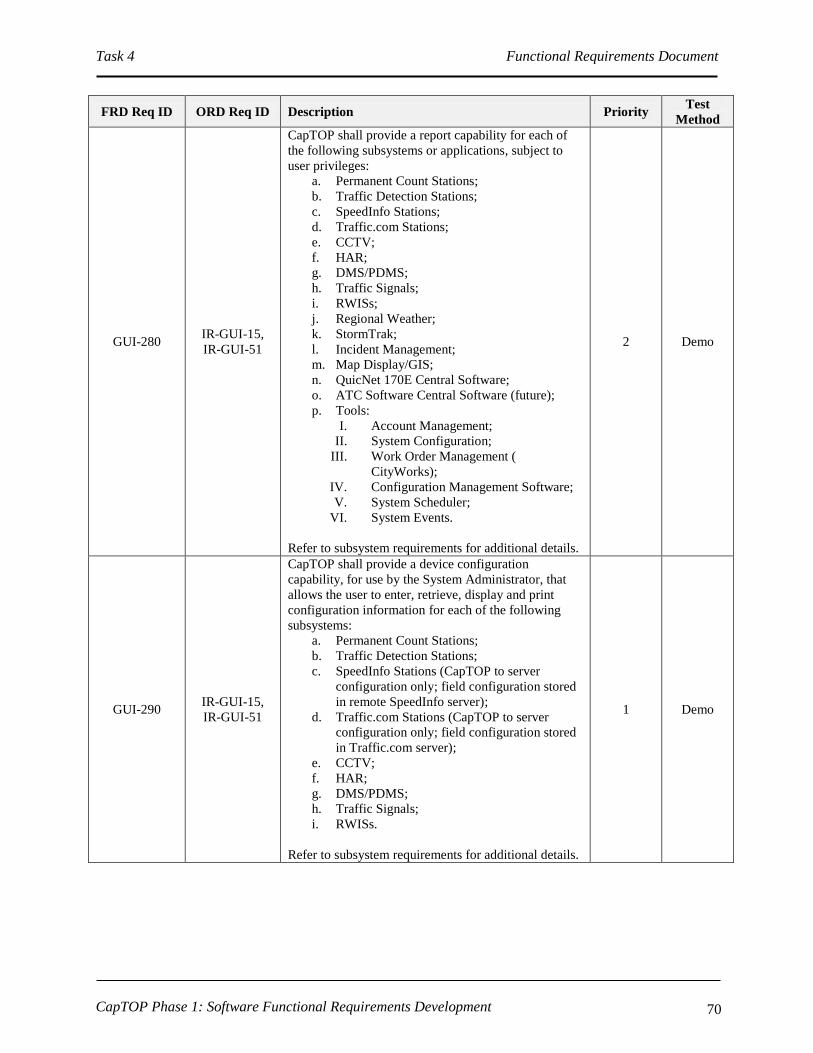
Task 4 Functional Requirements Document
CapTOP Phase 1: Software Functional Requirements Development 70
FRD Req ID ORD Req ID Description Priority Test
Method
GUI-280 IR-GUI-15,
IR-GUI-51
CapTOP shall provide a report capability for each of
the following subsystems or applications, subject to
user privileges:
a. Permanent Count Stations;
b. Traffic Detection Stations;
c. SpeedInfo Stations;
d. Traffic.com Stations;
e. CCTV;
f. HAR;
g. DMS/PDMS;
h. Traffic Signals;
i. RWISs;
j. Regional Weather;
k. StormTrak;
l. Incident Management;
m. Map Display/GIS;
n. QuicNet 170E Central Software;
o. ATC Software Central Software (future);
p. Tools:
I. Account Management;
II. System Configuration;
III. Work Order Management (
CityWorks);
IV. Configuration Management Software;
V. System Scheduler;
VI. System Events.
Refer to subsystem requirements for additional details.
2 Demo
GUI-290 IR-GUI-15,
IR-GUI-51
CapTOP shall provide a device configuration
capability, for use by the System Administrator, that
allows the user to enter, retrieve, display and print
configuration information for each of the following
subsystems:
a. Permanent Count Stations;
b. Traffic Detection Stations;
c. SpeedInfo Stations (CapTOP to server
configuration only; field configuration stored
in remote SpeedInfo server);
d. Traffic.com Stations (CapTOP to server
configuration only; field configuration stored
in Traffic.com server);
e. CCTV;
f. HAR;
g. DMS/PDMS;
h. Traffic Signals;
i. RWISs.
Refer to subsystem requirements for additional details.
1 Demo
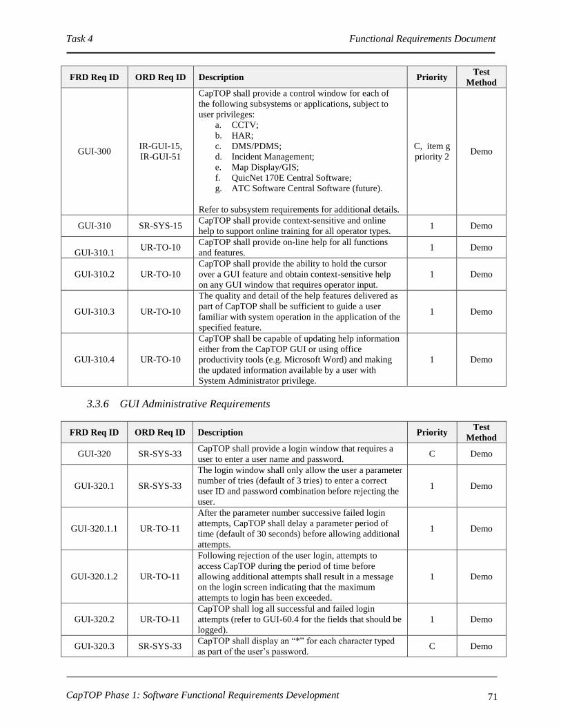
Task 4 Functional Requirements Document
CapTOP Phase 1: Software Functional Requirements Development 71
FRD Req ID ORD Req ID Description Priority Test
Method
GUI-300 IR-GUI-15,
IR-GUI-51
CapTOP shall provide a control window for each of
the following subsystems or applications, subject to
user privileges:
a. CCTV;
b. HAR;
c. DMS/PDMS;
d. Incident Management;
e. Map Display/GIS;
f. QuicNet 170E Central Software;
g. ATC Software Central Software (future).
Refer to subsystem requirements for additional details.
C, item g
priority 2 Demo
GUI-310 SR-SYS-15 CapTOP shall provide context-sensitive and online
help to support online training for all operator types. 1 Demo
GUI-310.1 UR-TO-10
CapTOP shall provide on-line help for all functions
and features. 1 Demo
GUI-310.2 UR-TO-10
CapTOP shall provide the ability to hold the cursor
over a GUI feature and obtain context-sensitive help
on any GUI window that requires operator input.
1 Demo
GUI-310.3 UR-TO-10
The quality and detail of the help features delivered as
part of CapTOP shall be sufficient to guide a user
familiar with system operation in the application of the
specified feature.
1 Demo
GUI-310.4 UR-TO-10
CapTOP shall be capable of updating help information
either from the CapTOP GUI or using office
productivity tools (e.g. Microsoft Word) and making
the updated information available by a user with
System Administrator privilege.
1 Demo
3.3.6 GUI Administrative Requirements
FRD Req ID ORD Req ID Description Priority Test
Method
GUI-320 SR-SYS-33 CapTOP shall provide a login window that requires a
user to enter a user name and password. C Demo
GUI-320.1 SR-SYS-33
The login window shall only allow the user a parameter
number of tries (default of 3 tries) to enter a correct
user ID and password combination before rejecting the
user.
1 Demo
GUI-320.1.1 UR-TO-11
After the parameter number successive failed login
attempts, CapTOP shall delay a parameter period of
time (default of 30 seconds) before allowing additional
attempts.
1 Demo
GUI-320.1.2 UR-TO-11
Following rejection of the user login, attempts to
access CapTOP during the period of time before
allowing additional attempts shall result in a message
on the login screen indicating that the maximum
attempts to login has been exceeded.
1 Demo
GUI-320.2 UR-TO-11
CapTOP shall log all successful and failed login
attempts (refer to GUI-60.4 for the fields that should be
logged).
1 Demo
GUI-320.3 SR-SYS-33 CapTOP shall display an “*” for each character typed
as part of the user’s password. C Demo

Task 4 Functional Requirements Document
CapTOP Phase 1: Software Functional Requirements Development 72
FRD Req ID ORD Req ID Description Priority Test
Method
GUI-320.4 SR-SYS-33
CapTOP shall prompt the user to change their
password after a configurable amount of time expires
since the last password change.
1 Demo
GUI-320.4.1 SR-SYS-33
When a CapTOP password expires, the system shall
force the user to change their password, and not permit
login until accomplished.
1 Demo
GUI-320.4.2 SR-SYS-33
When a CapTOP password expires the system shall
require the user to enter their old password once and
their new password twice, each in a separate field.
1 Demo
GUI-320.4.3 SR-SYS-33
If the old password is correct, and new password is a
perfect match in the two separate fields, CapTOP shall
update the password for that user and permit login;
otherwise, an error message will be displayed and the
user can retry up to a parameter number of times
(default of 3 times) total before a parameter length
(default of 30-seconds) timeout occurs.
1 Demo
GUI-320.4.4 SR-SYS-33 The CapTOP password expiration duration shall be
configurable from zero (never expires) to 1 year. 1 Demo
GUI-320.4.5 SR-SYS-33 The CapTOP password expiration duration shall
default to require a change every 6 months 1 Demo
GUI-320.4.6 SR-SYS-33
CapTOP shall reject attempts to set the new password
to the value of the expiring password or the value of a
password used by the specific user in a parameter time
period (default of 1 year).
1 Demo
GUI-320.4.7 SR-SYS-33
CapTOP shall reject attempts to set passwords to a
value less that 8 characters in length and that do not
include at least one number and one special character
(!@#$%^&*()+-*/<>:;\[]).
1 Demo
GUI-320.4.8 SR-SYS-33 CapTOP shall provide a menu option for a user to
replace his password at user initiation. 1 Demo
GUI-330 OR-SMM-5,
UR-TO-28
CapTOP shall provide an administration window for
System Administrators to manage user accounts. C Demo
GUI-330.1 OR-SMM-1 CapTOP shall provide the ability for the System
Administrator to create, modify or delete user accounts. C Demo
GUI-330.2 OR-SMM-1
Each account shall contain the following attribute
information:
a. User ID;
b. Username;
c. E-mail address;
d. Telephone number;
e. Password;
f. Group membership (refer to GUI-340.2.1);
g. Privileges (refer to GUI-340.3.1).
C Demo
GUI-330.2.1 OR-SMM-1 All user passwords shall be stored and displayed in an
encrypted fashion. 1 Demo
GUI-330.3 OR-SMM-1 CapTOP shall allow the System Administrator to reset
user passwords. 1 Demo
GUI-340 SR-SYS-33 CapTOP shall support multi-levels of privileges to
control user access. C Demo
GUI-340.1 SR-SYS-34
CapTOP shall provide the capability for the System
Administrator to assign privilege levels when a user
account is created.
C Demo
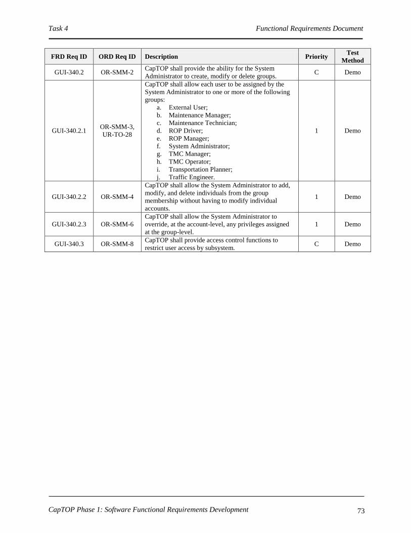
Task 4 Functional Requirements Document
CapTOP Phase 1: Software Functional Requirements Development 73
FRD Req ID ORD Req ID Description Priority Test
Method
GUI-340.2 OR-SMM-2 CapTOP shall provide the ability for the System
Administrator to create, modify or delete groups. C Demo
GUI-340.2.1 OR-SMM-3,
UR-TO-28
CapTOP shall allow each user to be assigned by the
System Administrator to one or more of the following
groups:
a. External User;
b. Maintenance Manager;
c. Maintenance Technician;
d. ROP Driver;
e. ROP Manager;
f. System Administrator;
g. TMC Manager;
h. TMC Operator;
i. Transportation Planner;
j. Traffic Engineer.
1 Demo
GUI-340.2.2 OR-SMM-4
CapTOP shall allow the System Administrator to add,
modify, and delete individuals from the group
membership without having to modify individual
accounts.
1 Demo
GUI-340.2.3 OR-SMM-6
CapTOP shall allow the System Administrator to
override, at the account-level, any privileges assigned
at the group-level.
1 Demo
GUI-340.3 OR-SMM-8 CapTOP shall provide access control functions to
restrict user access by subsystem. C Demo

Task 4 Functional Requirements Document
CapTOP Phase 1: Software Functional Requirements Development 74
FRD Req ID ORD Req ID Description Priority Test
Method
GUI-340.3.1 SR-SYS-35,
OR-SMM-5
CapTOP shall provide the capability for each
subsystem and critical function to have user account-
level settings for read-only, control (write), and
override.
Subsystem Access Right
1. Access incident status;
2. Transmit alerts and notifications.
3. Enable or disable the ability to classify incidents;
4. Access account management functions;
5. Execute incident response plans;
6. Enable or disable the ability to generate reports;
7. Access archive data;
8. Access system administration functions in the system;
9. Update configuration information for the system;
10. Update configuration information for all ITS devices;
11. Access HAR events and alarm logs;
12. Listen to current HAR recording;
13. Transmit a HAR recording;
14. Create a HAR recording;
15. Turn HAR transmitters on/off;
16. Edit HAR message schedule;
17. Access HAR status;
18. Override control of a locked HAR;
19. Access HAR maintenance/diagnostic status;
20. Access DMS/PDMS events and alarm logs;
21. Transmit DMS/PDMS message;
22. Create DMS/PDMS message;
23. Edit DMS/PDMS message schedule;
24. Override control of a locked DMS/PDMS;
25. Access DMS/PDMS status;
26. Access DMS/PDMS maintenance/diagnostic commands;
27. Access CCTV events and alarms;
28. Access live and recorded video;
29. Camera controls;
30. Edit CCTV tour schedule;
31. Override control of a locked camera;
32. Camera status;
33. CCTV maintenance/diagnostic interface;
34. Access traffic signal events and alarms;
35. Access traffic signal status;
36. Access traffic detection station events and alarms;
37. Access traffic detection station status;
38. Access traffic detection station data;
39. Access permanent count station events and alarms;
40. Access permanent count station status;
41. Access permanent count station data;
42. Access SpeedInfo station events and alarms;
43. Access SpeedInfo station status;
44. Access SpeedInfo station data;
45. Access Traffic.com station events and alarms;
46. Access Traffic.com station status;
47. Access Traffic.com station data;
48. Access RWIS events and alarms;
49. Access RWIS status;
Traffic.com Stations
SpeedInfo Stations
Permanent Count
Stations
Incident
Management
System
Administration
Road Weather
Information Status
CCTV
DMS
HAR
Traffic Signals
Traffic Detection
Stations
C Demo
GUI-340.3.2 OR-SMM-5
CapTOP shall support role-based access by allowing
each group to be configured with default settings of
each privilege (refer to GUI-340.3.1 for each
privilege).
C Demo
GUI-350 OR-DOC-22,
OR-DOC-30
CapTOP shall be able to define and schedule planned
incidents and subsystem device commands for
execution using a schedule editor.
Refer to subsystem requirements for additional details.
C Demo
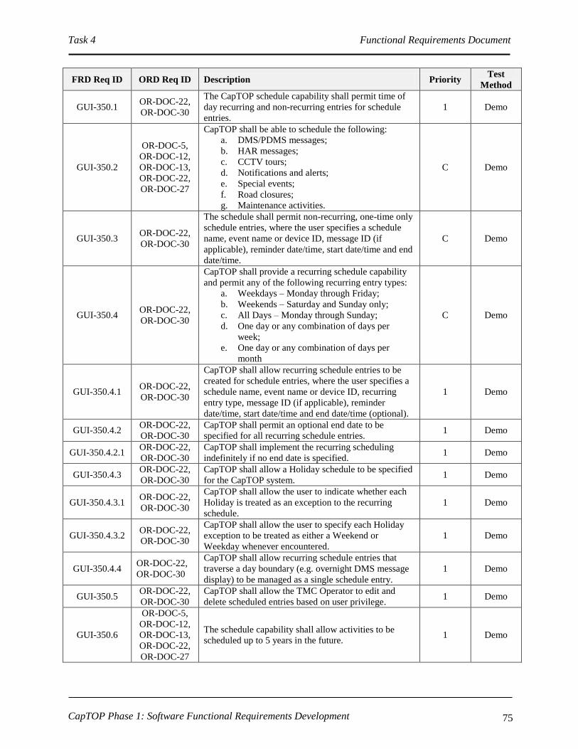
Task 4 Functional Requirements Document
CapTOP Phase 1: Software Functional Requirements Development 75
FRD Req ID ORD Req ID Description Priority Test
Method
GUI-350.1 OR-DOC-22,
OR-DOC-30
The CapTOP schedule capability shall permit time of
day recurring and non-recurring entries for schedule
entries.
1 Demo
GUI-350.2
OR-DOC-5,
OR-DOC-12,
OR-DOC-13,
OR-DOC-22,
OR-DOC-27
CapTOP shall be able to schedule the following:
a. DMS/PDMS messages;
b. HAR messages;
c. CCTV tours;
d. Notifications and alerts;
e. Special events;
f. Road closures;
g. Maintenance activities.
C Demo
GUI-350.3 OR-DOC-22,
OR-DOC-30
The schedule shall permit non-recurring, one-time only
schedule entries, where the user specifies a schedule
name, event name or device ID, message ID (if
applicable), reminder date/time, start date/time and end
date/time.
C Demo
GUI-350.4 OR-DOC-22,
OR-DOC-30
CapTOP shall provide a recurring schedule capability
and permit any of the following recurring entry types:
a. Weekdays – Monday through Friday;
b. Weekends – Saturday and Sunday only;
c. All Days – Monday through Sunday;
d. One day or any combination of days per
week;
e. One day or any combination of days per
month
C Demo
GUI-350.4.1 OR-DOC-22,
OR-DOC-30
CapTOP shall allow recurring schedule entries to be
created for schedule entries, where the user specifies a
schedule name, event name or device ID, recurring
entry type, message ID (if applicable), reminder
date/time, start date/time and end date/time (optional).
1 Demo
GUI-350.4.2 OR-DOC-22,
OR-DOC-30
CapTOP shall permit an optional end date to be
specified for all recurring schedule entries. 1 Demo
GUI-350.4.2.1 OR-DOC-22,
OR-DOC-30
CapTOP shall implement the recurring scheduling
indefinitely if no end date is specified. 1 Demo
GUI-350.4.3 OR-DOC-22,
OR-DOC-30
CapTOP shall allow a Holiday schedule to be specified
for the CapTOP system. 1 Demo
GUI-350.4.3.1 OR-DOC-22,
OR-DOC-30
CapTOP shall allow the user to indicate whether each
Holiday is treated as an exception to the recurring
schedule.
1 Demo
GUI-350.4.3.2 OR-DOC-22,
OR-DOC-30
CapTOP shall allow the user to specify each Holiday
exception to be treated as either a Weekend or
Weekday whenever encountered.
1 Demo
GUI-350.4.4 OR-DOC-22,
OR-DOC-30
CapTOP shall allow recurring schedule entries that
traverse a day boundary (e.g. overnight DMS message
display) to be managed as a single schedule entry.
1 Demo
GUI-350.5 OR-DOC-22,
OR-DOC-30
CapTOP shall allow the TMC Operator to edit and
delete scheduled entries based on user privilege. 1 Demo
GUI-350.6
OR-DOC-5,
OR-DOC-12,
OR-DOC-13,
OR-DOC-22,
OR-DOC-27
The schedule capability shall allow activities to be
scheduled up to 5 years in the future. 1 Demo
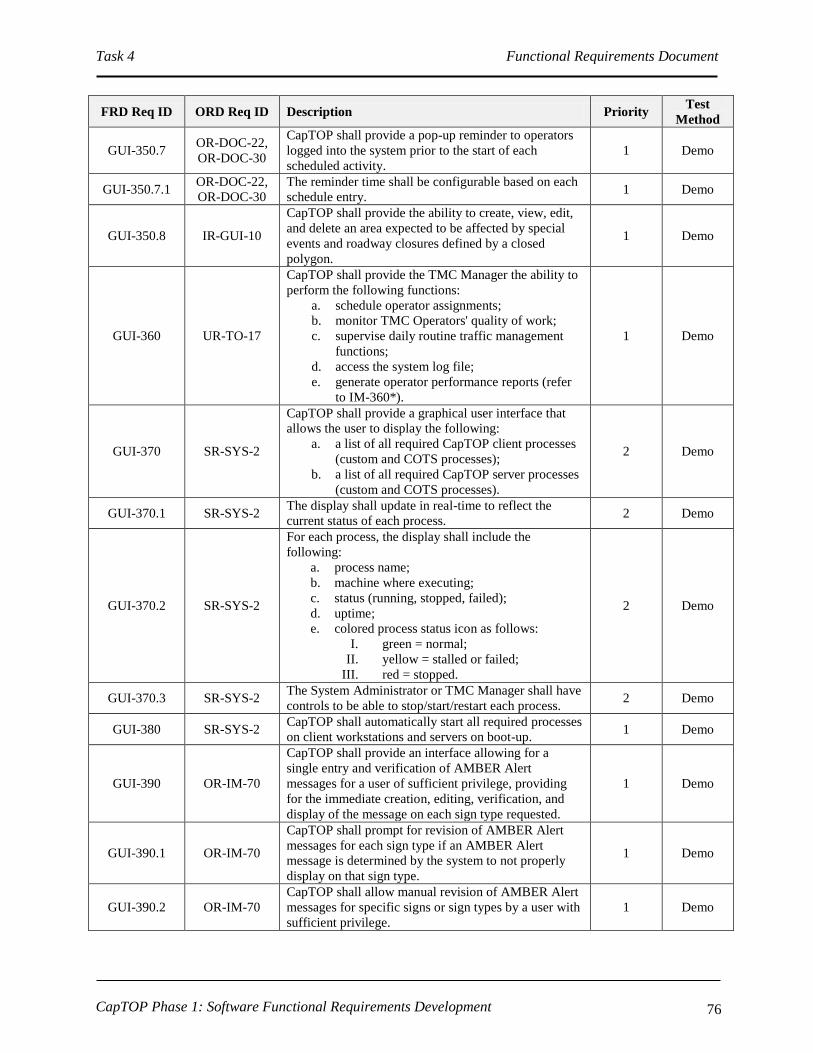
Task 4 Functional Requirements Document
CapTOP Phase 1: Software Functional Requirements Development 76
FRD Req ID ORD Req ID Description Priority Test
Method
GUI-350.7 OR-DOC-22,
OR-DOC-30
CapTOP shall provide a pop-up reminder to operators
logged into the system prior to the start of each
scheduled activity.
1 Demo
GUI-350.7.1 OR-DOC-22,
OR-DOC-30
The reminder time shall be configurable based on each
schedule entry. 1 Demo
GUI-350.8 IR-GUI-10
CapTOP shall provide the ability to create, view, edit,
and delete an area expected to be affected by special
events and roadway closures defined by a closed
polygon.
1 Demo
GUI-360 UR-TO-17
CapTOP shall provide the TMC Manager the ability to
perform the following functions:
a. schedule operator assignments;
b. monitor TMC Operators' quality of work;
c. supervise daily routine traffic management
functions;
d. access the system log file;
e. generate operator performance reports (refer
to IM-360*).
1 Demo
GUI-370 SR-SYS-2
CapTOP shall provide a graphical user interface that
allows the user to display the following:
a. a list of all required CapTOP client processes
(custom and COTS processes);
b. a list of all required CapTOP server processes
(custom and COTS processes).
2 Demo
GUI-370.1 SR-SYS-2 The display shall update in real-time to reflect the
current status of each process. 2 Demo
GUI-370.2 SR-SYS-2
For each process, the display shall include the
following:
a. process name;
b. machine where executing;
c. status (running, stopped, failed);
d. uptime;
e. colored process status icon as follows:
I. green = normal;
II. yellow = stalled or failed;
III. red = stopped.
2 Demo
GUI-370.3 SR-SYS-2 The System Administrator or TMC Manager shall have
controls to be able to stop/start/restart each process. 2 Demo
GUI-380 SR-SYS-2 CapTOP shall automatically start all required processes
on client workstations and servers on boot-up. 1 Demo
GUI-390 OR-IM-70
CapTOP shall provide an interface allowing for a
single entry and verification of AMBER Alert
messages for a user of sufficient privilege, providing
for the immediate creation, editing, verification, and
display of the message on each sign type requested.
1 Demo
GUI-390.1 OR-IM-70
CapTOP shall prompt for revision of AMBER Alert
messages for each sign type if an AMBER Alert
message is determined by the system to not properly
display on that sign type.
1 Demo
GUI-390.2 OR-IM-70
CapTOP shall allow manual revision of AMBER Alert
messages for specific signs or sign types by a user with
sufficient privilege.
1 Demo
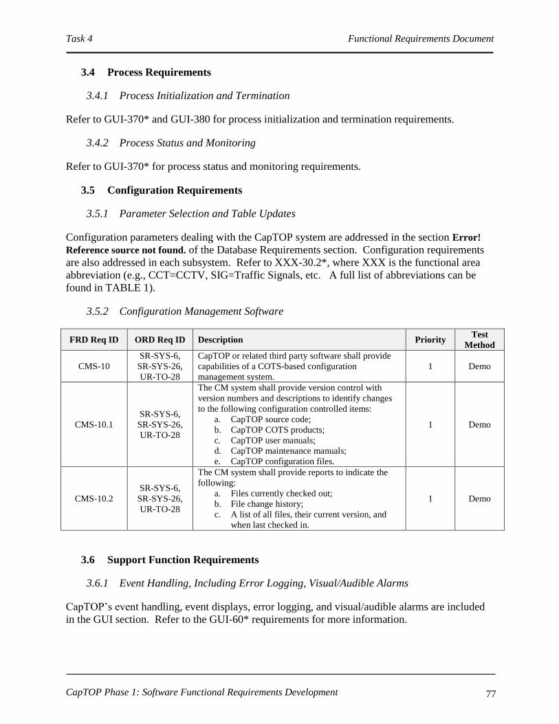
Task 4 Functional Requirements Document
CapTOP Phase 1: Software Functional Requirements Development 77
3.4 Process Requirements
3.4.1 Process Initialization and Termination
Refer to GUI-370* and GUI-380 for process initialization and termination requirements.
3.4.2 Process Status and Monitoring
Refer to GUI-370* for process status and monitoring requirements.
3.5 Configuration Requirements
3.5.1 Parameter Selection and Table Updates
Configuration parameters dealing with the CapTOP system are addressed in the section Error!
Reference source not found. of the Database Requirements section. Configuration requirements
are also addressed in each subsystem. Refer to XXX-30.2*, where XXX is the functional area
abbreviation (e.g., CCT=CCTV, SIG=Traffic Signals, etc. A full list of abbreviations can be
found in TABLE 1).
3.5.2 Configuration Management Software
FRD Req ID ORD Req ID Description Priority Test
Method
CMS-10
SR-SYS-6,
SR-SYS-26,
UR-TO-28
CapTOP or related third party software shall provide
capabilities of a COTS-based configuration
management system.
1 Demo
CMS-10.1
SR-SYS-6,
SR-SYS-26,
UR-TO-28
The CM system shall provide version control with
version numbers and descriptions to identify changes
to the following configuration controlled items:
a. CapTOP source code;
b. CapTOP COTS products;
c. CapTOP user manuals;
d. CapTOP maintenance manuals;
e. CapTOP configuration files.
1 Demo
CMS-10.2
SR-SYS-6,
SR-SYS-26,
UR-TO-28
The CM system shall provide reports to indicate the
following:
a. Files currently checked out;
b. File change history;
c. A list of all files, their current version, and
when last checked in.
1 Demo
3.6 Support Function Requirements
3.6.1 Event Handling, Including Error Logging, Visual/Audible Alarms
CapTOP’s event handling, event displays, error logging, and visual/audible alarms are included
in the GUI section. Refer to the GUI-60* requirements for more information.

Task 4 Functional Requirements Document
CapTOP Phase 1: Software Functional Requirements Development 78
3.6.2 Communication Text Messaging / Alerts
CapTOP’s text messaging and alert requirements are included in the Incident Management
section. Refer to the INM-100* and INM-180* requirements for more information.
3.6.3 Task and Event Scheduler
CapTOP’s task and event scheduler requirements are included in the GUI section. Refer to the
GUI-350* requirements, and also the scheduler requirements within each subsystem, as
applicable.
3.6.4 System Backups
CapTOP’s system backup requirements are included in the System-Level requirements section.
Refer to the SYS-240* and SYS-250* requirements for more information.
Also, refer to the database backup requirements. Refer to section Error! Reference source not
found. for additional information.
3.6.5 Performance Requirements
FRD Req ID ORD Req ID Description Priority Test
Method
PER-10 PR-SYS-1
CapTOP, operating under a nominal load, shall
consume no more than 50% CPU, RAM, network
bandwidth, and disk space on any workstation
averaged over a 24-hour period.
1 Demo
PER-20 PR-SYS-2
CapTOP, operating under a nominal load, shall
consume no more than 50% CPU, RAM, network
bandwidth, and disk space on any server averaged over
a 24-hour period.
1 Demo
PER-30 PR-SYS-3
CapTOP shall be able to recover from workstation
failures by allowing a user to access a backup
workstation and resume the session previously active
on the failed workstation.
2 Demo
PER-40 PR-SYS-4
CapTOP shall be able to effectively recover from
communication server, database server, and
application server failures within 10 seconds by failing
over to hot-backup servers that are kept up to date with
the latest software and database information without
action taken by TMC or other DDOT staff.
2 Demo
PER-50 PR-SYS-5
CapTOP shall provide the ability to allow all
communication devices to be failed over to redundant
servers without action taken by TMC or other DDOT
staff.
2 Demo
PER-60 PR-SYS-6
CapTOP shall be able to recover from a catastrophic
failure using a backup of all CapTOP application,
database, and communication server software and
databases with data loss limited to the period from the
failure to the system restoration.
C Demo

Task 4 Functional Requirements Document
CapTOP Phase 1: Software Functional Requirements Development 79
FRD Req ID ORD Req ID Description Priority Test
Method
PER-70 PR-SYS-7
CapTOP shall be fully operational and functioning 24
hours a day, 365 days a year, with a 99.9% or greater
availability (not including regularly scheduled
maintenance) to minimize downtime.
C Demo/
Analyze
PER-80 OR-SMM-10
CapTOP shall incorporate the following features to
minimize the probability and impact of failures:
a. workstation redundancy;
b. server redundancy;
c. database redundancy;
d. backups of system data;
e. limited function/data access;
f. lockout of functions/data access, subject to
privilege level;
g. information blocking on operator request,
subject to privilege level;
h. sensitive video blocking on operator request,
subject to privilege level.
1 Demo
3.6.6 System Failover
CapTOP’s failover requirements are included in the Performance Requirements section. Refer to
the PER-30 through PER-80 requirements for more information. Also refer to Database Backup
and Failure Requirements (DBF-*) in section Error! Reference source not found..
Also refer to Section Error! Reference source not found. below.
3.6.7 Backup TMC
CapTOP’s requirements for the Backup TMC are included in the System-Level requirements
section. Refer to the SYS-260* requirements for more information.
3.6.8 On-Line Help
CapTOP’s on-line help requirements are included in the GUI section. Refer to the GUI-310*
requirements for additional information.
3.6.9 On-Line Documentation
CapTOP’s on-line help requirements are included in the System-Level requirements section.
Refer to the SYS-230 requirement for additional information.
3.6.10 Traffic Data Analysis and Visualization
FRD Req ID ORD Req ID Description Priority Test
Method
TDA-10 PR-SYS-1
CapTOP shall provide an interface to a future Traffic
Data Server to obtain traffic condition data and to view
graphical displays.
1 Demo

Task 4 Functional Requirements Document
CapTOP Phase 1: Software Functional Requirements Development 80
FRD Req ID ORD Req ID Description Priority Test
Method
TDA-10.1 PR-SYS-1
CapTOP shall interface with the future Traffic Data
Server to obtain data from these sources:
a. permanent count stations;
b. traffic detection stations;
c. SpeedInfo stations;
d. Traffic.com stations;
e. INRIX sensors;
f. WIM stations.
Refer to TDS-70*, PCS-70*, TDC-70*, SPD-70*,
RTC-40*, and CVN-140*.
1, item f
priority 2 Demo
TDA-10.2 PR-SYS-1
CapTOP shall interface with the future Traffic Data
Server to view graphical visualization displays of
traffic data.
1 Demo
3.6.11 Performance Measurement Requirements
CapTOP’s performance measurement requirements are addressed in various sections. Refer to
the following requirements:
SYS-170;
DBR-30*;
DBR-40*;
DBR-50;
DBR-60;
IM-360*;
CCT-410;
TDS-120;
PCS-130;
TDC-120;
SPD-120;
DMS-260;
HAR-250;
SIG-180;
RWI-120.
3.6.12 System Administration Functions
There are many System Administration functions in CapTOP. Following is a summary of the
key requirements:
Account Management: CapTOP’s system administration requirements are included in
the GUI requirements section. Refer to the GUI-330* and GUI-340* requirements for
more information.

Task 4 Functional Requirements Document
CapTOP Phase 1: Software Functional Requirements Development 81
Configuration Management: CapTOP’s configuration management requirements are
included in the Database and GUI requirements section. Refer to the CDB-* and GUI-
200* requirements for more information.
Process Management: Refer to GUI-370* and GUI-380 for process initialization and
termination requirements.
Note: additional System Administration requirements can be found in this document by
performing a “find” and searching for “System Administrator”.
3.7 Subsystem Functional Requirements
3.7.1 Traffic Surveillance Requirements
This section describes the functional requirements needed to perform traffic surveillance.
3.7.1.1 CCTV Requirements
3.7.1.1.1 Accessing the CCTV System
FRD Req ID ORD Req ID Description Priority Test
Method
CCT-10
OR-DOC-1,
OR-DOC-10,
OR-CMM-4
CapTOP shall allow the TMC Operator to access the
CCTV subsystem, subject to operator privilege level. C Demo
CCT-10.1 OR-DOC-10
CapTOP shall allow the TMC Operator to access the
CCTV subsystem, using the following mechanisms:
a. Left clicking on a CCTV camera icon on the
map display;
b. Left clicking on the CCTV subsystem icon off
the CapTOP toolbar;
c. Left clicking on the CCTV subsystem menu
off the CapTOP toolbar.
1 Demo
CCT-10.2 OR-SMM-5,
OR-DOC-11
CapTOP shall provide role-based privileges to control
access to the following, subject to the user’s privilege
level:
a. CCTV events and alarms;
b. Live and recorded video;
c. Camera controls (refer to CCT-130);
d. Editing of CCTV tour schedule;
e. Camera status (refer to CCT-40);
f. Override control if a camera is locked;
g. CCTV maintenance/diagnostic interface.
C Demo
CCT-20 IR-GUI-10 CapTOP shall display all camera icons on a separate
layer on the map-based display. 1 Demo
CCT-20.1 IR-GUI-12 CapTOP shall allow the TMC Operator to turn on and
off the CCTV layer on the map display. 1 Demo
CCT-20.2 IR-GUI-11
CapTOP shall allow the TMC Operator to left click a
camera icon and perform the following with no more
than 2 additional clicks:
a. View the video locally on the desktop;
b. Invoke the camera control window (refer to
1 Demo

Task 4 Functional Requirements Document
CapTOP Phase 1: Software Functional Requirements Development 82
CCT-130);
c. Route video to a video wall monitor;
d. Invoke the camera status window (refer to
CCT-50);
e. Invoke the camera routing window.
CCT-20.3 IR-GUI-12 The icons used for the CCTV icon layer shall be
unique from icons used in other layers. 1 Demo
CCT-30 IR-GUI-10
CapTOP shall provide the ability for the System
Administrator to add, delete, and modify CCTV
devices from the CapTOP map display (also refer to
GUI-200*).
C Demo
CCT-30.1 IR-GUI-10
CapTOP shall allow the System Administrator to point
and click on a location on the map display to add a
new CCTV icon using a pop-up menu.
1 Demo
CCT-30.2 IR-GUI-10
When a CCTV device icon is added, CapTOP shall
prompt the System Administrator with a window to
enter all configuration data required to integrate the
device.
1 Demo
CCT-30.2.1
IR-GUI-10,
OR-TDCA-20,
OR-TDCA-21
CapTOP shall allow the following configuration data
to be entered for each CCTV device to enable the
device to become operational in the system, with basic
information required during entry into the system:
a. Controller ID (Basic);
b. Description;
c. Location Information;
I. Location Description;
II. Street Address;
III. Road Name;
IV. Road Direction;
V. Exit Number;
VI. Milepost;
VII. Closest Intersection/Interchange.
d. Online-Offline Mode (Basic) ( static – set by
System Administrator or Maintenance
Technician);
e. Encoding Type (Basic) (MPEG-2, MPEG-4,
H.264);
f. Communication Type (Basic) (IP, Encoded,
Video Switcher);
g. Video Switcher Input No. (Basic, if
applicable);
h. Multidrop Information (Basic, if applicable);
I. Drop Address (Basic, if applicable);
II. Channel ID (Basic, if applicable);
III. Port Name (Basic, if applicable).
i. IP Information (Basic, if applicable);
I. IP Address (Basic, if applicable);
II. Port Number (Basic, if applicable).
j. Serial Information (Basic, if applicable);
I. Baud Rate (Basic, if applicable);
II. No. Data Bits (Basic, if applicable);
1 Demo
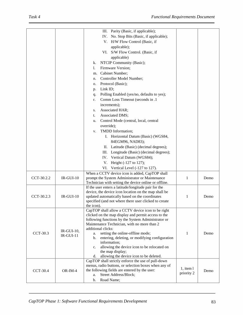
Task 4 Functional Requirements Document
CapTOP Phase 1: Software Functional Requirements Development 83
III. Parity (Basic, if applicable);
IV. No. Stop Bits (Basic, if applicable);
V. H/W Flow Control (Basic, if
applicable);
VI. S/W Flow Control. (Basic, if
applicable)
k. NTCIP Community (Basic);
l. Firmware Version;
m. Cabinet Number;
n. Controller Model Number;
o. Protocol (Basic);
p. Link ID;
q. Polling Enabled (yes/no, defaults to yes);
r. Comm Loss Timeout (seconds in .1
increments);
s. Associated HAR;
t. Associated DMS;
u. Control Mode (central, local, central
override);
v. TMDD Information;
I. Horizontal Datum (Basic) (WGS84,
84EGM96, NAD83);
II. Latitude (Basic) (decimal degrees);
III. Longitude (Basic) (decimal degrees);
IV. Vertical Datum (WGS84);
V. Height (-127 to 127);
VI. Vertical Level (-127 to 127).
CCT-30.2.2 IR-GUI-10
When a CCTV device icon is added, CapTOP shall
prompt the System Administrator or Maintenance
Technician with setting the device online or offline.
1 Demo
CCT-30.2.3 IR-GUI-10
If the user enters a latitude/longitude pair for the
device, the device icon location on the map shall be
updated automatically based on the coordinates
specified (and not where there user clicked to create
the icon).
1 Demo
CCT-30.3 IR-GUI-10,
IR-GUI-11
CapTOP shall allow a CCTV device icon to be right
clicked on the map display and permit access to the
following functions by the System Administrator or
Maintenance Technician, with no more than 2
additional clicks:
a. setting the online-offline mode;
b. entering, deleting, or modifying configuration
information;
c. allowing the device icon to be relocated on
the map display;
d. allowing the device icon to be deleted.
1 Demo
CCT-30.4 OR-IM-4
CapTOP shall strictly enforce the use of pull-down
menus, radio buttons, or selection boxes when any of
the following fields are entered by the user:
a. Street Address/Block;
b. Road Name;
1, item l
priority 2 Demo

Task 4 Functional Requirements Document
CapTOP Phase 1: Software Functional Requirements Development 84
c. Road Direction;
d. Exit Number;
e. Milepost;
f. Intersection/Interchange;
g. Online-Offline Mode (online/offline);
h. Communication Type (dialup serial, network
serial, IP);
i. Protocol;
j. Link ID;
k. Polling Enabled (yes/no, defaults to yes);
l. Associated HAR;
m. Associated DMS;
n. Control Mode (central, local, central
override);
o. Encoding Type (MPEG-2, MPEG-4, H.264);
p. Communication Type (IP, Encoded, Video
Switcher).
CCT-30.4.1 OR-IM-4 CapTOP shall restrict the use of free-form text entry
on the fields identified above. 1 Demo
CCT-30.4.2 OR-IM-4
CapTOP shall allow the user to type the 1st 3
characters in each field and the system will provide a
filtered list of selections for that field that begin with
the 1st 3 characters typed by the user.
2 Demo
CCT-30.4.3 OR-IM-4
CapTOP shall allow the user to select “Other” and
enter in free form text when a desired entry cannot be
found in the list.
1 Demo
3.7.1.1.2 Monitoring Camera Status
FRD Req ID ORD Req ID Description Priority Test
Method
CCT-40 OR-DOC-10,
IR-GUI-16
CapTOP shall allow the TMC Operator to retrieve and
display the following operational status of any camera,
subject to operator privilege level:
a. Controller ID;
b. Online-offline mode ( static – set by System
Administrator or Maintenance Technician);
c. Communication status (OK, failed);
d. Controller status (OK, failed);
e. Control mode (central, local, central
override);
f. Lock status (username if locked);
g. Display blocked to public (yes/no);
h. Where displayed;
i. Auto-iris status;
j. Auto-focus status;
k. Current title;
l. Last contact (date/time);
m. Last communication status change
(date/time);
n. Alarm status.
C Demo
CCT-40.1 OR-DOC-1 CapTOP shall use data from the following sources to C Demo

Task 4 Functional Requirements Document
CapTOP Phase 1: Software Functional Requirements Development 85
FRD Req ID ORD Req ID Description Priority Test
Method
determine operational status:
a. data reported from the cameras;
b. data gained by CapTOP in attempts to
communicate with the cameras;
c. online/offline information entered manually
by authorized CapTOP users.
CCT-50
SR-SYS-2,
IR-GUI-29,
IR-GUI-36,
IR-GUI-26
CapTOP shall allow users to simultaneously view
camera status, which is refreshed automatically by the
system based on the polling interval, using the
following methods:
a. Color coded icons on the map display;
b. Via the camera status window which lists all
cameras, the Controller ID, location, online-
offline mode, and controller status.
C Demo
CCT-50.1 IR-GUI-28,
IR-GUI-26
CapTOP shall use the following colors for device icon
states:
a. Green = online;
b. Red = device failure;
c. Yellow = communication failure;
d. Gray = offline;
e. Operator lock = black;
f. Partial operation or recent failure = brown.
C Demo
CCT-50.1.1 IR-GUI-28,
IR-GUI-26
CapTOP shall use the following rules for device icon
states:
a. If the device is online but in communication
failure, the device icon color should be that of
a device with a communication failure;
b. In order for the device icon to be green, the
device must be both online and have OK
communication.
C Demo
CCT-50.2 IR-GUI-29
The refresh rate for the status of the icons and for the
data in the status window shall be configurable and
based upon the polling rate.
1 Demo
CCT-50.3 IR-GUI-31
CapTOP shall allow the user to obtain summary status
information (refer to CCT-40 for the list of fields) by
hovering over a CCTV camera icon.
1 Demo
CCT-50.4 IR-GUI-29
CapTOP shall allow the user to select on any camera in
the camera status window (refer to CCT-50 item b)
and view all details (full status, configuration
information, and camera controls) pertaining to that
camera.
1 Demo
CCT-60
SR-SYS-2, IR-
GUI-29, IR-
GUI-31, IR-
GUI-32
CapTOP shall provide a menu option to search for a
CCTV camera by the following methods:
a. by device ID;
b. IP address of encoder;
c. IP address/drop address/channel ID of
camera;
d. by street name;
e. by geographical address;
f. by intersection/interchange.
C Demo
CCT-60.1 SR-SYS-2, IR-
GUI-29
CapTOP shall allow the TMC Operator to search for
CCTV cameras using a rubber-band style box on the
map display to search an area.
C Demo
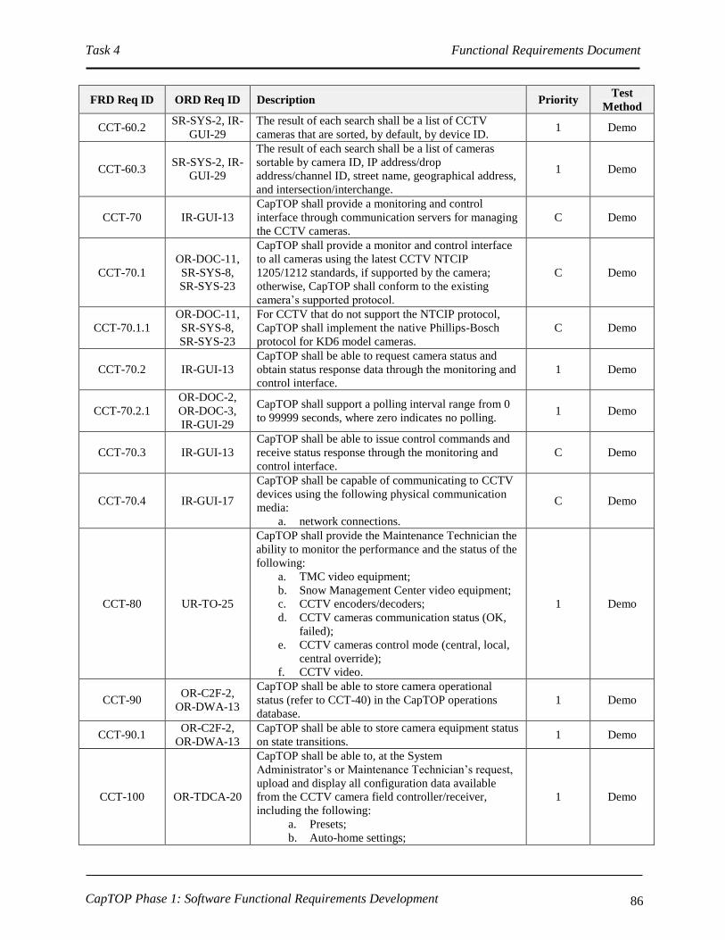
Task 4 Functional Requirements Document
CapTOP Phase 1: Software Functional Requirements Development 86
FRD Req ID ORD Req ID Description Priority Test
Method
CCT-60.2 SR-SYS-2, IR-
GUI-29
The result of each search shall be a list of CCTV
cameras that are sorted, by default, by device ID. 1 Demo
CCT-60.3 SR-SYS-2, IR-
GUI-29
The result of each search shall be a list of cameras
sortable by camera ID, IP address/drop
address/channel ID, street name, geographical address,
and intersection/interchange.
1 Demo
CCT-70 IR-GUI-13
CapTOP shall provide a monitoring and control
interface through communication servers for managing
the CCTV cameras.
C Demo
CCT-70.1
OR-DOC-11,
SR-SYS-8,
SR-SYS-23
CapTOP shall provide a monitor and control interface
to all cameras using the latest CCTV NTCIP
1205/1212 standards, if supported by the camera;
otherwise, CapTOP shall conform to the existing
camera’s supported protocol.
C Demo
CCT-70.1.1
OR-DOC-11,
SR-SYS-8,
SR-SYS-23
For CCTV that do not support the NTCIP protocol,
CapTOP shall implement the native Phillips-Bosch
protocol for KD6 model cameras.
C Demo
CCT-70.2 IR-GUI-13
CapTOP shall be able to request camera status and
obtain status response data through the monitoring and
control interface.
1 Demo
CCT-70.2.1
OR-DOC-2,
OR-DOC-3,
IR-GUI-29
CapTOP shall support a polling interval range from 0
to 99999 seconds, where zero indicates no polling. 1 Demo
CCT-70.3 IR-GUI-13
CapTOP shall be able to issue control commands and
receive status response through the monitoring and
control interface.
C Demo
CCT-70.4 IR-GUI-17
CapTOP shall be capable of communicating to CCTV
devices using the following physical communication
media:
a. network connections.
C Demo
CCT-80 UR-TO-25
CapTOP shall provide the Maintenance Technician the
ability to monitor the performance and the status of the
following:
a. TMC video equipment;
b. Snow Management Center video equipment;
c. CCTV encoders/decoders;
d. CCTV cameras communication status (OK,
failed);
e. CCTV cameras control mode (central, local,
central override);
f. CCTV video.
1 Demo
CCT-90 OR-C2F-2,
OR-DWA-13
CapTOP shall be able to store camera operational
status (refer to CCT-40) in the CapTOP operations
database.
1 Demo
CCT-90.1 OR-C2F-2,
OR-DWA-13
CapTOP shall be able to store camera equipment status
on state transitions. 1 Demo
CCT-100 OR-TDCA-20
CapTOP shall be able to, at the System
Administrator’s or Maintenance Technician’s request,
upload and display all configuration data available
from the CCTV camera field controller/receiver,
including the following:
a. Presets;
b. Auto-home settings;
1 Demo

Task 4 Functional Requirements Document
CapTOP Phase 1: Software Functional Requirements Development 87
FRD Req ID ORD Req ID Description Priority Test
Method
c. Focus settings;
d. Iris settings;
e. Pan/tilt/zoom speeds;
f. Titles;
g. Alarm configurations;
h. Sector configurations;
i. Video logos;
a. Compass settings.
CCT-110 OR-TDCA-21
CapTOP shall be able to, at the System
Administrator’s or Maintenance Technician’s request,
upload and store all camera field controller/receiver
configuration data in the CapTOP central system
device configuration database for CCTV cameras.
1 Demo
CCT-120 OR-TDCA-22
CapTOP shall be able to, at the System
Administrator’s or Maintenance Technician’s request,
download all camera configuration data from the
CapTOP central system device configuration database
to the CCTV camera field controller/receiver.
1 Demo

Task 4 Functional Requirements Document
CapTOP Phase 1: Software Functional Requirements Development 88
3.7.1.1.3 CCTV Control Commands
FRD Req ID ORD Req ID Description Priority Test
Method
CCT-130 OR-DOC-11,
SR-SYS-23
CapTOP shall allow the TMC Operator to issue the
following commands to any camera, using a GUI
control window, subject to operator privilege level:
a. Pan left;
b. Pan right;
c. Tilt up;
d. Tilt down;
e. Pan/tilt diagonally upper right;
f. Pan/tilt diagonally lower right;
g. Pan/tilt diagonally upper left;
h. Pan/tilt diagonally lower left;
i. Zoom in;
j. Zoom out;
k. Open iris;
l. Close iris;
m. Enable auto iris;
n. Disable auto iris;
o. Focus near;
p. Focus far;
q. Enable auto focus;
r. Disable auto focus;
s. Increase pan speed;
t. Decrease pan speed;
u. Increase tilt speed;
v. Decrease tilt speed;
w. Go to preset;
x. Delete preset;
y. Enable auxiliary function;
z. Disable auxiliary function;
aa. Power reset.
C, items
m – aa
priority 1
Demo
CCT-130.1
OR-DOC-11,
SR-SYS-8,
SR-SYS-23
CapTOP shall notify the TMC Operator of any failed
command transmissions. 1 Demo
CCT-130.2 OR-DOC-11
SR-SYS-14
CapTOP shall access camera control functions via an
intuitive, Windows-based GUI. C Inspect
CCT-140 OR-DOC-11,
SR-SYS-23
CapTOP shall support a programmable macro
capability similar to Microsoft Word or Excel macros. 3 Demo
CCT-140.1 OR-DOC-11,
SR-SYS-23
The TMC Operator shall be able to configure a
minimum of 100 macros in the system. 3 Demo
CCT-140.2 OR-DOC-11,
SR-SYS-23
A macro shall be able to be triggered from any (all are
required, none are optional) of the following stimuli:
a. RS-232C input via any COM port;
b. TCP/IP input;
c. At user login;
d. At the occurrence of a regular scheduled
event (e.g., date and time), which is non-
recurring;
e. At the occurrence of a recurring scheduled
event (e.g., every Monday at 6:30 AM);
3 Demo

Task 4 Functional Requirements Document
CapTOP Phase 1: Software Functional Requirements Development 89
FRD Req ID ORD Req ID Description Priority Test
Method
CCT-140.3 OR-DOC-11,
SR-SYS-23
Each programmable macro shall allow the TMC
Operator to perform any of the following:
a. View a camera at its current position;
b. View a camera at a defined preset;
c. View a video tour;
d. View the message on a DMS/PDMS;
e. Activate the incident management system;
f. Run an external application;
g. Alert the TMC Operator using a pop-up;
h. Alert the TMC Operator using an audible;
i. Activate a dry-contact;
j. Load a map file.
3 Demo
CCT-140.4 OR-DOC-11,
SR-SYS-23
The TMC Operator shall be able to configure the order
of executed steps that comprise a macro, through an
intuitive CapTOP GUI.
3 Demo
CCT-140.5 OR-DOC-11,
SR-SYS-23
CapTOP shall have the ability to enable/disable
macros. 3 Demo
CCT-150 SR-SYS-2,
IR-GUI-19
CapTOP shall allow two or more different users to
simultaneously control two or more different cameras
at the same time.
1 Demo
CCT-150.1 SR-SYS-2,
IR-GUI-29
CapTOP shall take no longer than 20 seconds after
command transmission to update the status of the
CCTV camera within the system.
1 Demo
CCT-160 SR-SYS-2,
SR-SYS-12
CapTOP shall allow users, with proper privileges, to
monitor and control any camera, from any CapTOP
workstation.
1 Demo
CCT-170 SR-SYS-2,
OR-SMM-5
CapTOP shall provide a software locking mechanism
to prevent 2 or more operators from simultaneously
controlling the same camera.
C Demo
CCT-170.1 SR-SYS-2,
OR-SMM-5
CapTOP shall allow all TMC operators, subject to
privilege level, to only view the camera status and
video (not control), if the camera is locked.
C Demo
CCT-170.2 SR-SYS-2,
OR-SMM-5
CapTOP shall provide a notification to the user when
he attempts to control a camera currently locked by
another user.
1 Demo
CCT-170.2.1 SR-SYS-2,
OR-SMM-5
The notification shall provide the ID of the camera and
the user name that has the camera locked. 1 Demo
CCT-170.3 OR-SMM-5
CapTOP shall allow a camera icon to be left clicked on
the map display by the TMC Operator, subject to
privilege level, and enable locking with no more than 2
clicks.
1 Demo
CCT-170.4 OR-SMM-5 CapTOP shall remove camera locks set by an
individual user when that user logs out of the system. 1 Demo
CCT-170.5 OR-SMM-5 CapTOP shall remove camera locks after a
configurable time period has elapsed. 1 Demo
CCT-180 SR-SYS-2,
OR-SMM-5
CapTOP shall provide the ability for a user with
override privileges to unlock cameras that are locked. 1 Demo
CCT-180.1 OR-SMM-5 CapTOP shall issue an alert to a user when a camera
that the user locked has been overridden. 1 Demo
3.7.1.1.4 CCTV Tours
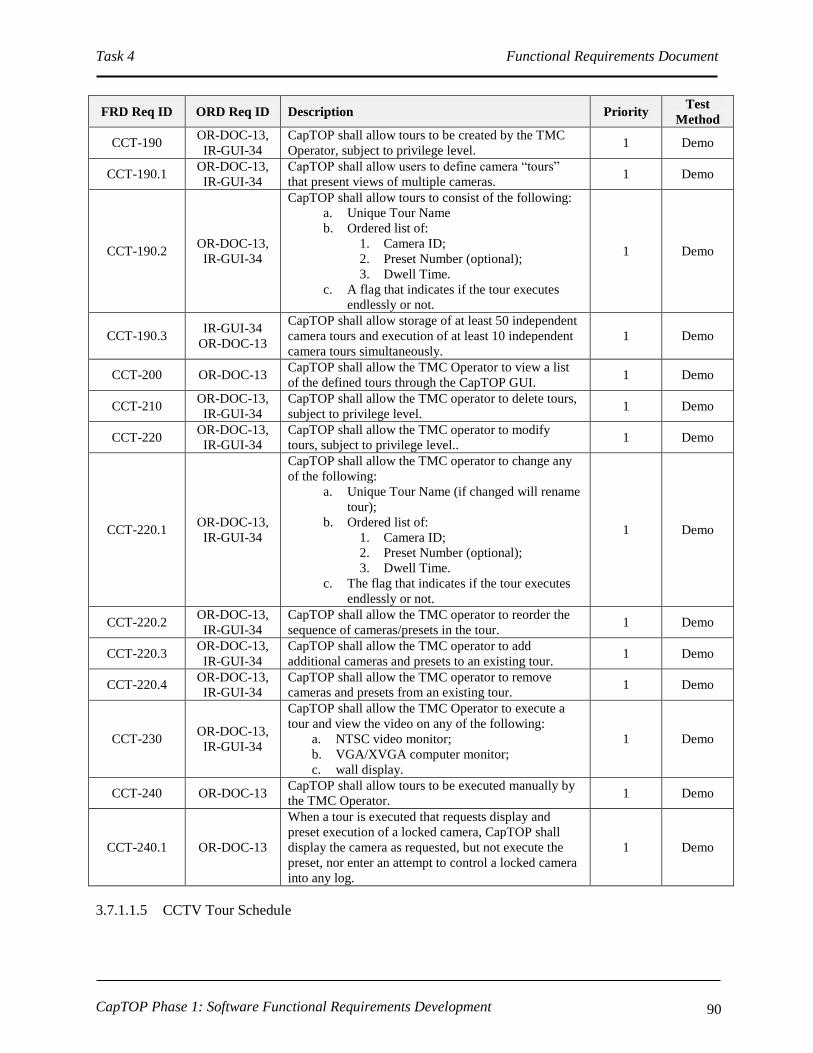
Task 4 Functional Requirements Document
CapTOP Phase 1: Software Functional Requirements Development 90
FRD Req ID ORD Req ID Description Priority Test
Method
CCT-190 OR-DOC-13,
IR-GUI-34
CapTOP shall allow tours to be created by the TMC
Operator, subject to privilege level. 1 Demo
CCT-190.1 OR-DOC-13,
IR-GUI-34
CapTOP shall allow users to define camera “tours”
that present views of multiple cameras. 1 Demo
CCT-190.2 OR-DOC-13,
IR-GUI-34
CapTOP shall allow tours to consist of the following:
a. Unique Tour Name
b. Ordered list of:
1. Camera ID;
2. Preset Number (optional);
3. Dwell Time.
c. A flag that indicates if the tour executes
endlessly or not.
1 Demo
CCT-190.3 IR-GUI-34
OR-DOC-13
CapTOP shall allow storage of at least 50 independent
camera tours and execution of at least 10 independent
camera tours simultaneously.
1 Demo
CCT-200 OR-DOC-13 CapTOP shall allow the TMC Operator to view a list
of the defined tours through the CapTOP GUI. 1 Demo
CCT-210 OR-DOC-13,
IR-GUI-34
CapTOP shall allow the TMC operator to delete tours,
subject to privilege level. 1 Demo
CCT-220 OR-DOC-13,
IR-GUI-34
CapTOP shall allow the TMC operator to modify
tours, subject to privilege level.. 1 Demo
CCT-220.1 OR-DOC-13,
IR-GUI-34
CapTOP shall allow the TMC operator to change any
of the following:
a. Unique Tour Name (if changed will rename
tour);
b. Ordered list of:
1. Camera ID;
2. Preset Number (optional);
3. Dwell Time.
c. The flag that indicates if the tour executes
endlessly or not.
1 Demo
CCT-220.2 OR-DOC-13,
IR-GUI-34
CapTOP shall allow the TMC operator to reorder the
sequence of cameras/presets in the tour. 1 Demo
CCT-220.3 OR-DOC-13,
IR-GUI-34
CapTOP shall allow the TMC operator to add
additional cameras and presets to an existing tour. 1 Demo
CCT-220.4 OR-DOC-13,
IR-GUI-34
CapTOP shall allow the TMC operator to remove
cameras and presets from an existing tour. 1 Demo
CCT-230 OR-DOC-13,
IR-GUI-34
CapTOP shall allow the TMC Operator to execute a
tour and view the video on any of the following:
a. NTSC video monitor;
b. VGA/XVGA computer monitor;
c. wall display.
1 Demo
CCT-240 OR-DOC-13 CapTOP shall allow tours to be executed manually by
the TMC Operator. 1 Demo
CCT-240.1 OR-DOC-13
When a tour is executed that requests display and
preset execution of a locked camera, CapTOP shall
display the camera as requested, but not execute the
preset, nor enter an attempt to control a locked camera
into any log.
1 Demo
3.7.1.1.5 CCTV Tour Schedule

Task 4 Functional Requirements Document
CapTOP Phase 1: Software Functional Requirements Development 91
FRD Req ID ORD Req ID Description Priority Test
Method
CCT-250 OR-DOC-22,
OR-DOC-30
CapTOP shall be able to define and schedule camera
tours to be executed automatically according to a
schedule using a schedule editor.
1 Demo
CCT-250.1 OR-DOC-14
CapTOP shall be able to define and schedule camera
tours to be executed to monitor the following traffic
operations:
a. Morning rush hour;
b. Afternoon rush hour;
c. Special events;
d. Any other time desired.
1 Demo
CCT-250.2 OR-DOC-22,
OR-DOC-30
The CapTOP schedule capability shall permit time of
day recurring and non-recurring entries for camera
tours.
1 Demo
CCT-250.3 OR-DOC-22,
OR-DOC-30
The schedule shall permit a non-recurring, one-time
only camera tour to be executed, where the user
specifies a schedule name, camera tour name, reminder
date/time, start date/time and end date/time.
1 Demo
CCT-250.4 OR-DOC-22,
OR-DOC-30
CapTOP shall provide a recurring schedule capability
and permit any of the following recurring entry types:
a. Weekdays – Monday through Friday;
b. Weekends – Saturday and Sunday only;
c. All Days – Monday through Sunday;
d. One day or any combination of days per
week;
e. One day or any combination of days per
month.
1 Demo
CCT-250.4.1 OR-DOC-22,
OR-DOC-30
CapTOP shall allow recurring schedule entries to be
created for a camera tour, where the user specifies a
schedule name, camera tour name, recurring entry
type, reminder date/time, start date/time and end
date/time (optional).
1 Demo
CCT-250.4.2 OR-DOC-22,
OR-DOC-30
CapTOP shall permit an optional end date to be
specified for all recurring schedule entries. 1 Demo
CCT-250.4.2.1 OR-DOC-22,
OR-DOC-30
CapTOP shall implement the recurring scheduling
indefinitely if no end date is specified. 1 Demo
CCT-250.4.3 OR-DOC-22,
OR-DOC-30
CapTOP shall allow a Holiday schedule to be specified
for the CapTOP system. 1 Demo
CCT-250.4.3.1 OR-DOC-22,
OR-DOC-30
CapTOP shall allow the user to indicate whether each
Holiday is treated as an exception to the recurring
schedule.
1 Demo
CCT-250.4.3.2 OR-DOC-22,
OR-DOC-30
CapTOP shall allow the user to specify each Holiday
exception to be treated as either a Weekend or
Weekday whenever encountered.
1 Demo
CCT-260 OR-DOC-22,
OR-DOC-30
CapTOP shall allow the TMC Operator to edit and
delete scheduled entries for camera tours. 1 Demo
3.7.1.1.6 CCTV Presets
FRD Req ID ORD Req ID Description Priority Test
Method
CCT-270 OR-DOC-12 CapTOP shall allow presets to be created by the TMC
Operator, subject to privilege level. C Demo
CCT-270.1 OR-DOC-12 CapTOP shall be able to exchange preset data between C Demo

Task 4 Functional Requirements Document
CapTOP Phase 1: Software Functional Requirements Development 92
FRD Req ID ORD Req ID Description Priority Test
Method
CapTOP storage and CCTV controller storage,
identifying discrepancies and allowing users to select
which preset data to retain, and making the preset data
sets consistent.
CCT-280 OR-DOC-12 CapTOP shall allow users to define a minimum of 8
camera presets per camera. 1 Demo
CCTV290 OR-DOC-12
CapTOP shall allow each preset to be uniquely named
and to store the camera pan, tilt, zoom, focus and iris
settings with each preset.
C Demo
CCT-300 OR-DOC-12 CapTOP shall allow the TMC operator to delete
presets. C Demo
CCT-310 OR-DOC-12 CapTOP shall allow the TMC operator to rename
presets. C Demo
CCT-320 OR-DOC-12 CapTOP shall allow the TMC Operator view the
presets defined for any camera. C Demo
CCT-330 OR-DOC-12 CapTOP shall allow the TMC Operator to go to any
preset defined for any camera. C Demo
CCT-330.1 OR-DOC-12
CapTOP shall ensure that presets are accurately
recalled and provide the resolution to allow return to
predefined positions within 1-degree of the stored
pan/tilt position.
1 Test
CCT-330.2 OR-DOC-12 CapTOP shall display the title of an activated preset
within the video image, at user option. 2 Demo
3.7.1.1.7 CCTV Video Routing
FRD Req ID ORD Req ID Description Priority Test
Method
CCT-340 OR-DOC-11
CapTOP shall allow video routing commands to be
executed by the TMC Operator, subject to privilege
level.
C Demo
CCT-340.1 OR-DOC-11
CapTOP shall allow video routing commands to be
executed by having the CCTV server communicate
with the existing video switcher.
C Demo
CCT-340.1.1 OR-DOC-11
CapTOP shall provide a video routing interface to
DDOT’s existing Bosch Allegiant video switcher using
the existing video switcher’s native protocol.
C Demo
CCT-340.2 OR-DOC-11
CapTOP shall allow video routing commands to be
executed by having the CCTV server communicate
with the future hardware MPEG-2/MPEG-4/H.264
decoders to change the multicast IP address listened to
by the decoder.
1 Demo
CCT-350 OR-DOC-11,
SR-SYS-23
CapTOP shall allow the TMC operator to be able to
route any video input to any video output, except
another operator’s workstation.
C Demo
CCT-350.1 OR-DOC-11,
SR-SYS-23 CapTOP shall provide a list of all the video inputs. C Demo
CCT-350.2 OR-DOC-11,
SR-SYS-23
CapTOP shall provide a graphical representation,
using selectable icons, embedded selectable graphics
or other methods to graphically depict the video wall,
and all other available outputs cabinet of receiving
video.
C Demo
CCT-350.3 OR-DOC-10, CapTOP shall provide a drag-and-drop capability to 1 Demo

Task 4 Functional Requirements Document
CapTOP Phase 1: Software Functional Requirements Development 93
FRD Req ID ORD Req ID Description Priority Test
Method
SR-SYS-23 route any video input to any video output.
CCT-350.4 OR-DOC-11,
SR-SYS-23
CapTOP shall support the following video inputs:
a. NTSC cameras;
b. IP cameras encoded as MPEG-2, MPEG-4 or
H.264;
c. DVRs;
d. VCRs;
e. Camera tours.
C Demo
CCT-350.5 OR-DOC-11,
SR-SYS-23
CapTOP shall support the following video outputs:
a. NTSC monitors;
b. VGA/XVGA monitors;
c. DVRs;
d. VCRs.
C Demo
CCT-350.6 OR-DOC-11,
OR-IM-13
CapTOP shall allow the TMC Operator to click on a
camera icon off the map display and view video on any
NTSC monitor.
C Demo
CCT-350.7 OR-DOC-11,
OR-IM-13
CapTOP shall allow the TMC Operator to click on a
camera icon off the map display and view video on the
local VGA/XVGA computer monitor using software
decoding technology for MPEG-2/MPEG-4/H.264
video streams.
C Demo
CCT-350.8 OR-DOC-11,
OR-IM-13
CapTOP shall allow the TMC Operator to select a
camera from a pull-down list and view video on any
NTSC monitor.
C Demo
CCT-350.9 OR-DOC-11,
OR-IM-13
CapTOP shall allow the TMC Operator to select a
camera from a pull-down list and view video on the
local VGA/XVGA computer monitor using software
decoding technology for MPEG-2/MPEG-4/H.264
video streams.
C Demo
CCT-350.10 OR-DOC-11,
OR-IM-13
CapTOP shall allow the TMC Operator to select a
“video not available” input for any camera to block
video that DDOT may, from time-to-time, deem
sensitive.
C Demo
CCT-350.11 OR-DOC-11,
SR-SYS-23
CapTOP shall allow the System Administrator to add
inputs and outputs to the CCTV system without
changing the code.
C Demo
CCT-360 OR-DOC-11,
OR-IM-13
CapTOP shall provide an interface to receive and
display mobile video images from wireless portable
CCTV cameras used by ROP operators.
2 Demo
CCT-370 OR-RTC-13,
OR-RTC-14
CapTOP shall be able to route video to share with
external agencies. 2 Demo
CCT-380 OR-RTC-13,
OR-RTC-14
CapTOP shall be able to stream video to the web to
share with Internet users. 2 Demo
3.7.1.1.8 CCTV Reports
FRD Req ID ORD Req ID Description Priority Test
Method
CCT-390 OR-DOC-22,
OR-DOC-30
CapTOP shall allow the TMC Operator to produce a
report of all scheduled entries for an individual camera
or all cameras.
1 Demo
CCT-390.1 OR-DOC-22, The report shall list all schedule entries, and shall 2 Demo

Task 4 Functional Requirements Document
CapTOP Phase 1: Software Functional Requirements Development 94
FRD Req ID ORD Req ID Description Priority Test
Method
OR-DOC-30 contain the following:
a. Schedule name;
b. Tour name;
c. Message ID;
d. Recurrent entry type (optional);
e. State Date/Time;
f. End Date/Time (optional).
CCT-400
SR-SYS-22,
SR-SYS-36,
OR-DOC-4,
IR-GUI-8
CapTOP shall be able to automatically generate real-
time tabular reports that show the real-time operational
status of all cameras.
2 Demo
CCT-400.1
SR-SYS-22,
SR-SYS-36,
OR-DOC-4,
IR-GUI-8
CapTOP shall provide the following information in the
camera status report:
a. Camera ID;
b. Location;
c. Online-offline mode;
d. Locked or unlocked status with user name;
e. Control mode (central, local, central
override);
f. Communication status (OK, failed);
g. Alarm status.
2 Demo
CCT-410 OR-DWA-7
CapTOP shall be able to produce the following
performance reports for evaluating the performance of
cameras, using data in the CapTOP operations and
archived databases:
a. Number of times a camera transitioned from
online to offline over a specified time period;
b. Number of times a camera transitioned from
no device failure to device failure over a
specified time period;
c. Number of times a camera transitioned from
no communication failure to communication
failure over a specified time period.
2 Demo
CCT-420
SR-SYS-22,
SR-SYS-36,
OR-DOC-4,
IR-GUI-8
CapTOP shall be able to display and print the
following reports:
a. For a user entered CCTV ID, provide a
camera history report, consisting of the CCTV
ID, date/time last controlled, and username
who controlled the camera.
b. For a user entered user ID, provide a message
history report, consisting of the User ID,
CCTV ID, and date/time last commanded.
c. For a user entered CCTV ID, provide a full
device configuration report;
d. For a user specified time-interval, provide a
camera history report, consisting of the CCTV
ID, date/time last controlled, and username
who controlled the camera;
e. For a user specified CCTV ID and time
interval, provide a camera history report
consisting of the control action, date/time of
control, and username who controlled the
camera
f. An ad-hoc report where the user can query
2 Demo

Task 4 Functional Requirements Document
CapTOP Phase 1: Software Functional Requirements Development 95
FRD Req ID ORD Req ID Description Priority Test
Method
any data stored in CCTV related databases.
CCT-420.1
SR-SYS-22,
SR-SYS-36,
OR-DOC-4,
IR-GUI-8
CapTOP shall support the following capabilities for all
reports:
a. be able to display all reports in a tabular
format;
b. be able to display graphical reports in a
Microsoft Excel-like 2-dimensional or 3-
dimensional format.
c. be able to print all reports in landscape or
portrait modes;
d. include the report name and date generated on
the header;
e. support a template capability for each report,
allowing the user to select which fields to
display;
f. include the page number on the footer.
a. 2
b. 2
c. 2
d. 2
e. 2
f. 2
Demo
3.7.1.1.9 CCTV Application Interfaces
FRD Req ID ORD Req ID Description Priority Test
Method
CCT-430 OR-IM-1
The CapTOP software shall support an interface to a
future incident detection system (a separate system
deployed by others) via a TCP interface.
2 Demo
CCT-430.1 OR-IM-1
CapTOP shall have the ability to trigger a macro to be
executed based on the receipt of an incident alarm
from the incident detection system.
2 Demo
CCT-430.1.1 OR-IM-1
CapTOP shall be able to support the following
scenario:
a. Receive an external stimulus from the future
incident detection system with a Camera-ID
or location provided in the message;
b. Execute a macro based on an alarm from the
incident detection interface that will perform
the following:
i. select a camera;
ii. display the video on the TMC
Operator’s workstation;
iii. move the camera to a predefined
preset;
iv. route the video to a designated output.
2 Demo
3.7.1.1.10 CCTV Video Recording
FRD Req ID ORD Req ID Description Priority Test
Method
CCT-440 OR-DWA-13 CapTOP shall provide the ability to store traffic video. 1 Demo
CCT-440.1 OR-DWA-13
CapTOP shall provide the ability to route video to the
following recording devices:
a. Digital Video Recorder (DVR);
b. Network Video Recorder (NVR);
c. Video Cassette Recorder (VCR).
1 Demo
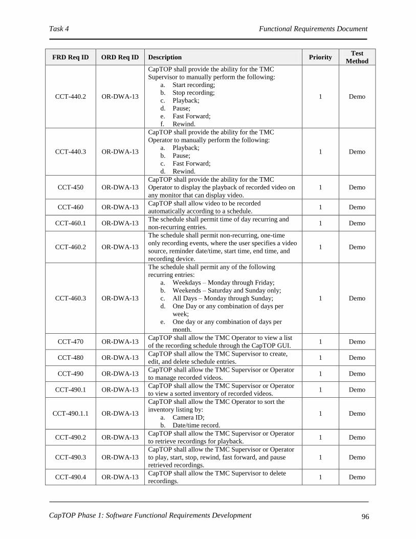
Task 4 Functional Requirements Document
CapTOP Phase 1: Software Functional Requirements Development 96
FRD Req ID ORD Req ID Description Priority Test
Method
CCT-440.2 OR-DWA-13
CapTOP shall provide the ability for the TMC
Supervisor to manually perform the following:
a. Start recording;
b. Stop recording;
c. Playback;
d. Pause;
e. Fast Forward;
f. Rewind.
1 Demo
CCT-440.3 OR-DWA-13
CapTOP shall provide the ability for the TMC
Operator to manually perform the following:
a. Playback;
b. Pause;
c. Fast Forward;
d. Rewind.
1 Demo
CCT-450 OR-DWA-13
CapTOP shall provide the ability for the TMC
Operator to display the playback of recorded video on
any monitor that can display video.
1 Demo
CCT-460 OR-DWA-13 CapTOP shall allow video to be recorded
automatically according to a schedule. 1 Demo
CCT-460.1 OR-DWA-13 The schedule shall permit time of day recurring and
non-recurring entries. 1 Demo
CCT-460.2 OR-DWA-13
The schedule shall permit non-recurring, one-time
only recording events, where the user specifies a video
source, reminder date/time, start time, end time, and
recording device.
1 Demo
CCT-460.3 OR-DWA-13
The schedule shall permit any of the following
recurring entries:
a. Weekdays – Monday through Friday;
b. Weekends – Saturday and Sunday only;
c. All Days – Monday through Sunday;
d. One Day or any combination of days per
week;
e. One day or any combination of days per
month.
1 Demo
CCT-470 OR-DWA-13 CapTOP shall allow the TMC Operator to view a list
of the recording schedule through the CapTOP GUI. 1 Demo
CCT-480 OR-DWA-13 CapTOP shall allow the TMC Supervisor to create,
edit, and delete schedule entries. 1 Demo
CCT-490 OR-DWA-13 CapTOP shall allow the TMC Supervisor or Operator
to manage recorded videos. 1 Demo
CCT-490.1 OR-DWA-13 CapTOP shall allow the TMC Supervisor or Operator
to view a sorted inventory of recorded videos. 1 Demo
CCT-490.1.1 OR-DWA-13
CapTOP shall allow the TMC Operator to sort the
inventory listing by:
a. Camera ID;
b. Date/time record.
1 Demo
CCT-490.2 OR-DWA-13 CapTOP shall allow the TMC Supervisor or Operator
to retrieve recordings for playback. 1 Demo
CCT-490.3 OR-DWA-13
CapTOP shall allow the TMC Supervisor or Operator
to play, start, stop, rewind, fast forward, and pause
retrieved recordings.
1 Demo
CCT-490.4 OR-DWA-13 CapTOP shall allow the TMC Supervisor to delete
recordings. 1 Demo

Task 4 Functional Requirements Document
CapTOP Phase 1: Software Functional Requirements Development 97
3.7.1.1.11 CCTV Logging Requirements
FRD Req ID ORD Req ID Description Priority Test
Method
CCT-500 UR-TO-11,
OR-TOM-1
CapTOP shall store and time stamp all operator and
system activities that pertain to CCTV cameras and
provide the output in a time sequential log.
C Demo
CCT-500.1
UR-TO-11,
OR-C2F-3,
OR-C2F-4,
OR-DWA-13
CapTOP shall have the capability to automatically log
the following user activities to the log database that
pertain to CCTV cameras:
a. any operator-initiated action resulting in a
request to access information;
b. any operator-initiated action that attempts to,
or results in, a change to a device;
c. when the operator issues a command to a
CCTV camera;
d. when the user changes the CCTV camera
configuration data;
e. when the user changes presets, tours, and
titles.
(Note: also refer to the LOG-* requirements).
C Demo
CCT-500.2 UR-TO-11
CapTOP shall have the capability to automatically log
the following system activities to the log database that
pertain to CCTV cameras:
a. any system-initiated action that attempts to, or
results in, a change to the device;
b. when the communication status changes (OK
to failed, and failed to OK);
c. changes in online-offline mode;
d. software application login;
e. software application logout.
(Note: also refer to the LOG-* requirements).
C Demo
CCT-500.3 UR-TO-11 CapTOP shall provide a window to display all logged
system and user activities for CCTV cameras. 1 Demo
CCT-500.4 UR-TO-11
CapTOP shall assign and store one of the following
action types when logging all CCTV camera activities:
a. operator input;
b. operator command transmission;
c. operator informational message;
d. operator error;
e. system warning;
f. system error;
g. system information message;
h. software application warning;
i. software application error;
j. software application information message.
1 Demo

Task 4 Functional Requirements Document
CapTOP Phase 1: Software Functional Requirements Development 98
FRD Req ID ORD Req ID Description Priority Test
Method
CCT-500.5 UR-TO-11
For log entries triggered by user actions, CapTOP shall
log the following:
a. Username;
b. Date stamp;
c. Time stamp;
d. Workstation ID;
e. Workstation IP address;
f. Action type;
g. Description of action (include the device ID,
description of action, and summary status of
device).
1 Demo
CCT-500.6 UR-TO-11
For log entries generated by the CapTOP applications,
CapTOP shall log the following:
a. Application name;
b. Date stamp;
c. Time stamp;
d. Action type;
e. Description of action (include the device ID,
command type and status of camera prior to
transmission).
1 Demo
CCT-500.7 UR-TO-11 CapTOP shall make all log entries read-only,
changeable by only the System Administrator. 1 Demo
CCT-510 OR-DWA-5
CapTOP shall have the capability to query and retrieve
all operator actions/commands that pertain to CCTV
cameras from the log by filtering on the following:
a. Workstation ID;
b. Workstation IP address;
c. Username;
d. Date stamp;
e. Time stamp;
f. Action type.
1 Demo
CCT-520 UR-TO-11,
OR-DDM-16
CapTOP shall be capable of generating a system alert
for the following:
a. changes in communication status (OK to
failed, and failed to OK);
b. changes in control mode (central, local,
central override);
c. changes in online-offline mode;
d. changes to CCTV camera configuration data.
1 Demo
3.7.1.1.12 CCTV Archiving Requirements
FRD Req ID ORD Req ID Description Priority Test
Method
CCT-530 OR-DWA-13
CapTOP or related third party software shall have the
capability to format and perform automated and
manually initiated migration of logged data that
pertains to CCTV cameras from the log database to the
archived database.
1 Demo
CCT-540 OR-DWA-13
CapTOP or related third party software shall have the
capability to format and perform automated and
manually initiated migration of operations data that
1 Demo
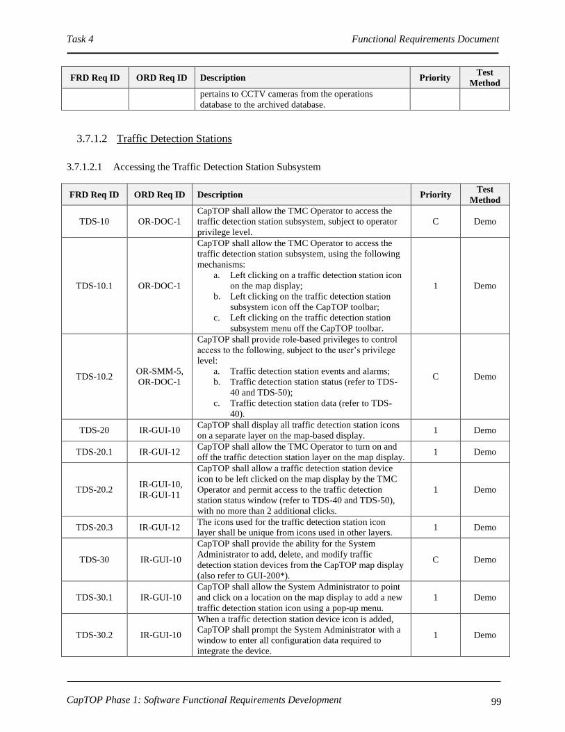
Task 4 Functional Requirements Document
CapTOP Phase 1: Software Functional Requirements Development 99
FRD Req ID ORD Req ID Description Priority Test
Method
pertains to CCTV cameras from the operations
database to the archived database.
3.7.1.2 Traffic Detection Stations
3.7.1.2.1 Accessing the Traffic Detection Station Subsystem
FRD Req ID ORD Req ID Description Priority Test
Method
TDS-10 OR-DOC-1
CapTOP shall allow the TMC Operator to access the
traffic detection station subsystem, subject to operator
privilege level.
C Demo
TDS-10.1 OR-DOC-1
CapTOP shall allow the TMC Operator to access the
traffic detection station subsystem, using the following
mechanisms:
a. Left clicking on a traffic detection station icon
on the map display;
b. Left clicking on the traffic detection station
subsystem icon off the CapTOP toolbar;
c. Left clicking on the traffic detection station
subsystem menu off the CapTOP toolbar.
1 Demo
TDS-10.2 OR-SMM-5,
OR-DOC-1
CapTOP shall provide role-based privileges to control
access to the following, subject to the user’s privilege
level:
a. Traffic detection station events and alarms;
b. Traffic detection station status (refer to TDS-
40 and TDS-50);
c. Traffic detection station data (refer to TDS-
40).
C Demo
TDS-20 IR-GUI-10 CapTOP shall display all traffic detection station icons
on a separate layer on the map-based display. 1 Demo
TDS-20.1 IR-GUI-12 CapTOP shall allow the TMC Operator to turn on and
off the traffic detection station layer on the map display. 1 Demo
TDS-20.2 IR-GUI-10,
IR-GUI-11
CapTOP shall allow a traffic detection station device
icon to be left clicked on the map display by the TMC
Operator and permit access to the traffic detection
station status window (refer to TDS-40 and TDS-50),
with no more than 2 additional clicks.
1 Demo
TDS-20.3 IR-GUI-12 The icons used for the traffic detection station icon
layer shall be unique from icons used in other layers. 1 Demo
TDS-30 IR-GUI-10
CapTOP shall provide the ability for the System
Administrator to add, delete, and modify traffic
detection station devices from the CapTOP map display
(also refer to GUI-200*).
C Demo
TDS-30.1 IR-GUI-10
CapTOP shall allow the System Administrator to point
and click on a location on the map display to add a new
traffic detection station icon using a pop-up menu.
1 Demo
TDS-30.2 IR-GUI-10
When a traffic detection station device icon is added,
CapTOP shall prompt the System Administrator with a
window to enter all configuration data required to
integrate the device.
1 Demo

Task 4 Functional Requirements Document
CapTOP Phase 1: Software Functional Requirements Development 100
FRD Req ID ORD Req ID Description Priority Test
Method
TDS-30.2.1
IR-GUI-10,
OR-TDCA-
20,
OR-TDCA-21
CapTOP shall allow the following configuration data to
be entered for each traffic detection station device to
enable the device to become operational in the system:
a. Station Number;
b. Controller/Access Point ID;
c. Description;
d. Controller/Access Point Model Number;
e. Location Information;
I. Location Description;
II. Street Address;
III. Road Name;
IV. Road Direction;
V. Exit Number;
VI. Milepost;
VII. Intersection/Interchange.
f. Road Classification (interstate,
freeway/expressway, principal arterial, minor
arterial, collector, local);
g. Online-Offline Mode ( static – set by System
Administrator or Maintenance Technician);
h. Collection Mode (count, speed, occupancy,
speed/volume/occupancy);
i. Communication Type (dialup serial, network
serial, IP);
j. Group Name;
k. Speed Edge (leading edge, trailing edge,
average);
l. Reporting Filter (enable/disable all vehicle
reporting);
m. Valid Threshold (limit for valid speed);
n. Adaptive Holdover (length in feed for the
holdover calculation);
o. Clock offset (number of seconds that event
times will be shifted before processing);
p. Multidrop Information;
I. Drop Address;
II. Channel ID;
III. Port Name.
q. IP Information;
I. IP Address;
II. Port Number;
III. Local Port Number;
IV. VPN Password.
r. Serial Information;
I. Baud Rate;
II. No. Data Bits;
III. Parity;
1 Demo

Task 4 Functional Requirements Document
CapTOP Phase 1: Software Functional Requirements Development 101
FRD Req ID ORD Req ID Description Priority Test
Method
IV. No. Stop Bits;
V. H/W Flow Control;
VI. S/W Flow Control.
s. Lane information:
I. Number of Lanes;
II. For each Lane:
i. Lane Number;
ii. Direction;
iii. Movement (turning lane, through
lane, shared lane);
iv. Onset Filter;
v. Detect Z Threshold;
vi. Un-detect Z Threshold;
vii. Un-detect X Threshold;
viii. Holdover;
ix. Swap X/Y (yes/no);
x. Stop-bar Recalibrate Timeout;
xi. Count Recalibrate Timeout;
xii. Distance Between Sensor.
t. Time Slot;
u. RF Channel;
v. Recalibration;
w. NTCIP Community;
x. Firmware Version;
y. Cabinet Number;
z. Model Number of Sensor;
aa. Protocol;
bb. Link ID;
cc. Polling Enabled (yes/no, defaults to yes);
dd. Comm Loss Timeout (seconds in .1
increments);
ee. Associated CCTV;
ff. TMDD Information;
I. Horizontal Datum (WGS84,
84EGM96, NAD83);
II. Latitude (decimal degrees);
III. Longitude (decimal degrees);
IV. Vertical Datum (WGS84);
V. Height (-127 to 127);
VI. Vertical Level (-127 to 127).
TDS-30.2.2 IR-GUI-10
When a traffic detection station device icon is added,
CapTOP shall prompt the System Administrator or
Maintenance Technician with setting the device online
or offline.
1 Demo
TDS-30.2.3 IR-GUI-10
If the user enters a latitude/longitude pair for the device,
the device icon location on the map shall be updated
automatically based on the coordinates specified (and
not where there user clicked to create the icon).
1 Demo

Task 4 Functional Requirements Document
CapTOP Phase 1: Software Functional Requirements Development 102
FRD Req ID ORD Req ID Description Priority Test
Method
TDS-30.3 IR-GUI-10,
IR-GUI-11
CapTOP shall allow a traffic detection station device
icon to be right clicked on the map display and permit
access to the following functions by the System
Administrator or Maintenance Technician, with no
more than 2 additional clicks:
a. setting the online-offline mode;
b. entering, deleting, or modifying configuration
information;
c. allowing the device icon to be relocated on the
map display;
d. displaying the traffic detection station status
window;
e. allowing the device icon to be deleted.
1 Demo
TDS-30.4 OR-IM-4
CapTOP shall strictly enforce the use of pull-down
menus, radio buttons, or selection boxes when any of
the following fields are entered by the user:
a. Street Address/Block;
b. Road Name;
c. Road Direction;
d. Exit Number;
e. Milepost;
f. Intersection/Interchange;
g. Road Classification (interstate,
freeway/expressway, principal arterial, minor
arterial, collector, local);
h. Online-Offline Mode (online/offline);
i. Collection Mode (count, speed, occupancy,
speed/volume/occupancy);
j. Communication Type (dialup serial, network
serial, IP);
k. Speed Edge (leading edge, trailing edge,
average);
l. Reporting Filter (enable/disable all vehicle
reporting);
m. Direction;
n. Movement (turning lane, through lane, shared
lane);
o. Protocol;
p. Link ID;
q. Polling Enabled (yes/no, defaults to yes);
r. Associated CCTV.
1 Demo
TDS-30.4.1 OR-IM-4 CapTOP shall restrict the use of free-form text entry on
the fields identified above. 1 Demo
TDS-30.4.2 OR-IM-4
CapTOP shall allow the user to type the 1st 3 characters
in each field and the system will provide a filtered list
of selections for that field that begin with the 1st 3
characters typed by the user.
2 Demo
TDS-30.4.3 OR-IM-4
CapTOP shall allow the user to select “Other” and enter
in free form text when a desired entry cannot be found
in the list.
1 Demo
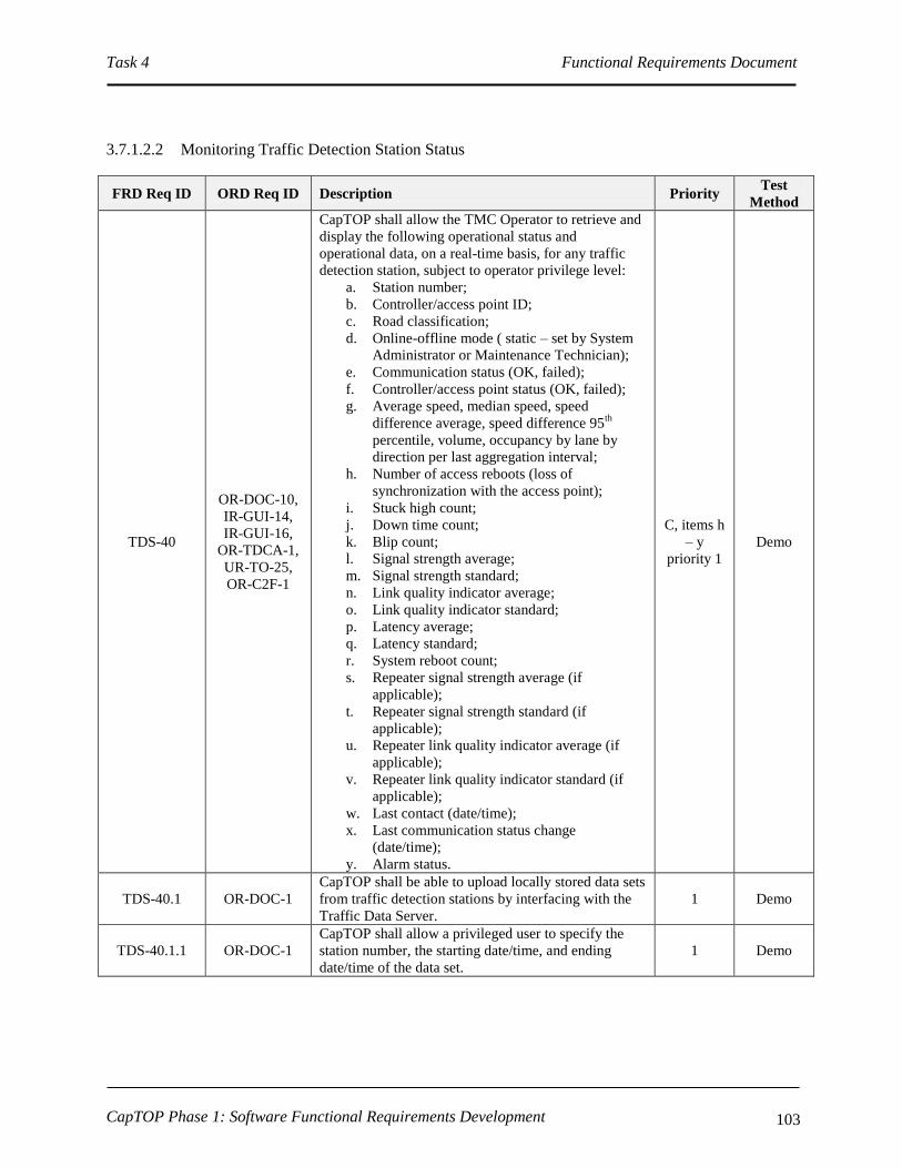
Task 4 Functional Requirements Document
CapTOP Phase 1: Software Functional Requirements Development 103
3.7.1.2.2 Monitoring Traffic Detection Station Status
FRD Req ID ORD Req ID Description Priority Test
Method
TDS-40
OR-DOC-10,
IR-GUI-14,
IR-GUI-16,
OR-TDCA-1,
UR-TO-25,
OR-C2F-1
CapTOP shall allow the TMC Operator to retrieve and
display the following operational status and
operational data, on a real-time basis, for any traffic
detection station, subject to operator privilege level:
a. Station number;
b. Controller/access point ID;
c. Road classification;
d. Online-offline mode ( static – set by System
Administrator or Maintenance Technician);
e. Communication status (OK, failed);
f. Controller/access point status (OK, failed);
g. Average speed, median speed, speed
difference average, speed difference 95th
percentile, volume, occupancy by lane by
direction per last aggregation interval;
h. Number of access reboots (loss of
synchronization with the access point);
i. Stuck high count;
j. Down time count;
k. Blip count;
l. Signal strength average;
m. Signal strength standard;
n. Link quality indicator average;
o. Link quality indicator standard;
p. Latency average;
q. Latency standard;
r. System reboot count;
s. Repeater signal strength average (if
applicable);
t. Repeater signal strength standard (if
applicable);
u. Repeater link quality indicator average (if
applicable);
v. Repeater link quality indicator standard (if
applicable);
w. Last contact (date/time);
x. Last communication status change
(date/time);
y. Alarm status.
C, items h
– y
priority 1
Demo
TDS-40.1 OR-DOC-1
CapTOP shall be able to upload locally stored data sets
from traffic detection stations by interfacing with the
Traffic Data Server.
1 Demo
TDS-40.1.1 OR-DOC-1
CapTOP shall allow a privileged user to specify the
station number, the starting date/time, and ending
date/time of the data set.
1 Demo

Task 4 Functional Requirements Document
CapTOP Phase 1: Software Functional Requirements Development 104
FRD Req ID ORD Req ID Description Priority Test
Method
TDS-40.2 OR-DOC-1
CapTOP shall use data from the following sources to
determine operational status:
a. data reported from the traffic detection
stations;
b. data gained by CapTOP in attempts to
communicate with the traffic detection
stations;
c. online/offline information entered manually
by authorized CapTOP users.
1 Demo
TDS-50
SR-SYS-2,
IR-GUI-36,
IR-GUI-26
CapTOP shall allow privileged users to simultaneously
view traffic detection station status, which is refreshed
automatically by the system based on the polling
interval, using the following methods:
a. Color coded icons on the map display;
b. Via the traffic detection station status window
which lists all traffic detection stations, the
station number, controller/access point ID,
location, online-offline mode, communication
status, and controller/access point status.
C Demo
TDS-50.1 IR-GUI-28,
IR-GUI-26
CapTOP shall use the following colors for device icon
states:
a. Black = device failure, but online in CapTOP;
b. Orange = communication failure;
c. Gray = offline.
d. Maroon = online and speed is between 0%
and 25% of free flow speed;
e. Red = online and speed is between 25% and
50% of free flow speed;
f. Yellow = online and speed is between 50%
and 75% of free flow;
g. Light Green = online and speed is between
75% and 90% of free flow speed;
h. Dark Green = online and speed is > 90% of
free flow speed.
. Also refer to GUI-150* requirements for an
understanding of how traffic condition data is
displayed on a per link basis.
C Demo
TDS-50.1.1 IR-GUI-28,
IR-GUI-26
CapTOP shall use the following rules for device icon
states:
a. If the device is online but in communication
failure, the device icon color should be that of
a device with a communication failure;
b. In order for the device icon to be red, maroon,
yellow, light green, or dark green, the device
must be both online and have OK
communication.
C Demo
TDS-50.2 IR-GUI-31,
IR-GUI-29
The refresh rate for icon status and for the data in the
status window shall be configurable and based upon
the polling rate.
1 Demo
TDS-50.3 IR-GUI-31
CapTOP shall allow the user to obtain summary status
information (refer to TDS-40 items a through g, l, m,
and w, x, and y for the list of fields) by hovering over a
TDS icon.
1 Demo

Task 4 Functional Requirements Document
CapTOP Phase 1: Software Functional Requirements Development 105
FRD Req ID ORD Req ID Description Priority Test
Method
TDS-50.4 IR-GUI-29
CapTOP shall allow the user to select on any traffic
detection station in the TDS status window (refer to
TDS-50 item b) and view all details (full status,
configuration information) pertaining to that traffic
detection station.
1 Demo
TDS-60
SR-SYS-2,
IR-GUI-31,
IR-GUI-32
CapTOP shall provide a menu option to search for a
traffic detection station by the following methods:
a. station number;
b. controller/access point ID;
c. IP address/drop address/channel ID of the
controller/access point;
d. group name;
e. street name;
f. geographical address;
g. intersection/interchange.
C Demo
TDS-60.1 SR-SYS-2,
IR-GUI-31
CapTOP shall allow the TMC Operator to search for
traffic detection stations using a rubber-band style box
on the map display to search an area.
C Demo
TDS-60.2
SR-SYS-2,
IR-GUI-31,
OR-TDCA-5
The result of each search shall be a list of traffic
detection stations that are sorted, by default, by station
number.
1 Demo
TDS-60.3
SR-SYS-2,
IR-GUI-31,
OR-TDCA-5
The result of each search shall be a list of traffic
detection stations sortable by station number,
controller/access point ID, IP address/drop
address/channel ID, group name, street name,
geographical address, and intersection/interchange.
1 Demo
TDS-70 IR-GUI-14
CapTOP shall provide a monitoring interface to the
existing traffic detection station server or
controller/access point through CapTOP’s new Traffic
Data Server for monitoring the TDS stations.
Refer to TDA-10* for more information.
1 Demo
TDS-70.1 OR-DOC-3,
OR-TDCA-6
CapTOP’s Traffic Data Server (developed by others,
or optionally, by the CapTOP developer) shall
interface with the traffic detection station SNAPS
(Sensys Networks Archive, Proxy and Statistics)
server or controller/access point in accordance with the
traffic detection station software API from Sensys, Inc.
to access traffic detection station data.
Note: DDOT is currently in negotiation with Sensys to
obtain proprietary file format and communication
protocol documentation for this wireless in-pavement
sensor. This requirement is pending based on the
results of this effort.
1 Demo
TDS-70.1.1
OR-DOC-2,
OR-DOC-3,
IR-GUI-29
CapTOP shall support a polling interval range from 0
to 99999 seconds, where zero indicates no polling. 1 Demo
TDS-70.1.1.1
OR-DOC-2,
OR-DOC-3,
IR-GUI-29
The default polling interval shall be once every 1
minutes. 1 Demo
TDS-70.2 IR-GUI-14 CapTOP shall be able to request traffic detection
station status and obtain status response data through 1 Demo

Task 4 Functional Requirements Document
CapTOP Phase 1: Software Functional Requirements Development 106
FRD Req ID ORD Req ID Description Priority Test
Method
the Traffic Data Server.
TDS-70.3 IR-GUI-14 CapTOP shall prohibit traffic detection station
controller/access point changes through this interface. 1 Demo
TDS-80
OR-C2F-3,
OR-C2F-4,
OR-DWA-13
CapTOP shall be able to store all traffic detection
station operational data (refer to TDS-40) in the
CapTOP operations database for each polling cycle.
1 Demo
TDS-80.1 OR-TDCA-3 CapTOP shall store the speed, volume, and occupancy
data by road name, interchange, and station number. 1 Demo
TDS-80.2 OR-TDCA-3
CapTOP shall be able to use the volumes to compute
the Annual Average Daily Traffic (AADT) counts for
each year.
1 Demo
TDS-80.3 OR-TDCA-3 CapTOP shall be able to use the volumes to compute
the AADT counts for each season of the year. 1 Demo
TDS-90 OR-TDCA-21
CapTOP shall be able to, at the System
Administrator’s or Maintenance Technician’s request,
upload and store all traffic detection station field
controller/access point configuration data in the
CapTOP central system device configuration database
for traffic detection stations.
1 Demo
3.7.1.2.3 Traffic Detection Station Reports
FRD Req ID ORD Req ID Description Priority Test
Method
TDS-100 OR-TDCA-4,
OR-TDCA-9
CapTOP shall be able to display and print data from
traffic detection stations in both tabular and graphical
formats.
2 Demo
TDS-110
SR-SYS-22,
SR-SYS-36,
OR-DOC-4,
IR-GUI-8
CapTOP shall be able to automatically generate real-
time tabular reports that show the real-time operational
status and operational data of all traffic detection
stations.
2 Demo
TDS-110.1
SR-SYS-22,
SR-SYS-36,
OR-DOC-4,
IR-GUI-8
CapTOP shall provide the following information in the
traffic detection station status summary report:
a. Station number;
b. Controller/access point ID;
c. Location;
d. Number of lanes;
e. Alarm status;
f. Online-offline mode;
g. Controller/access point status (OK, failed);
h. Communication status (OK, failed).
2 Demo
TDS-110.2
SR-SYS-22,
SR-SYS-36,
OR-DOC-4,
IR-GUI-8
CapTOP shall provide the following information in the
traffic detection station extended status report:
a. Station number;
b. Controller/access point ID;
c. Location;
d. Road classification;
e. Online-offline mode ( static – set by System
Administrator or Maintenance Technician);
f. Communication status (OK, failed);
g. Controller/access point status (OK, failed);
h. Number of lanes;
i. Average speed, median speed, speed
2 Demo

Task 4 Functional Requirements Document
CapTOP Phase 1: Software Functional Requirements Development 107
FRD Req ID ORD Req ID Description Priority Test
Method
difference average, speed difference 95th
percentile, volume, and occupancy by lane by
direction per last aggregation interval;
j. Last contact (date/time);
k. Last communication status change
(date/time);
l. Alarm status.
TDS-110.2.1
SR-SYS-22,
SR-SYS-36,
OR-DOC-4,
IR-GUI-8
CapTOP shall be able to display graphical reports in a
Microsoft Excel-like 2-dimensional or 3-dimensional
format using data in the extended status report.
2 Demo
TDS-110.3
SR-SYS-22,
SR-SYS-36,
OR-DOC-4,
IR-GUI-8
CapTOP shall be able to provide a full device
configuration report for a user entered Station number
or Controller ID.
2 Demo
TDS-120 OR-DWA-7,
OR-DWA-5
CapTOP shall be able to produce the following
performance reports for evaluating the performance of
traffic detection stations, using data in the CapTOP
operations and archived databases:
a. Number of times a traffic detection station
transitioned from online to offline over a
specified time period;
b. Number of times a traffic detection station
transitioned from no device failure to device
failure over a specified time period;
c. Number of times a traffic detection station
transitioned from no communication to
communication failure over a specified time
period;
d. A report showing missing data from each
traffic detection station.
2 Demo
TDS-130 OR-DWA-7,
OW-DWA-5
CapTOP shall be able to produce a traffic detection
station report by allowing the user to specify a station
number, starting date/time, ending date time, and a
reporting interval (5 minute, 15 minute, hourly, daily,
monthly, seasonal, quarterly, bi-annual, annual).
2 Demo
TDS-140 OR-DWA-7,
OW-DWA-5
CapTOP shall be able to produce the following reports
by allowing the user to specify a station number,
starting date/time, ending date time, and a reporting
interval (5 minute, 15 minute, hourly, daily, monthly,
seasonal, quarterly, bi-annual, annual):
a. Speed Peak Period Average;
b. Speed Daily Average;
c. Speed Weekly Average;
d. Speed Monthly Average;
e. Volume Peak Period Average;
f. Volume Daily Average;
g. Volume Weekly Average;
h. Volume Monthly Average;
i. Occupancy Peak Period Average;
j. Occupancy Daily Average;
k. Occupancy Weekly Average;
l. Occupancy Monthly Average.
2 Demo
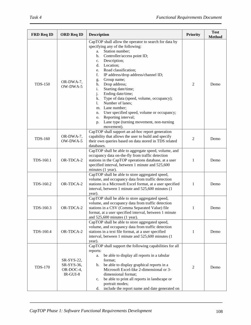
Task 4 Functional Requirements Document
CapTOP Phase 1: Software Functional Requirements Development 108
FRD Req ID ORD Req ID Description Priority Test
Method
TDS-150 OR-DWA-7,
OW-DWA-5
CapTOP shall allow the operator to search for data by
specifying any of the following:
a. Station number;
b. Controller/access point ID;
c. Description;
d. Location;
e. Road classification;
f. IP address/drop address/channel ID;
g. Group name;
h. Drop address;
i. Starting date/time;
j. Ending date/time;
k. Type of data (speed, volume, occupancy);
l. Number of lanes;
m. Lane number;
n. User specified speed, volume or occupancy;
o. Reporting interval;
p. Lane type (turning movement, non-turning
movement).
2 Demo
TDS-160 OR-DWA-7,
OW-DWA-5
CapTOP shall support an ad-hoc report generation
capability that allows the user to build and specify
their own queries based on data stored in TDS related
databases.
2 Demo
TDS-160.1 OR-TDCA-2
CapTOP shall be able to aggregate speed, volume, and
occupancy data on-the-fly from traffic detection
stations in the CapTOP operations database, at a user
specified interval, between 1 minute and 525,600
minutes (1 year).
1 Demo
TDS-160.2 OR-TDCA-2
CapTOP shall be able to store aggregated speed,
volume, and occupancy data from traffic detection
stations in a Microsoft Excel format, at a user specified
interval, between 1 minute and 525,600 minutes (1
year).
1 Demo
TDS-160.3 OR-TDCA-2
CapTOP shall be able to store aggregated speed,
volume, and occupancy data from traffic detection
stations in a CSV (Comma Separated Value) file
format, at a user specified interval, between 1 minute
and 525,600 minutes (1 year).
1 Demo
TDS-160.4 OR-TDCA-2
CapTOP shall be able to store aggregated speed,
volume, and occupancy data from traffic detection
stations in a text file format, at a user specified
interval, between 1 minute and 525,600 minutes (1
year).
1 Demo
TDS-170
SR-SYS-22,
SR-SYS-36,
OR-DOC-4,
IR-GUI-8
CapTOP shall support the following capabilities for all
reports:
a. be able to display all reports in a tabular
format;
b. be able to display graphical reports in a
Microsoft Excel-like 2-dimensional or 3-
dimensional format;
c. be able to print all reports in landscape or
portrait modes;
d. include the report name and date generated on
2 Demo
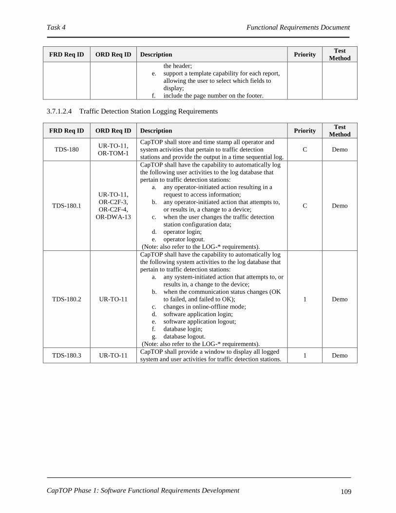
Task 4 Functional Requirements Document
CapTOP Phase 1: Software Functional Requirements Development 109
FRD Req ID ORD Req ID Description Priority Test
Method
the header;
e. support a template capability for each report,
allowing the user to select which fields to
display;
f. include the page number on the footer.
3.7.1.2.4 Traffic Detection Station Logging Requirements
FRD Req ID ORD Req ID Description Priority Test
Method
TDS-180 UR-TO-11,
OR-TOM-1
CapTOP shall store and time stamp all operator and
system activities that pertain to traffic detection
stations and provide the output in a time sequential log.
C Demo
TDS-180.1
UR-TO-11,
OR-C2F-3,
OR-C2F-4,
OR-DWA-13
CapTOP shall have the capability to automatically log
the following user activities to the log database that
pertain to traffic detection stations:
a. any operator-initiated action resulting in a
request to access information;
b. any operator-initiated action that attempts to,
or results in, a change to a device;
c. when the user changes the traffic detection
station configuration data;
d. operator login;
e. operator logout.
(Note: also refer to the LOG-* requirements).
C Demo
TDS-180.2 UR-TO-11
CapTOP shall have the capability to automatically log
the following system activities to the log database that
pertain to traffic detection stations:
a. any system-initiated action that attempts to, or
results in, a change to the device;
b. when the communication status changes (OK
to failed, and failed to OK);
c. changes in online-offline mode;
d. software application login;
e. software application logout;
f. database login;
g. database logout.
(Note: also refer to the LOG-* requirements).
1 Demo
TDS-180.3 UR-TO-11 CapTOP shall provide a window to display all logged
system and user activities for traffic detection stations. 1 Demo

Task 4 Functional Requirements Document
CapTOP Phase 1: Software Functional Requirements Development 110
FRD Req ID ORD Req ID Description Priority Test
Method
TDS-180.4 UR-TO-11
CapTOP shall assign and store one of the following
action types when logging all traffic detection station
activities:
a. operator input;
b. operator command transmission (if
applicable);
c. operator informational message;
d. operator error;
e. system warning;
f. system error;
g. system information message;
h. software application warning;
i. software application error;
j. software application information message.
1 Demo
TDS-180.5 UR-TO-11
For log entries triggered by user actions, CapTOP shall
log the following:
a. Username;
b. Date stamp;
c. Time stamp;
d. Workstation ID;
e. Workstation IP address;
f. Action type;
g. Description of action (include the device ID,
description of action, and summary status of
device).
1 Demo
TDS-180.6 UR-TO-11
For log entries generated by the CapTOP applications,
CapTOP shall log the following:
a. Application name;
b. Date stamp;
c. Time stamp;
d. Action type;
e. Description of action.
1 Demo
TDS-180.7 UR-TO-11 CapTOP shall make all log entries read-only,
changeable by only the System Administrator. 1 Demo
TDS-190 OR-DWA-5
CapTOP shall have the capability to query and retrieve
all operator actions/commands that pertain to traffic
detection stations from the log by filtering on the
following:
a. workstation ID;
b. workstation IP address;
c. username;
d. date stamp;
e. time stamp;
f. action type.
1 Demo
TDS-200 UR-TO-11,
OR-DDM-16
CapTOP shall be capable of generating a system alert
for the following:
a. changes in communication status (OK to
failed, and failed to OK);
b. changes in online-offline mode;
c. changes to traffic detection station
configuration data.
1 Demo

Task 4 Functional Requirements Document
CapTOP Phase 1: Software Functional Requirements Development 111
3.7.1.2.5 Traffic Detection Station Archiving Requirements
FRD Req ID ORD Req ID Description Priority Test
Method
TDS-210 OR-DWA-13
CapTOP or related third party software shall have the
capability to format and perform automated and
manually initiated migration of logged data that
pertains to traffic detection stations from the log
database to the archived database.
1 Demo
TDS-220 OR-DWA-13
CapTOP or related third party software shall have the
capability to format and perform automated and
manually initiated migration of operations data that
pertains to traffic detection stations from the
operations database to the archived database.
1 Demo
TDS-220.1
OR-TDCA-1,
OR-TDCA-2,
OR-TDCA-3
CapTOP shall be able to store aggregated speed,
volume, and occupancy data from traffic detection
stations in the CapTOP archived database, at a user
specified interval, between 1 minute and 525,600
minutes (1 year).
1 Demo
3.7.1.3 Permanent Count Stations
3.7.1.3.1 Accessing the Permanent Count Station Subsystem
FRD Req
ID
ORD Req
ID Description Priority
Test
Method
PCS-10 OR-DOC-1
CapTOP shall allow the TMC Operator to access the
permanent count station subsystem, subject to operator
privilege level.
C Demo
PCS-10.1 OR-DOC-1
CapTOP shall allow the TMC Operator to access the
permanent count station subsystem, using the following
mechanisms:
a. Left clicking on a permanent count station icon on the
map display;
b. Left clicking on the permanent count station
subsystem icon off the CapTOP toolbar;
c. Left clicking on the permanent count station
subsystem menu off the CapTOP toolbar.
1 Demo
PCS-10.2
OR-SMM-
5, OR-
DOC-1
CapTOP shall provide role-based privileges to control access
to the following, subject to the user’s privilege level:
a. Permanent count station events and alarms;
b. Permanent count station status (refer to PCS-40 and
PCS-50);
c. Permanent count station data (refer to PCS-40).
C Demo
PCS-20 IR-GUI-10 CapTOP shall display all permanent count station icons on a
separate layer on the map-based display. 1 Demo
PCS-20.1 IR-GUI-12 CapTOP shall allow the TMC Operator to turn on and off the
permanent count station layer on the map display. 1 Demo
PCS-20.2 IR-GUI-11
CapTOP shall allow the TMC Operator to left click a
permanent count station icon and invoke the permanent count
station status window (refer to PCS-40 and PCS-50), with no
more than 2 additional clicks.
1 Demo
PCS-20.3 IR-GUI-12 The icons used for the permanent count station icon layer shall
be unique from icons used in other layers. 1 Demo

Task 4 Functional Requirements Document
CapTOP Phase 1: Software Functional Requirements Development 112
FRD Req
ID
ORD Req
ID Description Priority
Test
Method
PCS-30 IR-GUI-10
CapTOP shall provide the ability for the System Administrator
to add, delete, and modify permanent count station devices
from the CapTOP map display (also refer to GUI-200*).
C Demo
PCS-30.1 IR-GUI-10
CapTOP shall allow the System Administrator to point and
click on a location on the map display to add a new permanent
count station icon using a pop-up menu.
1 Demo
PCS-30.2 IR-GUI-10
When a permanent count station device icon is added,
CapTOP shall prompt the System Administrator with a
window to enter all configuration data required to integrate the
device.
1 Demo
PCS-30.2.1
IR-GUI-10,
OR-TDCA-
20,
OR-TDCA-
21
CapTOP shall allow the following configuration data to be
entered for each permanent count station device to enable the
device to become operational in the system:
a. Station Number;
b. Station Type (portable, permanent);
c. Controller ID;
d. Description;
e. Controller Model Number;
f. Location Information;
I. Location Description;
II. Street Address;
III. Road Name;
IV. Road Direction;
V. Exit Number;
VI. Milepost;
VII. Intersection/Interchange.
g. Road Classification (interstate, freeway/expressway,
principal arterial, minor arterial, collector, local);
h. Online-Offline Mode ( static – set by System
Administrator or Maintenance Technician);
i. Communication Type (dialup serial, network serial,
IP);
j. Multidrop Information;
I. Drop Address;
II. Channel ID;
III. Port Name.
k. IP Information;
I. IP Address;
II. Port Number.
l. Serial Information;
I. Baud Rate;
II. No. Data Bits;
III. Parity;
IV. No. Stop Bits;
V. H/W Flow Control;
VI. S/W Flow Control.
m. Classification information:
I. Number of classes;
1 Demo

Task 4 Functional Requirements Document
CapTOP Phase 1: Software Functional Requirements Development 113
FRD Req
ID
ORD Req
ID Description Priority
Test
Method
II. For each class:
i. Class Number;
ii. Number of axles;
iii. Minimum length of axle;
iv. Maximum length of axle.
n. Lane information:
I. Number of lanes;
II. For each lane:
i. Lane Number;
ii. Direction;
iii. Movement (turning lane, through
lane, shared lane);
iv. Occupancy error;
v. Distance between loops.
o. NTCIP Community;
p. Firmware Version;
q. Cabinet Number;
r. Model Number of Sensor;
s. Protocol;
t. Link ID;
u. Polling Enabled (yes/no, defaults to yes);
v. Comm Loss Timeout (seconds in .1 increments);
w. Associated CCTV;
x. TMDD Information;
I. Horizontal Datum (WGS84, 84EGM96,
NAD83);
II. Latitude (decimal degrees);
III. Longitude (decimal degrees);
IV. Vertical Datum (WGS84);
V. Height (-127 to 127);
VI. Vertical Level (-127 to 127).
PCS-30.2.2 IR-GUI-10
When a permanent count station device icon is added,
CapTOP shall prompt the System Administrator or
Maintenance Technician with setting the device online or
offline.
1 Demo
PCS-30.2.3 IR-GUI-10
If the user enters a latitude/longitude pair for the device, the
device icon location on the map shall be updated automatically
based on the coordinates specified (and not where there user
clicked to create the icon).
1 Demo

Task 4 Functional Requirements Document
CapTOP Phase 1: Software Functional Requirements Development 114
FRD Req
ID
ORD Req
ID Description Priority
Test
Method
PCS-30.3 IR-GUI-10
CapTOP shall allow a permanent count station device icon to
be right clicked on the map display and permit access to the
following functions by the System Administrator or
Maintenance Technician, with no more than 2 additional
clicks:
a. setting the online-offline mode;
b. entering, deleting, or modifying configuration
information;
c. allowing the device icon to be relocated on the map
display;
d. allowing the device icon to be deleted.
1 Demo
PCS-30.4 OR-IM-4
CapTOP shall strictly enforce the use of pull-down menus,
radio buttons, or selection boxes when any of the following
fields are entered by the user:
a. Street Address/Block;
b. Road Name;
c. Road Direction;
d. Exit Number;
e. Milepost;
f. Intersection/Interchange;
g. Road Classification (interstate, freeway/expressway,
principal arterial, minor arterial, collector, local);
h. Online-Offline Mode (online/offline);
i. Collection Mode (count, speed, occupancy,
speed/volume/occupancy);
j. Communication Type (dialup serial, network serial,
IP);
k. Direction;
l. Movement (turning lane, through lane, shared lane);
m. Protocol;
n. Link ID;
o. Polling Enabled (yes/no, defaults to yes);
p. Associated CCTV.
1 Demo
PCS-30.4.1 OR-IM-4 CapTOP shall restrict the use of free-form text entry on the
fields identified above. 1 Demo
PCS-30.4.2 OR-IM-4
CapTOP shall allow the user to type the 1st 3 characters in
each field and the system will provide a filtered list of
selections for that field that begin with the 1st 3 characters
typed by the user.
2 Demo
PCS-30.4.3 OR-IM-4 CapTOP shall allow the user to select “Other” and enter in
free form text when a desired entry cannot be found in the list. 1 Demo

Task 4 Functional Requirements Document
CapTOP Phase 1: Software Functional Requirements Development 115
3.7.1.3.2 Monitoring Permanent Count Station Status
FRD Req ID ORD Req ID Description Priority Test
Method
PCS-40
OR-DOC-10,
IR-GUI-14,
IR-GUI-16,
OR-TDCA-6,
UR-TO-25,
OR-C2F-1
CapTOP shall allow the TMC Operator to retrieve and
display the following operational status and
operational data, on a real-time basis, from any
permanent count station, subject to operator privilege
level:
a. Station number;
b. Controller ID;
c. Station type (portable, permanent);
d. Road classification;
e. Online-offline mode ( static – set by System
Administrator or Maintenance Technician);
f. Communication status (OK, failed);
g. Controller status (OK, failed);
h. Speed, volume, occupancy by lane and by
direction per last aggregation interval;
i. Classification data by lane and by direction
per last aggregation interval;
j. Lane status (OK, failed, standby);
k. Last contact (date/time);
l. Last communication status change
(date/time);
m. Alarm status.
C, items i
- m
priority 1
Demo
PCS-40.1 OR-DOC-1
CapTOP shall be able to upload locally stored data sets
from permanent count stations by interfacing with the
Traffic Data Server.
1 Demo
PCS-40.1.1 OR-DOC-1
CapTOP shall allow a privileged user to specify the
station number, the starting date/time, and ending
date/time of the data set.
1 Demo
PCS-40.2 OR-DOC-1
CapTOP shall use data from the following sources to
determine operational status:
a. data reported from the permanent count
stations;
b. data gained by CapTOP in attempts to
communicate with the permanent count
stations;
c. online/offline information entered manually
by authorized CapTOP users.
1 Demo
PCS-50
SR-SYS-2,
IR-GUI-36,
IR-GUI-26
CapTOP shall allow privileged users to simultaneously
view permanent count station status, which is refreshed
automatically by the system based on the polling
interval, using the following methods:
a. Color coded icons on the map display;
b. Via the permanent count station status
window which lists all permanent count
stations, the station number, controller ID,
location, online-offline mode, communication
status, and controller status.
C Demo
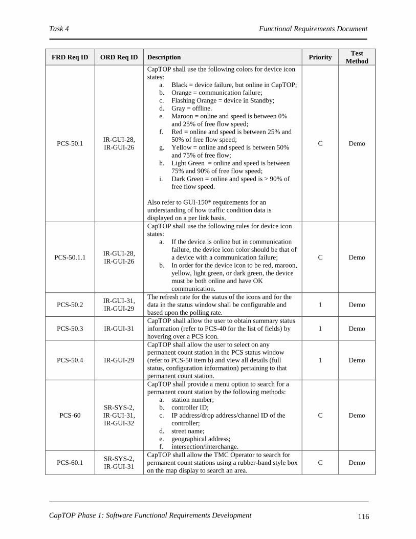
Task 4 Functional Requirements Document
CapTOP Phase 1: Software Functional Requirements Development 116
FRD Req ID ORD Req ID Description Priority Test
Method
PCS-50.1 IR-GUI-28,
IR-GUI-26
CapTOP shall use the following colors for device icon
states:
a. Black = device failure, but online in CapTOP;
b. Orange = communication failure;
c. Flashing Orange = device in Standby;
d. Gray = offline.
e. Maroon = online and speed is between 0%
and 25% of free flow speed;
f. Red = online and speed is between 25% and
50% of free flow speed;
g. Yellow = online and speed is between 50%
and 75% of free flow;
h. Light Green = online and speed is between
75% and 90% of free flow speed;
i. Dark Green = online and speed is > 90% of
free flow speed.
Also refer to GUI-150* requirements for an
understanding of how traffic condition data is
displayed on a per link basis.
C Demo
PCS-50.1.1 IR-GUI-28,
IR-GUI-26
CapTOP shall use the following rules for device icon
states:
a. If the device is online but in communication
failure, the device icon color should be that of
a device with a communication failure;
b. In order for the device icon to be red, maroon,
yellow, light green, or dark green, the device
must be both online and have OK
communication.
C Demo
PCS-50.2 IR-GUI-31,
IR-GUI-29
The refresh rate for the status of the icons and for the
data in the status window shall be configurable and
based upon the polling rate.
1 Demo
PCS-50.3 IR-GUI-31
CapTOP shall allow the user to obtain summary status
information (refer to PCS-40 for the list of fields) by
hovering over a PCS icon.
1 Demo
PCS-50.4 IR-GUI-29
CapTOP shall allow the user to select on any
permanent count station in the PCS status window
(refer to PCS-50 item b) and view all details (full
status, configuration information) pertaining to that
permanent count station.
1 Demo
PCS-60
SR-SYS-2,
IR-GUI-31,
IR-GUI-32
CapTOP shall provide a menu option to search for a
permanent count station by the following methods:
a. station number;
b. controller ID;
c. IP address/drop address/channel ID of the
controller;
d. street name;
e. geographical address;
f. intersection/interchange.
C Demo
PCS-60.1 SR-SYS-2,
IR-GUI-31
CapTOP shall allow the TMC Operator to search for
permanent count stations using a rubber-band style box
on the map display to search an area.
C Demo

Task 4 Functional Requirements Document
CapTOP Phase 1: Software Functional Requirements Development 117
FRD Req ID ORD Req ID Description Priority Test
Method
PCS-60.2
SR-SYS-2,
IR-GUI-31,
OR-TDCA-10
The result of each search shall be a list of permanent
count stations that are sorted, by default, by station
number.
1 Demo
PCS-60.3
SR-SYS-2,
IR-GUI-31,
OR-TDCA-10
The result of each search shall be a list of permanent
count stations sortable by station number, controller
ID, IP address/drop address/channel ID, street name,
geographical address, and intersection/interchange.
1 Demo
PCS-70 IR-GUI-14
CapTOP shall provide a monitoring interface to the
existing permanent count station server through
CapTOP’s new Traffic Data Server for monitoring the
PCS stations.
Refer to TDA-10* for more information.
C Demo
PCS-70.1 OR-DOC-3,
OR-TDCA-6
CapTOP’s Traffic Data Server (developed by others,
or optionally, by the CapTOP developer) shall
interface with the following existing count station
servers to access permanent count station data in
accordance with the permanent count station software
APIs from each vendor:
a. Loop/piezo system;
b. Video system from Traficon USA LLC;
c. RTMS from Electronic Integrated Systems
(EIS), Inc.;
d. IR-based TIRTL system from Tec Traffic
Systems;
e. Acoustic-based system (SAS-1) from
SmarTek, Inc.
1 Demo
PCS-70.1.1
OR-DOC-2,
OR-DOC-3,
IR-GUI-29
CapTOP shall support a polling interval range from 0
to 99999 seconds, where zero indicates no polling. 1 Demo
PCS-70.2 IR-GUI-14
CapTOP shall be able to request permanent count
station status and obtain status response data through
the Traffic Data Server.
1 Demo
PCS-70.3 IR-GUI-14 CapTOP shall prohibit permanent count station
controller changes through this interface. 1 Demo
PCS-80
OR-C2F-3,
OR-C2F-4,
OR-DWA-13
CapTOP shall be able to store all permanent count
station operational data (refer to PCS-40) in the
CapTOP operations database for each polling cycle.
1 Demo
PCS-80.1 OR-TDCA-8
CapTOP shall store the speed, volume, occupancy, and
classification data by road name, interchange, and
station number.
1 Demo
PCS-80.2 OR-TDCA-8
CapTOP shall be able to use the volumes to compute
the Annual Average Daily Traffic (AADT) counts for
each year.
1 Demo
PCS-80.3 OR-TDCA-8 CapTOP shall be able to use the volumes to compute
the AADT counts for each season of the year. 1 Demo
PCS-90 OR-TDCA-21
CapTOP shall be able to, at the System
Administrator’s or Maintenance Technician’s request,
upload and store all permanent count station field
controller configuration data in the CapTOP central
system device configuration database for permanent
count stations.
1 Demo

Task 4 Functional Requirements Document
CapTOP Phase 1: Software Functional Requirements Development 118
FRD Req ID ORD Req ID Description Priority Test
Method
PCS-100 IR-GUI-28
CapTOP shall provide the TMC Operator with a map-
based display to indicate which count stations are in
standby-mode and which are in non-standby mode.
(Refer to PCS-60).
1 Demo
3.7.1.3.3 Permanent Count Station Reports
FRD Req ID ORD Req ID Description Priority Test
Method
PCS-110 OR-TDCA-4,
OR-TDCA-9
CapTOP shall be able to display and print data from
permanent count stations in both tabular and graphical
formats.
2 Demo
PCS-120
SR-SYS-22,
SR-SYS-36,
OR-DOC-4,
IR-GUI-8
CapTOP shall be able to automatically generate real-
time tabular reports that show the real-time operational
status and operational data of all permanent count
stations.
2 Demo
PCS-120.1
SR-SYS-22,
SR-SYS-36,
OR-DOC-4,
IR-GUI-8
CapTOP shall provide the following information in the
permanent count station status summary report:
a. Station number;
b. Controller ID;
c. Location;
d. Number of lanes;
e. Alarm status;
f. Online-offline mode;
g. Controller status (OK, failed);
h. Communication status (OK, failed).
2 Demo
PCS-120.2.1
SR-SYS-22,
SR-SYS-36,
OR-DOC-4,
IR-GUI-8
CapTOP shall be able to display graphical reports in a
Microsoft Excel-like 2-dimensional or 3-dimensional
format using data in the extended status report.
2 Demo
PCS-120.2
SR-SYS-22,
SR-SYS-36,
OR-DOC-4,
IR-GUI-8
CapTOP shall provide the following information in the
permanent count station extended status report:
a. Station number;
b. Controller ID;
c. Location;
d. Station type (portable, permanent);
e. Road classification;
f. Online-offline mode ( static – set by System
Administrator or Maintenance Technician);
g. Communication status (OK, failed);
h. Controller status (OK, failed);
i. Number of lanes;
j. Lane status (OK, failed, standby);
k. Speed, volume, and occupancy by lane by
direction per last aggregation interval;
l. Classification data by lane and by direction
per last aggregation interval;
m. Last contact (date/time);
n. Last communication status change
(date/time);
o. Alarm status.
2 Demo
PCS-120.3 SR-SYS-22, CapTOP shall be able to provide a full device 2 Demo

Task 4 Functional Requirements Document
CapTOP Phase 1: Software Functional Requirements Development 119
FRD Req ID ORD Req ID Description Priority Test
Method
SR-SYS-36,
OR-DOC-4,
IR-GUI-8
configuration report for a user entered Station number
or Controller ID.
PCS-130 OR-DWA-7,
OR-DWA-5
CapTOP shall be able to produce the following
performance reports for evaluating the performance of
permanent count stations, using data in the CapTOP
operations and archived databases:
a. Number of times a permanent count station
transitioned from online to offline over a
specified time period;
b. Number of times a permanent count station
transitioned from no device failure to device
failure over a specified time period;
c. Number of times a permanent count station
transitioned from no communication to
communication failure over a specified time
period;
d. A report showing missing data from each
permanent count station.
2 Demo
PCS-140 OR-DWA-7,
OR-DWA-5
CapTOP shall be able to produce a vehicle
classification report by allowing the user to specify a
station number, starting date/time, ending date time,
and a reporting interval (5 minute, 15 minute, hourly,
daily, monthly, seasonal, quarterly, bi-annual, annual).
2 Demo
PCS-140.1 OR-DWA-7,
OR-DWA-5
CapTOP shall support all 15 FHWA classification
categories when producing vehicle classification
reports:
1. Motorcycle;
2. 2 axle passenger car including 1 and 2 axle
trailers;
3. 2 axle light truck including 1 and 2 axle
trailers;
4. 2 axle or 3 axle Bus;
5. 2 axle single-unit truck;
6. 3 axle single-unit truck;
7. 4 or more axle single-unit truck;
8. 3 and 4 axle single-trailer truck;
9. 5 axle single-trailer truck;
10. 6 or more axle single-trailer truck;
11. 5 or less multi-trailer truck;
12. 6 axle multi-trailer truck;
13. 7 axle multi-trailer truck;
14. Not used;
15. Unknown.
2 Demo
PCS-150 OR-DWA-7,
OR-DWA-5
CapTOP shall be able to produce the following reports
by allowing the user to specify a station number,
starting date/time, ending date time, and a reporting
interval (5 minute, 15 minute, hourly, daily, monthly,
seasonal, quarterly, bi-annual, annual):
a. Truck % Peak Period Average;
b. Truck % Daily Average;
c. Truck % Weekly Average;
d. Truck % Monthly Average;
e. Speed Peak Period Average;
2 Demo

Task 4 Functional Requirements Document
CapTOP Phase 1: Software Functional Requirements Development 120
FRD Req ID ORD Req ID Description Priority Test
Method
f. Speed Daily Average;
g. Speed Weekly Average;
h. Speed Monthly Average;
i. Volume Peak Period Average;
j. Volume Daily Average;
k. Volume Weekly Average;
l. Volume Monthly Average.
PCS-160 OR-DWA-7,
OR-DWA-5
CapTOP shall allow the operator to search for data by
specifying any of the following:
a. Station number;
b. Station type (portable, permanent);
c. Controller ID;
d. Description;
e. Location;
f. Road classification;
g. IP address/drop address/channel ID;
h. Starting date/time;
i. Ending date/time;
j. Type of data (speed, volume, occupancy,
classification);
k. Number of lanes;
l. Lane number;
m. Number of classes;
n. Classification class;
o. User specified speed, volume, occupancy, or
classification;
p. Reporting interval;
q. Count type (turning movement, through lane,
shared lane).
2 Demo
PCS-160.1 OR-TDCA-7
CapTOP shall be able to aggregate speed, volume,
occupancy, and classification data on-the-fly from
permanent count stations in the CapTOP operations
database, at a user specified interval, between 1 minute
and 525,600 minutes (1 year).
1 Demo
PCS-160.2 OR-TDCA-7
CapTOP shall be able to store aggregated speed,
volume, occupancy, and classification data from
permanent count stations in a Microsoft Excel format,
at a user specified interval, between 1 minute and
525,600 minutes (1 year).
1 Demo
PCS-160.3 OR-TDCA-7
CapTOP shall be able to store aggregated speed,
volume, occupancy, and classification data from
permanent count stations in a CSV (Comma Separated
Value) file format, at a user specified interval, between
1 minute and 525,600 minutes (1 year).
1 Demo
PCS-160.4 OR-TDCA-7
CapTOP shall be able to store aggregated speed,
volume, occupancy, and classification data from
permanent count stations in a text file format, at a user
specified interval, between 1 minute and 525,600
minutes (1 year).
1 Demo
PCS-170 OR-DWA-7,
OW-DWA-5
CapTOP shall support an ad-hoc report generation
capability that allows the user to build and specify
their own queries based on data stored in PCS related
databases.
2 Demo

Task 4 Functional Requirements Document
CapTOP Phase 1: Software Functional Requirements Development 121
FRD Req ID ORD Req ID Description Priority Test
Method
PCS-180
SR-SYS-22,
SR-SYS-36,
OR-DOC-4,
IR-GUI-8
CapTOP shall support the following capabilities for all
reports:
a. be able to display all reports in a tabular
format;
b. be able to display graphical reports in a
Microsoft Excel-like 2-dimensional or 3-
dimensional format;
c. be able to print all reports in landscape or
portrait modes;
d. include the report name and date generated on
the header;
e. support a template capability for each report,
allowing the user to select which fields to
display;
f. include the page number on the footer.
a. 2
b. 2
c. 2
d. 2
e. 2
f. 2
Demo
3.7.1.3.4 Permanent Count Station Logging Requirements
FRD Req ID ORD Req ID Description Priority Test
Method
PCS-190 UR-TO-11,
OR-TOM-1
CapTOP shall store and time stamp all operator and
system activities that pertain to permanent count
stations and provide the output in a time sequential log.
C Demo
PCS-190.1
UR-TO-11,
OR-C2F-3,
OR-C2F-4,
OR-DWA-13
CapTOP shall have the capability to automatically log
the following user activities to the log database that
pertain to permanent count stations:
a. any operator-initiated action resulting in a
request to access information;
b. any operator-initiated action that attempts to,
or results in, a change to a device;
c. when the user changes the permanent count
station configuration data;
d. operator login;
e. operator logout.
(Note: also refer to the LOG-* requirements).
C Demo
PCS-190.2 UR-TO-11
CapTOP shall have the capability to automatically log
the following system activities to the log database that
pertain to permanent count stations:
a. any system-initiated action that attempts to, or
results in, a change to the device;
b. when the communication status changes (OK
to failed, and failed to OK);
c. changes in online-offline mode;
d. software application login;
e. software application logout;
f. database login;
g. database logout.
(Note: also refer to the LOG-* requirements).
1 Demo
PCS-190.3 UR-TO-11 CapTOP shall provide a window to display all logged
system and user activities for permanent count stations. 1 Demo
PCS-190.4 UR-TO-11 CapTOP shall assign and store one of the following
action types when logging all permanent count station 1 Demo

Task 4 Functional Requirements Document
CapTOP Phase 1: Software Functional Requirements Development 122
FRD Req ID ORD Req ID Description Priority Test
Method
activities:
a. operator input;
b. operator command transmission (if
applicable);
c. operator informational message;
d. operator error;
e. system warning;
f. system error;
g. system information message;
h. software application warning;
i. software application error;
j. software application information message.
PCS-190.5 UR-TO-11
For log entries triggered by user actions, CapTOP shall
log the following:
a. Username;
b. Date stamp;
c. Time stamp;
d. Workstation ID;
e. Workstation IP address;
f. Action type;
g. Description of action (include the device ID,
description of action, and summary status of
device).
1 Demo
PCS-190.6 UR-TO-11
For log entries generated by the CapTOP applications,
CapTOP shall log the following:
a. Application name;
b. Date stamp;
c. Time stamp;
d. Action type;
e. Description of action.
1 Demo
PCS-190.7 UR-TO-11 CapTOP shall make all log entries read-only,
changeable by only the System Administrator. 1 Demo
PCS-200 OR-DWA-5
CapTOP shall have the capability to query and retrieve
all operator actions/commands that pertain to
permanent count stations from the log by filtering on
the following:
a. Workstation ID;
b. Workstation IP address;
c. Username;
d. Date stamp;
e. Time stamp;
f. Action type.
1 Demo
PCS-210 UR-TO-11,
OR-DDM-16
CapTOP shall be capable of generating a system alert
for the following:
a. changes in communication status (OK to
failed, and failed to OK);
b. changes in online-offline mode;
c. changes to permanent count station
configuration data.
1 Demo
3.7.1.3.5 Permanent Count Station Archiving Requirements
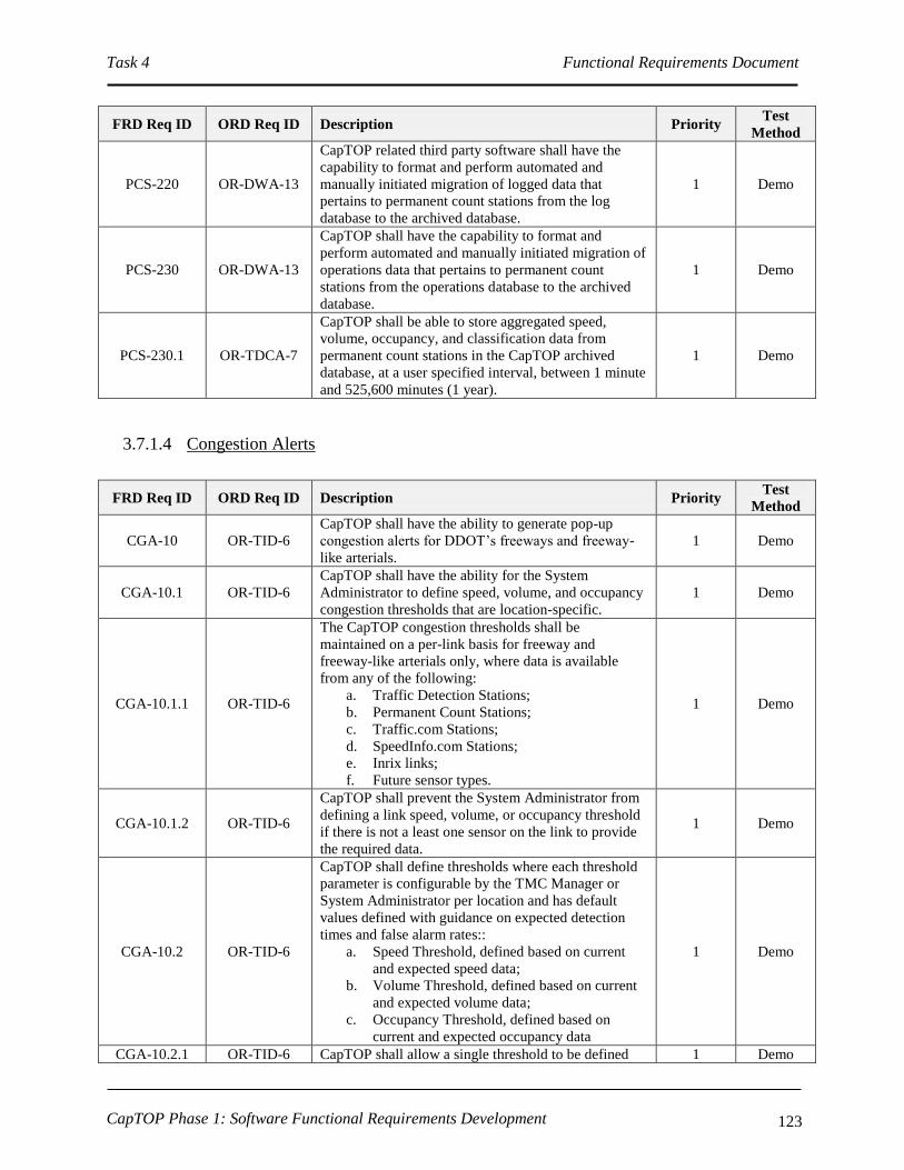
Task 4 Functional Requirements Document
CapTOP Phase 1: Software Functional Requirements Development 123
FRD Req ID ORD Req ID Description Priority Test
Method
PCS-220 OR-DWA-13
CapTOP related third party software shall have the
capability to format and perform automated and
manually initiated migration of logged data that
pertains to permanent count stations from the log
database to the archived database.
1 Demo
PCS-230 OR-DWA-13
CapTOP shall have the capability to format and
perform automated and manually initiated migration of
operations data that pertains to permanent count
stations from the operations database to the archived
database.
1 Demo
PCS-230.1 OR-TDCA-7
CapTOP shall be able to store aggregated speed,
volume, occupancy, and classification data from
permanent count stations in the CapTOP archived
database, at a user specified interval, between 1 minute
and 525,600 minutes (1 year).
1 Demo
3.7.1.4 Congestion Alerts
FRD Req ID ORD Req ID Description Priority Test
Method
CGA-10 OR-TID-6
CapTOP shall have the ability to generate pop-up
congestion alerts for DDOT’s freeways and freeway-
like arterials.
1 Demo
CGA-10.1 OR-TID-6
CapTOP shall have the ability for the System
Administrator to define speed, volume, and occupancy
congestion thresholds that are location-specific.
1 Demo
CGA-10.1.1 OR-TID-6
The CapTOP congestion thresholds shall be
maintained on a per-link basis for freeway and
freeway-like arterials only, where data is available
from any of the following:
a. Traffic Detection Stations;
b. Permanent Count Stations;
c. Traffic.com Stations;
d. SpeedInfo.com Stations;
e. Inrix links;
f. Future sensor types.
1 Demo
CGA-10.1.2 OR-TID-6
CapTOP shall prevent the System Administrator from
defining a link speed, volume, or occupancy threshold
if there is not a least one sensor on the link to provide
the required data.
1 Demo
CGA-10.2 OR-TID-6
CapTOP shall define thresholds where each threshold
parameter is configurable by the TMC Manager or
System Administrator per location and has default
values defined with guidance on expected detection
times and false alarm rates::
a. Speed Threshold, defined based on current
and expected speed data;
b. Volume Threshold, defined based on current
and expected volume data;
c. Occupancy Threshold, defined based on
current and expected occupancy data
1 Demo
CGA-10.2.1 OR-TID-6 CapTOP shall allow a single threshold to be defined 1 Demo

Task 4 Functional Requirements Document
CapTOP Phase 1: Software Functional Requirements Development 124
FRD Req ID ORD Req ID Description Priority Test
Method
that is any combination of speed, volume, and
occupancy thresholds.
CGA-10.3 OR-TID-6
The CapTOP alert that is generated when a threshold is
exceeded shall provide a pop-up alert to the operator
that must be acknowledged.
1 Demo
CGA-10.3.1 OR-TID-6,
UR-TO-14
The alert shall provide a button that says display
closest CCTV camera and when selected allows the
user to view and control the CCTV camera closest to
the area of congestion.
1 Demo
CGA-10.4 OR-TID-6
For each alert generated, CapTOP shall generate a
system event log entry (refer to INM-430*) that logs
the link-id, threshold type exceeded, current date,
current time, and current speed, volume, and
occupancy readings for that link.
1 Demo
CGA-10.5 OR-TID-6
CapTOP shall not generate an alert for a threshold
until the threshold has been exceeded a minimum of N
consecutive polling cycles, where N has a default
value of 5 cycles, and where N is a value that is
configurable by the System Administrator.
1 Demo
CGA-10.5.1 OR-TID-6
CapTOP shall not generate subsequent threshold alerts
for a link, until the congestion clears and none of the
thresholds associated with a link are exceeded for a
minimum of M minutes, where M has a default value
of 30 minutes, and where M is a value that is
configurable by the System Administrator.
1 Demo
CGA-10.6 OR-TID-6
The CapTOP congestion alert capability shall have a
global system parameter that allows the System
Administrator or TMC Manager to enable and disable
this capability.
1 Demo
CGA-10.7 OR-TID-6
The CapTOP congestion alert capability shall allow
the System Administrator or TMC Manager to enable
or disable this capability in advance based on day of
week and time of day using the CapTOP scheduler
capability (refer to GUI-350).
1 Demo
CGA-10.8 OR-TID-6
The CapTOP congestion alert capability shall allow
the System Administrator or TMC Manager to enable
weather checking to automatically enable/disable
congestion alerts during inclement weather.
1 Demo
CGA-10.8.1 OR-TID-6
If weather checking is enabled, the congestion alert
capability shall automatically obtain the current
weather status from CapTOP’s RWIS data to
determine if inclement weather (fog, snow, ice, rain,
sleet) is present.
1 Demo
CGA-10.8.2 OR-TID-6
The congestion alert capability shall disable congestion
alerts if the weather is inclement and not re-enable
until inclement weather is eliminated for a minimum of
30 minutes.
1 Demo
3.7.1.5 Traffic.Com Interface
3.7.1.5.1 Accessing the Traffic.Com Interface Subsystem

Task 4 Functional Requirements Document
CapTOP Phase 1: Software Functional Requirements Development 125
FRD Req
ID
ORD Req
ID Description Priority
Test
Method
TDC-10 OR-DOC-1
CapTOP shall allow the TMC Operator to access the
Traffic.Com interface subsystem, subject to operator privilege
level.
C Demo
TDC-10.1 OR-DOC-1
CapTOP shall allow the TMC Operator to access the
Traffic.Com interface subsystem, using the following
mechanisms:
a. Left clicking on a Traffic.Com station icon on the
map display;
b. Left clicking on the Traffic.Com interface subsystem
icon off the CapTOP toolbar;
c. Left clicking on the Traffic.Com interface subsystem
menu off the CapTOP toolbar.
1 Demo
TDC-10.2
OR-SMM-
5, OR-
DOC-1
CapTOP shall provide role-based privileges to control access
to the following, subject to the user’s privilege level:
a. Traffic.Com station events and alarms;
b. Traffic.Com station status (refer to TDC-40 and
TDC-50);
c. Traffic.Com station data (refer to TDC-40).
C Demo
TDC-20 IR-GUI-10 CapTOP shall display all Traffic.Com station icons on a
separate layer on the map-based display. 1 Demo
TDC-20.1 IR-GUI-12 CapTOP shall allow the TMC Operator to turn on and off the
Traffic.Com station layer on the map display. 1 Demo
TDC-20.2 IR-GUI-10,
IR-GUI-11
CapTOP shall allow a Traffic.Com station icon to be left
clicked on the map display by the TMC Operator and permit
access to the Traffic.Com station status window (refer to
TDC-40 and TDC-50), with no more than 2 additional clicks.
1 Demo
TDC-20.3 IR-GUI-12 The icons used for the Traffic.Com station icon layer shall be
unique from icons used in other layers. 1 Demo
TDC-30 IR-GUI-10
CapTOP shall provide the ability for the System
Administrator to add, delete, and modify Traffic.Com stations
from the CapTOP map display (also refer to GUI-200*).
C Demo
TDC-30.1 IR-GUI-10
CapTOP shall allow the System Administrator to point and
click on a location on the map display to add a new
Traffic.Com station icon using a pop-up menu.
1 Demo
TDC-30.2 IR-GUI-10
When a Traffic.Com station icon is added, CapTOP shall
prompt the System Administrator with a window to enter all
configuration data required to integrate the device.
1 Demo
TDC-30.2.1
IR-GUI-10,
OR-TDCA-
20,
OR-TDCA-
21
CapTOP shall allow the following configuration data to be
entered for each Traffic.Com station to enable the device to
become operational in the system:
a. Station Number;
b. Detector ID;
c. Description;
d. Detector Model Number;
e. Location Information;
I. Location Description;
II. Street Address;
III. Road Name;
IV. Road Direction;
V. Exit Number;
VI. Milepost;
1 Demo

Task 4 Functional Requirements Document
CapTOP Phase 1: Software Functional Requirements Development 126
FRD Req
ID
ORD Req
ID Description Priority
Test
Method
VII. Intersection/Interchange.
f. Road Classification (interstate, freeway/expressway,
principal arterial, minor arterial, collector, local);
g. Online-Offline Mode ( static – set by System
Administrator or Maintenance Technician);
h. Group Name;
i. Lane information:
I. Number of Lanes;
II. For each Lane:
i. Lane Number;
ii. Direction;
iii. Movement (turning lane, through
lane, shared lane).
j. Model Number of Sensor;
k. Protocol;
l. Link ID;
m. Polling Enabled (yes/no, defaults to yes);
n. Associated CCTV;
o. TMDD Information;
I. Horizontal Datum (WGS84, 84EGM96,
NAD83);
II. Latitude (decimal degrees);
III. Longitude (decimal degrees);
IV. Vertical Datum (WGS84);
V. Height (-127 to 127);
VI. Vertical Level (-127 to 127).
TDC -
30.2.2 IR-GUI-10
When a Traffic.Com station device icon is added, CapTOP
shall prompt the System Administrator or Maintenance
Technician with setting the device online or offline.
1 Demo
TDC-30.2.3 IR-GUI-10
If the user enters a latitude/longitude pair for the device, the
device icon location on the map shall be updated
automatically based on the coordinates specified (and not
where there user clicked to create the icon).
1 Demo
TDC-30.3 IR-GUI-10,
IR-GUI-11
CapTOP shall allow a Traffic.Com station icon to be right
clicked on the map display and permit access to the following
functions by the System Administrator or Maintenance
Technician, with no more than 2 additional clicks:
a. setting the online-offline mode;
b. entering, deleting, or modifying configuration
information;
c. allowing the device icon to be relocated on the map
display;
d. displaying the Traffic.Com station status window;
e. allowing the device icon to be deleted.
1 Demo
TDC-30.4 OR-IM-4
CapTOP shall strictly enforce the use of pull-down menus,
radio buttons, or selection boxes when any of the following
fields are entered by the user:
a. Street Address/Block;
b. Road Name;
1 Demo

Task 4 Functional Requirements Document
CapTOP Phase 1: Software Functional Requirements Development 127
FRD Req
ID
ORD Req
ID Description Priority
Test
Method
c. Road Direction;
d. Exit Number;
e. Milepost;
f. Intersection/Interchange;
g. Road Classification (interstate, freeway/expressway,
principal arterial, minor arterial, collector, local);
h. Online-Offline Mode (online/offline);
i. Protocol;
j. Link ID;
k. Polling Enabled (yes/no, defaults to yes);
l. Associated CCTV.
TDC-30.4.1 OR-IM-4 CapTOP shall restrict the use of free-form text entry on the
fields identified above. 1 Demo
TDC-30.4.2 OR-IM-4
CapTOP shall allow the user to type the 1st 3 characters in
each field and the system will provide a filtered list of
selections for that field that begin with the 1st 3 characters
typed by the user.
2 Demo
TDC-30.4.3 OR-IM-4 CapTOP shall allow the user to select “Other” and enter in
free form text when a desired entry cannot be found in the list. 1 Demo
3.7.1.5.2 Monitoring Traffic.Com Station Status
FRD Req ID ORD Req ID Description Priority Test
Method
TDC-40
OR-DOC-10,
IR-GUI-14,
IR-GUI-16,
OR-TDCA-1,
UR-TO-25,
OR-TDCA-15,
OR-C2F-1
CapTOP shall allow the TMC Operator to retrieve and
display the following operational status and
operational data, on a real-time basis, for any
Traffic.Com station, subject to operator privilege level:
a. Station number;
b. Detector ID;
c. Road classification;
d. Online-offline mode ( static – set by System
Administrator or Maintenance Technician);
e. Traffic.com server status (OK, failed);
f. Detector status (OK, failed);
g. Average speed, volume, and occupancy by
lane by direction per last aggregation interval;
h. Last contact (date/time stamp on data);
i. Last Traffic.com server status change
(date/time).
C Demo
TDC-40.1 OR-DOC-1
CapTOP shall use data from the following sources to
determine operational status:
a. data reported from the Traffic.com server;
b. data gained by CapTOP in attempts to
communicate with the Traffic.com server;
c. online/offline information entered manually
by authorized CapTOP users.
C Demo
TDC-50
SR-SYS-2,
IR-GUI-36,
IR-GUI-26
CapTOP shall allow privileged users to simultaneously
view Traffic.Com station status, which is refreshed
automatically by the system based on the polling
interval, using the following methods:
C Demo

Task 4 Functional Requirements Document
CapTOP Phase 1: Software Functional Requirements Development 128
FRD Req ID ORD Req ID Description Priority Test
Method
a. Color coded icons on the map display;
b. Via the Traffic.Com station status window
which lists all Traffic.Com stations, the
station number, Detector ID, location,
direction, online-offline mode, Traffic.com
server status, and detector status.
TDC-50.1 IR-GUI-28,
IR-GUI-26
CapTOP shall use the following colors for device icon
states:
a. Black = device failure, but online in CapTOP;
b. Orange = communication failure;
c. Gray = offline.
d. Maroon = online and speed is between 0%
and 25% of free flow speed;
e. Red = online and speed is between 25% and
50% of free flow speed;
f. Yellow = online and speed is between 50%
and 75% of free flow;
g. Light Green = online and speed is between
75% and 90% of free flow speed;
h. Dark Green = online and speed is > 90% of
free flow speed.
Also refer to GUI-150* requirements for an
understanding of how traffic condition data is
displayed on a per link basis.
C Demo
TDC-50.1.1 IR-GUI-28,
IR-GUI-26
CapTOP shall use the following rules for device icon
states:
c. If the device is online but in communication
failure, the device icon color should be that of
a device with a communication failure;
d. In order for the device icon to be red, maroon,
yellow, light green, or dark green, the device
must be both online and have OK
communication.
C Demo
TDC-50.2 IR-GUI-31,
IR-GUI-29
The refresh rate for icon status and for the data in the
status window shall be configurable and based upon
the polling rate.
1 Demo
TDC-50.3 IR-GUI-31
CapTOP shall allow the user to obtain summary status
information (refer to TDC-40 for the list of fields) by
hovering over a Traffic.com icon.
1 Demo
TDC-50.4 IR-GUI-29
CapTOP shall allow the user to select on any
Traffic.Com station in the Traffic.com status window
(refer to TDC-50 item b) and view all details (full
status, configuration information) pertaining to that
Traffic.Com station.
1 Demo
TDC-60
SR-SYS-2,
IR-GUI-31,
IR-GUI-32
CapTOP shall provide a menu option to search for a
Traffic.Com station by the following methods:
a. station number;
b. detector ID;
c. group name;
d. street name;
e. geographical address;
f. intersection/interchange.
C Demo

Task 4 Functional Requirements Document
CapTOP Phase 1: Software Functional Requirements Development 129
FRD Req ID ORD Req ID Description Priority Test
Method
TDC-60.1 SR-SYS-2,
IR-GUI-31
CapTOP shall allow the TMC Operator to search for
Traffic.Com stations using a rubber-band style box on
the map display to search an area.
C Demo
TDC-60.2 SR-SYS-2,
IR-GUI-31
The result of each search shall be a list of Traffic.Com
stations that are sorted, by default, by station number. 1 Demo
TDC-60.3
SR-SYS-2,
IR-GUI-31,
OR-TDCA-18
The result of each search shall be a list of Traffic.Com
stations sortable by station number, detector ID, group
name, street name, geographical address, and
intersection/interchange.
1 Demo
TDC-70 IR-GUI-14
CapTOP shall provide a monitoring interface to
Traffic.com’s existing remote server through
CapTOP’s new Traffic Data Server for monitoring the
Traffic.com stations.
Refer to TDA-10* for more information.
C Demo
TDC-70.1 OR-DOC-3,
OR-TDCA-6
CapTOP’s Traffic Data Server (developed by others,
or optionally, by the CapTOP developer) shall
interface with the Traffic.Com remote server in
accordance with the Traffic.com XML Format
document, dated January 2007.
1 Demo
TDC-70.1.1
OR-DOC-2,
OR-DOC-3,
IR-GUI-29
CapTOP shall support a polling interval range from 0
to 99999 seconds, where zero indicates no polling. 1 Demo
TDC-70.1.1.1
OR-DOC-2,
OR-DOC-3,
IR-GUI-29
The default polling interval shall be once every 3
minutes. 1 Demo
TDC-70.2 IR-GUI-14
CapTOP shall be able to request Traffic.Com station
status and obtain status response data through the
Traffic Data Server.
1 Demo
TDC-70.3 IR-GUI-14 CapTOP shall prohibit Traffic.Com detector changes
through this interface. 1 Demo
TDC-80
OR-C2F-3,
OR-C2F-4,
OR-DWA-13,
OR-TDCA-16
CapTOP shall be able to store all Traffic.Com stations
operational data (refer to TDC-40) in the CapTOP
operations database for each polling cycle.
1 Demo
TDC-90 OR-TDCA-3
CapTOP shall store the speed, volume, and occupancy
data by road name, interchange, direction, detector ID,
and station number.
1 Demo
3.7.1.5.3 Traffic.Com Station Reports
FRD Req ID ORD Req ID Description Priority Test
Method
TDC-100 OR-TDCA-4,
OR-TDCA-17
CapTOP shall be able to display and print data from
Traffic.Com stations in both tabular and graphical
formats.
2 Demo
TDC-110
SR-SYS-22,
SR-SYS-36,
OR-DOC-4,
IR-GUI-8
CapTOP shall be able to automatically generate real-
time tabular reports that show the real-time operational
status and operational data of all Traffic.Com stations.
2 Demo

Task 4 Functional Requirements Document
CapTOP Phase 1: Software Functional Requirements Development 130
FRD Req ID ORD Req ID Description Priority Test
Method
TDC-110.1
SR-SYS-22,
SR-SYS-36,
OR-DOC-4,
IR-GUI-8
CapTOP shall provide the following information in the
Traffic.Com station status summary report:
a. Station number;
b. Detector ID;
c. Location;
d. Road Direction;
e. Number of lanes;
f. Online-offline mode;
g. Detector status (OK, failed);
h. Traffic.com server status (OK, failed).
2 Demo
TDC-110.2
SR-SYS-22,
SR-SYS-36,
OR-DOC-4,
IR-GUI-8
CapTOP shall provide the following information in the
Traffic.Com station extended status report:
a. Station number;
b. Detector ID;
c. Location;
d. Road Direction;
e. Road classification;
f. Online-offline mode ( static – set by System
Administrator or Maintenance Technician);
g. Traffic.com server status (OK, failed);
h. Detector status (OK, failed);
i. Number of lanes;
j. Average speed, volume, and occupancy by
lane by direction per last aggregation interval;
k. Last contact (date/time stamp on data);
l. Last Traffic.com server status change
(date/time).
2 Demo
TDC-110.2.1
SR-SYS-22,
SR-SYS-36,
OR-DOC-4,
IR-GUI-8
CapTOP shall be able to display graphical reports in a
Microsoft Excel-like 2-dimensional or 3-dimensional
format using data in the extended status report.
2 Demo
TDC-110.3
SR-SYS-22,
SR-SYS-36,
OR-DOC-4,
IR-GUI-8
CapTOP shall be able to provide a full device
configuration report for a user entered Station number
or Detector ID.
2 Demo
TDC-120 OR-DWA-7,
OR-DWA-5
CapTOP shall be able to produce the following
performance reports for evaluating the performance of
Traffic.Com stations, using data in the CapTOP
operations and archived databases:
a. Number of times a Traffic.com station
transitioned from online to offline over a
specified time period;
b. Number of times a Traffic.com detector ID
status transitioned from OK to failed over a
specified time period;
c. Number of times a Traffic.com server status
transitioned from OK to failed over a
specified time period;
d. A report showing missing data from each
traffic detection station.
2 Demo

Task 4 Functional Requirements Document
CapTOP Phase 1: Software Functional Requirements Development 131
FRD Req ID ORD Req ID Description Priority Test
Method
TDC-130 OR-DWA-7,
OW-DWA-5
CapTOP shall be able to produce a Traffic.Com station
report by allowing the user to specify a station number,
detector ID, starting date/time, ending date time, and a
reporting interval (5 minute, 15 minute, hourly, daily,
monthly, seasonal, quarterly, bi-annual, annual).
2 Demo
TDC-140 OR-DWA-7,
OW-DWA-5
CapTOP shall be able to produce the following reports
by allowing the user to specify a station number,
detector ID, starting date/time, ending date time, and a
reporting interval (5 minute, 15 minute, hourly, daily,
monthly, seasonal, quarterly, bi-annual, annual):
a. Speed Peak Period Average;
b. Speed Daily Average;
c. Speed Weekly Average;
d. Speed Monthly Average;
e. Volume Peak Period Average;
f. Volume Daily Average;
g. Volume Weekly Average;
h. Volume Monthly Average;
i. Occupancy Peak Period Average;
j. Occupancy Daily Average;
k. Occupancy Weekly Average;
l. Occupancy Monthly Average.
2 Demo
TDC-150 OR-DWA-7,
OW-DWA-5
CapTOP shall allow the operator to search for data by
specifying any of the following:
a. Station number;
b. Detector ID;
c. Description;
d. Location;
e. Road Direction;
f. Road classification;
g. Group name;
h. Starting date/time;
i. Ending date/time;
j. Type of data (speed, volume, occupancy);
k. Number of lanes;
l. Lane number;
m. User specified speed, volume or occupancy;
n. Reporting interval;
o. Lane type (turning movement, non-turning
movement).
2 Demo
TDC-160 OR-DWA-7,
OW-DWA-5
CapTOP shall support an ad-hoc report generation
capability that allows the user to build and specify
their own queries based on data stored in Traffic.com-
related databases.
2 Demo
TDC-160.1 OR-TDCA-2
CapTOP shall be able to aggregate speed, volume, and
occupancy data on-the-fly from Traffic.Com stations
in the CapTOP operations database, at a user specified
interval, between 1 minute and 525,600 minutes (1
year).
1 Demo
TDC-160.2 OR-TDCA-2
CapTOP shall be able to store aggregated speed,
volume, and occupancy data from Traffic.Com stations
in a Microsoft Excel format, at a user specified
interval, between 1 minute and 525,600 minutes (1
year).
1 Demo
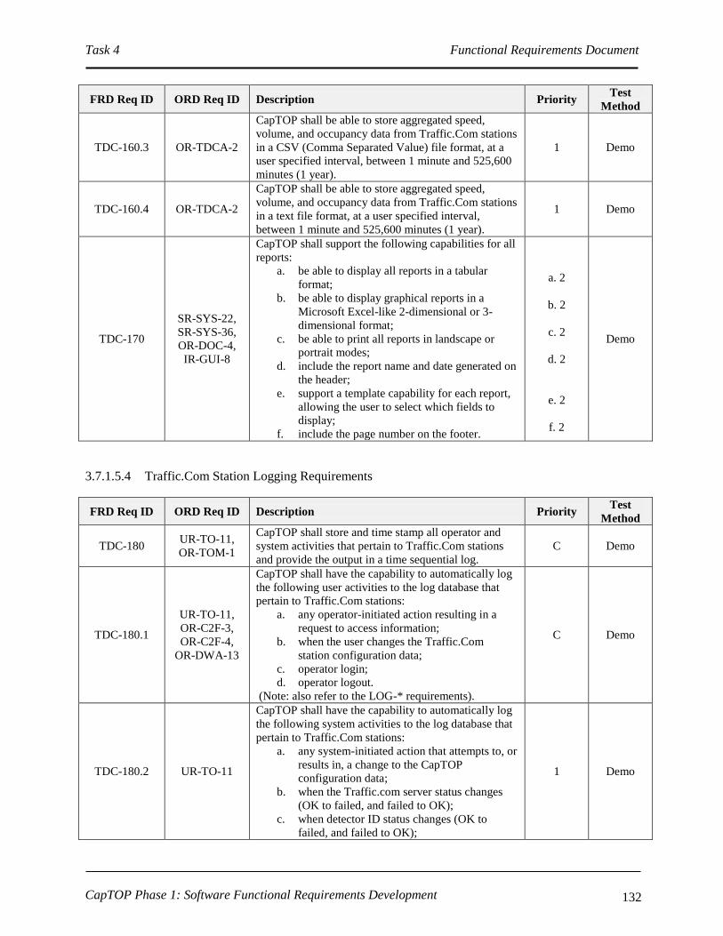
Task 4 Functional Requirements Document
CapTOP Phase 1: Software Functional Requirements Development 132
FRD Req ID ORD Req ID Description Priority Test
Method
TDC-160.3 OR-TDCA-2
CapTOP shall be able to store aggregated speed,
volume, and occupancy data from Traffic.Com stations
in a CSV (Comma Separated Value) file format, at a
user specified interval, between 1 minute and 525,600
minutes (1 year).
1 Demo
TDC-160.4 OR-TDCA-2
CapTOP shall be able to store aggregated speed,
volume, and occupancy data from Traffic.Com stations
in a text file format, at a user specified interval,
between 1 minute and 525,600 minutes (1 year).
1 Demo
TDC-170
SR-SYS-22,
SR-SYS-36,
OR-DOC-4,
IR-GUI-8
CapTOP shall support the following capabilities for all
reports:
a. be able to display all reports in a tabular
format;
b. be able to display graphical reports in a
Microsoft Excel-like 2-dimensional or 3-
dimensional format;
c. be able to print all reports in landscape or
portrait modes;
d. include the report name and date generated on
the header;
e. support a template capability for each report,
allowing the user to select which fields to
display;
f. include the page number on the footer.
a. 2
b. 2
c. 2
d. 2
e. 2
f. 2
Demo
3.7.1.5.4 Traffic.Com Station Logging Requirements
FRD Req ID ORD Req ID Description Priority Test
Method
TDC-180 UR-TO-11,
OR-TOM-1
CapTOP shall store and time stamp all operator and
system activities that pertain to Traffic.Com stations
and provide the output in a time sequential log.
C Demo
TDC-180.1
UR-TO-11,
OR-C2F-3,
OR-C2F-4,
OR-DWA-13
CapTOP shall have the capability to automatically log
the following user activities to the log database that
pertain to Traffic.Com stations:
a. any operator-initiated action resulting in a
request to access information;
b. when the user changes the Traffic.Com
station configuration data;
c. operator login;
d. operator logout.
(Note: also refer to the LOG-* requirements).
C Demo
TDC-180.2 UR-TO-11
CapTOP shall have the capability to automatically log
the following system activities to the log database that
pertain to Traffic.Com stations:
a. any system-initiated action that attempts to, or
results in, a change to the CapTOP
configuration data;
b. when the Traffic.com server status changes
(OK to failed, and failed to OK);
c. when detector ID status changes (OK to
failed, and failed to OK);
1 Demo

Task 4 Functional Requirements Document
CapTOP Phase 1: Software Functional Requirements Development 133
FRD Req ID ORD Req ID Description Priority Test
Method
d. changes in online-offline mode;
e. software application login;
f. software application logout;
g. database login;
h. database logout.
(Note: also refer to the LOG-* requirements).
TDC-180.3 UR-TO-11 CapTOP shall provide a window to display all logged
system and user activities for Traffic.Com stations. 1 Demo
TDC-180.4 UR-TO-11
CapTOP shall assign and store one of the following
action types when logging all Traffic.Com station
activities:
a. operator input;
b. operator informational message;
c. operator error;
d. system warning;
e. system error;
f. system information message;
g. software application warning;
h. software application error;
i. software application information message.
1 Demo
TDC-180.5 UR-TO-11
For log entries triggered by user actions, CapTOP shall
log the following:
a. Username;
b. Date stamp;
c. Time stamp;
d. Workstation ID;
e. Workstation IP address;
f. Action type;
g. Description of action (include the device ID,
description of action, and summary status of
device).
1 Demo
TDC-180.6 UR-TO-11
For log entries generated by the CapTOP applications,
CapTOP shall log the following:
a. Application name;
b. Date stamp;
c. Time stamp;
d. Action type;
e. Description of action.
1 Demo
TDC-180.7 UR-TO-11 CapTOP shall make all log entries read-only,
changeable by only the System Administrator. 1 Demo
TDC-190 OR-DWA-5
CapTOP shall have the capability to query and retrieve
all operator actions/commands that pertain to
Traffic.Com stations from the log by filtering on the
following:
a. Workstation ID;
b. Workstation IP address;
c. Username;
d. Date stamp;
e. Time stamp;
f. Action type.
1 Demo

Task 4 Functional Requirements Document
CapTOP Phase 1: Software Functional Requirements Development 134
FRD Req ID ORD Req ID Description Priority Test
Method
TDC-200 UR-TO-11,
OR-DDM-16
CapTOP shall be capable of generating a system alert
for the following:
a. changes in Traffic.com server status (OK to
failed, and failed to OK);
b. changes in online-offline mode;
c. changes to Traffic.Com station configuration
data;
d. when a detector ID status changes to out-of-
service.
1 Demo
3.7.1.5.5 Traffic.Com Station Archiving Requirements
FRD Req ID ORD Req ID Description Priority Test
Method
TDC-210 OR-DWA-13
CapTOP or related third party software shall have the
capability to format and perform automated and
manually initiated migration of logged data that
pertains to Traffic.Com stations from the log database
to the archived database.
1 Demo
TDC-220 OR-DWA-13
CapTOP or related third party software shall have the
capability to format and perform automated and
manually initiated migration of operations data that
pertains to Traffic.Com stations from the operations
database to the archived database.
1 Demo
TDC-220.1 OR-TDCA-2
CapTOP shall be able to store aggregated speed,
volume, and occupancy data from Traffic.Com stations
in the CapTOP archived database, at a user specified
interval, between 1 minute and 525,600 minutes (1
year).
1 Demo
3.7.1.6 SpeedInfo Interface
3.7.1.6.1 Accessing the SpeedInfo Interface Subsystem
FRD Req
ID
ORD Req
ID Description Priority
Test
Method
SPD-10 OR-DOC-1
CapTOP shall allow the TMC Operator to access the
SpeedInfo interface subsystem, subject to operator privilege
level.
C Demo
SPD-10.1 OR-DOC-1
CapTOP shall allow the TMC Operator to access the
SpeedInfo interface subsystem, using the following
mechanisms:
a. Left clicking on a SpeedInfo station icon on the map
display;
b. Left clicking on the SpeedInfo interface subsystem
icon off the CapTOP toolbar;
c. Left clicking on the SpeedInfo interface subsystem
menu off the CapTOP toolbar.
1 Demo

Task 4 Functional Requirements Document
CapTOP Phase 1: Software Functional Requirements Development 135
FRD Req
ID
ORD Req
ID Description Priority
Test
Method
SPD-10.2 OR-SMM-5,
OR-DOC-1
CapTOP shall provide role-based privileges to control access
to the following, subject to the user’s privilege level:
a. SpeedInfo station events and alarms;
b. SpeedInfo station status (refer to SPD-40 and SPD-
50);
c. SpeedInfo station data (refer to SPD-40).
C Demo
SPD-20 IR-GUI-10 CapTOP shall display all SpeedInfo station icons on a
separate layer on the map-based display. 1 Demo
SPD-20.1 IR-GUI-12 CapTOP shall allow the TMC Operator to turn on and off the
SpeedInfo station layer on the map display. 1 Demo
SPD-20.2 IR-GUI-10,
IR-GUI-11
CapTOP shall allow a SpeedInfo station icon to be left
clicked on the map display by the TMC Operator and permit
access to the SpeedInfo station status window (refer to SPD-
40 and SPD-50), with no more than 2 additional clicks.
1 Demo
SPD-20.3 IR-GUI-12 The icons used for the SpeedInfo station icon layer shall be
unique from icons used in other layers. 1 Demo
SPD-30 IR-GUI-10
CapTOP shall provide the ability for the System
Administrator to add, delete, and modify SpeedInfo stations
from the CapTOP map display (also refer to GUI-200*).
C Demo
SPD-30.1 IR-GUI-10
CapTOP shall allow the System Administrator to point and
click on a location on the map display to add a new
SpeedInfo station icon using a pop-up menu.
1 Demo
SPD-30.2 IR-GUI-10
When a SpeedInfo station icon is added, CapTOP shall
prompt the System Administrator with a window to enter all
configuration data required to integrate the device.
1 Demo
SPD-30.2.1
IR-GUI-10,
OR-TDCA-
20,
OR-TDCA-
21
CapTOP shall allow the following configuration data to be
entered for each SpeedInfo station to enable the device to
become operational in the system:
a. Station Number;
b. Detector ID;
c. Description;
d. Detector Model Number;
e. Location Information;
I. Location Description;
II. Street Address;
III. Road Name;
IV. Road Direction;
V. Exit Number;
VI. Milepost;
VII. Intersection/Interchange.
f. Road Classification (interstate, freeway/expressway,
principal arterial, minor arterial, collector, local);
g. Online-Offline Mode ( static – set by System
Administrator or Maintenance Technician);
h. Group Name;
i. Lane information:
I. Number of Lanes;
II. For each Lane:
i. Direction;
j. Model Number of Sensor;
1 Demo

Task 4 Functional Requirements Document
CapTOP Phase 1: Software Functional Requirements Development 136
FRD Req
ID
ORD Req
ID Description Priority
Test
Method
k. Protocol;
l. Link ID;
m. Polling Enabled (yes/no, defaults to yes);
n. Associated CCTV;
o. TMDD Information;
I. Horizontal Datum (WGS84, 84EGM96,
NAD83);
II. Latitude (decimal degrees);
III. Longitude (decimal degrees);
IV. Vertical Datum (WGS84);
V. Height (-127 to 127);
VI. Vertical Level (-127 to 127).
SPD-30.2.2 IR-GUI-10
When a SpeedInfo station device icon is added, CapTOP
shall prompt the System Administrator or Maintenance
Technician with setting the device online or offline.
1 Demo
SPD-30.2.3 IR-GUI-10
If the user enters a latitude/longitude pair for the device, the
device icon location on the map shall be updated
automatically based on the coordinates specified (and not
where there user clicked to create the icon).
1 Demo
SPD-30.3 IR-GUI-10,
IR-GUI-11
CapTOP shall allow a SpeedInfo station icon to be right
clicked on the map display and permit access to the following
functions by the System Administrator or Maintenance
Technician, with no more than 2 additional clicks:
a. setting the online-offline mode;
b. entering, deleting, or modifying configuration
information;
c. allowing the device icon to be relocated on the map
display;
d. displaying the SpeedInfo station status window;
e. allowing the device icon to be deleted.
1 Demo
SPD-30.4 OR-IM-4
CapTOP shall strictly enforce the use of pull-down menus,
radio buttons, or selection boxes when any of the following
fields are entered by the user:
a. Street Address/Block;
b. Road Name;
c. Road Direction;
d. Exit Number;
e. Milepost;
f. Intersection/Interchange;
g. Road Classification (interstate, freeway/expressway,
principal arterial, minor arterial, collector, local);
h. Online-Offline Mode (online/offline);
i. Protocol;
j. Link ID;
k. Polling Enabled (yes/no, defaults to yes);
l. Associated CCTV.
1 Demo
SPD-30.4.1 OR-IM-4 CapTOP shall restrict the use of free-form text entry on the
fields identified above. 1 Demo
SPD-30.4.2 OR-IM-4 CapTOP shall allow the user to type the 1
st 3 characters in
each field and the system will provide a filtered list of 2 Demo

Task 4 Functional Requirements Document
CapTOP Phase 1: Software Functional Requirements Development 137
FRD Req
ID
ORD Req
ID Description Priority
Test
Method
selections for that field that begin with the 1st 3 characters
typed by the user.
SPD-30.4.3 OR-IM-4
CapTOP shall allow the user to select “Other” and enter in
free form text when a desired entry cannot be found in the
list.
1 Demo
3.7.1.6.2 Monitoring SpeedInfo Station Status
FRD Req ID ORD Req ID Description Priority Test
Method
SPD-40
OR-DOC-10,
IR-GUI-14,
IR-GUI-16,
OR-TDCA-1,
UR-TO-25,
OR-TDCA-11,
OR-C2F-1
CapTOP shall allow the TMC Operator to retrieve and
display the following operational status and
operational data, on a real-time basis, for any
SpeedInfo station, subject to operator privilege level:
a. Station number;
b. Detector ID;
c. Road classification;
d. Online-offline mode ( static – set by System
Administrator or Maintenance Technician);
e. SpeedInfo server status (OK, failed);
f. Detector status (OK, out-of-service);
g. Average speed by direction per last
aggregation interval;
h. Last contact (date/time stamp on data);
i. Last SpeedInfo server status change
(date/time).
C Demo
SPD-40.1 OR-DOC-1
CapTOP shall use data from the following sources to
determine operational status:
a. data reported from the SpeedInfo server;
b. data gained by CapTOP in attempts to
communicate with the SpeedInfo server;
c. online/offline information entered manually
by authorized CapTOP users.
C Demo
SPD-50
SR-SYS-2,
IR-GUI-36,
IR-GUI-26
CapTOP shall allow privileged users to simultaneously
view SpeedInfo station status, which is refreshed
automatically by the system based on the polling
interval, using the following methods:
a. Color coded icons on the map display;
b. Via the SpeedInfo station status window
which lists all SpeedInfo stations, the station
number, Detector ID, location, direction,
online-offline mode, SpeedInfo server status,
and Detector status.
C Demo

Task 4 Functional Requirements Document
CapTOP Phase 1: Software Functional Requirements Development 138
FRD Req ID ORD Req ID Description Priority Test
Method
SPD-50.1 IR-GUI-28,
IR-GUI-26
CapTOP shall use the following colors for device icon
states:
a. Black = out-of-service by SpeedInfo, but
online in CapTOP;
b. Orange = communication failure;
c. Gray = offline.
d. Maroon = online and speed is between 0%
and 25% of free flow speed;
e. Red = online and speed is between 25% and
50% of free flow speed;
f. Yellow = online and speed is between 50%
and 75% of free flow;
g. Light Green = online and speed is between
75% and 90% of free flow speed;
h. Dark Green = online and speed is > 90% of
free flow speed.
Also refer to GUI-150* requirements for an
understanding of how traffic condition data is
displayed on a per link basis.
C Demo
SPD-50.1.1 IR-GUI-28,
IR-GUI-26
CapTOP shall use the following rules for device icon
states:
e. If the device is online but in communication
failure, the device icon color should be that of
a device with a communication failure;
f. In order for the device icon to be red, maroon,
yellow, light green, or dark green, the device
must be both online and have OK
communication.
C Demo
SPD-50.2 IR-GUI-31,
IR-GUI-29
The refresh rate for icon status and for the data in the
status window shall be configurable and based upon
the polling rate.
1 Demo
SPD-50.3 IR-GUI-31
CapTOP shall allow the user to obtain summary status
information (refer to SPD-40 for the list of fields) by
hovering over a SpeedInfo icon.
1 Demo
SPD-50.4 IR-GUI-29
CapTOP shall allow the user to select on any
SpeedInfo station in the SpeedInfo status window
(refer to SPD-50 item b) and view all details (full
status, configuration information) pertaining to that
SpeedInfo station.
1 Demo
SPD-60
SR-SYS-2,
IR-GUI-31,
IR-GUI-32
CapTOP shall provide a menu option to search for a
SpeedInfo station by the following methods:
a. station number;
b. detector ID;
c. group name;
d. street name;
e. geographical address;
f. intersection/interchange.
C Demo
SPD-60.1 SR-SYS-2,
IR-GUI-31
CapTOP shall allow the TMC Operator to search for
SpeedInfo stations using a rubber-band style box on
the map display to search an area.
C Demo

Task 4 Functional Requirements Document
CapTOP Phase 1: Software Functional Requirements Development 139
FRD Req ID ORD Req ID Description Priority Test
Method
SPD-60.2 SR-SYS-2,
IR-GUI-31
The result of each search shall be a list of SpeedInfo
stations that are sorted, by default, by station number. 1 Demo
SPD-60.3
SR-SYS-2,
IR-GUI-31,
OR-TDCA-14
The result of each search shall be a list of SpeedInfo
stations sortable by station number, detector ID, group
name, street name, geographical address, and
intersection/interchange.
1 Demo
SPD-70
IR-GUI-14,
OR-TDCA-11
CapTOP shall provide a monitoring interface to
SpeedInfo’s existing remote server (in California)
through CapTOP’s new Traffic Data Server for
monitoring the SpeedInfo stations.
Refer to TDA-10* for more information.
C Demo
SPD-70.1 OR-DOC-3,
OR-TDCA-6
CapTOP’s Traffic Data Server (developed by others,
or optionally, by the CapTOP developer) shall
interface with the SpeedInfo remote server in
accordance with the SpeedInfo database schema and
the SpeedInfo XML-based “listener” connection to
access SpeedInfo station data.
1 Demo
SPD-70.1.1 OR-DOC-3,
OR-TDCA-6
CapTOP shall obtain data in accordance with
SpeedInfo’s XML interface to access the following
DDOT-relevant portions of the SpeedInfo database
schema:
a. Station number;
b. Detector ID;
c. Street name;
d. Direction;
e. Long/Lat;
f. Speed;
g. Date/time;
h. Communication Status (OK, out-of-service).
1 Demo
SPD-70.1.2
OR-DOC-2,
OR-DOC-3,
IR-GUI-29
CapTOP shall support a polling interval range from 0
to 99999 seconds, where zero indicates no polling. 1 Demo
SPD-70.1.2.1
OR-DOC-2,
OR-DOC-3,
IR-GUI-29
The default polling interval shall be once every 5
minutes. 1 Demo
SPD-70.2 IR-GUI-14
CapTOP shall be able to request SpeedInfo station
status and obtain status response data through the
Traffic Data Server.
1 Demo
SPD-70.3 IR-GUI-14 CapTOP shall prohibit SpeedInfo detector changes
through this interface. 1 Demo
SPD-80
OR-C2F-3,
OR-C2F-4,
OR-DWA-13.
OR-TDCA-12
CapTOP shall be able to store all SpeedInfo station
operational data (refer to SPD-40) in the CapTOP
operations database for each polling cycle.
1 Demo
SPD-90 OR-TDCA-3
CapTOP shall store the station speed data by road
name, interchange, direction, detector ID, and station
number.
1 Demo
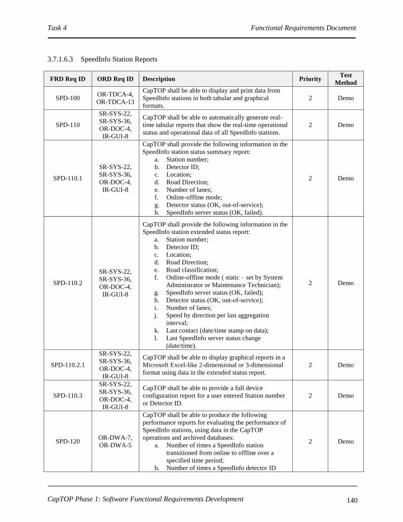
Task 4 Functional Requirements Document
CapTOP Phase 1: Software Functional Requirements Development 140
3.7.1.6.3 SpeedInfo Station Reports
FRD Req ID ORD Req ID Description Priority Test
Method
SPD-100 OR-TDCA-4,
OR-TDCA-13
CapTOP shall be able to display and print data from
SpeedInfo stations in both tabular and graphical
formats.
2 Demo
SPD-110
SR-SYS-22,
SR-SYS-36,
OR-DOC-4,
IR-GUI-8
CapTOP shall be able to automatically generate real-
time tabular reports that show the real-time operational
status and operational data of all SpeedInfo stations.
2 Demo
SPD-110.1
SR-SYS-22,
SR-SYS-36,
OR-DOC-4,
IR-GUI-8
CapTOP shall provide the following information in the
SpeedInfo station status summary report:
a. Station number;
b. Detector ID;
c. Location;
d. Road Direction;
e. Number of lanes;
f. Online-offline mode;
g. Detector status (OK, out-of-service);
h. SpeedInfo server status (OK, failed).
2 Demo
SPD-110.2
SR-SYS-22,
SR-SYS-36,
OR-DOC-4,
IR-GUI-8
CapTOP shall provide the following information in the
SpeedInfo station extended status report:
a. Station number;
b. Detector ID;
c. Location;
d. Road Direction;
e. Road classification;
f. Online-offline mode ( static – set by System
Administrator or Maintenance Technician);
g. SpeedInfo server status (OK, failed);
h. Detector status (OK, out-of-service);
i. Number of lanes;
j. Speed by direction per last aggregation
interval;
k. Last contact (date/time stamp on data);
l. Last SpeedInfo server status change
(date/time).
2 Demo
SPD-110.2.1
SR-SYS-22,
SR-SYS-36,
OR-DOC-4,
IR-GUI-8
CapTOP shall be able to display graphical reports in a
Microsoft Excel-like 2-dimensional or 3-dimensional
format using data in the extended status report.
2 Demo
SPD-110.3
SR-SYS-22,
SR-SYS-36,
OR-DOC-4,
IR-GUI-8
CapTOP shall be able to provide a full device
configuration report for a user entered Station number
or Detector ID.
2 Demo
SPD-120 OR-DWA-7,
OR-DWA-5
CapTOP shall be able to produce the following
performance reports for evaluating the performance of
SpeedInfo stations, using data in the CapTOP
operations and archived databases:
a. Number of times a SpeedInfo station
transitioned from online to offline over a
specified time period;
b. Number of times a SpeedInfo detector ID
2 Demo

Task 4 Functional Requirements Document
CapTOP Phase 1: Software Functional Requirements Development 141
FRD Req ID ORD Req ID Description Priority Test
Method
status transitioned from OK to out-of-service
over a specified time period;
c. Number of times a SpeedInfo server status
transitioned from OK to failed over a
specified time period;
d. A report showing missing data from each
traffic detection station.
SPD-130
OR-DWA-7,
OW-DWA-5,
OR-TDCA-13
CapTOP shall be able to produce a SpeedInfo station
report by allowing the user to specify a station number,
detector ID, starting date/time, ending date time, and a
reporting interval (5 minute, 15 minute, hourly, daily,
monthly, seasonal, quarterly, bi-annual, annual).
2 Demo
SPD-140 OR-DWA-7,
OW-DWA-5
CapTOP shall be able to produce the following reports
by allowing the user to specify a station number,
detector ID, starting date/time, ending date time, and a
reporting interval (5 minute, 15 minute, hourly, daily,
monthly, seasonal, quarterly, bi-annual, annual):
a. Speed Peak Period Average;
b. Speed Daily Average;
c. Speed Weekly Average;
d. Speed Monthly Average.
2 Demo
SPD-150 OR-DWA-7,
OW-DWA-5
CapTOP shall allow the operator to search for data by
specifying any of the following:
a. Station number;
b. Detector ID;
c. Description;
d. Location;
e. Road Direction;
f. Road classification;
g. Group name;
h. Starting date/time;
i. Ending date/time;
j. Type of data (speed);
k. Number of lanes;
l. Lane number;
m. User specified speed;
n. Reporting interval;
o. Lane type (turning movement, non-turning
movement).
2 Demo
SPD-160 OR-DWA-7,
OW-DWA-5
CapTOP shall support an ad-hoc report generation
capability that allows the user to build and specify
their own queries based on data stored in SpeedInfo-
related databases.
2 Demo
SPD-160.1 OR-TDCA-2
CapTOP shall be able to aggregate speed data on-the-
fly from SpeedInfo stations in the CapTOP operations
database, at a user specified interval, between 1 minute
and 525,600 minutes (1 year).
1 Demo
SPD-160.2 OR-TDCA-2
CapTOP shall be able to store aggregated speed data
from SpeedInfo stations in a Microsoft Excel format,
at a user specified interval, between 1 minute and
525,600 minutes (1 year).
1 Demo
SPD-160.3 OR-TDCA-2 CapTOP shall be able to store aggregated speed data
from SpeedInfo stations in a CSV (Comma Separated 1 Demo
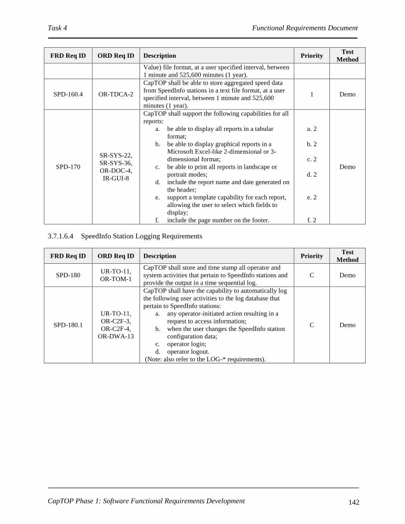
Task 4 Functional Requirements Document
CapTOP Phase 1: Software Functional Requirements Development 142
FRD Req ID ORD Req ID Description Priority Test
Method
Value) file format, at a user specified interval, between
1 minute and 525,600 minutes (1 year).
SPD-160.4 OR-TDCA-2
CapTOP shall be able to store aggregated speed data
from SpeedInfo stations in a text file format, at a user
specified interval, between 1 minute and 525,600
minutes (1 year).
1 Demo
SPD-170
SR-SYS-22,
SR-SYS-36,
OR-DOC-4,
IR-GUI-8
CapTOP shall support the following capabilities for all
reports:
a. be able to display all reports in a tabular
format;
b. be able to display graphical reports in a
Microsoft Excel-like 2-dimensional or 3-
dimensional format;
c. be able to print all reports in landscape or
portrait modes;
d. include the report name and date generated on
the header;
e. support a template capability for each report,
allowing the user to select which fields to
display;
f. include the page number on the footer.
a. 2
b. 2
c. 2
d. 2
e. 2
f. 2
Demo
3.7.1.6.4 SpeedInfo Station Logging Requirements
FRD Req ID ORD Req ID Description Priority Test
Method
SPD-180 UR-TO-11,
OR-TOM-1
CapTOP shall store and time stamp all operator and
system activities that pertain to SpeedInfo stations and
provide the output in a time sequential log.
C Demo
SPD-180.1
UR-TO-11,
OR-C2F-3,
OR-C2F-4,
OR-DWA-13
CapTOP shall have the capability to automatically log
the following user activities to the log database that
pertain to SpeedInfo stations:
a. any operator-initiated action resulting in a
request to access information;
b. when the user changes the SpeedInfo station
configuration data;
c. operator login;
d. operator logout.
(Note: also refer to the LOG-* requirements).
C Demo

Task 4 Functional Requirements Document
CapTOP Phase 1: Software Functional Requirements Development 143
FRD Req ID ORD Req ID Description Priority Test
Method
SPD-180.2 UR-TO-11
CapTOP shall have the capability to automatically log
the following system activities to the log database that
pertain to SpeedInfo stations:
a. any system-initiated action that attempts to, or
results in, a change to the CapTOP
configuration data;
b. when the SpeedInfo server status changes
(OK to failed, and failed to OK);
c. when detector ID status changes (OK to out-
of-service, and out-of-service to OK);
d. changes in online-offline mode;
e. software application login;
f. software application logout;
g. database login;
h. database logout.
(Note: also refer to the LOG-* requirements).
1 Demo
SPD-180.3 UR-TO-11 CapTOP shall provide a window to display all logged
system and user activities for SpeedInfo stations. 1 Demo
SPD-180.4 UR-TO-11
CapTOP shall assign and store one of the following
action types when logging all SpeedInfo station
activities:
a. operator input;
b. operator informational message;
c. operator error;
d. system warning;
e. system error;
f. system information message;
g. software application warning;
h. software application error;
i. software application information message.
1 Demo
SPD-180.5 UR-TO-11
For log entries triggered by user actions, CapTOP shall
log the following:
a. Username;
b. Date stamp;
c. Time stamp;
d. Workstation ID;
e. Workstation IP address;
f. Action type;
g. Description of action (include the device ID,
description of action, and summary status of
device).
1 Demo
SPD-180.6 UR-TO-11
For log entries generated by the CapTOP applications,
CapTOP shall log the following:
a. Application name;
b. Date stamp;
c. Time stamp;
d. Action type;
e. Description of action.
1 Demo
SPD-180.7 UR-TO-11 CapTOP shall make all log entries read-only,
changeable by only the System Administrator. 1 Demo

Task 4 Functional Requirements Document
CapTOP Phase 1: Software Functional Requirements Development 144
FRD Req ID ORD Req ID Description Priority Test
Method
SPD-190 OR-DWA-5
CapTOP shall have the capability to query and retrieve
all operator actions/commands that pertain to
SpeedInfo stations from the log by filtering on the
following:
a. Workstation ID;
b. Workstation IP address;
c. Username;
d. Date stamp;
e. Time stamp;
f. Action type.
1 Demo
SPD-200 UR-TO-11,
OR-DDM-16
CapTOP shall be capable of generating a system alert
for the following:
a. changes in SpeedInfo server status (OK to
failed, and failed to OK);
b. changes in online-offline mode;
c. changes to SpeedInfo station configuration
data;
d. when a detector ID status changes to out-of-
service.
1 Demo
3.7.1.6.5 SpeedInfo Station Archiving Requirements
FRD Req ID ORD Req ID Description Priority Test
Method
SPD-210 OR-DWA-13
CapTOP shall have the capability to format and
perform automated and manually initiated migration of
logged data that pertains to SpeedInfo stations from the
log database to the archived database.
1 Demo
SPD-220 OR-DWA-13
CapTOP shall have the capability to format and
perform automated and manually initiated migration of
operations data that pertains to SpeedInfo stations from
the operations database to the archived database.
1 Demo
SPD-220.1 OR-TDCA-2
CapTOP shall be able to store aggregated speed data
from SpeedInfo stations in the CapTOP archived
database, at a user specified interval, between 1 minute
and 525,600 minutes (1 year).
1 Demo
3.7.1.7 CIPS Interface
CapTOP’s CIPS interface requirements are addressed in various sections. Refer to the following
requirements:
SYS-70;
SYS-80*;
SYS-100.1;
GUI-260*;
INM-100;
INM-100.1.
In addition, CapTOP shall meet the requirement below.

Task 4 Functional Requirements Document
CapTOP Phase 1: Software Functional Requirements Development 145
FRD Req ID ORD Req ID Description Priority Test
Method
CIP-10 UR-TO-15
CapTOP shall be able to receive and display CIPS
detection notifications and provide the TMC Operator
with access to CIPS live and playback video.
1 Demo
CIP-20 OR-CIP-1
CapTOP shall provide the ability to receive alerts and
alarms and notify users when CIP systems detect
suspicious activity in tunnels, on bridges, and at other
critical infrastructure locations.
1 Demo
CIP-30 OR-CIP-2 CapTOP shall be able to receive CIP alerts in the form
of data and video. 1 Demo
CIP-40 OR-CIP-3
CapTOP shall provide an interface with Intelligent
Video Systems installed in tunnels, on bridges, and at
other critical infrastructure locations to display
incident locations on the CapTOP map.
2 Demo
CIP-50 OR-CIP-4
CapTOP shall provide the TMC Operator with
functions to monitor suspicious activity at critical
infrastructure locations using Intelligent Video
Systems from CIP monitoring stations.
1 Demo
3.7.1.8 ROP AVL Tracking Interface
CapTOP’s ROP AVL tracking interface requirements are addressed in various sections. Refer to
the following requirements:
GUI-120.1.1;
GUI-130;
CCT-360;
INM-100;
INM-110;
INM-360.3;
INM-490*;
INM-500;
INM-510.
3.7.2 Traffic Control and Traveler Information Requirements
This section describes the functional requirements needed to perform traffic control and to disseminate
traveler information.
3.7.2.1 DMS and PDMS Requirements
3.7.2.1.1 Accessing the DMS/PDMS System
FRD Req ID ORD Req ID Description Priority Test
Method
DMS-10 OR-DOC-15
CapTOP shall allow the TMC Operator to access the
DMS/PDMS subsystem, subject to operator privilege
level.
C Demo
DMS-10.1 OR-DOC-1 CapTOP shall allow the TMC Operator to access the 1 Demo

Task 4 Functional Requirements Document
CapTOP Phase 1: Software Functional Requirements Development 146
DMS/PDMS subsystem, using the following
mechanisms:
a. Left clicking on a DMS/PDMS icon on the
map display;
b. Left clicking on the DMS/PDMS subsystem
icon off the CapTOP toolbar;
c. Left clicking on the DMS/PDMS subsystem
menu off the CapTOP toolbar.
DMS-10.2 OR-SMM-5,
OR-DOC-17
CapTOP shall provide role-based privileges to control
access to the following, subject to the user’s privilege
level:
a. DMS/PDMS events and alarm logs;
b. DMS/PDMS message transmission;
c. DMS/PDMS message creation;
d. Editing of DMS/PDMS message schedule;
e. DMS/PDMS status (refer to DMS-40);
f. Override control if a DMS/PDMS is locked
(if implemented);
g. DMS/PDMS maintenance/diagnostic
commands (refer to DMS-150).
C Demo
DMS-20 IR-GUI-10 CapTOP shall display all DMS/PDMS icons on a
separate layer on the map-based display. 1 Demo
DMS-20.1 IR-GUI-12 CapTOP shall allow the TMC Operator to turn on and
off the DMS/PDMS layer on the map display. 1 Demo
DMS-20.2
IR-GUI-10,
OR-DOC-16,
OR-TID-2
CapTOP shall allow the TMC Operator to left click a
DMS/PDMS icon and perform the following with no
more than 2 additional clicks:
a. View the current message;
b. Blank the sign;
c. Invoke the DMS/PDMS control window
(refer to DMS-140);
d. View the DMS/PDMS status window (refer to
DMS-50);
e. View the sign characteristics (size, type,
location, communication status).
1 Demo
DMS-20.3 IR-GUI-12 The icons used for the DMS/PDMS icon layer shall be
unique from icons used in other layers. 1 Demo
DMS-30 IR-GUI-10
CapTOP shall provide the ability for the System
Administrator to add, delete, and modify DMS/PDMS
devices from the CapTOP map display (also refer to
GUI-200*).
C Demo
DMS-30.1 IR-GUI-10
CapTOP shall allow the System Administrator to point
and click on a location on the map display to add a
new DMS/PDMS icon using a pop-up menu.
1 Demo
DMS-30.2 IR-GUI-10
When a DMS/PDMS device icon is added, CapTOP
shall prompt the System Administrator or Maintenance
Technician with a window to enter all configuration
data required to integrate the device.
1 Demo
DMS-30.2.1
IR-GUI-10,
OR-TDCA-20,
OR-TDCA-21
CapTOP shall allow the following configuration data
to be created and modified for each DMS/PDMS
device to enable the device to become operational in
the system:
a. Controller ID;
b. Group Name (as applicable);
c. Description;
1 Demo

Task 4 Functional Requirements Document
CapTOP Phase 1: Software Functional Requirements Development 147
d. Location Information;
I. Location Description;
II. Street Address;
III. Road Name;
IV. Road Direction;
V. Exit Number;
VI. Milepost;
VII. Closest Intersection/Interchange.
e. Online-Offline Mode ( static – set by System
Administrator or Maintenance Technician);
f. Communication Type (dialup serial, network
serial, IP);
g. Multidrop Information;
I. Drop Address;
II. Channel ID;
III. Port Name.
h. IP Information;
I. IP Address;
II. Port Number.
i. Dialup Information;
I. Dialup Number.
j. Serial Information;
I. Baud Rate;
II. No. Data Bits;
III. Parity;
IV. No. Stop Bits;
V. H/W Flow Control;
VI. S/W Flow Control.
k. NTCIP Community;
l. Firmware Version;
m. Cabinet Number;
n. Controller Model Number;
o. Protocol;
p. Link ID;
q. Type (based on size/geometry);
r. Sign Type (full matrix, character based);
s. Display Size;
t. Character Size;
u. Polling Enabled (yes/no, defaults to yes);
v. Comm Loss Timeout (seconds in .1
increments);
w. Power Loss Timeout (seconds in .1
increments);
x. Associated HAR;
y. Associated CCTV;
z. Control Mode (central, local, central
override);
aa. Default Intensity;
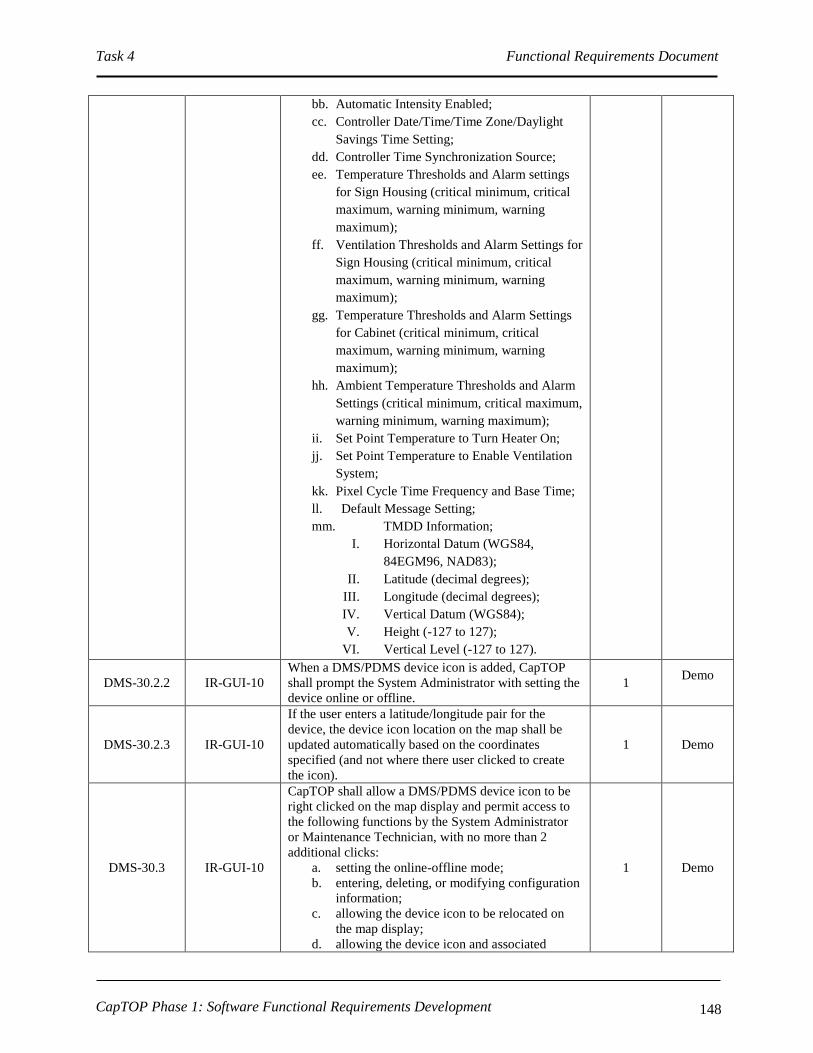
Task 4 Functional Requirements Document
CapTOP Phase 1: Software Functional Requirements Development 148
bb. Automatic Intensity Enabled;
cc. Controller Date/Time/Time Zone/Daylight
Savings Time Setting;
dd. Controller Time Synchronization Source;
ee. Temperature Thresholds and Alarm settings
for Sign Housing (critical minimum, critical
maximum, warning minimum, warning
maximum);
ff. Ventilation Thresholds and Alarm Settings for
Sign Housing (critical minimum, critical
maximum, warning minimum, warning
maximum);
gg. Temperature Thresholds and Alarm Settings
for Cabinet (critical minimum, critical
maximum, warning minimum, warning
maximum);
hh. Ambient Temperature Thresholds and Alarm
Settings (critical minimum, critical maximum,
warning minimum, warning maximum);
ii. Set Point Temperature to Turn Heater On;
jj. Set Point Temperature to Enable Ventilation
System;
kk. Pixel Cycle Time Frequency and Base Time;
ll. Default Message Setting;
mm. TMDD Information;
I. Horizontal Datum (WGS84,
84EGM96, NAD83);
II. Latitude (decimal degrees);
III. Longitude (decimal degrees);
IV. Vertical Datum (WGS84);
V. Height (-127 to 127);
VI. Vertical Level (-127 to 127).
DMS-30.2.2 IR-GUI-10
When a DMS/PDMS device icon is added, CapTOP
shall prompt the System Administrator with setting the
device online or offline.
1 Demo
DMS-30.2.3 IR-GUI-10
If the user enters a latitude/longitude pair for the
device, the device icon location on the map shall be
updated automatically based on the coordinates
specified (and not where there user clicked to create
the icon).
1 Demo
DMS-30.3 IR-GUI-10
CapTOP shall allow a DMS/PDMS device icon to be
right clicked on the map display and permit access to
the following functions by the System Administrator
or Maintenance Technician, with no more than 2
additional clicks:
a. setting the online-offline mode;
b. entering, deleting, or modifying configuration
information;
c. allowing the device icon to be relocated on
the map display;
d. allowing the device icon and associated
1 Demo
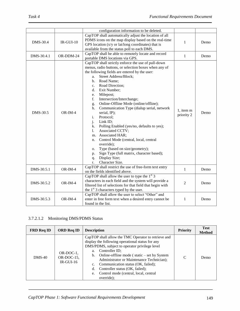
Task 4 Functional Requirements Document
CapTOP Phase 1: Software Functional Requirements Development 149
configuration information to be deleted.
DMS-30.4 IR-GUI-10
CapTOP shall automatically adjust the location of all
PDMS icons on the map display based on the real-time
GPS location (x/y or lat/long coordinates) that is
available from the status poll to each DMS.
1 Demo
DMS-30.4.1 OR-DDM-24 CapTOP shall be able to remotely locate and record
portable DMS locations via GPS. 1 Demo
DMS-30.5 OR-IM-4
CapTOP shall strictly enforce the use of pull-down
menus, radio buttons, or selection boxes when any of
the following fields are entered by the user:
a. Street Address/Block;
b. Road Name;
c. Road Direction;
d. Exit Number;
e. Milepost;
f. Intersection/Interchange;
g. Online-Offline Mode (online/offline);
h. Communication Type (dialup serial, network
serial, IP);
i. Protocol;
j. Link ID;
k. Polling Enabled (yes/no, defaults to yes);
l. Associated CCTV;
m. Associated HAR;
n. Control Mode (central, local, central
override);
o. Type (based on size/geometry);
p. Sign Type (full matrix, character based);
q. Display Size;
r. Character Size.
1, item m
priority 2 Demo
DMS-30.5.1 OR-IM-4 CapTOP shall restrict the use of free-form text entry
on the fields identified above. 1 Demo
DMS-30.5.2 OR-IM-4
CapTOP shall allow the user to type the 1st 3
characters in each field and the system will provide a
filtered list of selections for that field that begin with
the 1st 3 characters typed by the user.
2 Demo
DMS-30.5.3 OR-IM-4
CapTOP shall allow the user to select “Other” and
enter in free form text when a desired entry cannot be
found in the list.
1 Demo
3.7.2.1.2 Monitoring DMS/PDMS Status
FRD Req ID ORD Req ID Description Priority Test
Method
DMS-40
OR-DOC-1,
OR-DOC-15,
IR-GUI-16
CapTOP shall allow the TMC Operator to retrieve and
display the following operational status for any
DMS/PDMS, subject to operator privilege level
a. Controller ID;
b. Online-offline mode ( static – set by System
Administrator or Maintenance Technician);
c. Communication status (OK, failed);
d. Controller status (OK, failed);
e. Control mode (central, local, central
override);
C Demo

Task 4 Functional Requirements Document
CapTOP Phase 1: Software Functional Requirements Development 150
FRD Req ID ORD Req ID Description Priority Test
Method
f. Lock status (username if locked, if
implemented);
g. Current message;
h. Last contact (date/time);
i. Last communication status change
(date/time);
j. Alarm status.
DMS-40.1 OR-DOC-1,
OR-DOC-15
CapTOP subject to operator privilege level or related
3rd
party software shall allow the TMC Technician to
obtain the following operational status and operational
data for any DMS/PDMS,:
a. Online-offline mode ( static – set by System
Administrator or Maintenance Technician);
b. Communication status (OK, failed);
c. Control mode (central, local, central
override);
d. Lock status (username if locked, if
implemented);
e. Power errors;
f. Lamp errors;
g. Pixel errors;
h. Light sensor errors;
i. Last error;
j. Climate control errors;
k. Current message;
l. Photocell level;
m. Intensity/Brightness level;
n. Automatic intensity enabled;
o. Sign housing temperature;
p. Sign housing humidity;
q. Sign controller cabinet temperature;
r. Sign controller cabinet humidity;
s. Controller date/time/time zone/daylight
savings time setting;
t. Controller time synchronization source;
u. Heater thresholds and alarms for cabinet
housing and cabinet;
v. Ventilation thresholds and alarms;
w. Pixel cycle time frequency;
x. Default message setting;
y. Last contact (date/time);
z. Last communication status change
(date/time);
aa. Alarm status.
1 Demo
DMS-40.1.1 OR-DOC-1
OR-DOC-15
CapTOP shall be able to report for current message
both the message commanded to be displayed by the
DMS controller and a pixel-by-pixel mapping of the
illuminated pixels in real time based on measurement
made by the sign electronics.
C Demo
DMS-40.2 OR-DOC-1,
OR-DOC-15
CapTOP subject to operator privilege level or related
3rd
party software shall allow the TMC Technician to
obtain the list of fonts loaded in the DMS/PDMS.
1 Demo
DMS-40.3 OR-DOC-1 CapTOP subject to operator privilege level or related
3rd
party software shall provide the same status 1 Demo
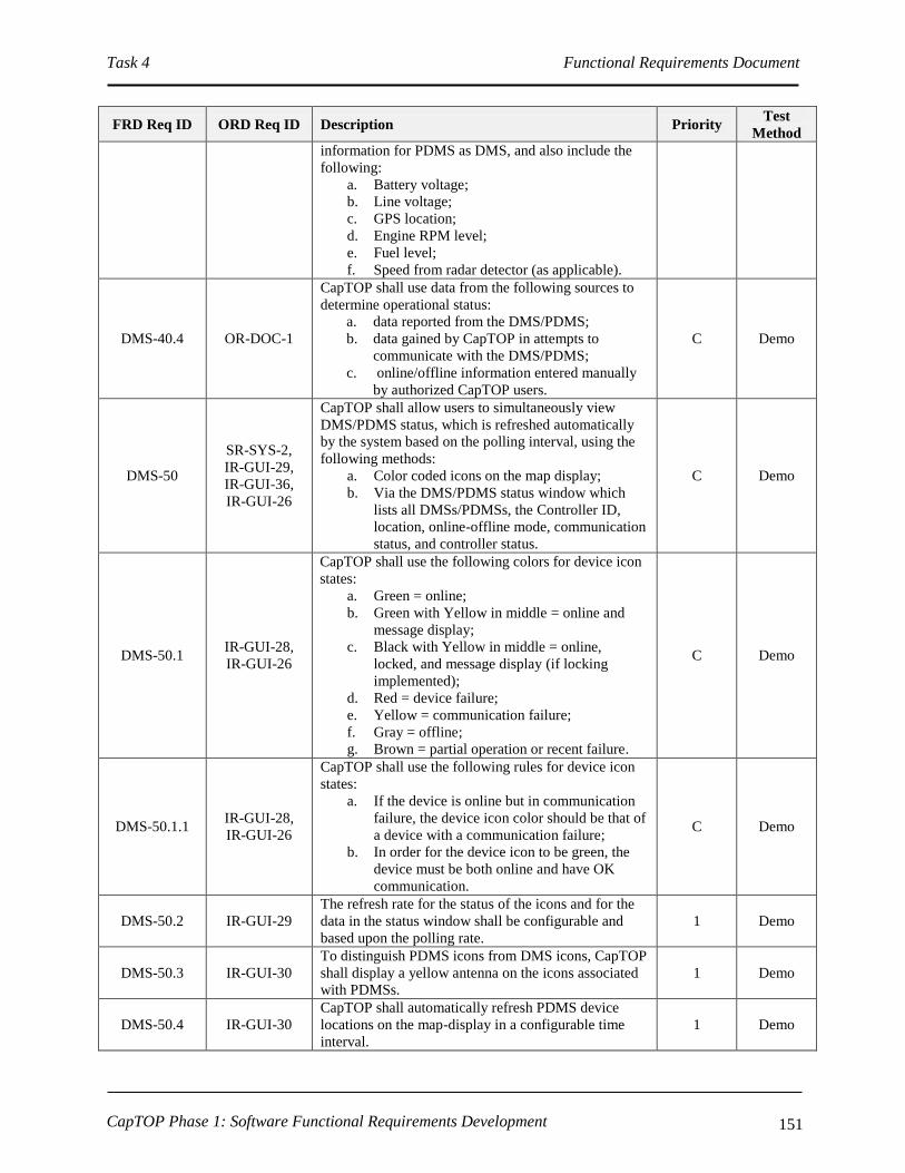
Task 4 Functional Requirements Document
CapTOP Phase 1: Software Functional Requirements Development 151
FRD Req ID ORD Req ID Description Priority Test
Method
information for PDMS as DMS, and also include the
following:
a. Battery voltage;
b. Line voltage;
c. GPS location;
d. Engine RPM level;
e. Fuel level;
f. Speed from radar detector (as applicable).
DMS-40.4 OR-DOC-1
CapTOP shall use data from the following sources to
determine operational status:
a. data reported from the DMS/PDMS;
b. data gained by CapTOP in attempts to
communicate with the DMS/PDMS;
c. online/offline information entered manually
by authorized CapTOP users.
C Demo
DMS-50
SR-SYS-2,
IR-GUI-29,
IR-GUI-36,
IR-GUI-26
CapTOP shall allow users to simultaneously view
DMS/PDMS status, which is refreshed automatically
by the system based on the polling interval, using the
following methods:
a. Color coded icons on the map display;
b. Via the DMS/PDMS status window which
lists all DMSs/PDMSs, the Controller ID,
location, online-offline mode, communication
status, and controller status.
C Demo
DMS-50.1 IR-GUI-28,
IR-GUI-26
CapTOP shall use the following colors for device icon
states:
a. Green = online;
b. Green with Yellow in middle = online and
message display;
c. Black with Yellow in middle = online,
locked, and message display (if locking
implemented);
d. Red = device failure;
e. Yellow = communication failure;
f. Gray = offline;
g. Brown = partial operation or recent failure.
C Demo
DMS-50.1.1 IR-GUI-28,
IR-GUI-26
CapTOP shall use the following rules for device icon
states:
a. If the device is online but in communication
failure, the device icon color should be that of
a device with a communication failure;
b. In order for the device icon to be green, the
device must be both online and have OK
communication.
C Demo
DMS-50.2 IR-GUI-29
The refresh rate for the status of the icons and for the
data in the status window shall be configurable and
based upon the polling rate.
1 Demo
DMS-50.3 IR-GUI-30
To distinguish PDMS icons from DMS icons, CapTOP
shall display a yellow antenna on the icons associated
with PDMSs.
1 Demo
DMS-50.4 IR-GUI-30
CapTOP shall automatically refresh PDMS device
locations on the map-display in a configurable time
interval.
1 Demo

Task 4 Functional Requirements Document
CapTOP Phase 1: Software Functional Requirements Development 152
FRD Req ID ORD Req ID Description Priority Test
Method
DMS-50.5 IR-GUI-31
CapTOP shall allow the user to obtain summary status
information (refer to DMS-40 for the list of fields) by
hovering over a DMS/PDMS icon.
1 Demo
DMS-50.6 IR-GUI-29
CapTOP shall allow the user to select on any
DMS/PDMS in the DMS/PDMS status window (refer
to DMS-50 item b) and view all details (full status,
configuration information, and DMS/PDMS controls)
pertaining to that DMS/PDMS.
1 Demo
DMS-60
SR-SYS-2,
IR-GUI-29,
IR-GUI-31,
IR-GUI-32
CapTOP shall provide a menu option to search for a
DMS by the following methods:
a. by device ID;
b. by IP address/drop address/channel ID/phone
number;
c. by street name;
d. by geographical address;
e. by intersection/interchange.
1 Demo
DMS-60.1 SR-SYS-2,
IR-GUI-29
CapTOP shall allow the TMC Operator to search for
DMSs/PDMSs using a rubber-band style box on the
map display to search an area.
1 Demo
DMS-60.2 SR-SYS-2,
IR-GUI-29
The result of each search shall be a list of
DMSs/PDMSs that are sorted, by default, by device
ID.
1 Demo
DMS-60.3 SR-SYS-2,
IR-GUI-29
The result of each search shall be a list of
DMSs/PDMSs sortable by device ID, IP address/drop
address/channel ID/phone number, street name,
geographical address, and intersection/interchange.
1 Demo
DMS-70 IR-GUI-13
CapTOP shall provide a monitoring and control
interface through communication servers for managing
all DMS/PDMS.
C Demo
DMS-70.1
OR-DOC-11,
SR-SYS-8,
SR-SYS-23
CapTOP shall provide a monitor and control interface
to all DMSs/PDMSs using the latest DMS/PDMS
NTCIP 1203 standard, if supported by the
DMS/PDMS; otherwise, CapTOP shall conform to the
existing DMS/PDMS’s supported protocol.
C Demo
DMS-70.1.1
OR-DOC-11,
SR-SYS-8,
SR-SYS-23
CapTOP shall communicate using NTCIP to the
following DMSs/PDMSs:
a. MARK IV FP9000;
b. VER-MAC 3048SCEN2008;
c. VER-MAC 3056SCEN2007.
C Demo
DMS-70.1.2
OR-DOC-11,
SR-SYS-8,
SR-SYS-23
For DMS/PDMS that do not support the NTCIP
protocol, CapTOP shall implement data
communications using native protocols for the
following controllers:
a. PSC SMC2000HE;
b. PSC SME200FM;
c. FDS Controllers;
d. Addco Controllers.
C Demo
DMS-70.2 IR-GUI-13
CapTOP shall be able to request DMS/PDMS status
and obtain status response data through the monitoring
and control interface including all data items noted in
DMS-40.1 and DMS-40.3.
C Demo
DMS-70.2.1 OR-DOC-2,
OR-DOC-3,
CapTOP shall support a polling interval range from 0
to 99999 seconds, where zero indicates no polling. 1 Demo
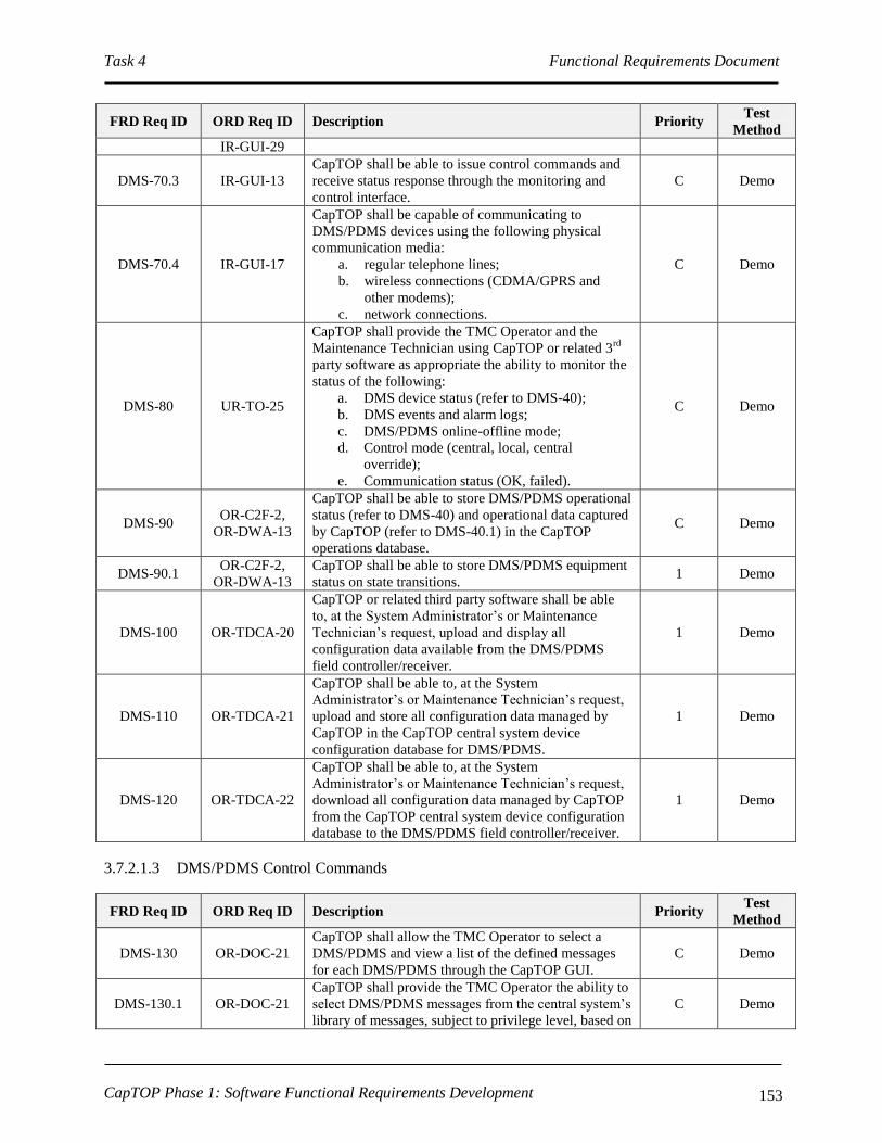
Task 4 Functional Requirements Document
CapTOP Phase 1: Software Functional Requirements Development 153
FRD Req ID ORD Req ID Description Priority Test
Method
IR-GUI-29
DMS-70.3 IR-GUI-13
CapTOP shall be able to issue control commands and
receive status response through the monitoring and
control interface.
C Demo
DMS-70.4 IR-GUI-17
CapTOP shall be capable of communicating to
DMS/PDMS devices using the following physical
communication media:
a. regular telephone lines;
b. wireless connections (CDMA/GPRS and
other modems);
c. network connections.
C Demo
DMS-80 UR-TO-25
CapTOP shall provide the TMC Operator and the
Maintenance Technician using CapTOP or related 3rd
party software as appropriate the ability to monitor the
status of the following:
a. DMS device status (refer to DMS-40);
b. DMS events and alarm logs;
c. DMS/PDMS online-offline mode;
d. Control mode (central, local, central
override);
e. Communication status (OK, failed).
C Demo
DMS-90 OR-C2F-2,
OR-DWA-13
CapTOP shall be able to store DMS/PDMS operational
status (refer to DMS-40) and operational data captured
by CapTOP (refer to DMS-40.1) in the CapTOP
operations database.
C Demo
DMS-90.1 OR-C2F-2,
OR-DWA-13
CapTOP shall be able to store DMS/PDMS equipment
status on state transitions. 1 Demo
DMS-100 OR-TDCA-20
CapTOP or related third party software shall be able
to, at the System Administrator’s or Maintenance
Technician’s request, upload and display all
configuration data available from the DMS/PDMS
field controller/receiver.
1 Demo
DMS-110 OR-TDCA-21
CapTOP shall be able to, at the System
Administrator’s or Maintenance Technician’s request,
upload and store all configuration data managed by
CapTOP in the CapTOP central system device
configuration database for DMS/PDMS.
1 Demo
DMS-120 OR-TDCA-22
CapTOP shall be able to, at the System
Administrator’s or Maintenance Technician’s request,
download all configuration data managed by CapTOP
from the CapTOP central system device configuration
database to the DMS/PDMS field controller/receiver.
1 Demo
3.7.2.1.3 DMS/PDMS Control Commands
FRD Req ID ORD Req ID Description Priority Test
Method
DMS-130 OR-DOC-21
CapTOP shall allow the TMC Operator to select a
DMS/PDMS and view a list of the defined messages
for each DMS/PDMS through the CapTOP GUI.
C Demo
DMS-130.1 OR-DOC-21
CapTOP shall provide the TMC Operator the ability to
select DMS/PDMS messages from the central system’s
library of messages, subject to privilege level, based on
C Demo

Task 4 Functional Requirements Document
CapTOP Phase 1: Software Functional Requirements Development 154
FRD Req ID ORD Req ID Description Priority Test
Method
the following:
a. type of DMS/PDMS;
b. location of DMS/PDMS;
c. type of incident;
d. type of special event;
e. severity of incident;
f. size of special event.
DMS-130.2 OR-DOC-21 CapTOP shall provide the TMC Operator the ability to
enter a free-form message to send to a DMS/PDMS. C Demo
DMS-140 OR-DOC-21 CapTOP shall require supervisor approval of all free-
form messages prior to transmission by the Operator. C Demo
DMS-150
OR-DOC-17,
SR-SYS-23,
OR-TID-4
CapTOP shall allow the TMC Operator to issue the
following commands to any DMS/PDMS, using an
intuitive GUI control window, subject to operator
privilege level:
a. display message;
b. blank message;
c. display date/time;
d. display travel time message (destination,
distance, travel time range);
e. edit DMS/PDMS message schedule;
f. display diagnostic message.
C Demo
DMS-160 OR-DOC-17,
SR-SYS-23
CapTOP subject to operator privilege level or related
3rd
party software shall allow the System Administrator
or Maintenance Technician to issue the following
commands to any DMS/PDMS, using an intuitive GUI
control window:
a. display message;
b. blank message;
c. display date/time;
d. set controller date/time/time zone/time
synchronization source;
e. display pixel test;
f. display pixel pattern;
g. test RAM;
h. test sign driver;
i. cut network power;
j. restore network power;
k. display all status and configuration
information (refer to DMS-40.1*);
l. modify configuration information (refer to
DMS-30.2*);
m. edit and delete messages;
n. delete volatile messages;
o. edit DMS/PDMS message schedule;
p. set control mode (central, local, central
override);
q. set online-offline mode;
r. reset controller.
C Demo
DMS-160.1 OR-DOC-17,
SR-SYS-23
CapTOP shall allow the TMC Operator to specify a
value for an optional parameter called “maximum
message duration”, represented in seconds from 0-
9,999,999.
1 Demo

Task 4 Functional Requirements Document
CapTOP Phase 1: Software Functional Requirements Development 155
FRD Req ID ORD Req ID Description Priority Test
Method
DMS-170 OR-DOC-22
CapTOP shall allow the TMC Operator to transmit a
message to a DMS and PDMS manually and according
to a schedule, subject to operator privilege level.
C Demo
DMS-180 SR-SYS-2
CapTOP shall allow two or more different users to
simultaneously control two or more different
DMSs/PDMSs at the same time.
C Demo
DMS-190 SR-SYS-2, IR-
GUI-19
CapTOP shall allow users, with proper privileges, to
monitor and control any DMS/PDMS, from any
CapTOP workstation.
C Demo
DMS-200 SR-SYS-2,
OR-SMM-5
CapTOP shall provide a software locking mechanism
to prevent 2 or more operators from simultaneously
controlling the same DMS/PDMS.
3 Demo
DMS-200.1 SR-SYS-2,
OR-SMM-5
If the DMS/PDMS is locked, CapTOP shall allow all
TMC operators, subject to privilege level, to only view
the status and current message of a DMS/PDMS (not
control).
3 Demo
DMS-200.2 SR-SYS-2,
OR-SMM-5
CapTOP shall provide a notification to the user when
he attempts to control a DMS/PDMS currently locked
by another user.
3 Demo
DMS-200.2.1 SR-SYS-2,
OR-SMM-5
The notification shall provide the ID of the
DMS/PDMS and the user name that has the
DMS/PDMS locked.
3 Demo
DMS-200.3 OR-SMM-5
CapTOP shall allow a DMS icon to be left clicked on
the map display by the TMC Operator, subject to
privilege level, and enable locking with no more than 2
clicks.
3 Demo
DMS-200.4 OR-SMM-5 CapTOP shall remove DMS locks set by an individual
user when that user logs out of the system 3 Demo
DMS-200.5 OR-SMM-5 CapTOP shall remove DMS locks after a configurable
time period has elapsed. 3 Demo
DMS-210 SR-SYS-2,
OR-SMM-5
CapTOP shall provide the ability for a user with
override privileges to unlock DMSs/PDMSs that are
locked.
3 Demo
DMS-210.1 OR-SMM-5 CapTOP shall issue an alert to a user when a DMS that
the user locked has been overridden. 3 Demo
3.7.2.1.4 DMS/PDMS Message Scheduler
FRD Req ID ORD Req ID Description Priority Test
Method
DMS-220 OR-DOC-22,
OR-DOC-30
CapTOP shall be able to define and schedule
DMS/PDMS messages to be displayed automatically
using a schedule editor.
C Demo
DMS-220.1 OR-DOC-22,
OR-DOC-30
The CapTOP schedule capability shall permit time of
day recurring and non-recurring entries for
DMS/PDMS messages.
C Demo
DMS-220.2 OR-DOC-22,
OR-DOC-30
The schedule shall permit a non-recurring, one-time
only message to be transmitted to a DMS/PDMS,
where the user specifies a schedule name, DMS/PDMS
ID, message ID, reminder date/time, start date/time
and end date/time.
C Demo
DMS-220.3 OR-DOC-22,
OR-DOC-30
The schedule shall permit a non-recurring, one-time
only message to be transmitted to a DMS/PDMS 1 Demo

Task 4 Functional Requirements Document
CapTOP Phase 1: Software Functional Requirements Development 156
FRD Req ID ORD Req ID Description Priority Test
Method
group, where the user specifies a schedule name, group
ID, message ID, reminder date/time, start date/time
and end date/time.
DMS-220.4 OR-DOC-22,
OR-DOC-30
CapTOP shall provide a recurring schedule capability
and permit any of the following recurring entry types:
a. Weekdays – Monday through Friday;
b. Weekends – Saturday and Sunday only;
c. All Days – Monday through Sunday;
d. One day or any combination of days per
week;
e. One day or any combination of days per
month.
C Demo
DMS-220.4.1 OR-DOC-22,
OR-DOC-30
CapTOP shall allow recurring schedule entries to be
created for a DMS/PDMS, where the user specifies a
schedule name, DMS/PDMS ID, recurring entry type,
message ID, reminder date/time, start date/time and
end date/time (optional).
C Demo
DMS-220.4.2 OR-DOC-22,
OR-DOC-30
CapTOP shall allow recurring schedule entries to be
created for a DMS/PDMS group, where the user
specifies a schedule name, group ID, recurring entry
type, message ID, start date/time and end date/time
(optional).
1 Demo
DMS-220.4.3 OR-DOC-22,
OR-DOC-30
CapTOP shall permit an optional end date to be
specified for all recurring schedule entries. 1 Demo
DMS-
220.4.3.1
OR-DOC-22,
OR-DOC-30
CapTOP shall implement the recurring scheduling
indefinitely if no end date is specified. 1 Demo
DMS-220.4.4 OR-DOC-22,
OR-DOC-30
CapTOP shall allow a Holiday schedule to be specified
for the CapTOP system. 1 Demo
DMS-
220.4.4.1
OR-DOC-22,
OR-DOC-30
CapTOP shall allow the user to indicate whether each
Holiday is treated as an exception to the recurring
schedule.
1 Demo
DMS-
220.4.4.2
OR-DOC-22,
OR-DOC-30
CapTOP shall allow the user to specify each Holiday
exception to be treated as either a Weekend or
Weekday whenever encountered.
1 Demo
DMS-230 OR-DOC-22,
OR-DOC-30
CapTOP shall allow the TMC Operator to edit and
delete scheduled entries for DMSs/PDMSs. 1 Demo
3.7.2.1.5 DMS/PDMS Reports
FRD Req ID ORD Req ID Description Priority Test
Method
DMS-240 OR-DOC-22,
OR-DOC-30
CapTOP shall allow the TMC Operator to produce a
report of all scheduled entries for an individual
DMS/PDMS or all DMSs/PDMSs.
2
DMS-240.1 OR-DOC-22,
OR-DOC-30
The report shall list all schedule entries, and shall
contain the following:
a. Schedule name;
b. DMS/PDMS or Group ID;
c. Message ID;
d. Recurrent entry type (optional);
e. State Date/Time;
f. End Date/Time (optional).
2
DMS-250 SR-SYS-22, CapTOP shall be able to automatically generate real- 2 Demo

Task 4 Functional Requirements Document
CapTOP Phase 1: Software Functional Requirements Development 157
FRD Req ID ORD Req ID Description Priority Test
Method
SR-SYS-36,
OR-DOC-4,
IR-GUI-8
time tabular reports that show the real-time operational
status and operational data of all DMSs/PDMSs.
DMS-250.1
SR-SYS-22,
SR-SYS-36,
OR-DOC-4,
IR-GUI-8
CapTOP shall provide the following information in the
DMS/PDMS status report:
a. DMS/PDMS ID;
b. Location;
c. Online-offline mode;
d. Locked or unlocked status with user name (if
implemented);
e. Communication status (OK, failed);
f. Control mode (central, local, central
override);
g. Alarm status;
h. Message ID being displayed.
2 Demo
DMS-260 OR-DWA-7
CapTOP shall be able to produce the following
performance reports for evaluating the performance of
DMSs/PDMSs, using data in the CapTOP operations
and archived databases:
a. Number of times a DMS/PDMS transitioned
from online to offline over a specified time
period;
b. Number of times a DMS/PDMS transitioned
from no device failure to device failure over a
specified time period;
c. Number of times a DMS/PDMS transitioned
from no communication failure to
communication failure over a specified time
period.
2 Demo
DMS-270
SR-SYS-22,
SR-SYS-36,
OR-DOC-4,
IR-GUI-8,
UR-TO-11,
OR-TID-3
CapTOP shall be able to display and print the
following reports:
a. For a user entered DMS ID, provide a
message history report, consisting of the DMS
ID, message ID, date/time transmitted, and
username who transmitted the message.
b. For a user entered user ID, provide a message
history report, consisting of the User ID,
DMS ID, message ID, and date/time
transmitted.
c. For a user entered CCTV ID, provide a full
device configuration report;
d. For a user specified time-interval, provide a
DMS message history report, consisting of the
DMS ID, message ID, date/time transmitted,
and username who transmitted the message;
e. An ad-hoc report where the user can query
any data stored in DMS related databases.
2 Demo
DMS-270.1
SR-SYS-22,
SR-SYS-36,
OR-DOC-4,
IR-GUI-8
CapTOP shall support the following capabilities for all
reports:
a. be able to display all reports in a tabular
format;
b. be able to display graphical reports in a
Microsoft Excel-like 2-dimensional or 3-
dimensional format.
a. 2
b. 2
c. 2
Demo

Task 4 Functional Requirements Document
CapTOP Phase 1: Software Functional Requirements Development 158
FRD Req ID ORD Req ID Description Priority Test
Method
c. be able to print all reports in landscape or
portrait modes;
d. include the report name and date generated on
the header;
e. support a template capability for each report,
allowing the user to select which fields to
display;
f. include the page number on the footer.
d. 2
e. 2
f. 2
3.7.2.1.6 DMS/PDMS Message Editor
FRD Req ID ORD Req ID Description Priority Test
Method
DMS-280
OR-DOC-18,
OR-DOC-19,
OR-DOC-20,
OR-DOC-32
The CapTOP software shall provide a DMS message
editor that supports the following:
a. allows the TMC Operator to create a single-
phase message;
b. allows the TMC Operator to create a multiple-
phase message and specify the time between
phases in 1/10th
second increments from 1.0 -
25.5, with a default of 2.0 seconds;
c. allows the TMC Operator to select a message
from the central system’s library;
d. allows the TMC Operator to edit a typed
message;
e. allows the TMC Operator to edit any field of
a message from the library;
f. allows the TMC Operator to save the new
message in the library or replace an existing
message in the library;
I. requires Supervisor approval to save
the message.
II. requires the TMC Operator to
provide a unique message ID for the
saved message;
g. requires the TMC Operator to assign a
message priority to each message;
h. provides the ability to identify and store the
type of signs that support the message;
i. allows the TMC Operator to view a
simulation of the message to scale on a pixel-
by-pixel basis with regard to how the message
will actually appear on each sign type based
on the sign dimensions and mode (full-matrix
or character based).
C Demo
DMS-290
OR-DOC-18,
OR-DOC-19,
OR-DOC-20,
OR-TID-4
CapTOP shall support the following message features
in the message editor:
a. message formats using the Mark-Up
Language for Transportation Information
(MULTI) DMS mark-up language as
specified in the NTCIP document 1203
version 2;
All
priority 1
except
item g is
priority 3
Demo

Task 4 Functional Requirements Document
CapTOP Phase 1: Software Functional Requirements Development 159
FRD Req ID ORD Req ID Description Priority Test
Method
b. left, right, or centered justification on a per
line basis;
c. creation of messages in full-matrix or
character-based mode;
d. support for different font-types per message
(multiple types per message);
e. support for different font-sizes per message
(multiple sizes per message);
f. the ability to specify the number of pixels
between lines (line spacing);
g. the ability to specify the number of pixels
between characters (character spacing);
h. selection of graphics in .bmp format for full-
matrix signs;
i. selection of colors for full-matrix signs;
j. the ability to flash words in the message;
k. the ability to flash lines in the message;
l. the ability to flash the entire message;
m. the ability to specify a flash rate as a number
0.0 to 25.5 in .1 second increments;
n. the ability to bold words in the message;
o. the ability to reverse the pixels for a word;
p. the ability to reverse the pixels for a line;
q. the ability to reverse the pixels for a message;
r. the ability to insert the current time into any
message using any of the following of
formats: hh:mm AM/PM or hh:mm or
hh:mm:ss AM/PM or hh:mm:ss;
s. the ability to insert the current date into any
message using any of the following formats:
mm/dd/yy or mmm dd, yyyy;
t. the ability to insert the current outside
ambient temperature into any message (if
applicable).
u. the ability to insert special characters into the
message (as defined by the manufacturer);
v. the ability to insert the current speed, as
measured by radar detectors (if built into the
DMS/PDMS), into the message;
w. the ability to insert a one-destination, one-
line, two-line or three-line travel time
message consisting of destination, distance
and travel time range;
x. the ability to insert a two-line, two-destination
travel time message with each line consisting
of destination, distance and travel time range;
y. the ability to insert a three-line, three-
destination travel time message with each line
consisting of destination, distance and travel
time range;
z. notification to the TMC Operator if the
message is too big to be displayed;
DMS-300 OR-DOC-18,
OR-DOC-19,
CapTOP shall spell check all created messages and
messages stored in the central system’s library, and 1 Demo

Task 4 Functional Requirements Document
CapTOP Phase 1: Software Functional Requirements Development 160
FRD Req ID ORD Req ID Description Priority Test
Method
OR-DOC-20 prohibit the use of misspelled and restricted words in
any message.
DMS-300.1
OR-DOC-18,
OR-DOC-19,
OR-DOC-20
CapTOP shall provide a configurable list of prohibited
restricted words editable only by the System
Administrator.
1 Demo
DMS-300.2
OR-DOC-18,
OR-DOC-19,
OR-DOC-20
CapTOP shall use a dictionary to ensure all words are
spelled correctly. 1 Demo
DMS-300.3
OR-DOC-18,
OR-DOC-19,
OR-DOC-20
CapTOP shall allow the System Administrator to add,
change and remove words from the dictionary. 1 Demo
DMS-300.4
OR-DOC-18,
OR-DOC-19,
OR-DOC-20
CapTOP shall provide an error message listing any
words that do not pass the spell check or restricted
word check.
1 Demo
DMS-300.4.1
OR-DOC-18,
OR-DOC-19,
OR-DOC-20
CapTOP shall prevent the message from being
transmitted and saved until the errors are corrected or
the message is approved by the TMC Manager.
1 Demo
DMS-310 OR-DOC-21
The CapTOP DMS message library in the central
system shall have the following capabilities:
a. be capable of storing a minimum of 5,000
messages;
b. be capable of having a name associated with
the library;
c. support multiple libraries;
d. be capable of creating, deleting and editing
libraries and messages within the library, in
accordance with user privileges;
e. be capable of storing messages that are sign-
specific using a message attribute to denote
the message type;
f. be capable of searching for messages in the
library using a keyword or phrase;
g. be capable of storing messages applicable to
multiple sign types that can fit the message
using a message attribute to denote the
message type;
h. be capable of storing the messages in text
format;
i. allow the TMC Operator to delete messages,
one at a time, in accordance with user
privileges;
j. allow the TMC Operator to delete all
messages in one command in accordance with
user privileges;
k. allow the TMC Operator to select multiple
messages and delete them in one command, in
accordance with user privileges.
C Demo
DMS-320 OR-DOC-21
CapTOP shall allow the same message to be sent to
multiple DMSs of the same type using a drag and drop
capability, in accordance with user privileges.
1 Demo
DMS-330 OR-DOC-21
CapTOP shall allow the same message to be sent to
multiple DMSs of the same type using a multiple
selection capability, in accordance with user privileges.
1 Demo

Task 4 Functional Requirements Document
CapTOP Phase 1: Software Functional Requirements Development 161
FRD Req ID ORD Req ID Description Priority Test
Method
DMS-340 OR-DOC-21
CapTOP shall allow the same message to be sent to all
DMSs in the same group, in accordance with user
privileges.
1 Demo
DMS-350 OR-DOC-21
CapTOP shall allow, in accordance with user
privileges, the same message to be sent to multiple
DMSs of different sizes, provided the message is able
to fit on the sign.
1 Demo
DMS-350.1 OR-DOC-21
CapTOP shall abbreviate words automatically for
messages that don’t fit on a particular sign, to
determine if the message will fit for a particular type.
1 Demo
DMS-350.2 OR-DOC-21 CapTOP shall use a configurable list of abbreviations,
editable only by the System Administrator. 1 Demo
DMS-350.3 OR-DOC-21
CapTOP shall notify the user in the event a message is
attempted to be transmitted to a sign that is too small
to display the message.
1 Demo
DMS-350.4 OR-DOC-21 CapTOP shall prevent truncated messages from being
transmitted to signs. 1 Demo
DMS-350.5 OR-DOC-21
After a message has been truncated or abbreviations
inserted into a message, CapTOP will prompt a TMC
Operator currently active on the system for
acceptability of the revised message prior to display,
only displaying the message if the TMC Operator
accepts the revision.
1 Demo
DMS-360 OR-DOC-31 CapTOP shall notify the TMC Operator of any failed
message transmissions. 1 Demo
DMS-370
OR-DOC-31,
SR-SYS-24,
IR-GUI-29
CapTOP shall take no longer than 60 seconds after
initiation of message transmission to update the
message on the sign and receive confirmation the
message was posted via the communication protocol.
1 Demo
DMS-380 OR-DOC-21
CapTOP shall take no longer than 40 seconds after
receipt of confirmation of message posting or failure to
update the status of the DMS within the system.
1 Demo
DMS-390 OR-DOC-21 CapTOP shall provide a parameter that specifies the
maximum number of phases per DMS. 1 Demo
DMS-400 OR-DOC-21 CapTOP shall be able to manage a DMS inventory of
5,000 signs. 1 Demo
DMS-410 OR-DOC-21,
SR-SYS-2
CapTOP shall manage messages coming from multiple
operators and the system scheduler, and shall prioritize
all of these into a single list and shall post the message
with the highest priority.
1 Demo
DMS-410.1 OR-DOC-21,
SR-SYS-2
CapTOP shall have the ability to notify the TMC
Operator, TMC Manager, and Maintenance Manager
when there is a conflict with two or more messages, of
the same priority, attempting to be sent out at the same
time or within 5 minutes of one another.
1 Demo
DMS-410.2 OR-DOC-21,
SR-SYS-2
CapTOP shall display an error message whenever a
lower priority message is attempted to be transmitted
while a higher priority message is displayed.
1 Demo
DMS-420 OR-DOC-21
CapTOP shall allow the TMC Operator, subject to
privilege level, to be able to create, delete, and edit
DMS groups.
1 Demo
DMS-420.1 OR-DOC-21 CapTOP shall provide the following fields in the
definition of each group: 1 Demo

Task 4 Functional Requirements Document
CapTOP Phase 1: Software Functional Requirements Development 162
FRD Req ID ORD Req ID Description Priority Test
Method
a. Group name;
b. List of DMSs having membership in the
group.
DMS-420.2 OR-DOC-21 CapTOP shall allow each DMS to have membership in
1 or more DMS groups. 1 Demo
DMS-420.3 OR-DOC-21 CapTOP shall ensure that each DMS in the group is of
the same type and of the same size. 1 Demo
3.7.2.1.7 Font Editor
FRD Req ID ORD Req ID Description Priority Test
Method
DMS-430 OR-DOC-19 CapTOP shall provide a DMS/PDMS font editor that
provides the ability to create, modify, and delete fonts. 1 Demo
DMS-430.1 OR-DOC-19
The TMC Operator, with appropriate privilege, shall
be able to define a font with the following
characteristics:
a. Font name;
b. Font height;
c. Space between characters;
d. Space between lines;
e. List of characters, and for each provide:
I. ASCII code;
II. Character symbol letter;
III. Character symbol represented as
bitmap matrix;
IV. Width.
1 Demo
DMS-430.2 OR-DOC-19
The font editor shall provide a bitmap-type editor,
based on the height and width of the character set, that
allows pixels to be turned on/off to create each
character.
1 Demo
DMS-430.3 OR-DOC-19
The font editor shall provide the ability to clear the
editing screen, reverse pixel settings for the character,
and zoom in and out on the display.
1 Demo
DMS-430.4 OR-DOC-19
The font editor shall provide a display that lists all the
characters in the font and provide a display that
represents how each character will appear on the
DMS/PDMS.
1 Demo
DMS-430.5 OR-DOC-19 The font editor shall provide a display that lists all the
available fonts. 1 Demo
DMS-430.6 OR-DOC-19
The font editor shall provide a report that allows the
TMC Operator to print all the characters in the font,
with their ASCII code, and width displayed.
2 Demo
DMS-430.6.1 OR-DOC-19
The report shall also indicate the font name, font
height, space between characters, and space between
lines.
2 Demo
3.7.2.1.8 Graphics Editor
FRD Req ID ORD Req ID Description Priority Test
Method
DMS-440 OR-DOC-19 CapTOP shall provide a DMS/PDMS graphics editor
that provides the ability to create, modify, and delete 1 Demo

Task 4 Functional Requirements Document
CapTOP Phase 1: Software Functional Requirements Development 163
FRD Req ID ORD Req ID Description Priority Test
Method
graphics.
DMS-440.1 OR-DOC-19
The TMC Operator, with appropriate privilege, shall
be able to define a graphic with the following
characteristics:
a. graphic name;
b. graphic height;
c. graphic width;
d. graphic represented as a bitmap matrix.
1 Demo
DMS-440.2 OR-DOC-19
The graphics editor shall provide a bitmap-type editor,
sized for the height and width of the graphic, that
allows pixels to be turned on/off to create each
graphic.
1 Demo
DMS-440.3 OR-DOC-19 The graphics editor shall provide the ability to import
bitmaps into the editor. 1 Demo
DMS-440.4 OR-DOC-19
The graphics editor shall provide the ability to clear
the editing screen, reverse pixel settings for the image,
and zoom in and out on the display.
1 Demo
DMS-440.5 OR-DOC-19 The graphics editor shall provide a display that lists all
the graphics that are available in the system. 1 Demo
DMS-440.5.1 OR-DOC-19 The graphics editor shall provide a simulation display
of the graphic as it will appear on the DMS/PDMS. 1 Demo
DMS-440.6 OR-DOC-19 The graphics editor shall provide a report that allows
the TMC Operator to print each graphic. 1 Demo
DMS-440.6.1 OR-DOC-19 The report shall also indicate the graphic name,
graphic height, and graphic. 1 Demo
3.7.2.1.9 DMS/PDMS Logging Requirements
FRD Req ID ORD Req ID Description Priority Test
Method
DMS-450 UR-TO-11,
OR-TOM-1
CapTOP shall store and time stamp all operator and
system activities that pertain to DMSs/PDMSs and
provide the output in a time sequential log.
C Demo
DMS-450.1
UR-TO-11,
OR-C2F-3,
OR-C2F-4,
OR-DWA-13
CapTOP shall have the capability to automatically log
the following user activities to the log database that
pertain to DMSs/PDMSs:
a. any operator-initiated action resulting in a
request to access information;
b. any operator-initiated action that attempts to,
or results in, a change to a DMS/PDMS;
c. changes to the message library (new
messages, changes to existing messages;
deleted messages);
d. message transmission to a DMS/PDMS;
e. when the user changes the DMS/PDMS
configuration data;
f. results from operator-initiated sign diagnostic
and sign status requests
g. operator login;
h. operator logout.
(Note: also refer to the LOG-* requirements).
C Demo
DMS-450.2 UR-TO-11 CapTOP shall have the capability to automatically log
the following system activities to the log database that C Demo
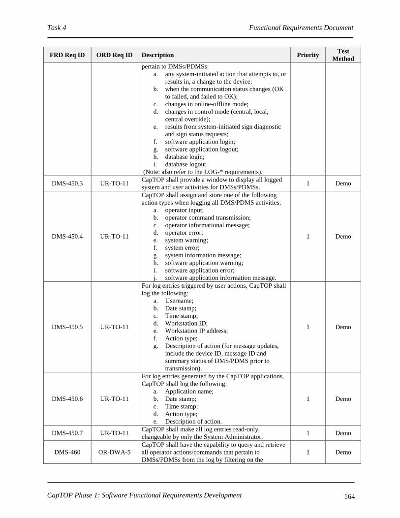
Task 4 Functional Requirements Document
CapTOP Phase 1: Software Functional Requirements Development 164
FRD Req ID ORD Req ID Description Priority Test
Method
pertain to DMSs/PDMSs:
a. any system-initiated action that attempts to, or
results in, a change to the device;
b. when the communication status changes (OK
to failed, and failed to OK);
c. changes in online-offline mode;
d. changes in control mode (central, local,
central override);
e. results from system-initiated sign diagnostic
and sign status requests;
f. software application login;
g. software application logout;
h. database login;
i. database logout.
(Note: also refer to the LOG-* requirements).
DMS-450.3 UR-TO-11 CapTOP shall provide a window to display all logged
system and user activities for DMSs/PDMSs. 1 Demo
DMS-450.4 UR-TO-11
CapTOP shall assign and store one of the following
action types when logging all DMS/PDMS activities:
a. operator input;
b. operator command transmission;
c. operator informational message;
d. operator error;
e. system warning;
f. system error;
g. system information message;
h. software application warning;
i. software application error;
j. software application information message.
1 Demo
DMS-450.5 UR-TO-11
For log entries triggered by user actions, CapTOP shall
log the following:
a. Username;
b. Date stamp;
c. Time stamp;
d. Workstation ID;
e. Workstation IP address;
f. Action type;
g. Description of action (for message updates,
include the device ID, message ID and
summary status of DMS/PDMS prior to
transmission).
1 Demo
DMS-450.6 UR-TO-11
For log entries generated by the CapTOP applications,
CapTOP shall log the following:
a. Application name;
b. Date stamp;
c. Time stamp;
d. Action type;
e. Description of action.
1 Demo
DMS-450.7 UR-TO-11 CapTOP shall make all log entries read-only,
changeable by only the System Administrator. 1 Demo
DMS-460 OR-DWA-5
CapTOP shall have the capability to query and retrieve
all operator actions/commands that pertain to
DMSs/PDMSs from the log by filtering on the
1 Demo

Task 4 Functional Requirements Document
CapTOP Phase 1: Software Functional Requirements Development 165
FRD Req ID ORD Req ID Description Priority Test
Method
following:
a. Workstation ID;
b. Workstation IP address;
c. Username;
d. Date stamp;
e. Time stamp;
f. Action type.
DMS-470 UR-TO-11,
OR-DDM-16
CapTOP shall be capable of generating a system alert
for the following:
a. changes in communication status (OK to
failed, and failed to OK);
b. changes in control mode (central, local,
central override);
c. changes in online-offline mode;
d. changes to DMS/PDMS configuration data.
1 Demo
3.7.2.1.10 DMS/PDMS Archiving Requirements
FRD Req ID ORD Req ID Description Priority Test
Method
DMS-480 OR-DWA-13
CapTOP shall have the capability to format and
perform automated and manually initiated migration of
logged data that pertains to DMSs/PDMSs from the
log database to the archived database.
1 Demo
DMS-490 OR-DWA-13
CapTOP shall have the capability to format and
perform automated and manually initiated migration of
operations data that pertains to DMSs/PDMSs from the
operations database to the archived database.
1 Demo
3.7.2.2 HAR Requirements
3.7.2.2.1 Accessing the HAR System
FRD Req ID ORD Req ID Description Priority Test
Method
HAR-10 OR-DOC-23 CapTOP shall allow the TMC Operator to access the
HAR subsystem, subject to operator privilege level. C Demo
HAR-10.1 OR-DOC-1
CapTOP shall allow the TMC Operator to access the
HAR subsystem, using the following mechanisms:
a. Left clicking on a HAR icon on the map
display;
b. Left clicking on the HAR subsystem icon off
the CapTOP toolbar;
c. Left clicking on the HAR subsystem menu off
the CapTOP toolbar.
1 Demo
HAR-10.2
OR-SMM-5,
OR-DOC-23,
OR-DOC-25
CapTOP shall provide role-based privileges to control
access to the following, subject to the user’s privilege
level:
a. HAR events and alarm logs;
b. Listening to current HAR recording;
c. Transmission of a HAR recording;
d. Creation of a HAR recording;
C Demo

Task 4 Functional Requirements Document
CapTOP Phase 1: Software Functional Requirements Development 166
FRD Req ID ORD Req ID Description Priority Test
Method
e. Turning HAR transmitters on/off;
f. Editing of HAR message schedule;
g. HAR status (refer to HAR-40);
h. Override control if a HAR is locked (if
implemented);
i. HAR maintenance/diagnostic status (refer to
HAR-80).
HAR-20 IR-GUI-10 CapTOP shall display all HAR icons on a separate
layer on the map-based display. 1 Demo
HAR-20.1 IR-GUI-12 CapTOP shall allow the TMC Operator to turn on and
off the HAR layer on the map display. 1 Demo
HAR-20.2
IR-GUI-10,
OR-DOC-23,
OR-DOC-24,
OR-TID-2
CapTOP shall allow the TMC Operator to left click a
HAR icon and perform the following with no more
than 2 additional clicks:
a. Listen to the current message recording;
b. View a text version of the current message
recording;
c. Blank the message body of the selected HAR;
d. Invoke the HAR control window (refer to
HAR-140);
e. View the HAR characteristics (type, location,
online-offline mode, communication status);
f. View the HAR status window (refer to HAR-
50);
g. Turn the transmitter on/off.
1 Demo
HAR-20.3 IR-GUI-12 The icons used for the HAR icon layer shall be unique
from icons used in other layers. 1 Demo
HAR-30 IR-GUI-10
CapTOP shall provide the ability for the System
Administrator to add, delete, and modify HAR devices
from the CapTOP map display (also refer to GUI-
200*).
C Demo
HAR-30.1 IR-GUI-10
CapTOP shall allow the System Administrator to point
and click on a location on the map display to add a
new HAR icon using a pop-up menu.
1 Demo
HAR-30.2 IR-GUI-10
When a HAR device icon is added, CapTOP shall
prompt the System Administrator with a window to
enter all configuration data required to integrate the
device.
1 Demo
HAR-30.2.1
IR-GUI-10,
OR-TDCA-20,
OR-TDCA-21
CapTOP shall allow the following configuration data
to be entered for each HAR device to enable the device
to become operational in the system:
a. Controller ID;
b. Description;
c. Location Information;
I. Location Description;
II. Street Address;
III. Road Name;
IV. Road Direction;
V. Exit Number;
VI. Milepost;
VII. Closest Intersection/Interchange.
d. Online-Offline Mode ( static – set by System
1 Demo

Task 4 Functional Requirements Document
CapTOP Phase 1: Software Functional Requirements Development 167
FRD Req ID ORD Req ID Description Priority Test
Method
Administrator or Maintenance Technician);
e. Access code;
f. Communication Type (dialup serial, network
serial, IP);
g. Multidrop Information;
I. Drop Address;
II. Channel ID;
III. Port Name.
h. IP Information;
I. IP Address;
II. Port Number.
i. Dialup Information;
I. Configuration Dialup Number;
II. Monitor Line Number.
j. Serial Information;
I. Baud Rate;
II. No. Data Bits;
III. Parity;
IV. No. Stop Bits;
V. H/W Flow Control;
VI. S/W Flow Control.
k. NTCIP Community;
l. Firmware Version;
m. Cabinet Number;
n. Controller Model Number;
o. Protocol;
p. Link ID;
q. Type (synchronized, non-synchronized);
r. Beacons (yes/no);
s. Polling Enabled (yes/no, defaults to yes);
t. Comm Loss Timeout (seconds in .1
increments);
u. Associated CCTV;
v. Associated DMS;
w. Control Mode (central, local, central
override);
x. TMDD Information;
I. Horizontal Datum (WGS84,
84EGM96, NAD83);
II. Latitude (decimal degrees);
III. Longitude (decimal degrees);
IV. Vertical Datum (WGS84);
V. Height (-127 to 127);
VI. Vertical Level (-127 to 127).
HAR-30.2.2 IR-GUI-10
When a HAR device icon is added, CapTOP shall
prompt the System Administrator with setting the
device online or offline.
1 Demo
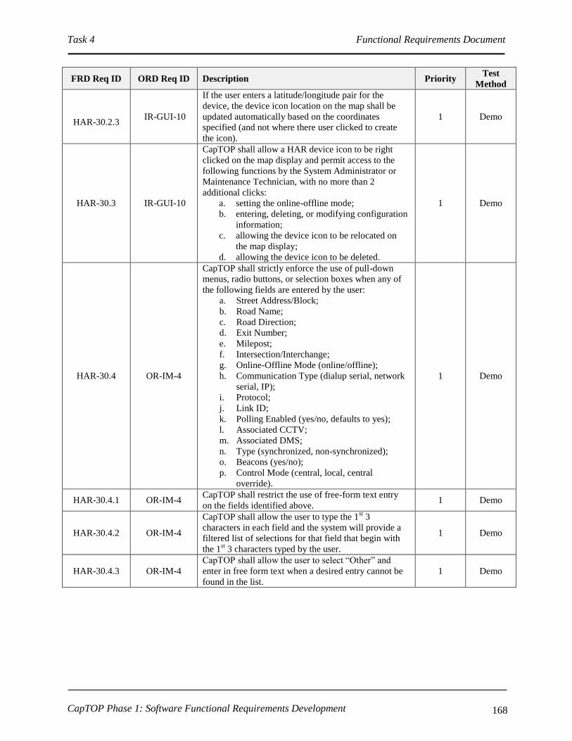
Task 4 Functional Requirements Document
CapTOP Phase 1: Software Functional Requirements Development 168
FRD Req ID ORD Req ID Description Priority Test
Method
HAR-30.2.3 IR-GUI-10
If the user enters a latitude/longitude pair for the
device, the device icon location on the map shall be
updated automatically based on the coordinates
specified (and not where there user clicked to create
the icon).
1 Demo
HAR-30.3 IR-GUI-10
CapTOP shall allow a HAR device icon to be right
clicked on the map display and permit access to the
following functions by the System Administrator or
Maintenance Technician, with no more than 2
additional clicks:
a. setting the online-offline mode;
b. entering, deleting, or modifying configuration
information;
c. allowing the device icon to be relocated on
the map display;
d. allowing the device icon to be deleted.
1 Demo
HAR-30.4 OR-IM-4
CapTOP shall strictly enforce the use of pull-down
menus, radio buttons, or selection boxes when any of
the following fields are entered by the user:
a. Street Address/Block;
b. Road Name;
c. Road Direction;
d. Exit Number;
e. Milepost;
f. Intersection/Interchange;
g. Online-Offline Mode (online/offline);
h. Communication Type (dialup serial, network
serial, IP);
i. Protocol;
j. Link ID;
k. Polling Enabled (yes/no, defaults to yes);
l. Associated CCTV;
m. Associated DMS;
n. Type (synchronized, non-synchronized);
o. Beacons (yes/no);
p. Control Mode (central, local, central
override).
1 Demo
HAR-30.4.1 OR-IM-4 CapTOP shall restrict the use of free-form text entry
on the fields identified above. 1 Demo
HAR-30.4.2 OR-IM-4
CapTOP shall allow the user to type the 1st 3
characters in each field and the system will provide a
filtered list of selections for that field that begin with
the 1st 3 characters typed by the user.
1 Demo
HAR-30.4.3 OR-IM-4
CapTOP shall allow the user to select “Other” and
enter in free form text when a desired entry cannot be
found in the list.
1 Demo

Task 4 Functional Requirements Document
CapTOP Phase 1: Software Functional Requirements Development 169
3.7.2.2.2 Monitoring HAR Status
FRD Req ID ORD Req ID Description Priority Test
Method
HAR-40
OR-DOC-1,
OR-DOC-23,
IR-GUI-16
CapTOP shall allow the TMC Operator to retrieve and
display the following operational status and
operational data for any HAR, subject to operator
privilege level:
a. Controller ID;
b. Online-offline mode ( static – set by System
Administrator or Maintenance Technician);
c. Communication status (OK, failed);
d. Control mode (central, local, central override);
e. Lock status (username if locked, if
implemented);
f. Transmitter status (on/off);
g. Recording status;
I. Slot No.;
II. Clip Name;
III. Length (in seconds).
h. Recording capacity status;
I. Total recording time capacity of
HAR;
II. Recording time used;
III. Recording time available.
i. Last contact (date/time);
j. Last communication status change (date/time);
k. Alarm status.
C Demo
HAR-40.1 OR-DOC-1
CapTOP shall use data from the following sources to
determine operational status:
a. data reported from the HAR;
b. data gained by CapTOP in attempts to
communicate with the HAR;
c. online/offline information entered manually
by authorized CapTOP users.
C Demo
HAR-50
SR-SYS-2,
IR-GUI-29,
IR-GUI-36,
IR-GUI-26
CapTOP shall allow users to simultaneously view
HAR status, which is refreshed automatically by the
system based on the polling interval, using the
following methods:
a. Color coded icons on the map display;
b. Via the HAR status window which lists all
HARs, the Controller ID, location, online-
offline mode, communication status, and
controller status.
C Demo
HAR-50.1 IR-GUI-28,
IR-GUI-26
CapTOP shall use the following colors for device icon
states:
a. Green=online;
b. Green with Yellow in middle = online and
message recording being broadcast;
c. Black with Yellow in middle = online,
locked, and message recording being
broadcast (if locking implemented);
d. Red = device failure;
e. Yellow = communication failure;
f. Gray = offline;
C Demo

Task 4 Functional Requirements Document
CapTOP Phase 1: Software Functional Requirements Development 170
FRD Req ID ORD Req ID Description Priority Test
Method
g. Brown = partial operation or recent failure.
HAR-50.1.1 IR-GUI-28,
IR-GUI-26
CapTOP shall use the following rules for device icon
states:
a. If the device is online but in communication
failure, the device icon color should be that of
a device with a communication failure;
b. In order for the device icon to be green, the
device must be both online and have OK
communication.
C Demo
HAR-50.2 IR-GUI-29
The refresh rate for the status of the icons and for the
data in the status window shall be configurable and
based upon the polling rate.
1 Demo
HAR-50.3 IR-GUI-31
CapTOP shall allow the user to obtain summary status
information (refer to HAR-40 for the list of fields) by
hovering over a HAR icon.
1 Demo
HAR-50.4 IR-GUI-29
CapTOP shall allow the user to select on any HAR in
the HAR status window (refer to HAR-50 item b) and
view all details (full status, configuration information,
and HAR controls) pertaining to that HAR.
1 Demo
HAR-60
SR-SYS-2,
IR-GUI-29,
IR-GUI-31,
IR-GUI-32
CapTOP shall provide a menu option to search for a
HAR by the following methods:
a. by device ID;
b. by IP address/drop address/channel ID/phone
number;
c. by street name;
d. by geographical address;
e. by intersection/interchange.
1 Demo
HAR-60.1 IR-GUI-32
CapTOP shall allow the TMC Operator to search for
HARs using a rubber-band style box on the map
display to search an area.
1 Demo
HAR-60.2 IR-GUI-32 The result of each search shall be a list of HARs that
are sorted, by default, by device ID. 1 Demo
HAR-60.3 IR-GUI-32
The result of each search shall be a list of HARs
sortable by device ID, IP address/drop address/channel
ID/phone number, street name, geographical address,
and intersection/interchange.
1 Demo
HAR-70 IR-GUI-13
CapTOP shall provide a monitoring and control
interface through communication servers for managing
all HARs.
C Demo
HAR-70.1
OR-DOC-3,
OR-TDCA-6,
OR-DOC-25,
SR-SYS-8,
SR-SYS-23
CapTOP shall provide a monitor and control interface
to all HARs conforming to the existing HAR’s native
Quixote DR1500 protocol.
C Demo
HAR-70.1.1
OR-DOC-2,
OR-DOC-3,
IR-GUI-29
CapTOP shall support a polling interval range from 0
to 99999 seconds, where zero indicates no polling. 1 Demo
HAR-70.2 IR-GUI-13
CapTOP shall be able to request HAR status and
obtain status response data through the monitoring and
control interface.
C Demo
HAR-70.3 IR-GUI-13
CapTOP shall be able to issue control commands and
receive status response through the monitoring and
control interface.
C Demo

Task 4 Functional Requirements Document
CapTOP Phase 1: Software Functional Requirements Development 171
FRD Req ID ORD Req ID Description Priority Test
Method
HAR-70.4 IR-GUI-17
CapTOP shall be capable of communicating to HAR
devices using the following physical communication
media:
a. regular telephone lines;
b. wireless connections (CDMA/GPRS and
other modems);
c. network connections.
C Demo
HAR-80 UR-TO-25
CapTOP shall provide the TMC Operator and the
Maintenance Technician the ability to monitor the
status of the following:
a. HAR device status (refer to HAR-40);
b. HAR events and alarm logs;
c. HAR online-offline mode;
d. Control mode (central, local, central
override);
e. Communication status (OK, failed).
C Demo
HAR-90 OR-C2F-2,
OR-DWA-13
CapTOP shall be able to store HAR operational status
and operational data (refer to HAR-40) in the CapTOP
operations database.
1 Demo
HAR-90.1 OR-C2F-2,
OR-DWA-13
CapTOP shall be able to store HAR equipment status
on state transitions. 1 Demo
HAR-100 OR-TDCA-20
CapTOP shall be able to, at the System
Administrator’s or Maintenance Technician’s request,
upload and display all configuration data available
from the HAR field controller/receiver.
1 Demo
HAR-110 OR-TDCA-21
CapTOP shall be able to, at the System
Administrator’s or Maintenance Technician’s request,
upload and store all configuration data in the CapTOP
central system device configuration database for HAR.
1 Demo
HAR-120 OR-TDCA-22
CapTOP shall be able to, at the System
Administrator’s or Maintenance Technician’s request,
download all configuration data from the CapTOP
central system device configuration database to the
HAR field controller/receiver.
1 Demo
3.7.2.2.3 HAR Control Commands
FRD Req ID ORD Req ID Description Priority Test
Method
HAR-130 OR-DOC-26
CapTOP shall allow the TMC Operator to select a
HAR and view a list of the defined recordings for each
HAR through the CapTOP GUI.
C Demo
HAR-130.1 OR-DOC-26
CapTOP shall provide the TMC Operator the ability to
select HAR recordings from the central system’s
library of messages, subject to privilege level, based on
the following:
a. type of HAR;
b. location of HAR;
c. type of incident;
d. type of special event;
e. severity of incident;
f. size of special event.
C Demo
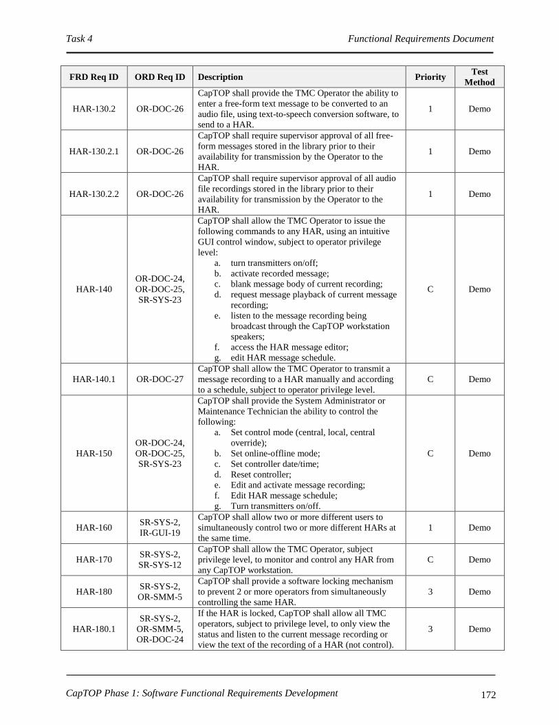
Task 4 Functional Requirements Document
CapTOP Phase 1: Software Functional Requirements Development 172
FRD Req ID ORD Req ID Description Priority Test
Method
HAR-130.2 OR-DOC-26
CapTOP shall provide the TMC Operator the ability to
enter a free-form text message to be converted to an
audio file, using text-to-speech conversion software, to
send to a HAR.
1 Demo
HAR-130.2.1 OR-DOC-26
CapTOP shall require supervisor approval of all free-
form messages stored in the library prior to their
availability for transmission by the Operator to the
HAR.
1 Demo
HAR-130.2.2 OR-DOC-26
CapTOP shall require supervisor approval of all audio
file recordings stored in the library prior to their
availability for transmission by the Operator to the
HAR.
1 Demo
HAR-140
OR-DOC-24,
OR-DOC-25,
SR-SYS-23
CapTOP shall allow the TMC Operator to issue the
following commands to any HAR, using an intuitive
GUI control window, subject to operator privilege
level:
a. turn transmitters on/off;
b. activate recorded message;
c. blank message body of current recording;
d. request message playback of current message
recording;
e. listen to the message recording being
broadcast through the CapTOP workstation
speakers;
f. access the HAR message editor;
g. edit HAR message schedule.
C Demo
HAR-140.1 OR-DOC-27
CapTOP shall allow the TMC Operator to transmit a
message recording to a HAR manually and according
to a schedule, subject to operator privilege level.
C Demo
HAR-150
OR-DOC-24,
OR-DOC-25,
SR-SYS-23
CapTOP shall provide the System Administrator or
Maintenance Technician the ability to control the
following:
a. Set control mode (central, local, central
override);
b. Set online-offline mode;
c. Set controller date/time;
d. Reset controller;
e. Edit and activate message recording;
f. Edit HAR message schedule;
g. Turn transmitters on/off.
C Demo
HAR-160 SR-SYS-2,
IR-GUI-19
CapTOP shall allow two or more different users to
simultaneously control two or more different HARs at
the same time.
1 Demo
HAR-170 SR-SYS-2,
SR-SYS-12
CapTOP shall allow the TMC Operator, subject
privilege level, to monitor and control any HAR from
any CapTOP workstation.
C Demo
HAR-180 SR-SYS-2,
OR-SMM-5
CapTOP shall provide a software locking mechanism
to prevent 2 or more operators from simultaneously
controlling the same HAR.
3 Demo
HAR-180.1
SR-SYS-2,
OR-SMM-5,
OR-DOC-24
If the HAR is locked, CapTOP shall allow all TMC
operators, subject to privilege level, to only view the
status and listen to the current message recording or
view the text of the recording of a HAR (not control).
3 Demo
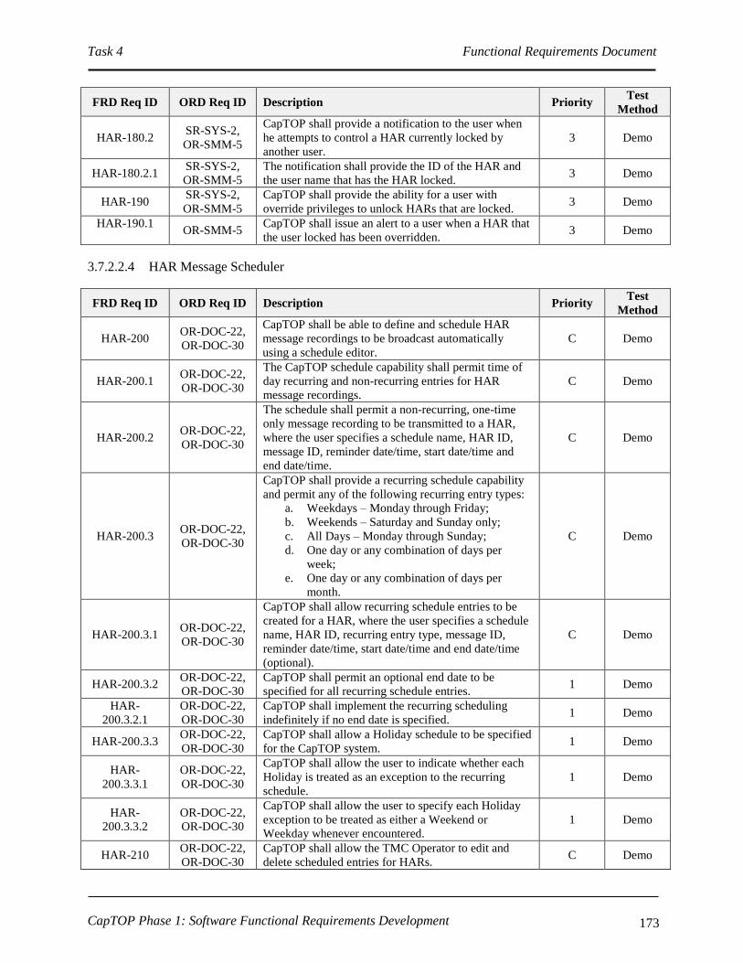
Task 4 Functional Requirements Document
CapTOP Phase 1: Software Functional Requirements Development 173
FRD Req ID ORD Req ID Description Priority Test
Method
HAR-180.2 SR-SYS-2,
OR-SMM-5
CapTOP shall provide a notification to the user when
he attempts to control a HAR currently locked by
another user.
3 Demo
HAR-180.2.1 SR-SYS-2,
OR-SMM-5
The notification shall provide the ID of the HAR and
the user name that has the HAR locked. 3 Demo
HAR-190 SR-SYS-2,
OR-SMM-5
CapTOP shall provide the ability for a user with
override privileges to unlock HARs that are locked. 3 Demo
HAR-190.1
OR-SMM-5
CapTOP shall issue an alert to a user when a HAR that
the user locked has been overridden. 3 Demo
3.7.2.2.4 HAR Message Scheduler
FRD Req ID ORD Req ID Description Priority Test
Method
HAR-200 OR-DOC-22,
OR-DOC-30
CapTOP shall be able to define and schedule HAR
message recordings to be broadcast automatically
using a schedule editor.
C Demo
HAR-200.1 OR-DOC-22,
OR-DOC-30
The CapTOP schedule capability shall permit time of
day recurring and non-recurring entries for HAR
message recordings.
C Demo
HAR-200.2 OR-DOC-22,
OR-DOC-30
The schedule shall permit a non-recurring, one-time
only message recording to be transmitted to a HAR,
where the user specifies a schedule name, HAR ID,
message ID, reminder date/time, start date/time and
end date/time.
C Demo
HAR-200.3 OR-DOC-22,
OR-DOC-30
CapTOP shall provide a recurring schedule capability
and permit any of the following recurring entry types:
a. Weekdays – Monday through Friday;
b. Weekends – Saturday and Sunday only;
c. All Days – Monday through Sunday;
d. One day or any combination of days per
week;
e. One day or any combination of days per
month.
C Demo
HAR-200.3.1 OR-DOC-22,
OR-DOC-30
CapTOP shall allow recurring schedule entries to be
created for a HAR, where the user specifies a schedule
name, HAR ID, recurring entry type, message ID,
reminder date/time, start date/time and end date/time
(optional).
C Demo
HAR-200.3.2 OR-DOC-22,
OR-DOC-30
CapTOP shall permit an optional end date to be
specified for all recurring schedule entries. 1 Demo
HAR-
200.3.2.1
OR-DOC-22,
OR-DOC-30
CapTOP shall implement the recurring scheduling
indefinitely if no end date is specified. 1 Demo
HAR-200.3.3 OR-DOC-22,
OR-DOC-30
CapTOP shall allow a Holiday schedule to be specified
for the CapTOP system. 1 Demo
HAR-
200.3.3.1
OR-DOC-22,
OR-DOC-30
CapTOP shall allow the user to indicate whether each
Holiday is treated as an exception to the recurring
schedule.
1 Demo
HAR-
200.3.3.2
OR-DOC-22,
OR-DOC-30
CapTOP shall allow the user to specify each Holiday
exception to be treated as either a Weekend or
Weekday whenever encountered.
1 Demo
HAR-210 OR-DOC-22,
OR-DOC-30
CapTOP shall allow the TMC Operator to edit and
delete scheduled entries for HARs. C Demo

Task 4 Functional Requirements Document
CapTOP Phase 1: Software Functional Requirements Development 174
3.7.2.2.5 Reports
FRD Req ID ORD Req ID Description Priority Test
Method
HAR-220 OR-DOC-22,
OR-DOC-30
CapTOP shall allow the TMC Operator to produce a
report of all scheduled entries for an individual HAR
or all HARs.
2 Demo
HAR-220.1 OR-DOC-22,
OR-DOC-30
The report shall list all schedule entries, and shall
contain the following:
a. Schedule name;
b. HAR ID or Group ID;
c. Message ID;
d. Recurrent entry type (optional);
e. State Date/Time;
f. End Date/Time (optional).
2 Demo
HAR-230
SR-SYS-22,
SR-SYS-36,
OR-DOC-4,
IR-GUI-8
CapTOP shall be able to automatically generate real-
time tabular reports that show the real-time operational
status and operational data of all HARs.
2 Demo
HAR-240
SR-SYS-22,
SR-SYS-36,
OR-DOC-4,
IR-GUI-8
CapTOP shall provide the following information in the
HAR status report:
a. HAR ID;
b. Location;
c. Online-offline mode
d. Locked or unlocked status with user name (if
implemented);
e. Communication status (OK, failed);
f. Control mode (central, local, central
override);
g. Message ID being broadcast;
h. Alarm status.
2 Demo
HAR-250 OR-DWA-7
CapTOP shall be able to produce the following
performance reports for evaluating the performance of
HARs, using data in the CapTOP operations and
archived databases:
a. Number of times a HAR transitioned from
online to offline over a specified time period;
b. Number of times a HAR transitioned from no
device failure to device failure over a
specified time period;
c. Number of times a HAR transitioned from no
communication failure to communication
failure over a specified time period.
2 Demo
HAR-260
SR-SYS-22,
SR-SYS-36,
OR-DOC-4,
IR-GUI-8
CapTOP shall be able to display and print the
following reports:
a. For a user entered HAR ID, provide a
message recording history report, consisting
of the HAR ID, message ID, date/time
transmitted, and username who transmitted
the message.
b. For a user entered user ID, provide a message
recording history report, consisting of the
User ID, HAR ID, message ID, and date/time
transmitted.
2 Demo
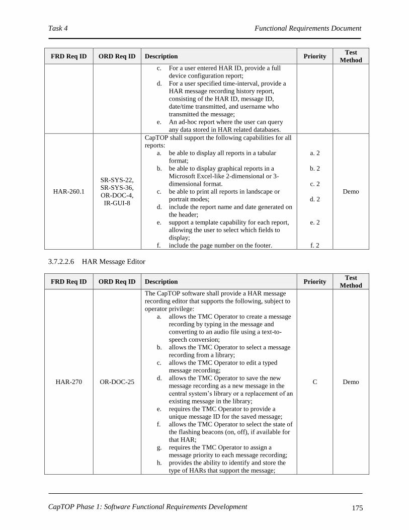
Task 4 Functional Requirements Document
CapTOP Phase 1: Software Functional Requirements Development 175
FRD Req ID ORD Req ID Description Priority Test
Method
c. For a user entered HAR ID, provide a full
device configuration report;
d. For a user specified time-interval, provide a
HAR message recording history report,
consisting of the HAR ID, message ID,
date/time transmitted, and username who
transmitted the message;
e. An ad-hoc report where the user can query
any data stored in HAR related databases.
HAR-260.1
SR-SYS-22,
SR-SYS-36,
OR-DOC-4,
IR-GUI-8
CapTOP shall support the following capabilities for all
reports:
a. be able to display all reports in a tabular
format;
b. be able to display graphical reports in a
Microsoft Excel-like 2-dimensional or 3-
dimensional format.
c. be able to print all reports in landscape or
portrait modes;
d. include the report name and date generated on
the header;
e. support a template capability for each report,
allowing the user to select which fields to
display;
f. include the page number on the footer.
a. 2
b. 2
c. 2
d. 2
e. 2
f. 2
Demo
3.7.2.2.6 HAR Message Editor
FRD Req ID ORD Req ID Description Priority Test
Method
HAR-270 OR-DOC-25
The CapTOP software shall provide a HAR message
recording editor that supports the following, subject to
operator privilege:
a. allows the TMC Operator to create a message
recording by typing in the message and
converting to an audio file using a text-to-
speech conversion;
b. allows the TMC Operator to select a message
recording from a library;
c. allows the TMC Operator to edit a typed
message recording;
d. allows the TMC Operator to save the new
message recording as a new message in the
central system’s library or a replacement of an
existing message in the library;
e. requires the TMC Operator to provide a
unique message ID for the saved message;
f. allows the TMC Operator to select the state of
the flashing beacons (on, off), if available for
that HAR;
g. requires the TMC Operator to assign a
message priority to each message recording;
h. provides the ability to identify and store the
type of HARs that support the message;
C Demo
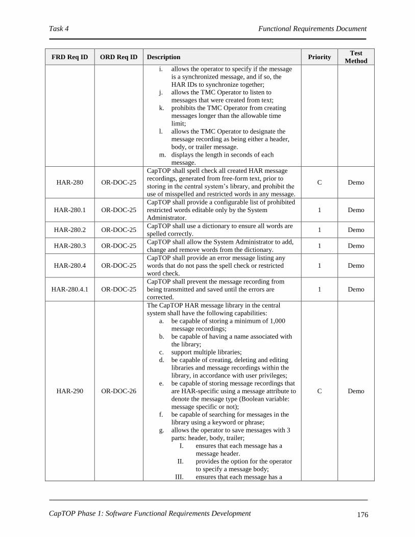
Task 4 Functional Requirements Document
CapTOP Phase 1: Software Functional Requirements Development 176
FRD Req ID ORD Req ID Description Priority Test
Method
i. allows the operator to specify if the message
is a synchronized message, and if so, the
HAR IDs to synchronize together;
j. allows the TMC Operator to listen to
messages that were created from text;
k. prohibits the TMC Operator from creating
messages longer than the allowable time
limit;
l. allows the TMC Operator to designate the
message recording as being either a header,
body, or trailer message.
m. displays the length in seconds of each
message.
HAR-280 OR-DOC-25
CapTOP shall spell check all created HAR message
recordings, generated from free-form text, prior to
storing in the central system’s library, and prohibit the
use of misspelled and restricted words in any message.
C Demo
HAR-280.1 OR-DOC-25
CapTOP shall provide a configurable list of prohibited
restricted words editable only by the System
Administrator.
1 Demo
HAR-280.2 OR-DOC-25 CapTOP shall use a dictionary to ensure all words are
spelled correctly. 1 Demo
HAR-280.3 OR-DOC-25 CapTOP shall allow the System Administrator to add,
change and remove words from the dictionary. 1 Demo
HAR-280.4 OR-DOC-25
CapTOP shall provide an error message listing any
words that do not pass the spell check or restricted
word check.
1 Demo
HAR-280.4.1 OR-DOC-25
CapTOP shall prevent the message recording from
being transmitted and saved until the errors are
corrected.
1 Demo
HAR-290 OR-DOC-26
The CapTOP HAR message library in the central
system shall have the following capabilities:
a. be capable of storing a minimum of 1,000
message recordings;
b. be capable of having a name associated with
the library;
c. support multiple libraries;
d. be capable of creating, deleting and editing
libraries and message recordings within the
library, in accordance with user privileges;
e. be capable of storing message recordings that
are HAR-specific using a message attribute to
denote the message type (Boolean variable:
message specific or not);
f. be capable of searching for messages in the
library using a keyword or phrase;
g. allows the operator to save messages with 3
parts: header, body, trailer;
I. ensures that each message has a
message header.
II. provides the option for the operator
to specify a message body;
III. ensures that each message has a
C Demo

Task 4 Functional Requirements Document
CapTOP Phase 1: Software Functional Requirements Development 177
FRD Req ID ORD Req ID Description Priority Test
Method
message trailer.
h. be capable of storing message recordings
applicable to multiple HAR types;
i. be capable of storing the message recordings
in text format;
j. be capable of storing the message recordings
in an audio file format;
k. allow the TMC Operator to delete message
recordings, one at a time, in accordance with
user privileges;
l. allow the TMC Operator to delete all message
recordings in one command in accordance
with user privileges;
m. allow the TMC Operator to select multiple
message recordings and delete them in one
command, in accordance with user privileges.
HAR-300 OR-DOC-26,
OR-DOC-28
CapTOP shall allow the same message recording to be
sent to multiple HARs of the same type using a drag
and drop capability, in accordance with user privileges.
1 Demo
HAR-310 OR-DOC-26,
OR-DOC-28
CapTOP shall allow the same message recording to be
sent to multiple HARs of the same type using a
multiple selection capability, in accordance with user
privileges.
1 Demo
HAR-320 OR-DOC-27 CapTOP shall notify the TMC Operator of any failed
message transmissions. 1 Demo
HAR-330 OR-DOC-31
CapTOP shall take no longer than 120 seconds after
initiation of message transmission to update message
recording on the HAR and receive confirmation the
message recording was posted via the communication
protocol.
1 Demo
HAR-340
OR-DOC-31,
SR-SYS-24,
IR-GUI-29
CapTOP shall take no longer than 60 seconds after
receipt of confirmation of message posting or failure to
update the status of the HAR within the system.
1 Demo
HAR-350 OR-DOC-25,
SR-SYS-23
CapTOP shall allow the TMC Operator to specify a
value for an optional parameter called “maximum
recorded message duration”, represented in seconds
from 0-9,999,999, with a default value of 90 seconds.
1 Demo
HAR-350.1 OR-DOC-26
CapTOP shall provide a parameter that specifies the
maximum length of each recorded message body, and
shall be set to a default value of 60 seconds.
1 Demo
HAR-350.2 OR-DOC-26
CapTOP shall provide a parameter that specifies the
maximum length of each recorded message header,
and shall be set to a default value of 15 seconds.
1 Demo
HAR-350.3 OR-DOC-26
CapTOP shall provide a parameter that specifies the
maximum length of each recorded message trailer, and
shall be set to a default value of 15 seconds.
1 Demo
HAR-360 OR-DOC-25,
SR-SYS-23
CapTOP shall require each recorded message begin
with a header that announces DDOT as the owning
agency and the station call symbols.
1 Demo
HAR-360.1 OR-DOC-25,
SR-SYS-23
CapTOP shall prohibit the message header and station
call symbols from being deleted or turned off while the
HAR transmitter is on, due to FCC regulations.
1 Demo
HAR-370 OR-DOC-26 CapTOP shall be able to manage a HAR inventory of 1 Demo

Task 4 Functional Requirements Document
CapTOP Phase 1: Software Functional Requirements Development 178
FRD Req ID ORD Req ID Description Priority Test
Method
100 HARs.
HAR-380 OR-DOC-25,
SR-SYS-2
CapTOP shall manage recorded messages coming
from multiple operators and the system scheduler, and
shall prioritize all of these into a single list and shall
post the message recording with the highest priority.
1 Demo
HAR-380.1 OR-DOC-25
CapTOP shall have the ability to notify the TMC
Operator, TMC Manager, and Maintenance Manager
when there is a conflict with two or more message
recordings, of the same priority, attempting to be sent
out at the same time or within 5 minutes of one
another.
1 Demo
HAR-380.2 OR-DOC-25,
OR-SMM-5
CapTOP shall require a prompt and a TMC Operator
override whenever a lower priority message recording
is attempted to be transmitted while a higher priority
message recording is being broadcast.
1 Demo
HAR-390 OR-DOC-25
CapTOP shall provide subsystem parameters to
enable/disable the following:
a. flashing beacons are turned on after any
message recording is sent to a HAR;
b. flashing beacons are turned on only after
message recordings of designated priority are
sent to a HAR;
c. flashing beacons are always turned off after a
HAR message is blanked.
1 Demo
3.7.2.2.7 HAR Logging Requirements
FRD Req ID ORD Req ID Description Priority Test
Method
HAR-400 UR-TO-11,
OR-TOM-1
CapTOP shall store and time stamp all operator and
system activities that pertain to HARs and provide the
output in a time sequential log.
C Demo
HAR-400.1
UR-TO-11,
OR-C2F-3,
OR-C2F-4,
OR-DWA-13
CapTOP shall have the capability to automatically log
the following user activities to the log database that
pertain to HARs:
a. any operator-initiated action resulting in a
request to access information;
b. any operator-initiated action that attempts to,
or results in, a change to a HAR;
c. changes to the message library (new
messages, changes to existing messages;
deleted messages);
d. message transmission to a HAR;
e. when the user changes the HAR configuration
data;
f. operator login;
g. operator logout.
(Note: also refer to the LOG-* requirements).
C Demo
HAR-400.2 UR-TO-11
CapTOP shall have the capability to automatically log
the following system activities to the log database that
pertain to HARs:
a. any system-initiated action that attempts to, or
results in, a change to the device;
C Demo

Task 4 Functional Requirements Document
CapTOP Phase 1: Software Functional Requirements Development 179
FRD Req ID ORD Req ID Description Priority Test
Method
b. when the communication status changes (OK
to failed, and failed to OK);
c. changes in online-offline mode;
d. changes in control mode (central, local,
central override);
e. software application login;
f. software application logout;
g. software application errors;
h. database login;
i. database logout.
(Note: also refer to the LOG-* requirements).
HAR-400.3 UR-TO-11 CapTOP shall provide a window to display all logged
system and user activities for HARs. 1 Demo
HAR-400.4 UR-TO-11
CapTOP shall assign and store one of the following
action types when logging all HAR activities:
a. operator input;
b. operator command transmission;
c. operator informational message;
d. operator error;
e. system warning;
f. system error;
g. system information message;
h. software application warning;
i. software application error;
j. software application information message.
1 Demo
HAR-400.5 UR-TO-11
For log entries triggered by user actions, CapTOP shall
log the following:
a. Username;
b. Date stamp;
c. Time stamp;
d. Workstation ID;
e. Workstation IP address;
f. Action type;
g. Description of action (for message updates,
include the device ID, message ID and
summary status of HAR prior to
transmission).
1 Demo
HAR-400.6 UR-TO-11
For log entries generated by the CapTOP applications,
CapTOP shall log the following:
a. Application name;
b. Date stamp;
c. Time stamp;
d. Action type;
e. Description of action.
1 Demo
HAR-400.7 UR-TO-11 CapTOP shall make all log entries read-only,
changeable by only the System Administrator. 1 Demo
HAR-410 OR-DWA-5
CapTOP shall have the capability to query and retrieve
all operator actions/commands that pertain to HARs
from the log by filtering on the following:
a. Workstation ID;
b. Workstation IP address;
c. Username;
d. Date stamp;
1 Demo

Task 4 Functional Requirements Document
CapTOP Phase 1: Software Functional Requirements Development 180
FRD Req ID ORD Req ID Description Priority Test
Method
e. Time stamp;
f. Action type.
HAR-420 UR-TO-11,
OR-DDM-16
CapTOP shall be capable of generating a system alert
for the following:
a. changes in communication status (OK to
failed, and failed to OK);
b. changes in control mode (central, local,
central override);
c. changes in online-offline mode;
d. changes to HAR configuration data.
1 Demo
3.7.2.2.8 HAR Archiving Requirements
FRD Req ID ORD Req ID Description Priority Test
Method
HAR-430 OR-DWA-13
CapTOP shall have the capability to format and
perform automated and manually initiated migration of
logged data that pertains to HARs from the log
database to the archived database.
1 Demo
HAR-440 OR-DWA-13
CapTOP shall have the capability to format and
perform automated and manually initiated migration of
operations data that pertains to HARs from the
operations database to the archived database.
1 Demo
3.7.2.3 Traffic Signal Interface Requirements
3.7.2.3.1 Accessing the Traffic Signal System Interface
FRD Req ID ORD Req ID Description Priority Test
Method
SIG-10 OR-DOC-1
CapTOP shall allow the TMC Operator to access the
traffic signal status interface, subject to operator
privilege level.
C Demo
SIG-10.1 OR-DOC-1,
IR-GUI-52
CapTOP shall allow the TMC Operator to access the
traffic signal status interface, using the following
mechanisms:
a. Left clicking on a traffic signal icon on the
map display;
b. Left clicking on the traffic signal status
interface icon off the CapTOP toolbar;
c. Left clicking on the traffic signal status
interface menu off the CapTOP toolbar.
1 Demo
SIG-10.2 OR-SMM-5,
OR-DOC-1
CapTOP shall provide role-based privileges to control
access to the following, subject to the user’s privilege
level:
a. Traffic signal events and alarms;
b. Traffic signal status (refer to SIG-40.1.1 and
SIG-40.1.2).
C Demo

Task 4 Functional Requirements Document
CapTOP Phase 1: Software Functional Requirements Development 181
FRD Req ID ORD Req ID Description Priority Test
Method
SIG-20
IR-GUI-10,
IR-GUI-52,
IR-GUI-47
CapTOP shall display the following traffic signal icons
on a separate layer on the map-based display:
a. 170E Phase-Based controllers;
b. 170E Interval-Based controllers;
c. ATC controllers;
d. 170E reversible lane red X/green arrow
signals;
e. 170E reversible lane blank-out-signs.
1, item c
priority 2 Demo
SIG-20.1 IR-GUI-12 CapTOP shall allow the TMC Operator to turn on and
off the traffic signal layer on the map display. 1 Demo
SIG-20.2
IR-GUI-10,
IR-GUI-11,
IR-GUI-52
CapTOP shall allow a traffic signal device icon to be
left clicked on the map display by the TMC Operator,
subject to privilege level, and permit access to the
traffic signal status with no more than 2 clicks.
1 Demo
SIG-20.2.1 IR-GUI-10,
IR-GUI-11
CapTOP shall provide a dynamic window that shows
the traffic signal status for a particular controller, using
a graphical map of the intersection with the following
attributes:
a. Provides an accurate depiction of the
intersection in terms of geometry, number of
lanes, turning lanes, signal heads, and
approaches.
b. Provides real-time updates for the signal states
(red, yellow, green, turning arrows);
c. Provides access to detailed signal status in the
form of a tabular window (refer to SIG-
40.1.2);
d. Provides access to timing plan, interval data,
and phase data (refer to SIG-40.1.1) in the
form of a tabular window.
1 Demo
SIG-20.2.1.1 IR-GUI-10,
IR-GUI-11
CapTOP shall allow a minimum of 10 traffic signal
status controller windows to be viewed simultaneously
from a single CapTOP workstation.
1 Demo
SIG-20.3 IR-GUI-12 The icons used for the traffic signal icon layer shall be
unique from icons used in other layers. 1 Demo
SIG-30 IR-GUI-10
CapTOP shall provide the ability for the System
Administrator to add, delete, and modify traffic signal
devices from the CapTOP map display (also refer to
GUI-200*).
C Demo
SIG-30.1 IR-GUI-10
CapTOP shall allow the System Administrator to point
and click on a location on the map display to add a new
traffic signal icon using a pop-up menu.
1 Demo
SIG-30.2 IR-GUI-10
When a traffic signal device icon is added, CapTOP
shall prompt the System Administrator with a window
to enter all configuration data required to integrate the
device.
1 Demo
SIG-30.2.1
IR-GUI-10,
OR-TDCA-20,
OR-TDCA-21
CapTOP shall allow the following configuration data to
be entered for each traffic signal device to enable the
device to become operational in the system:
a. Controller ID;
b. ACISA Number;
c. Controller Type (170E or ATC);
d. Control Type (Interval or Phase);
1, ATC
portion of
item c
priority 2
Demo
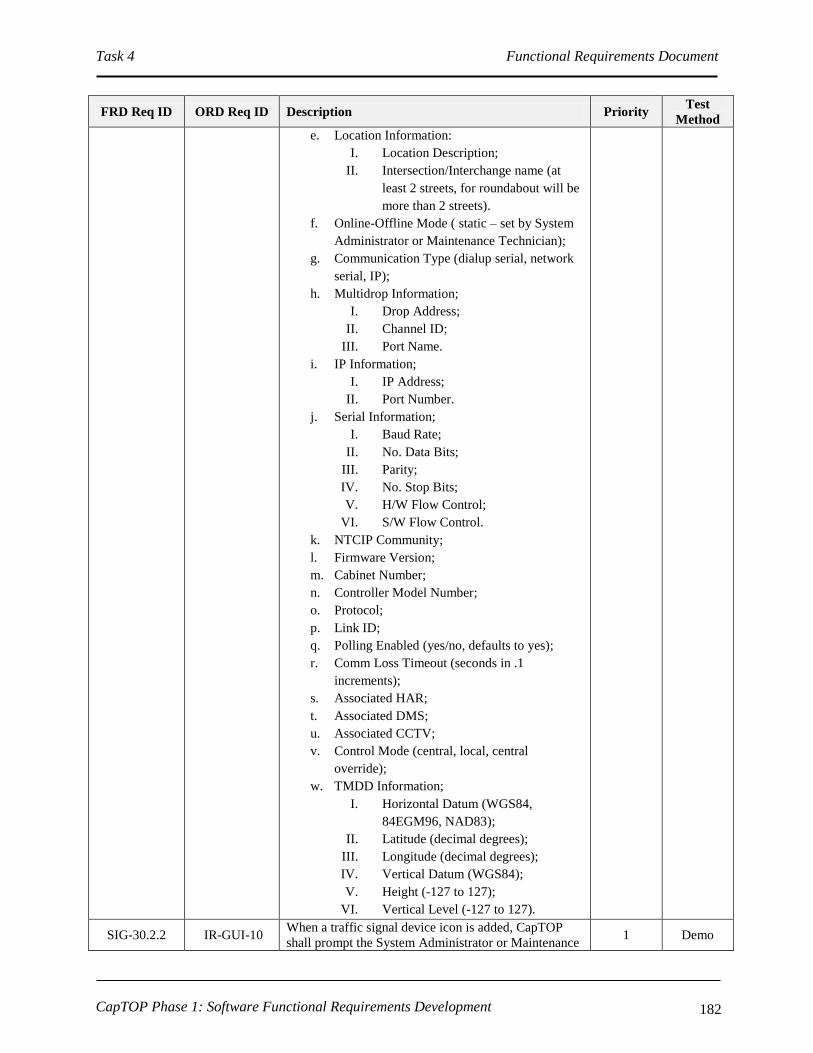
Task 4 Functional Requirements Document
CapTOP Phase 1: Software Functional Requirements Development 182
FRD Req ID ORD Req ID Description Priority Test
Method
e. Location Information:
I. Location Description;
II. Intersection/Interchange name (at
least 2 streets, for roundabout will be
more than 2 streets).
f. Online-Offline Mode ( static – set by System
Administrator or Maintenance Technician);
g. Communication Type (dialup serial, network
serial, IP);
h. Multidrop Information;
I. Drop Address;
II. Channel ID;
III. Port Name.
i. IP Information;
I. IP Address;
II. Port Number.
j. Serial Information;
I. Baud Rate;
II. No. Data Bits;
III. Parity;
IV. No. Stop Bits;
V. H/W Flow Control;
VI. S/W Flow Control.
k. NTCIP Community;
l. Firmware Version;
m. Cabinet Number;
n. Controller Model Number;
o. Protocol;
p. Link ID;
q. Polling Enabled (yes/no, defaults to yes);
r. Comm Loss Timeout (seconds in .1
increments);
s. Associated HAR;
t. Associated DMS;
u. Associated CCTV;
v. Control Mode (central, local, central
override);
w. TMDD Information;
I. Horizontal Datum (WGS84,
84EGM96, NAD83);
II. Latitude (decimal degrees);
III. Longitude (decimal degrees);
IV. Vertical Datum (WGS84);
V. Height (-127 to 127);
VI. Vertical Level (-127 to 127).
SIG-30.2.2 IR-GUI-10 When a traffic signal device icon is added, CapTOP
shall prompt the System Administrator or Maintenance 1 Demo

Task 4 Functional Requirements Document
CapTOP Phase 1: Software Functional Requirements Development 183
FRD Req ID ORD Req ID Description Priority Test
Method
Technician with setting the device online or offline.
SIG-30.2.3 IR-GUI-10
If the user enters a latitude/longitude pair for the
device, the device icon location on the map shall be
updated automatically based on the coordinates
specified (and not where there user clicked to create the
icon).
1 Demo
SIG-30.3
IR-GUI-10,
IR-GUI-11,
IR-GUI-44,
IR-GUI-45
CapTOP shall allow a traffic signal device icon to be
right clicked on the map display and permit access to
the following functions by the System Administrator or
Maintenance Technician, with no more than 2
additional clicks:
a. setting the online-offline mode;
b. entering, deleting, or modifying configuration
information;
c. allowing the device icon to be relocated on the
map display;
d. allowing the user to launch the QuicNet client
or the ATC software for signal control based
on controller type;
e. allowing the device icon to be deleted.
1, ATC
portion of
item d
priority 2
Demo
SIG-30.4 OR-IM-4
CapTOP shall strictly enforce the use of pull-down
menus, radio buttons, or selection boxes when any of
the following fields are entered by the user:
a. Intersection/Interchange.
b. Controller Type (170E or ATC);
c. Control Type (Interval or Phase);
d. Online-Offline Mode (online/offline);
e. Communication Type (dialup serial, network
serial, IP);
f. Link ID;
g. Polling Enabled (yes/no, defaults to yes);
h. Associated HAR;
i. Associated DMS;
j. Associated CCTV;
k. Control Mode (central, local, central
override).
1, ATC
portion of
item d
priority 2
Demo
SIG-30.4.1 OR-IM-4 CapTOP shall restrict the use of free-form text entry on
the fields identified above. 1 Demo
SIG-30.4.2 OR-IM-4
CapTOP shall allow the user to type the 1st 3 characters
in each field and the system will provide a filtered list
of selections for that field that begin with the 1st 3
characters typed by the user.
2 Demo
SIG-30.4.3 OR-IM-4
CapTOP shall allow the user to select “Other” and
enter in free form text when a desired entry cannot be
found in the list.
1 Demo

Task 4 Functional Requirements Document
CapTOP Phase 1: Software Functional Requirements Development 184
3.7.2.3.2 Monitoring Traffic Signal Status
FRD Req ID ORD Req ID Description Priority Test
Method
SIG-40
OR-DOC-10,
IR-GUI-14,
IR-GUI-16,
IR-GUI-47
CapTOP shall support the monitoring of five (5) types
of traffic signal and reversible lane controllers:
a. 170E phase-based signal controller;
b. 170E interval-based signal controller;
c. ATC phase-based signal controller;
d. 170E reversible lane controller using red X
and green arrow signals;
e. 170E reversible lane controller using blank-
out-signs.
C,item c
priority 2 Demo
SIG-40.1
SR-SYS-22,
SR-SYS-36,
OR-DOC-4,
IR-GUI-8, IR-
GUI-14, IR-
GUI-16,OR-
DOC-6, OR-
DOC-7,
OR-DOC-10,
IR-GUI-44,
IR-GUI-47,
IR-GUI-45,
IR-GUI-52
CapTOP shall support data acquisition from the Traffic
Signal System to support operational status
monitoring.
C Demo
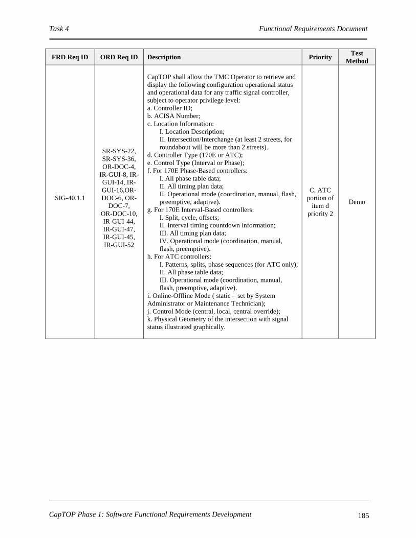
Task 4 Functional Requirements Document
CapTOP Phase 1: Software Functional Requirements Development 185
FRD Req ID ORD Req ID Description Priority Test
Method
SIG-40.1.1
SR-SYS-22,
SR-SYS-36,
OR-DOC-4,
IR-GUI-8, IR-
GUI-14, IR-
GUI-16,OR-
DOC-6, OR-
DOC-7,
OR-DOC-10,
IR-GUI-44,
IR-GUI-47,
IR-GUI-45,
IR-GUI-52
CapTOP shall allow the TMC Operator to retrieve and
display the following configuration operational status
and operational data for any traffic signal controller,
subject to operator privilege level:
a. Controller ID;
b. ACISA Number;
c. Location Information:
I. Location Description;
II. Intersection/Interchange (at least 2 streets, for
roundabout will be more than 2 streets).
d. Controller Type (170E or ATC);
e. Control Type (Interval or Phase);
f. For 170E Phase-Based controllers:
I. All phase table data;
II. All timing plan data;
II. Operational mode (coordination, manual, flash,
preemptive, adaptive).
g. For 170E Interval-Based controllers:
I. Split, cycle, offsets;
II. Interval timing countdown information;
III. All timing plan data;
IV. Operational mode (coordination, manual,
flash, preemptive).
h. For ATC controllers:
I. Patterns, splits, phase sequences (for ATC only);
II. All phase table data;
III. Operational mode (coordination, manual,
flash, preemptive, adaptive).
i. Online-Offline Mode ( static – set by System
Administrator or Maintenance Technician);
j. Control Mode (central, local, central override);
k. Physical Geometry of the intersection with signal
status illustrated graphically.
C, ATC
portion of
item d
priority 2
Demo

Task 4 Functional Requirements Document
CapTOP Phase 1: Software Functional Requirements Development 186
FRD Req ID ORD Req ID Description Priority Test
Method
SIG-40.1.2
SR-SYS-22,
SR-SYS-36,
OR-DOC-4,
IR-GUI-8, IR-
GUI-14, IR-
GUI-16,OR-
DOC-6, OR-
DOC-7,
OR-DOC-10,
IR-GUI-44,
IR-GUI-47,
IR-GUI-45,
IR-GUI-52
CapTOP shall allow the TMC Operator to retrieve and
display the following dynamic operational status and
operational data for any traffic signal controller,
subject to operator privilege level:
a. Controller ID;
b. Controller Type (170E or ATC);
c. Control Type (Interval or Phase);
d. For 170E Phase-Based controllers:
I. Current phase status (red, yellow, green for each
phase on each approach);
II. Current timing plan in effect;
III. Operational mode (coordination, manual,
flash, preemptive, adaptive).
e. For 170E Interval-Based controllers:
I. Current signal status (red, yellow, green) for
each interval for each approach;
II. Interval timing countdown information;
III. Current timing plan in effect;
IV. Operational mode (coordination, manual,
flash, preemptive).
f. For ATC controllers:
I. Current signal status (red, yellow, green) for
each phase on each approach;
II. Detection malfunction status;
III. Operational mode (coordination, manual,
flash, preemptive, adaptive);
IV. UPS status (OK, failed);
V. Battery voltage;
VI. Battery status (normal, low voltage).
g. For 170E controllers with reversible lane red
X/green arrow signals:
I. Red X and green arrow signal status.
h. For 170E controllers with reversible lane blank-out-
signs:
I. blank-out-sign status.
i. Online-Offline Mode ( static – set by System
Administrator or Maintenance Technician);
j. Controller Status (OK, failed);
k. Communication Status (OK, failed);
l. Control Mode (central, local, central override);
m. Current Signal Status of the pedestrian signal;
n. Alarm Status;
C, ATC
portion of
item d
priority 2
Demo
SIG-40.2 OR-DOC-1
CapTOP shall be able to monitor all traffic signals by
interfacing with the Traffic Signal System to determine
their operational status.
C Demo
SIG-40.2.1 IR-GUI-14 CapTOP shall prohibit traffic signal controller changes
through this interface. C Demo
SIG-40.2.2
OR-DOC-2,
OR-DOC-3,
IR-GUI-29
CapTOP shall support a polling interval range from 0
to 99999 seconds, where zero indicates no polling. 1 Demo

Task 4 Functional Requirements Document
CapTOP Phase 1: Software Functional Requirements Development 187
FRD Req ID ORD Req ID Description Priority Test
Method
SIG-40.2.3 IR-GUI-14,
IR-GUI-44
CapTOP shall be able to request 170E traffic signal
status and obtain status response data through the
traffic signal status interface on the existing QuicNet
signal server.
C Demo
SIG-40.2.3.1 OR-DOC-3
CapTOP shall interface with QuicNet 170E Traffic
Signal System in accordance with the QuicNet API
(refer to the “Washington DC Data Interface to
QuicNet/4, version 2.0” document revised on
2/26/2009, or the latest available revision, that
correlates with DDOT’s current software) to access
traffic signal status for 170E-based intersections.
C Demo
SIG-40.2.4 IR-GUI-14
CapTOP shall be able to request ATC traffic signal
status and obtain status response data through the
traffic signal status interface on the future ATC signal
server.
2 Demo
SIG-40.2.4.1 OR-DOC-3
CapTOP shall interface with ATC Traffic Signal
System in accordance with the future ATC Signal
System API (to be published) to access traffic signal
status for ATC-based intersections.
2 Demo
SIG-40.3 OR-DOC-1
CapTOP shall use data from the following sources to
determine operational status:
a. data reported from the Traffic Signal System;
b. data gained by CapTOP in attempts to
communicate with the Traffic Signal System;
c. online/offline information entered manually
by authorized CapTOP users.
C Demo
SIG-60
SR-SYS-2,
IR-GUI-36,
IR-GUI-26
CapTOP shall allow users to simultaneously view
traffic signal status, which is refreshed automatically
by the system based on the polling interval, using the
following methods:
a. Color coded icons on the map display (refer
to SIG-20.2);
b. Via the traffic signal summary status window
which lists all traffic signals, the Controller
ID, ACISA number, location, online-offline
mode, communication status, and controller
status.
C Demo
SIG-60.1
IR-GUI-28,
IR-GUI-26,
OR-EM-7
CapTOP shall use the following colors for device icon
states:
a. Solid Green = online and cycling;
b. Solid Yellow = online and flashing signals;
c. Solid Red = offline;
d. Orange = device failure;
e. Brown = communication failure.
C Demo
SIG-60.1.1
IR-GUI-28,
IR-GUI-26,
OR-EM-7
CapTOP shall use the following rules for device icon
states:
a. If the device is online but in communication
failure, the device icon color should be that of
a device with a communication failure;
b. In order for the device icon to be green, the
device must be both online and have OK
communication.
1 Demo

Task 4 Functional Requirements Document
CapTOP Phase 1: Software Functional Requirements Development 188
FRD Req ID ORD Req ID Description Priority Test
Method
SIG-60.2 IR-GUI-31,
IR-GUI-29
The refresh rate for the status of the icons on the map
display and for the data in the traffic signal summary
status window shall be configurable and based upon
the polling rate.
1 Demo
SIG-60.3 IR-GUI-31
CapTOP shall allow the user to obtain summary status
information (refer to SIG-60.b for the list of fields) by
hovering over a traffic signal controller icon.
1 Demo
SIG-60.4 IR-GUI-31
The traffic signal summary status window shall allow
the user to click on an individual row and access the
detailed traffic signal status and configuration
information for a particular controller (refer to SIG-
60).
C Demo
SIG-70
SR-SYS-2,
IR-GUI-31,
IR-GUI-32
CapTOP shall provide a menu option to search for a
traffic signal by the following methods:
a. by controller ID;
b. by ACISA number;
c. by IP address/drop address/channel ID of the
controller;
d. by street name;
e. by geographical address;
f. by intersection/interchange.
C Demo
SIG-70.1 SR-SYS-2,
IR-GUI-31
CapTOP shall allow the TMC Operator to search for
traffic signals using a rubber-band style box on the
map display to search an area.
C Demo
SIG-70.2 SR-SYS-2,
IR-GUI-31
The result of each search shall be a list of traffic
signals that are sorted, by default, by Controller ID. 1 Demo
SIG-70.3 SR-SYS-2,
IR-GUI-31
The result of each search shall be a list of traffic
signals sortable by Controller ID, ACISA number, IP
address/drop address/channel ID, street name,
geographical address, and intersection/ interchange.
1 Demo
SIG-80 UR-TO-25
CapTOP shall provide the Maintenance Technician the
ability to monitor the status and operational data from
any controller (refer to SIG-40.1.1 and SIG-40.1.2).
1 Demo
SIG-90
OR-C2F-3,
OR-C2F-4,
OR-DWA-13
CapTOP shall be able to store traffic signal operational
status in the CapTOP operations database. 1 Demo
SIG-90.1
OR-C2F-3,
OR-C2F-4,
OR-DWA-13
CapTOP shall update configuration operational status
(refer to SIG-40.1.1) in the CapTOP operational
database when the data values reported to CapTOP
have changed.
1 Demo
SIG-90.2
OR-C2F-3,
OR-C2F-4,
OR-DWA-13
CapTOP shall store dynamic operational status (refer
to SIG-40.1.2) in the CapTOP operational database on
at a parameter frequency (default of once per 15
seconds).
1 Demo
SIG-100 OR-TDCA-21
CapTOP shall be able to, at the System
Administrator’s or Maintenance Technician’s request,
upload and store all traffic signal field controller/
receiver configuration data in the CapTOP central
system device configuration database for traffic
signals.
C Demo

Task 4 Functional Requirements Document
CapTOP Phase 1: Software Functional Requirements Development 189
FRD Req ID ORD Req ID Description Priority Test
Method
SIG-110 IR-GUI-47
For signal controllers that have red X/green arrow
signals connected to the controller, CapTOP shall
provide the TMC Operator a map-based display to
retrieve and display the following status of reversible
lanes:
a. Controller ID;
b. ACISA Number;
c. Controller Type (170E or ATC);
d. Location Information:
I. Location Description;
II. Intersection/Interchange (at least 2
streets, for roundabout will be more
than 2 streets).
e. Online-Offline Mode ( static – set by System
Administrator or Maintenance Technician);
f. Communication Type (dialup serial, network
serial, IP);
g. Red X/Green Arrow Status;
h. Direction of travel.
C, ATC
portion of
item c
priority 2
Demo
SIG-120 IR-GUI-14,
IR-GUI-47
For signal controllers that have blank-out-signs
connected to the controller, CapTOP shall provide the
TMC Operator a map-based display to retrieve and
display the following status of reversible lanes:
a. Controller ID;
b. ACISA Number;
c. Controller Type (170E or ATC);
d. Location Information:
I. Location Description;
II. Intersection/Interchange (at least 2
streets, for roundabout will be more
than 2 streets).
e. Online-Offline Mode ( static – set by System
Administrator or Maintenance Technician);
f. Communication Type (dialup serial, network
serial, IP);
g. Blank-out-status (2 lanes in use or 3 lanes in
use).
C, ATC
portion of
item c
priority 2
Demo
SIG-130 OR-DOC-36
CapTOP shall be able to receive and track the
operational status of transit signal priority via QuicNet
and the future Traffic Signal System.
C Demo
SIG-140 OR-EM-7
CapTOP shall provide the TMC Operator with a map-
based display to indicate which signals are in flash-
mode and which are in non-flash mode. (Refer to SIG-
70).
C Demo

Task 4 Functional Requirements Document
CapTOP Phase 1: Software Functional Requirements Development 190
3.7.2.3.3 Traffic Signal Reports
FRD Req ID ORD Req ID Description Priority Test
Method
SIG-170
SR-SYS-22,
SR-SYS-36,
OR-DOC-4,
IR-GUI-8
CapTOP shall be able to automatically generate real-
time tabular reports that show the real-time operational
status and operational data of all traffic signals.
2 Demo
SIG-170.1
SR-SYS-22,
SR-SYS-36,
OR-DOC-4,
IR-GUI-8,
IR-GUI-44,
IR-GUI-45
CapTOP shall provide the following information in the
traffic signal status summary report:
a. Controller ID;
b. ACISA Number;
c. Controller Type (170E or ATC);
d. Control Type (Interval or Phase);
e. Alarm status;
f. Detection malfunction status (ATC only);
g. Online-Offline Mode;
h. Controller Status (OK, failed);
i. Control Mode (central, local, central
override);
j. Communication Status (OK, failed).
2 Demo
SIG-170.2
SR-SYS-22,
SR-SYS-36,
OR-DOC-4,
IR-GUI-8,
IR-GUI-44,
IR-GUI-45,
OR-DOC-6,
OR-DOC-7
CapTOP shall provide all status and operational data
(refer to SIG-40.1.1 and SIG-40.1.2) in the traffic
signal extended status report.
2 Demo
SIG-170.3
SR-SYS-22,
SR-SYS-36,
OR-DOC-4,
IR-GUI-8
CapTOP shall be able to provide a full device
configuration report for a user entered Controller ID. 2 Demo
SIG-180 OR-DWA-7,
OR-DWA-5
CapTOP shall be able to produce the following
performance reports for evaluating the performance of
traffic signals, using data in the CapTOP operations
and archived databases:
a. Number of times a traffic signal transitioned
from online to offline over a specified time
period;
b. Number of times a traffic signal transitioned
from no device failure to device failure over a
specified time period;
c. Number of times a traffic signal transitioned
from no communication failure to
communication failure over a specified time
period.
2 Demo
SIG-190 OR-DWA-7,
OW-DWA-5
CapTOP shall support an ad-hoc report generation
capability that allows the user to build and specify
their own queries based on data stored in signal related
databases.
2 Demo
SIG-200
SR-SYS-22,
SR-SYS-36,
OR-DOC-4,
IR-GUI-8
CapTOP shall support the following capabilities for all
reports:
a. be able to display all reports in a tabular
format;
a. 2
Demo

Task 4 Functional Requirements Document
CapTOP Phase 1: Software Functional Requirements Development 191
FRD Req ID ORD Req ID Description Priority Test
Method
b. be able to display graphical reports in a
Microsoft Excel-like 2-dimensional or 3-
dimensional format.
c. be able to print all reports in landscape or
portrait modes;
d. include the report name and date generated on
the header;
e. support a template capability for each report,
allowing the user to select which fields to
display;
f. include the page number on the footer.
b. 2
c. 2
d. 2
e. 2
f. 2
3.7.2.3.4 Traffic Signal Logging Requirements
FRD Req ID ORD Req ID Description Priority Test
Method
SIG-210 UR-TO-11,
OR-TOM-1
CapTOP shall store and time stamp all operator and
system activities that pertain to traffic signals and
provide the output in a time sequential log.
C Demo
SIG-210.1
UR-TO-11,
OR-C2F-3,
OR-C2F-4,
OR-DWA-13
CapTOP shall have the capability to automatically log
the following user activities to the log database that
pertain to traffic signals:
a. any operator-initiated action resulting in a
request to access information;
b. any operator-initiated action that attempts to,
or results in, a change to a device;
c. operator login;
d. operator logout.
(Note: also refer to the LOG-* requirements).
C Demo
SIG-210.2 UR-TO-11
CapTOP shall have the capability to automatically log
the following system activities to the log database that
pertain to traffic signals:
a. any system-initiated action that attempts to, or
results in, a change to the device;
b. when the communication status changes (OK
to failed, and failed to OK);
c. changes in online-offline mode;
d. software application login;
e. software application logout;
f. database login;
g. database logout.
(Note: also refer to the LOG-* requirements).
1 Demo
SIG-210.3 UR-TO-11 CapTOP shall provide a window to display all logged
system and user activities for traffic signals. 1 Demo
SIG-210.4 UR-TO-11
CapTOP shall assign and store one of the following
action types when logging all traffic signal activities:
a. operator error;
b. operator informational message;
c. system warning;
d. system error;
e. system information message;
f. software application warning;
g. software application error;
1 Demo

Task 4 Functional Requirements Document
CapTOP Phase 1: Software Functional Requirements Development 192
FRD Req ID ORD Req ID Description Priority Test
Method
h. software application information message.
SIG-210.5 UR-TO-11
For log entries triggered by user actions, CapTOP shall
log the following:
a. Username;
b. Date stamp;
c. Time stamp;
d. Workstation ID;
e. Workstation IP address;
f. Action type;
g. Description of action (include the controller
ID, description of action, and summary status
of controller).
1 Demo
SIG-210.6 UR-TO-11
For log entries generated by the CapTOP applications,
CapTOP shall log the following:
a. Application name;
b. Date stamp;
c. Time stamp;
d. Action type;
e. Description of action.
1 Demo
SIG-210.7 UR-TO-11 CapTOP shall make all log entries read-only,
changeable by only the System Administrator. 1 Demo
SIG-220 OR-DWA-5
CapTOP shall have the capability to query and retrieve
all operator actions/commands that pertain to traffic
signals from the log by filtering on the following:
a. Workstation ID;
b. Workstation IP address;
c. Username;
d. Date stamp;
e. Time stamp;
f. Action type.
1 Demo
SIG-230 UR-TO-11,
OR-DDM-16
CapTOP shall be capable of generating a system alert
for the following:
a. changes in communication status (OK to
failed, and failed to OK);
b. changes in control mode (central, local,
central override);
c. changes in online-offline mode;
d. changes to traffic signal configuration data.
1 Demo
3.7.2.3.5 Traffic Signal Archiving Requirements
FRD Req ID ORD Req ID Description Priority Test
Method
SIG-240 OR-DWA-13
CapTOP shall have the capability to format and
perform automated and manually initiated migration of
logged data that pertains to traffic signals from the log
database to the archived database.
1 Demo
SIG-250 OR-DWA-13
CapTOP shall have the capability to format and
perform automated and manually initiated migration of
operations data that pertains to traffic signals from the
operations database to the archived database.
1 Demo

Task 4 Functional Requirements Document
CapTOP Phase 1: Software Functional Requirements Development 193
3.7.3 Incident Management Requirements (including Special Event Management)
Note: prior to reading this section, please refer to the Definitions section 1.5 of this document to
understand the meaning of the term “incident”.
3.7.3.1 Accessing the Incident Management System
FRD Req ID ORD Req ID Description Priority Test
Method
INM-10 OR-IM-35
CapTOP shall provide an event-driven incident
management subsystem and shall allow the TMC
Operator to access the Incident Management subsystem,
subject to operator privilege level.
C Demo
INM-10.1
OR-IM-35,
IR-GUI-21,
IR-GUI-22,
UR-TO-7,
UR-TO-8
CapTOP shall allow the TMC Operator to access the
Incident Management subsystem, using the following
mechanisms:
a. Left clicking on an incident icon on the map
display;
b. Left clicking on the Incident Management
subsystem icon off the CapTOP toolbar;
c. Left clicking on the Incident Management
subsystem menu off the CapTOP toolbar.
1 Demo
INM-10.2 OR-SMM-5
CapTOP shall provide role-based privileges to control
access to the following, subject to the user’s privilege
level:
a. Incident Management events and alarm logs
(refer to INM-430.1 and 430.1.1);
b. Incident Management status (refer to INM-
40.1);
c. Incident creation (declaration) functions;
d. Incident Management response functions;
e. Special event scheduling planning functions;
f. Incident Management reports;
g. Override access when an incident is locked
(System Administrator only).
C Demo
INM-20 IR-GUI-10,
IR-GUI-35
CapTOP shall display incident icons on separate layers
on the map-based display (refer to INM-50.1 for icon
colors).
1 Demo
INM-20.1 IR-GUI-12 CapTOP shall display DDOT detected incidents on its
own layer on the map display. 1 Demo
INM-20.2 IR-GUI-12 CapTOP shall display external incidents on its own layer
on the map display. 1 Demo
INM-20.3 IR-GUI-12
CapTOP shall allow the TMC Operator to turn on and
off each incident icon layer on the map display
independently.
1 Demo
INM-20.4
IR-GUI-10,
IR-GUI-36,
UR-TO-21
CapTOP shall allow an incident icon on the DDOT layer
to be left clicked on the map display by the TMC
Operator and permit access to the Incident Management
status window (refer to INM-40.1 and INM-60), with no
more than 2 additional clicks.
1 Demo
INM-20.5 IR-GUI-12 The icons used for the incident icon layer shall be
unique from icons used in other layers. 1 Demo
INM-30 OR-IM-10 CapTOP shall allow the TMC Operator to manually
input and modify incident data using the map display C Demo

Task 4 Functional Requirements Document
CapTOP Phase 1: Software Functional Requirements Development 194
FRD Req ID ORD Req ID Description Priority Test
Method
and pull-down menus via data-entry interfaces.
INM-30.1 IR-GUI-10,
IR-GUI-20
CapTOP shall provide the ability for the TMC Operator
to add, delete, and modify incident icons on the CapTOP
map display (also refer to GUI-200*).
C Demo
INM-30.1.1 IR-GUI-10,
IR-GUI-20
CapTOP shall allow the TMC Operator to point and
click on a location on the map display to add a new
incident icon using a pop-up menu.
1 Demo
INM-30.1.1.1 IR-GUI-10,
IR-GUI-20
CapTOP shall prohibit adding, deleting or moving
incident icons until the map is zoomed to a scale of 1” =
X feet or less, where X has a default value of 1000 feet,
and where X is configurable by the System
Administrator.
1 Demo
INM-30.1.2
OR-IM-5,
IR-GUI-40,
IR-GUI-41
CapTOP shall provide users a map-based display to
geocode incident locations on the GIS map. 1 Demo
INM-30.2 IR-GUI-24
CapTOP shall allow users to enter the location of new
incidents using the following methods:
a. geocoding;
b. latitude/longitude;
c. cross streets.
C Demo
INM-30.2.1
IR-GUI-10,
IR-GUI-21
OR-TDCA-
19,
OR-IM-4,
OR-SEPM-1,
OR-SEPM-28
SR-SYS-25,
IR-GUI-38,
UR-TO-14,
OR-TOM-2,
IR-GUI-56,
IR-GUI-57
CapTOP shall provide the TMC Operator with data
entry forms to store the following incident information
in the CapTOP operations database:
a. incident ID (generated by system);
b. incident name;
c. incident description;
d. incident type (refer to INM-30.2.1.1);
e. incident severity (minor, major, regional,
coastal, nationwide);
f. incident status (refer to INM-30.2.1.10);
g. incident location:
I. Location Description;
II. Street Address/Block;
III. Road Name;
IV. Road Direction;
V. Exit Number;
VI. Milepost;
VII. Closest Intersection/Interchange;
VIII. Latitude (decimal degrees);
IX. Longitude (decimal degrees);
X. Quadrant;
XI. Ward.
h. incident reported date;
i. incident reported time;
j. incident end date;
k. incident end time;
l. last update date;
m. last update time;
n. detection time (for CIPS detections only);
o. confirmed (yes/no);
p. confirmation date and time (n/a for special
events);
C Demo

Task 4 Functional Requirements Document
CapTOP Phase 1: Software Functional Requirements Development 195
FRD Req ID ORD Req ID Description Priority Test
Method
q. incident response plan name (filled in by the
system once an incident response plan is
selected by the operator);
r. resources used:
I. number of DDOT employees
involved;
II. number of signs used;
III. number of cones required;
IV. the type and quantity of equipment
used;
V. ROPS involved.
s. source of incident;
t. weather conditions;
u. traffic conditions;
v. agencies notified.
w. agencies involved;
x. incident commander;
y. TMC operators involved
z. traffic accident information:
I. accident subtype (refer to INM-
30.2.1.1.1);
II. number of lanes blocked;
III. list of lanes blocked (refer to INM-
30.2.1.3);
IV. type of lanes blocked (refer to INM-
30.2.1.4).
V. number of vehicles involved;
VI. type of vehicles involved;
VII. personal injuries;
VIII. number of fatalities;
IX. property damage.
aa. weather event information:
I. weather event subtype (refer to INM-
30.2.1.1.1);
II. travel condition (refer to INM-
30.2.1.5);
III. pavement condition (refer to INM-
30.2.1.6);
IV. precipitation type (rain, snow, ice,
sleet, hail);
V. wind condition (gusty, nominal,
minimal, none);
VI. area affected (coastal, regional, local).
bb. construction/maintenance incident information:
I. construction/maintenance incident
subtype (refer to INM-30.2.1.1.1);
II. number of lanes blocked;
III. list of lanes blocked (refer to INM-
30.2.1.3);
IV. type of lanes blocked (refer to INM-
30.2.1.4);
V. event start date;
VI. event start time;
VII. event end date;

Task 4 Functional Requirements Document
CapTOP Phase 1: Software Functional Requirements Development 196
FRD Req ID ORD Req ID Description Priority Test
Method
VIII. event end time.
cc. road closure event:
I. road closure subtype (refer to INM-
30.2.1.1.1);
II. number of lanes blocked;
III. list of lanes blocked (refer to INM-
30.2.1.3);
IV. type of lanes blocked (refer to INM-
30.2.1.4);
V. event start date;
VI. event start time;
VII. event end date;
VIII. event end time.
dd. special event information:
I. special event subtype (refer to INM-
30.2.1.1.1);
II. contact information of source (if
applicable);
III. event sponsor;
IV. number of attendees;
V. name of event;
VI. key contacts;
VII. written description of traffic
management strategy;
VIII. setup time;
IX. transit options available;
X. traffic routes available;
XI. event start date;
XII. event start time;
XIII. event end date;
XIV. event end time.
ee. electronic device outage:
I. electronic device outage subtype (refer
to INM-30.2.1.1.1);
II. number of lanes blocked;
III. list of lanes blocked (refer to INM-
30.2.1.3);
IV. type of lanes blocked (refer to INM-
30.2.1.4);
V. contact name;
VI. event start date (if scheduled);
VII. event start time (if scheduled);
VIII. event end date (if scheduled);
IX. event end time (if scheduled).
ff. security incident:
I. security incident subtype (refer to
INM-30.2.1.1.1);
II. threat level (severe, high, elevated,
guarded, low);
III. area affected (nation-wide, inter-state,
state, regional, local).
gg. comments.
INM-30.2.1.1 IR-GUI-10,
IR-GUI-53
CapTOP shall support the following types of incidents:
a. Traffic accident: C Demo

Task 4 Functional Requirements Document
CapTOP Phase 1: Software Functional Requirements Development 197
FRD Req ID ORD Req ID Description Priority Test
Method
b. Weather event:
c. Construction/Maintenance event:
d. Road closure event:
e. Special event:
f. Electronic device outage:
g. Security incident:
h. Other.
INM-
30.2.1.1.1
IR-GUI-10,
SR-SYS-11
CapTOP shall support the following subtypes of
incidents:
a. Traffic accident:
I. accident;
II. serious-accident;
III. injury-accident;
IV. minor-accident;
V. multi-vehicle-accident;
VI. numerous-accidents;
VII. accident-involving-a-bicycle;
VIII. accident-involving-a-bus;
IX. accident-involving-a-motorcycle;
X. accident-involving-a-pedestrian;
XI. accident-involving-a-train;
XII. accident-involving-a-truck;
XIII. accident-involving-hazardous-materials;
XIV. earlier-accident;
XV. medical-emergency;
XVI. secondary-accident;
XVII. rescue-and-recovery-work-in-progress;
XVIII. accident-investigation-work;
XIX. stalled-vehicle;
XX. abandoned-vehicle;
XXI. disabled-vehicle;
XXII. disabled-truck;
XXIII. disabled-semi-trailer;
XXIV. disabled-bus;
XXV. disabled-train;
XXVI. vehicle-spun-out;
XXVII. vehicle-on-fire;
XXVIII. vehicle-in-water;
XXIX. vehicles-slowing-to-look-at-accident;
XXX. jackknifed-semi-trailer;
XXXI. jackknifed-trailer-home;
XXXII. jackknifed-trailer;
XXXIII. spillage-occurring-from-moving-vehicle;
XXXIV. acid-spill;
XXXV. HATMAT/chemical-spill;
XXXVI. fuel-spill;
XXXVII. hazardous-materials-spill;
XXXVIII. oil-spill;
XXXIX. spilled-load;
XL. toxic-spill;
XLI. overturned-vehicle;
XLII. overturned-truck;
XLIII. overturned-semi-trailer;
XLIV. overturned-bus;
C Demo

Task 4 Functional Requirements Document
CapTOP Phase 1: Software Functional Requirements Development 198
FRD Req ID ORD Req ID Description Priority Test
Method
XLV. derailed-train;
XLVI. stuck-vehicle;
XLVII. truck-stuck-under-bridge;
XLVIII. bus-stuck-under-bridge;
XLIX. major crash;
L. Other.
b. Weather event:
I. Snow event;
II. Ice event;
III. Sleet event;
IV. Rain event;
V. Fog event;
VI. Other.
c. Construction/Maintenance event:
I. Street repair;
II. Alley repair;
III. Sidewalk repair;
IV. Grass and weeds repair;
V. Other.
d. Road Closure event:
I. Debris on Roadway;
II. Fallen Tree;
III. Manhole Explosion;
IV. Water Main Break;
V. Building fires;
VI. Floods;
VII. Other.
e. Special event:
I. Football game;
II. Baseball game;
III. Hockey game;
IV. Basketball game;
V. Soccer game;
VI. Evacuation;
VII. Parade;
VIII. Marathon;
IX. Runs;
X. Charity Walks;
XI. Bicycle Race;
XII. Festival;
XIII. Inauguration;
XIV. National funeral;
XV. Papal event;
XVI. 4th
of July;
XVII. International conferences;
XVIII. Other.
f. Electronic device outage:
I. Traffic Signal System outage;
II. Street/Alley Lights outage;
III. Sign outage;
IV. Power outage;
V. Other.
g. Security incident:
I. Suspicious Package;

Task 4 Functional Requirements Document
CapTOP Phase 1: Software Functional Requirements Development 199
FRD Req ID ORD Req ID Description Priority Test
Method
II. Suspicious Vehicle;
III. Suspicious Person;
IV. Bomb explosion;
V. Crime;
VI. Robbery;
VII. Shooting;
VIII. Gunfire-on-roadway;
IX. Protest event;
X. Demonstration;
XI. March;
XII. Public-disturbance;
XIII. Riot;
XIV. Strike;
XV. Checkpoint;
XVI. Bomb-alert;
XVII. Terrorist-incident;
XVIII. Other.
h. Other.
INM-30.2.1.2 OR-SEPM-19
CapTOP shall provide separate windows, or a hide/show
capability, to enter information specific to traffic
accidents and special event types.
1 Demo
INM-
30.2.1.2.1 OR-SEPM-19
CapTOP shall provide separate windows to enter
information specific to traffic accidents. 1 Demo
INM-
30.2.1.2.2 OR-SEPM-19
CapTOP shall provide separate windows to enter
information specific to special events. 1 Demo
INM-30.2.1.3 OR-SEPM-19
CapTOP shall allow the TMC Operator to specify which
lanes are blocked/closed for each incident:
a. full road;
b. left-lane;
c. right-lane;
d. center-lane;
e. middle-lanes;
f. middle-two-lanes;
g. through lane;
h. right-turning-lanes;
i. left-turning-lanes;
j. right-exit-ramp;
k. right-entrance-ramp;
l. left-exit-ramp;
m. left-entrance-ramp;
n. hard-shoulder;
o. soft-shoulder;
p. right-shoulder;
q. left-shoulder;
r. right collector lanes;
s. left collector lanes;
t. bicycle-lane.
C Demo
INM-30.2.1.4 OR-SEPM-19
CapTOP shall allow the TMC Operator to specify the
following types of lanes blocked/closed for each
incident:
a. bridge;
b. overpass;
c. elevated;
d. underpass;
C Demo

Task 4 Functional Requirements Document
CapTOP Phase 1: Software Functional Requirements Development 200
FRD Req ID ORD Req ID Description Priority Test
Method
e. arterial;
f. freeway;
g. residential;
h. tunnel;
i. connecting;
j. express;
k. local;
l. toll (future);
m. electronic-toll-lanes (future);
n. toll-plaza;
o. inspection;
p. HOV;
q. bus;
r. carpool;
s. truck.
INM-30.2.1.5 IR-GUI-10,
SR-SYS-11
CapTOP shall provide the TMC Operator with the
capability to associate the following travel conditions
with weather events:
a. almost-impassable;
b. passable-with-care;
c. passable;
d. danger-of-hydroplaning;
e. surface-water-hazard;
f. snow-cleared;
g. pavement-conditions-improved;
h. skid-hazard-reduced;
i. road-surface-in-poor-condition;
j. pavement-conditions-cleared.
C Demo
INM-30.2.1.6 IR-GUI-10,
SR-SYS-11
CapTOP shall provide the TMC Operator with the
capability to associate the following pavement
conditions with weather events:
a. wet-pavement;
b. treated-pavement;
c. slippery;
d. mud-on-roadway;
e. leaves-on-roadway;
f. loose-sand-on-roadway;
g. loose-gravel;
h. fuel-on-roadway;
i. oil-on-roadway;
j. melting-tar;
k. ice;
l. icy-patches;
m. black-ice;
n. ice-pellets-on-roadway;
o. ice-build-up;
p. freezing-rain;
q. wet-and-icy-roads;
r. melting-snow;
s. slush;
t. frozen-slush;
u. snow-on-roadway;
v. packed-snow;
w. packed-snow-patches;
C Demo

Task 4 Functional Requirements Document
CapTOP Phase 1: Software Functional Requirements Development 201
FRD Req ID ORD Req ID Description Priority Test
Method
x. plowed-snow;
y. wet-snow;
z. fresh-snow;
aa. powder-snow;
bb. granular-snow;
cc. frozen-snow;
dd. crusted-snow;
ee. deep-snow;
ff. snow-drifts;
gg. drifting-snow;
hh. expected-snow-accumulation;
ii. current-snow-accumulation;
jj. dry-pavement.
INM-30.2.1.7 OR-SEPM-19
CapTOP shall provide the TMC Operator with the
capability to define approved special events in the
operations database to support pre-event planning.
C Demo
INM-30.2.1.8 OR-IM-72
CapTOP shall support a common code-naming system
for incident data records to share with other agencies, by
enforcing the data names and types as defined in the
latest version of ITE's Traffic Management Data
Dictionary.
3 Demo
INM-30.2.1.9 OR-IM-6
CapTOP shall provide the TMC Operator a data-entry
interface incorporating range checking with configurable
limits and error checking into all data entry fields.
1 Demo
INM-
30.2.1.9.1 OR-IM-8
CapTOP shall provide the TMC Operator with error
messages to allow for correcting any improper entry of
incident data.
1 Demo
INM-30.2.1.10 OR-IM-4
CapTOP shall allow each incident to be assigned one of
the follow incident status values:
a. active;
b. clearing;
c. ended;
d. planned;
e. forecast;
f. contingency-plan;
g. response-plan-activated;
h. reported;
i. confirmed;
j. responding;
k. updated;
l. deleted;
m. cancelled;
n. postponed;
o. reopened.
1 Demo
INM-30.2.1.11 OR-IM-4 CapTOP shall automatically populate the Incident ID
field using database features. 1 Demo
INM-30.2.12 IR-GUI-10
If the user enters, or the system receives, a
latitude/longitude pair for the incident location, the icon
location on the map shall be updated automatically
based on the coordinates specified.
1 Demo

Task 4 Functional Requirements Document
CapTOP Phase 1: Software Functional Requirements Development 202
FRD Req ID ORD Req ID Description Priority Test
Method
INM-30.2.2 OR-IM-7,
IR-GUI-39
CapTOP shall require mandatory fields about each
incident type to be entered by the user at the time
incidents are created.
C Demo
INM-30.2.2.1 OR-IM-7,
IR-GUI-39
CapTOP shall require the following mandatory fields to
be entered by the user for all incident types:
a. incident name;
b. incident type;
c. incident severity;
d. incident status (refer to INM-30.2.1.10);
e. incident description;
f. incident reported date;
g. incident reported time;
h. incident location.
C Demo
INM-30.2.2.2 OR-IM-7,
IR-GUI-39
CapTOP shall require the following mandatory fields
about traffic accidents to be entered by the user at the
time incidents are created:
a. accident subtype (refer to INM-30.2.1.1.1);
b. number of lanes blocked;
c. list of lanes blocked (refer to INM-30.2.1.3);
d. type of lanes blocked (refer to INM-30.2.1.4).
e. number of vehicles involved;
f. type of vehicles involved;
g. personal injuries;
h. number of fatalities;
i. property damage.
C Demo
INM-30.2.2.3 OR-IM-7,
IR-GUI-39
CapTOP shall require the following mandatory fields
about weather events to be entered by the user at the
time incidents are created:
a. weather event subtype (refer to INM-
30.2.1.1.1);
b. travel condition (refer to INM-30.2.1.5);
c. pavement condition (refer to INM-30.2.1.6);
d. precipitation type (rain, snow, ice, sleet, hail);
e. wind condition (gusty, nominal, minimal,
none);
f. area affected (coastal, regional, local).
C Demo
INM-30.2.2.4 OR-IM-7,
IR-GUI-39
CapTOP shall require the following mandatory fields
about construction/maintenance events to be entered by
the user at the time incidents are created:
a. construction/maintenance incident subtype
(refer to INM-30.2.1.1.1);
b. number of lanes blocked;
c. list of lanes blocked (refer to INM-30.2.1.3);
d. type of lanes blocked (refer to INM-30.2.1.4);
e. event start date;
f. event start time;
g. event end date;
h. event end time.
C Demo
INM-30.2.2.5 OR-IM-7,
IR-GUI-39
CapTOP shall require the following mandatory fields
about road closure events to be entered by the user at the
time incidents are created:
a. road closure subtype (refer to INM-30.2.1.1.1);
b. number of lanes blocked;
c. list of lanes blocked (refer to INM-30.2.1.3);
C Demo

Task 4 Functional Requirements Document
CapTOP Phase 1: Software Functional Requirements Development 203
FRD Req ID ORD Req ID Description Priority Test
Method
d. type of lanes blocked (refer to INM-30.2.1.4);
e. event start date;
f. event start time;
g. event end date;
h. event end time.
INM-
30.2.2.5.1 OR-CMM-1
CapTOP shall provide the ability to receive road closure
(work zone) locations and status from other DC
agencies.
2 Demo
INM-
30.2.2.5.1.1 OR-MMC-1
CapTOP shall interface with the DDOT online
Emergency Permit Request website to retrieve permit
information for utility companies emergency repair
requests.
2 Demo
INM-
30.2.2.5.1.2 OR-MMC-2
CapTOP shall interface with the DDOT permitting
office to receive information about permits for lane/road
closures due to utility repairs.
2 Demo
INM-
30.2.2.5.2 OR-CMM-2
CapTOP shall provide an interface with other DC
agencies to access the road closure (work zone) database
to obtain the following data:
d. the list of authorized full and partial short-term
road closures.
e. the list of authorized full and partial long-term
road closures.
f. the allowable work hours and lane closure
times, setup times, infrastructure repair
description, and road obstructions.
2 Demo
INM-30.2.2.6 OR-IM-7,
IR-GUI-39
CapTOP shall require the following mandatory fields
about special events to be entered by the user at the time
incidents are created:
a. special event subtype (refer to INM-30.2.1.1.1);
b. contact information of source (if applicable);
c. event sponsor;
d. number of attendees;
e. name of event;
f. type of event;
g. key contacts;
h. traffic management strategy;
i. setup time;
j. transit options available;
k. traffic routes available;
l. event start date;
m. event start time;
n. event end date;
o. event end time.
C Demo
INM-30.2.2.7 OR-IM-7,
IR-GUI-39
CapTOP shall require the following mandatory fields
about electronic device outages to be entered by the user
at the time incidents are created:
a. electronic device outage subtype (refer to INM-
30.2.1.1.1);
b. number of lanes blocked;
c. list of lanes blocked (refer to INM-30.2.1.3);
d. type of lanes blocked (refer to INM-30.2.1.4);
e. contact name;
f. event start date;
C Demo
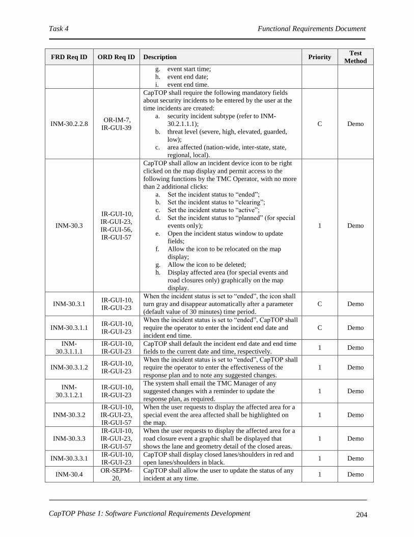
Task 4 Functional Requirements Document
CapTOP Phase 1: Software Functional Requirements Development 204
FRD Req ID ORD Req ID Description Priority Test
Method
g. event start time;
h. event end date;
i. event end time.
INM-30.2.2.8 OR-IM-7,
IR-GUI-39
CapTOP shall require the following mandatory fields
about security incidents to be entered by the user at the
time incidents are created:
a. security incident subtype (refer to INM-
30.2.1.1.1);
b. threat level (severe, high, elevated, guarded,
low);
c. area affected (nation-wide, inter-state, state,
regional, local).
C Demo
INM-30.3
IR-GUI-10,
IR-GUI-23,
IR-GUI-56,
IR-GUI-57
CapTOP shall allow an incident device icon to be right
clicked on the map display and permit access to the
following functions by the TMC Operator, with no more
than 2 additional clicks:
a. Set the incident status to “ended”;
b. Set the incident status to “clearing”;
c. Set the incident status to “active”;
d. Set the incident status to “planned” (for special
events only);
e. Open the incident status window to update
fields;
f. Allow the icon to be relocated on the map
display;
g. Allow the icon to be deleted;
h. Display affected area (for special events and
road closures only) graphically on the map
display.
1 Demo
INM-30.3.1 IR-GUI-10,
IR-GUI-23
When the incident status is set to “ended”, the icon shall
turn gray and disappear automatically after a parameter
(default value of 30 minutes) time period.
C Demo
INM-30.3.1.1 IR-GUI-10,
IR-GUI-23
When the incident status is set to “ended”, CapTOP shall
require the operator to enter the incident end date and
incident end time.
C Demo
INM-
30.3.1.1.1
IR-GUI-10,
IR-GUI-23
CapTOP shall default the incident end date and end time
fields to the current date and time, respectively. 1 Demo
INM-30.3.1.2 IR-GUI-10,
IR-GUI-23
When the incident status is set to “ended”, CapTOP shall
require the operator to enter the effectiveness of the
response plan and to note any suggested changes.
1 Demo
INM-
30.3.1.2.1
IR-GUI-10,
IR-GUI-23
The system shall email the TMC Manager of any
suggested changes with a reminder to update the
response plan, as required.
1 Demo
INM-30.3.2
IR-GUI-10,
IR-GUI-23,
IR-GUI-57
When the user requests to display the affected area for a
special event the area affected shall be highlighted on
the map.
1 Demo
INM-30.3.3
IR-GUI-10,
IR-GUI-23,
IR-GUI-57
When the user requests to display the affected area for a
road closure event a graphic shall be displayed that
shows the lane and geometry detail of the closed areas.
1 Demo
INM-30.3.3.1 IR-GUI-10,
IR-GUI-23
CapTOP shall display closed lanes/shoulders in red and
open lanes/shoulders in black. 1 Demo
INM-30.4 OR-SEPM-
20,
CapTOP shall allow the user to update the status of any
incident at any time. 1 Demo

Task 4 Functional Requirements Document
CapTOP Phase 1: Software Functional Requirements Development 205
FRD Req ID ORD Req ID Description Priority Test
Method
IR-GUI-56,
IR-GUI-57
INM-30.4.1 OR-SEPM-20
CapTOP shall update the last update date/time field
stored with each incident any time that any field in the
incident record is updated.
1 Demo
INM-30.5 OR-IM-4
CapTOP shall strictly enforce the use of pull-down
menus, radio buttons, or selection boxes when any of the
following fields are entered by the user:
Location Fields
a. Street Address/Block;
b. Road Name;
c. Road Direction;
d. Exit Number;
e. Milepost;
f. Closest Intersection/Interchange;
g. Latitude (decimal degrees);
h. Longitude (decimal degrees);
i. Quadrant;
j. Ward.
Incident Fields
a. incident type (refer to INM-30.2.1.1);
b. incident severity (minor, major, regional,
coastal, nationwide);
c. incident status (refer to INM-30.2.1.10);
d. confirmed (yes/no);
e. source of incident;
f. weather conditions;
g. traffic conditions;
h. agencies notified.
i. agencies involved;
j. incident commander;
k. TMC operators involved
l. traffic accident information:
I. accident subtype (refer to INM-
30.2.1.1.1);
II. list of lanes blocked (refer to INM-
30.2.1.3);
III. type of lanes blocked (refer to INM-
30.2.1.4).
IV. type of vehicles involved;
V. personal injuries;
VI. property damage.
m. weather event information:
I. weather event subtype (refer to INM-
30.2.1.1.1);
II. travel condition (refer to INM-
30.2.1.5);
III. pavement condition (refer to INM-
30.2.1.6);
IV. precipitation type (rain, snow, ice,
sleet, hail);
V. wind condition (gusty, nominal,
1 Demo

Task 4 Functional Requirements Document
CapTOP Phase 1: Software Functional Requirements Development 206
FRD Req ID ORD Req ID Description Priority Test
Method
minimal, none);
VI. area affected (coastal, regional, local).
n. construction/maintenance incident information:
I. construction/maintenance incident
subtype (refer to INM-30.2.1.1.1);
II. list of lanes blocked (refer to INM-
30.2.1.3);
III. type of lanes blocked (refer to INM-
30.2.1.4);
o. road closure event:
I. road closure subtype (refer to INM-
30.2.1.1.1);
II. number of lanes blocked;
III. list of lanes blocked (refer to INM-
30.2.1.3);
IV. type of lanes blocked (refer to INM-
30.2.1.4);
p. special event information:
I. special event subtype (refer to INM-
30.2.1.1.1);
II. event sponsor;
q. electronic device outage:
I. electronic device outage subtype (refer
to INM-30.2.1.1.1);
II. list of lanes blocked (refer to INM-
30.2.1.3);
III. type of lanes blocked (refer to INM-
30.2.1.4);
r. security incident:
I. security incident subtype (refer to
INM-30.2.1.1.1);
II. threat level (severe, high, elevated,
guarded, low);
III. area affected (nation-wide, inter-state,
state, regional, local).
INM-30.5.1 OR-IM-4 CapTOP shall restrict the use of free-form text entry on
the fields identified above. 1 Demo
INM-30.5.2 OR-IM-4
CapTOP shall allow the user to type the 1st 3 characters
in each field and the system will provide a filtered list of
selections for that field that begin with the 1st 3
characters typed by the user.
2 Demo
INM-30.5.3 OR-IM-4
CapTOP shall allow the user to select “Other” and enter
in free form text when a desired entry cannot be found in
the list.
1 Demo

Task 4 Functional Requirements Document
CapTOP Phase 1: Software Functional Requirements Development 207
3.7.3.2 Monitoring Incident Status
FRD Req ID ORD Req ID Description Priority Test
Method
INM-40
OR-IM-35,
IR-GUI-16,
UR-TO-1,
OR-CMM-4
CapTOP shall allow the TMC Operator to retrieve and
display the status of all active (all states except ended,
deleted, cancelled, postponed, planned) incidents.
C Demo
INM-40.1
IR-GUI-16,
OR-IM-35,
UR-TO-21
CapTOP shall allow the TMC Operator to retrieve,
display, filter on, and sort on, any of the following
fields which comprise the incident status window:
a. incident ID;
b. incident type (refer to INM-30.2.1.1);
c. incident subtype (refer to INM-30.2.1.1.1);
d. incident severity;
e. incident status (refer to INM-30.2.1.10);
f. incident location;
g. source of incident;
h. incident reported date;
i. incident reported time;
j. event start date;
k. event start time.
C Demo
INM-40.2 OR-SEPM-5
CapTOP shall provide the TMC Operator with a list of
incidents, using the incident status window (refer to
INM-40.1), that are active or planned to start in the
next 4 hours, when they log into the system.
C Demo
INM-40.3 OR-SEPM-5
CapTOP shall allow the user to select any incident in
the incident status window and view all details
pertaining to that incident.
C Demo
INM-50
SR-SYS-2,
IR-GUI-36,
OR-IM-66,
OR-SEPM-6,
OR-CMM-4
CapTOP shall allow users to simultaneously view
incident status, which is refreshed automatically by the
system based on the refresh interval, using the
following methods:
a. Color coded icons on the map display that
appear/disappear based on incident status
(refer to INM-50.1);
b. Via the Incident Management status window
(refer to INM-40.1).
C Demo
INM-50.1
IR-GUI-28,
UR-TO-21,
IR-GUI-56,
IR-GUI-57
CapTOP shall use the following colors for incident
icon types:
a. orange = active construction/maintenance
event;
b. red = active traffic accident;
c. blue = active special event;
d. black = active road closure;
e. gray = incident whose status is “ended” that
will disappear after 30 minutes;
f. white = active incident of all other types.
Note: active is used to indicate all states except ended,
deleted, cancelled, postponed, planned.
C Demo
INM-50.2 IR-GUI-29
The refresh rate for incident icon status (colors, icons
appearing/disappearing) and for the data in the status
window shall be configurable and based upon the
refresh interval (refer to INM-70).
1 Demo
INM-60 SR-SYS-2, CapTOP shall provide a menu option to search for an C Demo

Task 4 Functional Requirements Document
CapTOP Phase 1: Software Functional Requirements Development 208
FRD Req ID ORD Req ID Description Priority Test
Method
IR-GUI-29,
IR-GUI-31,
IR-GUI-32,
OR-IM-65,
IR-GUI-40
incident by the following methods:
a. incident ID;
b. incident description;
c. incident type (refer to INM-30.2.1.1);
d. incident subtype (refer to INM-30.2.1.1.1);
e. incident severity;
f. incident status (refer to INM-30.2.1.10);
g. incident location;
h. incident reported date;
i. incident reported time;
j. incident end date;
k. incident end time.
l. event start date;
m. event start time;
n. keyword search using all fields.
INM-60.1 IR-GUI-32,
UR-TO-5
CapTOP shall allow the TMC Operator to search for
incidents using a rubber-band style box on the map
display to search an area.
C Demo
INM-60.1.1 UR-TO-5
CapTOP shall allow the TMC Operator to select
incidents, network segments, and ITS devices by
boxing an area on the map display.
1 Demo
INM-60.1.2 UR-TO-6
CapTOP shall allow the TMC Operator to de-select
incidents, network segments, and ITS devices by
boxing an area on the map display.
1 Demo
INM-60.2 IR-GUI-32
The result of each search shall be a list of incidents that
are sorted, by default, by incident reported date,
incident reported time, and then incident status.
1 Demo
INM-60.3 IR-GUI-32
The result of each search shall be a list of incidents
sortable by any of the following:
a. incident ID;
b. incident description;
c. incident type (refer to INM-30.2.1.1);
d. incident subtype (refer to INM-30.2.1.1.1);
e. incident severity;
f. incident status (refer to INM-30.2.1.10);
g. incident location;
h. incident reported date;
i. incident reported time;
j. incident end date;
k. incident end time.
1 Demo
INM-70 OR-IM-4
CapTOP shall provide an interface through the
CapTOP operations database for storing and retrieving
incident data.
C Demo
INM-70.1 OR-DOC-2,
OR-DOC-3
CapTOP shall support a refresh rate interval range
from 0 to 99999 seconds, where zero indicates no
polling.
1 Demo
INM-70.2 IR-GUI-36
CapTOP shall be able to request incident status, obtain
incident data, and refresh status windows through the
interface with the CapTOP operations database.
1 Demo
INM-70.3 IR-GUI-31
CapTOP shall allow the user to obtain summary status
information (refer to INM-40.1 for the list of fields) by
hovering over an incident icon.
1 Demo
INM-80 OR-DWA-13, CapTOP shall be able to store incident status and 1 Demo

Task 4 Functional Requirements Document
CapTOP Phase 1: Software Functional Requirements Development 209
FRD Req ID ORD Req ID Description Priority Test
Method
OR-IM-4 operational data (refer to INM-40) in the CapTOP
operations database.
INM-90 OR-IM-49
CapTOP shall provide the TMC Operator proper
access rights to view contents of incident records
currently active by another TMC operator with a “pass
over” function to ensure pending items are addressed
and critical information is passed on to next shift.
C Demo
3.7.3.3 Incident Detection and Classification
FRD Req ID ORD Req ID Description Priority Test
Method
INM-100
OR-IM-1,
SR-SYS-17,
OR-CIP-3,
OR-EM-8,
OR-MMC-11,
OR-MMC-12
CapTOP shall provide an interface to receive, log, and
display incident alerts from the following external
sources:
a. CHART incident alerts;
b. NOVA OpenTMS incident alerts;
c. MWCOG incident alerts;
d. RITIS electronic incident alerts;
e. DDOT CIPS incident alerts;
f. DDOT Snow Operation alerts;
g. DC UCC alerts;
h. DC Public Safety alerts;
i. NCR Emergency Response alerts;
j. WASA alerts;
k. NAWAS alerts;
l. 911/Netviewer electronic incident alerts
(Netviewer is a product of Intergraph, Inc.);
m. WMATA Metro Rail alerts via XML;
n. Metro Bus alerts via XML;
o. CVISN overweight alerts;
p. Police amber alerts;
q. ROP electronic incident alerts;
r. Public Emergency Notification System
s. DC Streetcar incident alerts;
t. DC Tunnel Operations incident alerts.
a. 2
b. 2
c. 3
d. 1
e. 1
f. 1
g. 1
h. 1
i. 1
j. 3
k. 3
l. 1
m. 2
n. 1
o. 2
p. 1
q. 1
r. 1
s. 2
t. 2
Demo
INM-100.1 OR-IM-2
CapTOP shall be able to receive incident notifications
from external sources and display them on the
CapTOP map display, provided any of the following
location information is provided:
a. GPS longitude/latitude coordinates;
b. A valid physical address;
c. A valid intersection;
d. A valid road name, direction and milepost or
exit number;
1 Demo
INM-100.1.1 OR-IM-2
CapTOP shall be provide conversions for the
following fields from their native values (as received
from the external system) to the CapTOP values:
a. Incident severity;
b. Incident status;
c. Incident type (refer to INM-30.2.1.1);
d. Incident location;
1 Demo
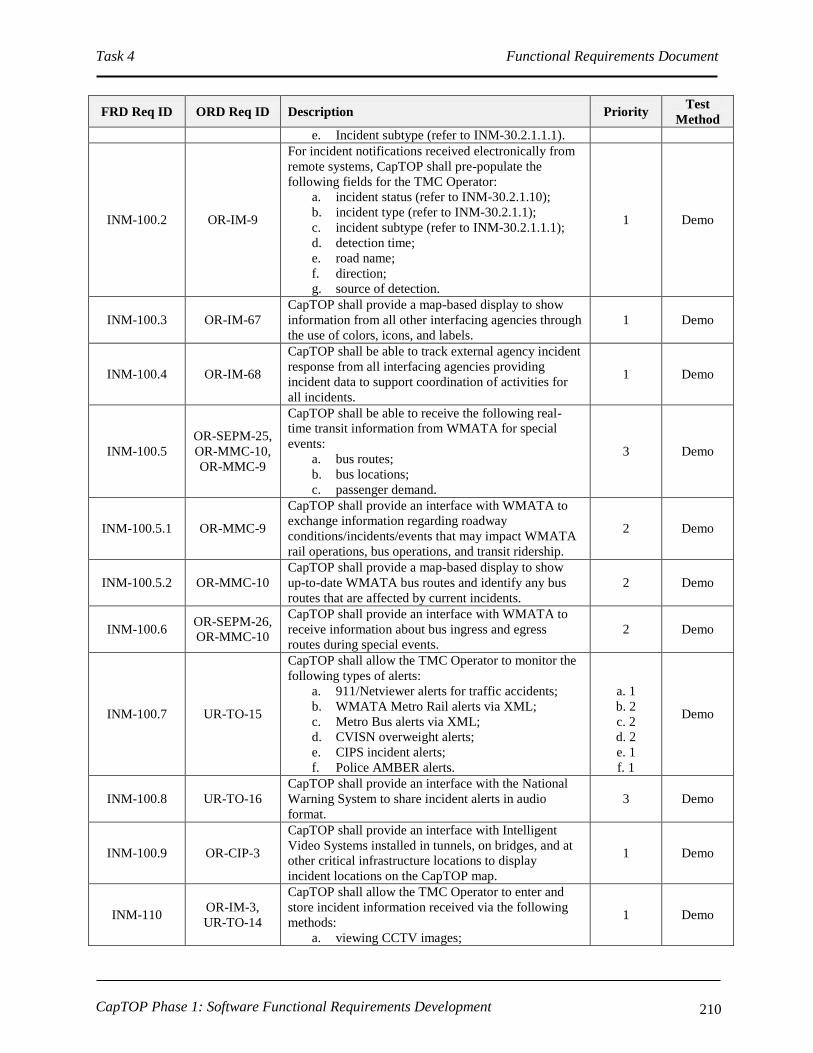
Task 4 Functional Requirements Document
CapTOP Phase 1: Software Functional Requirements Development 210
FRD Req ID ORD Req ID Description Priority Test
Method
e. Incident subtype (refer to INM-30.2.1.1.1).
INM-100.2 OR-IM-9
For incident notifications received electronically from
remote systems, CapTOP shall pre-populate the
following fields for the TMC Operator:
a. incident status (refer to INM-30.2.1.10);
b. incident type (refer to INM-30.2.1.1);
c. incident subtype (refer to INM-30.2.1.1.1);
d. detection time;
e. road name;
f. direction;
g. source of detection.
1 Demo
INM-100.3 OR-IM-67
CapTOP shall provide a map-based display to show
information from all other interfacing agencies through
the use of colors, icons, and labels.
1 Demo
INM-100.4 OR-IM-68
CapTOP shall be able to track external agency incident
response from all interfacing agencies providing
incident data to support coordination of activities for
all incidents.
1 Demo
INM-100.5
OR-SEPM-25,
OR-MMC-10,
OR-MMC-9
CapTOP shall be able to receive the following real-
time transit information from WMATA for special
events:
a. bus routes;
b. bus locations;
c. passenger demand.
3 Demo
INM-100.5.1 OR-MMC-9
CapTOP shall provide an interface with WMATA to
exchange information regarding roadway
conditions/incidents/events that may impact WMATA
rail operations, bus operations, and transit ridership.
2 Demo
INM-100.5.2 OR-MMC-10
CapTOP shall provide a map-based display to show
up-to-date WMATA bus routes and identify any bus
routes that are affected by current incidents.
2 Demo
INM-100.6 OR-SEPM-26,
OR-MMC-10
CapTOP shall provide an interface with WMATA to
receive information about bus ingress and egress
routes during special events.
2 Demo
INM-100.7 UR-TO-15
CapTOP shall allow the TMC Operator to monitor the
following types of alerts:
a. 911/Netviewer alerts for traffic accidents;
b. WMATA Metro Rail alerts via XML;
c. Metro Bus alerts via XML;
d. CVISN overweight alerts;
e. CIPS incident alerts;
f. Police AMBER alerts.
a. 1
b. 2
c. 2
d. 2
e. 1
f. 1
Demo
INM-100.8 UR-TO-16
CapTOP shall provide an interface with the National
Warning System to share incident alerts in audio
format.
3 Demo
INM-100.9 OR-CIP-3
CapTOP shall provide an interface with Intelligent
Video Systems installed in tunnels, on bridges, and at
other critical infrastructure locations to display
incident locations on the CapTOP map.
1 Demo
INM-110 OR-IM-3,
UR-TO-14
CapTOP shall allow the TMC Operator to enter and
store incident information received via the following
methods:
a. viewing CCTV images;
1 Demo

Task 4 Functional Requirements Document
CapTOP Phase 1: Software Functional Requirements Development 211
FRD Req ID ORD Req ID Description Priority Test
Method
b. Citizen phone calls;
c. ROP phone calls;
d. MPD phone calls;
e. police radio.
INM-110.1 OR-IM-11
CapTOP shall allow the TMC operator to enter
incidents from call-in reports involving the following
non-DC agencies:
a. WASA;
b. Verizon;
c. CSX;
d. PEPCO.
3 Demo
INM-110.2 OR-IM-11
CapTOP shall provide an electronic call log for the
TMC Operator to log all phone calls received and
initiated.
3 Demo
INM-110.2.1 OR-IM-11
The call log shall have the following fields:
a. TMC Operator Name;
b. Date;
c. Time;
d. Call Received or Initiated;
e. Person Contacted;
f. Agency Contacted.
3 Demo
INM-120 OR-IM-12
CapTOP shall provide a common data structure for
storing incident information regardless of the source of
the information (refer to INM-30.2.1). C Inspect
INM-130 OR-IM-13
CapTOP shall identify cameras closest to the incident,
where possible, and route video to a default display for
TMC Operator viewing to confirm the incident.
C Demo
INM-130.1 OR-IM-13 CapTOP shall automatically direct the camera to a
preset that is in the direction of the incident. C Demo
INM-130.2 OR-IM-14,
UR-TO-14
CapTOP shall provide the TMC Operators with CCTV
camera controls to pan/tilt/zoom/focus cameras to
verify the incident, assess the nature of the incident,
and provide support in managing the incident.
C Demo
INM-130.3 OR-IM-14,
UR-TO-14
CapTOP shall accept the incident into the incident
database only after confirmation that a camera close to
the incident has been viewed, if one or more cameras
are close to the incident location.
C Demo
INM-140 OR-IM-15
CapTOP shall be able to classify incidents based on
the incident location, incident type, incident subtype,
and incident severity.
C Demo
INM-140.1 OR-IM-15
CapTOP shall prompt the user to verify that he has
accurately entered the location, incident type, incident
subtype, and incident severity that is used to classify
the incident.
1 Demo
INM-140.2 OR-IM-15
CapTOP shall accurately retrieve the appropriate
incident response plan (or plans) based on the
operator’s classification (location, incident type,
incident subtype, incident severity).
1 Demo
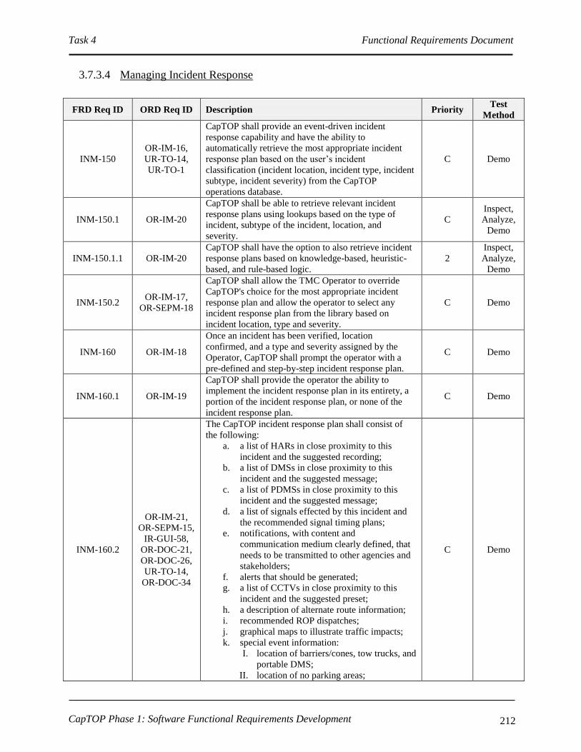
Task 4 Functional Requirements Document
CapTOP Phase 1: Software Functional Requirements Development 212
3.7.3.4 Managing Incident Response
FRD Req ID ORD Req ID Description Priority Test
Method
INM-150
OR-IM-16,
UR-TO-14,
UR-TO-1
CapTOP shall provide an event-driven incident
response capability and have the ability to
automatically retrieve the most appropriate incident
response plan based on the user’s incident
classification (incident location, incident type, incident
subtype, incident severity) from the CapTOP
operations database.
C Demo
INM-150.1 OR-IM-20
CapTOP shall be able to retrieve relevant incident
response plans using lookups based on the type of
incident, subtype of the incident, location, and
severity.
C
Inspect,
Analyze,
Demo
INM-150.1.1 OR-IM-20
CapTOP shall have the option to also retrieve incident
response plans based on knowledge-based, heuristic-
based, and rule-based logic.
2
Inspect,
Analyze,
Demo
INM-150.2 OR-IM-17,
OR-SEPM-18
CapTOP shall allow the TMC Operator to override
CapTOP's choice for the most appropriate incident
response plan and allow the operator to select any
incident response plan from the library based on
incident location, type and severity.
C Demo
INM-160 OR-IM-18
Once an incident has been verified, location
confirmed, and a type and severity assigned by the
Operator, CapTOP shall prompt the operator with a
pre-defined and step-by-step incident response plan.
C Demo
INM-160.1 OR-IM-19
CapTOP shall provide the operator the ability to
implement the incident response plan in its entirety, a
portion of the incident response plan, or none of the
incident response plan.
C Demo
INM-160.2
OR-IM-21,
OR-SEPM-15,
IR-GUI-58,
OR-DOC-21,
OR-DOC-26,
UR-TO-14,
OR-DOC-34
The CapTOP incident response plan shall consist of
the following:
a. a list of HARs in close proximity to this
incident and the suggested recording;
b. a list of DMSs in close proximity to this
incident and the suggested message;
c. a list of PDMSs in close proximity to this
incident and the suggested message;
d. a list of signals effected by this incident and
the recommended signal timing plans;
e. notifications, with content and
communication medium clearly defined, that
needs to be transmitted to other agencies and
stakeholders;
f. alerts that should be generated;
g. a list of CCTVs in close proximity to this
incident and the suggested preset;
h. a description of alternate route information;
i. recommended ROP dispatches;
j. graphical maps to illustrate traffic impacts;
k. special event information:
I. location of barriers/cones, tow trucks, and
portable DMS;
II. location of no parking areas;
C Demo

Task 4 Functional Requirements Document
CapTOP Phase 1: Software Functional Requirements Development 213
FRD Req ID ORD Req ID Description Priority Test
Method
III. location of traffic control officers;
IV. location of command vehicles and other
special use vehicles;
V. parking information;
VI. recommended transit usage;
l. hyperlinks to checklists, guidelines and
procedural documents.
INM-160.2.1 OR-IM-21,
OR-SEPM-13
The CapTOP incident response plan shall provide an
option that flashes the ITS device icons (CCTV, DMS,
HAR, Signals) on the map display that are to be
utilized as part of the incident response plan.
1 Demo
INM-160.2.1.1 OR-SEPM-22
CapTOP shall provide the TMC Operator a map-based
display to identify the following devices that must be
checked frequently during incidents:
a. traffic signals;
b. CCTV cameras;
c. DMS;
d. PDMS;
e. HAR.
2 Demo
INM-160.2.2 OR-SEPM-2
CapTOP shall display the following special event
information on the map display:
a. road closures;
b. routes impacted by the special event;
c. parking restrictions;
d. ITS device/signals used for the special events.
C Demo
INM-160.2.3 OR-DOC-8
CapTOP shall maintain a library of pre-defined lists of
devices required to support incident management that
will be used by the TMC Manager in defining incident
response plans.
C Demo
INM-160.2.4 OR-SEPM-10
CapTOP shall disseminate traffic information during
incidents to the public using the following methods:
a. HAR;
b. DMS;
c. PDMS;
d. Web.
1 Demo
INM-160.2.5 OR-SEPM-27
CapTOP shall be able to disseminate the following
real-time transit information at special event locations
using HAR, DMS, and PDMS:
a. bus routes;
b. bus locations based on reported positions.
2 Demo
INM-160.2.6 OR-SEPM-28
CapTOP shall be able to retrieve and display up-to-
date information about the location, communication
status, and current message of PDMSs and DMSs
operated by NOVA's OpenTMS and SHA's CHART
systems that provide information for drivers destined
for the city.
1 Demo
INM-160.2.7 UR-TO-22
CapTOP shall provide the TMC Manager the ability to
share incident information with other agencies and
jurisdictions.
1 Demo
INM-160.2.8 IR-GUI-36,
IR-GUI-58
The CapTOP incident response plan shall provide an
option that displays alternate route information on the
map display that are to be utilized as part of the
incident response plan.
2 Demo

Task 4 Functional Requirements Document
CapTOP Phase 1: Software Functional Requirements Development 214
FRD Req ID ORD Req ID Description Priority Test
Method
INM-160.3 OR-IM-16
CapTOP shall be able to provide a .pdf link from the
incident response plan to a procedural guidelines
document for Scene Management that includes the
following:
a. Procedures for reporting incidents;
b. Procedures for moving vehicles;
c. Procedures for emergency traffic control;
d. Procedures for use of emergency flashers;
e. Parking and staging;
f. Procedures for response teams;
g. Procedures for use of response equipment.
1 Demo
INM-160.4 OR-IM-45
CapTOP shall incorporate SOP checklists in incident
response plans and provide the TMC Operator
electronic checklists that step through a prioritized list
of needed actions as part of the incident response.
C Demo
INM-160.4.1 OR-IM-22
CapTOP shall provide check boxes and comments to
ensure each step is implemented, or alternatively to
document why it was skipped.
1 Demo
INM-170
OR-IM-23,
OR-IM-34,
OR-TID-1
CapTOP shall provide a separate data structure for
storing incident information that will be released
outside of DDOT.
1 Demo
INM-170.1
OR-IM-23,
OR-IM-34,
OR-TID-1
CapTOP shall require the TMC Operator to filter
incident data applicable for general public
consumption and store in a separate data structure
available for use for incident notifications, web
dissemination, and other mechanisms used to
disseminate information to the public.
1 Demo
INM-180
OR-IM-24,
UR-TO-14,
OR-DOC-34
CapTOP shall allow message notifications to be sent to
PCs, cell phones, Blackberries, and PDAs. 1 Demo
INM-180.1
OR-IM-53,
OR-TID-1,
OR-CMM-6
CapTOP shall be able to disseminate the following
details about incidents via notifications to specific
groups using distribution lists, appropriate for each
incident type and subtype:
a. location;
b. type of event;
c. status of event;
d. estimated duration of event (calculated from
event start date/time and event end date/time);
e. start time;
f. end time.
1 Demo
INM-180.1.1 OR-IM-25
CapTOP shall allow the TMC Operator to disseminate
notifications to the public, which contain the details,
but without sensitive personal information, of each
incident.
1 Demo
INM-180.1.2 OR-CMM-6
CapTOP shall disseminate the following work zone
information to the public via the Internet:
a. planned maintenance - road, lanes, start/end
date and times;
b. planned construction- road, lanes, start/end
date and times;
c. unplanned maintenance- road, lanes, start/end
date and times;
2 Demo

Task 4 Functional Requirements Document
CapTOP Phase 1: Software Functional Requirements Development 215
FRD Req ID ORD Req ID Description Priority Test
Method
d. unplanned construction- road, lanes, start/end
date and times.
INM-180.2 OR-IM-26
CapTOP shall provide the TMC Operator the ability to
disseminate incident information to the media and the
press.
1 Demo
INM-180.3 OR-IM-27
CapTOP shall be able to generate and send incident
notifications to multiple agencies and individuals via
the following formats:
a. instant messages;
b. email messages (to computers, PDAs, and
Blackberry-type devices);
c. phone voicemail;
d. web alerts.
1 Demo
INM-180.4 OR-IM-28,
OR-IM-51
CapTOP shall be able to send incident notifications to
various stakeholders based on location, road type, time
of day, severity, and type.
1 Demo
INM-180.5 OR-IM-29,
OR-TID-1
CapTOP shall maintain "notification" distribution
list(s) of stakeholders for each type/subtype of
incident.
1 Demo
INM-180.6 OR-IM-29,
OR-TID-1
CapTOP shall send electronic notifications during
incidents when there is a change in incident status. 1 Demo
INM-180.6.1 OR-IM-30
CapTOP shall be able to send notifications to
individuals and distribution lists via the Alert DC
System.
1 Demo
INM-180.7 OR-IM-33
CapTOP shall be able to confirm receipt of outgoing
alerts and notifications sent electronically to specific
distribution lists.
1 Demo
INM-180.8
OR-IM-23,
OR-IM-34,
OR-TID-1
CapTOP shall provide online templates for creating
and storing text message notifications for different
types of incidents for dissemination to subscribers
(subscriber = any user with an email or SMS address).
1 Demo
INM-180.9 OR-IM-23,
OR-IM-34
CapTOP shall provide online templates for creating
and storing text message alerts for different types of
incidents for dissemination to CapTOP users logged
into the system.
1 Demo
INM-190
OR-IM-40,
OR-IM-41,
OR-SEPM-1,
OR-DOC-29,
OR-CMM-3
CapTOP shall provide the TMC Operator and TMC
Manager with alerts/reminders to take action on
DDOT incidents (not external incidents) at the
following times:
a. start of incident;
b. expected duration of incident exceeded;
c. after a pre-configured amount of time has
expired if no updates have occurred to active
(all states except ended, deleted, cancelled,
postponed, planned) incidents;
d. for road closures at the scheduled tear-down
time.
C Demo
INM-190.1 OR-SEPM-20
CapTOP shall provide reminders to TMC Operators
and TMC Managers for active (all states except ended,
deleted, cancelled, postponed, planned) traffic
accidents and electronic device outages (traffic signal
outage and power) that have had no activity for X
minutes, where X is variable based on incident
C Demo
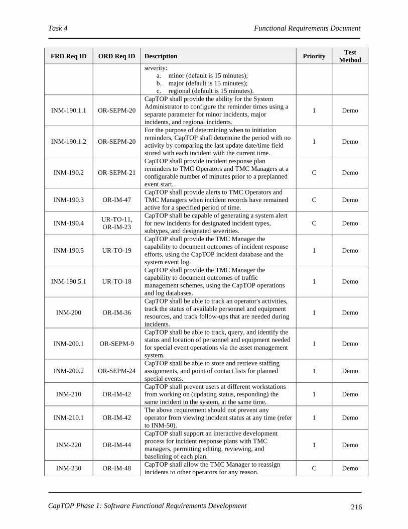
Task 4 Functional Requirements Document
CapTOP Phase 1: Software Functional Requirements Development 216
FRD Req ID ORD Req ID Description Priority Test
Method
severity:
a. minor (default is 15 minutes);
b. major (default is 15 minutes);
c. regional (default is 15 minutes).
INM-190.1.1 OR-SEPM-20
CapTOP shall provide the ability for the System
Administrator to configure the reminder times using a
separate parameter for minor incidents, major
incidents, and regional incidents.
1 Demo
INM-190.1.2 OR-SEPM-20
For the purpose of determining when to initiation
reminders, CapTOP shall determine the period with no
activity by comparing the last update date/time field
stored with each incident with the current time.
1 Demo
INM-190.2 OR-SEPM-21
CapTOP shall provide incident response plan
reminders to TMC Operators and TMC Managers at a
configurable number of minutes prior to a preplanned
event start.
C Demo
INM-190.3 OR-IM-47
CapTOP shall provide alerts to TMC Operators and
TMC Managers when incident records have remained
active for a specified period of time.
C Demo
INM-190.4 UR-TO-11,
OR-IM-23
CapTOP shall be capable of generating a system alert
for new incidents for designated incident types,
subtypes, and designated severities.
C Demo
INM-190.5 UR-TO-19
CapTOP shall provide the TMC Manager the
capability to document outcomes of incident response
efforts, using the CapTOP incident database and the
system event log.
1 Demo
INM-190.5.1 UR-TO-18
CapTOP shall provide the TMC Manager the
capability to document outcomes of traffic
management schemes, using the CapTOP operations
and log databases.
1 Demo
INM-200 OR-IM-36
CapTOP shall be able to track an operator's activities,
track the status of available personnel and equipment
resources, and track follow-ups that are needed during
incidents.
1 Demo
INM-200.1 OR-SEPM-9
CapTOP shall be able to track, query, and identify the
status and location of personnel and equipment needed
for special event operations via the asset management
system.
1 Demo
INM-200.2 OR-SEPM-24
CapTOP shall be able to store and retrieve staffing
assignments, and point of contact lists for planned
special events.
1 Demo
INM-210 OR-IM-42
CapTOP shall prevent users at different workstations
from working on (updating status, responding) the
same incident in the system, at the same time.
1 Demo
INM-210.1 OR-IM-42
The above requirement should not prevent any
operator from viewing incident status at any time (refer
to INM-50).
1 Demo
INM-220 OR-IM-44
CapTOP shall support an interactive development
process for incident response plans with TMC
managers, permitting editing, reviewing, and
baselining of each plan.
1 Demo
INM-230 OR-IM-48 CapTOP shall allow the TMC Manager to reassign
incidents to other operators for any reason. C Demo

Task 4 Functional Requirements Document
CapTOP Phase 1: Software Functional Requirements Development 217
FRD Req ID ORD Req ID Description Priority Test
Method
INM-230.1 OR-IM-48
CapTOP shall prompt the TMC Operator to reassign
current active (all incidents except ended, deleted,
cancelled, postponed, planned) incidents assigned to
him/her during logout.
C Demo
INM-230.1.1 OR-IM-48 The reassigning user shall be prompted with only a list
of users currently logged in. 1 Demo
INM-230.1.2 OR-IM-48
The newly assigned user shall be required to accept
confirmation of the reassignment incident prior to the
primary user be permitted to logout.
C Demo
INM-230.1.2.1 OR-IM-48 The reassigned incident shall be logged on the TMC
Manager’s workstation using a pop-up alert. 1 Demo
INM-240 OR-IM-50
CapTOP shall provide the TMC Operator access to the
following resources:
a. contact lists;
b. incident response plans;
c. SOPs;
d. help functions.
C Demo
INM-250 OR-IM-51
CapTOP shall maintain a stakeholder contact list in the
operations database that can identify Points of Contact
(POCs) for all agencies/organizations involved in
traffic incident management and response.
C Demo
INM-250.1 OR-IM-52
CapTOP shall be able retrieve and display a list of
contacts that need to be informed of incidents at
certain locations and of certain types.
C Demo
INM-260 OR-SEPM-16
CapTOP shall maintain a comprehensive Point of
Contact (POC) list for each special event that identifies
the organizers, contacts at event venue, and individuals
in various DC agencies.
C Demo
INM-260.1 OR-SEPM-17
The CapTOP Special Event POC list shall consist of
the following fields:
a. the name of each POC;
b. POC agency;
c. POC title;
d. POC address;
e. POC e-mail address;
f. POC phone number;
g. POC cell phone number.
C Demo
INM-270 OR-IM-55 CapTOP shall be able to identify and prompt the
Operator for the removal of duplicate incident records. 1 Demo
INM-270.1 OR-IM-55
CapTOP shall be able to identify duplicate incident
records, if a new incident of the same type is created
within X feet of the primary incident location, where X
defaults to 100 feet, and where X is configurable by
the System Administrator.
1 Demo
INM-280 OR-IM-56,
OR-DOC-29
CapTOP shall be able to prompt the Operator to reset
ITS devices to their pre-incident status when closing
an incident.
1 Demo
INM-280.1 OR-IM-57,
OR-SEPM-15
CapTOP shall, upon operator confirmation, implement
the following device reset actions:
a. blanking a DMS;
b. restoring a default message to a DMS;
c. blanking a PDMS;
d. restoring a default message to a PDMS;
1 Demo

Task 4 Functional Requirements Document
CapTOP Phase 1: Software Functional Requirements Development 218
FRD Req ID ORD Req ID Description Priority Test
Method
e. blanking a HAR;
f. restoring a default message to a HAR;
g. returning cameras to their default
position/preset.
INM-290 OR-IM-69
CapTOP shall provide a map-based display to show
the schedule and status of reversible lanes for
monitoring and control purposes during incidents.
C Demo
INM-300 OR-IM-70
CapTOP shall support Police Amber alerts by
permitting Amber alert messages to be displayed on
the following:
a. DMS;
b. PDMS.
1 Demo
INM-310 OR-IM-71
CapTOP shall support Police Amber alerts by
permitting Amber alert messages to be recorded on
HAR devices.
1 Demo
3.7.3.5 Incident Management Scheduler
FRD Req ID ORD Req ID Description Priority Test
Method
INM-320
OR-SEPM-1,
OR-DOC-30,
OR-DOC-29
CapTOP shall be able to define and schedule the
following event types using a schedule editor:
a. Weather event;
b. Construction event;
c. Emergency Road closure event;
d. Special event;
e. Maintenance repair event;
f. Other.
C Demo
INM-320.1 OR-DOC-22,
OR-DOC-30
The CapTOP schedule capability shall permit time of
day recurring and non-recurring entries for designated
event types.
C Demo
INM-320.2 OR-DOC-22,
OR-DOC-30
The schedule shall permit a non-recurring, one-time
only event to be scheduled, where the user specifies a
schedule name, event name, reminder date/time, event
start date, event start time, event end date, and event
end time.
C Demo
INM-320.3 OR-DOC-22,
OR-DOC-30
CapTOP shall provide a recurring schedule capability
and permit any of the following recurring entry types:
a. Weekdays – Monday through Friday;
b. Weekends – Saturday and Sunday only;
c. All Days – Monday through Sunday;
d. One day or any combination of days per
week;
e. One day or any combination of days per
month.
C Demo
INM-320.3.1 OR-DOC-22,
OR-DOC-30
CapTOP shall allow recurring schedule entries to be
created for designated events, where the user specifies
a schedule name, event name, recurring entry type,
reminder date/time, event start date, event start time,
event end date, and event end time (event end
date/time optional).
C Demo

Task 4 Functional Requirements Document
CapTOP Phase 1: Software Functional Requirements Development 219
FRD Req ID ORD Req ID Description Priority Test
Method
INM-320.3.2 OR-DOC-22,
OR-DOC-30
CapTOP shall permit an optional event end date to be
specified for all recurring schedule entries. 1 Demo
INM-320.3.2.1 OR-DOC-22,
OR-DOC-30
CapTOP shall implement the recurring scheduling
indefinitely if no event end date is specified. 1 Demo
INM-320.3.3 OR-DOC-22,
OR-DOC-30
CapTOP shall allow a Holiday schedule to be specified
for the CapTOP system. 1 Demo
INM-320.3.3.1 OR-DOC-22,
OR-DOC-30
CapTOP shall allow the user to indicate whether each
Holiday is treated as an exception to the recurring
schedule.
1 Demo
INM-320.3.3.2 OR-DOC-22,
OR-DOC-30
CapTOP shall allow the user to specify each Holiday
exception to be treated as either a Weekend or
Weekday whenever encountered.
1 Demo
INM-330 OR-DOC-22,
OR-DOC-30
CapTOP shall allow the TMC Operator to edit and
delete scheduled entries. 1 Demo
3.7.3.6 Incident Management Reports
FRD Req ID ORD Req ID Description Priority Test
Method
INM-340
OR-DOC-22,
OR-DOC-30,
IR-GUI-57
CapTOP shall allow the TMC Operator to produce a
report of all scheduled entries for any of the following:
a. individual special event;
b. individual road closure events;
c. individual electronic device outage event;
d. individual construction/maintenance event;
e. all special events;
f. all road closures;
g. all electronic device outages;
h. all construction/maintenance events.
C Demo
INM-340.1 OR-DOC-22,
OR-DOC-30
The report shall list all schedule entries, and shall
contain the following:
a. schedule name;
b. event name;
c. recurrent entry type (optional);
d. event start date;
e. event start time;
f. event end date (optional);
g. event end time (optional);
h. incident type (refer to INM-30.2.1.1);
i. incident subtype (refer to INM-30.2.1.1.1);
j. incident severity;
k. incident status (refer to INM-30.2.1.10);
l. incident location;
m. source of incident.
C Demo
INM-350
SR-SYS-22,
SR-SYS-36,
IR-GUI-8
CapTOP shall be able to generate real-time tabular
reports that show the status of all incidents at the TMC
Operator’s request.
C Demo
INM-350.1
SR-SYS-22,
SR-SYS-36,
IR-GUI-8,
OR-IM-46,
CapTOP shall query, retrieve, display, and be able to
filter on, and sort on any the following information in
the incident status report:
a. incident ID;
2 Demo

Task 4 Functional Requirements Document
CapTOP Phase 1: Software Functional Requirements Development 220
FRD Req ID ORD Req ID Description Priority Test
Method
OR-IM-58 b. incident type (refer to INM-30.2.1.1);
c. incident subtype (refer to INM-30.2.1.1.1);
d. incident severity;
e. incident status (refer to INM-30.2.1.10);
f. incident location;
g. source of incident;
h. incident reported date;
i. incident reported time;
j. incident end date;
k. incident end time;
l. event start date;
m. event start time;
n. event end date;
o. event end time.
INM-350.2 OR-TDCA-19
CapTOP shall collect and format traffic and incident
data for direct use in DDOT's current traffic
simulation/analysis application (currently Synchro).
2 Demo
INM-360
OR-PM-3,
OR-PM-4,
OR-SEPM-14,
SR-SYS-22,
UR-TO-20
CapTOP shall be able to create performance reports
related to incident management. 2 Demo
INM-360.1
OR-PM-4,
OR-SEPM-14,
SR-SYS-22,
UR-TO-20
CapTOP shall be able to create a separate performance
report for any incident with the following incident
information, using data in the CapTOP operations, log,
and archived databases:
a. incident ID;
b. incident type;
c. incident subtype;
d. incident location;
e. incident severity;
f. timeline of all system activities related to an
incident;
g. messages to DMS/PDMS;
h. messages to HAR;
i. call logs;
j. operator notes;
k. incident response times;
l. incident durations based on type;
m. changes to incident status;
n. alerts and notifications sent to other systems.
o. alerts and notifications received by other
systems.
p. special event information:
I. number of attendees;
II. event duration;
III. traffic impacts;
2 Demo
INM-360.1.1
OR-PM-4,
OR-SEPM-14,
SR-SYS-22,
UR-TO-20
CapTOP shall provide graphical displays to show a
visual timeline of the evolution of the incident through
various incident states (from beginning to end).
2 Demo
INM-360.2
OR-DWA-4,
OR-SEPM-3,
OR-SEPM-8
CapTOP shall be able to produce the following
performance reports, useful for FHWA incident
management performance reporting and system
2 Demo

Task 4 Functional Requirements Document
CapTOP Phase 1: Software Functional Requirements Development 221
FRD Req ID ORD Req ID Description Priority Test
Method
performance evaluation, based on operations and
archived data:
a. number of incidents over a specified time
period;
b. number of incidents of a certain type/subtype
over a specified time period;
c. list of incidents of a certain type/subtype over
a specified time period;
d. number of device malfunctions over a
specified time period;
e. average duration of all incidents over a
specified time period;
f. average duration of incidents of a certain
type/subtype over a specified time period;
g. average number of ROPs for all incidents
over a specified time period;
h. average number of ROPS for incidents of a
certain type/subtype over a specified time
period;
i. average elapsed time from incident reported
time to incident confirmation;
j. average elapsed time from incident
occurrence to incident response;
k. number of ROP assists over a specified time
period;
l. average number of DMS used for all incidents
over a specified time period;
m. average number of DMS used for incidents of
a certain type/subtype over a specified time
period;
n. average number of PDMS used for all
incidents over a specified time period;
o. average number of PDMS used for incidents
of a certain type/subtype over a specified time
period;
p. number of ROPs required per incident;
q. number of ROPS required per special event;
r. number of DMS required per incident;
s. number of DMS required per special event;
t. number of PDMS required per incident;
u. number of PDMS required per special event;
v. number of times different agencies responded
to incidents;
w. type and average quantity of field equipment
used for all incidents over a specified time
period;
x. type and average quantity of field equipment
used for incidents of a certain type/subtype
over a specified time period;
y. average number of DDOT field technicians
used for all incidents over a specified time
period;
z. average number of DDOT field technicians
used for incidents of a certain type/subtype

Task 4 Functional Requirements Document
CapTOP Phase 1: Software Functional Requirements Development 222
FRD Req ID ORD Req ID Description Priority Test
Method
over a specified time period;
aa. average number of DDOT staff hours used for
all incidents over a specified time period;
bb. average number of DDOT staff hours used for
incidents of a certain type/subtype over a
specified time period;
cc. average number of attendees at special events
over a specified time period;
dd. average number of attendees at a special event
subtype over a specified time period;
ee. average number of transit riders at special
events over a specified time period;
ff. average number of cones used for traffic
management for all incidents over a specified
time period;
gg. average number of cones used for traffic
management incidents of a certain
type/subtype;
hh. number of DDOT field technicians used for
each incident;
ii. number of DDOT field technicians used for
each special event;
jj. number of DDOT staff hours used for each
incident;
kk. number of DDOT staff hours used for each
special event;
ll. number of attendees at each special event ;
mm. number of transit riders at each
special event (if available, estimate only);
nn. number of cones used for traffic management
at each special event.
INM-360.3 OR-ROP-4,
OR-ROP-5
CapTOP shall provide ROP performance reports to
that report the following over a user-specified time
interval:
a. status/availability of ROP vehicles;
b. number of drivers per shift;
c. resources consumed;
d. expenditures;
e. number of ROP unit assists.
2 Demo
INM-370 OR-PM-5 CapTOP shall produce post-event reports that
document the resources used. 2 Demo
INM-370.1 OR-SEPM-3
CapTOP shall provide DDOT staff with functions to
track personnel activities associated with supporting
special events.
1 Demo
INM-370.1.1 OR-SEPM-3 The information shall be able to be viewed on the
workstation and printed in the form of a report. 2 Demo
INM-370.2 OR-SEPM-3
CapTOP shall provide DDOT staff with functions to
view data and generate reports related to personnel
activities and costs associated with supporting special
events.
2 Demo
INM-380
SR-SYS-22,
SR-SYS-36,
IR-GUI-8,
CapTOP shall be able to display and print the
following reports:
a. For a user specified incident, provide a
2 Demo

Task 4 Functional Requirements Document
CapTOP Phase 1: Software Functional Requirements Development 223
FRD Req ID ORD Req ID Description Priority Test
Method
SR-SYS-25 detailed report of all information in the
database pertaining to that incident (refer to
INM-30.2.1).
b. For a user specified time-interval, provide a
list of all incidents with the following fields:
I. incident ID;
II. incident type (refer to INM-30.2.1.1);
III. incident subtype (refer to INM-
30.2.1.1.1);
IV. incident severity;
V. incident status (refer to INM-
30.2.1.10);
VI. incident location;
VII. incident reported date;
VIII. incident reported time;
IX. incident end date;
X. incident end time;
XI. event start date;
XII. event start time;
XIII. event end date;
XIV. event end time.
c. An ad-hoc report where the user can query
any data stored in incident related databases;
d. For a user specified time-interval and for a
given User ID, provide a list of all incidents
with the following fields:
I. incident ID;
II. incident type (refer to INM-30.2.1.1);
III. incident subtype (refer to INM-
30.2.1.1.1);
IV. incident severity;
V. incident status (refer to INM-
30.2.1.10);
VI. incident location;
VII. incident reported date;
VIII. incident reported time;
IX. incident end date;
X. incident end time;
XI. event start date;
XII. event start time;
XIII. event end date;
XIV. event end time.
e. For a user specified time-interval, provide a
work-zone report that shows the road name,
direction, closure information, and date and
time last updated.
INM-390 OR-IM-37,
UR-TO-14
CapTOP shall be able to process and organize incident
data to provide comprehensive reports that address the
following incident management phases:
a. detection;
b. verification;
c. response;
d. after-the-fact analysis of incident
management activities.
2 Demo

Task 4 Functional Requirements Document
CapTOP Phase 1: Software Functional Requirements Development 224
FRD Req ID ORD Req ID Description Priority Test
Method
INM-390.1 OR-DOC-9,
SR-SYS-27
CapTOP shall provide a report capability to retrieve all
operator actions/commands from the log that are part
of an incident response.
2 Demo
INM-390.2 IR-GUI-8
CapTOP shall provide tabular reports for the
following:
a. Current active (all states except ended,
deleted, cancelled, postponed, planned)
incidents, selectable by type/subtype, sortable
by location, incident reported date, and
incident reported time;
b. Historical incidents, selectable by
type/subtype, sortable by location, incident
reported date, and incident reported time.
Note: if type is special event, road closure event,
construction/maintenance event, or electronic device
outage event, in lieu of incident reported date/time, use
event date date/time.
2 Demo
INM-400 OR-IM-38
CapTOP shall provide the TMC operator the ability to
generate incident reports and activity reports
describing the characteristics and status of all incidents
addressed during each operations shift.
2 Demo
INM-410 OR-IM-39
CapTOP shall be able to generate incident reports, by
type, tailored to the needs of the following
stakeholders:
a. elected officials;
b. supervisors;
c. senior management.
2 Analyze
INM-420
SR-SYS-22,
SR-SYS-36,
IR-GUI-8
CapTOP shall support the following capabilities for all
reports:
a. be able to display all reports in a tabular
format;
b. be able to display graphical reports in a
Microsoft Excel-like 2-dimensional or 3-
dimensional format.
c. be able to print all reports in landscape or
portrait modes;
d. include the report name and date generated on
the header;
e. support a template capability for each report,
allowing the user to select which fields to
display;
f. include the page number on the footer.
a. 2
b. 2
c. 2
d. 2
e. 2
f. 2
Demo
3.7.3.7 Incident Management Logging Requirements
FRD Req ID ORD Req ID Description Priority Test
Method
INM-430 UR-TO-11,
OR-TOM-1
CapTOP shall store and time stamp all operator and
system activities that pertain to incidents and provide
the output in a time sequential log.
C Demo
INM-430.1 UR-TO-11, CapTOP shall have the capability to automatically log C Demo

Task 4 Functional Requirements Document
CapTOP Phase 1: Software Functional Requirements Development 225
FRD Req ID ORD Req ID Description Priority Test
Method
OR-C2F-3,
OR-C2F-4,
OR-DWA-13,
SR-SYS-27
the following user activities to the log database that
pertain to incidents:
a. any operator-initiated action resulting in a
request to access information;
b. any operator-initiated action that attempts to,
or results in, a change to an incident;
c. user actions that are part of incident response;
d. operator login;
e. operator logout.
(Note: also refer to the LOG-* requirements).
INM-430.1.1
OR-IM-59,
OR-SEPM-7,
SR-SYS-27,
UR-TO-11
CapTOP shall provide the ability to log the following
information needed to support a comprehensive log of
activities for each event/incident in the system:
a. commands entered by the TMC Operator,
including operator name, date, and time;
b. command description;
c. phone calls made;
d. incident detection source;
e. incident updates – to any fields;
f. confirmation time;
g. clearance time;
h. resources used/dispatched;
i. other agencies notified;
j. control actions to DMS;
k. control actions to PDMS;
l. control actions to HAR;
m. control actions to Traffic Signals;
n. incident response plan actions;
o. any messages/notifications received or sent to
external organizations.
C Demo
INM-430.1.2 OR-IM-31,
SR-SYS-27
CapTOP shall log all TMC Operator transmitted
notifications and alerts. C Demo
INM-430.1.2.1 OR-IM-32
The CapTOP log shall identify the date, time, operator
who generated the alert or notification, and message
content.
C Demo
INM-430.2 UR-TO-11
CapTOP shall have the capability to automatically log
the following system activities to the log database that
pertain to incidents:
a. any system-initiated action that attempts to, or
results in, a change to an incident;
b. software application login;
c. software application logout;
d. software application errors;
e. database login;
f. database logout.
(Note: also refer to the LOG-* requirements).
C Demo
INM-430.3 UR-TO-11 CapTOP shall provide a window to display all logged
system and user activities for incidents. 1 Demo
INM-430.4 UR-TO-11
CapTOP shall assign and store one of the following
action types when logging all Incident Management
activities:
a. operator input;
b. operator incident response;
1 Demo

Task 4 Functional Requirements Document
CapTOP Phase 1: Software Functional Requirements Development 226
FRD Req ID ORD Req ID Description Priority Test
Method
c. operator informational message;
d. operator error;
e. system warning;
f. system error;
g. system information message;
h. software application warning;
i. software application error;
j. software application information message.
INM-430.5 UR-TO-11
For log entries triggered by user actions, CapTOP shall
log the following:
a. Username;
b. Date stamp;
c. Time stamp;
d. Workstation ID;
e. Workstation IP address;
f. Action type;
g. Description of action (include the incident ID,
description of action, and summary incident
status).
1 Demo
INM-430.6 UR-TO-11
For log entries generated by the CapTOP applications,
CapTOP shall log the following:
a. Application name;
b. Date stamp;
c. Time stamp;
d. Action type;
e. Description of action.
1 Demo
INM-430.7 OR-IM-60 CapTOP shall make all log entries read-only,
changeable by only the System Administrator. C Demo
INM-440 OR-DWA-5,
SR-SYS-27
CapTOP shall have the capability to query and retrieve
all operator actions/commands that pertain to incidents
from the log by filtering on the following:
a. Workstation ID;
b. Workstation IP address;
c. Username;
d. Date stamp;
e. Time stamp;
f. Action type.
1 Demo
3.7.3.8 Incident Management Archiving Requirements
FRD Req ID ORD Req ID Description Priority Test
Method
INM-450 OR-IM-43,
OR-SEPM-4
CapTOP shall archive all incident data to develop,
evaluate, and refine strategies, and scenarios for
different types of events/incidents under different
conditions.
1 Demo
INM-460 OR-IM-43,
OR-SEPM-4
CapTOP or related third party tools shall have the
capability to format and perform automated and
manually initiated migration of logged data that
pertains to incidents from the log database to the
archived database.
1 Demo
INM-470 OR-IM-43, CapTOP or related third party tools shall have the 1 Demo

Task 4 Functional Requirements Document
CapTOP Phase 1: Software Functional Requirements Development 227
FRD Req ID ORD Req ID Description Priority Test
Method
OR-SEPM-4 capability to format and perform automated and
manually initiated migration of operations data that
pertains to incidents from the operations database to
the archived database.
INM-480 OR-SEPM-4
CapTOP shall archive the following information
related to special events:
a. operator actions during special events;
b. incident response plans for special events.
1 Demo
3.7.3.9 Incident Management ROP, MPD, and Snow Center Support Requirements
FRD Req ID ORD Req ID Description Priority Test
Method
INM-490 OR-IM-62,
UR-TO-27
CapTOP shall support incident response coordination
between the TMC and the ROP drivers through real-
time information exchange.
2 Demo
INM-490.1
OR-IM-61,
UR-TO-26,
UR-TO-27
CapTOP shall provide ROP drivers a remote web-
based interface to CapTOP to perform the following:
a. view incident status (refer to INM-30.2.1.10);
b. receive incident notifications;
c. receive incident response requests;
d. view device status;
e. view event logs;
f. view live video;
g. view incident response plans to understand
required field actions;
h. enter incident information from incident
scenes.
2 Demo
INM-490.1.1 OR-ROP-6
CapTOP shall provide ROP drivers with remote access
from laptop computers, and allow them to "sign in" at
field offices when they begin and end their shifts.
2 Demo
INM-490.2 OR-ROP-1,
OR-PM-8
CapTOP shall provide a ROP-specific log, unique to
each driver, to store the following ROP driver
activities:
a. ROP vehicle ID/number;
b. ROP driver name;
c. starting location;
d. ending location;
e. miles traveled;
f. type of incidents responded to;
g. time spent at incident.
2 Demo
INM-490.2.1 OR-PM-10
CapTOP shall have the capability to retrieve the ROP
driver activity report by specifying the ROP name and
date from the operations database.
2 Demo
INM-490.2.2 OR-PM-9 CapTOP shall provide a function to retrieve the ROP
driver activity log by date/time. 2 Demo

Task 4 Functional Requirements Document
CapTOP Phase 1: Software Functional Requirements Development 228
FRD Req ID ORD Req ID Description Priority Test
Method
INM-490.3 UR-TO-26
CapTOP shall provide ROP Managers the ability to
monitor and log ROP drivers' activities through the
following CapTOP features:
a. receiving and displaying in-vehicle ROP
cameras;
b. tracking ROP vehicular movements using in-
vehicle GPS;
c. confirming ROP response at particular
incidents;
d. logging ROP responses in the CapTOP
incident database.
2 Demo
INM-490.4 OR-ROP-2
CapTOP shall provide a Computer-Aided Dispatch
(CAD) capability with fleet management services to
support the following activities:
a. dispatch of vehicles;
b. tracking of location via AVL;
c. status of ROP vehicles (en route, out of service,
incident scene, other);
d. dynamic incident assignments based on the location
of vehicles and incident priorities.
3 Demo
INM-490.5 OR-ROP-3 CapTOP shall provide a map-based display to show
the location and assignment status of ROP resources. 2 Demo
INM-500 OR-IM-63
CapTOP shall provide an interface to receive and
display mobile video images from wireless portable
CCTV cameras used by ROP operators.
2 Demo
INM-510 OR-IM-64
CapTOP shall be able to track and display the current
location of AVL-equipped ROP vehicles at all times
that a ROP location report is available within the last
parameter (default value of 5 minutes) time period.
2 Demo
INM-520 OR-SEPM-12
CapTOP shall provide an interface with MPD's Mobile
Command Unit to exchange updates on special event
status, and to track the Unit's location.
3 Demo
INM-530 IR-GUI-43
CapTOP shall allow Snow Center staff to access the
following information via a CapTOP map display from
the Snow Center:
a. incidents;
b. traffic congestion, with access to traffic
volume;
c. road closures.
1 Demo
INM-540 UR-TO-31,
OR-CMM-4
CapTOP shall provide remote TMC Operators, not
connected to the DDOT network, the ability to view
the following through the web, subject to
username/password and privilege level:
a. traffic condition information;
b. video;
c. roadway weather information;
d. regional weather information;
e. incident information;
f. ITS device status.
1 Demo
INM-540.1 OR-SEPM-11
CapTOP shall provide a web-based interface to allow
TMC Operators or authorized Guests, at remote
locations, to access the following details about
incidents subject to username/password and privilege
1 Demo

Task 4 Functional Requirements Document
CapTOP Phase 1: Software Functional Requirements Development 229
FRD Req ID ORD Req ID Description Priority Test
Method
level:
a. incident ID;
b. incident description;
c. incident type (refer to INM-30.2.1.1);
d. incident subtype (refer to INM-30.2.1.1.1);
e. incident severity;
f. incident status (refer to INM-30.2.1.10);
g. incident location;
h. incident reported date;
i. incident reported time;
j. incident end date;
k. incident end time;
l. event start date;
m. event start time;
n. event end date;
o. event end time;
p. DMS/HAR messages;
q. incident response plan name.
INM-540.2 OR-SEPM-11
CapTOP shall provide a web-based interface to allow
TMC Operators or authorized Guests, at remote
locations to view CapTOP’s live video from any
camera.
1 Demo
INM-550 UR-TO-32
CapTOP shall provide remote users, connecting via the
District's existing VPN and using the secure token ID
system, the ability to update incident information and
control ITS devices, subject to user privileges.
1 Demo
INM-560 UR-TO-31,
OR-CMM-4
CapTOP shall provide remote users (not TMC
Operators), not connected to the DDOT network, the
ability to view the following through the web, subject
to username/password and privilege level:
a. traffic condition information;
b. video;
c. roadway weather information;
d. regional weather information;
e. current DMS messages;
f. current HAR messages;
g. incident information.
1 Demo
3.7.3.10 Response Plan Editor
FRD Req ID ORD Req ID Description Priority Test
Method
INM-570 OR-IM-45
CapTOP shall provide the TMC Manager the ability to
build, in an offline environment, an incident response
plan to be used with incident management.
C Demo
INM-570.1 OR-IM-45
Each incident response plan shall be required to be
stored with the following attributes:
a. location;
b. incident type;
c. incident subtype;
d. severity.
C Demo
INM-570.2 OR-IM-45 Each incident response plan shall have a unique name. C Demo

Task 4 Functional Requirements Document
CapTOP Phase 1: Software Functional Requirements Development 230
FRD Req ID ORD Req ID Description Priority Test
Method
INM-580 OR-IM-45
CapTOP shall provide an editor to build the following
information into each incident response plan:
a. a list of HARs in close proximity to this
incident and the suggested recording;
b. a list of DMSs in close proximity to this
incident and the suggested message;
c. a list of PDMSs in close proximity to this
incident and the suggested message;
d. a list of signals effected by this incident and
the recommended signal timing plans;
e. notifications, with content and
communication medium clearly defined, that
needs to be transmitted to other agencies and
stakeholders;
f. alerts that should be generated;
g. a list of CCTVs in close proximity to this
incident and the suggested preset;
h. a description of alternate route information;
i. recommended ROP dispatches;
j. graphical maps to illustrate traffic impacts;
k. special event information:
I. location of barriers/cones, tow
trucks, and portable DMS;
II. location of no parking areas;
III. location of traffic control officers;
IV. location of command vehicles and
other special use vehicles;
V. parking information;
VI. recommended transit usage;
l. hyperlinks to checklists, guidelines and
procedural documents.
C Demo
INM-580.1 OR-IM-45
CapTOP shall verify the location of each PDMS
included in an incident response plan to confirm that
the display of the planned message is appropriate for
the current position of the PDMS.
1 Demo
INM-590 OR-IM-45
CapTOP shall have an incident response plan library in
the central system with the following capabilities:
a. be capable of storing a minimum of 1,000
incident response plans;
b. be capable of having a name associated with
the library;
c. allow users to create, delete and edit incident
response plans within the library, in
accordance with user privileges;
d. allow users to rename incident response
plans;
e. be capable of searching for incident response
plans in the library using a keyword or
phrase;
f. allow the users to search for incident response
plans in the library by the following methods:
I. by incident response plan name;
II. by location;
III. by incident type;
C Demo
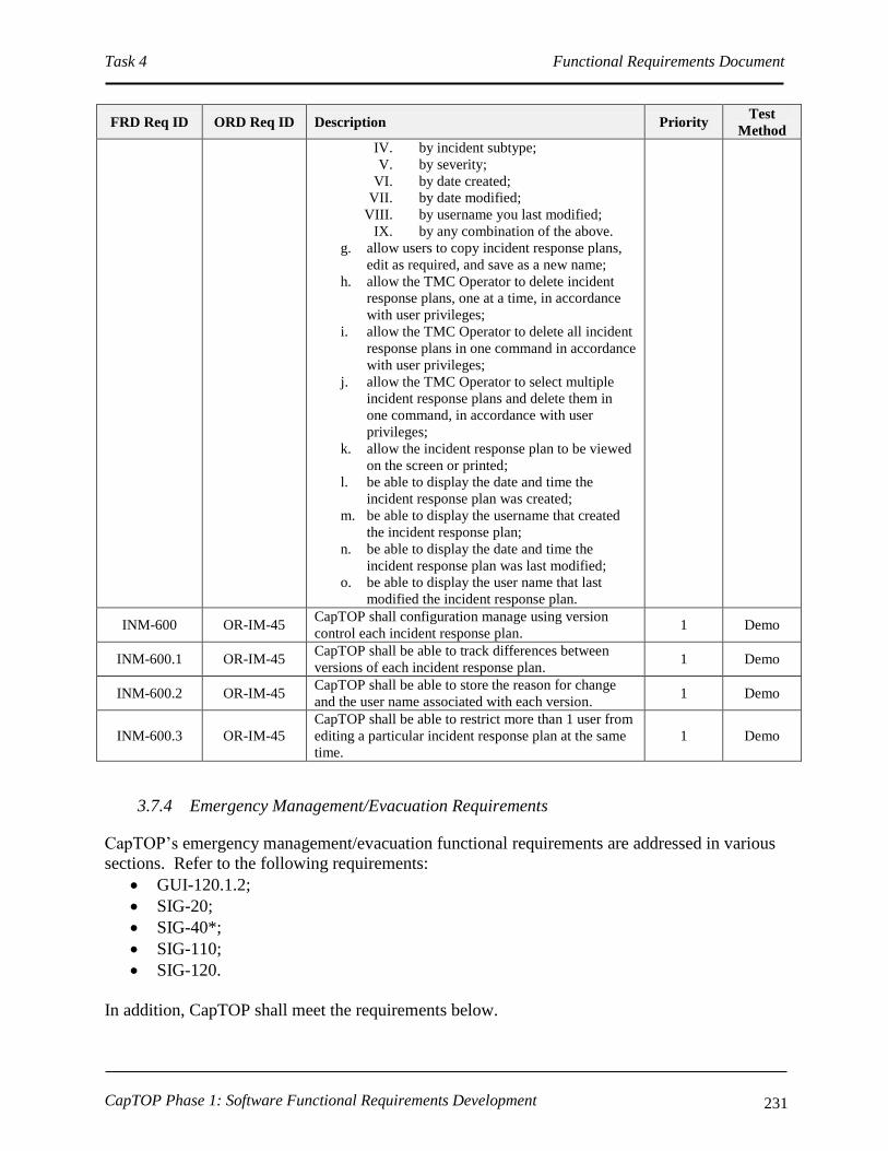
Task 4 Functional Requirements Document
CapTOP Phase 1: Software Functional Requirements Development 231
FRD Req ID ORD Req ID Description Priority Test
Method
IV. by incident subtype;
V. by severity;
VI. by date created;
VII. by date modified;
VIII. by username you last modified;
IX. by any combination of the above.
g. allow users to copy incident response plans,
edit as required, and save as a new name;
h. allow the TMC Operator to delete incident
response plans, one at a time, in accordance
with user privileges;
i. allow the TMC Operator to delete all incident
response plans in one command in accordance
with user privileges;
j. allow the TMC Operator to select multiple
incident response plans and delete them in
one command, in accordance with user
privileges;
k. allow the incident response plan to be viewed
on the screen or printed;
l. be able to display the date and time the
incident response plan was created;
m. be able to display the username that created
the incident response plan;
n. be able to display the date and time the
incident response plan was last modified;
o. be able to display the user name that last
modified the incident response plan.
INM-600 OR-IM-45 CapTOP shall configuration manage using version
control each incident response plan. 1 Demo
INM-600.1 OR-IM-45 CapTOP shall be able to track differences between
versions of each incident response plan. 1 Demo
INM-600.2 OR-IM-45 CapTOP shall be able to store the reason for change
and the user name associated with each version. 1 Demo
INM-600.3 OR-IM-45
CapTOP shall be able to restrict more than 1 user from
editing a particular incident response plan at the same
time.
1 Demo
3.7.4 Emergency Management/Evacuation Requirements
CapTOP’s emergency management/evacuation functional requirements are addressed in various
sections. Refer to the following requirements:
GUI-120.1.2;
SIG-20;
SIG-40*;
SIG-110;
SIG-120.
In addition, CapTOP shall meet the requirements below.
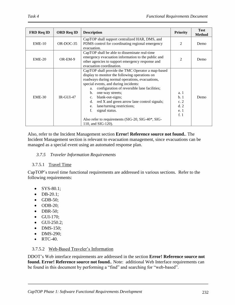
Task 4 Functional Requirements Document
CapTOP Phase 1: Software Functional Requirements Development 232
FRD Req ID ORD Req ID Description Priority Test
Method
EME-10 OR-DOC-35
CapTOP shall support centralized HAR, DMS, and
PDMS control for coordinating regional emergency
evacuation.
2 Demo
EME-20 OR-EM-9
CapTOP shall be able to disseminate real-time
emergency evacuation information to the public and
other agencies to support emergency response and
evacuation coordination.
2 Demo
EME-30 IR-GUI-47
CapTOP shall provide the TMC Operator a map-based
display to monitor the following operations on
roadways during normal operations, evacuations,
special events, and during incidents:
a. configuration of reversible lane facilities;
b. one-way streets;
c. blank-out-signs;
d. red X and green arrow lane control signals;
e. lane/turning restrictions;
f. signal status.
Also refer to requirements (SIG-20, SIG-40*, SIG-
110, and SIG-120).
a. 1
b. 1
c. 2
d. 2
e. 1
f. 1
Demo
Also, refer to the Incident Management section Error! Reference source not found.. The
Incident Management section is relevant to evacuation management, since evacuations can be
managed as a special event using an automated response plan.
3.7.5 Traveler Information Requirements
3.7.5.1 Travel Time
CapTOP’s travel time functional requirements are addressed in various sections. Refer to the
following requirements:
SYS-80.1;
DB-20.1;
GDB-50;
ODB-20;
DBR-50;
GUI-170;
GUI-250.2;
DMS-150;
DMS-290;
RTC-40.
3.7.5.2 Web-Based Traveler’s Information
DDOT’s Web interface requirements are addressed in the section Error! Reference source not
found. Error! Reference source not found.. Note: additional Web Interface requirements can
be found in this document by performing a “find” and searching for “web-based”.

Task 4 Functional Requirements Document
CapTOP Phase 1: Software Functional Requirements Development 233
3.7.5.3 Congestion and Traffic Condition Monitoring
CapTOP’s congestion and traffic condition monitoring functional requirements are addressed in
various sections. Refer to the following requirements:
CGA-10*;
DBA-20.1;
DWA-40;
DWA-40;
GDB-50;
GDB-50;
GUI-120.1 and GUI-120.1.1;
GUI-150*;
GUI-250.2 and 250.3;
GUI-260.1;
INM-530, 540, 560;
ODB-20;
PCS-50.1;
RTC-10;
RTC-20;
SPD-50.1;
SYS170;
SYS-200;
SYS-80.1;
TDA-10;
TDC-50.1;
TDS-50.1.
3.7.5.4 Special Event Management
The majority of CapTOP’s special event management requirements are captured in the Incident
Management Section Error! Reference source not found.. Refer to requirements INM-*. In
addition, refer to the requirements below which are also relevant to special event management:
SYS-140;
DBR-40;
GUI-120.1.1;
GUI-250.4;
GUI-350.2;
CCT-250.1;
DMS-130.1;
HAR-130.1
3.7.5.5 Incident Management
CapTOP’s incident management requirements are captured in the Incident Management Section
Error! Reference source not found.. Refer to requirements INM-*. In addition, in numerous

Task 4 Functional Requirements Document
CapTOP Phase 1: Software Functional Requirements Development 234
other sections incident management requirements are described. These requirements can be
found in this document by performing a “find” and searching for “incident”.
3.7.5.6 Dissemination Partners
The CapTOP system is designed to support information dissemination and sharing with
government agencies and private companies, including web-based traffic companies, regional
information clearing houses, and local, count, state, and federal governments. This is
accomplished through the use of center-to-center information sharing interfaces.
Refer to section Error! Reference source not found. Error! Reference source not found. for
additional information.
3.8 Interfaces to Other Systems/Applications within DDOT
3.8.1 CVISN/WIM Interface Requirements
CapTOP’s CVISN/WIM interface requirements are addressed in various sections. Refer to the
following requirements:
INM-100;
INM-100.7;
SYS-150.2;
SYS-160;
SYS-180;
CDB-10.1;
ODB-10.1;
DBR-70;
DBR-110
TDA-10.1.
CapTOP shall also support the CVISN interface through the standard CapTOP Web-Interface
available for remote users. In addition, CapTOP shall meet the requirements below.
FRD Req ID ORD Req ID Description Priority Test
Method
CVN-10 OR-CVSN-1
CapTOP shall be able to send MPD and other agencies
alerts and notifications when the determination is made
that a security threat exists due to an unauthorized
commercial vehicle that bypasses a inspection station.
2 Demo
CVN-20 OR-CVSN-2
CapTOP shall be able to send MPD and other agencies
alerts and notifications when a HAZMAT vehicle is
encountered.
2 Demo
CVN-30 OR-CVSN-3
CapTOP shall provide the TMC Operator with access
to information regarding height restrictions, weight
restrictions, and routes that are inappropriate for heavy
and oversized vehicles.
2 Demo
CVN-40 OR-CVSN-4
CapTOP shall be able to access and display truck
routes with weight restrictions on the CapTOP map
display.
2 Demo
CVN-50 OR-CVSN-5, CapTOP shall provide an interface with CVISN’s 2 overall, Demo

Task 4 Functional Requirements Document
CapTOP Phase 1: Software Functional Requirements Development 235
FRD Req ID ORD Req ID Description Priority Test
Method
OR-GUI-14,
OR-C2F-3,
OR-C2F-4,
OR-DOC-1,
SR-SYS-23
Roadside Operations Computers (ROCs) to access the
following CVISN information:
a. video;
b. vehicle data (speed, volume, classification
and weight);
c. overweight vehicle alarms (weigh-in-motion
data);
d. WIM station status (OK, failed);
e. messages displayed on CVISN’s DMS signs;
f. AVI data for monitoring movement at the
TMC for HAZMAT movements and
oversized/special permit vehicle movements.
3 for item
e
CVN-60 OR-CVSN-6
CapTOP shall be able to notify the TMC Operator of
overweight truck alarms received via an interface with
CVISN’s ROCs.
2 Demo
CVN-70 OR-CVSN-7,
OR-RTC-13
CapTOP shall provide an interface with the CVISN E-
Screening Program to access WIM information, store
in the CapTOP operations database, and report on real-
time overweight trucks.
2 Demo
CVN-80 OR-CVSN-8
CapTOP shall be able to access and display truck
routes with height restrictions on the CapTOP map
display.
2 Demo
CVN-90 OR-CVSN-9
CapTOP shall provide the following pre-trip incident
information to the CVO truckers and dispatchers
delivered via the Internet:
i. the following incident information along truck
routes:
1. accidents;
2. congestion;
3. construction activities;
4. special events;
5. road closures.
j. information on alternate routes in the event of
major incidents and special events;
k. special events that may affect truck routes;
l. maximum vehicle heights at low
bridges/underpasses;
m. weight restrictions displayed by road/location.
3 Demo
CVN-100 OR-CVSN-10
A CapTOP workstation shall be available at the
CVISN scale house to provide access to the following
general information:
d. incidents;
e. congested areas;
f. special events;
g. signal status;
h. ITS device status;
i. live video;
j. road closures;
k. lane closures;
l. construction zones;
m. maintenance operations;
n. traffic condition data;
o. weather-related road conditions;
p. weather-related warnings;
2 Demo
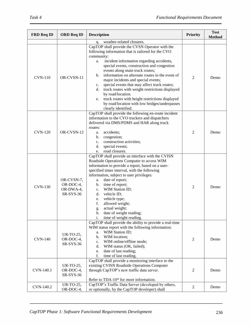
Task 4 Functional Requirements Document
CapTOP Phase 1: Software Functional Requirements Development 236
FRD Req ID ORD Req ID Description Priority Test
Method
q. weather-related closures.
CVN-110 OR-CVSN-11
CapTOP shall provide the CVSN Operator with the
following information that is tailored for the CVO
community:
a. incident information regarding accidents,
special events, construction and congestion
events along main truck routes;
b. information on alternate routes in the event of
major incidents and special events;
c. special events that may affect truck routes;
d. truck routes with weight restrictions displayed
by road/location.
e. truck routes with height restrictions displayed
by road/location with low bridges/underpasses
clearly identified.
2 Demo
CVN-120 OR-CVSN-12
CapTOP shall provide the following en-route incident
information to the CVO truckers and dispatchers
delivered via DMS/PDMS and HAR along truck
routes:
a. accidents;
b. congestion;
c. construction activities;
d. special events;
e. road closures.
2 Demo
CVN-130
OR-CVSN-7,
OR-DOC-4,
OR-DWA-4,
SR-SYS-36
CapTOP shall provide an interface with the CVISN
Roadside Operations Computer to access WIM
information to provide a report, based on a user-
specified timer interval, with the following
information, subject to user privileges:
a. date of report;
b. time of report;
c. WIM Station ID;
d. vehicle ID;
e. vehicle type;
f. allowed weight;
g. actual weight;
h. date of weight reading;
i. time of weight reading.
2 Demo
CVN-140
UR-TO-25,
OR-DOC-4,
SR-SYS-36
CapTOP shall provide the ability to provide a real-time
WIM status report with the following information:
a. WIM Station ID;
b. WIM location;
c. WIM online/offline mode;
d. WIM status (OK, failed);
e. date of last reading;
f. time of last reading.
2 Demo
CVN-140.1
UR-TO-25,
OR-DOC-4,
SR-SYS-36
CapTOP shall provide a monitoring interface to the
existing CVISN Roadside Operations Computer
through CapTOP’s new traffic data server.
Refer to TDA-10* for more information.
2 Demo
CVN-140.2 UR-TO-25,
OR-DOC-4,
CapTOP’s Traffic Data Server (developed by others,
or optionally, by the CapTOP developer) shall 2 Demo

Task 4 Functional Requirements Document
CapTOP Phase 1: Software Functional Requirements Development 237
FRD Req ID ORD Req ID Description Priority Test
Method
SR-SYS-36 interface with CVISN Roadside Operations Computer
to obtain real-time WIM data.
CVN-150 IR-GUI-26
CapTOP shall provide map-based displays that display
color-coded icons to reflect the real-time status for the
WIM stations.
2 Demo
CVN-150.1 IR-GUI-26
The icon color shall be green if the WIM station is
online with no overweight vehicles in the last 1
minute, gray if the WIM is offline, and red if the WIM
has had an overweight vehicle in the last 1 minute.
2 Demo
CVN-150.2 OR-DOC-1
CapTOP shall use data from the following sources to
determine operational status:
a. data reported from the CVISN Roadside
Operations Computer;
b. data gained by CapTOP in attempts to
communicate with the CVISN Roadside
Operations Computer;
c. online/offline information entered manually
by authorized CapTOP users.
2 Demo
CVN-160 OR-TDCA-20,
OR-TDCA-21
CapTOP shall allow the following WIM station
configuration data to be entered, stored, retrieved, and
printed:
a. WIM Station Number;
b. WIM Model Number;
c. Location Information;
I. Location Description;
II. Street Address;
III. Road Name;
IV. Road Direction;
V. Exit Number;
VI. Milepost;
VII. Intersection/Interchange.
d. Road Classification (interstate,
freeway/expressway, principal arterial, minor
arterial, collector, local);
e. Online-Offline Mode ( static – set by System
Administrator or Maintenance Technician);
f. Link ID;
g. Polling Enabled (yes/no, defaults to yes);
h. Associated CCTV;
i. TMDD Information;
I. Horizontal Datum (WGS84,
84EGM96, NAD83);
II. Latitude (decimal degrees);
III. Longitude (decimal degrees);
IV. Vertical Datum (WGS84);
V. Height (-127 to 127);
VI. Vertical Level (-127 to 127).
2 Demo

Task 4 Functional Requirements Document
CapTOP Phase 1: Software Functional Requirements Development 238
3.8.2 Tunnel Operations Center Interface Requirements
CapTOP’s interface requirements to the Supervisory Control and Data Acquisition (SCADA)
system supporting tunnel operations are described below. Also refer to requirements
SYS-80;
INM-100.9;
GUI-260..
FRD Req ID ORD Req ID Description Priority Test
Method
SCA-10 OR-TOPS-1
CapTOP shall provide an interface with the SCADA
system to monitor Carbon Monoxide (CO), drainage,
ventilation, and environmental conditions at the 3rd
Street, 9th Street and 12th Street Tunnels.
2 Demo
SCA-20 OR-TOPS-2
CapTOP shall provide an interface to receive
overheight vehicle notifications from the 3rd Street
Tunnel SCADA system.
2 Demo
SCA-30 OR-TOPS-3
CapTOP shall provide alarms to the user alerting of
overheight vehicle detections obtained from the 3rd
Street Tunnel SCADA system.
2 Demo
3.8.3 Streetcar System Interface Requirements
CapTOP’s Streetcar interface requirements are addressed in various sections. Refer to the
following requirements:
SYS-80;
GUI-260;
INM-100.
In addition, CapTOP shall meet the requirements below.
FRD Req ID ORD Req ID Description Priority Test
Method
STC-10 N/A
CapTOP shall provide an interface with the Streetcar
Operations Center to exchange traffic signal operation
information
2 Demo
STC-20 N/A
CapTOP shall provide an interface with the Streetcar
Operations Center to access streetcar location
information in real time.
2 Demo
STC-30 N/A CapTOP shall interface with the Streetcar Operations
Center through a Web-based interface. 2 Demo
STC-40 N/A
CapTOP shall provide an interface with the Streetcar
Operations Center to provide video streams and
control of a limited number of cameras in the vicinity
of streetcar lines subject to user privilege priority.
2 Demo
STC-50 N/A
CapTOP shall provide an interface with the Streetcar
Operations Center to accept video streams by cameras
on streetcars and stations.
2 Demo
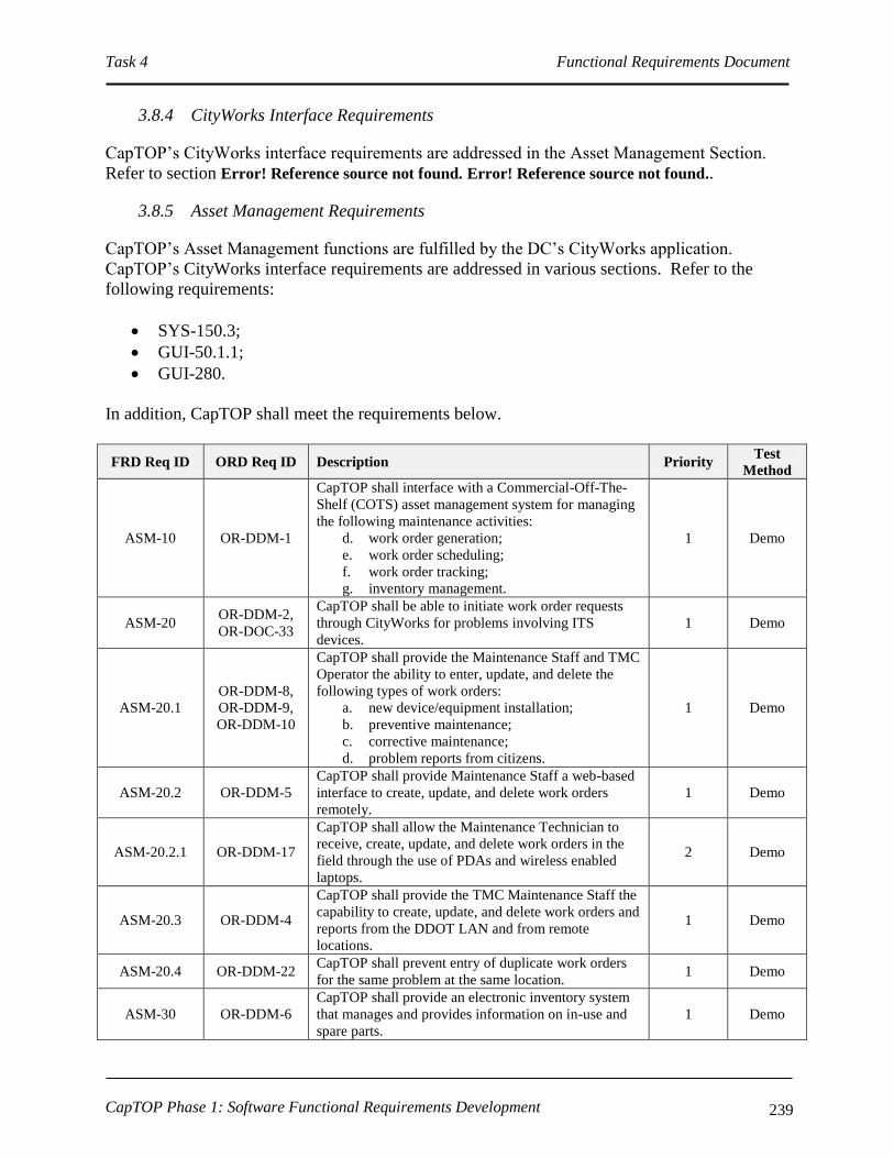
Task 4 Functional Requirements Document
CapTOP Phase 1: Software Functional Requirements Development 239
3.8.4 CityWorks Interface Requirements
CapTOP’s CityWorks interface requirements are addressed in the Asset Management Section.
Refer to section Error! Reference source not found. Error! Reference source not found..
3.8.5 Asset Management Requirements
CapTOP’s Asset Management functions are fulfilled by the DC’s CityWorks application.
CapTOP’s CityWorks interface requirements are addressed in various sections. Refer to the
following requirements:
SYS-150.3;
GUI-50.1.1;
GUI-280.
In addition, CapTOP shall meet the requirements below.
FRD Req ID ORD Req ID Description Priority Test
Method
ASM-10 OR-DDM-1
CapTOP shall interface with a Commercial-Off-The-
Shelf (COTS) asset management system for managing
the following maintenance activities:
d. work order generation;
e. work order scheduling;
f. work order tracking;
g. inventory management.
1 Demo
ASM-20 OR-DDM-2,
OR-DOC-33
CapTOP shall be able to initiate work order requests
through CityWorks for problems involving ITS
devices.
1 Demo
ASM-20.1
OR-DDM-8,
OR-DDM-9,
OR-DDM-10
CapTOP shall provide the Maintenance Staff and TMC
Operator the ability to enter, update, and delete the
following types of work orders:
a. new device/equipment installation;
b. preventive maintenance;
c. corrective maintenance;
d. problem reports from citizens.
1 Demo
ASM-20.2 OR-DDM-5
CapTOP shall provide Maintenance Staff a web-based
interface to create, update, and delete work orders
remotely.
1 Demo
ASM-20.2.1 OR-DDM-17
CapTOP shall allow the Maintenance Technician to
receive, create, update, and delete work orders in the
field through the use of PDAs and wireless enabled
laptops.
2 Demo
ASM-20.3 OR-DDM-4
CapTOP shall provide the TMC Maintenance Staff the
capability to create, update, and delete work orders and
reports from the DDOT LAN and from remote
locations.
1 Demo
ASM-20.4 OR-DDM-22 CapTOP shall prevent entry of duplicate work orders
for the same problem at the same location. 1 Demo
ASM-30 OR-DDM-6
CapTOP shall provide an electronic inventory system
that manages and provides information on in-use and
spare parts.
1 Demo
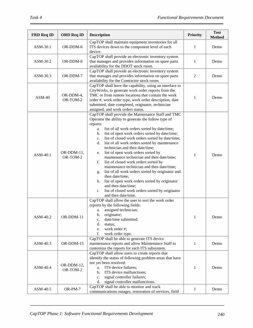
Task 4 Functional Requirements Document
CapTOP Phase 1: Software Functional Requirements Development 240
FRD Req ID ORD Req ID Description Priority Test
Method
ASM-30.1 OR-DDM-6
CapTOP shall maintain equipment inventories for all
ITS devices down to the component level of each
device.
1 Demo
ASM-30.2 OR-DDM-6
CapTOP shall provide an electronic inventory system
that manages and provides information on spare parts
availability for the DDOT stock room.
1 Demo
ASM-30.3 OR-DDM-7
CapTOP shall provide an electronic inventory system
that manages and provides information on spare parts
availability for the Contractor stock room.
2 Demo
ASM-40 OR-DDM-4,
OR-TOM-2
CapTOP shall have the capability, using an interface to
CityWorks, to generate work order reports from the
TMC or from remote locations that contain the work
order #, work order type, work order description, date
submitted, date completed, originator, technician
assigned, and work orders status.
1 Demo
ASM-40.1 OR-DDM-11,
OR-TOM-2
CapTOP shall provide the Maintenance Staff and TMC
Operator the ability to generate the follow type of
reports:
a. list of all work orders sorted by date/time;
b. list of open work orders sorted by date/time;
c. list of closed work orders sorted by date/time;
d. list of all work orders sorted by maintenance
technician and then date/time;
e. list of open work orders sorted by
maintenance technician and then date/time;
f. list of closed work orders sorted by
maintenance technician and then date/time;
g. list of all work orders sorted by originator and
then date/time;
h. list of open work orders sorted by originator
and then date/time;
i. list of closed work orders sorted by originator
and then date/time.
1 Demo
ASM-40.2 OR-DDM-11
CapTOP shall allow the user to sort the work order
reports by the following fields:
a. assigned technician;
b. originator;
c. date/time submitted;
d. status;
e. work order #;
f. work order type.
1 Demo
ASM-40.3 OR-DDM-15
CapTOP shall be able to generate ITS device
maintenance reports and allow Maintenance Staff to
customize the reports for each ITS subsystem.
1 Demo
ASM-40.4 OR-DDM-12,
OR-TOM-2
CapTOP shall allow users to create reports that
identify the status of following problem areas that have
not yet been resolved:
a. ITS device failures;
b. ITS device malfunctions;
c. signal controller failures;
d. signal controller malfunctions.
1 Demo
ASM-40.5 OR-PM-7 CapTOP shall be able to monitor and track
communications outages, restoration of services, field 1 Demo

Task 4 Functional Requirements Document
CapTOP Phase 1: Software Functional Requirements Development 241
FRD Req ID ORD Req ID Description Priority Test
Method
device operation and malfunction, and device
reliability.
ASM-50 OR-DDM-13
CapTOP shall be able to produce a problem report
(trouble ticket) and transmit to Maintenance Staff via
an integrated asset management system.
1 Demo
ASM-60 OR-DDM-23
CapTOP shall facilitate direct information exchange
between the TMC Operator and Maintenance Staff to
share information with regard to device problems,
device repair status, maintenance activity status, and
work order status.
1 Demo
ASM-60.1 OR-DDM-14
CapTOP shall provide the capability to allow the TMC
Operator to communicate with Maintenance
Technicians in the field and to obtain real-time device
status information to confirm maintenance repairs.
1 Demo
ASM-70 OR-DDM-14 CapTOP shall allow the TMC Operator to view the
status of any problem report. 1 Demo
ASM-80 OR-DDM-16
CapTOP shall be able to alert Maintenance Staff and
the TMC Operator when there is a field device
malfunction and the field device status transition as
follows:
a. from on-line to off-line;
b. from on-line to device failure;
c. from on-line to communication failure.
1 Demo
ASM-90 OR-DDM-18
CapTOP shall provide a seamless interface with the
CityWorks application to utilize its asset management
capabilities and features.
1 Demo
ASM-100 OR-DDM-25
CapTOP shall track status of maintenance trucks,
individuals and teams/shifts during emergencies and
special events.
2 Demo
ASM-110 OR-DDM-26 CapTOP shall log status changes of maintenance
trucks and maintenance teams during emergencies. 2 Demo
ASM-120 OR-DDM-28
CapTOP shall be able to track maintenance activity, by
asset, and by activity, for performance and budget
purposes.
1 Demo
ASM-130 OR-DDM-29
CapTOP shall provide the TMC Operator or the
Maintenance Technician with functions to query the
following information on ITS devices and equipment:
a. model number;
b. date purchased;
c. serial number;
d. original equipment manufacturer name,
address, phone number, web address;
e. seller's name, address, phone number, web
address;
f. warranty information;
g. repair history.
1 Demo
ASM-140 OR-DDM-30
CapTOP shall be able to track and accommodate
diagnostics for the following types of communication
links:
a. DSL circuits;
b. twisted pair circuits;
c. wireless communication links;
d. fiber optic links.
2 Demo

Task 4 Functional Requirements Document
CapTOP Phase 1: Software Functional Requirements Development 242
FRD Req ID ORD Req ID Description Priority Test
Method
ASM-150 OR-DDM-4
CapTOP shall have the ability to provide a
consolidated real-time status report that list the status
of each subsystem device to the CityWorks system.
Refer to each subsystem for additional details.
2 Demo
ASM-160 UR-TO-23
CapTOP shall provide the Maintenance Manager the
ability to perform the following:
a. manage the following maintenance resources:
1. vehicles;
2. spare parts;
3. personnel.
b. monitor Maintenance Technician activities;
c. supervise maintenance services provided by
Contractors;
d. communicate with other agencies to provide
field device status.
2 Demo
ASM-170 UR-TO-24
CapTOP shall provide the Maintenance Manager the
ability to create, schedule, and monitor the status of
work orders for Maintenance Technicians.
2 Demo
ASM-180 UR-TO-25
CapTOP shall provide the Maintenance Technician the
ability to monitor the performance and the status of the
following:
a. the following TMC equipment:
1. TMC workstations;
2. TMC servers;
3. TMC video equipment.
b. the following ITS field devices:
1. CCTV cameras;
2. DMS;
3. PDMS;
4. HAR;
5. RWIS;
6. traffic detection stations;
7. WIM sensors;
8. permanent count stations.
c. communication networks;
d. traffic signals.
1 Demo
3.8.5.1 Inventory Management
Refer to requirements ASM-10 and ASM-30*.
3.8.5.2 Repair and Maintenance
Refer to requirements ASM-50, ASM-60*, and ASM-150 through 180.
3.8.6 Interface to Signal Maintenance Contractor’s Work Order Database
CapTOP’s interface requirements to the Signal Contractor’s Maintenance Work Order Database
(currently McDean) are described below. Also refer to requirement SYS-150.3.
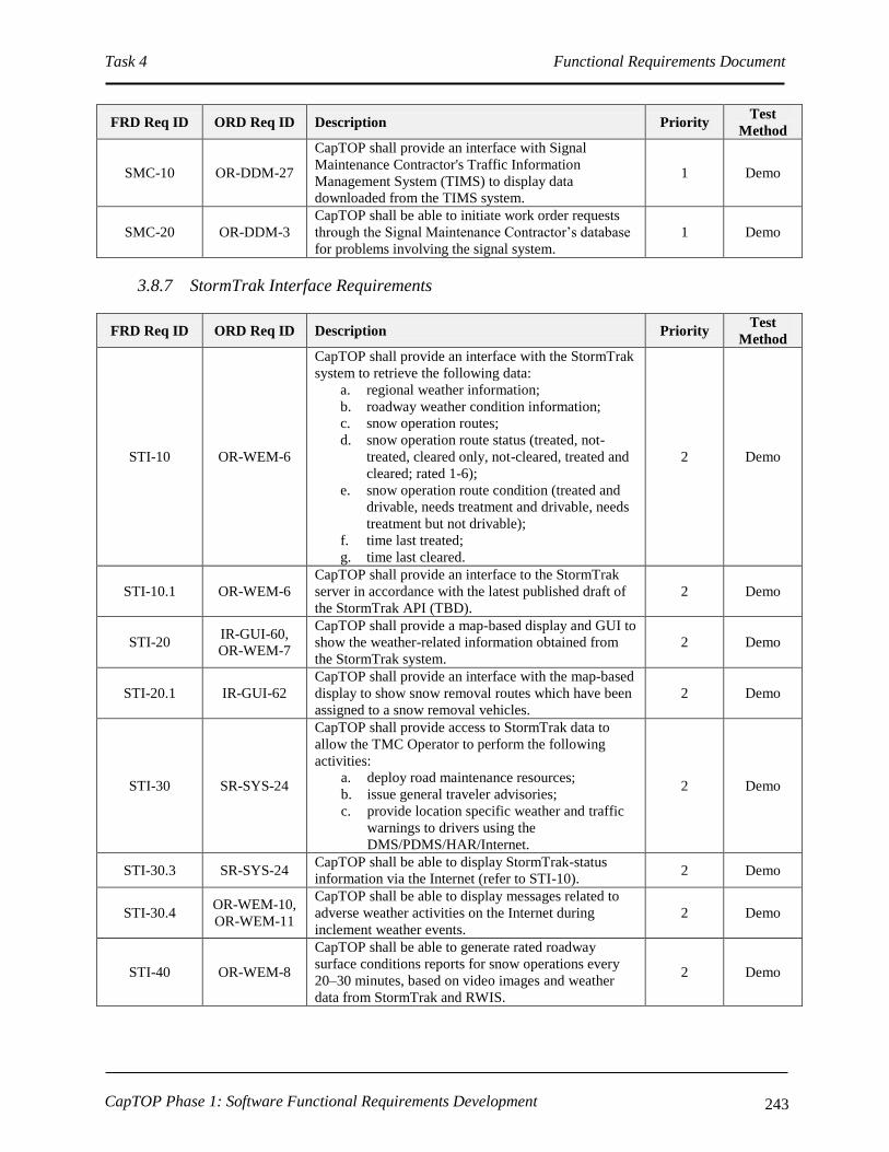
Task 4 Functional Requirements Document
CapTOP Phase 1: Software Functional Requirements Development 243
FRD Req ID ORD Req ID Description Priority Test
Method
SMC-10 OR-DDM-27
CapTOP shall provide an interface with Signal
Maintenance Contractor's Traffic Information
Management System (TIMS) to display data
downloaded from the TIMS system.
1 Demo
SMC-20 OR-DDM-3
CapTOP shall be able to initiate work order requests
through the Signal Maintenance Contractor’s database
for problems involving the signal system.
1 Demo
3.8.7 StormTrak Interface Requirements
FRD Req ID ORD Req ID Description Priority Test
Method
STI-10 OR-WEM-6
CapTOP shall provide an interface with the StormTrak
system to retrieve the following data:
a. regional weather information;
b. roadway weather condition information;
c. snow operation routes;
d. snow operation route status (treated, not-
treated, cleared only, not-cleared, treated and
cleared; rated 1-6);
e. snow operation route condition (treated and
drivable, needs treatment and drivable, needs
treatment but not drivable);
f. time last treated;
g. time last cleared.
2 Demo
STI-10.1 OR-WEM-6
CapTOP shall provide an interface to the StormTrak
server in accordance with the latest published draft of
the StormTrak API (TBD).
2 Demo
STI-20 IR-GUI-60,
OR-WEM-7
CapTOP shall provide a map-based display and GUI to
show the weather-related information obtained from
the StormTrak system.
2 Demo
STI-20.1 IR-GUI-62
CapTOP shall provide an interface with the map-based
display to show snow removal routes which have been
assigned to a snow removal vehicles.
2 Demo
STI-30 SR-SYS-24
CapTOP shall provide access to StormTrak data to
allow the TMC Operator to perform the following
activities:
a. deploy road maintenance resources;
b. issue general traveler advisories;
c. provide location specific weather and traffic
warnings to drivers using the
DMS/PDMS/HAR/Internet.
2 Demo
STI-30.3 SR-SYS-24 CapTOP shall be able to display StormTrak-status
information via the Internet (refer to STI-10). 2 Demo
STI-30.4 OR-WEM-10,
OR-WEM-11
CapTOP shall be able to display messages related to
adverse weather activities on the Internet during
inclement weather events.
2 Demo
STI-40 OR-WEM-8
CapTOP shall be able to generate rated roadway
surface conditions reports for snow operations every
20–30 minutes, based on video images and weather
data from StormTrak and RWIS.
2 Demo
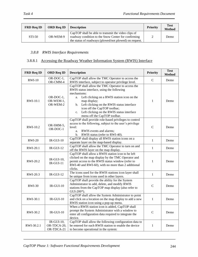
Task 4 Functional Requirements Document
CapTOP Phase 1: Software Functional Requirements Development 244
FRD Req ID ORD Req ID Description Priority Test
Method
STI-50 OR-WEM-9
CapTOP shall be able to transmit the video clips of
roadway condition to the Snow Center for confirming
the status of roadways (plowed/not plowed) on request.
2 Demo
3.8.8 RWIS Interface Requirements
3.8.8.1 Accessing the Roadway Weather Information System (RWIS) Interface
FRD Req ID ORD Req ID Description Priority Test
Method
RWI-10 OR-DOC-1,
OR-CMM-4
CapTOP shall allow the TMC Operator to access the
RWIS interface, subject to operator privilege level. C Demo
RWI-10.1
OR-DOC-1,
OR-WEM-1,
OR-WEM-2
CapTOP shall allow the TMC Operator to access the
RWIS status interface, using the following
mechanisms:
a. Left clicking on a RWIS station icon on the
map display;
b. Left clicking on the RWIS status interface
icon off the CapTOP toolbar;
c. Left clicking on the RWIS status interface
menu off the CapTOP toolbar.
1 Demo
RWI-10.2 OR-SMM-5,
OR-DOC-1
CapTOP shall provide role-based privileges to control
access to the following, subject to the user’s privilege
level:
a. RWIS events and alarms;
b. RWIS status (refer to RWI-40).
C Demo
RWI-20 IR-GUI-10 CapTOP shall display all RWIS station icons on a
separate layer on the map-based display. 1 Demo
RWI-20.1 IR-GUI-12 CapTOP shall allow the TMC Operator to turn on and
off the RWIS layer on the map display. 1 Demo
RWI-20.2 IR-GUI-10,
IR-GUI-11
CapTOP shall allow a RWIS station icon to be left
clicked on the map display by the TMC Operator and
permit access to the RWIS status window (refer to
RWI-40 and RWI-60), with no more than 2 additional
clicks.
1 Demo
RWI-20.3 IR-GUI-12 The icons used for the RWIS stations icon layer shall
be unique from icons used in other layers. 1 Demo
RWI-30 IR-GUI-10
CapTOP shall provide the ability for the System
Administrator to add, delete, and modify RWIS
stations from the CapTOP map display (also refer to
GUI-200*).
C Demo
RWI-30.1 IR-GUI-10
CapTOP shall allow the System Administrator to point
and click on a location on the map display to add a new
RWIS station icon using a pop-up menu.
1 Demo
RWI-30.2 IR-GUI-10
When a RWIS station icon is added, CapTOP shall
prompt the System Administrator with a window to
enter all configuration data required to integrate the
device.
C Demo
RWI-30.2.1
IR-GUI-10,
OR-TDCA-20,
OR-TDCA-21
CapTOP shall allow the following configuration data to
be entered for each RWIS station to enable the device
to become operational in the system:
1 Demo

Task 4 Functional Requirements Document
CapTOP Phase 1: Software Functional Requirements Development 245
FRD Req ID ORD Req ID Description Priority Test
Method
a. RWIS ID;
b. Description;
c. Controller Type;
d. Location Information:
I. Location Description;
II. Street Address;
III. Road Name;
IV. Road Direction;
V. Exit Number;
VI. Milepost;
VII. Intersection/Interchange (at least 2
streets, for roundabout will be more
than 2 streets).
e. Online-Offline Mode ( static – set by System
Administrator or Maintenance Technician);
f. Communication Type (dialup serial, network
serial, IP);
g. Multidrop Information;
I. Drop Address;
II. Channel ID;
III. Port Name.
h. IP Information;
I. IP Address;
II. Port Number.
i. Serial Information;
I. Baud Rate;
II. No. Data Bits;
III. Parity;
IV. No. Stop Bits;
V. H/W Flow Control;
VI. S/W Flow Control.
j. NTCIP Community;
k. Firmware Version;
l. Cabinet Number;
m. Controller Model Number;
n. Protocol;
o. Link ID;
p. Polling Enabled (yes/no, defaults to yes);
q. Comm Loss Timeout (seconds in .1
increments);
r. Associated CCTV;
s. TMDD Information;
I. Horizontal Datum (WGS84,
84EGM96, NAD83);
II. Latitude (decimal degrees);
III. Longitude (decimal degrees);
IV. Vertical Datum (WGS84);

Task 4 Functional Requirements Document
CapTOP Phase 1: Software Functional Requirements Development 246
FRD Req ID ORD Req ID Description Priority Test
Method
V. Height (-127 to 127);
VI. Vertical Level (-127 to 127).
RWI-30.2.2 IR-GUI-10
When a RWIS device icon is added, CapTOP shall
prompt the System Administrator or Maintenance
Technician with setting the device online or offline.
1 Demo
RWI-30.2.3 IR-GUI-10
If the user enters a latitude/longitude pair for the
device, the device icon location on the map shall be
updated automatically based on the coordinates
specified (and not where there user clicked to create the
icon).
1 Demo
RWI-30.3 IR-GUI-10,
IR-GUI-11
CapTOP shall allow a RWIS station icon to be right
clicked on the map display and permit access to the
following functions by the System Administrator or
Maintenance Technician, with no more than 2
additional clicks:
a. setting the online-offline mode;
b. entering, deleting, or modifying configuration
information;
c. allowing the device icon to be relocated on the
map display;
d. allowing the device icon to be deleted.
1 Demo
RWI-30.4 OR-IM-4
CapTOP shall strictly enforce the use of pull-down
menus, radio buttons, or selection boxes when any of
the following fields are entered by the user:
a. Street Address/Block;
b. Road Name;
c. Road Direction;
d. Exit Number;
e. Milepost;
f. Intersection/Interchange;
g. Online-Offline Mode (online/offline);
h. Communication Type (dialup serial, network
serial, IP);
i. Protocol;
j. Link ID;
k. Polling Enabled (yes/no, defaults to yes);
l. Associated CCTV.
1 Demo
RWI-30.4.1 OR-IM-4 CapTOP shall restrict the use of free-form text entry on
the fields identified above. 1 Demo
RWI-30.4.2 OR-IM-4
CapTOP shall allow the user to type the 1st 3 characters
in each field and the system will provide a filtered list
of selections for that field that begin with the 1st 3
characters typed by the user.
2 Demo
RWI-30.4.3 OR-IM-4
CapTOP shall allow the user to select “Other” and
enter in free form text when a desired entry cannot be
found in the list.
1 Demo
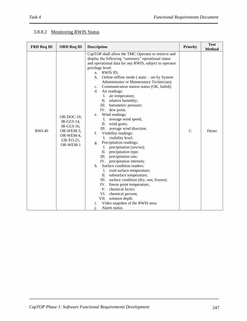
Task 4 Functional Requirements Document
CapTOP Phase 1: Software Functional Requirements Development 247
3.8.8.2 Monitoring RWIS Status
FRD Req ID ORD Req ID Description Priority Test
Method
RWI-40
OR-DOC-10,
IR-GUI-14,
IR-GUI-16,
OR-WEM-3,
OR-WEM-4,
UR-TO-25,
OR-WEM-1
CapTOP shall allow the TMC Operator to retrieve and
display the following “summary” operational status
and operational data for any RWIS, subject to operator
privilege level:
a. RWIS ID;
b. Online-offline mode ( static – set by System
Administrator or Maintenance Technician);
c. Communication station status (OK, failed);
d. Air readings:
I. air temperature;
II. relative humidity;
III. barometric pressure;
IV. dew point.
e. Wind readings:
I. average wind speed;
II. wind gusts;
III. average wind direction.
f. Visibility readings:
I. visibility level.
g. Precipitation readings:
I. precipitation (yes/no);
II. precipitation type;
III. precipitation rate;
IV. precipitation intensity.
h. Surface condition readers:
I. road surface temperature;
II. subsurface temperature;
III. surface condition (dry, wet, frozen);
IV. freeze point temperature;
V. chemical factor;
VI. chemical percent;
VII. solution depth.
i. Video snapshot of the RWIS area;
j. Alarm status.
C Demo
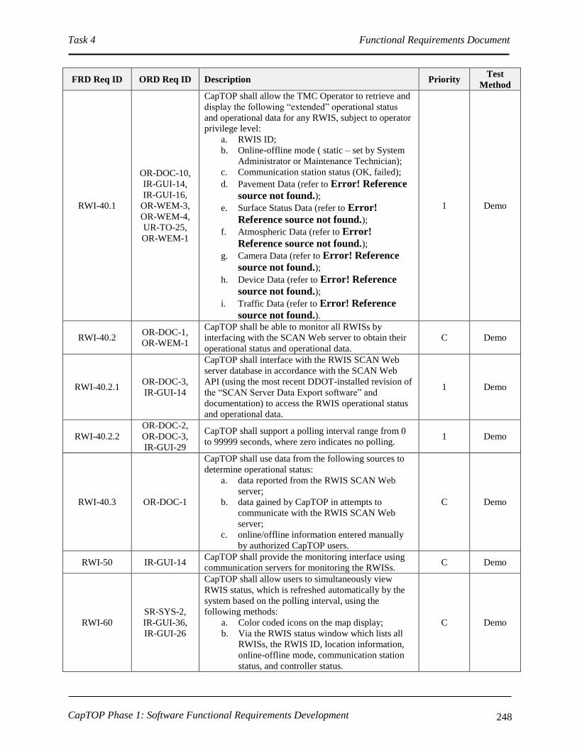
Task 4 Functional Requirements Document
CapTOP Phase 1: Software Functional Requirements Development 248
FRD Req ID ORD Req ID Description Priority Test
Method
RWI-40.1
OR-DOC-10,
IR-GUI-14,
IR-GUI-16,
OR-WEM-3,
OR-WEM-4,
UR-TO-25,
OR-WEM-1
CapTOP shall allow the TMC Operator to retrieve and
display the following “extended” operational status
and operational data for any RWIS, subject to operator
privilege level:
a. RWIS ID;
b. Online-offline mode ( static – set by System
Administrator or Maintenance Technician);
c. Communication station status (OK, failed);
d. Pavement Data (refer to Error! Reference
source not found.);
e. Surface Status Data (refer to Error!
Reference source not found.);
f. Atmospheric Data (refer to Error!
Reference source not found.);
g. Camera Data (refer to Error! Reference
source not found.);
h. Device Data (refer to Error! Reference
source not found.);
i. Traffic Data (refer to Error! Reference
source not found.).
1 Demo
RWI-40.2 OR-DOC-1,
OR-WEM-1
CapTOP shall be able to monitor all RWISs by
interfacing with the SCAN Web server to obtain their
operational status and operational data.
C Demo
RWI-40.2.1 OR-DOC-3,
IR-GUI-14
CapTOP shall interface with the RWIS SCAN Web
server database in accordance with the SCAN Web
API (using the most recent DDOT-installed revision of
the “SCAN Server Data Export software” and
documentation) to access the RWIS operational status
and operational data.
1 Demo
RWI-40.2.2
OR-DOC-2,
OR-DOC-3,
IR-GUI-29
CapTOP shall support a polling interval range from 0
to 99999 seconds, where zero indicates no polling. 1 Demo
RWI-40.3 OR-DOC-1
CapTOP shall use data from the following sources to
determine operational status:
a. data reported from the RWIS SCAN Web
server;
b. data gained by CapTOP in attempts to
communicate with the RWIS SCAN Web
server;
c. online/offline information entered manually
by authorized CapTOP users.
C Demo
RWI-50 IR-GUI-14 CapTOP shall provide the monitoring interface using
communication servers for monitoring the RWISs. C Demo
RWI-60
SR-SYS-2,
IR-GUI-36,
IR-GUI-26
CapTOP shall allow users to simultaneously view
RWIS status, which is refreshed automatically by the
system based on the polling interval, using the
following methods:
a. Color coded icons on the map display;
b. Via the RWIS status window which lists all
RWISs, the RWIS ID, location information,
online-offline mode, communication station
status, and controller status.
C Demo

Task 4 Functional Requirements Document
CapTOP Phase 1: Software Functional Requirements Development 249
FRD Req ID ORD Req ID Description Priority Test
Method
RWI-60.1
IR-GUI-28,
IR-GUI-26
CapTOP shall use the following colors for device icon
states:
a. Green = online;
b. Red = device failure;
c. Yellow = communication failure;
d. Gray = offline.
C Demo
RWI-60.1.1
IR-GUI-28,
IR-GUI-26
CapTOP shall use the following rules for device icon
states:
a. If the device is online but in communication
failure, the device icon color should be that of
a device with a communication failure;
b. In order for the device icon to be green, the
device must be both online and have OK
communication.
1 Demo
RWI-60.2 IR-GUI-31,
IR-GUI-29
The refresh rate for the status of the icons and for the
data in the status window shall be configurable and
based upon the polling rate.
1 Demo
RWI-60.3 IR-GUI-31
CapTOP shall allow the user to obtain summary status
information (refer to RWI-40 for the list of fields) by
hovering over an RWIS icon.
1 Demo
RWI-60.4 IR-GUI-29
CapTOP shall allow the user to select on any RWIS in
the RWIS status window (refer to RWI-60 item b) and
view all details (full status, configuration information)
pertaining to that RWIS.
1 Demo
RWI-70
SR-SYS-2,
IR-GUI-31,
IR-GUI-32
CapTOP shall provide a menu option to search for a
RWIS by the following methods:
a. by RWIS ID;
b. by IP address/drop address/channel ID of the
controller;
c. by street name;
d. by geographical address;
e. by intersection/interchange.
1 Demo
RWI-70.1 SR-SYS-2,
IR-GUI-31
CapTOP shall allow the TMC Operator to search for
RWISs using a rubber-band style box on the map
display to search an area.
1 Demo
RWI-70.2 SR-SYS-2,
IR-GUI-31
The result of each search shall be a list of RWISs that
are sorted, by default, by RWIS ID. 1 Demo
RWI-70.3 SR-SYS-2,
IR-GUI-31
The result of each search shall be a list of RWISs
sortable by RWIS ID, IP address/drop address/channel
ID, street name, geographical address, and
intersection/interchange.
1 Demo
RWI-80
OR-C2F-3,
OR-C2F-4,
OR-DWA-13
CapTOP shall be able to store RWIS operational status
and operational data (refer to RWI-40) in the CapTOP
operations database.
C Demo
RWI-90 OR-WEM-5
CapTOP shall provide an RWIS alert under the
following conditions:
a. Whenever there is precipitation of any type
from any RWIS station, and when the surface
temperate and ambient temperatures are 32
degrees Fahrenheit and below.
b. Whenever precipitation is detected from any
RWIS station that is snow, sleet, or ice.
1 Demo

Task 4 Functional Requirements Document
CapTOP Phase 1: Software Functional Requirements Development 250
FRD Req ID ORD Req ID Description Priority Test
Method
RWI-90.1 OR-WEM-5
CapTOP shall provide a configurable user distribution
list for each alert, along with the ability to send those
alerts to each distribution list.
1 Demo
RWI-90.2 OR-WEM-5 CapTOP shall ensure that alerts are not transmitted
repeatedly for the same weather event. 1 Demo
TABLE 9 Extended Status Data Definitions for RWIS Stations
Pavement Data
Data Type Abbr. Definition
Surface Status Status Condition of the pavement surface
Surface
Temperature Sfc Temperature of the pavement sensor roughly 3 mm (1/8 inch) below the surface of the sensor.
Subsurface
Temperature Sub
Typically, the temperature approximately 43 cm (17 inches) below the top of the pavement.
You can place additional subsurface sensors at different depths to monitor frost depth.
Subsurface
Moisture Moisture
The sub-surface moisture expressed as a percentage (eg. 0 indicates dry, 100 indicates
saturated). This value is only displayed for NTCIP sites configured with the appropriate sensor.
Delta Time Delta T Raw measurement from the Time Domain Reflectometry MP-917 Soil Moisture probe. This
value is only displayed for NTCIP sites configured with the appropriate sensor.
Freeze Point Frz
Freezing point of the moisture on the pavement sensor based upon the specific chemical in use.
This field is reported when the surface status is Wet, Chemical Wet, or Snow/Ice Warning.
Only reported by the FP2000 and active sensors.
Chemical
Percent Chem
Percent of chemical saturation in the moisture. This field is reported when the surface status is
Wet, Chemical Wet, or Snow/Ice Warning. Only reported by the FP2000 sensor.
Ice Percentage Ice
Percent of ice in the moisture. When ice percentage is roughly 50% to 85%, you would
typically call the surface moisture "slush". This field is reported when the surface status is Wet,
Chemical Wet, or Snow/Ice Warning. Only reported by the FP2000 sensor.
Depth Dpth
Depth of water layer on the sensor. This field is reported when the surface status is Wet,
Chemical Wet, or Snow/Ice Warning and the surface temperature is above the freeze point
temperature. Only reported by the FP2000 sensor.
Chemical
Factor CF
Relative indication of chemical present in the moisture on the surface. Chemical factor uses a
relative scale ranging from 0 to 100.
Conductivity Cond The conductance of the ice/liquid mixture on the pavement. This value is only displayed for
NTCIP sites configured with the appropriate sensor.

Task 4 Functional Requirements Document
CapTOP Phase 1: Software Functional Requirements Development 251
Pavement Data
Data Type Abbr. Definition
Salinity Salin
Salinity is roughly the number of grams of dissolved matter per kilogram of seawater. Units
shown in parts per 100,000. This value is only displayed for NTCIP sites configured with the
appropriate sensor.
The following surface status codes are listed in order of severity with the most critical status listed
first
Surface Status Data
Status Description
Snow/Ice Warning
Continuous film of ice and water mixture at or below freezing (32°F / 0°C) with insufficient
chemical to keep the mixture from freezing.
This status can only be reported at SSI ESP and SP sites when precipitation occurs.
Ice Warning
Continuous film of ice and water mixture at or below freezing (32°F / 0°C) with insufficient
chemical to keep the mixture from freezing.
This status can only be reported at NTCIP sites.
Snow Warning This status can be reported at NTCIP sites, but will not be reported by SSI NTCIP sites.
Wet Below Freezing Moisture on pavement sensor with a surface temperature below freezing (32°F / 0°C).
This status will only be reported at SSI SCAN Detector sites.
Frost
Moisture on pavement at or below freezing (32°F / 0°C) with a pavement temperature at or
below the dew point temperature.
This status can only be reported by SSI ESP, SP, and NTCIP sites when precipitation is not
occurring.
Ice Watch Thin or spotty film of moisture at or below freezing (32°F / 0°C).
This status can only be reported at NTCIP sites when precipitation is not occurring.
Snow Watch This status can be reported at NTCIP sites, but is not detected at SSI NTCIP sites.
Snow/IceWatch
Thin or spotty film of moisture at or below freezing (32°F / 0°C).
This status can only be reported at SSI ESP and SP sites when precipitation is not
occurring.
Chemical Wet
Continuous film of water and ice mixture at or below freezing (32°F or 0°C) with enough
chemical to keep the mixture from freezing.
This status can only be reported by SSI ESP, SP, and NTCIP sites when precipitation
occurs.
Wet
Continuous film of moisture on the pavement sensor with a surface temperature above
freezing (32°F or 0°C).
This status can be reported by SSI ESP, SP, SCAN Detector, and NTCIP sites when
precipitation has occurred.
Damp
Thin or spotty film of moisture above freezing (32°F or 0°C).
This status can only be reported by SSI ESP, and SP sites when precipitation is not
occurring.
Trace Moisture
Thin or spotty film of moisture above freezing (32°F or 0°C). Surface moisture occurred
without precipitation being detected.
This status will only be reported at NTCIP sites when precipitation is not occurring.
Absorption at Dew Point,
Absorption, & Dew
These statuses can be reported at NTCIP sites, but are not currently detected at SSI NTCIP
sites.

Task 4 Functional Requirements Document
CapTOP Phase 1: Software Functional Requirements Development 252
Surface Status Data
Status Description
Dry Absence of moisture on the surface sensor.
This status can be reported by SSI ESP, SP, SCAN Detector, and NTCIP sites.
Other
Other is the standard NTCIP ESS surface condition code to handle conditions not explicitly
included in this table. This status will only be reported NTCIP by sensors installed at
NTCIP ESS sites.
No Report The surface sensor is not operating properly and requires maintenance.
This status will only be reported by SSI ESP and SP sites.
Error The surface sensor is not operating properly and requires maintenance.
This status will only be reported by NTCIP sites.
Atmospheric Data Definitions
Data Type Abbr. Definition
Air
Temperature Air Air temperature at the site.
Max Temp Max The maximum temperature recorded during the 24 hours preceding the observation. This
value is only displayed for NTCIP sites configured with the appropriate sensor.
Min Temp Min The minimum temperature recorded during the 24 hours preceding the observation. This
value is only displayed for NTCIP sites configured with the appropriate sensor.
Dew Point
Temperature Dew
Temperature at which the air becomes saturated as it cools. If the road or runway
temperature drops to or below the dew point, moisture may develop on the surface. The
form the moisture takes depends on the surface temperature and the amount of chemical
present.
Relative
Humidity RH
Percent of moisture in the air. A relative humidity of 0% shows that the air contains no
moisture and 100% shows that the air is completely saturated and cannot absorb more
moisture.
Wind Chill
Factor WndChll Forecasted Wind Chill Factor.
Heat Index Heat Forecasted Heat Index.
Wind Speed SpdAvg Average speed of the wind during an evaluation cycle.
Wind Direction DirAvg
Average wind direction during an evaluation cycle. Wind direction can be displayed in two
formats: cardinal points or degrees. Cardinal format has 8 possible headings. Degree format
displays wind direction in values ranging from 1 to 360.
Direction Cardinal Format Degree Range
North N 338 - 22
Northeast NE 23 - 68

Task 4 Functional Requirements Document
CapTOP Phase 1: Software Functional Requirements Development 253
Atmospheric Data Definitions
Data Type Abbr. Definition
East E 69 - 112
Southeast SE 113 - 158
South S 159 - 202
Southwest SW 203 - 248
West W 249 - 292
Northwest NW 293 - 337
Gust SpdGst Maximum wind speed measured during an evaluation cycle. The time period over which
wind gust speed is monitored can vary based on the type and manufacturer of the RWIS site.
Probability of
Precipitation Prob Likelihood of precipitation during a forecasted period.
Cloud Cover Cloud
Cover Forecasted cloud cover percentage during a period.
Precipitation
Type Precip
Type of precipitation detected by a precipitation sensor, if one is available. Certain types of
precipitation sensors can only detect the presence or absence of precipitation and will
display Yes or No. Other types of precipitation sensors, such as the Weather Identifier and
Visibility Sensor (WIVIS) or Optical Weather Identifier (OWI), can classify the type of
precipitation and will report a specific type of precipitation. The WIVIS and OWI
precipitation sensors may report Yes at the onset of precipitation until sufficient time has
elapsed to classify the precipitation type.
Precipitation
Rate Rate
Average precipitation rate computed every minute. Snowfall is converted to water
equivalent and the rate represents the rate of liquid equivalent.
Precipitation
Intensity Intens
Intensity of the precipitation as derived from the precipitation rate. The National Weather
Service defines the following intensity classes: light, moderate, or heavy.
Time Since Last
Precip TimeSince
The time interval since the last precipitation event occurred. This value is not supported for
NTCIP sites.
Precipitation
Start Time StartTime
The time at which the most recent precipitation event began. This value is only displayed for
NTCIP sites configured with the appropriate sensor.
Precipitation
End Time EndTime
The time at which the most recent precipitation event ended. This value is only displayed for
NTCIP sites configured with the appropriate sensor.
Precipitation
Accumulation Accum
Rainfall amount or snowfall liquid equivalent for the period from midnight GMT to the
current time. At midnight GMT the total accumulation is reset to zero. See the accumulation
definitions below for the proper NTCIP accumulation definitions.
Snow Depth Snow
Depth
The depth of snow on representative areas other than the highway pavement, avoiding drifts
and plowed areas. Snow depth is only supported at NTCIP sites.

Task 4 Functional Requirements Document
CapTOP Phase 1: Software Functional Requirements Development 254
Atmospheric Data Definitions
Data Type Abbr. Definition
Snow
Accumulation
Snow
Accum Forecasted snowfall accumulation during a forecast period.
10 Minute
Precip Accum 10 min
Rainfall amount or snowfall liquid equivalent for the previous 10 minute period. This value
is only displayed for NTCIP sites configured with the appropriate sensor.
1 Hour Precip
Accum 1hr
Rainfall amount or snowfall liquid equivalent for the previous 1 hour period. This value is
only displayed for NTCIP sites configured with the appropriate sensor.
3 Hour Precip
Accum 3hr
Rainfall amount or snowfall liquid equivalent for the previous 3 hour period. This value is
only displayed for NTCIP sites configured with the appropriate sensor.
6 Hour Precip
Accum 6hr
Rainfall amount or snowfall liquid equivalent for the previous 6 hour period. This value is
only displayed for NTCIP sites configured with the appropriate sensor.
12 Hour Precip
Accum 12hr
Rainfall amount or snowfall liquid equivalent for the previous 12 hour period. This value is
only displayed for NTCIP sites configured with the appropriate sensor.
24 Hour Precip
Accum 24hr
Rainfall amount or snowfall liquid equivalent for the previous 24 hour period. This value is
only displayed for NTCIP sites configured with the appropriate sensor.
Barometric
Pressure BaroPs
The force per unit area exerted by the atmosphere. This reading is not adjusted for site
elevation.
10 Minute Solar
Radiation
10 Min
Rad
The direct solar radiation integrated over the preceding 10 minutes. This value is only
displayed for NTCIP sites configured with the appropriate sensor.
24 Hour Solar
Radiation 24 Hr Rad
The direct solar radiation integrated over the preceding 24 hours. This value is only
displayed for NTCIP sites configured with the appropriate sensor.
Total Sun Sun The total amount of sunshine in minutes over the preceding 24 hours. This value is only
displayed for NTCIP sites configured with the appropriate sensor.
Visibility Vis Average distance that you can see, both day and night, computed every three minutes.
Wet Bulb
Temp. WtBlb
The wet bulb temperature is the temperature of a thermometer whose bulb is wrapped in wet
muslin. The wetbulb is always in between the temperature and dew point, except at
saturation, when all three are equivalent. This value is only displayed for NTCIP sites
configured with the appropriate sensor.
Water Level Height Water level height is the relative water level height from the water level sensor's calibrated
"normal" height.
Ozone Ozone Concentration of ozone in the air as a fraction of volume. Shown in parts per billion.
The following Bridge Sprayer definitions only apply to NTCIP sites.

Task 4 Functional Requirements Document
CapTOP Phase 1: Software Functional Requirements Development 255
Bridge Spray Data
Data Type Abbr. Definition
Sprayer Status Status Status of the bridge sprayer control system.
Last Activation Last
Activation Date and Time the RWIS requested the bridge sprayer to be activated.
Start Time Start Time
Date and time the bridge sprayer began the chemical application cycle. Start Time will
only be reported for bridge sprayers configured to provide sprayer feedback to the
RWIS site.
End Time End Time
Date and time the bridge sprayer completed the chemical application cycle. End Time
will only be reported for bridge sprayers configured to provide sprayer feedback to the
RWIS site.
Tank Level Tank Level The amount of deicing chemical remaining in the bridge sprayer holding tank. Tank
Level is only reported by a bridge sprayer connected via a Bridge Sprayer Controller.
Tank Level Start Start
The amount of deicing chemical present in the bridge sprayer holding tank at the start
of a spray event. Only reported by a bridge sprayer connected via a Bridge Sprayer
Controller.
Tank Level End End
The amount of deicing chemical present in the bridge sprayer holding tank at the
completion of a spray event. Only reported by a bridge sprayer connected via a Bridge
Sprayer Controller.
Tank Level
Amount Amount
The amount of deicing chemical used during a spray event. Only reported by a bridge
sprayer connected via a Bridge Sprayer Controller.
Line Pressure Line Pressure The line pressure reported by the bridge sprayer in pounds per square inch. Line
Pressure is only reported by a bridge sprayer connected via a Bridge Sprayer Controller.
Average Line
Pressure Average
The average line pressure reported by the bridge sprayer during a spray event. Only
reported by a bridge sprayer connected via a Bridge Sprayer Controller.
Low Line
Pressure Low
The lowest line pressure reported by the bridge sprayer during a spray event. Only
reported by a bridge sprayer connected via a Bridge Sprayer Controller.
High Line
Pressure High
The highest line pressure reported by the bridge sprayer during a spray event. Only
reported by a bridge sprayer connected via a Bridge Sprayer Controller.
Flow Since Last
Event Flow Since
The amount of chemical that has leaked (as reported by the flow sensor) since the
completion of the last spray event. This counter will reset after each firing and when the
sprayer or RPU is restarted. This value is only reported by a bridge sprayer connected
via a Bridge Sprayer Controller.
Average Flow
Rate Average
The average chemical applied per minute by the bridge sprayer during a sprayer
event. Only reported by a bridge sprayer connected via a Bridge Sprayer Controller.
Low Flow Rate Low The lowest flow rate reported by the bridge sprayer during a sprayer event. Only
reported by a bridge sprayer connected via a Bridge Sprayer Controller.
High Flow Rate High The highest flow rate reported by the bridge sprayer during a sprayer event. Only
reported by a bridge sprayer connected via a Bridge Sprayer Controller.
Requested by Requested by The SCAN Web user that manually requested a bridge sprayer configuration change.
User Activation User
Activation The SCAN Web user that manually requested a bridge sprayer activation.
Request Request The date and time that a bridge sprayer configuration change was requested by a SCAN

Task 4 Functional Requirements Document
CapTOP Phase 1: Software Functional Requirements Development 256
Bridge Spray Data
Data Type Abbr. Definition
Date/Time Date/Time Web user.
Effective
Date/Time
Effective
Date/Time
The date and time that a user requested bridge sprayer configuration change was
delivered to the RWIS site. An * will be displayed if the configuration was not
delivered to the site.
Sprayer Mode Mode
Bridge sprayers can be configured in one of three modes: Automatic, On Demand, and
Disabled. Automatic mode also allows On Demand requests from the SCAN Web
Bridge Sprayer Activation page.
Max Operating
Temperature
Max
Temperature
The upper bound of the operational surface temperature range that controls whether the
bridge sprayer can be automatically activated.
Min Operating
Temperature
Min
Temperature
The lower bound of the operational surface temperature range that controls whether the
bridge sprayer can be automatically activated.
Wind Speed
Hold Off
Wind Speed
Hold Off
The maximum wind speed under which the bridge sprayer is configured to
automatically activate.
Freeze
Temperature
Offset
Freeze Temp
Offset
Activate sprayer when the surface temperature is within this many degrees or is less
than the freeze point. A negative value can be specified to delay the automatic
activation of the sprayer.
Freeze
Condition Hold
Off
Freeze Hold
Off
Number of minutes required to elapse before reactivating the sprayer due to a freeze
condition.
Dew Point
Offset
Dew Point
Offset
Activate sprayer when the surface temperature is within this many degrees or is less
than the dew point. A negative value can be specified to delay the automatic activation
of the sprayer.
Frost Condition
Hold Off Frost Hold Off
Number of minutes required to elapse before reactivating the sprayer due to a frost
condition.
The following bridge sprayer status codes are only supported for bridge sprayers installed at NTCIP
sites.
Bridge Sprayer Status Data
Sprayer Status Description
Spraying
Feedback status from the bridge sprayer indicates the sprayer is currently applying chemical.
This status will be reported after each activation status listed below or if the sprayer has been
activated from an external source. The sprayer must provide activation feedback to report this
status.
Waiting for confirmation
to spray
Before a request for sprayer activation occurs, the RPU must detect conditions that meet one
of the automatic sprayer activation definitions for two consecutive sensor evaluation cycles.
This status will be reported when the RPU initially detects the conditions. Once the conditions
are confirmed, the RPU will request the sprayer is activated and the proper activation status
will be displayed.
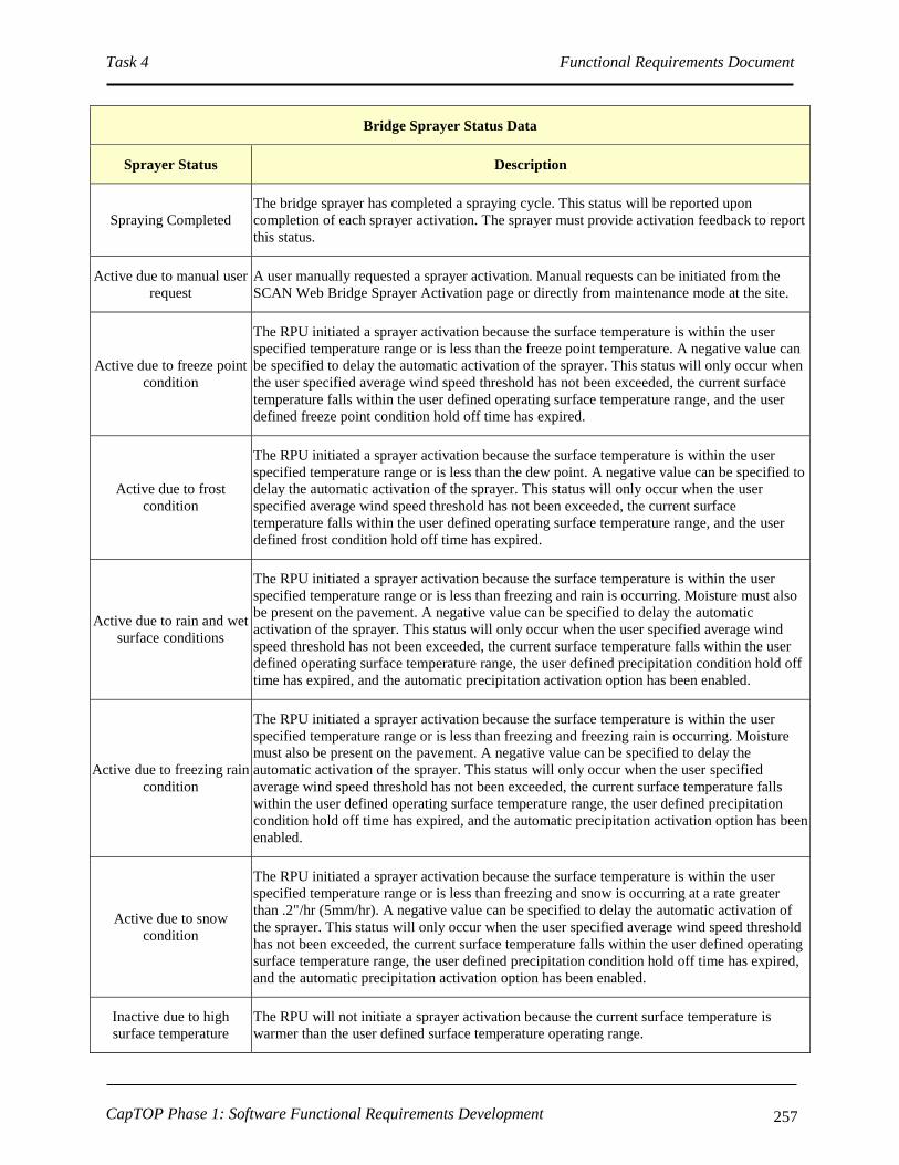
Task 4 Functional Requirements Document
CapTOP Phase 1: Software Functional Requirements Development 257
Bridge Sprayer Status Data
Sprayer Status Description
Spraying Completed
The bridge sprayer has completed a spraying cycle. This status will be reported upon
completion of each sprayer activation. The sprayer must provide activation feedback to report
this status.
Active due to manual user
request
A user manually requested a sprayer activation. Manual requests can be initiated from the
SCAN Web Bridge Sprayer Activation page or directly from maintenance mode at the site.
Active due to freeze point
condition
The RPU initiated a sprayer activation because the surface temperature is within the user
specified temperature range or is less than the freeze point temperature. A negative value can
be specified to delay the automatic activation of the sprayer. This status will only occur when
the user specified average wind speed threshold has not been exceeded, the current surface
temperature falls within the user defined operating surface temperature range, and the user
defined freeze point condition hold off time has expired.
Active due to frost
condition
The RPU initiated a sprayer activation because the surface temperature is within the user
specified temperature range or is less than the dew point. A negative value can be specified to
delay the automatic activation of the sprayer. This status will only occur when the user
specified average wind speed threshold has not been exceeded, the current surface
temperature falls within the user defined operating surface temperature range, and the user
defined frost condition hold off time has expired.
Active due to rain and wet
surface conditions
The RPU initiated a sprayer activation because the surface temperature is within the user
specified temperature range or is less than freezing and rain is occurring. Moisture must also
be present on the pavement. A negative value can be specified to delay the automatic
activation of the sprayer. This status will only occur when the user specified average wind
speed threshold has not been exceeded, the current surface temperature falls within the user
defined operating surface temperature range, the user defined precipitation condition hold off
time has expired, and the automatic precipitation activation option has been enabled.
Active due to freezing rain
condition
The RPU initiated a sprayer activation because the surface temperature is within the user
specified temperature range or is less than freezing and freezing rain is occurring. Moisture
must also be present on the pavement. A negative value can be specified to delay the
automatic activation of the sprayer. This status will only occur when the user specified
average wind speed threshold has not been exceeded, the current surface temperature falls
within the user defined operating surface temperature range, the user defined precipitation
condition hold off time has expired, and the automatic precipitation activation option has been
enabled.
Active due to snow
condition
The RPU initiated a sprayer activation because the surface temperature is within the user
specified temperature range or is less than freezing and snow is occurring at a rate greater
than .2"/hr (5mm/hr). A negative value can be specified to delay the automatic activation of
the sprayer. This status will only occur when the user specified average wind speed threshold
has not been exceeded, the current surface temperature falls within the user defined operating
surface temperature range, the user defined precipitation condition hold off time has expired,
and the automatic precipitation activation option has been enabled.
Inactive due to high
surface temperature
The RPU will not initiate a sprayer activation because the current surface temperature is
warmer than the user defined surface temperature operating range.

Task 4 Functional Requirements Document
CapTOP Phase 1: Software Functional Requirements Development 258
Bridge Sprayer Status Data
Sprayer Status Description
Inactive due to low
surface temperature
The RPU will not initiate a sprayer activation because the current surface temperature is
colder than the user defined surface temperature operating range.
Inactive due to high winds The RPU will not initiate a sprayer activation because the average wind speed is exceeding
the user defined maximum wind speed.
Inactive due to freeze
point hold off time
The RPU will not initiate a sprayer activation because the user specified freeze condition hold
off time has not yet expired.
Inactive due to frost hold
off time
The RPU will not initiate a sprayer activation because the user specified frost condition hold
off time has not yet expired.
Inactive - critical
conditions not detected
The RPU will not initiate a sprayer activation because the user specified freeze and frost
conditions are not being reported.
Sprayer currently disabled
per user request
The bridge sprayer has been disabled and cannot be automatically activated or manually
activated on-demand until the sprayer is enabled.
The sprayer was triggered
by the RWIS; however,
the sprayer did not
respond.
An activation request was sent to the bridge sprayer; however, the bridge sprayer was not
activated.
Cameras supporting multiple camera positions are only supported for NTCIP sites.
Camera Configuration Data
Data Type Abbr. Definition
Request
Date/Time
Request
Date/Time
The date and time that a camera configuration change was requested by a SCAN Web
user.
Requested by Requested by The SCAN Web user that manually requested a camera configuration change.
Effective
Date/Time
Effective
Date/Time
The date and time that a user requested camera configuration change was delivered to the
RWIS site. An * will be displayed if the configuration was not delivered to the site.
Camera
Positions
Camera
Positions List containing all of the enabled camera positions at an NTCIP site.

Task 4 Functional Requirements Document
CapTOP Phase 1: Software Functional Requirements Development 259
Devices using basic relay control are not supported for NTCIP sites. Generic Devices are only
supported for NTCIP site.
Device Data
Data Type Abbr. Definition
Status Status Status displays whether a device using basic relay control is currently "On" or "Off".
Set By /
Requested By Set By
Identifies the source that last controlled the device. "RPU" will be shown when the RPU
determined that the device's state should have been set.
Command Command Identifies any user initiated device command that was sent from a user application.
Mode Mode
Mode identifies the control mode the site is using to control the generic device. Supported
modes are "Automatic" and "Manual". "Other" will be reported during the site restart
process. Mode is only supported on NTCIP sites.
Control State Control State Control State displays the current state the RPU is sending to the generic device. The states
are configurable per site and are only supported on NTCIP sites.
Device Status Device Status
Device Status displays whether the generic device is either "On" or "Off", experiencing an
"Error" condition, or in a transitional "Pending" state. "Other" will be reported during the
site restart process. These status codes are only available on NTCIP sites.
Request
Date/Time
Request
Date/Time
The date and time that a generic device mode or control state change was requested by a
SCAN Web user.
Effective
Date/Time
Effective
Date/Time
The date and time that a user requested a generic device mode or control state change was
delivered to the RWIS site. An * will be displayed if the request was not delivered to the
site.
Last State
Change
Last State
Change The date and time the Control State was last sent by the RPU to the generic device.
Last Status
Change
Last Status
Change The date and time of the last change in Device Status.

Task 4 Functional Requirements Document
CapTOP Phase 1: Software Functional Requirements Development 260
Traffic Data
Data Type Abbr. Definition
Mode Mode
Describes the configuration of the traffic sensor. The EIS RTMS traffic sensor supports
three modes: Side-fired, Forward-fired In, Forward-fired Out. A permanent count
station only supports the In Lane mode.
Side-fired is configured to shoot across traffic lanes and can be configured to
monitor up to eight different traffic lanes.
Forward-fired In is configured to monitor a single traffic lane where traffic is
traveling toward the sensor.
Forward-fired Out is configured to monitor a single traffic lane where traffic
is traveling away from the sensor.
In Lane is specifies the mode for permanent count stations.
Time Interval TimInt Identifies the length of a single collection interval for the sensor in seconds.
Forward
Average Speed FwdAvgSpd
The average vehicle speed as a vehicle traveled through all traffic zones. Forward
Average Speed is only collected in a Forward-fired configuration.
Average Traffic
Speed TrfSpd The average vehicle speed calculated as a vehicles travel though each traffic zone.
Normal Volume NormVol Number of vehicles that were detected passing through a traffic zone.
Occupancy Occup Percentage of time that a traffic zone is occupied.
Long Volume LongVol
Number of large vehicles (such as eighteen wheel trucks) that were detected passing
through a traffic zone. This value is only available in a side-fired configuration. A
Side-fired configuration can only be configured to support Long Volume or Average
Headway, but not both.
Average
Headway AvgHeadway
Time interval between vehicles. This value is only available in a side-fired
configuration. A Side-fired configuration can only be configured to support Average
Headway or Long Volume, but not both.
Battery Voltage Battery Reports the remaining battery voltage. This value is only available for a permanent
count station.
Speed Count Speed Bin
Name
Counts the number of vehicles for each speed range. This value is only available for a
permanent count station.
Classification
Count
Classification
Bin Name
Counts the number of vehicles for each classification range. This value is only
available for a permanent count station.
3.8.8.3 RWIS Traveler Information
FRD Req ID ORD Req ID Description Priority Test
Method
RWI-100 SR-SYS-24
CapTOP shall provide access to RWIS data to allow
the TMC Operator to perform the following activities:
a. deploy road maintenance resources;
b. issue general traveler advisories;
c. provide location specific weather and traffic
warnings to drivers using the
DMS/PDMS/HAR/Internet.
1 Demo
RWI-100.1 OR-WEM-10, CapTOP shall be able to display messages related to 1 Demo

Task 4 Functional Requirements Document
CapTOP Phase 1: Software Functional Requirements Development 261
FRD Req ID ORD Req ID Description Priority Test
Method
OR-WEM-11 snow activities on DMS and PDMS during snow
events.
RWI-100.2 OR-WEM-10,
OR-WEM-11
CapTOP shall be able to play messages related to snow
activities on HAR during snow events. 1 Demo
RWI-100.3 SR-SYS-24
CapTOP shall be able to display RWIS operational
status and operational data via the Internet (refer to
RWI-40).
1 Demo
RWI-100.4 OR-WEM-10,
OR-WEM-11
CapTOP shall be able to display messages related to
adverse weather activities on the Internet during
inclement weather events.
1 Demo
3.8.8.4 RWIS Reports
FRD Req ID ORD Req ID Description Priority Test
Method
RWI-110
SR-SYS-22,
SR-SYS-36,
OR-DOC-4,
IR-GUI-8
CapTOP shall be able to automatically generate real-
time tabular reports that show the real-time operational
status and operational data of all RWISs.
2 Demo
RWI-110.1
SR-SYS-22,
SR-SYS-36,
OR-DOC-4,
IR-GUI-8
CapTOP shall provide the following information in the
RWIS status summary report:
a. RWIS ID;
b. Location Information:
I. Location Description;
II. Intersection/Interchange (at least 2
streets, for roundabout will be more
than 2 streets).
c. Alarm status;
d. Online-offline mode;
e. Controller status (OK, failed);
f. Communication station status (OK, failed).
2 Demo
RWI-110.2
SR-SYS-22,
SR-SYS-36,
OR-DOC-4,
IR-GUI-8
CapTOP shall provide the following information in the
RWIS extended status report:
a. RWIS ID;
b. Location Information:
I. Location Description;
II. Intersection/Interchange (at least 2
streets, for roundabout will be more
than 2 streets).
c. Alarm status;
d. Online-offline mode;
e. Controller status (OK, failed);
f. Communication station status (OK, failed);
g. Air readings:
I. air temperature;
II. relative humidity;
III. barometric pressure;
IV. dew point.
h. Wind readings:
I. average wind speed;
2 Demo

Task 4 Functional Requirements Document
CapTOP Phase 1: Software Functional Requirements Development 262
FRD Req ID ORD Req ID Description Priority Test
Method
II. wind gusts;
III. average wind direction.
i. Visibility readings:
I. visibility level.
j. Precipitation readings:
I. precipitation (yes/no);
II. precipitation type;
III. precipitation rate;
IV. precipitation intensity.
k. Surface condition readers:
I. road surface temperature;
II. subsurface temperature;
III. surface condition (dry, wet, frozen);
IV. freeze point temperature;
V. chemical factor;
VI. chemical percent;
VII. solution depth.
l. Video snapshot of the RWIS area.
RWI-110.3 OR-DWA-7,
OR-DWA-5
CapTOP shall be able to provide a graphical trending
plot report for any of the data identified in items c
through o (see requirement directly above) for a user-
specified RWIS station over a user-specified period of
date/time interval.
2 Demo
RWI-110.4 SR-SYS-25
CapTOP shall provide a weather-related road condition
report, over a specified time period, that provides the
road name, weather data, and the date/time when the
data was collected.
2 Demo
RWI-110.5 SR-SYS-25,
UR-TO-22
CapTOP shall provide a weather-related warnings and
closures report, over a specified time period, that
provides weather data for the region, closures, and the
date/time when the data was collected.
2 Demo
RWI-110.6
SR-SYS-22,
SR-SYS-36,
OR-DOC-4,
IR-GUI-8
CapTOP shall be able to provide a full device
configuration report for a user entered RWIS ID. 2 Demo
RWI-120 OR-DWA-7,
OR-DWA-5
CapTOP shall be able to produce the following
performance reports for evaluating the performance of
RWISs, using data in the CapTOP operations and
archived databases:
a. Number of times a RWIS transitioned from
online to offline over a specified time period;
b. Number of times a RWIS transitioned from no
device failure to device failure over a
specified time period;
c. Number of times a RWIS transitioned from no
communication failure to communication
failure over a specified time period.
2 Demo
RWI-130 OR-DWA-7,
OW-DWA-5
CapTOP shall support an ad-hoc report generation
capability that allows the user to build and specify their
own queries based on data stored in RWIS related
databases.
2 Demo
RWI-140 SR-SYS-22,
SR-SYS-36,
CapTOP shall support the following capabilities for all
reports:
Demo

Task 4 Functional Requirements Document
CapTOP Phase 1: Software Functional Requirements Development 263
FRD Req ID ORD Req ID Description Priority Test
Method
OR-DOC-4,
IR-GUI-8
a. be able to display all reports in a tabular
format;
b. be able to display graphical reports in a
Microsoft Excel-like 2-dimensional or 3-
dimensional format.
c. be able to print all reports in landscape or
portrait modes;
d. include the report name and date generated on
the header;
e. support a template capability for each report,
allowing the user to select which fields to
display;
f. include the page number on the footer.
a. 2
b. 2
c. 2
d. 2
e. 2
f. 2
3.8.8.5 RWIS Logging Requirements
FRD Req ID ORD Req ID Description Priority Test
Method
RWI-150 UR-TO-11,
OR-TOM-1
CapTOP shall store and time stamp all operator and
system activities that pertain to RWISs and provide the
output in a time sequential log.
C Demo
RWI-150.1
UR-TO-11,
OR-C2F-3,
OR-C2F-4,
OR-DWA-13
CapTOP shall have the capability to automatically log
the following user activities to the log database that
pertain to RWISs:
a. any operator-initiated action resulting in a
request to access information;
b. any operator-initiated action that attempts to,
or results in, a change to a device;
c. when the user changes the RWIS
configuration data;
d. operator login;
e. operator logout.
(Note: also refer to the LOG-* requirements).
C Demo
RWI-150.2 UR-TO-11
CapTOP shall have the capability to automatically log
the following system activities to the log database that
pertain to RWISs:
a. any system-initiated action that attempts to, or
results in, a change to the device;
b. when the communication station status
changes (OK to failed, and failed to OK);
c. changes in online-offline mode;
d. software application login;
e. software application logout;
f. any transmitted alerts;
g. database login;
h. database logout.
(Note: also refer to the LOG-* requirements).
1 Demo
RWI-150.3 UR-TO-11 CapTOP shall provide a window to display all logged
system and user activities for RWISs. 1 Demo
RWI-150.4 UR-TO-11
CapTOP shall assign and store one of the following
action types when logging all RWIS activities:
a. operator input;
1 Demo

Task 4 Functional Requirements Document
CapTOP Phase 1: Software Functional Requirements Development 264
FRD Req ID ORD Req ID Description Priority Test
Method
b. operator command transmission (if
applicable);
c. operator informational message;
d. operator error;
e. system warning;
f. system error;
g. system information message;
h. software application warning;
i. software application error;
j. software application information message.
RWI-150.5 UR-TO-11
For log entries triggered by user actions, CapTOP shall
log the following:
a. Username;
b. Date stamp;
c. Time stamp;
d. Workstation ID;
e. Workstation IP address;
f. Action type;
g. Description of action (include the device ID,
description of action, and summary status of
device).
1 Demo
RWI-150.6 UR-TO-11
For log entries generated by the CapTOP applications,
CapTOP shall log the following:
a. Application name;
b. Date stamp;
c. Time stamp;
d. Action type;
e. Description of action.
1 Demo
RWI-150.7 UR-TO-11 CapTOP shall make all log entries read-only,
changeable by only the System Administrator. C Demo
RWI-160 OR-DWA-5
CapTOP shall have the capability to query and retrieve
all operator actions/commands that pertain to RWISs
from the log by filtering on the following:
a. Workstation ID;
b. Workstation IP address;
c. Username;
d. Date stamp;
e. Time stamp;
f. Action type.
1 Demo
RWI-170 UR-TO-11,
OR-DDM-16
CapTOP shall be capable of generating a system alert
for the following:
a. changes in communication station status (OK
to failed, and failed to OK);
b. changes in online-offline mode;
c. changes to RWIS configuration data.
1 Demo
3.8.8.6 RWIS Archiving Requirements
FRD Req ID ORD Req ID Description Priority Test
Method
RWI-180 OR-DWA-13 CapTOP shall have the capability to format and
perform automated and manually initiated migration of 1 Demo

Task 4 Functional Requirements Document
CapTOP Phase 1: Software Functional Requirements Development 265
FRD Req ID ORD Req ID Description Priority Test
Method
logged data that pertains to RWISs from the log
database to the archived database.
RWI-190 OR-DWA-13
CapTOP shall have the capability to format and
perform automated and manually initiated migration of
operations data that pertains to RWISs from the
operations database to the archived database.
1 Demo
3.8.9 Regional Weather Interface Requirements
FRD Req ID ORD Req ID Description Priority Test
Method
REW-10 OR-WEM-6
CapTOP shall provide access via the Web to regional
weather reports, satellite and Doppler radar images,
environmental condition data, and cloud coverage
pictures from the following:
a. National Weather Service (NWS);
b. National Oceanic and Atmospheric
Administration (NOAA);
c. Weather.com
d. Clarus data sources.
2 Demo
REW-20 OR-WEM-6
CapTOP shall provide access to the following data for
both current and forecasted weather conditions:
a. air temperatures;
b. wind speed and direction;
c. visibility;
d. precipitation readings;
e. atmospheric conditions.
2 Demo
REW-30 SR-SYS-24
CapTOP shall provide access to Regional Weather
data to allow the TMC Operator to perform the
following activities:
a. deploy road maintenance resources;
b. issue general traveler advisories;
c. provide location specific weather and traffic
warnings to drivers using the
DMS/PDMS/HAR/Internet.
2 Demo
REW-30.1 OR-WEM-10,
OR-WEM-11
CapTOP shall be able to display messages related to
snow activities on DMS and PDMS during snow
events.
2 Demo
REW-30.2 OR-WEM-10,
OR-WEM-11
CapTOP shall be able to play messages related to snow
activities on HAR during snow events. 2 Demo
REW-30.3 OR-WEM-10,
OR-WEM-11
CapTOP shall be able to display messages related to
adverse weather activities on the Internet during
inclement weather events.
2 Demo
3.8.10 Video Switcher and Video Wall Integration
CapTOP’s video switcher and video wall interface requirements are addressed in the CCTV
section. Refer to the following requirements:
Task 4 Functional Requirements Document
CapTOP Phase 1: Software Functional Requirements Development 266
CCT-20.2;
CCT-350.2;
CCT-340*.
3.8.11 Integration with Future IP Video Data
CapTOP’s IP Video Data requirements are addressed in the CCTV section. Refer to the
following requirements:
CCT-80;
CCT-340.2.
3.8.12 DDOT Web Interface
DDOT’s Web Interface requirements are addressed in the section Error! Reference source not
found. Error! Reference source not found.. Note: additional Web Interface requirements can
be found in this document by performing a “find” and searching for “web-based”.
3.8.13 UCC Interface
CapTOP shall support the UCC through the standard CapTOP Web-Interface available for
remote users. CapTOP’s UCC interface requirements are addressed in various sections. Refer to
the following requirements:
SYS-80*;
SYS-100.1;
RTC-10;
GUI-260*;
INM-100.
3.8.14 DPW Interface
CapTOP shall support the DPW through the standard CapTOP Web-Interface available for
remote users. CapTOP’s DPW interface requirements are addressed in various sections. Refer to
the following requirements:
SYS-80*;
SYS-100.1;
RTC-10;
GUI-260*;
INM-30.2.2.5.1;
INM-30.2.2.5.2;
SYS-80.
In addition, CapTOP shall meet the requirement below.

Task 4 Functional Requirements Document
CapTOP Phase 1: Software Functional Requirements Development 267
FRD Req ID ORD Req ID Description Priority Test
Method
DPW-10 OR-CMM-5
CapTOP shall be able to disseminate traffic condition,
incident, video, and roadway weather conditions to
DPW to support maintenance and construction
planning activities.
3 Demo
3.8.15 WMATA Interface
CapTOP shall support the WMATA interface through the standard CapTOP Web-Interface
available for remote users as well as bidirectional exchange of data related to special events and
incidents. CapTOP’s WMATA interface requirements are addressed in various sections. Refer
to the following requirements:
SYS-80*;
SYS-100.1;
RTC-10;
GUI-120.1.1;
GUI-260*;
INM-100;
INM-100.5;
INM-100.6;
INM-100.7.
3.8.16 MPD and United States Capitol Police Interface
CapTOP shall support the MPD and Capitol Police through the standard CapTOP Web-Interface
available for remote users. CapTOP’s MPD and Capitol Police interface requirements are
addressed in various sections. Refer to the following requirements:
SYS-140;
INM-100.7;
INM-110;
INM-300;
INM-310;
INM-520.
In addition, CapTOP shall meet the requirement below.
FRD Req ID ORD Req ID Description Priority Test
Method
MPD-20 SR-SYS-37
CapTOP shall provide the MPD and the Capitol Police
with access to the CapTOP system to view the status of
roadways, traffic signals, incidents, and DDOT ITS
devices under the control of the Capitol Police.
2 Demo

Task 4 Functional Requirements Document
CapTOP Phase 1: Software Functional Requirements Development 268
FRD Req ID ORD Req ID Description Priority Test
Method
MDP-30 OR-MMC-8
CapTOP shall display roadway blockages and MPD
preempted signals at pop-up barrier/delineator
locations.
3 Demo
3.8.17 Fire/Rescue Interface
No specific CapTOP requirements were identified that were specific to the fire/rescue
departments. However, CapTOP shall support the fire/rescue departments through the standard
CapTOP Web-Interface available for remote users. Refer to the following requirements:
SYS-80*;
SYS-100.1;
RTC-10;
GUI-260*.
3.8.18 Homeland Security/EMA (HSEMA) Interface
CapTOP shall support HSEMA through the standard CapTOP Web-Interface available for
remote users. Refer to the following requirements:
SYS-80*;
GUI-260*.
In addition, CapTOP shall meet the requirements below.
FRD Req ID ORD Req ID Description Priority Test
Method
HSE-10 OR-EM-5
CapTOP shall provide the following information to
HSEMA to support emergency operations:
a. incidents;
b. congested areas;
c. special events;
d. signal status;
e. ITS device status;
f. live video;
g. road closures;
h. lane closures;
i. construction zones;
j. maintenance operations;
k. traffic condition data;
l. weather-related road conditions;
m. weather-related warnings;
n. weather-related closures.
1 Demo
HSE-20 OR-EM-1
CapTOP shall provide an electronic interface with the
HSEMA to exchange evacuation information and
display evacuation routes on the CapTOP map display.
1 Demo
HSE-30 OR-EM-2 CapTOP shall provide an electronic interface with the
HSEMA to implement traffic control strategies to 1 Demo

Task 4 Functional Requirements Document
CapTOP Phase 1: Software Functional Requirements Development 269
FRD Req ID ORD Req ID Description Priority Test
Method
support evacuation plans, changes in traffic patterns
for special events, and weather-based incidents.
HSE-40 OR-EM-3
CapTOP shall provide an interface with the HSEMA to
receive the following information from emergency
management responders:
a. location;
b. type of incident;
c. severity of incident;
d. incident duration.
1 Demo
3.8.19 Video Aircraft Downlink Interface
FRD Req ID ORD Req ID Description Priority Test
Method
VAD-10 SR-SYS-28 CapTOP shall provide the ability to receive and
display video downlink data from aircrafts. 3 Demo
VAD-10.1 SR-SYS-28
CapTOP shall provide the ability to display the down
linked video on any TMC monitor that is able to
display video from traffic cameras.
3 Demo
3.8.20 Parking Management Interface
CapTOP’s Parking Management Interface requirements are addressed in various sections. Refer
to the following requirements:
SYS-80;
GUI-260
In addition, CapTOP shall meet the requirements below.
FRD Req ID ORD Req ID Description Priority Test
Method
PAM-10 N/A
CapTOP shall provide an interface with the Parking
Management System to provide traffic volume
information.
3 Demo
PAM-20 N/A
CapTOP shall provide an interface with the Parking
Management System to accept parking availability
information.
3 Demo
PAM-30 N/A
CapTOP shall display parking availability information
for special events via channels accessible by the public
including websites, HAR, DMS, and commercial
media.
3 Demo
PAM-40 N/A CapTOP shall interface with the Parking Management
System using a Web-based interface. 2 Demo

Task 4 Functional Requirements Document
CapTOP Phase 1: Software Functional Requirements Development 270
3.9 Regional C2C Requirements
3.9.1 Real-Time Video/Data Sharing
CapTOP’s real-time video/data sharing functional requirements are addressed in various
sections. Refer to the following requirements:
SYS-70;
SYS-80*;
SYS-100.1;
RTC-10;
GUI-260*;
INM-100.
In addition, CapTOP shall meet the requirements below.
FRD Req ID ORD Req ID Description Priority Test
Method
RTC-10 OR-C2C-2,
OR-RTC-1
CapTOP shall provide a "generic" standardized two-
way communication interface from the TMC to other
agencies to share the following information:
a. incidents;
b. congested areas;
c. special events;
d. signal status;
e. ITS device status;
f. live video;
g. road closures;
h. lane closures;
i. construction zones;
j. maintenance operations;
k. traffic condition data;
l. weather-related road conditions;
m. weather-related warnings;
n. weather-related closures.
C Demo
RTC-10.1 OR-C2C-4
CapTOP shall support center-to-center communication
using XML interface definitions to facilitate
interagency communications and data exchange with
other TMCs.
2 Demo
RTC-10.2 OR-EM-4
CapTOP shall be able to send video images to
emergency management responders and other dispatch
centers to aid with dispatch.
1 Demo
RTC-10.2.1 OR-RTC-6
CapTOP shall provide the ability to share video feeds
using fixed frame images and video streaming with the
following groups:
a. event responders;
b. external agencies;
c. private sector companies.
1 Demo
RTC-10.3 OR-RTC-10
CapTOP shall provide the ability to share video data of
the DC Metro area with other DC agencies for traffic
and security monitoring purposes.
2 Demo
RTC-10.4 OR-RTC-11 CapTOP shall support integrated regional traffic 2 Demo

Task 4 Functional Requirements Document
CapTOP Phase 1: Software Functional Requirements Development 271
FRD Req ID ORD Req ID Description Priority Test
Method
control coordination on surface streets in VA, MD, and
DC through coordinated signal, DMS, PDMS and
HAR control, and incident and video sharing.
Also refer to RTC-10.5.
RTC-10.4.1 OR-TOM-3
CapTOP shall provide interfaces to coordinate with its
regional counterparts regarding traffic-signal timing
and overall surface-street strategies to ensure the safe
and efficient movement of vehicular movements across
jurisdictional boundaries.
2 Demo
RTC-10.5 OR-RTC-12
CapTOP shall support integrated regional traffic
control coordination on freeways in VA, MD, and DC
through coordinated messages on DMS, PDMS, and
HAR, and incident and video sharing.
2 Demo
RTC-10.5.1 OR-RTC-2
CapTOP shall provide an electronic interface with the
NOVA OpenTMS to request DMS and HAR
coordinated messages.
3 Demo
RTC-10.5.2 OR-RTC-3
CapTOP shall provide an electronic interface with the
SHA's CHART system to request DMS and HAR
coordinated messages.
3 Demo
RTC-10.5.3 OR-RTC-5
CapTOP shall provide the TMC Operator with the
following electronic notification methods to request
use of HARs in Virginia and Maryland and to receive
acknowledgments from the owner:
a. e-mail notification;
b. message board notification;
c. instant message;
d. notification using a custom interface.
1 Demo
RTC-10.5.4 OR-RTC-4
CapTOP shall provide the TMC Operator with the
following electronic notification methods to request
use of DMSs in Virginia and Maryland and to receive
acknowledgments from the owner:
a. e-mail notification;
b. message board notification;
c. instant message;
d. notification using a custom interface.
1 Demo
RTC-10.5.5 OR-TID-5
CapTOP shall disseminate tailored traveler
information to the following groups of travelers:
a. travelers within DC;
b. travelers who are passing through DC;
c. travelers with either an origin or destination in
DC and traveling to, from (or through) MD
and VA.
1 Demo
RTC-10.5.5.1 OR-RTC-7
CapTOP shall be able to disseminate traveler
information about incidents (including special events)
and traffic conditions to roadway users who are
approaching DC by cooperating with the following
neighboring jurisdictions:
a. SHA;
b. VDOT.
1 Demo
RTC-10.6 OR-RTC-13
CapTOP shall be able to share the equipment status
from the following devices with external agencies:
a. traffic signals;
2 Demo

Task 4 Functional Requirements Document
CapTOP Phase 1: Software Functional Requirements Development 272
FRD Req ID ORD Req ID Description Priority Test
Method
b. CCTV cameras;
c. DMS;
d. PDMS;
e. HAR;
f. RWIS;
g. traffic detection stations;
h. WIM stations;
i. permanent count stations.
RTC-10.7 OR-RTC-14
CapTOP shall be able to share the following
equipment status states with external agencies:
a. on-line;
b. on-line and message display (DMS/HAR
only);
c. device failure;
d. communication failure.
2 Demo
3.9.2 Agency Interfaces
3.9.2.1 RITIS Interface
CapTOP’s RITIS interface requirements are addressed in various sections. Refer to the
following requirements:
SYS-70;
SYS-80*;
SYS-100.1;
GUI-260*;
INM-100;
RTC-10;
RTC-40;
RTC-50.
In addition, CapTOP shall meet the requirement below.
FRD Req ID ORD Req ID Description Priority Test
Method
RTC-20 OR-C2C-1
CapTOP shall provide a custom two-way
communication interface from the TMC to RITIS to
share the following information:
a. incidents;
b. congested areas;
c. special events;
d. signal status;
e. ITS device status;
f. live video;
g. road closures;
h. lane closures;
i. construction zones;
j. maintenance operations;
k. traffic condition data;
1 Demo

Task 4 Functional Requirements Document
CapTOP Phase 1: Software Functional Requirements Development 273
FRD Req ID ORD Req ID Description Priority Test
Method
l. weather-related road conditions;
m. weather-related warnings;
n. weather-related closures.
3.9.2.2 511 Interface
FRD Req ID ORD Req ID Description Priority Test
Method
RTC-30 OR-RTC-8
CapTOP shall communicate with the region’s 511
system via RITIS for exchanging traffic/incident
information.
Note: DDOT does not require a direct interface with
the 511 system. The interface with 511 is indirect and
through RITIS. This is subject to be re-evaluated at a
later date.
1 Demo
3.9.2.3 INRIX Interface
For CapTOP’s INRIX interface requirements refer to the following:
GUI-170;
TDA-10.1.
In addition, CapTOP shall meet the requirement below.
FRD Req ID ORD Req ID Description Priority Test
Method
RTC-40 SR-SYS-38
CapTOP shall interface with the INRIX data server to
obtain the following real-time data, every 2 minutes,
for freeways and arterials in the D.C. region:
a. average speed.
b. free flow speed;
c. travel time data with confidence levels.
C Demo
RTC-40.1 SR-SYS-38
CapTOP shall provide a monitoring interface to the
existing INRIX data server through CapTOP’s new
traffic data server.
Refer to TDA-10* for more information.
C Demo
RTC-40.2 SR-SYS-38
CapTOP’s Traffic Data Server (developed by others,
or optionally, by the CapTOP developer) shall
interface with the INRIX data server to obtain real-
time speed and travel time data.
C Demo
3.9.2.4 CAPWIN Interface
FRD Req ID ORD Req ID Description Priority Test
Method
RTC-50 OR-RTC-8 CapTOP shall communicate with CapWIN via RITIS
for exchanging traffic/incident information. 1 Demo

Task 4 Functional Requirements Document
CapTOP Phase 1: Software Functional Requirements Development 274
FRD Req ID ORD Req ID Description Priority Test
Method
Note: DDOT does not require a direct interface with
the CAPWIN system. The interface with CAPWIN is
indirect and through RITIS. This is subject to be re-
evaluated at a later date.
3.9.2.5 CHART Interface
CapTOP’s CHART interface requirements are addressed in various sections. Refer to the
following requirements:
SYS-80*;
SYS-100.1;
RTC-10;
GUI-260*;
INM-100;
INM-160.2.6.
3.9.2.6 RICCS Interface
FRD Req ID ORD Req ID Description Priority Test
Method
RTC-60 OR-RTC-8
CapTOP shall communicate with RICCS via RITIS for
exchanging traffic/incident information (not a direct
RICCS interface).
1 Demo
3.9.2.7 VDOT NOVA Interface
CapTOP’s interface requirements to the VDOT OpenTMS system are addressed in various
sections. Refer to the following requirements:
SYS-80*;
SYS-100.1;
GUI-260*;
RTC-10;
INM-100;
INM-160.2.6.
3.10 Legacy Interface Requirement
Refer to each subsystem for details on any relevant legacy interface requirements.
3.11 Security Requirements
3.11.1 Workstation and Server Security
Refer to the GUI-330* requirements.

Task 4 Functional Requirements Document
CapTOP Phase 1: Software Functional Requirements Development 275
3.11.2 Users and Groups Privileges
Refer to the GUI-340* requirements.
3.11.3 DDOT Web Security
CapTOP’s Web security requirements are addressed in various sections. Refer to the following
requirements:
INM-550;
INM-560;
GUI-240*;
HWR-10;
HWR-20.
3.12 Hardware Requirements
FRD Req ID ORD Req ID Description Priority Test
Method
HWR-10 SR-SYS-1
The Contractor is required to provide all workstation,
server, and communication hardware to host all
Contractor software and to provide a fully operational
CapTOP system at both the Primary and Backup
TMCs.
1 Demo
HWR-10.1 SR-SYS-1
The Contractor is required to provide one (1) primary
and one (1) redundant server of each type (CapTOP
Server, Application Server, Database Server, Web
Server, Communication Server, Video Server).
Note: Application Servers are needed for Signals,
CCTV, HAR, DMS, Video, and Traffic Data. Refer to
FIGURE 2 CapTOP Hardware Architecture.
1 Demo
HWR-10.2 SR-SYS-1 The Contractor is required to provide five (5)
workstations at the Primary and Backup TMCs. 1 Demo
HWR-20 SR-SYS-1 OITI will provide all network switches as government
furnished equipment to the Contractor. 1 Demo
HWR-30 SR-SYS-1
OITI will provide patch and virus scan all Contractor-
provided equipment prior to installation on the DDOT
network.
1 Demo
HWR-30.1 SR-SYS-1 All software must be able to execute properly with an
active virus scan running. 1 Demo
3.13 General Warranty
(1) The Contractor warrants that, at the time of completion and acceptance, the work
performed under the Contract conforms to the Contract requirements; was performed
in a good, workmanlike manner; and is free of defects in design, materials,
equipment, and workmanship.

Task 4 Functional Requirements Document
CapTOP Phase 1: Software Functional Requirements Development 276
(2) The Contractor warrants that for the full term of the Contract, (including options) the
work performed under this Contract will conform to the Contract requirements and
will be free of defects.
(3) The Contractor warrants that the system, its design, and each of its components,
including all hardware and software, are suitable for their intended purposes as an
integrated, and fully functioning Advanced Traffic Management System (ATMS);
and that, in all other respects, it shall conform to the Contract requirements and
design objectives set forth in this FRD. The Contractor further warrants that neither
the system nor any component thereof infringes upon or violates any patent,
copyright, trade secret, or proprietary right of any other party.
(4) With respect to the work performed by or obtained from others, the Contractor shall
obtain and cause its subcontractors and suppliers to obtain, at a minimum, all
expressed and implied warranties that would be given in normal commercial
practice; require such warranties to be executed for the benefit of the DDOT; and, if
directed by the Procurement Officer, enforce such warranties for the benefit of the
DDOT.
(5) The warranties herein and the rights and remedies of the DDOT relative thereto are
in addition to all warranties, rights, and remedies available at law or in equity or
elsewhere under this Contract.
3.14 Correction of Defects
(1) For a period of three (3) years after acceptance, or for the full term of the Contract,
(including options), whichever is longer, the DDOT will require the Contractor to
correct any defect in the work or to remedy damage to property, real or personal, at
or adjacent to a site, if the damage is the result of the Contractor's failure to conform
to Contract requirements, or of a defect in the work or the design for the work.
Correction shall include, without limitation, removal and replacement and all other
work necessary to correct the defect or remedy the damage.
(2) The rights and remedies of the DDOT under this clause are in addition to those
available at law or elsewhere in this Contract.
3.15 Failure to Maintain Entire Project
Failure on the part of the Contractor, at any time, to meet the FRD requirements, will
result in the Procurement Officer's immediately notifying the Contractor to comply with
the required provisions. In the event that the Contractor fails to correct the compliance
issues within one (1) month after receipt of such notice, the Procurement Officer may
notify the contractor to suspend all other work on the contract until such time as the
unsatisfactory items are corrected. In the event that the Contractor fails to respond to
unsatisfactory items within one (1) month after receipt of such notice, the Procurement
Officer may cancel the contract.

Task 4 Functional Requirements Document
CapTOP Phase 1: Software Functional Requirements Development 277
3.16 Software Licenses
(a) DEFINITIONS
Custom Code – shall be any program, script, firmware, software, application,
data, protocol, encoding algorithm, or other piece of intellectual property, in
whole or in part, meeting any one of the following conditions:
(1) Developed or created by the Contractor, subcontractors, subcontractors to
subcontractors, etc., specifically to satisfy the requirements of this project.
(2) Not commercially available on the open market as a “shrink wrapped”
package, unless specifically agreed to in writing prior to the execution of
this Contract.
COTS – Commercial-Off-The-Shelf. For software, this means a software
package that can be purchased on the open market in a ‘shrink-wrapped’ package.
Such a product would have widespread use in many industries for common needs.
Examples of COTS products might include, but not be limited to, operating
systems, MPEG-2 decoders, office applications such as word processors,
spreadsheets, relational databases, Internet browsers, or e-mail applications.
Licensee – The DDOT.
Licensor – The Contractor.
Software – Any set of instructions, procedures or protocols that are documented,
are processed by computer, and which operate or provide functionality to any
feature of the project. It is the intent of the DDOT that this definition be broad
and inclusive.
(b) The ATMS software shall be considered COTS products for this project. Any DDOT-
specific algorithms, reports, client applications, or user interface code developed for
this project shall be considered custom code for this project.
(c) COTS PRODUCTS
The Contractor shall provide a valid license agreement for all COTS products. The
license MUST be suitable for use on this project. The Contractor is responsible for
determining that the use of the COTS products does not violate the license
agreements for those products.
The DDOT shall be responsible for licensing third party products on any additional
computers within the DDOT not covered in the original Contract.

Task 4 Functional Requirements Document
CapTOP Phase 1: Software Functional Requirements Development 278
COTS license agreements shall not be considered a material change to the
specifications and requirements of the Contract. The Contractor shall remain
responsible to provide a system that functions as specified in the FRD.
COTS license agreements shall not require periodic, one-time, or other payment by
the DDOT directly to any third party. All costs shall be included in the Contract
payments to the Contractor.
COTS license agreements shall not contain self-termination clauses based on date or
time, future payments, or any other condition.
(d) CUSTOM CODE – Desired License Terms and Conditions
(1) The DDOT shall be granted non-exclusive license to use the Custom Code on
any number of computers, for any purpose that in the DDOT’s opinion, is
beneficial to the DDOT.
(2) The DDOT shall have a non-exclusive license to the source code, object code,
firmware, executables, and all associated makefiles, resource files, data files,
documentation, diagrams, and project files.
(3) The Contractor’s development tools must be Commercial-Off-the-Shelf Software
(i.e., available from distributors not affiliated with or related to the Contractor
and not subcontracted for this project). Where the Contractor has used any other
development tools, a copy thereof shall be included in the deliverables; and the
DDOT, or its designated representative, shall be granted a license to use said
development tools in conjunction with software maintenance, support,
enhancement, or modification.
(4) The DDOT shall not sell the source, object or any other custom code provided
for this project. The DDOT shall not transfer the source, object, or any other
custom code to any other party except as needed for the continuous maintenance
and use of the DDOT’s CapTOP system and subject to the non-disclosure
agreement.
(5) A copy of the source code, object code, firmware, executables, and all associated
makefiles, resource files, data files, and project files, shall be delivered to the
DDOT − on CD ROM or other approved media − upon completion of each major
milestone and prior to payment for those milestones.
(6) The DDOT shall own any and all changes that it makes or those made by third
parties that the DDOT engages to make such changes.
(e) CUSTOM CODE – Required License Terms and Conditions
(1) Any changes, modifications, enhancements, or derivative works performed by
the Contractor for the DDOT are included in the license agreement as if supplied
in the original software. This provision shall apply to all extra work orders. No
new license agreements shall be required for changes, additions, modifications,
upgrades, or other work on this project.
(2) License agreements shall not alter, supersede, change, or modify any of the
terms, conditions, or requirements of the Contract.

Task 4 Functional Requirements Document
CapTOP Phase 1: Software Functional Requirements Development 279
(3) Any license agreements, or other statements, in writing or within the software
program, which contain language contrary to the contract documents, shall be
unacceptable and not binding in any way on the DDOT.
(4) Upon completion of the Contract, including any option years, the DDOT shall
have the right to contract for services to maintain and operate the software,
including, but not limited to, modifying the source code or configuration,
changing database schema, and integrating with other systems. The DDOT
agrees to require that any other parties involved in maintenance or modification
of the source or object files enter into a non-disclosure agreement prior to having
access to the source or object files.
(f) COPY PROTECTION
(1) The DDOT does not encourage the use of copy protection schemes in the
software. This software is intended to serve public interests and transportation
controls functions of the DDOT. Thus, ANY programming that further
complicates or potentially could disrupt the operation of the software is strongly
discouraged. However, based on the Contractor’s desire to protect marketable
software from piracy, copy protection schemes will be accepted only where the
Contractor assumes complete liability in the event that such schemes cause
failure or disruption of the use of the software. The implementation of any copy
protection scheme shall be considered acceptance of these terms and conditions.
(2) A failure of a copy protection scheme shall be defined as any event where the
software is not accessible, fails to perform a required function, or otherwise does
not properly function as a result of a copy protection scheme. The Contractor
shall be liable for such failures. Liability shall include liability for actual,
incidental and consequential damages including, but not limited to:
a. Man-hours expended to remedy or work around software failures caused by
copy protection schemes.
b. Where public safety is compromised and injuries or property damage result
and can be linked to the software failure, in whole or in part, the Contractor
shall be completely liable for such damages or portion thereof attributed to
the failure.
c. Any loss of revenue.
(3) Software locks − which require (a) verification numbers, license numbers, or
other Contractor- or vendor-provided information; and (b) renewal or periodic
update − shall be updated by the Contractor or his representative whenever
necessary. The Contractor is required to visit the site at the appropriate intervals
and update the information. At no time shall DDOT employees be involved in
this process. Remote access to the computer systems is prohibited.
(4) The software locks/codes shall be provided to the DDOT in the event that
hardware or reinstallation of the software is necessary.
(5) The Contractor shall respond to any issues related to software locks that are
based on hardware hashing or dongles within two (2) hours from the time of
notice, twenty-four (24) hours per day, seven (7) days per week, in perpetuity.
These locks prevent the use of software except on pre-authorized computers

Task 4 Functional Requirements Document
CapTOP Phase 1: Software Functional Requirements Development 280
based on information contained within the hardware of the computer. When
DDOT staff installs repaired or replacement parts, the Contractor shall, within
two (2) hours, visit the site and update the software locks such that the software
is functional. The use of these devices, especially dongles, is strongly
discouraged by the DDOT. The Contractor is required to notify the DDOT in
writing if any software uses such devices.
(6) Where continued or persistent problems develop with copy protection schemes,
and the DDOT determines that significant public safety concerns exist, the
DDOT may direct the Contractor to remove such schemes completely at the
Contractor’s own expense.
(7) If software locks are used based on hardware hashing or license keys that are
machine dependent, or require interaction with the COTS vendor to obtain a
valid software key, the DDOT will require the COTS vendor to establish a
software escrow at their expense. The software escrow shall hold all source
code, executables, libraries, and documentation needed to provide a valid key in
the event the DDOT transfers the software from one machine to another. This
escrow is to protect the DDOT from the COTS vendor in the event the vendor
goes out of business. Alternatively, the COTS vendor may provide to the DDOT
all executable codes needed to produce a valid software key.
3.17 Software Warranty
(1) This software warranty is in addition to any warranty requirements of the
contract that may also apply to software.
(2) The Contractor represents and warrants that the system functions correctly with
respect to date and time over any date and time, and any date and time field,
between 12:00:00 AM January 1, 1990 and 11:59:59 PM December 31, 2099.
(3) The Contractor represents and warrants that the system does not infringe on any
patent, copyright, trademark, or trade secret or other proprietary right of any
person or organization.
(4) Warranty of Title
a. The Contractor shall warrant that it has full title and ownership of the
software. The Contractor shall further warrant that it has the power and
DDOT to grant license to the DDOT as stated herein and that said license
will in no way constitute an infringement on or other violation of any
copyright, trade secret, trademark, patent or other proprietary right of any
third party.
b. Indemnification
i. The Contractor agrees to indemnify and hold harmless Licensee and its
affiliates arising out of, or related to, any claim that Licensee’s use or
possession of the software or documentation, or the license granted
hereunder, infringes on or violates the copyright, trade secret, patent,
trade mark, service mark, or other proprietary right of any third party.
ii. Licensor shall defend and settle, at its sole expense, all suits or
proceedings arising out of the foregoing. No settlement that prevents
the Licensee from continuing to use the software, or which modifies
the license agreement, shall be made without the Licensee’s prior

Task 4 Functional Requirements Document
CapTOP Phase 1: Software Functional Requirements Development 281
written consent. In all events, Licensee shall have the right to
participate at its own expense in the defense of any such suit
proceeding through counsel of its own choosing.
(5) Termination and Default
a. Should the Contractor, for any reason, be unable to complete the project,
honor the warranty, or provide software maintenance, at any time during
the operating life of the software, or prior to delivery of the software, the
DDOT shall be granted ownership of the software and all source code.
b. Should the DDOT, for any reason, breach its responsibility under the
license agreement, the Contractor’s remedial action shall be limited to
monetary damages. The software performs critical traffic control functions
for the DDOT and the Contractor shall not deny the DDOT access to the
software, for any reason, by injunctive or other means.
c. This license agreement shall remain in effect in perpetuity.
d. This license is non-terminable. Should the Contractor desire to terminate
the license then all software, copyrights, trade secrets, and patents shall be
assigned to the DDOT by the Contractor or other owners of the software.
(6) The effective date of license shall be the date the Contract is executed (signed by
all parties).
3.18 Qualification Test Requirements for Final Product Acceptance
The Contractor shall perform the necessary steps to successfully accomplish acceptance testing
as described below.
The Contractor shall supply a test procedure submittal to the DDOT for approval. There
shall be one test procedure for each functional area and/or subsystem, each with multiple tests.
The test procedure must be detailed, step-by-step, and provide testing of all functional
requirements. A testing traceability matrix shall be required that maps each test procedure to the
requirements in this specification. A written test procedure must be provided to the DDOT for
approval prior to execution, and after execution signed by the tester and a DDOT witness. The
Contractor shall conduct tests to verify compliance with the Contract Documents and all
requirements. The Contractor shall provide a requirement-traceability matrix for each test. The
matrix shall clearly identify what functionality is being tested and the applicable section(s) in the
FRD. All equipment furnished by the Contractor shall be subject to monitoring and testing to
determine conformance with all applicable requirements and to ensure the proper operation of
the equipment and system.
The Contractor shall supply all equipment required for conducting the tests. If any
component or material used in the construction of the system is defective or otherwise
unsuitable, or the workmanship does not conform to the accepted standards, the Contractor shall
replace such defective parts and materials at no cost to the DDOT.
3.19 Training
The Contractor shall provide training courses to the DDOT for the CapTOP system. The training
shall include how to operate, maintain, and trouble shoot the system. A training submittal shall

Task 4 Functional Requirements Document
CapTOP Phase 1: Software Functional Requirements Development 282
be submitted for approval 30 days prior to performing any training. The DDOT must approve
the training material in advance of the training. Copies of all approved training materials must
be provided by the Contractor to all trainees. The Contractor shall provide an operator training
class and a separate class for maintenance training. All training materials shall provide detailed
step-by-step instructions for trainees. Standard off-the-shelf reference manuals may be used, but
tailored step-by-step procedures and exercises must be provided during training to place
emphasis on those features that will be utilized by DDOT. Under no circumstances shall generic
training be required. The training must be specific to the DDOT’s configuration.
The Contractor shall perform the following training tasks:
I. The Contractor shall conduct two (2), 1-day maintenance, system administrator and
troubleshooting training classes for up to 10 maintenance technicians at a DDOT to be
named facility. The 1st training class will be conducted within 1 week of successful
acceptance testing of the system. The last training class will be conducted as a make-up
or refresher class on an as-needed basis;
The training shall cover module replacement, programming, configuration,
troubleshooting, testing, and other items as necessary to maintain the CapTOP system in
operational condition. Training must be provided to the DDOT to allow DDOT personnel
to configure/program/enable any programmable capability provided by the system. The
Contractor shall supply copies of a maintenance manual complete with catalog cuts of all
parts and components utilized within the system, including user manuals, and installation
and configuration guides. Detailed procedures providing step-by-step instructions for
configuring and maintaining the system shall be provided along with the training
materials. Exercises shall be provided for all system administrator and maintenance
functions. The Contractor shall include this information in the training package for each
trainee. All information shall be bound in a 3 ring binder with an outside label on the
binder cover and spine. In addition to each trainee receiving a copy of this binder, one
full copy of the binder shall be left in the DDOT TMC. This manual is for use by the
TMC Manager and Maintenance Technicians and must contain all information necessary
to repair/reinstall/reprogram any aspect of the system.
II. In addition to the above, the Contractor shall provide two (2) 1-day operator training
classes for up to 10 operators. At a DDOT to be named facility. The 1st training class will
be conducted within 2 days of successful acceptance testing of the system. The last
training class will be conducted as a make-up or refresher class when needed
The training shall cover all user functions in the system. Training must be provided to the
DDOT to allow DDOT personnel to operate the CapTOP system. The Contractor shall
supply copies of a maintenance manual complete with catalog cuts of all parts and
components utilized within the system, including user manuals, and installation and
configuration guides. Detailed procedures providing step-by-step instructions for
operating the system shall be provided along with the training materials. Exercises shall
be provided for all operator functions. The Contractor shall include this information in
the training package for each trainee. All information shall be bound in a 3 ring binder
Task 4 Functional Requirements Document
CapTOP Phase 1: Software Functional Requirements Development 283
with an outside label on the binder cover and spine. In addition to each trainee receiving
a copy of this binder, one full copy of the binder shall be left in the DDOT TMC. This
manual is for use by the TMC Operators and must contain all information necessary to
operate any aspect of the system.

Task 4 Functional Requirements Document
CapTOP Phase 1: Software Functional Requirements Development 284
4. NATIONAL ITS ARCHITECTURE CONSISTENCY
4.1 Introduction
FHWA Rule 940.11/FTA Policy Section VI requires all ITS projects, which use federal funds, to
conform to the National ITS Architecture. In case of a non-existent regional ITS architecture, the
relevant portion of the National ITS Architecture that are to be implemented by the project must
be identified, as shown in FIGURE 4, Article 940.11(c)(1). This section provides the details of
how the envisioned CapTOP system architecture satisfies this conformance requirement.
§ 940.11 Project implementation.
(a) All ITS projects funded with highway trust funds shall be based on a systems engineering analysis.
(b) The analysis should be on a scale commensurate with the project scope.
(c) The systems engineering analysis shall include, at a minimum:
(1) Identification of portions of the regional ITS architecture being implemented (or if a regional
ITS architecture does not exist, the applicable portions of the National ITS Architecture);
(2) Identification of participating agencies roles and responsibilities;
(3) Requirements definitions;
(4) Analysis of alternative system configurations and technology options to meet requirements;
(5) Procurement options;
(6) Identification of applicable ITS standards and testing procedures; and
(7) Procedures and resources necessary for operations and management of the system.
(d) Upon completion of the regional ITS architecture required in §§ 940.9(b) or 940.9(c), the final
design of all ITS projects funded with highway trust funds shall accommodate the interface
requirements and information exchanges as specified in the regional ITS architecture. If the final
design of the ITS project is inconsistent with the regional ITS architecture, then the regional ITS
architecture shall be updated as provided in the process defined in § 940.9(f) to reflect the
changes.
(e) Prior to the completion of the regional ITS architecture, any major ITS project funded with highway
trust funds that advances to final design shall have a project level ITS architecture that is
coordinated with the development of the regional ITS architecture. The final design of the major
ITS project shall accommodate the interface requirements and information exchanges as
specified in this project level ITS architecture. If the project final design is inconsistent with the
project level ITS architecture, then the project level ITS architecture shall be updated to reflect
the changes.
The project level ITS architecture is based on the results of the systems engineering analysis, and
includes the following:
(1) A description of the scope of the ITS project;
(2) An operational concept that identifies the roles and responsibilities of participating agencies
and stakeholders in the operation and implementation of the ITS project;
(3) Functional requirements of the ITS project;
(4) Interface requirements and information exchanges between the ITS project and other
planned and existing systems and subsystems; and
(5) Identification of applicable ITS standards.
(f) All ITS projects funded with highway trust funds shall use applicable ITS standards and
interoperability tests that have been officially adopted through rulemaking by the DOT.
(g) Any ITS project that has advanced to final design by February 7, 2001 is exempt from the
requirements of paragraphs (d) through (f) of this section.
FIGURE 4 Federal Rule-Making for Architecture Consistency
Task 4 Functional Requirements Document
CapTOP Phase 1: Software Functional Requirements Development 285
The District of Columbia does not have an established and maintained regional ITS
architecture. Therefore, for the CapTOP System, its conformity was looked at with respect to the
National ITS Architecture. The national architecture document is accessible at the following
URL:
http://www.iteris.com/itsarch/
4.2 Conformity Assessment
The Federal regulation calls for the identification of the portions of the National (or regional)
ITS Architecture that will be implemented through the planned/designed system. Therefore, it is
necessary to explore how the envisioned CapTOP Central System fits within with the National
Architecture framework. For establishing the conformity of the CapTOP Central System with the
National Architecture, the CapTOP functionalities are broadly divided into two groups, which
are addressed separately in this section. First, the CapTOP Central system primarily represents
interfaces with and/or control or management of external entities (e.g., field equipment, other
system/agencies and users). Second, besides the interface/management capabilities, the CapTOP
Central System embeds additional functionalities as necessary to support its various subsystems.
To address the interface/control/management capabilities, a mapping was established
between the CapTOP Central System’s interfaces (for External Entities), as depicted in the
system Context Diagram (refer to FIGURE 1 Context Diagram for CapTOP System), to the
National Architecture market packages. TABLE 10 presents the mapping by identifying the
relevant equipment packages (both at the External Entity end and at the CapTOP Central System
end) and the supporting market packages. This mapping indicates that CapTOP Central System
interfaces are within the framework of the National Architecture.

Task 4 Functional Requirements Document
CapTOP Phase 1: Software Functional Requirements Development 286
TABLE 10 Traceability of CapTOP System to National ITS Architecture
External Interface CapTOP Central System
Item
No. Element
Type of Element
in National
Architecture
Subsystem/
Terminator
Name
Relevant Equipment
Package (for Interface to
CapTOP Central System)
National
Architecture
Subsystem
Relevant Equipment
Package(s)
Supporting
Market Package
1 Highway Advisory
Radio Subsystem Roadway
Roadway Traffic
Information Dissemination
Traffic
Management
TMC Traffic Information
Dissemination
ATMS06 - Traffic
Information
Dissemination
2 ATC Signal System
(Future) Subsystem Roadway
Roadway Basic Surveillance
Roadway Signal Controls
Traffic
Management
Collect Traffic Surveillance
TMC Signal Control
Traffic Maintenance
ATMS03-Surface
Street Control
3 170E Signal System Subsystem Roadway Roadway Basic Surveillance
Roadway Signal Controls
Traffic
Management
Collect Traffic Surveillance
TMC Signal Control
Traffic Maintenance
ATMS03-Surface
Street Control
4 RWIS Subsystem Roadway Roadway Environmental
Monitoring
Traffic
Management
TMC Environmental
Monitoring
MC03-Roadway
weather Data
Collection
5 Portable DMS Subsystem Roadway Roadway Traffic
Information Dissemination
Traffic
Management
TMC Traffic Information
Dissemination
ATMS06 - Traffic
Information
Dissemination
6 Stationary DMS Subsystem Roadway Roadway Traffic
Information Dissemination
Traffic
Management
TMC Traffic Information
Dissemination
ATMS06 - Traffic
Information
Dissemination
7 Close Circuit
Television Subsystem Roadway Roadway Basic Surveillance
Traffic
Management
Collect Traffic Surveillance
Traffic Maintenance
ATMS01-
Network
Surveillance
8 TMC Operators Terminator
Traffic
Operations
Personnel
N/A N/A N/A N/A

Task 4 Functional Requirements Document
CapTOP Phase 1: Software Functional Requirements Development 287
External Interface CapTOP Central System
Item
No. Element
Type of Element
in National
Architecture
Subsystem/
Terminator
Name
Relevant Equipment
Package (for Interface to
CapTOP Central System)
National
Architecture
Subsystem
Relevant Equipment
Package(s)
Supporting
Market Package
9 TE Operations
Specialists Terminator
Traffic
Operations
Personnel
N/A N/A N/A N/A
10 Vehicle Detectors Subsystem Roadway Roadway Basic Surveillance Traffic
Management
Collect Traffic Surveillance
Traffic Maintenance
ATMS01-
Network
Surveillance
11 Trouble Ticket
Management (Hansen) Terminator
Asset
Management N/A
Traffic
Management Traffic Maintenance
MC07-Roadway
Maintenance and
Construction
12 Video Downlink (from
Aircraft) Subsystem
Roadway
(Special Case) Roadway Basic Surveillance
Traffic
Management Collect Traffic Surveillance
ATMS01-
Network
Surveillance
(Special Case)
13 WMATA Subsystem Transit
Management
Transit Center Multi-Modal
Coordination
Traffic
Management
TMC Multimodal
Coordination
APTS07-Multi-
modal
Coordination
14 VDOT NRO/STC Subsystem Traffic
Management
TMC Regional Traffic
Management
Traffic
Management
TMC Regional Traffic
Management
ATMS07-
Regional Traffic
Management
15
Alerting Systems
(Public emergency
notifications, WASA,
NAWAS)
Subsystem
Information
Service Provider
(Special case)
ISP Operational Data
Repository
Traffic
Management
TMC Transportation
Operations Data Collection
ATIS06-
Transportation
Operations Data
Sharing
16 CVISN Subsystem
Commercial
Vehicle Check
Subsystem
Roadside WIM (a) Traffic
Management
Collect Traffic Surveillance
(b)
CVO06-Weigh-
In-Motion (a)
ATMS01-
Network
Surveillance (b)

Task 4 Functional Requirements Document
CapTOP Phase 1: Software Functional Requirements Development 288
External Interface CapTOP Central System
Item
No. Element
Type of Element
in National
Architecture
Subsystem/
Terminator
Name
Relevant Equipment
Package (for Interface to
CapTOP Central System)
National
Architecture
Subsystem
Relevant Equipment
Package(s)
Supporting
Market Package
17 INRIX Subsystem Information
Service Provider
ISP Operational Data
Repository
Traffic
Management
TMC Transportation
Operations Data Collection
ATIS06-
Transportation
Operations Data
Sharing
18 Roadway Operations
Patrol Subsystem
Emergency
Vehicle
On-board EV En Route
Support
On-board EV Incident
Management
Communication
Emergency
Management Service Patrol Management
EM04-Roadway
Service Patrols
19 NCR Emergency
Response Terminator
Other Traffic
Management N/A
Traffic
Management
TMC Incident Dispatch
Coordination/Communication
ATMS08-Traffic
Incident
Management
System
20 Public Safety Subsystem Emergency
Management Incident Command
Traffic
Management
TMC Incident Dispatch
Coordination/Communication
ATMS08-Traffic
Incident
Management
System
21 CHART Subsystem Traffic
Management
TMC Regional Traffic
Management
Traffic
Management
TMC Regional Traffic
Management
ATMS07-
Regional Traffic
Management
22 DC Unified
Communications Subsystem
Emergency
Management Incident Command
Traffic
Management
TMC Incident Dispatch
Coordination/Communication
ATMS08-Traffic
Incident
Management
System
23 Web Services Subsystem Information
Service Provider
ISP Traveler Data
Collection
Traffic
Management Collect Traffic Surveillance
ATIS02-
Interactive
Traveler
Information

Task 4 Functional Requirements Document
CapTOP Phase 1: Software Functional Requirements Development 289
External Interface CapTOP Central System
Item
No. Element
Type of Element
in National
Architecture
Subsystem/
Terminator
Name
Relevant Equipment
Package (for Interface to
CapTOP Central System)
National
Architecture
Subsystem
Relevant Equipment
Package(s)
Supporting
Market Package
24 511 Subsystem Information
Service Provider
ISP Traveler Data
Collection (a)
Traffic
Management
Collect Traffic Surveillance
(b)
(a) ATMS01 -
Network
Surveillance
(b) ATIS10-VII
Traveler
Information
25 Snow Operations Subsystem
Maintenance and
Construction
Management
MCM Winter Maintenance
Management
Traffic
Management
TMC Incident Dispatch
Coordination/Communication
MC06-Winter
Maintenance
26 CIPS Subsystem
Roadway (a)
Traffic
Management (b)
Roadway Basic Surveillance
(a)
Incident Detection (b)
Traffic
Management
Collect Traffic Surveillance
(a)
Traffic Maintenance (a)
ATMS01-
Network
Surveillance (a)
ATMS08-Traffic
Incident
Management
System (b)
27 RITIS Subsystem Traffic
Management
TMC Regional Traffic
Management
Traffic
Management
TMC Regional Traffic
Management
ATMS07-
Regional Traffic
Management
28 Service Request &
Task Order System
(CityWorks)
Terminator Asset
Management N/A
Traffic
Management Traffic Maintenance
MC07-Roadway
Maintenance and
Construction

Task 4 Functional Requirements Document
CapTOP Phase 1: Software Functional Requirements Development
290
As indicated earlier, the CapTOP Central System has additional internal functionalities,
most of which are support functions for the capabilities noted in TABLE 10. TABLE 11 lists
these additional functions and establishes mapping to National Architecture, as appropriate. This
exercise also shows that these functionalities are within the framework of the National ITS
Architecture.
TABLE 11 Mapping of CapTOP Central System's Supplemental Functionalities to ITS
National Architecture
Item
No.
CapTOP Central
System Supplemental
Functionalities
Relevant
National
Architecture
Subsystem
Relevant Equipment
Package
Supporting
Market
Package
1 Data archiving Traffic
Management Traffic Data Collection
AD1-ITS Data
Mart
2 Other database
functions Support N/A N/A
3 Graphic user interface Support N/A N/A
4 System configuration Support N/A N/A
5 System support
functions Support N/A N/A
The above exercise demonstrates that the envisioned CapTOP Central System
documented in this report is fully traceable to the ITS National Architecture framework, and
therefore, it is compliant with the Federal requirements for conformity.