phantom sight reader
TRANSCRIPT

Phantom Sight Reader
Abstract
Phantom Sight Reader converts sheet music to audio output. It captures an image of the sheet music from an external camera, detects the notes, and finally synthesizes the audio. It is comprised of three components: image capture and video display, note recognition, and audio generation. Image capture involves interfacing the external camera with the FPGA and capturing a still image to memory. The video display is the user interface that allows the user to interact with the Phantom Sight Reader by telling it to play notes or allowing selection of different instruments. Note recognition involves determining the location of the staff and then identifying whole notes, half notes, and quarter notes along with their position on the treble clef in one octave. Audio synthesis entails generating and combining sinusoidal tones so that they emulate the sound of real instruments. The final goal of this project was to read sheet music and produce instrument sounds corresponding to the notes.
Lance CollinsJing Han
Dilini Warnakulasuriyarachc
December 10, 2008
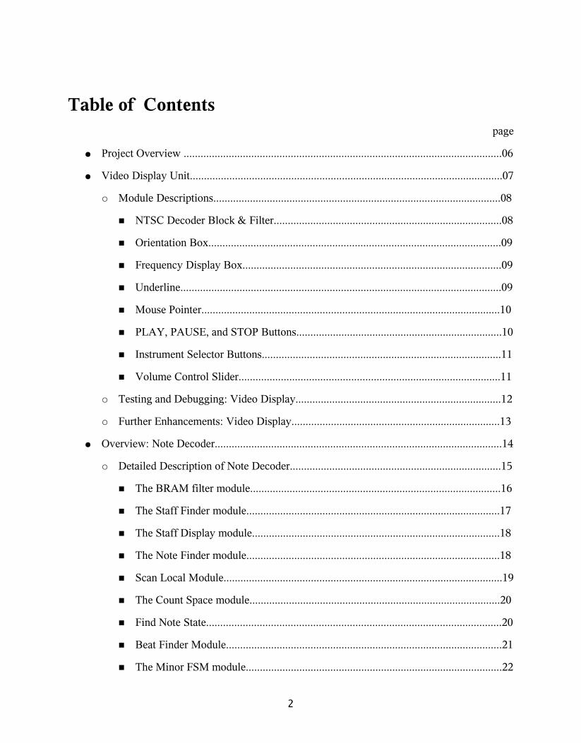
Table of Contentspage
● Project Overview .................................................................................................................06
● Video Display Unit...............................................................................................................07
○ Module Descriptions......................................................................................................08
■ NTSC Decoder Block & Filter.................................................................................08
■ Orientation Box........................................................................................................09
■ Frequency Display Box............................................................................................09
■ Underline..................................................................................................................09
■ Mouse Pointer..........................................................................................................10
■ PLAY, PAUSE, and STOP Buttons.........................................................................10
■ Instrument Selector Buttons.....................................................................................11
■ Volume Control Slider.............................................................................................11
○ Testing and Debugging: Video Display.........................................................................12
○ Further Enhancements: Video Display..........................................................................13
● Overview: Note Decoder......................................................................................................14
○ Detailed Description of Note Decoder...........................................................................15
■ The BRAM filter module.........................................................................................16
■ The Staff Finder module..........................................................................................17
■ The Staff Display module........................................................................................18
■ The Note Finder module..........................................................................................18
■ Scan Local Module...................................................................................................19
■ The Count Space module.........................................................................................20
■ Find Note State.........................................................................................................20
■ Beat Finder Module..................................................................................................21
■ The Minor FSM module...........................................................................................22
2

page
■ BRAM Decision module..........................................................................................22
■ Note BRAM module................................................................................................24
○ Testing & Debugging: Note Decoder.............................................................................25
○ Further Enhancements: Note Decoder...........................................................................27
● Audio Generator...................................................................................................................28
○ Overview and Background.............................................................................................29
■ Audio Synthesis........................................................................................................29
● AC97..................................................................................................................29
● Sine Wave Generation........................................................................................29
● Amplitude Modulation.......................................................................................30
○ Detailed Description: Audio Generator..........................................................................31
■ Audio Synthesizer....................................................................................................31
■ Tone Selector............................................................................................................31
■ Sine Wave Generation..............................................................................................31
● Tone Parameters.................................................................................................31
● Theta Memory....................................................................................................32
● Sine Calculator...................................................................................................32
■ Timbre......................................................................................................................32
● Timbre Transformer...........................................................................................32
● Instrument Generator..........................................................................................32
● Harmonic Parameters.........................................................................................33
● ADSR Parameters..............................................................................................33
● Note State RAM.................................................................................................33
● ADSR Scale Generator......................................................................................33
3

page
● Harmonic Scale Generator.................................................................................34
● Note Scaler.........................................................................................................34
■ Playback...................................................................................................................34
● Key Press Memory.............................................................................................34
● Sheet Player........................................................................................................34
● Event Player.......................................................................................................35
○ Testing and Debugging: Audio Generator.....................................................................35
○ Further Enhancements: Audio Generator.......................................................................38
● Integration of individual design components ......................................................................38
● Testing & debugging the overall system..............................................................................39
● Conclusion............................................................................................................................40
● References............................................................................................................................41
● Appendix..............................................................................................................................42
4
List of Figures: Page
Figure 1: System Block Diagram …………………………………………...……....….....06
Figure 2: Image of complete video display and note detection units…………………...…07
Figure 3: Image of the staff ………………………………………………………..……...08
Figure 4: Frequency display box………………………………………………………..…09
Figure 5: FSM showing state transitions for PLAY, PAUSE, and STOP………………...10
Figure 6: PLAY, PAUSE, and STOP buttons, & instrument selector buttons…………....11
Figure 7: Volume slider with mouse pointer…………………………………………...….12
Figure 8: Block Diagram of the Note Detection module……………………………….....15
Figure 9 : The BRAM filter process…………………………………………………….....16
Figure 10: The FSM of the Note Finder Module……………………………………….....18
Figure 11: The Staff Coordinates…………………………………………………….........19
Figure 12: The Count Space module………………………………………………...…….20
Figure 13: Noted on a staff…………………………………………………………...……21
Figure 14: Minor FSM………………………………………………………………….....22
Figure 15: The BRAM Decision FSM………………………………………………….....23
Figure 16: Final note information………………………………………………………....24
Figure 17: Audio Synthesizer Block Diagram………………………………………….....28
Figure 18: Integration signals displayed on the analyzer……………………………….....40
5

Project OverviewThe purpose of Phantom Sight Reader is to play sheet music as if it were playing from a
real instrument (piano, violin, flute, or cello). The project allows some simple sheet music to be printed out and played back. The user can play, pause or stop using the user interface in addition to selecting an instrument and changing the volume. The project is divided into three high level modules that control a particular area of functionality: Video Display and Filter, Note Decoder and Master FSM, and the Audio Synthesizer.
The Video Display allows for user input and outputs the note played to the user by underlining the note in the captured image and by showing it on a frequency chart. The Filter converts the image into a strictly black and white pixel format. This filtered format is taken in by the Note Decoder to recognize staffs and notes. The Master FSM orchestrates the process of decoding and enabling playback. The Audio Synthesizer contains all the logic for generating audio for the different instruments and playing back note data. The Block Diagram of the design project is given under figure 1 below.
Figure 1: System Block Diagram
Pixel
Camera
Video Display Unit & Filter (by
Jing)
Note Decoder & Integration
(by Dilini)
Audio Synthesizer (by Lance)
ZBT
AC97
Display
Pixel
Pixel
Pixel
ready
Sound_out
note_memory_
address
Play, Pause,stop, instrument_select
Marker,
note
noteaddr
6

Video Display Unit (by Jing Han)
The Video Display Unit provides an intuitive user interface. Functionalities include: a camera interface that displays the staff, including a grayscale-to-B&W filter that allows for easy detection of the staff and notes; the Orientation Box, which indicates to the user an optimal region in which to place the staff; the Underline, which will indicate on the staff which note is being played in real time; the Frequency Display Box, which displays the frequency of the note being played in real time; a mouse to allow user interaction; PLAY, PAUSE and STOP buttons, which allow the user to control the music being played; the Instrument Selector, which lets the user select which instrument to play; and the Volume Control Slider, which allows the user to adjust the volume.
Figure 2: Image of complete video display and note detection units.
7

Module Descriptions
NTSC Decoder Block & Filter
The NTSC decoder blocks consist of several modified pre-written modules [1]. The video_decoder.v file, which consists of the ntsc_decode module, the adv7185init module, and the i2c module, grabs 10-bit YCrCb data from camera. The ntsc2zbt.v file consists of the ntsc_to_zbt module, which stores 8 bits of Y (luminance) value, in grayscale to each ZBT location.
The filter is implemented by modifying the ntsc_to_zbt module (Figure 3). Its function is to convert the grayscale pixels output from ntsc_to_zbt into black and white pixels. A control switch, switch[5], turns the filter on or off. A user-adjustable threshold determines the value (between 0 and 256) at which a pixel is discriminated, i.e., if the threshold value is 170, pixels whose value is greater than 170 will be converted to black, and those less than or equal to 170 will be converted to white. A counter is created so that the threshold value increments or decrements every 1/10 of a second by pushing the up or down button on the labkit. An 8-bit Y value (now either all 0 or all 1) will then be sent to the display and also to the ZBT for further processing. The code that stores data to ZBT was borrowed from a sample module from Fall 2005 [2].
Since the data will be easier to process if the image is frozen, a switch (switch[6]) is implemented to freeze the data on the ZBT. This is done simply by stopping the write enable signal (ntsc_we) when switch[6] is on.
Figure 3: Image of the staff with two whole notes before filtering (left), and after filtering (right). Both images show the Orientation Box (thin black lines surrounding the staff), and the figure on
the right shows the Underline (thick black line under the first note).
8
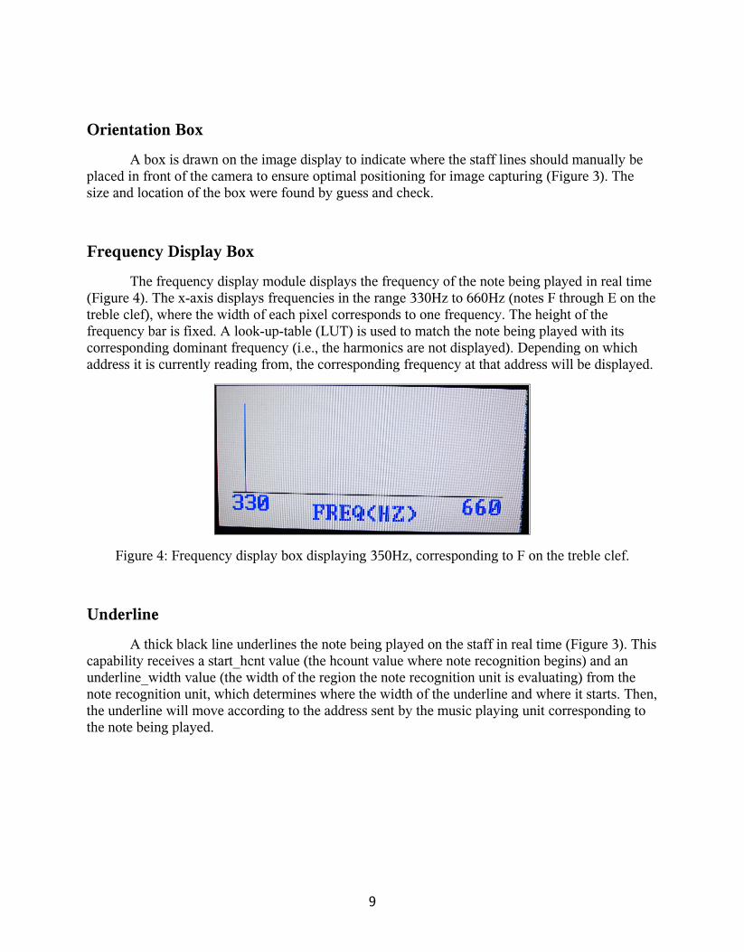
Orientation Box
A box is drawn on the image display to indicate where the staff lines should manually be placed in front of the camera to ensure optimal positioning for image capturing (Figure 3). The size and location of the box were found by guess and check.
Frequency Display Box
The frequency display module displays the frequency of the note being played in real time (Figure 4). The x-axis displays frequencies in the range 330Hz to 660Hz (notes F through E on the treble clef), where the width of each pixel corresponds to one frequency. The height of the frequency bar is fixed. A look-up-table (LUT) is used to match the note being played with its corresponding dominant frequency (i.e., the harmonics are not displayed). Depending on which address it is currently reading from, the corresponding frequency at that address will be displayed.
Figure 4: Frequency display box displaying 350Hz, corresponding to F on the treble clef.
Underline
A thick black line underlines the note being played on the staff in real time (Figure 3). This capability receives a start_hcnt value (the hcount value where note recognition begins) and an underline_width value (the width of the region the note recognition unit is evaluating) from the note recognition unit, which determines where the width of the underline and where it starts. Then, the underline will move according to the address sent by the music playing unit corresponding to the note being played.
9

Mouse Pointer
A mouse pointer is implemented as a small box sprite that allows the user to intuitively interact with the prototype [3].
PLAY, PAUSE, and STOP Buttons
Three buttons that enable the play, pause, and stop functionalities are implemented (Figure 6). Each is a one bit signal that controls the music player unit. The strings PLAY, PAUSE, and STOP are displayed within the regions allocated for the corresponding buttons using sample code from Fall 2005 [4]. The state is determined when the mouse is clicked in the region of the corresponding button. A simple finite state machine (FSM) is used to control the state transitions (Figure 5).
Figure 5: FSM showing state transitions for PLAY, PAUSE, and STOP.
STOP
play_signal=0
pause_signal=0
PLAY
play_signal=1
pause_signal=0
PAUSE
play_signal=0
pause_signal=1
(btn_click AND
stop_button_area) OR reset
(btn_click AND
stop_button_area)
btn_click AND
play_button_area
btn_click AND
pause_button_area
btn_click AND
play_button_area
10

Figure 6: PLAY, PAUSE, and STOP buttons, as well as instrument selector buttons.
Instrument Selector Buttons
Four buttons allow the user to select which instrument to play (Figure 6). The current prototype includes the piano, violin, cello and flute. The strings PIANO, VIOLIN, CELLO and FLUTE are displayed within the regions allocated for the corresponding buttons using sample code from Fall 2005 [4]. The desired instrument is selected when the mouse is clicked in the region of the corresponding button. The music player unit receives a 2-bit signal that indicates which instrument is selected.
Volume Control Slider
A volume slider allows the user to intuitively adjust the volume by dragging the slider up or down using the mouse (Figure 7). The slider bar is a sprite that changes location according to where the mouse drags it. A formula was used to convert the pixel values to the corresponding volume:
temp_value <= 736-top_of_slider;
volume <= temp_value [6:2];
Where temp_value is 8 bits wide (about the number of bits required to designate a vcount value), and volume is 5 bits wide. 736 is the vcount of the bottom (maximum vcount) of the slider box. Eliminating the last two bits of temp_value (by only taking [6:2] of temp_value)has the effect of dividing by four and rounding down, which eliminates the potential issue of non-integer results
11
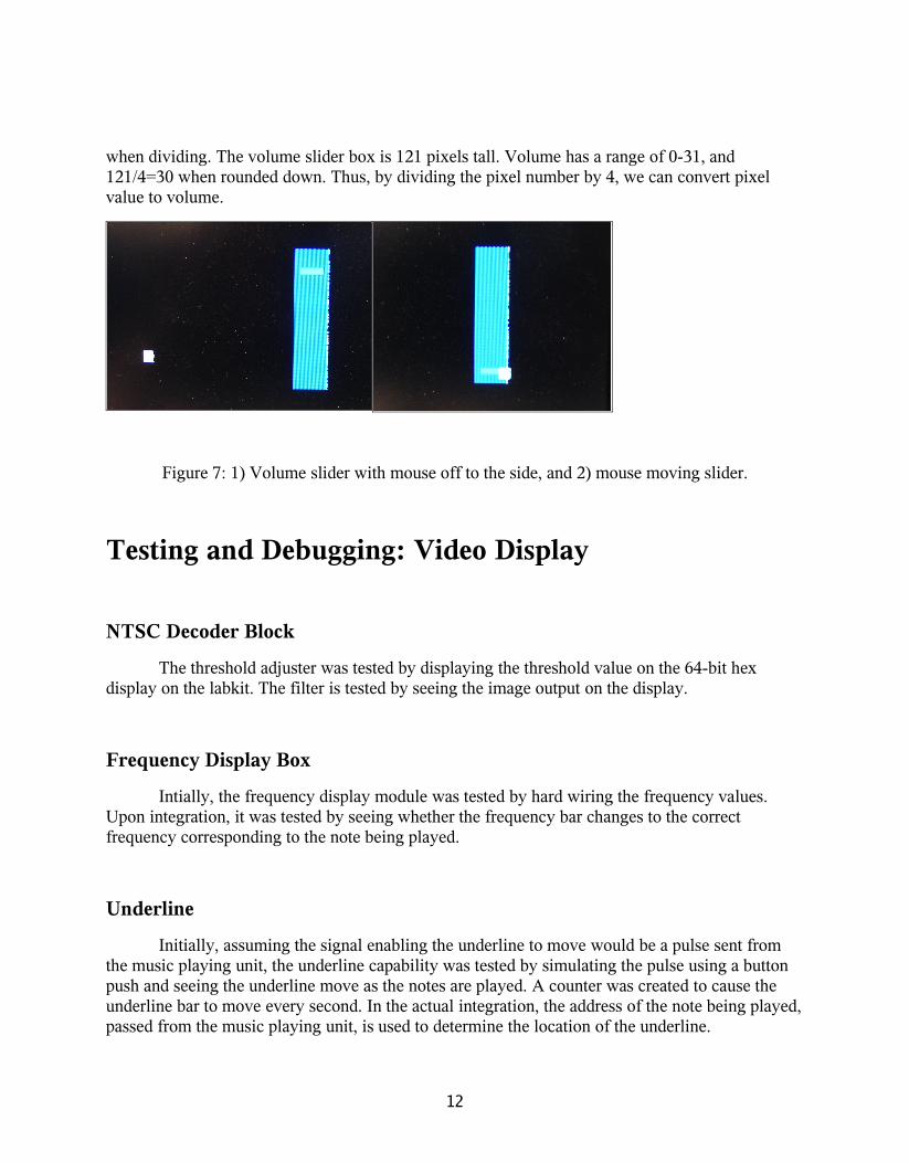
when dividing. The volume slider box is 121 pixels tall. Volume has a range of 0-31, and 121/4=30 when rounded down. Thus, by dividing the pixel number by 4, we can convert pixel value to volume.
Figure 7: 1) Volume slider with mouse off to the side, and 2) mouse moving slider.
Testing and Debugging: Video Display
NTSC Decoder Block
The threshold adjuster was tested by displaying the threshold value on the 64-bit hex display on the labkit. The filter is tested by seeing the image output on the display.
Frequency Display Box
Intially, the frequency display module was tested by hard wiring the frequency values. Upon integration, it was tested by seeing whether the frequency bar changes to the correct frequency corresponding to the note being played.
Underline
Initially, assuming the signal enabling the underline to move would be a pulse sent from the music playing unit, the underline capability was tested by simulating the pulse using a button push and seeing the underline move as the notes are played. A counter was created to cause the underline bar to move every second. In the actual integration, the address of the note being played, passed from the music playing unit, is used to determine the location of the underline.
12

Mouse Pointer
The cursor box representing the mouse is displayed on the monitor. The occurrence of a button click is indicated by the lighting of an LED.
PLAY, PAUSE, and STOP Buttons
The state of the FSM is displayed on the hex display, and the signals being sent are displayed on the LEDs.
Instrument Selector Buttons
To verify the correct instrument value was sent, the 2-bit signal value was displayed on the hex display.
Volume Control Slider
The unit was tested in two phases: first visually, then combining with audio. The volume slider must travel smoothly up and down as well as stop at the top and bottom of the slider box. Audio modules from Lab 4 [5] were used to test the volume control using a 750Hz tone.
Further Enhancements: Video DisplayThe frequency display box could be further developed into a frequency analyzer that
displays all the harmonic frequencies being played at any given time along with their corresponding amplitudes. In addition to its purpose of visual gratification, it can serve as a useful debug tool for the music player unit.
13

Overview: Note Decoder (Dilini Warnakulasuriyarachchi)
Once an image is captured by the NTSC camera and stored in the ZBT, the next step in the design project is to identify the notes on the music staff. This process is called Note Detection. In the Note Detection process there are three main sub categories: staff detection, note identification and the beat detection. Staff detection is important because before a note can be identified, we need to locate the staff on the captured image. Once we know the location of the staff we can narrow our analysis of the image to that particular region. We perform further analysis to identify the note. Then we will identify the beat of each note on the staff before data is sent to the audio generation module designed by Lance Collins. Each module under the staff detection, note detection and beat detection process is described in detail below. A block diagram of this part of the project is given under figure 8.
14

Figure 8: Block Diagram of the Note Detection module
Detailed Description of Note DecoderThe first module that is used to interact with the ZBT is the BRAM Filter Module. After
the data in the ZBT is filtered by this module the Note Decoder will no longer interact with the ZBT. It will access the BRAM where the filtered version of the image is stored. The Note Decoder contains Minor FSM module which controls the Staff Finder Module, the Note Finder Module and the Beat Finder module. Under the Staff Finder module the Staff Display module can be found. This module is used for debugging purposes. Under the Note Finder Module, the Count Space module and Scan Local module is utilized to evaluate the black pixels in the captured image. The Note BRAM Module and the BRAM Decision Module was created to ease the access of the BRAM. The following paragraphs contain a detailed description of each of these modules under the Note Decoder.
Minor FSM
Music Memory
Staff FinderNote FinderBeat Finder
enable_mfsm
Notes
staff_enablenote_enable
Note Decoder
BRAM Decision
BRAM Filter
beat_enable
BRAM
bram_mem_out bram_addr
filtered pixel
Pixel value
bram_mem_out / bram_addr
Master FSMZBT
15

The BRAM filter module
The image stored in the ZBT is the image captured from the NTSC camera. Therefore due to various lighting conditions and the quality of the camera, there can be various pixel errors in the image. To correct such pixel errors, a filter is required before the image is further processed. The ZBT stores data 8-bits per pixel. Once the image is filtered this 8-bit data will be converted to a 1-bit value which will take “1” if the pixel color is white or “0” if the pixel color is black. Since we only store 713 X 500 pixels, a Block Random Access Memory (BRAM) was used to store the filtered output. The memory was created using CoreGen and Architecture Wizard available in the Xlinx software package. It is a single port block memory with a width of 1-bit and a depth of 2^19. The logic behind the BRAM filter is explained below;
Two sets of errors can occur during image capturing. The first error occurs when there is a black pixel surrounded by a white space (white pixels). For example in a music sheet, space between two staff lines is white. However due to lighting conditions there can be few black pixels in this region. The second error occurs when there are white pixels in a region which should contain only black pixels. For instance a white pixel might occur on a staff line which must be black. To correct these two errors the BRAM filter was programmed in a manner that it allows a pixel color to change only if the two proceeding pixels are of the same color. This logic is able to correct the above errors even if two white/black pixels are situated next to each other in a region which should be black/white. The following image in Figure 9 will explain this program graphically.
Figure 9 : The BRAM filter process
As shown in the diagram above the first row of pixels contains two white pixels in a staff line. The filter will change these two white pixels into black pixels because the previous two pixels were black. As shown in the figure above the filter shift the original image to the right by two pixels since it only allows a pixel to change its color if the to proceeding pixels are of the same color.
Error
The incorrect pixel row
The filtered result
16

The Staff Finder module
The goal of this module is to identify where the staff is located on the captured image. The Staff Finder module will identify the horizontal pixel count (hcount) and the vertical pixel count (vcount) of the start of a staff and also the start of the second, third fourth and fifth staff lines. The program for this module performs this task by scanning the image row-wise and identifying a line when it encounters 150 continuous black pixels in a row. It identifies a white row when it encounters 150 white pixels continuously in a row. The program is explained in detail below:
There are several counters in the program. They are: 1) the line counter, which keeps track of the number of lines found, 2) the white pixel counter, which keeps track of the number of white pixels encountered in a row, and 3) the black pixel counter, which keeps track of the number of black pixels encountered in a row. Another important register is also used which is named the flag. The flag register keeps track of the beginning and end of a single staff line. This is required because the single staff line can be several pixels wide. The flag is raised when the first row of black pixels are encountered. Then the line counter is incremented by one. The program will disregard the next set of black rows it identifies until it encounters a white row. Then the flag is set to 0. The program continues to scan the image row-wise until it encounters the next black row. The flag is raised once again and the line counter is incremented by one. This recursive process continues until the line counter reaches the value 5.
The vcount and hcount of the start of each staff line are identified by noting the location of the first black pixel encountered in a row when all the proceeding pixels were white. The program identifies the first black pixels by checking whether the pixel color is black and if so it checks whether the black pixel counter is zero. If it is zero then it determines that the current pixel is the first black pixel in that particular row. However there still can be image errors even after filtering the image stored in the ZBT. To ensure that the black pixel the program encountered is not due to such an error, the vcount and hcount of the current pixel is noted in temporary registers. Once the line counter is incremented the data stored in the temporary registers are moved to permanent registers.
The Staff Finder module needs to interact with the BRAM to obtain the pixel values. Therefore this module will generate the BRAM address of each memory location as the image is scanned row-wise. The formula used to calculate the memory address is given below.
Bram_addr3 = (hcount – XSTART) + (vcount – YSTART) * XRANGE +
(vount – YSTART)
Formula 1
The image from the camera is displayed on the screen with resolution 1024 X 768. However the image is not displayed on the entire screen. It is limited to a window sized 713 X 500, starting at the pixel hcount 44 and vcount 64. The BRAM address however starts at 0 and increments by one. Therefore the above formula was generated to access the correct BRAM
17

memory location based on the pixel scanned by the module. Based on the coordinates of the widow used to display the image, the XSTART is set to 44 and YSTART is set to 64. The XRANGE is 713. The hcount and vcount is set to start at 64 and 84 respectively. This was done to scan the image 20 pixels inward from its edge to overcome and edge distortions that may have occurred when the image was capture. The BRAM address starts at 0 and continues up to 357,713.
The Staff Display module
This module was created to ensure that the Staff Finder module functions correctly. The inputs into this module are the hcount and vcount of the start and of the staff. The Staff Display module uses this information and displays on the screen the identified region. If the Staff Finder module provides the correct information the staff is displayed on the screen. The Staff Display module functions as follows;
The module checks if the current pixel hcount and vcount on the screen is within the start and end coordinates of the staff. If it is, the pixel value of the current pixel is obtained from the BRAM and sent to the display module. The BRAM memory address is calculated once again according to the formula 1 given above.
The Note Finder module
The Note Finder module’s goal is to identify the notes on a staff. This module functions as a Finite State Machine (FSM) with four states. The diagram of the FSM is shown below under figure 10.
Figure 10: The FSM of the Note Finder Module
As shown above in figure 10 , the FSM comprises of four states. At power on the initial state is the INACTIVE state. Once the note_enable signal is set to “1” the state transitions to the
Inactive State
Local Scan State
Scan Space State
Find Note State
note_enable
local_scan_done
cnt_done
cnt_note == 0cnt_note = 0
Find Note State
18

LOCAL SCAN state. This state enables the Scan Local module which identifies where the staff lines are situated local to the notes. Once the local_scan_done signal is enabled the state transitions to the SCAN SPACE state. This state will count the number of black pixels in the four spaces where a note is located. Once the cnt_done signal is enabled by this module the next transition is to FIND NOTE state. The FIND NOTE state will compare the number of black pixels in each space and identify the note. Once this state is reached, the Note Finder module checks whether the cnt_note counter, which contains the number of notes in a single staff is zero. If it is zero then the next state transition is to the INACTIVE state. If the cnt_note counter is not zero, it means there are other notes to be located. Therefore the next state transition is to the LOCAL SCAN state. Each sub module under the Note Finder is explained in the subsequent sections. .
Scan Local Module
This module’s goal is to identify where the staff lines are located local to the notes. This module is slightly similar to the Staff Finder module. However, it is an important module. If we observe the image captured from the NTSC camera, we can notice that the staff lines tend to curve due to the circular nature of the camera lens. Therefore even though the Staff Finder module locates the hcount and the vcount of the start of the staff lines, towards the middle and end of the staff these coordinates may vary. To overcome this problem, the Scan Local module is introduced to identify the staff lines local to the notes based on the information given by the Staff Finder module. The logic behind this module is as follows.
The Scan Local module expects the start and the end hcount values of the region where a note will be located. For instance if there are only two notes on a staff the entire window will be split into two halves and each individual half is evaluated separately. This module will start to scan the pixel colors in a vertical line starting at 10 pixels above the vcount of the start of the staff, identified by the Staff Finder module. If the pixel color is black and a “flag” is zero the line counter is incremented by one and the vcount is noted. This vcount denotes the start of a staff line. If the pixel color is white and the “flag” is set to 1 then this vcount is noted since it will be the end of the staff line. According to this program each staff line will have two vcount values associated to it. The exaggerated diagram of a staff given below under figure 11 further explains this process. The output of this module will be 10 vcount values associated with the five staff lines.
Figure 11: The Staff Coordinates
vcount of the
start of the line
19
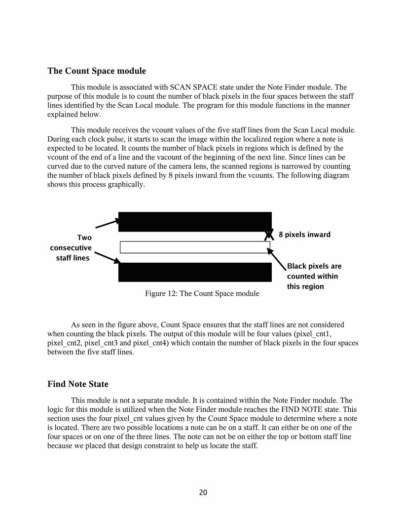
The Count Space module
This module is associated with SCAN SPACE state under the Note Finder module. The purpose of this module is to count the number of black pixels in the four spaces between the staff lines identified by the Scan Local module. The program for this module functions in the manner explained below.
This module receives the vcount values of the five staff lines from the Scan Local module. During each clock pulse, it starts to scan the image within the localized region where a note is expected to be located. It counts the number of black pixels in regions which is defined by the vcount of the end of a line and the vacount of the beginning of the next line. Since lines can be curved due to the curved nature of the camera lens, the scanned regions is narrowed by counting the number of black pixels defined by 8 pixels inward from the vcounts. The following diagram shows this process graphically.
Figure 12: The Count Space module
As seen in the figure above, Count Space ensures that the staff lines are not considered when counting the black pixels. The output of this module will be four values (pixel_cnt1, pixel_cnt2, pixel_cnt3 and pixel_cnt4) which contain the number of black pixels in the four spaces between the five staff lines.
Find Note State
This module is not a separate module. It is contained within the Note Finder module. The logic for this module is utilized when the Note Finder module reaches the FIND NOTE state. This section uses the four pixel_cnt values given by the Count Space module to determine where a note is located. There are two possible locations a note can be on a staff. It can either be on one of the four spaces or on one of the three lines. The note can not be on either the top or bottom staff line because we placed that design constraint to help us locate the staff.
Two consecutive
staff lines
8 pixels inward
Black pixels are counted within this region
20

If a note is located on a space then the pixel_cnt relating to that space will have number of black pixels and the other pixel_cnts will contain zero values. If a note is located on a line, the two spaces upon which the note is on will have black pixel counts, and other spaces will contain zero black pixels. To identify the note, the spaces are evaluated as given below.
If the first space contains the maximum number of black pixels compared to the other three spaces, the note is on that space or on the line at the end of that space. Therefore, the number of black pixels on the first space is compared with the number of black pixels on the second space. If the number of black pixels in the first space is greater that number of black pixels in the second space plus a threshold value, then the program decides that the note is on the space instead of the line. The note is noted as “E”. However, if the number of black pixels on the first space does not exceed this combined value (number of black pixels in second space plus a threshold value), the note is considered to be on the line. Then the note is noted as “D”. This same process is repeated based on the space with the maximum number of black pixels. The threshold value was determined by trial and error process.
Beat Finder Module
The Beat Finder module determines the duration of a note. A note can be a whole note, a half note or a quarter note. Once the Note Finder module was fully functional the Beat Finder module was easy to implement. This module uses the black pixels counts of the fours spaces and adds them together. Then it evaluates whether the total number of black pixels are less than 200. If they are less than 200 then the beat was defined as a whole note. If the number of black pixels are between 200 and 250 the beat was defined as a half note. If the number of black pixels exceeded 250, the note was defined as a quarter note. The reasoning for this process is explained by the diagram in figure 13.
Figure 13: Noted on a staff
As seen in the figure above the whole note (semibreve) will have the minimum number of black pixels compared to the Minim and Crochet. Generally, the number of black pixels, when the
Semibreve Minim Crotchet
21

note is a whole note was below 200. The Minim will have the second highest black pixels. The Crotchet will have the maximum number of black pixels.
The Minor FSM module
The Minor FSM module integrates the Staff Finder module, the Note Finder module and the Beat Finder module. This FSM is comprised of four states: STAFF, NOTE, BEAT, INACTIVE. The state machine is shown in the following figure 14.
Figure 14: Minor FSM
As seen in the above diagram, the power on state is the INACTIVE state. Once the enable_mfsm is set to “1” by the Major FSM, the state transitions to the STAFF state. This state enables the Staff Finder module. Once the Staff finder module locates the staff on the image, it sends a staff_done signal to the Minor FSM module. Then the next transition is to the NOTE state. This state enables the Note Finder module. When a note_done signal is received from the Note Finder module the Minor FSM module transitions to the BEAT state and enables the Beat Finder module. Once the beat_done signal is received from the Beat Finder module the Minor FSM sends a mfsm_done signal to the Major FSM.
BRAM Decision module
The BRAM memory is accessed several times by modules such as the Staff Finder module, the Scan Local module, and the Count Space module under the Note Finder module. Therefore, it is important to ensure that correct memory locations are accessed in these modules. The BRAM Decision module was created for this purpose. This module is also activated as a finite state
Beat State
Note State
enable_mfsInactive
State
staff_done
note_done
beat_done
Staff State
22

machine with 6 states: DATA_WRITE, DISPLAY_BRAM, TO_STAFF, DISPLAY_STAFF, L_SCAN, and SPACE.
The power-on state is the DATA_WRITE state. This state ensures that data stored in the ZBT are filtered via the BRAM Filter module and written into the BRAM. This is the only state where data is written into the BRAM. In all other states data is read from the BRAM. Once the state machine leaves the DATA_WRITE state it never returns to this state unless the reset button is pressed.
From the DATA_WRITE state there are two possible state transitions: DISPLAY_BRAM or the TO_STAFF state. DISPLAY_BRAM was introduced as a debugging state to ensure the filtering was done correctly. TO_STAFF state interacts with the Staff Finder module to locate the staff on the image. Once the staff_done signal is enabled, the BRAM Decision module can transition to the DSIPLAY_STAFF or the L_SCAN state. DISPLAY_STAFF state is another debugging state which accesses the BRAM and displays on the screen the region where the staff was identified by the Staff Finder module.
The L_SCAN state interacts with the Scan Local module to locate the staff lines local to a note. Once the local_scan_done signal is enabled the next state transition is the SPACE state. This state interacts with the Count Space module to count the number of black pixels in each space. The FSM is displayed under figure 15.
WRITE_DATA
DISPLAY
_BRAM
TO_
STAFF
SPACE
L_SCANDISPLAY_STAFF
sw_test = 1
staff_enable staff_enable
staff_done &
enable_local
enable_local_scan
sw_test=2local_scan
_done
sw_test = 1
23

Figure 15: The BRAM Decision FSM
Note BRAM module
This module was created to store the final note information in order to be accessed by the Audio unit. A BRAM was created to store the note information. The inputs into this module is the 16-bit note information provided by the Note Finder module and the 16-bit beat information provided by the Beat Finder module. Once the enable_note_bram is set to “1” by the Major FSM, the Note BRAM module is activated. A counter is used in this module to keep track of the number of notes. For instance if a staff contains four notes, the counter is set to four at the beginning. Once this module is enabled, the 16-bit note information and the 16-bit beat information is and together to produce a 16-bit note. The format of this 16-bit note is shown under figure 16.
From the
Note Finder
Module
From the
Beat Finder
Module
Final Note
Figure 16: Final note information
As seen in the figure above, the Note Finder module produces a 16-bit data for each note on the staff. According to the figure above, the note identified by the module is an “A”. The Beat Finder module produces another 16-bit data that defines whether the note is a whole note, half note or a quarter note. The key used to differentiate the three beats is as follows:
Whole note:
0 0 0 0 0 0 0 0 0 0 1 1 0 0 0 0
- E D C B A G F
0 0 0 0 0 0 0 0 0 0 0 1 0 0 0 0
0 0 0 0 0 0 0 0 0 0 0 1 0 0 0 0
- E D C B A G F
24
1 1 1 1 1 1 1 1 1 1 1 1 1 1 1 1
Half note:
1 0 1 0 1 0 1 0 1 0 1 0 1 0 1 0
Quarter note:
0 1 0 1 0 1 0 1 0 1 0 1 0 1 0 1
Therefore in the figure **** the note “A” is a quarter note. The Final Note in the figure **** is the result the program obtained by performing the AND function between the note information and the beat information. This will be stored in the BRAM to be accessed by the Audio module. The most significant bit (MSB) and the bit before the MSB are used to indicate the final note in the staff. For instance, if the staff contains four notes, the MSB and the one before the MSB is set o “1” in the fourth note before it is stored in the BRAM.
Testing & Debugging: Note DecoderTesting and debugging of the Note Decoder section is very important to ensure that correct
notes are passed into the audio module before it is played. Most of the testing and debugging for the modules under the Note Decoder section of this project was done using the hexadecimal display on the labkit and the logic analyzer. At times the data was also displayed on the computer monitor to visually verify the outputs. The testing & debugging of each module is described in detail in the subsequent paragraphs.
The BRAM Filter module
As explained under the BRAM Filter module this program attempts to correct pixel errors that may occur due to the lighting on the image and the camera quality. This module was debugged by displaying the filtered image on the computer monitor and comparing it with the original image stored in the ZBT. A much cleaner image was displayed on the screen as a result of this filtering.
25

The Staff Finder module
The Staff Finder module identifies where the staff is located on the sheet of paper scanned by the camera. Two methods were used to test this module. The first method was to display the start hcount and vcount of the staff as well as the number of lines recognized by this module on the hexadecimal display on the labkit where the project was prototyped.
The second method that was used to debug this module was to display the identified region on a screen by using the Staff Display module. If the Staff Finder module functions correctly, the staff is displayed on the screen.
The Scan Local module
The Scan Local module was tested by displaying the identified vcounts of the lines on the hexadecimal display. Then these values were compared with the values found by the Staff Finder module. If the lines identified by the Scan Local module lie within the region identified by the Staff Finder module, it was decided that the Scan Local module functions as expected.
The Count Space module
The Count Space module was debugged by observing the pixels counts of each space on the hex display and also analyzing the vcount and hcount on the logic analyzer. For instance if the note is located on a space then pixel count for that space will contain some value and all the other pixel counts will be zero.
The Note Finder module
The Scan Local module and the Count Space module fall under the Note Finder module. Therefore, when the Scan Local module and Count Space modules were tested the Note Finder module was also partially tested. The section that was not tested was determining the note. Therefore the output of this module which is the note was displayed on the hexadecimal display to test the accuracy of this decision making.
The Beat Finder module
The Beat Finder module determines the beat of the identified module. It was convenient to test this module by simply displaying the identified beat on the hexadecimal display.
26

The Note BRAM module
The Note BRAM module was used to store the final notes in a BRAM to be accessed by the Audio module. This module was also tested by displaying the address of the BRAM and the data from the BRAM on the hexadecimal display.
The Minor FSM
As described in the previous pages the Minor FSM integrates the Staff Finder module, the Note Finder module and the Beat Finder module. Therefore this module was tested by ensuring that all the three sub modules function as expected after being integrated together.
Further Enhancements: Note DecoderDue to the time constraints, the Note Decoder section of this design project was
successfully implemented to identify two whole notes on a single staff. However this functionality can be further improved to identify the half notes and the quarter notes and also to identify multiple staffs as well as multiple notes.
The current Minor FSM assumes that there is only a single staff on the scanned sheet. Therefore after it receives a beat_done signal from the Beat Finder module it remains in INACTIVE state without activating the STAFF state once again. By changing the Minor FSM to run the current process repeatedly according to the number of staffs on a sheet (re-enable the Staff Finder module), multiple staff recognition is possible.
Identifying the half notes and the quarter notes can be performed by changing the Note Finder module. After the pixel counts of each space is provided, the threshold values for determining whether it is F, G, A, B,C, D or an E needs to be adjusted to accommodate the range of black pixels that are counted for a half note and a quarter note. Furthermore, the Beat Finder module can be changed to recognize whether it is a half note or a quarter note by changing it threshold values as well.
Identifying multiple notes is slightly difficult due the quality of the camera. To have multiple notes on a single staff, the staff lines need to be long. This increases degree of curving of these lines due to the camera’s circular lens. To overcome this problem the Scan Local module and the Count Space module needs to be more robust and more flexible as it progresses along the staff.
27
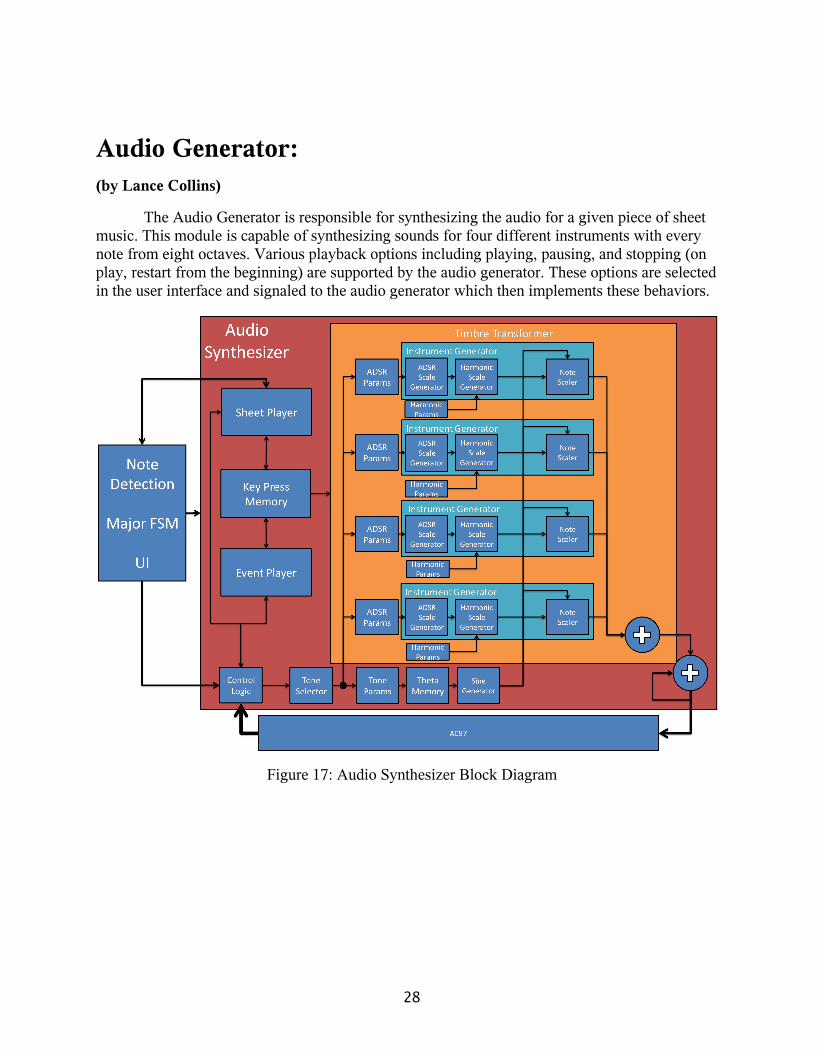
Audio Generator:(by Lance Collins)
The Audio Generator is responsible for synthesizing the audio for a given piece of sheet music. This module is capable of synthesizing sounds for four different instruments with every note from eight octaves. Various playback options including playing, pausing, and stopping (on play, restart from the beginning) are supported by the audio generator. These options are selected in the user interface and signaled to the audio generator which then implements these behaviors.
Figure 17: Audio Synthesizer Block Diagram
28
Overview and BackgroundThe Audio Generator functionality can be divided into two discrete areas: playback and
audio synthesis. Playback entails transforming the input to the Audio Generator into key press events that can be used to synthesize the audio.
Audio Synthesis:
Audio output is synthesized by combining sine waves to form the desired sound. For a given instrument, a note is composed of many different sinusoids known as harmonics. The frequency of each harmonic is an integer multiple of what is known as the first harmonic or fundamental. Each instrument has particular characteristics of their sound known as the timbre. The timbre is what allows us to distinguish between a violin and a piano. One factor that constitutes an instrument’s timbre is the relative amplitudes for each harmonic. The timbre for each instrument is also determined by the variance of the amplitude over time as a particular note is pressed or released. In general, the variance of the amplitude for an instrument is very complex, but it is often simplified into a model known as the ADSR (Attack Decay Sustain Release) envelope which is explained in section 3.1.1.3.
1. AC97
The AC97 transforms the binary audio data into an audio signal output to the headphone jack. It generates 48000 ready pulses per second. The ready pulse tells the Audio Synthesizer that the AC97 is ready to receive new audio data. Given that the Audio Synthesizer runs on a 27Mhz clock, the Audio Synthesizer has ~562 clock cycles to perform computations. Most of the code for interfacing with the AC97 was taken from the Lab 4[5]. It was modified to use the volume information from the UI Volume Slider and to take 18-bit values instead of 8-bit values.
2. Sine Wave Generation
The sine wave calculator takes in a 16-bit signed value, THETA, where
Formula 2
For a given sine wave of frequency, F,
. Formula 3
The AC97 takes in 48,000 samples per second. For sample, s,
29

. Formula 4
Therefore, θ is now defined as
. Formula 5
Using the pre-computed θinitial and ∆θ values, the input, THETA, of the sine function is determined (the effect of different θinitial values did not vary significantly between instruments, so the same θinitial values were used for all instruments. So, if the desired frequency is 261.626 Hz (Middle C), the ∆θ can be calculated as follows:
Formula 6
3. Amplitude Modulation
Amplitude modulation happens in two places in the Audio Synthesizer. Scaling the harmonics to their relative amplitudes Application of the ADSR Envelope (amplitude variance over time)
To modulate the amplitude, a utility module called the Scaler is used. The Scaler uses a “scale factor” to adjust incoming data. In an abstract since, the scale factor is a value between 0 and 1, which can adjust the amplitude at discrete values between its initial amplitude and zero. The scale factor is a positive 8-bit integer, which has valid values between 0000_00002 (0) and 1000_00002 (128). For values above 1000_00002 (128), the lower order bits are ignored and the scale factor is considered to be 1000_00002 (128). The Scaler multiplies by the scale factor, then divides by 128 (shift right by 7-bits).
For example, a scale factor of 128 means the data remains unchanged, but a scale factor of 64 means the data is divided by 2. The scale factors for the harmonic amplitudes are constant, so they are retrieved from a lookup. However, the ADSR Envelope varies with time, so the value must be computed.
The ADSR Envelope is divided into four states: attack, decay, sustain, and release. The attack begins after the note is struck, and is immediately followed by the decay and sustain. When the note is released, the release phase begins. During the attack phase, the amplitude increases to its maximum value. Then, during the decay phase, the amplitude decays to a more moderate level. It remains in this range during the sustain phase, and eventually zeroes out during the release phase. The audio synthesizer maintains state information for each note about its position in the ADSR envelope function and updates this based on the time elapsed and key press signals received from the playback modules.
30

The ADSR Envelope is divided into samples (256 samples per second). The attack and decay stages have a certain duration defined in terms of number of samples elapsed. Each stage has a delta value, which specifies how much the amplitude changes per sample. However, there are 187 ready pulses per sample so amplitude must change at more discrete values than those specified by the ADSR parameters. To accomplish this, there are fractional bits attached to the scale factor used for ADSR modulation. This equivocates to interpolating between samples where the factor (scale factor + fractional bits) takes on distinct values between samples.
Detailed Description: Audio Generator
Audio Synthesizer
The Audio Synthesizer is the main module which manages all audio generation. It coordinates a six stage pipeline with multiple working parallel during each stage. It has some simple control logic which interprets play, pause, and stop signals from the UI module. When playing, this module enables the Tone Selector, the beginning of the pipeline, which cascades enable signals through the pipeline. Ultimately, the final audio data is generated and on the next ready pulse, it is output to the AC97 and the process begins again. The control logic also selects between two player modules: the Event Player and the Sheet Player. The enabled player’s key press data is stored into the key press memory and read later.
Tone Selector
The Tone Selector begins upon receipt of an enable signal. It sends tone indices (octave, note, and harmonic) through the pipeline on each clock cycle and each successive module computes based on these values and the outputs of the prior modules. The Tone Selector is comprised of a cascade of counters which overflow to the next counter when they reach their maximum value. The counters iterate through the octave, note, and harmonic indices, respectively. When all indices have been output, the module stops until another enable signal is received.
Sine Wave Generation
1. Tone Parameters
The Tone Parameters module takes the tone index information and outputs the corresponding initial theta and delta theta values on the next clock cycle. The delta theta for the fundamental harmonic of the highest octave can be used to calculate the delta theta for all harmonics of all octaves of that note using simple addition and multiplication.
31

2. Theta Memory
The Theta Memory operates in two stages. First, it retrieves last theta value for the input tone and increments it by the theta delta output from the Tone Parameters module. Second, this incremented theta value is output and stored as the new theta value for that tone. The Theta Memory contains a two-port RAM so that it can operate each stage (retrieving and storing) concurrently. While the input tone’s theta is retrieved, the incremented theta for the last input tone is stored and output.
3. Sine Calculator
The Sine Calculator is comprised of 15 BRAMs which store the sine output for 16-bit theta values. This module was generated using the Coregen tools provided with Xilinx. There is a delay of one clock cycle between the input of a theta value and the output of corresponding sine value.
Timbre
1. Timbre Transformer
The Timbre Transformer manages all transformations to the sine data coming from the Sine Calculator, to apply the timbre of the instruments. For each instrument, it has Instrument Generator, and ADSR Parameters, and Harmonic Parameters modules which the Timbre Transformer wires together so that they apply the correct modulation to the sine data. Like the Audio Synthesizer, it is divided into pipeline stage's and where each stage is dependent on the prior stage’s input. Each stage corresponds to a stage in the audio synthesizer, so it is easy to hook the inputs from the Audio Generator into specific stages. The output of the Instrument Generators is added together and output to the Audio Synthesizer.
2. Instrument Generator
The Instrument Generator coordinates the transformation of the outputs of the Sine Calculator, ADSR parameters, and Harmonic Parameters modules into the correct tone output for the instrument. This module is designed to be generic so that attaching the correct Harmonic and ADSR Parameters modules will yield the correct output. This module is organized into a pipeline that works alongside the pipelines for the Timbre Transformer and Audio Synthesizer so that signals arrive at the correct timing.
32

3. Harmonic Parameters
A unique version of this module is specified for each instrument. This module is a lookup table which outputs the relative amplitude of each harmonic as a scale factor (as described in the Amplitude Modulation section). The module takes the harmonic index as input and outputs on the next clock cycle. See the appendix for a table of the values corresponding to each instrument.
4. ADSR Parameters
Similar to the Harmonic Parameters module, this module is distinct for every instrument. In the simplest case, this module outputs constant delta values which indicate the change in the amplitude per sample for each state (attack, decay, sustain, and release) along with the duration of the attack and decay states. This means the amplitude changes linearly when in a particular state. Since the change in amplitude for the violin and cello is nonlinear for the sustain state, the corresponding ADSR Parameters module reflects this by outputting delta values consistent with those of a sinusoid.
5. Note State RAM
Inside each Instrument Generator module, the ADSR information of each note must be stored. This module stores this state information in RAM. The state information consists of:
ADSR State – Attack, Decay, Sustain, or Release
ADSR count – the number of samples that have elapsed since the state began. Used to end a state when its duration is over.
ADSR Factor – a combined value represented the scale factor and fractional bits which allow the scale factor to be incremented with higher granularity.
To minimize the latency, reads and writes are performed concurrently using a two port RAM. The state information is updated by the ADSR module and stored on the next clock cycle while new state information is retrieved and output.
6. ADSR Scale Generator
The ADSR Scale Generator takes in the ADSR parameters, the current state information of the note, and the key press status, and updates and stores the next state in the Note State RAM. This update process can be separated into stages:
1. Determine the next ADSR state based on key press information and current ADSR state from the Note State RAM.
33

2. Get the delta value for the current ADSR state.
3. Calculate the new factor value for the next state (interpolation).
4. Update sample count (goes to zero if state changes, otherwise it increments)
7. Harmonic Scale Generator
The Harmonic Scale Generator is just a modified Scaler module which is designed to take two unsigned integer values (the harmonic scale factor and the ADSR scale factor). It outputs an adjusted scale factor for the harmonic based on the ADSR scale factor.
8. Note Scaler
This is a Scaler module which uses the adjusted scale factor from the Harmonic Scale Generator to modulate the amplitude of its incoming data from the Sine Generator. This is the final module before the information is output to the Timbre Transformer.
Playback
1. Key Press Memory
The Key Press Memory stores the key press information for each instrument. Each line in the RAM stores 4 bits, the key press for each instrument for the note corresponding to that address. This is done because each Instrument Generator acts concurrently, their key press information needs to be extracted simultaneously. When an instrument’s key press information is updated, the key press information for other instruments must remain unchanged. So when it receives an instruction to write key information, it reads the address, updates the bit corresponding to the instrument, and stores it back in the RAM. To prevent conflicts, it does not allow reads to happen concurrently with writes. There is a writable signal that is output to the player modules so they are only enabled when the Key Press Memory is writable.
2. Sheet Player
The Sheet Player takes the information from the Note RAM in the Note Detection module and outputs key press events. The next note is pre-fetched from the Note RAM because the latency introduced by connecting two FPGAs. It plays each note in succession and maintains a state for each note corresponding to the number of remaining beats that the note should remain playing. Each beat, it decreases these remaining beats and finally shuts off the note when it has no beats remaining.
34
State Index Note State0 NONE1 QUARTER NOTE2 HALF NOTE4 WHOLE NOTE
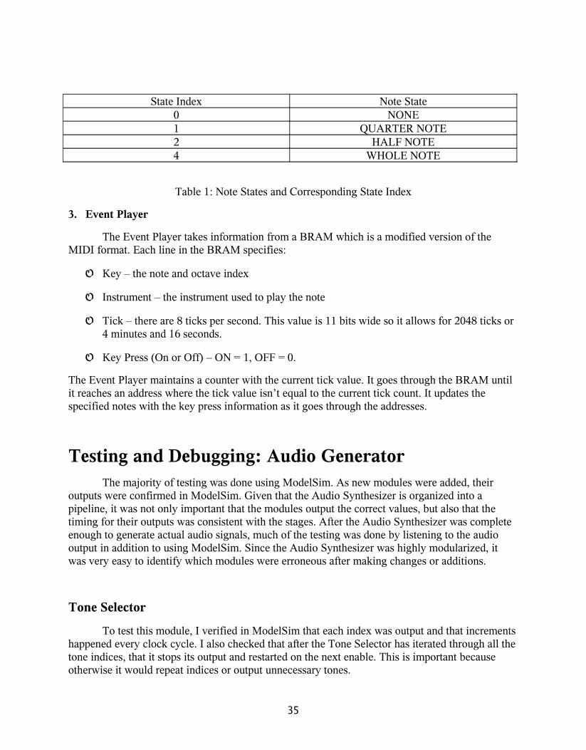
Table 1: Note States and Corresponding State Index
3. Event Player
The Event Player takes information from a BRAM which is a modified version of the MIDI format. Each line in the BRAM specifies:
Key – the note and octave index
Instrument – the instrument used to play the note
Tick – there are 8 ticks per second. This value is 11 bits wide so it allows for 2048 ticks or 4 minutes and 16 seconds.
Key Press (On or Off) – ON = 1, OFF = 0.
The Event Player maintains a counter with the current tick value. It goes through the BRAM until it reaches an address where the tick value isn’t equal to the current tick count. It updates the specified notes with the key press information as it goes through the addresses.
Testing and Debugging: Audio GeneratorThe majority of testing was done using ModelSim. As new modules were added, their
outputs were confirmed in ModelSim. Given that the Audio Synthesizer is organized into a pipeline, it was not only important that the modules output the correct values, but also that the timing for their outputs was consistent with the stages. After the Audio Synthesizer was complete enough to generate actual audio signals, much of the testing was done by listening to the audio output in addition to using ModelSim. Since the Audio Synthesizer was highly modularized, it was very easy to identify which modules were erroneous after making changes or additions.
Tone Selector
To test this module, I verified in ModelSim that each index was output and that increments happened every clock cycle. I also checked that after the Tone Selector has iterated through all the tone indices, that it stops its output and restarted on the next enable. This is important because otherwise it would repeat indices or output unnecessary tones.
35
Tone Parameters
Using ModelSim, the output (the value of initial theta and delta theta) for corresponding tone index information was verified by checking the values of these buses one clock cycle after receiving a tone index.
Theta Memory
The internal RAM used in the module was observed to ensure that the memory was updated properly and that the incremented theta output was correct. Since the delta theta value had to be delayed to line up with the output of the last theta from the BRAM, this timing was verified.
Sine Calculator
For this module, I checked what sine values were generated for given values of theta. There was a text file which specified the contents of the BRAM. I looked up the corresponding theta address and ensured that the sine data matched with the observed value from ModelSim.
Timbre Transformer
The Timbre Transformer was primarily tested by listening to the audio output. The pipeline portion was tested by checking the cascade of enable signals and tone indices lined up with values from the Audio Synthesizer.
ADSR Scale Generator
The bulk of the testing of the Instrument Generator was devoted to testing the ADSR Scale Generator. The interpolation portion was the most complex part of this module. I manually calculated the expected values and verified the output using ModelSim.
Harmonic Scale Generator and Note Scalar
These modules were comprised of Scaler modules. These modules were tested in isolation in ModelSim by inputting test data and checking the output against manually calculated desired values. When the modules were integrated into the Audio Synthesizer, the generated scales were output to the hex display for a particular tone. While these values changed very quickly, a rough idea of the scale could be seen.
36

Key Press Memory
The main difficulty with the Key Press Memory was ensuring that it output its writable signal at the correct time and that code for changing a single bit was correct. Using the Player modules to input test data, I checked that the lines of the internal RAM were updated correctly with only the desired bit modified.
Sheet Player
To test this module, I used a simple module with the notes for “Mary Had A Little Lamb” and viewed its outputs in simulation in addition to listening to the audio output. The RAM address was output to the hex display to see that it was updated correctly.
Event Player
The Event Player was tested using transformed MIDI data from a midi file for “Rose” from the movie Titanic. The tick count and the current BRAM address were output to the hex display to ensure that they were incremented corrected.
Audio Synthesizer
This module was the main module, so function was dependent on its submodules. However, there were parts that were contained only within this module that required testing. The main part that was specific to this module was the control logic. I ensured that it only output new sound data when the play signal was received and that it reset when the stop signal was received. Also, the proper progression of the enable signals and the tone index information through the pipeline was verified.
To listen to the audio output, the switches on the FPGA were latched to key press events. By activating these switches, I was able to hear the output for particular notes. Also, using the Player modules allowed me to see the Audio Synthesizer under more complex circumstances, where the input changes rapidly.
37
Further Enhancements: Audio GeneratorSome further enhancements would be sound effects such as reverberation and increasing
the accuracy of the sound compared to the sound of the actual instrument. Another potential enhancement would be to add more instruments, which could be easily done by adding new instrument generator modules with different attached ADSR Parameters and Harmonic Parameters modules.
Integration of individual design components As mentioned in the overview, this design project comprises of three main components:
The image capture, note recognition and audio generation. These three sections were individually designed, programmed and tested by three engineers. Therefore it was imperative to have an efficient integration plan when the individual components were brought together to implement the overall project. The first step of the integration was to combine the image capture and display features created by Jing Han with the note decoder section create by Dilini Warnakulasuriyarachchi. Once this was successful the second step was to integrate the audio generation module created by Lance Collins.
The image capture module and the note recognition module were integrated by first introducing the mouse pointer module with the note recognition module. Then the next step was to introduce the code for the display of the volume control slider into the note recognition code. The third step was to introduce the code for the display of Play, Pause, Stop buttons and the Frequency Display box into the note recognition code. This step by step method reduced the complexity of the integration process and made debugging an easy task. The image capture module and the note recognition module were successfully integrated.
The first attempt of integrating the audio generation code into the image recognition and note recognition code was not successful. During integration various routing issues arose reducing the audio quality. Therefore to overcome these problem two labkits were utilized. One labkit contained the audio generation module and the other labkit contained the image capture and the note recognition module. The two labkits were connected by wires. To reduce the number of wires used to connect the labkits, the wires were used as a serial line by using shift registers to send and receive data. The process is explained in detail below.
From the note recognition module 17 bits of data is sent to the audio generation module: 16 –bits for the note and 1 bit as the enable_audio signal. If the shift register method was not used it would require 17 wires to connect the audio generation with the note recognition module. This method is not practical since having too many external wires can corrupt the signal due to interference among the wires. Therefore the shift register principle was used. From the image capture and the note recognition module 27 bits of information is sent to the audio generation module. From the audio generation module 5 bits of information is sent to the image capture and note recognition module.
38

Output from Audio:
{ audio_done [1 bit], beat_delay [1 bit], bram_addr [3 bit]}
Output from the Image capture & Note recognition:
{audio_enable [1 bit], volume [5 bits], play [1 bit], pause [1 bit], stop [1 bit], instrument_select [2 bits], note [16 bits]}
There is a single wire as output from the audio module and another single wire as the output from the image capture and note recognition module. Another wire was used to send a common clock signal to receive and send data. Two other wires were used to notify each labkit that data is ready to be read. In total 5 wires were used to establish the communication between the two labkits.
As mentioned before, the serial wire transmission was established by using registers. At the audio generation end, a register is created to hold the 5 bits output data. During each clock signal one bit of information is sent via the wire. A counter keeps track of the number of bits sent. Once the counter counts up to 5 from 0 it enables the data ready signal to the receiver. Likewise, for receiving data, the audio generation modules reads 1 bit of information and stores it in a register during each clock cycle. Once the data_ready signal is received from the other labkit the data in the register is read.
This same process is implemented in the other labkit. The only difference is that here the counter will count up to 27 from 0 since there are 27 bits to send to the audio generation module.
Testing & debugging the overall systemEach individual engineer has his/ her method to test their individual components. However
when all the components are integrated there needs to be a method to ensure that correct information is passed back and forth between the two labkits. The Analyzer was used to display the data being sent and received at both ends. An image of this data is shown below under figure 18.
39

Figure 18: Integration signals displayed on the analyzer
As seen in the image above, the analyzer displays the clock signal, the ready signals, one bit data sent and received, the counter, the register that hold the received data and the register that holds the final received data. Furthermore, the sent data is also displayed on the hexadecimal display. Initially a known bit pattern was sent from both ends and then the communication was established by ensuring the correct pattern was received. Once this was successful the actual data was sent and each individual module was tested. For instance the play, pause, stop and volume controller was tested by ensuring the audio responded to the correct control signals. The notes were tested by listening to them. At the end of the day the integration process was successfully completed.
ConclusionThe Phantom Sight Reader prototype is a unique system that has the potential to bring a
whole new level of automation to the music playing experience. Its user-friendly interface provides the user with a degree of insight into the inner workings of the system. The unique note recognition system has great potential to be scaled, in terms of number of notes, range of notes, and variations in note duration, such that a broad repertoire of music can be played. Additionally, while a typical problem of automatically generated music is the mechanical quality of the sound, the audio generation component of the Phantom Sight Reader has taken a considerable step towards improving the musicality of automatically generated music by adding additional dimensions to the tone quality.
40

References
[1] 6.111 Sample Code for Labkit: "NTSC video decoder/digitizer (b&w) example", Fall 2005.
[2] 6.111 Sample Code for Labkit: "ZBT RAM example - displays b&w NTSC video in 1024x768 window", Fall 2005.
[3] 6.111 Sample Code for Labkit: "PS/2 mouse imput", Fall 2005 (modified by Gim Hom, Fall 2008).
[4] 6.111 Sample Code for Labkit: "Video display of character strings", Fall 2005.
[5] 6.111 Lab 4 Verilog code, Fall 2008.
41
Appendix
Verilog Code for Video Display & Note Decoder
Top level module:
`default_nettype none
//
// File: zbt_6111_sample.v
// Date: 26-Nov-05
// Author: I. Chuang <[email protected]>
//
// Sample code for the MIT 6.111 labkit demonstrating use of the ZBT
// memories for video display. Video input from the NTSC digitizer is
// displayed within an XGA 1024x768 window. One ZBT memory (ram0) is used
// as the video frame buffer, with 8 bits used per pixel (black & white).
//
// Since the ZBT is read once for every four pixels, this frees up time for
// data to be stored to the ZBT during other pixel times. The NTSC decoder
// runs at 27 MHz, whereas the XGA runs at 65 MHz, so we synchronize
// signals between the two (see ntsc2zbt.v) and let the NTSC data be
// stored to ZBT memory whenever it is available, during cycles when
// pixel reads are not being performed.
//
// We use a very simple ZBT interface, which does not involve any clock
// generation or hiding of the pipelining. See zbt_6111.v for more info.
42
//
// switch[7] selects between display of NTSC video and test bars
// switch[6] is used for testing the NTSC decoder
// switch[1] selects between test bar periods; these are stored to ZBT
// during blanking periods
// switch[0] selects vertical test bars (hardwired; not stored in ZBT)
//`include "display_16hex.v"
//`include "debounce.v"
//`include "video_decoder.v"
//`include "zbt_6111.v"
//`include "ntsc2zbt.v"
///////////////////////////////////////////////////////////////////////////////
//
// 6.111 FPGA Labkit -- Template Toplevel Module
//
// For Labkit Revision 004
//
//
// Created: October 31, 2004, from revision 003 file
// Author: Nathan Ickes
//
///////////////////////////////////////////////////////////////////////////////
//
// CHANGES FOR BOARD REVISION 004
43

//
// 1) Added signals for logic analyzer pods 2-4.
// 2) Expanded "tv_in_ycrcb" to 20 bits.
// 3) Renamed "tv_out_data" to "tv_out_i2c_data" and "tv_out_sclk" to
// "tv_out_i2c_clock".
// 4) Reversed disp_data_in and disp_data_out signals, so that "out" is an
// output of the FPGA, and "in" is an input.
//
// CHANGES FOR BOARD REVISION 003
//
// 1) Combined flash chip enables into a single signal, flash_ce_b.
//
// CHANGES FOR BOARD REVISION 002
//
// 1) Added SRAM clock feedback path input and output
// 2) Renamed "mousedata" to "mouse_data"
// 3) Renamed some ZBT memory signals. Parity bits are now incorporated into
// the data bus, and the byte write enables have been combined into the
// 4-bit ram#_bwe_b bus.
// 4) Removed the "systemace_clock" net, since the SystemACE clock is now
// hardwired on the PCB to the oscillator.
//
///////////////////////////////////////////////////////////////////////////////
//
// Complete change history (including bug fixes)
//
44

// 2005-Sep-09: Added missing default assignments to "ac97_sdata_out",
// "disp_data_out", "analyzer[2-3]_clock" and
// "analyzer[2-3]_data".
//
// 2005-Jan-23: Reduced flash address bus to 24 bits, to match 128Mb devices
// actually populated on the boards. (The boards support up to
// 256Mb devices, with 25 address lines.)
//
// 2004-Oct-31: Adapted to new revision 004 board.
//
// 2004-May-01: Changed "disp_data_in" to be an output, and gave it a default
// value. (Previous versions of this file declared this port to
// be an input.)
//
// 2004-Apr-29: Reduced SRAM address busses to 19 bits, to match 18Mb devices
// actually populated on the boards. (The boards support up to
// 72Mb devices, with 21 address lines.)
//
// 2004-Apr-29: Change history started
//
///////////////////////////////////////////////////////////////////////////////
module zbt_6111_sample(beep, audio_reset_b,
ac97_sdata_out, ac97_sdata_in, ac97_synch,
ac97_bit_clock,
45

vga_out_red, vga_out_green, vga_out_blue, vga_out_sync_b,
vga_out_blank_b, vga_out_pixel_clock, vga_out_hsync,
vga_out_vsync,
tv_out_ycrcb, tv_out_reset_b, tv_out_clock, tv_out_i2c_clock,
tv_out_i2c_data, tv_out_pal_ntsc, tv_out_hsync_b,
tv_out_vsync_b, tv_out_blank_b, tv_out_subcar_reset,
tv_in_ycrcb, tv_in_data_valid, tv_in_line_clock1,
tv_in_line_clock2, tv_in_aef, tv_in_hff, tv_in_aff,
tv_in_i2c_clock, tv_in_i2c_data, tv_in_fifo_read,
tv_in_fifo_clock, tv_in_iso, tv_in_reset_b, tv_in_clock,
ram0_data, ram0_address, ram0_adv_ld, ram0_clk, ram0_cen_b,
ram0_ce_b, ram0_oe_b, ram0_we_b, ram0_bwe_b,
ram1_data, ram1_address, ram1_adv_ld, ram1_clk, ram1_cen_b,
ram1_ce_b, ram1_oe_b, ram1_we_b, ram1_bwe_b,
clock_feedback_out, clock_feedback_in,
flash_data, flash_address, flash_ce_b, flash_oe_b, flash_we_b,
flash_reset_b, flash_sts, flash_byte_b,
rs232_txd, rs232_rxd, rs232_rts, rs232_cts,
46

mouse_clock, mouse_data, keyboard_clock, keyboard_data,
clock_27mhz, clock1, clock2,
disp_blank, disp_data_out, disp_clock, disp_rs, disp_ce_b,
disp_reset_b, disp_data_in,
button0, button1, button2, button3, button_enter, button_right,
button_left, button_down, button_up,
switch,
led,
user1, user2, user3, user4,
daughtercard,
systemace_data, systemace_address, systemace_ce_b,
systemace_we_b, systemace_oe_b, systemace_irq, systemace_mpbrdy,
analyzer1_data, analyzer1_clock,
analyzer2_data, analyzer2_clock,
analyzer3_data, analyzer3_clock,
analyzer4_data, analyzer4_clock,
47

play_signal, pause_signal, stop_signal,
instrument_select,
beat_delay,
volume);
output beep, audio_reset_b, ac97_synch, ac97_sdata_out;
input ac97_bit_clock, ac97_sdata_in;
output [7:0] vga_out_red, vga_out_green, vga_out_blue;
output vga_out_sync_b, vga_out_blank_b, vga_out_pixel_clock,
vga_out_hsync, vga_out_vsync;
output [9:0] tv_out_ycrcb;
output tv_out_reset_b, tv_out_clock, tv_out_i2c_clock, tv_out_i2c_data,
tv_out_pal_ntsc, tv_out_hsync_b, tv_out_vsync_b, tv_out_blank_b,
tv_out_subcar_reset;
input [19:0] tv_in_ycrcb;
input tv_in_data_valid, tv_in_line_clock1, tv_in_line_clock2, tv_in_aef,
tv_in_hff, tv_in_aff;
output tv_in_i2c_clock, tv_in_fifo_read, tv_in_fifo_clock, tv_in_iso,
tv_in_reset_b, tv_in_clock;
inout tv_in_i2c_data;
48
inout [35:0] ram0_data;
output [18:0] ram0_address;
output ram0_adv_ld, ram0_clk, ram0_cen_b, ram0_ce_b, ram0_oe_b, ram0_we_b;
output [3:0] ram0_bwe_b;
inout [35:0] ram1_data;
output [18:0] ram1_address;
output ram1_adv_ld, ram1_clk, ram1_cen_b, ram1_ce_b, ram1_oe_b, ram1_we_b;
output [3:0] ram1_bwe_b;
input clock_feedback_in;
output clock_feedback_out;
inout [15:0] flash_data;
output [23:0] flash_address;
output flash_ce_b, flash_oe_b, flash_we_b, flash_reset_b, flash_byte_b;
input flash_sts;
output rs232_txd, rs232_rts;
input rs232_rxd, rs232_cts;
inout mouse_clock, mouse_data, keyboard_clock, keyboard_data;
input clock_27mhz, clock1, clock2;
49
output disp_blank, disp_clock, disp_rs, disp_ce_b, disp_reset_b;
input disp_data_in;
output disp_data_out;
input button0, button1, button2, button3, button_enter, button_right,
button_left, button_down, button_up;
input [7:0] switch;
output [7:0] led;
inout [31:0] /*user1, user2,*/ user3, user4;
input [31:0] user1;
output [31:0] user2;
inout [43:0] daughtercard;
inout [15:0] systemace_data;
output [6:0] systemace_address;
output systemace_ce_b, systemace_we_b, systemace_oe_b;
input systemace_irq, systemace_mpbrdy;
output [15:0] analyzer1_data, analyzer2_data, analyzer3_data,
analyzer4_data;
output analyzer1_clock, analyzer2_clock, analyzer3_clock, analyzer4_clock;
output reg play_signal, pause_signal, stop_signal;
50

output reg [1:0] instrument_select;
input beat_delay;
output reg [4:0] volume;
////////////////////////////////////////////////////////////////////////////
//
// I/O Assignments
//
////////////////////////////////////////////////////////////////////////////
// Audio Input and Output
assign beep= 1'b0;
assign audio_reset_b = 1'b0;
assign ac97_synch = 1'b0;
assign ac97_sdata_out = 1'b0;
/*
*/
// ac97_sdata_in is an input
// Video Output
assign tv_out_ycrcb = 10'h0;
assign tv_out_reset_b = 1'b0;
assign tv_out_clock = 1'b0;
assign tv_out_i2c_clock = 1'b0;
51
assign tv_out_i2c_data = 1'b0;
assign tv_out_pal_ntsc = 1'b0;
assign tv_out_hsync_b = 1'b1;
assign tv_out_vsync_b = 1'b1;
assign tv_out_blank_b = 1'b1;
assign tv_out_subcar_reset = 1'b0;
// Video Input
//assign tv_in_i2c_clock = 1'b0;
assign tv_in_fifo_read = 1'b1;
assign tv_in_fifo_clock = 1'b0;
assign tv_in_iso = 1'b1;
//assign tv_in_reset_b = 1'b0;
assign tv_in_clock = clock_27mhz;//1'b0;
//assign tv_in_i2c_data = 1'bZ;
// tv_in_ycrcb, tv_in_data_valid, tv_in_line_clock1, tv_in_line_clock2,
// tv_in_aef, tv_in_hff, and tv_in_aff are inputs
// SRAMs
/* change lines below to enable ZBT RAM bank0 */
/*
assign ram0_data = 36'hZ;
assign ram0_address = 19'h0;
assign ram0_clk = 1'b0;
52

assign ram0_we_b = 1'b1;
assign ram0_cen_b = 1'b0; // clock enable
*/
/* enable RAM pins */
assign ram0_ce_b = 1'b0;
assign ram0_oe_b = 1'b0;
assign ram0_adv_ld = 1'b0;
assign ram0_bwe_b = 4'h0;
/**********/
assign ram1_data = 36'hZ;
assign ram1_address = 19'h0;
assign ram1_adv_ld = 1'b0;
assign ram1_clk = 1'b0;
assign ram1_cen_b = 1'b1;
assign ram1_ce_b = 1'b1;
assign ram1_oe_b = 1'b1;
assign ram1_we_b = 1'b1;
assign ram1_bwe_b = 4'hF;
assign clock_feedback_out = 1'b0;
// clock_feedback_in is an input
53
// Flash ROM
assign flash_data = 16'hZ;
assign flash_address = 24'h0;
assign flash_ce_b = 1'b1;
assign flash_oe_b = 1'b1;
assign flash_we_b = 1'b1;
assign flash_reset_b = 1'b0;
assign flash_byte_b = 1'b1;
// flash_sts is an input
// RS-232 Interface
assign rs232_txd = 1'b1;
assign rs232_rts = 1'b1;
// rs232_rxd and rs232_cts are inputs
// PS/2 Ports
// mouse_clock, mouse_data, keyboard_clock, and keyboard_data are inputs
// LED Displays
/*
assign disp_blank = 1'b1;
assign disp_clock = 1'b0;
assign disp_rs = 1'b0;
assign disp_ce_b = 1'b1;
assign disp_reset_b = 1'b0;
assign disp_data_out = 1'b0;
54

*/
// disp_data_in is an input
// Buttons, Switches, and Individual LEDs
//lab3 assign led = 8'hFF;
// button0, button1, button2, button3, button_enter, button_right,
// button_left, button_down, button_up, and switches are inputs
// User I/Os
// assign user1 = 32'hZ;
// assign user2 = 32'hZ;
assign user3 = 32'hZ;
assign user4 = 32'hZ;
// Daughtercard Connectors
assign daughtercard = 44'hZ;
// SystemACE Microprocessor Port
assign systemace_data = 16'hZ;
assign systemace_address = 7'h0;
assign systemace_ce_b = 1'b1;
assign systemace_we_b = 1'b1;
assign systemace_oe_b = 1'b1;
// systemace_irq and systemace_mpbrdy are inputs
// Logic Analyzer
55
//assign analyzer1_data = 16'h0;
assign analyzer1_clock = 1'b1;
assign analyzer2_data = 16'h0;
assign analyzer2_clock = 1'b1;
// assign analyzer3_data = 16'h0;
// assign analyzer3_clock = 1'b1;
assign analyzer4_data = 16'h0;
assign analyzer4_clock = 1'b1;
////////////////////////////////////////////////////////////////////////////
// Demonstration of ZBT RAM as video memory
// use FPGA's digital clock manager to produce a
// 65MHz clock (actually 64.8MHz)
wire clock_65mhz_unbuf,clock_65mhz;
DCM vclk1(.CLKIN(clock_27mhz),.CLKFX(clock_65mhz_unbuf));
// synthesis attribute CLKFX_DIVIDE of vclk1 is 10
// synthesis attribute CLKFX_MULTIPLY of vclk1 is 24
// synthesis attribute CLK_FEEDBACK of vclk1 is NONE
// synthesis attribute CLKIN_PERIOD of vclk1 is 37
BUFG vclk2(.O(clock_65mhz),.I(clock_65mhz_unbuf));
wire clk = clock_65mhz;
// power-on reset generation
56
wire power_on_reset; // remain high for first 16 clocks
SRL16 reset_sr (.D(1'b0), .CLK(clk), .Q(power_on_reset),
.A0(1'b1), .A1(1'b1), .A2(1'b1), .A3(1'b1));
defparam reset_sr.INIT = 16'hFFFF;
// ENTER button is user reset
wire reset,user_reset;
debounce db1(power_on_reset, clk, ~button_enter, user_reset);
assign reset = user_reset | power_on_reset;
// generate basic XVGA video signals
wire [10:0] hcount;
wire [9:0] vcount;
wire hsync,vsync,blank;
xvga xvga1(clk,hcount,vcount,hsync,vsync,blank);
// wire up to ZBT ram
wire [35:0] vram_write_data;
wire [35:0] vram_read_data;
wire [18:0] vram_addr;
wire vram_we;
zbt_6111 zbt1(clk, 1'b1, vram_we, vram_addr,
vram_write_data, vram_read_data,
ram0_clk, ram0_we_b, ram0_address, ram0_data, ram0_cen_b);
57

// generate pixel value from reading ZBT memory
wire [7:0] vr_pixel;
wire [18:0] vram_addr1;
vram_display vd1(reset,clk,hcount,vcount,vr_pixel,
vram_addr1,vram_read_data);
// ADV7185 NTSC decoder interface code
// adv7185 initialization module
adv7185init adv7185(.reset(reset), .clock_27mhz(clock_27mhz),
.source(1'b0), .tv_in_reset_b(tv_in_reset_b),
.tv_in_i2c_clock(tv_in_i2c_clock),
.tv_in_i2c_data(tv_in_i2c_data));
wire [29:0] ycrcb; // video data (luminance, chrominance)
wire [2:0] fvh; // sync for field, vertical, horizontal
wire dv; // data valid
ntsc_decode decode (.clk(tv_in_line_clock1), .reset(reset),
.tv_in_ycrcb(tv_in_ycrcb[19:10]),
.ycrcb(ycrcb), .f(fvh[2]),
.v(fvh[1]), .h(fvh[0]), .data_valid(dv));
//debouncing button_up and button_down//////////////////////////////
58

wire graycount_up_button, graycount_down_button;
debounce db2(power_on_reset, clk, ~button_up, graycount_up_button);
debounce db3(power_on_reset, clk, ~button_down, graycount_down_button);
// code to write NTSC data to video memory
wire [18:0] ntsc_addr;
wire [35:0] ntsc_data;
wire ntsc_we;
wire [7:0] gray_count;
ntsc_to_zbt n2z (clk, tv_in_line_clock1, fvh, dv, ycrcb[29:22],
ntsc_addr, ntsc_data, ntsc_we, switch[6], graycount_up_button,
graycount_down_button, gray_count, reset, switch[5]);
// code to write pattern to ZBT memory
reg [31:0] count;
always @(posedge clk) count <= reset ? 0 : count + 1;
wire [18:0] vram_addr2 = count[0+18:0];
wire [35:0] vpat = ( switch[1] ? {4{count[3+3:3],4'b0}}
: {4{count[3+4:4],4'b0}} );
// mux selecting read/write to memory based on which write-enable is chosen
59

wire sw_ntsc = ~switch[7];
wire my_we = sw_ntsc ? (hcount[1:0]==2'd2) : blank;
wire [18:0] write_addr = sw_ntsc ? ntsc_addr : vram_addr2;
wire [35:0] write_data = sw_ntsc ? ntsc_data : vpat;
// wire write_enable = sw_ntsc ? (my_we & ntsc_we) : my_we;
// assign vram_addr = write_enable ? write_addr : vram_addr1;
// assign vram_we = write_enable;
assign vram_addr = my_we ? write_addr : vram_addr1;
assign vram_we = my_we;
assign vram_write_data = write_data;
/////////////////DILINI's CODE /////////////////////////////////
// display module for debugging
// hcount declarations:
wire [10:0] start_hcnt, s_hcnt,e_hcnt,hcnt;
wire [10:0] marker;
//vcount declarations:
60

wire [9:0] start_vcnt, end_vcnt, second_vcnt,third_vcnt,fourth_vcnt,v_cnt;
wire [9:0] vcnt1_one, vcnt2_one,vcnt1_two, vcnt2_two, vcnt1_three, vcnt2_three,vcnt1_four, vcnt2_four;
wire [9:0] vcnt1_five, vcnt2_five, vcnt;
// bram address declarations
wire [18:0] bram_addr ,bram_addr1, bram_addr2, bram_addr3, bram_addr4, bram_addr5;
wire [18:0] addr1, addr2, addr3, addr4, addr5;
// black pixel counts:
wire [14:0] pixel_cnt1, pixel_cnt2, pixel_cnt3, pixel_cnt4;
//note declaration:
wire [15:0]note1,note2;
// total pixel_cnt:
wire [31:0] note1_cnt, note2_cnt;
//enable siganls:
wire enable_local_scan, enable_cnt, staff_enable, beat_enable, note_enable, enable_mfsm;
wire note_bram_enable, enable_audio;
//Done signals:
wire staff_done, cnt_done, note_done, local_scan_done, beat_done, done_mfsm, note_bram_done;
61
//xvga pixel declaration:
wire [7:0] br_pixel, st_pixel, mux_pixel;
//switches:
wire sw4, sw3,sw2;
wire [1:0]sw_test;
//hex_display:
wire [63:0] debug_data;
//bram declarations:
wire bram_mem_in, bram_mem_out,bram_mem_out1,bram_mem_out2,bram_mem_out3, bram_mem_out5;
wire bram_we;
wire wea, clka, clkb;
wire [15:0] dina, douta,doutb;
wire [2:0] addra1, addra, addra2, addrb;
//beat declaration:
wire [15:0] beat1, beat2;
wire [2:0] line, local_line2;
//labkit_connection
62

reg [4:0] received_data, final_received_data;
wire data_in;
wire [26:0] send_data;
//debounce switches
debounce switch4(reset, clk, switch[4], sw4);
debounce switch3(reset, clk, switch[3], sw3);
debounce switch2(reset, clk, switch[2], sw2);
assign sw_test = {sw4,sw3};
// assign staff_enable = sw2;
// assign enable_local_scan = (sw_test == 3) ? 1'b1: 1'b0;
// assign enable_cnt = local_scan_done ? 1'b1 : 1'b0;
// assign note_enable = (sw_test == 3)? 1'b1: 1'b0
// assign beat_enable = note_done ? 1'b1 : 1'b0;
assign enable_mfsm = sw2 ? 1'b1: 1'b0;
assign note_bram_enable = (done_mfsm && !note_bram_done) ? 1'b1: 1'b0;
assign wea = (done_mfsm && !note_bram_done) ? 1'b1: 1'b0;
assign addra = wea ? addra1 : addra2;
assign addra2 = 3'b1; // address of the note2 value
// debug_data1 = { staff_done, line, third_vcnt,second_vcnt, start_vcnt, start_hcnt}
63
wire [63:0] debug_data1 = {3'b0, staff_done,1'b0,line,8'b0,2'b0,third_vcnt,2'b0,second_vcnt,
2'b0,start_vcnt,1'b0 ,start_hcnt};
// debug_data2 = {pixel_cnt4, pixel_cnt3, pixel_cnt2, pixel_cnt1 }
wire [63:0] debug_data2 = {1'b0, pixel_cnt4, 1'b0, pixel_cnt3, 1'b0, pixel_cnt2,
1'b0, pixel_cnt1};
////// debug_data3 = {cnt_done,enable_cnt, enable_local_scan, local_scan_done, local_line2
//
wire [63:0] debug_data3 = {2'b0, vcnt1_five,1'b0 ,local_line2,1'b0,pixel_cnt3, 1'b0, pixel_cnt2,
1'b0, pixel_cnt1};
// debug_data4 = { note1_cnt, note2, note1}
wire [63:0] debug_data4 = {3'b0,beat_done, 3'b0, beat_enable,3'b0, note_done, 3'b0, note_enable,
beat1, note2, note1};
//// debug_data5 = {note2, note1, beat2, beat1}
wire [63:0] debug_data5 = {note2, note1, beat2, douta};
/// debug_data6
64

wire [63:0] debug_data6 = {28'b0,1'b0 , send_data, 3'b0, final_received_data};
/// debug_data7
wire [63:0] debug_data7 = {3'b0, staff_done, 1'b0, line, note2, note1,
2'b0,start_vcnt,1'b0 ,start_hcnt};
assign debug_data = (sw_test == 1) ? debug_data6 : debug_data7;
display_16hex hexdisp1(reset, clk, debug_data, // "dispdata" replaced with "debug_data"
disp_blank, disp_clock, disp_rs, disp_ce_b,
disp_reset_b, disp_data_out);
// Instantiate the bram
bram1 brammem1(.addr(bram_addr),.clk(clock_65mhz),.din(bram_mem_in),.dout(bram_mem_out),.we(bram_we));
bram2 brammem2(.addra(addra),.addrb(addrb),.clka(clock_65mhz),.clkb(clock_27mhz),.dina(dina),.douta(douta),
.doutb(doutb),.wea(wea));
65

// Instantiate the filter
zbt_to_bram #(170) zbtbram1(.clk(clock_65mhz),.reset(reset),.vr_pixel(vr_pixel),.bram_mem_in(bram_mem_in));
// Instantiate bram_display
bram_display #(44,64,713) br_display1(.reset(reset),.clk(clock_65mhz),.hcount(hcount),
.vcount(vcount),.br_pixel(br_pixel),.bram_addr1(bram_addr1),.bram_mem_out1(bram_mem_out));
//Instantiate the minor fsm
minor_fsm sfsm(.clk(clock_65mhz),.reset(reset),.enable_mfsm(enable_mfsm),.staff_done(staff_done),
.note_done(note_done),.beat_done(beat_done),.done_mfsm(done_mfsm),.staff_enable(staff_enable),
.note_enable(note_enable),.beat_enable(beat_enable));
//instantiate the staff_display
staff_display #(44,64,713,500)st_display1(.reset(reset), .clk(clock_65mhz),.staff_done(staff_done),.hcount(hcount),
.vcount(vcount),.start_hcnt(start_hcnt),.end_hcnt(start_hcnt),.start_vcnt(start_vcnt),
.end_vcnt(end_vcnt),.st_pixel(st_pixel),.bram_addr2(bram_addr2),.bram_mem_out2(bram_mem_out));
66

// Instantiating the staff_finder module
staff_finder #(44,64,713,500) st_finder1(.reset(reset), .clk(clock_65mhz),.staff_enable(staff_enable),
.bram_mem_out3(bram_mem_out),.bram_addr3(bram_addr3),.staff_done(staff_done),
.start_hcnt(start_hcnt), .start_vcnt(start_vcnt), .second_vcnt(second_vcnt),.third_vcnt(third_vcnt),
.fourth_vcnt(fourth_vcnt),.end_vcnt(end_vcnt),.line(line));
// assign mux_pixel = (sw_test == 0) ? vr_pixel : ((sw_test == 1) ? br_pixel : ((sw_test == 2)? st_pixel : vr_pixel));
// Instantiate the count_space module
count_space2 #(44,64,713,500) cnt_space1 (.clk(clock_65mhz),.reset(reset),.s_hcnt(s_hcnt),.e_hcnt(e_hcnt),
.vcnt1_two(vcnt1_two),.vcnt1_three(vcnt1_three),.vcnt1_four(vcnt1_four),
.vcnt1_five(vcnt1_five),.vcnt2_one(vcnt2_one),.vcnt2_two(vcnt2_two),
.vcnt2_three(vcnt2_three),.vcnt2_four(vcnt2_four),.bram_mem_out4(bram_mem_out),
.enable_cnt(enable_cnt),.pixel_cnt1(pixel_cnt1),.pixel_cnt2(pixel_cnt2),
.pixel_cnt3(pixel_cnt3),.pixel_cnt4(pixel_cnt4),.bram_addr4(bram_addr4),.cnt_done(cnt_done),
67

.hcnt(hcnt),.vcnt(vcnt));
// Instantiating note_finder
note_finder #(2,35)nf_1(.clk(clock_65mhz),.reset(reset),.note_enable(note_enable),.start_hcnt(start_hcnt),
.local_scan_done(local_scan_done),.cnt_done(cnt_done),.pixel_cnt1(pixel_cnt1),
.pixel_cnt2(pixel_cnt2),.pixel_cnt3(pixel_cnt3),.pixel_cnt4(pixel_cnt4),.note_done(note_done),
.marker(marker),.s_hcnt(s_hcnt),.e_hcnt(e_hcnt),.enable_cnt(enable_cnt),
.enable_local_scan(enable_local_scan),.note1(note1),.note2(note2),.note1_cnt(note1_cnt),
.note2_cnt(note2_cnt));
// instantiate local scan
scan_local #(44,64,713,500) lscan1 (.clk(clock_65mhz),.reset(reset),.s_hcnt(s_hcnt),.e_hcnt(e_hcnt),
.start_vcnt(start_vcnt),. end_vcnt(end_vcnt),.bram_mem_out5(bram_mem_out),
.enable_local_scan(enable_local_scan),.bram_addr5(bram_addr5),.vcnt1_one(vcnt1_one),
.vcnt1_two(vcnt1_two),.vcnt1_three(vcnt1_three),.vcnt1_four(vcnt1_four),.vcnt1_five(vcnt1_five),
.vcnt2_one(vcnt2_one),.vcnt2_two(vcnt2_two),.vcnt2_three(vcnt2_three),.vcnt2_four(vcnt2_four),
.vcnt2_five(vcnt2_five),.local_scan_done(local_scan_done),.local_line2(local_line2));
68
// Instantiate the bram_decision
bram_decision br_d1(.clk(clock_27mhz), .reset(reset),.addr1(bram_addr1),.addr2(bram_addr2),
.addr3(bram_addr3),.addr4(bram_addr4),.addr5(bram_addr5),.sw_test(sw_test),
.staff_enable(staff_enable),.staff_done(staff_done),.cnt_done(cnt_done),
.enable_cnt(enable_cnt),.enable_local_scan(enable_local_scan),
.local_scan_done(local_scan_done),.bram_addr(bram_addr),.bram_we(bram_we));
// Instantiate the beat finder module
beat_finder #(200,250,300) bf_1(.clk(clock_65mhz), .reset(reset),.beat_enable(beat_enable),.note1_cnt(note1_cnt),
.note2_cnt(note2_cnt),.beat1(beat1),.beat2(beat2),.beat_done(beat_done));
//Instantiate the final bram where data is stored for lance
note_bram #(2) nb1(.clk(clock_65mhz), .reset(reset), .note1(note1), .note2(note2),.beat1(beat1), .beat2(beat2),
.note_bram_enable(note_bram_enable),.addra1(addra1),.dina(dina),.note_bram_done(note_bram_done));
/////////////////////////////END Of DILINI'S CODE ///////////////////
69
/////////////////////Lab kit integration/////////////////////////
reg [5:0] count_clk;
wire clk_pulse;
reg clock_1mhz;
/// This module will handle the connection of two labkits
always @(posedge clock_65mhz) begin
if (reset || (count_clk[5:0] == 6'h20))
count_clk <= 6'b0;
else count_clk<= count_clk + 1 ;
end
assign clk_pulse = (count_clk[5:0] == 6'h20); // counting up to a 2.somthing Mhz
always @(posedge clock_65mhz) begin
if (clk_pulse) clock_1mhz <= ~clock_1mhz; // generating a 1Mhz square wave from a 2Mhz pulse
70

end
//--------------------------------//
//Dilini -> Lance @ dilini's end
reg data_to_lance, lance_ready;
reg data_out;
reg [4:0] talk_cnt;
wire dilini_ready;
always @(posedge clock_1mhz) begin
if (reset) begin
talk_cnt <= 5'b0;
data_to_lance <= 1'b0;
lance_ready <= 1'b0;
end
else if (talk_cnt != 5'd27) begin
data_out <= send_data[talk_cnt];
talk_cnt <= talk_cnt + 1;
lance_ready <= 1'b0;
end
71

else begin
lance_ready <= 1'b1;
talk_cnt <= 5'b0;
end
end
// Lance -> Dilini @ Dilini's end
always @(negedge clock_1mhz) begin
if (reset)
received_data <= 5'b0;
else if (!dilini_ready)
received_data <= {data_in, received_data[4:1]};
else if (dilini_ready) final_received_data <= received_data;
end
// user assignments
assign {dilini_ready, data_in} = user1[1:0];
assign user2 = {29'hZ,clock_1mhz, lance_ready, data_out};
assign enable_audio = done_mfsm ? 1'b1: 1'b0;
assign addrb = final_received_data[2:0];
72

assign send_data = {volume, enable_audio, instrument_select, play_signal, pause_signal, stop_signal, doutb};
reg [2:0] state;
// // Logic Analyzer
assign analyzer1_data = {8'b0, state, talk_cnt};
//assign analyzer1_clock = clock_65mhz;
assign analyzer3_data = {final_received_data, received_data,dilini_ready,lance_ready,data_in, data_out,
clock_1mhz,clock_65mhz};
assign analyzer3_clock = clock_65mhz;
//////////////////////////////////START JING'S CODE ///////////////////
////////////////////////////////////////////////////////////////////////////////////
//
// fixed box for orientation
//
//////////////////////////////////////////////////////////////////////////////////////
// box shown on the display for determining where to place the staff in front of the camera.
reg box;
always @ (posedge clk)
box <= ((hcount == 64 && vcount < 590) | hcount == 737 | vcount == 200 | vcount == 544);
///////////////////////////////////////////////////////////////////////////////////////////
73

//
// frequency display box
//
//////////////////////////////////////////////////////////////////////////////////////////////
// box that displays which frequency is being played. Uses an LUT.
wire [6:0] X_AXIS_PIXEL_START = 60;
wire [9:0] Y_AXIS_TOP = 620;
wire [9:0] Y_AXIS_BOTTOM = 720;
wire frequency_box = (hcount >= 44 & hcount <= 414 & vcount >= 600 & vcount <= 760); // region for box
wire [9:0] frequency; //frequencies to be displayed
reg frequency_bar, axes;
///////////////////////////////////////////////////
//
// LUT for notes/frequencies
//
reg [15:0] note;
always @ (posedge clock_65mhz)
begin
if (addrb == 3'd1) note <= note1;
else if (addrb == 3'd2) note <= note2;
74
end
parameter F = 350;
parameter G = 392;
parameter A = 440;
parameter B = 494;
parameter C = 524;
parameter D = 587;
parameter E = 659;
assign frequency = reset ? 330 :
((note[1:0] == 3) ? F :
((note[3:2] == 3) ? G :
((note[5:4] == 3) ? A :
((note[7:6] == 3) ? B :
((note[9:8] == 3) ? C :
((note[11:10] == 3) ? D :
((note[13:12] == 3) ? E : 330)))))));
//////////////////////////////////////////////
//
// pipeline the frequency bar and x-axis displays
//
always @(posedge clock_65mhz)
begin
75

frequency_bar <= ((hcount == (frequency+X_AXIS_PIXEL_START-330)) &&
(vcount >= Y_AXIS_TOP && vcount <=Y_AXIS_BOTTOM));
axes <= (hcount >= 64 && hcount <= 390 && vcount == 720);
end
// x-axis of frequency box ranges from 330hz to 660hz (F through E on the treble clef)
wire [63:0] cstring4 = "FREQ(HZ)";
wire [63:0] cstring5 = "330"; //low E
wire [63:0] cstring6 = "660"; //high E
wire [2:0] cdpixel4;
wire [2:0] cdpixel5;
wire [2:0] cdpixel6;
// string displays for frequency box
char_string_display3 cd4(clock_65mhz,hcount,vcount, //FREQ(HZ)
cdpixel4,cstring4,11'd80,11'd730);
char_string_display4 cd5(clock_65mhz,hcount,vcount, //330
cdpixel5,cstring5,11'd60,11'd721);
char_string_display4 cd6(clock_65mhz,hcount,vcount, //660
cdpixel6,cstring6,11'd340,11'd721);
////////////////////////////////////////////////////////////////////////////////////
//
// underline notes as they are played
//
76

/////////////////////////////////////////////////////////////////////////////////////
// get start_hcnt and end_vcnt from Dilini. start_hcnt is where Dilini starts evaluating the staff.
reg [10:0] x_coordinate; // x-coordinate of underline
wire [10:0] y_coordinate = end_vcnt+10; // y-coordinate of underline for single line of staff;
// change if multiple lines are read
wire [10:0] underline_width = marker; // "marker" is Dilini's word for width of region that's evaluated.
//For Jing, this is width of underline.
reg underline;
//pipeline underline display
always @ (posedge clock_65mhz)
begin
underline <= (hcount >= x_coordinate && hcount <= x_coordinate + underline_width
&& vcount >= y_coordinate && vcount <= y_coordinate + 3);
if (reset) x_coordinate <= start_hcnt;
// since the note from addrb[0] is played while note from addrb[1] is fetched, and only two notes
// are being played, move x_coordinate as follows.
else if ((addrb == 3'd1) || (addrb == 3'd2)) x_coordinate <= start_hcnt + (addrb - 1'd1) * marker;
end
77

//////////////////////////////////////////////////////////////////////////////////////
//
// mouse
//
////////////////////////////////////////////////////////////////////////////////////////
wire [11:0] mx, my;
wire [2:0] btn_click;
ps2_mouse_xy m1(clk, reset, mouse_clock, mouse_data, mx, my, btn_click);
reg [7:0] pixel;
wire b,hs,vs;
// little box to display the mouse
wire [3:0] WIDTH = 10;
wire [3:0] HEIGHT = 10;
wire cursor_box = ((hcount >= mx[9:0] && hcount < (mx[9:0]+WIDTH)) &&
(vcount >= my[9:0] && vcount < (my[9:0]+HEIGHT)));
delayN dn1(clk,hsync,hs); // delay by 3 cycles to sync with ZBT read
delayN dn2(clk,vsync,vs);
delayN dn3(clk,blank,b);
// select output pixel data; mux_pixel is in charge of the camera display and the mouse.
78

assign mux_pixel = (sw_test == 0) ? (cursor_box ? 8'hFF : vr_pixel) : ((sw_test == 1) ? br_pixel :
((sw_test == 2)? st_pixel : (cursor_box ? 8'hFF : vr_pixel)));
always @(posedge clk)
begin
pixel <= switch[0] ? {hcount[8:6],5'b0} : mux_pixel;
end
//////////////////////////////////////////////////////////////////////////////////////////
//
// play/pause/stop buttons
//
//////////////////////////////////////////////////////////////////////////////////////////
// the x and y coordinates of the top left corner of the buttons
wire [9:0] play_button_x = 500;
wire [9:0] play_button_y = 600;
wire [9:0] pause_button_x = 500;
wire [9:0] pause_button_y = 640;
wire [9:0] stop_button_x = 500;
wire [9:0] stop_button_y = 680;
//play_button, pause_button and stop_button are the regions in which the buttons are displayed.
reg play_button;
79

reg pause_button;
reg stop_button;
//play_button_area, etc. are the regions where, when the mouse clicks, the corresponding functionality is enabled.
reg play_button_area;
reg pause_button_area;
reg stop_button_area;
parameter [2:0] STOP=0;
parameter [2:0] PLAY=1;
parameter [2:0] PAUSE=2;
// pipelining the button regions and button displays.
always @ (posedge clk)
begin
play_button <= (hcount >= play_button_x && hcount <= play_button_x + 64 &&
vcount >= play_button_y && vcount <= play_button_y + 24);
pause_button <= (hcount >= pause_button_x && hcount <= pause_button_x + 80 &&
vcount >= pause_button_y && vcount <= pause_button_y + 24);
stop_button <= (hcount >= stop_button_x && hcount <= stop_button_x + 64 &&
vcount >= stop_button_y && vcount <= stop_button_y + 24);
80

play_button_area <= (mx >= play_button_x && mx <= play_button_x + 64 &&
my >= play_button_y && my <= play_button_y + 24);
pause_button_area <= (mx >= pause_button_x && mx <= pause_button_x + 80 &&
my >= pause_button_y && my <= pause_button_y + 24);
stop_button_area <= (mx >= stop_button_x && mx <= stop_button_x + 64 &&
my >= stop_button_y && my <= stop_button_y + 24);
//output stop, play and pause signals from FSM to Lance. Stop is default state, enabled when reset is enabled.
if (reset)
begin
state <= STOP;
play_signal <= 0;
pause_signal <= 0;
stop_signal <= 1;
end
else begin
case (state)
STOP: begin
play_signal <= 0;
pause_signal <= 0;
81

stop_signal <= 1;
if (btn_click == 3'b100 && play_button_area) state <= PLAY;
end
PLAY: begin
play_signal <= 1;
pause_signal <= 0;
stop_signal <= 0;
if (btn_click == 3'b100 && pause_button_area) state <= PAUSE;
else if (btn_click == 3'b100 && stop_button_area) state <= STOP;
end
PAUSE: begin
play_signal <= 0;
pause_signal <= 1;
stop_signal <= 0;
if (btn_click == 3'b100 && play_button_area) state <= PLAY;
else if (btn_click == 3'b100 && stop_button_area) state <= STOP;
end
endcase
end
end
82

// character display: PLAY/PAUSE/STOP buttons.
wire [63:0] cstring = "PLAY";
wire [63:0] cstring2 = "PAUSE";
wire [63:0] cstring3 = "STOP";
wire [2:0] cdpixel;
wire [2:0] cdpixel2;
wire [2:0] cdpixel3;
char_string_display cd(clock_65mhz,hcount,vcount, //module char_string_display can display 4-letter strings
cdpixel,cstring,11'd500,11'd600);
char_string_display2 cd2(clock_65mhz,hcount,vcount, // module char_string_display2 can display 5-letter strings
cdpixel2,cstring2,11'd500,11'd640);
char_string_display cd3(clock_65mhz,hcount,vcount,
cdpixel3,cstring3,11'd500,11'd680);
////////////////////////////////////////////////////////////////////////////////////////////
//
// instrument select
//
////////////////////////////////////////////////////////////////////////////////////////////
wire [9:0] piano_button_x = 600;
wire [9:0] piano_button_y = 600;
wire [9:0] violin_button_x = 600;
wire [9:0] violin_button_y = 640;
wire [9:0] cello_button_x = 600;
83
wire [9:0] cello_button_y = 680;
wire [9:0] flute_button_x = 600;
wire [9:0] flute_button_y = 720;
// regions in which buttons are displayed.
reg piano_button;
reg violin_button;
reg cello_button;
reg flute_button;
// regions that do things when mouse clicks that button.
reg piano_button_area;
reg violin_button_area;
reg cello_button_area;
reg flute_button_area;
// reg piano_signal, violin_signal, cello_signal, flute_signal; //output for Lance
always @ (posedge clock_65mhz)
begin
piano_button <= (hcount >= piano_button_x && hcount <= piano_button_x + 80 && //displays
vcount >= play_button_y && vcount <= play_button_y + 24);
violin_button <= (hcount >= violin_button_x && hcount <= violin_button_x + 96 &&
vcount >= violin_button_y && vcount <= violin_button_y + 24);
84

cello_button <= (hcount >= cello_button_x && hcount <= cello_button_x + 80 &&
vcount >= cello_button_y && vcount <= cello_button_y + 24);
flute_button <= (hcount >= flute_button_x && hcount <= flute_button_x + 80 &&
vcount >= flute_button_y && vcount <= flute_button_y + 24);
piano_button_area <= (mx >= piano_button_x && mx <= piano_button_x + 80 && //places for mouse clicking
my >= piano_button_y && my <= piano_button_y + 24);
violin_button_area <= (mx >= violin_button_x && mx <= violin_button_x + 96 &&
my >= violin_button_y && my <= violin_button_y + 24);
cello_button_area <= (mx >= cello_button_x && mx <= cello_button_x + 80 &&
my >= cello_button_y && my <= cello_button_y + 24);
flute_button_area <= (mx >= flute_button_x && mx <= flute_button_x + 80 &&
my >= flute_button_y && my <= flute_button_y + 24);
//sending out instrument_select signal depending on where mouse is clicked.
85
if (btn_click == 3'b100 && piano_button_area) instrument_select <= 2'b00; //piano
else if (btn_click == 3'b100 && violin_button_area) instrument_select <= 2'b01; //violin
else if (btn_click == 3'b100 && cello_button_area) instrument_select <= 2'b11; //cello
else if (btn_click == 3'b100 && flute_button_area) instrument_select <= 2'b10; //flute
end
// character display: PIANO/VIOLIN/CELLO/FLUTE buttons
wire [63:0] cstring7 = "PIANO";
wire [63:0] cstring8 = "VIOLIN";
wire [63:0] cstring9 = "CELLO";
wire [63:0] cstring10 = "FLUTE";
wire [2:0] cdpixel7;
wire [2:0] cdpixel8;
wire [2:0] cdpixel9;
wire [2:0] cdpixel10;
char_string_display2 cd7(clock_65mhz,hcount,vcount,
cdpixel7,cstring7,11'd600,11'd600);
char_string_display5 cd8(clock_65mhz,hcount,vcount,
cdpixel8,cstring8,11'd600,11'd640);
char_string_display2 cd9(clock_65mhz,hcount,vcount,
86

cdpixel9,cstring9,11'd600,11'd680);
char_string_display2 cd10(clock_65mhz,hcount,vcount,
cdpixel10,cstring10,11'd600,11'd720);
/////////////////////////////////////////////////////////////////////////////////////////////
//
// volume slider (the sprite)
//
/////////////////////////////////////////////////////////////////////////////////////////////
wire volume_slider_box = (hcount >= 900 && hcount <= 930 && vcount >= 615 && vcount <= 736); //region of the slider box
reg [9:0] top_of_slider;
wire slider_bar = (hcount >= 905 && hcount <= 925 && vcount >= top_of_slider && //region of the slider bar
vcount <= top_of_slider+5);
always @ (posedge clock_65mhz)
begin
if (reset) top_of_slider <= 666;
if (btn_click == 3'b100 && mx >= 905 && mx <= 925 && my >= 615 && my <= 736 &&
vcount >= top_of_slider &&
vcount <= top_of_slider+5) top_of_slider <= my; // if mouse clicks in the region of slider box, top of slider
// goes to where mouse is clicked.
end
87

////////////////////////////////////////////////////////////////////////////////////
//
// volume adjuster (interface to ac97)
//
/////////////////////////////////////////////////////////////////////////////////////
// Formula to convert pixels to volume. 736 is vcount of bottom of slider box.
// Slider box is 121 pixels tall, and volume is 5 bits wide (32 values). Eliminating the last two bits of temp_value
// (only taking [6:2])has the
// effect of dividing by 4 and rounding down. 120/4=30, which effectively converts pixel values in slider box to volume.
reg [7:0] temp_value;
always @ (posedge clock_27mhz)
begin
if (reset) volume <= 5'd8;
else begin
temp_value <= 736-top_of_slider;
volume <= temp_value [6:2];
end
end
//////////////////////////////////////////
//
// end of volume slider/adjuster
88

// pipelining OR's for display.
reg black_background;
reg freq_box_OR_cursor_box;
reg screen_OR_play_button;
reg pause_button_OR_stop_button;
reg instrument_buttons;
reg state_buttons;
wire screen = (hcount >= 44 & hcount <= 757 & vcount >=64 & vcount <=564);
// string display rgb registers.
reg [7:0] red_characters;
reg [7:0] green_characters;
reg [7:0] blue_characters;
always @ (posedge clock_65mhz)
begin
freq_box_OR_cursor_box <= frequency_box | cursor_box;
state_buttons <= pause_button | stop_button | play_button;
instrument_buttons <= piano_button | violin_button | cello_button | flute_button;
//must display rgb values separately for strings; each is 1-bit, duplicated 8 times.
//cdpixel thru 3: play, pause, stop
89
//cdpixel 4 thru 6: freq box
//cdpixel 7 thru 10: instrument buttons
red_characters <= {8{cdpixel[2]}} | {8{cdpixel2[2]}} | {8{cdpixel3[2]}} | {8{cdpixel7[2]}} |
{8{cdpixel8[2]}} | {8{cdpixel9[2]}} | {8{cdpixel10[2]}};
green_characters <= {8{cdpixel[1]}} | {8{cdpixel2[1]}} | {8{cdpixel3[1]}} | {8{cdpixel7[1]}} |
{8{cdpixel8[1]}} | {8{cdpixel9[1]}} | {8{cdpixel10[1]}};
blue_characters <= {8{cdpixel[0]}} | {8{cdpixel2[0]}} | {8{cdpixel3[0]}} | {8{cdpixel4[0]}} |
{8{cdpixel5[0]}} | {8{cdpixel6[0]}}| {8{cdpixel7[0]}} | {8{cdpixel8[0]}} |
{8{cdpixel9[0]}} | {8{cdpixel10[0]}};
// region of black background, so that background is not noisy-looking. Black out everything except for things we need.
black_background <= ~(volume_slider_box | freq_box_OR_cursor_box | screen |
red_characters | green_characters | blue_characters);
end
////////////////////////////////////////////////////////////////////////////////////
//
// select output pixel data: muxes that determine what is displayed where for RGB
//
90

////////////////////////////////////////////////////////////////////////////////////
assign vga_out_red = volume_slider_box ? (cursor_box ? 8'hFF : 8'h00) : (black_background ? 8'h00 :
(underline ?
8'h00 : (red_characters | (box ? 8'h00 :
(frequency_box ? ((frequency_bar | axes | blue_characters) ? 8'h00 : 8'hFF) :
pixel)))));
assign vga_out_green = volume_slider_box ? ((cursor_box | slider_bar) ? 8'hFF : 8'h00) : (black_background ?
8'h00 :
(underline ? 8'h00 : (green_characters | (box ? 8'h00 :
(frequency_box ?
((frequency_bar | axes | blue_characters) ? 8'h00 : 8'hFF) : pixel)))));
assign vga_out_blue = volume_slider_box ? (cursor_box ? 8'hFF : (slider_bar ? 8'h00 : 8'hFF)) :
(black_background ? 8'h00 : (underline ? 8'h00 : (blue_characters | (box ? 8'h00 :
(frequency_box ?
(axes? 8'h00 : 8'hFF) : pixel)))));
/////////////////////////////////////////////////////// END OF JING'S CODE ////////////////////////
91

// assign vga_out_red = pixel; //RHS of = used to be just "pixel"
// assign vga_out_green = pixel; // "
// assign vga_out_blue = pixel; // "
assign vga_out_sync_b = 1'b1; // not used
assign vga_out_pixel_clock = ~clock_65mhz;
assign vga_out_blank_b = ~b;
assign vga_out_hsync = hs;
assign vga_out_vsync = vs;
// debugging
assign led = ~{vram_addr[18:13],reset,switch[0]};
reg [63:0] dispdata;
always @(posedge clk)
// dispdata <= {vram_read_data,9'b0,vram_addr};
dispdata <= {ntsc_data,9'b0,ntsc_addr};
endmodule
///////////////////////////////////////////////////////////////////////////////
// xvga: Generate XVGA display signals (1024 x 768 @ 60Hz)
92
module xvga(vclock,hcount,vcount,hsync,vsync,blank);
input vclock;
output [10:0] hcount;
output [9:0] vcount;
output vsync;
output hsync;
output blank;
reg hsync,vsync,hblank,vblank,blank;
reg [10:0] hcount; // pixel number on current line
reg [9:0] vcount; // line number
// horizontal: 1344 pixels total
// display 1024 pixels per line
wire hsyncon,hsyncoff,hreset,hblankon;
assign hblankon = (hcount == 1023);
assign hsyncon = (hcount == 1047);
assign hsyncoff = (hcount == 1183);
assign hreset = (hcount == 1343);
// vertical: 806 lines total
// display 768 lines
wire vsyncon,vsyncoff,vreset,vblankon;
assign vblankon = hreset & (vcount == 767);
assign vsyncon = hreset & (vcount == 776);
93

assign vsyncoff = hreset & (vcount == 782);
assign vreset = hreset & (vcount == 805);
// sync and blanking
wire next_hblank,next_vblank;
assign next_hblank = hreset ? 0 : hblankon ? 1 : hblank;
assign next_vblank = vreset ? 0 : vblankon ? 1 : vblank;
always @(posedge vclock) begin
hcount <= hreset ? 0 : hcount + 1;
hblank <= next_hblank;
hsync <= hsyncon ? 0 : hsyncoff ? 1 : hsync; // active low
vcount <= hreset ? (vreset ? 0 : vcount + 1) : vcount;
vblank <= next_vblank;
vsync <= vsyncon ? 0 : vsyncoff ? 1 : vsync; // active low
blank <= next_vblank | (next_hblank & ~hreset);
end
endmodule
/////////////////////////////////////////////////////////////////////////////
// generate display pixels from reading the ZBT ram
// note that the ZBT ram has 2 cycles of read (and write) latency
//
// We take care of that by latching the data at an appropriate time.
//
94

// Note that the ZBT stores 36 bits per word; we use only 32 bits here,
// decoded into four bytes of pixel data.
module vram_display(reset,clk,hcount,vcount,vr_pixel,
vram_addr,vram_read_data);
input reset, clk;
input [10:0] hcount;
input [9:0] vcount;
output [7:0] vr_pixel;
output [18:0] vram_addr;
input [35:0] vram_read_data;
wire [18:0] vram_addr = {1'b0, vcount, hcount[9:2]};
wire [1:0] hc4 = hcount[1:0];
reg [7:0] vr_pixel;
reg [35:0] vr_data_latched;
reg [35:0] last_vr_data;
always @(posedge clk)
last_vr_data <= (hc4==2'd3) ? vr_data_latched : last_vr_data;
always @(posedge clk)
vr_data_latched <= (hc4==2'd1) ? vram_read_data : vr_data_latched;
95

always @* // each 36-bit word from RAM is decoded to 4 bytes
case (hc4)
2'd3: vr_pixel = last_vr_data[7:0];
2'd2: vr_pixel = last_vr_data[7+8:0+8];
2'd1: vr_pixel = last_vr_data[7+16:0+16];
2'd0: vr_pixel = last_vr_data[7+24:0+24];
endcase
endmodule // vram_display
/////////////////////////////////////////////////////////////////////////////
// parameterized delay line
module delayN(clk,in,out);
input clk;
input in;
output out;
parameter NDELAY = 3;
reg [NDELAY-1:0] shiftreg;
wire out = shiftreg[NDELAY-1];
always @(posedge clk)
shiftreg <= {shiftreg[NDELAY-2:0],in};
96

endmodule // delayN
//////////////////////////////// DILINI'S CODE ////////////////////////////
/////////////////// Filter to correct pixel color///////
/// A pixel color is allowed to change only if the two previous pixels
/// had the same color as the current pixel color
module pixel_filter (input clk,
reset,
current_val,
output reg pixel_val);
/// Old_pixel1 and old_pixel2 retains the color values of the previous two pixels
/// old_val either retains the vaue of the pixel_val or the current_val
reg old_pixel1, old_pixel2, old_val;
always @(posedge clk) begin
if (reset) begin
old_pixel1 <= 0;
old_pixel2 <= 0;
97

old_val <= 0;
end
else if ((old_pixel1 == old_pixel2) && (old_pixel2 == current_val)) begin
pixel_val <= current_val;
old_pixel1 <= old_pixel2;
old_pixel2 <= current_val;
old_val <= current_val;
end
else begin
pixel_val <= old_val;
old_pixel1 <= old_pixel2;
old_pixel2 <= current_val;
old_val <= pixel_val;
end
end
endmodule
////////////////// ZBT->Filter->BRAM /////////////
98

/// This module will receive 8-bit color value of each pixel from the ZBT
/// and will pass it through a filter and then store it in a BRAM
module zbt_to_bram #(parameter RANGE=170)
(input clk,
reset,
input [7:0] vr_pixel,
output bram_mem_in);
/// instantiate the filter
reg c_val;
wire pixel_val, current_val;
pixel_filter f1(.clk(clk), .reset(reset),.current_val(current_val),.pixel_val(pixel_val));
always @(posedge clk) begin
if (vr_pixel > RANGE)
c_val <= 1; // denotes a black pixel
else c_val <= 0; // denotes a white pixel
end
assign bram_mem_in = pixel_val;
assign current_val = c_val;
99
endmodule
//////////// BRAM -> xvga ///////////////
/// This module will take data from BRAM
/// and convert it to a pixel value to be
/// displayed on the screen
module bram_display #(parameter XSTART=44,
YSTART=64,
XRANGE=713)
(input reset, clk,
input [10:0] hcount,
input [9:0] vcount,
output reg [7:0] br_pixel,
output reg [18:0] bram_addr1,
input bram_mem_out1);
always @(posedge clk) begin
if (((hcount >= 44) && (vcount >=64)) && ((hcount <=757) && (vcount <=564))) begin
br_pixel <= bram_mem_out1 ? 8'b1111_1111: 8'b0;
bram_addr1 <= (hcount - XSTART) + ((vcount - YSTART)*XRANGE) + (vcount - YSTART);
end
100

else br_pixel <= 8'b0;
end
endmodule // bram_display
Staff Finder module:
//////// STAFF_FINDER ////////////////////////////////////
// This module will analyze the each pixel value stored in the
// BRAM within the small window. Then will try to locate
// where the begining and end of the staff is depending
// on black pixel count.
module staff_finder #(parameter XSTART=44,
YSTART=64,
XRANGE=713,
YRANGE=500)
(input reset, clk, // clk & reset signals
input staff_enable, // enable signal from minor FSM (temp switch[2])
input bram_mem_out3, // bram mem output
output reg [18:0] bram_addr3, // bram mem address
output reg staff_done, // idicates that a staff is found
output reg [10:0] start_hcnt, // hcount of the begining of the first staff line
101
output reg [9:0] start_vcnt, // vcount of the begining of the last staff line
output reg [9:0] second_vcnt,
output reg [9:0] third_vcnt,
output reg [9:0] fourth_vcnt,
output reg [9:0] end_vcnt,
output reg [2:0] line);
reg [10:0] h_cnt;
reg [9:0] v_cnt;
reg [10:0] white_cnt; // # of white pixels in a row
reg [10:0] black_cnt; // # of black pixels in a row
reg [10:0] temp_start_hcnt;
reg [9:0] temp_start_vcnt, temp_second_vcnt, temp_third_vcnt, temp_fourth_vcnt, temp_end_vcnt;
reg flag;
always @(posedge clk) begin
if (reset) begin
line <= 3'b0;
white_cnt <= 11'b0;
black_cnt <= 11'b0;
h_cnt <= 11'd64;
v_cnt <= 10'd84;
staff_done <= 1'b0;
start_hcnt <= 11'b0;
102

start_vcnt <= 10'b0;
end_vcnt <= 10'b0;
second_vcnt <= 10'b0;
third_vcnt <= 10'b0;
fourth_vcnt <= 10'b0;
flag <= 1'b0;
end
else if (staff_enable && !staff_done) begin
if (((h_cnt >= (XSTART + 20)) && (v_cnt >=(YSTART + 20))) && ((h_cnt <=737)
&& (v_cnt <=544))) begin
bram_addr3 <= (h_cnt - XSTART) + ((v_cnt - YSTART)*XRANGE) + (v_cnt - YSTART);
if (line == 5) begin // all the five lines were found
white_cnt <= 11'b0;
black_cnt <= 11'b0;
staff_done <= 1'b1;
end
else if (white_cnt >=100) begin //row is a space scan the next row
v_cnt <= v_cnt + 1;
white_cnt <= 11'b0;
black_cnt <= 11'b0;
103

h_cnt <= 11'd64;
flag <= flag ? 1'b0 : flag;
end
else if (black_cnt >= 100) begin // row is a line
line <= flag ? line : (line + 1);
flag <= 1'b1;
h_cnt <= 11'd64;
v_cnt <= v_cnt + 1;
white_cnt <= 11'b0;
black_cnt <= 11'b0;
if (line == 0) start_hcnt <= temp_start_hcnt;
case (line)
3'd0: start_vcnt <= temp_start_vcnt;
3'd1: second_vcnt <= temp_second_vcnt;
3'd2: third_vcnt <= temp_third_vcnt;
3'd3: fourth_vcnt <= temp_fourth_vcnt;
3'd4: end_vcnt <= temp_end_vcnt;
endcase
end
else if ((bram_mem_out3 == 0) && (black_cnt == 0)) begin // 1st black pixel in a line
104

black_cnt <= black_cnt + 1;
h_cnt <= h_cnt + 1;
if (!flag) begin
if (line == 0) temp_start_hcnt <= h_cnt;
case (line)
3'd0: temp_start_vcnt <= v_cnt;
3'd1: temp_second_vcnt <= v_cnt;
3'd2: temp_third_vcnt <= v_cnt;
3'd3: temp_fourth_vcnt <= v_cnt;
3'd4: temp_end_vcnt <= v_cnt;
endcase
end
end
else if (bram_mem_out3 == 1) // just another white pixel
begin
white_cnt <= white_cnt + 1;
h_cnt <= h_cnt + 1;
end
else if ((bram_mem_out3 == 0)) begin // just another black pixel
black_cnt <= black_cnt + 1;
105

h_cnt <= h_cnt + 1;
end
end
else staff_done <= 1'b1;
end
end
endmodule // staff_finder
Staff Display module:
//////// STAFF DISPLAY /////////////////////////////////
// This module will display the results generated by the
// staff module. Attempts to show where the staffs are.
module staff_display #(parameter XSTART=44,
YSTART=64,
XRANGE=713,
YRANGE=500)
(input reset, clk,
input [10:0] hcount,
input [9:0] vcount,
input staff_done,
input [10:0] start_hcnt, // hcount of the begining of the first staff line
input [10:0] end_hcnt, // hcount of the end of the first staff line
106

input [9:0] start_vcnt, // vcount of the begining of the last staff line
input [9:0] end_vcnt, // vcount of the end of the last staff line
output reg [7:0] st_pixel,
output reg [18:0] bram_addr2,
input bram_mem_out2);
always @(posedge clk) begin
if (staff_done) begin
if (((hcount >= start_hcnt) && (vcount >=start_vcnt)) && ((hcount <=737)
&& (vcount <= end_vcnt))) begin
st_pixel <= bram_mem_out2 ? 8'b1111_1111: 8'b0;
bram_addr2 <= (hcount - XSTART) + ((vcount - YSTART)*XRANGE) + (vcount - YSTART);
end
else st_pixel <= 8'b0;
end
end
endmodule // staff_display
Note Finder module
//////// NOTE FINDER //////////////////
// This module will take in the coordinates of
107
// the staff given from the staff finder and will
// try to located where each note is. To start with
// I assumed that there's only three notes on the staff
// evenly spaced apart
module note_finder1 #(parameter NOTE_NUMBER = 2, // # of notes in one staff (multiple of 2)
SPACE_RANGE = 50) // # black pixel counts in a space for a semibreve
(input clk, reset,note1_enable,
input [10:0] start_hcnt,
input local_scan_done,
input cnt_done, // from the count_space module
input [14:0] pixel_cnt1, // counter w/ # black pixels in space 1
input [14:0] pixel_cnt2, // counter w/ # black pixels in space 2
input [14:0] pixel_cnt3, // counter w/ # black pixels in space 3
input [14:0] pixel_cnt4, // counter w/ # black pixels in space 4
output reg note1_done, // to the minor FSM
output [10:0] marker,
output reg [10:0] s_hcnt, // hcount of the start of the space
output reg [10:0] e_hcnt, // hcount of the end of the space
output reg enable_cnt,
output reg enable_local_scan,
108

output reg [15:0]note1,
output reg [31:0] note1_cnt);
reg [15:0] note;
parameter a = 16'h30; // note definition
parameter b = 16'hc0;
parameter c = 16'h300;
parameter d = 16'hc00;
parameter e = 16'h3000;
parameter f = 16'h3;
parameter g = 16'hc;
assign marker = 11'd300;
always @(posedge clk)begin
if (reset | !note1_enable) begin
note1_done <= 1'b0;
enable_cnt <= 1'b0;
enable_local_scan <= 1'b0;
e_hcnt <= start_hcnt + marker;
s_hcnt <= start_hcnt;
note1 <= 16'b0;
109

note1_cnt <= 32'b0;
end
else if (note_enable && !note_done) begin
if (!local_scan_done)
enable_local_scan <= 1'b1;
else if (local_scan_done)
enable_cnt <= 1'b1;
else if (cnt_done) begin
enable_local_scan <= 1'b0;
enable_cnt <= 1'b0;
note1_cnt <= pixel_cnt1 + pixel_cnt2 + pixel_cnt3 + pixel_cnt4;
note1_done <= 1'b1;
// analysing the individual spaces
if ((pixel_cnt1 >= pixel_cnt2) && (pixel_cnt1 > pixel_cnt3)
&& (pixel_cnt1 > pixel_cnt4)) begin
// 1st space is largest
if (pixel_cnt2 <= (SPACE_RANGE + 20)) note1 <= e;// note is E
else note1 <= d ; // note is D
end
110

else if ((pixel_cnt2 >= pixel_cnt3) &&
(pixel_cnt2 > pixel_cnt4)) begin // 2nd space is largest
if (pixel_cnt3 <= SPACE_RANGE) note1 <= c; // note is C
else note1 <= b; // note is B
end
else if (pixel_cnt3 >= pixel_cnt4) begin // 3rd space is largest
if (pixel_cnt4 <= SPACE_RANGE) note1 <= a; // note is A
else note1 <= g; // note is G
end
else note1 <= f; // note is F
//else note <= 16'b0;
end
end
end
endmodule // note1_finder
Verilog Code for Audio Generator
lab4.v
`default_nettype none
/////////////////////////////////////////////////////////////////////////////////// bi-directional monaural interface to AC97//
111

///////////////////////////////////////////////////////////////////////////////
module lab4audio ( input wire clock_27mhz, input wire reset, input wire [4:0] volume, output wire [7:0] audio_in_data, input wire [17:0] audio_out_data, output wire ready, output reg audio_reset_b, // ac97 interface signals output wire ac97_sdata_out, input wire ac97_sdata_in, output wire ac97_synch, input wire ac97_bit_clock);
wire [7:0] command_address; wire [15:0] command_data; wire command_valid; wire [19:0] left_in_data, right_in_data; wire [19:0] left_out_data, right_out_data;
// wait a little before enabling the AC97 codec reg [9:0] reset_count; always @(posedge clock_27mhz) begin if (reset) begin audio_reset_b = 1'b0; reset_count = 0; end else if (reset_count == 1023) audio_reset_b = 1'b1; else reset_count = reset_count+1; end
wire ac97_ready; ac97 ac97(.ready(ac97_ready), .command_address(command_address), .command_data(command_data), .command_valid(command_valid), .left_data(left_out_data), .left_valid(1'b1), .right_data(right_out_data), .right_valid(1'b1), .left_in_data(left_in_data), .right_in_data(right_in_data), .ac97_sdata_out(ac97_sdata_out), .ac97_sdata_in(ac97_sdata_in), .ac97_synch(ac97_synch), .ac97_bit_clock(ac97_bit_clock));
// ready: one cycle pulse synchronous with clock_27mhz reg [2:0] ready_sync; always @ (posedge clock_27mhz) ready_sync <= {ready_sync[1:0], ac97_ready}; assign ready = ready_sync[1] & ~ready_sync[2];
reg [17:0] out_data; always @ (posedge clock_27mhz)
112

if (ready) out_data <= audio_out_data; assign audio_in_data = left_in_data[19:12]; assign left_out_data = {out_data, 2'b00}; assign right_out_data = left_out_data;
// generate repeating sequence of read/writes to AC97 registers ac97commands cmds(.clock(clock_27mhz), .ready(ready), .command_address(command_address), .command_data(command_data), .command_valid(command_valid), .volume(volume), .source(3'b000)); // micendmodule
// assemble/disassemble AC97 serial framesmodule ac97 ( output reg ready, input wire [7:0] command_address, input wire [15:0] command_data, input wire command_valid, input wire [19:0] left_data, input wire left_valid, input wire [19:0] right_data, input wire right_valid, output reg [19:0] left_in_data, right_in_data, output reg ac97_sdata_out, input wire ac97_sdata_in, output reg ac97_synch, input wire ac97_bit_clock); reg [7:0] bit_count;
reg [19:0] l_cmd_addr; reg [19:0] l_cmd_data; reg [19:0] l_left_data, l_right_data; reg l_cmd_v, l_left_v, l_right_v;
initial begin ready <= 1'b0; // synthesis attribute init of ready is "0"; ac97_sdata_out <= 1'b0; // synthesis attribute init of ac97_sdata_out is "0"; ac97_synch <= 1'b0; // synthesis attribute init of ac97_synch is "0";
bit_count <= 8'h00; // synthesis attribute init of bit_count is "0000"; l_cmd_v <= 1'b0; // synthesis attribute init of l_cmd_v is "0"; l_left_v <= 1'b0; // synthesis attribute init of l_left_v is "0"; l_right_v <= 1'b0; // synthesis attribute init of l_right_v is "0";
113
left_in_data <= 20'h00000; // synthesis attribute init of left_in_data is "00000"; right_in_data <= 20'h00000; // synthesis attribute init of right_in_data is "00000"; end
always @(posedge ac97_bit_clock) begin // Generate the sync signal if (bit_count == 255) ac97_synch <= 1'b1; if (bit_count == 15) ac97_synch <= 1'b0;
// Generate the ready signal if (bit_count == 128) ready <= 1'b1; if (bit_count == 2) ready <= 1'b0;
// Latch user data at the end of each frame. This ensures that the // first frame after reset will be empty. if (bit_count == 255) begin l_cmd_addr <= {command_address, 12'h000}; l_cmd_data <= {command_data, 4'h0}; l_cmd_v <= command_valid; l_left_data <= left_data; l_left_v <= left_valid; l_right_data <= right_data; l_right_v <= right_valid; end
if ((bit_count >= 0) && (bit_count <= 15)) // Slot 0: Tags case (bit_count[3:0]) 4'h0: ac97_sdata_out <= 1'b1; // Frame valid 4'h1: ac97_sdata_out <= l_cmd_v; // Command address valid 4'h2: ac97_sdata_out <= l_cmd_v; // Command data valid 4'h3: ac97_sdata_out <= l_left_v; // Left data valid 4'h4: ac97_sdata_out <= l_right_v; // Right data valid default: ac97_sdata_out <= 1'b0; endcase else if ((bit_count >= 16) && (bit_count <= 35)) // Slot 1: Command address (8-bits, left justified) ac97_sdata_out <= l_cmd_v ? l_cmd_addr[35-bit_count] : 1'b0; else if ((bit_count >= 36) && (bit_count <= 55)) // Slot 2: Command data (16-bits, left justified) ac97_sdata_out <= l_cmd_v ? l_cmd_data[55-bit_count] : 1'b0; else if ((bit_count >= 56) && (bit_count <= 75)) begin // Slot 3: Left channel ac97_sdata_out <= l_left_v ? l_left_data[19] : 1'b0; l_left_data <= { l_left_data[18:0], l_left_data[19] }; end else if ((bit_count >= 76) && (bit_count <= 95)) // Slot 4: Right channel
114

ac97_sdata_out <= l_right_v ? l_right_data[95-bit_count] : 1'b0; else ac97_sdata_out <= 1'b0;
bit_count <= bit_count+1; end // always @ (posedge ac97_bit_clock)
always @(negedge ac97_bit_clock) begin if ((bit_count >= 57) && (bit_count <= 76)) // Slot 3: Left channel left_in_data <= { left_in_data[18:0], ac97_sdata_in }; else if ((bit_count >= 77) && (bit_count <= 96)) // Slot 4: Right channel right_in_data <= { right_in_data[18:0], ac97_sdata_in }; endendmodule
// issue initialization commands to AC97module ac97commands ( input wire clock, input wire ready, output wire [7:0] command_address, output wire [15:0] command_data, output reg command_valid, input wire [4:0] volume, input wire [2:0] source); reg [23:0] command;
reg [3:0] state; initial begin command <= 4'h0; // synthesis attribute init of command is "0"; command_valid <= 1'b0; // synthesis attribute init of command_valid is "0"; state <= 16'h0000; // synthesis attribute init of state is "0000"; end
assign command_address = command[23:16]; assign command_data = command[15:0];
wire [4:0] vol; assign vol = 31-volume; // convert to attenuation
always @(posedge clock) begin if (ready) state <= state+1;
case (state) 4'h0: // Read ID begin command <= 24'h80_0000; command_valid <= 1'b1; end
115

4'h1: // Read ID command <= 24'h80_0000; 4'h3: // headphone volume command <= { 8'h04, 3'b000, vol, 3'b000, vol }; 4'h5: // PCM volume command <= 24'h18_0808; 4'h6: // Record source select command <= { 8'h1A, 5'b00000, source, 5'b00000, source}; 4'h7: // Record gain = max command <= 24'h1C_0F0F; 4'h9: // set +20db mic gain command <= 24'h0E_8048; 4'hA: // Set beep volume command <= 24'h0A_0000; 4'hB: // PCM out bypass mix1 command <= 24'h20_8000; default: command <= 24'h80_0000; endcase // case(state) end // always @ (posedge clock)endmodule // ac97commands
/////////////////////////////////////////////////////////////////////////////////// 6.111 FPGA Labkit -- Template Toplevel Module//// For Labkit Revision 004// Created: October 31, 2004, from revision 003 file// Author: Nathan Ickes, 6.111 staff/////////////////////////////////////////////////////////////////////////////////
module lab4( // Remove comment from any signals you use in your design!
// AC97 output wire /*beep,*/ audio_reset_b, ac97_synch, ac97_sdata_out, input wire ac97_bit_clock, ac97_sdata_in,
// VGA //output wire [7:0] vga_out_red, vga_out_green, vga_out_blue, //output wire vga_out_sync_b, vga_out_blank_b, vga_out_pixel_clock, vga_out_hsync, vga_out_vsync,
// NTSC OUT /* output wire [9:0] tv_out_ycrcb, output wire tv_out_reset_b, tv_out_clock, tv_out_i2c_clock, tv_out_i2c_data, output wire tv_out_pal_ntsc, tv_out_hsync_b, tv_out_vsync_b, tv_out_blank_b, output wire tv_out_subcar_reset; */
// NTSC IN /*
116

input wire [19:0] tv_in_ycrcb, input wire tv_in_data_valid, tv_in_line_clock1, tv_in_line_clock2, tv_in_aef, tv_in_hff, tv_in_aff, output wire tv_in_i2c_clock, tv_in_fifo_read, tv_in_fifo_clock, tv_in_iso, tv_in_reset_b, tv_in_clock, inout wire tv_in_i2c_data, */
// ZBT RAMS //inout wire [35:0] ram0_data, //output wire [18:0] ram0_address, //output wire /* ram0_adv_ld, */ ram0_clk, ram0_cen_b, /* ram0_ce_b, */ /* ram0_oe_b, */ ram0_we_b, //output wire [3:0] ram0_bwe_b, /* inout wire [35:0]ram1_data, output wire [18:0]ram1_address, output wire ram1_adv_ld, ram1_clk, ram1_cen_b, ram1_ce_b, ram1_oe_b, ram1_we_b, output wire [3:0] ram1_bwe_b, input wire clock_feedback_in, output wire clock_feedback_out, */
// FLASH /* inout wire [15:0] flash_data, output wire [23:0] flash_address, output wire flash_ce_b, flash_oe_b, flash_we_b, flash_reset_b, flash_byte_b, input wire flash_sts, */ // RS232 /* output wire rs232_txd, rs232_rts, input wire rs232_rxd, rs232_cts, */
// PS2 //inout wire mouse_clock, mouse_data,// keyboard_clock, keyboard_data,
// FLUORESCENT DISPLAY output wire disp_blank, disp_clock, disp_rs, disp_ce_b, disp_reset_b, //input wire disp_data_in, output wire disp_data_out,
// BUTTONS, SWITCHES, LEDS input wire button0,
117

//input wire button1, //input wire button2, //input wire button3, input wire button_enter, //input wire button_right, //input wire button_left, input wire button_down, input wire button_up, input wire [7:0] switch, output wire [7:0] led,
// USER CONNECTORS, DAUGHTER CARD, LOGIC ANALYZER //input wire user1[1:0], //input wire user1[4], //output wire user1[3:2], input wire [2:0] user1, output wire [1:0] user2, //inout wire [31:0] user1, //inout wire [31:0] user2, //inout wire [31:0] user3, //inout wire [31:0] user4, //inout wire [43:0] daughtercard, //output wire [15:0] analyzer1_data, output wire analyzer1_clock, //output wire [15:0] analyzer2_data, output wire analyzer2_clock, //output wire [15:0] analyzer3_data, output wire analyzer3_clock, //output wire [15:0] analyzer4_data, output wire analyzer4_clock,
// SYSTEM ACE /* inout wire [15:0] systemace_data, output wire [6:0] systemace_address, output wire systemace_ce_b, systemace_we_b, systemace_oe_b, input wire systemace_irq, systemace_mpbrdy, */
// CLOCKS //input wire clock1, //input wire clock2, input wire clock_27mhz);
//////////////////////////////////////////////////////////////////////////// // // Reset Generation // // A shift register primitive is used to generate an active-high reset // signal that remains high for 16 clock cycles after configuration finishes // and the FPGA's internal clocks begin toggling. // ////////////////////////////////////////////////////////////////////////////
wire reset_27mhz, power_on_reset27, user_reset27;SRL16 reset_sr27 (.D(1'b0), .CLK(clock_27mhz), .Q(power_on_reset27), .A0(1'b1), .A1(1'b1), .A2(1'b1), .A3(1'b1));defparam reset_sr27.INIT = 16'hFFFF;
118

debounce dbreset27 (power_on_reset27, clock_27mhz, ~button_enter, user_reset27);
assign reset_27mhz = power_on_reset27 | user_reset27;
wire [7:0] from_ac97_data; wire [17:0] to_ac97_data; wire ready;
// allow user to adjust volume wire vup,vdown, v0; reg old_vup,old_vdown;
wire [4:0] volume;
// AC97 driver lab4audio a(clock_27mhz, reset_27mhz, volume, from_ac97_data, to_ac97_data, ready,
audio_reset_b, ac97_sdata_out, ac97_sdata_in, ac97_synch, ac97_bit_clock);
// push ENTER button to record, release to playback wire playback; debounce benter(.reset(reset_27mhz),.clock(clock_27mhz),.noisy(button_enter),.clean(playback));
// switch 0 up for filtering, down for no filtering wire filter; debounce sw0(.reset(reset_27mhz),.clock(clock_27mhz),.noisy(switch[0]),.clean(filter));
// light up LEDs when recording, show volume during playback. // led is active low assign led = ~{3'b000, volume}; reg [63:0] tdata = 64'd0; wire [18:0] grabbed_scale; wire [7:0] scale, count, last_count; wire [1:0] state; wire key_pressed; assign {key_pressed, state, scale, last_count} = grabbed_scale; display_16hex dhex (reset_27mhz, clock_27mhz, tdata, disp_blank, disp_clock, disp_rs, disp_ce_b, disp_reset_b, disp_data_out);
wire s7;debounce
sw7(.reset(reset_27mhz),.clock(clock_27mhz),.noisy(switch[7]),.clean(s7)); wire [127:0] debug_out; reg sync_ready;
119

always @(posedge clock_27mhz) begin
sync_ready <= ready;
end
wire audio_done, beat_delay;wire [2:0] sheet_address, sheet_address_out;wire [15:0] sheet_data;wire play, pause, stop;wire [1:0] instrument_select;wire enable_audio;
parameter RCV_DATA_WIDTH = 27;
reg [RCV_DATA_WIDTH-1:0] received_data, final_received_data;
assign sheet_address = (switch[7] ? 0 : sheet_address_out);
//separate data from other FPGA into corresponding signalsassign {volume, enable_audio, instrument_select, play, pause, stop,
sheet_data} = final_received_data;
//AUDIO SYNTHESIZER MODULEaudio_synthesizer #(
.TESTING(1))uut (
.clock(clock_27mhz),
.global_reset(reset_27mhz),
.ready(ready),
.play(play),
.pause(pause),
.player_switch(s7),
.sheet_address(sheet_address_out),
.sheet_data(sheet_data),
.switch_tone(switch[6:0]),
.instrument_switch(instrument_select),
.stop(stop),
.debug_out(debug_out),
.sound_out(to_ac97_data));
//transmission code
// Dilini -> Lance @ Lance's endwire clock_1mhz, data_in, lance_ready;reg data_out;wire power_on_reset_1mhz; // remain high for first 16 clocksSRL16 reset_sr (.D(1'b0), .CLK(clock_1mhz), .Q(power_on_reset_1mhz),
.A0(1'b1), .A1(1'b1), .A2(1'b1), .A3(1'b1));
120
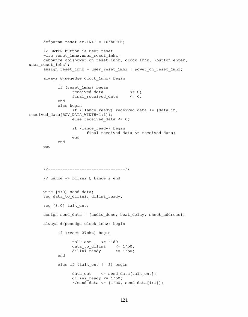
defparam reset_sr.INIT = 16'hFFFF;
// ENTER button is user resetwire reset_1mhz,user_reset_1mhz;debounce db1(power_on_reset_1mhz, clock_1mhz, ~button_enter,
user_reset_1mhz);assign reset_1mhz = user_reset_1mhz | power_on_reset_1mhz;
always @(negedge clock_1mhz) begin
if (reset_1mhz) beginreceived_data <= 0;final_received_data <= 0;
endelse begin
if (!lance_ready) received_data <= {data_in, received_data[RCV_DATA_WIDTH-1:1]};
else received_data <= 0;
if (lance_ready) begin final_received_data <= received_data;
endend
end
//--------------------------------//
// Lance -> Dilini @ Lance's end
wire [4:0] send_data;reg data_to_dilini, dilini_ready;
reg [3:0] talk_cnt;
assign send_data = {audio_done, beat_delay, sheet_address};
always @(posedge clock_1mhz) begin
if (reset_27mhz) begin
talk_cnt <= 4'd0;data_to_dilini <= 1'b0;dilini_ready <= 1'b0;
end
else if (talk_cnt != 5) begin
data_out <= send_data[talk_cnt];dilini_ready <= 1'b0;//send_data <= {1'b0, send_data[4:1]};
121

talk_cnt <= talk_cnt + 1;endelse begin
talk_cnt <= 0;dilini_ready <= 1'b1;
endend
assign clock_1mhz = user1[0];assign data_in = user1[1];assign lance_ready = user1[2];
assign user2[0] = data_out;assign user2[1] = dilini_ready;
endmodule
122

audio_generator.v
module audio_synthesizer #(parameterTESTING=0,
//width of the tick bits in the event player's ROMLOG_TICKS=11,
LOG_TICKS_PER_SECOND=3,
//width of the audio outputAUDIO_WIDTH=18,
LOG_INSTRUMENTS=2,
//the octave played by the sheet_player modulePLAYER_OCTAVE=4,
//the last supported harmonic (supports "1 + this parameter" harmonics)LAST_HARMONIC=4,
//last supported note (supports all notes when this = 11)LAST_NOTE=11,
//last octave (supports "1 + this parameter" octaves)LAST_OCTAVE=7,
//the amount of bits to clip off of sound output to prevent overflowSHIFT_FACTOR=2,
//the length of a beat in samplesSAMPLE_PER_BEAT=256,
//the duration of a quarter note in samplesQRT_DURATION=192,
//samples per second (logarithmic)LOG_SAMPLES=8,
//number of pulses per secondNUM_PULSES=48000,
LOG_HARMONICS=3,LOG_NOTES=4,LOG_OCTAVES=3)
(//allows 6 switches which play keysinput wire [6:0] switch_tone,
//selects the instrument played by the sheet_player moduleinput wire [LOG_INSTRUMENTS-1:0] instrument_switch,
input wire clock,
123

//reset signal from the FPGA or userinput wire global_reset,input wire ready,
//playback signalsinput wire play,input wire pause,input wire stop,
//switches between the event and sheet playersinput wire player_switch,
//outputs from the sheet playerinput wire [15:0] sheet_data,output wire [3:0] sheet_address,
output reg signed [AUDIO_WIDTH-1:0] sound_out);
parameter LOG_KEYS = LOG_NOTES + LOG_OCTAVES;
//width of THETA input to sine moduleparameter THETA_WIDTH = 16;
//width of delta values output by ADSR parameters modulesparameter DELTA_WIDTH = 10;
//same as AUDIO_WIDTHparameter DATA_WIDTH = 18;
//EVENT PLAYER PARAMETERSparameter EVENT_ADDR_WIDTH = 11;parameter EVENT_DATA_WIDTH = 21;
//SHEET PLAYER PARAMETERSparameter SHEET_ADDR_WIDTH=3;parameter SHEET_DATA_WIDTH=16;parameter NOTE_INFO_WIDTH=2;
//SIMULATION PARAMETER SETTINGS (ModelSim doesn't allow long time periods to be recorded
//more must happen within a shorter time period)// parameter SAMPLE_PER_BEAT = 128;// parameter QRT_DURATION=128;// parameter LOG_SAMPLES = 8;// parameter NUM_PULSES = 48000;//parameter LOG_TICKS_PER_SECOND = 3;
// parameter SAMPLE_PER_BEAT = 2;// parameter QRT_DURATION=1;
124
// parameter NUM_PULSES = 16;// parameter LOG_SAMPLES = 2;
parameter SCALE_WIDTH = 8;parameter PRECISION_WIDTH = 16;
localparam [PRECISION_WIDTH-1:0] PULSE_PER_SAMPLE = (NUM_PULSES / (1<<LOG_SAMPLES));
reg [(1<<LOG_INSTRUMENTS)-1:0] keys_pressed [(1<<LOG_KEYS)-1:0];
//reset signal activated by the player modules or changes in the instrument or player
reg reset_internal;
wire reset = (global_reset || stop || reset_internal);
reg playing;wire enable = (ready && playing);reg last_player_switch;reg [LOG_INSTRUMENTS-1:0] last_instrument_switch;
//resets the players when the player or instrument is changedalways @(posedge clock) begin
last_player_switch <= player_switch;last_instrument_switch <= instrument_switch;if (reset) begin
reset_internal <= 1'b0;playing <= 1'b0;
endelse if ((player_switch != last_player_switch) ||
(last_instrument_switch != instrument_switch)) beginreset_internal <= 1'b1;playing <= 1'b0;
endelse begin
reset_internal <= 1'b0;if (play) playing <= 1'b1;else if (pause) playing <= 1'b0;
endend
//---------------------------------------------STAGE SIGNALS--------------------------------------------//
wire stage2_enable;wire [LOG_HARMONICS-1:0] stage2_harmonic_index;
125

wire [LOG_NOTES-1:0] stage2_note_index;wire [LOG_OCTAVES-1:0] stage2_octave_index;
reg stage5_enable, stage3_enable, stage4_enable, stage6_enable;reg [LOG_HARMONICS-1:0] stage5_harmonic_index, stage3_harmonic_index,
stage4_harmonic_index, stage6_harmonic_index;reg [LOG_NOTES-1:0] stage5_note_index, stage3_note_index,
stage4_note_index, stage6_note_index;reg [LOG_OCTAVES-1:0] stage5_octave_index, stage3_octave_index,
stage4_octave_index, stage6_octave_index;//---------------------------------------------STAGE
SIGNALS--------------------------------------------//
wire sample_increment, beat_increment;wire [PRECISION_WIDTH-1:0] pulse_count, sample_count;
overflow_counter #(.COUNT_WIDTH(PRECISION_WIDTH),.MAX_COUNT(PULSE_PER_SAMPLE-1))
pulse_to_sample (.clock(clock),.increment(enable),.restart(reset),
.count(pulse_count),
.overflow(sample_increment));
overflow_counter #(.COUNT_WIDTH(PRECISION_WIDTH),.MAX_COUNT(SAMPLE_PER_BEAT-1))
sample_to_beat (.clock(clock),.increment(sample_increment),.restart(reset),
.count(sample_count),
.overflow(beat_increment));
//*****************************************************************************************
//STAGE 1: GENERATE INDICES FOR SPECIFYING TONES AND THEIR HARMONICS//***********************************************************************
******************
tone_index_selector #(.LAST_OCTAVE(LAST_OCTAVE),.LAST_NOTE(LAST_NOTE),.LAST_HARMONIC(LAST_HARMONIC),.LOG_HARMONICS(LOG_HARMONICS),
126

.LOG_NOTES(LOG_NOTES),
.LOG_OCTAVES(LOG_OCTAVES))tone_index_select (
.clock(clock),
.reset(reset),
.enable_in(enable),
.enable_out(stage2_enable),
.harmonic_index(stage2_harmonic_index),
.note_index(stage2_note_index),
.octave_index(stage2_octave_index));
//*****************************************************************************************
//STAGE 2: GET THETA INCREMENTS AND INITIAL THETA FOR EACH TONE//***********************************************************************
******************
reg [(1<<LOG_INSTRUMENTS)-1:0] instrument_keys;wire [(1<<LOG_INSTRUMENTS)-1:0] mem_keys, combined_keys;
always @(posedge clock) beginif (reset) instrument_keys <= 0;else if (stage2_enable && (stage2_octave_index == 4)) begin
if ((1<<stage2_note_index) & switch_tone) instrument_keys <= (1<<instrument_switch);
else instrument_keys <= 0;endelse instrument_keys <= 0;
end
assign combined_keys = (mem_keys | instrument_keys);
wire done_playing, writable;
wire [LOG_NOTES-1:0] write_note_index, event_write_note_index, sheet_write_note_index;
wire [LOG_OCTAVES-1:0] write_octave_index, event_write_octave_index, sheet_write_octave_index;
wire [LOG_INSTRUMENTS-1:0] write_instrument_index, event_write_instrument_index, sheet_write_instrument_index;
127

wire write_key_pressed, sheet_write_key_pressed, event_write_key_pressed, key_press_we, sheet_key_press_we, event_key_press_we;
//switches inputs the key state RAM depending on the playermux2 #(
.W(LOG_NOTES+LOG_OCTAVES+LOG_INSTRUMENTS+2))m2 (
.sel(player_switch),
.a({sheet_write_note_index, sheet_write_octave_index, sheet_write_instrument_index, sheet_write_key_pressed, sheet_key_press_we}),
.b({event_write_note_index, event_write_octave_index, event_write_instrument_index, event_write_key_pressed, event_key_press_we}),
.z({write_note_index, write_octave_index, write_instrument_index, write_key_pressed, key_press_we})
);
//debug outputs for the two player moduleswire[63:0] sheet_debug;wire[63:0] rose_debug;
//Sheet music for debuggings
//wire [3:0] sheet_address;//wire [15:0] sheet_data;
// little_lamb_sheet lls ( // .index(sheet_address), // .beat_info(sheet_data)// );
sheet_player #(.SHEET_ADDR_WIDTH(SHEET_ADDR_WIDTH),.SHEET_DATA_WIDTH(SHEET_DATA_WIDTH),.NOTE_INFO_WIDTH(NOTE_INFO_WIDTH),
.QRT_DURATION(QRT_DURATION),
.LAST_OCTAVE(LAST_OCTAVE),
.LOG_INSTRUMENTS(LOG_INSTRUMENTS),
.LOG_SAMPLES(LOG_SAMPLES),
.LOG_NOTES(LOG_NOTES),
.LOG_OCTAVES(LOG_OCTAVES),
.LOG_HARMONICS(LOG_HARMONICS))sheet_player1 (
.clock(clock),
.reset(reset),
.enable_in(writable && playing),
//specifies next beat switches to next beat's notes
128

.beat_enable(beat_increment),
//specifies next sample, indicates when the note should beat//turned off in conjunction with the DURATION parameter which//is given in terms of samples.sample_enable(sample_increment),
//this module can only play one octave from one instrument at a time
//this selects which octave and instrument to use.octave_index(PLAYER_OCTAVE),.instrument_index(instrument_switch),
.sheet_data(sheet_data),
.sheet_address(sheet_address),
.done_playing(done_playing),
//OUTPUTS TO KEY PRESS MEMORY.write_note_index(sheet_write_note_index),.write_octave_index(sheet_write_octave_index),.write_instrument_index(sheet_write_instrument_index),.key_pressed(sheet_write_key_pressed),.key_press_we(sheet_key_press_we)
);
key_state_memoryX #(.LOG_INSTRUMENTS(LOG_INSTRUMENTS),.LOG_NOTES(LOG_NOTES),.LOG_OCTAVES(LOG_OCTAVES))
key_mem (.clock(clock),.reset(reset),
//.swap(sample_increment),
.write_enable(key_press_we),
.read_enable(stage2_enable),
.read_note_index(stage2_note_index),
.read_octave_index(stage2_octave_index),
.write_note_index(write_note_index),
.write_octave_index(write_octave_index),
.write_instrument_index(write_instrument_index),
.write_key_pressed(write_key_pressed),
.writable(writable),
.keys_pressed_out(mem_keys));
event_player #(
129
.EVENT_ADDR_WIDTH(EVENT_ADDR_WIDTH),
.EVENT_DATA_WIDTH(EVENT_DATA_WIDTH),
.LOG_TICKS(LOG_TICKS),
.NUM_PULSES(NUM_PULSES),
.LOG_TICKS_PER_SECOND(LOG_TICKS_PER_SECOND),
.LOG_INSTRUMENTS(LOG_INSTRUMENTS),
.PRECISION_WIDTH(PRECISION_WIDTH),
.LOG_NOTES(LOG_NOTES),
.LOG_OCTAVES(LOG_OCTAVES),
.LOG_HARMONICS(LOG_HARMONICS))eplayer (
.clock(clock),
.reset(reset),
.enable(writable && playing && !enable),
.play(playing),
.ready(ready),
//OUTPUTS TO KEY PRESS MEMORY.write_note_index(event_write_note_index),.write_octave_index(event_write_octave_index),.write_instrument_index(event_write_instrument_index),.key_pressed(event_write_key_pressed),.key_press_we(event_key_press_we)
);
wire [THETA_WIDTH-1:0] theta_delta, initial_theta;
tone_theta_params #(.THETA_WIDTH(THETA_WIDTH),.LOG_HARMONICS(LOG_HARMONICS),.LOG_NOTES(LOG_NOTES),.LOG_OCTAVES(LOG_OCTAVES)
)tone_theta_params1 (
.clock(clock),
.reset(reset),
.harmonic_index(stage2_harmonic_index),
.note_index(stage2_note_index),
.octave_index(stage2_octave_index),
.theta_delta(theta_delta),
.initial_theta(initial_theta));
wire [DATA_WIDTH-1:0] tone_mod_data_in;wire signed [DATA_WIDTH+LOG_INSTRUMENTS-1:0] combined_tone_out;wire tone_mod_enable_out;
timbre_transformer #(
130
.LOG_INSTRUMENTS(LOG_INSTRUMENTS),
.DELTA_WIDTH(DELTA_WIDTH),
.DATA_WIDTH(DATA_WIDTH),
.LOG_SAMPLES(LOG_SAMPLES),
.NUM_PULSES(NUM_PULSES),
.SCALE_WIDTH(SCALE_WIDTH),
.PRECISION_WIDTH(PRECISION_WIDTH),
.LAST_HARMONIC(LAST_HARMONIC),
.LOG_HARMONICS(LOG_HARMONICS),
.LOG_NOTES(LOG_NOTES),
.LOG_OCTAVES(LOG_OCTAVES))inst_tone_mod (
.clock(clock),
.reset(reset),
.enable_in(stage2_enable),
.sample_increment(sample_increment),
.instrument_keys(combined_keys),
.harmonic_index(stage2_harmonic_index),
.note_index(stage2_note_index),
.octave_index(stage2_octave_index),
.data_in(tone_mod_data_in),
.enable_out(tone_mod_enable_out),
.combined_tone_out(combined_tone_out));
always @(posedge clock) beginstage3_enable <= stage2_enable;stage3_note_index <= stage2_note_index;stage3_harmonic_index <= stage2_harmonic_index;stage3_octave_index <= stage2_octave_index;
end
//*****************************************************************************************
//STAGE 3: COMPUTE CURRENT THETA VALUES FOR EACH TONE AND STORE//***********************************************************************
******************
wire [THETA_WIDTH-1:0] theta;
theta_increment_memory #(.THETA_WIDTH(THETA_WIDTH),
.LOG_HARMONICS(LOG_HARMONICS),
.LOG_NOTES(LOG_NOTES),
.LOG_OCTAVES(LOG_OCTAVES)
131

)theta_mem (
.clock(clock),
.reset(reset),
.enable_in(stage3_enable),
.harmonic_index(stage3_harmonic_index),
.note_index(stage3_note_index),
.octave_index(stage3_octave_index),
.theta_delta(theta_delta),
.initial_theta(initial_theta),
.theta(theta));
always @(posedge clock) beginstage4_enable <= stage3_enable;stage4_note_index <= stage3_note_index;stage4_harmonic_index <= stage3_harmonic_index;stage4_octave_index <= stage3_octave_index;
end
//*****************************************************************************************
//STAGE 4: COMPUTE SINE FUNCTION VALUES FOR TONE'S THETAS//***********************************************************************
******************
wire rfd, sine_ready;wire [DATA_WIDTH-1:0] sine;
bigsine sinfunc (.THETA(theta),.CLK(clock),.ND(stage4_enable),.RFD(rfd),.RDY(sine_ready),.SINE(sine)
);
assign tone_mod_data_in = sine;
always @(posedge clock) beginstage5_enable <= stage4_enable;stage5_note_index <= stage4_note_index;stage5_harmonic_index <= stage4_harmonic_index;stage5_octave_index <= stage4_octave_index;
end
//*****************************************************************************************
//STAGE 5
132

//*****************************************************************************************
always @(posedge clock) beginstage6_enable <= stage5_enable;stage6_note_index <= stage5_note_index;stage6_harmonic_index <= stage5_harmonic_index;stage6_octave_index <= stage5_octave_index;
end
//*****************************************************************************************
//STAGE 6//***********************************************************************
******************
reg signed [DATA_WIDTH+LOG_OCTAVES+LOG_NOTES+LOG_HARMONICS+LOG_INSTRUMENTS-1:0] aggregate_sound;
//combine sounds together from timbre_transformer//and output sound on ready pulsealways @(posedge clock) begin
if (reset) beginaggregate_sound <= 0;sound_out <= 0;
endelse begin
if (ready) aggregate_sound <= 0;else if (tone_mod_enable_out) begin
aggregate_sound <= aggregate_sound + combined_tone_out;endif (ready) sound_out <= (aggregate_sound>>>SHIFT_FACTOR);
endend
endmodule
audio_gen_submodules.v
/*--------------------------------------------------------------------------------------Module: tone_index_selectorDescription:
Iterates through the all possible tones. Tones are specified by aharmonic, note, and octave index. Outputs an enable signal when it isiterating to indicate to other modules relevant data is beingtransmitted.
Parameters:
133

Defined in Audio Generator Module
Inputs:clock - the clock pulse (27 MHz)reset - sets module back to original stateenable_in - pulse indicating that iteration should restart and begin
Outputs:enable_out - indicates that the Tone Index Selector is outputting index
data (initiates active period of subsequent modules in the pipeline)
harmonic_index - the harmonic indexnote_index - the note indexoctave_index - the octave index
--------------------------------------------------------------------------------------*/
module tone_index_selector #(parameter LOG_HARMONICS=2,LAST_HARMONIC=3,LOG_NOTES=4,LAST_NOTE=11,LOG_OCTAVES=3,LAST_OCTAVE=7)
(input wire clock,input wire reset,input wire enable_in,
output wire enable_out,output wire [LOG_HARMONICS-1:0] harmonic_index,output wire [LOG_NOTES-1:0] note_index,output wire [LOG_OCTAVES-1:0] octave_index
);
//tells the counters to continue incrementingreg increment;
//indicates that all possible indices have been outputwire done;
//indicates to counters that they should reset their countswire restart = (reset || enable_in);
wire note_increment, octave_increment;
//while incrementing, enable_out is set high because//new indicees are being outputassign enable_out = increment;
always @(posedge clock) begin
134

if (reset) beginincrement <= 1'b0;
endelse begin
//when enable_in goes high, begin incrementingif (enable_in) begin
increment <= 1'b1;endelse begin
//stop when last counter overflowsif (done) increment <= 1'b0;
endend
end
//iterates through the harmonic indicesoverflow_counter #(
.COUNT_WIDTH(LOG_HARMONICS),
.MAX_COUNT(LAST_HARMONIC))harmonic_counter (
.clock(clock),
.increment(increment),
.restart(restart),
.count(harmonic_index),
.overflow(note_increment));
//iterates through the note indicesoverflow_counter #(
.COUNT_WIDTH(LOG_NOTES),
.MAX_COUNT(LAST_NOTE))note_counter (
.clock(clock),
.increment(note_increment),
.restart(restart),
.count(note_index),
.overflow(octave_increment));
//iterates through the octave indicesoverflow_counter #(
.COUNT_WIDTH(LOG_OCTAVES),
.MAX_COUNT(LAST_OCTAVE))octave_counter (
.clock(clock),
.increment(octave_increment),
.restart(restart),
.count(octave_index),
.overflow(done));
135

endmodule
/*--------------------------------------------------------------------------------------Module: theta_increment_memoryDescription:
Stores the current value of theta for each tone and increments this value based on
the theta_delta input when enabled.
Parameters:Defined in Audio Generator Module
Inputs:clock - the clock pulse (27 MHz)reset - sets module back to original state (using initial_theta values)enable_in - signals active period
harmonic_index - the harmonic index for the current tone parameter inputsnote_index - the note index for the current tone parameter inputsoctave_index - the octave index for the current tone parameter inputs
-TONE PARAMETER INPUTS-theta_delta - the increase in theta for the specified tone (corresponds
the thefrequency of the tone)
initial_theta - the initial value for theta for a specific tone used whenthe module is uninitialized (first active period or after reset)
Outputs:theta - the new value for theta (old value for theta + theta_delta)
Notes:1. Uses a two-port BRAM. Reads old values from the read port and
writes the new valuesto the write port.
--------------------------------------------------------------------------------------*/
module theta_increment_memory #(parameterTHETA_WIDTH=16,
LOG_HARMONICS=2,LOG_NOTES=4,LOG_OCTAVES=3)
(input wire clock,input wire reset,input wire enable_in,
input wire [LOG_HARMONICS-1:0] harmonic_index,
136
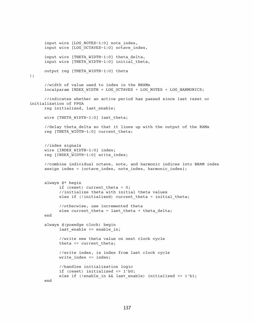
input wire [LOG_NOTES-1:0] note_index,input wire [LOG_OCTAVES-1:0] octave_index,
input wire [THETA_WIDTH-1:0] theta_delta,input wire [THETA_WIDTH-1:0] initial_theta,
output reg [THETA_WIDTH-1:0] theta);
//width of value used to index in the BRAMslocalparam INDEX_WIDTH = LOG_OCTAVES + LOG_NOTES + LOG_HARMONICS;
//indicates whether an active period has passed since last reset or initialization of FPGA
reg initialized, last_enable;
wire [THETA_WIDTH-1:0] last_theta;
//delay theta_delta so that it lines up with the output of the RAMsreg [THETA_WIDTH-1:0] current_theta;
//index signalswire [INDEX_WIDTH-1:0] index;reg [INDEX_WIDTH-1:0] write_index;
//combine individual octave, note, and harmonic indices into BRAM indexassign index = {octave_index, note_index, harmonic_index};
always @* beginif (reset) current_theta = 0;//initialize theta with initial theta valueselse if (!initialized) current_theta = initial_theta;
//otherwise, use incremented thetaelse current_theta = last_theta + theta_delta;
end
always @(posedge clock) beginlast_enable <= enable_in;
//write new theta value on next clock cycletheta <= current_theta;
//write index, is index from last clock cyclewrite_index <= index;
//handles initialization logicif (reset) initialized <= 1'b0;else if (!enable_in && last_enable) initialized <= 1'b1;
end
137
//TWO-PORT BRAM//ALLOWS READING AND WRITINGwrbram #(
.LOGSIZE(INDEX_WIDTH),
.WIDTH(THETA_WIDTH))mem_zero (
.read_addr(index),
.write_addr(write_index),
.clk(clock),
.din(current_theta),
.dout(last_theta),
.we(last_enable && !reset));
endmodule
/*--------------------------------------------------------------------------------------Module: timbre_transformerDescription:
Applies the timbre effects (harmonic relative amplitudes and ADSR envelope scaling)
for the various instruments to the tones. It hooks into multiple stages in the
audio generator pipeline.
Parameters:Defined in Audio Generator Module
Inputs:clock - the clock pulse (27 MHz)reset - sets module back to original statesample_increment - indicates that the envelope should move to the next
sample
-AUDIO GENERATOR STAGE 2 SIGNALS-enable_in - signal to activate processinginstrument_keys - indicates which keys are pressedharmonic_index - the harmonic index for the data going through the audio
generation pipelinenote_index - the note index for the data going through the audio
generation pipelineoctave_index - the octave index for the data going through the audio
generation pipeline
-AUDIO GENERATOR STAGE 4 SIGNALS-data_in - the sine data input
Outputs:-AUDIO GENERATOR STAGE 5 SIGNALS-
138

enable_out - indicates that tone data is being output (initiates active period of
subsequent modules in the pipeline)combined_tone_out - the combined data from all the instrument generators
tone outputs
Notes:1. Timing and synchronization with pipeline is critical since this
module depends onseveral signals from various stages of the pipeline to operate.
2. This module does not truncate the result of adding the instrument tone data so the
width of the combined_tone_out signal is DATA_WIDTH + LOG_INSTRUMENTS.
--------------------------------------------------------------------------------------*/
module timbre_transformer #(parameterLOG_INSTRUMENTS=1,
DELTA_WIDTH=10,DATA_WIDTH=18,LOG_SAMPLES=8,NUM_PULSES=48000,SCALE_WIDTH=8,PRECISION_WIDTH=16,
LAST_HARMONIC=3,LOG_HARMONICS=2,LOG_NOTES=4,LOG_OCTAVES=3)
(
//-------------------DEBUG NETS----------------------//
output wire [18:0] grabbed_scale,
//-------------------DEBUG NETS----------------------//
input wire clock,input wire reset,input wire sample_increment,
input wire enable_in,input wire [(1<<LOG_INSTRUMENTS)-1:0] instrument_keys,input wire [LOG_HARMONICS-1:0] harmonic_index,input wire [LOG_NOTES-1:0] note_index,input wire [LOG_OCTAVES-1:0] octave_index,
input wire [DATA_WIDTH-1:0] data_in,
139
output wire enable_out,output wire signed [DATA_WIDTH+LOG_INSTRUMENTS-1:0] combined_tone_out
);
//---------------------------------------------STAGE SIGNALS--------------------------------------------//
reg stage2_enable, stage3_enable, stage4_enable;reg [LOG_HARMONICS-1:0] stage2_harmonic_index, stage3_harmonic_index,
stage4_harmonic_index;reg [LOG_NOTES-1:0] stage2_note_index, stage3_note_index,
stage4_note_index;reg [LOG_OCTAVES-1:0] stage2_octave_index, stage3_octave_index,
stage4_octave_index;//-----------------------------------------------------------------------
------------------------------//
//Instrument index parametersparameter [LOG_INSTRUMENTS-1:0] PIANO_INDEX = 0;parameter [LOG_INSTRUMENTS-1:0] VIOLIN_INDEX = 1;parameter [LOG_INSTRUMENTS-1:0] WHISTLE_INDEX = 2;parameter [LOG_INSTRUMENTS-1:0] CELLO_INDEX = 3;
//get key press information for instruments based on their indexwire piano_key_pressed = instrument_keys[PIANO_INDEX];wire violin_key_pressed = instrument_keys[VIOLIN_INDEX];wire whistle_key_pressed = instrument_keys[WHISTLE_INDEX];wire cello_key_pressed = instrument_keys[CELLO_INDEX];
//***************************************************************//STAGE 1 - AUDIO GENERATOR PIPE STAGE 2//***************************************************************
//---------------------------------------------------------------//PIANO ADSR PROPERTIES//---------------------------------------------------------------
wire [LOG_SAMPLES-1:0] piano_attack_duration;wire [DELTA_WIDTH-1:0] piano_attack_delta;
wire [LOG_SAMPLES-1:0] piano_decay_duration;wire [DELTA_WIDTH-1:0] piano_decay_delta;
wire [DELTA_WIDTH-1:0] piano_sustain_delta;wire [LOG_SAMPLES-1:0] piano_sustain_factor;
wire [DELTA_WIDTH-1:0] piano_release_delta;
piano_asdr_props #(.LOG_SAMPLES(LOG_SAMPLES),.DELTA_WIDTH(DELTA_WIDTH)
)piano_envelope_params (
140

.attack_duration(piano_attack_duration),
.attack_delta(piano_attack_delta),
.decay_duration(piano_decay_duration),
.decay_delta(piano_decay_delta),
.sustain_delta(piano_sustain_delta),
.sustain_factor(piano_sustain_factor),
.release_delta(piano_release_delta));
//---------------------------------------------------------------//VIOLIN ADSR PROPERTIES//---------------------------------------------------------------
wire [LOG_SAMPLES-1:0] violin_attack_duration;wire [DELTA_WIDTH-1:0] violin_attack_delta;
wire [LOG_SAMPLES-1:0] violin_decay_duration;wire [DELTA_WIDTH-1:0] violin_decay_delta;
wire [DELTA_WIDTH-1:0] violin_sustain_delta;wire [LOG_SAMPLES-1:0] violin_sustain_factor;
wire [DELTA_WIDTH-1:0] violin_release_delta;
violin_asdr_props #(.LOG_SAMPLES(LOG_SAMPLES),.DELTA_WIDTH(DELTA_WIDTH)
)violin_envelope_params (
.clock(clock),
.reset(reset),
.sample_increment(sample_increment),
.attack_duration(violin_attack_duration),
.attack_delta(violin_attack_delta),
.decay_duration(violin_decay_duration),
.decay_delta(violin_decay_delta),
.sustain_delta(violin_sustain_delta),
.sustain_factor(violin_sustain_factor),
.release_delta(violin_release_delta));
//---------------------------------------------------------------//WHISTLE ADSR PROPERTIES//---------------------------------------------------------------
wire [LOG_SAMPLES-1:0] whistle_attack_duration;wire [DELTA_WIDTH-1:0] whistle_attack_delta;
141

wire [LOG_SAMPLES-1:0] whistle_decay_duration;wire [DELTA_WIDTH-1:0] whistle_decay_delta;
wire [DELTA_WIDTH-1:0] whistle_sustain_delta;wire [LOG_SAMPLES-1:0] whistle_sustain_factor;
wire [DELTA_WIDTH-1:0] whistle_release_delta;
whistle_asdr_props #(.LOG_SAMPLES(LOG_SAMPLES),.DELTA_WIDTH(DELTA_WIDTH)
)whistle_envelope_params (
.attack_duration(whistle_attack_duration),
.attack_delta(whistle_attack_delta),
.decay_duration(whistle_decay_duration),
.decay_delta(whistle_decay_delta),
.sustain_delta(whistle_sustain_delta),
.sustain_factor(whistle_sustain_factor),
.release_delta(whistle_release_delta));
//---------------------------------------------------------------//PIANO GENERATOR//---------------------------------------------------------------
wire [SCALE_WIDTH-1:0] piano_harmonic_scale;wire [LOG_HARMONICS-1:0] piano_harmonic_scale_index;wire piano_enable_out;wire signed [DATA_WIDTH-1:0] piano_tone_data;
instrument_generator #(.DELTA_WIDTH(DELTA_WIDTH),.DATA_WIDTH(DATA_WIDTH),.LOG_SAMPLES(LOG_SAMPLES),.NUM_PULSES(NUM_PULSES),.SCALE_WIDTH(SCALE_WIDTH),.PRECISION_WIDTH(PRECISION_WIDTH),
.LAST_HARMONIC(LAST_HARMONIC),
.LOG_HARMONICS(LOG_HARMONICS),
.LOG_NOTES(LOG_NOTES),
.LOG_OCTAVES(LOG_OCTAVES))piano_generator (
//-------------------DEBUG NETS----------------------//
.grabbed_scale(grabbed_scale),
142
//-------------------DEBUG NETS----------------------//
.clock(clock),
.reset(reset),
.enable_in(enable_in),
.sample_increment(sample_increment),
.harmonic_index(harmonic_index),
.note_index(note_index),
.octave_index(octave_index),
.key_pressed(piano_key_pressed),
.attack_duration(piano_attack_duration),
.attack_delta(piano_attack_delta),
.decay_duration(piano_decay_duration),
.decay_delta(piano_decay_delta),
.sustain_delta(piano_sustain_delta),
.sustain_factor(piano_sustain_factor),
.release_delta(piano_release_delta),
.harmonic_scale(piano_harmonic_scale),
.harmonic_scale_index(piano_harmonic_scale_index),
.tone_data_in (data_in),
.enable_out(piano_enable_out),
.tone_data_out(piano_tone_data));
piano_harmonic_scale_params #(.SCALE_WIDTH(SCALE_WIDTH),.LOG_HARMONICS(LOG_HARMONICS)
)piano_harmonic_scale_params1 (
.clock(clock),
.reset(reset),
.harmonic_index(piano_harmonic_scale_index),
.harmonic_scale(piano_harmonic_scale));
//---------------------------------------------------------------//VIOLIN GENERATOR//---------------------------------------------------------------
wire [SCALE_WIDTH-1:0] violin_harmonic_scale;wire [LOG_HARMONICS-1:0] violin_harmonic_scale_index;
143

wire violin_enable_out;wire signed [DATA_WIDTH-1:0] violin_tone_data;
instrument_generator #(.DELTA_WIDTH(DELTA_WIDTH),.DATA_WIDTH(DATA_WIDTH),.LOG_SAMPLES(LOG_SAMPLES),.NUM_PULSES(NUM_PULSES),.SCALE_WIDTH(SCALE_WIDTH),.PRECISION_WIDTH(PRECISION_WIDTH),
.LAST_HARMONIC(LAST_HARMONIC),
.LOG_HARMONICS(LOG_HARMONICS),
.LOG_NOTES(LOG_NOTES),
.LOG_OCTAVES(LOG_OCTAVES))violin_generator (
.clock(clock),
.reset(reset),
.enable_in(enable_in),
.sample_increment(sample_increment),
.harmonic_index(harmonic_index),
.note_index(note_index),
.octave_index(octave_index),
.key_pressed(violin_key_pressed),
.attack_duration(violin_attack_duration),
.attack_delta(violin_attack_delta),
.decay_duration(violin_decay_duration),
.decay_delta(violin_decay_delta),
.sustain_delta(violin_sustain_delta),
.sustain_factor(violin_sustain_factor),
.release_delta(violin_release_delta),
.harmonic_scale(violin_harmonic_scale),
.harmonic_scale_index(violin_harmonic_scale_index),
.tone_data_in (data_in),
.enable_out(violin_enable_out),
.tone_data_out(violin_tone_data));
violin_harmonic_scale_params #(.SCALE_WIDTH(SCALE_WIDTH),.LOG_HARMONICS(LOG_HARMONICS)
)violin_harmonic_scale_params1 (
144

.clock(clock),
.reset(reset),
.harmonic_index(violin_harmonic_scale_index),
.harmonic_scale(violin_harmonic_scale));
//---------------------------------------------------------------//WHISTLE GENERATOR//---------------------------------------------------------------
wire [SCALE_WIDTH-1:0] whistle_harmonic_scale;wire [LOG_HARMONICS-1:0] whistle_harmonic_scale_index;wire whistle_enable_out;wire signed [DATA_WIDTH-1:0] whistle_tone_data;
instrument_generator #(.DELTA_WIDTH(DELTA_WIDTH),.DATA_WIDTH(DATA_WIDTH),.LOG_SAMPLES(LOG_SAMPLES),.NUM_PULSES(NUM_PULSES),.SCALE_WIDTH(SCALE_WIDTH),.PRECISION_WIDTH(PRECISION_WIDTH),
.LAST_HARMONIC(LAST_HARMONIC),
.LOG_HARMONICS(LOG_HARMONICS),
.LOG_NOTES(LOG_NOTES),
.LOG_OCTAVES(LOG_OCTAVES))whistle_generator (
.clock(clock),
.reset(reset),
.enable_in(enable_in),
.sample_increment(sample_increment),
.harmonic_index(harmonic_index),
.note_index(note_index),
.octave_index(octave_index),
.key_pressed(whistle_key_pressed),
.attack_duration(whistle_attack_duration),
.attack_delta(whistle_attack_delta),
.decay_duration(whistle_decay_duration),
.decay_delta(whistle_decay_delta),
.sustain_delta(whistle_sustain_delta),
.sustain_factor(whistle_sustain_factor),
.release_delta(whistle_release_delta),
145

.harmonic_scale(whistle_harmonic_scale),
.harmonic_scale_index(whistle_harmonic_scale_index),
.tone_data_in (data_in),
.enable_out(whistle_enable_out),
.tone_data_out(whistle_tone_data));
whistle_harmonic_scale_params #(.SCALE_WIDTH(SCALE_WIDTH),.LOG_HARMONICS(LOG_HARMONICS)
)whistle_harmonic_scale_params1 (
.clock(clock),
.reset(reset),
.harmonic_index(whistle_harmonic_scale_index),
.harmonic_scale(whistle_harmonic_scale));
//---------------------------------------------------------------//CELLO GENERATOR//---------------------------------------------------------------
wire [SCALE_WIDTH-1:0] cello_harmonic_scale;wire [LOG_HARMONICS-1:0] cello_harmonic_scale_index;wire cello_enable_out;wire signed [DATA_WIDTH-1:0] cello_tone_data;
instrument_generator #(.DELTA_WIDTH(DELTA_WIDTH),.DATA_WIDTH(DATA_WIDTH),.LOG_SAMPLES(LOG_SAMPLES),.NUM_PULSES(NUM_PULSES),.SCALE_WIDTH(SCALE_WIDTH),.PRECISION_WIDTH(PRECISION_WIDTH),
.LAST_HARMONIC(LAST_HARMONIC),
.LOG_HARMONICS(LOG_HARMONICS),
.LOG_NOTES(LOG_NOTES),
.LOG_OCTAVES(LOG_OCTAVES))cello_generator (
.clock(clock),
.reset(reset),
.enable_in(enable_in),
.sample_increment(sample_increment),
.harmonic_index(harmonic_index),
146

.note_index(note_index),
.octave_index(octave_index),
.key_pressed(cello_key_pressed),
.attack_duration(violin_attack_duration),
.attack_delta(violin_attack_delta),
.decay_duration(violin_decay_duration),
.decay_delta(violin_decay_delta),
.sustain_delta(violin_sustain_delta),
.sustain_factor(violin_sustain_factor),
.release_delta(violin_release_delta),
.harmonic_scale(cello_harmonic_scale),
.harmonic_scale_index(cello_harmonic_scale_index),
.tone_data_in (data_in),
.enable_out(cello_enable_out),
.tone_data_out(cello_tone_data));
cello_harmonic_scale_params #(.SCALE_WIDTH(SCALE_WIDTH),.LOG_HARMONICS(LOG_HARMONICS)
)cello_harmonic_scale_params1 (
.clock(clock),
.reset(reset),
.harmonic_index(cello_harmonic_scale_index),
.harmonic_scale(cello_harmonic_scale));
//***************************************************************//STAGE 4 - AUDIO GENERATOR STAGE 5//***************************************************************
//combined enable out and tone signals (all instruments enable and tone data signals should coincide)
assign enable_out = (violin_enable_out && piano_enable_out && whistle_enable_out && cello_enable_out);
assign combined_tone_out = (violin_tone_data + piano_tone_data +whistle_tone_data + cello_tone_data);
endmodule
147
/*--------------------------------------------------------------------------------------Module: instrument_generatorDescription:
Generic module which connects with a harmonic parameters and ADSR parameters module to
apply the timbre effects for a particular instrument.
Parameters:Defined in Audio Generator Module
Inputs:clock - the clock pulse (27 MHz)reset - sets module back to original statesample_increment - indicates that the envelope should move to the next
sample
-AUDIO GENERATOR STAGE 2 SIGNALS-enable_in - signal to activate processingkey_pressed - indicates whether the key specified by the indices is
pressedharmonic_index - the harmonic index for the data going through the audio
generation pipelinenote_index - the note index for the data going through the audio
generation pipelineoctave_index - the octave index for the data going through the audio
generation pipeline
-INSTRUMENT ADSR PROPERTIES-attack_duration - the length in samples of the attack period of the ADSR
envelope_generatorattack_delta - the change in amplitude of the signal per sample for the
attack period(first SCALE_WIDTH are integral part, rest are fractional)
decay_duration - the length in samples of the decay period of the ADSR envelope_generator
decay_delta - the change in amplitude of the signal per sample for the decay period
(first SCALE_WIDTH are integral part, rest are fractional)
sustain_delta - the change in amplitude of the signal per sample as mediated by the sustain factor
for the sustain period (first SCALE_WIDTH bits are integral part, the rest are fractional)
sustain_factor - the number of samples that passes before the sustain_delta is
applied to the signal again (allows for smaller decreases in amplitude over time)
release_delta - the change in amplitude of the signal per sample for the release period
148
-HARMONIC SCALE INPUTS (AUDIO GENERATOR STAGE 4)-harmonic_scale - the scale factor (relative amplitude) for the
harmonic_scale_index output on the last clock cycle
Outputs:enable_out - indicates that the Tone Selector is outputting index dataharmonic_index - the harmonic indexnote_index - the note indexoctave_index - the octave index
Notes:1. Make sure MAX_COUNT is within the range of numbers possible given
COUNT_WIDTH, otherwise, there will never be overflow.
--------------------------------------------------------------------------------------*/
module instrument_generator #(parameterDELTA_WIDTH=10,DATA_WIDTH=18,LOG_SAMPLES=8,NUM_PULSES=48000,SCALE_WIDTH=8,PRECISION_WIDTH=16,
LAST_HARMONIC=3,LOG_HARMONICS=2,LOG_NOTES=4,LOG_OCTAVES=3)
(//-------------------DEBUG NETS----------------------//
output wire [18:0] grabbed_scale,
//-------------------DEBUG NETS----------------------//input wire clock,input wire reset,input wire enable_in,
input wire sample_increment,
input wire [LOG_HARMONICS-1:0] harmonic_index,input wire [LOG_NOTES-1:0] note_index,input wire [LOG_OCTAVES-1:0] octave_index,
input wire key_pressed,
//INSTRUMENT ADSR PROPERTIESinput wire [LOG_SAMPLES-1:0] attack_duration,
149
input wire signed [DELTA_WIDTH-1:0] attack_delta,
input wire [LOG_SAMPLES-1:0] decay_duration,input wire signed [DELTA_WIDTH-1:0] decay_delta,
input wire signed [DELTA_WIDTH-1:0] sustain_delta,input wire [LOG_SAMPLES-1:0] sustain_factor,
input wire signed [DELTA_WIDTH-1:0] release_delta,
//HARMONIC SCALE FACTORinput wire [SCALE_WIDTH-1:0] harmonic_scale,output wire [LOG_HARMONICS-1:0] harmonic_scale_index,
//SINE DATAinput wire [DATA_WIDTH-1:0] tone_data_in,
output reg enable_out,output reg signed [DATA_WIDTH-1:0] tone_data_out
);
parameter LOG_KEYS = LOG_OCTAVES + LOG_NOTES;parameter NOTE_INFO_WIDTH = LOG_SAMPLES + PRECISION_WIDTH + DELTA_WIDTH +
2;
reg stage2_enable, stage3_enable, stage4_enable;reg [LOG_HARMONICS-1:0] stage2_harmonic_index, stage3_harmonic_index,
stage4_harmonic_index;reg [LOG_NOTES-1:0] stage2_note_index, stage3_note_index,
stage4_note_index;reg [LOG_OCTAVES-1:0] stage2_octave_index, stage3_octave_index,
stage4_octave_index;
//***************************************************************//STAGE 1 - AUDIO GENERATOR STAGE 2//***************************************************************
wire [NOTE_INFO_WIDTH-1:0] read_note_info, write_note_info;//assign read_note_info [NOTE_INFO_WIDTH-1:36] = 0;wire note_info_we;reg [LOG_KEYS-1:0] write_key_index;
reg [LOG_KEYS-1:0] read_addr=0;reg [LOG_KEYS-1:0] write_addr=0;
always @* beginread_addr[LOG_KEYS-1:0] = {octave_index, note_index};write_addr[LOG_KEYS-1:0] = write_key_index;
end
//Stores note ADSR state infowrbram #(
150

.LOGSIZE(LOG_KEYS),
.WIDTH(NOTE_INFO_WIDTH))note_state_info (
.read_addr(read_addr),
.write_addr(write_addr),
.clk(clock),
.din(write_note_info),
.dout(read_note_info),
.we(note_info_we));
reg adsr_initialized;wire [SCALE_WIDTH-1:0] adsr_scale;
//ATTACHMENTS BETWEEN NOTE STATE INFO MODULE AND ASDR SCALE GENERATORwire adsr_enout;wire [1:0] last_adsr_state;wire [LOG_SAMPLES-1:0] last_adsr_count;wire [DELTA_WIDTH+PRECISION_WIDTH-1:0] last_adsr_factor;
wire [1:0] adsr_state;wire [LOG_SAMPLES-1:0] adsr_count;wire [DELTA_WIDTH+PRECISION_WIDTH-1:0] adsr_factor;assign write_note_info = {adsr_state, adsr_count, adsr_factor};assign {last_adsr_state, last_adsr_count, last_adsr_factor} =
(adsr_initialized ? read_note_info : 0);
assign note_info_we = adsr_enout;
//passed along enable signals and indices to the next stage2_enable//last clock cycles read index, is this clock cycles write indexalways @(posedge clock) begin
if (reset) adsr_initialized <= 1'b0;else if(stage2_enable && !enable_in) adsr_initialized <= 1'b1;
stage2_enable <= enable_in;stage2_note_index <= note_index;stage2_harmonic_index <= harmonic_index;stage2_octave_index <= octave_index;
write_key_index <= {stage2_octave_index, stage2_note_index};
end
//***************************************************************//STAGE 2 - AUDIO GENERATOR STAGE 3//***************************************************************
adsr_scale_generator #(//parameters
151

.DELTA_WIDTH(DELTA_WIDTH),
.NUM_PULSES(NUM_PULSES),
.SCALE_WIDTH(SCALE_WIDTH),
.LOG_SAMPLES(LOG_SAMPLES),
.PRECISION_WIDTH(PRECISION_WIDTH),
.LAST_HARMONIC(LAST_HARMONIC),
.LOG_HARMONICS(LOG_HARMONICS),
.LOG_NOTES(LOG_NOTES),
.LOG_OCTAVES(LOG_OCTAVES))envelope_generator (
//inputs.clock(clock),.reset(reset),.enable(stage2_enable),
.sample_increment(sample_increment),
.note_index(stage2_note_index),
.harmonic_index(stage2_harmonic_index),
.octave_index(stage2_octave_index),
.note_pressed(key_pressed),
.last_state(last_adsr_state),
.last_count(last_adsr_count),
.last_factor(last_adsr_factor),
.attack_duration(attack_duration),
.attack_delta(attack_delta),
.decay_duration(decay_duration),
.decay_delta(decay_delta),
.sustain_delta(sustain_delta),
.sustain_factor(sustain_factor),
.release_delta(release_delta),
//outputs.state(adsr_state),.count(adsr_count),.factor(adsr_factor),.write_state_info(adsr_enout),.scale(adsr_scale)
);
reg [SCALE_WIDTH-1:0] scale;wire [SCALE_WIDTH-1:0] scale_async;
assign harmonic_scale_index = stage2_harmonic_index;
152

always @(posedge clock) beginstage3_enable <= stage2_enable;stage3_note_index <= stage2_note_index;stage3_harmonic_index <= stage2_harmonic_index;stage3_octave_index <= stage2_octave_index;
//synchronize harmonic scale generator outputscale <= scale_async;
end
//***************************************************************//STAGE 3 - AUDIO GENERATOR STAGE 4//***************************************************************
positive_scaler #(//parameters.DATA_WIDTH(SCALE_WIDTH),.SCALE_WIDTH(SCALE_WIDTH)
)harmonic_scale_generator (
//inputs.clock(clock),.reset(reset),.enable(stage3_enable),.data(harmonic_scale),.factor(adsr_scale),
//outputs.product(scale_async)
);
wire [DATA_WIDTH-1:0] scaled_tone_data_async;
always @(posedge clock) beginstage4_enable <= stage3_enable;stage4_note_index <= stage3_note_index;stage4_harmonic_index <= stage3_harmonic_index;stage4_octave_index <= stage3_octave_index;
end
//***************************************************************//STAGE 4 - AUDIO GENERATOR STAGE 5//***************************************************************
scaler #(//parameters.DATA_WIDTH(DATA_WIDTH),.SCALE_WIDTH(SCALE_WIDTH)
)note_scaler (
//inputs.clock(clock),.reset(reset),
153

.enable(stage4_enable),
.data(tone_data_in),
.factor(scale),
//outputs.product(scaled_tone_data_async)
);
always @(posedge clock) begintone_data_out <= scaled_tone_data_async;enable_out <= stage4_enable;
end
//---------------------------------------------DEBUG ZONE--------------------------------------------//
reg stage3_key_pressed;always @(posedge clock) begin
stage3_key_pressed <= key_pressed;end
sample_filter #(//parameters.DATA_WIDTH(19)
)scale_grabber (
//inputs.clock(clock),.reset(reset),.enable(stage3_enable && (stage3_harmonic_index == 0) &&
(stage3_note_index == 0) && (stage3_octave_index == 3)),.data({stage3_key_pressed, adsr_state, adsr_scale, adsr_count}),//.sample_index(sample_index),//.index(note_index_out),
//outputs.data_out(grabbed_scale)
);
//---------------------------------------------DEBUG ZONE--------------------------------------------//
endmodule
module adsr_scale_generator #(parameterLOG_SAMPLES=8,NUM_PULSES=48000,DELTA_WIDTH=10,SCALE_WIDTH=8,
154

PRECISION_WIDTH=8,
LAST_HARMONIC=0,LOG_HARMONICS=2,LOG_NOTES=4,LOG_OCTAVES=3)
(//STANDARD PIPE SIGNALSinput wire clock,input wire reset,input wire enable,
input wire sample_increment,
//NOTE INFORMATIONinput wire [LOG_HARMONICS-1:0] harmonic_index,input wire [LOG_NOTES-1:0] note_index,input wire [LOG_OCTAVES-1:0] octave_index,input wire note_pressed,
//STATE INFORMATIONinput wire [1:0] last_state,input wire [LOG_SAMPLES-1:0] last_count,input wire [DELTA_WIDTH+PRECISION_WIDTH-1:0] last_factor,
//INSTRUMENT ADSR PROPERTIESinput wire [LOG_SAMPLES-1:0] attack_duration,input wire signed [DELTA_WIDTH-1:0] attack_delta,
input wire [LOG_SAMPLES-1:0] decay_duration,input wire signed [DELTA_WIDTH-1:0] decay_delta,
input wire signed [DELTA_WIDTH-1:0] sustain_delta,input wire [LOG_SAMPLES-1:0] sustain_factor,
input wire signed [DELTA_WIDTH-1:0] release_delta,
//OUTPUT STATE INFORMATIONoutput reg [1:0] state,output reg [LOG_SAMPLES-1:0] count,output reg [DELTA_WIDTH+PRECISION_WIDTH-1:0] factor,output reg write_state_info,
output wire [SCALE_WIDTH-1:0] scale);
parameter [LOG_HARMONICS-1:0] FUNDAMENTAL = 0;
//ADSR State Parametersparameter S_RELEASE = 0;parameter S_ATTACK = 1;parameter S_DECAY = 2;parameter S_SUSTAIN = 3;
155

reg last_enable, next_sample;
reg [1:0] next_state;
//Only update on the first harmonic, the rest will have the same ADSR information
wire enable_adsr = (enable && (harmonic_index == 0));
parameter FACTOR_WIDTH = DELTA_WIDTH + PRECISION_WIDTH;
always @* beginif (reset) begin
next_state = S_RELEASE;endelse begin
if (enable_adsr) beginif (!note_pressed) begin
next_state = S_RELEASE;endelse begin
case (last_state)S_ATTACK :
if ((last_count == attack_duration) || last_factor[FACTOR_WIDTH-1]) next_state = S_DECAY;
else next_state = S_ATTACK;S_DECAY : next_state = ((last_count ==
decay_duration) ? S_SUSTAIN : S_DECAY);S_SUSTAIN: next_state = S_SUSTAIN;S_RELEASE: next_state = (note_pressed ?
S_ATTACK : S_RELEASE);default: next_state = S_RELEASE;
endcaseend
endend
end
reg [DELTA_WIDTH-1:0] delta;
always @* begincase (last_state)
S_ATTACK : delta = attack_delta;S_DECAY : delta = decay_delta;S_SUSTAIN: delta = ((last_count == 0) ? sustain_delta : 0);S_RELEASE: delta = release_delta;default: delta = 0;
endcaseend
high_extractor #(.DATA_WIDTH(FACTOR_WIDTH),.LEFT_OFFSET(0),
156

.EXTRACT_WIDTH(SCALE_WIDTH))scale_extractor (
.data(factor),
.extraction(scale));
wire [FACTOR_WIDTH-1:0] factor_result;
//update teh factor values based on the delta (updates are fractional since the are multiple
//ready pulses between samples)interpolator #(
.DELTA_WIDTH(DELTA_WIDTH),
.LOG_SAMPLES(LOG_SAMPLES),
.NUM_PULSES(NUM_PULSES),
.PRECISION_WIDTH(PRECISION_WIDTH))interpolator1 (
.data_in(last_factor),
.delta(delta),
.data_out(factor_result));
always @(posedge clock) beginif (reset) begin
state <= S_RELEASE;write_state_info <= 1'b0;factor <= 0;count <= 0;last_enable <= 0;
endelse begin
last_enable <= enable;
//next sample needs to be set for an entire active cycle (until negedge enable)
if (sample_increment) next_sample <= 1'b1;else if (!enable && last_enable) next_sample <= 1'b0;
//write state info when enabledwrite_state_info <= enable_adsr;
if (enable_adsr) begin
if (factor_result[FACTOR_WIDTH-1]) factor <= (1<<(FACTOR_WIDTH-1));
else factor <= factor_result;
157
state <= next_state;//SET 'count' valueif (last_state != next_state) begin
count <= 0;endelse begin
//only change count, when the next sample signal is received
if (next_sample) beginif (last_state == S_SUSTAIN) begin
if (last_count == sustain_factor) count <= 0;
else count <= last_count + 1;endelse begin
count <= last_count + 1;end
endelse begin
count <= last_count;end
end
endelse begin
state <= S_RELEASE;count <= 0;
endend
end
endmodule
audio_gen_data.v
/*--------------------------------------------------------------------------------------Module: tone_theta_paramsDescription:
Outputs the per ready pulse change in theta (aka frequency) and the initial theta
value (phase) for a given tone (octave, note, harmonic).
Parameters:Defined in Audio Generator Module
Inputs:
158

clock - the clock pulse (27 MHz)harmonic_index - the harmonic indexnote_index - the note indexoctave_index - the octave index
Outputs:theta_delta - the change in theta for each ready pulse (corresponds to
frequency)initial_theta - the initial value for theta when a tone begins
(corresponds to phase)
Notes:1. The initial theta is the same for all instruments under the current
scheme.These phases were derived from violin signals, so they may not be
compatible forother instruments.
--------------------------------------------------------------------------------------*/
module tone_theta_params #(parameterTHETA_WIDTH=16,
LOG_HARMONICS=2,LOG_NOTES=4,LOG_OCTAVES=3)
(input wire clock,input wire reset,
input wire [LOG_HARMONICS-1:0] harmonic_index,input wire [LOG_NOTES-1:0] note_index,input wire [LOG_OCTAVES-1:0] octave_index,
output reg [THETA_WIDTH-1:0] theta_delta,output reg [THETA_WIDTH-1:0] initial_theta
);
//note name parametersparameter [LOG_NOTES-1:0] C = 0;parameter [LOG_NOTES-1:0] Cs = 1;parameter [LOG_NOTES-1:0] D = 2;parameter [LOG_NOTES-1:0] Ds = 3;parameter [LOG_NOTES-1:0] E = 4;parameter [LOG_NOTES-1:0] F = 5;parameter [LOG_NOTES-1:0] Fs = 6;parameter [LOG_NOTES-1:0] G = 7;parameter [LOG_NOTES-1:0] Gs = 8;parameter [LOG_NOTES-1:0] A = 9;parameter [LOG_NOTES-1:0] As = 10;parameter [LOG_NOTES-1:0] B = 11;
//harmonic name parameters
159

parameter [LOG_HARMONICS-1:0] FND = 0;parameter [LOG_HARMONICS-1:0] SECOND = 1;parameter [LOG_HARMONICS-1:0] THIRD = 2;parameter [LOG_HARMONICS-1:0] FOURTH = 3;parameter [LOG_HARMONICS-1:0] FIFTH = 4;
//specifies the octave index which is represented by the constants belowparameter [LOG_OCTAVES-1:0] INITIAL_OCTAVE_INDEX = 7;
//constant is divided by 2^octave_attentuation to get the theta delta//corresponding to the fundamental frequency for a particular note and
octavewire [LOG_OCTAVES-1:0] octave_attentuation = INITIAL_OCTAVE_INDEX -
octave_index;
//multiply the fundamental by this number to give the harmonic's theta delta (frequency)
wire [LOG_HARMONICS:0] harmonic_number = harmonic_index + 1;
reg [THETA_WIDTH-1:0] base_delta;
always @* begincase (note_index)
C: base_delta = 16'd2857;Cs: base_delta = 16'd3027;D: base_delta = 16'd3207;Ds: base_delta = 16'd3398;E: base_delta = 16'd3600;F: base_delta = 16'd3814;Fs: base_delta = 16'd4041;G: base_delta = 16'd4281;Gs: base_delta = 16'd4536;A: base_delta = 16'd4806;As: base_delta = 16'd5091;B: base_delta = 16'd5394;default: base_delta = 16'd0;
endcaseend
always @(posedge clock) begin//assign theta_delta (frequency) for a given note, octave, and
harmonictheta_delta <= ((base_delta >> octave_attentuation) *
harmonic_number);
//assign initial_theta (phase) for each harmoniccase (harmonic_index)
FND: initial_theta <= 16'd32982;SECOND: initial_theta <= 16'd9174;THIRD: initial_theta <= 16'd46992;FOURTH: initial_theta <= 16'd26623;FIFTH: initial_theta <= 16'd59455;default: initial_theta <= 16'd0;
160

endcaseend
endmodule
/*--------------------------------------------------------------------------------------Modules: violin_harmonic_scale_params, piano_harmonic_scale_params,
cello_harmonic_scale_params, whistle_harmonic_scale_paramsDescription:
Outputs the scale factor which corresponds to the relative amplitude of the
input harmonic index
Parameters:Defined in Audio Generator Module
Inputs:clock - the clock pulse (27 MHz)reset - the reset signalharmonic_index - the harmonic index
Outputs:harmonic_scale - the scale factor for the harmonic
--------------------------------------------------------------------------------------*/
module violin_harmonic_scale_params #(parameter SCALE_WIDTH=8,LOG_HARMONICS=3)
(input wire clock,input wire reset,input wire [LOG_HARMONICS-1:0] harmonic_index,
output reg [SCALE_WIDTH-1:0] harmonic_scale);
parameter [LOG_HARMONICS-1:0] FND = 0;parameter [LOG_HARMONICS-1:0] SECOND = 1;parameter [LOG_HARMONICS-1:0] THIRD = 2;parameter [LOG_HARMONICS-1:0] FOURTH = 3;parameter [LOG_HARMONICS-1:0] FIFTH = 4;
always @(posedge clock) begincase(harmonic_index)
FND: harmonic_scale <= 8'd128;SECOND: harmonic_scale <= 8'd39;THIRD: harmonic_scale <= 8'd18;FOURTH: harmonic_scale <= 8'd69;FIFTH: harmonic_scale <= 8'd53;default: harmonic_scale <= 8'd0;
161

endcaseend
endmodule
module piano_harmonic_scale_params #(parameter SCALE_WIDTH=8,LOG_HARMONICS=3)
(input wire clock,input wire reset,input wire [LOG_HARMONICS-1:0] harmonic_index,
output reg [SCALE_WIDTH-1:0] harmonic_scale);
parameter [LOG_HARMONICS-1:0] FND = 0;parameter [LOG_HARMONICS-1:0] SECOND = 1;parameter [LOG_HARMONICS-1:0] THIRD = 2;parameter [LOG_HARMONICS-1:0] FOURTH = 3;
always @(posedge clock) begincase(harmonic_index)
FND: harmonic_scale <= 8'd128;SECOND: harmonic_scale <= 8'd68;THIRD: harmonic_scale <= 8'd23;FOURTH: harmonic_scale <= 8'd22;default: harmonic_scale <= 8'd0;
endcaseend
endmodule
module whistle_harmonic_scale_params #(parameter SCALE_WIDTH=8,LOG_HARMONICS=3)
(input wire clock,input wire reset,input wire [LOG_HARMONICS-1:0] harmonic_index,
output reg [SCALE_WIDTH-1:0] harmonic_scale);
parameter [LOG_HARMONICS-1:0] FND = 0;
always @(posedge clock) begincase(harmonic_index)
FND: harmonic_scale <= 8'd128;default: harmonic_scale <= 8'd0;
endcaseend
162

endmodule
module cello_harmonic_scale_params #(parameter SCALE_WIDTH=8,LOG_HARMONICS=3)
(input wire clock,input wire reset,input wire [LOG_HARMONICS-1:0] harmonic_index,
output reg [SCALE_WIDTH-1:0] harmonic_scale);
parameter [LOG_HARMONICS-1:0] FND = 0;parameter [LOG_HARMONICS-1:0] SECOND = 1;parameter [LOG_HARMONICS-1:0] THIRD = 2;parameter [LOG_HARMONICS-1:0] FOURTH = 3;parameter [LOG_HARMONICS-1:0] FIFTH = 4;
always @(posedge clock) begincase(harmonic_index)
FND: harmonic_scale <= 8'd49;SECOND: harmonic_scale <= 8'd107;THIRD: harmonic_scale <= 8'd128;FOURTH: harmonic_scale <= 8'd14;FIFTH: harmonic_scale <= 8'd40;default: harmonic_scale <= 8'd0;
endcaseend
endmodule
/*--------------------------------------------------------------------------------------Modules: violin_adsr_props, piano_adsr_props, whistle_adsr_propsDescription:
The change in scale factor with 2 fractional bits per sample for eachADSR stage. Also outputs the duration of the finite stages.
Parameters:Defined in Audio Generator Module
Inputs:
//violin onlyclock - the clock pulse (27 MHz)reset - the reset signalsample_increment - pulse indicating to move to next sample
Outputs:
163
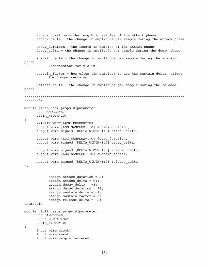
attack_duration - the length in samples of the attack phaseattack_delta - the change in amplitude per sample during the attack phase
decay_duration - the length in samples of the attack phasedecay_delta - the change in amplitude per sample during the decay phase
sustain_delta - the change in amplitude per sample during the sustain phase
(nonconstant for violin)
sustain_factor - how often (in samples) to use the sustain delta, allows for longer sustains
release_delta - the change in amplitude per sample during the release phase
--------------------------------------------------------------------------------------*/
module piano_asdr_props #(parameterLOG_SAMPLES=8,DELTA_WIDTH=10)
(//INSTRUMENT ADSR PROPERTIESoutput wire [LOG_SAMPLES-1:0] attack_duration,output wire signed [DELTA_WIDTH-1:0] attack_delta,
output wire [LOG_SAMPLES-1:0] decay_duration,output wire signed [DELTA_WIDTH-1:0] decay_delta,
output wire signed [DELTA_WIDTH-1:0] sustain_delta,output wire [LOG_SAMPLES-1:0] sustain_factor,
output wire signed [DELTA_WIDTH-1:0] release_delta);
assign attack_duration = 8;assign attack_delta = 64;assign decay_delta = -5;assign decay_duration = 39;assign sustain_delta = -1;assign sustain_factor = 2;assign release_delta = -2;
endmodule
module violin_asdr_props #(parameterLOG_SAMPLES=8,LOG_NUM_TRACKS=1,DELTA_WIDTH=10)
(input wire clock,input wire reset,input wire sample_increment,
164

//INSTRUMENT ADSR PROPERTIESoutput wire [LOG_SAMPLES-1:0] attack_duration,output wire signed [DELTA_WIDTH-1:0] attack_delta,
output wire [LOG_SAMPLES-1:0] decay_duration,output wire signed [DELTA_WIDTH-1:0] decay_delta,
output wire signed [DELTA_WIDTH-1:0] sustain_delta,output wire [LOG_SAMPLES-1:0] sustain_factor,
output wire signed [DELTA_WIDTH-1:0] release_delta);
wire reverse;wire [LOG_SAMPLES-1:0] sample_count;
wire signed [DELTA_WIDTH-1:0] delta_offset, delta_flux;
overflow_counter #(.COUNT_WIDTH(LOG_SAMPLES),.MAX_COUNT(31))
reverser (.clock(clock),.increment(sample_increment),.restart(reset),
.count(sample_count),
.overflow(reverse));
violin_flux #(.LOG_SAMPLES(LOG_SAMPLES),.DELTA_WIDTH(DELTA_WIDTH))
vf (.sample_count(sample_count),.delta_flux(delta_flux)
);
assign attack_duration = 18;assign decay_duration = 0;assign sustain_factor = 2;
assign attack_delta = 20;assign decay_delta = 0;assign sustain_delta = delta_flux;assign release_delta = -54;
endmodule
module whistle_asdr_props #(parameterLOG_SAMPLES=8,DELTA_WIDTH=10)
(
165

//INSTRUMENT ADSR PROPERTIESoutput wire [LOG_SAMPLES-1:0] attack_duration,output wire signed [DELTA_WIDTH-1:0] attack_delta,
output wire [LOG_SAMPLES-1:0] decay_duration,output wire signed [DELTA_WIDTH-1:0] decay_delta,
output wire signed [DELTA_WIDTH-1:0] sustain_delta,output wire [LOG_SAMPLES-1:0] sustain_factor,
output wire signed [DELTA_WIDTH-1:0] release_delta);
assign attack_duration = 38;assign attack_delta = 13;assign decay_delta = -1;assign decay_duration = 5;assign sustain_delta = 0;assign sustain_factor = 0;assign release_delta = -18;
endmodule
//ROM containing the notes for Mary Had A Little Lambmodule little_lamb_sheet ( input wire [3:0] index, output reg signed [15:0] beat_info); always @(index) case (index)
// 16'bXX_EE_DD_CC_BB_AA_GG_FF4'd0: beat_info = 16'b00_00_00_00_00_00_11_00;4'd1: beat_info = 16'b10_11_00_00_00_00_00_00;4'd2: beat_info = 16'b00_00_00_00_00_01_00_00;4'd3: beat_info = 16'b00_00_00_00_01_00_00_00;4'd4: beat_info = 16'b00_00_00_01_00_00_00_00;4'd5: beat_info = 16'b00_00_00_01_00_00_00_00;4'd6: beat_info = 16'b00_00_00_10_00_00_00_00;4'd7: beat_info = 16'b10_00_00_00_00_00_00_00;4'd8: beat_info = 16'b00_00_00_00_01_00_00_00;4'd9: beat_info = 16'b00_00_00_00_01_00_00_00;4'd10: beat_info = 16'b00_00_00_00_10_00_00_00;4'd11: beat_info = 16'b00_00_00_00_00_00_00_00;4'd12: beat_info = 16'b00_00_00_01_00_00_00_00;4'd13: beat_info = 16'b00_01_00_00_00_00_00_00;4'd14: beat_info = 16'b00_10_00_00_00_00_00_00;4'd15: beat_info = 16'b11_00_00_00_00_00_00_00;default: beat_info = 16'b00_00_00_00_00_00_00_00;
endcaseendmodule
166

//defines simple sinusoidal oscillation during the sustain phase for the violin and cellomodule violin_flux #(parameter
LOG_SAMPLES=8,DELTA_WIDTH=10)
(input wire [7:0] sample_count,output reg signed [DELTA_WIDTH-1:0] delta_flux
);wire [4:0] index = sample_count[4:0];always @(index)
case (index)0: delta_flux = -25;1: delta_flux = -25;2: delta_flux = -23;3: delta_flux = -21;4: delta_flux = -18;5: delta_flux = -14;6: delta_flux = -10;7: delta_flux = -5;8: delta_flux = 0;9: delta_flux = 5;10: delta_flux = 10;11: delta_flux = 14;12: delta_flux = 18;13: delta_flux = 21;14: delta_flux = 23;15: delta_flux = 25;16: delta_flux = 25;17: delta_flux = 25;18: delta_flux = 23;19: delta_flux = 21;20: delta_flux = 18;21: delta_flux = 14;22: delta_flux = 10;23: delta_flux = 5;24: delta_flux = 0;25: delta_flux = -5;26: delta_flux = -10;27: delta_flux = -14;28: delta_flux = -18;29: delta_flux = -21;30: delta_flux = -23;31: delta_flux = -25;
endcase
endmodule
audio_gen_player.v/*--------------------------------------------------------------------------------------Module: key_state_memoryX
167

Description:Stores the key press states for all the keys and manages updates from the
player modules.
Parameters:Defined in Audio Generator Module
Inputs:See below
Outputs:See below
--------------------------------------------------------------------------------------*/
module key_state_memoryX #(parameterLOG_INSTRUMENTS=1,LOG_NOTES=4,LOG_OCTAVES=3)
(input wire clock,input wire reset,
//read_enable indicates when the module is being read, so it can tell the players to
//cease writinginput wire read_enable,//read indices specifying the key whose key press state is neededinput wire [LOG_NOTES-1:0] read_note_index,input wire [LOG_OCTAVES-1:0] read_octave_index,
//inputs from player moudlesinput wire write_enable,input wire [LOG_NOTES-1:0] write_note_index,input wire [LOG_OCTAVES-1:0] write_octave_index,input wire [LOG_INSTRUMENTS-1:0] write_instrument_index,input wire write_key_pressed,
//indicates that the module is writableoutput wire writable,
//the keys being pressed by the instruments (for the key specified by the read indices)
output wire [(1<<LOG_INSTRUMENTS)-1:0] keys_pressed_out);
localparam NUM_INSTRUMENTS = (1<<LOG_INSTRUMENTS);localparam INDEX_WIDTH = LOG_OCTAVES+LOG_NOTES;
//index signalswire [INDEX_WIDTH-1:0] index, read_index, write_index;reg [INDEX_WIDTH-1:0] delayed_write_index;
168
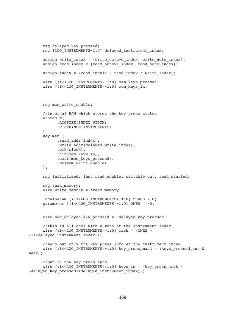
reg delayed_key_pressed;reg [LOG_INSTRUMENTS-1:0] delayed_instrument_index;
assign write_index = {write_octave_index, write_note_index};assign read_index = {read_octave_index, read_note_index};
assign index = (read_enable ? read_index : write_index);
wire [(1<<LOG_INSTRUMENTS)-1:0] mem_keys_pressed;wire [(1<<LOG_INSTRUMENTS)-1:0] mem_keys_in;
reg mem_write_enable;
//internal RAM which stores the key press stateswrbram #(
.LOGSIZE(INDEX_WIDTH),
.WIDTH(NUM_INSTRUMENTS))key_mem (
.read_addr(index),
.write_addr(delayed_write_index),
.clk(clock),
.din(mem_keys_in),
.dout(mem_keys_pressed),
.we(mem_write_enable));
reg initialized, last_read_enable, writable_out, read_started;
reg read_memory;wire write_memory = !read_memory;
localparam [(1<<LOG_INSTRUMENTS)-1:0] ZEROS = 0;parameter [(1<<LOG_INSTRUMENTS)-1:0] ONES = ~0;
wire neg_delayed_key_pressed = ~delayed_key_pressed;
//this is all ones with a zero at the instrument indexwire [(1<<LOG_INSTRUMENTS)-1:0] mask = (ONES ^
(1<<delayed_instrument_index));
//zero out only the key press info at the instrument indexwire [(1<<LOG_INSTRUMENTS)-1:0] key_press_mask = (keys_pressed_out &
mask);
//put in new key press infowire [(1<<LOG_INSTRUMENTS)-1:0] keys_in = (key_press_mask |
(delayed_key_pressed<<delayed_instrument_index));
169
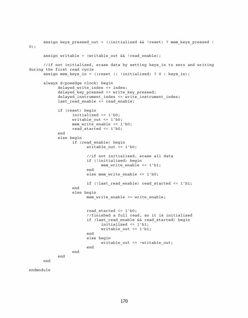
assign keys_pressed_out = ((initialized && !reset) ? mem_keys_pressed : 0);
assign writable = (writable_out && !read_enable);
//if not initialized, erase data by setting keys_in to zero and writing during the first read cycle
assign mem_keys_in = ((reset || !initialized) ? 0 : keys_in);
always @(posedge clock) begindelayed_write_index <= index;delayed_key_pressed <= write_key_pressed;delayed_instrument_index <= write_instrument_index;last_read_enable <= read_enable;
if (reset) begininitialized <= 1'b0;writable_out <= 1'b0;mem_write_enable <= 1'b0;read_started <= 1'b0;
endelse begin
if (read_enable) beginwritable_out <= 1'b0;
//if not initialized, erase all dataif (!initialized) begin
mem_write_enable <= 1'b1;endelse mem_write_enable <= 1'b0;
if (!last_read_enable) read_started <= 1'b1;endelse begin
mem_write_enable <= write_enable;
read_started <= 1'b0;//finished a full read, so it is initializedif (last_read_enable && read_started) begin
initialized <= 1'b1;writable_out <= 1'b1;
endelse begin
writable_out <= ~writable_out;end
endend
end
endmodule
170

/*--------------------------------------------------------------------------------------Module: sheet_playerDescription:
Plays back sheet music in a 16 bit format. The lower 14 bits represent 7 notes (quarter,
half, or whole).
Parameters:Defined in Audio Generator Module
Inputs:See below
Outputs:See below
--------------------------------------------------------------------------------------*/
module sheet_player #(parameterSHEET_ADDR_WIDTH=4,SHEET_DATA_WIDTH=16,NOTE_INFO_WIDTH=2,
//LOG_TICKS=11,
QRT_DURATION=128,
LAST_OCTAVE=7,
LOG_INSTRUMENTS=1,LOG_SAMPLES=8,LOG_NOTES=4,LOG_OCTAVES=3,LOG_HARMONICS=3)
(input wire clock,
//resets the modules stateinput wire reset,
//enable signal for the moduleinput wire enable_in,
//specifies next beat switches to next beat's notesinput wire beat_enable,
//specifies next sample, indicates when the note should beat//turned off in conjunction with the DURATION parameter which//is given in terms of samplesinput wire sample_enable,
171

//this module can only play one octave from one instrument at a time//this selects which octave and instrument to useinput wire [LOG_OCTAVES-1:0] octave_index,input wire [LOG_INSTRUMENTS-1:0] instrument_index,
input wire [SHEET_DATA_WIDTH-1:0] sheet_data,output reg [SHEET_ADDR_WIDTH-1:0] sheet_address,output reg send_new_address,
//indicates that the module has finished playbackoutput reg done_playing,
//OUTPUTS TO KEY PRESS MEMORYoutput reg [LOG_NOTES-1:0] write_note_index,output reg [LOG_OCTAVES-1:0] write_octave_index,output reg [LOG_INSTRUMENTS-1:0] write_instrument_index,output reg key_pressed,output reg key_press_we
);reg [SHEET_DATA_WIDTH-1:0] current_sheet_data;
//note info parameterslocalparam [NOTE_INFO_WIDTH-1:0] NONE = 0;localparam [NOTE_INFO_WIDTH-1:0] QUARTER = 1;localparam [NOTE_INFO_WIDTH-1:0] HALF = 2;localparam [NOTE_INFO_WIDTH-1:0] WHOLE = 3;
//note name parameterslocalparam [LOG_NOTES-1:0] F = 5;localparam [LOG_NOTES-1:0] G = 7;localparam [LOG_NOTES-1:0] A = 9;localparam [LOG_NOTES-1:0] B = 11;localparam [LOG_NOTES-1:0] C = 0;localparam [LOG_NOTES-1:0] D = 2;localparam [LOG_NOTES-1:0] E = 4;
wire last_beat_flag = sheet_data[SHEET_DATA_WIDTH-1];
//can't support some notes in the last octavewire [LOG_OCTAVES-1:0] base_octave = ((octave_index == LAST_OCTAVE) ?
(octave_index - 1) : octave_index);
reg [2:0] current_note;reg [3:0] current_note_offset;wire [NOTE_INFO_WIDTH-1:0] current_note_info =
(sheet_data>>current_note_offset);
localparam NOTE_STATE_WIDTH = 3;wire [NOTE_STATE_WIDTH-1:0] note_info_state = ((current_note_info ==
WHOLE) ? 4 : {1'b0, current_note_info});
reg [20:0] note_states;
172

reg [4:0] note_state_offset;wire [NOTE_STATE_WIDTH-1:0] current_note_state =
(note_states>>note_state_offset);
reg [NOTE_STATE_WIDTH-1:0] new_note_state;localparam [NOTE_STATE_WIDTH-1:0] NONE_STATE = 0;localparam [NOTE_STATE_WIDTH-1:0] QUARTER_STATE = 1;localparam [NOTE_STATE_WIDTH-1:0] HALF_STATE = 2;localparam [NOTE_STATE_WIDTH-1:0] THREE_STATE = 3;localparam [NOTE_STATE_WIDTH-1:0] WHOLE_STATE = 4;
wire release_quarter_notes;reg release_signal;
wire [LOG_SAMPLES-1:0] sample_count;
overflow_counter #(.COUNT_WIDTH(LOG_SAMPLES),.MAX_COUNT(QRT_DURATION-1))
sample_counter (.clock(clock),.increment(sample_enable),.restart(beat_enable || reset),
.count(sample_count),
.overflow(release_quarter_notes));
reg [LOG_NOTES-1:0] current_note_index;reg [LOG_OCTAVES-1:0] current_octave;
always @* begincase (current_note)
3'd0: current_note_index = F;3'd1: current_note_index = G;3'd2: current_note_index = A;3'd3: current_note_index = B;3'd4: current_note_index = C;3'd5: current_note_index = D;3'd6: current_note_index = E;default: current_note_index = 0;
endcase
case (current_note)3'd0: current_octave = base_octave;3'd1: current_octave = base_octave;3'd2: current_octave = base_octave;3'd3: current_octave = base_octave;3'd4: current_octave = base_octave + 1;3'd5: current_octave = base_octave + 1;3'd6: current_octave = base_octave + 1;default: current_octave = 0;
173
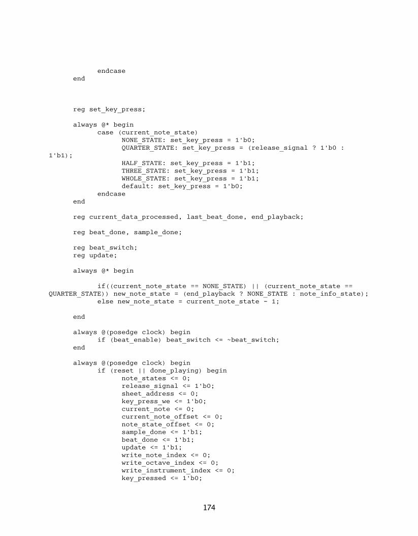
endcaseend
reg set_key_press;
always @* begincase (current_note_state)
NONE_STATE: set_key_press = 1'b0;QUARTER_STATE: set_key_press = (release_signal ? 1'b0 :
1'b1);HALF_STATE: set_key_press = 1'b1;THREE_STATE: set_key_press = 1'b1;WHOLE_STATE: set_key_press = 1'b1;default: set_key_press = 1'b0;
endcaseend
reg current_data_processed, last_beat_done, end_playback;
reg beat_done, sample_done;
reg beat_switch;reg update;
always @* begin
if((current_note_state == NONE_STATE) || (current_note_state == QUARTER_STATE)) new_note_state = (end_playback ? NONE_STATE : note_info_state);
else new_note_state = current_note_state - 1;
end
always @(posedge clock) beginif (beat_enable) beat_switch <= ~beat_switch;
end
always @(posedge clock) beginif (reset || done_playing) begin
note_states <= 0;release_signal <= 1'b0;sheet_address <= 0;key_press_we <= 1'b0;current_note <= 0;current_note_offset <= 0;note_state_offset <= 0;sample_done <= 1'b1;beat_done <= 1'b1;update <= 1'b1;write_note_index <= 0;write_octave_index <= 0;write_instrument_index <= 0;key_pressed <= 1'b0;
174

end_playback <= 1'b0;//sheet_data <= 1'b0;last_beat_done <= 1'b0;if (reset) done_playing <= 1'b0;
endelse begin
last_beat_done <= beat_done;
if (release_quarter_notes) release_signal <= 1'b1;else if (!last_beat_done && beat_done) release_signal <=
1'b0;
if (beat_enable) beginbeat_done <= 1'b0;
end
if (sample_enable) beginsample_done <= 1'b0;current_note <= 0;current_note_offset <= 0;note_state_offset <= 0;
endelse begin
if (enable_in) beginif (current_note != 7) begin
if (!sample_done) begin//write note information every samplewrite_note_index <=
current_note_index;write_octave_index <= current_octave;write_instrument_index <=
instrument_index;key_pressed <= set_key_press;key_press_we <= 1'b1;
endelse begin
key_press_we <= 1'b0;end
//if notes shouldn't change on next beat, don't update
if((current_note_state != NONE_STATE) && (current_note_state != QUARTER_STATE)) update <= 1'b0;
//on the beat, update the note informationif (!beat_done && update) begin
case(current_note)0: note_states[2:0] <=
new_note_state;1: note_states[5:3] <=
new_note_state;
175

2: note_states[8:6] <= new_note_state;
3: note_states[11:9] <= new_note_state;
4: note_states[14:12] <= new_note_state;
5: note_states[17:15] <= new_note_state;
6: note_states[20:18] <= new_note_state;
endcaseendelse begin
end
note_state_offset <= note_state_offset + NOTE_STATE_WIDTH;
current_note_offset <= current_note_offset + NOTE_INFO_WIDTH;
current_note <= current_note + 1;endelse begin
update <= 1'b1;if (!beat_done && update) begin
end_playback <= (last_beat_flag || (&sheet_address));
if (end_playback) beginsheet_address <= 0;done_playing <= 1'b1;
endelse begin
sheet_address <= sheet_address + 1;
endend
key_press_we <= 1'b0;sample_done <= 1'b1;beat_done <= 1'b1;
endendelse begin
key_press_we <= 1'b0;end
endend
end
endmodule
176

/*--------------------------------------------------------------------------------------Module: event_playerDescription:
Plays back a transformed MIDI song from a ROM.
Parameters:Defined in Audio Generator Module
Inputs:See below
Outputs:See below
--------------------------------------------------------------------------------------*/
module event_player #(parameterEVENT_ADDR_WIDTH=11,EVENT_DATA_WIDTH=21,LOG_TICKS=11,LOG_TICKS_PER_SECOND=3,NUM_PULSES=48000,
LOG_INSTRUMENTS=1,PRECISION_WIDTH=16,LOG_NOTES=4,LOG_OCTAVES=3,LOG_HARMONICS=3)
(input wire clock,
//resets the modules stateinput wire reset,
//enable signal, tells this module it can process information and write to the key state RAM
input wire enable,
//play signal (only increments counter if playing, otherwise it is paused).
input wire play,
//ready pulse (tells it to increment the counter which gives it the tick count)
input wire ready,
//indicates that the module has completed playbackoutput reg done_playing,
//OUTPUTS TO KEY PRESS MEMORYoutput reg [LOG_NOTES-1:0] write_note_index,
177
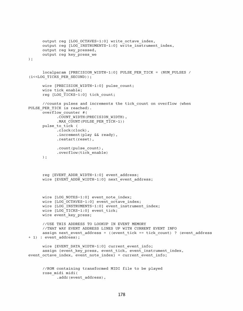
output reg [LOG_OCTAVES-1:0] write_octave_index,output reg [LOG_INSTRUMENTS-1:0] write_instrument_index,output reg key_pressed,output reg key_press_we
);
localparam [PRECISION_WIDTH-1:0] PULSE_PER_TICK = (NUM_PULSES / (1<<LOG_TICKS_PER_SECOND));
wire [PRECISION_WIDTH-1:0] pulse_count;wire tick_enable;reg [LOG_TICKS-1:0] tick_count;
//counts pulses and increments the tick_count on overflow (when PULSE_PER_TICK is reached).
overflow_counter #(.COUNT_WIDTH(PRECISION_WIDTH),.MAX_COUNT(PULSE_PER_TICK-1))
pulse_to_tick (.clock(clock),.increment(play && ready),.restart(reset),
.count(pulse_count),
.overflow(tick_enable));
reg [EVENT_ADDR_WIDTH-1:0] event_address;wire [EVENT_ADDR_WIDTH-1:0] next_event_address;
wire [LOG_NOTES-1:0] event_note_index;wire [LOG_OCTAVES-1:0] event_octave_index;wire [LOG_INSTRUMENTS-1:0] event_instrument_index;wire [LOG_TICKS-1:0] event_tick;wire event_key_press;
//USE THIS ADDRESS TO LOOKUP IN EVENT MEMORY//THAT WAY EVENT ADDRESS LINES UP WITH CURRENT EVENT INFOassign next_event_address = ((event_tick == tick_count) ? (event_address
+ 1) : event_address);
wire [EVENT_DATA_WIDTH-1:0] current_event_info;assign {event_key_press, event_tick, event_instrument_index,
event_octave_index, event_note_index} = current_event_info;
//ROM containing transformed MIDI file to be playedrose_midi midi(
.addr(event_address),
178

.clk(clock),
.dout(current_event_info));
always @(posedge clock) beginif (reset || done_playing) begin
event_address <= 0;key_press_we <= 1'b0;tick_count <= 0;if (reset) done_playing <= 1'b0;
endelse begin
if (play && tick_enable) tick_count <= tick_count + 1;
//if enable signal is sent, and the module isn't done playing track
//process track informationif (enable && !done_playing) begin
if (current_event_info != 0) beginif (event_tick == tick_count) begin
//go to next eventevent_address <= next_event_address;
//if at last address (event address is all ones)
//the module is done playingif (&event_address) done_playing <= 1'b1;
//write note informationwrite_note_index <= event_note_index;write_octave_index <= event_octave_index;write_instrument_index <=
event_instrument_index;key_pressed <= event_key_press;key_press_we <= 1'b1;
endelse key_press_we <= 1'b0;
end//all current_event_info = 0, means reached end of
track//reset all signalselse begin
done_playing <= 1'b1;event_address <= 0;//don't output key press info if at empty slotkey_press_we <= 1'b0;
endend
else begin
//don't output key press info if not enabled or done_playing
179

key_press_we <= 1'b0;
endend
end
endmodule
audio_gen_utils.v
/*--------------------------------------------------------------------------------------Module: overflow_counterDescription:
Counts up to a particular maximum value and restarts. When the maximum value is reached,
the counter outputs an overflow signal on the next clock cycle after restarting at
zero.
Parameters:COUNT_WIDTH - the width in bits of the countMAX_COUNT - the maximum value that the counter can reach before
restarting
Inputs:clock - the clock pulse (27 MHz)increment - when high, the counter increments on the next clock cyclerestart - when high, the count is set to zero and overflow goes low.
Outputs:count - the current count (0 to MAX_COUNT)overflow - (pulse) set high when the counter iterates through all numbers
between 0 and MAX_COUNT
Notes:1. Make sure MAX_COUNT is within the range of numbers possible given
COUNT_WIDTH, otherwise, there will never be overflow.
--------------------------------------------------------------------------------------*/
module overflow_counter #(parameterCOUNT_WIDTH=0,MAX_COUNT=0)
(input wire clock,input wire increment,input wire restart,
180
output reg [COUNT_WIDTH-1:0] count,output reg overflow
);
always @* beginif (increment && (count == MAX_COUNT)) overflow = 1'b1;else overflow = 1'b0;
end
always @(posedge clock) begin//restart, so set count to zero and set overflow low.if (restart) begin
count <= 0;endelse begin
//increment the countif (increment) begin
//restart if MAX_COUNT is reached, and set the overflow high
if (count == MAX_COUNT) begincount <= 0;
end//otherwise, just increment. overflow is lowelse begin
count <= count + 1;end
end
//overflow is only set high if iterating (aka increment is high)
else begin//enable_overflow <= 1'b0;
endend
endendmodule
//interpolates using the delta per sample and the number of pulses//converts the delta to a delta per pulse (INCREASE_UNIT) and uses that to //increase the value (has precision bits to allow for higher granularity)module interpolator #(parameter
LOG_SAMPLES=8,NUM_PULSES=48000,DELTA_WIDTH=8,PRECISION_WIDTH=8)
(input wire signed [DELTA_WIDTH-1:0] delta,input wire [DELTA_WIDTH+PRECISION_WIDTH-1:0] data_in,
output wire [DELTA_WIDTH+PRECISION_WIDTH-1:0] data_out);
localparam DATA_WIDTH = PRECISION_WIDTH + DELTA_WIDTH;
181

localparam [PRECISION_WIDTH-1:0] PULSE_PER_SAMPLE = (NUM_PULSES / (1<<LOG_SAMPLES));
localparam [PRECISION_WIDTH-1:0] ZERO = 0;localparam signed [PRECISION_WIDTH:0] INCREASE_UNIT =
(((1<<LOG_SAMPLES)*(1<<PRECISION_WIDTH))/NUM_PULSES);
wire signed [DATA_WIDTH:0] increase = delta * INCREASE_UNIT;wire signed [DATA_WIDTH:0] signed_data = {1'b0, data_in};wire signed [DATA_WIDTH:0] result = data_in + increase;
assign data_out = (result[DATA_WIDTH] ? 0 : result[DATA_WIDTH-1:0]); //assign data_out = data_in + increase;
endmodule
//adds a value to another value but when the value goes over the MAX value,//MAX is outputmodule max_adder #(parameter
DATA_WIDTH=8,MAX=(1<<(DATA_WIDTH-1)))
(input wire [DATA_WIDTH-1:0] data,input wire signed [DATA_WIDTH-1:0] delta,
output reg [DATA_WIDTH-1:0] result);
wire signed [DATA_WIDTH:0] signed_data = {1'b0, data};wire signed [DATA_WIDTH:0] sum = signed_data + delta;
//parameter [DATA_WIDTH-1:0] MAX = (1<<(DATA_WIDTH-1));
always @* beginif (sum > MAX) result = MAX;else if (sum < 0) result = 0;else result = sum[DATA_WIDTH-1:0];
end
endmodule
//parameterized dual port (one read port, one write port) module //modified version of mybram from lab4module wrbram #(parameter
LOGSIZE=14,WIDTH=1)
(input wire [LOGSIZE-1:0] read_addr,input wire [LOGSIZE-1:0] write_addr,input wire clk,input wire [WIDTH-1:0] din,output reg [WIDTH-1:0] dout,input wire we
); // let the tools infer the right number of BRAMs
182

(* ram_style = "block" *) reg [WIDTH-1:0] mem[(1<<LOGSIZE)-1:0]; always @(posedge clk) begin if (we) mem[write_addr] <= din; dout <= mem[read_addr]; end
//INITinteger i;initial begin
for (i = 0; i < (1<<LOGSIZE); i = i+1) beginmem[i] = 0;
endend
endmodule
//parameterized single port BRAM module taken from lab4module mybram #(parameter LOGSIZE=14, WIDTH=1) (input wire [LOGSIZE-1:0] addr, input wire clk, input wire [WIDTH-1:0] din, output reg [WIDTH-1:0] dout, input wire we); // let the tools infer the right number of BRAMs (* ram_style = "block" *) reg [WIDTH-1:0] mem[(1<<LOGSIZE)-1:0]; always @(posedge clk) begin if (we) mem[addr] <= din; dout <= mem[addr]; end
//INITinteger i;initial begin
for (i = 0; i < (1<<LOGSIZE); i = i+1) beginmem[i] = 0;
endend
endmodule
//scales a signed value by the given scale factormodule scaler #(parameter
DATA_WIDTH=18,SCALE_WIDTH =8)
(input wire clock,input wire reset,input wire enable,input wire signed [DATA_WIDTH-1:0] data,input wire [SCALE_WIDTH-1:0] factor,
183
output reg [DATA_WIDTH-1:0] product);
//factor converted to signed positive value)wire signed [SCALE_WIDTH:0] signed_factor = {1'b0, factor};
//multiply by factor (factor converted to signed positive value)wire signed [SCALE_WIDTH+DATA_WIDTH:0] mult = data * signed_factor;
//divide by 2^(SCALE_WIDTH-1)wire signed [SCALE_WIDTH+DATA_WIDTH:0] shift = mult >>> SCALE_WIDTH-1;always @* begin
if (reset || !enable) beginproduct = 0;
endelse begin
if (factor[SCALE_WIDTH-1]) beginproduct = data;
endelse begin
product = shift[DATA_WIDTH-1:0];end
endend
endmodule
//scales a unsigned value by the given scale factormodule positive_scaler #(parameter
DATA_WIDTH=18,SCALE_WIDTH =8)
(input wire clock,input wire reset,input wire enable,
//the data, converted to unsigned format internallyinput wire [DATA_WIDTH-1:0] data,
//the scale factorinput wire [SCALE_WIDTH-1:0] factor,
output wire [DATA_WIDTH-1:0] product);
wire [DATA_WIDTH:0] temp;assign product = temp[DATA_WIDTH-1:0];
scaler #(//parameters.DATA_WIDTH(DATA_WIDTH+1),.SCALE_WIDTH(SCALE_WIDTH)
)
184

note_amp_calc (//inputs.clock(clock),.reset(reset),.enable(enable),.data({1'b0, data}),.factor(factor),
//outputs.product(temp)
);endmodule
// parameterized 2 to 1 muxmodule mux2 #(parameter
W=1) // data width, default 1 bit(
input [W-1:0] a,b,input sel,output [W-1:0] z
);assign z = sel ? b : a;
endmodule
185