pfh05w evaluation test board - mouser.jp
TRANSCRIPT

TDK-Lambda Americas Inc. 2018
1
PFH05W Evaluation
Test BoardApplication notes
Version 1.0

TDK-Lambda Americas Inc. 2018
2
Table of ContentsBEFORE USING THE POWER SUPPLY UNIT .................................................. Error! Bookmark not defined.
1.0 Getting Started ............................................................................................................................ 5
1.1 Test Equipment........................................................................................................................ 6
1.2 Test Setup ................................................................................................................................ 7
1.3 Test Points ............................................................................................................................... 9
1.4 PMBus and Remote On/Off Functions .................................................................................... 10
1.5 Setting the PMBus Address .................................................................................................... 11
1.6 Turning PFH Module On/Off................................................................................................... 12
2.0 Electrical Schematic Drawing ..................................................................................................... 13
3.0 Bill of Material ........................................................................................................................... 14
4.0 Board Files ................................................................................................................................. 15
5.0 EMI Conducted Test Results....................................................................................................... 22

TDK-Lambda Americas Inc. 2018
3
BEFORE USING THE POWER SUPPLY UNIT
Be sure to read and understand this instruction manual thoroughly before using this product. Pay attention to all cautions and warnings before
using this product. Incorrect usage could lead to an electrical shock, damage to the unit or a fire hazard.
DANGER
Never use this product in locations where flammable gas or ignitable substances are present. There are risks of igniting these substances and
exploding by arcing.
WARNING
Do not touch this product or its internal components while circuit is live, or shortly after shut down. There may be high voltage or hightemperature present and you may receive an electric shock or burn.
While this product is operating, keep your hands and face away from it as you may be injured by an unexpected situation.
Do not make unauthorized changes to this product, otherwise you may receive an electric shock and void your warranty.
Do not drop or insert anything into the product. It might lead to a failure, fire or electric shock.
Do not use this product if abnormal conditions such as emission of smoke and/or abnormal smell or audible noise, etc… are present. It might
lead to fire and/or electric shock. In such cases, please contact TDK Lambda. Do not attempt repair by yourself, as it is dangerous for the user.
Do not operate these products in the presence of condensation. It might lead to fire or electric shock.
CAUTION
This power supply is designed and manufactured for use within an end product such that it is accessible only to trained SERVICE ENGINEERS.
Confirm that the connections to input/output terminals, and signal terminals are correct as specified in this instruction manual before turning
on the power.
Input voltage, Output current, Output power, ambient temperature, case temperature, and ambient humidity should be kept within thespecifications, otherwise the product may be damaged.
Do not operate and store this product in an environment where condensation might occur. In such case, waterproof treatment is necessary.
The equipment has been evaluated for use in a Pollution Degree 2 environment.
Do not use this product in environment with a strong electromagnetic field, corrosive gas or conductive substances.
For applications, which require very high reliability, such as nuclear related equipment, medical equipment, traffic control equipment, etc.,
it is necessary to provide a fail-safe mechanism in the end equipment.
Do not inject abnormal voltages into the output terminal or signal terminal of this product. The injection of reverse voltage or over voltageexceeding nominal output voltage into the output terminal or signal terminal might cause damage to internal components.
Never operate the product under the over-current or short circuit conditions. Failure or other damage may occur.
The output voltage of this power supply unit is considered to be a hazardous energy level (The voltage is 2V or more and the electric poweris 240W or more). It must not be made accessible to users. Protection must be provided for Service Engineers against indirect contact withthe output terminals and/or to prevent tools being dropped across them. While working on this product, the AC input power must be switchedoff, and the input, output, +VBus, and -VBus terminal voltages should be at a safe level.
The application circuits and their parameters are for reference only. Be sure to verify effectiveness of these circuits and their parametersbefore finalizing the circuit design.
Use a Fast-Blow external fuse to each module to ensure safe operation and compliance with the safety standards to which it is approved. Therecommended input fuse rating within the instructions is as follows: 10A, 250V fast acting fuse. The breaking capacity and voltage rating ofthis fuse may be subject to the end use application.

TDK-Lambda Americas Inc. 2018
4
Reference Documents:
1.) PFH Instruction Manual
2.) PFH PMBus Specification Customer Release
CAUTION
This information in this document is subject to change without prior notice. Please refer to the latest version of the data sheet, etc., for themost up-to date specifications of the product.
No part of this document may be copied or reproduced in any form without prior written consent TDK-Lambda.

TDK-Lambda Americas Inc. 2018
5
1.0 Getting Started
PFH05W##-100-EVK-S1 & PFH05W##-1D0-EVK-S1 Evaluation Boards
PFH05W-001-EVK-S0 Evaluation Board

TDK-Lambda Americas Inc. 2018
6
1.1 Test Equipment
1.) AC Voltage Source: capable of single-phase output AC voltage 85 VAC to 265 VAC, 47 Hz to 63Hz1, adjustable, with minimum power rating 500 W, the AC voltage source to be used shouldmeet IEC60950 reinforced insulation requirement.
NOTE: 1. Input frequency above 63Hz, refer to PFH Datasheet
2.) DC Multimeter: capable of 0V to 500V input range.
3.) Output Load: DC load capable of 60 VDC or greater, DC Load current up to 42A or greater(12V/42A, 28V/18A, or 48V/10.5A), and 500 W or greater, with display such as load current andload power.
4.) Fan: 200 LFM to 400 LFM forced air cooling is recommended, but not a must.

TDK-Lambda Americas Inc. 2018
7
1.2 Test Setup
1.) Electrical Input Connections: CONN1: LINE, Input Line Connection
CONN2: NEUT, Input Neutral Connection
CONN3: EGND, Earth Ground Connection
NOTE: Refer to the PFH Datasheet for specific module’s AC Input Current
requirement when sizing wire gauge and cable length.
2.) Electrical Output Connection: CONN5 +Vout, Output Load Connections
(Red Cable)
CONN4 -Vout, Output Load Return Connections
(Black Cable)

TDK-Lambda Americas Inc. 2018
8
WARNING
Make sure ALL input and output cables are de-energized before making electrical connections to the
Evaluation Test Board

TDK-Lambda Americas Inc. 2018
9
1.3 Test Points
1.) Secondary Test Points: TP201 Vout+, Monitor Output Voltage
TP204 Vout(-), Monitor Output Voltage return
TP202 RS(+), Output Remote Sense (+) connection
TP203 TRIM, Trim Test connection
WARNING HAZARDOUS VOLTAGE
2.) Primary Test Points: TP103 +BUS, Monitor 400Vdc
TP104 -BUS, Monitor 400Vdc return
TP101 LINE, Monitor AC Line Input
TP102 NEUT, Monitor AC Neutral Input

TDK-Lambda Americas Inc. 2018
10
1.4 PMBus and Remote On/Off Functions
1.) PMBus Connections (J301)
NOTE: NOTE: J301 is compatible with TI USB Interface Adapter EVM (Evaluation Module), TI part #: USB-
TO-GPIO. This adapter is available from,
TI
Digi-Key
Newark Element
Mouser Electronics
Arrow
Texas Instruments offers a Free SMBus tool in their FUSION DIGITAL POWER STUDIO that allows the user
to send and read PMBus commands to and from the module.
http://www.ti.com/tool/FUSION-DIGITAL-POWER-STUDIO
FUSION DIGITAL POWER STUDIO System Requirements
• Window-Based application, support Window XP and Window 7
• Design, Configure & monitor TI digital power controllers and sequencers/health monitors using TI USB
Adapter
• Support multiple devices in the same bus in Online (connected to live devices), Offline (file-base virtual
devices), and Hybrid mode (mix of online & offline)
• Support exporting device’s configuration to different files formats for 3rd party programming
• Support Command Line Tools for scripting & automation
Pin #: Description:
1 Not Used
2 Not Used
3 Not Used
4 Not Used
5 USB 3.3Vdc
6 SGND
7 Not Used
8 PMBus Alert
9 PMBus Clock
10 PMBus Data

TDK-Lambda Americas Inc. 2018
11
WARNING When AC voltage is applied to the Evaluation Test Board the 450V bulk capacitors ARE
energized at ALL time
2.) Remote On/Off (SW200) SW200, Will either turn the module On or put it into Standby
3.) Auxiliary Voltage (DS301) DS301, The LED will Turn-On when the 450Vdc bulk capacitors
are energized above 70Vdc
4.) Power Good (DS300) DS300, The LED will Turn-On once the module’s output has
been Turned-On
5.) Test Points TP301 Monitor Auxiliary Voltage
TP302 Monitor Power Good Signal
1.5 Setting the PMBus Address
The PMBus address setting on the Evaluation Test Board comes with the Factory default setting,
Address: 0x58 (Hex) (R318 & R319 are not populated)
To change PMBus address to a different address R318 (AD1) and R319 (AD2) must be populated
with appropriate resistor values located in “PFH PMBus Specification Customer Release”
document.
Example: Suppose a PMBus address of 0x51 was desired instead of 0x58.
R318 (PMBus AD1): Not Populated Populate with 14K (0805 Resistor)
R319 (PMBus AD2): Not Populated Populate with 69.8K (0805 Resistor)

TDK-Lambda Americas Inc. 2018
12
1.6 Turning PFH Module On/Off
1.) Before applying AC voltage to the module make sure,
a. The surface under the test fixture is a non-conductive surface
b. Securely connect Input and Output cables to the test board
c. Securely connect all monitoring devices to test board
WARNING When AC voltage is applied to the Evaluation Test Board the 450V bulk capacitors ARE
energized at ALL time
2.) Apply AC input voltage to test fixture
a. AC input voltage range 100Vac – 265Vac
b. AC input voltage range < 100Vac, de-rated 6.7W/V
c. Once AC input voltage is applied, Auxiliary Voltage LED (DS301) will Turn-On
3.) Turning On PFH module can be accomplished 1 of 2 ways,
i. Remote On/Off
ii. PMBus
a. The method chosen to turn On PFH has to be the SAME method to turn Off PFH
i. Example: If Remote On/Off turns On PFH, then PMBus cannot turn it Off. Only
Remote On/Off can turn Off PFH.
b. Method 1: Toggle Remote On/Off,
I. Toggle Remote On/Off switch (SW200) On – Will turn PFH On
II. Toggle Remote On/Off switch (SW200) Off – Will turn PFH Off.
c. Method 2: PMBus,
I. Write Byte 0x80 to CMD 0x01 – Turns PFH On
II. Write Byte 0x00 to CMD 0x01 – Turn PFH Off
d. Once PFH is turned On, Power Good LED (DS300) will turn On
e. When PFH is turned Off, Power Good LED (DS300) will turn Off

TDK-Lambda Americas Inc. 2018
13
2.0 Electrical Schematic Drawing
TDK-Lambda Americas Inc. 2018
14
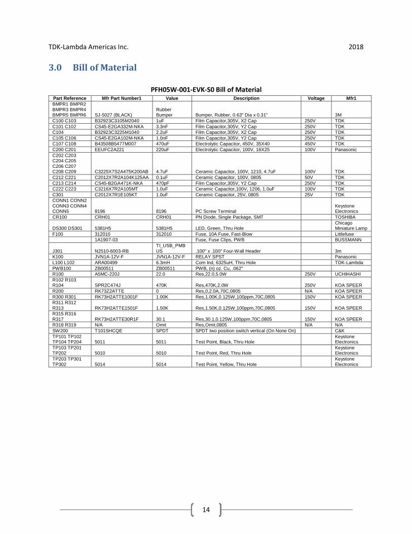
3.0 Bill of Material
PFH05W-001-EVK-S0 Bill of MaterialPart Reference Mfr Part Number1 Value Description Voltage Mfr1BMPR1 BMPR2BMPR3 BMPR4BMPR5 BMPR6 SJ-5027 (BLACK)
RubberBumper Bumper, Rubber, 0.63" Dia x 0.31" 3M
C100 C103 B32923C3105M2040 1uF Film Capacitor,305V, X2 Cap 250V TDKC101 C102 CS45-E2GA332M-NKA 3.3nF Film Capacitor,305V, Y2 Cap 250V TDKC104 B32923C3225M1040 2.2uF Film Capacitor,305V, X2 Cap 250V TDKC105 C106 CS45-E2GA102M-NKA 1.0nF Film Capacitor,305V, Y2 Cap 250V TDKC107 C108 B43508B5477M007 470uF Electrolytic Capacitor, 450V, 35X40 450V TDKC200 C201 EEUFC2A221 220uF Electrolytic Capacitor, 100V, 16X25 100V PanasonicC202 C203C204 C205C206 C207C208 C209 C3225X7S2A475K200AB 4.7uF Ceramic Capacitor, 100V, 1210, 4.7uF 100V TDKC212 C221 C2012X7R2A104K125AA 0.1uF Ceramic Capacitor, 100V, 0805 50V TDKC213 C214 CS45-B2GA471K-NKA 470pF Film Capacitor,305V, Y2 Cap 250V TDKC222 C223 C3216X7R2A105MT 1.0uF Ceramic Capacitor,100V, 1206, 1.0uF 100V TDKC301 C2012X7R1E105KT 1.0uF Ceramic Capacitor, 25V, 0805 25V TDKCONN1 CONN2CONN3 CONN4CONN5 8196 8196 PC Screw Terminal
KeystoneElectronics
CR100 CRH01 CRH01 PN Diode, Single Package, SMT TOSHIBA
DS300 DS301 5381H5 5381H5 LED, Green, Thru HoleChicagoMiniature Lamp
F100 312010 312010 Fuse, 10A Fuse, Fast-Blow Littlefuse1A1907-03 Fuse, Fuse Clips, PWB BUSSMANN
J301 N2510-6003-RBTI_USB_PMBUS .100" x .100" Four-Wall Header 3m
K100 JVN1A-12V-F JVN1A-12V-F RELAY SPST PanasonicL100 L102 ARA00499 6.3mH Com Ind, 6325uH, Thru Hole TDK-LambdaPWB100 ZB00511 ZB00511 PWB, (n) oz. Cu, .062"R100 A5MC-220J 22.0 Res,22.0,5.0W 250V UCHIHASHIR102 R103R104 SPR2C474J 470K Res,470K,2.0W 250V KOA SPEERR200 RK73Z2ATTE 0 Res,0,2.0A,70C,0805 N/A KOA SPEERR300 R301 RK73H2ATTE1001F 1.00K Res,1.00K,0.125W,100ppm,70C,0805 150V KOA SPEERR311 R312R313 RK73H2ATTE1501F 1.50K Res,1.50K,0.125W,100ppm,70C,0805 150V KOA SPEERR315 R316R317 RK73H2ATTE30R1F 30.1 Res,30.1,0.125W,100ppm,70C,0805 150V KOA SPEERR318 R319 N/A Omit Res,Omit,0805 N/A N/ASW200 T101SHCQE SPDT SPDT two position switch vertical (On None On) C&KTP101 TP102TP104 TP204 5011 5011 Test Point, Black, Thru Hole
KeystoneElectronics
TP103 TP201TP202 5010 5010 Test Point, Red, Thru Hole
KeystoneElectronics
TP203 TP301TP302 5014 5014 Test Point, Yellow, Thru Hole
KeystoneElectronics

TDK-Lambda Americas Inc. 2018
15
4.0 Board Files
FIGURE 1 Top side Component Placement

TDK-Lambda Americas Inc. 2018
16
FIGURE 2 Top Layer (Etch 1)

TDK-Lambda Americas Inc. 2018
17
FIGURE 3 Internal Layer (Etch 2)

TDK-Lambda Americas Inc. 2018
18
FIGURE 4 Internal Layer (Etch 3)

TDK-Lambda Americas Inc. 2018
19
FIGURE 5 Bottom Layer (Etch 4)

TDK-Lambda Americas Inc. 2018
20
FIGURE 6 Bottom side Component Placement

TDK-Lambda Americas Inc. 2018
21
FIGURE 7 Circuit Outline

TDK-Lambda Americas Inc. 2018
22
5.0 EMI Conducted Test Results
Conducted Emissions CISPR22 Class B Test Results
EUT Model: PFH500F-28-100-R Test Dates: 04/12/2018
Test Location: National Technical Systems Engineer: Michael D. Lawrence - TDK
1701 E. Plano Parkway #150 Ervin Williams - NTS
Plano, TX 75074
Test Equipment
Asset #: Device: Manufacture: Model: Cal Date: Cal Due Date:NTS –WC021859
SpectrumAnalyzer PSA
Series
Agilent E4440A 6/29/17 6/29/18
NTS –WC021314
LISN ROHDE &SCHWARZ
ESH3-Z5 5/8/17 5/8/18
NTS –WC021350
Transient Limiter HAMEGInstruments
HZ560 7/4/17 7/4/18
Figure 1
NTS (Richardson, TX) Conducted Emissions CISPR22 Class B Setup
TDK-Lambda Americas Inc. 2018
23
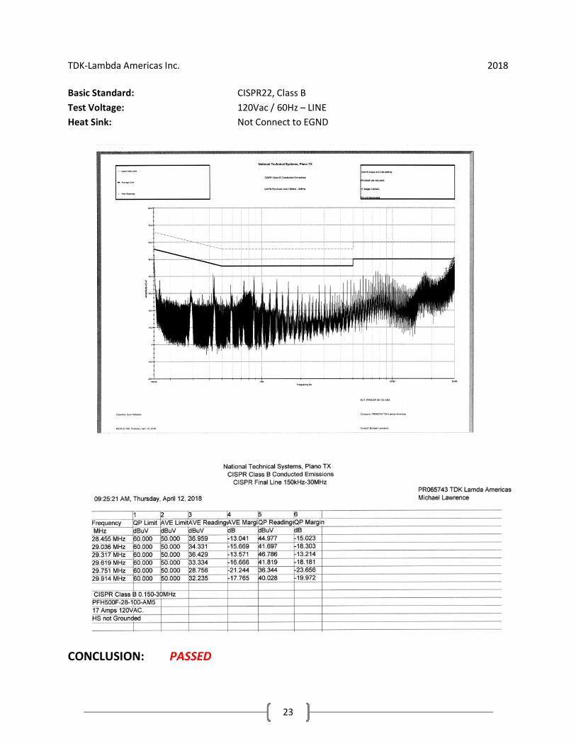
Basic Standard: CISPR22, Class B
Test Voltage: 120Vac / 60Hz – LINE
Heat Sink: Not Connect to EGND
CONCLUSION: PASSED

TDK-Lambda Americas Inc. 2018
24
Basic Standard: CISPR22, Class B
Test Voltage: 120Vac / 60Hz - NEUTRAL
Heat Sink: Not Connect to EGND
CONCLUSION: PASSED

TDK-Lambda Americas Inc. 2018
25
Basic Standard: CISPR22, Class B
Test Voltage: 120Vac / 60Hz – LINE
Heat Sink: Connected to EGND
CONCLUSION: PASSED

TDK-Lambda Americas Inc. 2018
26
Basic Standard: CISPR22, Class B
Test Voltage: 120Vac / 60Hz - NEUTRAL
Heat Sink: Connected to EGND
CONCLUSION: PASSED

TDK-Lambda Americas Inc. 2018
27
Basic Standard: CISPR22, Class B
Test Voltage: 230Vac / 50Hz – LINE
Heat Sink: Not Connect to EGND
CONCLUSION: PASSED

TDK-Lambda Americas Inc. 2018
28
Basic Standard: CISPR22, Class B
Test Voltage: 230Vac / 50Hz - NEUTRAL
Heat Sink: Not Connect to EGND
CONCLUSION: PASSED

TDK-Lambda Americas Inc. 2018
29
Basic Standard: CISPR22, Class B
Test Voltage: 230Vac / 50Hz – LINE
Heat Sink: Connected to EGND
CONCLUSION: PASSED

TDK-Lambda Americas Inc. 2018
30
Basic Standard: CISPR22, Class B
Test Voltage: 230Vac / 50Hz - NEUTRAL
Heat Sink: Connected to EGND
CONCLUSION: PASSED