permanent, high performance, drop-in replacement catalyst...
TRANSCRIPT
TM
Driving Reaction Technology
Stackable Structural Reactor (SSR®) Technology White Paper No. 102
Permanent, High Performance, Drop-In Replacement Catalyst for Steam Reforming Hydrogen Plants
William A Whittenberger, BSME, MBA, PECatacel Corporation
Keywords: higher hydrogen yield, reduced energy consumption, permanent catalyst replacement,
signifi cant increase in capacity, extended plant lifecycle, cost savings
Introduction
Driving reaction technology! That is the overall goal today – creating high performance, low cost reaction solutions that combine catalytic and heat transfer functions that lead to breakthroughs in production and energy effi ciency. Specifi cally, one of these solutions is geared toward advanced and signifi cantly improved hydrogen production through the steam reforming process.
Traditionally, the multiple alloy steel tubes that are suspended vertically in a heated chamber (typically 1000°C to 1100°C) are fi lled with loose ceramic media impregnated with catalytic metals. Although this process has been in use for many decades, this method has expensive drawbacks:
• After several startup and shutdown cycles, the ceramic media crushes to powder due to the different thermal expansion rates between the metal tube and ceramic media.
• Accumulation of this ceramic powder in the tubes leads to plugging of the reactor to the point where the media must be removed and replaced every three to fi ve years.
1
• This recurring event has a signifi cant negative impact on plant lifecycle costs. Plus, it creates additional costs for replacement material, labor, hazardous waste disposal and plant downtime.
To solve this problem, Catacel Corporation has developed, tested and perfected a permanent catalyst-coated metal foil replacement with specially designed corrugation and fl ow channels that can be easily connected and dropped into the reformer tubes.
This White Paper takes an in-depth look at Catacel’s current industry-leading reaction technology expertise and special competency strengths. In addition, substantial detail is provided on the following:
• Catalysts for steam reforming of natural gas• Catacel capabilities• Design and testing of Catacel’s permanent, high
performance, drop-in replacement catalyst solution for steam reforming hydrogen plants
• Design and testing of Catacel’s permanent, high performance, drop-in replacement catalyst solution for steam reforming hydrogen plants

Stackable Structural Reactor (SSR®) Technology
Contents Page
Background: Hydrogen Generation Through
Steam Reforming of Hydrocarbons ................................................................................ 4
How it Works .............................................................................................................................4
Increasing Demand for Hydrogen ...............................................................................................4
• Growth of the Hydrogen Industry .......................................................................................4
• Industries that use hydrogen ..............................................................................................4
• Steam Methane Reforming in Brief .....................................................................................4
• Traditional Ceramic Catalyst Media .....................................................................................5
Catacel’s New Industry-Leading Reaction Technology.............................................. 5
Heat Management .....................................................................................................................5
High Temperature Foil Substrates ..............................................................................................8
Metal Foil Structures ......................................................................................................... 8
Foil Forming ...............................................................................................................................8
Foil Surface Coating and Durable Bonding of Catalytic Material .................................................9
Catalysts for Steam Reforming of Natural Gas ........................................................... 9
Catacel Nickel Catalysts ............................................................................................................9
Catacel’s Permanent, High Performance, Drop-In,
Replacement Catalyst Solution for Hydrogen Plants ................................................ 10
System Design .........................................................................................................................10
Performance Testing .................................................................................................................10
User Benefi ts ............................................................................................................................11
An Alternative Heat Transfer Benefi t – Additional Capacity ........................................................12
Lower Cost New Plant Design Benefi t.......................................................................................12
Extended Catalyst Life from the Surface Area ...........................................................................12
2

Stackable Structural Reactor (SSR®) Technology
Contents Page
Easy SSR® Installation/Removal ..................................................................................... 12
Steel Mill Application Case Study .................................................................................. 12
Value-In-Use Example ....................................................................................................... 13
Alternative Process Applications ................................................................................... 13
About Catacel Corporation .............................................................................................. 14
Catacel Capabilities .......................................................................................................... 15
Design ......................................................................................................................................15
Synthesis and Evaluation ..........................................................................................................15
Bonding ....................................................................................................................................15
3

4
Background: Hydrogen Generation Through Steam Reforming of Hydrocarbons
How It Works
Hydrogen production from natural gas and other hydrocarbon fuels is an extremely important activity throughout the world.
Typically, hydrogen is produced from hydrocarbon fuels via chemical reforming using combinations of steam reforming and partial oxidation. Steam reforming of the simple hydrocarbon methane occurs with the following reaction:
CH4 + H2O CO + 3H2
This reaction is normally performed in the presence of a catalyst and is highly endothermic.
In practice, excess steam in the input stream, side reactions and reaction equilibrium dictate that other reaction products are formed, including CO2 as well as un-reacted CH4 and H2O. Normally, the output stream – called syngas (from synthetic gas) – is 50% to 70% H2.
In conventional reforming processes, reaction temperatures in the 800°C to 900°C range are required to react most of the hydrocarbon fuel.
The catalyst typically employed contains an active nickel (Ni) metal component supported on loose ceramic oxide media.
Increasing Demand for Hydrogen
Growth Of The Hydrogen Industry
According to 2005 statistics, some 50 million metric tons of hydrogen – equivalent to 170 million tons of oil – is produced globally. The industry growth rate has averaged 10% annually.
Industries that use Hydrogen
Many industrial manufacturing processes require hydrogen, particularly in the petrochemical, steel, food, silicon chip, glass, ammonia and methanol industries.
Steam Methane Reforming in Brief
The process utilizes multiple alloy steel tubes suspended vertically in a heated chamber typically operating at 1000° to 1100°C (Figure 1). Normally, these tubes are 3” to 6” in diameter and up to 40-feet tall. The tubes are fi lled with loose ceramic media impregnated with catalytic metals. Steam and the selected hydrocarbon fuel are fed to the top of the tubes. Syngas, containing 50% to 70% hydrogen, is extracted from the bottom. This process can also be reversed and fed from the bottom with the exit at the top.
Figure 1 – The steam methane reforming process in a typical hydrogen plant

5
Traditional Ceramic Catalyst Media
As noted, the traditional ceramic media is impregnated with catalytic metals. To maximize the available surface area and promote heat transfer, this media can be shaped as pellets, balls, small saddles, “wagon wheels” and similar confi gurations (Figure 2).
Figure 2 – Catalyst-impregnated ceramic pellet
While this conventional production method has been in use for nearly a century, there are signifi cant drawbacks. Specifi cally:
It tends to crush to powder after startup and shutdown cycles.
This is the direct result of different thermal expansion rates between the metal tube and ceramic media. When the tube heats, it expands, but the ceramic media does not. Instead, the media settles a bit. When the reactor is shut down, the tube cools and contracts, crushing some of the ceramic media to powder.
Accumulation of this powder in the tube leads to plugging of the reactor. This “clogging” requires that the media be removed and replaced every three to fi ve years.
This recurring event has a signifi cant negative impact on plant lifecycle cost. In addition to creating a material replacement cost, there are associated additional costs for labor, downtime and hazardous waste disposal because nickel catalyst is a listed hazardous material.
Steam reforming is an endothermic reaction, requiring a constant supply of heat.
This heat is provided to the catalyst media from the furnace through the wall of the container tube. The catalyst media near the tube wall picks up heat readily. However, heat transfer to the media near the center of the tube is more diffi cult, meaning the catalyst at the center is less effective (Figure 3). As a result, reaction effi ciency is compromised due to less than ideal heat transfer through the catalyst particles.
Catacel’s New Industry-Leading Reaction Technology
Heat Management
Most catalytic reactions include heat fl ux. Exothermic reactions release heat, while endothermic reactions require a heat input. One classical design approach is to perform the catalytic reaction in an adiabatic reactor, then deal with the heat issues elsewhere, such as with a heat exchanger or with dilution. Another classic approach uses ceramic packed bed catalysts, which support the reaction and enable a modest heat fl ux.
To improve overall system performance, the Catacel approach combines high performance reaction with high performance heat transfer. This approach allows operation in less space, with less weight, and for less money over time. In many reactions that are heat transfer limited, it is often possible to achieve higher throughput rates.

6
Figure 3 – Heat transfer inside a reformer tube with ceramic catalyst media

7
In combining these two functions, Catacel puts the catalyst on formed foil surfaces, which also serve as the heat exchanger. To move heat in different directions and quantities, the foil surfaces can be arranged in a wide variety of confi gurations and structures.
The tradeoffs and constraints between surface area, pressure drop and heat transfer normally drive the design of a reactor. Each of these three important properties is directly related to the materials used for the reactor. Ceramic pellet catalyst supports designed for good surface area and reasonable pressure drop will offer modest heat transfer. Ceramic pellet supports with higher heat transfer, or higher surface area, usually pay a strong pressure drop penalty. Hence, the operating window of the reactor is limited by the
fundamental properties of the support. Catacel’s metal foil catalyst supports can be confi gured for high performance heat transfer, with high surface area, at modest pressure drop.
Catacel has successfully developed and installed Stackable Structural Reactors (SSR®) as a replacement for the ceramic media used in conventional steam reformer tubes. This reactor (Figure 4) is a honeycomb made from a special grade of high temperature stainless steel foil coated with a reforming catalyst. These individual reactors, which are about the size and shape of a coffee can, are stacked one upon another inside the vertical steam reforming tubes (Figure 5).
Figure 5 – SSR® stack inside a reformer tubeFigure 4 – Catacel’s Stackable Structural Reactor (SSR®)

8
Figure 6 - Catacel can specially engineer a variety of metal foil honeycombs and structures that operate in hostile conditions while providing high performance heat transfer and heat management
Table 1 provides a heat transfer comparison between ceramic, modifi ed ceramic and metal foil catalyst media. This comparison shows the effect of attempting to modify a ceramic support to operate in a higher heat transfer window. More surface area is available, but pressure drop becomes intolerably high. Metal foil changes the operating window, delivering the required heat transfer and much higher surface area at only a modest increase in pressure drop.
The fundamental properties of the foil support allow the process to be operated in a previously unavailable window. This new operating window is typically quite favorable in terms of size, weight and throughput.
High Temperature Foil Substrates
Most catalytic combustion and many reforming reactions operate in the 700°C to 900°C range. Thus, the foil substrate for the applied catalyst needs to be strong and stable at those temperatures. This normally limits the choice to one of the rather expensive “super alloys” in the $100 per-lb. range.
To control costs, Catacel uses a special alloy for its foil structures – Fecralloy® – which can be purchased for signifi cantly less. Fecralloy® is a blend of iron, chrome, aluminum and rare earth. When heated, Fecralloy® makes aluminum oxide, which is ideal for the application of catalyst to the foil surface. This oxide also provides protection that makes the alloy chemically stable in most high temperature environments. Fecralloy® is considered by many to be a diffi cult material to work with because its ductility is considerably low. It tends to break easily when formed, and its strength at high temperatures is modest at best.
Catacel has been working with Fecralloy® for many years and has developed a strong expertise in using
Table 1 – Property Comparison Modifi ed Ceramic Ceramic Metal Foil
Heat Transfer 1.0 1.3 1.3Surface Area 1.0 ~ 1.5 ~ 2.5Pressure Drop 1.0 ~ 5.0 ~ 1.5
this inexpensive alloy in place of the super alloys. Catacel can form this material into a myriad of useful support shapes in spite of its brittle properties. For the SSR®, Catacel is able to deliver this alloy in a special confi guration that is mechanically stable at the high steam reforming temperatures.
With its ability to enable higher capacity, reduce energy consumption and provide for longer life, Catacel’s SSR® is a superior direct replacement for the loose ceramic catalyst media traditionally used in industrial plants throughout the world. The SSR® will not crush and provides a signifi cantly longer life, possibly enduring as long as the plant itself.
Metal Foil Structures
Foil Forming
Catacel can custom engineer and manufacture catalytic heat-exchanging materials in a wide range of geometries, forms and shapes (Figure 6). Coated foils can be supplied in virtually any shape including:
• Cylinders and annular constructs• Rectangles and cubic or planar forms• Rhombic, trapezoidal or tapered forms • Pie and disc shapes • Combinations of the above

9
Corrugations and fi ns are possible from simple fl at foils to complex forms including:
• Straight, herringbone and skew corrugations from 20 to 2000 cpsi
• Triangular or rectangular formed fi ns, with straight or complex profi les in the fl ow direction
Catacel’s SSR® for hydrogen production (Figure 7) features custom designed high surface area metal fi ns coated with a high activity reforming catalyst. The fi ns are arranged for superior heat transfer that enables the use of lower furnace temperatures with consequent overall system energy savings and extended tube and furnace life. In addition, they are crush-proof for exceptional long life.
In determining the proper foil shape and heat exchanging structure for SSR® drop-in replacements, the success key was to correctly evaluate the temperature and heat transfer properties of the design. The main issue with using Fecralloy® foil is to make sure that the structure will function as intended and remain mechanically stable in supporting the 800°C to 900°C reaction. In some hydrogen production systems that operate under pressure, for example, the tubes “creep” and get larger in diameter over time. In this type of application, it is critical to make sure that the foil structure follows the growth of the tube.
Figure 7 – Close-up of SSR® metal foil surface
Catacel has more than 30 years of structure design engineering and manufacturing experience with Fecralloy® metal foil.
Foil Surface Coating and Durable Bonding of Catalytic Material
Much has been written on the application of catalytic coatings to Fecralloy® foil. In Catacel’s experience with the material, it has been learned that there are a number of critical issues that must be overcome if the catalyst material is to correctly bond and stay in place in a high temperature steam-reforming environment.
In the design and manufacture of the SSR® drop-in replacement catalyst for steam reforming hydrogen plants, the following questions had to be answered:
• What mechanical and/or heat-treating preparations are necessary to provide an ideal foil surface for the coating process and its end use?
• What coating and adherence properties and procedures would be best for steam reforming applications?
• What is the best way to bring the catalyst coating and prepared foil surface together to ensure catalytic performance and durability?
Catacel believes its experience in foil surface coating and durable bonding of catalytic materials is second to none.
Catalysts for Steam Reforming of Natural Gas
Catacel Nickel Catalysts
Beyond the “textbook” catalysts that are used for reforming reactions, Catacel has developed a number of formulations that work extremely well in specifi c application situations. The catalyst Catacel uses for steam reforming of natural gas is one example of a specifi cally developed metal package. This nickel-based catalyst maintains stability in the required 800°C to 900°C temperature range.
10
Catacel’s Permanent, High Performance, Drop-in, Replacement Catalyst Solution for Hydrogen Plants
System Design
Ceramic catalytic media is randomly placed in the steel tubes. In operation, the fl ow gathers heat from the tube walls and moves indiscriminately inside the tube around the media. By design, the performance of ceramic media is based on its arbitrary placement. The drawback: there are performance limits with randomly placed ceramic catalytic media.
Catacel’s Stackable Structural Reactor features precision-engineered fl ow channels in the fi n shaped metal foil to signifi cantly increase the amount of catalytic surface area and control the cyclic fl ow. The fi ns are coated with high activity reforming catalyst.
The result: an improved way to pick up heat from the tube sidewalls, excellent catalyst utilization, longer catalyst life – and most important – superior heat transfer. Additionally, the crush-proof metal foil substrate is a better conductor of heat than ceramic pellets.
Performance Testing
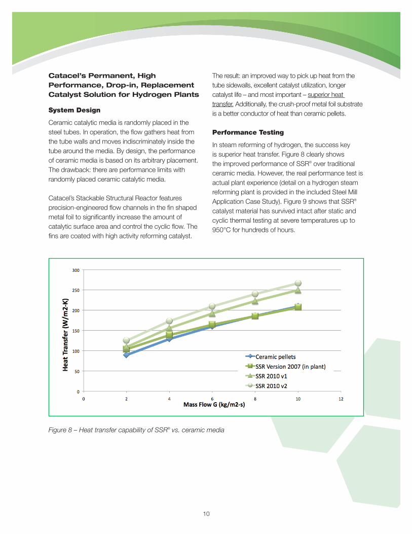
In steam reforming of hydrogen, the success key is superior heat transfer. Figure 8 clearly shows the improved performance of SSR® over traditional ceramic media. However, the real performance test is actual plant experience (detail on a hydrogen steam reforming plant is provided in the included Steel Mill Application Case Study). Figure 9 shows that SSR® catalyst material has survived intact after static and cyclic thermal testing at severe temperatures up to 950°C for hundreds of hours.
Figure 8 – Heat transfer capability of SSR® vs. ceramic media

Figure 9 – SSR® after severe static (9a) and cyclic (9b) testing
Figure 9a Figure 9b
User Benefi ts
There are two ways retrofi t users gain an advantage with the signifi cantly higher heat transfer and greater surface area properties of Catacel’s Stackable Structural Reactor media:
1. A capacity increase2. Energy savings and extended tube and furnace life
due to lower tube and furnace temperatures 3. Extended catalyst life resulting from catalyst
materials spread over more surface area
In a reformer, the reaction temperature is always the same regardless of the catalyst media because it is governed mostly by equilibrium. In order to drive heat to the media, the tubes must be hotter than the reaction temperature. And the furnace must be hotter still to drive heat to the tubes. Summed up, there has to be temperature differentials to drive the process.
The catalyst media can have a large effect on the furnace and tube temperatures that are needed to achieve the required reaction temperature. Ceramic
media, with modest heat transfer capability, typically operates with a 90°C to 100°C temperature differential between media and tube. SSR® media, with signifi cantly better heat transfer capability, decreases that differential by 35°C or more. This means that the tubes operate cooler, extending the tube life.
Then, and most important, the user can also decrease furnace temperature by 40° to 50°C. Energy supplied to the furnace can be decreased by approximately 10% and as a result, the furnace would be expected to last longer. But, the savings become even greater. Hydrogen steam reforming plants use the process off-gas stream to supply about half of the fuel for the furnace. This fuel component is still available when SSR® media is used. So “new fuel” is needed for only about half of the total furnace heat load. Consequently, when the total furnace heat load is reduced by 10%, the need for new fuel (the fuel you pay for) is reduced by 20%. In addition, the associated carbon emissions from the fuel are reduced by the same percentages.
11

An alternative heat transfer benefi t is additional capacity. Instead of lowering tube and furnace temperatures, users have the option of pushing 25% to 35% more product through the reformer. Additional process heat is needed, but the higher heat transfer capability of SSR® media allows furnace and tube temperatures to remain similar to those with ceramic media operating at the original throughput. However, this may also require appropriate changes to the plant.
Lower new plant design cost benefi t. By designing a new plant to run at the same temperatures to increase product throughput, the superior heat transfer properties of Catacel’s SSR® technology makes it possible to build a smaller reformer at a substantial cost savings.
Extended catalyst life from the surface area. The surface area available with SSR® media is typically about 2.5 times that available with ceramic media. This higher surface area means that more active catalyst ingredients are available to the reaction. This has little effect when catalysts are new and very active. But, as the catalyst materials degrade over time, their availability has a profound effect. Depending on how the plant is operated, ceramic media can degrade to an unacceptable level in fi ve to eight years. The additional surface area of SSR® media will allow it to last at least twice as long as ceramic media before deterioration is a factor.
Easy SSR® Installation/Removal
Traditional ceramic media is poured into the tubes with the use of special tools to prevent breakage. Removal, due to degradation of the media over time to powder, is by a vacuum system.
Catacel’s SSR® media is delivered from the factory as canisters about the size of a coffee can. Canisters are connected into groups of three- to
four-feet long before installing in the reformer. The groups are installed by sliding them down from the tube top. Due to the tight fi t, there is a little drag. To make sure that the tube is fi lled tightly, a weight on a rope is used to lower each group. A 40-ft. long tube might contain ten SSR® groups. When heated, the individual canisters expand a small amount within the tube.
Removal, after a very long life, is with a special tool that hooks to the top of each group to pull it out of the tube. Should an individual canister break during removal, it will break at a pre-designed point. The remaining piece is easily grasped by another special tool.
Steel Mill Application Case Study
A 250 cubic meter-per-hour conventional small hydrogen plant for steel making in Turkey has been in operation since July 2008. It is a can-type reformer with up fl ow, four 22-ft. long tubes holding 8 cu. ft. of Catacel’s SSR® catalyst media (note: SSR® performance has even been considerably improved in the nearly two years since this installation). A companion plant at the same location has been running on ceramic pellets since the early ‘90s.
The new plant came on-line immediately and was running at equilibrium conditions after several days of fi ne-tuning. At the nine-month point, the plant continued to operate as it was when new. In October 2009, the plant experienced a process upset that dramatically reduced its hydrogen generating ability. While the exact cause of the upset was never determined, steaming the SSR® media for several days returned the performance to acceptable levels. Today, the plant is fully operational with the same conditions as when it was opened. It was noted by plant personnel that had the tubes been fi lled with ceramic media, they would not likely have survived the upset event.
12

Value-In-Use Example
A fi nite-difference model of a reformer system was created to estimate the short- and long-term performance effects of SSR® vs. ceramic media. The model was validated against lab data and actual plant performance data observed at the plant described above. The discussion below describes some scenarios that show how that plant would operate differently if confi gured with ceramic media.
As illustrated in Figure 10, if the reformer were operating with new ceramic media, the reaction temperature would be approximately 824°C. The model therefore suggests that tube temperature will be about 918°C, and furnace temperature about 1036°C. Over time, the catalyst degrades. Because of this degradation, after six years, the reaction temperature must increase by 21°C to 845°C in order to achieve the same effect. Tube and furnace temperatures will increase to their practical limits of 948°C and 1071°C respectively. Catalyst must be changed to get the temperatures back in range, if it had not already been changed because of breakage and plugging.
In the same reformer operating with Catacel’s new SSR® technology, the reaction temperature (when new) will be the same 824°C. However, the improved heat transfer allows the tubes and furnace to operate at approximately 877°C and 983°C respectively. After six years, the catalyst material in SSR® has degraded only a small amount because of its higher surface area. Reaction temperature is now 827°C. Tube and furnace temperatures are 888°C and 1004°C respectively, which is nowhere near their limit. There is signifi cant life remaining in the SSR catalyst!
The model is capable of estimating fuel usage for the reformer. Table 2 – “Fuel Usage Comparison Between Ceramic & SSR® Media” – shows how the temperatures and furnace fuel cost change over time. It shows a clear fuel cost advantage for SSR® in years one through six. It also shows that SSR® media can last through year 12, avoiding entirely an expensive and time-consuming catalyst change-out at the end of year six.
Alternative Process Applications
There are many chemical and refi ning processes that also use reformer “pellets and pipes” reactors. While these reactors are different than those used for steam reforming hydrogen, the concept is the same. Importantly, these processes for making such products as ammonia, methanol, formaldehyde, ethylene oxide, etc., are also limited by heat transfer and smaller catalytic surface areas. With different catalyst ingredients, Catacel Stackable Structural Reactor media has great promise and opportunity in helping plant operators of these alternative processes improve the performance of their operations.
13
Deg
rees
°C
1050
1000
950
900
850
800Ceramic
Reaction Tube Wall Furnace
SSR
SSR® vs. Ceramic Pellets
Lower Furnace Temperature by ~30°C !
Figure 10 – The improved heat transfer of SSR® allows lower tube and furnace temperatures

About Catacel Corporation
Catacel makes engineered materials that combine catalytic and heat exchange functions to deliver breakthrough performance in size, weight, throughput and energy effi ciency to a wide range of energy and industrial reaction processes.
These materials are made by coating thin-formed metal foils with catalysts or sorbents. The company is a manufacturer that provides solutions for challenging applications using its diverse background in durable metal reactors, heat management, reaction design, catalytic chemistry and large-scale integrated production techniques. Currently, the company is developing and commercializing products for the fuel cell, hydrogen, gas-to-liquid process and aerospace industries. The technical and scientifi c foundation for these products lies in the strong crossover application of the technology its principals have pioneered in the catalytic conversion industry.
Catacel’s technology strengths are designing, creating and effi ciently coating shaped metal foils and heat exchange solutions relating to fuel reforming, catalytic chemistry and combustion. The company’s core competencies include:
• Catalytic materials synthesis and evaluation• Application of materials to metal foil
(particularly catalysts)• Heat and mass transfer to honeycomb surfaces• Metal foil design for long-term durability• High temperature alloys, uses and properties• High temperature and high pressure evaluation of
catalysts and monoliths• Continuous coating and continuous foil
processing• Catalytic combustion and catalytic system design• Design and implementation of manufacturing
processes for catalytic and heat exchange products
• Metal forming, welding and joining
14
Table 2 – Fuel Usage Comparison Between Ceramic & SSR® Media
250m3/hr H2 plant
New
After Yr1
After Yr2
After Yr3
After Yr4
After Yr5
After Yr6
After Yr7
After Yr8
After Yr9
After Yr10
After Yr11
After Yr12
Nat. gas at $7/mm BTU
CERAMIC MEDIA
Reaction temp.(°C) 824 824 824 827 831 837 845
Tube temp.(°C) 918 921 923 927 933 939 948 (replace)
Furnace temp.(°C) 1036 1039 1042 1047 1054 1062 1071
Furnace fuel, $/year $79,887 $80,436 $81,234 $82,678 $84,539 $87,122 $90,309
SSR® MEDIA
Reaction temp.(°C) 824 824 824 824 824 824 827 832 838 846 856 869 884
Tube temp.(°C) 877 877 878 879 882 885 888 895 903 911 920 934 951
Furnace temp.(°C) 983 985 988 991 994 998 1004 1010 1018 1027 1038 1050 1064
Furnace fuel, $/year $68,037 $68,590 $69,110 $69,764 $70,466 $71,213 $72,641 $74,596 $76,955 $79,786 $83,410 $87,939 $93,202
Savings $11,850 $11,846 $12,124 $12,914 $14,073 $15,909 $17,668
Total Savings $11,850 $23,696 $35,820 $48,734 $62,807 $78,716 $96,384
Catacel Corporation7998 Gotham RoadGarrettsville, Ohio [email protected].
TM
Driving Reaction Technology
03/2010©2010 Catacel Corporation.
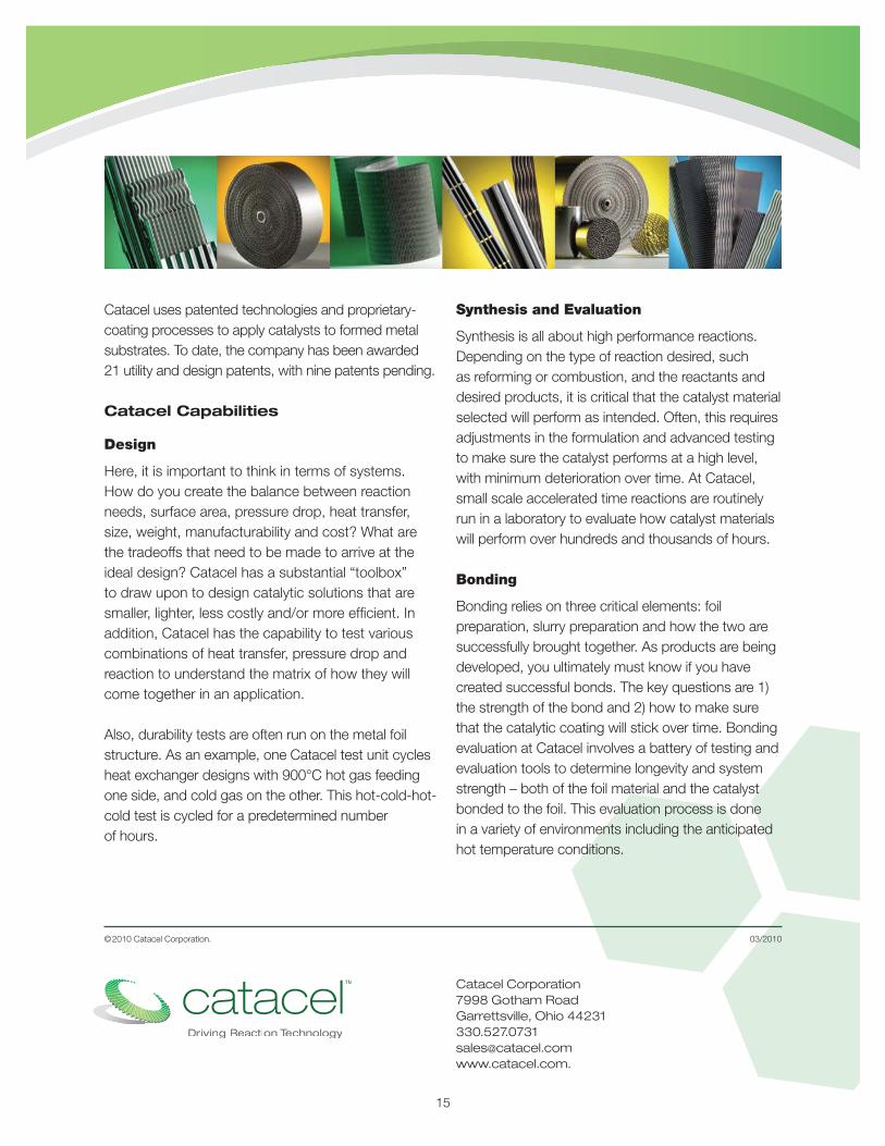
Catacel uses patented technologies and proprietary-coating processes to apply catalysts to formed metal substrates. To date, the company has been awarded 21 utility and design patents, with nine patents pending.
Catacel Capabilities
Design
Here, it is important to think in terms of systems. How do you create the balance between reaction needs, surface area, pressure drop, heat transfer, size, weight, manufacturability and cost? What are the tradeoffs that need to be made to arrive at the ideal design? Catacel has a substantial “toolbox” to draw upon to design catalytic solutions that are smaller, lighter, less costly and/or more effi cient. In addition, Catacel has the capability to test various combinations of heat transfer, pressure drop and reaction to understand the matrix of how they will come together in an application.
Also, durability tests are often run on the metal foil structure. As an example, one Catacel test unit cycles heat exchanger designs with 900°C hot gas feeding one side, and cold gas on the other. This hot-cold-hot-cold test is cycled for a predetermined number of hours.
Synthesis and Evaluation
Synthesis is all about high performance reactions. Depending on the type of reaction desired, such as reforming or combustion, and the reactants and desired products, it is critical that the catalyst material selected will perform as intended. Often, this requires adjustments in the formulation and advanced testing to make sure the catalyst performs at a high level, with minimum deterioration over time. At Catacel, small scale accelerated time reactions are routinely run in a laboratory to evaluate how catalyst materials will perform over hundreds and thousands of hours.
Bonding
Bonding relies on three critical elements: foil preparation, slurry preparation and how the two are successfully brought together. As products are being developed, you ultimately must know if you have created successful bonds. The key questions are 1) the strength of the bond and 2) how to make sure that the catalytic coating will stick over time. Bonding evaluation at Catacel involves a battery of testing and evaluation tools to determine longevity and system strength – both of the foil material and the catalyst bonded to the foil. This evaluation process is done in a variety of environments including the anticipated hot temperature conditions.
15