period #12: bending behavioruser.engineering.uiowa.edu/~swan/courses/57019/period_12_2014.pdfa shear...
TRANSCRIPT

ENGR:2750 Mech. Def. Bodies 12.1The University of Iowa
Period #12: Bending Behavior
A. Next Topic
Chapter 4 dealt with axial loading of axial members (rods)
Chapter 5 dealt with torsional loading of axial members (shafts)
Chapters 6 and 7 deals with transverse loading of axial members (beams).
Our goal in studying beams is to quantify the internal strains and stresses in members subjected to transverse loads.
The University of IowaENGR:2750 Mech. Def. Bodies 12.2
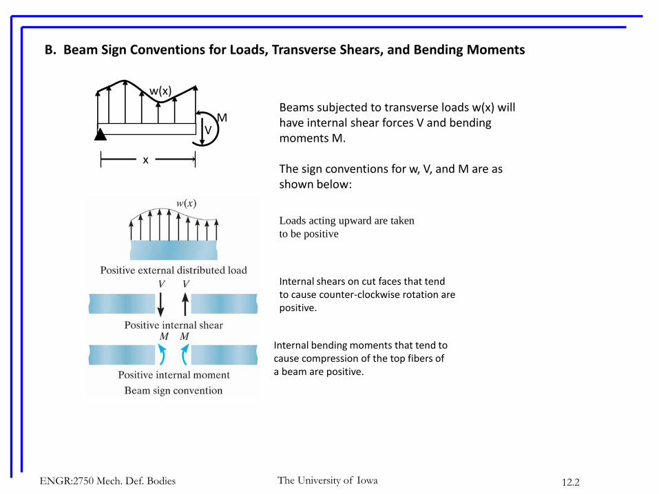
B. Beam Sign Conventions for Loads, Transverse Shears, and Bending Moments
Loads acting upward are taken
to be positive
Internal shears on cut faces that tend to cause counter-clockwise rotation are positive.
Internal bending moments that tend to cause compression of the top fibers of a beam are positive.
VM
x
Beams subjected to transverse loads w(x) will have internal shear forces V and bending moments M.
The sign conventions for w, V, and M are as shown below:
w(x)

ENGR:2750 Mech. Def. Bodies 12.3The University of Iowa
C. Calculation of the Shear (V) and Moment (M) distributions
A shear diagram is a graphical representation of the transverse shear force V distribution in a beam.
A moment diagram is a graphical representation of the bending moment M distribution in a beam.
Given a loading that acts on specific beam with well-defined support conditions, it is necessary to be able to compute both V(x) and M(x).
1. Relation between w and V
Consider an infinitesimal beam segment of length dx:
dxxwVVxwdx
dV
xwdx
xVdxxV
dxxVdxxwxV
F
B
A
AB
y
)(
)()()(
)()()(
higher]or 2order of erms[Neglect t 0

The University of IowaENGR:2750 Mech. Def. Bodies 12.4
In words, the shear in a beam is obtained by integrating the load function.
Alternatively, the slope of the shear diagram represents the intensity of the load function.

The University of IowaENGR:2750 Mech. Def. Bodies 12.5
When a discrete load acts on a beam, the shear diagram increases or decreases with that load.
2
P
2
P
P
V(x)
2
P
2
P

The University of IowaENGR:2750 Mech. Def. Bodies 12.6
2. Relation Between V and M
Consider an infinitesimal segment of a beam dx:
B
A
AB dxxVMMxVdx
dM
xVdx
xMdxxM
dxxVdxxMxM
M
)(
)()()(
0)()()(
higher]or 2order of termsall[Neglect 0

In words, the moment in a beam is obtained by integrating the shear.
Alternatively, the slope of moment diagram at each point represents the shear at each point
The University of IowaENGR:2750 Mech. Def. Bodies 12.7

The University of IowaENGR:2750 Mech. Def. Bodies 12.8
When a concentrated clockwise moment is applied to a beam, the moment distribution increases with that moment.
P
V(x)
P
P
M=PL
M(x)
2
L
2
L
2
PL
2
PL
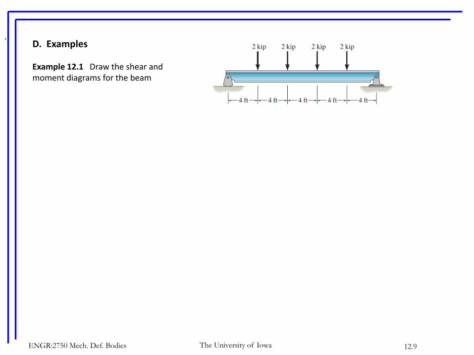
D. Examples
Example 12.1 Draw the shear and moment diagrams for the beam
,
The University of IowaENGR:2750 Mech. Def. Bodies 12.9

The University of IowaENGR:2750 Mech. Def. Bodies 12.10
Example 12.2. Express the internal shear and moment in terms of x and then draw the shear and moment diagrams.
