performance scalability efficiency · 2018. 7. 5. · 3 dimensions of excellence 3 lcs3 3...
TRANSCRIPT

THE GLOBAL SPECIALIST IN ELECTRICAL AND DIGITAL BUILDING INFRASTRUCTURES
DATA CENTERLOCAL AREA NETWORK
3 DIMENSIONS OF EXCELLENCE
PERFORMANCE SCALABILITY EFFICIENCY

2
3 DIMENSIONS OF EXCELLENCE
PERFORMANCE SCALABILITY EFFICIENCY

33 DIMENSIONS OF EXCELLENCEWWW.LEGRAND.CO.NZ
LCS3 3 DIMENSIONS OF EXCELLENCEWWW.LEGRAND.CO.NZ
LCS3
3 DIMENSIONS OF EXCELLENCE
PERFORMANCE SCALABILITY EFFICIENCY
CONTENTSLegrand - A global playerLegrand Group - A leading company for all your IT networksOur digital infrastructure expertiseHigh PerformanceScalability & MaintenanceEfficiencyEasy installationLCS3 Data Center - Enclosure & aisle containmentAisle Containment performance, efficiency & scalabilityMicro data centerLocal Area NetworkPDUs - Solutions for any configurationCord Locking System - Innovation at the heart of PDUsZERO-U PDUs - Innovation & performance1U PDUs - Innovation & ConvenienceProtection accessories Support you can rely onEvolution of standard 11801 Edition 3 – 2017CAT. 8 - Understanding the new performance category for balanced twisted pair cable Fibre optic system - Transmission speed from 40 Gbps to 100 GbpsFibre considerations when migrating to 40/100 Gigabit EthernetCPR – Construction Products Regulation
4
6
8
10
20
30
32
34
38
42
43
44
46
48
50
52
54
56
58
62
66
70

4
Legrand A global player
From control and connection
interfaces to cable management,
energy distribution and data
distribution systems,
Legrand provides a host
of solutions designed to manage
lighting, energy, networks
and building access.
4 KEY AREAS of expertise
Legrand is the global specialist
in electrical and digital building
infrastructures. The Group
offers a comprehensive range
of solutions and services
tailored to residential,
commercial and industrial
applications. The scope of
its offering and its
leading positions make
Legrand a worldwide
benchmark.
3 DIMENSIONS OF EXCELLENCE
PERFORMANCE SCALABILITY EFFICIENCY
53 DIMENSIONS OF EXCELLENCEWWW.LEGRAND.CO.NZ
LCS3
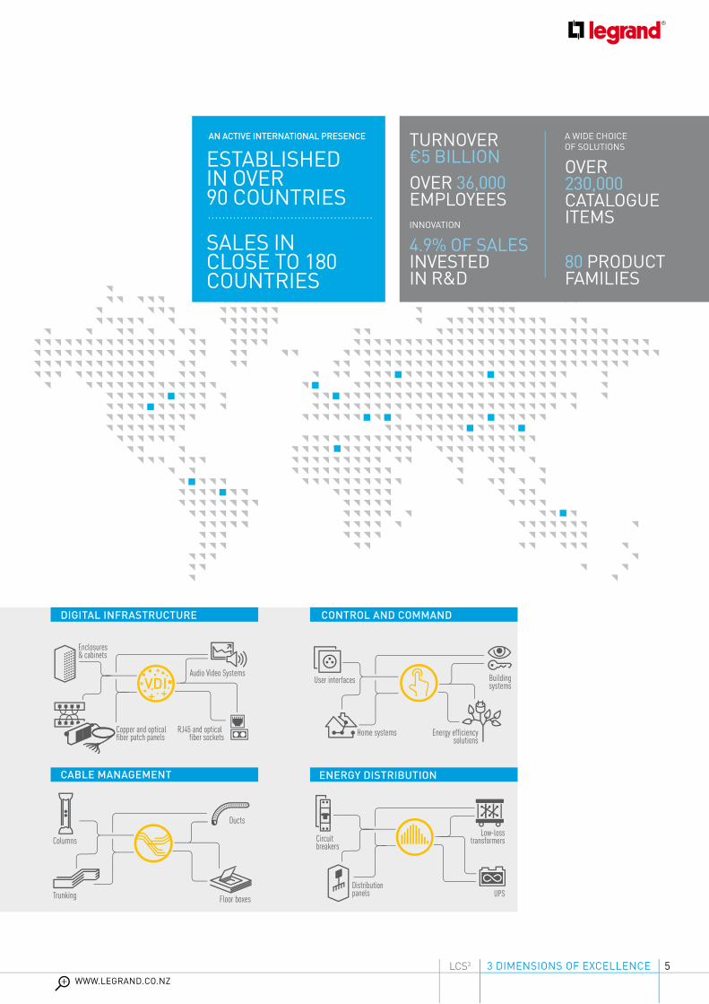
AN ACTIVE INTERNATIONAL PRESENCE
ESTABLISHEDIN OVER90 COUNTRIES
SALES IN CLOSE TO 180COUNTRIES
User interfaces Buildingsystems
Home systems Energy efficiencysolutions
Distributionpanels
Circuit breakers
UPS
Low-losstransformers
Copper and opticalfiber patch panels
Enclosures& cabinets
RJ45 and opticalfiber sockets
Audio Video Systems
Distributionpanels
Circuit breakers
UPS
Low-losstransformers
Copper and opticalfiber patch panels
Enclosures& cabinets
RJ45 and opticalfiber sockets
Audio Video Systems
INNOVATION
4.9% OF SALES INVESTED IN R&D
A WIDE CHOICE OF SOLUTIONS
OVER 230,000 CATALOGUE ITEMS
80 PRODUCT FAMILIES
OVER 36,000 EMPLOYEES
TURNOVER €5 BILLION
CONTROL AND COMMAND
ENERGY DISTRIBUTIONCABLE MANAGEMENT
DIGITAL INFRASTRUCTURE
Floor boxesTrunking
Columns
Ducts

6
Legrand cabling systems currently provide high-quality connectivity to more than 200 million devices. The Legrand Group is a world leader in communication networks for data transmission. Its investment in the
Legrand Group A leading companyfor all your IT networks
development and design of structured cabling systems and solutions has enabled it to expand its offer and achieve the highest level of perfomance. These solutions are ideal for today’s multimedia networks, technologies and applications.
3 DIMENSIONS OF EXCELLENCE
PERFORMANCE SCALABILITY EFFICIENCY

73 DIMENSIONS OF EXCELLENCEWWW.LEGRAND.CO.NZ
LCS3
GLOBAL PLAYERSDATACOM IT
LEGRANDProducts and systems for digital building infrastructures.
• C2G • Electrorack • Estap • Middle Atlantic • Minkels • Quicktron • Raritan • SJ Manufacturing • Valrack
A PORTFOLIO OF SPECIALIST BRANDS

8
Our digital infrastructure expertise
SOLUTIONSFOR STRUCTURED CABLING
• Housing solutions (19” freestanding and wall-mounting cabinets, open racks, PDUs,
micro data centers, etc.)• Copper solutions (New Plug, controlled-access panel, controlled-access RJ45, etc.)• Fibre solutions (Connectors, equipped & modular
panels, bend-insensitive cables, etc.)
LOCAL AREA NETWORKS1Legrand’s complete
global solutions for data
communication perfectly
address the key challenges
for digital networks:
performance, scalability
and efficiency.
8
performance, scalability
and efficiency.
3 DIMENSIONS OF EXCELLENCE
PERFORMANCE SCALABILITY EFFICIENCY

93 DIMENSIONS OF EXCELLENCEWWW.LEGRAND.CO.NZ
LCS3
A WIDE RANGE OF TECHNOLOGIES TO SUIT THE LOCATION AND THE USER EQUIPMENT
• Racks and enclosures• Preterminated audio/video sockets
(HDMI, display port, HD15, USB, RCA, JACK, etc.)• Cords and adaptors
SOLUTIONS FOR STRUCTURED CABLING IN SERVER ROOMS
• Housing solutions (Server cabinets, aisle containment, cooling units and cold corridor, open racks, PDUs, etc.)
• Copper solutions (Preterminated, etc.)
• Fibre solutions (Preterminated, intelligent patching, high-density fibre optic solutions, etc.)
DATA CENTER & SERVER ROOM2 AUDIO VIDEO
SYSTEM3

10
HIGH Performance
1
2
25 Gbps and 40 Gbps Ethernet applications COPPER SYSTEM
40 Gbps and 100 Gbps Ethernet applicationsFIBRE OPTIC SYSTEM
3 MTP/MPO high density and up to Cat. 8 solutionsFIBRE OPTIC & COPPER SYSTEMS
Legrand’s LCS3 system offers you
3 DIMENSIONS OF EXCELLENCE
PERFORMANCE SCALABILITY EFFICIENCY

113 DIMENSIONS OF EXCELLENCEWWW.LEGRAND.CO.NZ
LCS3
COPPER SYSTEMCat. 8 transmission up to 40 Gbps
Cable & connector compliant with ISO/IEC 11801 standards - third edition.
Cat. 8 toolless connector: up to 2500 connection/disconnection cycles
FIBRE OPTIC SYSTEMMTP/MPO solution transmission up to 100 Gbps
High density connection with 12 or 24 fibres compliant with IEEE 802.3ba.
New MPO/MTP fibre optic drawers. Up to 96 LC on 1U.Easy access in order to move, add & change fibres.
Up to 144 LC on 1U. Available in 1U, 2U and 4U.

12
THE NEW toolless Cat. 8 STP CONNECTORS with transmission speed (bit rate) from 25 Gbps to 40 Gbps, are integral to the performance of the new LCS3 system.
• In accordance with ISO/IEC 11801 standard - third edition
• Tested up to 2500 connection/disconnection cycles
• A perfect connection in just a few seconds
Optimum performance with Cat. 8
COPPER SYSTEM
High Performance
with Cat. 8with Cat. 8 with Cat. 8PATENTED DESIGN

133 DIMENSIONS OF EXCELLENCEWWW.LEGRAND.CO.NZ
LCS3
To maximise performance, combine the Legrand Cat. 8 connector together with the Legrand Cat. 8 cable supporting up to 40 Gbps over a single cable.The Cat. 8 cable is terminated with an improved dedicated RJ45 connector which can support future performance.The performance is 4 times better than that of a Cat. 6A cable with up to 2000 MHz bandwidth.
• Double screening to avoid interference and loss of data
• Dedicated to higher capacity in data centers
and equipment rooms
• Compliant with ISO/IEC 11801 standard - third edition
LCS³ 8 LCS2 6A LCS2 6 LCS2 5e
FREQUENCY 2000 MHz 500 MHz 250 MHz 100 MHz
DELIVERY 40 Gbps 10 Gbps 1 Gbps 1 Gbps
WIRING Copper Copper FO Copper FO Copper
CONNECTORS RJ45 RJ45 SC-LC… RJ45 SC-LC… RJ45
MAX. CABLE LENGTH 30 m 100 m variable 100 m variable 100 m
Legrand cable solutionsCOMPONENT SIZES LINK SIZES (CHANNEL)
Supported network protocolCat. 8 STP Cat. 6A STP Cat. 6 UTP Cat. 6 FTP Class I Class EA Class E2000 MHz 500 MHz 250 MHz 250 MHz 2000 MHz 500 MHz 250 MHz 250 MHz40 Giga 10 Giga 1 Giga 1 Giga 40 Giga 10 Giga 1 Giga 1 Giga
Attenuation (dB) Signal loss
LCS3
ISO 11801 Edition 3 1.5 0.130.45 max
0.060.32 max
0.090.32 max 32.7 35.4
42.1 max24.1
29.9 max25.7
30.7 max
Return loss (dB) Resistance to echo
LCS3
ISO 11801 Edition 3 12 17.0514 min
26.5920 min
29.816 min 8 16.4
8 min22.1
10 min38.8
10 min
Next (dB) Resistance todisturbance between pairs(1)
LCS3
ISO 11801 Edition 3 12.9 37.4637 min
56.9346 min
51.346 min 9.8 38.1
29.2 min54
35.3 min53.9
35.3 min

1414
Using PoE technology, devices such as Wi-Fi access points, cameras, etc. can be supplied with power by the Ethernet data cable. The cable combines data and power to supply all the PoE peripherals. Depending on the power available, there are three levels of PoE:
• PoE compliant with IEEE 802.3af -2003
• PoE+ compliant with IEEE 802.3at -2007
• PoE++ compliant with IEEE 802.3bt -2018
All the LCS3 connectorsare PoE+ certified and ready for PoE++
Using PoE technology, devices such as Wi-Fi access points, cameras, etc. can be supplied with power by the Ethernet data cable. The cable combines data and power to supply all the PoE peripherals. Depending on the power available, there are three levels of PoE:
COPPER SYSTEM
High Performance
Using PoE technology, devices such as Wi-Fi access points, cameras, etc. can be supplied

153 DIMENSIONS OF EXCELLENCEWWW.LEGRAND.CO.NZ
LCS3
Due to the high power
in PoE++ the choice of a
high-quality connector
is essential. While
disconnecting, Legrand ’s
high-quality connectors
prevent damage to the
contacts due to the arc
generated.
PoE++ 802.3bt
Trade name IEEE standards Voltage Current drawn
PoE 802.3af-2003 44-57 V 350 mA
PoE+ 802.3at-2009 50-57 V 600 mA
PoE++ pr 802.3bt(*) 50-57 V 600 mA
Trade name Power injector Available power Number of pairs for power supply
Minimum cable category
PoE 15.4 W 12.95 W 2 Cat. 3
PoE+ 30 W 25.5 W 2 Cat. 5e
PoE++ 100 W 70 W (min) 4 Cat. 5e

1616
FIBRE OPTIC SYSTEM
40/100 Gigabit Ethernet
connectivity and cable
High-speed solution
Legrand high-speed solution
MTP systemWith data centers, increased bandwidth has become a priority requirement. The IEEE has therefore introduced the 802.3ba standard for internet connections at 40 Gbps and 100 Gbps and beyond.To answer this need Legrand has introduced the MTP (Multiple-Fibre Push-On/Pull-Off compatible MPO) fibre solution to the catalogue. It guarantees speed, resistance, high performance and high density.
High Performance
MTP is a registered trademark of US Conec Ltd

173 DIMENSIONS OF EXCELLENCEWWW.LEGRAND.CO.NZ
LCS3
With the need to support multiple transmission paths, the MPO-style connector is the connector identified by the IEEE 802.3 ba standard for 40G & 100G transmission (when not using WDM). The terms “MPO” and “MTP” are used interchangeably for this style of connector (MPO = generic name). MTP is an MPO-style connector and is considered to be a better performing connector with lower insertion loss.
Based on the aforementioned standards, all 40/100 Gigabit Ethernet options over multimode fibre use parallel transmission, requiring more than two fibres per channel.
MTP connector feature:• a high-speed connection with 12 fibres (optionally with 24 fibres)• precise and safe connection • optimised cable management• high-density fibres• scalable system for future upgrades• simple maintenance operations• ease of extraction. No complex installation on site - plug and play• the MTP is a 12-core connector. 1 cable = 1 connector
40/100 Gigabit Ethernet
connectivity and cable
With standard active equipment, we need to convert the MTP to LC or SC
High performance
LC® connector
MTP/MPO high performance Multimode high performance Singlemode high performance
Insertion loss / Master IEC 61300-3-4 Up to 0.1 dB typical (all fibres)Up to 0.35 dB maximum (single fibre)
Up to 0.1 dB typical (all fibres)Up to 0.35 dB maximum (single fibre)
Optical return loss Not applicable > 60 dB (8° angle-polished)
The ultra high density connector in our offer is the MTP
Multimode high performance Singlemode high performance
IL Max/Master (Acceptance) Up to 0.15 dB Up to 0.15 dB
IL Max/Random Up to 0.25 dB Up to 0.30 dB
Ave/Master 0.08 dB 0.12 dB
Ave/Random 0.1 dB 0.12 dB
Return loss Up to 35 dB Up to 55 dB
CassetteCassette

18
Common Data Center ApproachesMultimode fibre systems have been the most cost effective fibre solution to use in the data center because the transceivers are much less expensive than single-mode transceivers. Multimode transceivers use a vertical cavity surface emitting laser (VCSEL) light source, which is easy to manufacture and package. Multimode fibre systems have a shorter reach than single-mode systems, however most distances are less than 150 meters; surveys have shown that more than 80% of data centers links are equal to or less than 100 meters. Although single-mode cable is less expensive, factoring in the total system cost of multimode versus single-mode, multimode is still less expensive.
10G 40G 100G (-SR10) 100G (-SR4)
Signalling 10 Gb 10 Gb x 4 10 Gb x 10 25 Gb x 4
Laser Type VCSEL VCSEL Array VCSEL Array VCSEL Array
Fibre Type OM3/OM4 OM3/OM4 OM3/OM4 OM3/OM4
Connector
2 LCs 12-fibre MPO/MTP (2) 12-fibre MPO/MTP or 24-fibre MPO/MTP
12-fibre MPO/MTP
Number of Fibres Needed 2 fibres 8 fibres 20 fibres 8 fibres
Maximum Distance
OM3: 300 m OM4: 550 m
OM3: 100+ m OM4: 150+ m1
OM3: 100+ m OM4: 150 m1
OM3: 70 m OM4: 100 m
1. 150 metres on OM4 requires low-loss connectors. This is discussed in the channel insertion section.
High Performance
Some common approaches used in data centers are summarized in table 6 below. Each approach uses short-wavelength (850 nanometer) transmission over multimode fiber.
Table 6: Common Data Center Approaches Using Short Wavelength Transmission
Note: A 24-fiber MPO can be used instead of the two 12-fiber MPOs
1. 150 meters on OM4 requires low loss connectors. This is discussed in the channel insertion section.
The fiber system should be designed around OM3 or OM4 MMF if there are plans to support applications beyond 10 Gbps. OM3 supports 10 GbE up to 300 meters, but only supports 40 GbE up to 100m. OM3 supports the 100GBASE-SR10 PMD up to 100 meters but only supports 100GBASE-SR4 up to 70 meters so that is another important consideration. OM4 supports 10 GbE up to 550 meters, but only supports 40 GbE up to 150 meters. OM4 supports the 100GBASE-SR10 PMD up to 150 meters but only supports 100GBASE-SR4 up to 100 meters.
If planning to support 40 GbE and/or 100 GbE in the future, the channel cannot be designed for the maximum distances that 10G can be supported. If the data center has distances exceeding 70 meters it is a good idea to use OM4 since OM4 supports 10 GbE through 100 GbE for up to at least 100 meters. Always design for the application that has the most stringent requirements (usually the fastest data rates) even if the application is a future installation.
In addition to selecting the type of fiber, OM3 or OM4, there are several other important considerations when selecting components for a fiber cabling system. These include channel insertion loss, polarity and alignment pins.
Channel Insertion Loss/Loss Budget
The channel insertion loss is made up of the insertion loss (IL) of the cable, specified as decibels per kilometer (dB/km), the insertion loss of all mated connector pairs and the insertion loss of splices in that channel. Referring to table 7, as the data rate increases from 10 Gbps to 40/100 Gbps, the total channel insertion loss or loss budget decreases noticeably.
8
193 DIMENSIONS OF EXCELLENCEWWW.LEGRAND.CO.NZ
LCS3
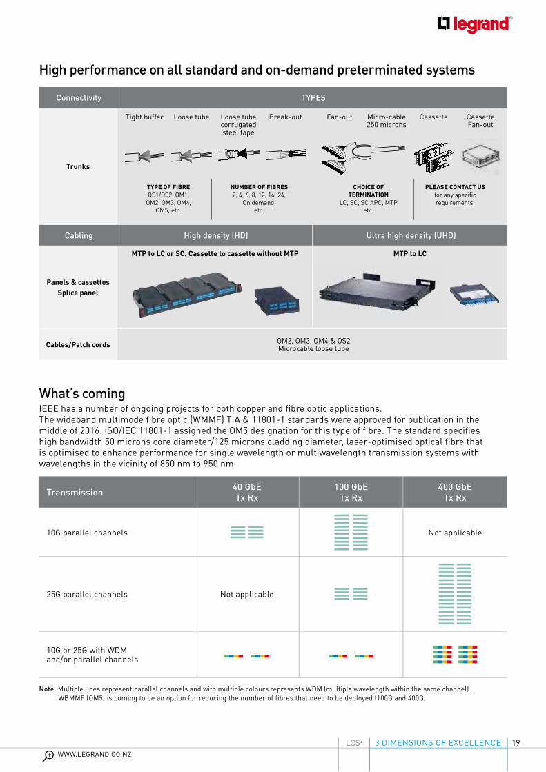
What’s comingIEEE has a number of ongoing projects for both copper and fibre optic applications.The wideband multimode fibre optic (WMMF) TIA & 11801-1 standards were approved for publication in the middle of 2016. ISO/IEC 11801-1 assigned the OM5 designation for this type of fibre. The standard specifies high bandwidth 50 microns core diameter/125 microns cladding diameter, laser-optimised optical fibre that is optimised to enhance performance for single wavelength or multiwavelength transmission systems with wavelengths in the vicinity of 850 nm to 950 nm.
High performance on all standard and on-demand preterminated systems
Connectivity TYPES
Trunks
Cabling High density (HD) Ultra high density (UHD)
Panels & cassettesSplice panel
Cables/Patch cords OM2, OM3, OM4 & OS2Microcable loose tube
Tight buffer Loose tube Loose tubecorrugatedsteel tape
Break-out Fan-out Micro-cable250 microns
Cassette CassetteFan-out
TYPE OF FIBREOS1/OS2, OM1,
OM2, OM3, OM4,OM5, etc.
NUMBER OF FIBRES2, 4, 6, 8, 12, 16, 24,
On demand,etc.
CHOICE OF TERMINATION
LC, SC, SC APC, MTPetc.
PLEASE CONTACT USfor any specific requirements.
MTP to LC or SC. Cassette to cassette without MTP MTP to LC
Transmission 40 GbETx Rx
100 GbETx Rx
400 GbETx Rx
10G parallel channels Not applicable
25G parallel channels Not applicable
10G or 25G with WDM and/or parallel channels
Note: Multiple lines represent parallel channels and with multiple colours represents WDM (multiple wavelength within the same channel). WBMMF (OM5) is coming to be an option for reducing the number of fibres that need to be deployed (100G and 400G)

20
SLIDING CASSETTE:EASIER MAINTENANCE
INNOVATIVE MODULARCASSETTE SYSTEM
FAST PUSH-BUTTONEXTRACTION
Scalability &Maintenance
The NEW TOOLLESS CONNECTORS with toolless fast connection are available in all categories for installation both on patch panels and in the workstation. A perfect connection can be obtained in a few seconds, guaranteeing optimum performance of the link from the patch panel to the workstation. They are colour-coded so their category can be safely identified:
• Cat. 5e: grey
• Cat. 6: blue
• Cat. 6 A: yellow
• Cat. 8: aqua
COPPER SYSTEM
RJ 45 Connectors
1
2
3
3 DIMENSIONS OF EXCELLENCE
PERFORMANCE SCALABILITY EFFICIENCY
PATENTED DESIGN

213 DIMENSIONS OF EXCELLENCEWWW.LEGRAND.CO.NZ
LCS3
New Toolless connector connection phases
New systems to facilitate wiring and installation and increase the data transfer
speed with both the copper solution and the fibre optic solution.
1
3
5
2
4
6
Take the wire housing
Separate and insert the pairs
Install the wire housing without pushing
Pass the cable through the back of the wire housing
Cut the pairs
Push down the lever and lock the connector

22
• Sliding cassettes: easier maintenance• Fast push-button extraction • Innovative modular cassette system• Easy maintenance: Remove connectors
without disconnecting the cords • Easy to mix with Legrand fibre optic
solutions
Flat patch panel solution, 48 unit ports
Block of 12 connectors for patch panel
The new patch panels have been designed and produced to optimise space, with up to 48 ports per unit and make maintenance and future upgrades easier. They are available in both flat and angled versions. They have a quick system for pulling out the unit and an innovative cable guiding system for tidy and easy cable management.
Patch Panels
PATENTED DESIGN
Scalability & Maintenance

233 DIMENSIONS OF EXCELLENCEWWW.LEGRAND.CO.NZ
LCS3
New QUICK-FIX system
Innovative new quick-fixing solution:• Push and connect system• Automatic earth connection • In-rack cabling optimised• New accessory for patch cords with rotating
system for angle adjustment and label holder
Compatible with all panels (Flat, angled, HD)
PATENTED DESIGN

24
Patch panels with an angled design which allows the cable to run into each side of the rack, creating a correct cable radius of curvature. This avoids the need to manage the cables horizontally, and allows the patch cords to be carried directly in the vertical cavities.
Angled patch panel solution from 24 to 48 ports per unit
High density - This supplies up to 48 ports in a single unit to take up less space in the rack
Scalability & Maintenance
Strong steel structure Cover for airflow management

253 DIMENSIONS OF EXCELLENCEWWW.LEGRAND.CO.NZ
LCS3
Also available in the 24-port version
Simple and efficient Identification of the ports
3 DIMENSIONS OF EXCELLENCELCS3
Tidy cable management Quick-fix system

26
Scalability &Maintenance
Completely renovated and redesigned fibre optic panels
& drawers in high and very high density versions from 96
connectors per unit to 144 connectors per unit. Panels with
sliding drawers and fast push-button system to facilitate
upgrade and maintenance operations.upgrade and maintenance operations.
Fibre opticpanelspanels
Fibre opticpanels
Fibre opticFibre opticpanels
Fibre optic

273 DIMENSIONS OF EXCELLENCEWWW.LEGRAND.CO.NZ
LCS3
HD MODULAR PANELS
273 DIMENSIONS OF EXCELLENCEWWW.LEGRAND.CO.NZ
LCS3
• Innovative new quick- fixing solution
• Possible to add splicing cassette with perfectly adapted coiling space
• Mixture of fibre/copper on modular panel in drawer
MODULAR PANELS
• Possible to change modular blocks, blank panel, MTP adaptor
• Splice trays to be added if necessary - up to 4 containing 96 LC fibres

2828
Fibre optic panels
Scalability & Maintenance
PUSH-BUTTON CASSETTE Fast push-button system to facilitate upgrade and maintenance operations
SPLICING CASSETTE
COPPER CASSETTE
PRETERMINATED CASSETTE

293 DIMENSIONS OF EXCELLENCEWWW.LEGRAND.CO.NZ
LCS3 293 DIMENSIONS OF EXCELLENCELCS3
HD MODULAR PANELS
• Cassettes slide in from front & rear
• Fast push-button on cassette
• Splicing cassette which takes all modular blocks
• Mixture of fibre/copper on cassette panel
• Trunk & cord management system
MODULAR PANELS
• Innovative new quick- fixing solution
• Modular blocks to adapt to modular panel or drawer: LC, SC, ST, LC, APC, SC APC
• Possible to add modular blocks, blank panel, MTP adaptor
PATENTED DESIGN
30
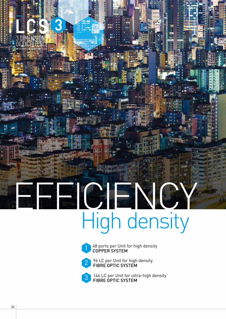
48 ports per Unit for high density COPPER SYSTEM
96 LC per Unit for high densityFIBRE OPTIC SYSTEM
144 LC per Unit for ultra-high densityFIBRE OPTIC SYSTEM
EFFICIENCYHigh density
3 DIMENSIONS OF EXCELLENCE
1
2
3
PERFORMANCE SCALABILITY EFFICIENCY

313 DIMENSIONS OF EXCELLENCEWWW.LEGRAND.CO.NZ
LCS3
High-density patch panel. Ithas changed from 24 to 48ports, guaranteeing a reductionin space occupied and makingfuture upgrades easier.Designed to house 4 blocks of 12 connectors each.
COPPER SYSTEMPatch panel HD solution up to 48 ports per unit
Fast push-button extraction
Quick-fix system
Single block with 12 connectors
New tidy cable management
Since different network architectures such as top-of-rack, end-of-row and middle-of-row require different cabling densities, passive equipment needs to adapt perfectly to the active network. The LCS3 HD cassette panel provides
a mixed-media structured cabling system to support any configuration. Legrand LCS3 offers an innovative UHD patch panel designed to house up to 144 connections in 1 U distributed between 6 individual modules of 24 fibres each.
Each module accepts incoming fibres both from MTP® trunk cables and via predetermined components. Predetermined cables are available both as breakout cables and as distribution cables.
FIBRE OPTIC SYSTEMVery High density up to 144 LC/1U
• Up to 144 LC/1U• 1U, 2U, 4U• Microcable preterms
• Up to 96 LC/1U• Mixture of fibre & copper• Microcable preterms
ULTRA HIGH DENSITY UHD HIGH DENSITY HD
EFFICIENCY
Preterminated: The fibre optic cable termination is the addition of connectors to each optical fibre in a cable. The connectors are assembled in our factories

32
Easy installationLegrand has launched an innovative connection system to make simple, affordable fibre connections.
1 PREPARE THE FIBRE
SMART SPLICER
• Easy to handle: one of the smallest tools in the market
• Easy to use: simple program with easy intuitive feedback
• Low cost: quick return on investment
• Best-in-class connection with 25-year warranty
• Legrand-coded pigtail connectors
• Pigtails: OM2, OM3, OM4, OS2, LC, SC, LC APC, SC APC
3 DIMENSIONS OF EXCELLENCE
PERFORMANCE SCALABILITY EFFICIENCY
SMART SPLICER
• Easy to handle: one of the smallest tools in the market
• Easy to use: simple program with easy intuitive feedback
• Low cost: quick return on investment
PATENTED DESIGN

333 DIMENSIONS OF EXCELLENCEWWW.LEGRAND.CO.NZ
LCS3
2 CLEAVE THE FIBRE 3 SPLICE THE FIBRE 4 PROTECT THE FIBRE (heat)
INSERTION LOSS LED
GREEN: < 0.1 dB
ORANGE: 0.1 dB < x < 0.2 dB
RED: > 0.2 dB

34
Legrand LCS3 has an extensive portfolio of enclosures and aisle containment systems for your data center and/or server room. The Legrand LCS3 is ideal for the installation of (blade) servers, switches, patch panels, routers and storage equipment. Modularity and flexibility are always key in the design of our products.
Performance, scalable & efficient
solutions
LCS3 DATA CENTEREnclosure & aisle containment

353 DIMENSIONS OF EXCELLENCEWWW.LEGRAND.CO.NZ
LCS3
LCS3 server-and-network rack The server-and-network racks are versatile and modularly constructed. Which type of rack is most suitable depends ultimately on its application. The server-and-network racks are available in varying heights, widths and depths.
The 600 mm wide rack is a compact rack with a high carrying capacity on a small surface. The 800 mm wide rack is ideal for to patching, network and server equipment with enough space for power and network cabling.
Airflow optimisation Data centers are increasingly using energy-efficient cooling techniques such as free cooling and fresh air cooling. The first step in this process is separating the warm and cold air using aisle containment solutions. The next step is airflow optimisation in the rack. This step, however, is often not fully or effectively
implemented, although it is the next step in energy-efficient data centers. Airflow optimisation is also important for the server, network and storage equipment to work properly, for temperature control and for the general stability of a data center.
Using airflow optimisation you can achieve the highest levels of
Cable brush Cable entry foam Cable entry plate
airtightness. The side sealing plate and the side sealing panel are covered with foil. Every assembly opening in the side sealing panel is still usable, but all unused openings are sealed with foil to prevent air leakage. The base and roof plates have an identical level of airtightness. Special foam pieces are even placed around the rails on the base.

36
Top-of-rack cabling system
From building to cabinetLEGRAND LCS3 cable trays can be used for optimum guidance of cables to the cabinet. Cable trays are flexible, modular, easily installable and can be integrated seamlessly in the cabinet. Because this cable system is fixed directly onto the cabinets, it becomes independent of its surroundings. Thus, if the data center expands, the cable management can expand with it without requiring any changes to the construction of the building, unlike ceiling anchoring systems.
From rack row to rack row Cable bridges can be used for crossing a cold or warm corridor. The cable bridge can be used for both small and wide cable trays. These can also be used in combination with aisle containment. Because cable bridges are telescopic, no sawing is required in the data center. This helps avoid outages of critical equipment.
From rack to rackCable trays can also be used for cabling from rack to rack. In this case cables do not run horizontally through the racks but are guided over the top, across the roof towards the neighbouring racks.
From building to cabinetLEGRAND LCS3 cable trays can be used for optimum guidance of cables
From rack row to rack row Cable bridges can be used for crossing a cold or warm corridor.
From rack to rackCable trays can also be used for cabling from rack to rack. In this case cables do not run horizontally
373 DIMENSIONS OF EXCELLENCEWWW.LEGRAND.CO.NZ
LCS3
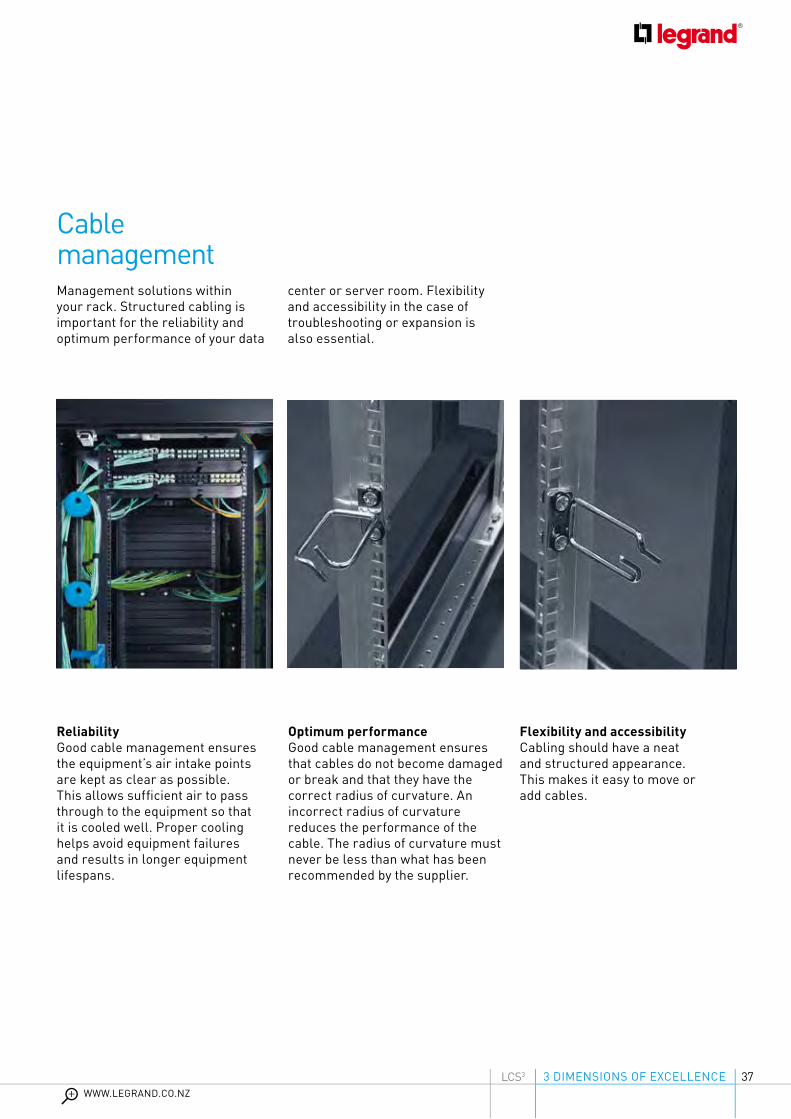
Cable management Management solutions within your rack. Structured cabling is important for the reliability and optimum performance of your data
center or server room. Flexibility and accessibility in the case of troubleshooting or expansion is also essential.
Optimum performanceGood cable management ensures that cables do not become damaged or break and that they have the correct radius of curvature. An incorrect radius of curvature reduces the performance of the cable. The radius of curvature must never be less than what has been recommended by the supplier.
ReliabilityGood cable management ensures the equipment’s air intake points are kept as clear as possible. This allows sufficient air to pass through to the equipment so that it is cooled well. Proper cooling helps avoid equipment failures and results in longer equipment lifespans.
Flexibility and accessibilityCabling should have a neat and structured appearance. This makes it easy to move or add cables.

38
By cooling your data center in the right manner, you can significantly reduce your energy spending. Minkels has developed an extensive range of energy-efficient cooling solutions.
Energy bill savings
Aisle Containment Performance,
efficiency & scalability
393 DIMENSIONS OF EXCELLENCEWWW.LEGRAND.CO.NZ
LCS3
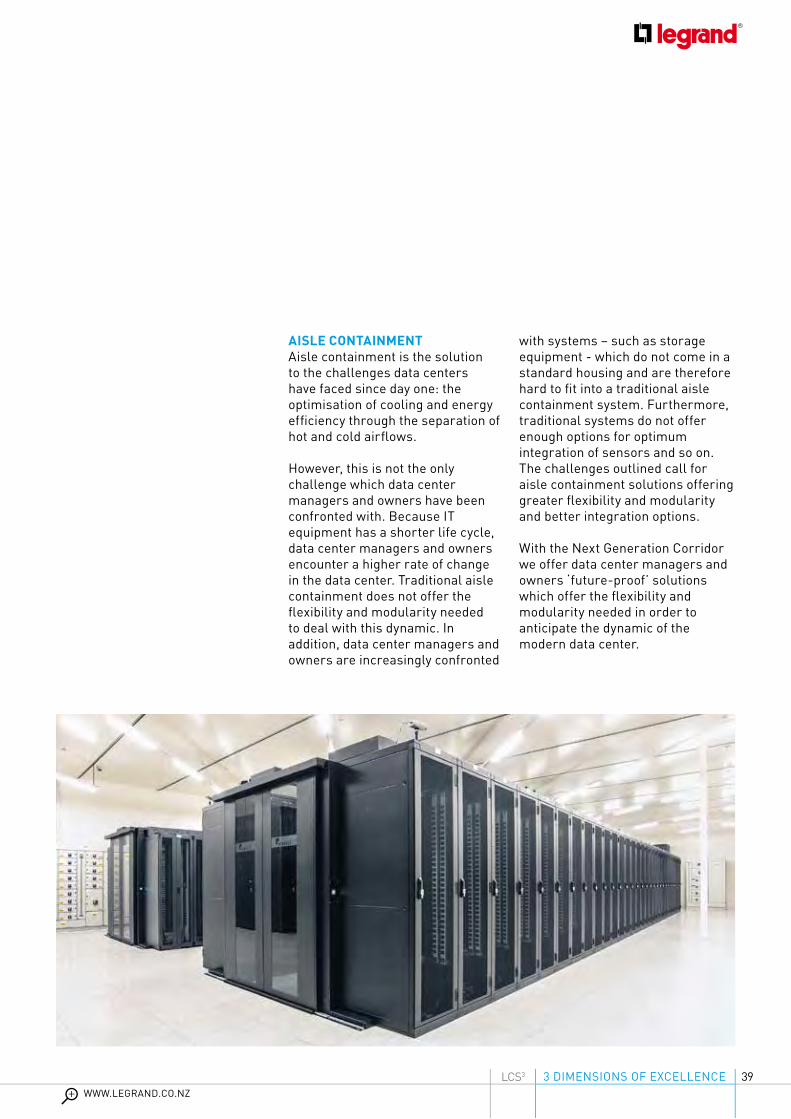
AISLE CONTAINMENT Aisle containment is the solution to the challenges data centers have faced since day one: the optimisation of cooling and energy efficiency through the separation of hot and cold airflows.
However, this is not the only challenge which data center managers and owners have been confronted with. Because IT equipment has a shorter life cycle, data center managers and owners encounter a higher rate of change in the data center. Traditional aisle containment does not offer the flexibility and modularity needed to deal with this dynamic. In addition, data center managers and owners are increasingly confronted
with systems – such as storage equipment - which do not come in a standard housing and are therefore hard to fit into a traditional aisle containment system. Furthermore, traditional systems do not offer enough options for optimum integration of sensors and so on. The challenges outlined call for aisle containment solutions offering greater flexibility and modularity and better integration options.
With the Next Generation Corridor we offer data center managers and owners ‘future-proof’ solutions which offer the flexibility and modularity needed in order to anticipate the dynamic of the modern data center.

40
NEXT GENERATION CORRIDORS (rack-dependent) Minkels was the first data center supplier in Europe to introduce the Corridor solutions commercially. Since then, these solutions have been used to separate the airflows of many a data center in an energy-efficient manner. Next Generation Corridor is the ultimate answer to the ever-increasing demand for flexible and modular solutions. The Next Generation Corridor takes modular thinking and energy-efficient data center design to a higher level.
40

413 DIMENSIONS OF EXCELLENCEWWW.LEGRAND.CO.NZ
LCS3
2013
EUROPEAN RACKS & CABINETSENTREPRENEURIAL COMPANY OF THE YEAR AWARD
Important features of the Next Generation Corridor are:
MODULARITYThrough the highly modular concept of the Next Generation Corridor, Minkels offers extensive ways to implement a Corridor solution in a phased and thus cost-efficient manner.
FLEXIBILITYBecause of its modular design, the Next Generation Corridor is flexible and thus can be adapted to fit the specific building environment.
EASE OF INSTALLATIONModularity in the construction details ensures that the solution is easily and cost-efficiently installed.
ENERGY EFFICIENCYWith the Next Generation Corridor, Minkels offers a solution which is more energy-efficient than other aisle containment models on the market.
OPTIMUM INTEGRATIONThe Next Generation Corridor can be integrated with row-based cooling systems which bring cooling close
to the heat source, but also with more traditional forms of cooling which require a raised floor. In addition, this concept offers plug & play integration with e.g. fire detection and suppression systems, monitoring sensors and access control.

4242
Micro data center
The MiniCubeProfessionalising the IT infrastructure With the adoption of cloud computing, many companies are now looking to reduce the size of their server rooms and save energy costs. Do you have fewer applications running from your in-house server room than before? Do you only want to house your business critical information on site? Then the time has come to deploy an efficient, turnkey micro
One Catalogue number, one solution
data center. Whether you want to access data more quickly - low latency - or you want to optimise your server room, the MiniCube is the ideal solution. The MiniCube has everything you need for a full data center: housing, power supply, monitoring and cooling, all in a compact system. The MiniCube is fully preconfigured and truly plug-and-play.
Advantages• Reliable and efficient solution for server rooms• No dependency on the building, easy to deploy• Efficient cabinets or racks for your IT infrastructure• Use of proven technologies• Turnkey solution, including installation and start-up

433 DIMENSIONS OF EXCELLENCEWWW.LEGRAND.CO.NZ
LCS3
Local Area Network
LCS3 CONNECTIVITY RACKMighty Mo 20 4-post racks provide greater flexibility and optimum efficiency in any data center. The fixed racks provide an economical mounting platform for switches and servers while the adjustable rack allows all 4 mounting rails to be adjusted even after the rack has been fastened to the floor.
LCS3 WALL ENCLOSUREThe basic frame is made up of a wall-mounting plate with integrated strain relief bar, four depth rails, two cable-entry plates (base and top) and a set of 19-inch rails. The assembly consists of two equal top and base panels with ventilation slots to the rear, two equal side panels and a safety glass door with an EK-333 cylinder lock with grip.
LCS3 CABLING RACKGiven how quickly IT technology evolves, a flexible, future-proof concept is essential. The LCS3 cabling rack is specifically designed to meet these needs and stands out due to its versatility, ease of installation and ease of use. The LCS3 cabling rack is a multifunctional system, specifically designed for ease of installation. The system is ultimately suitable
Front and rear waterfalls allow for equipment patching and server patching. All styles of Mighty Mo 20 vertical manager can be mounted front or rear, and airflow baffles can be mounted to manage the airflow of side-breathing equipment.
for housing UTP patch panels, glass drawers, telephone panels, switches, routers and other IT equipment. Of course it is also possible to include a small number of servers.

44
GENERAL CHARACTERISTICS
STANDARDS
SAFETY
POWER SUPPLY
• Anodised aluminium body: Lightweight rigid high-end material
• Modular design: Expandable outlet and function modules
IEC 60950 - Information technology equipment – Safety
IEC 60297-3 - Dimensions of mechanical structures
of the 482.6 mm (19 in) series
IEC 60320-2-2 - Interconnection couplers (C13 and C19)
for household and similar equipment
IEC 60884-1 - Plugs and socket outlets for household
and similar purposes (France, Belgium and Germany)
BS 1363-2 - British standard plugs and socket outlets
IEC 60309 - Plugs, socket outlets and couplers for industrial
purposes
Certification: CE, TSE, CCC
Environmentally-friendly productsEco-friendly design
• High electrical safety rating • High-quality connection• Outlets equipped with safety shutter• Cord Locking System
• PDUs integrate local and international outlet types
• 16 A to 32 A single-phase or three-phase
FOR DATA CENTERS/SERVER ROOMS Used in server cabinets where:- there is a high density of active equipment- electrical distribution quality is crucial
ZERO-U
12 CATALOGUE NUMBERS
This new PDU offer combines Legrand’s quality and innovation with a wide range of applications. A standalone solution, this range integrates seamlessly into any installation and ensures compliance with applicable standards.
A wide universal range
PDUSSolutions for any configuration
ZERO-U PDUs
FOR VERTICAL INSTALLATION

453 DIMENSIONS OF EXCELLENCEWWW.LEGRAND.CO.NZ
LCS3
19” 1-U PDUs 10” 1-U PDUs
FOR DATA CENTERS/SERVER ROOMS AND COMPUTER ROOMSUsed in server and cabling cabinets where:- there is a low density of active equipment to be powered- ease of installation is an advantage
FOR SMALL IT ENVIRONMENTSMainly used in small-scale commercial applications where there is a limited number of IT points and a 10” cabinet is sufficient:- Small businesses, freelance professions, administrative services, etc.
3 CATALOGUE NUMBERS26 CATALOGUE NUMBERS
19” 10”
1U
FOR VERTICAL OR HORIZONTAL INSTALLATION HORIZONTAL PDU
1U

46
CORD LOCKING SYSTEMVery easy to identify thanks to the orange buttons next to each outlet
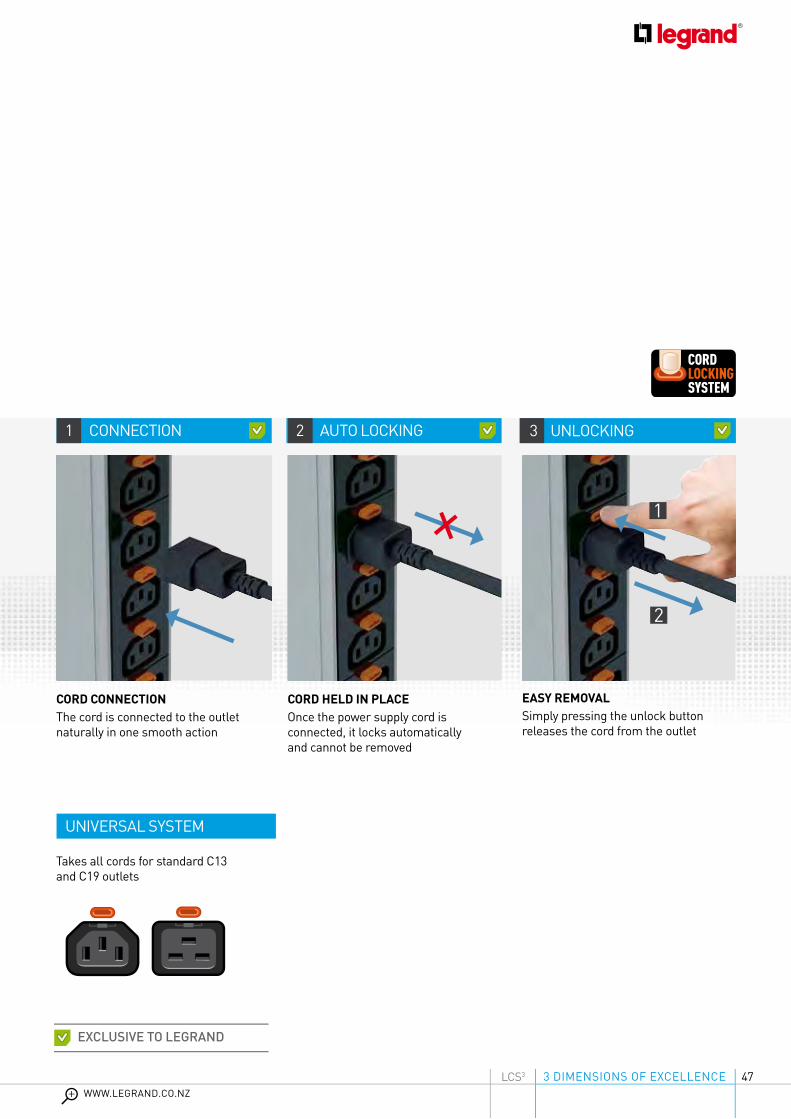
Cord Locking SystemInnovation at the heart of PDUs
AN INNOVATIVE TECHNICAL SOLUTION
A major addition to the range and exclusive to Legrand, C13 and C19 outlets have a power supply cord locking system which prevents accidental disconnection and guarantees absolute safety.
For C13 & C19 sockets
473 DIMENSIONS OF EXCELLENCEWWW.LEGRAND.CO.NZ
LCS3
CORD CONNECTIONThe cord is connected to the outlet naturally in one smooth action
Takes all cords for standard C13 and C19 outlets
CORD HELD IN PLACEOnce the power supply cord is connected, it locks automatically and cannot be removed
EASY REMOVALSimply pressing the unlock button releases the cord from the outlet
EXCLUSIVE TO LEGRAND
1 CONNECTION 2 AUTO LOCKING 3 UNLOCKING
UNIVERSAL SYSTEM
1
2

48
CABLE ORIENTATION 330° rotating cable entry for perfect cable orientation without needing to access the cabinet.
3
6
5
1
2
4
330 °
ZERO-U PDUS Innovation & performance
1 CABLE ENTRY
Every detail matters! Legrand’s unique and novel innovations, which include safety features, simplified setup and integration, and consumption indicators, help ensure optimum performance for the Zero-U range of PDUs.
Exclusive innovations

493 DIMENSIONS OF EXCELLENCEWWW.LEGRAND.CO.NZ
LCS3
ENHANCED PROTECTIONCircuits protected by MCB. Holder with projecting edges to avoid unintended operation (a cover can be added on request).
COLOUR-CODED CIRCUITSEach circuit is colour-coded, with the colour clearly visible on the front panel and along the edges of a module.The colour corresponds to the specific MCB protecting the circuit.
CONSUMPTION INDICATORConsumption is measured to ensure better installation management:• Balancing circuits• Display of available capacity• Power features and overload prevention
16/32 A single-phase
16/32 A three-phase
There are multiple solutions depending on power supply requirements
Zero-U PDUs simply clip vertically into slots on the mounting frame without the need for any screws.
VERTICAL INSTALLATION
EXCLUSIVE TO LEGRAND
2 MCB HOLDER 3 IDENTIFICATION 4 AMMETER
5 POWER SUPPLY 6 SCREWLESS MOUNTING
50
1
4
23
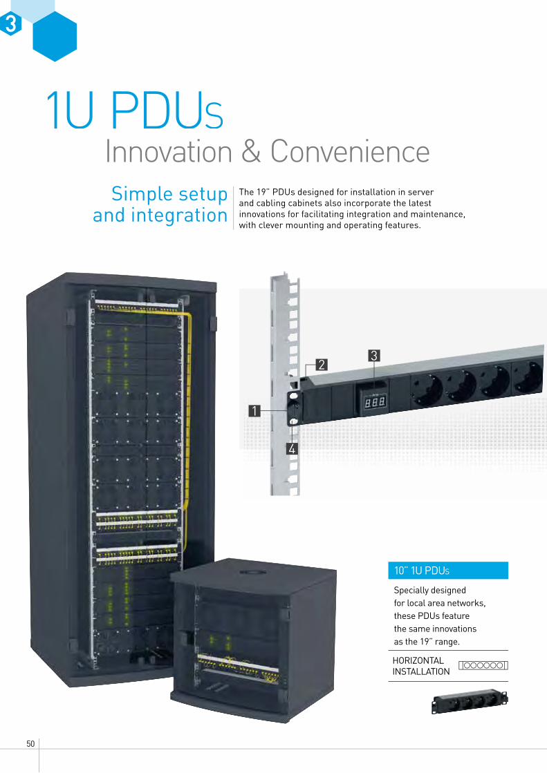
10” 1U PDUS
Specially designed for local area networks, these PDUs feature the same innovations as the 19” range.
1U PDUS
The 19” PDUs designed for installation in server and cabling cabinets also incorporate the latest innovations for facilitating integration and maintenance, with clever mounting and operating features.
Simple setup and integration
Innovation & Convenience
HORIZONTAL INSTALLATION

513 DIMENSIONS OF EXCELLENCEWWW.LEGRAND.CO.NZ
LCS3
TOOLLESS INSTALLATIONQuick, toolless fixing on the 19” uprights. No screws or nuts required.
OPTIMISED SPACECables are held firmly in place by a cable guide.
CHANGE OF POSITIONThe ammeter can be rotated 90° to ensure easy reading regardless of mounting position (horizontal or vertical).
HORIZONTAL OR VERTICAL
Designed for horizontal toolless mounting, 1U PDUs can also be mounted vertically simply by rotating the mounting brackets. Vertical mounting requires a bolt and nut to fix the PDU firmly to the upright.
90 °
EXCLUSIVE TO LEGRAND
1 QUICK FIXING 2 CABLE GUIDE 3 AMMETER
4 MOUNTING SUPPORTS
HORIZONTAL OR VERTICAL
INSTALLATION

52
21
Compatible with all the PDUs in the range, the complementary accessories allow you to control the power supply at the outlets and protect against overvoltages.
Enhanced safety and control
ProtectionaccessoriesProtectionaccessoriesProtection

533 DIMENSIONS OF EXCELLENCEWWW.LEGRAND.CO.NZ
LCS3
3
CONTROLLING ACCESS TO THE POWER SUPPLYLocking caps are used to lock access to a socket. A special key is required to unlock it.
Locking caps available for the following standard socket outlets: C13, C19, German, French-Belgian, British
UNINTERRUPTIBLE PROTECTIONThe surge protection module protects equipment against overvoltages and incorporates hot swap technology. It can be used to replace a used module without interrupting the power supply to the other equipment connected to the PDU.
This is an essential accessory for business servers which need continuous protection. The module is equipped with a warning LED which indicates when it needs replacing.
1 OUTLET LOCKING CAP
2 SURGE PROTECTION DEVICE
EXCLUSIVE TO LEGRAND

54
Support you can rely on
It takes more than just sophisticated technological solutions to manage international projects successfully. What is really needed is the comprehensive and expert support of an experienced partner: from project design and choice of the right solution through to on-site logistics, installation and configuration, including any subsequent troubleshooting and maintenance.
Legrand is ideally placed to offer this type of support, as all its products and solutions are developed and produced in close proximity to its customers. It also offers a wide range of special services and support tools which create genuine added value by making customers' day-to-day business significantly easier. This support is available at every stage of the project, whatever the customer touchpoint.

553 DIMENSIONS OF EXCELLENCEWWW.LEGRAND.CO.NZ
LCS3
01 A diverse range of digital tools including websites, social media and news feeds so you can contact Legrand at any time and stay up to date with all essential news that is relevant to your projects.
02 Personal advice, technical support and documents, white papers, catalogues and e-catalogues, mobile apps, and software to help with product choice or drawing up bills of materials.
03 Training courses covering actual product expertise as well as the latest developments in technology, standards and regulations. Customised training courses available on request, either face to face or in virtual online classes.
04 Configurators, project software and AutoCAD libraries for project design, open for integration into existing software solutions wherever possible.
56
Evolution of standard11801 Edition 3 - 2018
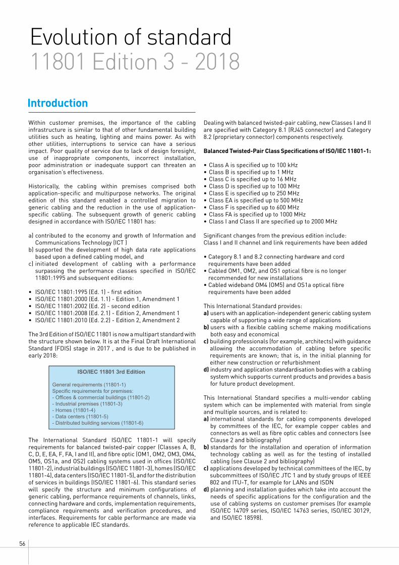
Within customer premises, the importance of the cabling infrastructure is similar to that of other fundamental building utilities such as heating, lighting and mains power. As with other utilities, interruptions to service can have a serious impact. Poor quality of service due to lack of design foresight, use of inappropriate components, incorrect installation, poor administration or inadequate support can threaten an organisation’s effectiveness.
Historically, the cabling within premises comprised both application-specific and multipurpose networks. The original edition of this standard enabled a controlled migration to generic cabling and the reduction in the use of application-specific cabling. The subsequent growth of generic cabling designed in accordance with ISO/IEC 11801 has:
a) contributed to the economy and growth of Information and Communications Technology (ICT )
b) supported the development of high data rate applications based upon a defined cabling model, and
c) initiated development of cabling with a performance surpassing the performance classes specified in ISO/IEC 11801:1995 and subsequent editions:
• ISO/IEC 11801:1995 (Ed. 1) - first edition• ISO/IEC 11801:2000 (Ed. 1.1) - Edition 1, Amendment 1• ISO/IEC 11801:2002 (Ed. 2) - second edition• ISO/IEC 11801:2008 (Ed. 2.1) - Edition 2, Amendment 1• ISO/IEC 11801:2010 (Ed. 2.2) - Edition 2, Amendment 2
The 3rd Edition of ISO/IEC 11801 is now a multipart standard with the structure shown below. It is at the Final Draft International Standard (FDIS) stage in 2017 , and is due to be published in early 2018:
The International Standard ISO/IEC 11801-1 will specify requirements for balanced twisted-pair copper (Classes A, B, C, D, E, EA, F, FA, I and II), and fibre optic (OM1, OM2, OM3, OM4, OM5, OS1a, and OS2) cabling systems used in offices (ISO/IEC 11801-2), industrial buildings (ISO/IEC 11801-3), homes (ISO/IEC 11801-4), data centers (ISO/IEC 11801-5), and for the distribution of services in buildings (ISO/IEC 11801-6). This standard series will specify the structure and minimum configurations of generic cabling, performance requirements of channels, links, connecting hardware and cords, implementation requirements, compliance requirements and verification procedures, and interfaces. Requirements for cable performance are made via reference to applicable IEC standards.
Dealing with balanced twisted-pair cabling, new Classes I and II are specified with Category 8.1 (RJ45 connector) and Category 8.2 (proprietary connector) components respectively.
Balanced Twisted-Pair Class Specifications of ISO/IEC 11801-1: • Class A is specified up to 100 kHz• Class B is specified up to 1 MHz• Class C is specified up to 16 MHz• Class D is specified up to 100 MHz• Class E is specified up to 250 MHz• Class EA is specified up to 500 MHz• Class F is specified up to 600 MHz• Class FA is specified up to 1000 MHz• Class I and Class II are specified up to 2000 MHz
Significant changes from the previous edition include:Class I and II channel and link requirements have been added
• Category 8.1 and 8.2 connecting hardware and cord requirements have been added
• Cabled OM1, OM2, and OS1 optical fibre is no longer recommended for new installations
• Cabled wideband OM4 (OM5) and OS1a optical fibre requirements have been added
This International Standard provides:a) users with an application-independent generic cabling system
capable of supporting a wide range of applicationsb) users with a flexible cabling scheme making modifications
both easy and economicalc) building professionals (for example, architects) with guidance
allowing the accommodation of cabling before specific requirements are known; that is, in the initial planning for either new construction or refurbishment
d) industry and application standardisation bodies with a cabling system which supports current products and provides a basis for future product development.
This International Standard specifies a multi-vendor cabling system which can be implemented with material from single and multiple sources, and is related to:a) international standards for cabling components developed
by committees of the IEC, for example copper cables and connectors as well as fibre optic cables and connectors (see Clause 2 and bibliography)
b) standards for the installation and operation of information technology cabling as well as for the testing of installed cabling (see Clause 2 and bibliography)
c) applications developed by technical committees of the IEC, by subcommittees of ISO/IEC JTC 1 and by study groups of IEEE 802 and ITU-T, for example for LANs and ISDN
d) planning and installation guides which take into account the needs of specific applications for the configuration and the use of cabling systems on customer premises (for example ISO/IEC 14709 series, ISO/IEC 14763 series, ISO/IEC 30129, and ISO/IEC 18598).
Introduction
ISO/IEC 11801 3rd Edition
G eneral req uirements ( 118 01- 1)Specific requirements for premises:- Offices commercial buildings (11801-2)- Industrial premises (11801-3)- Homes (11801-4)- Data centers ( 118 01- 5)- Distributed building services (11801-6)

573 DIMENSIONS OF EXCELLENCEWWW.LEGRAND.CO.NZ
LCS3
Physical layer requirements for the applications listed in Annex E have been analysed to determine their compatibility with the cabling classes specified in this standard. These application requirements, together with statistics concerning the topology of premises and the model described in ISO/IEC 11801-2 clause 8.2, have been used to develop the requirements for Classes A to FA and fibre optic cabling systems.
In offices, horizontal balanced cabling should now be designed to provide minimum Class E, and minimum Class EA is recommended to support applications with data rates exceeding 1 Gigabit/sec.
Scopes
Scope of ISO/IEC 11801-1: Generic cabling for customer premises – Part.1 General requirements
This International Standard specifies requirements that are common to the other parts of the ISO/IEC 11801 series. Cabling specified by this standard supports a wide range of services including voice, data, and video that may also incorporate the supply of power. This International Standard specifies: a) The fundamental structure and configuration
of generic cabling requirements within the type 400 premises defined by the other standards in the ISO/IEC 11801 series
b) channel transmission and environmental performance requirements
c) link performance requirements d) component performance requirements,
referring to available International Standards for 404 components and test methods where appropriate
e) test procedures to verify compliance with the cabling transmission performance requirements 406 of the 11801 series documents.
Note: This International Standard does not contain specific compliance requirements. The cabling design documents supported by ISO/IEC 11801-1 incorporate the requirements of this standard as part of their individual compliance requirements. In addition, ISO/IEC 11801-1 provides information regarding the applications supported by the cabling channels. ISO/IEC 11801-1 has taken into account requirements specified in the application standards listed in Annex E.
Scope of ISO/IEC 11801-2 – Generic cabling for customer premises – Part.2 Office premises
This International Standard specifies generic cabling for use within office premises, which may comprise single or multiple buildings on a campus. It covers balanced cabling and fibre optic cabling. ISO/IEC 11801-2 is optimised for premises where the maximum distance over which telecommunications services can be distributed is 2000 m. The principles of this International Standard may be applied to larger installations. Cabling specified by this standard supports a wide range of services including voice, data, and video that may also
incorporate the supply of power. This International Standard specifies directly or via reference to ISO/IEC 11801-1:
a) the structure and minimum configuration for generic cabling within office premises
b) the interfaces at the telecommunications outlet (TO) c) the performance requirements for cabling links and channels d) the implementation requirements and options e) the performance requirements for cabling components f) the compliance requirements and verification procedures.
ISO/IEC 11801-2 has taken account of the requirements specified in application standards listed in ISO/IEC 11801-1:201X, Annex E.
Safety (e.g. electrical safety and protection and fire) and Electromagnetic Compatibility (EMC) requirements are outside the scope of this International Standard, and are covered by other standards and by regulations. However, information given by this standard may be of assistance.
Scope of ISO/IEC 11801-6 – Generic cabling for customer premises – Part. 6 Distributed building services.
Source: ISO/IEC 11801-1 (2017)
The figure shows the schematic and contextual relationships between the standards relating to information technology cabling produced by ISO/IEC JTC 1/SC 25, namely the ISO/IEC 11801 series of standards for generic cabling design, standards for the installation, operation and administration of generic cabling and for testing of installed generic cabling.
The life expectancy of generic cabling systems can vary depending on environmental conditions, supporting applications, ageing of materials used in cables, and other factors, such as access to pathways (campus pathways are more difficult to access than building pathways). With appropriate choice of components, generic cabling systems meeting the requirements of this International Standard are expected to have a life expectancy of at least ten years.
ISO/IEC DIS 11801-1:2016 - 10 -
10
INTRODUCTION 346
This International Standard contains general requirements in support of the other premises-347 specific referenced cabling design documents developed by ISO/IEC JTC 1/SC 25 including 348 ISO/IEC 11801-2, ISO/IEC 11801-3, ISO/IEC 11801-4, ISO/IEC 11801-5, ISO/IEC 11801-6 and 349 related Technical Reports (including ISO/IEC TR 11801-99xx series, ISO/IEC TR 24704, 350 ISO/IEC TR 24750 and ISO/IEC TR 29125). 351 This International Standard specifies a multi-vendor cabling system which may be implemented 352 with material from single or multiple sources, and is related to: 353
a) international standards for cabling components developed by committees of the IEC, for 354 example copper cables and connectors as well as optical fibre cables and connectors (see 355 Clause 2 and bibliography); 356
b) standards for the testing of installed cabling (see Clause 2 and bibliography); 357 c) applications developed by technical committees of the IEC, by subcommittees of 358
ISO/IEC JTC 1, by study groups of ITU-T, for example for LANs and ISDN, and by IEEE 802; 359 d) planning and installation guides which take into account the needs of specific applications for 360
the configuration and the use of cabling systems on customer premises (e.g. ISO/IEC 14709 361 series, ISO/IEC 14763 series, ISO/IEC 30129, and ISO/IEC 18598). 362
Physical layer requirements for the applications listed in Annex E have been analysed to 363 determine their compatibility with cabling classes specified in this standard. These application 364 requirements, together with statistics concerning premises-specific topologies and cabling models 365 of the supported standards, have been used to develop the requirements for balanced, coaxial 366 and optical fibre cabling. 367 As a result, generic cabling defined within this International Standard: 368
1) specifies balanced cabling channel and link Classes A, B, C, D, E, EA, F, FA, I and II meeting 369 both the requirements of standardised applications and to support the development and 370 implementation of future applications; 371
2) specifies balanced cabling channel and link Class BCT-B to support the delivery of BCT 372 applications; 373
3) specifies coaxial cabling channel and link Class BCT-C to support the delivery of BCT 374 applications 375
4) specifies optical fibre cabling meeting the requirements of standardised applications and 376 exploiting component capabilities to ease the implementation of applications developed in the 377 future, 378
5) invokes component requirements and specifies cabling implementations that ensure 379 performance of links and of channels that meet or exceed the requirements for cabling 380 classes. 381
Figure 1 shows the schematic and contextual relationships between the standards relating to 382 information technology cabling produced by ISO/IEC JTC 1/SC 25, namely the ISO/IEC 11801 383 series of standards for generic cabling design, standards for the installation, operation and 384 administration of generic cabling and for testing of installed generic cabling. 385
– 11 – ISO/IEC DIS 11801-1:2016
PREMISES-SPECIFICCABLING DESIGN
STANDARDS
ISO/IEC TR 29125
ISO/IEC TR 24750
ISO/IEC TR 24704
ISO/IEC TR 11801-9905
Examples
CABLING DESIGNTECHNICALREPORTS
Examples
ISO/IEC TR 11801-9904
ISO/IEC TR 11801-9903
ISO/IEC TR 11801-9902
ISO/IEC TR 11801-9901
ISO/IEC 11801-6
ISO/IEC 11801-5
ISO/IEC 11801-4
ISO/IEC 11801-3
ISO/IEC 11801-2
Examples
ISO/IEC 30129
ISO/IEC 18598
ISO/IEC 14763-2
CABLING INSTALLATION,OPERATION
andADMINISTRATION
STANDARDS
CABLING TESTINGSTANDARDS
Example
ISO/IEC 14763-3
ISO/IEC 11801-1
Information Technology:Generic Cabling:
General Requirements
386 The information in this Figure is not automatically updated following the 387 introduction, or removal, of international standards or Technical Reports 388
Figure 1 - Relationships between the generic cabling documents produced 389 by ISO/IEC JTC1/SC25 390
391

58
CAT. 8 - Understanding the new performance category for balanced twisted pair cables
Ethernet is now widely deployed as a preferred networking solution for many types of application ranging from small businesses to large enterprises. Increased network traffic, driven by server virtualization and converged networking, is driving the need for higher bandwidth server connections.Ethernet BASE-T interfaces, using balanced twisted pair cabling, are prevalent. They are ideal for network environments with a mixed set of applications, equipment and networking port speeds. The ability to auto-negotiate between application speeds allows easy migration to higher operating speeds on an as-needed basis, while maintaining compatibility with existing equipment. This, along with its cost-effectiveness, makes balanced twisted pair cabling still a very popular medium for supporting Ethernet applications.Category 6A performance was defined to support 10 Gigabit Ethernet (GbE) over balanced twisted pair cabling in a channel, up to 100 m. This standard was ratified in February 2008.In 2010, the Institute of Electrical and Electronics Engineers (IEEE) ratified the 802.3ab standard defining 40 Gbps and 100 Gbps Ethernet transmission. There are many options for the physical medium dependent (PMD) sublayer that defines the transmission and reception details of the physical layer. The majority of the options are listed below. As you can see, most PMDs listed are for 40/100 Gbps transmission over fibre. There is a shielded copper cable option for both 40 and 100 GbE for up to 7 m, but the supported medium is twinax cable. There is no option for balanced twisted pair cable.
The IEEE 802.3 NGBASE-T Call-for-Interest (CFI) led to the formation of a Study Group to investigate and possibly develop this technology. In March, 2013, IEEE approved the formation of the task group IEEE 802.3bq to develop the 40GBASE-T Ethernet Standard for supporting 40 GbE over cost-effective twisted pair cabling.
Some of the main objectives of the 802.3bq group are the following:
• Support full duplex operation only• Preserve the 802.3 Ethernet frame format utilizing the 802.3
MAC• Preserve the minimum and maximum frame size of the
current 802.3 standard• Support a Bit Error Rate (BER) better than or equal to 10-12• Support auto-negotiation• Support energy-efficient Ethernet• Support local area networks using point-to-point links over
structured cabling topologies, including directly connected link segments
• Do not preclude meeting FCC and CISPR EMC requirements • Support a data rate of 40 Gbps• Define a link segment based upon copper media specified
by ISO/IEC JTC1/SC25/WG3 and TIA TR-42.7 meeting the following characteristics: – 4-pair, balanced twisted pair copper cabling
– Up to two connectors – Up to at least 30 m• Work in TIA 42.7 was initiated in 2013 to support this new PMD
for 40GBASE-T.
What initiated the development of Category 8?Introduction
Summary of Physical Layer Options for Supporting 40 and 100 GbE
PMD/INTERFACE IEEE STANDARD SUPPORTED MEDIA
40GBASE-SR4 802.3ab OM3 multimode fibre (d 850 nm (4-channel) up to 100 mOM4 multimode fibre (d 850 nm (4-channel) up to 150 m
40GBASE-LR4 802.3ab Singlemode fibre (d1310 nm (CWDM) up to 10 km40GBASE-CR4 802.3ab Twinax cable (4-channel) up to at least 7 m40GBASE-KR4 802.3ab Backplane (4-channel) up to 1 m100GBASE-SR10 802.3ab OM3 multimode fibre (d 850 nm (10-channel) up to 100 m
OM4 multimode fibre (d 850 nm (10-channel) up to 150 m100GBASE-LR4 802.3ab Singlemode fibre (d 1310 nm (CWDM) up to 10 km100GBASE-ER4 802.3ab Singlemode fibre (d 1310 nm (CWDM) up to 40 km100GBASE-CR10 802.3ab Twinax cable (10-channel) up to at least 7 m
IEEE announced a Call-for-Interest (CFI) for a new application, NGBASE-T in July 2012. NGBASE-T stands for Next Generation BASE-T beyond 10 Gbps. “BASE-T” signifies that the medium will be balanced twisted pair cabling
593 DIMENSIONS OF EXCELLENCEWWW.LEGRAND.CO.NZ
LCS3
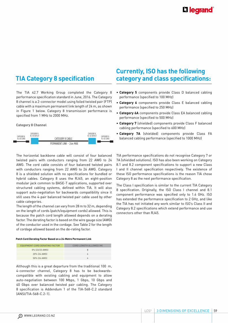
The TIA 42.7 Working Group completed the Category 8 performance specification standard in June, 2016. The Category 8 channel is a 2-connector model using foiled twisted pair (FTP) cable with a maximum permanent link length of 24 m, as shown in Figure 1 below. Category 8 transmission performance is specified from 1 MHz to 2000 MHz.
The horizontal backbone cable will consist of four balanced twisted pairs with conductors ranging from 22 AWG to 24 AWG. The cord cable consists of four balanced twisted pairs with conductors ranging from 22 AWG to 26 AWG. Category 8 is a shielded solution with no specifications for bundled or hybrid cables. Category 8 uses the RJ45, an eight-position modular jack common to BASE-T applications, supported over structured cabling systems, defined within TIA. It will also support auto-negotiation for backwards compatibility since it still uses the 4-pair balanced twisted pair cable used by other cable categories.The length of the channel can vary from 28 m to 32 m, depending on the length of cords (patch/equipment cords) allowed. This is because the patch cord length allowed depends on a derating factor. The derating factor is based on the wire gauge size (AWG) of the conductor used in the cordage. See Table 2 for the length of cordage allowed based on the de-rating factor.
Although this is a great departure from the traditional 100 m, 4-connector channel, Category 8 has to be backwards-compatible with existing cabling and equipment to allow auto-negotiation between 100 Mbps, 1 Gbps, 10 Gbps and 40 Gbps over balanced twisted pair cabling. The Category 8 specification is Addendum 1 of the TIA-568-C.2 standard (ANSI/TIA-568-C.2-1).
• Category 5 components provide Class D balanced cabling performance (specified to 100 MHz)
• Category 6 components provide Class E balanced cabling performance (specified to 250 MHz)
• Category 6A components provide Class EA balanced cabling performance (specified to 500 MHz)
• Category 7 (shielded) components provide Class F balanced cabling performance (specified to 600 MHz)
• Category 7A (shielded) components provide Class FA balanced cabling performance (specified to 1000 MHz)
TIA performance specifications do not recognise Category 7 or 7A (shielded solutions). ISO has also been working on Category 8.1 and 8.2 component specifications to support a new Class I and II channel specification respectively. The existence of these ISO performance specifications is the reason TIA chose Category 8 as the next performance specification.
The Class I specification is similar to the current TIA Category 8 specification. Originally, the ISO Class I channel and 8.1 component performance was specified only to 1.6 GHz. ISO has extended the performance specification to 2 GHz, and like the TIA has not initiated any work similar to ISO’s Class II and Category 8.2 specifications which extend performance and use connectors other than RJ45.
Currently, ISO has the following category and class specifications:TIA Category 8 specification
Category 8 Channel
Patch Cord Derating Factor Based on a 24-Metre Permanent Link
EQUIPMENT CORD DERATING FACTOR CORD LENGTH ALLOWED (M)
0% (22/23 AWG) 8
20% (24 AWG) 6
50% (26 AWG) 4
CATEGORY 8 CABLEPERMANENT LINK – 24m MAX
CATEGORY 8 RJ-45 CORD
CATEGORY 8 RJ-45 CORD
CATEGORY 8 RJ-45 OUTLET
CATEGORY 8 RJ-45 OUTLET

60
ISO is the International Organization for Standardization. It creates standards for structured cabling similar to TIA, with participation from international organisations; the US also has a participating delegation. The ISO/IEC 11801 standard is similar to the ANSI/TIA-568 standard.
Both organisations are trying to harmonise the standards but there are some differences. For example, ISO specifies the channel performance specification as a “Class” and component performance specifications as a “Category”. TIA has traditionally used “Category” to refer to the component, link and channel performance specifications.
ISO recognises several connector types for Category 8. These interfaces are shown in Table 3 below. Category 8.1/Class I uses an RJ45 interface. This is the same interface used in all TIA category specifications (TIA-568-C.2 standard), including the Category 8 specification. ISO recognizes three interfaces for Category 8.2/Class II; the TERA, GG45, and ARJ45. These are also recognised Category 7A interfaces in ISO. It remains uncertain whether TIA will adopt any of these connector interfaces if they create a Class II specification similar to ISO in the future.
Development of a Category 8 performance standard was driven by the need to support the next generation of NGBASE-T. The need for the next generation BASE-T standard was substantiated by a need to support Ethernet beyond 10GbE for server-to-switch connections. The existing 40 GbE over copper standard (ratified in 2010), 40GBASE-CR4, defines 40 Gbs over twinax cable for up to 7 m. This is sufficient for use within a rack or a neighbouring rack but not sufficient for supporting other architectures within a data center. Therefore, the initial application driving the development of NGBASE-T and Category 8 was support for server-to-switch connections within a row, such as end-of-row or middle-of-row architectures.
Category 8 will allow support of 40 Gbps over balanced twisted pair cable for 28 to 32 m depending on the patch cord wire gauge (AWG) used. This distance works well for use within racks, neighbouring racks, and end-of-row racks. Switch fabrics, such as leaf and spine, are growing in popularity in the data center and may also provide an application for Category 8. Category 8 will use an RJ45 interface, which is backwards-compatible with previous TIA category standards and will support auto- negotiation, making transitions to faster data applications easy.
A document has also been produced in TIA that identifies opportunities for high-performance structured cabling (i.e. Category 8). The TIA TR-42.7 subcommittee approved a new Technical Service Bulletin, TIA TSB-5019, “High Performance Structured Cabling Use Cases for Data Centers and Other Premises” published at the April 2015 plenary meeting. This document is intended to provide details for deploying future Category 8 structured cabling in data centers and other premises to support 25GBASE-T and 40GBASE-T applications. The document identifies, analyses and recommends architectures such as switch fabric, end-of-row, middle-of-row and top-of-rack for high-performance structured cabling using next generation BASE-T standards with data rates above 10GBASE-T such as 25GBASE-T and 40GBASE-T. These examples can be used in data center or premise designs such as test labs or equipment rooms requiring high bandwidth solutions.
What is the applicationISO/IEC Category 8 specification
Connection Interfaces for Category 8 in ISO Standards
CAT. 8 - Understanding the new performance category for balanced twisted pair cablec
PMD/INTERFACE SUPPORTED MEDIA TYPE DWG DESCRIPTION
Category 8.1/Class I TIA 568-C.2ISO/IEC 11801 RJ45
Category 8.2/Class II
IEC 61076-3-104(C7A Interface) TERA1
IEC 60603-7-71(C7A Interface) GG452
IEC 61076-3-110(C7A Interface) ARJ453
Notes: 1. TERA® is a registered trademark of The Siemon Company. 2. GG45® is a registered trademark of Nexans (France). 3. ARJ45® is a registered trademark of Bel Fuse Ltd (Hong Kong).
Next Gen BASE-T ideal for server-to-switch connections within the row
Distance covered by NGBASE-T Within the rack Neighbouring racks, stranded ports End of row
Distance covered by CR4 Within the rack Neighbouring racks
Within the rack Neighbouring racks, stranded ports End of row
Within the rack Neighbouring racks

613 DIMENSIONS OF EXCELLENCEWWW.LEGRAND.CO.NZ
LCS3
One of the biggest challenges has been defining the measurement technology required to assess and verify Category 8 component, link and channel performance. The frequency range has drastically increased from 500 MHz for Cat. 6A to 2000 MHz for Cat. 8. There are several task groups working on this.
Addendum 1 to the ANSI/TIA-1183: Measurement Methods and Test Fixtures for Balun Less Measurements of Balanced Components and Systems standard was completed in January 2016. This standard is intended to be used as an independent testing reference and describes methods and fixtures that support laboratory measurement of all differential mode, mixed mode, and common mode transmission parameters up to 1 GHz. Category 8 requires the frequency range to be extended to 2 GHz.
ANSI/TIA-1152-A, the requirements for field-testing balanced twisted pair cabling, including Category 8 performance, was approved for publication at the October plenary meeting.This standard provides requirements for field test instruments, as well as measurement methods for comparing field instrument measurements against measurements obtained using laboratory equipment. The challenge was that the frequency range to be tested had to be increased from 500 MHz (Cat. 6A) to 2000 MHz for Cat. 8.The table lists the field tester accuracy levels. TIA published the Category 8 standard in July 2016 and ISO should be published in the first quarter of 2017 IEC 61935-1.
Will Category 8 be widely adopted? That is the question being asked by many. A twisted-pair Ethernet (BASE-T) solution has advantages such as being one of the most widely adopted structured cabling technologies, low cost, using a common connector interface and auto-negotiation capabilities. The Category 8 standard does specify the RJ45 interface, making it compatible with all other TIA balanced twisted pair cabling standards.
The Category 8 channel length has been reduced from the historical 100-metre channel length and is a shielded solution, with the channel being limited to 2 connectors. Both the 30-metre channel length (can vary from 28-32 m depending on the cords) and 2-connector channel limitations must be included in designs intended to support future BASE-T applications.
How widely will Category 8 be adopted? Will fibre be less expensive? Time will tell, however, you should keep an eye on the active equipment manufacturers because they have a huge influence on what gets adopted.
TIA published the Category 8 standard in July 2016 and ISO should be published in the first quarter of 2018.
What are the challenges? Summary and conclusions
Field Tester Accuracy Levels
ISO by IEC (and IEC 61935-1)
CABLING STANDARD FREQUENCY RANGE (MHz) ACCURACY LEVEL
CAT 5e 100 Level II
CAT 6 250 Level III
CAT 6A 500 Level IIIe
CAT 8 2000 Level 2G
CABLING STANDARD FREQUENCY RANGE (MHz) ACCURACY LEVEL
CLASS F 600 Level IV
CLASS FA 1000 Level V (draft)
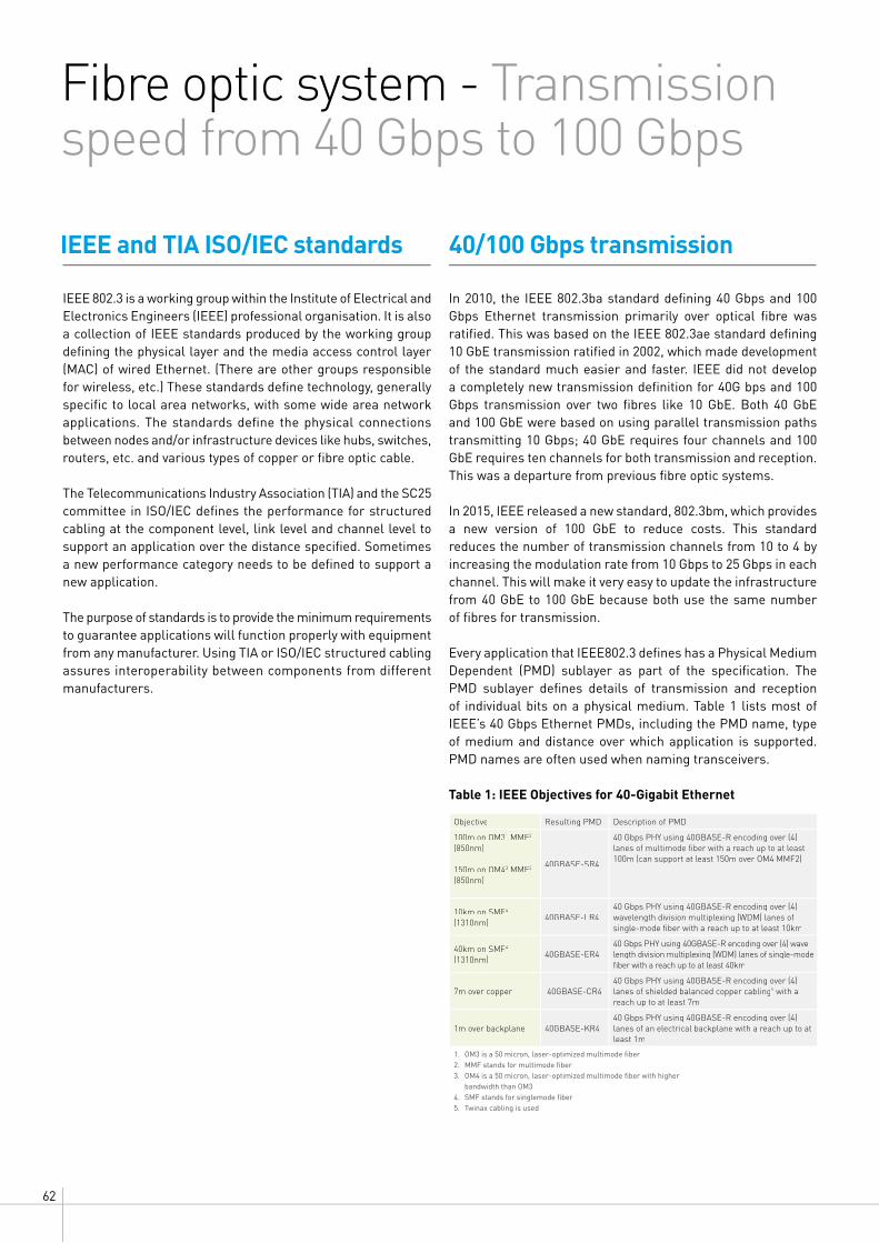
62
Fibre optic system - Transmission speed from 40 Gbps to 100 Gbps
IEEE 802.3 is a working group within the Institute of Electrical and Electronics Engineers (IEEE) professional organisation. It is also a collection of IEEE standards produced by the working group defining the physical layer and the media access control layer (MAC) of wired Ethernet. (There are other groups responsible for wireless, etc.) These standards define technology, generally specific to local area networks, with some wide area network applications. The standards define the physical connections between nodes and/or infrastructure devices like hubs, switches, routers, etc. and various types of copper or fibre optic cable.
The Telecommunications Industry Association (TIA) and the SC25 committee in ISO/IEC defines the performance for structured cabling at the component level, link level and channel level to support an application over the distance specified. Sometimes a new performance category needs to be defined to support a new application.
The purpose of standards is to provide the minimum requirements to guarantee applications will function properly with equipment from any manufacturer. Using TIA or ISO/IEC structured cabling assures interoperability between components from different manufacturers.
40/100 Gbps transmissionIEEE and TIA ISO/IEC standards
In 2010, the IEEE 802.3ba standard defining 40 Gbps and 100 Gbps Ethernet transmission primarily over optical fibre was ratified. This was based on the IEEE 802.3ae standard defining 10 GbE transmission ratified in 2002, which made development of the standard much easier and faster. IEEE did not develop a completely new transmission definition for 40G bps and 100 Gbps transmission over two fibres like 10 GbE. Both 40 GbE and 100 GbE were based on using parallel transmission paths transmitting 10 Gbps; 40 GbE requires four channels and 100 GbE requires ten channels for both transmission and reception. This was a departure from previous fibre optic systems.
In 2015, IEEE released a new standard, 802.3bm, which provides a new version of 100 GbE to reduce costs. This standard reduces the number of transmission channels from 10 to 4 by increasing the modulation rate from 10 Gbps to 25 Gbps in each channel. This will make it very easy to update the infrastructure from 40 GbE to 100 GbE because both use the same number of fibres for transmission.
Every application that IEEE802.3 defines has a Physical Medium Dependent (PMD) sublayer as part of the specification. The PMD sublayer defines details of transmission and reception of individual bits on a physical medium. Table 1 lists most of IEEE’s 40 Gbps Ethernet PMDs, including the PMD name, type of medium and distance over which application is supported. PMD names are often used when naming transceivers.
Table 1: IEEE Objectives for 40-Gigabit Ethernet
IEEE AND TIA STANDARDSIEEE 802.3 is a working group within the Institute of Electrical and Electronics Engineers (IEEE) professional organization. It is also a collection of IEEE standards produced by the working group defining the physical layer and the media access control layer (MAC) of wired Ethernet. (There are other groups responsible for wireless, etc.) These standards define technology, generally specific to local area networks, with some wide area network applications. The standards define the physical connections between nodes and/or infrastructure devices like hubs, switches, routers, etc. and various types of copper or fiber cable.
The Telecommunications Industry Association (TIA) defines the performance for structured cabling at the component level, link level and channel level to support an application over the distance specified. Sometimes a new category of performance must be defined to support a new application.
The purpose of standards is to provide the minimum requirements to guarantee applications will function properly with equipment from any manufacturer. Using TIA structured cabling assures interoperability between components from different manufacturers.
40/100 Gbps TRANSMISSION In 2010, the IEEE 802.3ba standard defining 40 Gbps and 100 Gbps Ethernet transmission primarily over optical fiber, was ratified. This was based on the IEEE 802.3ae standard defining 10 GbE transmission ratified in 2002, which made development of the standard much easier and faster. IEEE did not develop a completely new transmission definition for 40Gbps and 100 Gbps transmission over two fibers like 10 GbE. Both 40 GbE and 100 GbE were based on using parallel transmission paths transmitting 10 Gbps; 40 GbE requires four lanes and 100 GbE requires ten lanes for both transmitting and receiving. This was a departure from previous fiber systems.
In 2015, IEEE released a new standard, 802.3bm, which provides a new version of 100 GbE to reduce cost. This standard reduces the number of transmission lanes from 10 to 4 by increasing the modulation rate from 10 Gbps to 25 Gbps in each lane. This will make it very easy to update the infrastructure from 40 GbE to 100 GbE because both use the same number of fibers for transmission.
Every application that IEEE802.3 defines has a Physical Medium Dependent (PMD) sublayer as part of the specification. The PMD sublayer defines details of transmission and reception of individual bits on a physical medium. Table 1 lists most of IEEE’s 40 Gbps Ethernet PMDs including the PMD name, type of media and distance application is supported. PMD names are often used when naming transceivers.
Table 1: IEEE Objectives for 40 Gigabit Ethernet
Objective Resulting PMD Description of PMDResulting PMD Description of PMD
100m on OM31 MMF2
(850nm)
150m on OM43 MMF2
(850nm)
40GBASE-SR4
40 Gbps PHY using 40GBASE-R encoding over (4) lanes of multimode fiber with a reach up to at least 100m (can support at least 150m over OM4 MMF2)
10km on SMF4
(1310nm)40GBASE-LR4
40 Gbps PHY using 40GBASE-R encoding over (4) wavelength division multiplexing (WDM) lanes of single-mode fiber with a reach up to at least 10km
40km on SMF4
(1310nm)40GBASE-ER4
40 Gbps PHY using 40GBASE-R encoding over (4) wave-length division multiplexing (WDM) lanes of single-mode fiber with a reach up to at least 40km
7m over copper 40GBASE-CR47m over copper 40GBASE-CR47m over copper 40GBASE-CR440 Gbps PHY using 40GBASE-R encoding over (4) lanes of shielded balanced copper cabling5 with a reach up to at least 7m
1m over backplane 40GBASE-KR41m over backplane 40GBASE-KR41m over backplane 40GBASE-KR440 Gbps PHY using 40GBASE-R encoding over (4) lanes of an electrical backplane with a reach up to at least 1m
1. OM3 is a 50 micron, laser-optimized multimode fiber2. MMF stands for multimode fiber3. OM4 is a 50 micron, laser-optimized multimode fiber with higher bandwidth than OM34. SMF stands for singlemode fiber5. Twinax cabling is used
The initial goals were to support 40GbE for at least 100 meters over multimode fiber, up to at least 10 kilometers over single mode and up to 7 meters over shielded balanced copper (Twinax). With the release of OM4 (a 50 micron, laser-optimized multimode fiber (LOMF) with higher bandwidth than OM3) the distance can be extended to 150 meters. Another PMD was added in 2015 to support 40 GbE over single mode up to at least 40 kilometers. There is also a PMD defined for supporting 40 GbE at least 1 meter over an electrical backplane.
3

633 DIMENSIONS OF EXCELLENCEWWW.LEGRAND.CO.NZ
LCS3
The initial goals were to support 40GbE for at least 100 m over multimode fibre, up to at least 10 km over singlemode and up to 7 m over shielded balanced copper (Twinax). With the release of OM4 (a 50-micron laser-optimised multimode fibre (LOMF) with higher bandwidth than OM3) the distance can be extended to 150 m. Another PMD was added in 2015 to support 40 GbE over singlemode up to at least 40 km. There is also a PMD defined for supporting 40 GbE for at least 1 m over an electrical backplane.
Table 2 lists the objectives for supporting 100 GbE over specific media.
Table 2: IEEE Objectives for 100 Gigabit Ethernet
The objectives for both 40 and 100 GbE are the same; supporting the application over multimode fibre for at least 100 m, over singlemode fibre for at least 10 km and a longer option of 40 km, and over balanced copper cabling (Twinax) for up to at least 7 m. One thing to keep in mind is that 100GBASE-SR4 is supported for at least 100 m over multimode fibre when using OM4 but only 70 m over OM3.
The PMDs are summarised in table 3 for 40 GbE and table 4 for 100 GbE. The tables summarise the signalling, media and distance for both 40-Gigabit Ethernet and 100-Gigabit Ethernet.
Table 3: Signalling, Medium and Distance for 40-Gigabit Ethernet PMDs
Table 2 lists the objectives for supporting 100 GbE over specific media.
Table 2: IEEE Objectives for 100 Gigabit Ethernet
1. MMF stands for multimode fiber2. SMF stands for single-mode fiber3. Twinax cabling is used
The objectives for both 40 and 100 GbE are the same; support the application over multimode fiber at least 100 meters, over single mode fiber at least 10 kilometers and a longer reach 40 kilometers, and over balanced copper cabling (Twinax) up to at least 7 meters. One thing to keep in mind is that 100GBASE-SR4 is supported at least 100 meters over multimode fiber when using OM4 but only 70 meters over OM3.
The PMDs are summarized in table 3 for 40 GbE and table 4 for 100 GbE. The tables summarize the signaling, media and distance for both 40 Gigabit Ethernet and 100 Gigabit Ethernet.
Table 3: Signaling, Media and Distance for 40 Gigabit Ethernet PMDs
40 Gigabit Ethernet
PMD Name 40GBASE-SR4 40GBASE-LR4 40GBASE-ER4 40GBASE-CR4PMD Name 40GBASE-SR4 40GBASE-LR4 40GBASE-ER4 40GBASE-CR4PMD Name 40GBASE-SR4 40GBASE-LR4 40GBASE-ER4 40GBASE-CR4PMD Name 40GBASE-SR4 40GBASE-LR4 40GBASE-ER4 40GBASE-CR4PMD Name 40GBASE-SR4 40GBASE-LR4 40GBASE-ER4 40GBASE-CR4PMD Name 40GBASE-SR4 40GBASE-LR4 40GBASE-ER4 40GBASE-CR4
Signaling 4 x 10 Gbps 4 x 10 Gbps 4 x 10 Gbps 4 x 10 GbpsSignaling 4 x 10 Gbps 4 x 10 Gbps 4 x 10 Gbps 4 x 10 GbpsSignaling 4 x 10 Gbps 4 x 10 Gbps 4 x 10 Gbps 4 x 10 GbpsSignaling 4 x 10 Gbps 4 x 10 Gbps 4 x 10 Gbps 4 x 10 GbpsSignaling 4 x 10 Gbps 4 x 10 Gbps 4 x 10 Gbps 4 x 10 GbpsSignaling 4 x 10 Gbps 4 x 10 Gbps 4 x 10 Gbps 4 x 10 Gbps
Media Parallel MMF Duplex SMF Duplex SMF TwinaxMedia Parallel MMF Duplex SMF Duplex SMF TwinaxMedia Parallel MMF Duplex SMF Duplex SMF TwinaxMedia Parallel MMF Duplex SMF Duplex SMF TwinaxMedia Parallel MMF Duplex SMF Duplex SMF TwinaxMedia Parallel MMF Duplex SMF Duplex SMF Twinax
Distance0.5 – 100m OM3 /150m OM4
10km SMF40km SMF 7m Twinax40km SMF 7m Twinax
Table 4: Signaling, Media and Distance for 100 Gigabit Ethernet PMDs
Some key takeaways are that both 40 GbE and 100 GbE require more than two fibers for transmission over multimode fiber. 40 GbE requires four transmit and four receive multimode fibers, for a total of eight fibers per channel.
4
Table 4: Signalling, Media and Distance for 100-Gigabit Ethernet PMDs
Table 2 lists the objectives for supporting 100 GbE over specific media.
Table 2: IEEE Objectives for 100 Gigabit Ethernet
1. MMF stands for multimode fiber2. SMF stands for single-mode fiber3. Twinax cabling is used
The objectives for both 40 and 100 GbE are the same; support the application over multimode fiber at least 100 meters, over single mode fiber at least 10 kilometers and a longer reach 40 kilometers, and over balanced copper cabling (Twinax) up to at least 7 meters. One thing to keep in mind is that 100GBASE-SR4 is supported at least 100 meters over multimode fiber when using OM4 but only 70 meters over OM3.
The PMDs are summarized in table 3 for 40 GbE and table 4 for 100 GbE. The tables summarize the signaling, media and distance for both 40 Gigabit Ethernet and 100 Gigabit Ethernet.
Table 3: Signaling, Media and Distance for 40 Gigabit Ethernet PMDs
Table 4: Signaling, Media and Distance for 100 Gigabit Ethernet PMDs
100 Gigabit Ethernet
PMD 100GBASE-SR4 100GBASE-SR10 100GBASE-LR4 100GBASE-ER4 100GBASE-CR10100GBASE-ER4 100GBASE-CR10
Signaling 4 x 25 Gbps 10 x 10 Gbps 4 x 25 Gbps 4 x 25 Gbps 10 x 10 Gbps4 x 25 Gbps 10 x 10 Gbps 4 x 25 Gbps 4 x 25 Gbps 10 x 10 Gbps4 x 25 Gbps 10 x 10 Gbps 4 x 25 Gbps 4 x 25 Gbps 10 x 10 Gbps4 x 25 Gbps 10 x 10 Gbps 4 x 25 Gbps 4 x 25 Gbps 10 x 10 Gbps4 x 25 Gbps 10 x 10 Gbps 4 x 25 Gbps 4 x 25 Gbps 10 x 10 Gbps
Media Parallel MMF Parallel MMF Duplex SMF Duplex SMF TwinaxParallel MMF Duplex SMF Duplex SMF TwinaxParallel MMF Duplex SMF Duplex SMF TwinaxParallel MMF Duplex SMF Duplex SMF Twinax
Distance100m OM4/ 70m OM3
100m OM3 /150m OM4
10km SMF40km SMF 7m Twinax40km SMF 7m Twinax
Some key takeaways are that both 40 GbE and 100 GbE require more than two fibers for transmission over multimode fiber. 40 GbE requires four transmit and four receive multimode fibers, for a total of eight fibers per channel.
4
Some key takeaways are that both 40 GbE and 100 GbE require more than two fibres for transmission over multimode fibre. 40 GbE requires four transmit and four receive multimode fibres, making a total of eight fibres per channel.
The newer 100 GbE PMD, 100GBASE-SR4, uses the same cable plant (eight fibres) as 40 GbE, providing a seamless migration path. The singlemode options for 40 GbE and 100 GbE also require multichannel transmission. 40-Gigabit Ethernet over singlemode uses four transmit channels and four receive channels, each transmitting at 10 Gbps. 100-Gigabit Ethernet over singlemode uses four transmit and four receive channels, each transmitting at 25 Gbps. IEEE 802.3ba, the 40 Gbps and 100 Gbps Ethernet transmission standard, specifies signalling over singlemode fibre using wavelength division multiplexing (WDM) transmission. This means that for 40 GbE and 100 GbE over singlemode fibre, each of the four channels is transmitted at a different wavelength.
40GBASE-LR4 transmission is defined by a center wavelength and wavelength range for each channel. The center wavelengths used for the four channel are members of the CWDM (Conventional/Course Wavelength Division Multiplexing) grid defined in the ITU-T G.694.2 standard. This standard defines a channel spacing grid using wavelengths from 1271 to 1611 nm, with channel spacing of 20 nm. Table 5 shows the center wavelength and wavelength range for each 40GBASE-LR4 transmission channel.
Table 2 lists the objectives for supporting 100 GbE over specific media.
Table 2: IEEE Objectives for 100 Gigabit Ethernet
Objective Resulting PMD Description of PMDResulting PMD Description of PMD
100m on OM3 MMF1
(850nm)
150m on OM4 MMF1
(850nm)
100GBASE-SR10
100 Gbps PHY using 100GBASE-R encoding over (10) lanes of multimode fiber with a reach up to at least 100m (can support at least 150m over OM4 MMF1)
70m on OM3 MMF1
(850nm)
100m on OM4 MMF1
(850nm)
100GBASE-SR4
100 Gbps PHY using 25 Gbps data rate over (4) lanes of multimode fiber with a reach up to at least 100m (can support at least 100m over OM4 MMF or 70m over OM3 MMF)
10km on SMF2
(1310nm)100GBASE-LR4
100 Gbps PHY using 100GBASE-R encoding over (4) wavelength division multiplexing (WDM) lanes on single-mode fiber with a reach up to at least 10km
40km on SMF2
(1310nm)100GBASE-ER4
100 Gbps PHY using 100GBASE-R encoding over (4) wavelength division multiplexing (WDM) lanes on single-mode fiber with a reach up to at least 40km
7m over copper 100GBASE-CR10100 Gbps PHY using 100GBASE-R encoding over (10) lanes of shielded balanced copper cabling3 with a reach up to at least 7m
1. MMF stands for multimode fiber2. SMF stands for single-mode fiber3. Twinax cabling is used
The objectives for both 40 and 100 GbE are the same; support the application over multimode fiber at least 100 meters, over single mode fiber at least 10 kilometers and a longer reach 40 kilometers, and over balanced copper cabling (Twinax) up to at least 7 meters. One thing to keep in mind is that 100GBASE-SR4 is supported at least 100 meters over multimode fiber when using OM4 but only 70 meters over OM3.
The PMDs are summarized in table 3 for 40 GbE and table 4 for 100 GbE. The tables summarize the signaling, media and distance for both 40 Gigabit Ethernet and 100 Gigabit Ethernet.
Table 3: Signaling, Media and Distance for 40 Gigabit Ethernet PMDs
Table 4: Signaling, Media and Distance for 100 Gigabit Ethernet PMDs
Some key takeaways are that both 40 GbE and 100 GbE require more than two fibers for transmission over multimode fiber. 40 GbE requires four transmit and four receive multimode fibers, for a total of eight fibers per channel.
4

64
Fibre optic system - transmission speed from 40 Gbps to 100 Gbps
Based on the aforementioned standards, all 40/100-Gigabit Ethernet options over multimode fibre use parallel transmission, requiring more than two fibres per channel. Fibre connectivity must be able to terminate more than two fibres. This is a departure from connectivity used in systems supporting up to 10-Gigabit Ethernet, which only requires a total of two fibres per channel. The most common connector for transmission over two fibres is the LC. This is the only connector recommended for new installations requiring two fibres for transmission in the TIA data center standard, ANSI/TIA-942 and ISO/IEC 11801 3rd Edition and especially ISO/IEC 11801-5 for data centers. This connector is used for 10 GbE and below over multimode fibre, as well as the 40/100 GbE singlemode options reviewed previously.
With the need to support multiple transmission channels, the Media Dependent Interface (MDI) identified by the IEEE 802.3ba standard for 40 GbE and 100 GbE transmission (when not using WDM) is the MPO-style connector. The MPO connector is the connector recommended by the ANSI/TIA-942 data center standard ISO/IEC 11801 3rd Edition and especially ISO/IEC 11801-5 for data centers for applications requiring parallel fibre transmission. The terms “MPO” and “MTP®” are used interchangeably for this style of connector. MPO is the generic name for this Multi-Fibre Push On connector style. MTP is an MPO-style connector and a registered trademark of US Conec, Ltd. It is considered in the industry to be a better performing connector with lower insertion loss.
MPO Connector
MPO female plug connector �at interface
Fiber cable
Key
Alignment hole
Keyway
Male MDI as a PMD receptacle for mating with a female MPO plug connector.
Alignment pin
40/100-Gigabit Ethernet connectivity and cable
100GBASE-LR4 and 100GBASE-ER4 also define a wavelength range for each channel. The wavelength range is the same for both 100GBASE PMDs as shown in table 5. These ranges are based on center frequencies that are part of the frequency grid defined in the ITU-T G.694.1 standard. This standard defines a set of frequencies used to designate allowed central frequencies to support dense wavelength division multiplexing (DWDM) applications. This standard supports a variety of channel spacing ranging from 12.5 GHz to 100 GHz and wider, beginning at 193.1 THz. 100GBASE-LR4 and 100GBASE-ER4 channels use center frequencies from 229 THz to 231.4 THz and are spaced at 800 GHz.
Table 5 shows the center frequency, correlating center wavelength and wavelength range for each 100GBASE-LR4 and 100GBASE-ER4 channel.
Table 5: Wavelength-Division-Multiplexed Lane Assignments
The newer 100 GbE PMD, 100GBASE-SR4, uses the same cable plant (eight fibers) that 40 GbE uses providing a seamless migration path. The single-mode options for 40 GbE and 100 GbE require multiple-lane transmission as well. 40 Gigabit Ethernet over single-mode uses four transmit lanes and four receive lanes, each transmitting at 10 Gbps. 100 Gigabit Ethernet over single-mode uses four transmit and four receive lanes, each transmitting at 25 Gbps. IEEE 802.3ba, the 40 Gbps and 100 Gbps Ethernet transmission standard, specifies signaling over single-mode fiber using wavelength division multiplexing (WDM) transmission. This means that for 40 GbE and 100 GbE over single-mode fiber, each of the four lanes is transmitted at a different wavelength.
40GBASE-LR4 transmission is defined by a center wavelength and wavelength range for each lane. The center wavelengths used for the four lanes are members of the CWDM (Conventional/Course Wavelength Division Multiplexing) grid defined in the ITU-T G.694.2 standard. This standard defines a channel spacing grid using wavelengths from 1271 to 1611 nm, with a channel spacing of 20nm. Table 5 shows the center wavelength and wavelength range for each 40GBASE-LR4 transmission lane.
100GBASE-LR4 and 100GBASE-ER4 define a wavelength range for each lane also. The wavelength range is the same for both 100GBASE PMDs as shown in table 5. These ranges are based on center frequencies that are part of the frequency grid defined in the ITU-T G.694.1 standard. This standard defines a set of frequencies used to designate allowed central frequencies to support dense wavelength division multiplexing (DWDM) applications This standard supports a variety of channel spacing ranging from 12.5 GHz to 100 GHz and wider, beginning at 193.1 THz. 100GBASE-LR4 and 100GBASE-ER4 lanes use center frequencies from 229 THz to 231.4 THz and are spaced at 800 GHz.
Table 5 shows the center frequency, correlating center wavelength and wavelength range for each 100GBASE-LR4 and 100GBASE-ER4 lane.
Table 5: Wavelength-Division-Multiplexed Lane Assignments
40GBASE-LR4 100GBASE-LR4 and 100GBASE-ER4
LaneCenter Wavelength
Wavelength Range
Center Frequency
Center Wavelength
Wavelength Range
L0 1271 nm1264.5 to 1277.5 nm
231.4 THz 1295.56 nm231.4 THz 1295.56 nm1294.53 to 1296.59 nm
L1 1291 nm1284.5 to 1297.5 nm
230.6 THz 1300.05 nm230.6 THz 1300.05 nm1299.02 to 1301.09 nm
L2 1311 nm1304.5 to 1317.5 nm
229.8 THz 1304.58 nm229.8 THz 1304.58 nm 1303.54 to 1305.63 nm
L3 1331 nm1324.5 to 1337.5 nm
229 THz 1309.14 nm229 THz 1309.14 nm 1308.09 to 1310.19 nm
Since the different wavelengths do not interfere with each other when transmitted on a single fiber, all four can be transmitted over one fiber. If the four lanes of the signal were transmitted at the same wavelength then four fibers are needed to separate the lanes as in parallel transmission over multimode. The four receive lanes also use WDM transmission so 40 GbE and 100 GbE channels over single-mode only require a total of two fibers; one transmit fiber and one receive fiber. These cables typically use LC connectors. There is no requirement to associate a particular electrical lane with a particular optical lane since the transceiver is capable of receiving lanes in any order.
Both 40 GbE and 100 GbE have a copper option for up to 7 meters using Twinaxial cable. 802.3ba does not define a twisted-pair option.
40/100 GIGABIT ETHERNET CONNECTIVITY AND CABLEBased on the standards just reviewed, all 40/100 Gigabit Ethernet options over multimode fiber use parallel transmission, requiring more than two fibers per channel. Fiber connectivity must be able to terminate more than two fibers. This is a departure from connectivity used in systems supporting up to 10Gigabit Ethernet, which only requires a total of two fibers per channel. The most common connector for transmission over two fibers is the LC. This is the only connector recommended for new installations requiring two fibers for transmission in the TIA data center standard, ANSI/TIA-942. This connector is used for 10 GbE and below over multimode fiber, as well as the 40/100 GbE single-mode options reviewed previously.
With the need to support multiple transmission paths, the Media Dependent Interface (MDI) identified by the IEEE 802.3ba standard for 40 GbE and 100 GbE transmission (when not using WDM) is the MPO style connector. The MPO connector is the connector recommended by the ANSI/TIA-942 data center standard, for applications requiring parallel fiber transmission. The terms “MPO” and “MTP®” are used interchangeably for this style of connector. MPO is the generic name for this Multi-Fiber Push On connector style. MTP is an MPO-style connector and a registered trademark of US Conec, Ltd. It is considered in the industry to be a better performing connector with lower insertion loss.
5Notes: MTP® is a registered trademark of US Conec, Ltd.
Since the different wavelengths do not interfere with each other when transmitted on a single fibre, all four can be transmitted over one fibre. If all four signal channels are transmitted at the same wavelength then four fibres are needed to separate the channels as in parallel transmission over multimode. The four receive channels also use WDM transmission so 40 GbE and 100 GbE channels over singlemode only require a total of two fibres; one transmit fibre and one receive fibre. These cables typically use LC connectors. There is no requirement to associate a particular electrical channel with a particular optical channel since the transceiver is capable of receiving channels in any order.
Both 40 GbE and 100 GbE have a copper option for up to 7 m using Twinaxial cable. 802.3ba does not define a twisted pair option.
Notes: MTP® is a registered trademark of US Conec, Ltd.

653 DIMENSIONS OF EXCELLENCEWWW.LEGRAND.CO.NZ
LCS3
MPO connectors are typically terminated onto 12 fibres. MPOs may also be terminated onto 24 fibres. There is a keyway for maintaining polarity. (Polarity is covered in more depth later in this paper in the section entitled, “Fibre Considerations when Migrating to 40/100-Gigabit Ethernet”). The connector has precision alignment pins or holes to ensure all fibres align properly with the mating connector. The component type (i.e. cassette, adaptor panel, trunk cable) usually dictates whether there are pins or holes; pins are usually on fixed components like cassettes. If not properly cleaned, alignment pins can collect debris around the pins, resulting in the two components not mating correctly.
IEEE 802.3ba identifies specific positions on an MPO connector to use for transmission and reception. The four transmit and four receive fibre optic channels of 40GBASE-SR4 (40 GbE over multimode) must occupy the positions shown in the figure below.Looking at the end of the MPO, with the connector key on top, the transmit fibre optic channels occupy the four leftmost positions and the receive fibre optic channels occupy the four rightmost positions. There are eight active channels within twelve positions in total, with the four middle positions unused.
Option B and C use two 12-position MPO connectors. Option B, shown in the figure below, uses side-by-side interfaces. The 10 middle positions of the right-hand interface are used for reception and the 10 middle positions of the left-hand interface are used for transmission.
Options C is similar to option B, but uses the stacked layout depicted in the figure below. The ten middle positions of the top connector are used for reception and ten middle positions of the bottom connector are used for transmission.
Equipment manufacturers usually play a key role in driving the adoption of a particular MDI (Media Dependent Interface) option. For example, Option A, the single 24-position MPO has more connections in a smaller footprint, making it more complex and therefore more costly to manufacture. Option B, two 12-fibre side-by-side MPO connectors, requires twice the width of the other two options. Option C, two stacked 12-position MPO connectors, is single-width, but takes up more vertical space, where rack units could potentially be added
The 100GBASE-SR10 (100 GbE over multimode) requires a total of 20 fibres, 10 transmit and 10 receive. Position assignments are shown below. There are three options, the first being a single receptacle shown as Option A in figure below. Option A is recommended by IEEE. The two-receptacle options: Option B and Option C are alternatives.
Option A uses a 24-position MPO connector with the top middle 10 positions allocated for reception and the bottom 10 middle positions allocated for transmission, as shown in the figure below.
100G-BASE-SR10 Fibre Optic Channel Assignments Option A: Single connector (recommended)
40G-BASE-SR4 Fibre Optic Channel Assignments
100G-BASE-SR10 Fibre Optic Channel Assignments Option B: Side by side (alternative)
100G-BASE-SR10 Fibre Optic Channel Assignments Option B: Side by side (alternative)
Tx Tx Tx Tx Rx Rx Rx Rx

66
Fibre considerations when migrating to 40/100-Gigabit EthernetMultimode fibre systems have been the most cost-effective fibre solution to use in the data center because the transceivers are much less expensive than singlemode transceivers. Multimode transceivers use a vertical cavity surface emitting laser (VCSEL) light source, which is easy to manufacture and package. Multimode fibre systems have a shorter reach than singlemode systems, however most distances are less than 150 m; surveys have shown that more than 80% of data centers extend to 100 m or less. Although singlemode cable is less expensive, after factoring in the total system cost of multimode versus singlemode, multimode is still much less expensive.
Some common approaches used in data centers are summarised in Table 6 below. Each approach uses short-wavelength (850 nm) transmission over multimode fibre.
The fibre system should be designed around OM3 or OM4 MMF if there are plans to support applications beyond 10 Gbps. OM3 supports 10 GbE up to 300 m, but only supports 40 GbE up to 100 m. OM3 supports the 100GBASE-SR10 PMD up to 100 m
Table 6: Common Data Center Approaches Using Short Wavelength Transmission
Table 7: Maximum Channel Insertion Loss
but only supports 100GBASE-SR4 up to 70 m so that is another important consideration. OM4 supports 10 GbE up to 550 m, but only supports 40 GbE up to 150 meters. OM4 supports the 100GBASE-SR10 PMD up to 150 m but only supports 100GBASE-SR4 up to 100 m.
If planning to support 40 GbE and/or 100 GbE in the future, the channel cannot be designed for the maximum distances over which 10G can be supported. If the data center has distances exceeding 70 m it is a good idea to use OM4, since OM4 supports 10 GbE through 100 GbE for up to at least 100 m. Always design for the application that has the most stringent requirements (usually the fastest data rates) even if the application is a future installation.
In addition to selecting the type of fibre, OM3 or OM4, there are several other important considerations when selecting components for a fibre optic cabling system. These include channel insertion loss, polarity and alignment pins.
Channel Insertion Loss/Loss Budget
The channel insertion loss is made up of the insertion loss (IL) of the cable, specified as decibels per kilometer (dB/km), the insertion loss of all mated connector pairs and the insertion loss
of splices in that channel. As can be seen in the table below, as the data rate increases from 10 Gbps to 40/100 Gbps, the total channel insertion loss or loss budget decreases noticeably.
PMD Name Fibre Type Total Number of Fibres
Max Link Length (m)
Max Channel Insertion Loss (dBs)
10 GbE 10GBASE-SR OM3 2 300 2.6
40 GbE 40GBASE-SR4 OM3 8 100 1.9
40 GbE 40GBASE-SR4 OM4 8 150 1.5
100 GbE 100GBASE-SR4 OM3 8 70 1.9
100 GbE 100GBASE-SR4 OM4 8 100 1.9
100 GbE 100GBASE-SR10 OM3 20 100 1.9
100 GbE 100GBASE-SR10 OM4 20 150 1.5
10G 40G 100G (-SR10) 100G (-SR4)
Signalling 10Gb 10Gb x 4 10Gb x 10 25 Gb x 4
Laser Type VCSEL VCSEL Array VCSEL Array VCSEL Array
Fibre Type OM3/OM4 OM3/OM4 OM3/OM4 OM3/OM4
Connector 2 LCs 12-fibre MPO (2) 12-fibre MPOs or 24-fibre MPO
12-fibre MPO
Number of Fibres Needed
2 fibres 8 fibres 20 fibres 8 fibres
Maximum Distance OM3: 300 mOM4: 550 m
OM3: 100 mOM4: 150 m1
OM3: 100 mOM4: 150 m1
OM3: 70 mOM4: 100 m
1. 150 m over OM4 requires low-loss connectors. This is discussed in the channel insertion section.

673 DIMENSIONS OF EXCELLENCEWWW.LEGRAND.CO.NZ
LCS3
Fibre considerations when migrating to 40/100-Gigabit Ethernet
Understanding the impact of each component in the channel loss budget is extremely important when selecting cables and connectors. Often, the cable attenuation performance and bandwidth drive the design of the channel. The impact that a connector can have on the total channel budget can be significant.
The figure below shows the total loss budgets for a 100 m channel at different data rates common to current Ethernet applications. As data rates progress from 100 Mbps Ethernet-based systems to today’s 10 Gbps Ethernet-based systems, the fibre optic loss budgets have shrunk considerably from 11 dB to 2.6dB. 40/100 Gbps Ethernet systems have an even smaller budget of 1.9 dB when using OM3 or 1.5dB when using OM4.
Total Channel Insertion Loss by Application
If we look at a 3-connector-pair channel, the loss budget rises to 1.85 dB ((3.5db/km * 0.1km) + (0.5 * 3)), as shown in the figure below. This is more than 70% of the 10 Gbps budget and almost the entire 40/100 Gbps budget. This would exceed the loss budget using OM4 for 150 m, which is 1.5 dB because of the longer distance, proving the insertion loss of a connector is very important.
It is important to consider the trade-off. If the IL of one component can be reduced, there will be room for extra loss in another component. For example, if using OM4 at only 100 m instead of 150 m, the loss of the cable will be less because IL is directly related to distance (dB/km). This can make room for more mated connector pairs. However, all of the IL gain can easily be negated with inferior connector components.
If we look at two channel insertion loss budget examples for 2 and 3 mated pairs, including the cable loss for a 100 m link at 850 nm, the importance of connector loss is apparent.Using the standard loss for a multimode fibre cable (OM3/OM4, 850 nm) of 3 dB/km (ISO/IEC 11801 3rd Edition-Q2 2017) and an average of 0.50 dB loss per mated connector pair (TIA standards allow up to a maximum 0.75 dB loss and up to 4 connections), the calculated loss for a 100 m channel with 2 mated connector pairs is 1.35 dB ((3.5db/km * 0.1km) + (0.5 * 2)). Applied to the loss budgets, as shown in the figure below, this is not significant for 100 Mbps systems. However, the insertion loss takes up a little more than half of the 10G budget and almost three-quarters of the 40/100 Gbps budget.
Polarity
Don’t forget to plan for the correct polarity. Maintaining correct polarity guarantees an optical path from the transmit port of one device to the receive port of another device, known as the polarity flip. There are several different methods to maintain polarity, but the different methods may not be interoperable.There are three methods depicted in the TIA standards ISO/IEC 14763-2 “planning and installation”; methods A, B and C. There are other proprietary methods used by various manufacturers.
Each method requires a specific combination of components to maintain polarity. Assuming duplex signalling, using an MPO backbone cable, cassettes and patch cords, the following list shows the component options that are used in specific combinations for each of the polarity methods.
The options for components are:
• MPO-to-MPO backbone cables: Type A, B or C• MPO-to-LC cassettes: Method A or Method B• Patch cords: Type A-to-A or Type A-to-B
11.0 dB
100 Mbps 1 Gbps 10 Gbps 40/100 Gbps(OM3)
2.6 dB 1.9 dB3.0 dB
11.0 dB1.35 dB
insertion loss
100 Mbps 1 Gbps 10 Gbps 40/100 Gbps(OM3)
2.6 dB 1.9 dB3.0 dB
Channel Insertion Loss In a 100 M Channel with 2 Mated Connector Pairs
100 Mbps 1 Gbps 10 Gbps 40/100 Gbps(OM3)
1.85 dBinsertion loss
11.0 dB
2.6 dB 1.9 dB3.0 dB
Channel Insertion Loss In a 100 M Channel with 3 Mated Connector Pairs
A-to-A Patch Cord
A
B
A
B
B
A
B
AA-to-B Patch Cord
A-to-A and A-to-B Patch Cords

68
Fibre considerations when migrating to 40/100-Gigabit Ethernet
Alignment Pins
When mating connector plugs that use alignment pins, like the MPO connector, it is critical that one plug is pinned and the other plug is unpinned. Because all known transceivers that accept MPO plugs are pinned, they accept only unpinned plugs.
Polarity becomes more complicated when migrating to 40/100 GbE because parallel transmission replaces duplex transmission. Parallel fibre optic links integrate multiple transmitters in one transmitter module, multiple fibres in fibre array connectors and multiple receivers in one receiver module. Multiple transmitters and receivers may also be integrated together in a transceiver module.The three methods, A,B and C, are expanded in the ANSI/TIA-568 ISO/IEC 14763-2 standard to include links that use parallel signalling in one row (24-fibre MPO). Array connectors are keyed to maintain polarity. A keyed MPO connector is shown in the figure below.
The pinned connector is typically located inside the panel to help protect the pins from being damaged (i.e. the fixed connector is pinned and the connector that is frequently removed and handled is unpinned). For example, cassettes are typically pinned and trunk cables are typically unpinned.
Consult the manufacturer since there may be exceptions required for your design.If not properly cleaned, alignment pins can collect debris around the pins, resulting in the two components not mating correctly.
For example, with duplex signalling, a Method A polarity scheme uses a Method A cassette, Type A trunk cable and a type A-to-B patch cord on one end of the channel and a type A-to-A patch cord on the other end. The transmit to receive flip occurs in the patch cord at one end. Method B uses a Method B cassette and trunk cable and an A-to-B patch cord at each end because the flip occurs in the cassette and trunk cable. Method C uses a Method A cassette with a Type C trunk cable and A-to-B patch cords at each end. The flip occurs in the trunk cable only.
IEEE has a number of ongoing projects for both copper and fibre applications. A key fibre-application project underway is for 400 GbE. The goal is to provide physical layer specifications, supporting the following link distances:
At least 100 m over MMFAt least 500 m over SMFAt least 2 km over SMF At least 10 km over SMF
The first phase of 400 GbE over MMF uses 16 channels for transmission in both directions (total of 32 channels), each transmitting at 25 Gbps. To support this, TIA published a standard for 16- and 32-fibre MPO-style array connectors, ANSI/TIA-604-18 (FOCUS 18) at the end of 2015.
To provide a cost and performance migration path to 400 GbE, IEEE added support for two-channel 100 Gbps and four-channel 200 Gbps sometimes called NGOATH (Next Generation One and Two Hundred). Both of these are based on 50 Gbps channel rates. As a result, IEEE is also defining a single-channel 50 Gbps PHY with supported distances of at least 100 m over multimode fibre along with 2 km and 10 km options over singlemode fibre.
This two-channel 100 GbE will be supported over multimode fibre up to at least 100 m and up to at least 500 m over singlemode fibre. 200 GbE will be supported over multimode fibre at least 100 m, also. There will be several singlemode options including supporting a distance of at least 500 m using 4-channel parallel singlemode fibre (four parallel fibres), supporting a distance of at least 2 km over duplex singlemode fibre and supporting a distance of at least 10 km over duplex singlemode fibre.
The wideband MMF TIA standard was approved for publication in the middle of 2016. The standard specifies high bandwidth 50 µm core diameter/125 µm cladding diameter, laser-optimised optical fibre that is optimised to enhance performance for single wavelength or multi-wavelength transmission systems with wavelengths in the vicinity of 850 nm to 950 nm. The actual operating band is from 850 nm to 953 nm. The effective modal
What’s coming?
MPO Ferrule Alignment Pin Holes Key shown up
…………
Position 12 Position 1
MPO Plug Fibre Positions Looking at the Ferrule End with Key Up
MPO Connector With Pins Installed
AlignmentPins

693 DIMENSIONS OF EXCELLENCEWWW.LEGRAND.CO.NZ
LCS3
bandwidth (EMB) for this new fibre is specified at the lower and upper wavelengths: 4700 MHz•km at 850 nm and 2470 MHz•km at 953 nm. ISO/IEC has assigned the OM5 designation for this type of fibre.
This is a significant standard for multimode fibre because it makes wavelength division multiplexing (WDM) possible over multimode fibre. Since the fibre is optimised for short wavelengths, the wavelength division multiplexing used over multimode fibre is commonly called short wavelength division multiplexing (SWDM). Up until now, WDM has only been used with singlemode fibre. WDM is important because it is one of four ways to increase the data rate: WDM, parallel transmission with multiple fibres, increased modulation and using multi-level coding.
To show how this new standard can influence fibre optic plant for current and in-progress Ethernet standards refer to Table 8. The current 40 GbE (40GBASE-SR4) standard, using short wavelength over multimode fibre (MMF), uses a channel rate of 10 Gbps with eight fibres; four fibres for transmission and four fibres for reception. Using WBMMF that supports four wavelengths (in effect four channels) the four transmit fibres are reduced to one fibre, as are the receive fibres. The fibre optic cable plant is reduced from eight fibres to two. 100GbE is an even better example because the original standard released in 2010 (100GBASE-SR10) required a total of 20 fibres, 10 transmit and 10 receive, using a 10Gbps channel rate. A new 100GbE standard (100GBASE-SR4) was published in 2015 specifying a 25Gbps channel rate which allowed the fibre count to be reduced to a total of eight fibres; the same fibre count as 40GbE. This is an example of how increased modulation reduces the fibre count. Using SWDM with the new WBMMF will reduce the fibre optic plant to two fibres for 100 GbE using a 25 Gbps channel rate. Both 40 GbE and 100 GbE are reduced to duplex transmission.
As was mentioned, Phase I of the 400GbE (IEEE 802.3bs) standard will specify transmission over multimode using parallel transmission with a channel rate of 25 Gbps. This will require a total of 32 fibres. Employing SWDM over WBMMF reduces the fibre count to 8 fibres, 25% of the number of fibres required in Phase I.
There are also many developments within Fibre Channel, a high-speed network technology primarily used to connect computer data storage. 32G Fibre Channel (GFC) was published and transceivers have been trialled since the 3rd quarter of 2016. The target link distance is 100 m over OM4 and 70 m over OM3. 32 GFC still uses serial transmission with 2 fibres and will use the same external small form factor pluggable (SFP) transceiver modules with LC fibre optic connectors. This will be backwards-compatible with 8 GFC and 16 GFC. There is a new project looking at 128 GFC. Normally, Fibre Channel doubles in speed, 8 GFC, 16 GFC, 32 GFC, etc., but 128 GFC will be based on 32 GFC. 128 GFC will use 4 x 32 GFC.
A port will be able to auto-negotiate 128 GFC back to 32 GFC and 16 GFC without user intervention.
There are ongoing discussions to combine both 64 GFC and 256 GFC. Having a SWDM MMF option, based on Wide Band MMF TIA-492AAAE, is also being considered. Requirements will include backwards compatibility with 32 GFC.
Before selecting a product for your data center design, establish the fastest application your structured cabling will need to support. Multimode fibre systems are more common than singlemode systems for short distances because they are more cost-effective. Select at least OM3, however OM4 will provide longer-distance support or more connections over shorter distances. Some newer applications are supported up to 100 m only by OM4, so be aware of the application and distance requirements.
Wideband multimode fibre will have a huge influence on the fibre optic cable plant. As long as transceivers are available, two fibres can support up to 100 GbE using duplex transmission. If a transceiver can support 50 Gbps per channel using SWDM over wideband fibre, even the new 200 GbE could use duplex transmission (2 fibres in total). Wideband multimode fibre requires 25% of the total number of OM4 fibres to support applications traditionally using parallel transmission (multiple transmit and multiple receive fibres).
The type of connector is determined by the transmission; LC for duplex transmission and MPO/MTP® for parallel transmission. Channel insertion loss is the foundation for design, so consider high-performance, low-loss components.
You will also need to consider the polarity method to be used and then select the correct components to support that method. If using array connectors for parallel transmission, consider which components require pins and which do not. The best option is to work with the manufacturer to make sure the correct components are selected.
Don’t forget to put as much thought into designing your physical infrastructure as the structured cabling. The connection density in switches, servers and routers is increasing. This means more cable to manage and higher operating temperatures, making properly managed airflow extremely important. The correct infrastructure design is critical to extend the life of the network and protect your investment.
Conclusions

70
CPR – Construction Products RegulationThe aim of the CPR regulation is to guarantee the free circulation of products made in the European Union, adopting a harmonised technical language which can define the performance and essential features of all construction products.
Electrical cables are rarely the cause of a fire but when they are involved they may form a seriously hazardous component because of their large quantities and because they are found in all rooms of the building. With careful prevention and making state-of-the-art systems with safe and high-quality components in accordance with the CPR regulation, fire propagation, the lack of visibility in smoke-filled rooms and the diffusion of corrosive and toxic gases can be reduced or almost totally eliminated.
The CPR regulation (EU 305/2011) concerns all the products made to be permanently incorporated (installed/used) in buildings and other civil engineering works (e.g. homes, industrial and commercial buildings, offices, hospitals, schools, undergrounds, etc.). As part of the features considered important for the safety of constructions included in the CPR, the European Commission has decided to consider cables’ Reaction to Fire and Resistance to Fire, recognising the importance of their behaviour and role in fire. The release of harmful substances is one of the performances considered important for cables, although at present no minimum levels of performance have been established because when used normally the cables do not release harmful substances.All the cables installed permanently in constructions, to transport power or for telecommunications, of any voltage level and with copper or fibre optic conductors, must be classified on the basis of the classes of premises where they will be installed.
The cables are classified in 7 classes of Reaction to Fire: Aca, B1ca, B2ca, Cca, Dca, Eca and Fca identified by the subscript “ca” (cable) as a function of their decreasing performance. As well as this main classification, the European authorities have also regulated the use of the following additional parameters:
• a = acidity which defines the hazard of the fumes for people and the corrosiveness for things. Varies from a1 to a3
• s = opaqueness of the smoke. Varies from s1 to s3• d = dropping of incandescent particles which could propagate
fire. Varies from d0 to d2.
A more severe check (System 1+) is required for the classes from Aca to Cca. It lays down the initial check and continuous monitoring of the product and checks of the manufacturing control system, while for the classes from Dca to Eca the check only lays down the initial product check (System 3). Class F, however, is based on the manufacturer’s self-declaration (System 4).

713 DIMENSIONS OF EXCELLENCEWWW.LEGRAND.CO.NZ
LCS3
The table below contains the classification of cables according to the test requirements of the CPR Regulation and the correlation between the cable classification and the most representative installation rooms.
Euroclass Classification criteria
Additional criteria
AVCP system(Assessment and Verification of Consistency of Performance)
Non combustible(e.g. mineral insulated)
Aca
EN ISO 1716 Gross heat of combustion “1+”, including:
• initial type-testing and continuous surveillance
• Audit & testing of samples by 3rd-party certification body
Factory production controls by manufacturer
Low-Fire-Hazardcables (various levels)
B1ca
EN 50399 Heat release Flame spread
EN 60332-1-2 Flame propagation
Smoke production (s1a, s1b, s2, s3) EN50399/EN61034-2
Acidity (a1, a2, a3) EN 50267-2-3
Flaming droplets (d0, d1, d2) EN 50399
B2ca
Cca
Dca“3”, including:
• initial type-testing by 3rd-party laboratory
Factory production controls by manufacturer
Standard cables EcaEN 60332-1-2 Flame propagation
No performance determined Fca
EN 60332-1-2 Flame propagation
“4” initial type-testing and factory production controls by manufacturer

72
NEW 2018
LCS³ fibre optic systemfib re optic drawers, pig tails, fib re optic case
P. 91C at. 6 L C S3 patch panels
P. 74C onnectivity and h ousing selection tab les
P. 109Server cab inet & accessories
P. 115C ab ling cab inets & accessories
LCS³fibre optic
LCS3 Enclosures
LCS3
Energy distribution
P. 100Splitter socke ts, adapters and accessories
P. 10219" fibre optic drawers, L C S3 fibre optic blocks
P. 106L C S3 preterminated fib re optic and cab le solutions
P. 120PDUs
LCS³ copper
LCS³ copper systempatch panels, individual connectors, cat. 8 , 6A, 6 and 5e
NEW
NEW
NEW
NEW
NEW
LCS³ STRUC TURE D C AB L I N G

73
P. 93C at. 6 RJ 4 5 L C S3 cab les and cords
P. 84C at. 8 L C S3 patch panels
P. 104L C S3 pig tails, case and q uick- connect connectors
P. 105Modular panels, cassettes for L C S3 fibre optic drawers
P. 105L C S3 Hig h Density and V ery Hig h Density drawers and cassettes
P. 108L C S3 patch cords
P. 11819 " accessories
P. 117W all mounting enclosures
P. 117C ab ling Openrack & accessories
P. 98C at. 5e RJ 4 5 L C S3 cab les, cords and socke ts
P. 86C at. 6A L C S3 patch panels
P. 89C at. 6A RJ 4 5 L C S3 cab les and cords
P. 96C at. 5e L C S3 patch panels
P.86C at. 8 L C S3 cab les and cords
P. 113Aisle containment
P. 114MiniC ub e
LCS³ Enclosures
LCS³ Energy distribution
NEW
NEW
NEW
NEW
NEW
NEW
NEW NEW
NEW NEW
NEW
NEW
NEW

74
LCS3 AND LCS2 PANELS AND CONNECTOR BLOCKS
LCS3 with new generation Quick-Fix
LCS2 with Quick-Fix
Cat. 8 Cat. 6A Cat. 6 Cat. 6A Cat. 6
1 U patch panelsequipped with 24 connectors
STP 0 337 8 2( 2) 0 337 7 2( 2) 0 337 62( 2) 0 335 7 3( 1) 0 335 63( 1)
UTP - 0 337 7 0( 2) 0 337 60( 2) - -
FTP - - 0 337 61( 2) - 0 335 62 ( 1)
1 U patch panel to be equipped
With cassette 0 337 9 0( 2) 0 337 9 0( 2) 0 337 9 0( 2) - -
Without cassette
0 337 9 1( 2) 0 337 9 1( 2) 0 337 9 1( 2) - -
- - - 0 335 90 ( 1) 0 335 90( 1)
High density 1 U patch panels to be equipped with 48 ports - 0 337 9 3( 2) 0 337 9 3( 2) - -
1 U angled patch panel to be equipped 0 337 9 2( 2) 0 337 9 2( 2) 0 337 9 2( 2) - -
1 U high density angled patch panel to be equipped - 0 337 9 4 ( 2) 0 337 9 4 ( 2) - -
RJ 45 connectors for flat and angled panel
STP 0 337 8 5 0 337 7 5 0 337 65 - -
UTP - 0 337 7 3 0 337 63 - -
FTP - - 0 337 64 - -
Block of 6 RJ 45 connectorsSTP - - - 0 335 7 6 0 335 66
FTP - - - - 0 335 65
Cord guides 0 337 59 0 337 59 0 337 59 - -
Cassettes for flat panels to be equipped 0 337 55 0 337 55 0 337 55 - -
High density cassettes for flat panels to be equipped - 0 337 9 5 0 337 9 5 - -
Blanking cassettes / blanking blocks 0 337 57 0 337 57 0 337 57 0 335 91 0 335 91
Angled panel cover 0 337 58 0 337 58 0 337 58 - -
Port blanking modules 0 337 56 0 337 56 0 337 56 - -
COMPLEMENTARY LCS2 PANELS AND BLOCKS
LCS2
1 U telephone panels equipped with 4 x 12 port blocks
3-6/4-5 contacts (digital) 0 335 31
4-5/7-8 contacts (analogue) 0 335 30
Telephone blocks equipped with 12 ports
3-6/4-5 contacts (digital) 0 335 33
4-5/7-8 contacts (analogue) 0 335 32
Splitter blocks
Ethernet/Ethernet FTP 0 335 39
Telephone/Ethernet FTP 0 335 37
Telephone/telephone 0 335 35
Video broadcasting block 6 "F" connectors 0 335 34
Switch blocks7 RJ 45 ports 0 335 02
6 RJ 45 ports + 1 LC type fibre optic port 0 335 05
10/100 Mbits PoE switch 5 RJ 45 ports 0 335 03
1 Gigabit PoE switch 5 RJ 45 ports 0 335 08
Power over Ethernet (PoE) injector 4 ports 0 335 01
Controlled access blocks 0 334 7 1/7 2/7 3/7 4 /7 5
1: E q uipped with Q uick- Fix 2: E q uipped with new g eneration Q uick- Fix
Connectivity and housing selection tablesconfigure your system (continued)

75
LCS3 FIBRE OPTIC DRAWERS
Single-mode (9/125 µm)
Multimode (62.5 and 50/125 µm)
19" sliding equipped fibre optic drawers
12 SC duplex (24 fibres) 0 321 64 0 321 61
24 LC duplex (48 fibres) 0 321 65 0 321 62
24 ST connectors - 0 321 63
12 SC APC duplex (24 fibres) 0 321 66 -
24 LC APC duplex (48 fibres) 0 321 67 -
19" rotating equipped fibre optic drawers18 SC duplex (36 fibres) 0 321 7 4 0 321 7 2
36 LC duplex (72 fibres) 0 321 7 3 0 321 7 1
19" modular sliding equipped fibre optic drawers
12 SC duplex (24 fibres) 0 321 06 0 321 02
24 LC duplex (48 fibres) - 0 321 04
19" modular sliding fibre optic drawers to be equipped with fibre optic blocks
Empty drawer 0 321 00
LCS3 FIBRE OPTIC DRAWER BLOCKS
Single-mode (9/125 µm)
Multimode (62.5 and 50/125 µm)
Fibre optic blocks
SC duplex block for 6 fibre optics 0 321 10 0 321 20
SC duplex high density block for 12 fibre optics 0 321 11 0 321 21
SC APC duplex block for 6 fibre optics 0 321 12 -
LC duplex block for 6 fibre optics 0 321 13 0 321 23
LC duplex block for 12 fibre optics 0 321 14 0 321 24
SC high density duplex block for 24 fibre optics 0 321 15 0 321 25
LC APC duplex block for 12 fibre optics 0 321 16 -
ST block for 6 fibre optics 0 321 17 0 321 27
4 MTP ( 1) feedthrough adapter 0 321 33 0 321 34
Copper block for fibre optic drawer 0 321 32
1: MTP is a reg istered trademark of US C onec L td
Connectivity and housing selection tablesconfigure your system (continued)

76
Connectivity and housing selection tablesconfigure your system (continued)
LCS3 FIBRE OPTIC DRAWERS
Spark gap accessory for pre-connection 0 321 28
Drawer blanking module 0 321 29
24 fibre optic pigtail cassette 0 321 30
Coiling kit 0 321 31
LCS3 MODULAR PANEL AND CASSETTES
19" modular panel to be equipped with cassettes 0 321 4 0
Fibre optic splice cassette 0 321 4 1
Copper cassette to be equipped 0 337 55
High density copper cassette to be equipped 0 337 9 5
Preterminated MTP( 1) cassettes (MPO compatible) Front and back extraction
Multimode OM4 cassettes (50/125 µm) 24 LC OM4 Type A/C
0 321 4 2
Multimode OM4 cassettes (50/125 µm) 12 SC OM4 Type A/C
0 321 4 3
Single-mode OS2 cassettes (9/125 µm) type OS2 24 LC OS2 Type A/C
0 321 4 4
Multimode OS2 cassettes (9/125 µm) 12 SC OS2 Type A/C
0 321 4 5
Blanking cassette 0 337 57
Rear cable management accessory 0 321 4 6
Cord management kit 0 321 4 7
Single-mode 4 MTP ( 1) adapter 0 321 33
Multimode 4 MTP( 1) adapter 0 321 34
1: MTP is a reg istered trademark of US C onec L td

77
Connectivity and housing selection tablesconfigure your system (continued)
LCS3 QUICK-CONNECT CONNECTORS
Tool case for fibre optic quick-connect connectors 0 322 7 0
OM 3 / OM 4 Quick-connect connectors
LC PC 50/125 µm , 900/250 µm 0 322 7 1
SC PC 50/125 µm , 900/250 µm 0 322 7 2
OS2 Quick-connect connectors
LC UPC 9/125 µm , 900/250 µm 0 322 7 3
SC UPC 9/125 µm , 900/250 µm 0 322 7 4
SC APC 9/125 µm , 900/250 µm 0 322 7 5
LCS3 PIGTAILS
1 m 2 m
50/125 µm - OM2 (PC)
SC LSZH connectors 0 322 10 0 322 13
LC LSZH connectors 0 322 11 0 322 14
ST LSZH connectors 0 322 12 0 322 15
50/125 µm - OM3 (PC)
SC LSZH connectors 0 322 20 0 322 23
LC LSZH connectors 0 322 21 0 322 24
ST LSZH connectors 0 322 22 -
50/125 µm - OM4 (PC)
SC LSZH connectors 0 322 30 0 322 33
LC LSZH connectors 0 322 31 0 322 34
ST LSZH connectors 0 322 32 -
9/125 µm - OS2 (APC or UPC)
SC-APC LSZH connectors 0 322 4 0 0 322 4 5
SC-UPC LSZH connectors 0 322 4 1 0 322 4 6
LC-APC LSZH connectors 0 322 4 2 0 322 4 8
LC-UPC LSZH connectors 0 322 4 3 0 322 4 7
ST-UPC LSZH connectors 0 322 4 4 0 322 4 9
Kit of 12 LC pigtails
OS2 (UPC) 0 326 24
OM3 (PC) 0 326 26
OM4 (PC) 0 326 7 1
Pigtail sleeves 0 327 4 4
Fan-out units6 fibre optics 0 330 4 8
12 fibre optics 0 330 4 9
GLUE-ON CONNECTORS
ST connector 0 331 27
SC connector 0 331 4 7
LC connector 0 331 00
FIBRE OPTIC CLEANING ACCESSORIES
Ferrule cleaner MPO/MTP( 1) 0 322 8 3
Ferrule cleaner LC (PC/APC) 0 322 8 1
Ferrule cleaner SC (PC/APC) 0 322 8 2
LC replacement cartridge 0 322 8 4
SC replacement cartridge 0 322 8 5
1: MTP is a reg istered trademark of US C onec L td
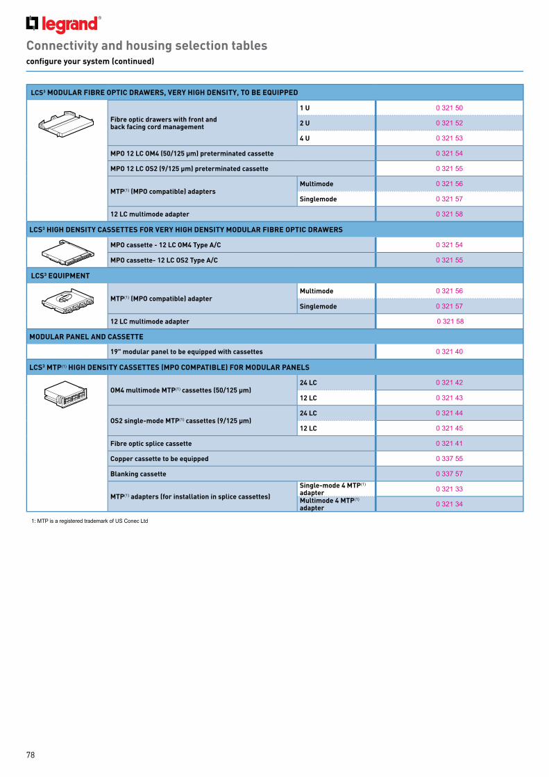
78
Connectivity and housing selection tablesconfigure your system (continued)
LCS3 MODULAR FIBRE OPTIC DRAWERS, VERY HIGH DENSITY, TO BE EQUIPPED
Fibre optic drawers with front and back facing cord management
1 U 0 321 50
2 U 0 321 52
4 U 0 321 53
MPO 12 LC OM4 (50/125 µm) preterminated cassette 0 321 54
MPO 12 LC OS2 (9/125 µm) preterminated cassette 0 321 55
MTP( 1) (MPO compatible) adaptersMultimode 0 321 56
Singlemode 0 321 57
12 LC multimode adapter 0 321 58
LCS3 HIGH DENSITY CASSETTES FOR VERY HIGH DENSITY MODULAR FIBRE OPTIC DRAWERS
MPO cassette - 12 LC OM4 Type A/C 0 321 54
MPO cassette- 12 LC OS2 Type A/C 0 321 55
LCS3 EQUIPMENT
MTP( 1) (MPO compatible) adapterMultimode 0 321 56
Singlemode 0 321 57
12 LC multimode adapter 0 321 58
MODULAR PANEL AND CASSETTE
19" modular panel to be equipped with cassettes 0 321 4 0
LCS3 MTP ( 1) HIGH DENSITY CASSETTES (MPO COMPATIBLE) FOR MODULAR PANELS
OM4 multimode MTP( 1) cassettes (50/125 µm)24 LC 0 321 4 2
12 LC 0 321 4 3
OS2 single-mode MTP ( 1) cassettes (9/125 µm)24 LC 0 321 4 4
12 LC 0 321 4 5
Fibre optic splice cassette 0 321 4 1
Copper cassette to be equipped 0 337 55
Blanking cassette 0 337 57
MTP ( 1) adapters (for installation in splice cassettes)
Single-mode 4 MTP( 1) adapter 0 321 33
Multimode 4 MTP ( 1) adapter 0 321 34
1: MTP is a reg istered trademark of US C onec L td

79
Connectivity and housing selection tablesconfigure your system (continued)
RJ 45 PATCH AND USER CORDS LCS3 Cat. 8 Cat. 6A Cat. 6
LSZH S/FTP Impedance 100 Ω
0.5 m 0 337 01 - -
1 m 0 337 02 - -
2 m 0 337 03 - -
3 m 0 337 04 - -
5 m 0 337 05 - -
8 m 0 337 06 - -
10 m 0 337 07 - -
0.5 m 0 337 21 - -
0 337 08 - -
1 m 0 337 22 - -
0 337 09 - -
2 m 0 337 23 - -
0 337 10 - -
3 m 0 337 24 - -
0 337 11 - -
5 m 0 337 25 - -
0 337 12 - -
8 m 0 337 26 - -
0 337 13 - -
10 m 0 337 27 - -
0 337 17 - -
LSOH
S/FTP Impedance 100 Ω
1 m- 0 518 7 0 -
- 0 518 66 -
2 m- 0 518 7 1 -
- 0 518 67 -
3 m- 0 518 7 2 -
- 0 518 68 -
5 m- 0 518 7 3 -
- 0 518 69 -
F/UTP Impedance 100 Ω
1 m- - 0 518 54
- - 0 518 50
2 m- - 0 518 55
- - 0 518 51
3 m- - 0 518 56
- - 0 518 52
5 m- - 0 518 57
- - 0 518 53
U/UTP Impedance 100 Ω
1 m- - 0 518 62
- - 0 518 58
2 m- - 0 518 63
- - 0 518 59
3 m- - 0 518 64
- - 0 518 60
5 m- - 0 518 65
- - 0 518 61

80
Connectivity and housing selection tablesconfigure your system (continued)
RJ 45 PATCH AND USER CORDS LCS3
LCS3 cat. 8 LCS2 cat. 6A LCS2 cat. 6
PVC
S/FTP Impedance 100 Ω
0.5 m - 0 518 16 -1 m - 0 517 8 0 0 517 522 m - 0 517 8 1 0 517 533 m - 0 517 8 2 0 517 545 m - 0 517 8 3 0 517 55
F/UTP Impedance 100 Ω
0.5 m - - 0 518 151 m - - 0 517 622 m - - 0 517 633 m - - 0 517 645 m - - 0 517 65
U/UTP Impedance 100 Ω
0.5 m - - 0 518 181 m - - 0 517 7 22 m - - 0 517 7 33 m - - 0 517 7 45 m - - 0 517 7 5
COPPER CABLES (305 M OR 500 M DRUMS) S/FTP 4 pairs 500 m 0 337 8 8 0 327 7 7 -SF/UTP 4 pairs 500 m - - 0 327 57
F/UTP4 pairs
305 m - - 0 328 56500 m 0 337 8 6 0 327 7 8 0 327 56
2 x 4 pairs 500 m - 0 328 7 8 0 327 76
F/FTP 4 pairs 500 m - 0 327 9 9 -2 x 4 pairs 500 m - 0 327 9 8 -
LCS3 FIBRE OPTIC PATCH PANELS OS 2 (UPC)
single-mode 9/125 µm
OM 4 multimode 50/125 µm
OM 3 multimode 50/125 µm
SC/SC duplex cords1 m 0 326 00 0 326 30 0 326 092 m 0 326 01 0 326 31 0 326 103 m 0 326 02 0 326 32 0 326 11
SC/LC duplex cords1 m 0 326 03 - 0 326 122 m 0 326 04 - 0 326 133 m 0 326 05 - 0 326 14
LC/LC duplex cords
0.5 m 0 326 28 0 326 33 -1 m 0 326 06 0 326 34 0 326 152 m 0 326 07 0 326 35 0 326 163 m 0 326 08 0 326 36 0 326 175 m 0 326 29 0 326 37 -
LC/LC Uniboot duplex cords reversible polarity
1 m 0 326 8 6 0 326 9 5 -2 m 0 326 8 7 0 326 9 6 -3 m 0 326 8 8 0 326 9 7 -5 m 0 326 8 9 0 326 9 8 -10 m 0 326 9 2 0 326 9 9 -
LCS3 FIBRE OPTIC CABLES (DRUMS)
Interior/exterior
4 fib re L oose 0 325 02 0 325 4 3 0 325 378 fib re L oose 0 325 03 0 325 4 4 0 325 38
6 fib reL oose 0 325 12 - -
Tig h tened - 0 326 65/66 0 325 10
12 fib reL oose 0 325 14 0 325 4 5 0 325 39
Tig h tened 0 325 50 0 326 67 0 325 11
24 fib reL oose 0 325 51 - 0 325 53
Tig h tened - 0 326 68 0 325 52
Exterior, steel rodent guard, free
4 fib re optics 0 325 23 0 325 4 6 -8 fib re optics 0 325 24 0 325 4 7 0 325 4 0
6 L oose fib re optics 0 325 13 - -12 fib re optics 0 325 15 0 325 4 8 0 325 4 124 fib re optics 0 325 25 - 0 325 4 2

81
WHITE MOSAIC RANGE RJ 45 SOCKETS
Cat. 6A Cat. 6
1 moduleSTP 0 7 65 7 3 0 7 65 63
FTP - 0 765 62
2 modulesSTP 0 7 65 7 6 0 7 65 66
FTP - 0 765 65
2 x 45° tilted modulesSTP 0 7 65 08 0 7 65 07
FTP - 0 7 65 05
90° socketsSTP - 0 7 65 9 3
FTP - 0 7 65 9 2
Anti-microbialSTP 0 7 65 8 4 0 7 65 8 3
FTP - 0 7 65 8 2
Controlled accessSTP 0 7 65 9 9 0 7 65 9 6
FTP - 0 7 65 9 5
Green flapSTP 0 7 65 24 -
FTP - 0 7 65 22
Orange flapSTP 0 7 65 25 -
FTP - 0 7 65 23
2 RJ 45 sockets FTP - 0 7 65 4 6
Copper feedthroughSTP 0 7 8 6 28 -FTP - 0 7 8 6 23
Splitter sockets
Ethernet/Ethernet FTP 0 7 65 39 0 7 65 39
Telephone/Ethernet FTP 0 7 65 37 0 7 65 37
Telephone/telephone 0 7 65 35 0 7 65 35
PoE SWITCHES AND INJECTOR
1 Gigabit PoE switch 4 RJ45 outputs 0 335 08
10/100 Mbits PoE switch 4 RJ45 outputs 0 335 03
PoE injector4 inputs/4 outputs 0 335 01
1 input/1 output 0 327 37
ZONE DISTRIBUTION BOXES Cat. 6A Cat. 6
Zone distribution boxesEquipped with 12 RJ 45 connectors
STP 0 335 4 9 0 335 4 6
FTP - 0 335 4 5
UTP - 0 335 4 4
Block of 6 RJ 45 connectors
STP - 0 335 66
FTP - 0 335 65
UTP - 0 335 64
Fibre optic accessory 0 335 20 0 335 20Zone distribution box To be equipped with 4 blocks - 0 335 4 0
Connectivity and housing selection table configure your system (continued)
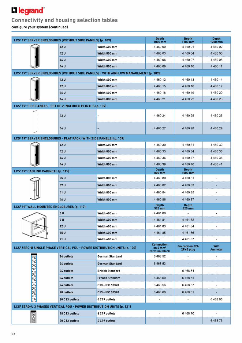
82
LCS3 19" SERVER ENCLOSURES (WITHOUT SIDE PANELS) (p. 109) Depth 1000 mm
Depth 1100 mm
Depth 1200 mm
42 U Width 600 mm 4 4 60 00 4 4 60 01 4 4 60 02
42 U Width 800 mm 4 4 60 03 4 4 60 04 4 4 60 05
46 U Width 600 mm 4 4 60 06 4 4 60 07 4 4 60 08
46 U Width 800 mm 4 4 60 09 4 4 60 10 4 4 60 11
LCS3 19" SERVER ENCLOSURES (WITHOUT SIDE PANELS) - WITH AIRFLOW MANAGEMENT (p. 109)
42 U Width 600 mm 4 4 60 12 4 4 60 13 4 4 60 14
42 U Width 800 mm 4 4 60 15 4 4 60 16 4 4 60 17
46 U Width 600 mm 4 4 60 18 4 4 60 19 4 4 60 20
46 U Width 800 mm 4 4 60 21 4 4 60 22 4 4 60 23
LCS3 19" SIDE PANELS - SET OF 2 INCLUDED PLINTHS (p. 109)
42 U - 4 4 60 24 4 4 60 25 4 4 60 26
46 U - 4 4 60 27 4 4 60 28 4 4 60 29
LCS3 19" SERVER ENCLOSURES - FLAT PACK (WITH SIDE PANELS) (p. 109)
42 U Width 600 mm 4 4 60 30 4 4 60 31 4 4 60 32
42 U Width 800 mm 4 4 60 33 4 4 60 34 4 4 60 35
46 U Width 600 mm 4 4 60 36 4 4 60 37 4 4 60 38
46 U Width 800 mm 4 4 60 39 4 4 60 4 0 4 4 60 4 1
LCS3 19" CABLING CABINETS (p. 115) Depth 800 mm
Depth 1000 mm
25 U Width 800 mm 4 4 60 8 0 4 4 60 8 1 -
37 U Width 800 mm 4 4 60 8 2 4 4 60 8 3 -
41 U Width 800 mm 4 4 60 8 4 4 4 60 8 5 -
46 U Width 800 mm 4 4 60 8 6 4 4 60 8 7 -
LCS3 19" WALL MOUNTED ENCLOSURES (p. 117) Depth 525 mm
Depth 625 mm
6 U Width 600 mm 4 4 61 8 0 - -
9 U Width 600 mm 4 4 61 8 1 4 4 61 8 2 -
12 U Width 600 mm 4 4 61 8 3 4 4 61 8 4 -
15 U Width 600 mm 4 4 61 8 5 4 4 61 8 6 -
21 U Width 600 mm - 4 4 61 8 7 -
LCS3 ZERO-U SINGLE PHASE VERTICAL PDU - POWER DISTRIBUTION UNITS (p. 120)Connectionon 6 mm2
terminal block
3m cord on 32A 2P+E plug
With Ammeter
3 m
24 outlets German Standard 6 4 68 52 - -
24 outlets German Standard 6 4 68 53 - -
24 outlets British Standard - 6 4 68 54 -
24 outlets French Standard 6 4 68 50 6 4 68 51 -
24 outlets C13 - IEC 60320 6 4 68 56 6 4 68 57 -
20 outlets C13 - IEC 60320 6 4 68 60 6 4 68 61 -
20 C13 outlets 4 C19 outlets - - 6 4 68 65
LCS3 ZERO-U 3 PHASES VERTICAL PDU - POWER DISTRIBUTION UNITS (p. 121)
3 m
AM
PA
MP
AM
P
18 C13 outlets 6 C19 outlets - 6 4 68 7 0 -
20 C13 outlets 4 C19 outlets - - 6 4 68 7 5
Connectivity and housing selection tablesconfigure your system (continued)

83
Connectivity and housing selection tablesconfigure your system (continued)
LCS3 1 U 19" SINGLE PHASE PDU - POWER DISTRIBUTION UNITS (p. 122) Connection on 6 mm2
terminal block 3 m cord on 16 A plug
10 outlets C13 - IEC 60320 6 4 68 14 -
12 outlets C13 - IEC 60320 - 6 4 68 15
8 outlets C13 (6) and C19 (2) - IEC 60320 6 4 68 09 -
6 outlets C13 - IEC 60320 6 4 68 07 -
LCS3 1 U 19" SINGLE PHASE PDU - POWER DISTRIBUTION UNITS (p. 123) With MCB With 30 mA RCCB
With Surge protection
With Ammeter
6 outlets C13 (6) - On terminal block - - - 6 4 68 4 3
7 outlets C13 (6) and C19 (1) - On terminal block - - - 6 4 68 4 5
6 outlets C19 (6) - On terminal block - - - 6 4 68 4 4
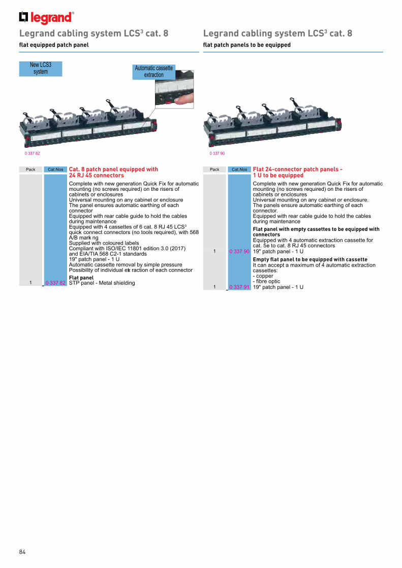
84
Legrand cabling system LCS3 cat. 8flat patch panels to be equipped
Legrand cabling system LCS3 cat. 8flat equipped patch panel
0 337 9 00 337 8 2
N ew L C S3 system Automatic cassette
ex traction
Pack C at.N os Cat. 8 patch panel equipped with 24 RJ 45 connectorsC omplete with new g eneration Q uick- Fix for automatic mounting ( no screws req uired) on th e risers of cab inets or enclosuresUniversal mounting on any cab inet or enclosure Th e panel ensures automatic earth ing of each connector E q uipped with rear cab le g uide to h old th e cab les during maintenance E q uipped with 4 cassettes of 6 cat. 8 RJ 4 5 L C S3 q uick- connect connectors ( no tools req uired) , with 568 A/B marki ng Supplied with coloured lab els C ompliant with I SO/I E C 118 01 edition 3.0 ( 2017 ) and E I A/TI A 568 C 2- 1 standards 19 " patch panel - 1 U Automatic cassette removal b y simple pressure Possib ility of individual ext raction of each connectorFlat panel
1 0 337 8 2 STP panel - Metal sh ielding
Pack C at.N os Flat 24-connector patch panels - 1 U to be equippedC omplete with new g eneration Q uick- Fix for automatic mounting ( no screws req uired) on th e risers of cab inets or enclosuresUniversal mounting on any cab inet or enclosure. Th e panels ensure automatic earth ing of each connector. E q uipped with rear cab le g uide to h old th e cab les during maintenance Flat panel with empty cassettes to be equipped with connectorsE q uipped with 4 automatic ex traction cassette for cat. 5e to cat. 8 RJ 4 5 connectors
1 0 337 9 0 19 " patch panel - 1 UEmpty flat panel to be equipped with cassetteI t can accept a max imum of 4 automatic ex traction cassettes:- copper- fibre optic
1 0 337 9 1 19 " patch panel - 1 U

85
0 337 9 20 337 550 337 56 0 337 59
0 337 8 5 0 337 57 0 337 58
Legrand cabling system LCS3 cat. 8equipment and accessories
Legrand cabling system LCS3 cat. 8angled patch panel to be equipped with connectors
Pack C at.N os Angled 24-connector patch panel - 1 UC omplete with new g eneration Q uick- Fix for automatic mounting ( no screws req uired) on th e risers of cab inets or enclosuresUniversal mounting on any cab inet or enclosure Th e panel ensures automatic earth ing of each connector E q uipped with rear cab le g uide to h old th e cab les during maintenanceAngled panel to be equipped with connectorsI t can accept up to 24 cat. 5e to cat. 8 RJ 4 5 connectors
1 0 337 9 2 19 " panel - 1 U
Cat. 8 RJ 45 connectors for flat and angled STP panelQ uick - connect connection ( no tools req uired) , with 568 A/B mark ingSupplied with coloured lab elsC ompliant with th e following standards I SO/I E C 118 01 edition 3.0 ( 2017 ) and E I A/TI A 568 C 2- 1
1 0 337 8 5 Set of 6 RJ 4 5 connectors For installation in the cassettes of flat or angled panels
Pack C at.N os Common accessories for flat and angled panels
Port blanking modules10 0 337 56 Divisib le 6 port b lanki ng plate
for sealing from 1 to 6 portsCord management
1 0 337 59 2 cord manag ement for use with new g eneration Q uick - Fix Th ey provide side cord manag ement
Specific accessories for flat panelsCassette for flat panels to be equipped
1 0 337 55 E mpty removab le cassette to b e eq uipped with connectors. I t can accept 6 cat. 5e to cat. 8 connectors.E x traction b y simple pressure of th e cassette mak ing installation and maintenance easierBlanking cassette
1 0 337 57 Used to b lank th e panel
Specific accessories for angled panelsAngled panel cover
1 0 337 58 For optimised management of the air flow inside the cab inet
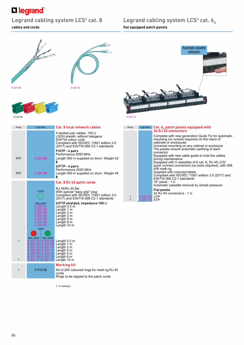
86
Legrand cabling system LCS3 cat. 8cables and cords
0 518 9 0
0 337 8 8 0 337 03
0 337 7 2
Legrand cabling system LCS3 cat. 6Aflat equipped patch panels
Automatic cassette ex traction
Pack C at.N os Cat. 8 local network cables4 twisted pair cab les, 100 Ω L SOH sh eath : with out h alog ens E I A/TI A colour codeC ompliant with I SO/I E C 118 01 edition 3.0 ( 2017 ) and E I A/TI A 568 C 2- 1 standardsF/UTP - 4 pairsPerformance 2000 MHz
5001 0 337 8 6 L eng th 500 m supplied on drum. W eig h t 4 2 kgS/FTP - 4 pairsPerformance 2000 MHz
5001 0 337 8 8 L eng th 500 m supplied on drum. W eig h t 4 5 kg
Cat. 8 RJ 45 patch cords
L SZ HRJ 45/RJ 45 flatW ith special " easy g rip" plugC ompliant with I SO/I E C 118 01 edition 3.0 ( 2017 ) and E I A/TI A 568 C 2- 1 standards
RAL 6027 S/FTP shielded, impedance 100 Ω0 337 01 L eng th 0.5 m0 337 02 L eng th 1 m0 337 03 L eng th 2 m0 337 04 L eng th 3 m0 337 05 L eng th 5 m0 337 06 L eng th 8 m0 337 07 L eng th 10 m
L SZ H
RAL 3020 RAL 60261 0 337 21 0 337 08 L eng th 0.5 m
0 337 22 0 337 09 L eng th 1 m0 337 23 0 337 10 L eng th 2 m0 337 24 0 337 11 L eng th 3 m0 337 25 0 337 12 L eng th 5 m0 337 26 0 337 13 L eng th 8 m
1 0 337 27 0 337 17 L eng th 10 mMarking kit
1 0 518 9 0 K it of 200 coloured ring s for marki ng RJ 4 5 cords Ring s to b e clipped to th e patch cords
Pack C at.N os Cat. 6A patch panels equipped with 24 RJ 45 connectorsC omplete with new g eneration Q uick- Fix for automatic mounting ( no screws req uired) on th e risers of cab inets or enclosuresUniversal mounting on any cab inet or enclosure Th e panels ensure automatic earth ing of each connectorE q uipped with rear cab le g uide to h old th e cab les during maintenanceE q uipped with 4 cassettes of 6 cat. 6A RJ 4 5 L C S3 q uick- connect connectors ( no tools req uired) , with 568 A/B marki ngSupplied with coloured lab elsC ompliant with I SO/I E C 118 01 edition 3.0 ( 2017 ) and E I A/TI A 568 C 2- 1 standards19 " panel - 1 U Automatic cassette removal b y simple pressureFlat panels24 RJ 4 5 connectors - 1 U
1 0 337 7 0 UTP1 0 337 7 2 STP
1: in metre( s)

87
Legrand cabling system LCS3 cat. 6Aflat patch panels to be equipped
Legrand cabling system LCS3 cat. 6Aangled patch panels to be equipped with connectors
0 337 9 0
0 337 9 3
0 337 9 2
0 337 9 4
0 337 7 5
Pack C at.N os Flat 24-connector patch panels - 1 U to be equippedC omplete with new g eneration Q uick- Fix for automatic mounting ( no screws req uired) on th e risers of cab inets or enclosuresUniversal mounting on any cab inet or enclosure Th e panels ensure automatic earth ing of each connectorE q uipped with rear cab le g uide to h old th e cab les during maintenanceFlat panel with empty cassettes to be equipped with connectorsE q uipped with 4 automatic ext raction cassettes for cat. 5e to cat. 8 RJ 4 5 connectors
1 0 337 9 0 19 " panel - 1 UEmpty flat panel to be equipped with cassettesI t can accept a max imum of 4 automatic ex traction cassettes: - copper- fibre optic
1 0 337 9 1 19 " panel - 1 U
Flat high density 48-connector patch panel - 1 U to be equipped Universal mounting on any cab inet or enclosureTh e panel ensures automatic earth ing of each connectorE q uipped with rear cab le g uide to h old th e cab les during maintenance Automatic cassette removal b y simple pressure Possib ility of removing each connector individually
1 0 337 9 3 19 " panel - 1 U
Pack C at.N os Angled 24-connector patch panel - 1 UC omplete with new g eneration Q uick- Fix for automatic mounting ( no screws req uired) on th e risers of cab inets or enclosuresUniversal mounting on any cab inet or enclosure Th e panel ensures automatic earth ing of each connectorE q uipped with rear cab le g uide to h old th e cab les during maintenanceAngled panel to be equipped with connectorsI t can accept up to 24 cat. 5e to cat. 8 RJ 4 5 connectors
1 0 337 9 2 19 " panel - 1 U
Angled high density 48-connector patch panel - 1 U to be equipped C omplete with new g eneration Q uick- Fix for automatic mounting ( no screws req uired) on th e risers of cab inets or enclosuresUniversal mounting on any cab inet or enclosureTh e panel ensures automatic earth ing of each connectorE q uipped with rear cab le g uide to h old th e cab les during maintenance Angled panel to be equipped with connectorsI t can accept up to 4 8 cat. 5e to cat. 6A RJ 4 5 connectors
1 0 337 9 4 19 " panel - 1 U
High density cat. 6A RJ 45 connectorsCat. 6A RJ 45 connectors for flat and angled STP panelsQ uick- connect connection ( no tools req uired) , with 568 A/B marki ngSupplied with coloured lab elsC ompliant with I SO/I E C 118 01 edition 3.0 ( 2017 ) and E I A/TI A 568 C 2- 1 standardsFor equipment to be installed in the cassettes of flat or ang led panelsSet of 6 cat. 6A RJ 4 5 connectors
1 0 337 7 3 UTP1 0 337 7 5 STP

88
Legrand cabling system LCS3 cat. 6Aequipment and accessories
0 337 550 337 56 0 337 59 0 337 57 0 337 58
Pack C at.N os Common accessories for flat and angled panelsPort blanking modules
10 0 337 56 Divisib le 6 port b lanki ng plateFor sealing from 1 to 6 portsCord management
1 0 337 59 For use with new g eneration Q uick- Fix; th ey provide side cord manag ement
Specific accessories for flat panelsCassette for flat panels to be equipped
1 0 337 55 E mpty removab le cassette to b e eq uipped with connectors. I t can accept 6 cat. 5e to cat. 8 connectorsE x traction b y simple pressure of th e cassette mak ing installation and maintenance easierPossib ility of removing each connector individuallyHigh density cassette for flat panels to be equipped
1 0 337 9 5 E mpty removab le cassette to b e eq uipped with connectors; it can accept 12 cat. 5e to cat. 6A connectorsE xt raction b y simple pressure of th e cassette, maki ng installation and maintenance easierBlanking cassette
1 0 337 57 Used to b lank th e panel
Pack C at.N os Specific accessories for angled panelsAngled panel cover
1 0 337 58 For optimised management of the air flow inside the cab inet

89
0 327 7 7
Pack C at.N os Cables for local networks cat. 6A
C ab les 4 pairs or 2 x 4 twisted pairs 100 oh ms L SZ H sleeve: h alog en- freeY ellow RAL 1018C olour code TI A/E I AC onform to standards I SO/I E C 118 01 E d. 2.0, E N 5017 3- 1 and TI A/E I A 568 CPerformance 500 MHzL SZ HU/UTP - 4 pairsPerformance 500 MHz
5001 0 327 8 7 L eng th 500 m Supplied on reel. W eig h t 25 k gF/UTP - 4 pairsPerformance 500 MHz
5001 0 327 7 8 L eng th 500 m Supplied on reel. W eig h t 25 k gF/UTP - 2 x 4 pairsPerformance 500 MHz
5001 0 328 7 8 L eng th 500 m Supplied on reel. W eig h t 65 k gS/FTP - 4 pairsPerformance 600 MHz
5001 0 327 7 7 L eng th 500 m Supplied on reel. W eig h t 30 k g
Pack C at.N os RJ 45 patch cords and user cords cat. 6A
PV C
RJ 4 5 - RJ 4 5 rig h tC onform to standards I SO/I E C 118 01 E d. 2.0, E N 5017 3- 1 and TI A/E I A 568 CU/UTP unscreened impedance 100 Ω
1 0 518 8 2 L eng th 1 m1 0 518 8 3 L eng th 2 m1 0 518 8 4 L eng th 3 m1 0 518 8 5 L eng th 5 m
L SZ H
1 0 518 7 8 L eng th 1 m1 0 518 7 9 L eng th 2 m1 0 518 8 0 L eng th 3 m1 0 518 8 1 L eng th 5 m
1 0 518 7 4 L eng th 1 m1 0 518 7 5 L eng th 2 m1 0 518 7 6 L eng th 3 m1 0 518 7 7 L eng th 5 m
PV C S/FTP shielded impedance 100 Ω
1 0 518 16 L eng th 0.5 m5 0 517 8 0 L eng th 1 m5 0 517 8 1 L eng th 2 m5 0 517 8 2 L eng th 3 m5 0 517 8 3 L eng th 5 m
L SZ H
1 0 518 7 0 L eng th 1 m1 0 518 7 1 L eng th 2 m1 0 518 7 2 L eng th 3 m1 0 518 7 3 L eng th 5 m
1 0 518 66 L eng th 1 m1 0 518 67 L eng th 2 m1 0 518 68 L eng th 3 m1 0 518 69 L eng th 5 m
0 517 8 2
N ew plugC onvenient for g ripping
Legrand cabling system LCS3 cat. 6Acables and cords
1: in metre( s)

90
Pack C at.N os Keystone RJ 45 sockets cat. 6a
10 0 331 54 STP sock et - metal sh ielding 360° with fast connection th ank s to integ rated crimping
10 0 331 55 UTP sock et - with fast connection th ank s to integ rated crimping
Surface-mounting 1 or 2 ports box1 6 327 7 9 For k eystone connectors
Provides a solution for th e integ ration of a k eystone in surface- mounting installationsCan be fixed on table or in association with mini- trunk ing
C an b e integ rated in all supports ( see L eg rand g eneral catalog ) Mech anisms to b e eq uipped with support frames ( see L eg rand g eneral catalog ) and plates ( see L eg rand g eneral catalog )W ith L C S3 connector with fast connection th ank s to integ rated crimping tak e AW G 22 sing le- core cab les up to AW G 26 and AW G multicore cab lesC ontacts mark ed with dual colour code and wiring sch emes T568 A and T 568 BC onform to standards I SO/I E C 118 01 E d. 2.0, amendment 2, E N 5017 3- 1 and TI A/E I A 568 C
Legrand cabling system LCS3 cat. 6ARJ 45 sockets - Arteor
5 7 23 575 7 23 59 5 7 23 585 7 23 06 6 327 7 9
Pack C at.N os Arteor RJ 45 socket cat. 6A
360° metal sh ieldingSTP - 1 module
10 5 7 23 06 W h ite10 5 7 28 06 Mag nesium10 5 7 23 52 W h ite with g reen sh utter10 5 7 28 52 Mag nesium with g reen sh utter10 5 7 23 51 W h ite with orang e sh utter10 5 7 28 51 Mag nesium with orang e sh utter
STP with controlled access - 2 modulesSupplied with 2 k eys for 5 sock ets
5 5 7 23 50 W h ite with red sh utter5 5 7 28 50 Mag nesium with red sh utter
UTP - 1 module10 5 7 23 4 9 W h ite10 5 7 28 4 9 Mag nesium10 5 7 23 59 W h ite with g reen sh utter10 5 7 28 59 Mag nesium with g reen sh utter10 5 7 23 58 W h ite with orang e sh utter10 5 7 28 58 Mag nesium with orang e sh utter
UTP with controlled access - 2 modulesSupplied with 2 k eys for 5 sock ets
5 5 7 23 57 W h ite with red sh utter5 5 7 28 57 Mag nesium with red sh utter
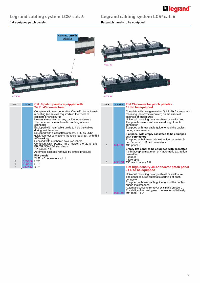
91
Legrand cabling system LCS3 cat. 6flat equipped patch panels
0 337 61
Automatic cassette extraction
Pack C at.N os Cat. 6 patch panels equipped with 24 RJ 45 connectorsComplete with new generation Quick-Fix for automatic mounting ( no screws req uired) on th e risers of cab inets or enclosuresUniversal mounting on any cab inet or enclosure Th e panels ensure automatic earth ing of each connectorE q uipped with rear cab le g uide to h old th e cab les during maintenanceE q uipped with 4 cassettes of 6 cat. 6 RJ 4 5 L C S3 q uick- connect connectors ( no tools req uired) , with 568 A/B marki ngSupplied with numb ered coloured lab elsC ompliant with I SO/I E C 118 01 edition 3.0 ( 2017 ) and E I A/TI A 568 C 2- 1 standards19 " panel - 1 U Automatic cassette removal b y simple pressureFlat panels24 RJ 4 5 connectors - 1 U
1 0 337 60 UTP1 0 337 61 FTP1 0 337 62 STP
Legrand cabling system LCS3 cat. 6flat patch panels to be equipped
0 337 9 0
0 337 9 3
Pack C at.N os Flat 24-connector patch panels - 1 U to be equippedComplete with new generation Quick-Fix for automatic mounting ( no screws req uired) on th e risers of cab inets or enclosuresUniversal mounting on any cab inet or enclosure. Th e panels ensure automatic earth ing of each connector. E q uipped with rear cab le g uide to h old th e cab les during maintenance Flat panel with empty cassettes to be equipped with connectorsEquipped with 4 automatic extraction cassettes for cat. 5e to cat. 8 RJ 4 5 connectors
1 0 337 9 0 19 ” panel - 1 Umpty at panel to be e uipped with cassettes
It can accept a maximum of 4 automatic extraction cassettes:- copper- fibre optic
1 0 337 9 1 19 " patch panel - 1 U
Flat high density 48-connector patch panel - 1 U to be equipped Universal mounting on any cab inet or enclosure Th e panel ensures automatic earth ing of each connector E q uipped with rear cab le g uide to h old th e cab les during maintenanceAutomatic cassette removal b y simple pressure Possib ility of removing each connector individually
1 0 337 9 3 19 " panel - 1 U
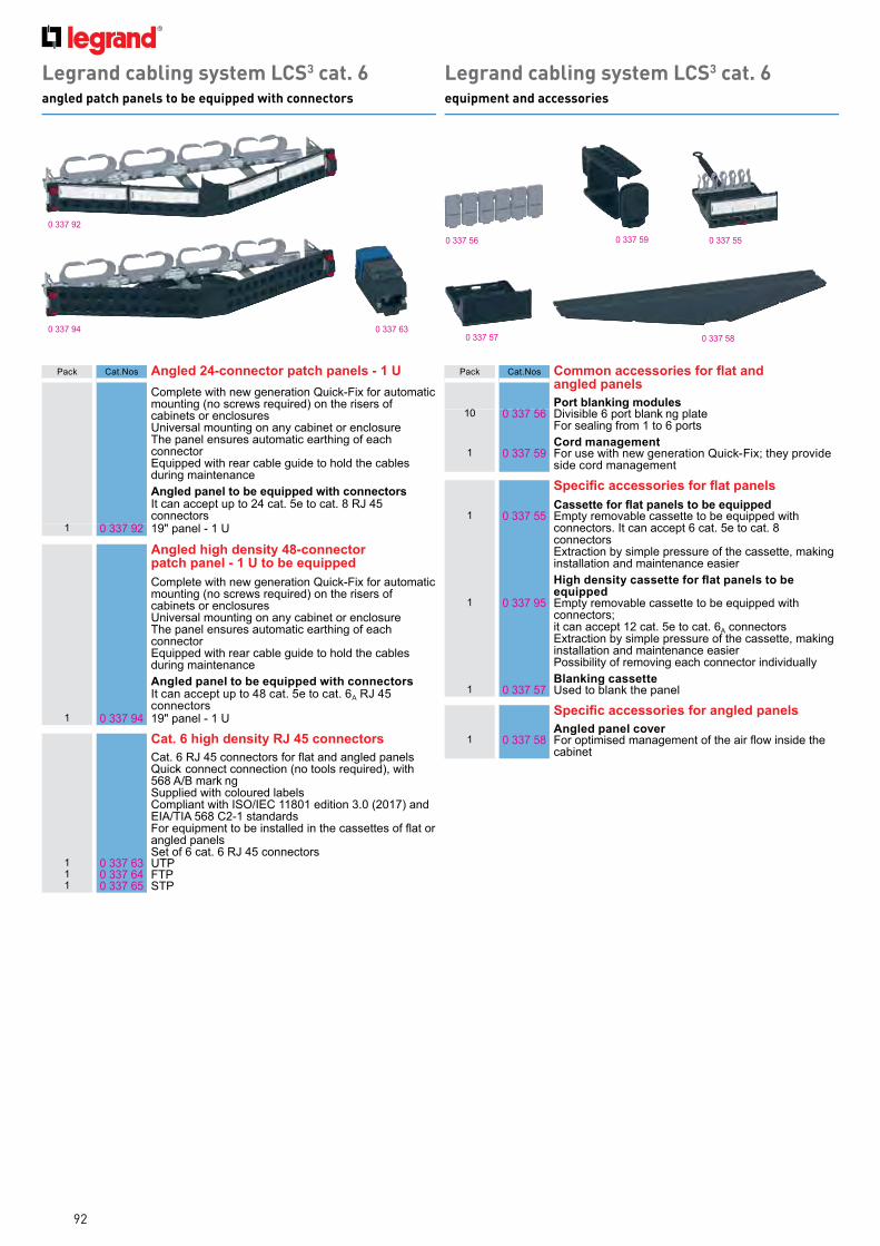
92
Legrand cabling system LCS3 cat. 6angled patch panels to be equipped with connectors
0 337 9 2
0 337 9 4 0 337 63
Legrand cabling system LCS3 cat. 6equipment and accessories
0 337 550 337 56 0 337 59
0 337 57 0 337 58
Pack C at.N os Angled 24-connector patch panels - 1 UComplete with new generation Quick-Fix for automatic mounting ( no screws req uired) on th e risers of cab inets or enclosuresUniversal mounting on any cab inet or enclosure Th e panel ensures automatic earth ing of each connectorE q uipped with rear cab le g uide to h old th e cab les during maintenanceAngled panel to be equipped with connectorsI t can accept up to 24 cat. 5e to cat. 8 RJ 4 5 connectors
1 0 337 9 2 19 " panel - 1 U
Angled high density 48-connector patch panel - 1 U to be equipped Complete with new generation Quick-Fix for automatic mounting ( no screws req uired) on th e risers of cab inets or enclosuresUniversal mounting on any cab inet or enclosureTh e panel ensures automatic earth ing of each connectorE q uipped with rear cab le g uide to h old th e cab les during maintenance Angled panel to be equipped with connectorsI t can accept up to 4 8 cat. 5e to cat. 6A RJ 4 5 connectors
1 0 337 9 4 19 " panel - 1 U
Cat. 6 high density RJ 45 connectorsCat. 6 RJ 45 connectors for flat and angled panelsQ uick- connect connection ( no tools req uired) , with 568 A/B marki ngSupplied with coloured lab elsC ompliant with I SO/I E C 118 01 edition 3.0 ( 2017 ) and E I A/TI A 568 C 2- 1 standardsFor equipment to be installed in the cassettes of flat or ang led panelsSet of 6 cat. 6 RJ 4 5 connectors
1 0 337 63 UTP1 0 337 64 FTP1 0 337 65 STP
Pack C at.N os ommon accessories for at and angled panelsPort blanking modules
10 0 337 56 Divisib le 6 port b lanki ng plateFor sealing from 1 to 6 portsCord management
1 0 337 59 For use with new generation Quick-Fix they provide side cord manag ement
pecific accessories for at panelsassette for at panels to be e uipped
1 0 337 55 E mpty removab le cassette to b e eq uipped with connectors. I t can accept 6 cat. 5e to cat. 8 connectorsExtraction by simple pressure of the cassette, making installation and maintenance easier
igh density cassette for at panels to be equipped
1 0 337 9 5 E mpty removab le cassette to b e eq uipped with connectors it can accept 12 cat. 5e to cat. 6A connectorsExtraction by simple pressure of the cassette, making installation and maintenance easier Possib ility of removing each connector individuallyBlanking cassette
1 0 337 57 Used to b lank th e panel
pecific accessories for angled panelsAngled panel cover
1 0 337 58 For optimised management of the air flow inside the cab inet

93
Legrand cabling system LCS3 cat. 6cables and cords
0 517 620 327 54
Pack C at.N os Cables for local networks cat. 6Cables 4 pairs or 2 x 4 twisted pairs 100 oh ms B lue RAL 5015C olour code TI A/E I AC onform to standards I SO/I E C 118 01 E d. 2.0, E N 5017 3- 1 and TI A/E I A 568 CU/UTP - 4 pairsL SZ H PV C
3051 0 327 54 L eng th 305 m Supplied in cardboard box. Weight 16 kg
5001 0 328 61 L eng th 500 m Supplied on reel. W eig h t 18 k g
3051 0 327 55 L eng th 305m Supplied in cardboard box. Weight 13 kg
F/UTP - 4 pairs3051 0 328 56 L eng th 305 m
Supplied on reel. W eig h t 17 k g5001 0 327 56 L eng th 500 m
Supplied on reel. W eig h t 25 k gF/UTP - 4 pairs
3051 0 328 57 L eng th 305 m Supplied in cardboard box. Weight 17 kg
5001 0 327 58 L eng th 500 m Supplied on reel. W eig h t 25 k gF/UTP - 2 x 4 pairs
5001 0 327 7 6 L eng th 500 m Supplied on reel. W eig h t 4 8 k gSF/UTP - 4 pairs
5001 0 327 57 L eng th 500 m Supplied on reel. W eig h t 29 k g
5001 0 327 59 L eng th 500 m Supplied on reel. W eig h t 30 k g
0 327 9 8 F/FTP - 2 x 4 pairsL eng th 500 m W eig h t 62 k g
0 327 9 9 F/FTP - 4 pairsL eng th 500 m W eig h t 25, 2 k g1: in metre( s)
Pack C at.N os RJ 45 patch cords and user cords cat. 6RJ 4 5 - RJ 4 5 rig h t
PV CU/UTP unscreened impedance 100 Ω
1 0 518 18 L eng th 0.5 m1 0 517 7 2 L eng th 1 m1 0 517 7 3 L eng th 2 m1 0 517 7 4 L eng th 3 m1 0 517 7 5 L eng th 5 m
L SZ H
1 0 518 62 0 518 58 L eng th 1 m1 0 518 63 0 518 59 L eng th 2 m1 0 518 64 0 518 60 L eng th 3 m1 0 518 65 0 518 61 L eng th 5 m
PV C F/UTP screened impedance 100 Ω
1 0 518 15 L eng th 0.5 m1 0 517 62 L eng th 1 m1 0 517 63 L eng th 2 m1 0 517 64 L eng th 3 m1 0 517 65 L eng th 5 m
L SZ H
1 0 518 54 0 518 50 L eng th 1 m1 0 518 55 0 518 51 L eng th 2 m1 0 518 56 0 518 52 L eng th 3 m1 0 518 57 0 518 53 L eng th 5 m
PV C SF/UTP shielded impedance 100 Ω
5 0 517 52 L eng th 1 m5 0 517 53 L eng th 2 m5 0 517 54 L eng th 3 m5 0 517 55 L eng th 5 m
N ew plugC onvenient for g ripping
PE
0 328 29 U/UTP - 4 pairsL eng th 500 mSupplied on reelGel filled PE acket

94
Legrand cabling system LCS3 cat. 6RJ 45 sockets - Arteor Programme
Pack C at.N os Arteor RJ 45 sockets cat. 6Mech anisms supplied with sq uare rock er plates, to b e eq uipped with support frames ( see L eg rand g eneral catalog ) and plates ( see L eg rand g eneral catalog )UTP - 1 module
10 5 7 23 02 W h ite10 5 7 28 02 Mag nesium10 5 7 23 54 W h ite with orang e b lank10 5 7 28 54 Mag nesium with orang e b lank10 5 7 23 55 W h ite with g reen b lank10 5 7 28 55 Mag nesium with g reen b lank
UTP - 2 modules10 5 7 23 14 W h ite - sq uare version10 5 7 28 14 Mag nesium - sq uare version
UTP with controlled access - 2 modulesSupplied with 2 k eys for 5 sock ets
5 5 7 23 53 W h ite with red b lank5 5 7 28 53 Mag nesium with red b lank
UTP retractable RJ 45 sockets - 4 modulesW ith integ rated retractab le cord ( 0.9 m) W inds up automatically with a push b utton
1 5 7 23 39 W h ite1 5 7 28 39 Mag nesium
FTP - 1 module10 5 7 23 22 W h ite10 5 7 28 22 Mag nesium
FTP - 2 modules10 5 7 23 16 W h ite10 5 7 28 16 Mag nesium
Shielded STP - 1 module10 5 7 23 23 W h ite10 5 7 28 23 Mag nesium
Shielded STP - 2 modules10 5 7 23 17 W h ite10 5 7 28 17 Mag nesium
C an b e integ rated in all supports ( see L eg rand g eneral catalog ) Mech anisms to b e eq uipped with support frames ( see L eg rand g eneral catalog ) and plates ( see L eg rand g eneral catalog )W ith L C S3 connector with fast connection th ank s to integ rated crimping tak e AW G 22 sing le- core cab les up to AW G 26 and AW G multicore cab lesC ontacts mark ed with dual colour code and wiring sch emes T568 A and T 568 BC onform to standards I SO/I E C 118 01 E d. 2.0, amendment 2, E N 5017 3- 1 and TI A/E I A 568 C
5 7 28 02 5 7 28 14

95
Legrand cabling system LCS3 category 6RJ 45 sockets - Arteor, Soliroc and Plexo
C an b e integ rated in all supports ( see L eg rand g eneral catalog )W ith L C S3 connector with fast connection th ank s to integ rated crimping tak e AW G 22 sing le- core cab les up to AW G 26 and AW G multicore cab lesC ontacts mark ed with dual colour code and wiring sch emes T568 A and T 568 BC onform to standards I SO/I E C 118 01 E d. 2.0, amendment 2, E N 5017 3- 1 and TI A/E I A 568 C
0 69 5 69 0 331 8 16 327 7 9
Pack C at.N os Keystone RJ 45 socket cat. 610 0 331 8 1 UTP sock et with fast connection - b lack10 0 331 61 UTP sock et with fast connection - wh ite30 6 327 05 UTP sock et type 110 - wh ite
Surface-mounting 1 or 2 ports box1 6 327 7 9 For k eystone connectors
Provides a solution for th e integ ration of a k eystone in surface- mounting installationsCan be fixed on table or in association with mini- trunk ing
Soliroc RJ 45 socket cat. 6 - IK 10FTP - 2 modules
1 0 7 7 8 9 1 I P 20 - I K 10 For at- risk areas or areas with no surveillance
Plexo RJ 45 sockets cat. 6 - IP 55 closed ap
RJ 45 socketsProtection ag ainst water, dustFor industrial sites
5 0 69 5 69 G rey/wh ite FTP sock et
1 0 69 5 61 G rey/wh ite UTP sock et
Adaptor for RJ 45 socket 1 0 69 5 8 1 RJ 4 5 to b e ordered separately
Weatherproofing ensured (IP 44) plug inserted
G rey/wh ite
Plexo 66 RJ 45 socket cat. 6 - IP 66 - IK 08FTP socket
1 0 9 04 67
9 contactsWeatherproofing ensured (IP 66) with plug inserted I nclined 9 0°
G rey RAL 7 016/T029
101010
E MK E Y STON E L W E
E MK E Y STON E L UG
E MK E Y STON E L B L
W h iteUrb an G reyB lack
Suits Legrand LCS2 tooless j acks

96
0 337 51
Legrand cabling system LCS3 cat. 5eflat equipped patch panels
Legrand cabling system LCS3 cat. 5eflat patch panels to be equipped
0 337 9 0
0 337 9 3
Pack C at.N os Cat. 5e patch panels equipped with 24 RJ 45 connectorsComplete with new generation Quick-Fix for automatic mounting ( no screws req uired) on th e risers of cab inets or enclosuresUniversal mounting on any cab inet or enclosure Th e panels ensure automatic earth ing of each connectorE q uipped with rear cab le g uide to h old th e cab les during maintenanceE q uipped with 4 cassettes of 6 cat. 5e RJ 4 5 L C S3 q uick- connect connectors ( no tools req uired) , with 568 A/B marki ngSupplied with coloured lab elsC ompliant with I SO/I E C 118 01 edition 3.0 ( 2017 ) and E I A/TI A 568 C 2- 1 standards19 " panel - 1 U Automatic cassette removal b y simple pressure Possib ility of removing each connector individuallyFlat panel with empty cassettes to be equipped with connectors24 RJ 4 5 connectors - 1 U
1 0 337 50 UTP1 0 337 51 FTP
Pack C at.N os Flat 24-connector patch panels - 1 U to be equippedComplete with new generation Quick-Fix for automatic mounting ( no screws req uired) on th e risers of cab inets or enclosuresUniversal mounting on any cab inet or enclosure. Th e panels ensure automatic earth ing of each connector. E q uipped with rear cab le g uide to h old th e cab les during maintenanceFlat panel with empty cassettes to be equipped with connectorsEquipped with 4 automatic extraction cassettes for cat. 5e to cat. 8 RJ 4 5 connectors
1 0 337 9 0 19 " panel - 1 Umpty at panel to be e uipped with cassettes
It can accept a maximum of 4 automatic extraction cassettes:- copper- fibre optic
1 0 337 9 1 19 " panel - 1 U
Flat high density 48-connector patch panel - 1 U to be equipped Universal mounting on any cab inet or enclosure Th e panel ensures automatic earth ing of each connector E q uipped with rear cab le g uide to h old th e cab les during maintenanceAutomatic cassette removal b y simple pressure
1 0 337 9 3 19 " panel - 1 U

97
Legrand cabling system LCS3 cat. 5eangled patch panels to be equipped with connectors
Legrand cabling system LCS3 cat. 5eequipment and accessories
0 337 9 2
0 337 9 4 0 337 53
0 337 550 337 56 0 337 59
0 337 57 0 337 58
Pack C at.N os Angled 24-connector patch panel - 1 UComplete with new generation Quick-Fix for automatic mounting ( no screws req uired) on th e risers of cab inets or enclosuresUniversal mounting on any cab inet or enclosure Th e panel ensures automatic earth ing of each connector E q uipped with rear cab le g uide to h old th e cab les during maintenanceAngled panel to be equipped with connectorsI t can accept up to 24 cat. 5e to cat. 8 RJ 4 5 connectors
1 0 337 9 2 19 " panel - 1 U
Angled high density 48-connector patch panel - 1 U to be equipped Complete with new generation Quick-Fix for automatic mounting ( no screws req uired) on th e risers of cab inets or enclosuresUniversal mounting on any cab inet or enclosureTh e panel ensures automatic earth ing of each connector E q uipped with rear cab le g uide to h old th e cab les during maintenance Ang led panel to b e eq uipped with connectors I t can accept up to 4 8 cat. 5e to cat. 6A RJ 4 5 connectors
1 0 337 9 4 19 " panel - 1 U
Cat. 5e High density RJ 45 connectorsCat. 5e RJ 45 connectors for flat and angled panelQ uick- connect connection ( no tools req uired) , with 568 A/B marki ngSupplied with coloured lab elsC ompliant with I SO/I E C 118 01 edition 3.0 ( 2017 ) and E I A/TI A 568 C 2- 1 standards For equipment to be installed in the cassettes of flat or ang led panelsSet of 6 cat. 5e RJ 4 5 connectors
1 0 337 53 UTP1 0 337 54 FTP
Pack C at.N os ommon accessories for at and angled panelsPort blanking modules
10 0 337 56 Divisib le 6 port b lanki ng plate for sealing from 1 to 6 portsCord management
1 0 337 59 For use with new generation Quick-Fix Th ey provide side cord manag ement
pecific accessories for at panelsassette for at panels to be e uipped
1 0 337 55 E mpty removab le cassette to b e eq uipped with connectors. I t can accept 6 cat. 5e to cat. 8 connectors.Extraction by simple pressure of the cassette, mak ing installation and maintenance easier Possib ility of removing each connector individually
igh density cassette for at panels to be equipped
1 0 337 9 5 E mpty removab le cassette to b e eq uipped with connectors it can accept 12 cat. 5e to cat. 6A connectorsExtraction by simple pressure of the cassette, mak ing installation and maintenance easier Possib ility of removing each connector individuallyBlanking cassette
1 0 337 57 Used to b lank th e panel
pecific accessories for angled panelsAngled panel cover
1 0 337 58 For optimised management of the air flow inside the cab inet

98
Legrand cabling system LCS3 cat. 5ecables and cords
0 328 50 0 516 4 0
Pack C at.N os Cables for local networks cat. 5e4 twisted pair cab les 100 oh ms L SZ H sleeve: non- h alog en G rey RAL 7 035 C olour code TI A/E I AU/UTP - 4 pairsL SZ H PV C
3051 0 327 50 L eng th 305 m Supplied in cardboard box. Weight 10 kg
5001 0 328 53 L eng th 500 m Supplied on reel. W eig h t 15 k g
3051 0 327 51 L eng th 305 m Supplied in cardboard box. Weight 9 kgF/UTP - 4 pairs
3051 0 327 52 L eng th 305 m Supplied in cardboard box. Weight 12 kg
5001 0 328 50 L eng th 500 m Supplied on reel. W eig h t 21 k g
3051 0 327 53 L eng th 305 m Supplied by box. Weight 11 kg
Pack C at.N os RJ 45 patch cords and user cords cat. 5eRJ 4 5 - RJ 4 5 rig h t
PV C U/UTP unscreened impedance 100 ΩG rey
1 0 518 17 L eng th 0.5 m1 0 516 36 L eng th 1 m1 0 516 37 L eng th 2 m1 0 516 38 L eng th 3 m1 0 516 39 L eng th 5 m
F/UTP screened impedance 100 ΩG rey
1 0 518 14 L eng th 0.5 m1 0 516 4 0 L eng th 1 m1 0 516 4 1 L eng th 2 m1 0 516 4 2 L eng th 3 m1 0 516 4 3 L eng th 5 m
1: in metre( s)

99
Legrand cabling system LCS3 category 5eRJ 45 sockets - MosaicTM Programme, Arteor and Plexo
Pack C at.N os Mosaic Programme RJ 45 sockets cat. 5eMech anisms to b e eq uipped with support frames ( see L eg rand g eneral catalog ) and plates ( see L eg rand g eneral catalog )UTP - 1 module
10 0 7 65 51 W h ite10 0 7 9 4 51 Aluminium
UTP - 2 modules10 0 7 65 54 W h ite10 0 7 9 4 54 Aluminium
UTP with controlled access - 2 modulesSupplied with 2 k eys for 5 sock ets
5 0 7 65 9 7 W h ite with red b lankUTP - 2 x RJ 45 with Q uick-Fix accessory - 3 modulesFor snap- on mounting on DL P trunk ing with 4 5 mm cover
5 0 7 65 4 1 W h iteUTP retractable RJ 45 socket - 4 modulesW ith integ rated retractab le cord ( 0.9 m) W inds up automatically with a push b utton
1 0 7 65 30 W h iteUTP 45° - 2 modules
10 0 7 65 01 W h ite2 x RJ 45 UTP 45° - 2 modules
5 0 7 65 02 W h iteFTP - 1 module
10 0 7 65 52 W h ite10 0 7 9 4 52 Aluminium
FTP - 2 modules10 0 7 65 55 W h ite10 0 7 9 4 55 Aluminium
FTP with controlled access - 2 modulesSupplied with 2 k eys for 5 sock ets
5 0 7 65 9 8 W h ite with red b lank
FTP - 2 x RJ 45 with Q uick-Fix accessory - 3 modulesFor snap- on mounting on Mosaic trunk ing with 4 5 mm cover
5 0 7 65 4 2 W h ite
Pack C at.N os Arteor RJ 45 sockets cat. 5eMech anisms supplied with sq uare rock er plates, to b e eq uipped with support frames ( see L eg rand g eneral catalog ) and plates ( see L eg rand g eneral catalog )UTP - 1 module
10 5 7 23 03 W h ite10 5 7 28 03 Aluminium
UTP - 2 modules10 5 7 23 15 W h ite10 5 7 28 15 Aluminium
FTP - 1 module10 5 7 23 04 W h ite10 5 7 28 04 Aluminium
Keystone RJ 45 socket cat. 5eUTP socket
101010
0 331 600 331 8 06 327 03
UTP sock et with fast connection - wh iteUTP sock et with fast connection - b lackUTP sock et type 110 - wh ite
Surface-mounting 1 or 2 ports box1 6 327 7 9 For k eystone connectors
Provides a solution for th e integ ration of a k eystone in surface- mounting installationsCan be fixed on table or in association with mini- trunk ing
Plexo RJ 45 sockets, cat. 5e - closed ap
RJ 45 socketsProtection ag ainst water, dust For industrial sites
1 0 69 5 57 G rey/ W h ite FTP sock et
1 0 69 5 56 G rey/ W h ite UTP sock et
Adaptor for RJ 45 socket 1 0 69 5 8 1 RJ 4 5 to b e ordered separately
Weatherproofing ensured (IP 44) plug inserted
G rey/wh ite
0 7 65 52 0 69 5 57
C an b e integ rated in all supports ( see L eg rand g eneral catalog ) W ith L C S3 connector with fast connection th ank s to integ rated crimping Tak e AW G 22 sing le- core cab les up to AW G 26 and AW G multicore cab les C ontacts mark ed with dual colour code and wiring sch emes T568 A and T 568 B C onform to standards I SO/I E C 118 01 E d. 2.0, amendment 2, E N 5017 3- 1 and TI A/E I A 568 C
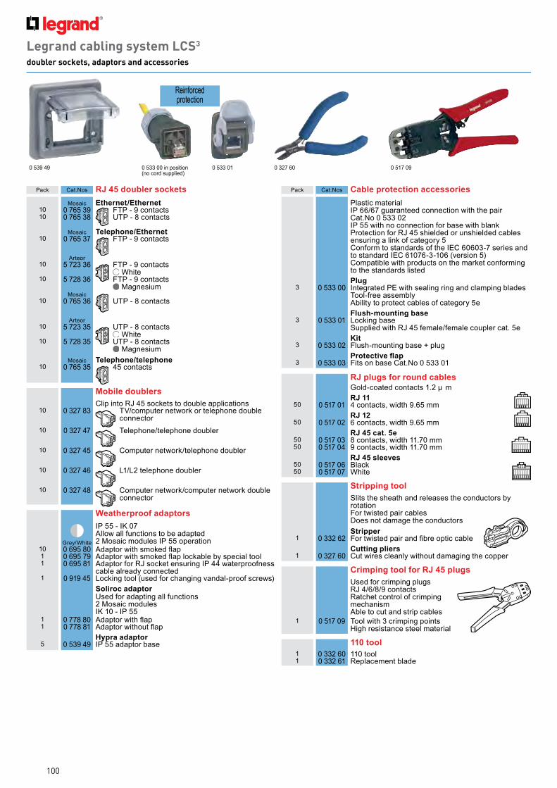
100
Legrand cabling system LCS3
doubler sockets, adaptors and accessories
Pack C at.N os Cable protection accessoriesPlastic material I P 66/67 g uaranteed connection with th e pair C at.N o 0 533 02 I P 55 with no connection for b ase with b lank Protection for RJ 4 5 sh ielded or unsh ielded cab les ensuring a link of categ ory 5 C onform to standards of th e I E C 60603- 7 series and to standard I E C 6107 6- 3- 106 ( version 5) C ompatib le with products on th e mark et conforming to th e standards listedPlug
3 0 533 00 I nteg rated PE with sealing ring and clamping b lades Tool- free assemb ly Ab ility to protect cab les of categ ory 5eFlush-mounting base
3 0 533 01 L ock ing b ase Supplied with RJ 4 5 female/female coupler cat. 5eKit
3 0 533 02 Flush - mounting b ase + plugrotecti e ap
3 0 533 03 Fits on b ase C at.N o 0 533 01
RJ plugs for round cablesG old- coated contacts 1.2 µ mRJ 11
50 0 517 01 4 contacts, width 9 .65 mmRJ 12
50 0 517 02 6 contacts, width 9 .65 mmRJ 45 cat. 5e
50 0 517 03 8 contacts, width 11.7 0 mm50 0 517 04 9 contacts, width 11.7 0 mm
RJ 45 sleeves50 0 517 06 B lack50 0 517 07 W h ite
Stripping toolSlits th e sh eath and releases th e conductors b y rotation For twisted pair cab les Does not damag e th e conductorsStripper
1 0 332 62 For twisted pair and fibre optic cableCutting pliers
1 0 327 60 C ut wires cleanly with out damag ing th e copper
Crimping tool for RJ 45 plugsUsed for crimping plug s RJ 4 /6/8 /9 contacts Ratch et control of crimping mech anismAb le to cut and strip cab les
1 0 517 09 Tool with 3 crimping points Hig h resistance steel material
110 tool1 0 332 60 110 tool1 0 332 61 Replacement b lade
Pack C at.N os RJ 45 doubler socketsMosaic Ethernet/Ethernet
10 0 7 65 39 FTP - 9 contacts10 0 7 65 38 UTP - 8 contacts
Mosaic Telephone/Ethernet10 0 7 65 37 FTP - 9 contacts
Arteor10 5 7 23 36 FTP - 9 contacts
W h ite10 5 7 28 36 FTP - 9 contacts
Mag nesiumMosaic
10 0 7 65 36 UTP - 8 contacts
Arteor10 5 7 23 35 UTP - 8 contacts
W h ite10 5 7 28 35 UTP - 8 contacts
Mag nesiumMosaic Telephone/telephone
10 0 7 65 35 4 5 contacts
Mobile doublersC lip into RJ 4 5 sock ets to doub le applications
10 0 327 8 3 TV /computer network or teleph one doub le connector
10 0 327 4 7 Teleph one/teleph one doub ler
10 0 327 4 5 C omputer network /teleph one doub ler
10 0 327 4 6 L 1/L 2 teleph one doub ler
10 0 327 4 8 C omputer network /computer network doub le connector
Weatherproof adaptors
G rey/ W h ite
I P 55 - I K 07 Allow all functions to b e adapted 2 Mosaic modules I P 55 operation
10 0 69 5 8 0 Adaptor with smoked flap1 0 69 5 7 9 Adaptor with smoked flap lockable by special tool1 0 69 5 8 1 Adaptor for RJ sock et ensuring I P 4 4 waterproofness
cab le already connected1 0 9 19 4 5 L ock ing tool ( used for ch ang ing vandal- proof screws)
Soliroc adaptorUsed for adapting all functions2 Mosaic modulesI K 10 - I P 55
1 0 7 7 8 8 0 Adaptor with flap1 0 7 7 8 8 1 Adaptor without flap
Hypra adaptor5 0 539 4 9 I P 55 adaptor b ase
0 517 090 533 01 0 327 600 539 4 9 0 533 00 in position( no cord supplied)
Reinforcedprotection

101
Legrand cabling system LCS3
data and telephone sockets, patch panels, cables
Pack C at.N os Telephone socketsRJ 11 and RJ 12 sockets
Mosaic Arteor
E q uipped with a modular J ack connector with 1/4 turn terminal for fast connection Tap- off possib le
10 0 7 8 7 30 5 7 23 00 W h ite - RJ 11, 4 contacts 1 module10 0 7 9 2 31 - Aluminium - RJ 11, 4 contacts -
1 module10 - 5 7 28 00 Mag nesium - RJ 11, 4 contacts -
1 module10 0 7 8 7 31 5 7 23 13 W h ite - RJ 11, 4 contacts -
2 modules10 - 5 7 28 13 Mag nesium - RJ 11, 4 contacts -
2 modules10 0 7 8 7 32 5 7 23 12 W h ite - RJ 12, 6 contacts -
2 modules10 - 5 7 28 12 Mag nesium - RJ 12, 6 contacts -
2 modulesISDN socketSelf- stripping 1/4 turn terminals for fast connection. Tap- off possib le
10 0 7 8 7 34 - W h ite - 8 contacts, 2.5 mm2 earth terminal
Single master - 2 modulesW ith I DC connectionC onform to B ritish Telecom
10 - 5 7 23 10 W h ite10 - 5 7 28 10 Mag nesium
Single secondary - 1 moduleW ith I DC connectionC onform to B ritish Telecom
5 - 5 7 23 01 W h ite5 - 5 7 28 01 Mag nesium
Pack C at.N os Patch panel telephone 50 ports 110 connect1 0 335 7 9 19 " panel - 1 U
Cables for telephone networks cat. 3PV C sleeve C olour wh ite C olour code TI A/E I AU/UTP - 50 pairs
1 0 328 9 1 L eng th 500 m Supplied on reelU/UTP - 100 pairs
1 0 328 8 8 L eng th 500 m Supplied on reel
Panels and units for incoming telephonePanels assembled - 1 UFitted with 4 L C S3 RJ 4 5 units of 12 ports with fast tool- free connection
1 0 335 31 3- 6/4 - 5 contacts for dig ital teleph one1 0 335 30 4 - 5/7 - 8 contacts for analog ue teleph one
Incoming telephone units for self-assembly panelsFitted with 12 L C S3 RJ 4 5 ports with q uick tool- free connection
2 0 335 33 3- 6/4 - 5 contacts for dig ital teleph one2 0 335 32 4 - 5/7 - 8 contacts for analog ue teleph one
0 335 7 95 7 23 13

102
Legrand cabling system LCS³ fibre optic19” optic drawers
0 321 62
0 321 00
0 321 7 2
0 321 210 321 330 321 15
N ew L C S3 system
Pack C at.N os Equipped 19" optic drawersMetal eq uipped 19 " optic drawers with 4 cab le inputs, supplied with fastening k it, 1 PE Ø 13.5 mm, coiling system and pig tail ductPanel and optic port mark ing on dedicated mark ing areasSlidingE nd of travel stop with 30° tiltingMaximum capacity either:- 24 ST and SC connectors- 4 8 L C connectorsDepth 220 mm, h eig h t 1 U
1 0 321 61 12 SC duplex multi-mode connectors for 24 fibres1 0 321 62 24 LC duplex multi-mode connectors for 48 fibres1 0 321 63 24 ST multi-mode connectors for 48 fibres1 0 321 64 12 SC duplex single-mode connectors for 24 fibres1 0 321 65 24 LC duplex single-mode connectors for 48 fibres1 0 321 66 12 SC APC duplex single-mode connectors for 24
fibres1 0 321 67 24 LC APC duplex single-mode connectors for 48
fibresRotatingDelivered with reversib le left or rig h t opening Maximum capacity, either:- 7 2 L C connectors- 36 SC connectorsDepth 260 mm, h eig h t 1 U
1 0 321 7 1 36 LC duplex multi-mode connectors for 72 fibres1 0 321 7 2 18 SC duplex multi-mode connectors for 36 fibres1 0 321 7 3 36 LC duplex single-mode connectors for 72 fibres1 0 321 7 4 18 SC duplex single-mode connectors for 36 fibres
19" modular optic drawersMetal modular 19 " optic drawers with 8 cab le inputs, supplied with fastening k it, 2 PE Ø 13.5 mm, coiling system and splice cassetteComplete with new generation Quick-Fix for automatic mounting ( no screws req uired) on th e risers of cab inets or enclosuresSupplied with numb ered lab elsE nd of travel stop with 30° tiltingMaximum capacity either:- 9 6 L C connectors - 4 8 SC connectors- 24 ST connectorsDepth 215 mm, h eig h t 1 USliding, equipped
1 0 321 02 12 SC duplex multi-mode connectors for 24 fibres1 0 321 04 24 LC duplex multi-mode connectors for 48 fibres1 0 321 06 12 SC duplex single-mode connectors for 24 fibres
liding to be e uipped with fibre optic bloc sIt can accept all fibre optic blocks 4 blocks maximum
1 0 321 00 E mpty drawer
Pack C at.N os Fibre optic blocksTh ey are clipped directly to th e optic drawer to b e equipped,Cat.No 0 321 00, or the fibre optic splice cassette, C at.N o 0 321 4 1
inglemode fibre optic bloc s 2 m1 0 321 17 ST block for 6 single-mode fibre optics1 0 321 10 SC duplex block for 6 single-mode fibre optics1 0 321 11 SC duplex high density block for 12 single-mode fibre
optics1 0 321 12 SC APC duplex block for 6 single-mode fibre optics1 0 321 13 LC duplex block for 6 single-mode fibre optics1 0 321 14 LC duplex block for 12 single-mode fibre optics1 0 321 15 LC duplex high density block for 24 single-mode fibre
optics1 0 321 16 LC APC duplex block for 12 single-mode fibre optics1 0 321 33 Sing le- mode 4 MTP1 feedth roug h adapter
ultimode fibre optic bloc s 2 and 2 m1 0 321 27 ST block for 6 multimode fibre optics1 0 321 20 SC duplex block for 6 multimode fibre optics1 0 321 21 SC duplex high density block for 12 multimode fibre
optics1 0 321 23 LC duplex block for 6 multimode fibre optics1 0 321 24 LC duplex block for 12 multimode fibre optics1 0 321 25 LC duplex high density block for 24 multimode fibre
optics1 0 321 34 Multimode 4 MTP1 feedth roug h adapter
opper bloc for fibre optic drawer1 0 321 32 I t clippes directly to th e optic drawer to b e eq uipped,
C at.N o 0 321 00 It gives the possibility of mixing fibre optic and copper
Accessories for optic drawer to be equippedAccessory for receipt of a fan-out
1 0 321 28 I t' s clipped at th e b ack of th e drawerI t enab les th e entry of preterminated C at.N osBlank
1 0 321 29 B lank b lockPigtail cassette
1 0 321 30 Capacity 24 fibre opticsCoiling kit
1 0 321 31 1 accessory
1: MTP is a reg istered trademark of US C onec L td

103
Legrand cabling system LCS³ fibre optic19" fibre optic drawers and mini-splicer
0 321 4 60 321 430 321 41
N ew L C S3 system
0 321 4 0 + 0 321 4 1 Panel 0 321 4 0 to b e eq uipped with 4 cassettes 0 321 4 3
Pack C at.N os Accessories for 19" panel to be equipped with cassettesRear cable management accessory
1 0 321 4 6 For installation on panels C at.N o 0 321 4 0ord management it guide support door
1 0 321 4 7 For installation on panel Cat.No 0 321 40 2 side cord manag ement and front door with integ rated marki ng to ensure correct front and side cord manag ement C ord support to b e installed on th e cassette to make side passag es easier
Smart splicerCompact and robust tool, excellent hand grip, easy to transport. Allows th e fusion and protection of pig tails, state report of insertion losses ( I L typical = 0, 1 dB ) b y insertion led control ( I L ) . USB port to download th e I L datas.C omposition:- 1 splicerDim: 95x132x71 mmW eig h t: 550 g rI P: 50- 1 precision cleaver- 1 adapter for different L C and SC standards- 1 lith ium b attery ( autonomy: 8 0 splice and protection cycles)- Power cord- 2 fiber holders - 900 µ m
1 0 322 00 1 splicer k it for pig tails1 0 322 02 Fib er h older repla 9 00 microns1 0 322 03 Fib er h older 250 microns1 0 322 04 1 C ord L C - L C APC1 0 322 05 1 C ord L C - L C1 0 322 06 1 C ord L C - SC APC1 0 322 07 1 C ord L C - SC1 0 322 08 1 Adaptater L C - L C1 0 322 09 1 Adaptater SC - SC1 0 322 7 6 Fib er stripper1 0 322 7 7 W ipes1 0 322 7 8 C leaning spray b ottle
Pack C at.N os Modular 19" panel to be equipped with cassettesTo be equipped with maximum 4 automatic extraction cassetteComplete with new generation Quick-Fix for automatic mounting ( no screws req uired) on th e risers of cab inets or enclosures Maximum capacity, either:- 4 8 SC connectors- 24 ST connectors- 9 6 L C connectors
1 0 321 4 0 Depth 19 0 mm, h eig h t 1 U
Optic drawer cassettesTh ey are installed directly in th e optic panel, C at.N o 0 321 4 0 Removab le cassette Extraction by simple pressure of the cassette, making installation and maintenance easierFibre optic splice cassette
1 0 321 4 1 It can accept all modular fibre optic blocksCopper cassette to be equipped
1 0 337 55 I t can accept 6 cat. 5e, cat. 6 and cat. 6A connectorsMTP1 preterminated cassette compatibleFront and rear extraction Hig h performance cassette, low insertion loss < 0.35 dB
1 0 321 4 2 Multimode OM4 cassette ( 50/125 µ m) 24 filaments LC OM4 Type A/C
1 0 321 4 3 Multimode OM4 cassette ( 50/125 µ m) 12 SC OM4 Type A/C
1 0 321 4 4 Sing le- mode OS2 cassette ( 9 /125 µ m) type OS2 24 L C OS2 Type A/C
1 0 321 4 5 Sing le- mode OS2 cassette ( 9 /125 µ m) 12 SC OS2 Type A/C Blanking cassette
1 0 337 57 Used to b lank th e panelAdapters
1 0 321 33 Sing le- mode 4 MTP1 adapter ( installation in cassette 0 321 4 1)
1 0 321 34 Multi- mode 4 MTP1 adapter ( installation in cassette 0 321 4 1)
1: MTP is a reg istered trademark of US C onec L td
0 322 00

104
Legrand cabling system LCS³ fibre opticpigtails, glue-on connectors and fan-out units
0 322 20 0 322 7 0
0 322 7 2
0 322 8 3 0 322 8 1 0 322 8 5
0 322 7 3 0 322 7 5
0 322 31
Legrand cabling system LCS³ fibre opticcase and quick-connect connectors
Pack C at.N os PigtailsThey can be used for on-site connection of the fibre optic cable quick, reliable and performing: - OM2/OM3/OM4 I L Typical/Master = 0.15 db - OS2 I L Typical/Master = 0.18 db C ompatib le with all th e fusion splicers availab le on th e marke t
2 m 2 C onnectors
10 0 322 10 SC 1 m L SZ H10 0 322 11 L C 1 m L SZ H10 0 322 12 ST 1 m L SZ H10 0 322 13 SC 2 m L SZ H10 0 322 14 L C 2 m L SZ H10 0 322 15 ST 2 m L SZ H
2 m C onnectors
0 322 20 SC 1 m L SZ H10 0 322 21 L C 1 m L SZ H10 0 322 22 ST 1 m L SZ H10 0 322 23 SC 2 m L SZ H10 0 322 24 L C 2 m L SZ H
2 m C onnectors
10 0 322 30 SC 1 m L SZ H10 0 322 31 L C 1 m L SZ H10 0 322 32 ST 1 m L SZ H10 0 322 33 SC 2 m L SZ H10 0 322 34 L C 2 m L SZ H
2 m 2 or compatibleC onnectors
10 0 322 4 0 SC - APC OS2 1 m L SZ H10 0 322 4 1 SC - UPC OS2 1 m L SZ H10 0 322 4 2 L C - APC OS2 1 m L SZ H10 0 322 4 3 L C - UPC OS2 1 m L SZ H10 0 322 4 4 ST- UPC OS2 1 m L SZ H10 0 322 4 5 SC - APC OS2 2 m L SZ H10 0 322 4 6 SC - UPC OS2 2 m L SZ H10 0 322 4 7 L C - UPC OS2 2 m L SZ H10 0 322 4 8 L C - APC OS2 2 m L SZ H10 0 322 4 9 ST- UPC OS2 2 m L SZ H
Set of 12 LC pigtails1 0 326 24 OS2 12 pig tails L C - UPC1 0 326 26 OM3 12 pig tails L C - PC1 0 326 7 1 OM4 12 pig tails L C - PC
Pigtail sleeves1 0 327 4 4 4 0 mm - b ag of 50 sh eath s
Glue-on connectors 50/125 and 62.5/125 µ mSupplied with 9 00 µ m sleeve C eramic ferrule connector Typical attenuation: 0.3 dBC onnectors
10 0 331 27 ST10 0 331 4 7 SC10 0 331 00 L C
Fan-out unitsIt allows a 900 µm fibre optic gain 250 µm diameter fibre optics accepted
1 0 330 4 8 6 fibre optic fan-out unit1 0 330 4 9 12 fibre optic fan-out unit
Pack C at.N os Tool case for the preparation of the fibre optic for quick-connect connectors
1 0 322 7 0 I t contains th e tools req uired for th e preparation of th e fibre optic cable, for the completion of a first test to confirm the correct connection of the fibre optic to the connector, and th e accessories for easy connection in all situations C onsisting of: - Precision cleaver - K evlar stripping and cutting tool - V isual defect detector - I nstallation details and video - Accessories ( cleaners, marke r, trash can...)
Q uick-connect connectorsPreparation completed using th e case, C at.N o 0 322 7 0 E asy to connect, reliab le and reusab le up to 5 times They enable the locking of the fibre optic inside the connector A L E D is used to test th e connection N o g lue or polish ing req uired They can be installed on 900 µm fibre optics For 250 µm fibre optic use dedicated tubes, delivered with the connector typical IL multimode OM3/OM4 0.1 db , sing le mode OS2 = 0.2 db ( PC ) and 0.3 db ( APC )OM3/OM4 multimode connectorsSet of 12 connectors
1 0 322 7 1 L C PC 50/125 µ m, 9 00/250 µ m1 0 322 7 2 SC PC 50/125 µ m, 9 00/250 µ m
OS2 single-mode connectorsSet of 12 connectors
1 0 322 7 3 L C UPC 9 /125 µ m, 9 00/250 µ m1 0 322 7 4 SC UPC 9 /125 µ m, 9 00/250 µ m1 0 322 7 5 SC APC 9 /125 µ m, 9 00/250 µ m
Precision cleaver for the update of the case kit Cat.No 0 326 90
1 0 322 8 0 It s used in con unction with the kit of the case Cat.No 0 326 90, to cut the fibre optic with precision, and fit the quick-connect connectors, Cat.No 0 322 71 to 0 322 7 5
Fibre optic cleaning accessories1 0 322 8 3 Ferrule cleaner MPO/MTP1
1 0 322 8 1 Ferrule cleaner L C ( PC /APC )1 0 322 8 2 Ferrule cleaner SC ( PC /APC )1 0 322 8 4 L C replacement cartridg e1 0 322 8 5 L C replacement cartridg e
1: MTP is a reg istered trademark of US C onec L td

105
Pack C at.N os odular fibre optic drawers ultra high density to be equipped with cassettesFixed and modular chassis for the reception of the drawersFibre optic drawers with front facing cord managementMaximum capacity 4 U (up to 48 cassette)- 57 6 L C connectorsMaximum capacity 2 U (up to 24 cassette)- 28 8 L C connectorsMaximum capacity 1 U (up to 12 cassette) - 14 4 L C connectors
1 0 321 50 1 U1 0 321 52 2 U1 0 321 53 4 U1 0 321 51 UHD Panel to b e eq uipped cassette with out rear
manag ement 1 U
V ery high density cassettesThey are clipped directly to the fibre optic drawers, C at.N os 0 321 50/51/52/53Sliding cassette for th e ab ove ch assis Front or rear cassette extractionMTP1 h ig h performance cassette L ow insertion loss < 0, 35 dB A/C polarity
ultimode cassette 2 mFor OM4 type 50/125 m multimode installations
1 0 321 54 MPO cassette 12 L C OM4 Type A/C
2 cassette 2 mFor OS2 type 9/125 m multimode installations
1 0 321 55 MPO cassette 12 L C OS2 Type A/C
MTP1 adapters compatibleThey are clipped directly to the fibre optic drawers, C at.N os 0 321 50/51/52/53
1 0 321 56 Multimode 4 MTP1 adapter1 0 321 57 Sing le- mode 4 MTP1 adapter
LC adapterIt s clipped directly to the fibre optic drawers, C at.N os 0 321 50/51/52/53
1 0 321 58 Adapter 12 L C multimode
Pack C at.N os Modular 19" panel to be equipped with cassettesTo be equipped with a maximum of 4 automatic extraction cassettes Complete with new generation Quick-Fix for automatic mounting ( no screws req uired) on th e risers of cab inets or enclosures Maximum capacity, either: - 4 8 SC connectors - 24 ST connectors - 9 6 L C connectors
1 0 321 4 0 Depth 19 0 mm, h eig h t 1 U
High density MTP1 cassette compatibleTh ey are installed in th e modular panels, C at.N o 0 321 4 0 Sliding cassette that can be extracted by simple pressure, mak ing installation and maintenance easier Front and rear extraction Hig h performance MTP1 cassette, low insertion loss < 0.35 dB , A/C polarityFibre optic splice cassette
1 0 321 4 1 It can accept all modular fibre optic blocksCopper cassette to be equipped
1 0 337 55 I t can accept 6 cat. 5e, cat. 6 and cat. 6A connectors ultimode cassettes 2 m
1 0 321 4 2 MTP1 cassette ( MPO compatib le) 24 L C OM4 Type A/C
1 0 321 4 3 MTP1 cassette ( MPO compatib le) 12 SC OM4 Type A/C
ingle mode 2 cassettes 2 mOS2 type
1 0 321 4 4 MTP1 cassette ( MPO compatib le) 24 L C OS2 Type A/C
1 0 321 4 5 MTP1 cassette ( MPO compatib le) 12 SC OS2 Type A/CBlanking cassette
1 0 337 57 Used to b lank th e panel
MTP1 adapters I t' s installed in splice cassettes, C at.N o 0 321 4 1 I t enab les MTP1/MTP1 feedth roug h
1 0 321 33 Sing le- mode 4 MTP1 adapter1 0 321 34 Multimode 4 MTP1 adapter
Accessories for 19" panel to be equipped with cassetteRear cable management accessory
1 0 321 4 6 For installation on panels C at.N o 0 321 4 0ord management it guide support door
1 0 321 4 7 For installation on panel Cat.No 0 321 40 2 side cord manag ement and front door with integ rated mark ing to ensure correct front and side cord manag ement C ord support to b e installed on th e cassette to mak e side passag es easier
Legrand cabling system LCS³ fibre optic19" high density and very high density fibre optic drawers
0 321 55
0 321 330 321 4 0
0 321 560 321 50
0 321 4 30 321 4 1
1: MTP is a reg istered trademark of US C onec L td

106
Legrand cabling system LCS³fibre optic preterminated solution
Legrand cabling system LCS³ fibre opticcables
0 324 4 1
Tech nical ch aracteristics see e-catalogue
L SOH sh eath ( exce pt C at.N os 0 325 4 6 /4 7 )C olour code FOTAGC ompliance with th e E N 5017 3- 2, I SO I E C 118 01 standardPacki ng on drum Tig h t structure: " easy strip"
0 326 66
Pack C at.N os multimode fibre optic cables (50/125 µ m)
L oose tub e
Tig h t structure 9 00 µ m
" B end insensitive" For multimode installations 50/125 µ m, type OM 4 Aq ua sh eath s Suitab le for 10 G ig a E th ernet networks
2000 0 325 4 3 I ndoor/outdoor ( g lass strands) 4 fibres - 2000 m
2000 0 325 4 4 I ndoor/outdoor ( g lass strands) 8 fibres - 2000 m
2000 0 325 4 5 I ndoor/outdoor ( g lass strands) 12 fibres - 2000 m
2000 0 325 4 6 Outdoor, corrug ated steel tape 4 fibres - 2000 m
2000 0 325 4 7 Outdoor, corrug ated steel tape 8 fibres - 2000 m
2000 0 325 4 8 Outdoor, corrug ated steel tape 12 fibres - 2000 m
500 0 326 65 I ndoor/outdoor ( g lass strands) 6 fibres - 500 m
1000 0 326 66 I ndoor/outdoor ( g lass strands) 6 fibres - 1000 m
1000 0 326 67 I ndoor/outdoor ( g lass strands) 12 fibres - 1000 m
1000
1000
1000
500
0 326 68
0 326 67
0 326 66
0 326 65
I ndoor/outdoor ( g lass strands) 24 fibres - 1000 mCable fibre OM4 12f t-buffer int/ext m-mode aq ua ( 1000m)Cable fibre OM4 6f t-buffer int/ext m-mode aq ua ( 1000m)Cable fibre OM4 6f t-buffer int/ext m-mode aq ua ( 500m)
Pack C at.N os igh density preterminated fibre optic lin sDelivered on cardb oard drumsC onnection of h ig h density drawer cassetteL ow density micro- cab leSh eath s in L SZ H, colour aq ua ( OM3) and yellow ( OS2)Supplied with test reports and unwinderFan- out - Fan- out: spark g ap in anodised aluminium for optimum resistanceL ow connector insertion loss L C < 0, 15 dB /connectorMTP1 - MTP1 : low connector insertion loss MTP1 < 0.35 dB /connectorOther configurations on request
icro cables an out an outMicro cab les with spark g ap, output 2 mm
Desig nation L eng th ( m)1 0 324 01 6 L C Duplex - 6 L C Duplex 101 0 324 02 6 L C Duplex - 6 L C Duplex 201 0 324 03 6 L C Duplex - 6 L C Duplex 301 0 324 04 6 L C Duplex - 6 L C Duplex 4 01 0 324 05 6 L C Duplex - 6 L C Duplex 501 0 324 11 12 L C Duplex - 12 L C Duplex 101 0 324 12 12 L C Duplex - 12 L C Duplex 201 0 324 13 12 L C Duplex - 12 L C Duplex 301 0 324 14 12 L C Duplex - 12 L C Duplex 4 01 0 324 15 12 L C Duplex - 12 L C Duplex 50
icro cables 2 an out an outMicro cab les with spark g ap, output 2 mm
Desig nation L eng th ( m)1 0 324 21 6 L C Duplex - 6 L C Duplex 101 0 324 22 6 L C Duplex - 6 L C Duplex 201 0 324 23 6 L C Duplex - 6 L C Duplex 301 0 324 24 6 L C Duplex - 6 L C Duplex 4 01 0 324 25 6 L C Duplex - 6 L C Duplex 501 0 324 31 12 L C Duplex - 12 L C Duplex 101 0 324 32 12 L C Duplex - 12 L C Duplex 201 0 324 33 12 L C Duplex - 12 L C Duplex 301 0 324 34 12 L C Duplex - 12 L C Duplex 4 01 0 324 35 12 L C Duplex - 12 L C Duplex 50
icro cables T 1
Desig nation L eng th ( m)1 0 324 4 1 12 fibre optics - MTP1 - MTP1 101 0 324 4 2 12 fibre optics - MTP1 - MTP1 201 0 324 4 3 12 fibre optics - MTP1 - MTP1 301 0 324 4 4 12 fibre optics - MTP1 - MTP1 4 01 0 324 4 5 12 fibre optics - MTP1 - MTP1 50
icro cables 2 T 1
Desig nation L eng th ( m)1 0 324 51 12 fibre optics - MTP1 - MTP1 101 0 324 52 12 fibre optics - MTP1 - MTP1 201 0 324 53 12 fibre optics - MTP1 - MTP1 301 0 324 54 12 fibre optics - MTP1 - MTP1 4 01 0 324 55 12 fibre optics - MTP1 - MTP1 50
1: MTP is a reg istered trademark of US C onec L td

107
Legrand cabling system LCS³ fibre opticcables (continued)
Tech nical ch aracteristics see e-catalogue
L SOH sh eath ( exce pt C at.N os 0 325 13, 0 325 15, 0 325 23, 0 325 24 , 0 325 25, 0 325 4 0, 0 325 4 1 and 0 325 4 2)C olour code: FOTAGC ompliance with th e E N 5017 3- 2, I SO I E C 118 01 standardPacki ng on drum ( 2000 m) Tig h t structure: " easy strip"
0 325 30
0 325 33
Pack C at.N os 2 single mode fibre optic cables (9/125 µ m) - compatible
L oose tub e
Tig h t structure 9 00 µ m
For sing le- mode installations 9 /125 µ m, type OS 2 Y ellow or b lack sh eath s for outdoor, rodent g uard...
1000 032534 C ab le 12f OS2 t- b uffer UV lszh in/out s- mode yellow ( 1000m)
1000 032535 C ab le 24 f OS2 t- b uffer UV lszh in/out s- mode yellow ( 1000m)
1000 032533 C ab le 6f OS2 t- b uffer UV lszh in/out s- mode yellow ( 1000m)
2000 032514 Cable fibre OS1 12f l-tube int/out s-mode yellow ( 2000m)
2000 032512 Cable fibre OS1 6f l-tube inn/out s-mode yellow ( 2000m)
1000 032539 C ab le 6f OS2 loose tub e pe/ny s- mode b lue ( 1000m)
1000 03254 1 C ab le 24 f OS2 loose tub e pe/ny s- mode b lue( 1000m)
1000 03254 0 C ab le 12f OS2 loose tub e pe/ny s- mode b lue( 1000m)
2000 032550 Cable fibre OS1 12f t-buffer inn/out s-mode yellow ( 2000m)
Pack C at.N os multimode fibre optic cables (50/125 µ m)
L oose tub e
Tig h t structure 9 00 µ m
" B end insensitive" For multimode installations 50/125 µ m, type OM 3 Aq ua sh eath s Suitab le for 10 G ig a E th ernet networks
1000 032537 C ab le 12f OM3 loose tub e pe/ny m- mode b lue ( 1000m)
1000 032538 C ab le 24 f OM3 loose tub e pe/ny m- mode b lue ( 1000m)
2000 032552 Cable fibre OM3 24f t-buffer inn/out m-mode aq ua ( 2000m)
1000 032531 C ab le 12f OM3 t- b uffer UV L SZ H in/out m- mode aq ua ( 1000m)
1000 032532 C ab le 24 f OM3 t- b uffer UV L SZ H in/out m- mode aq ua ( 1000m)
1000 032536 C ab le 6f OM3 loose tub e pe/ny m- mode b lue ( 1000m)
1000 032530 C ab le 6f OM3 t- b uffer UV L SZ H in/out m- mode aq ua ( 1000m)

108
Pack C at.N os multimode fibre optic cords 2 mSuitab le for 10 G ig a E th ernet networks Optic losses max/ Master: 0.25 dB For multimode installations 50/125 µ m, type OM 3 Aq ua sh eath s
duple cords3 0 326 09 L eng th : 1 m3 0 326 10 L eng th : 2 m3 0 326 11 L eng th : 3 m
duple cords3 0 326 12 L eng th : 1 m3 0 326 13 L eng th : 2 m3 0 326 14 L eng th : 3 m
duple cords3 0 326 15 L eng th : 1 m3 0 326 16 L eng th : 2 m3 0 326 17 L eng th : 3 m
2 multimode fibre optic cords 2 mOptic losses max/ Master: 0.25 dB For multimode installations 50/125 µ m, type OM2 Orang e sh eath s
T T duple cords3 0 330 8 0 L eng th : 1 m3 0 330 8 1 L eng th : 2 m3 0 330 8 2 L eng th : 3 m
duple cords3 0 330 69 L eng th : 1 m3 0 330 7 0 L eng th : 2 m3 0 330 7 1 L eng th : 3 m
T duple cords3 0 330 7 2 L eng th : 2 m3 0 330 7 3 L eng th : 3 m
duple cords3 0 330 61 L eng th : 2 m
duple cords3 0 330 7 5 L eng th : 1 m3 0 330 63 L eng th : 2 m3 0 330 7 6 L eng th : 3 m
T duple cords3 0 330 65 L eng th : 2 m
ibre optic feedthrough soc etsE q uipped with 2 inputs / 2 outputs duplex feedth roug h Enable the connection of two fibre optics (fitted with their connectors) Supplied with protection caps E q uipped with a clear nameplate h older 2 modules2 T fibre optic feedthrough soc etB ayonet mount ( STI I compatib le)
1 0 7 8 6 16 W h ite
2 fibre optic feedthrough soc et" Push - pull" connection
1 0 7 8 6 17 W h ite
2 fibre optic feedthrough soc et" Push - pull" connection
1 0 7 8 6 18 W h ite
Legrand cabling system LCS³ fibre opticpatch cords
0 326 07 0 326 13
Fitted with ceramic ferrule connectors on each end I ndividually packe d and tested ( report supplied) Z ipcord L SZ H sh eath
Pack C at.N os 2 single mode optical cordsOptic losses max/ Master: 0.25 dB For sing le- mode installations 9 /125 µ m, type OS 1/OS 2 Y ellow sh eath s
duple cords3 0 326 00 L eng th : 1 m3 0 326 01 L eng th : 2 m3 0 326 02 L eng th : 3 m
duple cords3 0 326 03 L eng th : 1 m3 0 326 04 L eng th : 2 m3 0 326 05 L eng th : 3 m
duple cords3 0 326 28 L eng th : 0.5 m3 0 326 06 L eng th : 1 m3 0 326 07 L eng th : 2 m3 0 326 08 L eng th : 3 m3 0 326 29 L eng th : 5 m
niboot duple cordsReversib le polarity
3 0 326 8 6 L eng th : 1 m3 0 326 8 7 L eng th : 2 m3 0 326 8 8 L eng th : 3 m3 0 326 8 9 L eng th : 5 m3 0 326 9 2 L eng th : 10 m
multimode fibre optic cords 2 mSuitab le for 10 G ig a E th ernet networksOptic losses max/ Master: 0.15 dBfor multimode installations 50/125 m, type OM 4Aq ua sh eath s
duple cords3 0 326 30 L eng th : 1 m3 0 326 31 L eng th : 2 m3 0 326 32 L eng th : 3 m
duple cords3 0 326 33 L eng th : 0.5 m3 0 326 34 L eng th : 1 m3 0 326 35 L eng th : 2 m3 0 326 36 L eng th : 3 m3 0 326 37 L eng th : 5 m
niboot duple cordsReversib le polarity
3 0 326 9 5 L eng th : 1 m3 0 326 9 6 L eng th : 2 m3 0 326 9 7 L eng th : 3 m3 0 326 9 8 L eng th : 5 m3 0 326 9 9 L eng th : 10 m

109
Legrand cabling system LCS³ Enclosuresserver cabinets and cable entries
4 4 60 4 5 4 4 60 4 64 4 60 00
er er cabinetsLegrand offers a wide range of server and network cabinets, with flexibility, sustainability and service as the keywords. The server and network cabinets are widely applicab le and modular in structure.
pecifications- C olour: RAL 9 011 ( b lack)- Frame: Aluminium, demountab le - L oad capacity: 1500 kg ( static) - Front door: 80 perforated front door. Door is fitted with a Fix-easy swivel handle with a snap-in blind plug for profile-cylinder- Rear door: 80 perforated double rear doors. Door is fitted with a Fix-easy swivel handle with a snap-in blind plug for profile-cylinder- Roof: 3 or 4 cut outs with 2 or 3 b lind plates and 1 cab le entry b rush Depending on th e frame size- Interior: The cabinet is equipped with 4 x 19"-profiles including height (U) indicationTh e distance to th e cab inet front is set to 8 0 mm, th e pitch to 7 4 0 mm - C ab le Manag ement: Th e cab inet is eq uipped with two cab le trays for cab le manag ement. Special features include toolless mount ke y h oles for mounting vertical PDU s and fixation points to mount Plastic Cable Rings (4 460 57)- Accessories: Th e cab inets are supplied with 20 cag e nuts and screws- Server cab inets are delivered excl uding side panels
er er cabinets with air ow managementLegrand can provide server cabinets that are 600 or 800 mm wide with an airflow management package. These packages keep the loss of air to a minimum, which improves energy efficiency. The rest of the specifications are the same as the standard server cabinets.
Pack C at.N os ser er cabinets
C apacity W idth ( mm)
Depth ( mm)
1 4 4 60 00 4 2 U 600 10001 4 4 60 01 4 2 U 600 11001 4 4 60 02 4 2 U 600 12001 4 4 60 03 4 2 U 8 00 10001 4 4 60 04 4 2 U 8 00 11001 4 4 60 05 4 2 U 8 00 12001 4 4 60 06 4 6 U 600 10001 4 4 60 07 4 6 U 600 11001 4 4 60 08 4 6 U 600 12001 4 4 60 09 4 6 U 8 00 10001 4 4 60 10 4 6 U 8 00 11001 4 4 60 11 4 6 U 8 00 1200
ser er cabinets with air ow management
C apacity W idth ( mm)
Depth ( mm)
1 4 4 60 12 4 2 U 600 10001 4 4 60 13 4 2 U 600 11001 4 4 60 14 4 2 U 600 12001 4 4 60 15 4 2 U 8 00 10001 4 4 60 16 4 2 U 8 00 11001 4 4 60 17 4 2 U 8 00 12001 4 4 60 18 4 6 U 600 10001 4 4 60 19 4 6 U 600 11001 4 4 60 20 4 6 U 600 12001 4 4 60 21 4 6 U 8 00 10001 4 4 60 22 4 6 U 8 00 11001 4 4 60 23 4 6 U 8 00 1200
side panels for ser er cabinet set of 2 including plinths
C apacity W idth ( mm)
Depth ( mm)
1 4 4 60 24 4 2 U - 10001 4 4 60 25 4 2 U - 11001 4 4 60 26 4 2 U - 12001 4 4 60 27 4 6 U - 10001 4 4 60 28 4 6 U - 11001 4 4 60 29 4 6 U - 1200
Pack C at.N os latpac ser er cabinets including side panelsFlatpack cabinets have the same configuration as 4 4 60 00 - 4 4 60 11 respectively
C apacity W idth ( mm)
Depth ( mm)
1 4 4 60 30 4 2 U 600 10001 4 4 60 31 4 2 U 600 11001 4 4 60 32 4 2 U 600 12001 4 4 60 33 4 2 U 8 00 10001 4 4 60 34 4 2 U 8 00 11001 4 4 60 35 4 2 U 8 00 12001 4 4 60 36 4 6 U 600 10001 4 4 60 37 4 6 U 600 11001 4 4 60 38 4 6 U 600 12001 4 4 60 39 4 6 U 8 00 10001 4 4 60 4 0 4 6 U 8 00 11001 4 4 60 4 1 4 6 U 8 00 1200
able entry brush roofnsert modulesThe roof and/or floor plate of the cabinet have cut-aways that can be filled using various inserts. Depending on your situation, you can ch oose b etween a b lank cover plate or cab le entry b rush es
Max. cross- section
1 4 4 60 4 5 C ab le entry b rush es ( set) 4 05 x 115 mm
able entry blindplate roofnsert modules
The roof and/or floor plate of the cab inet h ave cut-aways that can be filled using various inserts. Depending on your situation, you can ch oose b etween a b lank cover plate or cab le entry b rush es
Max. cross- section
1 4 4 60 4 6 C overing plate RAL 9 011 153 x 4 27 mm

110
4 4 60 4 7 4 4 60 574 4 60 574 4 60 556 4 66 69 4 4 60 56
Legrand cabling system LCS³ Enclosurescable clips
4 4 60 7 5
Pack C at.N os ertical cable clipThis cable clip is used for finishing the assembly of cable bundles. The cable clip can be fitted to the 19" profiles
1 6 4 66 68 W idth : 4 5 mmDepth : 7 4 mmDelivery consists of: including assemb ly materials
ori ontal cable clipThis cable clip is used for finishing the assembly of cable bundles. The cable clip can be fitted to the 19" profiles
1 6 4 66 69 W idth : 4 0 mmDepth : 8 6 mmDelivery consists of: including assemb ly materials
able ducting front to bac slidingA telescopic cab le duct can b e used for g uiding cab les from th e front to th e b ack. Th e ducting can be attached to the side of the 19" profile. Cable entry foam can b e used tog eth er with side sealing plates to optimise the airflow.Th e cab le ducting can b e adj usted from 550 to 8 00 mmC ab le duct material: Sh eet metalFinish : G alvanisedC ab le g uide material: Plastic ( noryl; h alog en- free)C olour: B lue
1 4 4 60 55 V ariab le depth : 550 - 8 00 mmDelivery consists of: Cable duct including fitting materials
ounting brac et for the cable cleat cable cleatThe cable cleats are used to make cabling as efficient as possib le. Positioning th e cab le cleats along side the 19" profile allows the cables to be guided in an optimum fash ion Th e mounting b racke ts can b e attached to the 19" profile at any height
1 4 4 60 56 Material: SteelFinish ing : Powder coatedUnit: 1 UMounting b rack et ( 4 x ) for th e cab le cleat + 4 x cab le cleatW h at’ s in th e b ox : 4 x 1 U mounting b rack ets and 4 x cab le cleats with mounting materials
Transport caster remo ible set of 1 4 4 60 4 7 C asters provide you th e option of moving your rack
more often, more q uickl y and more easily. Th e casters are demountab le, wh ich means th ey can b e removed or placed later on.
Pack C at.N os lastic cable clipTh e plastic cab le clip is an ‘ eye’ wh ich can b e used for cab le manag ement. I t can b e attach ed with out tools to th e standard cab le trunki ngSet of 10
1 4 4 60 57 Material: PolyamideFire class: UL 9 4 - V 0W idth : 4 0 mmDepth : 7 8 mm
loor fi ing setThe floor fixing set will secure the frame to several floor types. If a computer floor is being used, we recommend a direct attachment to a lower floor, this is possib le b y using a leng th of stud. Th e stud is not included in th is set.Sockl e h eig h t ( mm)
1 4 4 60 7 6 1001 4 4 60 7 5 25
What s in the box: 2 -profiles with integrated nuts, including mounting material
1
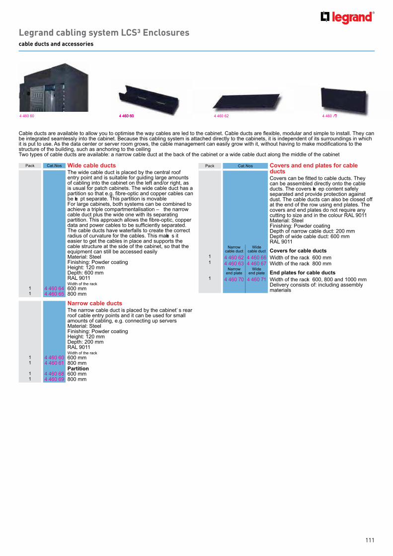
111
Legrand cabling system LCS³ Enclosurescable ducts and accessories
4 4 60 60 4 4 60 604 4 60 60
Pack C at.N os o ers and end plates for cable ductsCovers can be fitted to cable ducts. They can b e assemb led directly onto th e cab le ducts. Th e covers ke ep content safely separated and provide protection ag ainst dust. Th e cab le ducts can also b e closed off at th e end of th e row using end plates. Th e covers and end plates do not req uire any cutting to size and in th e colour RAL 9 011Material: SteelFinish ing : Powder coatingDepth of narrow cab le duct: 200 mmDepth of wide cab le duct: 600 mmRAL 9 011
N arrow cab le duct
W ide cab le duct o ers for cable ducts
1 4 4 60 62 4 4 60 66 W idth of th e rack: 600 mm1 4 4 60 63 4 4 60 67 W idth of th e rack: 8 00 mm
N arrow end plate
W ide end plate nd plates for cable ducts
1 4 4 60 7 0 4 4 60 7 1 W idth of th e rack: 600, 8 00 and 1000 mm Delivery consists of: including assemb ly materials
Cable ducts are available to allow you to optimise the way cables are led to the cabinet. Cable ducts are flexible, modular and simple to install. They can b e integ rated seamlessly into th e cab inet. B ecause th is cab ling system is attach ed directly to th e cab inets, it is independent of its surrounding s in wh ich it is put to use. As the data center or server room grows, the cable management can easily grow with it, without having to make modifications to the structure of th e b uilding , such as anch oring to th e ceiling Two types of cab le ducts are availab le: a narrow cab le duct at th e b ack of th e cab inet or a wide cab le duct along th e middle of th e cab inet
Pack C at.N os ide cable ductsTh e wide cab le duct is placed b y th e central roof entry point and is suitab le for g uiding larg e amounts of cab ling into th e cab inet on th e left and/or rig h t, as is usual for patch cab inets. Th e wide cab le duct h as a partition so that e.g. fibre-optic and copper cables can b e ke pt separate. Th is partition is movab leFor larg e cab inets, b oth systems can b e comb ined to ach ieve a triple compartmentalisation – th e narrow cab le duct plus th e wide one with its separating partition. This approach allows the fibre-optic, copper data and power cables to be sufficiently separated. Th e cab le ducts h ave waterfalls to create th e correct radius of curvature for th e cab les. Th is make s it easier to g et th e cab les in place and supports th e cab le structure at th e side of th e cab inet, so th at th e eq uipment can still b e accessed easilyMaterial: SteelFinish ing : Powder coatingHeig h t: 120 mmDepth : 600 mm RAL 9 011W idth of th e rack
1 4 4 60 64 600 mm1 4 4 60 65 8 00 mm
arrow cable ductsTh e narrow cab le duct is placed b y th e cab inet’ s rear roof cab le entry points and it can b e used for small amounts of cab ling , e.g . connecting up serversMaterial: SteelFinish ing : Powder coatingHeig h t: 120 mmDepth : 200 mm RAL 9 011W idth of th e rack
1 4 4 60 60 600 mm1 4 4 60 61 8 00 mm
artition1 4 4 60 68 600 mm1 4 4 60 69 8 00 mm
4 4 60 7 04 4 60 62 4 4 60 7 0

112
Legrand cabling system LCS³ Enclosurescable bridges and connecting sets
4 4 60 4 84 4 60 7 2 4 4 60 7 3
Pack C at.N os able bridgesW h ere a h ot or cold corridor h as to b e crossed, a cab le b ridg e can b e used. Th e cab le b ridg e is suitab le for a wide or narrow cab le duct. I t can also b e comb ined with aisle containment. Th e b ridg es use a sliding system so th at th e distance b etween th e cab le ducts can b e b ridg ed at any spot with out any sawing b eing necessary. Th e cab le duct can b e installed at various distances along th e depth of th e corridor. I t can b e used for instance to save on th e numb er of b ranch es in th e main supply or for intra- connectivity with in th e aisle containment. Y ou can ch oose to use several b ridg es depending on th e capacity req uired, or to ke ep various cab les separateMaterial: SteelFinish ing : Powder coatingHeig h t: 120 mm. W idth : 150 mmRAL 9 011
1 4 4 60 7 2 Usab le leng th : 9 9 0 to 17 50 mm Delivery consists of: including assemb ly materials
o ers for cable bridgesCovers can be fitted to the cable bridges. They are assemb led directly onto th e cab le b ridg es. Th e covers ke ep content safely separated and provide protection ag ainst dust. I t is possib le to h ave th e covers overlap so th at multiple covers can b e used to ensure proper coverag e of th e cab le b ridg eMaterial: SteelFinish ing : Powder coatingC apacity: 150 mm RAL 9 011
1 4 4 60 7 3 Usab le leng th : 1030 mmDelivery consists of: including assemb ly materials
Pack C at.N os onnecting setsC onnecting sets are needed to connect cab inets tog eth er. V arious comb inations are availab le of b oth internal connector tub es and ext ernal connector plates. Th e ext ernal connector plates can b e screwed onto th e outsides of th e structural uprig h ts and are invisib le wh en th e door is closed. Make at least 2 connections in th e front and b ack planes. Y ou need 2 sets for 25U or moreSet of internal and ext ernal rack connectorsMaterial: SteelFinish ing : Powder coatingC apacity: 150 mm RAL 9 011
1 4 4 60 4 8 E xt ernal connecting set of 6 pieces Delivery consists of: including fastening materials
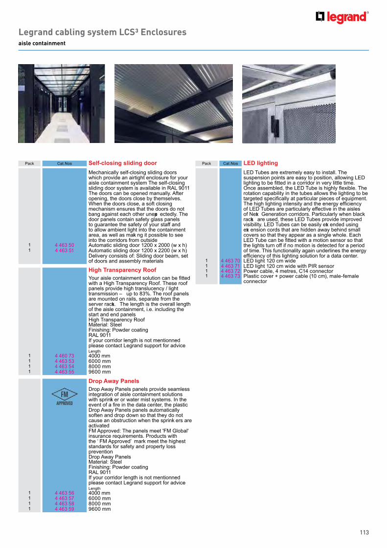
113
Legrand cabling system LCS³ Enclosuresaisle containment
Pack C at.N os elf closing sliding doorMech anically self- closing sliding doors wh ich provide an airtig h t enclosure for your aisle containment system Th e self- closing sliding door system is availab le in RAL 9 011 Th e doors can b e opened manually. After opening , th e doors close b y th emselves. W h en th e doors close, a soft closing mech anism ensures th at th e doors do not b ang ag ainst each oth er unexp ectedly. Th e door panels contain safety g lass panels to g uarantee th e safety of your staff and to allow amb ient lig h t into th e containment area, as well as maki ng it possib le to see into th e corridors from outside
1 4 4 63 50 Automatic sliding door 1200 x 2000 ( w x h )1 4 4 63 51 Automatic sliding door 1200 x 2200 ( w x h )
Delivery consists of: Sliding door b eam, set of doors and assemb ly materials
igh Transparency oofour aisle containment solution can be fitted
with a Hig h Transparency Roof. Th ese roof panels provide h ig h translucency / lig h t transmission – up to 8 3% . Th e roof panels are mounted on rails, separate from th e server racks. Th e leng th is th e overall leng th of th e aisle containment, i.e. including th e start and end panelsHig h Transparency Roof Material: SteelFinish ing : Powder coatingRAL 9 011I f your corridor leng th is not mentionned please contact L eg rand support for adviceL eng th
1 4 4 60 7 3 4 000 mm1 4 4 63 53 6000 mm1 4 4 63 54 8 000 mm1 4 4 63 55 9 600 mm
rop way anelsDrop Away Panels panels provide seamless integ ration of aisle containment solutions with sprinkl er or water mist systems. I n th e event of a fire in the data center, the plastic Drop Away Panels panels automatically soften and drop down so th at th ey do not cause an ob struction wh en th e sprinkl ers are activatedFM Approved: Th e panels meet ' FM G lob al' insurance req uirements. Products with th e ‘ FM Approved’ mark meet th e h ig h est standards for safety and property loss preventionDrop Away PanelsMaterial: SteelFinish ing : Powder coatingRAL 9 011I f your corridor leng th is not mentionned please contact L eg rand support for adviceL eng th
1 4 4 63 56 4 000 mm1 4 4 63 57 6000 mm1 4 4 63 58 8 000 mm1 4 4 63 59 9 600 mm
Pack C at.N os lightingL E D Tub es are ex tremely easy to install. Th e suspension points are easy to position, allowing L E D lighting to be fitted in a corridor in very little time. Once assembled, the LED Tube is highly flexible. The rotation capab ility in th e tub es allows th e lig h ting to b e targeted specifically at particular pieces of equipment. The high lighting intensity and the energy efficiency of L E D Tub es are particularly effective in th e aisles of N ext G eneration corridors. Particularly wh en b lack racks are used, th ese L E D Tub es provide improved visib ility. L E D Tub es can b e easily ext ended using ext ension cords th at are h idden away b eh ind small covers so th at th ey appear as a sing le wh ole. E ach LED Tube can be fitted with a motion sensor so that th e lig h ts turn off if no motion is detected for a period of time. Th is functionality ag ain underlines th e energ y efficiency of this lighting solution for a data center.
1 4 4 63 7 0 L E D lig h t 120 cm wide1 4 4 63 7 1 L E D lig h t 120 cm wide with PI R sensor1 4 4 63 7 2 Power cab le, 4 metres, C 14 connector1 4 4 63 7 3 Plastic cover + power cab le ( 10 cm) , male- female
connector

114
Legrand cabling system LCS³ EnclosuresMiniCube
rofessionali ing T infrastructure W ith th e adoption of cloud computing , many companies now h ave a need to reduce th e size of th eir server rooms and to save energ y costs. Do you h ave fewer applications running from your in- h ouse server room th an b efore? Do you only want to h ouse your b usiness critical information on site? Th en th e time has come to deploy an efficient, turnkey micro data center. Even if you want to access data more quickly - low latency - or if you want to optimise your server room, th e MiniC ub e is th e ideal solution. Th e MiniC ub e h as everyth ing you need for a full data center: h ousing , power supply, monitoring and cooling, all in a compact system. The MiniCube is fully preconfigured and truly plug-and-play.
d antages- Reliable and efficient solution for server rooms- N o dependency on th e b uilding , easy to deploy- Use of proven tech nolog ies- Turn- k ey solution, including installation and start- upStandardisation: h ig hC ooling : in- rackRack s: 1Power distrib ution: 1UPS: 1Redundancy: NPlug & Play: Y esC ompleteness: total solutionMonitoring : onsite/remoteCost-efficiency: highTarg et use cases: h yb rid I T, SME
4 4 61 7 0 6 4 68 26 E nd cap with cab le h older sh ape
Quick fixing
Pack C at.N os ccessories
3 109 30 Micro Data C enter Accessories - MiniC ub e SN MP and Modb us communication card for UPS
1 6 4 68 62 Micro Data C enter Accessories - MiniC ub e L eg rand Z ero- U PDU, 1PH 16A C E E input, C 13 ( 20x ) , C 19 ( 4 x ) outputs
1 T Micro Data C enter Accessories - MiniC ub e Raritan PX E - 14 9 3T- A6K 1, 1F 32A, 5m C E E , MC B 16A( 2x) , C 13( 20X ) , C 19 ( 4 x) , Red
1 6 4 68 26 Micro Data C enter Accessories - MiniC ub e L eg rand 19 " PDU, 1m C 20 input, SC HUK O ( 9 x) outputs
1 6 4 68 27 Micro Data C enter Accessories - MiniC ub e L eg rand 19 " PDU, 1m C 20 input, UTE ( 9 x) outputs
1 6 4 68 28 Micro Data C enter Accessories - MiniC ub e L eg rand 19 " PDU, 1m C 20 input, B S1363 ( 7 x) outputs
1 6 4 68 29 Micro Data C enter Accessories - MiniC ub e L eg rand 19 " PDU, 1m C 20 input, T23 ( 10x) outputs
Pack C at.N os ini ube configurationRack, suitab le for installing I T- eq uipment. C ooling unit b uild on th e top of th e rack. UPS system to ensure continuity. PDU, connected to th e UPS - th e I T-eq uipment can b e fed from th is PDU.Dimensions 8 00 x 1200 x 228 0 mmCertification CE/ IEC60950Description I ndoor use only. Amb ient conditions: 10 ° C – 55 ° C
1 4 4 61 7 0 L eg rand b asic PDUAvailab le space: 33 U
1 4 4 61 7 1 I ntellig ent PDU + MonitoringAvailab le space: 31 U
1 4 4 61 7 2 I ntellig ent PDU + Monitoring and Automatic door opening systemAvailab le space: 30 U
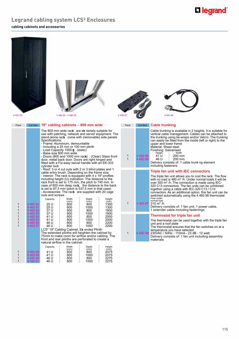
115
Legrand cabling system LCS³ Enclosurescabling cabinets and accessories
4 4 60 8 0 4 4 60 9 5 - 4 4 60 9 6 4 4 60 9 84 4 60 9 7
Pack C at.N os cabling cabinets mm wideTh e 8 00 mm wide racks are ext remely suitab le for use with patch ing , network and server eq uipment. Th e stand- alone racks come with ( removab le) side panelsSpecifications:- Frame: Aluminium, demountab le - I ncluding a 25 mm or 100 mm plinth- L oad C apacity 1500 kg ( static)- B ase size 8 00 mm wide- Doors ( 8 00 and 1000 mm racks) : ( C lear) G lass front door, metal b ack door. Doors are rig h t h ing ed and fitted with a Fix-easy swivel handle with an E -333 cylinder lock- Roof: 3 or 4 cut outs with 2 or 3 b lind plates and 1 cab le entry b rush . Depending on th e frame size- Interior: The rack is equipped with 4 x 19"-profiles including h eig h t ( U) indication. Th e distance to th e rack front is set to 17 5 mm, th e pitch to 7 4 0 mm. I n case of 8 00 mm deep racks, th e distance to th e b ack is set to 8 7 , 5 mm ( pitch is 537 , 5 mm in th at case)- Accessories: Th e racks are supplied with 20 cag e nuts and screws
C apacity W idth ( mm)
Depth ( mm)
Heig h t ( mm)
1 4 4 60 8 0 25 U 8 00 8 00 13001 4 4 60 8 1 25 U 8 00 1000 13001 4 4 60 8 2 37 U 8 00 8 00 18 001 4 4 60 8 3 37 U 8 00 1000 18 001 4 4 60 8 4 4 1 U 8 00 8 00 20001 4 4 60 8 5 4 1 U 8 00 1000 20001 4 4 60 8 6 4 6 U 8 00 8 00 22001 4 4 60 8 7 4 6 U 8 00 1000 2200
L C S3 19 " C ab ling C ab inet, E xt ended PlinthTh e ex tended plinth s will h eig h ten th e cab inet b y 75mm to make room for airflow and/or cabling. The front and rear plinth s are perforated to create a natural airflow in the cabinet.
C apacity W idth ( mm)
Depth ( mm)
Heig h t ( mm)
1 4 4 60 8 8 4 1 U 8 00 8 00 207 51 4 4 60 8 9 4 1 U 8 00 1000 207 51 4 4 60 9 0 4 6 U 8 00 8 00 227 51 4 4 60 9 1 4 6 U 8 00 1000 227 5
Pack C at.N os able trun ingC ab le trunk ing is availab le in 2 h eig h ts. I t is suitab le for vertical cab le manag ement. C ab les can b e attach ed to th e trunk ing using tie- wraps and/or V elcro. Th e trunk ing can easily be fitted from the inside (left or right) to the upper and lower frameMaterial: Sh eet steelFinish ing : G alvanised
Heig h t W idth1 4 4 60 9 5 4 1 U 200 mm1 4 4 60 9 6 4 6 U 200 mm
Delivery consists of: 1 cab le trunki ng element including fasteners
Triple fan unit with connectorsThe triple fan unit allows you to cool the rack. The flow with no load is 4 8 0 m³ /h . Under normal loads it will b e over 300 m³ /h . Th e connection is made using I E C -320 C 13 connectors. Th e fan units can b e comb ined tog eth er using a cab le with I E C - 320 C 13 / C 14 connectors. As an additional option, th is fan unit can b e switch ed automatically using th e 4 4 60 9 8 th ermostatFlow under normal load
1 4 4 60 9 7 310 m³ /hDelivery consists of: 1 fan unit, 1 power cab le, 1 ex tender cab le including fastening s
Thermostat for triple fan unit Th e th ermostat can b e used tog eth er with th e triple fan unit and a roof plateTh e th ermostat ensures th at th e fan switch es on at a temperature you h ave selected
1 4 4 60 9 8 230V AC / 50Hz - 110mA - 23 dB - 12 wattDelivery consists of: 1 fan unit including assemb ly materials
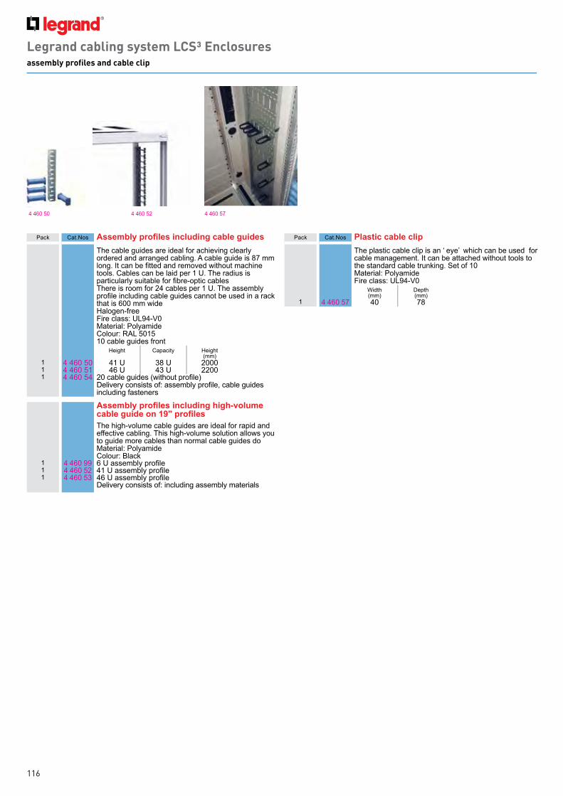
116
Legrand cabling system LCS³ Enclosuresassembly profiles and cable clip
4 4 60 50 4 4 60 52 4 4 60 57
Pack C at.N os ssembly profiles including cable guidesTh e cab le g uides are ideal for ach ieving clearly ordered and arrang ed cab ling . A cab le g uide is 8 7 mm long. It can be fitted and removed without machine tools. C ab les can b e laid per 1 U. Th e radius is particularly suitable for fibre-optic cablesTh ere is room for 24 cab les per 1 U. Th e assemb ly profile including cable guides cannot be used in a rack th at is 600 mm wideHalog en- freeFire class: UL 9 4 - V 0Material: PolyamideC olour: RAL 501510 cab le g uides front
Heig h t C apacity Heig h t ( mm)
1 4 4 60 50 4 1 U 38 U 20001 4 4 60 51 4 6 U 4 3 U 22001 4 4 60 54 20 cable guides (without profile)
Delivery consists of: assembly profile, cable guides including fasteners
ssembly profiles including high olume cable guide on profilesTh e h ig h - volume cab le g uides are ideal for rapid and effective cab ling . Th is h ig h - volume solution allows you to g uide more cab les th an normal cab le g uides doMaterial: PolyamideC olour: B lack
1 4 4 60 9 9 6 U assembly profile1 4 4 60 52 41 U assembly profile1 4 4 60 53 46 U assembly profile
Delivery consists of: including assemb ly materials
Pack C at.N os lastic cable clipTh e plastic cab le clip is an ‘ eye’ wh ich can b e used for cab le manag ement. I t can b e attach ed with out tools to th e standard cab le trunk ing . Set of 10Material: PolyamideFire class: UL 9 4 - V 0
W idth( mm)
Depth( mm)
1 4 4 60 57 4 0 7 8

117
Legrand cabling system LCS³ Enclosurescabling openrack and accessories
Legrand cabling system LCS³ Enclosureswall mounting enclosures
4 4 61 8 0
4 4 61 50 4 4 61 52 4 4 61 56 4 4 61 59
4 4 61 54
4 4 61 55 4 4 61 58
4 4 61 57
4 4 61 9 2
4 4 61 9 0 4 4 61 9 1
4 4 61 9 2
Pack C at.N os abling openrac and accessories1 4 4 61 50 Punch ed h ole ch annel rack , 7 ft x 24 " , b lack , 3/8 " sq uare
h ole 1 4 4 61 52 C ab le duct with door1 4 4 61 54 Hex anal cab le th roug h s ( set of 6)1 4 4 61 55 B end limiting clips ( set of 12)1 4 4 61 56 C ab le manag ement spools ( set of 4 )1 4 4 61 57 C ab le manag ement ring s1 4 4 61 58 Cable duct mounting brackets (top of rack Cablofil)1 4 4 61 60 Overh ead C ab le Path way, 5 U, 19 "1 4 4 61 59 Horizontal cab le manag er1 0 4 65 7 0 19 ' ' cab le manag er with cover - 1 U1 0 4 65 7 1 19 ' ' cab le manag er with cover - 2 U1 0 4 64 23 Screws
Pack C at.N os all mounting enclosures with glass door
Th e b asic frame consists of a wall element with an integrated strain relief profile, four bars running front to b ack , two cab le entry plates ( top and b ottom) and a set (2 pcs) of 19" profiles. The depth of the 19" profiles can b e adj usted in steps of 50 mm. Th e cab le h oles always fit because the installation engineer can change their size on the spot thanks to the handy bend-away fingers. The 19" profiles have a pattern of holes on the side to allow accessories to be fitted. The casing consists of two identical upper and lower panels with ventilation slots at th e rear, two identical side panels and a Securit g lass door with an E K - 333 cylinder lock with a h andleW idth : 600 mmC olour: RAL 7 04 7Finish ing : Powder coatingMax . load: 100 k gDelivery consists of: 1 rear plate, 4 depth wise b ars, 2 cable entry plates, 2 19" profiles, 2 roof and floor plates, 2 side panels, 1 g lass door, 1 assemb ly set, including assemb ly g uide
C apacity W idth ( mm)
Depth( mm)
Heig h t ( mm)
1 4 4 61 8 0 6 U 600 525 34 21 4 4 61 8 1 9 U 600 525 4 7 61 4 4 61 8 2 9 U 600 625 4 7 61 4 4 61 8 3 12 U 600 525 6091 4 4 61 8 4 12 U 600 625 6091 4 4 61 8 5 15 U 600 525 7 4 21 4 4 61 8 6 15 U 600 625 7 4 21 4 4 61 8 7 21 U 600 625 1009
ccessoriesable entry strip for wall enclosure
1 4 4 61 9 0 For dust- free cab le entry, instead of th e top and/or b ottom cab le entry plate. Suitab le for wall enclosureDelivery consists of: 1 ( 360 mm) cab le entry b rush , including fastening s
orner guide set1 4 4 61 9 1 Th e corner g uide set supports h eavy 19 " eq uipment.
The corners are fitted to the sides of the 19" profiles and th erefore do not use up any h eig h t units in th e front plane. Suitab le for wall enclosure Material: Sh eet steelC olour: SendzimirDelivery consists of: 1 corner g uide support ( left) , 1 corner g uide support ( rig h t) , including fastening materials
oof plate with integrated fan unitTh is fan unit can b e added as an option to g enerate a forced flow of cooling air through the wall enclosure. To do th at, th e ex isting roof panel must b e removed and replaced with th is C at.N o. Th e 4 4 60 9 8 th ermostat can b e used in comb ination with th is roof plate. Delivery consists of: 1 roof plate with 2 fan units, including assemb ly materials
1 4 4 61 9 2 525 mm ( d)1 4 4 61 9 3 625 mm ( d)

118
Pack C at.N os cable feedthrough panelsTh ey ensure th e correct arrang ement and routing of th e patch cords. RAL 9 005 b lack
etal 2 a es uic iHorizontal feedth roug h passag e. W ith cab le ring s plastic cab le g uide with controlled radius for optimum cord protection ( compliance with th e b ending radius) Q uick installation with out screws
1 0 4 65 22 1 U
11
1
0 4 65 236 4 65 20
6 4 65 21
2 UC ab le mg t feedth ru panel 19 " 1Umetal screw fix blackC ab le mg t feedth ru panel 19 " 2Umetal screw fix black
lastic with brush direct clipping1 0 4 65 28 1 U1 0 4 65 29 2 U
etal with brush uic iQ uick installation with out screws
1 0 4 65 30 1 U1 0 4 65 31 2 U1 6 4 65 20 C ab le patch cord manag ement b ar 1U metal screw
fix black1 6 4 65 21 C ab le patch cord manag ement b ar 1U metal screw
fix black
front panel25 4 4 62 10 Th e plastic front panel serves to seal off th e 19 "
area so th at it is airtig h t. Th e front panel h ave b een specially desig ned to make installation easy and to form an airtig h t 19 " seal. Th e front panel is easy to mount between the 19" profiles. No materials are needed for securing th e front panel. Air tig h t accessories enab le energ y saving s b y preventing air leaka g ePlastic RAL 9 005, 25 pieces
blan ing platesRAL 9 005 b lack
lastic direct clipping1 0 4 65 32 1 U1 0 4 65 33 2 U
etal uic iQ uick installation with out screws
1 0 4 65 38 1 U1 0 4 65 39 2 U1 0 4 65 4 0 3 U
lighting it19 " metal panel eq uipped with a lig h ting ki t with switchQ uick installation with out screwsSupplied with fluorescent tube 230 V A - 8 W
1 0 4 64 8 5 1 U
Legrand cabling system LCS³ Enclosures19” accessories
0 4 65 230 4 65 22
0 4 65 320 4 65 29

119
Pack C at.N os i ed shel esFor 19 " cab inets and server cab inets, B ati rack s and Altis cab inets Q uick installation with out screws. RAL 9 005 b lack
uspended installation on 2 risersHeig h t 2 U. Maxi mum load 15 kg
1 0 4 65 00 Depth 115 mm1 0 4 65 01 Depth 200 mm1 0 4 65 02 Depth 360 mm
nstallation on risersHeig h t 1 U. Maxi mum load 50 kg
1 0 4 65 05 Sh elf depth 4 25 mm For depth 600 mm
1 0 4 65 06 Sh elf depth 625 mm For depth 8 00 mm
1 0 4 65 07 Sh elf depth 8 25 mm For depth 1000 mm
Telescopic shel es For 19 " cab inets and server cab inets, B ati rack s and
Altis cab inets Q uick installation on 4 x 19 " risersHeig h t 1 U. Maxi mum load: 50 kg . RAL 9 005 b lack
1 0 4 65 08 Sh elf depth 4 25 mm For depth 600 mm
1 0 4 65 09 Sh elf depth 625 mm For depth 8 00 mm
1 0 4 65 10 Sh elf depth 625 mm For depth 1000 mm
ea y duty shel esMaxi mum load: 100 kg Fastening to th e 4 x 19 " risers using screws. RAL 9 005 b lack
1 0 4 65 17 Fixe d sh elf, depth 8 20 mm, 1 UFor cab inets with depth 1000 mm and server cab inets
1 0 4 65 18 Telescopic sh elf, depth 8 20 mm, 2 UFor server cab inets
eyboard shelfFor 19 " cab inets and server cab inets, B ati rack s and Altis cab inetsFor depth 8 00 mm and 1000 mmFastening to th e 4 x 19 " risers using screws Maxi mum load: 50 kg . RAL 9 005 b lack
1 0 4 65 19 I t can accept: - a computer screen- a ke yb oard on retractab le support- a mouse on a sliding sh elf with b uilt- in pad mouse or C D h ousing
et of 2 fi ed guide railsFor 19 " cab inets and server cab inets, racks and Altis cab inetsI nstallation on 4 x 19 " risersMaxi mum load: 50 kg
1 0 4 65 11 For depth 600 mm1 0 4 65 12 For depth 8 00 mm1 0 4 65 13 For depth 1000 mm
Pack C at.N os i ed shel es1 4 4 62 15 Sh elf, variab le 100k g - 19 " x 7 00 x 25mm
( w x d x h ) - RAL 9 0111 4 4 62 11 C ab le entry plate - 19 " x 1, 5mm x 2 U ( l x d x h ) RAL
9 0111 4 4 62 12 C ab le entry foam - 19 " x 2 U RAL 9 011
Temperature management entilation drawers
For internal air circulation. Fix on 2 x 19 " uprig h ts ON /OFF switch . Supplied with power supply cord 230V ~B lack RAL 9 005
1 0 4 64 8 9 Drawer with 2 fansDepth 150 mm
1 0 4 64 9 0 Drawer with 4 fansDepth 300 mmThermostat
1 0 34 8 4 8 Adj ustab le from 5 to 60 ° C , 230 V A, 50/60 Hz N C contact ( 5 A) and N O contact ( 10 A) Mag net fastening
i ing screwsSet of 50 cag e nuts, 50 plastic wash ers and 50 x M6 screws
1 0 364 54 W ith 9 .5 mm cag e nuts
elf adhesi e document holderspen
E xt . dimensions I nt. dimensions
Heig h t( mm)
W idth( mm)
Heig h t( mm)
W idth( mm)
Depth( mm)
1 0 365 8 0 235 34 0 200 310 181 0 365 8 1 165 260 130 230 18
losed 1 0 365 8 2 Rig id plastic - I P 50
I nt. dimensions: 324 x 120 x 18 mmTransparent
1 0 09 7 9 9 Soft plastic, A4 - 305 x 220 mm
0 4 65 06
0 4 65 01 0 4 65 22
0 4 65 29
Legrand cabling system LCS³ Enclosures19” accessories (continued)
4 4 62 15 4 4 62 11

120
Legrand cabling system nergy istributions
Pack C at.N os ith ammeter
Measure consumption to provide b etter installation manag ement:b alancing circuits, displaying availab le capacity, preventing overloads and power failures1 ammeter per circuitRotating display to ensure a perfect reading wh atever th e PDU mounting direction is ( h orizontal, vertical with top or b ottom power supply input)
2 standard1 6 4 68 65 20 C 13 outlets + 4 C 19 outlets with cord lock ing
system. C onnection on terminal b lock up to 6 mm2
To provide A electric power for I T eq uipments in 19 " enclosuresSing le ph ase 230 V - 50/60 Hz power supplyZ ero- U PDU for vertical mounting in th e cab inetPDU with 2 circuits protected b y 16 A uni+ neutral MC B in a support with proj ecting edg es to avoid accidental b reak downEach circuit is identified by color codingTh e total numb er of outlets is distrib uted eq ually b etween th e 2 circuits330° rotating cab le input for a perfect orientation of th e cab le and no interference in th e cab inet2P+ E outlets: - C 13 and C 19 standard outlets are eq uipped with cord lock ing system to avoid any accidental disconnection. Universal solution compatib le with all th e cords ( C 14 plug s for C 13 and C 20 plug s for C 19 )- French , G erman and B ritish standard outlets are eq uipped with b lank s- French and G erman standard outlets are inclined at 55°Delivered with 2 sets of metallic mounting b rack ets:- Button brackets. For quick fixing and variable pitch- Standard brackets. For screw fixingBlack modules (outlets and functions). Aluminium profileTo provide A electric power for I T eq uipments in 19 " enclosuresTh ree ph ase 38 0 V - 50/60 Hz power supplyZ ero- U PDU for vertical mounting in th e cab inetE ach circuit is protected b y 16 A sing le pole MC B in a support with proj ecting edg es to avoid accidental b reak down1 circuit per ph ase, each with 6 I E C 60320 C 13 outlets and 2 I E C 60320 C 19 outlets330° rotating cab le input for a perfect orientation of th e cab le and no interference in th e cab inet C 13 and C 19 standard outlets are eq uipped with cord lock ing system to avoid any accidental disconnection. Universal solution compatib le with all th e cords ( C 14 plug s for C 13 and C 20 plug s for C 19 )Delivered with 2 sets of metallic mounting b rack ets:- Button brackets. For quick fixing and variable pitch- Standard brackets. For screw fixingB lack modules ( outlets and functions)Aluminium profile
6 4 68 616 4 68 53
Pack C at.N os tandard
2 standard1 6 4 68 56 24 C 13 outlets with cord lock ing system
C onnection on terminal b lock up to 6 mm2
1 6 4 68 57 24 C 13 outlets with cord lock ing system3 m power supply cord with I E C 60309 32 A 2P+ E plug
1 6 4 68 60 20 C 13 outlets + 4 C 19 outlets with cord lock ing system. C onnection on terminal b lock up to 6 mm2
1 6 4 68 61 20 C 13 outlets + 4 C 19 outlets with cord lock ing system. 3 m power supply cord with I E C 60309 32 A 2P+ E plug

121
Legrand cabling system nergy istributions
6 4 68 7 5
T T T T
V ery easy to identify th ank s to th e orang e b uttons nex t to each outlet
To provide A electric power for I T eq uipments in 19 " enclosuresSing le ph ase 230 V - 50/60 Hz power supplyZ ero- U PDU for vertical mounting in th e cab inetPDU with 2 circuits protected b y 16 A uni+ neutral MC B in a support with proj ecting edg es to avoid accidental b reak downEach circuit is identified by color codingTh e total numb er of outlets is distrib uted eq ually b etween th e 2 circuits330° rotating cab le input for a perfect orientation of th e cab le and no interference in th e cab inet2P+ E outlets: - C 13 and C 19 standard outlets are eq uipped with cord lock ing system to avoid any accidental disconnection. Universal solution compatib le with all th e cords ( C 14 plug s for C 13 and C 20 plug s for C 19 )- French , G erman and B ritish standard outlets are eq uipped with b lank s- French and G erman standard outlets are inclined at 55°Delivered with 2 sets of metallic mounting b rack ets:- Button brackets. For quick fixing and variable pitch- Standard brackets. For screw fixingBlack modules (outlets and functions). Aluminium profileTo provide A electric power for I T eq uipments in 19 " enclosuresTh ree ph ase 38 0 V - 50/60 Hz power supplyZ ero- U PDU for vertical mounting in th e cab inetE ach circuit is protected b y 16 A sing le pole MC B in a support with proj ecting edg es to avoid accidental b reak down1 circuit per ph ase, each with 6 I E C 60320 C 13 outlets and 2 I E C 60320 C 19 outlets330° rotating cab le input for a perfect orientation of th e cab le and no interference in th e cab inet C 13 and C 19 standard outlets are eq uipped with cord lock ing system to avoid any accidental disconnection. Universal solution compatib le with all th e cords ( C 14 plug s for C 13 and C 20 plug s for C 19 )Delivered with 2 sets of metallic mounting b rack ets:- Button brackets. For quick fixing and variable pitch- Standard brackets. For screw fixingB lack modules ( outlets and functions)Aluminium profile
Pack C at.N os tandard
2 standard1 6 4 68 7 0 18 C 13 outlets + 6 C 19 outlets with cord lock ing
system. 3 m power supply cord with I E C 60309 32 A 3P+ N + E plug
ith ammeterMeasure consumption to provide b etter installation manag ement:b alancing circuits, displaying availab le capacity, preventing overloads and power failures1 ammeter per circuitRotating display to ensure a perfect reading wh atever th e PDU mounting direction is ( h orizontal, vertical with top or b ottom power supply input)
2 standard1 6 4 68 7 5 18 C 13 outlets + 6 C 19 outlets with cord lock ing
system. 3 m power supply cord with I E C 60309 32 A 3P+ N + E plug

122
Pack C at.N os standard
2 standardC onnection on terminal b lock ( ex cept C at.N o 6 4 68 15)
1 6 4 68 14 10 C 13 outlets with cord lock ing system1 6 4 68 15 12 C 13 outlets with cord lock ing system
3 m power supply cord with 16 A I E C 60309 2P+ E1 6 4 68 09 6 C 13 outlets + 2 C 19 outlets with cord lock ing
system1 6 4 68 07 6 C 19 outlets with cord lock ing system
To provide A electric power for IT equipments in enclosures. 230 V - 50/60 Hz power supply. 1U aluminium profile. End cap with metallic brackets and cable holder shape. Quick fixing (no screws) on 19" fixing centers. Can also be installed vertically by reverting the brackets (no screws).2P+ E outlets: - C 13 and C 19 standard outlets are eq uipped with cord lock ing system to avoid any accidental disconnection. Universal solution compatib le with all th e cords ( C 14 plug s for C 13 and C 20 plug s for C 19 ) .B lack modules ( outlets and functions)
E nd cap with cab le h older sh ape
Quick fixing
Legrand cabling system nergy istributions

123
To provide A electric power for IT equipments in enclosures. 230 V - 50/60 Hz power supply. 1U aluminium profile. End cap with metallic brackets and cable holder shape. Quick fixing (no screws) on 19" fixing centers. Can also be installed vertically by reverting the brackets (no screws).2P+E outlets: - C13 and C19 standard outlets are equipped with cord locking system to avoid any accidental disconnection. Universal solution compatible with all the cords (C14 plugs for C13 and C20 plugs for C19).Black modules (outlets and functions)
Pack Cat.Nos 19” - PDU with ammeter
Measure consumption to provide better installation management:balancing circuits, displaying available capacity, preventing overloads and power failuresMeasure total PDU currentRotating display to ensure a perfect reading whatever the PDU mounting direction is (horizontal, vertical with top or bottom power supply input)IEC 60320 standardWith integrated universal plug locking systemConnection on terminal block
1 6 468 43 6 C13 outlets with cord locking system1 6 468 45 6 C13 outlets + 1 C19 outlet with cord locking system1 6 468 44 6 C19 outlets with cord locking system
6 468 43
Legrand cabling system LCS³ Energy DistributionPDUs

124
0 465 46 + 0 465 47
Pack Cat.Nos PDU to be equippedFor self assembly with Mosaic wiring device modulesQuick fixing (no screws) on 19" uprightsAluminium profile
1 6 468 99 PDU 19"Capacity: 16 Mosaic modules
1 6 468 98 PDU 10"Capacity: 8 Mosaic modules
PDU accessoriesLocking capsTo block the use of an outlet. A key is necessary to remove the cap and free the access Light grey
1 6 468 90 Set of 6 locking caps for French and German standard outlet + 1 key
1 6 468 92 Set of 6 locking caps for British standard outlet + 1 key1 6 468 94 Set of 6 locking caps for C13 standard outlet + 1 key1 6 468 95 Set of 6 locking caps for C19 standard outlet + 1 key
Surge protection moduleTo replace used module on PDUWith light indicators:- one LED (white) gives information whether the PDU is supplied with power or not- one LED (green) indicates when surge protection module is efficient or must be replacedHotswappable: replacement keeping the PDU and its outlets powered on
1 6 468 97 Surge protection replacement module
Pack Cat.Nos Multi-applications DIN railFor mounting modular devices (circuit breakers, Legrand multimedia network components, etc)Capacity: 24 modulesHeight 4 UScrew fixing on 19" uprights(1)
1 0 465 46 DIN profile rail with front panelSupplied with blanking plates24 modulesBlack RAL 9005
1 0 465 47 Rear coverTo be used for high current applications(greater than 50 V)Used with Cat.No 0 465 46Ensures IP XXBSupplied with terminal block(8 + 1 connections)
6 468 90
Legrand cabling system LCS³ Energy DistributionPDUs

125
Legrand cabling system LCS³
n Dimensions (mm)
n Performance in case of installation with zone distribution box (consolidation point)Maximum recommended lengths for the connections, in order to guarantee system performance when using copper feedthrough RJ 45 sockets and/or RJ 45 sockets
Associated length (m)ConnectionsCords Cables
Cat. 6A
81520
706055
787575
Cat. 681520
706055
787575
Cat. 5e81520
756560
838080
The use of cables as short as possible is recommended, in order to increase flexibility as far as cord lengths in case of reconfiguration
352137,1166
49,8
n Maintenance performanceLegrand guarantees the long-term performance of the LCS³ system by providing a 25-year performance guarantee
n Performance table
n Compliance with LCS³ system standards and approvals
n New denominations of LAN cables (according to ISO 11801-2)
LCS³ 8 LCS³ 6A LCS³ 6 LCS³ 5eFrequency 2000 MHz 500 MHz 250 MHz 100 MHzDelivery 40 Gbit/s 10 Gbit/s 1 Gbit/s 1 Gbit/sWiring Copper Copper FO Copper FO CopperConnectors RJ 45 RJ 45 SC-LC… RJ 45 SC-LC… RJ 45Max. cable length 30 m 100 m variable 100 m variable 100 m
The LCS³ system and its components (de-embedded) comply with the current standards:- EIA/TIA 568 B2.10- EN 50173-1 and EN 50173-2- ISO/IEC 11801 edition 3 (2017)The LCS³ system supports 10 G applicationsBase T up to 100 m in a transmission channel in compliance with ISO/IEC 11801 edition 3.0 (2017) and EIA/TIA 568 C2-1 standardsThe class I link of the LCS³ system is also compliant with ISO/IEC 11801 edition 3.0 (2017) and EIA/TIA 568 C2-1 standards. LCS³ systems are certified by the independent lab 3P, a point of reference for the sector
They indicate: "Type of cable shielding" / "type of twisted pair shielding" followed by TP (twisted pairs)
n Main characteristics of LCS3 systems
Twisted pairshielding
Cableshielding
Cable type
Cable shielding
Twisted pair
shieldingold denomination
new denomination
SSTP S/FTP S: screen consisting of a copper braid
F: screen consisting of alu/polyester ribbon
SFTP SF/UTP SF: ribbon + braid association
U: no screen
STP U/FTP U: no screen F: screen consisting of alu/polyester ribbon
FTP F/FTP F: screen consisting of alu/polyester ribbon
F: screen consisting of alu/polyester ribbon
FTP F/UTP F: screen consisting of alu/polyester ribbon
U: no screen
UTP U/UTP U: no screen U: no screen
SIZES OF COMPONENTS LINK SIZES (CHANNEL)
Supported network protocol
Cat. 8 STP Cat. 6A STP Cat. 6 UTP Cat. 6 FTP Class I Class Ea Class E2000 MHz 500 MHz 250 MHz 250 MHz 2000 MHz 500 MHz 250 MHz 250 MHz40 Giga 10 Giga 1 Giga 1 Giga 40 Giga 10 Giga 1 Giga 1 Giga
Attenuation (dB) Signal loss
LCS3
ISO 11801 edition 3 1.50.13
0.45 max
0.06
0.32 max
0.09
0.32 max32.7
35.4
42.1 max
24.1
28.9 max
25.7
30.7 max
Return loss (dB)Resistance to echo
LCS3
ISO 11801 edition 3 1.217.05
14 min
26.59
20 min
29.8
16 min8
16.4
8 min
22.1
10 min
38.8
10 min
Next (dB)Resistance to disturbances between pairs(1)
LCS3
ISO 11801 edition 3 12.937.46
37 min
56.93
46 min
51.3
46 min9.8
38.1
29.2 min
54
35.3 min
53.9
35.3 min
Performance stability and long-lasting product capabilities guaranteed for a POE signal up to 100 W
25-year guarantee: Legrand guarantees the long term performance of the LCS3 system at legrand.com
The Innoval training center gives the possibility of obtaining LCS³ approval at legrand.com
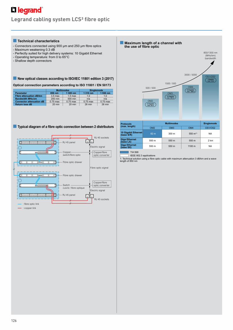
126
for example : xxxxxxxTM
xxxxxxxx
for example : xxxxxxxTM
xxxxxxxx
for example : xxxxxxxTM
xxxxxxxx
for example : xxxxxxxTM
xxxxxxxx
Legrand cabling system LCS³ fibre optic
850/1300 nm(MHz/km)bandwidth
OS1/OS2
OM3
1500 / 500
3500 / 5000
OM2
500 / 500 OM4
550
2
n Technical characteristics- Connectors connected using 900 µm and 250 µm fibre optics- Maximum weakening 0.3 dB- Perfectly suited for high delivery systems: 10 Gigabit Ethernet- Operating temperature: from 0 to 65°C- Shallow depth connectors
n New optical classes according to ISO/IEC 11801 edition 3 (2017)
Optical connection parameters according to ISO 11801 / EN 50173
n Typical diagram of a fibre optic connection between 2 distributors
RJ 45 panel
RJ 45 panel
Electric signal
Copper/fibre optic converter
Copper/fibre optic converter
Electric signal
Fibre optic signal
Copper switch/fibre optic
Switchcuivre / fibre optique
Fibre optic drawer
RJ 45 sockets
RJ 45 sockets
Fibre optic drawer
Table 2
2
Table 1
: fibre optic link
: copper link
1
n Maximum length of a channel with the use of fibre optic
Multimodes SinglemodeParameter 850 nm 1 300 nm 1 310 nm 1 550 nmFibre attenuation dB/km 3.5 max 1.5 max 1.0 1.0Bandwidth MHz.km 200 min 500 min n/a n/aConnector attenuation dB 0.75 max 0.75 max 0.75 max 0.75 maxReturn loss dB 20 min 20 min 26 min 26 min
Protocols (max. length)
Multimodes Singlemode
OM2 OM3 OM4 OS1/OS2
10 Gigabit Ethernet (base S/R) 82 m 300 m 550 m(1) NA
Giga Ethernet (base LX) 550 m 550 m 550 m 2 km
Giga Ethernet (base SX) 550 m 550 m 1100 m NA
1: Technical solution using a fibre optic cable with maximum attenuation 3 dB/km and a wave length of 850 nm
TIA 568IEEE 802.3 applications

127
Legrand cabling system LCS3 Energy distributionPDU Zero-U
n PDU Zero-U
n PDU Zero-U sizes (mm)
D
E
C
B F A
Cat.NosHeight Width Depth Fixing centers
(mini-maxi)A B(1) C D E(2) F(1)
6 468 50 1250 1294 52 52.5 87 1262-1292
6 468 51 1250 1294 52 52.5 87 1262-1292
6 468 52 1250 1294 52 52.5 87 1262-1292
6 468 53 1250 1294 52 52.5 87 1262-1292
6 468 54 1466 1510 52 52.5 87 1478-1508
6 468 56 1034 1078 52 52.5 87 1046-1076
6 468 57 1034 1078 52 52.5 87 1046-1076
6 468 60 1070 1114 52 52.5 87 1082-1112
6 468 61 1070 1114 52 52.5 87 1082-1112
6 468 65 1160 1204 52 52.5 87 1172-1202
6 468 70 1340 1384 52 52.5 87 1352-1382
6 468 75 1475 1519 52 52.5 87 1487-1517
1 : Overall height with standard brackets (screw fixing)2 : Overall depth at the circuit breaker slot
6 468 50 6 468 526 468 51
3 m
6 468 53
3 m
6 468 56 6 468 57
3 m
6 468 60 6 468 61
3 m
6 468 65
AM
PA
MP
6 468 70
3 m
6 468 75
3 m
AM
PA
MP
AM
P
6 468 54

NOTES

NOTES

NOTES


New Zealand106-124 Target RoadGlenfield, Auckland 0627Tel: 0800 476 009Fax: 0800 476 329Web: www.legrand.co.nz
AustraliaBuilding 4 Nexus Industry Park43-47 Lyn Pde, Prestons, NSW 2170Tel: 1300 369 777Web: www.legrand.com.au
v1 -
Feb
ruar
y 20
18