performance improvement of buck-boost converter using ... · abstract ² the buck - boost converter...
TRANSCRIPT
International Journal of Engineering Research And Management (IJERM)
ISSN : 2349- 2058, Volume-04, Issue-10, October 2017
22 www.ijerm.com
Abstract— The Buck - boost converter is a system to step-down
and step-up a DC source. But if the voltage of DC source and the
load in the fluctuative condition, the output voltage of the
Buck-boost converter is not stable. In this research, Fuzzy logic
controller used to make Buck-Boost converter can adapt load
and DC voltage variation to produce a stable DC output.
Converter built using MOSFET, PWM signal in the frequency 4
kHz and voltage of DC source in the 30 V to 60 V. Fuzzy logic
controller built using Matlab Simulink and connected to
Converter by PCI 1710HG. This controller made PWM duty
cycle in accordance with the changing of set point and input
voltage. The experiment result shown that the converter output
can produce voltage in the set point although in fluctuated input
voltage.
Index Terms— Buck-boost Converter, Duty Cycle, Pulse
Width Modulation, PCI 1710HG, Fuzzy Logic, Simulink
Matlab
I. INTRODUCTION
In electric automobiles, trolley cars, marine hoists, forklift
trucks, and renewable energy system need provide smooth
acceleration control, high efficiency, and fast dynamic
response. Usually they use dc-dc converter system to do it.
They using step down, step-up, or step up- step-down the
voltage of electric power. So, there are many types of DC-DC
convertor, which is buck converter, boost converter, and
buck-boost convertor [1-5]. Buck-boost converter is one type
of converter circuit that the most used in power electronics
appliances. The designers choose this converter because the
output voltage is inverted from the input voltage, and the
output voltage can be either higher or lower than the
source voltage.
Manuscript received Oct 09, 2017
B. Sujanarko, Department of Electrical Engineering, Faculty of
Engineering, University of Jember, Jember, Indonesia
I. Syafrizal, Department of Electrical Engineering, Faculty of
Engineering, University of Jember, Jember, Indonesia
S. Bachri, Department of Electrical Engineering, Faculty of
Engineering, University of Jember, Jember, Indonesia
R.B.M. Gozali, Department of Electrical Engineering, Faculty of
Engineering, University of Jember, Jember, Indonesia
S. Prasetyo, Department of Electrical Engineering, Faculty of
Engineering, University of Jember, Jember, Indonesia
T. Hardianto Department of Electrical Engineering, Faculty of
Engineering, University of Jember, Jember, Indonesia
The control point of view due to their intrinsic nonlinearity is
an intriguing subject, because the presence of parasitic
elements, time-varying loads, and supply voltages fluctuation
[1-4]. There are many classical nonlinear controllers have
been proposed, like sliding mode control strategies, nonlinear
PI controllers, linear averaged controller, feedback
linearizing controller, passivity-based controller and others.
The major problem of the classical approach are the
complexity of system, the difficult to make precise, and the
difficult to make significant statements about its behavior
[3-8].
Another controll that using human linguistic terms and
common sense is Fuzzy Logic Controllers (FLC). Many FLC
have been developed. The essential parts of the FLC are
make a set of linguistic rules related by the fuzzy implication
and the rule of inference. Each ways in the determining of
these parts also produce the difference of Buck-Boost
converter performance [5-8]. A method and some values are
needed to determine the essensial parts, so the buck-boost
converter has high performances.
In this research, the FLC implemented on Simulink atlab
and connect to Buck-Boost converter using PCI 1710HG.
Such this implementation will allow to make variation of the
essential parts of FLC, so that the best performance can be
achieved.
II. BUCK-BOOST CONVERTER MODELLING
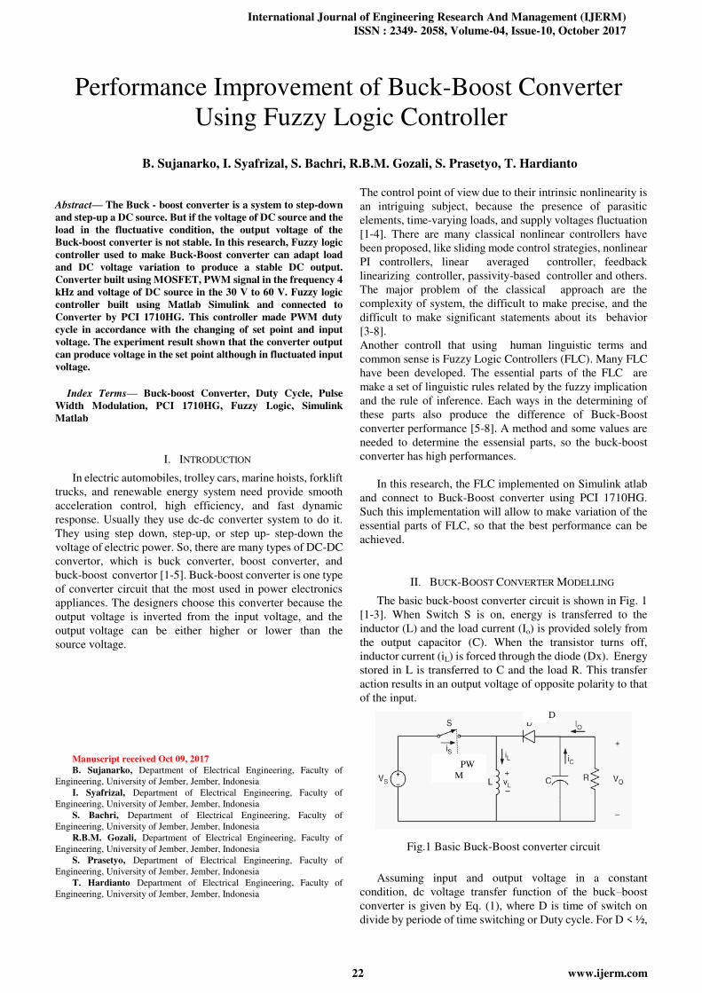
The basic buck-boost converter circuit is shown in Fig. 1
[1-3]. When Switch S is on, energy is transferred to the
inductor (L) and the load current (Io) is provided solely from
the output capacitor (C). When the transistor turns off,
inductor current (iL) is forced through the diode (Dx). Energy
stored in L is transferred to C and the load R. This transfer
action results in an output voltage of opposite polarity to that
of the input.
Fig.1 Basic Buck-Boost converter circuit
Assuming input and output voltage in a constant
condition, dc voltage transfer function of the buck–boost
converter is given by Eq. (1), where D is time of switch on
divide by periode of time switching or Duty cycle. For D < ½,
Performance Improvement of Buck-Boost Converter
Using Fuzzy Logic Controller
B. Sujanarko, I. Syafrizal, S. Bachri, R.B.M. Gozali, S. Prasetyo, T. Hardianto
D
PW
M

Performance Improvement of Buck-Boost Converter Using Fuzzy Logic Controller
23 www.ijerm.com
the output magnitude is less than the input voltage magnitude,
while for D > ½, the output voltage is greater in magnitude
than the input voltage. While, the value of the inductor that
determines the boundary between the Continuous Current
Mode (CCM) and Discontinuous Current Mode (DCM) is
given by Eq. (2) [1-8].
III. PULSE WIDTH MODULATION IN THE BUCK-BOOST
CONVERTERS
As shown in Eq.(1) and Eq. (2), the output voltage is
depend on duty cycle (D) of Pulse Witdh Modulation (PWM)
cicuit, beside the inductor value, load, and parasitic value.
Fig. 2 show an PWM principal [3-5] . A voltage level from a
controller, as represents a desire output voltage, entered into
the non inverting of comparator, and a sawtooth pulse, as
carrier wave, entered into inverting of comparator. These
system then generate pulse ouput in the certain duty cycle.
This pulse then trigger power electronic device and produce
average dc output voltage that comparable with a given
desired level on non inverting.
Comparator
Fig.2 Pulse Width Modulation circuit
Usually, the input voltage (Vs) and output (V0) may
fluctuate. To determine a certain average output voltage in the
constan value, the converter used a controller. This controller
aims to regulate duty cycle. If the input or the ouput voltage is
decrease the duty cycle then increase, and otherwise if the
input or the output voltage increase the duty cycle then
decrease.
Various control methods are available for buck boost
converters. One method of control is to use sliding mode
control. But its lack effective control [3-5]. Another
alternative is a decoupled control scheme using PI controllers
[9]. For high-performance applications, a PI controller
cannot guarantee a perfect tracking in the case of a periodic
reference, according to the internal model principle. So a non
linear control method using fuzzy logic is proposed in this
paper.
IV. FUZZY CONTROL IN BUCK-BOOST CONVERTER
The concept of Fuzzy Logic was introduced by Lotfi
Zadeh in 1965. It is mathematical modeling which is deals
with uncertainty and offers an important concept of soft
computing with words [6-7]. The generic structure of fuzzy
logic controller is shown in Fig. 3. It has four main
components, Fuzzifier, Rule Base, Inference Engine, and
Defuzzifier [4-7].
Fuzzifier is a part of FLC that modifies the inputs so that
they can be interpreted and compared to the rules in the
rule-base. It convert crisp values to fuzzy values. Fuzzy
values are linguistic variables. Error, load voltage,
modulation index, etc is example of input. This input then
convert to a set of linguistic values, like positive, zero,
negative.
Intent of the linguistic values is quantified using
membership functions. The membership function range input
from 0 to 1. There are different types of membership
functions, triangular, trapezoidal, gaussian, bell, sigmoidal,
S, pi etc [4-8].
Fig.3 Generic structure of fuzzy logic controller
Rule Base is a part of FLC that holds the knowledge, in the
form of a set of rules, in the IF-THEN statements. This part
has function to achieve good control. Inference engine is a
part of FLC that decision making mechanism. Based on the
inputs, inference engine evaluates which control rules are
relevant at the current time and then decides what the input to
the plant should be. It has a goal is to find best control the
plant.
There are two types of fuzzy inference engine, Mamdani
and Sugeno method. Mamdani’s method is widely accepted
for capturing expert knowledge. But it has computational
burden. Sugeno is computationally efficient. It is highly
attractive in control problems particularly dynamic non linear
systems. The Sugeno output membership functions are linear
or constant.
Defuzzification is a part of FLC that converts the
conclusions of the inference mechanism into the actual
outputs. It converts the fuzzy value to crisp value. Centroid,
max membership principle, mean-max membership, centre of
sums, weighted average, centre of largest area various of
defuzzification method.
V. MATERIAL AND METHOD
A. System Configuration
Fig. 4 show configuration system in the research. The
system consists power supply with a voltage of 30 V - 60 V,
voltage sensor that used to read the value of the power supply
voltage and converter output, current sensor that used to read
the converter current or that flow to the load, driver that used
as control and separator between power signal and the real
power, PWM circuit that produce signal to trigger converter,
PCI 1710 HG and PCLD 8710 that used as a interfacing
(1)
(2)
a level voltage
from controller
Triangle
waveform Pulse

International Journal of Engineering Research And Management (IJERM)
ISSN : 2349- 2058, Volume-04, Issue-10, October 2017
24 www.ijerm.com
between computer and external device, and Fuzzy logic
controller that used to produce a voltage as control of the
magnitude of the PWM duty cycle.
B. Buck-Boost Converter Circuit
Buck-boost converter circuit consists of MOSFET, diode,
inductor and capacitor. This circuit shown at Fig. 5. Tipe and
value of each component have been also shown in this figure.
MOSFET used as electrical switches that controls by PWM.
Changes in the average voltage at the output is due to differing
value of the duty cycle. If the duty cycle (D) <50%, the value
of the output voltage will be smaller than the input voltage and
when D > 50%, then the value of the output voltage will be
greater than the input voltage.
Fig.4 System configuration
Fig. 5 Buck-boost converter circuit
C. MOSFET Driver Circuit
MOSFETs with certain types will have specific
specifications. Thus, the pulses entering the Gate of the
MOSFET must also have certain shape, amplitude and
frequency. The shape must primarily meet to dv/dt and di/dt.
Suitable amplitude will make the MOSFET have a small Ron
so the heat dissipation is small. While the corresponding
frequency, will be able to work MOSFET at maximum
current.
For that purpose, a MOSFET driver circuit is needed. This
circuit will form the pulses of the PWM, so it has the shape
and voltage corresponding to the MOSFET specification. For
frequency it has been adjusted by using triangular wave with
certain frequency in the PWM cicuit. The MOSFET driver
circuit is shown in Fig. 6. MOSFET driver circuit also serves
as a separator between power for control with power system.
Fig. 6 MOSFET Driver circuit
D. PWM Circuit
PWM circuit shown in Fig. 7. It is consist of IC LM324 as
comparator and NE 555 as triangular signal. The triangular
signal that generated from the IC NE555 enter to inverting
input and the output voltage from fuzzy logic control enter to
non-inverting input. The result of the comparing then enter to
MOSFET driver circuit.
Fig. 7 PWM Circuit
E. Voltage and Current Sensor
The input and output voltage measure using voltage divider
circuit. This voltage divider convert the input and output
voltage of the converter in the 60 V (max) in to less than 5V.
This sensor shown in Fig.8(a). Current sensor used in the
system is ACS712-20A. It is a Hall Effect current sensors. Fig.
8(b) shown this sensor.
(a) Voltage Sensor
(b) Current Sensor
Fig. 8 Sensors
F. Fuzzy Logic Controller Design
Fuzzy logic controller modeled for buck boost converter
is shown in Figure 9. It have two input, that is voltage output,
and error of converter. The ouput of FLC is a voltage that
enter to PWM circuit. In the FLC, three signals, then
Fuzzyfier into some membership. Fig. 10 show the
membership for these signals.

Performance Improvement of Buck-Boost Converter Using Fuzzy Logic Controller
25 www.ijerm.com
Fig. 9 Fuzzy Logic Controller Model
Fig. 10 Input and output membership of FLC
Based on these memberships, the next step is build the
Fuzzy role decision that represent the correlation among the
inputs and outputs signal, as shown in table 1. The next step is
construct Rule base using IF-THEN logic. The rule base
shown in Fig. 11. All process done using Fuzzy Logic toolbox
of Matlab.
If set-point is NB and V-out is NB and V-in is NB
then V-komparator is Z
.........
If set-point is NS and V-out is NB and V-in is NB
then V-komparator is PS
.......... If set-point is Z and V-out is NB and V-in is NB
then V-komparator is PB
.............
If set-point is PS and V-out is NB and V-in is NB
then V-komparator is PB
............
If set-point is PB and V-out is NB and V-in is NB
then V-komparator is PB
...............
If set-point is PB and V-out is PB and V-in is PB
then V-komparator is Z
Fig. 11 Rule Base
Table 1 Fuzzy rules
Set-point =NB V-in
NB NS Z PS PB
V-out
NB Z NB NB NB NB
NS NS NB NB NB NB
Z NB NB NB NB NB
PS NB NB NB NB NB
PB NB NB NB NB NB
Set-point =NS V-in
NB NS Z PS PB
V-out
NB PS PS NB NB NB
NS PS Z NB NB NB
Z NS NS NB NB NB
PS NB NB NB NB NB
PB NB NB NB NB NB
Set-point =Z V-in
NB NS Z PS PB
V-out
NB PB PB PB NS NB
NS PB PB PS NB NB
Z PS PS Z NB NB
PS NS NS NS NB NB
PB NB NB NB NB NB
Set-point =PS V-in
NB NS Z PS PB
V-out
NB PB PB PB PB NS
NS PB PB PB PS NS
Z PB PB PB PS NS
PS PB PB PS Z NS
PB NS NS NS NS NS
Set-point =PB V-in
NB NS Z PS PB
V-out
NB PB PB PB PS PB
NS PB PB PB PS PB
Z PB PB PB PS PS
PS PB PB PB PS PS
PB PB PB PB PS Z
G. Matlab Simulink
After the Fuzzy logic built, the fuzzy logic then
implemented using Simulink in the Personal Computer and
connect to external system using PCI 1710HG and PCLD
8710 [10]. The system also added some blocks simulink. Fig.
12 shows the Simulink MATLAB of this system. It have three
analog input to receive the value from input and output
voltage sensor, and current sensor, and have one analog
output to produce a voltage as input of PWM circuit.

International Journal of Engineering Research And Management (IJERM)
ISSN : 2349- 2058, Volume-04, Issue-10, October 2017
26 www.ijerm.com
Fig. 12 Simulink block
H. Experiment set-up
In this research, the experiment set-up used a permanent
magnet DC motor as load. The motor specifications are 36 V,
12 A current, power of 500 Watt and a speed of 500 rpm. This
set-up shown in Figure 12. Fig. 13 shown buck-boost
converter unit.
Fig. 12 Experiment set-up
Fig. 13 Buck-boost converter unit
VI. RESULT AND DISCUSSION
Table 2 show the experiment result of the system without
Fuzzy Logic Controller. If the voltage input increase but duty
cycle in the contant value (27.7%), the output voltage, the
current, and the RPM motor increase too. As well as in the
duty cycle of PWM in the 30.6%, the output of buck-boost
converter also in the same result. Table 3 show the result of
experiment result in this condition.
Table 2 Result experimen in the duty cycle 27.7%
No. Vin
(V)
Duty
Cycle
(%)
RPM Vout
(V)
Iout
(A)
1 30 27.7 136 13.2 0.24
2 35 27.7 155 16.6 0.26
3 40 27.7 214 20.6 0.28
4 45 27.7 241 24.5 0.29
5 50 27.7 285 28.8 0.31
6 55 27.7 327 32.8 0.32
7 60 27.7 357 36.1 0.34
Table 3 Result experimen in the duty cycle 30.6%
No. Vin
(V)
Duty
Cycle
(%)
RPM Vout
(V)
Iout
(A)
1 30 30.6 147 15.9 0.26
2 35 30.6 213 20.3 0.28
3 40 30.6 242 24.8 0.30
4 45 30.6 290 29.6 0.32
5 50 30.6 331 34.3 0.33
6 55 30.6 384 38.7 0.36
7 60 30.6 430 42.9 0.37
Table 4 show result experiment in the contan set point (36
V), but in the increase input voltage (30-60 V). The duty cycle
is produce by FLC system. The output voltage (Vout) can
maintain in the around of 36 V, as well as the current (0.34 A),
and the RPM of motor. Maximum error in this experiment is
1,66% or about 0.6 V.
Table 4 Result experimen in the set point 36 V
No. Vin
(V)
Set
Point
Duty
Cycle
(%)
RPM Vout
(V)
Iout
(A)
Error
(%)
1 30 36 47.3 353 36.2 0.34 0.55
2 35 36 41.6 352 36.0 0.35 0
3 40 36 37.4 352 36.1 0.34 0.27
4 45 36 33.9 320 35.5 0.34 1.38
5 50 36 31.9 344 36.6 0.34 1.66
6 55 36 29.3 353 36.1 0.34 0.27
7 60 36 27.3 323 35.7 0.34 0.83
Table 5 Result experimen in the set point 42 V
No. Vin
(V)
Set
Point
Duty
Cycle
(%)
RPM Vout
(V)
Iout
(A)
Error
(%)
1 30 42 52.5 426 42.6 0.37 1.42
2 35 42 45.7 417 42.0 0.37 0
3 40 42 41.5 431 42.7 0.37 1.66
4 45 42 37.8 430 42.8 0.37 1.90
5 50 42 34.7 424 42.6 0.37 1.42
6
7
55
60
42
42
32.7
30.0
437
420
43.1
42.3
0.38
0.37
2.61
0.71

Performance Improvement of Buck-Boost Converter Using Fuzzy Logic Controller
27 www.ijerm.com
Same result also happened in the experiment result in the
set point 42 V. In this experiment, the output voltage can
maintain in the around 42 V and the output current in the 0.37
A. The maximum error in this experiment is 1.9% or about 0.8
V. This experiment result shown in Table 5.
The stability performance of the buck-boost converter
tested using sudden changed of set-poit and input voltage.
Fig. 14 show experiment result in the set-point changed and
Fig. 15, in the input voltage change.
In the set point change, the putput of the system can follow
the value of set point,but have error happen in the low and
high voltage setting. In the Fig. 15 shown that in the set point
30 V, the result of output voltage is 31-32 V, so on in the set
point 50 V, the output voltage is 51-52 V. In the set poit
change from 30 V to 45 V, the system have overdamped and
then toward to a value that over than set point (47 V). In the
set point changed from 45 V to 35 V, also happeng an
overdamped condition. However these condition have output
voltage better than not controlled.
Fig. 14 Experiment result in the set-point change
Fig. 15 Experiment result in the input voltage change
At the input voltage change, the system response is quite
good, because of the experiment obtained quite small
deviation. Fig. 15 shown the experiment result of input
voltage changed in the set point 45 V.
VII. CONCLUSIONS
Fuzzy Logic Controller that implemented using Simulink
Matlab and connect using PCI 1710 HG and PCLD 8710 can
improve the performance of buck-boost converter. The
converter is able to give a good response in set point and input
voltage changed, although the errors that occur in the stability
test still gives a considerable error. Better performance
improvements can be made using improving of membership
function and the rule base on the FLC system.
REFERENCES
[1] Liping Guo, , John Y. Hung, and R. M. Nelms, Evaluation of dsp-
based pid and fuzzy controllers for dc–dc converters, IEEE
Transactions on Industrial Electronics, vol. 56, no. 6, June 2009
[2] Paolo Mattavelli, Leopoldo Rossetto, Giorgio Spiazzi, and Paolo
Tenti, General-Purpose Fuzzy Controller for DC–DC Converters,
IEEE Transactions on Power Electronics, vol. 12, no. 1, January 1997
[3] Abdelfettah Zeghoudi and Ali Chermitti, A Comparison between a
Fuzzy and PID Controller for Universal Motor, International
Journal of Computer Applications, Vol. 104, Issue 6, pp. 0975–8887
October 2014.
[4] Dey Jayati, Saha Tapas Kumar, Mahato Sankar Narayan, Robust
voltage regulation of DC-DC PWM based buck-boost converter, IEEE
International Conference on Industrial Technology (ICIT); 2014.
229e234, Busan, Korea.
[5] I. H. Altas and A. M. Sharaf, A Generalized Direct Approach for
Designing Fuzzy Logic Controllers in Matlab/Simulink GUI
Environment, International Journal of Information Technology and
Intelligent Computing, Vol.1(4), 2007.
[6] Ganji Sai Kumar, G. Ramudu, D. Vijay Arun, Analysis and
implementation of bidirectional DC to DC Converter by using Fuzzy
logic Controller, The International Journal Of Engineering And
Science (IJES),Volume 3, Issue 6, Pages 22-39, 2014
[7] K. V. H. Prasad, CH. U. M. Rao, A. S. Hari, Design and simulation of
a fuzzy Logic Controller for Buck & Boost Converters, International
Journal of Advanced Technology & Engineering Research, May
2012,Vol. 2, Issue3, pp. 218-224
[8] B.R.Lin, C.Hua, Buck/Boost converter control with fuzzy logic
approach, IEEE Industrial Electronics, Control, and Instrumentation,
Vol.2, Pages 1342-1346, 1993.
[9] V. S. C. Raviraj and P. C.Sen, Comparative Study of
Proportional–Integral, Sliding Mode, and Fuzzy Logic Controllers
for Power Converters, IEEE Transactions on Industry Applications,
vol. 33, no. 2, March/April 1997.
[10] Bambang Sujanarko, Bambang Sri Kaloko, Moch. Hasan, BLDC
Motor Control Using Simulink Matlab and PCI , Vol. 6, n. 6, 2013,
IREMOS , Praise Worthy Prize S.r.l Italia.