performance analysis of linear quadratic regulator ... · performance analysis of linear quadratic...
TRANSCRIPT
International Journal of Scientific & Engineering Research, Volume 6, Issue 4, April-2015 1198 ISSN 2229-5518
IJSER © 2015 http://www.ijser.org
Performance Analysis of Linear Quadratic Regulator Controller Design Techniques for Optimal Servomotor Speed Control
Williams U. Orji, Mbaocha C. Christian, Chukwuemeka I. Egbunonu, Chinemerem K. Okorie
Abstract— Time-delays in servomotor speed control arise from inherent time-delays in its state variables or from deliberate introduction of delays into the system for control purposes. Due to the wide application of servomotors in many industrial processes, control of speed is a vital issue and has been of research interest for decades. This heuristic paper therefore presents performance analysis of Linear Quadratic Regulator controller and comparison of its time response matrices in open and closed loop model in servomotor speed control application. The aim is to show that the closed-loop servomotor has better speed control performance rather than its open-loop. It will be shown that Linear Quadratic Regulator method gives better performance, such as steady state error, settling time and overshoot. MatLab/Simulink software will be used to implement all simulations.
Index Terms— Linear Quadratic Regulator LQR, MatLab/Simulink, Optimal Control, Servomotor, Speed Control
—————————— ——————————
1 INTRODUCTION
ERVOMOTORS are one of the most widely used prime movers in industry today. Years ago, the majority of the small servomotors
used for control purposes were ac [1]. The main reason for their popularity is the ability to control their torque and flux easily and independently. There are five major types of DC motors in general use, which are separately excited, the shunt, the permanent-magnet, the series and the compound Dc motors [2]. The servomotor is basically a transducer that converts electric energy into mechanical energy. They are made of various configurations and sizes for application ranging from activating precision movements. Therefore, it is used extensively in control systems, for analytical purposes, it is necessary to establish mathematical models for servomotor applications [3]. Its applications spread from low horse power, torque, speed ranges, high
efficiency, fast response and simple continuous control characteristics [4-7]. In recent years several publications propose alternative approaches to identification and control of DC motors. In a generalized speed control design technique of DC servomotors based on the parameterization of two-degrees-of-freedom controllers and applies the design method of a Butterworth filter to determine the controller parameter [8]. Switched Linear Quadratic Regulator speed controllers, designed from the linear model of the DC motor, and compare its performance with cascade control design in terms of accuracy, robustness and complexity [9]. An alternative way to identify and control DC motors by means of a nonlinear control law represented by an artificial neural network. This contribution proposes a systematic approach to speed controller design of a DC motor based on model identification and Linear Quadratic Regulator design augmented with a nonlinear feed forward compensator. The electrical and mechanical parameters of the DC motor, i.e. resistance, inertia, back EMF, damping are identified from observation of the open loop response. Coulomb friction is considered as the main cause of the nonlinear motion behaviour and is adequately compensate by a feed forward control signal. The residual steady state error caused by minor nonlinearities and uncertainties in the model is compensated by an integral error feedback signal. The proposed controller is evaluated for high and low velocity reference
S
———————————————— • Williams U. Orji is currently pursuing masters degree program in Control Systems Engineering in Federal University of Technology Owerri, Nigeria, P.M.B. 1526. E-mail: [email protected] • Mbaocha Christian C. is currently a senior lecturer in the Department of Electrical/Electronic Engineering. He holds a PhD in Control System Engineering from Federal University of Technology Owerri, Nigeria, P.M.B. 1526. E-mail: [email protected] • Chukwuemeka I. Egbunonu is currently pursuing masters degree program in Communication Engineering in University of Uyo, Nigeria. Email: [email protected] • Chinemerem K Okorie is currently pursuing National Diploma degree program in Electrical Engineering in Abia State Polytechnic, Nigeria. Email: [email protected]
IJSER
International Journal of Scientific & Engineering Research, Volume 6, Issue 4, April-2015 1199 ISSN 2229-5518
IJSER © 2015 http://www.ijser.org
profiles including velocity reversal to demonstrate its efficiency for high-performance servo applications. The proposed scheme attempts to bridge the current gap between the advanced of control theory and the practice of DC actuator systems [10], [11], [12], [13], [14].
2 METHODOLODY
DC servomotor mathematical model and Linear Quadratic Regulator optimal control design will be used to design and analyse suitable Linear Quadratic Regulator speed control of servomotor. 2.1 Dynamic Model of DC Servomotor
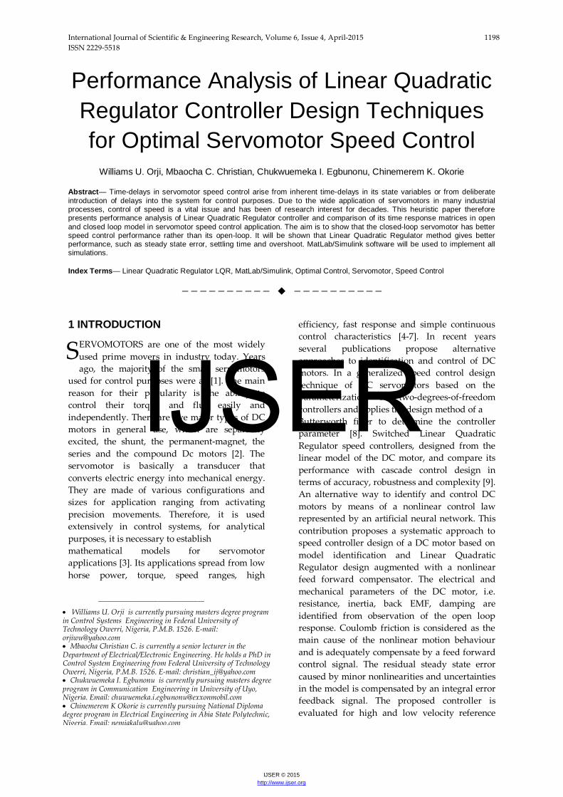
Below is the schematic diagram of servomotor for mathematical dynamics in Figure 1
The cause and effect relation with reference to Kirchhoff’s Law and the popular Isaac Newton’s 2nd Law of motion in Laplace Transform with other analytical cause and effect relations as below;
τ = Km i (1)
And
vemf = Km I (2)
𝐽 𝑑ɷ𝑑𝑡
= −𝐵ɷ+ Km (3)
Taking Laplace transform of equations (1) and (2), the transfer function of servomotor will be shown as;
𝑑𝑖𝑑𝑡= −
𝑅𝐿𝑖 −
Kb𝐿ɷ + 1
𝐿 eRa (4)
[3], [6], [7], [15]; See from the given parameters that, Kb=Kt, Hence K=Kb=Kt, thus with reference to equation (4), the transfer function of servomotor for speed control is derived considering the Laplace transform of equations above; We show below the state space of the system required to design Linear Quadratic Regulator controller. The linear-time-invariant is given generally as;
ẋ(t)=Ax(t) + Bu(t) (5)
y(t)=Cx(t)+Du(t) (6)
Where
A is an n×n state matrix
B is an n×r input matrix
C is m×n output matrix
D is an m×r matrix
x(t) is an n-state vector
u(t) is a r-control vector
The state space representation of speed control is given as;
𝑑𝑑𝑡� 𝑖ɷ� = �
−𝑅𝐿 − Kb
𝐿𝐾m𝐽
− 𝐵𝐽
� � 𝑖ɷ�+�1𝐿𝑎
0�ei (7)
y=[0 1] � 𝑖ɷ�+ [0] ei (8)
Fig. 1 DC Servomotor Circuit Diagram [3]
Parameters used are described below in Table I.
TABLE 1 PARAMETERS FOR DC SERVOMOTOR MODELLING
Parameters Values Armature Resistance, Ra 1.0Ω
Armature Inductance, La 0.05H
Moment of Inertia, J 0.01Kgm2/s2
Viscous Friction Coefficient, B 0.00003Nms
Back emf Constant, Kb 0.023Vs/rad
Torque Factor Constant, Km 0.023Nm/A
IJSER
International Journal of Scientific & Engineering Research, Volume 6, Issue 4, April-2015 1200 ISSN 2229-5518
IJSER © 2015 http://www.ijser.org
From the State-Space representation to Transfer
Function realization state of art, equations (7)
and (8) can be transformed with the relation in
equation (9-10) below; to give equation (11);
G(s) = C(sI-A)-1B+D (9)
G(s) = C𝑎𝑑𝑗(𝑠𝐼−𝐴)𝐷𝑒𝑡(𝑠𝐼−𝐴)
.B+D (10)
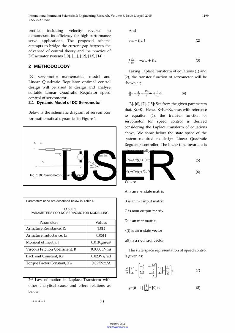
𝐺(𝑠)= 𝐾(𝑅𝑎+𝐿𝑎)(𝐽𝑆+𝐵)+𝐾2
(11)
Hence, the block diagram for speed control of servomotor is as shown below;
MatLab M-File will be used to derive equations for the servomotor speed control from the above continuous transfer function and state-space equations with reference to values in Table I. It is vital to transform continuous state space of the servomotor into discrete state space to enable Linear Quadratic Regulator controller design and implementation. This conversion is done in MatLab M-File using the command ‘‘[A, B] = c2d(Ac, Bc, Ts)’’ where TS represents time sampling for the servomotor.
2.2 Linear Quadratic Regulator
Linear Quadratic Regulator design technique is used in modern optimal control theory and has
been widely used in many control application. The standard theory of the optimal control is represented in [9]. Under the assumption that all state variables are available for feedback, the Linear Quadratic Regulator controller design method starts with a defined set of states which are to be controlled. In general, a linear-time-invariant system can be represented as seen in equation (7) above. The Linear Quadratic Regulator controller design is a method of reducing the performance to a reduced value. The minimization of it is just to the end of achieving acceptable performance of the system. The Linear Quadratic Regulator provides an optimal control law for a linear time invariant system with a quadratic performance index, [16] the continues form is as;
F(x, t) =minu∫ ℎ(𝒙,𝒖)𝑑𝑡 𝑡1𝑡0 (10)
Where over the time interval t0 to t1,
F(x, t0) = f(x(0)), f(x, t1) = 0 (11)
Reference to equation (7), a Hamilton-Jacob equation may be expressed as [16];
𝜕𝑓𝜕𝑡
= ─minu[h(x, u) (𝜕𝑓𝜕𝑥
)P
T g(x, u)] (12)
For a linear time invariant servomotor as in equations (6-7). If it is a quadratic performance index,
J = ∫ 𝑡1𝑡0 (𝒙P
TQx + uTRu)dt (13)
Substituting (6) and (13) into (12),
𝜕𝑓𝜕𝑡
= ─minu[𝒙P
TQx + uTRu+(𝜕𝑓𝜕𝑥
)P
T (Ax+ Bu)]
(14)
Introducing, f=(x, t) =xTPx, we get lastly
xT𝝏𝑷𝝏𝒕
x= ─minu[𝒙P
TQx + uTRu+2xTP(Ax + Bu) ]
(15)
The optimal control law is thus;
uopt = −𝑹−𝟏𝑩𝑻𝑷𝒙 (16)
Fig. 2: Block diagram of servomotor speed control
IJSER
International Journal of Scientific & Engineering Research, Volume 6, Issue 4, April-2015 1201 ISSN 2229-5518
IJSER © 2015 http://www.ijser.org
uopt = −Kx (17)
K= 𝑹−𝟏𝑩𝑻𝑷 (18)
xTṖx = -xT(Q + 2PA – PBR-1BTP)x (19)
2𝐱𝐓𝑷𝑨𝒙 = 𝒙𝑻(𝑨𝑻𝑷+𝑷𝑨)𝑨 (20)
Ṗ = −𝐏𝐀− 𝐀𝐓𝑷− 𝑸 +𝑷𝑩𝑹−𝟏𝑩𝑻𝑷 (21)
(21) belongs to a class of non-linear differential equations known as the matrix Riccati equations. Kalman demonstrated that as integration in reverse time proceeds, the solutions of P(t) converge to constant values [17]. Should t1 be infinite, or far removed from t0, the matrix Riccati equations reduce to a set of simultaneous equation.
PA + ATP + Q – PBR-1BTP = 0 (22)
3 LINEAR QUADRATIC REGULATOR OF SERVOMOTOR
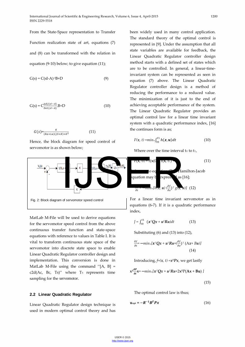
With reference to the diagram below, Linear Quadratic controller servomotor has been implemented [18].
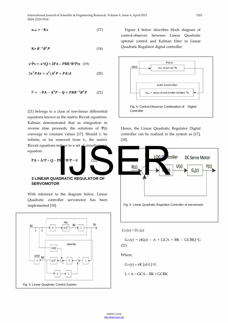
Figure 4 below describes block diagram of control-observer between Linear Quadratic optimal control and Kalman filter in Linear Quadratic Regulator digital controller.
Hence, the Linear Quadratic Regulator Digital controller can be realized in the system as [17], [18].
GD(z) = Dce(z)
GD(z) = zK[zI – A + GCA + BK – GCBK]-1G (21)
Where,
GD(z) = zK [zI-L]-1G
L = A – GCA – BK + GCBK
Fig. 4: Control-Observer Combination of Digital Controller
Fig. 5: Linear Quadratic Regulator Controller of servomotor
Fig. 3: Linear Quadratic Control System
IJSER
International Journal of Scientific & Engineering Research, Volume 6, Issue 4, April-2015 1202 ISSN 2229-5518
IJSER © 2015 http://www.ijser.org
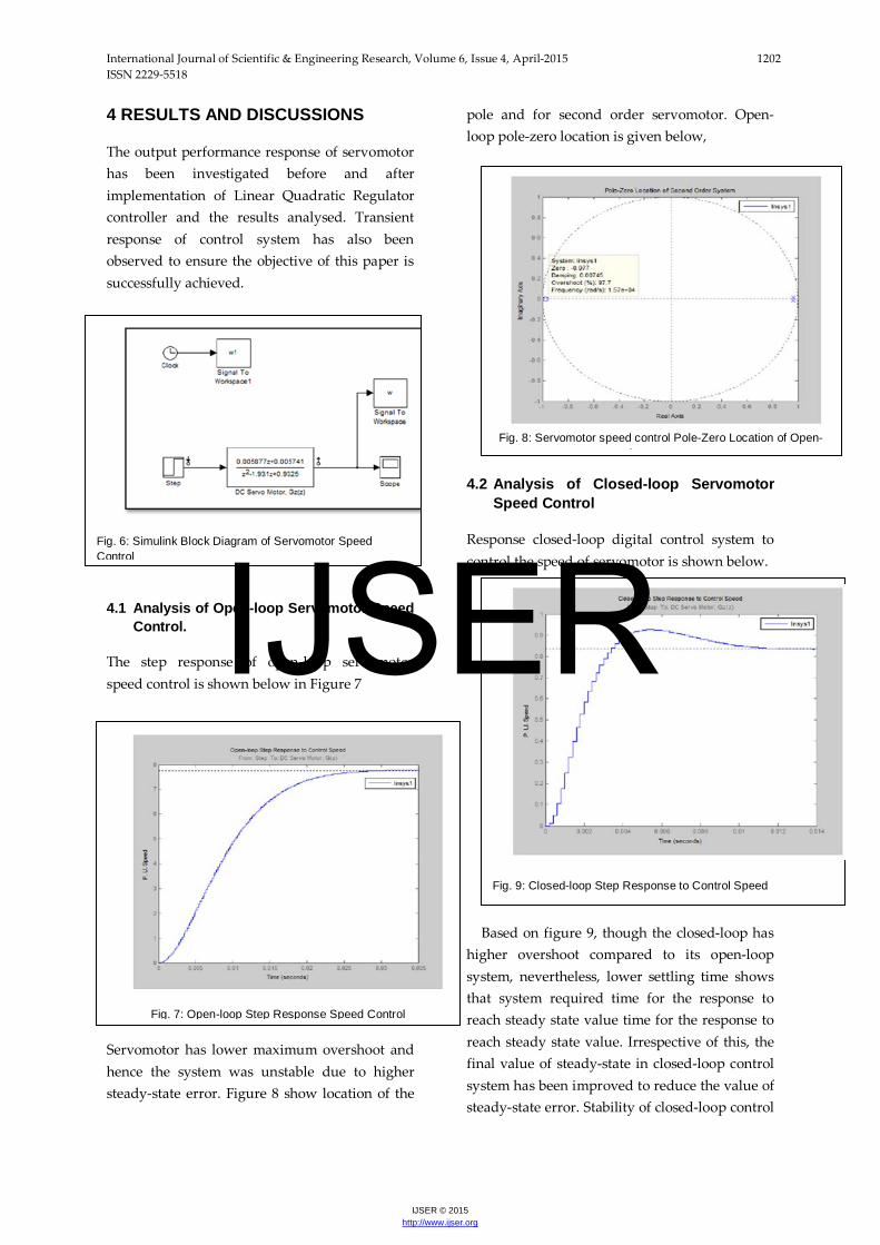
4 RESULTS AND DISCUSSIONS
The output performance response of servomotor has been investigated before and after implementation of Linear Quadratic Regulator controller and the results analysed. Transient response of control system has also been observed to ensure the objective of this paper is successfully achieved.
4.1 Analysis of Open-loop Servomotor Speed Control.
The step response of open-loop servomotor speed control is shown below in Figure 7
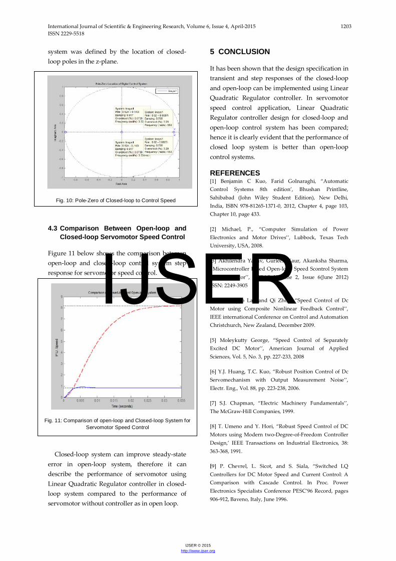
Servomotor has lower maximum overshoot and hence the system was unstable due to higher steady-state error. Figure 8 show location of the
pole and for second order servomotor. Open-loop pole-zero location is given below,
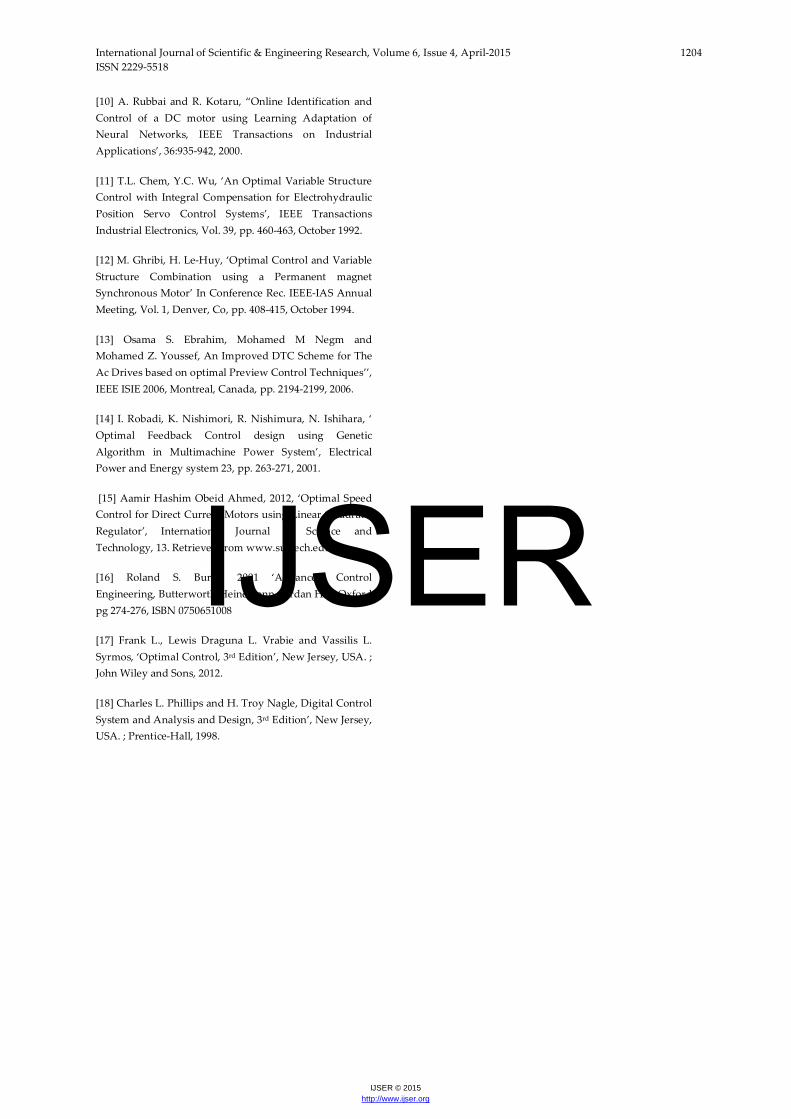
4.2 Analysis of Closed-loop Servomotor
Speed Control
Response closed-loop digital control system to control the speed of servomotor is shown below.
Based on figure 9, though the closed-loop has higher overshoot compared to its open-loop system, nevertheless, lower settling time shows that system required time for the response to reach steady state value time for the response to reach steady state value. Irrespective of this, the final value of steady-state in closed-loop control system has been improved to reduce the value of steady-state error. Stability of closed-loop control
Fig. 6: Simulink Block Diagram of Servomotor Speed Control
Fig. 9: Closed-loop Step Response to Control Speed
Fig. 8: Servomotor speed control Pole-Zero Location of Open-
l t
Fig. 7: Open-loop Step Response Speed Control
IJSER
International Journal of Scientific & Engineering Research, Volume 6, Issue 4, April-2015 1203 ISSN 2229-5518
IJSER © 2015 http://www.ijser.org
system was defined by the location of closed-loop poles in the z-plane.
4.3 Comparison Between Open-loop and Closed-loop Servomotor Speed Control
Figure 11 below shows the comparison between open-loop and closed-loop control system step response for servomotor speed control.
Closed-loop system can improve steady-state error in open-loop system, therefore it can describe the performance of servomotor using Linear Quadratic Regulator controller in closed-loop system compared to the performance of servomotor without controller as in open loop.
5 CONCLUSION
It has been shown that the design specification in transient and step responses of the closed-loop and open-loop can be implemented using Linear Quadratic Regulator controller. In servomotor speed control application, Linear Quadratic Regulator controller design for closed-loop and open-loop control system has been compared; hence it is clearly evident that the performance of closed loop system is better than open-loop control systems.
REFERENCES [1] Benjamin C Kuo, Farid Golnaraghi, “Automatic Control Systems 8th edition’, Bhushan Printline, Sahibabad (John Wiley Student Edition), New Delhi, India, ISBN 978-81265-1371-0, 2012, Chapter 4, page 103, Chapter 10, page 433.
[2] Michael, P., “Computer Simulation of Power Electronics and Motor Drives’’, Lubbock, Texas Tech University, USA, 2008.
[3] Akhilendra Yadav, Gurleen Kaur, Akanksha Sharma, “Microcontroller Based Open-loop Speed Scontrol System for DC Motor’’, IJREAS Volume 2, Issue 6(June 2012) ISSN: 2249-3905
[4] A. Weiyao Lan and Qi Zhou, “Speed Control of Dc Motor using Composite Nonlinear Feedback Control’’, IEEE international Conference on Control and Automation Christchurch, New Zealand, December 2009.
[5] Moleykutty George, “Speed Control of Separately Excited DC Motor’’, American Journal of Applied Sciences, Vol. 5, No. 3, pp. 227-233, 2008
[6] Y.J. Huang, T.C. Kuo, “Robust Position Control of Dc Servomechanism with Output Measurement Noise’’, Electr. Eng., Vol. 88, pp. 223-238, 2006.
[7] S.J. Chapman, “Electric Machinery Fundamentals’’, The McGraw-Hill Companies, 1999.
[8] T. Umeno and Y. Hori, “Robust Speed Control of DC Motors using Modern two-Degree-of-Freedom Controller Design,’ IEEE Transactions on Industrial Electronics, 38: 363-368, 1991.
[9] P. Chevrel, L. Sicot, and S. Siala, “Switched LQ Controllers for DC Motor Speed and Current Control: A Comparison with Cascade Control. In Proc. Power Electronics Specialists Conference PESC’96 Record, pages 906-912, Baveno, Italy, June 1996.
Fig. 10: Pole-Zero of Closed-loop to Control Speed
Fig. 11: Comparison of open-loop and Closed-loop System for Servomotor Speed Control
IJSER
International Journal of Scientific & Engineering Research, Volume 6, Issue 4, April-2015 1204 ISSN 2229-5518
IJSER © 2015 http://www.ijser.org
[10] A. Rubbai and R. Kotaru, “Online Identification and Control of a DC motor using Learning Adaptation of Neural Networks, IEEE Transactions on Industrial Applications’, 36:935-942, 2000.
[11] T.L. Chem, Y.C. Wu, ‘An Optimal Variable Structure Control with Integral Compensation for Electrohydraulic Position Servo Control Systems’, IEEE Transactions Industrial Electronics, Vol. 39, pp. 460-463, October 1992.
[12] M. Ghribi, H. Le-Huy, ‘Optimal Control and Variable Structure Combination using a Permanent magnet Synchronous Motor’ In Conference Rec. IEEE-IAS Annual Meeting, Vol. 1, Denver, Co, pp. 408-415, October 1994.
[13] Osama S. Ebrahim, Mohamed M Negm and Mohamed Z. Youssef, An Improved DTC Scheme for The Ac Drives based on optimal Preview Control Techniques’’, IEEE ISIE 2006, Montreal, Canada, pp. 2194-2199, 2006.
[14] I. Robadi, K. Nishimori, R. Nishimura, N. Ishihara, ‘ Optimal Feedback Control design using Genetic Algorithm in Multimachine Power System’, Electrical Power and Energy system 23, pp. 263-271, 2001.
[15] Aamir Hashim Obeid Ahmed, 2012, ‘Optimal Speed Control for Direct Current Motors using Linear Quadratic Regulator’, International Journal of Science and Technology, 13. Retrieved from www.sustech.edu
[16] Roland S. Burns, 2001 ‘Advanced Control Engineering, Butterworth Heinemann, Jordan Hill, Oxford pg 274-276, ISBN 0750651008
[17] Frank L., Lewis Draguna L. Vrabie and Vassilis L. Syrmos, ‘Optimal Control, 3rd Edition’, New Jersey, USA. ; John Wiley and Sons, 2012.
[18] Charles L. Phillips and H. Troy Nagle, Digital Control System and Analysis and Design, 3rd Edition’, New Jersey, USA. ; Prentice-Hall, 1998.
IJSER