faculty of manufacturing engineeringeprints.utem.edu.my/16811/1/design of linear quadratic...
TRANSCRIPT

Faculty of Manufacturing Engineering
DESIGN OF LINEAR QUADRATIC REGULATOR CONTROLLER WITH ADJUSTABLE GAIN FUNCTION FOR ROTARY INVERTED
PENDULUM SYSTEM
Tang Teng Fong
Master of Science in Manufacturing Engineering
2015

DESIGN OF LINEAR QUADRATIC REGULATOR CONTROLLER WITH ADJUSTABLE GAIN FUNCTION FOR ROTARY INVERTED PENDULUM
SYSTEM
TANG TENG FONG
A thesis submitted in fulfilment of the requirements for the degree of Master of Science
in Manufacturing Engineering
Faculty of Manufacturing Engineering
UNIVERSITI TEKNIKAL MALAYSIA MELAKA
2015

DECLARATION
I declare that this thesis entitled “Design of linear quadratic regulator controller with
adjustable gain function for rotary inverted pendulum system” is the result of my own
research except as cited in the references. The thesis has not been accepted for any degree
and is not concurrently submitted in candidature of any other degree.
Signature : ………………………………
Name : Tang Teng Fong
Date : ………………………………

APPROVAL
I hereby declare that I have read this thesis and in my opinion this thesis is sufficient in
terms of scope and quality for the award of Master of Science in Manufacturing
Engineering.
Signature : ……………………………………
Supervisor’s Name : Associate Prof. Dr. Zamberi bin Jamaludin
Date : ……………………………………

DEDICATION
To my beloved parents, Tang Chin Siang and Ong Geok Ee,
For taking good care and giving guidance in life and academic.
To my concerned sister, Tang Hoay Sean,
For giving moral support.
And also for those I love very much.

i
ABSTRACT
Design of controllers for non-linear systems has long drawn the attention of researchers especially in the fields of robotics, aerospace engineering and marine engineering. A classic example of a non-linear under-actuated control system is the balance control for a rotary inverted pendulum. Basically, the control approach for such system focusses on torque control of the servo-motor for the purpose of rotating the arm and stabilising the pendulum in its upright position at the shortest possible time. The aim of this research is to supplement and further enhance the control performance of a linear quadratic regulator (LQR) controller with focus on reduced response time and degree of oscillation of the pendulum with added robustness against input disturbance applied to the pendulum position and voltage to the motor. Initially, this thesis comprehensively analysed the LQR controller parameters based on minimal balance time of the pendulum. The LQR controller by itself produced high degree of oscillations, long balance time and poor robustness against input disturbance. As an enhancement over this approach, an adjustable gain was added to the existing LQR control structure. The results showed that for a 30° balancing control, the LQR controller with adjustable gain managed to reduce as much as 70% in the balance time and 98% in the degree of oscillation, while improved its robustness by producing faster balance time and lower oscillation upon excitation by input disturbance forces. In conclusion, the LQR controller with adjustable gain has significantly improved the control performance of the rotary inverted pendulum system.

ii
ABSTRAK
Reka bentuk pengawal untuk sistem tidak linear telah sekian lama menarik perhatian penyelidik-penyelidik terutamanya dalam bidang robotik, kejuruteraan aeroangkasa dan kejuruteraan marin. Satu contoh klasik sistem kawalan tak lelurus yang kurang pacu gerak, ialah kawalan imbangan untuk bandul terbalik berputar. Pada asasnya, kaedah kawalan sistem sebegini berfokus kepada kawalan tork pada motor servo bagi tujuan memutar lengan dan menstabilkan bandul dalam kedudukan tegak pada masa paling singkat yang mungkin. Tujuan penyelidikan ini ialah untuk menambah dan meningkatkan lagi prestasi pengawal pengatur linear kuadratik (LQR) dengan fokus kepada pengurangan masa tindak balas bandul dan darjah ayunan dengan peningkatan keteguhan terhadap gangguan input pada kedudukan bandul dan voltan kepada motor. Tesis ini pada awalnya menganalisa secara komprehensif parameter pengawal LQR berdasarkan masa minima imbang bandul. Pengawal LQR dengan sendirinya menghasilkan darjah ayunan yang tinggi, masa imbang yang panjang dan tahap keteguhan yang rendah terhadap gangguan input. Sebagai satu peningkatan atas pengawal ini, satu pekali boleh laras ditambah kepada struktur pengawal LQR sedia ada. Keputusan yang diperolehi untuk kawalan keseimbangan 30° menunjukkan yang pengawal LQR dengan pekali boleh laras telah menurunkan sehingga 70% masa imbang dan 98% darjah ayunan serta memperbaiki tahap keteguhan sistem dengan menghasilkan masa imabang yang lebih cepat dan darjah ayunan yang lebih rendah apabila terdedah kepada gangguan input. Secara kesimpulannya, pengawal LQR yang ditambah baik dengan pekali boleh laras telah memperbaiki secara jelas prestasi kawalan sistem bandul terbalik berputar ini.
iii
ACKNOWLEDGMENTS
Firstly, I am blessed by the Lord Jesus Christ with wisdom and knowledge throughout the
research. The Lord has also granted me patience and peace during the writing and times of
facing challenges. Thank you the Lord for granting the success in my academic career.
Next, I would like to thank my respective supervisor, Associate Prof. Dr. Zamberi bin
Jamaludin and co-supervisor, Dr. Muhamad Arfauz bin Abdul Rahman from Faculty of
Manufacturing Engineering Universiti Teknikal Malaysia Melaka (UTeM). I am grateful
for having concerned and dedicated supervisors to guide and support me in this research.
Under their supervision, the research work is closely directed and monitored besides
abundance of encouragement and ideas towards the completion of this thesis.
Particularly, I would like to express my gratitude to my father, Tang Chin Siang and dear
mother, Ong Geok Ee who ensure my good health and continuous moral support as well as
advice. Moreover, special thanks to my close friend, Miss Tan Teng Teng, who shared my
happiness and sadness as well as knowledge throughout the journey of research.
Lastly, a special thanks to my research group members, Mr. Chiew Tsung Heng, Ir. Dr.
Lokman Abdullah, Mr. Jailani bin Jamaludin and Madam Nur Aidawati binti Rafan, who
willing to spend their precious times in sharing their knowledge and information about the
research with me.

iv
TABLE OF CONTENTS
PAGE DECLARATION APPROVAL DEDICATION ABSTRACT i ABSTRAK ii ACKNOWLEDGEMENTS iii TABLE OF CONTENTS iv LIST OF TABLES vi LIST OF FIGURES vii LIST OF APPENDICES xi LIST OF ABBREVIATIONS xii LIST OF SYMBOLS xiv LIST OF PUBLICATIONS xviii CHAPTER 1. INTRODUCTION 1 1.1 Background 1 1.2 Problem Statement 2 1.3 Objectives 3 1.4 Scopes 3 1.5 Significance of Study 4 1.6 Outline of Thesis 5 2. LITERATURE REVIEW 6 2.1 Inverted Pendulum System 6 2.1.1 Linear Inverted Pendulum 7 2.1.2 Rotary Inverted Pendulum 9 2.2 Application of Inverted Pendulum System 10 2.3 Controller Design for Balance Control of Inverted Pendulum 12 2.3.1 Proportional Integrated Derivative Controller 13 2.3.2 Linear Quadratic Regulator Controller 14 2.3.3 Sliding Mode Controller 17 2.3.4 Fuzzy Logic Controller 18 2.4 Summary 20 3. EXPERIMENTAL SETUP AND SYSTEM IDENTIFICATION 22 3.1 Project Planning 22 3.2 Experimental Setup 24 3.3 System Identification and Modelling 26 3.3.1 Mathematical Model 28 3.3.1.1 Non-linear Mathematical Model 31 3.3.1.2 Linearization of Non-linear Mathematical
Model 32
3.3.1.3 State-space Model for the Pendulum in Upright Position
33

v
3.3.1.4 State-space Model for the Pendulum in Downward Position
35
3.3.2 Frequency Response Method 37 3.3.3 Validation of System Model 39 3.4 Summary 40 4. Controller Design 42 4.1 Introduction 42 4.2 Design of Linear Quadratic Regulator Controller 43 4.2.1 Numerical Analysis 46 4.3 Design of Linear Quadratic Regulator Controller with Adjustable
Gain Function 54
4.4 Summary 62 5. RESULT AND DISCUSSION 63 5.1 Analysis of Control Performance 63 5.2 Analysis of Control Performance with Applied Disturbance 67 5.2.1 Disturbance at Input Voltage 67 5.2.2 Input Disturbance at the Pendulum Position 74 5.3 Analysis of Tracking Control Performance 78 5.4 Summary 81 6. CONCLUSION AND FUTURE STUDY 83 6.1 Conclusion 83 6.2 Recommendation and Future Study 84 REFERENCES 86 APPENDICES 90
vi
LIST OF TABLES
TABLE TITLE PAGE
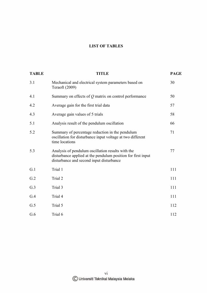
3.1 Mechanical and electrical system parameters based on Teraoft (2009)
30
4.1 Summary on effects of Q matrix on control performance 50
4.2 Average gain for the first trial data 57
4.3 Average gain values of 5 trials 58
5.1 Analysis result of the pendulum oscillation 66
5.2 Summary of percentage reduction in the pendulum oscillation for disturbance input voltage at two different time locations
71
5.3 Analysis of pendulum oscillation results with the disturbance applied at the pendulum position for first input disturbance and second input disturbance
77
G.1 Trial 1 111
G.2 Trial 2 111
G.3 Trial 3 111
G.4 Trial 4 111
G.5 Trial 5 112
G.6 Trial 6 112

vii
LIST OF FIGURES
FIGURE TITLE PAGE
2.1 Simplified linear inverted pendulum 8
2.2 Simplified rotary inverted pendulum 9
2.3 The Segway personal transporter 11
2.4 HRP-4C Humanoid 11
2.5 Transporting the loads by using a crane 11
3.1 Flow chart of overall methodology 22
3.2 Experimental setup of rotary inverted pendulum 24
3.3 System setup of EMECS 25
3.4 Rotary inverted pendulum from TeraSoft 25
3.5 Flow chart of the system identification and modelling 27
3.6 Free body diagram of a rotary inverted pendulum 29
3.7 Schematic diagram of a rotary inverted pendulum when the pendulum is in the upright position
32
3.8 Schematic diagram of a rotary inverted pendulum when the pendulum is in the downward position
35
3.9 Simulink diagram for FRF measurement 38
3.10 Comparison between system FRF, parametric model and mathematical model in frequency response
39
4.1 Flow chart of the controller design 42
4.2 Balance interval of pendulum for the analysis of the Q parameter
45
4.3 The LQR simulation control scheme 46
viii
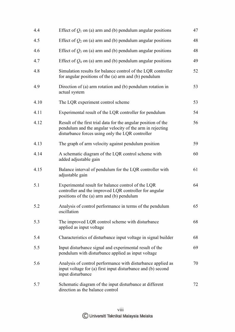
4.4 Effect of Q1 on (a) arm and (b) pendulum angular positions 47
4.5 Effect of Q2 on (a) arm and (b) pendulum angular positions 48
4.6 Effect of Q3 on (a) arm and (b) pendulum angular positions 48
4.7 Effect of Q4 on (a) arm and (b) pendulum angular positions 49
4.8 Simulation results for balance control of the LQR controller for angular positions of the (a) arm and (b) pendulum
52
4.9 Direction of (a) arm rotation and (b) pendulum rotation in actual system
53
4.10 The LQR experiment control scheme 53
4.11 Experimental result of the LQR controller for pendulum 54
4.12 Result of the first trial data for the angular position of the pendulum and the angular velocity of the arm in rejecting disturbance forces using only the LQR controller
56
4.13 The graph of arm velocity against pendulum position 59
4.14 A schematic diagram of the LQR control scheme with added adjustable gain
60
4.15 Balance interval of pendulum for the LQR controller with adjustable gain
61
5.1 Experimental result for balance control of the LQR controller and the improved LQR controller for angular positions of the (a) arm and (b) pendulum
64
5.2 Analysis of control performance in terms of the pendulum oscillation
65
5.3 The improved LQR control scheme with disturbance applied as input voltage
68
5.4 Characteristics of disturbance input voltage in signal builder 68
5.5 Input disturbance signal and experimental result of the pendulum with disturbance applied as input voltage
69
5.6 Analysis of control performance with disturbance applied as input voltage for (a) first input disturbance and (b) second input disturbance
70
5.7 Schematic diagram of the input disturbance at different direction as the balance control
72

ix
5.8 Schematic diagram of the input disturbance in the same direction as the balance control
73
5.9 The improved LQR control scheme with disturbance applied at the pendulum position
74
5.10 Continuous disturbance signal passed at the pendulum position
75
5.11 Experimental results for the system with disturbance input applied at the pendulum position
75
5.12 Analysis of control performance with disturbance applied at the pendulum position for (a) first input disturbance and (b) second input disturbance
77
5.13 Step input signal and the improved LQR control scheme for tracking performance
79
5.14 Step input signal and the measured angular position of the arm with the step input
80
5.15 Measured angular position of the pendulum with the input step function
80
E.1 Rotary inverted pendulum system 102
E.2 3-1 102
E.3 3-2 103
E.4 3-3 103
E.5 3-4 103
E.6 4-1 104
E.7 4-2 104
E.8 4-3 104
F.1 The LQR experiment Simulink diagram 105
F.2 The LQR with adjustable gain experiment Simulink diagram
105
F.3 Simulink diagram for the disturbance applied as input voltage
106
F.4 Simulink diagram for the disturbance applied at the pendulum position
106

x
F.5 Simulink diagram for the tracking performance 107
G.1 Trial 1 108
G.2 Trial 2 109
G.3 Trial 3 109
G.4 Trial 4 110
G.5 Trial 5 110

xi
LIST OF APPENDICES
APPENDIX TITLE PAGE
A Determination of Linear Mathematical Model for the Pendulum in Upright Position
90
B Determination of State-space Model for the Pendulum in Upright Position
94
C Determination of Linear Mathematical Model for the Pendulum in Downward Position
96
D Determination of State-space Model for the Pendulum in Downward Position
100
E Rotary Inverted Pendulum System Scheme 102
F Simulink Block Diagrams of the LQR Control Scheme and the LQR with Adjustable Gain Function Control Scheme
105
G Determination of the Adjustable Gain Function 108

xii
LIST OF ABBREVIATIONS
AC/DC - Analogue converter/ digital converter
ACO - Ant colony optimization
ADC - Analogue-to-digital converter
D - Derivative
DAC - Digital-to-analogue converter
DAQ - Data acquisition system
DC - Direct current
DOF - Degree of freedom
EMECS - Electro-Mechanical Engineering Control System
FL - Fuzzy logic
FRF - Frequency response function
FSF - Full state feedback
GA - Genetic algorithm
GPIO - General-purpose input/output
I - Integral
LIP - Linear inverted pendulum
LQR - Linear quadratic regulator
P - Proportional
PC - Personal computer
PID - Proportional integrated derivative
PWM - Pulse-width modulation

xiii
RIP - Rotary inverted pendulum
SMC - Sliding mode controller
TORA - Translational oscillations with a rotational actuator
VSC - Variable structure control
VTOL - Vertical take-off and landing

xiv
LIST OF SYMBOLS
Mathematical Symbol:
- Approximately equivalent
- Infinity
Ω - Ohm
xf
- Partial derivative
π - Pi
- Plus or minus
- - Minus
% - Percentage
/ - Divide
+ - Plus
= - Equal
A - Ampere
cos - Cosine
dB - Decibel
f(x) - Function notation
G - Gravitational acceleration
Hz - Hertz
kg - Kilogram
m - Meter
N - Newton

xv
o - Degree
rad - Radian
s - Second
sin - Sine
t - Time
T - Transpose
V - Volt
System Model Symbol:
1θ - Angular acceleration of arm
2θ - Angular acceleration of pendulum
2α - Angular acceleration of pendulum (downward position)
1θ - Angular position of arm
2θ - Angular position of pendulum
2α - Angular position of pendulum (downward position)
1θ - Angular velocity of arm
2θ - Angular velocity of pendulum
2α - Angular velocity of pendulum (downward position)
mR - Armature resistance
1τ - Control torque
e - Control voltage
1c - Distance to centre of arm mass
2c - Distance to centre of pendulum mass
1J - Inertia of arm

xvi
2J - Inertia of pendulum
1l - Length of arm
2l - Length of pendulum
1m - Mass of arm
2m - Mass of pendulum
bK - Motor back-emf constant
uK - Motor driver amplifier gain
tK - Motor torque constant
1C - Viscous friction co-efficient of arm
2C - Viscous friction co-efficient of pendulum
Control System Symbol:
x - Future state
A - System matrix
B - Control matrix or input matrix
C - Output matrix
D - Feed forward matrix
G(s) - Transfer function of system model
GPID(s) - Transfer function of PID controller
J - Quadratic performance index
Kd - Derivative gain (PID controller)
Kd - State-feedback gains (LQR controller)
Ki - Integral gain
m - Adjustable gain
Q - Diagonal weight matrix

xvii
R - Weight factor
S - Riccati solution
Ts - Sampling time
u - Input
u(t) - Input signal
x - Current state
y(t) - Output

xviii
LIST OF PUBLICATIONS
Journal:
1. Fong, T.T., Jamaludin, Z. and Abdullah, L., 2014. System Identification and
Modelling of Rotary Inverted Pendulum. International Journal of Advances in
Engineering & Technology (IJAET), 6(6), pp. 2342–2353.
Conference:
1. Fong, T.T., Jamaludin, Z., Hashim, A.Y.B. and Rahman, M.A.A., 2014. Design and
Analysis of Linear Quadratic Regulator for a Non-linear Positioning System. 3rd
International Conference on Design and Concurrent Engineering (iDECON), Melaka,
22nd – 23rd September 2014. [Accepted]

1
CHAPTER 1
INTRODUCTION
This chapter introduces the research work on control system design and
development for rotary inverted pendulum (RIP). Sections included in this chapter are the
background of the RIP system, problem statement, outlines of research, objectives, scopes,
and the content of this thesis. In addition, a segment on contribution to knowledge based
on the research work done is also included.
1.1 Background
Since the last few decades, control system design for non-linear and under-actuated
systems has generated great interest among researchers. These interests cover a wide
spectrum of applications that include control of a space booster rocket, satellite, an
automatic aircraft landing system, and stabilisation of a robot. Rotary inverted pendulum
(RIP) system is an example of a classical under-actuated system. The RIP consists of a
rigid rod called pendulum, which is rotating freely in the vertical plane. The vertical
pendulum is naturally unstable with the oscillation as it hangs downward at the equilibrium
point. A swing-up action using rotary actuation of a pivot arm in the horizontal plane by a
servo-motor would then result in the vertical pendulum achieving upright equilibrium point.
A robust and stable controller must be applied in order to control the torque of the servo-
motor for the purpose of rotating the arm and stabilising the pendulum in upright position.
The balancing control of a pendulum in the upright position is studied in this
research. Firstly, the system model was derived mathematically using Lagrange’s