pei-660 aib series 43-49 - farnell element14 · aib/gt series features simple and fast mating and...
TRANSCRIPT
43For price & delivery: 800-642-8750 • For tech support: 800-523-0727 • www.PeiGenesis.com Specifications subject to change.
▲
AIB
/AIB
C A
mph
enol In
dustrial Bayon
et/GT/A
CA
-B Series
AIB
/AIB
C A
mph
enol In
dustrial Bayon
et/GT/A
CA
-B Series
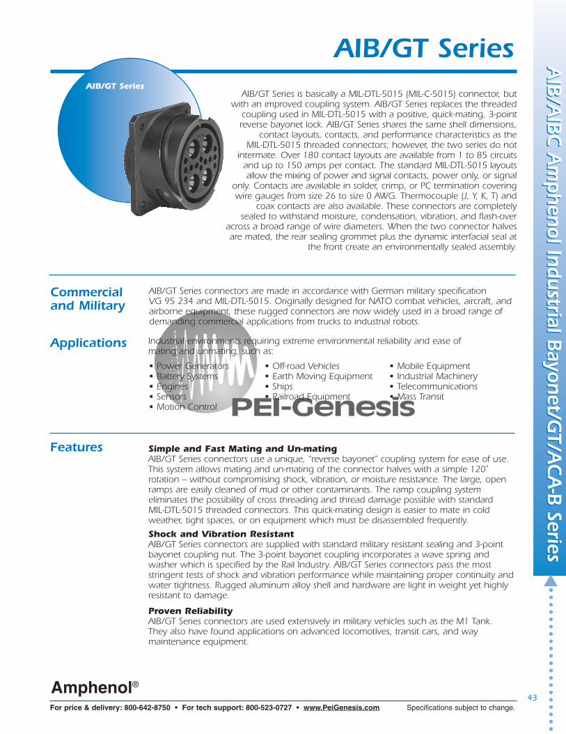
AIB/GT SeriesAIB/GT Series is basically a MIL-DTL-5015 (MIL-C-5015) connector, but
with an improved coupling system. AIB/GT Series replaces the threaded coupling used in MIL-DTL-5015 with a positive, quick-mating, 3-pointreverse bayonet lock. AIB/GT Series shares the same shell dimensions,
contact layouts, contacts, and performance characteristics as the MIL-DTL-5015 threaded connectors; however, the two series do not
intermate. Over 180 contact layouts are available from 1 to 85 circuitsand up to 150 amps per contact. The standard MIL-DTL-5015 layoutsallow the mixing of power and signal contacts, power only, or signal
only. Contacts are available in solder, crimp, or PC termination coveringwire gauges from size 26 to size 0 AWG. Thermocouple (J, Y, K, T) and
coax contacts are also available. These connectors are completely sealed to withstand moisture, condensation, vibration, and flash-over
across a broad range of wire diameters. When the two connector halves are mated, the rear sealing grommet plus the dynamic interfacial seal at
the front create an environmentally sealed assembly.
Commercialand Military
AIB/GT Series connectors are made in accordance with German military specification VG 95 234 and MIL-DTL-5015. Originally designed for NATO combat vehicles, aircraft, and airborne equipment, these rugged connectors are now widely used in a broad range ofdemanding commercial applications from trucks to industrial robots.
• Power Generators• Battery Systems• Engines• Sensors• Motion Control
• Off-road Vehicles• Earth Moving Equipment• Ships• Railroad Equipment
Applications
• Mobile Equipment• Industrial Machinery• Telecommunications• Mass Transit
Industrial environments requiring extreme environmental reliability and ease of mating and unmating, such as:
AIB/GT Series
Features Simple and Fast Mating and Un-matingAIB/GT Series connectors use a unique, “reverse bayonet” coupling system for ease of use. This system allows mating and un-mating of the connector halves with a simple 120˚ rotation – without compromising shock, vibration, or moisture resistance. The large, openramps are easily cleaned of mud or other contaminants. The ramp coupling system eliminates the possibility of cross threading and thread damage possible with standard MIL-DTL-5015 threaded connectors. This quick-mating design is easier to mate in cold weather, tight spaces, or on equipment which must be disassembled frequently.
Shock and Vibration ResistantAIB/GT Series connectors are supplied with standard military resistant sealing and 3-pointbayonet coupling nut. The 3-point bayonet coupling incorporates a wave spring and washer which is specified by the Rail Industry. AIB/GT Series connectors pass the most stringent tests of shock and vibration performance while maintaining proper continuity andwater tightness. Rugged aluminum alloy shell and hardware are light in weight yet highlyresistant to damage.
Proven ReliabilityAIB/GT Series connectors are used extensively in military vehicles such as the M1 Tank. They also have found applications on advanced locomotives, transit cars, and way maintenance equipment.
Amphenol®
44
▲
For price & delivery: 800-642-8750 • For tech support: 800-523-0727 • www.PeiGenesis.com Specifications subject to change.
Features Audible, Visual, and Tactile Confirmation of MatingAIB/GT Series connectors provide the user with three independent checks that the connectorhalves are mated. When the coupling nut is fully rotated, the three studs snap into the endof the ramps with a loud “click” (audible confirmation). At that same moment, the user canactually feel the bolts click into the grooves (tactile confirmation). Blue dots on the receptacleand on the coupling nut are aligned when the connector is properly mated (visual confirmation).
EnvironmentalThe sealing of this connector is not compromised by any of the operating conditions defined in MIL-DTL-5015. The connector is completely watertight when mated.
Broad Temperature RangeThese connectors will operate in temperatures from -67˚ to +257˚F (-55˚ to +125˚C). Hightemperature and zero halogen insulators are also available. Call for ordering information.
Wide Range of Wire Gauges and Current Carrying CapabilityUp to 150 amps with accommodations for wire gauges from size 26 up to size 0 AWG wire.
Wide Variety of ContactsHigh reliability screw machine contacts with silver or gold plating are available in sizes from20 through 0 to accommodate wire gauges from 26 to 0 AWG. Solder, Crimp, PC, Coax,and Thermocouple contacts are available.
AIB/GT Series connectors use rail industry standard crimp contacts which are completely interchangeable with other rail connectors such as Litton/Veam CIR series.
Intermateable and Intermountable with all VG 95 234 ConnectorsThe standard MIL-DTL-5015 layouts and dimensions ensure intermateability and intermountability with all connectors made in accordance with VG 95 234.
All AIB/GT Series connectors are intermountable with standard threaded MIL-DTL-5015 connectors, making it possible to upgrade without the need to change panel cutouts orclearances in most cases.
TechnicalSpecifications MATERIALS & FINISHES
Shell Aluminum alloy. (Shells can be grounded)
Plating Olive drab chromate coating over cadmium plating, black zinc cobalt, electroless nickel, green zinc, and black anodized
Contacts Copper alloy
Platings Hard silver plating or gold plating
Insulator* Neoprene
Seals Silicone, Neoprene, or Viton**
*Optional zero halogen and high temperature insulators are available. Call for information.**Viton is a registered trademark of DuPont DOW Elastomers
Amphenol®
AIB
/AIB
C A
mph
enol In
dustrial Bayon
et/GT/A
CA
-B Series
AIB
/AIB
C A
mph
enol In
dustrial Bayon
et/GT/A
CA
-B Series
45For price & delivery: 800-642-8750 • For tech support: 800-523-0727 • www.PeiGenesis.com Specifications subject to change.
▲
AIB
/AIB
C A
mph
enol In
dustrial Bayon
et/GT/A
CA
-B Series
AIB
/AIB
C A
mph
enol In
dustrial Bayon
et/GT/A
CA
-B Series
TechnicalSpecifications
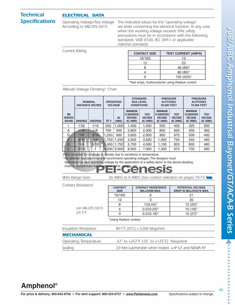
CONTACT SIZE TEST CURRENT (AMPS)
16/16S 13 12 23 8 46 (69)* 4 80 (80)* 0 150 (225)*
ELECTRICAL DATA
Operating Voltage/Test Voltage The indicated values for the “operating voltage”According to MIL-DTL-5015 are limits concerning the electrical function. In any case,
when the working voltage exceeds 50V, safety precautions must be in accordance with the following standards: VDE 0100, IEC 309-1 or applicable national standards
Current Rating
Altitude Voltage Derating* Chart
per MIL-DTL-5015p3.5.4
CONTACT CONTACT RESISTANCE POTENTIAL VOLTAGESIZE MILLIOHM MAX. DROP IN MILLIVOLTS MAX.
16/16S 6 2112 3 20 8 1/(0.44)* 12 (20)* 4 0.5/(0.23)* 10 (18)*0 0.2/(0.18)* 10 (27)*
Insulation Resistance @77˚F (25˚C) > 5,000 Megohms
†Not corrected for changes in density due to variations in temperature* No attempt has been made to recommend operating voltages. The designer must
determine his own operating voltage by the application of a safety factor to the above deratingchart to compensate for circuit transients, surges, etc.
Amphenol®
Wire Range Sizes 26 AWG to 0 AWG (See contact selection on pages 70-73
Contact Resistance
MSSERVICERATING AIRSPACE CREEPAGE
MINIMUMFLASHOVER
VOLTAGEAC (RMS)
TESTVOLTAGEAC (RMS)
MINIMUMFLASHOVER
VOLTAGEAC (RMS)
TESTVOLTAGEAC (RMS)
MINIMUMFLASHOVER
VOLTAGEAC (RMS)
TESTVOLTAGEAC (RMS)
I 1/32 1/16 250 1,000 1,400 1,000 550 400 325 260A 1/16 1/8 700 500 2,800 2,000 800 600 450 360D 1/8 3/16 1,250 900 3,600 2,800 900 675 500 400E 3/16 1/4 1,750 1,250 4,500 3,500 1,000 750 550 440B 1/4 5/16 2,450 1,750 5,700 4,500 1,100 825 600 480C 5/16 1 4,200 3,000 8,500 7,000 1,300 975 700 560
NOMINALDISTANCE INCHES
STANDARD SEA LEVEL
CONDITIONS
PRESSURE ALTITUDE†50,000 FEET
PRESSURE ALTITUDE†70,000 FEET
DC VAC
(RMS)
OPERATINGVOLTAGE
MECHANICAL
Operating Temperature -67˚ to +257˚F (-55˚ to +125˚C) Neoprene
Sealing 33 feet submersible when mated. ≈ IP 67 and NEMA 4P
*Using Radsok contact
*Test amps, multiconductor using Radsok contact
➥

46
▲
For price & delivery: 800-642-8750 • For tech support: 800-523-0727 • www.PeiGenesis.com Specifications subject to change.
TechnicalSpecifications
SEALING RANGE
16 .090 - .118 2.3 - 3.0 12 .126 - .177 3.2 - 4.58 .150 - .256 3.8 - 6.5 4 .279 - .366 7.1 - 9.30 .394 - .539 10.0 - 13.7
CONTACTSIZE
Wire Sealing Range The connector is designed for individual wire sealing.Sealing of an outer cable jacket on multiconductorcables must be accomplished with an appropriate endbell. Sealing is only guaranteed if wires according to MIL-W-5086 or within the listed ranges are used.
INCHES (mm)
Amphenol®
Insulation Strip Lengths See Contact Selection Chart on page 70
Mating Life 2,000 cycles minimum (commercial) 500 cycles minimum (military)
Salt Spray Olive drab chromate over cadmium - 500 hoursNon-conductive black zinc - 200 hoursConductive black zinc - 48 hoursBlack anodized - 500+ hoursElectroless nickel - 48 hours
Heat Neoprene 257˚F (+125˚C); Low Smoke Zero Halogen (LSZH)347˚F (+175˚C); Viton 392˚F (+200˚C)
Chemical Resistance Diesel Fuel 48-hour intermittent spray for eachJP-4 chemical with no deterioration, Hydraulic Fluid followed by Contact Retention (CR),Gasoline Insulation Resistance (IR), Dielectric
Withstanding Voltage tests (DWV)
Corrosion Resistance Olive Drab Cadmium Plated48 Hrs per MIL-DTL-5015 (3.17/4.6.13)
Fluid Immersion Hydraulic Fluid 20 hours per MIL-DTL-5015 (3.19/4.6.15)Lubrication Oil 20 hours per MIL-DTL-5015 (3.19/4.6.15)
Vibration per MIL-STD-810C, method 516.2, procedure VIII1.0 g peak from 5 to 25 Hz.030” double amplitude from 25 to 57 Hz5g peak from 57 to 500 Hz
Basic Shock Per MIL-STD-810C, method 516.2, procedure Ipulse at half sine wave of 30g for 11 seconds
Gun fire Shock Per MIL-STD-810C, method 516.2, procedure IVpulse at half sine wave of 100g for 1.5 seconds
Ballistic Shock Per MIL-STD-810C, method 516.2, procedure IVpulse at half sine wave of 200g for .5 seconds
Contact Type Solder, Crimp, PC, Coax, or Thermocouple. Hard silver or gold plating.
Contact Insertion From rear with simple hand tool. Removable, 5 cycles minimum.
Contact Retention Pin and socket contacts are designed to resist severe vibration and repeated connection & disconnection.Contact retention and separation is tested accordingto MIL-DTL-5015 (3.10/4.6.6.3)
CONTACT RETENTIONSIZE FORCE MIN.
16 1012 158 204 200 25
➥
AIB
/AIB
C A
mph
enol In
dustrial Bayon
et/GT/A
CA
-B Series
AIB
/AIB
C A
mph
enol In
dustrial Bayon
et/GT/A
CA
-B Series

THERMOCOUPLE CODESMATERIAL COLOR CODE CODE
Iron Black IRConstantan Yellow CON
Copper Alloy – CuChromel White CHAlumel Green AL
10SL 2614S 4416 50
16S 5018 5520 6522 8524 9028 11432 12036 15340 170
47For price & delivery: 800-642-8750 • For tech support: 800-523-0727 • www.PeiGenesis.com Specifications subject to change.
▲
AIB
/AIB
C A
mph
enol In
dustrial Bayon
et/GT/A
CA
-B Series
AIB
/AIB
C A
mph
enol In
dustrial Bayon
et/GT/A
CA
-B Series
SIZE IN./LB. MAX.
AIB/GT SeriesHow to Order
The next page contains a pictograph which portrays all of the standard possibilities for AIB/GT Series connectors. Follow the nine steps to create a description of the connector best suited to your application. This is not an Amphenol part number, butdoes give you a convenient way to select your connector. Call us with the descriptionfor a valid Amphenol part number. If you prefer to select the Amphenol part number,see the How-To-Order Guide on pages 94-95.
Many options not shown are available. Call us if your needs are not met by theoptions on the next page.
pin contact
insulator forpin contacts
bayonetramp
receptacleshell
bayonet pin
bayonetcoupling nut
ferrule (sleeve)
endbell
insulator for socket contact
stainlesssteel stud(optional) plug shell
AIB/GT SeriesCross-Section
TechnicalSpecifications
sealingring
wave spring
individualwire sealing
grommet
socketcontact
Amphenol®
Number of Circuits 1 to 85
Polarization Key and keyway plus three point bayonet with optional rotational polarization. See pages 59-69.
Rear Accessories Maximum Torque
endbello-ring
skid washer
Color code is identified by small dot onwire well end of contact.
Approvals/Agency Listing UL File# E115497
➥
➥
Thermocouple Types: J = Iron-Constantan
K = Alumel-ChromelT = Copper-Constantan E = Chromel-Constantan

48
▲
For price & delivery: 800-642-8750 • For tech support: 800-523-0727 • www.PeiGenesis.com Specifications subject to change.
Front Box MountNo AccessoryThreads
Plugs Receptacles▼
➤6
420
70
2
30
0
TB
1
Follow these 9 steps to create your part number. . .
STEP 1 STEP 2Select Shell Style, Plug or ReceptacleSelect
Connector Type
▼
▼
▼AIB
➤
➤mates with
➤mates with➤
ShellStyle
CableClamp/Heat
ShrinkBoot
EndbellsConnectorType
Standard(Most Popular)
Rubber Covered
mates with6HD
Heavy Duty
Cable Mountwith AccessoryThreads
Rear Wall Mountwith AccessoryThreads(Most Popular)
Front Wall Mountwith AccessoryThreads
Front Box Mountwith Rear Accessory Threads
Rear MountJam Nut with AccessoryThreads
Thru Bulkhead
* See pages 94-95 for Amphenol order codes.
Create your part number using these nine steps
(example)
Layout1 2 3 4 5 6 7 8 9
Contact Rotation
6B
Box Mount
7
Rear MountJam Nut No AccessoryThreads
if omitting endbell,
enter - (dash)
AIBC
* AIBC is the commercial version of the AIB. It comes without wear pins in the receptacles and without wavesprings in the coupling nuts.
** Note: AIBC are fully intermateable with all reverse bayonet connectors.
➤
➤
Plating/Modification
ContactType
AIB – 472SWP24-28AF6HD
mates with➤
➤
➥
AIB
/AIB
C A
mph
enol In
dustrial Bayon
et/GT/A
CA
-B Series
AIB
/AIB
C A
mph
enol In
dustrial Bayon
et/GT/A
CA
-B Series
(if needed)

49
For price & delivery: 800-642-8750 • For tech support: 800-523-0727 • www.PeiGenesis.com Specifications subject to change.
▲
AIB
/AIB
C A
mph
enol In
dustrial Bayon
et/GT/A
CA
-B Series
AIB
/AIB
C A
mph
enol In
dustrial Bayon
et/GT/A
CA
-B Series
STEP 4
▼
➤
G
Choose Cable Clampsand/or Heat Shrink Boot
Choose EndbellsSTEP 3
Choose layoutSTEP 5
S = SolderC = Crimp*H = PC**0 = Less contacts
L
T
F
(if applicable)
No Clamp
Long Extender
Internal thread version
External thread version
➤
See pages 50-69.
➤
Conduit Metal➤
➤
MS-3057-C
C
*Viton is a registered trademark of DuPont Dow Elastomers
Shielded Cable/Heat Shrink
STEP 9Choose Platings/Modifications
▼
P = PinS = SocketPS = Style TB only
STEP 6Choose Contact
STEP 7Choose Rotation
▼
See pages 59-69.(omit for normal)
STEP 8Choose Contact Type
* When using a “C” in part number, the connector is supplied with the standard sizecrimp contacts for its layout. Bolded part number on pages 70-73 indicate crimpcontacts. If reduced or enlarged crimp contactsare required, specify contact type 0 (less contacts) and order contacts separately.
** See page 75 for post diameters and lengths.
▼
P
Low Cost Gland Seal
Gland Seal
Potting * Potting Compoundsee page 261
90º
Standard Extender
▼
WXYZ
CONTACTS– B30 = Gold 30μ" Gold over Nickel– T = Thermocouple– RDS = RADSOK (Socket only) 8,4,0
Omit for silver contactsSHELLS
– 023 = Nickel (RoHS with crimp only)– 024 = Green Zinc Cobalt– 025 = Black Zinc Cobalt
(RoHS with crimp only)– 027 = Conductive Black
Zinc Cobalt (RoHS with crimp only)– G96= Black Anodized
Omit for olive drab chromate over cadmium– 116 = Less Pre-tinned Solder Cups– 472 = 116 & 025 mod codes (RoHS)– 548 = 116 & 023 mod codes (RoHS)
MATERIALSL = Low Smoke Zero HalogenV = High Temperature Viton®*
Shielded Cable Banding
MS-3057-A
9767Call with cable outside diameter.
A
RV
Heat Shrink
Standard Specials Call with NPT thread size, Sealtite conduit diameter, or cable outside diameter.
Conduit PlasticMesh Grip
▼▼
▼9767
➥
➥➥
➥
➥
➥
See pages 262-263.➥
Heat Shrink BootCall with cable outside diameter.See pages 258-260.

50
▲
For price & delivery: 800-642-8750 • For tech support: 800-523-0727 • www.PeiGenesis.com Specifications subject to change.
AIB
/AIB
C A
mph
enol In
dustrial Bayon
et/GT/A
CA
-B Series
AIB
/AIB
C A
mph
enol In
dustrial Bayon
et/GT/A
CA
-B Series
LAYOUT 20-23 22-1 22-8 22-11 24-9 28-7 32-5# OF CONTACTS 2-#8 2-#8 2-#12 2-#16 2-#4 2-#4 2-#0
SERIES ● ✚ ✦ ▼ ● ✦ ▼ ● ✚ ✦ ▼ ● ✚ ✦ ▼ ● ✚ ✦ ▼ ● ✜ ▼ ● ✚ ✦
SERVICE RATING A D E B A D D
1 CONTACT
LAYOUT 8S-1 10S-2 12S-4 12-5 14S-4 14-3 16S-3 16-2# OF CONTACTS 1-#16 1-#16 1-#16 1-#12 1-#16 1#8 1#16 1-#12
SERIES ✚ ✦ ✚ ✚ ✚ ✦ ● ✜ ✦ ✚ ● ✚ ● ✚ ▼
SERVICE RATING A A D D D A B E
LAYOUT 10SL-4* 12S-3* 14S-9* 16S-4 16-11 16-13 18-3 18-14 20-12# OF CONTACTS 2-#16 2-#16 2-#16 2-#16 2-#12 2*-#12 2-#12 1-#16; 1-#4 1-#16; 1-#4
SERIES ● ✚ ✦� ✚ ✦� ● ✚ ✦� ● ✚ ✦� ● ✚ ✦ ▼� ✖ ▼� ● ✚ ✦ ▼ ● ✜ ▼ ● ✜
SERVICE RATING A A A D A A D A A
3 CONTACTS
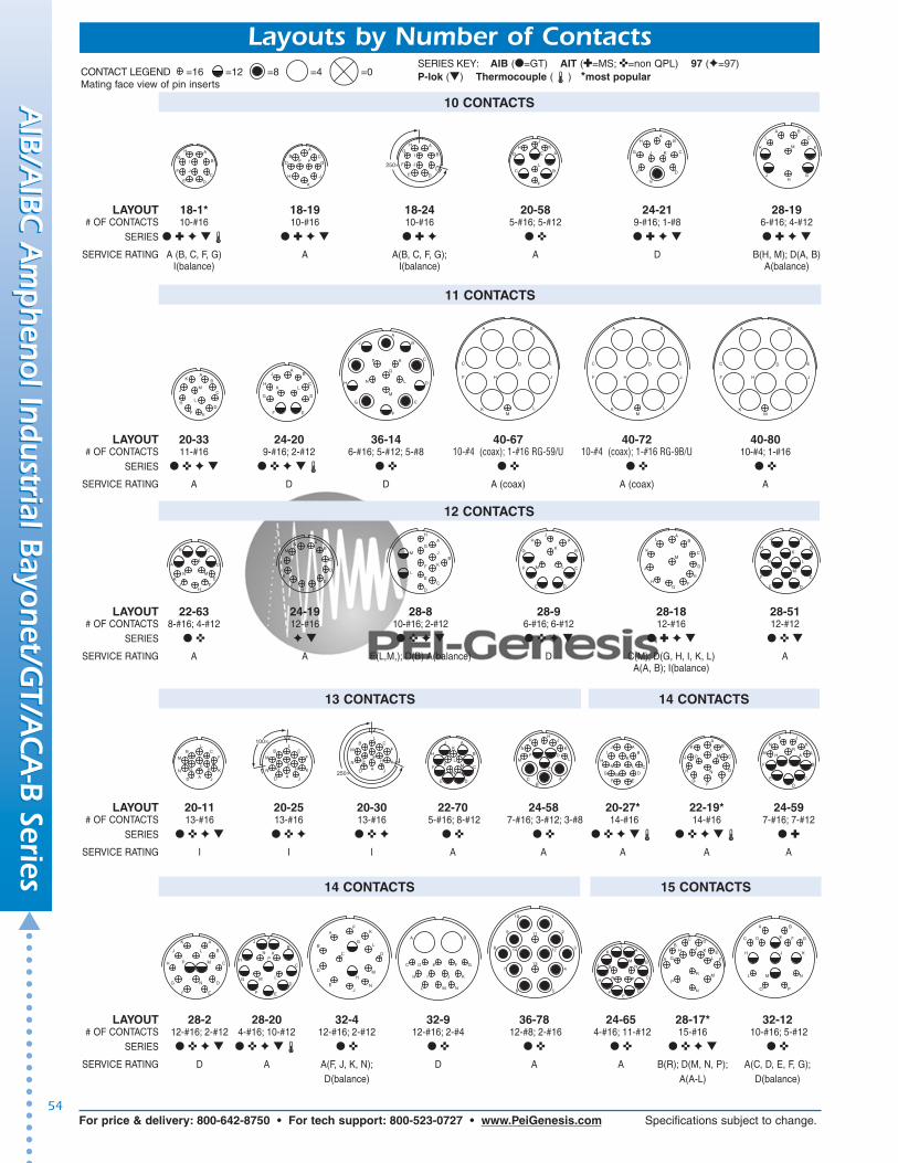
Layouts by Number of Contacts
2 CONTACTS
SERIES KEY: AIB (●=GT) AIT (✚=MS; ✜=non QPL) 97 (✦=97) P-lok (▼) Thermocouple (�) *most popular
LAYOUT 16-12 18-6 18-7 18-16 18-420 20-2 22-7 24-52# OF CONTACTS 1-#4 1-#4 1-#8 1-#12 1-#12 1-#0 1-#0 1-#12
SERIES ● ✚ ✦ ▼ ● ✚ ▼ ● ✜ ▼ ● ✜ ✦ ▼ ✦ ● ✚ ● ✚ ▼ ● ✜
SERVICE RATING A D B C 17 KVac D E 21 KVac24 KVdc 30 KVdc
A BB A
ABAB
A
B
AB
ABA
B
A
B
A
B
AB
ABAB
ABAB
A
B
LAYOUT 10SL-3 14S-1 14S-7 14S-12 16S-5 16S-6 16-7 16-10 18-5# OF CONTACTS 3-#16 3-#16 3-#16 3-#16 3-#16 3-#16 2-#16; 1-#8 3-#12 1-#16; 2-#12
SERIES ● ✚ ✦ ✚ ✦ ● ✚ ✦ ● ✚ ✦ ● ✚ ✦ ● ✜ ✦ ● ✚ ✦ ▼ ● ✚ ✦ ▼ ● ✚ ✦ ▼
SERVICE RATING A A A A A A A A D
LAYOUT 18-22 20-3 20-6 20-19 20-51 20-59 22-2 22-6# OF CONTACTS 3-#16 3-#12 3-#16 3-#8 3*-#8 3*-8 for #10 or 12 wire 3-#8 1-#16; 2-#8
SERIES ● ✜ ✦ ▼ ● ✜ ✦ ▼ ● ✜ ✦ ▼ ● ✚ ✦ ▼ ● ✜ ● ✜ ● ✚ ✦ ▼ ● ✚ ▼
SERVICE RATING D D D A A A D D
A B
CA
BC
A
BC
A
BC
A
B
C A
B
C
A
B
C
A
BC
AB
C
A
B
C
A
BC
A
B
C
A B
C
B
C A A
BC
100∞
A
B
CA
B
C
CONTACT LEGEND =16 =12 =8 =4 =0Mating face view of pin inserts

LAYOUT 40-57 40-66 40-86 14S-5* 16S-8* 18-11* 18-20# OF CONTACTS 4-#0 4-#0 (coax) 4-#0 (coax) 5-#16 5-#16 5-#12 5-#16
RG-63B/U RG-115A/USERIES ● ✜ ● ✜ ● ✜ ● ✚ ✦ ● ✚ ✦ ● ✚ ✦ ▼� ● ✚ ✦ ▼
SERVICE RATING E (coax) (coax) I A A A
LAYOUT 22-9 22-21 22-80 28-3 28-6 28-72 36-4# OF CONTACTS 3-#12 2-#16;1-#0 3*-#8 for #10 or 12 wire 3-#8 3*-#4 3-#4 (coax) RG-59A/U or RG-62A/U 3-#0
SERIES ● ✚ ✦ ▼ ● ✜ ▼ ● ✜ ● ✚ ✦ ▼ ● ✚ ✦ ▼ ● ✜ ● ✜
SERVICE RATING E A A E D (coax) D(A); A(B,C)
51For price & delivery: 800-642-8750 • For tech support: 800-523-0727 • www.PeiGenesis.com Specifications subject to change.
▲
AIB
/AIB
C A
mph
enol In
dustrial Bayon
et/GT/A
CA
-B Series
AIB
/AIB
C A
mph
enol In
dustrial Bayon
et/GT/A
CA
-B Series
4 CONTACTS
Layouts by Number of Contacts
3 CONTACTS (CONT.)
A
BC
A
B
C
A
BC
A
BC
A
BC
A
BC
A
BC
LAYOUT 12SL-844 14S-2* 14S-10 16-9 16-59 18-4* 18-10* 18-13 18-15# OF CONTACTS 4-#16 4-#16 4-#16 2-#16; 2-#12 4-#12 4-#16 4-#12 3-#12; 1-#8 4**-#12
SERIES ✦ ● ✚ ✦� ● ✚ ✦ ● ✚ ✦ ▼� ● ✜ ● ✚ ✦ ▼ ● ✚ ✦ ▼ ● ✚ ✧ ▼ ● ✚ ✦ �
SERVICE RATING I I I A A D A A A
A
BC
D
100∞A
BC
DA B
C D
A
BC
DA
BC
D
A
B
C
D A
B
C
D
A
B
C
D
LAYOUT 20-4* 20-20 20-24 22-4 22-10 22-22* 24-22* 32-17# OF CONTACTS 4-#12 3-#12; 1-#4 2-#16; 2-#8 2-#12; 2-#8 4-#16 4-#8 4-#8 4-#4
SERIES ● ✚ ✦ ▼� ● ✜ ▼ ● ✚ ✦ ▼ ● ✚ ✦ ▼ ● ✚ ✦ ▼� ● ✚ ✦ ▼ ● ✚ ✦ ▼ ● ✚ ✦
SERVICE RATING D A A A E A D D
A
B
D
C
A
B
C
DA
B
C
D
A
BC
DA
BC
D
A
BC
D
A
BC
D
A
BC
D
A
B
C
D
LAYOUT 32-58 36-5 36-51 36-64 36-65# OF CONTACTS 4-#4 (coax) 4-#0 2-#4; 2-#0 4-#0 (coax) RG-11/U; 4-#0 (coax) RG-59/U;
RG-161/U or RG-179/U RG-12/U or RG-13/U RG-62/U or RG-71/USERIES ● ✜ ● ✚ ✦ ● ✜ ● ✜ ● ✜
SERVICE RATING COAX A D (coax) (coax)
A
B
CD
A
B
C
D
A
B
C
D
1
2
3
4
1
2
3
4
1
2
3
4
LAYOUT 18-29 18-30 18-31 20-14 22-12 22-13 22-34 24-12# OF CONTACTS 5-#16 5-#16 5-#16 3-#12; 2-#8 3-#16; 2-#8 1-#16; 4-#12 2-#16; 3-#12 3-#12; 2-#4
SERIES ● ✜ ✦ ▼ ● ✚ ✦ ● ✚ ✦ ● ✚ ✦ ▼ ● ✜ ✦ ▼ ● ✜ ✦ ▼ ● ✚ ✦ ▼ ● ✚ ✦ ▼
SERVICE RATING A A A A D D(E) A(A,B,C,D) D A
A
BC
D
E110∞
A B
CD
E
A
B
C
D
EA
B
CD
E A
BC
DE
A
BC
DE
A
B
C
D
E
260∞
A B
CD
E
5 CONTACTS
A
B
C
D
E
A
BC
D
EA
BC
D
EA B
CD
E
A
B
C
D
A
B
C
D
CONTACT LEGEND =16 =12 =8 =4 =0Mating face view of pin inserts
SERIES KEY: AIB (●=GT) AIT (✚=MS; ✜=non QPL) 97 (✦=97) P-lok (▼) Thermocouple (�) *most popular

52
▲
For price & delivery: 800-642-8750 • For tech support: 800-523-0727 • www.PeiGenesis.com Specifications subject to change.
AIB
/AIB
C A
mph
enol In
dustrial Bayon
et/GT/A
CA
-B Series
AIB
/AIB
C A
mph
enol In
dustrial Bayon
et/GT/A
CA
-B Series
Layouts by Number of Contacts
5 CONTACTS (CONT.)
LAYOUT 24-17 24-51 24-53 24-79 28-5 32-1 32-2 32-79# OF CONTACTS 3-#16; 2-#12 5-#8 5-#8 5-#8 2-#16; 1-#12; 2-#4 3-#12; 2-#0 2-#16; 3-#4 1-#8; 4-#4
SERIES ● ✜ ▼ ● ✜ ● ✜ ● ✜ ● ✜ ▼ ● ✚ ● ✚ ● ✜
SERVICE RATING D B; E for AWG #10 or 12 wire A A D E(A); D(B, C, D, E) E DA; C; D for AN #18 wire
AB
C
D
E A
B
C
D
E A
B
C
D
E A
B
C
D
E
A
B
CD
E
A
B
CD
E
A
B
C
D
E
5 CONTACTS 6 CONTACTS
LAYOUT 40-5 40-75 14S-6* 18-12 20-8 20-17 20-22 20-66# OF CONTACTS 5-#0 4-#0; 1-#12 6-#16 6-#16 4-#16; 2-#8 1-#16; 5-#12 3-#16; 3-#8 1-#16
5-#12 for #10 wire
SERIES ● ✜ ● ✜ ● ✚ ✦� ● ✚ ▼� ● ✚ ✦ ▼ ● ✜ ✦ ▼ ● ✚ ✦ ▼ ● ✜
SERVICE RATING A E I A I A A A
A
BC
D
E
A
B
GC
N
F A
B
CD
E
A
B
C
D
EF
A
B
C
D
E F
A
B
C
D
E
F
A
BC
D
E
F
1
2
3
4
5
LAYOUT 22-5 22-15 22-24 28-22 28-82 36-3 36-6# OF CONTACTS 4-#16; 2-#12 1-#16; 5-#12 4-#16; 2-#12 3-#16; 3-#4 4-#12; 2-#8 3-#12; 3-#0 4-#0; 2-#0
SERIES ● ✚ ✦ ▼ ● ✚ ✦ ◆� ● ✜ ▼ ● ✜ ▼ ● ✜ ● ✜ ● ✚ ✦
SERVICE RATING D A(A, B, C, E, F); D(C, D, E) D D D AE(D) A(A, B, F)
A
BC
D
E
F
A
B
CD
E
F
1 23
4 5
6
A
B
CD
E
F
A
B
C
D
E
F
1
2
34
5
6
A
B
E
F
CD
A
B
C
D
E
F
7 CONTACTS
LAYOUT 40-74 14SA7 16S-1* 18-9 18-17 20-15* 20-57# OF CONTACTS 4-#0 (coax) RG-9B/U or RG-214/U 7-#16 7-#16 5-#16; 2-#12 5-#16; 2-#12 7-#12 12 for #14 or 16 wire
1-#4 (coax) RG-62/U; 1-#12
SERIES ● ✜ ● ✜ ● ✚ ✦� ● ✚ ✦ ▼� ● ✚ ✦ ▼ ● ✚ ✦ ▼� ● ✜
SERVICE RATING A A A I I A A
A
F
ED
C
BG
A
B
CD
E
F
G
A
B
C
D
E
F
G
A
B
CD
E G
F A
B
CD
E G
F
A
B
C
E
F
G
D
A
BCE
FG
D A
B
CD
E
FG
100∞
A
B
C
D
E
F
G
LAYOUT 22-28 22-33 24-2 24-3 24-10 24-16 24-27# OF CONTACTS 7-#12 7-#16 7-#12 5-#16; 2-#12 7-#8 3-#16; 3-#12; 1-#8 7-#16
SERIES ● ✚ ✦ ▼ ● ✜ ● ✚ ✦ ▼ ● ✜ ▼ ● ✚ ✦ ▼ ● ✜ ✦ ▼ ● ✚ ▼ ✦
SERVICE RATING A D(A, B, C, D) D D A D(A, B, F, G) EA(E, F, G) A(C, D, E)
A
B
C
E
F
G
D
A
B
C
DE
F
A
B
C
D
E
FG
A
B
C
D
E
F
G
CONTACT LEGEND =16 =12 =8 =4 =0Mating face view of pin inserts
SERIES KEY: AIB (●=GT) AIT (✚=MS; ✜=non QPL) 97 (✦=97) P-lok (▼) Thermocouple (�) *most popular
A
B
CD
E
F
G

8 CONTACTS
LAYOUT 22-18 22-23 22-65 24-6 32-15 32-52 32-57# OF CONTACTS 8-#16 8-#12 12 for #14 or 16 wire 8-#12 6-#12; 2-#0 2-#0; 6-#12 2-#0 (coax) RG-7/U; 6-#12
SERIES ● ✚ ✦ ▼ ● ✚ ✦ ▼ � ● ✜ ● ✜ ✦ ▼ ● ✜ ● ✜ ● ✜
SERVICE RATING D(A, B, F, G, H); D(H); D(H); A(balance) D(A, G, H); D D (coax)A(C, D, E) A(balance) A(balance)
A B C
D E F
G
H
I
53For price & delivery: 800-642-8750 • For tech support: 800-523-0727 • www.PeiGenesis.com Specifications subject to change.
▲
AIB
/AIB
C A
mph
enol In
dustrial Bayon
et/GT/A
CA
-B Series
AIB
/AIB
C A
mph
enol In
dustrial Bayon
et/GT/A
CA
-B Series
Layouts by Number of Contacts
A
B
CD
E
FG
A
B
CD
E
FG
A
B
CD
E
FG
A
B
CD
E
F
G
A
B
C
D
E
F
G
A
B
CD
E
F
G
7 CONTACTS (CONT.)
LAYOUT 24-60 24-66 24-71 24-75 28-10 32-10 36-73# OF CONTACTS 7-#8 or 12 wire 7-#12 5-#8 for #10 or 12 wire, 2-#8 for #16 wire; 3-#12; 2-#8; 3-#16; 2-#8; 2-#4 7-#4 (coax)
2-#8 5-#8 2-#4 RG-62B/USERIES ● ✜ ● ✜ ● ✜ ● ✜ ● ✚ ✦ ● ✜ ● ✜
SERVICE RATING I D A A D(G); A(balance) E(A, F); B(G); (coax)D(B, E); A(C, D)
A
B
C
D
E
F
G
A
B
C
D
E
F
G
1
2
34
5
6
7
A
B
C
DE
F
GH
A
B
C
DE
F
G H
A
B
C
DE
F
G
HA
B
CD
E
FG
H
LAYOUT 36-77 36-83 40-87 18-8* 20-7* 20-9 20-79# OF CONTACTS 7-#4 7-#4 (coax) RG-58/U 7-#4 7-#16; 1-#12 8-#16 7-#16; 1-#12 7-#16; 1-#12
SERIES ● ✜ ● ✜ ● ✜ ● ✚ ✦ ▼ ● ✚ ✦ ▼� ● ✜ ● ✜
SERVICE RATING D (coax) D A D(A, B, H, G); H = (D); H = D;A(C, D, E, F) A(balance) A(balance)
A
B
C
D
E
F
G
H
A
B
CD
E
FG
H
AB
C
D
E
F
G
H
A
B C
D E
F
G
H
90∞ A
B C
D E
F
G
H
A
B C
D E
F
G
H
A
B
CD
E
FG
H
LAYOUT 24-11 28-1 28-4 28-84 28AY 32-3 32-75# OF CONTACTS 6-#12; 3-#8 6-#12; 3-#8 7-#16; 2-#12 9-#8 5-#16; 4-#4 4-#16; 2-#12; 2-#4; 1-#0 7-#8 (coax); RG-180B/U
2-#12
SERIES ● ✚ ✦ ▼ ● ✚ ✦ ▼ ● ✜ ▼ ● ✜ ● ✜ ● ✚ ● ✜
SERVICE RATING A D(A, J, E); E(G, P, S); A A D D(8,9) (coax)A(balance) D(balance)
A B
C
DEF
G
H
J
A B
C DP
S
E FG
A
B
C
DE
F
G
H
I
AB C
D E F
G H
J
AB
C
D E F
G
H
J
1
2
3
4
5
6 7
8 9
A
B
CD
E
F
G
LAYOUT 20-16 20-18* 20-21 22-16 22-17 22-20 22-27# OF CONTACTS 7-#16; 2-#12 6-#16; 3-#12 8-#16; 1-#12 6-#16; 3-#12 8-#16; 1-#12 9-#16 8-#16; 1-#8
SERIES ● ✚ ✦ ▼� ● ✚ ✦ ▼ ● ✚ ✦ ▼ ● ✚ ✦ ▼ ● ✜ ▼ ● ✜ ✦ ▼ ● ✚ ✦ ▼
SERVICE RATING A A A A D(A); A(balance) A D(J); A(balance)
AB
C
D
EF
G
HI
A
B
C
DE
F
G
H
I
A
B
C
D
E
F G H
J
AB
C
D
E
F
G
H
J
AB
C
D
E
F
G
H
J
A
B
CDE
F
G H
J
A
B
C
D
E
F
GH
I
9 CONTACTS
7 CONTACTS (CONT.)
CONTACT LEGEND =16 =12 =8 =4 =0Mating face view of pin inserts
SERIES KEY: AIB (●=GT) AIT (✚=MS; ✜=non QPL) 97 (✦=97) P-lok (▼) Thermocouple (�) *most popular
54
▲
For price & delivery: 800-642-8750 • For tech support: 800-523-0727 • www.PeiGenesis.com Specifications subject to change.
AIB
/AIB
C A
mph
enol In
dustrial Bayon
et/GT/A
CA
-B Series
AIB
/AIB
C A
mph
enol In
dustrial Bayon
et/GT/A
CA
-B Series
Layouts by Number of Contacts
LAYOUT 20-33 24-20 36-14 40-67 40-72 40-80# OF CONTACTS 11-#16 9-#16; 2-#12 6-#16; 5-#12; 5-#8 10-#4 (coax); 1-#16 RG-59/U 10-#4 (coax); 1-#16 RG-9B/U 10-#4; 1-#16
SERIES ● ✜ ✦ ▼ ● ✜ ✦ ▼� ● ✜ ● ✜ ● ✜ ● ✜
SERVICE RATING A D D A (coax) A (coax) A
AB
C
D
EF
K
H
JM
L
AB
C
D
EF
G
H
J
K L
A
B
C
D
E
F
G
H
J
K
L
M
N
I P
Q
A B
C D E
F H J
K LM
A B
C D E
F H J
K LM
A B
C D E
F H J
K LM
11 CONTACTS
LAYOUT 22-63 24-19 28-8 28-9 28-18 28-51# OF CONTACTS 8-#16; 4-#12 12-#16 10-#16; 2-#12 6-#16; 6-#12 12-#16 12-#12
SERIES ● ✜ ✦ ▼ ● ✜ ✦ ▼ ● ✜ ✦ ▼ ● ✚ ✦ ▼ ● ✜ ▼
SERVICE RATING A A E(L,M,); D(B) A(balance) D C(M); D(G, H, I, K, L) AA(A, B); I(balance)
A
B
C
D
E
F
G
H
J
K
L
M
AB
C
D
E
FG
H
J
K
L
M
A
B C
EF
HJ
K
L
MN
D
A
B
C
DE
F
H
J
K
L
M
N
12 CONTACTS
13 CONTACTS
LAYOUT 20-11 20-25 20-30 22-70 24-58 20-27* 22-19* 24-59# OF CONTACTS 13-#16 13-#16 13-#16 5-#16; 8-#12 7-#16; 3-#12; 3-#8 14-#16 14-#16 7-#16; 7-#12
SERIES ● ✜ ✦ ▼ ● ✜ ✦ ● ✜ ✦ ● ✜ ● ✜ ● ✜ ✦ ▼� ● ✜ ✦ ▼� ● ✚
SERVICE RATING I I I A A A A A
A
B C
D
E
F
G H
J
K
L
M
N
100∞
A
B C
D
E
F
G H
J
K
L
M
N
A
B
C
DE
F
H
JK
LM
N
P
AB
C
D
E
F
HJ
K
LM
N
P AB
C
D
EF
G
H
J
KL
M
N
P
AB
CD
EF
G
H
IJ
K
L
M
N
250∞A
B C
D
E
F
G H
J
K
L
M
N
A
B
C
D
E
F
H
J
K
LM
N
P
R
14 CONTACTS
14 CONTACTS
LAYOUT 28-2 28-20 32-4 32-9 36-78 24-65 28-17* 32-12# OF CONTACTS 12-#16; 2-#12 4-#16; 10-#12 12-#16; 2-#12 12-#16; 2-#4 12-#8; 2-#16 4-#16; 11-#12 15-#16 10-#16; 5-#12
SERIES ● ✜ ✦ ▼ ● ✜ ✦ ▼� ● ✜ ● ✜ ● ✜ ● ✜ ● ✜ ✦ ▼ ● ✜
SERVICE RATING D A A(F, J, K, N); D A A B(R); D(M, N, P); A(C, D, E, F, G);D(balance) A(A-L) D(balance)
A
B
C
D
EF
G
H
J
K
L
M
N
P
A
B
C
D
EF
G
H
J
K
LM
NP
A B
C D E F G
H I J K
L M N
1
2
3
4
56
7
8
9
10
11
12
13
14
A B
C D E F G
H J K
L M
O P
N
A
B
CD
E
FG
H J K
L
M
N
P
R
A
B
C
D
E
F
G
H
J
K
L
M
N
OA
B
C
DE
F
H
J
KL
MN
PR
S
15 CONTACTS
10 CONTACTS
LAYOUT 18-1* 18-19 18-24 20-58 24-21 28-19# OF CONTACTS 10-#16 10-#16 10-#16 5-#16; 5-#12 9-#16; 1-#8 6-#16; 4-#12
SERIES ● ✚ ✦ ▼� ● ✚ ✦ ▼ ● ✚ ✦ ● ✜ ● ✚ ✦ ▼ ● ✚ ✦ ▼
SERVICE RATING A (B, C, F, G) A A(B, C, F, G); A D B(H, M); D(A, B)I(balance) I(balance) A(balance)
A
B
C
DE
F
G
H
I
J
A
B CD E F G
H
K
J
250∞
A
B
C
DE
F
G
H
I
J
AB
C
D
E
F
G
H
J K
A B
C
E
GH
J
K
L
M
A
BC
D E
F
HJ
K
L
AB
C
D
E
FJ
L
M
N
H
K
A
B
C
DE
F
G
HJ
K
LM
CONTACT LEGEND =16 =12 =8 =4 =0Mating face view of pin inserts
SERIES KEY: AIB (●=GT) AIT (✚=MS; ✜=non QPL) 97 (✦=97) P-lok (▼) Thermocouple (�) *most popular

55For price & delivery: 800-642-8750 • For tech support: 800-523-0727 • www.PeiGenesis.com Specifications subject to change.
▲
AIB
/AIB
C A
mph
enol In
dustrial Bayon
et/GT/A
CA
-B Series
AIB
/AIB
C A
mph
enol In
dustrial Bayon
et/GT/A
CA
-B Series
LAYOUT 24-5 24-7* 28-66 28-74 28-75 28-79 32-68# OF CONTACTS 16-#16 14-#16; 2-#12 14-#12; 2-#8 3-#8 for #10 wire; 7-#8 for #10 wire 7-#8; 9-#16 4-#4 (coax) RG-58C/U
4-#8; 9-#16 9-#16 12-#16SERIES ● ✜ ✦ ▼� ● ✜ ✦ ▼� ● ✜ ● ✜ ● ✜ ● ✜ ● ✜
SERVICE RATING A A A A A A A (coax)
A BC
D EF G H
J KL M N
PS
R
AB
C
D
E
FG
H
J
KL
M
NP
I OAB
C
D
E
F
HJ
K
L
M
N
PR
S
T
AB
CD
EFH
J
K
L
MN
PR
S
T
AB
CD
EFH
J
K
L
MN
PR
S
T
AB
CD
EFH
J
K
L
MN
PR
S
T
A B
CD
E
F G H
J
K L M
N P
Q R
16 CONTACTS
LAYOUT 32-82 36-14 20-29* 28-59 36-13# OF CONTACTS 12-#16; 4-#4 6-#16; 5-#12; 5-#8 17-#16 10-#16; 7-#12 15-#16; 2-#12
SERIES ● ✜ ● ✜ ● ✜ ✦ ▼� ● ✜ ● ✜
SERVICE RATING A D A A E(N, P, Q)A(balance)
A B
CD
E
F G H
J
K L M
N P
Q R
A
B
C
D
E
F
G
H
J
K
L
M
N
I P
QA B
C
D
E
FGH
J
K
L
MN
PT
S R
A
B
C
DEF
G
H
J
K
LM
NP
Q
R S
A B C D
EF
H
J K
L M N
P R S T U
16 CONTACTS
Layouts by Number of Contacts
17 CONTACTS
LAYOUT 22-14* 24-67 24-84 32-76# OF CONTACTS 19-#16 19-#12 18-#12; 1-#12 19-#12
(coax) RG-188/U or RG-174/USERIES ● ✚ ✦ ▼� ● ✜ ● ✜ ● ✜
SERVICE RATING A I A (coax) A
A
B
C
D
EF
G
H
J
K
L M
NU
V
RS
T P
90∞
A
B
C
DE
F
G
H
J
KL
M
N
P
R
S
TU
V
1 2 3
4 5 6 7
8 9 10 11 12
13 14 15 16
17 18 19
90∞
A
B
C
DE
F
G
H
J
KL
M
N
P
R
S
TU
V
19 CONTACTS
LAYOUT 28-16 36-79 36-80 40-68 28-11* 36-1# OF CONTACTS 20-#16 20-#12 20-#12 for #10 wire 21-#8 18-#16; 4-#12 18-#16, 4-#12
SERIES ● ✚ ✦ ▼� ● ✜ ● ✜ ● ✜ ● ✚ ✦ ▲� ● ✜ ✦
SERVICE RATING A A A A A D
AB
C
D
EFG
H
J
K
L M
PQR
S
T
UV N
1
2 3 4 5
6 7 8 9 10
11 12 13 14 15
16 17 18 19
20
1
2 3 4 5
6 7 8 9 10
11 12 13 14 15
16 17 18 19
20
A
B
C
D
E
F
G
H
J
K
L
M
N
P
R
S
TU
V
W
X
A
B
C
D
E
F
G
H
J
K
L
MI
N
P
R
S
T
U
V
W
X
A B C
D E F G H
I J K L M N
O P R S T
U V W
20 CONTACTS 22 CONTACTS 21 CONTACTS
LAYOUT 24-80 32-6 32-13 32-16 32-60 32-62# OF CONTACTS 23-#16 16-#16; 2-#12; 18-#16; 5-#12 16-#16; 2-#12; 8-#8 (coax); 15-#16 2-#8 (coax); 16-#16; 2-#12;
3-#8; 2-#4 3-#8; 2-#4 RG-124/U 1-#8; 2-#4 RG-124/USERIES ● ✜ ● ✚ ✦ ● ✚ ✦ ● ✚ ● ✜ ● ✜
SERVICE RATING I A D A A (coax) A (coax)
A B C D
E F G H J
K L M N P Q
RS T U
V
W X Z
A
B
C
D
E
F
G
H
J
K
L
M
N
PR
S
T
U
V
W
XY
Z
100°A B
C D
E FG H
I J
K L M N
O
P R
ST
U V
W X
A B
C DE FG H
JK L M N
O
P R
ST
U V
W
I
X
A B
C DE FG H
JK L M N
O
P R
ST
U V
W
I
X
A
B
CD
E
F
H
J
K
LM
N
P
R
S
T
U
VW
X
Y
Z
a
23 CONTACTS
CONTACT LEGEND =16 =12 =8 =4 =0Mating face view of pin inserts
SERIES KEY: AIB (●=GT) AIT (✚=MS; ✜=non QPL) 97 (✦=97) P-lok (▼) Thermocouple (�) *most popular

56
▲
For price & delivery: 800-642-8750 • For tech support: 800-523-0727 • www.PeiGenesis.com Specifications subject to change.
AIB
/AIB
C A
mph
enol In
dustrial Bayon
et/GT/A
CA
-B Series
AIB
/AIB
C A
mph
enol In
dustrial Bayon
et/GT/A
CA
-B Series
LAYOUT 24-96 40-10 32-8 32-56 40-1# OF CONTACTS 28-#16 16-#16; 9-#8; 4-#4 24-#16; 6-#12 6-#12 for #10 wire; 24-#16 24-#16; 6-#12
SERIES ● ✜ ● ✜ ● ✚ ✦� ● ✜ ● ✚
SERVICE RATING I A A A D
12
3
4
5
6
789
10
11
12
13
14
1516
17
18
1920
21
22
23
24
25
26
27
28
ABC D
E
HK
GJF
L
QPN
I
M
R S
O
V
Y
Z
W
U
X
b
a
c
T
A
B
C
D
E
F
G
H
I
J
K
L
M
N
O
P
R
S
T
U
V
W
X
Y
Z
a
b
c
d
e
A
B
C
D
E
F
G
H
I
J
K
L
M
N
O
P
R
S
T
U
V
W
X
Y
Z
a
b
c
d
e
28 CONTACTS 30 CONTACTS 29 CONTACTS
Layouts by Number of Contacts
31 CONTACTS 34 CONTACTS
LAYOUT 32-31 36-9 36-18 36-20# OF CONTACTS 31-#16 14-#16; 14-#12; 2-#8; 1-#4 14-#16; 14-#12; 2-#8; 1-#4 30-#16; 2-#12; 2-#8
SERIES ● ✜ ● ✚ ✦ ● ✜ ✦ ● ✜
SERVICE RATING A A A A
A
B
C
D
E
F
G
H
I
J
K
L
M
N
O
P
R
S
T
U
V
W
X
Y
Z
a
b
c
d
e
f
100∞
A
B
C
D
E
F
G
H
I
J
K
L
M
N
O
P
R
S
T
U
V
W
X
Y
Z
a
b
c
d
e
f
A B C
D E F G
H I J K L
M N O P R S
T U V W X
Y Z a b
c d e
1
2
3
4
5
6
7
8
9
10
11
12
13
14
15
16
17
18
19
20
21
22
23
24
25
26 27
28
29
30 31
A B
C D E F G
H J K L M N
P R S T U V W
X Y Z a b c
d e f gh j
k m
35 CONTACTS
LAYOUT 28-15* 32-7* 36-15 36-85# OF CONTACTS 35-#16 28-#16; 7-#12 35-#16 35-#16 for #12 wire
SERIES ● ✚ ✦� ● ✚ ✦ ● ✚ ✦� ● ✜
SERVICE RATING A I(A, B, h, j); A(balance) D(M); A(balance) D(M); A(balance)
A
B
C
D
E
F
G
H
I
J
K
L
M
N
O
P
R
S
T
U
V
W
X
Y
Z
a
b
c
d
e
f
g
h
j
k
A
B
C
D
E
F
G
HJ
K
L
M
N
P
Q
R
S
TU
V
W
X
YZ
a
b
c
d
e
f
gh
j
k
m
A
B
C
D
E
F
GHJ
K
L
M
N
P
Q
RS
T
U
V
W
XYZ
a
b
c
d
f
gh
j
k
m
eA B
C D E F G
H J K L M
P R S T
N
W
X Y Z
U V
a b c
de
f
gh
j k
ml
1
2
3
4
5
6
7
89
10
11
12
13
14
1516
17 18
19
20
21
222324
25
26
27
28
29
30
3132
33
34
35
LAYOUT 40-35 40-64 28-21* 40-AG# OF CONTACTS 35-#12 13-#8 (coax) RG-124/U 37-#16 38-#12
20-#16; 3-#12SERIES ● ✜ ● ✜ ● ✚ ✦� ● ✜
SERVICE RATING D I (coax) A A
36 CONTACTS 38 CONTACTS 37 CONTACTS
1
2
3
45
6
7
8
9
10
11
12
1314
15
16
17
18
19
20
21
22
23
24
25
26
27282930
31
32
33
34
35
36
37
38A
B
C
D
E
F
H
J
K
L
M
N
P
RS
T
U
V
W
X
YZa
b
c
d
f
gh
i
j
km
n
p
q
AB C
DE F G H J
K L M N P R
S T U V W X Z
a b c d e f
gh
jk m
n p r s
35 CONTACTS
24 CONTACTS 26 CONTACTS 25 CONTACTS
LAYOUT 24-28* 24-AJ 32-25 28-12* 28-13# OF CONTACTS 24-#16 25-#16 25-#12 26-#16 26-#16
SERIES ● ✜ ✦ ▼� ● ✜ ● ✜ ● ✚ ✦ ▼� ● ✚ ✦
SERVICE RATING I A A A A
A B C D
E F G H J
K L M N P Q
R S T U V
W X Y Z
AB C
DGE F H J
K L M N P QT
R S U VW Z
X Ya
1312
11
10
9
87
6
5
4
3
21
23
19 2221
20
15
18
1716
14
2425
A
B
C
D
E
F
GH
JK
L
M
PR
N
ST
U
V
WX
Y
Z
a
b
d
100∞ A
B
C
D
E
F
GH
JK
L
M
PR
N
ST
U
V
WX
Y
Z
a
b
d
CONTACT LEGEND =16 =12 =8 =4 =0Mating face view of pin inserts
SERIES KEY: AIB (●=GT) AIT (✚=MS; ✜=non QPL) 97 (✦=97) P-lok (▼) Thermocouple (�) *most popular

57For price & delivery: 800-642-8750 • For tech support: 800-523-0727 • www.PeiGenesis.com Specifications subject to change.
▲
AIB
/AIB
C A
mph
enol In
dustrial Bayon
et/GT/A
CA
-B Series
AIB
/AIB
C A
mph
enol In
dustrial Bayon
et/GT/A
CA
-B Series
39 CONTACTS
LAYOUT 36-54 36-55 32-53 36-74# OF CONTACTS 31-#16; 8-#8 8-#8 for #6 wire; 31-#16 37-#16; 5-#12 8-#1 (coax); RG187/U
43-#16
SERIES ● ✜ ● ✜ ● ✜ ● ✜
SERVICE RATING A A E(T, U) I(balance) A (coax)
42 CONTACTS
A B C D E
F
H
J
KL
M N PR
S
T
U
VW
X
YZ
a b cd
f
gh
ij k
m
np
r
t uv w
s
q
AB
C
D
E
F
H
J
K
LM
NPR
S
T
U
V
W
X
Y
Za b
c
d
f
g
h
ij
km
n
p
r t
s
q
AB
C
D
E
F
H
J
K
LM
NPR
S
T
U
V
W
X
Y
Za b
c
d
f
g
h
ij
km
n
p
r t
s
q
44 CONTACTS
LAYOUT 32-73 36-7* 36-8 36-16# OF CONTACTS 46-#16 40-#16; 7-#12 46-#16; 1-#12 40-#16; 7-#12
SERIES ● ✜ ● ✚ ✦� ● ✚ ✦� ● ✜ ✦
SERVICE RATING A A A A
46 CONTACTS 47 CONTACTS
AB C
D EFG H
I J K LMN
O P RS
T UV
WX
YZ
a
b c d e
f g h jk
mn p r
tuv w
s
x yz
100∞A B
C D EF G
H I JK
L MN
OP R S
T
U V W XY Z a b c
d e f g
h j kmn p
r
t
u vw
s
x y
z
48 4950 51 52
53 5455 56 57
58 59 60 6162 63 64 65 66
67 68 69 7071 72 73 74 75
76 77 78 7980 81 82 83
84 8586 87
88 8990
91
A B
CD
E
F GH I J
K L M NO P R S T
U V W X
Y Z a b c
d e f gh j k m
n p
r
t
s
u v
x y
z
w
12
3
4
5
6
7
8
91011
12
13
14
15
16
17
18
1920 21
22
23
24
25
26
27
282930
31
32
33
34
35
36
37
38
39
4041
42
43
44
45
46
Layouts by Number of Contacts
110∞
A B
CD
EF G
H I JK L M N
O P R ST
U V W XY Z a b c
d ef g
h j km
n p
r
tu v
ws
x y
z
LAYOUT 36-17 36-60 36-76 40-9# OF CONTACTS 40-#16; 7-#12 7-#12 for #10 wire; 40-#16 47-#16 24-#16; 22-#12; 1-#8
SERIES ● ✜ ✦ ● ✜ ● ✜ ● ✚
SERVICE RATING A A A A
1 23
4 56 7 8
9 10 11 1213 14 15 16 17
18 19 20 2122 23 24 25 26
27 28 29 3031 32 33 34 35
36 37 38 3940 41 42
43 4445
46 47
A BC
D EF
G HI J K L
M N O P Q R S T
U V W X Y Z a
b c de f
g h i
jk
l m
n
pr
t us
o
q
A B
CD
E
F GH I J
K L M NO P R S T
U V W X
Y Z a b c
d e f gh j k m
n p
r
t
s
u v
x y
z
w
48 CONTACTS
LAYOUT 36-10* 36-11 36-12 36-75 36-AF# OF CONTACTS 48-#16 48-#16 48-#16 48-#16 for #14 wire 48-#16
SERIES ● ✚ ✦ ● ✚ ✦ ● ✚ ✦ ● ✜ ● ✜
SERVICE RATING A A A A A
1 2
3 4 5
6 7
89
10 11
1213
1415
16
17
18
19
202122
2324
25
2627
28
29
30
31 32
33 34
3536
37
38
394041
42 43
4445
4647
48
AB
C
D
E
F
GHJ
KL
M
N
OP
Q
R
S
T
UV
W
X
Y
Z
ab
c
d ef
g
h
j
k
m
npr
ts
q
u
v
w
x
y
z110∞
A B
C D E F G
H J K L M N
O P Q R S T U
V W X Y Z a b c
d e f g h j k
m n p r
t u v w
s
x
y z
q
A B
C D E F G
H J K L M N
O P Q R S T U
V W X Y Z a b c
d e f g h j k
m n p r
t u v w
s
x
y z
q
100∞
A B
C D E F G
H J K L M N
O P Q R S T U
V W X Y Z a b c
d e f g h j k
m n p r
t u v w
s
x
y z
q
CONTACT LEGEND =16 =12 =8 =4 =0Mating face view of pin inserts
SERIES KEY: AIB (●=GT) AIT (✚=MS; ✜=non QPL) 97 (✦=97) P-lok (▼) Thermocouple (�) *most popular

58
▲
For price & delivery: 800-642-8750 • For tech support: 800-523-0727 • www.PeiGenesis.com Specifications subject to change.
AIB
/AIB
C A
mph
enol In
dustrial Bayon
et/GT/A
CA
-B Series
AIB
/AIB
C A
mph
enol In
dustrial Bayon
et/GT/A
CA
-B Series
54 CONTACTS
LAYOUT 32-22 32-64 32-AF 40-61# OF CONTACTS 54-#16 54-#16 55-#16 55-#16; 3-#12; 1-8
SERIES ● ✜ ● ✜ ● ✜ ● ✜
SERVICE RATING A I A A
55 CONTACTS
1 2
3 4 5 6 7
8 9 10 11 12 13 14 15
16 17 18 19 20 21 22 23 24
25 26 27 28 29 30 31 32
33 34 35 36 37 38 39 40 41
42 43 44 45 46 47 48 49
50 51 52 53 54 55 56
57
58
59
A BC D E
F G H J
K L MN O P R
S T U V WX Y Z a
b c d e f
g h j km n p r
tq
s u vx y
z AAAB AC
AD AE
AF AG
w
A BC D E
F G H JK L M
N O P RS T U V W
X Y Z a
b c d e fg h j k
nm p rt u v
ws
x y
z
q
AAAB AC
AD AEAF AG
AH
A B
C D EF G H J
K L MN O P R
S T U V W
X Y Z ab c d e f
g h j km n p r
t u vw
sx y
z
q
AAAB AC
AD AEAF AG
Layouts by Number of Contacts
12
34
5
6
7
8
910
1112
1314
1516
17
18
19
20
2122
2324
2526
2728
29
30
3132
333536
37
38
39
4041
4243
4445
46
47
34
4849
5051
52
5354
5556
5758
59
60
12
3
4
5
6
7
8
9
1011
121314
15
16
17
18
19
20
21
22
2324
2526
27
28
29
30
31
3233
343536
37
38
39
40
4142
4344
45
46
47
484950
51
52
53
54
55
56
57
5859
60
12
3
4
5
6
7
8
9
1011
121314
15
16
17
18
19
20
21
22
2324
2526
27
28
29
30
31
3233
343536
37
38
39
40
4142
4344
45
46
47
484950
51
52
53
54
55
56
57
5859
60
61 CONTACTS
LAYOUT 40-53 40-62 40-85 40-63 40-70
# OF CONTACTS 60-#16 60-#16 60-#16 for #14 wire 61-#16 for #14 wire 61-#16SERIES ● ✜� ● ✜ ● ✜ ● ✜ ● ✜
SERVICE RATING A A A A A
1
2 3 4 5
6 7 8 9 10
11 12 13 14 15 16 17 18
19 20 21 22 23 24 25 26 27
28 29 30 31 32 33 34 35
36 37 38 39 40 41 42 43 44
45 46 47 48 49 50 51 52
53 54 55 56 57
58 59 60 61
12
3
4
5
6
7
8
9
10
111213
1415
16
17
18
19
20
21
2223
24
25 2627
28
29
30
31
32
3334
35
36
37
38
39
40
4142
43 44
45
46
47
48
49
50
51
52
53
54
5556
57
58
59
6061
12
3
4
5
6
7
8
9
10
111213
1415
16
17
18
19
20
21
2223
24
25 2627
28
29
30
31
32
3334
35
36
37
38
39
40
4142
43 44
45
46
47
48
49
50
51
52
53
54
5556
57
58
59
6061
62 CONTACTS
LAYOUT 40-73 40-81 40-82 40-56# OF CONTACTS 61-#16 62-#16 for #14 wire 62-#16 85-#16
SERIES ● ✜ ● ✜ ● ✜ ● ✚�
SERVICE RATING A A A A
A B C D
E F H J K L M
N P R S T U V W
X Y Z a b c d f g
h i j k m n p r
t u v w
s
x y z
q
AA AB
AC AD AE AF AH AJ AK AL AM AN
AP AR AS AT AU AV AW AX AY
AZ BA BB
BV
BC BD BE BF BH
BJ BK BL BM BN
BS BT BU
BP BR
1 2 3 4
5 6 7 8 9 10 11
12 13 14 15 16 17 18 19
20 21 22 23 24 25 26 27 28
29 30 31 32 33 34 35 36
37 38 39 40 41 42 43 44 45
46 47 48 49 50 51 52 53
54 55 56 57 58
59 60 61 62
1 2 3 4
5 6 7 8 9 10 11
12 13 14 15 16 17 18 19
20 21 22 23 24 25 26 27 28
29 30 31 32 33 34 35 36
37 38 39 40 41 42 43 44 45
46 47 48 49 50 51 52 53
54 55 56 57 58
59 60 61 62
59 CONTACTS
60 CONTACTS
85 CONTACTS 61 CONTACTS
52 CONTACTS
LAYOUT 32-414 36-52 36-403 36-59 36-71# OF CONTACTS 52-#16 52-#16 52-#16 3-#12 for #10 wire; 50-#16 50-#16; 3-#12
SERIES ✦ ● ✜� ✦ ● ✜ ● ✜
SERVICE RATING A A A A A
A B C D
E F H J K
L M N P R S T U
V W XY Z a b
c d f g h i j k
m n p r t
u v w
s
x y z
q
AA AB
AC
AD
AE
AF
AH
AJ
A B C D
E F H J K
L M N P R S T U
V W XY Z a b
c d f g h i j k
m n p r t
u v w
s
x y z
q
AA AB
AC
AD
AE
AF
AH
AJ
A B C D
E F H J K
L M N P R S
T U V W X Y Z
a b c d f g h i
j k m n p r
t u v ws x
y z
q
AA ABAC
AD
AE AF
AH
53 CONTACTS
1 2
3 4 A
5 6 7
8 9 10 C
11 12 13 14
15 16 17 +
2018 19
23
22
24
21
ABC
EFG
ZY
X
bdf
x
r
ae
3
f
D
HJ
S R
Q P N M L K
TUVW
c
l kn
y w
mj h g
2z
t rs
vu
p
6 5 4
CONTACT LEGEND =16 =12 =8 =4 =0Mating face view of pin inserts
SERIES KEY: AIB (●=GT) AIT (✚=MS; ✜=non QPL) 97 (✦=97) P-lok (▼) Thermocouple (�) *most popular

DEGREES OF ROTATIONCONTACTSSIZES
SERIESSERVICERATING
59For price & delivery: 800-642-8750 • For tech support: 800-523-0727 • www.PeiGenesis.com Specifications subject to change.
▲
AIB
/AIB
C A
mph
enol In
dustrial Bayon
et/GT/A
CA
-B Series
AIB
/AIB
C A
mph
enol In
dustrial Bayon
et/GT/A
CA
-B Series
LAYOUT 97 AIT AIB P-lok TOTAL 20 16 12 8 4 0 W X Y Z
8S-1 ✦ ✚ 1 1 - - - - A
10S-2 ✚ 1 1 - - - - A
10SL-3 ✦ ✚ ● 3 3 - - - - A
10SL-4 ✦ ✚ ● 2 2 - - - - A
10SL-51 ✜ ● 2 2 � 10SL-4 45º A=Ir.; B=Con.
10SL-52 ✜ ● 2 2 � 10SL-4 45º A=Cu; B=Con.
10SL-53 ✜ ● 2 2 � 10SL-4 45º A=Al.; B=Ch.
10SL-54 ✜ ● 3 3 � 10SL-3 A=Ir.; B=Con.; C=Cu
10SL-55 ✜ ● 3 3 � 10SL-3 A=Al.; B=Ch.; C=Cu
10SL-56 ✜ ● 2 2 � 10SL-4 A=Al.; B=Ch.
10SL-57 ✜ ● 2 2 � 10SL-4 A=Ch.; B=Con.
10SL-58 ✜ ● 3 3 � 10SL-3 A=Ch.; B=Al.; C=Cu
10SL-59 ✜ ● 2 2 � 10SL-4 A=Ch.; B=Al.
10SL-60 ✜ ● 2 2 � 10SL-4 A=Ir.; B=Con.
10SL-61 ✜ ● 2 2 � 10SL-4 A=Cu; B=Con.
10SL-62 ✜ ● 3 3 � 10SL-3 A=Cu; B=Al.; C=Ir.
10SL-63 ✜ ● 3 3 � 10SL-3 A, C=Con.; B=Ch.
10SL-64 ✜ ● 3 3 � 10SL-3 A, C=Ch.; B=Al.
12S-1 ✦ ✜ ● 2 2 12S-3 100º A
12S-2 ✦ ✜ ● 2 2 12S-3 250º A
12S-3 ✦ ✚ 2 2 70 145 215 290 A
12S-4 ✚ 1 1 - - - - D
12S-51 ✜ ● 2 2 � 12S-3 315º A=Ch.; B=Al.
12S-54 ✜ ● 2 2 � 12S-3 315º A = Ir.; B=Con.
12S-55 ✜ ● 2 2 � 12S-3 45º A=Cu; B=Con.
12S-56 ✜ ● 2 2 � 12S-3 A=Al.; B=Ch.
12S-57 ✜ ● 2 2 � 12S-3 60º A=Ch.; B=Al.
12S-58 ✜ ● 2 2 � 12S-3 120º A=Ir.; B=Con.
12S-59 ✜ ● 2 2 � 12S-3 A=Ir.; B=Con.
12S-60 ✜ ● 2 2 � 12S-3 A=Cu; B=Con.
12S-61 ✜ ● 2 2 � 12S-3 A=Ch.; B=Con.
12S-62 ✜ ● 2 2 � 12S-3 A=Ch.; B=Al.
12SL844 ✦ 4 4 - - - - I
12-5 ✦ ✚ 1 1 - - - - D
14S-1 ✦ ✚ 3 3 - - - - A
14S-2 ✦ ✚ ● 4 4 - 120 240 - I
14S-4 ✦ ✜ ● 1 1 - - - D
14S-5 ✦ ✚ ● 5 5 - 110 - - I
14S-6 ✦ ✚ ● 6 6 90 - - - I
14S-7 ✦ ✚ ● 3 3 90 180 270 - A
Layouts by Shell SizeN
Z
Y
W
X
Mating Face view of pin inserts
Alternate Insert Position (Rotation)
�
SERIES KEY: AIB (●=GT) AIT (✚=MS; ✜=non QPL) 97 (✦=97) P-lok (▼) Thermocouple (�)CONTACT METALLURGY KEY: Alumel (Al.) Chromel (Ch.) Constantan (Con.) Copper (Cu) Iron (Ir.)

DEGREES OF ROTATIONCONTACTSSIZES
SERIESSERVICERATING
N
Z
Y
W
X
Mating Face view of pin inserts
Alternate Insert Position (Rotation)
SERIES KEY: AIB (●=GT) AIT (✚=MS; ✜=non QPL) 97 (✦=97) P-lok (▼) Thermocouple (�)CONTACT METALLURGY KEY: Alumel (Al.) Chromel (Ch.) Constantan (Con.) Copper (Cu) Iron (Ir.)
60
▲
For price & delivery: 800-642-8750 • For tech support: 800-523-0727 • www.PeiGenesis.com Specifications subject to change.
AIB
/AIB
C A
mph
enol In
dustrial Bayon
et/GT/A
CA
-B Series
AIB
/AIB
C A
mph
enol In
dustrial Bayon
et/GT/A
CA
-B Series
Layouts by Shell Size
LAYOUT 97 AIT AIB P-lok TOTAL 20 16 12 8 4 0 W X Y Z
14S-9 ✦ ✚ ● 2 2 70 145 215 290 A
14S-10 ✦ ✜ ● 4 4 14S-2 100º I
14S-11 ✦ ✜ ● 4 4 14S-2 250° I
14S-12 ✦ ✜ ● 3 3 14S-1 100° X & Z are valid. Call for details. A
14S-13 ✦ ✜ ● 3 3 14S-1 260° A
14S-14 ✦ ✜ ● 4 4 14S-2 100° I
14S-51 ✜ ● 2 2 � 14S-9 90° A=Al.; B=Ch.
14S-52 ✜ ● 4 4 � 14S-2 45° A, B=Cu; C=Al.; D=Ch.
14S-53 ✜ ● 2 2 � 14S-9 90° A=Ir.; B=Con.
14S-54 ✜ ● 6 6 � 14S-6 45° A, C, E=Ir.; B, D, F=Con.
14S-55 ✜ ● 4 4 � 14S-2 45° A, C=Ir.; B, D=Con.
14S-56 ✜ ● 4 4 � 14S-2 45° A=Ir.; B=Con.; C, D=Cu
14S-57 ✜ ● 4 4 � 14S-2 45° A, C=Al.; B, D=Ch.
14S-58 ✜ ● 3 3 � 14S-7 45° A=Al.; B=Ch.; C=Cu
14S-59 ✜ ● 2 2 � 14S-9 90° A=Cu; B=Con.
14S-60 ✜ ● 2 2 � 14S-9 A=Al.; B=Ch.
14S-61 ✜ ● 6 6 � 14S-6 45° A=Al.; B=Ch.; C=Ir.; D=Con.; E, F=Cu
14S-63 ✜ ● 6 6 � 14S-6 A, C= Al.; B, D=Ch.; E=Ir.; F=Con.
14S-64 ✜ ● 4 4 � 14S-2 A, C=Con.; B, D=Cu
14S-65 ✜ ● 6 6 � 14S-6 A, C, E= Cu; B, D, F=Con.
14S-67 ✜ ● 6 6 � 14S-6 A=Al.; B=Ch.; Balance=Cu
14S-68 ✜ ● 4 4 � 14S-2 45° A=Ch.; B=Con.; C, D=Cu
14S-69 ✜ ● 3 3 � 14S-7 A=Con.; B=Ch.; C=Cu
14S-70 ✜ ● 4 4 � 14S-2 A, D=Ch.; B, C=Al.
14S-71 ✜ ● 4 4 � 14S-2 A, B, D=Cu; C=Con.
14S-72 ✜ ● 2 2 � 14S-9 A=Con.; B=Cu
14S-73 ✜ ● 4 4 � 14S-2 A, B=Cu; C=Al.; D=Ch.
14S-74 ✜ ● 4 4 � 14S-2 A, B=Ch.; C, D=Al.
14S-75 ✜ ● 4 4 � 14S-2 A, B=Cu; C, D=Con.
14S-76 ✜ ● 4 4 � 14S-2 A, C=Al.; B, D=Ch.
14S-77 ✜ ● 4 4 � 14S-2 A, D=Al.; B, C=Ch.
14S-78 ✜ ● 2 2 � 14S-9 A=Ch.; B=Al.
14SA7 ✜ ● 7 7 - - - - A
14-3 ✚ 1 1 - - - - A
16S-1 ✦ ✚ ● 7 7 80 - - 280 A
16S-3 ✚ 1 1 - - - - B
16S-4 ✦ ✚ ● 2 2 35 110 250 325 D
16S-5 ✦ ✚ ● 3 3 70 145 215 290 A
16S-6 ✦ ✜ ● 3 3 90 180 270 - A
�

DEGREES OF ROTATIONCONTACTSSIZES
SERIESSERVICERATING
61For price & delivery: 800-642-8750 • For tech support: 800-523-0727 • www.PeiGenesis.com Specifications subject to change.
▲
AIB
/AIB
C A
mph
enol In
dustrial Bayon
et/GT/A
CA
-B Series
AIB
/AIB
C A
mph
enol In
dustrial Bayon
et/GT/A
CA
-B Series
LAYOUT 97 AIT AIB P-lok TOTAL 20 16 12 8 4 0 W X Y Z
16S-8 ✦ ✚ ● 5 5 - 170 265 - A
16S-14 ✦ ✜ ● 3 3 16S-4 110° A
16S-15 ✦ ✜ ● 2 2 16S-5 100° D
16S-16 ✦ ✜ ● 2 2 16S-4 250° D
16S-17 ✦ ✜ ● 3 3 16S-5 250° A
16S-52 ✜ ● 2 2 � 16S-4 A=Ch.; B= Al.
16S-54 ✜ ● 7 7 � 16S-1 A=Al.; B=C; Balance=Cu
16S-55 ✜ ● 7 7 � 16S-1 A=Con.; Balance=Cu
16SA18 ✦ ✜ ● 7 7 16S-1 100° A
16SA19 ✦ ✜ ● 7 7 16S-1 260° A
16SA20 ✦ ✜ ● 7 7 16S-1 110° A
16SA21 ✦ ✜ ● 7 7 16S-1 250° A
16-2 ✚ ● 1 1 - - - - E
16-7 ✦ ✚ ● ▼ 3 2 1 80 110 250 280 A
16-9 ✦ ✚ ● ▼ 4 2 2 35 110 250 325 A
16-10 ✦ ✚ ● ▼ 3 3 90 180 270 - A
16-11 ✦ ✚ ● ▼ 2 2 35 110 250 325 A
16-12 ✦ ✚ ● 1 1 - - - - A
16-13 ✦ ✚ ● ▼ 2 2 � 35 110 250 325 A=Ir.; B=Con.
16-52 ✜ ● 2 2 � 16-11 90° A=Al.; B=Ch.
16-53 ✜ ● 4 2 2 � 16-9 70° A=Al.; C=Ch.; B, D=Cu
16-55 ✜ ● 1 3 � 16-10 45° A=Al.; B=Ch.; C=Cu
16-56 ✜ ● 2 2 � 16-13 90° A=Con.; B=Cu
16-57 ✜ ● 3 3 � 16-10 A=Al.; B=Cu; C=Ch.
16-58 ✜ ● 3 3 � 16-10 A=Con.; B, C=Cu
16-59 ✜ ● 4 4 - - - - A
16-60 ✜ ● 2 2 � 16-13 A=Al.; B=Ch.
16-62 ✜ ● 2 2 � 16-11 A=Con.; B=Cu
18A31 ✦ ✜ ● 10 10 18-1 110° A(B,C,F,G) I(all others)
18-1 ✦ ✚ ● ▼ 10 10 70 145 215 290 A(B,C,F,G) I(all others)
18-3 ✦ ✚ ● ▼ 2 2 35 110 250 325 D
18-4 ✦ ✚ ● 4 4 35 110 250 325 D
18-5 ✦ ✚ ● ▼ 3 1 2 80 110 250 280 D
18-6 ✚ ● 1 1 - - - - D
18-7 ✜ ● 1 1 - - - - B
18-8 ✦ ✚ ● ▼ 8 7 1 70 - - 290 A
18-9 ✦ ✚ ● ▼ 7 5 2 80 110 250 280 I
18-10 ✦ ✚ ● ▼ 4 4 - 120 240 - A
18-11 ✦ ✚ ● ▼ 5 5 - 170 265 - A
18-12 ✦ ✚ ● 6 6 80 - - 280 A
18-13 ✦ ✚ ● ▼ 4 3 1 80 110 250 280 A
18-14 ✜ ▼ 2 1 1 80 110 250 280 A
18-15 ✦ ✚ ● 4 4 � - 120 240 - A,C=Ir. B,D=Con.
18-16 ✦ ✜ ● 1 1 - - - - C
18-17 ✦ ✜ ● 7 5 2 18-9 100° I
18-18 ✦ ✜ ● 7 5 2 18-9 250° I
18-19 ✦ ✜ ● ▼ 10 10 80 120 240 - A
18-20 ✦ ✜ ● 5 5 90 180 270 - A
18-22 ✦ ✜ ● ▼ 3 3 70 145 215 290 D
18-23 ✦ ✜ ● 10 10 18-1 100° A(B,C,F,G) I(all others)
Layouts by Shell Size
�
SERIES KEY: AIB (●=GT) AIT (✚=MS; ✜=non QPL) 97 (✦=97) P-lok (▼) Thermocouple (�)CONTACT METALLURGY KEY: Alumel (Al.) Chromel (Ch.) Constantan (Con.) Copper (Cu) Iron (Ir.)

DEGREES OF ROTATIONCONTACTSSIZES
SERIESSERVICERATING
N
Z
Y
W
X
Mating Face view of pin inserts
Alternate Insert Position (Rotation)
SERIES KEY: AIB (●=GT) AIT (✚=MS; ✜=non QPL) 97 (✦=97) P-lok (▼) Thermocouple (�)CONTACT METALLURGY KEY: Alumel (Al.) Chromel (Ch.) Constantan (Con.) Copper (Cu) Iron (Ir.)
62
▲
For price & delivery: 800-642-8750 • For tech support: 800-523-0727 • www.PeiGenesis.com Specifications subject to change.
AIB
/AIB
C A
mph
enol In
dustrial Bayon
et/GT/A
CA
-B Series
AIB
/AIB
C A
mph
enol In
dustrial Bayon
et/GT/A
CA
-B Series
LAYOUT 97 AIT AIB P-lok TOTAL 20 16 12 8 4 0 W X Y Z
18-24 ✦ ✜ ● 10 10 18-1 250° A(B,C,F,G) I(all others)
18-25 ✦ ✜ ● 2 2 18-3 100° D
18-26 ✦ ✜ ● 2 2 18-3 250° D
18-27 ✦ ✜ ● 3 1 2 18-5 100° D
18-28 ✦ ✜ ● 3 1 2 18-5 250° D
18-29 ✦ ✜ ● ▼ 5 5 90 180 270 - A
18-30 ✦ ✜ ● 5 5 18-20 110° A
18-31 ✦ ✜ ● 5 5 18-20 260° A
18-420 ✦ 1 HV 24 KVdc, 17 KVac
18-51 ✜ ● 6 6 � 18-12 A=Ir.;B,E=Con.;D=Cu;C,F=Dummy
18-52 ✜ ● 5 5 � 18-11 A=Ir.;B=Con.;C=Ch.;D=Al.;E=Dummy
18-53 ✜ ● 6 6 � 18-12 A, D=Ir.; B, E=Con.; C, F=Dummy
18-54 ✜ ● 4 4 � 18-15 A, C=Al.; B, D=Ch.
18-56 ✜ ● 10 10 � 18-1 45° A, C, E, G, I=Ir.; B, D, F, H, J=Con.
18-57 ✜ ● 6 6 � 18-12 45° A, C, E=Al.; B, D, F=Ch.
18-59 ✜ ● 6 6 � 18-12 45° A, C=Ir.; B, E, F=Con.; D=Cu
18-60 ✜ ● 5 5 � 18-11 45° A, D=Al.; B, C,=Ch.; E=Cu
18-61 ✜ ● 6 6 � 18-12 A, C=Ir.; B, D=Con.; E=Ch.; F=Al.
18-62 ✜ ● 6 6 � 18-12 A, B, C=Ir.; D, E, F=Con.
18-63 ✜ ● 4 4 � 18-15 A, C=Con.; B, D=Cu
18-65 ✜ ● 6 6 � 18-12 A=Ir.; B=Con.; Balance=Cu
18-66 ✜ ● 10 10 � 18-1 A, C, E, G, I=Cu; B, D, F, H, J=Con.
18-67 ✜ ● 6 6 � 18-12 A, C, E=Cu; B, D, F=Con.
18-68 ✜ ● 5 5 � 18-11 A, D=Al.; B, C=Ch.; E=Cu
18-69 ✜ ● 10 10 � 18-1 A=Al.; B=Ch.; Balance=Cu
18-70 ✜ ● 5 5 � 18-11 A=Ir.; B=Con.; C=Ch.; D=Al.; E=Cu
18-71 ✜ ● 4 4 � 18-15 A=Con.; Balance=Cu
18-72 ✜ ● 4 4 � 18-15 D=Con.; Balance=Cu
18-73 ✜ ● 7 5 2 � 18-9 A=Al.; D=Ch.; Balance=Cu
18-74 ✜ ● 6 6 � 18-12 A=Ch.; B=Al.; D=Ir.; E=Cu; C, F=Con.
20A16 ✦ 13 13 20-11 182° I
20A37 ✦ 4 4 20-4 250° D
20-2 ✜ ● 1 1 - - - - D
20-3 ✦ ✜ ● ▼ 3 3 70 145 215 290 D
20-4 ✦ ✚ ● ▼ 4 4 45 110 250 - D
20-6 ✦ ✜ ● ▼ 3 3 70 145 215 290 D
20-7 ✦ ✚ ● ▼ 8 8 80 110 250 280 A(B,C.F,G) I(all others)
20-8 ✦ ✚ ● 6 4 2 80 110 250 280 I
20-11 ✦ ✚ ● ▼ 13 13 - - - - I
Layouts by Shell Size
�

LAYOUT 97 AIT AIB P-lok TOTAL 20 16 12 8 4 0 W X Y Z
20-14 ✦ ✚ ● 5 3 2 80 110 250 280 A
20-15 ✦ ✚ ● ▼ 7 7 80 - - 280 A
20-16 ✦ ✚ ● ▼ 9 7 2 80 110 250 280 A
20-17 ✦ ✜ ● ▼ 6 1 5 90 180 270 - A
20-18 ✦ ✚ ● ▼ 9 6 3 35 110 250 325 A
20-19 ✦ ✚ ● ▼ 3 3 90 180 270 - A
20-20 ✜ ● 4 3 1 80 110 250 280 A
20-21 ✦ ✚ ● ▼ 9 8 1 35 110 250 325 A
20-22 ✚ ● 6 3 3 80 110 250 280 A
20-23 ✦ ✚ ● ▼ 2 2 35 110 250 325 A
20-24 ✦ ✚ ● 4 2 2 35 110 250 325 A
20-25 ✦ ✜ ● 13 13 20-11 100° I
20-27 ✦ ✚ ● ▼ 14 14 35 110 250 325 A
20-29 ✦ ✚ ● ▼ 17 17 80 - - 280 A
20-30 ✦ ✚ ● 13 13 20-11 250° I
20-32 ✦ ✜ ● 8 8 20-7 260° A(B,C,F,G) I(all others)
20-33 ✦ ✚ ● ▼ 11 11 - - - 280 A
20-51 ✜ ● 3 3 - - - - A
20-52 ✜ ● 4 4 � 20-4 315° A=Ir.; B=Con.; C=Ch.; D=Al.
20-56 ✜ ● 8 8 � 20-7 45° A, B, G, H=Ir.; C, D, E, F=Con.
20-57 ✜ ● 7‡ 7‡ - - - - A
20-58 ✜ ● 10 5 5 - - - - A
20-59 ✜ ● 3‡ 3 - - - - A
20-60 ✜ ● 8 8 � 20-7 45° D=Ch.; E=Al.; Balance=Cu
20-61 ✜ ● 17 17 � 20-29 45° A, B, M=Cu; Balance=Con.
20-62 ✜ ● 7 7 � 20-15 80° A, C, E=Al.; B, D, F=Ch.; G=Cu
20-64 ✜ ● 14 14 � 20-27 A=Al.; C=Ch.; Balance=Cu
20-65 ✜ ● 14 14 � 20-27 A, B, C, D, E, F, G=Ir.; H, I, J, K, L, M, N=Con.
20-66 ✜ ● 6‡ 5‡ 1 - - - - A
20-67 ✜ ● 9 7 2 � 20-16 H=Al.; I=Ch.; Balance=Cu
20-68 ✜ ● 8 8 � 20-7 A, B, G, H=Con.; C, D, E, F=Cu
20-69 ✜ ● 14 14 � 20-27 A, B, C, D, E, F, G=Cu; H, I, J, K, L, M, N=Con.
20-70 ✜ ● 17 17 � 20-29 A, C, E, G, J, L, N, R, T=Ir.; B, D, F, H, K, M, P, S=Con.
20-71 ✜ ● 17 17 � 20-29 S=Al.; R=Ch.; Balance=Cu
20-74 ✜ ● 17 17 � 20-29 A, C, E, G, J, L, N, R=Ir.; B, D, F, H, K, M, P, S=Con.;T=Cu
20-75 ✜ ● 7 7 � 20-15 G=Al.; Balance=Ch.
20-77 ✜ ● 9 7 2 � 20-16 A=Con.; Balance=Cu
20-79 ✜ ● 8 7 1 - - - - A/D
20-80 ✜ ● 14 14 � 20-27 A, C, E, G, I, K, M=Cu; B, D, F, H, J, L, N=Con.
20-81 ✜ ● 14 14 � 20-27 A, C, E, G, I, K, M=Ch.; B, D, F, H, J, L, N=Al.
20-82 ✜ ● 17 17 � 20-29 A, C, E, G, J, L,N, R=Al.; B, D, F, H, K,M, P, S=Ch.;T=Cu
22-1 ✦ ✚ ● ▼ 2 2 35 110 250 325 D
22-2 ✦ ✚ ● ▼ 3 3 70 145 215 290 D
22-4 ✦ ✚ ● 4 2 2 35 110 250 325 A
22-5 ✦ ✚ ● ▼ 6 4 2 35 110 250 325 D
22-6 ✚ ● 3 1 2 80 110 250 280 D
22-7 ✚ ● 1 1 - - - - E
22-8 ✦ ✜ ● ▼ 2 2 35 110 250 325 E
22-9 ✦ ✚ ● ▼ 3 3 70 145 215 290 E
DEGREES OF ROTATIONCONTACTSSIZES
SERIESSERVICERATING
63For price & delivery: 800-642-8750 • For tech support: 800-523-0727 • www.PeiGenesis.com Specifications subject to change.
▲
AIB
/AIB
C A
mph
enol In
dustrial Bayon
et/GT/A
CA
-B Series
AIB
/AIB
C A
mph
enol In
dustrial Bayon
et/GT/A
CA
-B Series
‡ = Reduced contact crimp pot
Layouts by Shell Size
�
SERIES KEY: AIB (●=GT) AIT (✚=MS; ✜=non QPL) 97 (✦=97) P-lok (▼) Thermocouple (�)CONTACT METALLURGY KEY: Alumel (Al.) Chromel (Ch.) Constantan (Con.) Copper (Cu) Iron (Ir.)

DEGREES OF ROTATIONCONTACTSSIZES
SERIESSERVICERATING
N
Z
Y
W
X
Mating Face view of pin inserts
Alternate Insert Position (Rotation)
SERIES KEY: AIB (●=GT) AIT (✚=MS; ✜=non QPL) 97 (✦=97) P-lok (▼) Thermocouple (�)CONTACT METALLURGY KEY: Alumel (Al.) Chromel (Ch.) Constantan (Con.) Copper (Cu) Iron (Ir.)
64
▲
‡ = Reduced contact crimp pot
AIB
/AIB
C A
mph
enol In
dustrial Bayon
et/GT/A
CA
-B Series
AIB
/AIB
C A
mph
enol In
dustrial Bayon
et/GT/A
CA
-B Series
LAYOUT 97 AIT AIB P-lok TOTAL 20 16 12 8 4 0 W X Y Z
22-10 ✦ ✚ ● ▼ 4 4 35 110 250 325 E
22-11 ✦ ✚ ● ▼ 2 2 35 110 250 325 B
22-12 ✦ ✜ ● 5 3 2 80 110 250 280 A
22-13 ✦ ✜ ● ▼ 5 1 4 35 110 250 325 A(A-D) D(E)
22-14 ✦ ✚ ● ▼ 19 19 80 110 250 280 A
22-15 ✦ ✚ ● ▼ 6 1 5 80 110 250 280 A(A-C, E, F) E(D)
22-16 ✦ ✚ ● ▼ 9 6 3 80 110 250 280 A
22-17 ✜ ● 9 8 1 80 110 250 280 D(A) A(all others)
22-18 ✦ ✚ ● ▼ 8 8 80 110 250 280 A(C-E) D(all others)
22-19 ✦ ✚ ● ▼ 14 14 80 110 250 280 A
22-20 ✦ ✜ ● ▼ 9 9 35 110 250 325 A
22-21 ✜ ● 3 2 1 80 110 250 280 A
22-22 ✦ ✚ ● 4 4 - 110 250 - A
22-23 ✦ ✚ ● ▼ 8 8 35 - 250 - D(H) A(all others)
22-24 ✜ ● 6 4 2 80 110 250 280 D(C, D, E) A(A, B, F)
22-26 ✦ 7 5 2
22-27 ✦ ✚ ● ▼ 9 8 1 80 - 250 280 D(J) A(all others)
22-28 ✦ ✜ ● ▼ 7 7 80 - - 280 A
22-30 ✦ ✜ ● 19 19 22-14 100° A
22-31 ✦ ✜ ● 2 2 22-11 100° B
22-32 ✦ ✜ ● 6 4 2 22-5 260° D
22-34 ✦ ✚ ▼ 5 2 3 80 110 250 280 D
22-57 ✜ ● 19 19 � 22-14 45° A, C, E, G, J, L, N, R=Ir.; B, D, F, H, K,
M, P, S=Con.; T, U, V=Cu
22-60 ✜ ● 19 19 � 22-14 45° U=Al.; N=Ch.; Balance=Cu
22-62 ✜ ● 8 8 � 22-23 60° A, B, F, G=Al.; C, D, E, H=Ch.
22-63 ✜ ● 12 8 4 - - - - A
22-65 ✜ ● 8‡ 8‡ - - - - A/D
22-68 ✜ ● 14 24 � 22-19 45° A, C, E, G, J, L, M=Ir.; B, D, F, H, K, P, N=Con.
22-69 ✜ ● 14 19 � 22-19 45° A, C, E, G, J, L, M=Cu; B, D, F, H, K, P, N=Con.
22-70 ✜ ● 13 5 8 - - - - A
22-71 ✜ ● 19 4 2 � 22-14 V=Al.; U=Ch.; Balance=Cu
22-72 ✜ ● 6 4 2 � 22-5 B=Al.; E=Ch.; Balance=Cu
22-73 ✜ ● 6 8 � 22-5 E=Al.; B=Ch.; Balance=Cu
22-74 ✜ ● 8 8 � 22-23 A, C, E, G=Ir.; B, D, F, H=Con.
22-75 ✜ ● 8 � 22-23 A=Al.; B, D, G, H=Cu; C=Ch.; E=Ir.; F=Con.
22-76 ✜ ● 21 � W=Con.; Balance=Cu
22-77 ✜ ● 14 � 22-19 B, D, F, H, J, K, M, P=Cu; A, E, L=Ir.; C, G, N=Con.
22-78 ✜ ● 19 � 22-14 A, C, E, G, H, K, M, P, R, T=Con.; Balance=Cu
Layouts by Shell Size
�
For price & delivery: 800-642-8750 • For tech support: 800-523-0727 • www.PeiGenesis.com Specifications subject to change.

DEGREES OF ROTATIONCONTACTSSIZES
SERIESSERVICERATING
65For price & delivery: 800-642-8750 • For tech support: 800-523-0727 • www.PeiGenesis.com Specifications subject to change.
▲
AIB
/AIB
C A
mph
enol In
dustrial Bayon
et/GT/A
CA
-B Series
AIB
/AIB
C A
mph
enol In
dustrial Bayon
et/GT/A
CA
-B Series
LAYOUT 97 AIT AIB P-lok TOTAL 20 16 12 8 4 0 W X Y Z
22-79 ✜ ● 4 � 22-10 A, C,=Con.; B, D=Cu
22-80 ● 3‡ 3‡ - - - - A
24A35 ✜ ● 16 14 2 24-7 100° A
24-2 ✦ ✚ ● ▼ 7 7 80 - - 280 D
24-3 ✜ ● 7 5 2 80 110 250 280 D
24-5 ✦ ✚ ● ▼ 16 16 80 110 250 280 A
24-6 ✦ ✜ ● ▼ 8 8 80 110 250 280 D(A,G,H) A(allothers)
24-7 ✦ ✚ ● ▼ 16 14 2 80 110 250 280 A
24-9 ✦ ✚ ● ▼ 2 2 35 110 250 325 A
24-10 ✦ ✚ ● ▼ 7 7 80 - - 280 A
24-11 ✦ ✚ ● ▼ 9 6 3 35 110 250 325 A
24-12 ✦ ✚ ● 5 3 2 80 110 250 280 A
24-15 ✜ ● 16 16 24-5 100° A
24-16 ✦ ✜ ● ▼ 7 3 3 1 80 110 250 280 D(A,B, F, G) A(C, D, E)
24-17 ✜ ● 5 3 2 80 110 250 280 D
24-19 ✦ 12 12 - - - - A
24-20 ✦ ✚ ● ▼ 11 9 2 80 110 250 280 D
24-21 ✦ ✚ ● ▼ 10 9 1 80 110 250 280 D
24-22 ✦ ✚ ● 4 4 45 110 250 - D
24-24 ✦ ✜ ● 16 16 24-5 250° A
24-25 ✦ ✜ ● 8 8 24-6 100° D(A, G, H)A(all others)
24-26 ✦ ✜ ● 8 8 24-6 250° D(A, G, H)A(all others)
24-27 ✦ ✚ ● ▼ 7 7 80 - - 280 E
24-28 ✦ ✚ ● ▼ 24 24 80 110 250 280 I
24-51 ✜ ● 5 5 - - - - A
24-52 ✜ ● 1 HV 1 30 KVdc, 21 KVac
24-53 ✜ ● 5 5 - - - - A
24-56 ✜ ● 11 9 2 � 24-20 45° E=Al.; F=Ch.; Balance=Cu
24-57 ✜ ● 24 24 � 24-28 45° A, C, J, V, Y, W, K, E, H, U, S, M=Ch.; Balance=Al.
24-58 ✜ ● 13 7 3 3 - - - - A
24-59 ✜ ● 14 7 7 - - - - A
24-60 ✜ ● 7‡ 7‡ - - - - A
24-62 ✜ ● 24 24 � 24-28 A,C, E, G=Ir.; B, D, F, H=Con.; R,T=Ch.; S, U=Al.;Balance=Cu
24-63 ✜ ● 24 24 � 24-28 A, C, E, G, J, L, K, N, S, U, W, Y=Cu; B, D,
16 F, H, Q, R, M, P, T, V, X, Z=Con.
24-64 ✜ ● 16 14 � 24-5 A, B, C, D, E, F, G, H=Ir.; J, K, L, M, N, P, R, S=Con.
24-65 ✜ ● 15 4 11 - - - - A
24-66 ✜ ● 7 7 - - - - D
24-67 ✜ ● 19 19 80 - - 335 I
24-68 ✜ ● 24 14 � 24-28 D=Con.; Balance=Cu
24-71 ✜ ● 7‡ 7‡ - - - - A
24-75 ✜ ● 7‡ 7‡ - - - - A
24-79 ✜ ● 5 5 - 108 - - A
24-80 ✜ ● 23 23 - - - - I
24-81 ✜ ● 16 � 24-7 A, C, E, G, I, K, M, N, P=Cu; B, D, F, H, J, L, O=Con.
24-84 ✜ ● 19 19(18) - - - - A/Coax
24-96 ✜ ● 28 28 - - - - I
24-AJ ✜ ● 25 25 80 110 250 280 A
28-1 ✦ ✚ ● ▼ 9 6 3 80 110 250 280 D(A, E, J) A(all others)
Layouts by Shell Size
‡ = Reduced contact crimp pot( ) = Number of contacts that are coax
�
SERIES KEY: AIB (●=GT) AIT (✚=MS; ✜=non QPL) 97 (✦=97) P-lok (▼) Thermocouple (�)CONTACT METALLURGY KEY: Alumel (Al.) Chromel (Ch.) Constantan (Con.) Copper (Cu) Iron (Ir.)

LAYOUT 97 AIT AIB P-lok TOTAL 20 16 12 8 4 0 W X Y Z
28-2 ✦ ✚ ● ▼ 14 12 2 35 110 250 325 D
28-3 ✦ ✚ ● ▼ 3 3 70 145 215 290 E
28-4 ✜ ● 9 7 2 80 110 250 280 E(G, P, S)D(allothers)
28-5 ✜ ● 5 2 1 2 35 110 250 325 D
28-6 ✦ ✜ ● ▼ 3 3 70 145 215 290 D
28-7 ✜ ● 2 2 35 110 250 325 D
28-8 ✦ ✜ ● ▼ 12 10 2 80 110 250 280 E(L, M) B(D) A(all others)
28-9 ✦ ✚ ● ▼ 12 6 6 80 110 250 280 D
28-10 ✦ ✚ ● ▼ 7 3 2 2 80 110 250 280 D(G) A(all others)
28-11 ✦ ✚ ● ▼ 22 18 4 80 110 250 280 A
28-12 ✦ ✚ ● ▼ 26 26 90 180 270 - A
28-13 ✦ ✜ ● 26 26 28-12 100° A
28-14 ✜ ● 11 11 80 110 250 280 D
28-15 ✦ ✚ ● 35 35 80 110 250 280 A
28-16 ✦ ✚ ● ▼ 20 20 80 110 250 280 A
28-17 ✦ ✚ ● ▼ 15 15 80 110 250 280 A(A-L) B(R) D(M-P)
28-18 ✦ ✚ ● ▼ 12 12 70 145 215 290 E(M) D(G, H, J, K, L)
A(A, B) I(C, D, E, F)
28-19 ✦ ✚ ● ▼ 10 6 4 80 110 250 280 A(C, E, G, J, K, L)
B(H, M) D(A, B)
28-20 ✦ ✜ ● ▼ 14 4 10 80 110 250 280 A
28-21 ✦ ✚ ● 37 37 80 110 250 280 A
28-22 ✜ ● 6 3 3 70 145 215 290 D
28-51 ✜ ● 12 12 80 135 195 - A
28-53 ✜ ● 22 18 4 � 28-11 45° J, L=Al.; K, M=Ch.; Balance=Cu
28-58 ✜ ● 14 4 10 � 28-20 45° A, C, E, G, K, M=Al.; B, D, F, H, L, N=Ch.; J, P=Cu
28-59 ✜ ● 17 10 7 - - - - A
28-61 ✜ ● 37 37 � 28-21 45° A, C, J, Z, m, r, n, a, K, F, H, X, k, h, T, M, N,
d=Ir.; Balance=Con.
28-63 ✜ ● 14 4 10 � 28-20 45° A, C, E, G, J=Al.; B, D, F, H, P=Ch.; Balance=Cu
28-64 ✜ ● 35 35 � 28-15 A, d=Al.; B, j=Ch.; C, D, E, F, G, N, P, R, S, H, J, K,
L, M, W, X, Y, Z=Con.;Balance=Cu
28-65 ✜ ● 26 26 � 28-12 A, C, E, G, J, L, N, R, T, V=Ir.; X, Z=Al.; B, D, F, H,
K, M, P, S, U, W=Con.;Y, a=Ch.; b, d=Cu
28-66 ✜ ● 16 14 2 - - - - A
28-72 ✜ ● 3 3(3) - - - - Coax
28-74 ✜ ● 16‡ 9 7‡ - - - - A
28-75 ✜ ● 16‡ 9 7‡ - - - - A
28-79 ✜ ● 16 9 7 - - - - A
28-82 ✜ ● 6 4 2 - - - - D
28-84 ✜ ● 9 9 - - - - A
DEGREES OF ROTATIONCONTACTSSIZES
SERIESSERVICERATING
N
Z
Y
W
X
Mating Face view of pin inserts
Alternate Insert Position (Rotation)
SERIES KEY: AIB (●=GT) AIT (✚=MS; ✜=non QPL) 97 (✦=97) P-lok (▼) Thermocouple (�)CONTACT METALLURGY KEY: Alumel (Al.) Chromel (Ch.) Constantan (Con.) Copper (Cu) Iron (Ir.)
66
▲
For price & delivery: 800-642-8750 • For tech support: 800-523-0727 • www.PeiGenesis.com Specifications subject to change.
AIB
/AIB
C A
mph
enol In
dustrial Bayon
et/GT/A
CA
-B Series
AIB
/AIB
C A
mph
enol In
dustrial Bayon
et/GT/A
CA
-B Series
Layouts by Shell Size
‡ = Reduced contact crimp pot ( ) = Number of contacts that are coax
�

LAYOUT 97 AIT AIB P-lok TOTAL 20 16 12 8 4 0 W X Y Z
28-67 ✜ ● 20 20 � 28-16 U=Con.; Balance=Cu
28-68 ✜ ● 35 35 � 28-15 45° T=Al.; U=Ch.; Balance=Cu
28-69 ✜ ● 22 18 4 � 28-11 G=Al.; R=Ch.; Balance=Cu
28-70 ✜ ● 22 18 4 � 28-11 A=Al.; B=Ch.; Balance=Cu
28-77 ✜ ● 22 18 4 � 28-11 J=Con.; Balance=Cu
28-81 ✜ ● 37 37 � 28-21 A, D, S, Z, n, s=Ir.; B, J, K, f, g, r=Con.; G, L, P, b,
e, j=Al.; F, H, T, X, h, k=Ch.; Balance=Cu
28-AY ✜ ● 9 5 4 - - - - A
32A29 ✜ ● 23 16 2 3 2 32-6 250° A
32A30 ✜ ● 5 3 2 32-1 100° E(A) D(all others)
32-1 ✚ 5 3 2 80 110 250 280 E(A) D(all others)
32-2 ✚ ● 5 2 3 70 145 215 290 E
32-3 ✚ ● 9 4 2 2 1 80 110 250 280 D
32-4 ✜ ● 14 2 12 80 110 250 280 A(F, J, K, N) D(all others)
32-5 ✦ ✚ ● 2 2 35 110 250 325 D
32-6 ✦ ✚ ● 23 16 2 3 2 80 110 250 280 A
32-7 ✦ ✚ ● 35 28 7 80 125 235 280 I(A, B, H, J) A(all others)
32-8 ✦ ✚ ● 30 24 6 80 125 235 280 A
32-9 ✜ ● 14 12 2 80 110 250 280 D
32-10 ✜ ● 7 3 2 2 80 110 250 280 E(A, F) B(G)
D(E) A(D)
32-12 ✜ ● 15 10 5 80 110 250 280 A(C, D, E, F, G)
D(all others)
32-13 ✚ ● 23 18 5 80 110 250 280 D
32-15 ✜ ● 8 6 2 35 110 250 280 D
32-16 ✜ ● 23 16 2 3 2 - - - - A
32-17 ✦ ✚ ● 4 4 45 110 250 - D
32-19 ✜ ● 5 3 2 32-1 260° E(A) D(all others)
32-20 ✜ ● 23 16 2 3 2 32-6 260° A
32-22 ✜ ● 54 54 80 110 250 280 A
32-25 ✜ ● 25 25 60 125 - - A
32-31 ✜ ● 31 31 80 125 215 280 A
32-51 ✜ ● 30 24 6 � 32-8 90°M=Ch.; N= Al.; Balance=Cu
32-52 ✜ ● 8 6 2 - - - - D
32-53 ✜ ● 42 37 5 - - - - I/E
32-55 ✜ ● 30 24 6 � 32-8 125°M, N=Ch.; O, P=Al.; Balance=Cu
32-56 ✜ ● 30‡ 24 6 - - - - A
32-57 ✜ ● 8 6 2(2) - - - - Coax
32-58 ✜ ● 4 4(4) - - - - Coax
32-60 ✜ ● 23 15 8(8) - - - - A/Coax
32-62 ✜ ● 23 16 2 3 (2) 2 - - - - A/Coax
32-64 ✜ ● 54 54 - - - - I
32-68 ✜ ● 16 12 4(4) 65 135 225 275 A/Coax
32-73 ✜ ● 46 46 36 68 - - A
32-75 ✜ ● 9 2 7(7) - - - - Coax
32-76 ✜ ● 19 19 80 110 250 280 A
32-79 ✜ ● 5 1 4 - - - - D
32-82 ✜ ● 16 12 4 - - - - A
32-414 ✦ 52 52 - - - - A
DEGREES OF ROTATIONCONTACTSSIZES
SERIESSERVICERATING
67For price & delivery: 800-642-8750 • For tech support: 800-523-0727 • www.PeiGenesis.com Specifications subject to change.
▲
AIB
/AIB
C A
mph
enol In
dustrial Bayon
et/GT/A
CA
-B Series
AIB
/AIB
C A
mph
enol In
dustrial Bayon
et/GT/A
CA
-B Series
Layouts by Shell Size
�
‡ = Reduced contact crimp pot( ) = Number of contacts that are coax
SERIES KEY: AIB (●=GT) AIT (✚=MS; ✜=non QPL) 97 (✦=97) P-lok (▼) Thermocouple (�)CONTACT METALLURGY KEY: Alumel (Al.) Chromel (Ch.) Constantan (Con.) Copper (Cu) Iron (Ir.)

LAYOUT 97 AIT AIB P-lok TOTAL 20 16 12 8 4 0 W X Y Z
32-AF ✜ ● 55 55 80 110 250 280 A
36-1 ✦ ✜ ● 22 80 110 250 280 D
36-3 ✜ ● 6 3 3 70 145 215 290 D
36-4 ✜ ● 3 3 70 145 215 290 A(B, C) D(A)
36-5 ✦ ✚ ● 4 4 45 120 240 - A
36-6 ✦ ✚ ● 6 4 2 35 110 250 325 A
36-7 ✦ ✚ ● 47 40 7 80 110 250 280 A
36-8 ✦ ✚ ● 47 46 1 80 110 250 280 A
36-9 ✦ ✚ ● 31 14 14 2 1 80 125 235 280 A
36-10 ✦ ✚ ● 48 48 80 125 235 280 A
36-11 ✦ ✜ ● 48 48 36-10 100° A
36-12 ✦ ✜ ● 48 48 36-10 250° A
36-14 ✜ ● 16 6 5 5 90 180 270 - D
36-15 ✦ ✚ ● 35 35 60 125 245 305 D(m) A(all others)
36-16 ✜ ● 47 40 7 36-7 100° A
36-17 ✜ ● 47 40 7 36-7 250° A
36-18 ✜ ● 31 14 14 2 1 36-9 100° A
36-20 ✜ ● 34 30 2 2 - - - - A
36-21 ✜ ● 31 14 14 2 1 36-9 260° A
36-51 ✜ ● 4 2 2 - - - - D
36-52 ✜ ● 52 52 - - - - A
36-54 ✜ ● 39 31 8 - 110 - - A
36-55 ✜ ● 39‡ 31 8‡ - - - - A
36-59 ✜ ● 53‡ 50 3‡ - - - - A
36-60 ✜ ● 47‡ 40 7‡ - - - - A
36-64 ✜ ● 4 4(4) - - - - Coax
36-65 ✜ ● 4 4(4) - - - - Coax
36-71 ✜ ● 53 50 3 - - - - A
36-73 ✜ ● 7 7(7) 81 279 - - Coax
36-74 ✜ ● 44 44 - - - - A
36-75 ✜ ● 48‡ 48‡ - - - - A
36-76 ✜ ● 47 47 - - - - A
36-77 ✜ ● 7 7 81 279 - - D
36-78 ✜ ● 14 2 12 85 106 254 325 A
36-79 ✜ ● 20 20 30 110 250 330 A
36-80 ✜ ● 20‡ 20‡ 30 110 250 330 A
36-83 ✜ ● 7 7(7) 81 279 - - Coax
36-403 ✦ 52 52 - - - - A
36-85 ✜ ● 35‡ 35‡ - - - - A/D
N
Z
Y
W
X
Mating Face view of pin inserts
Alternate Insert Position (Rotation)
SERIES KEY: AIB (●=GT) AIT (✚=MS; ✜=non QPL) 97 (✦=97) P-lok (▼) Thermocouple (�)CONTACT METALLURGY KEY: Alumel (Al.) Chromel (Ch.) Constantan (Con.) Copper (Cu) Iron (Ir.)
68
▲
For price & delivery: 800-642-8750 • For tech support: 800-523-0727 • www.PeiGenesis.com Specifications subject to change.
AIB
/AIB
C A
mph
enol In
dustrial Bayon
et/GT/A
CA
-B Series
AIB
/AIB
C A
mph
enol In
dustrial Bayon
et/GT/A
CA
-B Series
Layouts by Shell Size
‡ = Reduced contact crimp pot( ) = Number of contacts that are coax
�
DEGREES OF ROTATIONCONTACTSSIZES
SERIESSERVICERATING

LAYOUT 97 AIT AIB P-lok TOTAL 20 16 12 8 4 0 W X Y Z
36-53 ✜ ● 47 40 7 � 36-7 45° u, v, w=Al.; x, y, z=Ch.; Balance=Cu
36-56 ✜ ● 48 48 � 36-10 A, C, E, G, L, J, H, P, R, T, V, X, Z, b, d, f, h, k, q,
n, m, u, w, y=Con.; Balance=Cu
36-57 ✜ ● 47 40 7 � 36-8 W=Al.; f=Ch.; Balance=Cu
36-58 ✜ ● 35 35 � 36-15 H=Al.; G=Ch.; Balance=Cu
36-61 ✜ ● 35 35 � 36-15 A, C, E, J, K, L, M, N, P, R, T, V, f, X, Y, h, j,
c=Con.; Balance=Cu
36-62 ✜ ● 48 48 � 36-10 A, C, E=Al.; B, D, F=Ch.; Balance=Cu
36-82 ✜ ● 52 52 � 36-52 v, g=Ir.; p, y, c=Con. x=Ch.; Balance=Cu36-AF ✜ ● 48 48 - - - - A40-1 ✚ ● 30 24 4 65 130 235 300 D40-5 ✜ ● 5 5 33 - - 270 A40-9 ✚ ● 47 24 22 1 65 125 225 310 A40-10 ✜ ● 29 16 9 4 - - - - A40-35 ✜ ● 35 35 70 130 230 290 D
40-53 ✜ ● 60 60 80 110 250 280 A40-56 ✚ ● 85 85 72 144 216 288 A40-57 ✜ ● 4 4 30 150 - - E40-61 ✜ ● 59 55 3 1 - - - - A40-62 ✚ ● 60 60 - - - - A40-63 ✜ ● 61‡ 61‡ - - - - A40-64 ✜ ● 36 20 3 13(13) - - - - Coax40-66 ✜ ● 4 4(4) - - - - Coax40-67 ✜ ● 11 1 10(10) - - - - A/Coax40-68 ✜ ● 21 21 - - - - A40-70 ✜ ● 61 61 - - - - A40-72 ✜ ● 11 1 10(10) - - - - A/Coax40-73 ✜ ● 61 61 - - - - A40-74 ✜ ● 6 1 1(1) 4(4) - - - - A/Coax40-75 ✜ ● 5 1 4 - - - - E
40-80 ✜ ● 11 1 10 80 - - 280 A40-81 ✜ ● 62‡ 62‡ - - - - A40-85 ✜ ● 60‡ 60‡ - - - - A40-86 ✜ ● 4 4(4) - - - - E/Coax40-87 ✜ ● 7 7 37 74 285 322 D
40-58 ✜ ● 85 85 � 40-56 A, C, E, H, K, M, P, S, U, W, Y, a, c, f, h, j, m, p, r, t, v, x, z, AB, AD, AF, AJ, AL,AN, AP, AS, AU, AW, AY, BA, BC, BE, BH, BK, BM, BP, BS, BU=Ir.; Balance=Con.
40-59 ✜ ● 85 85 � 40-56 B=Ch.; C=Con.; Balance=Cu
40-77 ✜ ● 60 60 � 40-56 55, 60=Ir.; 57, 58, 59=Con.; 56=Ch.; Balance=Cu
40-78 ✜ ● 60 60 � 40-53 50, 51=Ir.; 27, 28, 29, 31, 32, 34, 36, 37=Con.; 25, 39, 40, 41=Al.;43,44,45, 46, 47, 48, 49, 52, 53, 54=Ch.; Balance=Cu
40-AG ✜ ● 38 38 37 74 285 322 A
DEGREES OF ROTATIONCONTACTSSIZES
SERIESSERVICERATING
69For price & delivery: 800-642-8750 • For tech support: 800-523-0727 • www.PeiGenesis.com Specifications subject to change.
▲
AIB
/AIB
C A
mph
enol In
dustrial Bayon
et/GT/A
CA
-B Series
AIB
/AIB
C A
mph
enol In
dustrial Bayon
et/GT/A
CA
-B Series
Layouts by Shell SizeSERIES KEY: AIB (●=GT) AIT (✚=MS; ✜=non QPL) 97 (✦=97) P-lok (▼) Thermocouple (�)
CONTACT METALLURGY KEY: Alumel (Al.) Chromel (Ch.) Constantan (Con.) Copper (Cu) Iron (Ir.)
‡ = Reduced contact crimp pot( ) = Number of contacts that are coax
�
SERIES CONTACT SIZES DEGREES OF ROTATION SERVICELAYOUT 97 AIT AIB P-lok TOTAL 20 16 12 8 4 0 � W X Y Z RATING32-48 ✜ ● 48 48 80 * * * I32-59 ✜ ● 42 40 2 * * * * A40-82 ✜ ● 62 62 * * * * A40-AD ✜ ● 8 4 4 * * * * A40-AT ✜ ● 43 18 24 1 * * * * A40-AV ✜ ● 3 3#2/0 * * * * D
Special Inserts Available
* Call for details.

70
▲
For price & delivery: 800-642-8750 • For tech support: 800-523-0727 • www.PeiGenesis.com Specifications subject to change.
AIB
/AIB
C A
mph
enol In
dustrial Bayon
et/GT/A
CA
-B Series
AIB
/AIB
C A
mph
enol In
dustrial Bayon
et/GT/A
CA
-B Series
Pin & Socket Crimp Contacts
SOLDER THERMOCOUPLE CONTACTS
TYPE PINS SOCKETS
16S Alumel 10-040799-02P* 10-040799-02S*
Chromel 10-040799-01P* 10-040799-01S*
Iron 10-040799-03P* 10-040799-03S*
Constantan 10-040799-04P* 10-040799-24S*
16 Alumel 10-040799-12P* 10-040799-12S*
Chromel 10-040799-11P* 10-040799-11S*
Iron 10-040799-13P* 10-040799-13S*
Constantan 10-040799-14P* 10-040799-14S*
Thermocouple Types: J = Iron-Constantan K = Alumel-ChromelT = Copper-Constantan E = Chromel-Constantan
SOLDER THERMOCOUPLE CONTACTS
TYPE PINS SOCKETS
12 Alumel 10-040799-42P* 10-040799-42S*
Chromel 10-040799-41P* 10-040799-41S*
Iron 10-040799-43P* 10-040799-43S*
Constantan 10-040799-44P* 10-040799-44S*
16S
16
12
*Call for availability
† 16S contacts are used in 8S, 10S, 10SL, 12S, 14S and 16S
connector sizes only.
PIN CONTACT SOCKET CONTACT
CONTACTSIZE
WIRE SIZE
PIN CONTACT WIRE SEALINGRANGE
INCHES (mm)
WIRE STRIPLENGTHS
INCHES (mm)
SOCKET CONTACT
SILVER GOLD SILVER GOLD
16S 16-18-20 AIC16S-16P AIC16S-16PG AIC16S-16S AIC16S-16SG
12-14 AIC16S-12P AIC16S-12PG AIC16S-12S AIC16S-12SG C4
14-16 AIC16S-14P AIC16S-14PG AIC16S-14S AIC16S-14SG C3
18-20 AIC16S-20P AIC16S-20PG AIC16S-20S AIC16S-20SG C13
20-22 AIC16S-22P AIC16S-22PG AIC16S-22S AIC16S-22SG C14
22-24 AIC16S-24P AIC16S-24PG AIC16S-24S AIC16S-24SG C2
16 16-18-20 AIC16-16P AIC16-16PG AIC16-16S AIC16-16SG
12-14 AIC16-12P AIC16-12PG AIC16-12S AIC16-12SG C4
14-16 AIC16-14P AIC16-14PG AIC16-14S AIC16-14SG C3
18-20 AIC16-18P AIC16-18PG AIC16-18S AIC16-18SG C13
20-22 AIC16-20P AIC16-20PG AIC16-20S AIC16-20SG C14
20-24 AIC16-2024P AIC16-2024PG AIC16-2024S AIC16-2024SG C36
22-24 AIC16-22P AIC16-22PG AIC16-22S AIC16-22SG C2
12 12-14 AIC12-12P AIC12-12PG AIC12-12S AIC12-12SG .312 (7.9)
8-10 AIC12-8P AIC12-8PG AIC12-8S AIC12-8SG C5
10-12 AIC12-10P AIC12-10PG AIC12-10S AIC12-10SG C8
14-16 AIC12-14P AIC12-14PG AIC12-14S AIC12-14SG C9
16-18 AIC12-16P AIC12-16PG AIC12-16S AIC12-16SG C7
18-20 AIC12-18P AIC12-18PG AIC12-18S AIC12-18SG C6
20-22 AIC12-20P AIC12-20PG AIC12-20S AIC12-20SG C40
8 8 AIC8-8P AIC8-8PG AIC8-8S AIC8-8SG
8 High Power - - AIC8-8SRAD -
10-12 AIC8-10P AIC8-10PG AIC8-10S AIC8-10SG C10
12-14 AIC8-12P AIC8-12PG AIC8-12S AIC8-12SG C38
4 4 AIC4-4P AIC4-4PG AIC4-4S AIC4-4SG
4 High Power - - AIC4-4SRAD -
8 AIC4-8P AIC4-8PG AIC4-8S AIC4-8SG C15
0 0 AIC0-0P AIC0-0PG AIC0-0S AIC0-0SG .
0 High Power - - AIC0-0SRAD -
0-2 AIC0-2P AIC0-2PG AIC0-2S AIC0-2SG C11
4 AIC0-4P AIC0-4PG AIC0-4S AIC0-4SG C12
PART NUMBER
16S
8
.312 (7.9)
.090-.118 (2.3-3.0)
.126-.177 (3.2-4.5)
.150-.256 (3.8-6.5)
.279-.366 (7.1-9.3)
.750 (19.0)
394-.539 (10.0-13.7)
Bolded items are standard crimp contacts
.500 (12.7)
.563 (14.3)
.312 (7.9)
4
0
16
WIRE STRIPLENGTH WIRE RANGE
12

.
AIB
/AIB
C A
mph
enol In
dustrial Bayon
et/GT/A
CA
-B Series
AIB
/AIB
C A
mph
enol In
dustrial Bayon
et/GT/A
CA
-B Series
71For price & delivery: 800-642-8750 • For tech support: 800-523-0727 • www.PeiGenesis.com Specifications subject to change.
▲
Pin & Socket Crimp Contacts
TOOLS
CRIMPLOCATOR &
DIE SETSLOCATOR
COLOR
PILOTPIN/INSERTION
GUIDE FORSOCKETS
WIREHOLE FILLER
(COLOR)EXTRACTION
TOOLCRIMP TOOLSINSERTION
TOOL
MS27488-16-1
(Blue)
TH29-1
AF8 (hand)
WA27F (pneumatic)
††
MS27488-12-1
(Yellow)
MS27488-8-1
(White)
MS27488-4-1
(Blue)
MS27488-0-1
(Yellow)
400BHD
-
-
-
10-242758-008
-
-
DAK282
AIC4INS
AIC0INS
AIC4EXT
AIC0EXT
Green DAK168-1210-242758-012
Pin-Blue Socket-Green
10-242758-016 DAK168-16
DRK59Kit with
Multiple Tips
Red
AF8
TH29-1 414DA
WA27F
400BHD
ACCESSORIES AIB
/AIB
C A
mph
enol In
dustrial Bayon
et/GT/A
CA
-B Series
AIB
/AIB
C A
mph
enol In
dustrial Bayon
et/GT/A
CA
-B Series
Locator414DA-8N
Die Set4025-Pin
4026-Socket
Locator414DA-4N
Die Set4043
Locator414DA-0N
Die Set4042
†† Call for additional tool accessories.

-
-
RG212/U 21-33060-11() 21-33059-11()
COAXCONTACT
SIZE
COAXWIRESIZE
PINSPART NUMBERS WIRE SEALING
RANGEINCHES (mm)
WIRE STRIPLENGTHS
INCHES (mm)
SOCKETS
SILVER GOLD SILVER GOLD
WIREHOLE
FILLERMIN. MAX.
72
▲
For price & delivery: 800-642-8750 • For tech support: 800-523-0727 • www.PeiGenesis.com Specifications subject to change.
AIB
/AIB
C A
mph
enol In
dustrial Bayon
et/GT/A
CA
-B Series
AIB
/AIB
C A
mph
enol In
dustrial Bayon
et/GT/A
CA
-B Series
Pin & Socket Coax Contacts
COAX PIN
COAX SOCKET
WIRE RANGE
WIRE STRIP
LENGTHACCESSORIES
4
8
RG140/URG302/U
RG55B/URG142A/URG142B/URG223/U
21-33060-10()
RG59B/URG62A/URG62B/URG210/U
0.279(7.1 mm)
0.366(9.3 mm)
21-33034-3(1)
21-33014-3(5)21-33016-1(3)
21-33130-3 ()21-33064-20()
31-33060-12() 21-33059-12()
Blue10-405996-4
0.150(3.8 mm)
0.256(6.5 mm)
White10-405996-8
( ) Various platings available. Availability of coax contacts varies widely. Call for details.
21-33014-1(5)21-33016-5(3)21-33130-2()
21-33034-2(1)21-33033-2(1)21-33048-2()
21-33013-1(5)21-33047-2()21-33015-5(3)21-33129-2()
31-33034-5(1)
21-33033-3(1)
21-33014-5(5)21-33016-2(3)21-33130-5()21-33064-21()
21-33033-3(1)
21-33013-5(5)21-33015-2(3)21-33129-3()21-33063-21()
21-33013-(6)21-33047-3()21-33129-6()
RG58C/URG141A/URG303/U
RG59B/URG62A/URG62B/URG210/U
RG161/URG174A/URG179B/URG187A/URG188A/URG316/U
RG180B/URG195A/U
21-33034-121-33014-2121-33048-1()21-33130-1()
21-33014-22
21-33033-121-33013-2121-33047-1()21-33129-1 ()
21-33013-22
0.126(3.2 mm)
0.177(4.5 mm)
Yellow10-405996-12
21-33013-3(5)21-33015-1(3)21-33129-3()21-33063-20()
21-33014-6(5)21-33048-3()21-33130-6()
21-33033-621-33034-6
21-33034-8
RG161/URG174A/URG179B/URG187A/URG188A/URG316/U
21-33014-8(5)21-33033-8
21-33130-8()
21-33013-8(5)21-33129-8()
RG178B/URG196A/U
21-33059-10()
21-33013-5(5)21-33129-4()21-33033-421-33014-5(5)
21-33130-4()21-33034-4
RG55B/URG142A/URG142B/URG223/U
Call for details
Call for details
Call for details
12

73For price & delivery: 800-642-8750 • For tech support: 800-523-0727 • www.PeiGenesis.com Specifications subject to change.
▲
AIB
/AIB
C A
mph
enol In
dustrial Bayon
et/GT/A
CA
-B Series
AIB
/AIB
C A
mph
enol In
dustrial Bayon
et/GT/A
CA
-B Series
TOOLS
COAXWIRESIZE HAND CRIMP TOOL
CRIMPDIE/LOCATOR
COAX CLAMP NUT WRENCH
USE LOCATOR
12
-
8 -
4 RG212/U M22520/5-01 M22520/5-39 A
Pin & Socket Coax Contacts
B
M22520/10-07M22520/10-01 B
M22520/5-45M22520/5-01
AM22520/10-05
M22520/10-01
B
M22520/10-07
A
BM22520/5-01 M22520/5-45
M22520/10-01 AM22520/10-07
RG140/URG302/U
RG55B/URG142A/URG142B/URG223/U
RG59B/URG62A/URG62B/URG210/U
RG58C/URG141A/URG303/U
RG59B/URG62A/URG62B/URG210/U
RG161/URG174A/URG179B/URG187A/URG188A/URG316/U
RG180B/URG195A/U
RG161/URG174A/URG179B/URG187A/URG188A/URG316/U
RG178B/URG196A/U
RG55B/URG142A/URG142B/URG223/U
A
B
11-8676-1
11-8676-2
M22520/10-05M22520/10-01
11-8676-3
11-8676-2
11-8676-4
COAXCONTACT
SIZE
M22520/10-01 M22520/5-01 Crimp Dies

74
▲
For price & delivery: 800-642-8750 • For tech support: 800-523-0727 • www.PeiGenesis.com Specifications subject to change.
AIB
/AIB
C A
mph
enol In
dustrial Bayon
et/GT/A
CA
-B Series
AIB
/AIB
C A
mph
enol In
dustrial Bayon
et/GT/A
CA
-B Series
AIB/GT AIBC/ACA-B
Plugs Receptacles
AIB/GT AIBC/ACA-B
Components
Ferrule/SleeveCompressionRing
O-Ring
Barrel/Shell
Insert/Insulator
Contacts
Wave Spring and Skid Washer(Optional)
Coupling Nut
IndividualWire SealingGrommet
Endbell/Backshell/Cable Clamp

Dimensions
All dimensions in inches (millimeters in parenthesis)
Printed Circuit Contacts
10SL .188 .567(4.78) (14.40)
14S .188 .567(4.78) (14.40)
16S .188 .567(4.78) (14.40)
16 .188 .622(4.78) (15.80)
18 .188 .622(4.78) (15.80)
20 .188 .622(4.78) (15.80)
22 .188 .622(4.78) (15.80)
24 .188 .622(4.78) (15.80)
28 .188 .657(4.78) (16.69)
32 .188 .720(4.78) (18.29)
36 .188 .720(4.78) (18.29)
40 .188 .720(4.78) (18.29)
SHELLSIZE
H SERIES
S X
12 .134 .070(3.4) (1.78)
16 .063 .030(1.6) (0.76)
CONTACTSIZE D P
S
X
PD
.138
75For price & delivery: 800-642-8750 • For tech support: 800-523-0727 • www.PeiGenesis.com Specifications subject to change.
▲
AIB
/AIB
C A
mph
enol In
dustrial Bayon
et/GT/A
CA
-B Series
AIB
/AIB
C A
mph
enol In
dustrial Bayon
et/GT/A
CA
-B Series

76
▲
For price & delivery: 800-642-8750 • For tech support: 800-523-0727 • www.PeiGenesis.com Specifications subject to change.
AIB
/AIB
C A
mph
enol In
dustrial Bayon
et/GT/A
CA
-B Series
AIB
/AIB
C A
mph
enol In
dustrial Bayon
et/GT/A
CA
-B Series
DimensionsStyle 0, 2, 20, 30 Receptacles
R
R S
S
T
R S
N
M
N
P
B
L
L
KK2
.6250-24 UNEF 1.087(27.6)
.7500-20 UNEF 1.087(27.6)
.8750-20 UNEF 1.087(27.6)
.8750-20 UNEF 1.331(33.8)
1.0000-20 UNEF 1.331(33.8)
1.1250-18 UNEF 1.331(33.8)
1.2500-18 UNEF 1.331(33.8)
1.3750-18 UNEF 1.331(33.8)
1.6250-18 UNEF 1.406(35.7)
1.8750-16 UN 1.469(37.3)
2.0625-16 UN 1.469(37.3)
2.3125-16 UN 1.469(37.3)
BTHREAD
CLASS 2A
L+ .012(+ 0.3)
10SL .717 .717 .110 .717 1.000 .126 .626(18.20) (18.2) (2.8) (18.2) (25.4) (3.2) (15.9)
14S .717 .969 .126 .906 1.181 .126 .756(18.20) (24.6) (3.2) (23.0) (30.0) (3.2) (19.2)
16S .717 1.079 .126 .969 1.280 .126 .882(18.20) (27.4) (3.2) (24.6) (32.5) (3.2) (22.4)
16 .846 1.079 .126 .969 1.280 .126 .882(21.50) (27.4) (3.2) (24.6) (32.5) (3.2) (22.4)
18 .907 1.213 .157 1.063 1.378 .126 1.008(23.05) (30.8) (4.0) (27.0) (35.0) (3.2) (25.6)
20 .907 1.346 .157 1.157 1.496 .126 1.142(23.05) (34.2) (4.0) (29.4) (38.0) (3.2) (29.0)
22 .907 1.472 .157 1.252 1.614 .126 1.268(23.05) (37.4) (4.0) (31.8) (41.0) (3.2) (32.2)
24 .907 1.610 .157 1.374 1.752 .146 1.390(23.05) (40.9) (4.0) (34.9) (44.5) (3.7) (35.3)
28 .947 1.839 .157 1.563 2.000 .146 1.630(24.05) (46.7) (4.0) (39.7) (50.8) (3.7) (41.4)
32 .947 2.102 .157 1.752 2.244 .169 1.882(24.05) (53.4) (4.0) (44.5) (57.0) (4.3) (47.8)
36 .947 2.346 .157 1.937 2.500 .169 2.063(24.05) (59.6) (4.0) (49.2) (63.5) (4.3) (52.4)
40 .947 2.579 .157 2.185 2.752 .169 2.323(24.05) (65.5) (4.0) (55.5) (69.9) (4.3) (59.0)
SHELLSIZE
M+.016-.000(+0.4-0.0)
N+.000-.006(+0.00-0.15)
P± .008(±0.2)
R± .004(±0.1)
S± .012(±0.3)
T+.004-.000(+0.1-0.0)
KKMAX.
1.890 .787(48.0) (20.0)
1.890 .945(48.0) (24.0)
1.890 1.024(48.0) (26.0)
2.205 1.024(56.0) (26.0)
2.244 1.161(57.0) (29.5)
2.244 1.299(57.0) (33.0)
2.244 1.417(57.0) (36.0)
2.244 1.575(57.0) (40.0)
2.244 1.811(57.0) (46.0)
2.362 2.028(60.0) (51.5)
2.362 2.283(60.0) (58.0)
2.362 2.539(60.0) (64.5)
LMAX.
KK2MAX.
0, 20, 30
N
M P
KK
L
2
0, 20, 30 RV
All dimensions in inches (millimeters in parenthesis)

All dimensions in inches (millimeters in parenthesis)
DimensionsStyle 0, 20, 30 Receptacles
L
JJBBZ
J
K
.6250-24 UNEF .409 .374 1.969 3.017(10.4) (9.5) (50) (76.6)
.7500-20 UNEF .520 .374 1.969 3.048(13.2) (9.5) (50) (77.4)
.8750-20 UNEF .638 .374 1.969 3.048(16.2) (9.5) (50) (77.4)
.8750-20 UNEF .638 .374 2.362 3.304(16.2) (9.5) (60) (83.9)
1.0000-20 UNEF .756 .374 2.362 3.419(19.2) (9.5) (60) (86.8)
1.1875-18 UNEF .867 .374 2.362 3.404(22.0) (9.5) (60) (86.5)
1.1875-18 UNEF .965 .374 2.362 3.408(24.5) (9.5) (60) (86.6)
1.4375-18 UNEF 1.094 .374 2.560 3.495(27.8) (9.5) (65) (88.8)
1.4375-18 UNEF 1.228 .374 2.560 3.629(31.2) (9.5) (65) (92.2)
1.7500-18 UNS 1.488 .433 2.560 3.777(37.8) (11.0) (65) (95.9)
2.0000-18 UNS 1.780 .465 3.150 3.821(45.2) (11.8) (80) (97.0)
2.2500-16 UN 2.016 .465 3.150 3.821(51.2) (11.8) (80) (97.0)
BTHREAD
CLASS 2AF
MIN.K
MIN.L1
MAX.L2
MAX..138 .461 1.969 .303 .524 .610(3.5) (11.7) (50) (7.7) (13.3) (15.5)
.138 .461 1.969 .417 .669 .752(3.5) (11.7) (50) (10.6) (17.0) (19.1)
.138 .461 1.969 .531 .862 .941(3.5) (11.7) (50) (13.5) (21.9) (23.9)
.138 .453 2.362 .531 .862 .941(3.5) (11.5) (60) (13.5) (21.9) (23.9)
.138 .453 2.362 .575 .862 .941(3.5) (11.5) (60) (14.6) (21.9) (23.9)
.138 .500 2.559 .736 1.031 1.165(3.5) (12.7) (65) (18.7) (26.2) (29.6)
. .138 .500 2.559 .819 1.031 1.165(3.5) (12.7) (65) (20.8) (26.2) (29.6)
.138 .500 2.559 .969 1.358 1.488(3.5) (12.7) (65) (24.6) (34.5) (37.8)
. .138 .500 2.559 1.063 1.358 1.488(3.5) (12.7) (65) (27.0) (34.5) (37.8)
.138 .598 2.756 1.311 1.717 1.882(3.5) (15.2) (70) (33.3) (43.6) (47.8)
.138 .598 3.150 1.516 1.717 1.882(3.5) (15.2) (80) (38.5) (43.6) (47.8)
.138 .610 3.150 1.898 2.071 2.276(3.5) (15.5) (80) (48.2) (52.6) (57.8)
J± .008(±0.2)
K+ .020(±0.5)
LMAX.
ZMIN.
BBMAX.
JJ+ .008(+0.2)
F L G
77For price & delivery: 800-642-8750 • For tech support: 800-523-0727 • www.PeiGenesis.com Specifications subject to change.
▲
AIB
/AIB
C A
mph
enol In
dustrial Bayon
et/GT/A
CA
-B Series
AIB
/AIB
C A
mph
enol In
dustrial Bayon
et/GT/A
CA
-B Series
L1
B Thread
F
K
L2
B Thread
K
F

78
▲
For price & delivery: 800-642-8750 • For tech support: 800-523-0727 • www.PeiGenesis.com Specifications subject to change.
AIB
/AIB
C A
mph
enol In
dustrial Bayon
et/GT/A
CA
-B Series
AIB
/AIB
C A
mph
enol In
dustrial Bayon
et/GT/A
CA
-B Series
All dimensions in inches (millimeters in parenthesis)
DimensionsStyle 1 Cable Receptacle
Q
S
N
M P
B
LL
KK
.6250-24 UNEF 1.087(27.6)
.7500-20 UNEF 1.087(27.6)
.8750-20 UNEF 1.087(27.6)
.8750-20 UNEF 1.331(33.8)
1.0000-20 UNEF 1.331(33.8)
1.1250-18 UNEF 1.331(33.8)
1.2500-18 UNEF 1.331(33.8)
1.3750-18 UNEF 1.331(33.8)
1.6250-18 UNEF 1.406(35.7)
1.8750-16 UN 1.469(37.3)
2.0625-16 UN 1.469(37.3)
2.3125-16 UN 1.469(37.3)
BTHREAD
CLASS 2A
L+ .012(+ 0.3)
10SL .717 .717 .110 .811 .992(18.20) (18.2) (2.8) (20.6) (25.2)
14S .717 .969 .126 1.000 1.173(18.20) (24.6) (3.2) (25.4) (29.8)
16S .717 1.079 .126 1.126 1.272(18.20) (27.4) (3.2) (28.6) (32.3)
16 .8461 1.079 .126 1.126 1.272(21.50) (27.4) (3.2) (28.6) (32.3)
18 .907 1.213 .157 1.248 1.370(23.05) (30.8) (4.0) (31.7) (34.8)
20 .907 1.346 .157 1.374 1.488(23.05) (34.2) (4.0) (34.9) (37.8)
22 .907 1.472 .157 1.500 1.618(23.05) (37.4) (4.0) (38.1) (41.1)
24 .907 1.610 .157 1.626 1.756(23.05) (40.9) (4.0) (41.3) (44.6)
28 .947 1.839 .157 1.874 2.004(24.05) (46.7) (4.0) (47.6) (50.9)
32 .947 2.102 .157 2.126 2.248(24.05) (53.4) (4.0) (54.0) (57.1)
36 .947 2.346 .157 2.386 2.504(24.05) (59.6) (4.0) (60.6) (63.6)
40 .947 2.579 .157 2.618 2.756(24.05) (65.5) (4.0) (66.5) (70.0)
SHELLSIZE
M+.016 -.000(+0.4 - 0.0)
N+.000 -.006(+0.00-0.15)
P± .008(±0.2)
Q± .008(±0.2)
SMAX.
1.890 .787(48.0) (20.0)
1.890 .945(48.0) (24.0)
1.890 1.024(48.0) (26.0)
2.205 1.024(56.0) (26.0)
2.244 1.161(57.0) (29.5)
2.244 1.299(57.0) (33.0)
2.244 1.417(57.0) (36.0)
2.244 1.575(57.0) (40.0)
2.244 1.811(57.0) (46.0)
2.362 2.028(60.0) (51.5)
2.362 2.283(60.0) (58.0)
2.362 2.539(60.0) (64.5)
LMAX.
KKMAX.
RV

All dimensions in inches (millimeters in parenthesis)
DimensionsStyle 1 Cable Receptacle
L
JJBBZ
J
K
.138 .461 1.969 .303 .524 .610(3.5) (11.7) (50) (7.7) (13.3) (15.5)
.138 .461 1.969 .417 .669 .752(3.5) (11.7) (50) (10.6) (17.0) (19.1)
.138 .461 1.969 .531 .862 .941(3.5) (11.7) (50) (13.5) (21.9) (23.9)
.138 .453 2.362 .531 .862 .941(3.5) (11.5) (60) (13.5) (21.9) (23.9)
.138 .453 2.362 .575 .862 .941(3.5) (11.5) (60) (14.6) (21.9) (23.9)
.138 .500 2.559 .736 1.031 1.165(3.5) (12.7 (65) (18.7) (26.2) (29.6)
. .138 .500 2.559 .819 1.031 1.165(3.5) (12.7) (65) (20.8) (26.2) (29.6)
.138 .500 2.559 .969 1.358 1.488(3.5) (12.7) (65) (24.6) (34.5) (37.8)
. .138 .500 2.559 1.063 1.358 1.488(3.5) (12.7) (65) (27.0) (34.5) (37.8)
.138 .598 2.756 1.311 1.717 1.882(3.5) (15.2) (70) (33.3) (43.6) (47.8)
.138 .598 3.150 1.516 1.717 1.882(3.5) (15.2) (80) (38.5) (43.6) (47.8)
.138 .610 3.150 1.898 2.071 2.276(3.5) (15.5) (80) (48.2) (52.6) (57.8)
J± .008(±0.2)
K+ .020(±0.5)
LMAX.
ZMIN.
BBMAX.
JJ+ .008(+0.2)
.6250-24 UNEF .409 .374 1.969 3.684(10.4) (9.5) (50) (93.6)
.7500-20 UNEF .520 .374 1.969 3.748(13.2) (9.5) (50) (95.2)
.8750-20 UNEF .638 .374 1.969 3.748(16.2) (9.5) (50) (95.2)
.8750-20 UNEF .638 .374 2.362 3.71(16.2) (9.5) (60) (94.2)
1.0000-20 UNEF .756 .374 2.362 4.094(19.2) (9.5) (60) (104.0)
1.1875-18 UNEF .867 .374 2.362 4.094(22.0) (9.5) (60) (104.0)
1.1875-18 UNEF .965 .374 2.362 4.102(24.5) (9.5) (60) (104.2)
1.4375-18 UNEF 1.094 .374 2.560 3.950(27.8) (9.5) (65) (100.4)
1.4375-18 UNEF 1.228 .374 2.560 4.392(31.2) (9.5) (65) (111.6)
1.7500-18 UNS 1.488 .433 2.560 5.038(37.8) (11.0) (65) (128.0)
2.0000-18 UNS 1.780 .465 3.150 4.354(45.2) (11.8) (80) (110.6)
2.2500-16 UN 2.016 .465 3.150 4.354(51.2) (11.8) (80) (110.6)
BTHREAD
CLASS 2AF
MIN.K
MIN.L1
MAX.L2
MAX.
79For price & delivery: 800-642-8750 • For tech support: 800-523-0727 • www.PeiGenesis.com Specifications subject to change.
▲
AIB
/AIB
C A
mph
enol In
dustrial Bayon
et/GT/A
CA
-B Series
AIB
/AIB
C A
mph
enol In
dustrial Bayon
et/GT/A
CA
-B Series
G
L1
B Thread
F
K
F
L2
B Thread
K
F
L

80
▲
For price & delivery: 800-642-8750 • For tech support: 800-523-0727 • www.PeiGenesis.com Specifications subject to change.
AIB
/AIB
C A
mph
enol In
dustrial Bayon
et/GT/A
CA
-B Series
AIB
/AIB
C A
mph
enol In
dustrial Bayon
et/GT/A
CA
-B Series
All dimensions in inches (millimeters in parenthesis)
Style 4 Rubber-Covered Plugs
B
L
L
KK
.6250-24 UNEF 1.087(27.6)
1.0000-20 UNEF 1.331(33.8)
1.1250-18 UNEF 1.331(33.8)
1.2500-18 UNEF 1.331(33.8)
1.3750-18 UNEF 1.331(33.8)
1.6250-18 UNEF 1.406(35.7)
1.8750-16 UN 1.469(37.3)
2.0625-16 UN 1.469(37.3)
2.3125-16 UN 1.469(37.3)
BTHREAD
CLASS 2A
L+ .012(+ 0.3)
SHELLSIZE
QMAX.
SMAX.
1.890 .787(48.0) (20.0)
2.244 1.161(57.0) (29.5)
2.244 1.299(57.0) (33.0)
2.244 1.417(57.0) (36.0)
2.244 1.575(57.0) (40.0)
2.244 1.811(57.0) (46.0)
2.362 2.028(60.0) (51.5)
2.362 2.283(60.0) (58.0)
2.362 2.539(60.0) (64.5)
LMAX.
KKMAX.
RVQ
S
10SL 1.319 1.122(33.5) (28.5)
18 1.929 1.713(49.0) (43.5)
20 2.028 1.811(51.5) (46.0)
22 2.224 1.988(56.5) (50.5)
24 2.362 2.126(60.0) (54.0)
28 2.638 2.402(67.0) (61.0)
32 2.992 2.661(76.0) (67.6)
36 3.240 2.925(82.3) (74.3)
40 3.465 3.150(88.0) (80.0)
Dimensions

Style 4 Rubber-Covered Plugs
L
JJBBZ
J
K
.138 .461 1.969 .303 .524 .610(3.5) (11.7) (50) (7.7) (13.3) (15.5)
.138 .453 2.362 .575 .862 .941(3.5) (11.5) (60) (14.6) (21.9) (23.9)
.138 .500 2.559 .736 1.031 1.165(3.5) (12.7) (65) (18.7) (26.2) (29.6)
. .138 .500 2.559 .819 1.031 1.165(3.5) (12.7) (65) (20.8) (26.2) (29.6)
.138 .500 2.559 .969 1.358 1.488(3.5) (12.7) (65) (24.6) (34.5) (37.8)
. .138 .500 2.559 1.063 1.358 1.488(3.5) (12.7) (65) (27.0) (34.5) (37.8)
.138 .598 2.756 1.311 1.717 1.882(3.5) (15.2) (70) (33.3) (43.6) (47.8)
.138 .598 3.150 1.516 1.717 1.882(3.5) (15.2) (80) (38.5) (43.6) (47.8)
.138 .610 3.150 1.898 2.071 2.276(3.5) (15.5) (80) (48.2) (52.6) (57.8)
J± .008(±0.2)
K+ .020(±0.5)
LMAX.
ZMIN.
BBMAX.
.6250-24 UNEF .409 .374 1.969 3.684(10.4) (9.5) (50) (93.6)
1.0000-20 UNEF .756 .374 2.362 4.094(19.2) (9.5) (60) (104.0)
1.1875-18 UNEF .867 .374 2.362 4.094(22.0) (9.5) (60) (104.0)
1.1875-18 UNEF .965 .374 2.362 4.102(24.5) (9.5) (60) (104.2)
1.4375-18 UNEF 1.094 .374 2.560 3.950(27.8) (9.5) (65) (100.4)
1.4375-18 UNEF 1.228 .374 2.560 4.392(31.2) (9.5) (65) (111.6)
1.7500-18 UNS 1.488 .433 2.560 5.038(37.8) (11.0) (65) (128.0)
2.0000-18 UNS 1.780 .465 3.150 4.354(45.2) (11.8) (80) (110.6)
2.2500-16 UN 2.016 .465 3.150 4.354(51.2) (11.8) (80) (110.6)
BTHREAD
CLASS 2AF
MIN.K
MIN.L1
MAX.L2
MAX.
GLF
Dimensions
JJ+ .008(+0.2)
81For price & delivery: 800-642-8750 • For tech support: 800-523-0727 • www.PeiGenesis.com Specifications subject to change.
▲
AIB
/AIB
C A
mph
enol In
dustrial Bayon
et/GT/A
CA
-B Series
AIB
/AIB
C A
mph
enol In
dustrial Bayon
et/GT/A
CA
-B Series
All dimensions in inches (millimeters in parenthesis)
L1
B Thread
F
K
L2
B Thread
K
F

82
▲
For price & delivery: 800-642-8750 • For tech support: 800-523-0727 • www.PeiGenesis.com Specifications subject to change.
AIB
/AIB
C A
mph
enol In
dustrial Bayon
et/GT/A
CA
-B Series
AIB
/AIB
C A
mph
enol In
dustrial Bayon
et/GT/A
CA
-B Series
All dimensions in inches (millimeters in parenthesis)
DimensionsStyle 6, 6HD Plugs
Q1 Q2
B
LL
KK
.6250-24 UNEF 1.087(27.6)
.7500-20 UNEF 1.087(27.6)
.8750-20 UNEF 1.087(27.6)
.8750-20 UNEF 1.331(33.8)
1.0000-20 UNEF 1.331(33.8)
1.1250-18 UNEF 1.331(33.8)
1.2500-18 UNEF 1.331(33.8)
1.3750-18 UNEF 1.331(33.8)
1.6250-18 UNEF 1.406(35.7)
1.8750-16 UN 1.469(37.3)
2.0625-16 UN 1.469(37.3)
2.3125-16 UN 1.469(37.3)
BTHREAD
CLASS 2A
L+ .012(+ 0.3)
10SL .898 1.007(22.8) (25.5)
14S 1.150 1.259(29.2) (31.9)
16S 1.260 1.410(32.0) (35.8)
16 1.260 1.410(32.0) (35.8)
18 1.437 1.547(36.5) (39.2)
20 1.571 1.681(39,9) (42.6)
22 1.697 1.847(43.1) (46.9)
24 1.835 1.965(46.6) (49.9)
28 2.102 2.222(53.4) (56.4)
32 2.366 2.482(60.1) (63.0)
36 2.610 2.721(66.3) (69.1)
40 2.850 2.953(72.4) (75.0)
SHELLSIZE
Q1MAX.
Q2MAX.
1.890 .787(48.0) (20.0)
1.890 .945(48.0) (24.0)
1.890 1.024(48.0) (26.0)
2.205 1.024(56.0) (26.0)
2.244 1.161(57.0) (29.5)
2.244 1.299(57.0) (33.0)
2.244 1.417(57.0) (36.0)
2.244 1.575(57.0) (40.0)
2.244 1.811(57.0) (46.0)
2.362 2.028(60.0) (51.5)
2.362 2.283(60.0) (58.0)
2.362 2.539(60.0) (64.5)
LMAX.
KKMAX.
6 RV6HD

All dimensions in inches (millimeters in parenthesis)
DimensionsStyle 6, 6HD Plugs
L
JJBBZ
J
K
.138 .461 1.969 .303 .524 .610(3.5) (11.7) (50) (7.7) (13.3) (15.5)
.138 .461 1.969 .417 .669 .752(3.5) (11.7) (50) (10.6) (17.0) (19.1)
.138 .461 1.969 .531 .862 .941(3.5) (11.7) (50) (13.5) (21.9) (23.9)
.138 .453 2.362 .531 .862 .941(3.5) (11.5) (60) (13.5) (21.9) (23.9)
.138 .453 2.362 .575 .862 .941(3.5) (11.5) (60) (14.6) (21.9) (23.9)
.138 .500 2.559 .736 1.031 1.165(3.5) (12.7 (65) (18.7) (26.2) (29.6)
.138 .500 2.559 .819 1.031 1.165(3.5) (12.7) (65) (20.8) (26.2) (29.6)
.138 .500 2.559 .969 1.358 1.488(3.5) (12.7) (65) (24.6) (34.5) (37.8)
.138 .500 2.559 1.063 1.358 1.488(3.5) (12.7) (65) (27.0) (34.5) (37.8)
.138 .598 2.756 1.311 1.717 1.882(3.5) (15.2) (70) (33.3) (43.6) (47.8)
.138 .598 3.150 1.516 1.717 1.882(3.5) (15.2) (80) (38.5) (43.6) (47.8)
.138 .610 3.150 1.898 2.071 2.276(3.5) (15.5) (80) (48.2) (52.6) (57.8)
J± .008(±0.2)
K+ .020(±0.5)
LMAX.
ZMIN.
BBMAX.
JJ+ .008(+0.2)
.6250-24 UNEF .409 .374 1.969 3.684(10.4) (9.5) (50) (93.6)
.7500-20 UNEF .520 .374 1.969 3.748(13.2) (9.5) (50) (95.2)
.8750-20 UNEF .638 .374 1.969 3.748(16.2) (9.5) (50) (95.2)
.8750-20 UNEF .638 .374 2.362 3.71(16.2) (9.5) (60) (94.2)
1.0000-20 UNEF .756 .374 2.362 4.094(19.2) (9.5) (60) (104.0)
1.1875-18 UNEF .867 .374 2.362 4.094(22.0) (9.5) (60) (104.0)
1.1875-18 UNEF .965 .374 2.362 4.102(24.5) (9.5) (60) (104.2)
1.4375-18 UNEF 1.094 .374 2.560 3.950(27.8) (9.5) (65) (100.4)
1.4375-18 UNEF 1.228 .374 2.560 4.392(31.2) (9.5) (65) (111.6)
1.7500-18 UNS 1.488 .433 2.560 5.038(37.8) (11.0) (65) (128.0)
2.0000-18 UNS 1.780 .465 3.150 4.354(45.2) (11.8) (80) (110.6)
2.2500-16 UN 2.016 .465 3.150 4.354(51.2) (11.8) (80) (110.6)
BTHREAD
CLASS 2AF
MIN.K
MIN.L1
MAX.L2
MAX.
GLF
83For price & delivery: 800-642-8750 • For tech support: 800-523-0727 • www.PeiGenesis.com Specifications subject to change.
▲
AIB
/AIB
C A
mph
enol In
dustrial Bayon
et/GT/A
CA
-B Series
AIB
/AIB
C A
mph
enol In
dustrial Bayon
et/GT/A
CA
-B Series
L1
B Thread
F
K
L2
B Thread
K
F

84
▲
For price & delivery: 800-642-8750 • For tech support: 800-523-0727 • www.PeiGenesis.com Specifications subject to change.
AIB
/AIB
C A
mph
enol In
dustrial Bayon
et/GT/A
CA
-B Series
AIB
/AIB
C A
mph
enol In
dustrial Bayon
et/GT/A
CA
-B Series
All dimensions in inches (millimeters in parenthesis)
DimensionsPlug Style 6, 6HD Right Angle
J
L
F
B
Q1Q2
10SL .898 1.007(22.8) (25.5)
14S 1.150 1.259(29.2) (31.9)
16S 1.260 1.410(32.0) (35.8))
16 1.260 1.410(32.0) (35.8))
18 1.437 1.547(36.5) (39.2)
20 1.571 1.681(39,9) (42.6)
22 1.697 1.847(43.1) (46.9)
24 1.835 1.965(46.6) (49.9)
28 2.102 2.222(53.4) (56.4)
32 2.366 2.482(60.1) (63.0)
36 2.610 2.721(66.3) (69.1)
40 2.850 2.953(72.4) (75.0)
SHELLSIZE
Q1MAX.
Q2MAX.
6 6HD T
B THREADCLASS 2A
FMAX.
JMIN.
KMAX.
LMAX.
.6250-24 UNEF .337 .370 1.181 1.772(8.5) (9.4) (30.0) (45.0)
.7500-20 UNEF .462 .370 1.181 1.850(11.7) (9.4) (30.0) (47.0)
.8750-20 UNEF .587 .370 1.181 1.890(14.9) (9.4) (30.0) (48.0)
.8750-20 UNEF .587 .370 1.181 2.244(14.9) (9.4) (30.0) (57.0)
1.0000-20 UNEF .685 .370 1.378 2.283(17.4) (9.4) (35.0) (58.0)
1.1875-18 UNEF .810 .370 1.378 2.402(20.5) (9.4) (35.0) (61.0)
1.1875-18 UNEF .915 .370 1.378 2.402(23.2) (9.4) (35.0) (61.0)
1.4375-18 UNEF 1.025 .370 1.575 2.598(26.0) (9.4) (40.0) (66.0)
1.4375-18 UNEF 1.139 .370 15.75 2.598(28.9) (9.4) (40.0) (53.4)
1.7500-18 UNEF 1.447 .433 1.772 2.835(36.7) (11.0) (45.0) (72.0)
2.0000-18 UNS 1.687 .496 1.969 2.953(42.8) (12.6) (50.0) (75.0)
2.2500-16 UN 1.923 .496 2.165 3.071(48.8) (12.6) (55.1) (78.0)

All dimensions in inches (millimeters in parenthesis)
SHELLSIZE
P±.008(±0.2)
R±.004(±0.1)
S± .012(±0.3)
T+.004-.000(+0.1-0.0)
LAPPROX.
10SL 1.087 .898 .110 .717 1.000 .126(27.6) (22.8) (2.8) (18.2) (25.4) (3.2)
14S 1.091 1.150 .126 .906 1.181 .126(27.7) (29.2) (3.2) (23.0) (30.0) (3Í.2)
16S 1.091 1.260 .126 .969 1.280 .126(27.7) (32.0) (3.2) (24.6) (32.5) (3.2)
16 1.469 1.260 .126 .969 1.280 .126(37.3) (32.0) (3.2) (24.6) (32.5) (3.2)
18 1.500 1.437 .157 1.063 1.378 .126(38.1) (36.5) (4.0) (27.0) (35.0) (3.2)
20 1.500 1.571 .157 1.157 1.496 .126(38.1) (39.9) (4.0) (29.4) (38.0) (3.2)
22 1.500 1.697 .157 1.252 1.614 .126(38.1) (43.1) (4.0) (31.8) (41.0) (3.2)
24 1.598 1.835 .157 1.374 1.752 .146(40.6) (46.6) (4.0) (34.9) (44.5) (3.7)
28 1.626 2.102 .157 1.563 2.000 .146(41.3) (53.4) (4.0) (39.7) (50.8) (3.7)
32 1.764 2.366 .157 1.752 2.244 .169(44.8) (60.1) (4.0) (44.5) (57.0) (4.3)
36 1.764 2.610 .157 1.937 2.500 .169(44.8) (66.3) (4.0) (49.2) (63.5) (4.3)
40 1.764 2.850 .157 2.185 2.752 .169(44.8) (72.4) (4.0) (55.5) (69.9) (4.3)
QMAX.
Dimensions6B Panel Plug
P
Q
L
N N
P M
L
S
R
S R
T
R
R S
S
T
P±.008(±0.2)
R±.004(±0.1)
S±.012(±0.3)
T+.004-.000(+0.1-0.0)
1.488 .717 .717 .110 .717 1.000 .126(37.7) (18.2) (18.2) (2.8) (18.2) (25.4) (3.2)
1.488 .717 .969 .126 .906 1.181 .126(37.7) (18.2) (24.6) (3.2) (23.0) (30.0) (3.2)
1.488 .717 1.079 .126 .969 1.280 .126(37.7) (18.2) (24.6) (3.2) (23.0) (30.0) (3.2)
2.049 .846 1.079 .126 .969 1.280 .126(52.0) (21.5) (27.4) (3.2) (24.6) (32.5) (3.2)
2.049 .907 1.213 .157 1.063 1.378 .126(52.0) (23.0) (30.8) (4.0) (27.0) (35.0) (3.2)
2.049 .907 1.346 .157 1.157 1.496 .126(52.0) (23.0) (34.2) (4.0) (29.4) (38.0) (3.2)
2.049 .907 1.472 .157 1.252 1.614 .126(52.0) (23.0) (37.4) (4.0) (31.8) (41.0) (3.2)
2.049 .90 1.610 .157 1.374 1.752 .146(52.0) (23.0) (40.9) (4.0) (34.9) (44.5) (3.7)
2.049 .947 1.839 .157 1.563 2.000 .146(52.0) (24.0) (46.7) (4.0) (39.7) (50.8) (3.7)
2.049 .947 2.102 .157 1.752 2.244 .160(52.0) (24.0) (53.4) (4.0) (44.5) (57.0) (4.3)
2.049 .947 2.346 .157 1.937 2.500 .169(52.0) (24.0) (59.6) (4.0) (49.2) (63.5) (4.3)
2.049 .947 2.579 .157 2.185 2.752 .160(52.0) (24.0) (65.5) (4.0) (55.5) (69.9) (4.3)
LMax.
M+.016-.000(+0.4-0.0)
N+.000-.006
(+0.00-0.15)
Style TB Thru-Bulkhead Receptacle
TB6B
85For price & delivery: 800-642-8750 • For tech support: 800-523-0727 • www.PeiGenesis.com Specifications subject to change.
▲
AIB
/AIB
C A
mph
enol In
dustrial Bayon
et/GT/A
CA
-B Series
AIB
/AIB
C A
mph
enol In
dustrial Bayon
et/GT/A
CA
-B Series

86
▲
For price & delivery: 800-642-8750 • For tech support: 800-523-0727 • www.PeiGenesis.com Specifications subject to change.
AIB
/AIB
C A
mph
enol In
dustrial Bayon
et/GT/A
CA
-B Series
AIB
/AIB
C A
mph
enol In
dustrial Bayon
et/GT/A
CA
-B Series
All dimensions in inches (millimeters in parenthesis)
SHELLSIZE
10SL .8750-20 UNEF .441 .094 .205 1.425 .965 .717 .157 1.062 1.252 .6250-24 UNEF(11.2) (2.4) (5.2) (36.2) (24.5) (18.2) (4.0) (27) (31.8)
14S 1.1250-18 UNEF .575 .094 .295 1.531 1.055 .969 .189 1.312 1.626 .7500-20 UNEF(14.6) (2.4) (7.5) (38.9) (26.8) (24.6) (4.8) (33) (41.3)
16S 1.2500-180 UNEF .618 .094 .295 1.531 1.055 1.079 .189 1.500 1.748 .8750-20 UNEF(15.7) (2.4) (7.5) (38.9) (26.8) (27.4) (4.8) (38) (44.4)
16 1.2500-18 UNEF .618 .094 .295 1.909 1.264 1.079 .189 1.500 1.748 .8750-20 UNEF(15.7) (2.4) (7.5) (48.5) (32.1) (27.4) (4.8) (38) (44.4)
18 1.3750-18 UNEF .661 .094 .354 1.941 1.327 12.13 .189 1.562 1.874 1.0000-20 UNEF(16.8) (2.4) (9.0) (49.3) (33.7) (30.8) (4.8) (40) (47.6)
20 1.5000-18 UNEF .709 .094 .358 1.941 1.327 1.346 .189 1.750 2.000 1.1250-18 UNEF(18.0) (2.4) (9.1) (49.3) (33.7) (34.2) (4.8) (44) (50.8)
22 1.6250-18 UNEF .795 .094 .358 1.941 1.327 1.472 .189 2.000 2.252 1.2500-18 UNEF(20.2) (2.4) (9.1) (49.3) (33.7) (37.4) (4.8) (51) (57.2)
24 1.75000-18 UNEF .795 .094 .358 1.953 1.327 1.610 .189 2.000 2.252 1.3750-18 UNEF(20.2) (2.4) (9.1) (49.6) (33.7) (40.9) (4.8) (51) (57.2)
28 2.0000-18 UNS .886 .094 .394 2.043 1.386 1.839 .220 2.188 2.500 1.6250-18 UNEF(22.5) (2.4) (10.0) (51.9) (35.2) (46.7) (5.6) (56) (63.5)
32 2.2500-16 UN .972 .094 .394 2.043 1.386 2.102 .220 2.438 2.748 1.8750-16 UN(24.7) (2.4) (10.0) (51.9) (35.2) (53.4) (5.6) (62) (69.8)
36 2.5000-16 UN 1.059 .094 .327 2.043 1.386 2.346 .220 2.812 3.000 2.0625-16 UN(26.9) (2.4) (8.3) (51.9) (35.2) (59.6) (5.6) (71) (76.2)
40 2.7500-16 UN 1.165 .094 .327 2.043 1.386 2.579 .220 3.000 3.248 2.3125-16 UN(29.6) (2.4) (8.3) (51.9) (35.2) (65.5) (5.6) (76) (82.5)
L± .010(±0.3)
M± .012(±0.3)
N+.000-.0006(+0.00-0.15)
JWALL THICKNESS
MIN. MAX.
G±.012(±0.3)
BTHREAD
CLASS 2A
P± .007(±0.2)
R± .016(±0.4)
S± .12(±0.3)
DimensionsStyle 7, 70 Jam Nut Receptacles
G
S
S
G
R
N
M
P
BO-Ring
J
N
M
P
BO-Ring
BB
L
J
BBTHREAD
CLASS 2A
7 70

G (TP)10SL 0.717 (18.2) 0.134 (3.4) 0.646 (16.4) 0.728 (18.5)12S 0.811 (20.6) 0.134 (3.4) 0.646 (16.4) 0.854 (21.7)14S 0.906 (23.0) 0.134 (3.4) 0.776 (19.7) 0.980 (24.9)16S 0.969 (24.6) 0.134 (3.4) 0.902 (22.9) 1.091 (27.7)16 0.969 (24.6) 0.134 (3.4) 0.902 (22.9) 1.091 (27.7)18 1.063 (27.0) 0.134 (3.4) 1.028 (26.1) 1.224 (31.1)20 1.157 (29.4) 0.134 (3.4) 1.161 (29.5) 1.358 (34.5)22 1.252 (31.8) 0.134 (3.4) 1.287 (32.7) 1.488 (37.8)24 1.374 (34.9) 0.154 (3.9) 1.417 (36.0) 1.626 (41.3)28 1.563 (39.7) 0.154 (3.9) 1.654 (42.0) 1.854 (47.1)32 1.752 (44.5) 0.177 (4.5) 1.902 (48.3) 2.118 (53.8)36 1.937 (49.2) 0.177 (4.5) 2.150 (54.6) 2.362 (60.0)40 2.185 (55.5) 0.177 (4.5) 2.409 (61.2) 2.610 (66.3)
DimensionsPanel Cutouts
SHELL 7/70 PANEL CUTOUTSIZE F - FLAT D - DIAMETER
10SL 0.830 (21.1) 0.875 (22.2)14S 1.080 (27.4) 1.125 (28.6)
16S/16 1.210 (30.7) 1.250 (31.7)18 1.320 (33.5) 1.375 (34.9)20 1.450 (36.8) 1.500 (38.1)22 1.570 (39.9) 1.625 (41.3)24 1.700 (43.2) 1.750 (44.5)28 1.950 (49.5) 2.000 (50.8)32 2.200 (55.9) 2.250 (57.2)36 2.450 (62.2) 2.500 (63.5)40 2.700 (68.6) 2.750 (69.9)
10SL .303 (7.70)14S .303 (7.70)16S .303 (7.70)16 .242 (6.15)18 .303 (7.70)20 .303 (7.70)22 .303 (7.70)24 .303 (7.70)28 .343 (8.70)32 .309 (7.85)36 .309 (7.85)40 .309 (7.85)
Panel Thickness
Dim. J-flange in front of panelDim. K-flange at rear of panelSee sealing screws on page 257.
SHELL REARSIZE MOUNT
Rear Mount
D
H Dia.
G
G
JK
All dimensions in inches (millimeters in parenthesis)
STYLE 0, 2, 20, 30, TB FLANGE
SHELLSIZE
MOUNTINGHOLE DIAMETER
H J FRONT K REAR
87For price & delivery: 800-642-8750 • For tech support: 800-523-0727 • www.PeiGenesis.com Specifications subject to change.
▲
AIB
/AIB
C A
mph
enol In
dustrial Bayon
et/GT/A
CA
-B Series
AIB
/AIB
C A
mph
enol In
dustrial Bayon
et/GT/A
CA
-B Series
➥

88
▲
For price & delivery: 800-642-8750 • For tech support: 800-523-0727 • www.PeiGenesis.com Specifications subject to change.
AIB
/AIB
C A
mph
enol In
dustrial Bayon
et/GT/A
CA
-B Series
AIB
/AIB
C A
mph
enol In
dustrial Bayon
et/GT/A
CA
-B Series
Accessories
MS3057-A Cable Clamp
MS3057-C Waterproof Cable Clamp
Standard MS3057-C waterproof cable clamp withmechanical strain relief for use with style F, L and Tendbells. Internal neoprene gland and compressionring will seal a broad range of round cable diametersas listed below. For reduction of cable diameters,order the appropriate MS3420A bushing in table.
NEOPRENESEALINGGLAND
METALCOMPRESSION
DISC
CABLECLAMP
SHELL WIRE DIAMETER INCHES (mm) OPTIONAL BUSHINGS
SIZE PART NUMBER MAX. MIN. PART NUMBER MAX. WIRE DIA. (mm)
10SL MS3057-4C .312 (7.93) .188 (4.80) MS3420-4A .219 (5.56)14S MS3057-6C .438 (11.12) .281 (7.10) MS3420-6A .312 (7.93)
MS3420-4A .219 (5.56)16/16S MS3057-8C .530 (13.48) .312 (7.90) MS3420-8A .438 (11.10)
MS3420-6A .312 (7.93)18 MS3057-10C .625 (15.87) .375 (9.50) MS3420-10A .438 (11.10)
MS3420-6A .312 (7.93)20/22 MS3057-12C .750 (19.00) .500 (12.70) MS3420-12A .540 (13.74)
MS3420-8A .438 (11.10)24/28 MS3057-16C .940 (23.8) .625 (15.90) MS3420-16A .750 (19.00)
MS3420-12A .540 (13.74)MS3420-8A .438 (11.10)
32 MS3057-20C 1.25 (31.75) - MS3420-20A .938 (23.80)MS3420-16A .750 (19.00)MS3420-12A .540 (13.74)
36 MS3057-24C 1.38 (35.00) 1.00 (25.40) MS3420-24A 1.12 (28.5)MS3420-18A .938 (23.80)MS3420-16A .750 (19.00)
40 MS3057-28C 1.62 (41.25) 1.25 (31.80) MS3420-28A 1.25 (31.75)MS3420-20A .940 (23.80)MS3420-16A .750 (19.00)
Standard MS3057 cable clamps have a dual clamping action to provide a balanced,positive hold on the wires and greatly reduce moisture transmission. This cable clampaccepts MS3420 bushings. MS3420 bushings can be nested to reduce the inside diameter to more closely match the diameter of the cable or wire bundle.
STANDARD CLAMPALUMINUM W/ MAXIMUM
SHELL THREAD LOW COST ALUMINUM W/ STAINLESS STEEL CABLE DIAMETERSIZE 2B CAST ZINC BRASS SCREWS SCREWS INCH (mm)8S 1/2-24UNEF 97-3057-1003 MS3057-3A M85049/41-3A .220 (5.58)
10S/10SL 5/8-24UNEF 97-3057-1004 MS3057-4A M85049/41-4A .312 (7.92)12/12S/12SL 5/8-24UNEF 97-3057-1004 MS3057-4A M85049/41-4A .312 (7.92)
14/14S 3/4-20UNEF 97-3057-1007 MS3057-6A M85049/41-6A .438 (11.13)16/16S 7/8-20UNEF 97-3057-1008 MS3057-8A M85049/41-8A .562 (14.27)
18 1-20UNEF 97-3057-1010 MS3057-10A M85049/41-10A .625 (15.88)20/22 1 3/16-18UNEF 97-3057-1012 MS3057-12A M85049/41-12A .750 (19.05)24/28 1 7/16-18UNEF 97-3057-1016 MS3057-16A M85049/41-16A .938 (23.83)
32 1 3/4-18UNS 97-3057-1020 MS3057-20A M85049/41-20A 1.250 (31.75)36 2-18UNS 97-3057-1024 MS3057-24A M85049/41-24A 1.375 (34.92)40 2 1/4UNS-16 - MS3057-28A M85049/41-28A 1.625 (41.28)
STANDARD CLAMP AND TELESCOPIC BUSHING
LOW COST ZINC WITH BUSHING BUSHING IDBUSHING INCLUDED INCH (mm)
97-3057-1003-1 MS3420-3 0.130 (3.3)97-3057-1004-1 MS3420-4 0.220 (5.6)97-3057-1004-1 MS3420-4 0.220 (5.6)97-3057-1007-1 MS3420-6 0.312 (7.9)97-3057-1008-1 MS3420-8 0.437 (11.1)97-3057-1010-1 MS3420-10 0.562 (14.3)97-3057-1012-1 MS3420-12 0.625 (15.9)97-3057-1016-1 MS3420-16, -12 0.625 (15.9)97-3057-1020-1 MS3420-20, -16 0.750 (19.1)97-3057-1024-1 MS3420-24, -20 0.937 (23.8)
- - - -
All dimensions in inches (millimeters in parenthesis)

SHELL SIZE INCHES (mm) (mm)INCHESCABLE CLAMPPART NUMBER
MAX. CABLE OD MIN. CABLE OD THREADCLASS 2B
10SL, 12S 9767-12-4 0.219 (5.55) 0.020 (0.51) 5/8-24 UNEF
14S 9767-14-4 0.219 (5.55) 0.020 (0.51) 3/4-20 UNEF
14S 9767-14-6 0.344 (8.73) 0.176 (4.47) 3/4-20 UNEF
16S, 16 9767-16-4 0.219 (5.55) 0.020 (0.51) 7/8-20 UNEF
16S, 16 9767-16-6 0.344 (8.73) 0.176 (4.47) 7/8-20 UNEF
16S, 16 9767-16-8 0.438 (11.12) 0.177 (4.50) 7/8-20 UNEF
18 9767-18-6 0.344 (8.73) 0.176 (4.47) 1-20 UNEF
18 9767-18-8 0.438 (11.12) 0.177 (4.50) 1-20 UNEF
18 9767-18-10 0.563 (14.29) 0.292 (7.42) 1-20 UNEF
20, 22 9767-22-8 0.438 (11.12) 0.177 (4.50) 1-3/16-18 UNEF
20, 22 9767-22-10 0.563 (14.29) 0.292 (7.42) 1-3/16-18 UNEF
20, 22 9767-22-12 0.688 (17.46) 0.370 (9.40) 1-3/16-18 UNEF
24, 28 9767-28-10 0.563 (14.29) 0.292 (7.42) 1-7/16-18 UNEF
24, 28 9767-28-12 0.688 (17.46) 0.370 (9.40) 1-7/16-18 UNEF
24, 28 9767-28-16 0.844 (21.43) 0.536 (13.61) 1-7/16-18 UNEF
32 9767-32-20 1.031 (26.19) 0.590 (14.99) 1-3/4-18 UNS
36 9767-36-16 0.844 (21.43) 0.536 (13.61) 2-18 UNS
Accessories
9767 Cable Clamps
SIZEFITS IN
CABLE CLAMPINSIDE
DIAMETERINSIDE
DIAMETER1ST BUSHINGPART NUMBER
2ND NESTEDBUSHING
10SL MS3420-4 .220 (5.59) NONE - MS3057-4A
12S MS3420-4 .220 (5.59) NONE - MS3057-4A
14S MS3420-6 .312 (7.92) NONE - MS3057-6A
16S MS3420-8 .437 (11.10) NONE - MS3057-8A
16 MS3420-8 .437 (11.10) NONE - MS3057-8A
18 MS3420-10 .562 (14.30) NONE - MS3057-10A
20 MS3420-12 .625 (15.90) NONE - MS3057-12A
22 MS3420-12 .625 (15.90) NONE - MS3057-12A
24 MS3420-16 .750 (19.05) MS3420-12 .625 (15.90) MS3057-16A
28 MS3420-16 .750 (19.05) MS3420-12 .625 (15.90) MS3057-16A
32 MS3420-20 .937 (23.80) MS3420-16 .750 (19.05) MS3057-20A
36 MS3420-24 1.250 (31.75) MS3420-20 .937 (23.80) MS3057-24A
40 MS3420-28 1.375 (34.92) MS3420-24 1.250 (31.75) SE96-28A4
For use with style A cable clamps and AIT/MS style E/F endbells to eliminatedust, dirt and oil from entering the cable clamp. Bushings can be nested,one inside the other, to reduce the inside diameter and form a better sealagainst the cable jacket. Each bushing will accept the next smallest bushing.
MS3420 Telescoping Bushings
9767 waterproof cable clamp with mechanical strain relief. An internal neoprene gland seal bushing and compression washer will seal a broad range of round cable diameters as listed below.
For use with MS3057-C cable clamps (Style C) to reduce the wire sealing diameter. Bushings can be nested, one inside the other, to progressively reduce the inside diameter of the cable clamp. The column labeled "reduction bushings" shows the acceptable nestingoptions for each clamp.
MS3420-A Reduction Bushings
89For price & delivery: 800-642-8750 • For tech support: 800-523-0727 • www.PeiGenesis.com Specifications subject to change.
▲
AIB
/AIB
C A
mph
enol In
dustrial Bayon
et/GT/A
CA
-B Series
AIB
/AIB
C A
mph
enol In
dustrial Bayon
et/GT/A
CA
-B Series
All dimensions in inches (millimeters in parenthesis)

90
▲
For price & delivery: 800-642-8750 • For tech support: 800-523-0727 • www.PeiGenesis.com Specifications subject to change.
AIB
/AIB
C A
mph
enol In
dustrial Bayon
et/GT/A
CA
-B Series
AIB
/AIB
C A
mph
enol In
dustrial Bayon
et/GT/A
CA
-B Series
Metal dust caps are used to protect the contacts when the connectors are left unmated. Dust caps come with metalchain lanyards. Dummy Receptacles are for front or rear panel mounting. AIB/GT Series connectors have bayonetramps. The center of the connector is closed. Dummy receptacles mount on the same centers and have the same outside dimensions as a STYLE 2 receptacle. A version with a clearance hole through the middle of the connector isalso available. Call for ordering information.
D9
Accessories
Synthetic rubber gaskets are used to insure a moisture tight seal between a receptacle andthe panel. Gaskets are available for front or rear panel mounting of style 0, 2, 20, 30 andTB connectors. Gasket thickness is approximately .031" (1 mm), for nonconductive and low temperature types.Conductive shielding gaskets contain an imbedded metal screen for EMI/RFI shielding inaddition to moisture sealing. Gaskets are available for front or rear panel mounting of style30 and TB connectors. Gasket thickness is .020" (.5 mm).
Gaskets
NON-CONDUCTIVELOW TEMPERATURECONDUCTIVESHELL SIZE NON-CONDUCTIVE
10SL 10-040450-010 10-040450-10S 10-036675-010 10-580649-01114S 10-040450-014 10-040450-14S 10-036675-014 10-580649-01416S 10-040450-016 10-040450-16S 10-036675-016 10-580649-01616 10-040450-016 10-040450-16S 10-036675-016 10-580649-01618 10-040450-018 10-040450-18S 10-036675-018 10-580649-01820 10-040450-020 10-040450-20S 10-036675-020 10-580649-02022 10-040450-022 10-040450-22S 10-036675-022 10-580649-02224 10-040450-024 10-040450-24S 10-036675-024 10-580649-02428 10-040450-028 10-040450-28S 10-036675-028 10-580649-02632 10-040450-032 10-040450-32S 10-036675-032 10-580649-03236 10-040450-036 10-040450-36S 10-036675-036 10-580649-03640 10-040450-040 10-040450-40S 10-036675-040 10-580649-040
Metal Dust Caps With Sash Chain
10SL 10-580903-11* 10-580902-11* 10-580595-11* 10-564843-10114S 10-580903-14* 10-580902-14* 10-580595-14* 10-564843-14116S 10-580903-16* 10-580902-16* 10-580595-16* 10-564843-16116 10-580903-17* 10-580902-17* 10-580595-17* 10-564843-16118 10-580903-18* 10-580902-18* 10-580595-18* 10-564843-18120 10-580903-20* 10-580902-20* 10-580595-20* 10-564843-20122 10-580903-22* 10-580902-22* 10-580595-22* 10-564843-22124 10-580903-24* 10-580902-24* 10-580595-24* 10-564843-24128 10-580903-28* 10-580902-28* 10-580595-28* 10-564843-28132 10-580903-32* 10-580902-32* 10-580595-32* 10-564843-32136 10-580903-36* 10-580902-36* 10-580595-36* 10-564843-16140 10-580903-40* 10-580902-40* 10-580595-40* 10-564843-401
SHELLSIZE
PLUG CAP RECEPTACLE PLUG SEAL RINGDUMMY RECEPTACLESDUST CAPS
FRONT MOUNT REAR MOUNT
1,8 ±0,2
3 ±0,2
*Select code for plating:
Z = Black anodize3 = Olive drab cadmium plate
9 = Olive drab cadmium nickel baseG = Electroless nickel
U = Green zinc cobaltY = Black Zinc cobalt

NOTE: Hand crimp tools can beused with size 16S, 16 & 12 contacts. Size 8, 4 and 0 contactsrequire the use of air poweredcrimp tools. Call us for assistancein the use of these tools.
1. Strip the wires to the appropriate length. See strip lengths on the ContactSelection Guide, ➥page 72.
2. Open the crimp tool bysqueezing the handles. Pushthe latch on the turret to popup the locator. Attach the turret to the crimp tool usingthe two captive hex bolts inthe turret.
3. Select the proper locator position for your contact by rotating the locator until the proper color is aligned with the index mark. Push locator back down until it snaps into position.
4. Adjust dial for proper wiregauge. To change the dial setting, remove the lock pinand lift center of dial. Turn to the desired wire gauge.Replace lock pin on dial.
5. Cycle the tool before insertingthe contact to be sure the toolis in the open position. Dropthe contact, mating end first,into the crimp cavity of thetool. Squeeze the tool handlejust enough to grip the contactwithout actually crimping it.
Assembly Instructions
LOCK PIN
1214
1618
20
22 24 26 WIRE SIZE
87
65
4
3 2 1 SEL NO.DIAL
6. Insert the stripped wire intothe contact with a slight twisting motion. Be sure allwire strands are inside thecontact. Squeeze the handleto cycle the tool. The handlewill not release until the contact is completely crimped.
1. Slide the rear accessories overthe wire bundle in the propersequence for re-assembly:cable clamp and/or endbellfirst, then ferrule and (if used)coupling nut.
2. Insert individual wires through the proper holes inthe grommet. Use isopropylalcohol as a lubricant.
3. Solder wires to appropriatecontacts on the rear of the connector. A document covering standard solderingpractices is available uponrequest by fax or mail. Please call.
4. Fixture the connector forreassembly using the endbellassembly tools on➥page 96.
5. Slide the grommet down the wires (lubricating the grommet with isopropyl alcohol will help).
6. Fill all unused grommet cavities with a wire hole filler to maintain the sealingintegrity of the connector. ➥(page 73).
7. Slide coupling nut, ferrule, andendbell accessories over rear of the connector and tighten.For tooling, ➥see page 96.
Solder Contacts
LOCATORLATCH
CRIMPTOOL
RAISE TO ROTATE
SEL
DM
PINLOCATOR
COLORCONTACT
SIZE
LOCATOR
INDEX MARK
LOCATORCOLOR CODE
LATCH
TURRET
16S Red Red
16 Blue Green
12 Green Green
SOCKETLOCATOR
COLOR
Crimp Tool Operation
91For price & delivery: 800-642-8750 • For tech support: 800-523-0727 • www.PeiGenesis.com Specifications subject to change.
▲
AIB
/AIB
C A
mph
enol In
dustrial Bayon
et/GT/A
CA
-B Series
AIB
/AIB
C A
mph
enol In
dustrial Bayon
et/GT/A
CA
-B Series

92
▲
For price & delivery: 800-642-8750 • For tech support: 800-523-0727 • www.PeiGenesis.com Specifications subject to change.
AIB
/AIB
C A
mph
enol In
dustrial Bayon
et/GT/A
CA
-B Series
AIB
/AIB
C A
mph
enol In
dustrial Bayon
et/GT/A
CA
-B Series
1. Slide the rear accessories over the wire bundle in the proper sequence for re-assembly: cable clamp and/or endbell first, then ferrule, and coupling nut.
2. Use the proper insertion toolfrom the Contact SelectionChart on page 73. Place the contact in the tool.The tool should butt againstthe shoulder of the contact.Contact sizes 16S, 16, and 12use a pliers style tool. Contactsizes 8, 4 and 0 use a toolwith a ‘C’ shaped shaft.
3. Lubricate the grommet with isopropyl alcohol (do not use any lubricant otherthan isopropyl alcohol). Insert the contact through the appropriate cavity in thegrommet. Sizes 16S, 16 and12 socket contacts must beinstalled using guide pins.See the Contact SelectionGuide on page 73 for Insertion Guide (Pilot) Pin part numbers.
Assembly Instructions
Insertion of Contacts
GUIDE(PILOT) PIN
SHOULDER
INSERTIONTOOL
Crimp Tool Operation(continued)
WIRE
CRIMP
CHECK TO BESURE CONDUCTORIS VISIBLETHROUGH WIREINSPECTION HOLE
INSULATION SHOULD BUTT UPAGAINST THE END OF THE CONTACT.
MICRO-SECTIONS
Enlargement of micro-section permits afinal inspection of crimp quality. This test is recommended whenever new tools ornew types of wire or contacts are used.
7. Remove the crimped contact.Pull on the wire slightly to besure it is properly crimped. Besure the contact is not bent ordamaged in any way. Visuallyinspect the crimp:
CONNECTOR
ASSEMBLYFIXTURE
4. Place the connector into anassembly fixture (fixtures areavailable for production use,call us.) If you are not using a fixture, be sure to allowclearance on the mating faceof the connector for theguide pins to come throughthe connector during insertion.
5. Lubricate the contact cavitiesof the connector insulatorwith isopropyl alcohol (donot use any other type oflubricant).
6. Using guide pins where necessary, push straightdown with a firm even pressure until the contactsnaps into position in theproper cavity. Start at thecenter of the pattern andwork toward the outer edges.
Crimp Tensile Strength
Initial minimum pullout force in lb.
(before conditioning)
SIZE WIRE GAUGE LB.
16 20 2018 4016 50
12 14 7012 110
8 8 1854 4 4500 0 800
➥
➥

Assembly Instructions
Insertion of Contacts
2. Use the proper extraction toolfrom the Contact SelectionChart on page 73. Theextraction tool can be used forboth pin and socket contacts by removing the shaft from thehandle and reversing it for pinor socket extraction.
3. On the mating face of the connector, insert the tool over the pin contact or into the socket contact until the tool bottoms. Apply a slow continuous pressure to pushthe contact out the rear of the connector. When the shoulderof the tool “thunks” against the insulator, the contact is extracted.
PIN EXTRACTION END
HANDLE
PIN CONTACT
SOCKETCONTACT
CROSS SECTIONOF CONNECTORCROSS SECTION
OF CONNECTOR
LOCK RING
9. A wire hole filler must beinserted into the grommetbehind the unused contacts to maintain the sealing integrity of the connector. See the Contact SelectionChart on page 73for wire hole fillers.
SOFT JAWPLIERS
Extraction of Contacts1. Remove the endbell accessories
and slide them back over thewires. Use the appropriate endbelltools as shown on page 96.
UNCRIMPEDCONTACTS
7. Fill any unused cavities withcontacts.
8. Check the mating face of theconnector to insure that allthe same size contacts are on the same plane (fullyinserted). If not, the contact is not fully inserted. Removethe contact using the properextraction tool and procedureand reinsert. Do not attemptto reinsert the insertion tool to correct the problem.
SOCKET EXTRACTION END
4. Carefully remove the extractiontool from the connector toavoid damage to the insulator.
10. Place the connector back inthe fixture for re-assembly. Slide the connector accessories back down the cable over therear of the connector andtighten. Use the appropriateendbell tools as shown onpage 73.
93For price & delivery: 800-642-8750 • For tech support: 800-523-0727 • www.PeiGenesis.com Specifications subject to change.
▲
AIB
/AIB
C A
mph
enol In
dustrial Bayon
et/GT/A
CA
-B Series
AIB
/AIB
C A
mph
enol In
dustrial Bayon
et/GT/A
CA
-B Series
➥
➥
➥
➥

94
▲
For price & delivery: 800-642-8750 • For tech support: 800-523-0727 • www.PeiGenesis.com Specifications subject to change.
AIB
/AIB
C A
mph
enol In
dustrial Bayon
et/GT/A
CA
-B Series
AIB
/AIB
C A
mph
enol In
dustrial Bayon
et/GT/A
CA
-B Series
Amphenol How To Order Guide
AIB/GT Series Connectors
Have a unique requirement? Doing standard modifications quickly
is our specialty! To save cost, minimize lead time, and reduce assembly labor,
please call 800-523-0727for engineering assistance.
Mateability with identical contact arrangementsConnector Style Mateable with Style
GT00 GT06/062/064/065/08GT01 GT06/062/064/065/08GT02 GT06/062/064/065/08GT020 GT06/062/064/065/08GT030 GT06/062/064/065/08GT06/062/064/065 GT00/01/02/020/03/030/05/070/TBGT07/070 GT06/062/064/065/08GT08 GT00/01/02/020/03/030/05/070/TBGTTB GT06/062/064/065/08
SERIESGT Circular connectors with bayonet coupling
SHELL SIZE & LAYOUTSee pages 50-69.
GT C 00 A 36-5 P W - 002
CONTACT STYLE/INSERTC = Crimp
S = Solder
CY = Crimp with Viton
SY = Solder with Viton
CL = Crimp with low smoke/flame retardant inserts
SL = Solder with low smoke/flame retardant inserts
SHELL STYLE00 Wall mount receptacle
01 Inline receptacle
02 Box mount receptacle
020 Box mount receptacle with accessory threads
030 Square flange receptacle - rear panel mount
(Most Popular)
05 Dummy receptacle
06 Straight plug (Most Popular)
062 Straight plug with deep serrated coupling nut*
064 Panel mounted plug with heavy duty coupling nut
065 Straight plug with long heavy duty coupling nut
07 Jam nut receptacle - rear panel mount
070 Jam nut receptacle with accessory threads
08 90˚ angle plug
TB Thru-bulkhead
CONNECTOR SHELL VARIATIONSOmit for standard olive drab with silver plated contacts
G96 Black anodized014 Olive drab cadmium plate, nickel baseA24 Gold/nickel plated contacts023 Electroless nickel (RoHS with Crimp only)025 Black zinc cobalt (RoHS with Crimp only)027 Conductive black zinc cobalt024 Green zinc cobaltB30 GoldRDS Radsok power contacts 8, 4 & 0 socket contact only116 Less pre-tinned solder cups472 116 & 025 mod codes (RoHS)548 116 & 023 mod codes (RoHS)
ALTERNATE INSERT ROTATION“W”, “X”, “Y”, “Z” designates that the insert isrotated in its shell from a normal position. No letter required for normal (no rotation) position.See pages 59-69.
CONTACT STYLEP designates pin contactsS designates socket contacts
CONNECTOR CLASSA General duty, threaded backshell, no cable clamp,
no grommetAF General duty, threaded backshell, cable clamp, no grommetF General duty, threaded backshell, cable clamp, with grommetCF General duty, threaded endbell, gland-seal cable clamp,
no grommet
CFZ General duty, threaded endbell, gland-seal cable clamp, with grommet
G One-piece, heat shrink endbell adaptor, with grommet (use with heat shrink boot – see Accessories, pages 258-260)
G2 Two-piece, heat shrink endbell adaptor, with grommet (use with heat shrink boot – see Accessories, pages 258-260)
LC Long threaded backshell, gland-seal cable clamp, with grommet, and basket-weave cord grip
(please call with cable O.D.)
LCF Long threaded endbell, gland-seal cable clamp, no grommet
LCFZ Long threaded endbell, gland-seal cable clamp, with grommet
R General duty, threaded backshell, no cable clamp, with grommet
RV General duty, short backshell, with grommet (may be used with heat shrink boot – see Accessories, pages 258-260)
CFGG General duty, threaded endbell, gland-seal cable clamp, no grommet, rubber-covered coupling nut
(shell styles 06 and 08 only)
PP Panel plug, only for shell styles 06 and 064
LT Long back shell for metal core conduit, with grommet (please call with conduit O.D.)
PFC For plastic, flexible conduit (please call with conduit O.D.)see pages 262-263.
SL Long backshell for use with PG gland-seal style cord grip (please call with cable O.D.)
▼New!
➥
➥
➥
➥
➥
➥

Amphenol How To Order Guide
AIBC/ACA-B Series Connectors
Use the AIB/GT Series part numbering system onpages 48-49 whenever possible.☛
SERIES
ACA Circular Connector Family
SHELL STYLES
3100 - Wall mount receptacle withrear accessory threads forfront mounting through holesin flange
3101 - Cable connecting receptaclewith rear accessory threads
3102 - Front mount box receptacleno rear accessory threadsthrough holes in flange
3103 - Rear mount box receptaclewith rear accessory threadsthrough holes in flange
3106 - Plug straight
3107A - Jam nut receptacle rear mount no rear accessory threads
3108 - Plug with 90 degree endbell
CONNECTOR CLASS
E Environmental with resilientinsulator and endbell with clampand bushing
F Environmental with resilientinsulator and endbell with rearaccessory threads
G Two piece backshell for heatshrink boots
R Environmental with resilientinsulator and shortened lightweight endbell without cable clamp
SHELL SIZE10SL, 14S, 16S, 16, 18, 20, 22, 24,28, 32, and 36
CONNECTOR MODIFICATION01 - Metric crimp contacts116 - Less solder filled contactsF80 - AWG Crimp contactsA176 - Gold plated contactsA23 - Electroless nickel plating shells A232 - Black zinc cobalt plated shells F42 - Less grommet, endbell & sleeve (ferrule)F0 - Less contacts (ordered separately)
RFI - Grounding spring on barrel (3106 & 3108)
T00 - Metric threaded holes in flange (3100, 3102, 3103 only)
Consult factory for other modifications
REVERSE BAYONET COUPLING
ALTERNATE POSITION
W, X, Y, and Z
No suffix required for normal position
See pages 59-69 for valid alternate insert position (rotation)
CONTACT TYPE
P - Pin
S - Socket
CONNECTOR ARRANGEMENT
See pages 50-58 for layouts by number of contacts
ACA 3106 E 18 1 S X B - F80
To more easily illustrate ordering procedure,part number ACA3106E181SXB-F80 is shown as follows:
95For price & delivery: 800-642-8750 • For tech support: 800-523-0727 • www.PeiGenesis.com Specifications subject to change.
▲
AIB
/AIB
C A
mph
enol In
dustrial Bayon
et/GT/A
CA
-B Series
AIB
/AIB
C A
mph
enol In
dustrial Bayon
et/GT/A
CA
-B Series
➥
➥
➥
Mateability with identical contact arrangementsConnector Style Mateable with Style
ACA 3100 ACA3106/ ACA3108ACA 3101 ACA3106/ ACA3108ACA 3102 ACA3106/ ACA3108ACA 3103 ACA3106/ ACA3108ACA 3105 ACA3106/ ACA3108ACA 3106 ACA3101/ ACA3102/ ACA3103ACA 3108 ACA3101/ ACA3102/ ACA3103

AIB
/AIB
C A
mph
enol In
dustrial Bayon
et/GT/A
CA
-B Series
AIB
/AIB
C A
mph
enol In
dustrial Bayon
et/GT/A
CA
-B Series
96
▲
For price & delivery: 800-642-8750 • For tech support: 800-523-0727 • www.PeiGenesis.com Specifications subject to change.
Connector ToolsTG70 Strap Wrench
The strap wrench is used to connect or disconnect coupling nutsin a confined space, or totighten or loosen endbellswithout damaging theconnector plating. A strap
wrench also increases torque, allowing you to moreeasily mate or unmate a connector pair. Substitutetools, such as a pipe wrench or pliers, should never beused because of the high probability of severe damageto the connector plating or the coupling mechanism.
TG69P Non-Marring AdjustableEndbell Pliers For Field Service
The TG69P pliers haveresilient jaws and areused to tighten or remove endbells without damaging the connectorplating. The pliers areadjustable and will
accommodate all of the connector sizes in this catalog.Substitute tools, such as a pipe wrench or metal jaw pliers, should never be used due to the high probabilityof severe damage to the connector plating.Replacement jaws, Part No. G77015, are available.
Bench mounted Torque wrench
600-007
Hand heldTorquewrench
600-004
600D005-R 600D005-P600B005-R 600B005-P
600 Series Production System
The 600 Series is a complete system for the proper assembly and torquing of connector endbells. The Systemincludes a bench mounted or hand-held torque wrench, plug and receptacle holders, and a range of endbell tightening tools. When used together, these tools provide the user with consistent endbell installations. Each item is shipped with detailed assembly instructions.
MIL-DTL-5015 MIL-DTL-26482
FOR AIT/MS, AIB/GT, P-lok FOR PT, PT-SE, MS311_, MS312_SIZE RECEPTACLES PLUGS RECEPTACLES PLUGS
8/8S 600B005-8R 600B005-8P 600D005-8R 600D005-8P
10S/SL 600B005-10R 600B005-10P 600D005-10R 600D005-10P
12/12S 600B005-12R 600B005-12P 600D005-12R 600D005-12P
14/14S 600B005-14R 600B005-14P 600D005-14R 600D005-14P
16/16S 600B005-16R 600B005-16P 600D005-16R 600D005-16P
18 600B005-18R 600B005-18P 600D005-18R 600D005-18P
20 600B005-20R 600B005-20P 600D005-20R 600D005-20P
22 600B005-22R 600B005-22P 600D005-22R 600D005-22P
24 600B005-24R 600B005-24P 600D005-24R 600D005-24P
28 600B005-28R 600B005-28P - -
32 600B005-32R 600B005-32P - -
36 600B005-36R 600B005-36P - -
Torque ValuesImportant Note: If Barrel/Shell have three threads or less, torque to 30 to 35 inch - Lbs (3.4 to 4.0 NM) per L-725-2.
10SL 2614S 4416 50
16S 5018 5520 6522 8524 9028 11432 12036 15340 170
SIZE IN./LB. MAX.
Plug and Receptacle Holders
AIB
/AIB
C A
mph
enol In
dustrial Bayon
et/GT/A
C-B
SeriesA
IB/A
IBC
Am
phen
ol Industrial B
ayonet/G
T/AC
-B Series