peel-harvey coastal catchment water sensitive urban design
TRANSCRIPT

Peel-Harvey Coastal Catchment
Water Sensitive Urban Design
Technical Guidelines
Prepared for the Peel Development Commission
Funded by the NHT Coastal Catchments Initiative
October 2006

Peel Harvey Coastal Catchment WSUD Technical Guidelines
ACKNOWLEDGEMENTS
The Peel-Harvey Coastal Catchment WSUD Technical Guidelines were jointly funded by the Peel Development Commission and the Natural Heritage Trust’s Coastal Catchment Initiative. The Guidelines have been prepared by a dedicated team of professionals, guided by a Technical Working group comprising major stakeholders in the Peel-Harvey Coastal Catchment. Significant contributions to the Guidelines have been made by:
• Parsons Brinckerhoff • Department of Environment • Department for Water • Department of Agriculture and Food • Peel Development Commission • Essential Environmental Services
The majority of the Guidelines, in particular Chapters 3, 7 and 8, have been developed by Parsons Brinckerhoff. All figures, tables and photos are the work of Parsons Brinckehoff unless otherwise noted. Cover photo: Grahame Heal, City of Mandurah. © Peel Development Commission ISBN: 0-646-46523-6 This work is copyright. Apart from any use as permitted under the Copyright Act 1968, no part may be reproduced by any process without prior written permission from the Peel Developmnt Commission.
- ii -

Peel Harvey Coastal Catchment WSUD Technical Guidelines
CONTENTS
Part 1: Policy, Planning and Design 1 Introduction ........................................................................................... 1
1.1 Purpose of Technical Guidelines......................................................... 1 1.2 Outline .......................................................................................... 2 1.3 What is Water Sensitive Urban Design? .............................................. 2 1.4 WSUD Design Objectives .................................................................. 3
1.4.1 Environmental Policy Requirements ......................................... 3 1.4.2 Environmental Quality Objectives ............................................ 4 1.4.3 Subcatchment Water Quality Objectives ................................... 4
1.5 Achieving WSUD through the Planning Process .................................... 5 2 Project Planning for WSUD ....................................................................... 7
2.1 Performance objectives, standards and criteria .................................... 7 2.2 Pre-development site characteristics .................................................. 8
2.2.1 Issues and information needs ................................................. 8 2.2.2 Time-dependency of surveys................................................... 9
2.3 Opportunities and constraints assessment........................................... 9 2.4 Land suitability assessment ............................................................ 10 2.5 WSUD technologies and planning practices........................................ 11 2.6 Layout and design ......................................................................... 11 2.7 Roles, responsibilities, timing and review .......................................... 11
3 Considerations for WSUD in the Peel-Harvey region ................................... 15
3.1 Urban Pollutants and Their Sources.................................................. 15 3.1.1 Nutrients ........................................................................... 15 3.1.2 Metals ............................................................................... 15 3.1.3 Oils and greases ................................................................. 16 3.1.4 Pathogens.......................................................................... 16 3.1.5 Sediment ........................................................................... 16 3.1.6 Gross pollutants.................................................................. 16
3.2 Soil groups................................................................................... 17 3.2.1 Soil-hydrology groups.......................................................... 18
3.3 Using soil and pollutant information ................................................. 20 3.4 Soils that Retain Phosphorus........................................................... 21
3.4.1 A Word on PRI .................................................................... 21 3.4.2 Well drained moderate PRI sands .......................................... 21 3.4.3 Well drained low PRI sands................................................... 22 3.4.4 Imperfectly drained flats ...................................................... 23
3.5 Acid sulphate soils (ASS)................................................................ 24 4 Treatment Trains—Applying the Technology.............................................. 27
4.1 The design process ........................................................................ 27 4.1.1 Land use planning ............................................................... 27 4.1.2 Source control .................................................................... 27 4.1.3 Pollutant Removal ............................................................... 28 4.1.4 Conveyance........................................................................ 28 4.1.5 Treatment and discharge...................................................... 30
4.2 Applying the technology ................................................................. 31 4.3 Applicability of treatments and land use............................................ 36
4.3.1 Residential ......................................................................... 36 4.3.2 Commercial/General Industry ............................................... 37 4.3.3 Special rural ....................................................................... 38
- iii -

Peel Harvey Coastal Catchment WSUD Technical Guidelines
5 Performance Monitoring ......................................................................... 39 5.1 Why Monitor? ............................................................................... 39 5.2 Types of Monitoring ....................................................................... 40
5.2.1 Baseline/investigative .......................................................... 40 5.2.2 Compliance ........................................................................ 40 5.2.3 Performance....................................................................... 40
5.3 Principles of Monitoring .................................................................. 41 5.4 Developing a Monitoring Program .................................................... 41
5.4.1 Defining Monitoring Objectives .............................................. 43 5.4.2 Other elements of a monitoring program ................................ 43
5.5 Quality Assurance—Quality Control and Documentation Issues............. 44 6 References and Resources...................................................................... 47 Part 2: Technical Information .................................................... 51 7 Individual Treatment Elements................................................................ 53
7.1 Subdivision scale (Estate)............................................................... 53 7.1.1 Infiltration system............................................................... 53 7.1.2 Kerb treatments.................................................................. 54 7.1.3 Drop pits............................................................................ 55 7.1.4 Gross pollutant traps (GPTs) ................................................. 56 7.1.5 Vegetated swale.................................................................. 57 7.1.6 Vegetation retention and re-establishment.............................. 61 7.1.7 Soil amendment.................................................................. 62 7.1.8 Bioretention trench.............................................................. 63 7.1.9 Stormwater harvesting and re-use (SHARE) systems................ 64
7.2 Lot-scale Treatments ..................................................................... 72 7.2.1 In-situ infiltration (Soakwells) ............................................... 73 7.2.2 Water efficient gardens ........................................................ 73 7.2.3 Rainwater tanks.................................................................. 77 7.2.4 Greywater reuse ................................................................. 81
7.3 Urban Park Land Treatments........................................................... 88 7.3.1 Bubble up pits .................................................................... 88 7.3.2 Buffer strips, bioretention trench/basin................................... 89 7.3.3 Revegetation ...................................................................... 89 7.3.4 Compound Systems............................................................. 90 7.3.5 Constructed ephemeral wetlands ........................................... 90 7.3.6 Mosquito control ................................................................. 95
8 Worked Examples ................................................................................. 99
8.1 Residential ................................................................................... 99 Step 1: Aerial assessment.............................................................. 99 Step 2: Soil types ........................................................................100 Step 3: Approximate wetland extent...............................................101 Step 4: Vegetation layout relatoive to engineering design..................102 Step 5: Fill height to drain spacing .................................................102 Step 6: Structure plan layout.........................................................103 Step 7: Final estate layout ............................................................104
8.2 Commercial .................................................................................105
Step 1: Surface flow.....................................................................105 Step 2: Soil profile & Step 3: Site classification zones .......................106 Step 4: Sub-surface flow...............................................................106 Step 5: Road networks .................................................................107 Step 6: Flood paths and drain cross sections....................................108 Step 7: Road networks and proposed finished levels .........................109 Step 8: Final estate layout ............................................................110
- iv -

Peel Harvey Coastal Catchment WSUD Technical Guidelines
List of Tables
Table 2.1: Information Requirements to guide the layout and design at structure plan and subdivision phases .................................. 12
Table 3.1: Effect of Ksat and profile infiltration rates on Soil Hydrologic Group.............................................................................. 20
Table 3.3: Key Characteristics of Soil Groups ....................................... 24 Table 4.1: General Design Parameters................................................. 28 Table 4.4: Scale of WSUD BMP application in urban catchments .............. 31 Table 4.2: Pollutant Reduction Efficiencies for Different Stormwater Quality
Best Management Practices (based upon current knowledge) .. 32 Table 7.1: Average Annual Water Consumption (For single residential
household) ....................................................................... 69 Table 7.2: Average Daily Water Consumption (For single residential
household) ....................................................................... 70 Table 7.3: Unit Cost of Water from a SHARE system (400 lot system)...... 71 Table 7.4: Costs and savings associated with installing a rainwater tank .. 80 Table 7.5: Greywater Irrigation Options According to Treatment ............. 82 Table 7.6: Daily domestic greywater generation rates............................ 83 Table 7.7: Standard Greywater Loading Infiltration Rates....................... 84 Table 7.8: Trench lengths for a 200 mm x 200 mm trench using the
standard LIR or a higher (double) LIR .................................. 85 Table 7.9: Minimum setback distances for greywater systems................. 86 Table 7.10: Common wetland species ................................................... 94
List of Figures
Figure 1.1: Framework for integrating water planning into the planning approvals process ............................................................... 6
Figure 3.1: The Soil Hydrology Groups of the Peel-Harvey Coastal Catchment...................................................................................... 19
Figure 4.1: Designing a treatment train ................................................ 27 Figure 4.2: Linking landscape design with engineering drawings............... 29 Figure 4.3: Stormwater Infrastructure Requirements as a Function of Road
Hierarchy ......................................................................... 30 Figure 4.4: Draft Conceptual WSUD best management practice decision tree
...................................................................................... 34 Figure 5.1: Concepts to consider when designing a monitoring program .. 42 Figure 5.2: ANZECC framework for development of a water quality
monitoring program........................................................... 42 Figure 7.1: Atlantis infiltration tank system ........................................... 54 Figure 7.2 Flush kerbing, hit-and-miss kerbing and kerb openings........... 54 Figure 7.3 Various drop pits............................................................... 55 Figure 7.4: Design of a soakage side entry pit ....................................... 56 Figure 7.5: Schematic design of a Continuous Defective Separation dual
outlet device..................................................................... 57 Figure 7.6: Examples of vegetated swales............................................. 58 Figure 7.7: Landscape swale design to receive subsoil drainage ............... 58 Figure 7.8: Swale design having consideration of road hierarchy (street-
scale). ............................................................................. 60 Figure 7.9: Retention of vegetation with a development site and
management of construction impacts. .................................. 62 Figure 7.10: Residential subdivision amended with Spearwood (Yellow) Sand
to provide both fill and improve soil PRI prior to installation of subsoil drainage system ..................................................... 63
Figure 7.11: Design, sizing and locating detention basins.......................... 64 Figure 7.12: Components of a well-configured SHARE system.................... 66 Figure 7.13: Water balance considerations when planning a SHARE system..67
- v -

Peel Harvey Coastal Catchment WSUD Technical Guidelines
Figure 7.14: Single Residential Household Water Usage. ........................... 69 Figure 7.15: Average peak daily water usage .......................................... 70 Figure 7.16: Combining lot-scale treatment elements into a more effective
treatment train ................................................................. 72 Figure 7.17: Examples of water saving garden design using native plantings 73 Figure 7.18: An example of a Water Garden designed to utilise roof runoff .. 75 Figure 7.19: Diagram of a first-flush device. ........................................... 78 Figure 7.20: Design details to prevent backflow for a rainwater tank with
mains water top up.. ......................................................... 79 Figure 7.21: Design details for rainwater tank with mains water top up....... 80 Figure 7.22: Example of bubble-up structure for discharging allotment runoff
into a swale. Note the sediment fence protecting the vegetation from impacts of construction............................................... 88
Figure 7.23: Typical design of a bubble up pit ......................................... 89 Figure 7.24: Example of a compound system incorporating swale, soil
amendment, vegetated biofiltration and bubble-up pit elements within the one design......................................................... 90
Figure 7.25: Ephemeral wetlands are usually depicted by dense vegetation. 90
- vi -

Part 1
Policy, Planning and Design
for WSUD in the Peel-Harvey Coastal Catchment


Peel Harvey Coastal Catchment WSUD Technical Guidelines Ch1: Introduction
1 INTRODUCTION
In Western Australia, there is a critical need to achieve better water management due to the significant decline in rainfall and runoff to dams resulting in a need to conserve drinking water, as well as other pressing environmental concerns such as the declining health of waterways including the Peel-Harvey system. The Western Australian State Water Strategy (Government of WA, 2003) identifies the need for an increased focus on total water cycle management and Water Sensitive Urban Design (WSUD) to improve the management of stormwater, particularly nutrients, and increase the efficiency of the use of water. Water efficiency, re-use and recycling are integral components of total water cycle management and should be practised when any water is extracted from river and groundwater systems (DoE, 2004). Most areas proposed for future development within the Peel region have significant water resource management issues. Total water cycle management supported by WSUD has been proposed as the most effective way to manage water resources in an urban development context.
1.1 Purpose of Technical Guidelines
This document has been developed to support implementation of the (draft) Peel-Harvey Water Sensitive Urban Design Local Planning Policy (PDC, 2006), and the objectives of the Peel-Harvey Water Quality Improvement Plan (in prep, EPA). This Technical Guideline is not intended to be an exhaustive catalogue of WSUD elements, but rather has been prepared to provide local government, developers and consultants with an insight into the importance of site characteristics with respect to the selection of individual WSUD elements in the ‘build-up’ and design of appropriate combinations of structural and non-structural practices or treatment trains. This document provides guidance on the application of WSUD for the soil-hydrological conditions prominent throughout the Peel-Harvey region. The Technical Guideline has been prepared to complement Chapter 9 (Structural Controls) of the - Stormwater Management Manual for Western Australia (DoE, 2005). This document:
• provides information for Residential, Industrial and Special Rural development in the Peel-Harvey catchment;
• will help to identify constraints and opportunities that may apply at any given site;
• provides guidance for the design of WSUD treatment trains, including structural and non-structural components;
• recommends management responsibilities and maintenance regimes; and
• provides the technical basis for implementation of the (draft) Water Sensitive Design Local Planning Policy and for appraising the conformity of development proposals with that policy.
- 1 -

Peel Harvey Coastal Catchment WSUD Technical Guidelines Ch1: Introduction
1.2 Outline
It is divided into two parts: Part 1: Policy, planning and design
• Chapter 1: provides a general Introduction and overview of the principles of WSUD, highlighting relevant design objectives for the protection of life, property and environmental values within the Peel-Harvey Estuary and its catchment, as well as describing the linkage between land use and water planning.
• Chapter 2 Project Planning describes the formative process, including a
checklist of information requirements, site suitability factors, critical aspects (constraints) and opportunities these present in terms of effectively implementing WSUD principles at any given site.
• Chapter 3: Considerations for WSUD in the Peel-Harvey Region outlines the
pathway for identifying the fundamental design concepts and short-listing design elements based upon the attributes of the major soil (textural) groups present in the Peel-Harvey coastal plain catchment.
• Chapter 4: Treatment Trains – Applying the Technology describes the
process of sequencing non-structural and structural design elements to maximise their effectiveness for the purpose of achieving the design objectives.
• Chapter 5: Performance Monitoring identifies the aactions necessary to
facilitate design and development of appropriate monitoring programs for water quality.
• Chapter 6: References and other resources.
Part 2: Technical information
• Chapter 7: Design Elements provides technical guidance on the individual design elements identified in Chapter 4, including diagrams to assist in their design, application, construction, management and/or procurement.
• Chapter 8: Worked examples - worked examples of the planning and
design process undertaken for both a residential and commercial development including development of treatment trains.
1.3 What is Water Sensitive Urban Design?
WSUD is a holistic approach aimed at improving management of the urban water cycle through consideration of a ‘total water cycle management’ philosophy. WSUD is in this sense considerably more than merely ‘drainage and stormwater management’. By integrating key design elements it is possible to reduce water demand, improve water use efficiency, while providing for environmental, aesthetic and recreational values.
- 2 -
Peel Harvey Coastal Catchment WSUD Technical Guidelines Ch1: Introduction
WSUD is a design philosophy and is not intended to be prescriptive. The philosophy relies upon the responsiveness of designers to the sensitivities of each specific site, having regard for site characteristics such as climate, soil type, slope, watertable, rainfall, and the scale and density of the development. The (draft) Peel-Harvey Local Planning Policy encourages the application of the following WSUD principles when undertaking strategic and statutory planning within the coastal plain catchment of the estuary:
1. Provide protection to life and property from flooding that would occur in a 100 year Average Recurrence interval (ARI) flood event;
2. Retain and restore existing elements of the natural drainage system, including waterway, wetland and groundwater features and processes, and integrate these elements into the urban landscape, possibly through the use of multiple use corridors;
3. Minimise pollutant discharge through implementation of appropriate non-structural source controls (such as town planning controls, strategic planning and institutional controls, pollution prevention procedures, education and participation programs and regulatory controls) and structural controls. The aim being to reduce pollutant export via runoff and leaching from urban development;
4. Manage rainfall events to minimise runoff as high in the catchment as possible. Use multiple low cost ‘in-system’ management measures to reduce runoff volumes and peak flows (e.g. maximise infiltration from leaky pipes, soakwells and stormwater pits installed above pollutant retentive soil media);
5. Maximise water efficiency, reduce potable water demand and maximise the reuse of water harvested from impermeable surfaces.
1.4 WSUD Design Objectives
1.4.1 Environmental Policy Requirements
Land use and development should comply with regulatory environmental requirements and statutory water quality objectives. The following instruments provide a series of over-arching design objectives and principles which should be addressed when considering WSUD and development planning in the Peel-Harvey region.
• Environmental Protection (Peel Inlet-Harvey Estuary) Policy (Govt of WA, 1992) – a statutory instrument which identifies the environmental values of the estuarine system to be protected. The policy applies to the estuarine system and its Swan Coastal Plain catchment. Most notably, the policy stipulates phosphorus loads to be attained in order to protect the ecosystem. A copy of the EPP is available for download at www.epa.wa.gov.au.
• Environmental Protection (Swan Coastal Plain Lakes) Policy (Govt of WA, 1992) – a statutory instrument that identifies ‘lakes’ that are protected from unlawful draining, mining, filling and excavation. Substantial penalty provisions apply for breaches of the policy. A copy of the EPP is available for download at www.epa.wa.gov.au.
• BushForever (Govt of WA, 2000) – a ‘whole-of-government’ policy that identifies regionally significant bushland and wetlands on the Swan Coastal Plain in the Perth Metropolitan Region to be conserved. Amendments to the Environmental Protect Act in 2004 provide for substantial penalties for
- 3 -

Peel Harvey Coastal Catchment WSUD Technical Guidelines Ch1: Introduction
unlawful clearing and ‘environmental harm’ arising from clearing. Information and maps relating to BushForever sites are available for download at www.wapc.wa.gov.au/Publications/99.aspx.
• Planning Bulletin 64, Acid Sulfate Soils (WAPC, 2003) – a guidance on matters to be taken into account when undertaking rezoning, subdivision and development of land that contains acid sulfate soils. Importantly, the bulletin includes maps depicting areas likely to be at risk of acid sulfate soils. Information and maps relating to Acid Sulfate Soils are available for download at www.wapc.wa.gov.au/Publications/213.aspx.
• Guidelines for Wetland Management on the Perth Swan Coastal Plain (EPA Bulletin 686, 1993) - a guideline issued by the EPA which outlines the process for determining the wetland management objectives for wetlands on the Swan Coastal Plain. Many wetland management objectives have been previously identified in the Wetland Atlas (Hill et al, 1996). Conservation category wetlands are not to be adversely impacted by proposed development and drainage systems. EPA Bulletin 686 can be downloaded at www.epa.wa.gov.au/docs/750_B686.pdf.
The issues raised above can be accessed and mapped online at www.walis.wa.gov.au.
1.4.2 Environmental Quality Objectives
Specific environmental quality objectives for WSUD in the Peel-Harvey region are outlined in the Peel-Harvey Water Quality Improvement Plan (in prep). Planning and development should seek to meet these objectives in order to achieve more sustainable use of the region’s water resources and protect the environmental values of the Peel Harvey system. These objectives are referred to also in the (draft) Peel-Harvey WSUD Local Planning Policy (PDC, 2006). This Guideline provides technical information to enable the environmental quality objectives to be met.
1.4.3 Subcatchment Water Quality Objectives
A total of 216 “River Sub-catchments” have been identified within the broader Peel Harvey coastal catchment. These River Sub-catchments have been nested within 17 Reporting Catchments. Nominal nutrient (phosphorus) load and concentration objectives have been set for each of the Reporting Catchments which reflect the environmental objectives (of maintaining and healthy and resilient waterbody) as outlined in the Peel Inlet – Harvey Estuary EPP. The abovementioned nutrient load and concentration objectives provide useful design objectives for managing the effects of landuse change in the broader catchment and associated impacts of stormwater and groundwater management discharge on the receiving waterways. The reader is referred to the Peel-Harvey Water Quality Improvement Plan (in prep) for further information on specific water quality objectives for each Reporting Catchment.
- 4 -

Peel Harvey Coastal Catchment WSUD Technical Guidelines Ch1: Introduction
1.5 Achieving WSUD through the Planning Process
The planning system has a significant role to play in the achievement of total water cycle management via the statutory approvals process. Better urban water management can be achieved through assessing both statutory and strategic planning proposals to ensure the principles and practices of WSUD are accommodated and incorporated into the design and development of new urban areas. The consideration of water cycle management issues must be integrated with other planning and development issues so that land and water planning are undertaken concurrently and interactively, rather than independently and disjointedly. The Western Australian Planning Commission has committed to better management of water resources through the planning system. Draft Statement of Planning Policy 2.9 Water Resources (WAPC, 2004) identifies the need to take into account total water cycle management and WSUD principles and ensure that development is consistent with current best management practice and best planning practices for the sustainable use of water resources. This principal has led to the development of the draft Peel-Harvey WSUD Local Planning Policy (PDC, 2006). The policy provides a framework to assist Local Government to determine whether strategic and statutory proposals are likely to meet total water cycle management objectives within the Policy Area prescribed within the Peel-Harvey Coastal Catchment EPP. The Local Planning Policy provides guidance on the matters which should be addressed in planning documents to achieve satisfactory water cycle management outcomes. The policy identifies the information requirements and water cycle considerations to be applied at the various planning levels. The planning policy framework is depicted in Figure 1.1. In a WSUD planning sense, it is imperative to ensure the capacity to implement appropriate BMPs or to establish treatment trains at the subdivision level is not prejudiced by earlier land use planning decisions taken at the Structure Plan, Outline Development Plan or Regional Plan-levels which may impact or otherwise constrain water cycle management considerations. This means that the management of urban water and the total water cycle must be a consideration as early in the process as possible.
- 5 -

Peel Harvey Coastal Catchment WSUD Technical Guidelines Ch1: Introduction
Figure 1.1: Framework for integrating water planning into the planning approvals process (Essential Environmental Services, 2005)
Stage 5: Construction of subdivision
• Construct design including BMPs as required in UWMP • Implement erosion prevention & sediment control • Monitor impacts of construction
Stage 4: Subdivision Application including Urban Water Management Plan (UWMP)
• Consistent with requirements of LWMS • Demonstrated compliance with Design Objectives • Site conditions – actions to manage impacts on water
dependent ecosystems & contamination/nutrients • Specific BMPs and design of water management system
including stormwater • Management of subdivisional & construction works • Monitoring and maintenance arrangements
Stage 3: TPS Amendment & Local Structure Plan including Local Water Management Strategy
• Commit to compliance with stated Design Objectives via future UWMP
• Site water balance • Fit-for-purpose water use strategy including conservation• Management strategies for environmental assets & site
conditions • Further refine urban water management system -
• eatment train
work entify requirements of UWMP
quantify land required to meet design objectives Suite of proposed BMPs & BPPs (trapproach)– depicted in diagrams
• Recommended monitoring frame• Id
Stage 2: District Structure Plan, Region Scheme supported by District Water Management Strategy
• Commit to best practice planning, design & construction (discuss conceptual Best Panning Practices & Best Management Practices)
• Refine land use scenario & identify major constraints • Identify water sources for drinking and other uses,
consistent with fit-for-purpose use • Refine water quantity management strategy
including land for flood protection • Identify issues to be addressed at later stages
Stage 1: Regional Structure Plan/ Strategy – supported by Regional Water Management Strategy
• Principles from Water Resources SPP, Stormwater Management Manual
• Objectives & Targets • Identify water resource needs of environment
and future development including potable and ces non-drinking water sour
• Strategic drainage plan• Areas for future work
Build on information in RWMS
Stage 2: Local Planning Strategy–supported by Water Resource Management chapter & appendix
• Principles from Water Resources SPP, Stormwater Management Manual
• Objectives & Targets • Identify key water resource assets • Address water resource needs of environment &
future development including potable and non-drinking water sources
• Propose strategy to manage issues at later stages
Build on information in DWMS
Build on information in LWMS
Implement UWMP
Stage 6: Development
• May identify requirements via developer covenant • Implement water conservation strategies • practices Implement non-structural best management• Implement monitoring program/mechanism
- 6 -

Peel Harvey Coastal Catchment WSUD Technical Guidelines Ch2: Project Planning
2 PROJECT PLANNING FOR WSUD
The process undertaken when planning for development of an urban area (residential, commercial, light industrial) is critical to the achievement of WSUD objectives and outcomes. The process should be consistent with the requirements of the draft Peel-Harvey WSUD Local Planning Policy (PDC, 2006). Simplistically, the process is as follows:
Define appropriate performance objectives, criteria &
standards
Assess pre-development site characteristics — geology,
hydrology, environmental values and ecological
requirements, previous and existing land use and potential
Identify constraints and opportunities
Assess land capability for proposed use
Identify appropriate technologies and best planning practices
to meet objectives and standards
Prepare sustainable strategy/plan (layout and design)
Identify roles and responsibilities for implementation,
performance monitoring, maintenance and evaluation
These stages are discussed in more detail below.
2.1 Performance objectives, standards and criteria
Performance objectives have been defined for the 17 reporting catchments of the Peel-Harvey System. These are detailed within the Peel-Harvey Water Quality Improvement Plan (in prep). A summary of these performance objectives is provided in Section 1.4, however it is also important to appreciate the
- 7 -

Peel Harvey Coastal Catchment WSUD Technical Guidelines Ch2: Project Planning
significance of other receiving environments (other than the estuary) that may be potentially impacted by a development and/or any subsequent onsite or discharge including the groundwater. In this sense, statutory requirements and standards relating to both water quality and quantity may also be applicable to ‘downstream’ groundwater supplies, wetlands, rivers, caves and bushland and should be considered when identifying WSUD performance objectives. Environmental values requiring consideration include:
• Ecosystem protection
• Primary industry
o Irrigation use
o Stock drinking water
o Aquaculture
o Human consumption of aquatic foods
• Recreational water quality and aesthetics
o Primary contact
o Secondary contact
o Passive recreation and aesthetics
• Drinking water
• Industrial water use
• Cultural and spiritual values
These values should be reviewed for applicability to each project and addressed where relevant. As stated above, the environmental value of a water resource is dependent on the type of resource and so consideration should be given to water in superficial aquifers, wetlands, water courses and the Peel-Harvey estuary as appropriate.
2.2 Pre-development site characteristics
It is important to identify potential site opportunities and constraints at an early stage of development and urban water design planning. Developers and investors should also be encouraged to reflect upon the factors identified below when considering acquisition of specific land for future developments.
2.2.1 Issues and information needs
The following factors are not meant to be exhaustive, but provide useful guidance as to the issues requiring consideration during the design conceptualisation phase of development planning.
• Wetlands protected under the Environmental Protection (Swan Coastal Plain Lakes) Policy 1992;
• Other wetlands, waterways, significant (protected) groundwater resources, within, upstream and downstream of the site;
- 8 -

Peel Harvey Coastal Catchment WSUD Technical Guidelines Ch2: Project Planning
• Regionally significant vegetation or habitat including Declared Rare Flora, Threatened Ecological Communities and BushForever sites;
• Risk and/or presence of (potential or actual) acid sulfate soils;
• Geotechnical site information;
• Land use history to determine potential for past contamination of soil and/or groundwater;
• Hydrogeological conditions—depth to groundwater contours, occurrence and depth to hardpan (‘coffee rock’), groundwater acidity and nutrient levels;
• Topographical features, including existing drainage structures; and
• Issues of cultural significance.
2.2.2 Time-dependency of surveys
When considering the above information requirements it is important to recognise the time-dependency of field surveys, should these be required to be undertaken. For example, wetland mapping and buffer definition is often best undertaken between August and December when groundwater-dependency may be evident and groundwater levels are at their maximum. Similarly, the EPA generally requires that flora surveys on the Swan Coastal Plain be undertaken during the critical (spring) flowering period. When gathering information for a particular site it is important to recognise the importance of seasonality of data. In particular, it is normally required that:
• detailed flora surveys be undertaken during the critical spring flowering period (usually September to November, depending upon the season);
• groundwater surveys be undertaken during the period of peak groundwater levels (usually October to December);
• the site be inspected during winter to ascertain the extent of waterlogging;
• that wetland mapping is best undertaken during late spring to mid summer (September to December) when groundwater levels are at their highest. It may also be possible to ascertain groundwater-dependency for some shallow-rooted plant species during late summer; and
• the Department of Water generally recommends that surface water baseline monitoring be undertaken to provide data for 2 winter periods for the pre-development site.
2.3 Opportunities and constraints assessment
The site specific information should be reviewed to identify opportunities for and constraints to the planning and design of the development. Actions to aid the assessment include:
• Consideration of topographical, geotechnical and hydrogeological site information;
• Identification of waterways and wetland values and management categories and nominal buffer requirements;
- 9 -

Peel Harvey Coastal Catchment WSUD Technical Guidelines Ch2: Project Planning
• Mapping of all regionally significant vegetation including a Vegetation Condition Assessment;
• Mapping of high and medium risk areas for acid sulfate soils;
• Potential for soil or groundwater contamination as a result of past land use;
• Identification of the Environmental Values of surface and groundwater resources to be protected (both onsite and ‘downstream’ receiving environment) as discussed in Section 2.1;
• issues with significant social, historical, cultural, heritage, aesthetic, recreational and/or scientific values; and
• Identification of noise, dust, odour and mosquito buffers for new and/or existing nearby land uses.
The success of any WSUD strategy will depend primarily on:
• Critical site characteristics—geographic location, proximity analysis, sensitive soil, air and water receptors, soil type, topography, depth to groundwater;
• Soil permeability and opportunities to utilise onsite infiltration and/or storage; and
• Fill requirements to achieve management of the 100 year rainfall event as well as the separation requirements between maximum groundwater levels and building footings to achieve structural integrity requirements.
The use of fill is usually minimised to reduce development costs. Cost-effective alternatives to achieving the required separation distances such as use of subsoil drainage systems, upgraded footings (reduced separation requirement), water harvesting and/or offsite recharge, enhanced aquifer recharge (to deeper aquifer), or combinations of these may be explored where viable.
2.4 Land suitability assessment
There is an initial need to make sure that the site that is to be developed is capable of supporting the proposed land use. This requires an analysis of the physical ability of the land to sustain specific proposed uses. This phase also includes identifying areas of land that are not suitable for this purpose, thus ensuring that impacts on the environment are minimised. Particular attention should be given at this stage of the planning and design process to ensure compliance with statutory and regulatory requirements such protection of important wetlands, foreshore habitats, bushland and consideration of potential noise, vibration, odour, dust, light and human health impacts. Refer to Chapter 3 for information to aid pre-development planning and land suitability assessment.
- 10 -

Peel Harvey Coastal Catchment WSUD Technical Guidelines Ch2: Project Planning
2.5 WSUD technologies and planning practices
Appropriate WSUD planning practices and technologies should be identified at both the structure plan and subdivision stages. The use of Best Planning Practices (BPPs) including locating multiple use corridors, open space and layout of housing, roads and streetscapes should be a significant consideration when undertaking structure planning for a development. These practices and technologies are discussed in more detail in Chapter 4. The WSUD vision is designed in detail at the subdivision stage. Specific design information on Best Management Practices (BMPs) is contained in Part 2 - Chapter 7. Further detailed information on WSUD and stormwater management best management practices is contained in the Stormwater Management Manual for Western Australia (DoE, 2005) and Australian Runoff Quality: Guidelines for Water Sensitive Design (Engineers Australia, 2006).
2.6 Layout and design
The layout and design of the development should be optimised by combining the findings of the site assessment, opportunities and constraints analysis and the land suitability assessment. During this phase it will be required to demonstrate how the design achieves the WSUD performance objectives and criteria outlined earlier. It is recognised that this Guideline is focussed on water quantity and quality management. Best practice urban water management outcomes must be achieved within an overall sustainability context, where all issues are considered collectively to ensure the best overall outcome. Detailed planning depicted in Local Structure Plans or for subdivision should be guided by the objectives and requirements of Liveable Neighbourhoods Edition 3 (WAPC, 2004). Within the layout phase, consideration should also be given to bushfire management, emergency vehicle access, maintenance access for corridors, swales and flood event storage areas, bushland conservation and wetland and foreshore protection (including their buffers). In addition, it is important at this stage to ensure that there is sufficient land set aside to meet future drainage requirements. This will be somewhat contingent upon the soil types, stormwater and groundwater management system employed and end land use. These factors and critical layout considerations are described more fully in Chapters 4 and 5. Table 2.1 provides a list of information that should be used to inform the layout and design aspects at the structure plan and subdivision phases (grey shading). This may be used as a checklist to aid the design process. Additional information on investigations and the level of detail required to justify the proposed water management strategy is contained within the WSUD Local Planning Policy (PDC, 2006)
2.7 Roles, responsibilities, timing and review
Each stage of the planning and design process should scope the roles and responsibilities for actions in the short, medium and longer term (including future stages). It is recommended that an Implementation Plan is developed at
- 11 -

Peel Harvey Coastal Catchment WSUD Technical Guidelines Ch2: Project Planning
both structure plan and subdivisional stages, which clearly states roles, responsibilities, funding sources/mechanisms and maintenance arrangements necessary to achieve the outcomes desired. Contingency plans should also be indicated where necessary. It is important that prior consultation has occurred with other agencies responsible for implementation of elements of the development, especially those with ongoing responsibilities such as the Local Government. Agreements should be negotiated prior to finalisation of the design where possible.
Table 2.1: Information Requirements to guide the layout and design at structure plan and subdivision phases
Planning and Development Assessment Checklist Structure
Plan Subdivision
Desktop Study of the Site
Identify geomorphology of the site
Identify topography of the site
Review previous studies on the site
Evaluate previous site investigation, surface and groundwater monitoring and determine if additional surveys required
Site Investigations
Identify soil types
Identify soil stratigraphy of site
Identify depth to less permeable (ie Guilford Clay ) layers
Complete permeability tests.
Complete Atterberg Limit Tests on Guilford Clay.
Complete vegetation, flora, fauna surveys
Complete cultural and indigenous heritage surveys
Monitoring -Surface water quality
Monitor existing surface water flows
Establish pre-development peak and base flows
Monitoring -Groundwater quality
Determine if groundwater level and quality data from regional bores is available and evaluate the data.
Monitor local groundwater to identify groundwater level and quality fluctuations
Site Survey
Identify existing water management structures
Generate accurate land surface contours
Surface Water - Existing catchment
Identify subcatchment boundaries
Identify infiltration rates (loss models/soil hydraulic conductivity)
Identify and assess the management implications of the soil profile hydraulic conductivity
- 12 -

Peel Harvey Coastal Catchment WSUD Technical Guidelines Ch2: Project Planning
Planning and Development Assessment Checklist Structure
Plan Subdivision
Identify existing stormwater and groundwater management infrastructure
Use monitoring data to calibrate models
Determine the predevelopment peak 1 year and 100 year flows
Surface Water - Post development Catchment
Identify flood event storage requirements including land required to retain 1 yr ARI event and detain 100 yr ARI event
Attenuate peak post-development flows to predevelopment flows
Identify and design 100 year flow path.
Determine post development site levels to meet freeboard requirements above the peak 100 year flood levels
Groundwater
Identify height of damp zone above groundwater level due to capillary action
Determine feasibility of developing the site without subsoil drainage. What are the likely fill requirements?
Determine if subsoil drainage is required to achieve minimum freeboard from groundwater.
Identify site permeability
Identify groundwater recharge rate on an event and annualised basis
Place subsoil drainage along the front and back of lots or road reservesin
Calculate groundwater mound above subsoil drain
Identify fill required to achieve minimum freeboard between damp zone and deign levels
Foundation Requirements
Determine site classification
Determine fill height to satisfy site classification
Mosquito Control Strategy
Identify mosquito risk
Submit mosquito control strategy
Submit mosquito monitoring regime
- 13 -

Peel Harvey Coastal Catchment WSUD Technical Guidelines Ch2: Project Planning
(intentionally blank)
.
- 14 -

Peel Harvey Coastal Catchment WSUD Technical Guidelines Ch3: WSUD Considerations
3 CONSIDERATIONS FOR WSUD IN THE PEEL-HARVEY REGION
This Chapter provides information to enable choice of appropriate WSUD strategies based on the critical elements of the site. An explanation of urban pollutants is provided to aid understanding of the issues to be addressed by the stormwater and groundwater management system, with a focus on phosphorus and acid sulfate soils, as these are the key risk factors affecting the Peel-Harvey system. A description of the broad soil types in the Peel-Harvey system is provided, together with relevant information to enable identification of attributes relevant to consideration of WSUD strategies.
3.1 Urban Pollutants and Their Sources
3.1.1 Nutrients
Excessive nutrient loads are the primary reason for excessive algae and phytoplankton blooms in aquatic environments. Nitrogen and phosphorus are generally considered to be the algal growth-limiting nutrients. Primarily, nutrient transport tends to be associated with surface runoff (and interflow) more so than groundwater throughflow (however there are some exceptions). The difference in impact on receiving water bodies relates to the difference in timing and loads resulting from the two separate paths for arrival of water and nutrients. It is the nutrient load and impact this can exert on the concentration of nutrients in the downstream receiving environment length that influences the establishment of algal blooms (most evident in spring and summer). This requires both surface flows and groundwater flows to both be considered by designers of urban water infrastructure. The biological decay of organic matter requires the consumption of oxygen which can significantly deplete the level of dissolved oxygen in a water body. The resultant hypoxic conditions can result in fish kills and the death of submerged plants and benthic (bottom-dwelling) organisms such as crustacea, annelids and molluscs. The oxygen required to break down biodegradable organic matter in water is usually measured as Biological Oxygen Demand (BOD). This matter commonly includes decomposing algal blooms, litter, vegetation, pet waste and wastewater. Common urban sources of nutrients include decaying organic matter, garden fertilisers, septic tanks, pet faeces, sewer overflows and household detergents (e.g. car washing, laundry). Nutrients can be removed from surface water flows through both sedimentation and controlled biological uptake.
3.1.2 Metals
Metals have been traditionally associated with discharge from particular types of industry, however a number of urban sources such as sewer overflows, airconditioner bleeds, vehicle radiator leaks and wear of brake pads have previously been shown to contribute metals to waterways. The primary metals of concern in urban stormwater commonly include lead, copper, zinc, aluminium and cadmium.
- 15 -

Peel Harvey Coastal Catchment WSUD Technical Guidelines Ch3: WSUD Considerations
3.1.3 Oils and greases
The generic term ‘oils and greases’ (also known as hydrocarbons) refers to a range of petrochemical and other organic compounds that do not emulsify in aqueous solution (e.g. cooking oil, motor oil). They generally form a slick or film on the surface, however, some hydrocarbons can also be bound to sediments. Common sources of oils and grease include leaks from vehicles, car washing and industrial discharges which can then mobilised in runoff from pavements. Treatment for high use/risk areas usually involves physical separation by using a barrier to trap floating oils, absorption on to oil booms, socks or pillows or sedimentation for those oils and greases bound to sediment.
3.1.4 Pathogens
Pathogens are micro-organisms that frequently occur at high levels, especially in urban runoff, and associated with sewage/septic outfalls, animal faeces, soil, decaying vegetation and putrescible matter.
3.1.5 Sediment
Sediment is solid material of varying size, both mineral and organic, that is in suspension, is being transported, or has been moved from its site of origin by air, wind, water or gravity. Sediment can be divided into three types: coarse (0.5–5 mm), medium (0.06–0.5 mm) and fine (<0.06 mm). Coarse sediment (due to its size and weight) is commonly deposited first, close to piped flow outlets, along stream banks and river beds. Medium and fine sediment may cause the discolouration of water bodies following rainfall events. Typical urban sources of sediment include erosion of creek banks and surface erosion of land (especially during construction activity), runoff from unsealed roads and inappropriate management of domestic gardens. Common treatment techniques for sediment management include slowing surface flows to limit entrainment and facilitate infiltration. WSUD practices commonly seek to reduce peak flows and incorporate sedimentation ‘traps’ to prevent or limit sediment entrainment in the first instance. Soakwells and road entry pits are common examples of lot and street-scale level sedimentation traps.
3.1.6 Gross pollutants
Gross pollutants are natural or human derived substances greater than approximately 5 mm in size. Typical urban sources of gross pollutants include: litter (any material of human original capable of being mobilised by stormwater runoff, such as food and drink packaging, cigarette butts, newsprint), leaves, branches and lawn clippings. Due to their size, gross pollutants are usually treated by the use of interception or screening devices or filtration. This type of pollutant is commonly washed from pavements and can be at high levels in commercial or ‘built up’ areas, especially following “first flush” events.
- 16 -

Peel Harvey Coastal Catchment WSUD Technical Guidelines Ch3: WSUD Considerations
3.2 Soil groups
The soils of the Swan Coastal Plain can be divided into four broad textural groups which reflect their nutrient retention capability (in particular, phosphorus retention) and permeability. These key soil parameters provide insight on the pollutant and nutrient pathways, which are important when designing stormwater and groundwater management systems. Sandy Soils The soils of the Quindalup Dune System, Cottesloe and Karrakatta soil associations and the Bassendean Dune system are termed 'aeolian'. These soils are thought to have been deposited on the coast by the ocean and then transported by the wind to form dunes (now prominent ridge lines). The Quindalup Soils, being the furthermost west are the youngest at approximately 0 to 7,000 years, while the Bassendean Sands are the oldest at approximately 118,000 to 225,000 years and occur in the central portion of the coastal plain. Commonly occurring within these dunal bands are inter-dunal depressions (or swales), many of which are poorly drained and form wetland chains (for example, the Beeliar Wetland Chain). These inter-dunal depressions are also frequently associated with peaty soils and may contain potentially acid sulphate soils.
Coloured Sands Within the Quindalup Dune System, the soils can be further divided on the basis of their ability to bind and retain phosphorus. This division is commonly made on the basis of ‘soil colour’, where the yellow and brown sands of the Quindalup Dune System reflect their higher iron and aluminium oxide content and hence their ability to adsorb (‘bind’) and retain phosphorus. Grey Sands The Bassendean Sands are commonly referred to as Deep Grey Sands – a term indicative of their low iron and aluminium oxide content and high silica content. Accordingly, these sands are notorious for their inability to bind and retain phosphorus and care is required to ensure over-application of phosphatic fertilisers does not degrade groundwater or downstream water resources.
Duplex, Gravels and Loams Alluvial soils are soils that have been washed, transported and deposited by riverine action. On the Swan Coastal Plain these soils are mostly commonly represented by expansive low-lying and flat areas of Guildford Soils. These soils commonly form palusplain wetlands and are subject to winter waterlogging. Accordingly, many of these soils have been extensively cleared and drained for agriculture in the past. The high level of clearing of these soils in the catchment generally intimates that remnant vegetation on these soils may be of conservation significance. The soils in this group generally exhibit a moderate to good capacity to retain and bind phosphorus. This is, however, strongly influenced in the field by the clay content and permeability of the soil (see below for further explanation). Clay Soils These soils are commonly represented by the Beermullah, Vasse and Yanga Soils. These soils are characterised by their low permeability and are frequently subject to inundation for extended periods following rainfall. The low
- 17 -

Peel Harvey Coastal Catchment WSUD Technical Guidelines Ch3: WSUD Considerations
permeability of these soils means that these soils are ideally suited to flood irrigation and comprise a large proportion of the Harvey Irrigation District. The high clay particle content of these soils means these soils often exhibit a high ‘potential’ ability to bind and retain phosphorus. However, the low permeability of these soils means that this ‘potential’ is rarely realised in the field, with nutrient being transported via surface runoff and erosion.
3.2.1 Soil-hydrology groups
The soils of the Swan Coastal Plain can be divided into four broad Soil Hydrologic Groups which characterise their textural class and permeability. These groups provide guidance for stormwater and groundwater management design and management of the inherent pollutant export pathways.
• Group A — very low runoff potential. Water moves into and through these soil materials relatively quickly, when thoroughly wetted. Usually, they consist of deep (>1.0 m), well-drained sandy loams, sands or gravels. They shed runoff only in extreme storm events.
• Group B — low to moderate runoff potential. Water moves into and through these soil materials at a moderate rate when thoroughly wetted. Usually, they consist of moderately deep (>0.5 m), well-drained soils with medium, loamy textures or clay loams with moderate structure. They shed runoff only infrequently.
• Group C — moderate to high runoff potential. Water moves into and through these soil materials at slow to moderate rates when thoroughly wetted. They regularly shed runoff from moderate rainfall events. Usually, they consist of soils that have:
o moderately fine (clay loam) to fine (clay) texture
o weak to moderate structure and/or
o a layer near the surface that impedes free downward movement of water.
• Group D — very high runoff potential. Water moves into and through these soils very slowly when thoroughly wetted. They shed runoff from most rainfall events. Usually, they consist of soils:
o that are fine-textured (clay), poorly structured, surface-sealed or have high shrink/swell properties, and/or
o with a permanent high watertable, and/or
o with a layer near the surface that is nearly impervious.
Generally, most western Australian soils fall into Soil Hydrological Groups A and B, and are better suited to techniques that entail infiltration (that is, include soakwells, porous pavements, grass swales and bio-retention systems). Soils that fall into Soil Hydrological Group C are generally less suitable for on-site infiltration, however site specific permeability testing is commonly required for these soils. Soils in Soil Hydrological Group D are generally not suitable for infiltration. The Soil Hydrology Groups of the Peel-Harvey catchment are mapped in Figure 3.1. Figure 3.1 is rather broad and generalised and local level soil variability will invariably be encountered. This means that local soil conditions must always be verified onsite. The best data for identifying the Soil Hydrologic Group are the field-derived subsoil parameters of texture, structure and colour.
- 18 -

Peel Harvey Coastal Catchment WSUD Technical Guidelines Ch3: WSUD Considerations
Figure 3.1: The Soil Hydrology Groups of the Peel-Harvey Coastal Catchment (Source: Department of Agriculture and Food)
- 19 -

Peel Harvey Coastal Catchment WSUD Technical Guidelines Ch3: WSUD Considerations
Two other factors can affect choice of the Soil Hydrological Group, namely (a) depth of soil and data on (b) profile water movement. (a) Depth of Soil Profile permeability can be limited by the presence of confining layers, such as hardpans, bedrock and high watertables. In turn, these layers can influence groundwater perching and the coefficient of runoff. Generally, the effect of these layers can be ignored where they are located at depths greater than 2 m. (b) Profile Water Movement Where infiltration rates or saturated hydraulic conductivity (Ksat) data are available, these can be used to help estimate Soil Hydrologic Groups and runoff coefficients using the boundary values listed in Table 3.1. However, noting that such data are extremely variable and log-normally distributed is important and they should only be used as guides for improving Group estimates.
Table 3.1: Effect of Ksat and profile infiltration rates on Soil Hydrologic Group
Typical Infiltration Rate (mm/hr) Soil
Hydrologic Group
Saturated Steady State
Dry Soil
Ksat (mm/h
r)
Rate of Infiltration
Runoff Potential
A 25 >250 >120 moderate to very rapid
very low
B 13 200 10-120 moderate to rapid1
low to moderate
C 6 125 1-10 slow to moderate2
moderate to high
D 3 75 <1 very slow3 high
Source: Landcom 2004 Managing Urban Stormwater: Soils and Construction
1. Includes soils where the subsoil structure grade us moderate or strong or where the texture is coarser than silty clay.
2. Includes moderately permeable surface soils underlaid by silty clays or silty clay loams with weak subangular blocky structures; it includes permeable surface soils overlying massive clays or silty clays.
3. Includes soils where depth is limited by hardpan, rock, high watertable, or other confining layer.
3.3 Using soil and pollutant information
Choice of appropriate treatment measures and designs is largely a function of soil type, likely pollutants and their transmission pathways and the design objectives of the development. As it is difficult to treat a range of pollutant types and sizes using a single treatment element, a combination or ‘treatment train’ of measures is likely to be necessary to achieve the desired objective. The soil descriptions in Section 3.2 should be used to aid identification of appropriate treatment measures. The selection and order of treatments is a critical consideration in developing treatment trains. This is discussed in Section 4. The broad soil groupings in Section 3.2 have been used to identify the most appropriate design elements from the extensive range of Non-Structural and Structural Controls detailed in the Stormwater Management Manual for Western Australia (DoE, 2005). However, an appraisal of local factors such as the depth
- 20 -

Peel Harvey Coastal Catchment WSUD Technical Guidelines Ch3: WSUD Considerations
to groundwater, incidence of wetlands, acid sulphate soils, hardpan (‘coffee rock’), etc should always be undertaken. The effectiveness of various stormwater best management practices at removing the above pollutants are discussed further in Section 4.
3.4 Soils that Retain Phosphorus
Phosphorus is one of the key pollutants of concern to the Peel-Harvey Estuary. High levels of phosphorus can lead to algal blooms and fish deaths, which have a significant impact on the health of the waterways and are of concern to the community. Management of phosphorus should be a key element of any proposal to develop in the Peel-Harvey System. This is likely to include an assessment of the capability of the soils to retain phosphorus.
3.4.1 A Word on PRI
Phosphorus Retention Index (PRI) is a commonly used laboratory-based measure of the potential for a soil to adsorb and bind phosphorus. The soils of the Swan Coastal Plain can be divided into those of high, moderate and low Phosphorus Retention Index (PRI). However, it should be recognised that the capacity of any soil to adsorb P is finite and so the need remains to always ensure fertiliser applications match plant growth requirements (by employing soil and plant tissue testing procedures), irrespective of PRI. The capacity of a soil to realise its phosphorus retention ‘potential’ may be severely modified in the field – most commonly through low soil permeability, waterlogging and surface runoff. In short, clay materials although generally of high PRI also tend to have low permeability. As a consequence of this low permeability, infiltration may be negligible resulting in poor interaction between the adsorptive soil media (clay) and phosphorus laden waters. In these instances, contaminant transport is commonly via surface runoff and/or erosion and can be very substantial (despite the soil having a high PRI). It is therefore important to understand the significance and interaction of high PRI, low permeability and contaminant transport mechanisms on the ‘heavier’ (clayey) soils in the catchment. An important principle, therefore, is that if total run-off (and erosion) is reduced then transport of pollutants to receiving water bodies will also be reduced. This is particularly important for frequently occurring small rainfall events, with infrequent large events being less important in the impacts on receiving water bodies from the transport of pollutants.
3.4.2 Well drained moderate PRI sands
These areas occur predominantly on the coastal plain (but also along the major rivers in the hills). Land use is varied. Large areas are grazed while some areas are used for horticulture, primarily potato and vegetable growing, involving a high nutrient input. Sub-division of many areas into small lots changes the risk of nutrient pollution to that from septic waste and gardens. Other areas remain as National Park, State Forest or bushland. The soils are usually deep and well drained. They occur on flats or dunes and there is usually little run-off generated, most water infiltrating into the soil profile where it replenishes groundwater. These soils have moderate to high PRI due to their iron or calcium content, although some leaching may occur.
- 21 -

Peel Harvey Coastal Catchment WSUD Technical Guidelines Ch3: WSUD Considerations
These soils are commonly associated with the sandy rises and slopes of the Quindalup and Spearwood soil systems and are well drained and have a very low risk of flooding. These soils commonly comprise sands and loams with a significant sesquioxide (iron and aluminium oxide) content – locally these soils may be referred to as ‘yellow or brown sands’ in reference to their colouration by iron/aluminium oxides. Generally, sandy soils with a moderate to high PRI (>15 PRI) which are well managed from a fertiliser and irrigation standpoint exhibit low phosphorus export. However, when over-fertilised or subjected to waterlogging the above soils may generate significant nutrient export. The presence of hardpans (or ‘coffee-rock’) and underlying clays can result in groundwater perching and waterlogging during winter months. This is not uncommon in areas where aeolian (wind blown) sands have been deposited on top of fluvial clay soils. It is also worth noting that PRI has little bearing on a soils ability to retain nitrate and this may leach rapidly through sandy soils and enter the superficial aquifer. Typically stormwater and groundwater management strategies devised for these soils are not heavily constrained and rely upon infiltration as the primary form of water quality treatment and attenuation of peak flows.
3.4.3 Well drained low PRI sands
These sands occur over extensive areas of the coastal plain and are often characterised by their apparent homogeneity. Some areas have been cleared and used for dryland grazing while others remain as bushland or are mined for fill or mineral sands. These soils generally do not exhibit natural surface drainage because of their inherent permeability; however, they are prone to leaching whereby nutrients may be transported via shallow groundwater flow to regional drainage networks. The high permeability and very low phosphorus retention capacity (PRI<5) of these soils means that contaminants have the ability to move rapidly through these soils. More so than any other soil type, it is critically important to ensure that fertiliser applications match plant growth requirements as closely as possible. This is best achieved by ensuring that high phosphorus using landuses not be located on these soils. In addition, regular soil and tissue testing should be employed to identify sustainable fertiliser application rates for these soils. Historically, phosphorus application rates of 18kg P/ha/yr (the old ‘bag to the acre’ of superphosphate) on these soils for dryland grazing has been found to have been excessive and a significant cause of downstream eutrophication impacts. A sustainable phosphorus application rate depends on a number of key factors (soil properties, fertiliser history, plant growth requirements, etc) however this figure should be more typically in the range of 5-10 kg P/ha/yr to reduce the risk of adverse offsite water quality impacts. Soil and plant tissue testing can be carried out to monitor fertility and avoid the excessive use of nutrients. Fertilisers high in sulphur and low in phosphate are appropriate for these soils, with elemental sulphur being added in autumn. Productive use of these sands with deep rooted pastures or tree crops can help minimise the risk of nutrient loss through leaching. Typically stormwater and groundwater management strategies devised for these soils rely upon soil amendment to improve the PRI and retention of contaminants. The use of soakwells, swales and bio-retention systems serve to
- 22 -

Peel Harvey Coastal Catchment WSUD Technical Guidelines Ch3: WSUD Considerations
attenuate peak flows and provide the primary method of structural water quality treatment.
3.4.4 Imperfectly drained flats
Interdunal depressions and palusplains (flats) in the catchment have been extensively cleared in the past for agricultural purposes. This reflects their ability to retain some degree of soil moisture and hence their value for spring/summer pastures. There is often a complex network of constructed drains feeding into the coastal wetlands and estuaries from these areas. In some areas these soils may be used for flood irrigation (eg Harvey Irrigation District). The ability of the soils to retain phosphorous varies, as they are waterlogged for considerable periods during winter. In these conditions, nutrients can be transported by overland flow as particulates or in solution, with little chance of adsorption by the soil. The low relief of the landscape means that this water movement is generally slow, except where drains have been excavated to alleviate winter waterlogging. The proximity of drains and streams is a major factor in determining contaminant export rates from these soils. Although these soils may exhibit a high PRI (reflecting their high clay content) their correspondingly low permeability means infiltration in winter may be low resulting in large volumes of nutrient-laden runoff entering surface drains (see Well Drained Moderate PRI Sands section for further detail). Land that is subject to inundation or immediate proximity to waterways are considered to have a high risk of nutrient export. These lands are generally unsuited to urban development unless vegetated buffer strips, subsoil amendment, and strict building and landscaping design covenants are employed. These soils are often considered the most problematic to develop because of difficulties associated with flooding and flood storage. Many of these soils are associated with palusplains, reflecting their poor natural drainage. Typically development of these soils may involve the importation and placement of sand fill (to raise the land surface above the flooding level and improve PRI), installation of subsoil drainage systems, construction of vegetated detention systems and/or various combinations of these strategies. The foothill slopes and ridges predominantly near the foot of the Darling Scarp and comprise loamy and gravely soils with significant permeability and soil contaminant-binding capacity. Water quality management strategies for these soils therefore tend to focus attention on minimising rainfall run-off, sediment transport and erosion at source. Development of these soils requires careful planning to minimise overland flow and soil erosion. At source controls generally include onsite infiltration the use of soakwells, swales and bio-retention systems. At the subcatchment-scale swales and bioretention systems are commonly used to minimise particulate transport of contaminants. Table 3.3 provides a summary of the characteristics of soil groups to aid identification of appropriate treatment strategies.
- 23 -

Peel Harvey Coastal Catchment WSUD Technical Guidelines Ch3: WSUD Considerations
Table 3.3: Key Characteristics of Soil Groups
Soil Hydrology Groups
Factors
Well drained
moderate PRI sands
Well drained low PRI sands
Scarp ridges and footslopes
Imperfectly drained flats
Phosphorus retention
M/H L H* L
Depth to groundwater
H H M L
Runoff L L M H
Infiltration H H M/H L
Export Pathway
Leaching Leaching Erosion Erosion/sheet flow
General Management Strategy
Source control
Infiltration
Swales
Bioretention
Source control
Soil amendment
Infiltration
Swales
Bioretention
Infiltration at source
Swales
Subsoil/surface drainage
Bioretention
Soil amendment (fill)
Infiltration at source
Subsoil drainage
Swales
Bioretention
Permeability H H M/H L
Notes: Rating scale: L=low M=moderate H=high * Steep slopes (>5%) near the Scarp may be vulnerable to erosion and sediment transport of phosphorus
3.5 Acid sulphate soils (ASS)
Acid sulphate soils (ASS) are a major environmental problem affecting lands on Australia’s coast including the Peel-Harvey System. Potential ASS in the Peel Region can be viewed at www.walis.wa.gov.au. ASS form when soils naturally containing iron sulphides are oxidized, forming sulphuric acid. Oxidation can occur when they are exposed to the air after having been dug up or drained. Large-scale drainage of coastal flood plains for flood mitigation, urban expansion and agriculture has exposed many areas of acid sulphate soils in WA. The high acid levels in water and the heavy metals consequently released from the exposed or drained soils cause significant environmental problems such as poor water quality and fish kills, and economic costs to communities through degradation of roads and corrosion of pipes and footings. A major problem with acid sulphate soil is that they lower the pH to levels where aluminium becomes soluble (Al3+). While aluminium is the second most abundant element found naturally in soils, it is usually found in an insoluble form because soil pH is usually between 5.5 and 8.0. The soluble forms of aluminium are highly toxic to most plants and to aquatic life (in particular). The likelihood of the occurrence of acid sulphate soils is by reference to the local Acid Sulphate Soils Risk Map prepared by the Western Australian Planning Commission (Planning Bulletin No. 64, WAPC, 2003). A general guideline for the management of acid sulphate soils associated with soil-disturbing activities is
- 24 -

Peel Harvey Coastal Catchment WSUD Technical Guidelines Ch3: WSUD Considerations
available from the Department of Environment website and is entitled, General Guidance on Managing Acid Sulfate Soils (DoE, 2003). The Acid Sulphate Soil Manual has been prepared by the Acid Sulphate Soil Management Advisory Committee (ASSMAC) providing comprehensive information on planning, assessment and management of acid sulphate soils. If acid sulphate soils are suspected of being present on the site an Acid Sulphate Soil Assessment should be carried out in accordance with the Acid Sulphate Soil Manual. These guidelines provide recommendations on the type and nature of the site investigations, the number of soil profiles required for assessment and the recommended laboratory analysis techniques and interpretation of results. If acid sulphate soils are confirmed to be present and are to be disturbed by a proposed activity, an Acid Sulphate Soil Management Plan should be developed in accordance with the Acid Sulphate Soil Manual. The Acid Sulphate Soil Management Plan should outline all potential environmental impacts and include any potential impacts to the proposed development/infrastructure, and detail appropriate mitigation strategies. The Acid Sulphate Soil Manual also provides information regarding the assessment and approval process and matters that should be included in an application for approval of works. The Manual also addresses matters that approval authorities should consider in making a decision in relation to works disturbing acid sulphate soils. Generally, the simplest solution to managing ASS is to avoid or minimise their disturbance in the first instance. Care should be taken when undertaking dewatering of ASS soils to ensure any discharge does not adversely impact nearby rivers, wetlands and estuaries. It is common that such discharges are high in copper, aluminium and zinc ions which can be quite toxicant to aquatic organisms. Correction of acidity through lime dosing is a common means of reducing the effects of these toxicants prior to discharge. It is worth noting that the DoE requires that an abstraction (dewatering) licence be obtained prior to undertaking dewatering activities. The environmental values of the receiving waters may also dictate the water quality requirements associated with any dewatering discharge.
- 25 -

Peel Harvey Coastal Catchment WSUD Technical Guidelines Ch3: WSUD Considerations
(intentionally blank)
- 26 -

Peel Harvey Coastal Catchment WSUD Technical Guidelines Ch 4: Treatment Trains
4 TREATMENT TRAINS—APPLYING THE TECHNOLOGY
4.1 The design process
WSUD involves a continuous chain of treatment elements that not only address flooding impacts, but also water quality, water conservation and ecological objectives. This is achieved by a series of simple hydrological design responses at five distinct stages in the urban hydrological system (Figure 4.1).
Source Control
Pollutant Removal
Treatment Conveyance and Land use
and planning
Discharge Reducing
pollutants at their source
Reducing the
transmission of pollutants
Drainage design and leakages
Treatment reuse and disposal
Water efficiency through
good design
Managing
low intensity
flows
Managing Managing high
intensity flows
low to medium
intensity flows
Figure 4.1: Designing a treatment train
Chapter 8 contains two worked examples which briefly outline the significant steps in the planning, investigation and design process to develop a water-responsive structure plan/subdivision design.
4.1.1 Land use planning
In order to ensure that the land is capable of sustaining the proposed use and to identify appropriate WSUD treatment measures, it is necessary to ensure that appropriate attention is paid to total water cycle management at all stages in the planning process. Issues requiring consideration at all stages in the planning and development process include:
• Identification of objectives, targets and/or design criteria which are met later in the process;
• Environmental infrastructure and opportunities for multiple uses;
• Fit-for-purpose water use strategies;
• Land suitability for proposed use; and
• Retention of vegetation and maintenance of current hydrological regimes.
Further information on this process is outlined in detail in the model Peel-Harvey WSUD Local Planning Policy (PDC, 2006).
4.1.2 Source control
One of the key principles of WSUD is to minimise pollutant inputs at their source. This may be achieved through a combination of non-structural controls (such as urban design, regulation, education and behavioural changes) and structural controls (such as infiltration devices, rainwater tanks and pervious paving).
- 27 -

Peel Harvey Coastal Catchment WSUD Technical Guidelines Ch 4: Treatment Trains
One of the key principles for WSUD in the Peel-Harvey catchment is to capture and recharge water from the smaller, more frequent events, managing these low intensity events (up to 1yr Average Recurrence Interval (ARI) events) on site with minimal piping before treatment. This effectively reduces the total runoff and increases the amount of filtered groundwater. It also provides better protection for the surrounding ecosystems, which survive on these daily rainfall events. The key design criteria for source control is to retain all flows up to and including the 1yr ARI event within the development area. Although this criteria relates to the water quantity management, it is considered that in managing the quantity right, the quality can be appropriately managed as well.
4.1.3 Pollutant Removal
WSUD techniques can also be employed to reduce the transmission of pollutants to receiving environments from runoff. Principles that should be applied to reduce the transmission of pollutants include reducing impervious areas (hence runoff volumes) and increasing the potential for the system to remove pollutants as they pass down the treatment train and before they get to sensitive receiving environments. Source control measures are generally regarded as the most cost-effective and are generally aimed at eliminating or minimising the input of contaminants close to or at the point of generation. Commonly used techniques include the use of swales and buffer zones, vegetated filter strips or bioretention systems, ‘leaky’ pipes and soil amendment.
4.1.4 Conveyance
Protection of life and property is the over-riding objective of any urban stormwater and groundwater management system (including WSUD). In order to achieve appropriate flood protection, flood paths and detention storage areas must be identified for the high intensity rainfall events. Some commonly applied hydrological design parameters at tabulated in Table 4.1.
Table 4.1: General Design Parameters
Design Parameter Design Criteria Residential Commercial Industrial
Special Residential
Ecological criteria requires full retention of 1:1 year event
Volumetric Y Y Y Y
Storm event criteria -100% serviceability is maintained for critical storm (roads & services)
Peak Discharge
1 in 5 yr ARI
1 in 10 yr ARI
1 in 10 yr ARI
1 in 5 yr ARI
Storm event criteria for detention of pre-development condition
Volumetric 1 in 10 yr
ARI 1 in 10 yr
ARI 1 in 10 yr
ARI 1 in 10 yr
ARI
Storm event criteria for flood level protection (for all houses). Serviceability may be impinged.
Peak Discharge
1 in 100 yr ARI
1 in 100 yr ARI
1 in 100 yr ARI
1 in 100 yr ARI
Estimated area of total estate likely to be impervious#
Impervious area 30% 70% 70% 10%
Maximum lawn area as % of public open space*
Water conservation
30% 30% 10% 5%
Notes: * There is general requirement for a minimum of 10% of any development to be POS
# Industrial/commercial will vary considerably with lot size. The runoff coefficient for impervious areas is generally considered to approximate 0.9 of annual rainfall
- 28 -

Peel Harvey Coastal Catchment WSUD Technical Guidelines Ch 4: Treatment Trains
When developing a treatment train, it is important to be aware of the association between the engineering design and the landscape vision for the development. One of the key principles of WSUD is to convey stormwater in natural systems. The preference is, therefore, for constructed conveyance structures to replicate natural systems. This should be indicated in the design documentation through linking the engineering requirements with the likely landscape form, as depicted in Figure 4.2.
Figure 4.2: Linking landscape design with engineering drawings
Protection from flooding can be achieved through use of roads as conveyance systems. However, it should be noted that road design for amenity should be separated from road design for flood protection. Stormwater infrastructure requirements as a function of road hierarchy are outlined in Figure 4.3. In explanation of Figure 4.3, the three layers of design criteria identified are:
1. Pollution control—low level of service/amenity required.
2. Convenience/nuisance control—medium level of service/amenity required.
3. Flood control—high level of service/amenity required.
These layers correspond to the primary aim of the infrastructure related to the use of:
1. Soakwells and side entry pits for pollution control, so that rainfall from minor events infiltrates into soakwells to filter out pollutants and infiltrate as close to source as possible.
2. The spread of water on the edges of the road gutters, dictated by the spacing/size of the pipe in the side entry pit and ARI event.
3. The 1-in-100 year flood line, above which development is located to ensure protection of property and community safety from flooding.
Instead of designing systems to transport large volumes of water from roads through pipes, the hierarchy proposes that ‘lesser’ roads such as access streets and neighbourhood connectors be designed to accommodate more frequent events only (up to a 1-in1 year and 1-in-2 year event respectively) and be used to manage water quality. The greater hierarchical roads (such as arterial roads) are used for conveyance to manage water quantity.
- 29 -
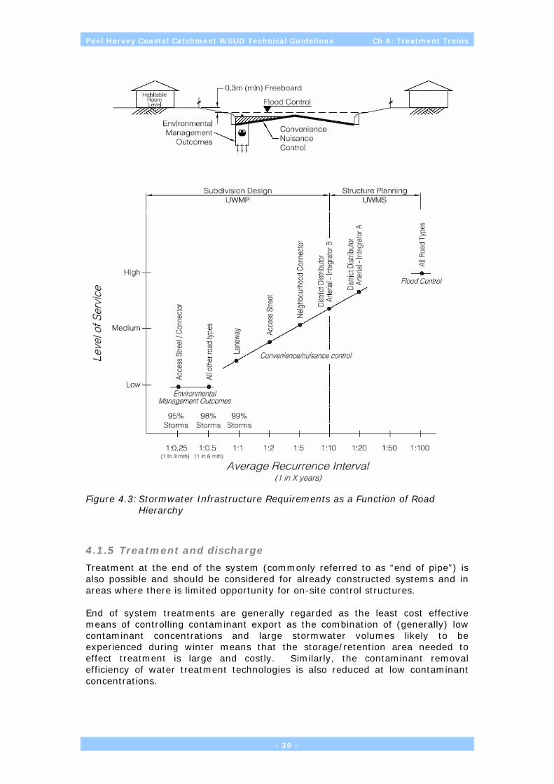
Peel Harvey Coastal Catchment WSUD Technical Guidelines Ch 4: Treatment Trains
Figure 4.3: Stormwater Infrastructure Requirements as a Function of Road Hierarchy
4.1.5 Treatment and discharge
Treatment at the end of the system (commonly referred to as “end of pipe”) is also possible and should be considered for already constructed systems and in areas where there is limited opportunity for on-site control structures. End of system treatments are generally regarded as the least cost effective means of controlling contaminant export as the combination of (generally) low contaminant concentrations and large stormwater volumes likely to be experienced during winter means that the storage/retention area needed to effect treatment is large and costly. Similarly, the contaminant removal efficiency of water treatment technologies is also reduced at low contaminant concentrations.
- 30 -
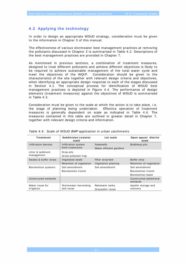
Peel Harvey Coastal Catchment WSUD Technical Guidelines Ch 4: Treatment Trains
- 31 -
4.2 Applying the technology
In order to design an appropriate WSUD strategy, consideration must be given to the information in Chapter 3 of this manual. The effectiveness of various stormwater best management practices at removing the pollutants discussed in Chapter 3 is summarised in Table 4.2. Descriptions of the best management practices are provided in Chapter 7. As mentioned in previous sections, a combination of treatment measures, designed to treat different pollutants and achieve different objectives is likely to be required to achieve sustainable management of the total water cycle and meet the objectives of the WQIP. Consideration should be given to the characteristics of the site together with relevant design criteria and objectives, when identifying an appropriate design response to each of the stages discussed in Section 4.1. The conceptual process for identification of WSUD best management practices is depicted in Figure 4.4. The performance of design elements (treatment measures) against the objectives of WSUD is summarised in Table 4.3. Consideration must be given to the scale at which the action is to take place, i.e. the stage of planning being undertaken. Effective operation of treatment measures is generally dependent on scale as indicated in Table 4.4. The measures contained in this table are outlined in greater detail in Chapter 7, together with relevant design criteria and information.
Table 4.4: Scale of WSUD BMP application in urban catchments
Treatment Subdivision (estate) scale
Lot scale Open space/ district scale
Infiltration devices Infiltration system Kerb treatments
Soakwells
Water efficient gardens
Bubbleup pits
Litter & sediment management
Drop pits
Gross pollutant trap
Swales & buffer strips Vegetated swale
Retention of vegetation
Filter strip/bed
Vegetation planting
Buffer strip
Retention of vegetation
Bioretention systems Soil amendment
Bioretention trench
Soil amendment
Soil amendment
Bioretention trench
Bioretention basin
Constructed wetlands Constructed ephemeral wetlands
Water reuse for irrigation
Stormwater harvesting and reuse
Rainwater tanks
Greywater reuse
Aquifer storage and recovery

Peel Harvey Coastal Catchment WSUD Technical Guidelines Ch 4: Treatment Trains
Table 4.2: Pollutant Reduction Efficiencies for Different Stormwater Quality Best Management Practices (based upon current knowledge)
Stormwater Quality Best Management Practice
Gross Pollutants
Coarse Sediment
Fine Sediment (suspended
solids)
Nutrients (P and N)1
Oxygen Demanding Substances
Oils and Greases2
Pathogens Metals3
Source Controls
Street sweeping H-M M - - L(S) - - L
Rubbish bins H-M - - - L(S) - - -
Public Awareness/Education4 L L L L L L L L
Local Infiltration - M-H M M M M M M-H
Porous pavements - H M-H M M M M M-H
Pollutant removal
Small scale devices
Litter baskets L-M - - - L - - -
Grates and entrance screens L - - - - - - -
Side entry pit traps L-M L - - L - - -
Baffle pits L L-M L - L - - L
Catch pits L L-M L - L - - L
Oil and grit separators L L-M L - L L-M L L
Nets H - - - - - - -
Medium scale devices
Litter and trash racks M L - - L - - -
Downwardly inclined screens H - - - - - - -
Floating litter booms L-M - - - - - - -
In-ground gross pollutant traps H-VH H L L L-M L - L
In-line separators M L-M - - - - - -
- 32 -

Peel Harvey Coastal Catchment WSUD Technical Guidelines Ch 4: Treatment Trains
- 33 -
Stormwater Quality Best Management Practice
Gross Pollutants
Coarse Sediment
Fine Sediment (suspended
solids)
Nutrients (P and N)1
Oxygen Demanding Substances
Oils and Greases2
Pathogens Metals3
Large scale devices
Open gross pollutant trap M-H H L L L L L L
Sediment trap L H L L L L L L
Hydraulically operated trash racks
H L-M - - - - - -
Conveyance Treatments
Filter strips M H M L-M L L(S) M(S) L
Grassed swales L-M M-H M L-M L L M(S) M
Sand filters - M-H M-H M M M M M
Estate level infiltration trench/basin
-
M-H M M M M M M-H
End of Train Treatments
Constructed ephemeral wetlands
M-VH H M M L M M(S) H
Source: Adapted from Blacktown City Council 2003
Legend: - negligible benefit L 10-30% pollutant reduction M 30-50% pollutant reduction H 50-75% pollutant reduction VH 75-100% pollutant reduction S Secondary benefit
1. May be dissolved or attached to fine sediment 2. Hydrocarbons (oils and greases) vary significantly in density and
solubility. Some will float, others will settle or attach to sediment, other will become soluble.
3. Usually adsorbed to fine sediment 4. Effectiveness will vary, requires ongoing maintenance
Notes: This table should only be used as a broad assessment tool. The above practices are mainly used during the operational phase, but some can be used during both construction and operation phase (e.g. wet basins and filter strips). Performance/efficiency ratings assume the practices are not being by-passed in a major storm event (i.e. they are appropriately sized) and that maintenance is sound. This is not an exhaustive list. It covers some of the commonly used practices. Linking each practice in a treatment train (e.g. combining a trash rack with a sediment trap) will improve the overall efficiency of the system. The % pollutant reduction efficiencies are conservative and will vary from site to site.

Peel Harvey Coastal Catchment WSUD Technical Guidelines Ch 4: Treatment Trains
Figure 4.4: Draft Conceptual WSUD best management practice decision tree
- 34 -

Peel Harvey Coastal Catchment WSUD Technical Guidelines Ch 4: Treatment Trains
Table 4.3: Performance of treatment elements against WSUD objectives
Issue to be addressed (Objective)
Measure
Aquifer
re
char
ge
Runoff v
eloci
ty
Runoff v
olu
me
Ero
sion C
ontr
ol
In-s
trea
m
bio
ta
Nutr
ients
Sed
imen
t lo
ad
Public
hea
lth
Wat
er
effici
ency
Comments
Landuse and Planning
Integration of natural drainage, recreation and vegetation retention in public open space
Recreation, flood and erosion control
Landscape Planning Reduce fertiliser and irrigation use
Vegetation planting and revegetation
Buffer re-establishment , biofiltration and erosion control
Water sensitive subdivision design
Design considerations may constrain some elements of the built-form
Source Controls
Street Sweeping Needs to be frequent prior to first rains
Porous pavements Carparks
Rainwater tanks Water for toilet flushing and irrigation
Greywater reuse For garden watering
Lot level Infiltration devices (eg. soakwells)
Most suited to permeable sands and some loams
Pollution removal
Soil amendment Phosphorus and particulate removal, suited to sandy soils
Bioretention basin Inexpensive to construct, reduces sediment loads
Gross pollutant traps Removes litter in commercial areas
Oil/grit separators Carparks
Groundwater use (SHARE systems)
Stormwater infiltration and irrigation using groundwater (borewater)
Conveyance treatments
Vegetated swales & buffer strips
Inexpensive to construct, reduces sediment loads
Bioretention strips Removes sediment, integrate with landscape master plan
Water sensitive road design
Reduces flow velocities, bottomless side entry pits to improve water quality and increase infiltration
Natural drainage systems
Reduces flow velocities
End of Train treatment
Detention storage areas Controls large storms
Constructed wetlands Preference for ephemeral designs,biofiltration of stormwater,
Source: Adapted from Coombes P., et al. 1999.
Note: See DoE Stormwater Management Manual Chapter 9 for further details of specific treatment practices.
- 35 -

Peel Harvey Coastal Catchment WSUD Technical Guidelines Ch 4: Treatment Trains
4.3 Applicability of treatments and land use
In general terms, the key aspects for selecting WSUD treatments are soil permeability and depth to groundwater. If the soils are well-drained (Soil Groups A and B, see Section 3.2.1) and the depth to maximum groundwater is generally greater than 1m below ground level then the initial consideration will be for the use of onsite infiltration. If the depth to groundwater is insufficient then onsite infiltration may still be practicable through the importation of fill or use of specifically developed infiltration devises (Section 7.1.1), however thes options are generally more costly. For ‘heavier’ soils (that is, increasing clay/loam content) the approach is quite different. In these instances the use of retention and/or detention techniques is likely to be the preferred approach. In some instances site contamination and/or geotechnical stability may require reconsideration of the above decision-tree. The following options for residential, commercial or rural- residenmtial development may be used to ensure WSUD outcomes are achieved, consitent with the requirements of the WSUD Local Planning Policy (PDC, 2006) and the Peel-Harvey Water Quality Improvement Plan (EPA, in prep).
4.3.1 Residential
Recommended technologies for residential areas at the lot scale include:
• Soil Amendment;
• In-situ infiltration;
• Rainwater reuse; and
• Strategic vegetation planting.
These elements are described in detail in Chapter 7. Lot-scale Landscaping and Building Design Guidelines and Construction Site Management Guidelines should be developed and may be implemented through a covenant placed on the title of all allotments by developers. The Design Guidelines should require:
• Installation of soakwells or other infiltration systems during construction of any buildings or ancillary building (soil permeability permitting);
• Runoff from driveways and paving surfaces to be diverted to lawn and gardens to prevent discharge of surface runoff beyond the allotment boundary;
• Use drought tolerant and low nutrient-demand landscaping within the front setback area; and
• Amendment of soil beneath lawn and landscaped areas to maximise the capture of phosphorus.
Where the above actions are achieved, the development could be marketed as a “sustainable housing” initiative by land developers. It is also beneficial if the cost of installing a packaged “waterwise” or “estuary-wise” landscaping design for the household garden is included in the house and land purchase price (geared for first home buyers).
- 36 -

Peel Harvey Coastal Catchment WSUD Technical Guidelines Ch 4: Treatment Trains
4.3.2 Commercial/General Industry
Commercial/General Industry landuse is generally the most demanding in terms of meeting WSUD design objectives. This is because the large areas of impervious surfaces (roofs, carparks and roads) associated with these types of developments create the potential to generate large volumes and peak flows of stormwater which must be catered for. It is common for light industrial/commercial/business areas to comprise 70% impervious surfaces. By comparison, approximately 30-40% of a residential area is generally regarded as impervious (see Section 4.1.4). The generation of runoff can; however, be limited by:
• using source control techniques;
• by not connecting the individual impervious areas together; and
• maximising retention/infiltration of rainfall by utilising the available porosity/hydraulic conductivity of the local soil profile.
Recommended technologies for commercial/general industrial areas include:
• In-situ infiltration;
• Detention systems and constructed ephemeral wetlands; and
• Water harvesting measures (including SHARE systems).
These elements are described in detail in Chapter 7. In order to achieve effective WSUD outcomes, it is recommended that Landscaping and Building Design Guidelines and Construction Site Management Guidelines are developed and implemented, possibly through a covenant placed on the title of all allotments. Covenant text and Design Guidelines should require:
• Prevention of contaminant and/or illicit discharges from commercial/industrial end uses to be considered during design phase. Prescribed premises (as defined under the Environmental Protection Act 1986) are not permitted uses under this zoning;
• Consideration should be given to contingency measures within the stormwater and groundwater management design in case of contaminant spill;
• A risk-based approach to provide greatest separation between potentially contaminant-generating end uses and stormwater and groundwater management systems (note: industrial precincts should be sewered);
• Runoff from aprons, roadways and paving surfaces to be diverted to landscaped areas or to soakwells to prevent discharge of surface runoff beyond the allotment boundary;
• Use of drought tolerant and low nutrient-demand landscaping within lots and streetscape;
• Exploration of opportunities for stormwater harvesting for non-potable or industrial/commercial reuse;
• Consideration of use of Superficial Aquifer to meet non-potable water demand and provide end of train treatment (soil permeability permitting).
- 37 -

Peel Harvey Coastal Catchment WSUD Technical Guidelines Ch 4: Treatment Trains
4.3.3 Special rural
Recommended technologies for low density residential/rural areas include:
• Advanced onsite wastewater treatment systems with subsoil irrigated reuse;
• Rainwater reuse (particularly where water services are unavailable);
• In-situ infiltration of stormwater; and
• Strategic revegetation planting.
These elements are described in detail in Chapter 7. In order to achieve effective WSUD outcomes, it is recommended that Landscaping and Building Design Guidelines and Construction Site Management Guidelines are developed and implemented, possibly through a covenant placed on the title of all allotments. Covenant text and Design Guidelines should require:
• Consideration of the size of lots in relation to soil suitability and stocking rates. This will have bearing the likelihood of dryland or irrigated grazing and on nutrient management. Covenants should reflect the carrying capacity of the land and preclude intensive animal activities (that is, which exceed carrying capacities as recommended by AgWA);
• Installation of soakwells during construction of any buildings or ancillary building (soil permeability permitting);
• Runoff from driveways and paving surfaces diverted to lawn and gardens to prevent discharge of surface runoff beyond the allotment boundary;
• Use drought tolerant, low nutrient-demand landscaping within the building envelope.
• Where retention of native vegetation is important, locally endemic landscape species should be prescribed and clearing be constrained to within building envelopes. Consideration of bushfire management requirements will be needed;
• The use of onsite wastewater systems that do not result in excessive nutrient loading and public health concerns. Onsite treatment and disposal systems should be located to ensure there is a minimum vertical separation distance between point of effluent disposal and highest groundwater and that these are not located closer than 100 metres to a wetland or watercourse; and
• Onsite treatment systems that employ advanced phosphorus removal technologies. The use of septic tanks is not supported.
Landowners should be required to verify currency of maintenance contracts for onsite wastewater systems to the Department of Health WA (a requirement of the Health Act).
- 38 -

Peel Harvey Coastal Catchment WSUD Technical Guidelines Ch 5: Performance Monitoring
5 PERFORMANCE MONITORING
Data to verify the effectiveness of water sensitive designs to reduce, eliminate or manage hard stand and urban pollutants leaving developments is rare in Western Australia. This is particularly true for information on how effective specific designs (and structural elements) have been for managing nutrients and other pollutants. The existing lack of data makes it essential to methodically collect and provide technical information so that the efficacy of specific designs and stormwater and groundwater management strategies can be verified or most importantly, improved so that future environmental and development requirements can be met. In order to address these information gap issues and to further improve WSUD approaches, proponents and practitioners should seek to further understand and apply methodical monitoring principles. A properly designed and consistently applied approach to monitoring WSUD systems should provide for comparisons both between stormwater and groundwater management systems and for individual design elements within different geomorphological settings. The paucity of existing data relating to the efficacy of specific stormwater and groundwater management designs per se should not be seen as a reason for rejecting innovative stormwater and groundwater management solutions. It is well worth reflecting on the current eutrophic status of the estuary and the current water quality of our wetlands and water courses to realise that the existing ‘business as usual’ drainage practices have not achieved satisfactory water quality outcomes to date. In accordance with the risk-based management approach espoused under the National Water Quality Management Strategy, it would seem more practical to encourage innovation as long as it is supported by a credible monitoring, reporting and adaptive management framework which permits modification and adjustment of such systems over time for optimal performance. Notwithstanding, this requirement does not overcome the need to also ‘flag’ practices known to be ineffective in certain soil/landuse settings and avoid these in the first instance.
5.1 Why Monitor?
Inappropriately managed urban run-off has contributed to the eutrophication of receiving water bodies around the world. Severe nutrient enrichment has affected the Peel-Harvey Estuary for over 30 years. Bio-stimulants such as filterable reactive phosphorus (FRP) and dissolved inorganic nitrogen (DIN, which includes ammonia, nitrite and nitrate) are major nutrient components. These constituents have great impact on water bodies because they are readily taken up by plants and microbes and can lead directly to excessive plant growth, hypoxia and consequent degradation of habitats and species biodiversity. In the Peel-Harvey region control of phosphorus is critical to many State policies and restoration initiatives. As well as nutrient contaminants in run-off other toxicants like metals, and persistent organic compounds like PCBs and DDT, pesticides (eg herbicides such as Atrazine or glyphosates) and their degradation products (epoxides), and in many situations, pharmaceuticals and personal care products can be in run-off and groundwater accession entering stormwater and groundwater management and water conveyance systems. These compounds can collectively act to degrade receiving water bodies. Consequently, it may be necessary to measure
- 39 -
Peel Harvey Coastal Catchment WSUD Technical Guidelines Ch 5: Performance Monitoring
for these contaminants to determine their concentration and source within the catchment, and if necessary see what treatment train processes can help reduce their availability to biota if nominal trigger values are exceeded. In WA, the paucity of comparative information on the effectiveness of WSUD practices means gathering baseline data is essential to compare conditions and establish efficacies of designs. In general, this information will allow us to validate the efficacy of existing Best Management Practices (BMPs), develop new ones and modify pre-existing ones over time. It should also be stressed that meaningful monitoring is reliant upon their being measurable and time-bound performance targets stated against which environmental performance is to be measured and reported. These targets need to be explicitly stated and set within the context of catchment and subcatchment-scale environmental objectives and are likely to be drawn from a number of sources (see Section 1.4.3). In terms of monitoring, a standardised monitoring approach will enable valid comparisons to be made both between practices and across different geomorphological settings. If non-standard practices (variable sampling frequently, laboratory analysis, QA/QC, etc) prevail it will be increasingly difficult to compare ‘apples with apples’ both within the same and across different practices.
5.2 Types of Monitoring
Monitoring programs can be classified according to what their primary purpose is and/or what they are planned to achieve. For example, a program to compare swales with traditional sediment stilling basins for reducing sediment loads in groundwater affected urban development would be an example of a “performance type” program. Conversely, programs often associated with new developments or retrofitting projects undergo three phases of monitoring – to establish baseline conditions, monitor performance to see if they comply with development conditions and lastly, to see whether they have achieved set targets or performance standards. They can thus be categorised as baseline, compliance or performance types.
5.2.1 Baseline/investigative
Baseline monitoring essentially describes conditions prior to development or during construction of development. It generates critical data that provides the basis for future comparison.
5.2.2 Compliance
Compliance monitoring is done post-development and must seriously grapple with quantity and quality issues as well as often describe impacts on set bio-indicators. It is undertaken to see if the development is meeting environmental planning conditions or set targets.
5.2.3 Performance
Performance monitoring can be considered to be more over-arching and includes the previous two types of monitoring. It is undertaken to see how effective WSUD designs have been in meeting pre-existing standards or more importantly,
- 40 -

Peel Harvey Coastal Catchment WSUD Technical Guidelines Ch 5: Performance Monitoring
in meeting WSUD criteria in a local WA setting. Thus if it is properly designed, it can be used to validate set designs used in stormwater and groundwater management modelling and validate best management practices for WA.
5.3 Principles of Monitoring
Measuring the presence, flow and contaminant characteristics of water is extremely difficult. Because water is so dynamic and complex, it is also imperative that the sources of variation or change in water data are adequately measured and accounted for. It is for this reason that practitioners of WSUD appreciate the various scales of measurement and error that influence good monitoring data. Sources of variation include, differences over time (temporal), differences between sites of locations along the treatment train or within the catchment (spatial), physical differences in volumes or discharge over time, sampling error (poor or inappropriate collection techniques) and laboratory error (inaccurate or too insensitive to measure the actual concentrations (that is, below the limits of detection). Failure to account for and standardise variation and error can make comparisons between datasets meaningless and the exercise of validating effectiveness of designs wasteful. It costs money and takes effort to monitor and thus it should be made relevant and meaningful to meet the objectives for monitoring. Consideration should be given to establishing a contributory scheme for monitoring the performance and efficiencies of stormwater and groundwater management systems associated with new developments. Provision for recouping the costs of designing and implementing a suitable monitoring plan could be incorporated into a Local Government endorsed Development Contribution Scheme. To ensure the data is independently collected, analysed and reported and meets the necessary QA/QC, a single contractor with demonstrated technical experience in these areas should be appointed by Local Government to provide these services for a 3-5 year period.
5.4 Developing a Monitoring Program
There are a numberof issues which should be considered when developing a monitoring program. These include:
• Defining the type of monitoring program required;
• Identification of extent of the study – spatial boundaries, scale and duration;
• Consideration of sampling design issues such as sampling sites, spatial variability of monitoring substances, frequency of sampling required, precision and accuracy required, measurement parameters; and
• Cost of the proposed program.
These issues are depicted in Figure 5.1.
- 41 -

Peel Harvey Coastal Catchment WSUD Technical Guidelines Ch 5: Performance Monitoring
Figure 5.1: Concepts to consider when designing a monitoring program (Source: ANZECC, 2000)
The National Water Quality Management Strategy (ANZECC, 2000) suggests the following steps are required to develop a monitoring program.
Step 1 Setting monitoring program
Step 2 Study Design
Step 3 Field sampling program
Step 4 Laboratory analysis
Step 5 Data analysis and implementation
Step 6 Repporting and information
Figure 5.2: ANZECC framework for development of a water quality monitoring program.
In order to reduce the potential for human error and inconsistent sampling, the monitoring program should be as simple as possible. This is not to say that limited consideration should be given to the program design. The water environment of the Peel-Harvey coastal catchment is an extremely complex and interconnected system, which requires site-specific knowledge of important
- 42 -

Peel Harvey Coastal Catchment WSUD Technical Guidelines Ch 5: Performance Monitoring
elements including surface water, groundwater, rainfall, climate changes and water balances. The chosen protocol should generate quality assured quantitative data that can be methodically compared over time or to other studies, which will meet the objectives of the monitoring program. It is also important to thoroughly document the monitoring program, particularly in terms of methods, including identification of any special considerations or settings for the program (eg. Acid sulphate soils, extreme nutrient enrichment and algal bloom issues).
5.4.1 Defining Monitoring Objectives
This is the most important step in the design of sampling or monitoring programs. It determines the size, intensity and quality of your monitoring program. It indicates what needs to be measured and why and how this will be done. In general, monitoring should be undertaken to validate or prove the effectiveness of treatment and control systems to satisfy development and environmental approval. Thus a generic objective may be to: “Measure the effectiveness of erosion and nutrient reduction treatment systems for Development A-Locality A1 for the next 5 years (2005 to 2010) in order to verify the appropriateness and effectiveness of structural controls and treatment trains selected and to inform future management and modification of these systems, as appropriate”. It should also be recognised there will be a need for baseline water quality data to be collected for natural and/or constructed stormwater and groundwater management systems before development occurs.
5.4.2 Other elements of a monitoring program
Other elements to be considered when developing a monitoring program include:
1. Location of sites A site registry is essential. Sites are best mapped and given GPS locations regardless of whether the program is to be fixed, ie at fixed sites or at random sites. If randomly located, they also need to be GPS referenced each time they are sampled.
2. Parameters to measure This includes what physical, chemical and biological items are to be measured. For example, stage height, flow-velocity, DO, Temperature, pH, Salinity-TDS-Conductivity, sediment composition, TN, TP, NH4+, NOx, FRP, TSS, DON, DIN, DOC, chlorophyll, phaeophytins, heavy metals (total and/or dissolved), herbicides (primary and/or their metabolites), TPH, BTEX, persistent organic compounds, pharmaceuticals, personal care products, phytoplankton (species-density), emergent and peripheral plants (distribution-biomass-leaf density), macrobenthos by defined size range, zooplankton, fish, amphibians and other vertebrates (all based on species presence-absence, abundance, biomass or size frequency).
3. Method of collection This includes describing extendable or water grab pole sampler ie grab sampler for water samples or corers-grabs-jars or settling plates for sediments, periphyton samplers, passive semi-permeable monitoring devices, etc. Method of collection includes how to collect the sample eg how deep to take the sample, how often the sample containers are rinsed before collection and whether they need to be special containers or prepared before collection. It also includes how many samples to take or replicates and how to label and identify each
- 43 -

Peel Harvey Coastal Catchment WSUD Technical Guidelines Ch 5: Performance Monitoring
sample. Reference to what steps to take to avoid contaminating samples is also wise, eg avoiding smokers fingers and contact with water samples.
4. Frequency of collection This defines when samples are taken. Many water samples are collected when certain water levels or discharge rates are reached and thus can be linked to autosamplers that automatically collect samples depending on stage height triggers created by command signals from in-situ loggers, many of which can be programmed or customised to various sampling frequencies. Often this specification will define weekly, monthly, 3 hourly etc times, seasonal, event or episodes.
5. Calibration of equipment The use of water quality probes, instruments and gauges require frequent calibration to ensure accurate measurements are made at all times. This is one source of variation or error that can be relatively easily controlled and is essential if data is to be used for comparison. Most water quality instruments require daily or weekly calibration and adjustments.
6. Safety considerations This is imperative as some waterways may be contaminated with toxic or potentially problematic elements where contact and inhalation would be unwise. It must include hazard identification, action taken to avoid the hazards (such as wearing Personal Protection Equipment-nitrile gloves, safety glasses and splash suits), and what to do in the event of an emergency eg contact names and phone numbers and a map to the nearest hospital.,
7. Laboratory analyses specifications Includes where to deliver samples for analysis ie laboratory business, defines limits of detection – limits of reporting and lab-reporting format for the data generated.
8. Quality control-assurance Refer to section below.
9. Data Analyses This outlines the general analyses that will be used. It explains how the data will be structured and analysed to make conclusions, validate best management practice designs or contribute to decision-making.
10. Reporting A schedule of when reports will be provided is necessary. This outlines the kind of reports eg data reports vs synthesis-interpretative reports that will be generated, how the reports will be structured-outlined and whom they will go to.
11. Data management Aside from ensuring data is gathered to objectives and of sufficient quality, a process of how data will be stored, where it will be kept and who (a nominated custodian) will be responsible for keeping results verified, validated and current. Furthermore, a statement for where the data will eventually be delivered is important, eg whether the dataset will be donated to the Department of Environment’s Water Information database (DoE). In this case, the database will need to conform the DoE’s requirements.
12. Communication Strategy This is almost a stand-alone process and defines how information will be disseminated to stakeholders.
5.5 Quality Assurance—Quality Control and Documentation Issues
A quality assurance-quality control (QA/QC) program for field sampling is intended to control sampling errors at levels acceptable to the data user. Thus it includes procedures designed to prevent, detect and correct problems in the sampling process and to characterise errors statistically, through quality control
- 44 -

Peel Harvey Coastal Catchment WSUD Technical Guidelines Ch 5: Performance Monitoring
samples. Major errors to avoid include faulty operation of sampling devices, changes in samples before measurement (eg contamination, chemical and/or biological changes) and incorrect sample labelling (Australian Guidelines for Water Quality Monitoring and Reporting, 2000). Quality assurance – is an integrated system of management activities involving planning, implementation, assessment, reporting and quality improvement to ensure that a process, item, or service is of the type and quality needed and expected by a client, eg establishing written protocols for data handling, sampling and instrument calibration Quality control – is the system of activities and checks that measure the attributes and performance of a process, item, or service against defined standards to verify that stated requirements are met and results are of an acceptable quality. This process is often referred to as auditing (US EPA, 2002). Establishing a rigorous QA/QC procedure is thus essential if results are to be compared to other monitoring programs measuring Best Management Practices or if they are to be used to validate the effectiveness and/or performance of specific WSUD elements.
- 45 -

Peel Harvey Coastal Catchment WSUD Technical Guidelines Ch 5: Performance Monitoring
(intentionally blank)
- 46 -

Peel Harvey Coastal Catchment WSUD Technical Guidelines Ch 6: References and Resources
6 REFERENCES AND RESOURCES
ANZECC/ARMCANZ. 2000. National Water Quality Management Strategy. No 7. Australian Guidelines for the Water Quality Monitoring and Reporting. October 2000.
AS/NZS 5667.1:1998. Water Quality – Sampling Part 1: Guidance on design of sampling programs, sampling techniques and preservation and handling of samples.
ASCE-USEPA. 2002. Urban Stormwater BMP Performance Monitoring: A Guidance Manual for Meeting the National Stormwater BMP Database Requirements. EPA-821-B-02-001. Prepared by GeoSyntec Consultants, Urban Drainage and Flood Control District, Urban Water Resources Research Council (UWRRC) of ASCE and Office of Water (4303T), US EPA, Washington, DC 20460.
AWA. 2005. Proceedings of the AWA Contaminants of Concern in Water Conference. Canberra, ACT. 2005.
Blacktown City Council. 2003. Stormwater Quality Control Policy Background Information and Guidelines for Application, Version 1, 17 August 2003.
Coombes P., Donovan I. and Cameron C. 1999. Water Sensitive Urban Development: Implementation issues for the Lower Hunter and Central Coast. Lake Macquarie City Council, Speers Point, on behalf of the Lower Hunter and Central Coast Environmental Management Strategy.
Coombes, P. 2001. Rainwater tanks for dual water supply and stormwater management, Lower Hunter and Central Coast Regional Environmental Management Strategy, online http://www.lhccrems.nsw.gov.au/ pdf_xls_zip/pdf_wsud/inwater_tanks_factsheet1.pdf
CRCCH. 2000. Draft Urban Stormwater Quality Monitoring Protocols. By Wong, THF, Breen, PF, Duncan, HP, Wooton, R, Walker, TA. For the Cooperative Research Centre for Catchment Hydrology – Working Document of Urban Stormwater Quality Program, Melbourne, Victoria.
Department of Environment and Swan River Trust, 2005, Decision Process for Stormwater Management in Western Australia, Department of Environment, Western Australia.
Department of Environment, 2004, Stormwater Management Manual for Western Australia, Department of Environment, Western Australia.
Department of Health, Department of Environment, Water Corporation 2005. Code of Practice for the Reuse of Greywater in Western Australia, January 2005.
Engineers Australia, 2006. Australian Runoff Quality: Guidelines to Water Sensitive Urban Design, Melbourne, Victoria.
- 47 -

Peel Harvey Coastal Catchment WSUD Technical Guidelines Ch 6: References and Resources
Gibb, S.W. 2000. Ammonia. In: Nollet, L.M.I. (Ed.) Handbook of Water Analysis. Marcel Dekker Inc., New York, USA.
Lake Macquarie Council. 2003. Stormwater Treatment Framework and Stormwater Quality Improvement Device Guidelines, September 2003.
NSW Landcom. 2004. Managing Urban Stormwater: Soils and Construction, Fourth edition, NSW Government, March 2004.
NSW Landcom. 2004. Water Sensitive Urban Design Strategy, Book Two: Best Planning and Management Practices, NSW Government, January 2004.
Parsons Brinckerhoff. 2005. Stormwater Management Manual Chapter 9 Structural Controls, Department of Environment, Government of Western Australia, January 2005.
Parsons Brinckerhoff. 2005. Forrestdale Sustainable Land Development Study Phase 4 – Urban Water Management Strategy, Department of Housing and Works, Government of Western Australia, September 2005.
Parsons Brinckerhoff, Ecological Engineering, Development Planning Strategies, Vector Management Consultants 2005. Draft Nambeelup Drainage, Nutrient and Wetland Management Plan — Stage 2 Working Paper, report to Department of Planning and Infrastructure, April 2005.
Parsons Brinckerhoff, Ecological Engineering, WMB 2004. Draft Water Sensitive Urban Design Engineering Procedures: Stormwater, Melbourne Water, with funding from Victorian Environment Protection Authority, June 2004.
Paskin, R. 2002. Water Sensitive Urban Design in the Sydney Region: Practice Note 7 —Landscape Measures, Lower Hunter and Central Coast Regional Environmental Management Strategy.
Peel Development Commission. 2006. Peel-Harvey WSUD Local Planning Policy — a model local planning policy to aid the achievement of integrated urban water management within the EPP Policy Area of the Peel-Harvey Coastal Catchment, Peel Development Commission, March 2006.
Taylor, A. 2004. Structural Stormwater Quality BMP Cost – Size Relathionship Information from the Literature, Cooperative Research Centre for Catchment Hydrology, January 2004.
Taylor, G.D., Fletcher, T.D., Wong, T.H.F., Breen, P.F. and Duncan, H.P. 2005. Nitrogen composition in urban runoff – implications for stormwater management. Water Research, 39: 1982-1989.
US Environmental Protection Agency. 2002. Guidance for developing Quality Systems for Environmental Programs EPA QA/G-1. (EPA/240/R-02/008). Washington, D.C.
Walsh, C.J., Leonard, A.W., Ladson, A.R. and Fletcher, T.D. 2004. Urban Stormwater and the Ecology of Streams. Cooperative Research
- 48 -

Peel Harvey Coastal Catchment WSUD Technical Guidelines Ch 6: References and Resources
Centre for Freshwater Ecology and Cooperative Research Centre for Catchment Hydrology, Canberra.
Water and Rivers Commission. 2002. Monitoring and evaluating river restoration works. Water Notes WN28, February 2002.
Water Corporation (undated) Waterwise Guide to Gardens, online [http://www.watercorporation.com.au/savingwater/savingwater_gardens.cfm], accessed 21 June 2005.
Water Corporation, 2003. Domestic Water Study, Perth 1998-2001.
Wong, T.H.F. 1999. Managing Urban Stormwater Using Constructed Wetlands Industry Report, Second Edition, Cooperative Research Centre for Catchment Hydrology, Clayton, Victoria, September 1999.
- 49 -

Peel Harvey Coastal Catchment WSUD Technical Guidelines Ch 6: References and Resources
(intentionally blank)
- 50 -

Part 2
Technical Information

(intentionally blank)

Peel Harvey Coastal Catchment WSUD Technical Guidelines Ch 7: Treatment Elements
7 INDIVIDUAL TREATMENT ELEMENTS
The following section provides a brief summary of various treatment elements that can be employed during the construct of Treatment Trains to achgieve best management practice. This section is not exhaustive and focuses on the elements most commonly employed in developments on the soils of the catchment. The design elements are not intended to be prescriptive and sizing, efficiency and detailed design and management will vary with specific applications. A more comprehensive range and more detailed advice on stormwater Structural Controls is contained in Chapter 9 of the Stormwater Management Manual for Western Australia (DoE, 2004). The elements are categorised according to sequencing and the Treatment Train hierarchy outlined in Section 4.
7.1 Subdivision scale (Estate)
The following best management practices are recommended for the Peel-Harvey region for consideration at the subdivision (estate scale). These treatments will need to be designed in to the plan at the structure plan stage, consistent with the requirememnts of the Peel-Harvey WSUD Local Planning Policy (PDC, 2006).
BMP type Specific example at subdivision scale
Infiltration devices Infiltration system
Kerb treatments
Litter & sediment management
Drop pits
Gross pollutant trap
Swales & buffer strips Vegetated swale
Retention and re-establishment of vegetation
Bioretention systems Soil amendment
Bioretention trench
Water reuse for irrigation Stormwater harvesting and reuse
7.1.1 Infiltration system
Manufactured, specialised systems, known as infiltration devices (Figure 7.1), can be installed to increase the effectiveness of stormwater infiltration at many scales. These products are highly permeable and are suited to various applications of subsurface filtration ranging from planter boxes and roof gardens, individual houses, grouped housing to roads and public open spaces. The drainage cell can also provide a structural blanket (or sheet) form of sub-surface drainage. Variations of these systems can be used to treat the stormwater as well so that the water can be reused or recharged to the groundwater.
- 53 -

Peel Harvey Coastal Catchment WSUD Technical Guidelines Ch 7: Treatment Elements
Figure 7.1: Infiltration tank system (Source: Atlantis Corporation, 2005)
7.1.2 Kerb treatments
There are various kerb treatments that can be used to increase infiltration of stormwater on site. These include:
• Flush kerbing
• Hit and miss kerbing
• Kerb openings
Figure 7.2 Flush kerbing, hit-and-miss kerbing and kerb openings (Source: City of Mandurah)
The various kerb treatments are commonly used in concert with grass swales and vegetative filters to enhance infiltration, sedimentation and litter removal. Kerbing treatments are most suited to sites with high soil permeability as a means of promoting onsite infiltration. Road surface slopes on local roads systems can also be employed to assist directing runoff to swales and grassed areas (see Figure 7.2). In some cases, particularly in areas subject to inundation or exhibiting low soil permeability, flush kerbing may not be advisable because of the need to utilise the roadway itself for flood storage under extreme conditions.
- 54 -

Peel Harvey Coastal Catchment WSUD Technical Guidelines Ch 7: Treatment Elements
7.1.3 Drop pits
Drop pits are commonly used to control litter and sediment. They consist of chambers fitted below the entrance to drains from road gutters (see Figure 7.3). When stormwater passes into the pit the more dense particulate material and sediment material settles to the base of the pit. This material is removed by evacuation/eduction. Drop pits are intended to be used at multiple locations throughout developments and can catch up to 80% of the litter in a catchment. Types of drop pits include:
• Oversized side entry pits in roadsides
• Oversized manholes in verges
Figure 7.3 Various drop pits (Source: Parsons Brinckerhoff, Essential Environmental Services)
Enlarged and ‘bottomless’ side entry pits are also employed to increase the storage capacity of the structure and to facilitate onsite infiltration. Side entry pits are often an integral component of the street-level stormwater and groundwater management system and are located at key intervals along street runs (usually about every 50-100m depending upon soil type and slope). The detailed design of a soakage side entry pit id provided in Figure 7.4. Taylor (2004) reported the typical capital cost of a side entry pit is approximately $1,700 to $2,900 per hectare of area treated.
- 55 -
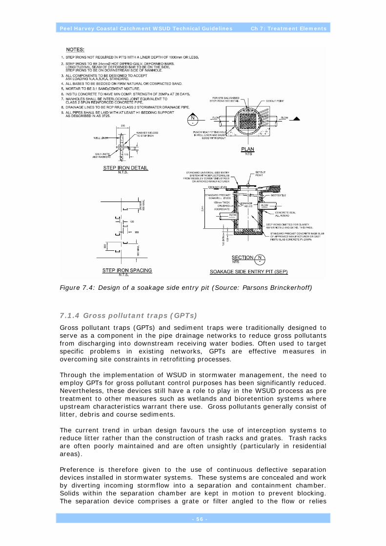
Peel Harvey Coastal Catchment WSUD Technical Guidelines Ch 7: Treatment Elements
Figure 7.4: Design of a soakage side entry pit (Source: Parsons Brinckerhoff)
7.1.4 Gross pollutant traps (GPTs)
Gross pollutant traps (GPTs) and sediment traps were traditionally designed to serve as a component in the pipe drainage networks to reduce gross pollutants from discharging into downstream receiving water bodies. Often used to target specific problems in existing networks, GPTs are effective measures in overcoming site constraints in retrofitting processes. Through the implementation of WSUD in stormwater management, the need to employ GPTs for gross pollutant control purposes has been significantly reduced. Nevertheless, these devices still have a role to play in the WSUD process as pre treatment to other measures such as wetlands and bioretention systems where upstream characteristics warrant there use. Gross pollutants generally consist of litter, debris and course sediments. The current trend in urban design favours the use of interception systems to reduce litter rather than the construction of trash racks and grates. Trash racks are often poorly maintained and are often unsightly (particularly in residential areas). Preference is therefore given to the use of continuous deflective separation devices installed in stormwater systems. These systems are concealed and work by diverting incoming stormflow into a separation and containment chamber. Solids within the separation chamber are kept in motion to prevent blocking. The separation device comprises a grate or filter angled to the flow or relies
- 56 -

Peel Harvey Coastal Catchment WSUD Technical Guidelines Ch 7: Treatment Elements
upon a vortex to concentrate solids towards the centre of the flow where they are allowed to settle to the bottom of the chamber. Removal efficiencies of 90% removal of solids >900micron have been reported for such devices (Wong, 1996). Swales and filter strips are also used within the Treatment Train to aid litter capture and prevent discharge of pollutants at the street-scale.
Figure 7.5: Schematic design of a Continuous Defective Separation dual outlet device (Source: Wong, 1996)
The costs of GPTs vary significantly based on size and application (i.e. total area from which the GPT is receiving stormwater). Taylor (2004) reported the following costs, which are based predominantly on cost surveys completed in NSW:
• Stream guard – catch basin insert: capital $290 and maintenance $200 per year.
• Ecosol RSF100: capital $430 to $903 and maintenance $200 per year.
• Ecosol RSF1000: capital $4,000 to $12,000 and maintenance $12 per hectare per month.
• CSR Humes Humeceptor: capital $10,000-$50,000 and maintenance $20 per hectare per month (suction cleaning).
• Rocla Downstream Defender: capital $12,000 to $36,000 and maintenance $20 per hectare per month (suction cleaning).
7.1.5 Vegetated swale
Vegetated swales are used to convey stormwater in lieu of use of pipes and provide the opportunity to maximise infiltration (Figure 7.6). Swales are used to infiltrate the smaller storm events (less than the 1year ARI events). They also provide for removal of coarse and medium sediment and are commonly combined with buffer strips. The system uses overland flow and mild slopes to slowly convey water downstream. Swales also provide a disconnection of impervious areas from hydraulically efficient pipe drainage systems resulting in slower travel times thus reducing the impact of increased catchment imperviousness on peak flow rates. The interaction between flow and vegetation along swales facilitates pollutant settlement and retention. Swale vegetation acts to spread and slow velocities, which in turn aids sediment deposition. Swales alone can rarely provide sufficient
- 57 -

Peel Harvey Coastal Catchment WSUD Technical Guidelines Ch 7: Treatment Elements
treatment to meet objectives for all pollutants, but provide an important function in stormwater management. They are particularly good at coarse sediment removal and can be incorporated in street designs to enhance the aesthetics of an area.
Figure 7.6: Examples of vegetated swales
Design considerations
To convey flood flows along swales, in excess of their design flow, pits draining to underground pipes can be used (Figure 7.7). Water surcharges from the swale down the pit. This is particularly useful in areas that have narrow verges, where a swale can only accommodate flows associated with the minor drainage system (eg. 5 year ARI) for a certain length. The longitudinal slope of a swale is the most important consideration in their design. They generally operate best with between 1% and 4% slopes. Slopes milder than this can tend to become waterlogged and have stagnant ponding due to difficulty in constructing swales with small tolerances. However, shallow underdrains or a thin sand layer can alleviate this problem by providing a drainage path for small depressions along a swale. For slopes steeper than 4%, riffles (small porous rock walls) along swales can help to distribute flows evenly across the swales as well as reduce velocities and scouring.
Figure 7.7: Landscape swale design to receive subsoil drainage
- 58 -
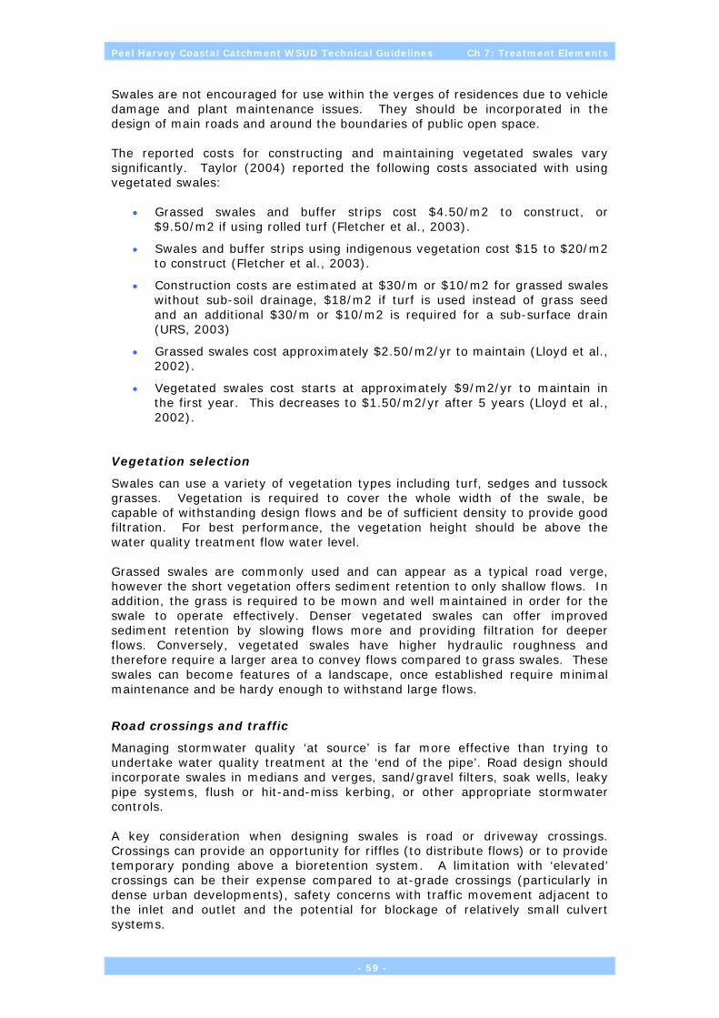
Peel Harvey Coastal Catchment WSUD Technical Guidelines Ch 7: Treatment Elements
Swales are not encouraged for use within the verges of residences due to vehicle damage and plant maintenance issues. They should be incorporated in the design of main roads and around the boundaries of public open space. The reported costs for constructing and maintaining vegetated swales vary significantly. Taylor (2004) reported the following costs associated with using vegetated swales:
• Grassed swales and buffer strips cost $4.50/m2 to construct, or $9.50/m2 if using rolled turf (Fletcher et al., 2003).
• Swales and buffer strips using indigenous vegetation cost $15 to $20/m2 to construct (Fletcher et al., 2003).
• Construction costs are estimated at $30/m or $10/m2 for grassed swales without sub-soil drainage, $18/m2 if turf is used instead of grass seed and an additional $30/m or $10/m2 is required for a sub-surface drain (URS, 2003)
• Grassed swales cost approximately $2.50/m2/yr to maintain (Lloyd et al., 2002).
• Vegetated swales cost starts at approximately $9/m2/yr to maintain in the first year. This decreases to $1.50/m2/yr after 5 years (Lloyd et al., 2002).
Vegetation selection
Swales can use a variety of vegetation types including turf, sedges and tussock grasses. Vegetation is required to cover the whole width of the swale, be capable of withstanding design flows and be of sufficient density to provide good filtration. For best performance, the vegetation height should be above the water quality treatment flow water level. Grassed swales are commonly used and can appear as a typical road verge, however the short vegetation offers sediment retention to only shallow flows. In addition, the grass is required to be mown and well maintained in order for the swale to operate effectively. Denser vegetated swales can offer improved sediment retention by slowing flows more and providing filtration for deeper flows. Conversely, vegetated swales have higher hydraulic roughness and therefore require a larger area to convey flows compared to grass swales. These swales can become features of a landscape, once established require minimal maintenance and be hardy enough to withstand large flows.
Road crossings and traffic
Managing stormwater quality ‘at source’ is far more effective than trying to undertake water quality treatment at the ‘end of the pipe’. Road design should incorporate swales in medians and verges, sand/gravel filters, soak wells, leaky pipe systems, flush or hit-and-miss kerbing, or other appropriate stormwater controls. A key consideration when designing swales is road or driveway crossings. Crossings can provide an opportunity for riffles (to distribute flows) or to provide temporary ponding above a bioretention system. A limitation with ‘elevated’ crossings can be their expense compared to at-grade crossings (particularly in dense urban developments), safety concerns with traffic movement adjacent to the inlet and outlet and the potential for blockage of relatively small culvert systems.
- 59 -
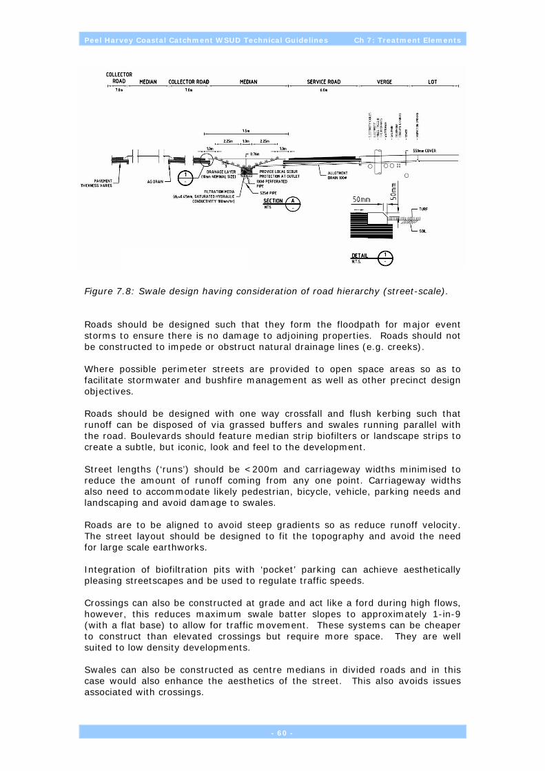
Peel Harvey Coastal Catchment WSUD Technical Guidelines Ch 7: Treatment Elements
Figure 7.8: Swale design having consideration of road hierarchy (street-scale).
Roads should be designed such that they form the floodpath for major event storms to ensure there is no damage to adjoining properties. Roads should not be constructed to impede or obstruct natural drainage lines (e.g. creeks). Where possible perimeter streets are provided to open space areas so as to facilitate stormwater and bushfire management as well as other precinct design objectives. Roads should be designed with one way crossfall and flush kerbing such that runoff can be disposed of via grassed buffers and swales running parallel with the road. Boulevards should feature median strip biofilters or landscape strips to create a subtle, but iconic, look and feel to the development. Street lengths (‘runs’) should be <200m and carriageway widths minimised to reduce the amount of runoff coming from any one point. Carriageway widths also need to accommodate likely pedestrian, bicycle, vehicle, parking needs and landscaping and avoid damage to swales. Roads are to be aligned to avoid steep gradients so as reduce runoff velocity. The street layout should be designed to fit the topography and avoid the need for large scale earthworks. Integration of biofiltration pits with ‘pocket’ parking can achieve aesthetically pleasing streetscapes and be used to regulate traffic speeds. Crossings can also be constructed at grade and act like a ford during high flows, however, this reduces maximum swale batter slopes to approximately 1-in-9 (with a flat base) to allow for traffic movement. These systems can be cheaper to construct than elevated crossings but require more space. They are well suited to low density developments. Swales can also be constructed as centre medians in divided roads and in this case would also enhance the aesthetics of the street. This also avoids issues associated with crossings.
- 60 -

Peel Harvey Coastal Catchment WSUD Technical Guidelines Ch 7: Treatment Elements
Another design issue is in regard to keeping traffic and deliveries off swales. Traffic (should swales be used for parking) can tend to ruin the vegetation and provide ruts that cause preferential flow paths that do not offer filtration. Traffic control can be achieved by selecting swale vegetation that discourages the movement of traffic or by providing physical barriers to traffic movement. For example, hit-and-miss kerbing (to allow distributed water entry, albeit with reduced uniformity of flows compared with flush kerbs) or bollards along flush kerbs can be used to prevent vehicle movement onto swales. With flood flows being conveyed along a swale surface, it is important to ensure velocities are kept low to avoid scouring and resuspension of collected pollutants and vegetation. These devices can be installed at various scales, for example, in local streets or on large highways. The design process for swales involves firstly designing the system for infiltration and conveyance and secondly ensuring the system has features that maximise treatment performance. Key design issues to be considered are:
1. Verifying treatment performance and relation to other measures in a treatment train
2. Determine design flows
3. Dimension the swale with site constraints
4. Above ground design:
• check velocities
• check slopes
• design of inlet zone and overflow pits
• check above design flow operation
5. Allowances to preclude traffic on swales
6. Recommend plant species and planting densities
7. Provision for maintenance
7.1.6 Vegetation retention and re-establishment
The preservation and re-establishment of corridors of deep-rooted vegetation provides for the lowering of natural water tables in a way that does not increase the volume of runoff lost from a development site. Retention of existing vegetation also reduces runoff and provides an opportunity for infiltration, acting as a stormwater sink (Figure 7.9). Where vegetation is to be retained within a development site, measures must be implemented at time of construction to protect the vegetation from construction impacts. This may include temportary fencing, erection of a sediment fence, marking of individual trees with tape and/or erection of signage (Figure 7.9). In contrast to traditional drainage systems, strategic vegetation planting (and revegetation) reduces recharge and groundwater levels through interception and evapotranspiration.
- 61 -

Peel Harvey Coastal Catchment WSUD Technical Guidelines Ch 7: Treatment Elements
Figure 7.9: Retention of vegetation with a development site and management of construction impacts (Source: Essential Environmental Services).
Revegetation seeks to establish a landscape that more closely resembles the pre-european development water cycle - before land clearing and establishment of drainage systems which now transport nutrient-rich floodwater to the estuary. Strategic revegetation is ideally suited to large parcels of land that have been highly cleared in the past. In particular, large lot rural residential developments are suited to revegetation where the lot sizes or soils may not be conducive to carrying stock and/or the land is subject to frequent waterlogging. The Mary Ellen Estate in Oakford is an example of the use of Strategic Vegetation as an adjunct to traditional drainage systems.
7.1.7 Soil amendment
Soil amendment is a means of controlling contaminants at source. It can be used to improve soil PRI for the purposes of enhancing onsite nutrient and metal retention and should be used in areas where infiltration of satormwater is to occur, such as areas of grass, gardens and swales. Blending or applying a layer of higher PRI soil 0-50 cm beneath the finished ground level of public reserves, school playing fields, and dry detention basins can provide an increased capacity for phosphorus retention within the soil profile, improve soil water storage and enhance the capacity of the soil to adsorb metals commonly found in road runoff. Soils with a PRI >15 are advocated; however, care should always be taken to ensure soil permeability is maintained. The amendment soil can affect the physical properties (as well as chemical properties) of the onsite soil which can result in lower hydraulic conductivity and hence lower rates of infiltration. Care needs to be taken to ensure that high PRI soil amendments do not contain excessive clay materials which may either adversely affect geotechnical considerations (and footing stability) or increase runoff coefficients. A variety of soil amendment materials can be utilised. Examples include:
• sands high in iron (eg Yellow Spearwood sands);
• calcareous or lime-rich sands (eg Karrakatta Soils); and
• brown loams (Foothill slope soils which may be blended with sands).
It should be noted that the use of industrial waste products for soil amendment should be treated with caution. The potential for contamination of industrial waste streams exists which could give rise to long term significant human health and ecological impacts.
- 62 -

Peel Harvey Coastal Catchment WSUD Technical Guidelines Ch 7: Treatment Elements
Figure 7.10: Residential subdivision amended with Spearwood (Yellow) Sand to provide both fill and improve soil PRI prior to installation of subsoil drainage system
The cost of providing fill for engineering purposes is generally $18/m3 (placed at a height of approximately 1.5m above the maximum groundwater level and 300–500mm above the 100 year flood event). The use of fill for improving soil PRI may increase cubic metre cost.
7.1.8 Bioretention trench
Bioretention trenches/basins are installed in surface water flow paths to remove pollutants by filtering stormwater runoff, facilitating infiltration and reducing stormwater discharge velocities. These structures can be installed at locations were stormwater discharges into rivers, channels or similar water recipients and are commonly located within the base of a swale. Bioretention trenches should receive stormwater as sheet flow. Concentrated flow will scour the surface and is likely to dislodge groundcover and plant roots (in the case of vegetated trenches), leading to failure. Minimising the length of unobstructed stormwater discharge upstream of the trench/basin will ensure it receives sheet flow. Factors such as width, gradient, soil permeability and density of vegetation influence the effectiveness of Bioretention trenches/basins. The site features (natural slope, soil properties, choice and placement of plants) will define the combination of these design factors and how the Bioretention trench/basin fits into the overall scheme for the site. Wider areas can hold greater volumes of water, as will those with higher embankments on the downslope side. Bioretention trenches/basins on land with slope less than 5% are better at trapping sediment. Soil that is friable and with an open pore structure allows greater infiltration of water compared to compacted heavy soils. Using vegetation to act as a baffle to slow down stormwater flow must be balanced against obstruction of flow that may cause backing up of waters and localised flooding. Plant species must be capable of withstanding periodic saturation of soil, foliage or trunk. The Bioretention trenches/basins should be monitored on a regular basis especially after major storm events. They may require periodic repair, mowing, replanting and sediment removal to remain effective. They are highly recommended for low to medium density urban areas as multi purpose landscape elements offering a form of garden bed.
- 63 -
Peel Harvey Coastal Catchment WSUD Technical Guidelines Ch 7: Treatment Elements
Figure 7.11: Design, sizing and locating detention basins (Source: Parsons Brinckerhoff)
Taylor (2004) reported the following approximate construction and maintenance costs for Bioretention trenches/basins:
• Turf buffer strips cost $3.50/m2 to construct.
• Sedge/mulch buffer strips cost $7.50/m2 to construct.
• Grass filter strip cost $10 to $15/m2 to construct.
• Native grasses and shrubs used in filter strips raise the construction cost to $20 to $50/m2.
7.1.9 Stormwater harvesting and re-use (SHARE) systems
Aquifer storage and recovery (ASR) is becoming increasingly popular in eastern Australia and refers to the storage of stormwater (or treated wastewater) in an aquifer by enhancing groundwater recharge (by injection or infiltration). The water is then later pumped back to the surface for irrigation use during dry periods. ASR can be a cost effective alternative to the construction and maintenance of large surface water impoundments or dams, but requires an understanding of the characteristics of the aquifer, the quality of the water used and the depth from which it is to be pumped. Detailed hydrogeological investigations are required to establish the feasibility of any ASR scheme. The near-surface aquifer underlying much of the Swan Coastal Plain is superficial (shallow) and laterally unconfined and sustains important groundwater-dependent vegetation as well as wetlands, caves and creeks. The use of the aquifer for sourcing drinking water, the permeable nature of the soils and the shallowness of the aquifer means that it is vulnerable to pollution. Accordingly,
- 64 -

Peel Harvey Coastal Catchment WSUD Technical Guidelines Ch 7: Treatment Elements
a risk-based approach to managing these groundwater systems generally precludes the use of raw or treated wastewater for ASR purposes. Domestic-scale ASR systems are used extensively on the Swan Coastal Plain and commonly take the form of lot-level soakwells and estate-level side entry pits and infiltration basins and swales (See Section 7.1.1). Injection is rarely, if ever, used with preference being given to passive infiltration. Abstraction is achieved during summer months through the use of shallow bores for irrigation of gardens and public open space. These systems do not employ aquifer injection or wastewater reuse and have been termed Stormwater Harvesting and Re-use (SHARE) systems. It is recommended that SHARE systems not be undertaken in locations where water tables are already less than 2 m or in areas where:
• saline groundwater ingress to sewers occurs
• water tables could rise to within 2 m of the soil surface as a result of enhanced recharge in areas of expansive clay soils
• other structures such as cellars or basements could be adversely impacted by rising water tables
• dryland salinity is an issue in the local catchment
Generally, runoff from paved areas will be of suitable quality for infiltration and recharge of the superficial aquifer if it has been subjected to best management practices outlined in this technical guideline. The interception and removal of sediment, leaves, pine needles and other gross pollutants prior to infiltration will also assist in maintaining suitable soil permeability within infiltration swales and basins. Roof runoff will generally be of acceptable quality for direct infiltration via soakwells in areas with sufficient soil permeability. A risk-based approach to groundwater management will be required in light industrial areas to ensure that process water is not allowed to infiltrate to the superficial aquifer. Lot-level infiltration of runoff from pervious surfaces must be isolated from industrial processes and discharges. In any event, light industrial areas should be serviced with a reticulated sewerage system to reduce the likelihood of illicit discharges to the groundwater. SHARE systems are designed to harvest increased flows attributed to urbanisation. Harvesting urban runoff and infiltrating this to recharge groundwater also requires that the quality of the infiltrated water be of sufficient quality not to degrade the existing and potential future environmental values (beneficial uses) of the groundwater resource. The level of treatment is dependant on the quality of the groundwater and its intended usage, but in most instances the range of management measures described in this manual will provide sufficient treatment prior to infiltration. It is recommended that at the SHARE planning stage, an inventory of existing and/or future environment values attributed to the groundwater system be compiled. This inventory may be included within a broader Urban Water Management Strategy (UWMS) and provide design objectives for planning the SHARE system and should identify the location of existing bores, their intended uses (eg monitoring, irrigation or drinking water supply) and groundwater-dependent ecosystems (phreatophytic vegetation, caves, wetlands and streams).
- 65 -

Peel Harvey Coastal Catchment WSUD Technical Guidelines Ch 7: Treatment Elements
The broad requirements of SHARE systems include:
• protecting or improving groundwater quality
• ensure that the quality of recovered water is fit for its intended end use
• protecting aquifers (and users) from being adversely impacted by drawdown, depletion or excessive abstraction
• Identify an Environmental Water Provision (EWP) sufficient to maintain and protect groundwater-dependent ecosystems under drying climatic conditions
• providing a suitable controlled and managed abstraction system such that there is reasonable assurance that the EWP can and will be met once the abstraction system is commissioned
• avoiding problems such as precipitation and clogging of the aquifer (eg iron precipitation and loss of permeability)
• ensuring impacts on surface water ecosystems ‘downstream’ of the stormwater harvesting point are acceptable and consistent with the design objectives (protecting environmental values and attainment of the Urban Water Management Strategy).
In addition to the physical requirements of a SHARE system, these systems may also require a groundwater allocation and licence for abstraction for the intended use. A thorough investigation of the required permits should be undertaken during the feasibility phase of planning a SHARE system.
Figure 7.12: Components of a well-configured SHARE system
Components of a SHARE system
A SHARE system that harvests stormwater typically contains the following structural elements (see Figure 7.13):
• soakwells, swales or infiltration basins are used to detain runoff and preferentially recharge the superficial aquifer with harvested stormwater;
• an abstraction bore to recover water from the superficial aquifer for reuse;
- 66 -

Peel Harvey Coastal Catchment WSUD Technical Guidelines Ch 7: Treatment Elements
• a reticulation system for irrigation reuse (will require physical separation from any potable water supply);
• potentially a water quality treatment system for recovered water (depending on its intended use). For example, this may involve removal of iron staining minerals;
• systems to monitor groundwater levels and abstraction volumes; and
• systems to monitor the quality of groundwater and recovered water.
The Health Department of Western Australia recommends against the use of untreated groundwater for human drinking water purposes in the residential area.
Evaporation Precipitation Evapotranspiration
Impervious Surfaces
Pervious Surfaces
Infiltration
Figure 7.13: Water balance considerations when planning a SHARE system. (Source: Parsons Brinckerhoff, 2005).
Upstream pollutant sources.
Each SHARE system must identify potential pollution sources within a catchment and plan risk management strategies, including pollution contingency plans. Comparisons with ambient groundwater quality and its environmental values and proposed end-use (for example, irrigation) will indicate the requirements for water quality treatment following abstraction. An evaluation of the pollutants that may be present within the recharge water needs to be carried out on a catchment basis. Pollutants will vary according to whether the catchment drains urban residential, urban industrial, rural or a combination of any of these catchment types. Some pollutants have the potential to precipitate or cause ‘clogging’ upon recharge and result in a significant reduction in permeability of the infiltration surface and/or receiving aquifer and should be considered at the planning phase.
Superficial Groundwater
Retention and Infiltration
Irrigation
Runoff
Pump
Recharge
- 67 -

Peel Harvey Coastal Catchment WSUD Technical Guidelines Ch 7: Treatment Elements
In particular, iron precipitation (and iron staining) is a common occurrence when using groundwater for irrigation.
Aquifer selection
The quality of water to be infiltrated should be no worse than the quality of water already in the aquifer. As discussed earlier, the aquifer may already be supporting environmental values (and beneficial uses) and the quality and flow requirements of these users will need to be considered when appraising the suitability of any particular site and aquifer. SHARE systems will not be supported within areas proclaimed under the Rights in Water and Irrigation Act as Underground Pollution Control Areas, or resources otherwise identified as existing and/or possible future drinking water supplies (Priority 1 and Priority 2 Groundwater Areas) or identified as Environmental Management Areas by the EPA. The existence of groundwater protection areas should be considered during the feasibility stage of SHARE planning. Factors to consider when choosing a suitable aquifer include:
• environmental values of the aquifer, including ecosystem maintenance of caves, wetland, phreatophytic vegetation, surface water systems and attendant human uses (such as irrigation and drinking water supply);
• adverse impacts on other aquifer users and the environment;
• an existing and/or future drinking water source area;
• sufficient permeability and storage within the aquifer;
• depth and hence costs of abstraction from the aquifer;
• existing over-allocation of the aquifer and groundwater resource;
• existing ambient groundwater quality and contaminant concentrations;
• risk of saline intrusion in the aquifer due to over-abstraction; and
• loss of aquifer permeability and/or infiltration due to precipitation of minerals or clogging.
Many of the stormwater treatment practices describe earlier are suitable as pre-treatment for SHARE systems. In general, methods that have long detention times are advantageous to reduce pathogenic microorganisms in addition to other pollutants. An advantage of using treatment with large storages (eg. wetlands) is the dilution effect should an isolated pollution event occur, thus reducing the risk of aquifer contamination.
Non-Potable Water Demand
Water Corporation has previously undertaken a study of domestic water use to collect data on different uses within a household, identify water use and trends, and to develop forecasting model and water use efficiency programs. The study determined the total water usage, ex-house usage, in-house usage and consumption patterns. It also reported the annual water usage, average daily consumption as well as peak day demand.
- 68 -

Peel Harvey Coastal Catchment WSUD Technical Guidelines Ch 7: Treatment Elements
Figure 7.14: Single Residential Household Water Usage. (Source: Water Corporation 2003)
Tables 7.1 and 7.2 summarise the annual and daily consumption for a single residential household. It can be seen that a substantial reduction (50-60%) in potable water use can be realised through the use of SHARE systems for household garden watering. The domestic water use study identified the peak day consumption pattern for in-house and ex-house uses (Figure 7.15). The peak day profile indicates peak consumption occurring between 5am and 9am in the morning and 5pm to 7pm in the evening. The consumption pattern is consistent with garden watering times currently imposed by sprinkler restrictions. It identifies the magnitude of household potable water which may be useful when sizing bores and pumps (or rainwater tank) requirements for in and/or ex-house uses.
Table 7.1: Estimated average annual water consumption for single residential household
In-house annual average use per household 190 kL
Ex-house annual average use per household 260 kL
Leaks 10 kL
Total annual average use per household 460 kL
Average annual use per person (household size: 2.63, ABS 2001)
175KL/person
Source: Water Corporation 2003
The State Water Strategy (Government of WA, 2003) proposes to achieve a target of 155 kL/person/yr.
- 69 -

Peel Harvey Coastal Catchment WSUD Technical Guidelines Ch 7: Treatment Elements
Table 7.2: Average Daily Water Consumption (For single residential household)
L/house/day % total use
In house use (excl toilet use) 411 33
Toilet flushing 112 9
Ex house 707 56
Leaks 29 2
Total 1259 100
Source: Water Corporation 2003
Figure 7.15: Average peak daily water usage (Source: Water Corporation 2003)
Water use for household garden watering is at a maximum during summer with an average total use of approximately 1600L/house/day (December, January, February). Ex-house water represents (Water Corporation 2003):
• 56 % of annual household demand (707L/house/day);
• 66% of average peak day household demand (1048L/house/day); and
• 84% of average peak hour household demand (140L/house/hr).
Costs and Maintenance
A recent analysis of a 400 lot SHARE system for a residential area at Brookdale (within the City of Armadale) has been used to provide costings (Table 7.3). Put simply, the unit cost of water derived from a SHARE system (for garden watering only) is currently comparable to the price of mains supplied water. However, with possible future water shortages and uncertainty regarding climate variability, it is likely that SHARE systems will become increasingly commercially viable. In addition, infrastructure savings in terms of averting additional regional
- 70 -

Peel Harvey Coastal Catchment WSUD Technical Guidelines Ch 7: Treatment Elements
drainage costs by harvesting and reusing stormwater have not been included in these costings.
Table 7.3: Unit Cost of Water from a SHARE system (400 lot system)
Operations and Maintenance Costs (Garden Use Only)
Item Annual cost ($)
Energy cost – bores and transfer pumps 5200
Operations and maintenance 50000
Administration costs (50%) 27600
Total 82800
Unit cost of Non-potable groundwater supply 67.4c/kL
Source: Parsons Brinckerhoff 2005
- 71 -

Peel Harvey Coastal Catchment WSUD Technical Guidelines Ch 7: Treatment Elements
7.2 Lot-scale Treatments
The following best management practices are recommended for consideration at the lot scale.
Treatment Lot scale
Infiltration devices Soakwells
Water efficient gardens
Swales & buffer strips Filter strip/bed
Vegetation planting
Bioretention systems Soil amendment
Water reuse for irrigation Rainwater tanks
Greywater reuse Figure 7.16 combines several treatment elements at the lot scale to achieve a more effective stormwater treatment system. These elements include a rainwater tank, vegetated filter strip, soil amendment and a soakwell.
Figure 7.16: Combining lot-scale treatment elements into a more effective treatment train (Source: Parsons Brinckerhoff).
- 72 -

Peel Harvey Coastal Catchment WSUD Technical Guidelines Ch 7: Treatment Elements
7.2.1 In-situ infiltration (Soakwells)
In-situ infiltration refers to the retention of stormwater and roof water within the property boundary, typically through the use of soakwells, although the careful contouring of gardens and lawns can provide for a degree of both water storage and garden irrigation. In areas where infiltration is constrained by high winter groundwater or shallow rock, innovative landscaping should be employed which provides on-site retention and infiltration of storm events. Alternatively, runoff can be centrally collected for reuse.
Design Guidance:
• Landscaping and Building Design Guidelines should require soakwells to be installed during the building construction process, as part of the roof and guttering works.
• Allotments should aim to infiltrate all the stormwater and roof water generated on-site. The minimum requirement shall be to at least retain the 1 year Average Recurrence Interval rainfall event on low permeability sites.
This design element is probably the most commonly applied on the coastal plain and is used to reduce the entrainment of contaminants and to reduce peak flows ‘at source’. The element is particularly suited to sites which have sandy, permeable soils where infiltration is rapid and efficient. At the lot-scale the approach is commonly employed in the form of soakwells and infiltration swales. Infiltration through coarse media (such as a permeable sand) is an effective means of filtering course contaminants, particulates and gross pollutants and is regarding as an essential design elements for sandy soil sites.
7.2.2 Water efficient gardens
Approximately 60% of household water is used for watering lawns and gardens. This is a low level use of a high quality (drinking quality) resource and opportunities to utilise water harvesting or reuse schemes to meet this demand should be considered.
Figure 7.17: Examples of water saving garden design using native plantings (Source: Essential Environmental Servicves)
- 73 -

Peel Harvey Coastal Catchment WSUD Technical Guidelines Ch 7: Treatment Elements
Notwithstanding the source of the water, designing a garden to be water efficient involves consideration of the layout, use of materials and the efficient delivery of irrigation water. Though lawn areas are the major users of garden water, considerable savings can be made in the other areas of the garden. Garden and landscaping design should seek to:
• Minimise the extent of water consuming planting;
• Maximise the use of water conserving elements and techniques; and
• Apply the basic principle of hydrozoning to planting design (grouping plants on the basis of having similar water requirements).
Planning
The following site characteristics should be investigated when planning a garden:
• orientation, sun and shade, the prevailing winds;
• topography, water run off;
• soil types, water holding capacity compaction, water repellence, fertility levels;
• availability of accessible ground water;
• views both inwards and outwards; and
• overall area available for the garden.
The garden design should also accommodate the following:
• utility spaces (clothes drying, compost and storage areas);
• outdoor living spaces (barbecues, seating areas);
• special needs (vegetable garden, swimming pool);
• functional and aesthetic requirements;
• plant preference and design styles (native/exotic, formal/informal);
• maintenance expectations; and
• budget.
WSUD garden design principles
Using the following garden design principles will contribute to a less water demanding garden:
• Do not plant areas unless it is necessary for functional or aesthetic reasons;
• Maximise the use of non-planting treatments such as permeable or porous paving and mulches;
• Beware of excessive unshaded paving which can be hot and glaring. Vary materials and arrange planting to frame and shade paved areas;
• Use windbreaks, pergolas, screen, lattice, shadecloth and vines to shelter the house, outdoor living areas and plants;
- 74 -

Peel Harvey Coastal Catchment WSUD Technical Guidelines Ch 7: Treatment Elements
• Keep planted areas dense and consolidated. Sparse scattered plants are more difficult to water efficiently than ones that are in defined areas; and
• Keep lawn to the minimum consistent with functional and aesthetic requirements. Avoid planting lawn on slopes or in narrow necks or paths which are difficult to water efficiently and maintain.
Figure 7.18: An example of a Water Garden designed to utilise roof runoff
Hydrozoning
Apply the principles of hydrozoning to plant selection and arrangement:
• A broad selection of plants may be used, but keep high water-demand plants to a minimum; and
• Arrange plants having similar water requirements together (hydrozoning) and take this into account when deciding soil improvement and mulching, and when managing irrigation.
Some leading nurseries label their plants with drop icons signifying the appropriate hydrozone, described in three categories:
• Primary (3 drops) high water use plants;
• Secondary (2 drops); moderate water use plants; and
• Elemental (1 drop); low water use plants.
- 75 -

Peel Harvey Coastal Catchment WSUD Technical Guidelines Ch 7: Treatment Elements
Soil improvement in the garden (Soil Amendment)
Adding organic matter to the soil improves both its moisture and nutrient holding capacity thus saving on water and fertiliser. It is particularly important to improve the top 15-20 cm of soil where the feeder roots of plants will develop. Old animal manures, compost and proprietary products are ideal soil improvers. Mix them in equal parts with the soil prior to planting out. Use these points as a guide:
• Shrubs, groundcovers and climbers 30 cm in depth and up to 50 cm across;
• Trees 40 cm deep and 1 m across and bedding plants 25 cm deep for the whole bed;
• Garden soils are just as prone to becoming non-wettable as are lawn areas; and
• A regular application of a soil wetting agent in spring is recommended.
Do not force plants on with large amounts of strong fertilisers. These produce lush growth that has a high water transpiration rate and is more prone to insect and fungal attack. Slow release fertilisers, including animal manures, are the best type. They produce steady, healthy growth and minimal leaching of nutrients into the ground water.
Mulching
Mulching is beneficial for all plants. Mulch should be spread over an entire planted area to a minimum thickness of 50 mm. Organic mulches enriched with animal manures are beneficial when applied thickly (to 30 cm) around the drip zone of fruit trees. They should be topped up as necessary during spring, summer and autumn to maintain a minimum thickness (after settling) of 15 cm. Organic mulches are preferred because they:
• break down over time and feed the plants;
• improve the soil organic matter content as they break down;
• reduce evaporation loss from the surface;
• encourage earthworms and soil microbial activity;
• restrict weed growth. any weeds which do germinate are easy to remove;
• prevent wind and water erosion;
• protect the roots from daily temperature fluctuations; and
• improve the appearance of the garden area.
Raw materials like woodchips, chipped tree waste or similar are ideal mulching materials. However, if the mulch is watered regularly you may need to add nitrogen in the form of animal manures, blood and bone to prevent the natural breaking down process from drawing nitrogen away from the plants. Lawn clippings do not make good mulch, they are best composted. However, if mixed with a coarser material like chipped prunings or woodchips they can be used as mulch. Old newspapers can be used under mulch as a weed control layer, however, thick overlapping layers of newspapers may prevent water penetration.
- 76 -
Peel Harvey Coastal Catchment WSUD Technical Guidelines Ch 7: Treatment Elements
For general garden use mulches should be spread at 50-75 mm thick. Always leave a breathing space of 50 mm around stems and trunks of plants. In garden areas, mulches should be topped up as necessary; perhaps twice a year in both autumn and spring. Mulches should never be raked up, turned over, dug in or disturbed in any way. To do so will damage the fine feeder roots which plants develop in the zone between the mulch and the soil.
7.2.3 Rainwater tanks
Previous studies have shown that the storage and reuse of rainwater in the catchment is largely constrained by the size of the storage system required to meet summer demand. The lack of significant rainfall during the summer months in the Peel region, when demand is at its highest, negates much of the potential savings normally afforded by rainwater tanks. It may be possible to overcome some of the above limitations through the use of Aquifer Storage and Recovery systems (see Section 7.1.9), whereby the ‘tank’ is effectively the groundwater system which is accessed via domestic bores. These systems are not, however, suitable for drinking water supply and should be used for garden watering and possibly toilet-flushing only (water quality permitting). In rural areas which are not serviced with a reticulated water supply, rainwater tanks remain the only viable option for drinking water supply. The Health Department of WA advises against the use of untreated groundwater for drinking water supply because of the risk of contamination. Although the installation of rainwater tanks may not represent the most cost effective means of storing rainwater for reuse within individual allotments they have several beneficial effects on the urban water cycle, including reduced demand for potable water, reduced total runoff and peak flow volumes. Rainwater tanks will only achieve the above outcomes if the tank is connected to the building’s internal plumbing system.
Design Guidance:
• Aquifer Storage and Recovery Systems afford a high degree of water cycle management as it provides for water harvesting, storage and reuse and which will reduce the use of drinking water for irrigation purposes. ASR is, however, commonly restricted to areas with permeable (sandy) soils and where the finished fill level provides for more than 2 metres depth to groundwater;
• ASR systems are best suited to meet garden and landscape irrigation needs and should not be used as a source of drinking water supply in urban areas;
• In residential and business-commercial estates, the installation of rainwater tanks and their internal plumbing to the toilet, laundry and bathroom tap outlets should be a consideration for developers and outlined as an opportunity for water efficiency in the Landscaping and Building Design Guidelines;
• However, the collection of rainwater for human consumption (drinking and cooking) in estates affected by heavy traffic (>25,000vpd) or industrial emissions is not recommended. Accordingly, the Design Guidelines for commercial-industrial estates should restrict the use of harvested rainwater for toilet, irrigation and other non-potable uses.
- 77 -

Peel Harvey Coastal Catchment WSUD Technical Guidelines Ch 7: Treatment Elements
Residential allotments abutting roads where the traffic volume exceeds 25,000 vehicles per day may also be restricted;
• Rainwater tanks should be fitted with float valves to enable automatic top-up from the reticulated potable water supply, where available. The tank and plumbing installation must comply with AS/NZS 3500.1.2: Water Supply – Acceptable Solutions, which requires rainwater tanks with dual water supply must maintain an air gap between the float valve and tank full water level; and
• Mesh screens must be fitted over all box gutters which harvest rainwater and the tank itself, and a first flush device must also be fitted immediately prior to the rainwater tank inlet.
Water consumption
All urban mains water is treated to drinking water standards, despite the fact that less than 4% of domestic water is for drinking. Rainwater collected from roofs and stored in tanks is an alternative water source for domestic uses such as garden watering and toilet flushing.
Water quality
Research by the University of Newcastle has shown that rainwater used in hot water systems is compliant with the Australian Drinking Water Guidelines, provided the temperature setting is maintained at greater than 50°C (Coombes, 2001). Water quality from rainwater tanks has also been shown to be statistically compliant with the Australian Drinking Water Guidelines. However, it is recommended that rainwater in urban areas be passed through an approved filtration system before drinking. Acceptable water quality can be maintained in rainwater tanks provided that:
• Mesh screens are installed over all inlets and outlets to prevent leaves, debris and mosquitoes from entering the tank;
• A first-flush device is installed to discard the first portion of rainfall (see Figure 7.19); and
• Gutters are regularly cleared of leaves and debris.
Rainwater Tank
Rainwater leaks through a small hole
Rainwater from roof
Mesh screen
Overflow to tank
Rainwater Tank
Rainwater leaks through a small hole
Rainwater from roof
Mesh screen
Overflow to tank
Rainwater Tank
Rainwater leaks through a small hole
Rainwater from roof
Mesh screen
Overflow to tank
Figure 7.19: Diagram of a first-flush device (Source: Adapted from Coombes, 2001).
- 78 -

Peel Harvey Coastal Catchment WSUD Technical Guidelines Ch 7: Treatment Elements
Rainwater should not be collected from roofs coated with lead- or bitumen-based paints, or from asbestos-cement roofs. Roofs constructed from galvanised iron, ColorbondTM, or ZincalumeTM, slate or ceramic tiles provide acceptable water quality. Special roof guttering is not required for rainwater collection. Normal guttering is sufficient provided that it is kept clear of leaves and debris.
Approvals required may include:
• Department of Health
• Water Corporation
• Local government
Australian standards and tank design
The Standard AS/NZS 3500.1.2: Water Supply — Acceptable Solutions provides guidance for the design of rainwater tanks with dual water supply (rainwater and mains water). Rainwater tanks with dual water supply must maintain an air gap, and be designed and connected in accordance with Figure 7.20.
Overflow
Mains water top up
Maximum water level
Rainwater TankPump
Air gap(AS/NZS 3500.1.2 and AS 2845.2)
Height of water above invert of overflow (AS/NZS 3500.1.2)
Water supply to house
Overflow
Mains water top up
Maximum water level
Rainwater TankPump
Air gap(AS/NZS 3500.1.2 and AS 2845.2)
Height of water above invert of overflow (AS/NZS 3500.1.2)
Water supply to house
Overflow
Mains water top up
Maximum water level
Rainwater TankPump
Air gap(AS/NZS 3500.1.2 and AS 2845.2)
Height of water above invert of overflow (AS/NZS 3500.1.2)
Water supply to house
Figure 7.20: Design details to prevent backflow for a rainwater tank with mains water top up. (Source: Coombes, 2001).
To maximise water savings and stormwater management benefits, tank capacity should hold 5–10 kL. The required capacity will depend on water use, rainfall and roof area. Design of the rainwater tank should make provision for:
• A minimum availability volume (to ensure that water supply is always available), approximately 250–750 L;
• A rainwater storage volume; and
• An air space for additional stormwater management.
If the volume of the stored water falls below the minimum availability volume, the shortfall can be overcome by topping up the tank with mains water to the required level. A simple float valve system can be installed to do this automatically.
- 79 -

Peel Harvey Coastal Catchment WSUD Technical Guidelines Ch 7: Treatment Elements
The rainwater storage volume is the total volume available in the tank to store rainwater below the overflow pipe. The air space between the overflow pipe and the top of the tank can be used to provide ‘stormwater detention’, thereby delaying the delivery of excess roof water to the stormwater management system. The rainwater storage volume and the overlying air space both provide stormwater management benefits. The configuration of plumping required for rainwater tanks is shown in Figure 7.21. Water supply from the rainwater tank is directed to the household via a small pump. When tank water levels are low, such as during hot, dry periods, the tank is topped up with mains water. In the event of pump or power failure, the rainwater tank can be by-passed.
Mains top up volume
Rainwater space
Air space used for detention Overflow
Trickle top up from mains supply
Pump
Water supply to house
Cross-sect ion Plan
Pump
Mains supply for other uses (drinking)
Rainwater tank
Float Water supply for irrigation, toilet flushing etc
Bypass in event of power failure
Stop valve
Trickle top up from mains as required
Figure 7.21: Design details for rainwater tank with mains water top up (Source: Coombes, 2001).
Costs and maintenance
The costs and benefits of installing a rainwater tank is shown in Table 7.4.
Table 7.4: Costs and savings associated with installing a rainwater tank
Tank Capacity Cost/Savings
5 kL 10 kL
Purchase and installation of rainwater tank on concrete slab with a pump to supply irrigation, toilet flushing and hot water systems
$1,600 $2,000
Reduction in mains water use 45% 54%
Annual saving $107 $132
Savings from using rainwater for irrigation, toilet flushing and hot water over 50 year period
$0.15 per kL $0.28 per kL
Source: Adapted from Coombes, 2001. Rainwater tanks should be checked every two years for sludge at the bottom. Removal of accumulated sludge may be required once every 10 years. Frequency of cleaning will depend on the amount of sediment entering the tank. Installation of a first-flush device will exclude sediment, leaves and debris from entry to the tank.
- 80 -

Peel Harvey Coastal Catchment WSUD Technical Guidelines Ch 7: Treatment Elements
Sediment, leaves and debris should be regularly removed from the first flush device. Roof gutters should be cleaned every 3–6 months to remove leaves and debris.
7.2.4 Greywater reuse
Greywater is potentially useable for irrigation of garden areas, lawns and public open space. Greywater reuse systems are most commonly employed in special residential areas where lot size is sufficient to achieve an appropriate irrigation loading and setback from neighbouring properties. Greywater is water that has not come into contact with toilet waste (black water) and comes from the bath, shower, bathroom washbasins, clothes washing machine and laundry trough. Wastewater from the kitchen sink and dishwasher should not be reused as these streams may contain heavy loads of organic materials, fats and caustic additives.
Instances where greywater is not permitted
Approval is not granted for the installation of greywater systems under the following circumstances:
• The greywater system (or system design) is not approved by the Executive Director, Public Health (this often being related to unacceptable human health exposure/risk issues associated with reuse);
• The property is connected to a municipal effluent reuse system and the Sewerage Service Provider will not approve the diversion of greywater from the reuse scheme;
• The property is in an environmentally sensitive area (as defined in Part 1 of the Code of Practice for the Reuse of Greywater in Western Australia). For example, within .an Underground Water Pollution Control Area (UWPCA) or within the vicinity of a Conservation Category Wetland;
• Inappropriate site conditions exist (e.g. unsuitable sandy soils and/or elevated groundwater levels); and
• Insufficient property area is available to achieve the necessary setbacks and area required for irrigation.
Approved greywater systems
The following Greywater systems are approved by the Department of Health for use in Western Australia:
• An ‘Executive Directory, Public Health approved system’ (approved on an individual basis);
• Systems which utilise a sedimentation tank and sub soil trench irrigation system constructed as prescribed in Part 3 of Code of Practice for the Reuse of Greywater in Western Australia (Department of Health 2005);
• Systems which convert disused septic tank systems to Greywater systems as detailed in Appendix 3 of Code of Practice for the Reuse of Greywater in Western Australia (Department of Health 2005); and
• Systems which convert Aerobic Treatment Units (ATU) to greywater systems as detailed in Appendix 4 of Code of Practice for the Reuse of Greywater in Western Australia (Department of Health 2005).
- 81 -

Peel Harvey Coastal Catchment WSUD Technical Guidelines Ch 7: Treatment Elements
A current list of Greywater systems approved by the Department of Health for use in Western Australia can be obtained from for local government authority or the Wastewater Management Branch of the Department of Health on (08) 9388 4999.
Greywater irrigation options
The appropriate Greywater irrigation method is dependent on the treatment level, as listed in Table 7.5.
Table 7.5: Greywater Irrigation Options According to Treatment
Treatment Greywater Reuse Application
Untreated Greywater Bucketing
Primary treated greywater (i.e. treatment by either a sedimentation tank and/or a diversion device)
Sub-soil trench or sub-surface drip irrigation*
Secondary treated to a 20 mg/L BOD, 30 mg/L suspended solid and possible disinfection to achieve < 10 cfu thermotolerant coliforms/100 mL
Surface spray irrigation, sub-strata drip irrigation, sub-surface drip irrigation, or sub-soil trench.
Source: Department of Health 2005 * Dependent on type of filter system
Issues to consider
Some of the issues to address when considering the installation of a greywater system include:
• Once a greywater system is installed, it becomes the householder’s responsibility to ensure it is operated and maintained according to the manufacturer’s instructions;
• Some greywater systems may require weekly cleaning or replacement of filters, periodic desludging of treatment tanks, the manual diversion of greywater back to the sewer in winter, flushing of the irrigation lines, occasional replacement of pumps, and the periodic testing of the soil pH;
• Greywater must be contained entirely on the property and must not run onto neighbouring properties or be allowed to pool, which can create a nuisance;
• Greywater must not come into contact with edible plants or vegetables, and can only irrigate fruit plants where the fruit does not come into direct contact with it;
• Greywater must not come into contact with a drinking water supply or the stormwater drainage system;
• Using products with high phosphorous, sodium, or boron levels, or bleaches and softeners can affect your garden and the environment, and should be used sparingly when the water is directed into a greywater reuse system;
• The system must be designed to prevent mosquito breeding; and
• The system must be designed to avoid pooling, blockage, leakage and overflow.
- 82 -

Peel Harvey Coastal Catchment WSUD Technical Guidelines Ch 7: Treatment Elements
Approval to install a greywater system
All greywater system applications for single dwellings up to 10 people are to be made to and approved by the local government authority, which should be contacted to determine the information to include with an application. For systems that are able to accommodate more than ten people, the application will need to be referred to the Department of Health. Local authorities will only issue approval for the use of the greywater system in a sewered location when the Water Corporation has indicated no objections to the application. All plumbing works are to be conducted by a licensed plumber, who must also obtain approval from the Water Corporation for any required connection or modification to the plumbing works connected to the sewer system.
Designing a Greywater system
There are four steps involved in designing a greywater reuse system. These are:
• calculating greywater volumes;
• sizing greywater tanks;
• sizing irrigation areas; and
• reducing size allowances.
Calculating greywater volumes
Greywater flow is based on the number of bedrooms rather than the actual number of occupants in a dwelling, because the number of bedrooms will remain constant over time. Daily domestic greywater volumes are listed in Table 7.6.
Table 7.6: Daily domestic greywater generation rates
Domestic Greywater Volumes (Litres per Day)
Greywater Source Number
of Bedrooms Kitchen* Laundry Bathroom
Total Greywater Flow
2 or less 72 126 153 351
3 96 168 204 468
4 120 210 255 585
5 or more 144 252 306 702
Source: Department of Health 2005. Notes: Figures based on an allocation of 117 L greywater flow per person per day, comprised of 24
L for kitchen, 42 L for laundry and 51 L for bathroom. * A 1,800L sedimentation tank is required for Greywater systems that include kitchen
greywater systems that include kitchen greywater unless otherwise approved by the Executive Director, Public Health.
Sizing greywater tanks
Greywater systems than treat all greywater streams (i.e. kitchen, bathroom and laundry) must have a sedimentation tank that has a minimum volume of 1,800 L, unless otherwise approved by the Executive Director, Public Health. Greywater systems that only treat bathroom and/or laundry greywater via sedimentation tank must be designed to provide at least 24 hour combined
- 83 -

Peel Harvey Coastal Catchment WSUD Technical Guidelines Ch 7: Treatment Elements
retention for the daily flow of greywater (i.e. double the daily flow) or higher if a spa bath is connected.
Sizing irrigation areas
Greywater irrigation systems are sized on whether they use sub-soil trench irrigation or drip/spray methods. Systems are sized on the capability of the soil to receive the greywater (i.e. the loading infiltration rate (LIR)) and the estimated daily greywater flow. The permeability of the soil is to be determined in accordance with the requirements of the Health (Treatment of Sewage and Disposal of Effluent and Liquid Waste) Regulations 1974. Subsoil Trench Irrigation Sizing
The size of the greywater irrigation trench is calculated using the following equation:
L = V / (LIR x A)
L = length of trench in metres V = daily greywater volume in litres per day (L/day) LIR = Loading Infiltration Rate (L/m2/day). The infiltration rates for
greywater flow are determined on the soil type. A = surface area of the trench in m2 (i.e. the sides below the invert of the
distribution pipe and base of the trench per linear metre) The LIR can be higher, if the system has a diverter and alternating trenches (i.e. two trenches that have a diverter box that can change the flow of greywater, allowing one of the trenches to be turned off at any time). By diverting the flow of greywater or shutting off the irrigation area, the irrigation area can rest and dry out. This rejuvenates the soil’s ability to receive greywater. If the system has not diverter and does not have alternative trenches, a lower infiltration rate must be used. Drip or Spray Irrigation Sizing
The required irrigation area size should be calculated on the basis of 10 L/m2/day in sand and gravel/loam or for other soils in accordance with AS 1547:2000 — Onsite Domestic Wastewater Management. Where appropriate, engage an Irrigation Association of Australia Certified Irrigation Designer to ensure the system is designed correctly.
Table 7.7: Standard Greywater Loading Infiltration Rates
Loading Infiltration Rate (L/m2/day) Time for Water to Fall 25 mm** (minutes)
Soil Texture
System with diverter and/or alternating
trenches
Systems with no diverter and non-
alternating trenches
1 to 5 Sand 30 15
5 to 60 Loams or gravels
20 10
>60 Impervious clays
As approved by the Executive Director, Public Health.
Source: Department of Health 2005.
- 84 -

Peel Harvey Coastal Catchment WSUD Technical Guidelines Ch 7: Treatment Elements
** a procedure which measures soil permeability by recording the time taken for water in a 300 mm x 300 mm hole to fall 25 mm. See Schedule 8 of the Health (Treatment of Sewage and Disposal of Effluent and Liquid Waste) Regulations 1974 for a full explanation of the method.
Reduced sizing allowance for subsoil trenches
The method for calculating length reduction allowance for subsoil trenches is provided in the Code of Practice for the Reuse of Greywater in Western Australia (Department of Health 2005). The trench lengths for 200 mm x 200 mm trench using the standard LIR or double LIR are listed in Table 7.8. Generally, subsoil trench lengths may be halved only if a greywater system has a:
• Overflow device, allowing greywater to automatically overflow into the primary sewerage system should a blockage occur, and
• Manual diverter, allowing the home owner to divert the greywater to the primary sewerage system in rainfall periods.
The homeowner must also:
• Divert greywater back to the primary sewerage system (i.e. sewer, septic tank or ATU) during high rainfall seasons to allow the soil to rest and rejuvenate and
• Plant out the irrigation trench to uptake the greywater.
A reduced system does not apply to a one or two bedroom house. One and two bedroom homes should be sized using the standard LIR.
Table 7.8: Trench lengths for a 200 mm x 200 mm trench using the standard LIR or a higher (double) LIR
Trench Lengths
Sand Gravel/Loam No. of Bedrooms
LIR
(Loading
Infiltration
Rate)
Bathroom
only
Laundry
only
Bathroom
& Laundry
Bathroom
only
Laundry
only
Bathroom
& Laundry
Higher 6 m 5 m 10.5 m 8.5 m 7 m 15.5 m Up to 3 bedrooms
(4 persons)
Standard* 11 m 9 m 21 m 17 m 14 m 31 m
Higher 7 m 6 m 13 m 11 m 9 m 19.5 m 4 bedrooms
(5 persons)
Standard* 14 m 12 m 26 m 21 m 17.5 m 39 m
Higher 8.5 m 4 m 15.5 m 13 m 10.5 m 23 m 5 bedrooms
(6 persons)
Standard* 17 m 14 m 31 m 25.5 m 21 m 46.5 m
Source: Department of Health 2005 * See Table 5.9 for loading infiltration rates. Figure calculated using systems
- 85 -
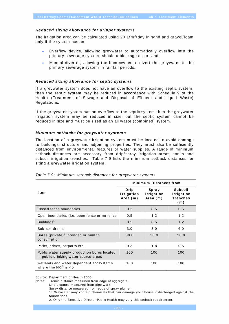
Peel Harvey Coastal Catchment WSUD Technical Guidelines Ch 7: Treatment Elements
Reduced sizing allowance for dripper systems
The irrigation area can be calculated using 20 L/m2/day in sand and gravel/loam only if the system has an:
• Overflow device, allowing greywater to automatically overflow into the primary sewerage system, should a blockage occur, and
• Manual diverter, allowing the homeowner to divert the greywater to the primary sewerage system in rainfall periods.
Reduced sizing allowance for septic systems
If a greywater system does not have an overflow to the existing septic system, then the septic system may be reduced in accordance with Schedule 9 of the Health (Treatment of Sewage and Disposal of Effluent and Liquid Waste) Regulations. If the greywater system has an overflow to the septic system then the greywater irrigation system may be reduced in size, but the septic system cannot be reduced in size and must be sized as an all waste (combined) system.
Minimum setbacks for greywater systems
The location of a greywater irrigation system must be located to avoid damage to buildings, structure and adjoining properties. They must also be sufficiently distanced from environmental features or water supplies. A range of minimum setback distances are necessary from drip/spray irrigation areas, tanks and subsoil irrigation trenches. Table 7.9 lists the minimum setback distances for siting a greywater irrigation system.
Table 7.9: Minimum setback distances for greywater systems
Minimum Distances from
Item Drip
Irrigation Area (m)
Spray Irrigation Area (m)
Subsoil Irrigation Trenches
(m)
Closed fence boundaries 0.3 0.5 0.5
Open boundaries (i.e. open fence or no fence) 0.5 1.2 1.2
Buildings1 0.5 0.5 1.2
Sub-soil drains 3.0 3.0 6.0
Bores (private)2 intended or human consumption
30.0 30.0 30.0
Paths, drives, carports etc. 0.3 1.8 0.5
Public water supply production bores located in public drinking water source areas
100 100 100
wetlands and water dependent ecosystems where the PRI3 is <5
100 100 100
Source: Department of Health 2005. Notes: Trench distance measured from edge of aggregate. Drip distance measured from pipe work. Spray distance measured from edge of spray plume. 1: Greywater may contain chemicals that can damage your house if discharged against the
foundations. 2. Only the Executive Director Public Health may vary this setback requirement.
- 86 -

Peel Harvey Coastal Catchment WSUD Technical Guidelines Ch 7: Treatment Elements
3. For description of Public Drinking Water Supply Areas (PDWSA) or wetland positioning contact DoE. Greywater systems within 100 m of a Priority 1 Drinking Water Source Protection Area must be approved by DoE.
All greywater systems (i.e. the dripper line or base of trench) must achieve a minimum of 500 mm clearance above the highest seasonal groundwater level. The “Perth Groundwater Atlas” is available on the Waters and Rivers Commission website at www.wrc.wa.gov.au. The atlas enables an estimate to be made of the depth to groundwater beneath a property.
Below ground greywater tanks must be a minimum of 1.2 m from any boundary or building or structure.
- 87 -

Peel Harvey Coastal Catchment WSUD Technical Guidelines Ch 7: Treatment Elements
7.3 Urban Park Land Treatments
The following design elements are often used at the end of the Treatment Train or are incorporated into public open space:
Treatment Open space/ district scale
Infiltration devices Bubbleup pits
Litter & sediment management
GPTs
Swales & buffer strips Buffer strip
Bioretention systems Soil amendment
Bioretention trench
Bioretention basin
Constructed wetlands Constructed ephemeral wetlands
Water reuse for irrigation Aquifer storage and recovery
7.3.1 Bubble up pits
Bubble-up pits (see Figure 7.22 and Figure 7.23) must ensure that stormwater runoff stored in the structure can be dissipated. This is achieved by making the base of the structure permeable (subject to the nature of the underlying soil permeability). The structures are commonly used to direct and dissipate stormwater through infiltration swales and basins, thereby reducing peak flow rates within a catchment and/or estate.
Figure 7.22: Example of bubble-up structure for discharging allotment runoff into a swale. Note the sediment fence protecting the vegetation from impacts of construction (Source: Essential Environmental Services)
Bubble up pits are also able to ber covered by boardwalks or other structures to enhance amenity.
- 88 -

Peel Harvey Coastal Catchment WSUD Technical Guidelines Ch 7: Treatment Elements
Figure 7.23: Typical design of a bubble up pit
7.3.2 Buffer strips, bioretention trench/basin
Land that is subject to inundation or in immediate proximity to waterways, wetlands or drainage lines are considered to have a high risk of nutrient export. These lands usually contribute significantly to the overall ecological function of the waterway/wetland system and are generally not suitable for urban development unless vegetated swales, buffer strips, bioretention trenches/basins and strict building and landscaping design covenants are employed. The treatment efficiency of buffer strips is variable for different pollutants and on their own may not provide sufficient treatment to meet the water quality objectives, but buffer strips still provide the overall ecological functionality required for healthy waterways and wetlands. When used as part of the overall WSUD, buffers are a valid and useful tool for managing pollutants at-source and during infiltration and conveyance for water quality outcomes.
7.3.3 Revegetation
In some cases re-establishment or restoration of degraded buffers using locally endemic plants may be warranted and beneficial. This will require integration with a Landscape Master Plan at the time of Structure Planning to minimise irrigation and fertiliser usage.
- 89 -

Peel Harvey Coastal Catchment WSUD Technical Guidelines Ch 7: Treatment Elements
7.3.4 Compound Systems
A number of ‘compound’ designs have recently been developed which has seen multiple WSUD design elements incorporated within the one structural feature. For example, a recent innovative design has seen the integration of a bubble-up pit and linear wetland with soil amendment to promote infiltration, biofiltration and nutrient removal (Figure 7.24). Such innovation is to be encouraged as it is likely that, given the elements are sized and located appropriately, the systems will afford a greater degree of contaminant removal efficiency than a simple structure. It is recommended that where innovative designs are promoted that suitable monitoring programs be undertaken to appraise their effectiveness.
Figure 7.24: Example of a compound system incorporating swale, soil amendment, vegetated biofiltration and bubble-up pit elements within the one design.
7.3.5 Constructed ephemeral wetlands
Constructed wetlands can be an effective end-of-pipe system for treating urban and rural stormwater runoff where other upstream BMPs in the treatment train have been exhausted. However wetlands built on the Swan Coastal Plain have generally had limited success at removing nutrients to date, largely because designs have lacked an appreciation of contaminant transport mechanisms (particulate or soluble), groundwater interaction and mosquito control strategies.
Figure 7.25: Ephemeral wetlands are usually depicted by dense vegetation.
- 90 -
Peel Harvey Coastal Catchment WSUD Technical Guidelines Ch 7: Treatment Elements
Generally, the creation of permanent open water bodies (lakes) will not supported by the Department of Environment when this involves the artificial exposure of groundwater (eg through excavation); the use of lined lakes that require groundwater pumping to maintain water levels in summer; or the modification of a conservation category wetland (CCW) or lake designated under the Environmental Protection (Swan Coastal Plain Lakes) Policy 1992 (see Section 1.4.1). Wetland construction should only be considered when environmental and health concerns (eg hydrology, water quality, mosquitoes, midges, algal blooms, acid sulfate soils and iron monosulfide minerals) can be adequately addressed through design and realistic maintenance regimes. Seasonal (ephemeral) wetland types are the preferred design option for constructed wetlands. Constructed ephemeral wetlands are characteristically shallow (less than 2 m deep) wetlands that have fluctuating water levels and are seasonally dry. While such wetlands may be designed to contain pockets of deeper permanent water, their characteristic feature is the presence of emergent macrophytes, (aquatic plants whose parts protrude above the waterline). Epiphytes (algae growing on the surface of aquatic plants) and biofilms are often associated with macrophytes in wetlands and can be important for nutrient removal. Emergent vegetation also provides for a diversity of habitat and provides refuge for fauna in an urban setting (particularly from predation by domestic pets). Constructed wetlands may contain dampland, sumpland and/or lake sub-elements and comprise graded hydrozones (water permanency) for effective nutrient removal. Cyclical wetting and drying within ephemeral wetlands is particularly important for denitrification (nitrogen removal). The inlet zone of a constructed wetland may, for instance, resemble a sumpland, but the dominant feature of the system should be the macrophyte (dampland) zone, containing emergent vegetation that requires or can withstand wetting and drying cycles.
Design considerations
The key design considerations of a constructed ephemeral wetland are:
• Flood storage outcomes are best achieved through at source infiltration and the use of restored wetlands, floodplains and riparian zones (i.e. as opposed to large end of train constructed wetlands for flood storage);
• Endeavour to replicate the natural wetting and drying cycles of wetlands located on the Swan Coastal Plain;
• Site selection is crucial and should involve consideration of seasonal groundwater level fluctuations, soil type, hardpan, permeability and incidence of acid sulphate soils;
• Sizing of constructed wetlands should be based upon water treatment objectives, more so than flood storage capacity;
• The wetland should be designed to ensure the bathymetry (ie water level regime) does not favour and allow invasive non-target emergent species to dominate (for example, Typha orientalis);
• Ensure a diversity of locally indigenous wetland species are planted at the time of construction to enable species to find their ‘niche’ in terms of optimal depth and hydroperiod;
- 91 -

Peel Harvey Coastal Catchment WSUD Technical Guidelines Ch 7: Treatment Elements
• Opportunity for integration of flood storage with water quality treatment, habitat and visual and passive recreational amenity;
• Opportunity to incorporate wetland features into multiple use corridors and to promote walkability at the estate-level;
• Limit irrigation, pesticide and fertiliser usage in proximity to the wetland through appropriate landscape design;
• Performance in terms of water quality treatment is a result of the form of the contaminant (particulate or soluble), contaminant loading and hydraulic (water) loading (and hence residence time) of the wetland;
• Hydraulic effectiveness of a wetland reflects the interaction of three factors — detention period, inflow characteristics and storage volume — and defines the overall percentage of catchment runoff introduced to the wetland for treatment. As a general rule of thumb, to be effective for water quality treatment a constructed wetland should comprise approximately 1-2% of the total catchment area, otherwise excessive hydraulic loading and short-circuiting is likely to reduce the hydraulic retention time and limit the effectiveness of biofiltration;
• Wetland design and water quality treatment to focus on removal of suspended solids, nitrogen and phosphorus and
• The proposed wetland maintenance and monitoring regime should be detailed in a Wetland Management Plan.
Site specific characteristics such as topography, groundwater, geotechnical properties, surface water hydrology, water quality, vegetation and acid sulphate soils will need to be investigated as part of the design and location decision making process. Initial design considerations should focus on whether the wetland should be an on-line or off-line system. An on-line wetland system incorporates the stormwater treatment within the drainage channel, whereas an off-line wetland system involves the diversion of low-to medium runoff away from the stormwater and groundwater management system for treatment. The choice of arrangement is usually governed by site characteristics, land availability, storage and handling of extreme events. The level of control and ease of maintenance has seen a growing preference for off-line wetland systems. Taylor (2004) reported the following cost estimates for constructed wetlands based on limited costing data (predominantly from east coast of Australia):
• In Penrith/Blacktown, design and construction cost $500,000 per hectare of wetland surface area and $10,000 per hectare for maintenance in the first 2 years, which decreases to $5,000 per hectare;
• In Brisbane, typical construction costs in approximately $3,400 to $17,900 per hectare of area treated or $730,000 per hectare of wetland area. Typical maintenance costs approximately $8,200 per year; and
• In Melbourne, typical greenfield wetland construction costs $12,000 per hectare of area treated.
More recently, CSBP Pty Ltd has constructed a large nitrogen stripping wetland at its Kwinana plant. Construction, planting and instrumentation costs for the wetland were $650,000 for a 6,0000 m2 wetland (excluding the cost of the HDPE liner).
- 92 -
Peel Harvey Coastal Catchment WSUD Technical Guidelines Ch 7: Treatment Elements
Key wetland features
The recommended features of a constructed wetland filter are:
• to consist of a minimum of two cells — an open water inlet zone and a macrophyte (vegetation) zone, with an associated high-flow by-pass system for the macrophyte zone;
• the macrophyte (vegetation) zone should be allowed to fill and drain and dry out regularly in response to the intermittent inflow of stormwater runoff from the catchment;
• the wetland outlet design should consist of a riser, with the lowest outlet hole located to create a ephemeral pool equal to 10–15% of the total storage volume;
• the wetland should have a length-to-width ratio exceeding 3:1, unless steps are taken to incorporate such features as flow spreader berms and islands to promote more uniform flow pattern;
• wetland vegetation and basin depth variation should be banded perpendicular to the flow path; and
• the outlet structure should provide for manual control of water level and duration of inundation to facilitate vegetation establishment and management.
The creation of constructed wetlands requires the coordination of civil works and wetland vegetation establishment. While the management of civil works is well understood, site management of the wetland establishment phase is not. Wetland vegetation establishment requires well-prepared planting stock, good site preparation and an understanding of the likely water level regime. The provision of well-prepared planting stock includes:
• selection of locally indigenous species;
• selection of species suited to the water level regime, making sure to diversify the plantings to maximise successful establishment and colonisation; and
• propagation of plant stock, which may require many months.
Good site preparation includes:
• provision of suitable top soil; and
• control of weeds and pests.
The interaction of hydrologic, hydraulic and botanical factors directly determines the treatment performance of constructed wetlands for stormwater management.
Vegetation specification
Locally indigenous wetland plant species should be selected based on the water regime, microclimate and soil types of the region. It is best to consider a diverse array of local species within the planting regime, rather than to focus solely on one or two plant species. In this way the ultimate hydrological regime of the wetland will control species dominance and success.
- 93 -

Peel Harvey Coastal Catchment WSUD Technical Guidelines Ch 7: Treatment Elements
Other factors of influence such as previous land use history, physiological and structural characteristics, and natural distribution should also be considered. Where possible remnant vegetation areas should be retained and/or rehabilitated in keeping with the wetland objectives. Mosquito management is often a major issue for constructed wetlands within urban areas and may require careful consideration at the planning stage (see Section 4.1). Table 7.10 lists plant species suitable for constructed wetlands within the Peel-Harvey coastal plain catchment.
Table 7.10: Common wetland species
Species Common name
Baumea articulata Jointed Twig Rush
Baumea juncea Bare Twig Rush
Baumea preissii Broad Twig Rush
Baumea rubiginosa River Twig Rush
Baumea vaginalis Sheath Twig Rush
Bolboschoenus caldwellii Marsh Club Rush
Carex appressa Tall Sedge
Carex fascicularis Tassel Sedge
Carex tereticaulis Tube Sedge
Centella asiatica Gota Kola
Cotula coronopifolia Water Buttons
Cyperus gymnocaulis Spiny Flat Sedge
Eleocharis acuta Common Spike Rush
Eleocharis sphacelata Tall Spike Rush
Gahnia trifida Coast Saw Sedge
Hemarthria uncinata Mat Rush
Hopkinsia anoectocolea Steel Rush
Isolepis nodosa Knotted Club Rush
Juncus kraussii Shore Rush
Juncus pallidus Pale Rush
Juncus pauciflorus Elegant Rush
Juncus subsecundus Finger Rush
Lepidosperma effusum Spreading Sword Sedge
Lepidosperma longitudinale Pithy Sword Sedge
Lepdiosperma gladiatum Coast Sword Sedge
Leptocarpus diffusus Tall Mop Rush
Lepyrodia hermaphrodita
Marsilea drummondii Nardoo
Dielsia stenostachya
Schoenoplectus validus Lake Club Rush
Schoenus subfascicularis Bog Rush
- 94 -
Peel Harvey Coastal Catchment WSUD Technical Guidelines Ch 7: Treatment Elements
Species Common name
Sporobolus virginicus Water Couch
Tremulina tremulus
Triglochin procera Water Ribbons
Villarsia albiflora
7.3.6 Mosquito control
The stormwater management system should be carefully designed to minimise the risk of mosquito breeding. Areas requiring design consideration are:
• detention areas;
• multiple use corridors;
• surface water flow paths; and
• roadside gullies.
Ideally all components of a stormwater treatment train should be designed to ensure that they do not contribute to or create an environment which increases the opportunity for mosquito breeding onsite. There are three stages involved in developing a mosquito management program:
• Stage 1 — Establish a mosquito monitoring program to highlight the existing levels of mosquito activity, species diversity and density, prior to any ground disturbing work being undertaken;
• Stage 2 — Design the stormwater management system to ensure that waterway and wetland areas, multiple use corridors, road gullies (etc) do not contribute to onsite mosquito breeding; and
• Stage 3 — Ongoing maintenance and management of the stormwater system to ensure that it continues to operate as designed, thereby reducing the risk of conditions likely to promote onsite mosquito breeding.
Mosquito Monitoring Program
A mosquito monitoring program should be established at least twelve months prior to any ground disturbing activities being undertaken. This is recommended by the Environmental Protection Authority in Guidance Statement No. 40 for Management of Mosquitoes by Land Developers (June 2000). The monitoring program would allow base data to be collected regarding species density, species diversity and highlight seasonal fluctuations. This data is important as it helps to establish the pre-existing impact that mosquitoes breeding offsite have on the development. Ongoing monitoring during the development stage will also identify any changes in mosquito activity which may be as a result of any construction work. A pre-construction survey should be carried out to establish if there are existing onsite breeding areas and an adult mosquito monitoring program established prior to commencement of any ground disturbing activities.
- 95 -

Peel Harvey Coastal Catchment WSUD Technical Guidelines Ch 7: Treatment Elements
Stormwater and groundwater management strategies
The stormwater and groundwater management strategies should be carefully designed to minimise the risk of mosquito breeding. Areas requiring consideration are:
• Constructed wetlands— (as bio-detention basins) should be designed with locally indigenous, emergent wetland vegetation to maximise nutrient uptake and biomass cycling. Ephemeral wetland designed is preferred, allowing for seasonal drying to reduce nutrient enrichment and opportunities for mosquito breeding. The use of locally indigenous, frog friendly fish species (e.g. Western Minnow, Western Pygmy Perch, Swan River Goby) to mitigate nuisance midge and mosquito problems should be considered;
• Multiple use corridors — It is essential that management of water after each storm event through infiltration and transfer to a storage basin is completed within five days. These corridors are generally landscaped, therefore it is important that they are maintained to ensure that no pooling remains after each storm event;
• Living streams — The aim for mosquito control is to ensure a good rate of flow along the system and minimise weed growth and silt build-up. Mosquito breeding may be an issue when water is allowed to stagnate or when flow is impeded due to weed growth or silt build-up within channels-. Open -channels that carry stormwater should be ephemeral and incorporate ‘living stream’ design elements; and
• Roadside gullies — All gullies should have an outflow pipe at its base to ensure that no residual water remains in the gully. Any gully which holds water for a period greater than five days is likely to create favourable mosquito breeding conditions. It is important that the pervious material in the base of the gully allows efficient drainage after each storm event. The outlet in systems accommodating the 1-in-6 months ARI is typically 250–300 mm above the base of the gully. There is the possibility of gullies holding water for extended periods where there is poor drainage through compaction of the pervious base.
Many existing water features in urban developments that claim to be constructed wetlands are in fact little more than large permanent open water bodies (ponds) with limited ecological and water treatment functions. Instead of treating stormwater runoff, these poorly designed water bodies can become sources of nutrients and create ideal habitats for algal blooms and nuisance midge and mosquito. Any resultant algal blooms and odours have the potential to significantly detract from the future marketability of urban estates and their occurrence should be avoided. In the past, the paradigm for wetland basin design has been heavily influenced by the need for flood protection and to protect human health and to reduce the nuisance from midge and mosquito proliferations within urban developments. Unfortunately, these requirements do not provide for the retention or creation of wetlands that exhibit a significant degree of naturalness, nor are they particularly consistent with modern Water Sensitive Urban Design principles and water quality protection concepts. The following design guidelines for constructed wetlands and detention basins are therefore suggested:
• Preference be given to ephemeral wetland designs, with seasonal drying to reduce nutrient enrichment and mosquito breeding potential;
- 96 -

Peel Harvey Coastal Catchment WSUD Technical Guidelines Ch 7: Treatment Elements
• The establishment of native emergent vegetation be encouraged to promote shading, water colouration (gilvin) and lowered water temperatures to reduce algal growth;
• Constructed wetlands be designed to provide for locally indigenous and predominantly emergent wetland vegetation to maximise nutrient uptake and biomass cycling;
• Bathymetry of constructed wetlands be designed cognisant of potential ASS, invasive aquatic species (eg Typha orientalis) and water level regime requirements of emergent vegetation and to prevent short-circuiting of inlet/outlet;
• Morphology of constructed wetlands should mimic the natural form of sumplands in the area (that is, not straight sided but rather elliptical or linear/elongated in shape);
• The use of locally indigenous fish species should be considered as a means to mitigate nuisance midge and mosquito problems. Suggested “frog-friendly” fish species include:
o Galaxis occidentalis (Western Minnow);
o Edelia vittate (Western Pygmy Perch); and
o Pseudogobius olorum (Swan River Goby);
• Landscape treatments in the vicinity of basins and wetlands be ‘waterwise’ and be designed to reduce irrigation demand and pesticide and fertiliser usage, where practicable. Landscaped areas should however be offered to provide passive recreation opportunities within the estate;
• Associated landscape areas should be kept to a minimum size and be low-maintenance, requiring little formal maintenance once established;
• No direct impact on conservation wetlands or EPP Lakes is permitted (including drainage into or out of these areas); and
• The assumption is made that detention basins and wetlands (either constructed or conserved) within urban developments should be designed such that they will not require fencing. Where public access and public safety is considered an issue, the edge profile of the basins and the need for secure fencing may require further assessment and consideration.
Ongoing maintenance
On completion of initial installation, systems work efficiently as designed. Over time, there is a gradual deterioration in the effectiveness of the system unless a comprehensive maintenance program is in place. In stormwater management systems, any reduction in operational efficiency of the system will increase the likelihood of mosquitoes breeding onsite. Anything which restricts the flow of water through the system or allows pooling may create conditions favourable for mosquitoes to breed. Regular maintenance to gross pollutant traps, weed growth, silt build-up, grading of the bases of drainage basin must be carried out. It is important that the system is designed with this in mind and that ready access is available to any areas of the system which are likely to require maintenance.
- 97 -

Peel Harvey Coastal Catchment WSUD Technical Guidelines Ch 7: Treatment Elements
(intentionally blank)
- 98 -

Peel Harvey Coastal Catchment WSUD Technical Guidelines Ch 8: Worked Examples
8 WORKED EXAMPLES
8.1 Residential
The following is a worked example which briefly outlines the buildup of information overlays and how this is used to derive an overall WSUD design philosophy. The sizing, location and number of structural controls is specific for any given site and the designs are purely indicative and would need to be the subject of detailed site investigations and hydraulic modelling.
Step 1: Aerial assessment
Aerial photography showing the site subject to residential development. Note the degraded creeklines which cross the site from east to west.
- 99 -

Peel Harvey Coastal Catchment WSUD Technical Guidelines Ch 8: Worked Examples
Step 2: Soil types
Extract from the Environmental Geology 1:50,000 mapsheet for the area showing broad soil types. The site is characterised by low sandy Bassendean dunes (S8) and thin Bassendean sands (S10) overlying sandy clay Guildford Soils (Cs). The area is interspersed with watercourses (Msc1) and peat rich sands (SP2) – which implies wetland features.
- 100 -

Peel Harvey Coastal Catchment WSUD Technical Guidelines Ch 8: Worked Examples
Step 3: Approximate wetland extent
Field investigation results in the delineation and reclassification of an important wetland to ‘Conservation’ category. A nominal 50m buffer zone will need to be incorporated within the future residential layout. The buffer is not to include irrigated and fertilised turf, but will be revegetated with locally indigenous species suited to the soils of the area to assist interception and uptake of nutrients. The wetland will become an integral component of a future Multiple Use Corridor for the estate (see Step 6).
- 101 -
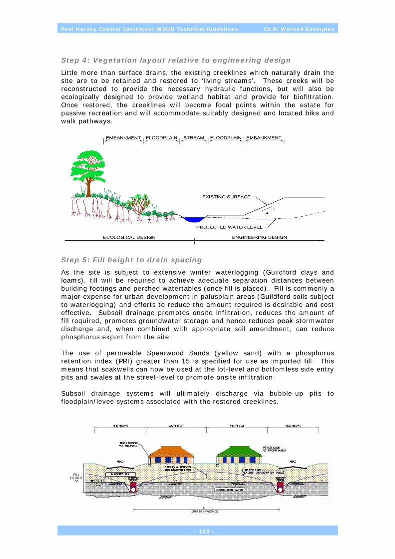
Peel Harvey Coastal Catchment WSUD Technical Guidelines Ch 8: Worked Examples
Step 4: Vegetation layout relative to engineering design
Little more than surface drains, the existing creeklines which naturally drain the site are to be retained and restored to ‘living streams’. These creeks will be reconstructed to provide the necessary hydraulic functions, but will also be ecologically designed to provide wetland habitat and provide for biofiltration. Once restored, the creeklines will become focal points within the estate for passive recreation and will accommodate suitably designed and located bike and walk pathways.
Step 5: Fill height to drain spacing
As the site is subject to extensive winter waterlogging (Guildford clays and loams), fill will be required to achieve adequate separation distances between building footings and perched watertables (once fill is placed). Fill is commonly a major expense for urban development in palusplain areas (Guildford soils subject to waterlogging) and efforts to reduce the amount required is desirable and cost effective. Subsoil drainage promotes onsite infiltration, reduces the amount of fill required, promotes groundwater storage and hence reduces peak stormwater discharge and, when combined with appropriate soil amendment, can reduce phosphorus export from the site. The use of permeable Spearwood Sands (yellow sand) with a phosphorus retention index (PRI) greater than 15 is specified for use as imported fill. This means that soakwells can now be used at the lot-level and bottomless side entry pits and swales at the street-level to promote onsite infiltration. Subsoil drainage systems will ultimately discharge via bubble-up pits to floodplain/levee systems associated with the restored creeklines.
- 102 -
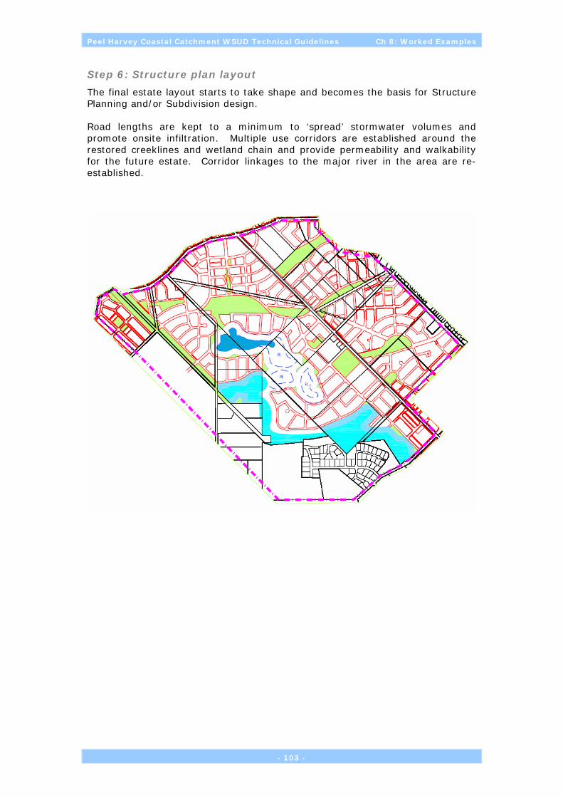
Peel Harvey Coastal Catchment WSUD Technical Guidelines Ch 8: Worked Examples
- 103 -
Road lengths are kept to a minimum to ‘spread’ stormwater volumes and promote onsite infiltration. Multiple use corridors are established around the restored creeklines and wetland chain and provide permeability and walkability for the future estate. Corridor linkages to the major river in the area are re-established.
The final estate layout starts to take shape and becomes the basis for Structure Planning and/or Subdivision design.
Step 6: Structure plan layout

Peel Harvey Coastal Catchment WSUD Technical Guidelines Ch 8: Worked Examples
- 104 -
Step 7: Final estate layout

Peel Harvey Coastal Catchment WSUD Technical Guidelines Ch 8: Worked Examples
8.2 Commercial
The following is a worked example which briefly outlines the buildup of information overlays and how this is used to derive an overall WSUD design philosophy. The sizing, location and number of structural controls is specific for any given site and the following designs are purely indicative and would need to be the subject of detailed site investigations and hydraulic modelling.
Step 1: Surface flow
The area has a history of drainage problems. Factors contributing to this include a high water table, clay subsoils and a relatively flat terrain. Topography for the site shows it can be effectively divided into two distinct surface water subcatchments.
- 105 -

Peel Harvey Coastal Catchment WSUD Technical Guidelines Ch 8: Worked Examples
Step 2: Soil profile & Step 3: Site classification zones
Contrary to the above surface water divide, geotechnical surveys determine that the subsoil clay surface across the site is uneven and slopes. This means shallow groundwater flows in a northerly direction. The surface and subsurface drainage systems therefore need to be considered with this mind.
Step 4: Sub-surface flow
Further geotechnical testing is undertaken across the site to determine the suitability of the onsite soils for the construction of building footings. Testing confirms the site comprises a thin veneer of Bassendean Sands (generally <1m) overlying Guildford clays.
- 106 -

Peel Harvey Coastal Catchment WSUD Technical Guidelines Ch 8: Worked Examples
Step 5: Road networks
Vehicular access to the commercial estate is important for the viability of the development. The major feeder road provides the conceptual ‘spine’ for the development and future drainage design. In major storms (>30 years) the roadway will become the flood outlet as the drainage system will inevitably backup. Two detention basins (B1 & B2) are required to achieve the 1:10 year pre-development stormwater retention design objective for a commercial estate.
- 107 -

Peel Harvey Coastal Catchment WSUD Technical Guidelines Ch 8: Worked Examples
Step 6: Flood paths and drain cross sections
As the site is subject to extensive winter waterlogging (Guildford clays and loams), fill will be required to achieve geotechnical requirements for building footings. Subsoil drainage is not possible because the quantities of fill that would be required across the site are prohibitively expensive. Some sand fill is, however, required to enable reshaping of the site surface contours to enable the surface drainage system to drain towards the outlet (at B2). The road hierarchy is designed and road lengths are kept to a minimum to reduce peak discharge rates as much as possible. Events grater than 1:10 year are designed to overspill basin B2 and inundate the low point of the site (an ephemeral wetland), rather than nearby properties. The frequency and duration of this inundation and quality of stormwater will not adversely impact the ephemeral wetland.
- 108 -

Peel Harvey Coastal Catchment WSUD Technical Guidelines Ch 8: Worked Examples
- 109 -
Single lane and divided road reserves are designed to incorporate biofiltration swales to promote onsite infiltration.
Step 7: Road networks and proposed finished levels

Peel Harvey Coastal Catchment WSUD Technical Guidelines Ch 8: Worked Examples
- 110 -
Step 8: Final estate layout
