guidance notes on the implementation of human … while reducing the potential for human error. ......
TRANSCRIPT

Guidance Notes on the Implementation of Human factors Engineering Design of Offshore Installations
GUIDANCE NOTES ON
THE IMPLEMENTATION OF HUMAN FACTORS ENGINEERING INTO THE DESIGN OF OFFSHORE INSTALLATIONS
JULY 2014
American Bureau of Shipping Incorporated by Act of Legislature of the State of New York 1862
Copyright 2014 American Bureau of Shipping ABS Plaza 16855 Northchase Drive Houston, TX 77060 USA

ii ABS GUIDANCE NOTES ON THE IMPLEMENTATION OF HUMAN FACTORS ENGINEERING INTO THE DESIGN OF OFFSHORE INSTALLATIONS . 2014
F o r e w o r d
Foreword Offshore companies, along with many other maritime entities, are becoming increasingly aware of, and are responding to, the critical role of the human element as the root of effective safety standards and practices. As a result, during the last two decades, the offshore industry began to concentrate more on improving human performance and reducing human error as a way to enhance offshore safety. The effort to improve safety and human performance introduced the engineering discipline of Human Factors Engineering (HFE) to the offshore industry.
Despite the positive experiences and results from including HFE design practices and principles into offshore design projects, HFE has yet to become a widely accepted and fully integrated aspect of design projects.
These Guidance Notes on the Implementation of Human Factors Engineering into the Design of Offshore Installations provide a strategy for integrating and implementing HFE into the design process as a way to help improve human performance and personnel efficiency and reduce safety risks associated with working and living on offshore installations. This integration of HFE into a program and the human element into the design can also improve overall system performance.
To help promote the effective integration and implementation of HFE design principles throughout the various lifecycle phases of an offshore capital project, a well-defined approach is required. The objective of these Guidance Notes is to identify the relevant HFE activities that need to be executed effectively and efficiently by describing a plan to integrate HFE into existing project management systems.
These Guidance Notes can be used as a roadmap for a larger effort to promote the application and understanding of HFE principles and criteria in system design and operations to help improve personnel performance and safety while reducing the potential for human error. It should be noted that the guidance presented in this document is recommendatory. Compliance with these Guidance Notes is not required, although ABS strongly urges the principles to be adopted wherever feasible and tailored based on the size and scope of the project.
These Guidance Notes become effective on the first day of the month of publication.
Users are advised to check periodically on the ABS website www.eagle.org to verify that this version of these Guidance Notes is the most current.
We welcome your feedback. Comments or suggestions can be sent electronically by email to [email protected].

ABS GUIDANCE NOTES ON THE IMPLEMENTATION OF HUMAN FACTORS ENGINEERING INTO THE DESIGN OF OFFSHORE INSTALLATIONS . 2014 iii
T a b l e o f C o n t e n t s
GUIDANCE NOTES ON
THE IMPLEMENTATION OF HUMAN FACTORS ENGINEERING INTO THE DESIGN OF OFFSHORE INSTALLATIONS
CONTENTS SECTION 1 Overview of Human Factors Engineering and Its Implementation .... 1
1 Introduction ......................................................................................... 1 1.1 The ABS Human Factors Engineering/Ergonomics Model:
Elements that Enhance Human Performance and Safety ............... 2 2 Application .......................................................................................... 4 3 Scope .................................................................................................. 4
3.1 Section 2, “HFE Implementation Program Planning” ....................... 4 3.2 Section 3, “Human Factors Engineering Implementation
Program” ......................................................................................... 5 3.3. Appendices ...................................................................................... 5
FIGURE 1 ABS Human Factors Engineering/Ergonomics Model .............. 2
SECTION 2 HFE Implementation Program Planning ............................................... 6
1 General ............................................................................................... 6 2 Factors Critical to Successful HFE Implementation ........................... 6 3 Engage Critical Parties in the HFE Implementation Process ............. 6
3.1 Human Factors Engineering Practitioners ....................................... 6 3.2 The Company Who Will Operate ..................................................... 7 3.3 The Company Who Will Lease ........................................................ 8 3.4 The “Design Agent” Working for the Company ................................ 8 3.5 The “Design Agent” Working for the Construction Yard .................. 8 3.6 The Vendor/Manufacturer ................................................................ 8
4 Determine the Level of HFE Involvement ........................................... 8 4.1 Tradeoffs ......................................................................................... 8
5 Obtain Management Commitment ...................................................... 9 5.1 Creation of an HFE Foundation and Integration within the
Company ....................................................................................... 10 5.2 Creation of an Organized Company Management Structure to
Promote the Use of HFE ............................................................... 10 5.3 Equalization of HFE with other Engineering Disciplines ................ 11 5.4 Use of HFE Principles in Areas Other than Engineering Design ... 11 5.5 Cooperation between HFE and Operations/Maintenance
Personnel ...................................................................................... 12
iv ABS GUIDANCE NOTES ON THE IMPLEMENTATION OF HUMAN FACTORS ENGINEERING INTO THE DESIGN OF OFFSHORE INSTALLATIONS . 2014
6 Additional Critical Considerations ..................................................... 12 6.1 Mandate HFE in Design ................................................................. 12 6.2 Utilize Accepted HFE Standards.................................................... 12 6.3 Lessons Learned ........................................................................... 12
TABLE 1 HFE Involvement Survey .......................................................... 9 FIGURE 1 Organizational Location for HFE ............................................. 11
SECTION 3 Human Factors Engineering Implementation Program ..................... 13
1 Introduction ....................................................................................... 13 2 Lifecycle Phases ............................................................................... 13 3 Conceptual Design ............................................................................ 15
3.1 Task #1 – HFE Planning and Organization .................................... 15 3.2 Task #2 – Identify HFE Tasks and Prepare the HFE
Implementation Plan (HFEIP) ........................................................ 15 3.3 Task #3 – Assist in Review and/or Development of Early
Project Design Documents ............................................................ 16 3.4 Task #4 – Select or Develop the HFE Design Standards that
will be Applied to All Phases and Components of the Project ........ 17 3.5 Task #5 – Prepare/Present HFE Awareness Training Packages
for Project Management, Engineering, and Construction/ Fabrication Personnel .................................................................... 19
3.6 Task #6 – Create an HFE Tracking Database ............................... 20 3.7 Task #7 – Participate in Preparation of the Project Specification
or Statement of Work (SOW) for Contractor Support for the Design Agent for Preliminary and Detail Design Phases ............... 21
3.8 Task #8 – Evaluate the Design Agent-provided HFEPP ................ 22 3.9 Task #9 – Participate in Selection of the Design Agent ................. 23
4 Preliminary Design ............................................................................ 23 4.1 Task #10 – Select or Prepare HFE Design Aids ............................ 23 4.2 Task #11 – Conduct Design Reviews of Design Drawings ............ 24 4.3 Task #12 – Include HFE Design Standards into Vendor
Purchase Specifications ................................................................ 24 4.4 Task #13 – Conduct Special Studies ............................................. 26
5 Detail Design ..................................................................................... 30 5.1 Task #14 – Provide General HFE Design Inputs ........................... 31 5.2 Task #15 – Conduct Facility Labeling Program ............................. 31 5.3 Task #16 – Prepare or Review Operations and Maintenance
Manuals ......................................................................................... 32 5.4 Task #17 – Conduct Computer Aided Design (CAD) Reviews ...... 33
6 Construction, Fabrication, Installation, and Commissioning (CFIC) ............................................................................................... 34 6.1 Task #18 – Conduct Periodic Visits to the Construction Yard
and Vendor Fabrication Sites ........................................................ 34 6.2 Task #19 – Monitor Selected Engineering Tests to Identify HFE
Design Deficiencies ....................................................................... 34 6.3 Task #20 – Monitor Commissioning Activities to Identify HFE
Deficiencies ................................................................................... 35 6.4 Task #21 – Observe Facility Installation Activities to Identify
HFE Design Deficiencies ............................................................... 36
ABS GUIDANCE NOTES ON THE IMPLEMENTATION OF HUMAN FACTORS ENGINEERING INTO THE DESIGN OF OFFSHORE INSTALLATIONS . 2014 v
7 Operations ........................................................................................ 36 7.1 Task #22 – Follow-up Evaluation after Period of Operation .......... 36
8 General Task .................................................................................... 37 8.1 Task #23 – Prepare Progress Reports .......................................... 37
TABLE 1 Overview of HFE Tasks and Responsibilities ......................... 14
APPENDIX 1 References ............................................................................................ 38 APPENDIX 2 Acronyms and Abbreviations ............................................................. 39 APPENDIX 3 Example HFEIP ..................................................................................... 40
1 Human Factors Implementation Plan Overview ............................... 40 2 Background ....................................................................................... 40 3 HFEIP Tasks ..................................................................................... 41
3.1 Task #1 – Provide HFE Training to Project Design/Engineering/ Management Personnel ................................................................ 41
3.2 Task #2 – Review of Project Design Documentation/Basis for HFE Requirements ........................................................................ 41
3.3 Task #3 – Prepare HFE Design Aids for Use by Engineers and Designers ...................................................................................... 42
3.4 Task #4 – Develop an HFE Tracking Database ............................ 42 3.5 Task #5 – Review Engineering Drawings and Design
Documents .................................................................................... 43 3.6 Task #6 – HFE Issue Conflict Resolution Strategy/Procedure ...... 43 3.7 Task #7 – Review Equipment Commissioning List to Determine
HFE Review Priorities.................................................................... 44 3.8 Task #8 – Vendor Hardware Design/Procurement Packages ....... 44 3.9 Task #9 – Preparation of Stair, Ladder, Walkway, Handrail
Design Standard ............................................................................ 44 3.10 Task #10 – Participate in the Design of the Fire, Gas, and
General Alarm System .................................................................. 45 3.11 Task #11 – Participate in Risk and Hazard Studies/Meetings ....... 45 3.12 Task #12 – Participate in Special Design Studies ......................... 46 3.13 Task #13 – Update and Review Materials Handling Studies ......... 46 3.14 Task #14 – Participate in 3D CAD Reviews and Walkthroughs ..... 46 3.15 Task #15 – Participate in the Design of the Accommodation
Facilities ........................................................................................ 47 3.16 Task #16 – Participate in Various Control Room Designs ............. 47 3.17 Task #17 – Labeling Program ....................................................... 47 3.18 Task #18 – Conduct On-site Visits to Vendor Fabrication
Facilities ........................................................................................ 48 3.19 Task #19 – Conduct On-site Visits to Contractor Fabrication
Facilities ........................................................................................ 48 3.20 Task #20 – Participate in the Development of Training Devices
and Materials ................................................................................. 49 3.21 Task #21 – Write or Review Operations and Maintenance
Manuals ......................................................................................... 49 3.22 Task #22 – Prepare HFE Report for Submission to the
Company ....................................................................................... 49

vi ABS GUIDANCE NOTES ON THE IMPLEMENTATION OF HUMAN FACTORS ENGINEERING INTO THE DESIGN OF OFFSHORE INSTALLATIONS . 2014
3.23 Task #23 – Perform Manning Assessment Task Analysis ............. 50 3.24 Task #24 – Establish Communications Protocols .......................... 50 3.25 Task #25 – Abandon Ship Procedures and Other Emergency
Procedures .................................................................................... 50 4 Management, Organization, Submittals, and Schedule Required
to Accompany an HFEIP ................................................................... 51 4.1 Management and Organizational Issues ....................................... 51 4.2 Submittals ...................................................................................... 51 4.3 HFE Task Schedule ....................................................................... 51
APPENDIX 4 Example of a List of Vendor Supplied Equipment Requiring HFE
in Purchase Specifications .................................................................. 52 APPENDIX 5 HFE Statement to be Placed in Vendor Purchase Specifications
Packages ............................................................................................... 55

ABS GUIDANCE NOTES ON THE IMPLEMENTATION OF HUMAN FACTORS ENGINEERING INTO THE DESIGN OF OFFSHORE INSTALLATIONS . 2014 1
S e c t i o n 1 : O v e r v i e w o f H u m a n F a c t o r s E n g i n e e r i n g a n d I t s I m p l e m e n t a t i o n
S E C T I O N 1 Overview of Human Factors Engineering and Its Implementation
1 Introduction Understanding human capabilities and limitations is a primary means to overcome opportunities for human error. A significant amount of research has been conducted to identify the factors that shape and influence human behavior and performance in a work environment. These factors include such diverse issues as:
• How the workplace is designed
• Human-system interfaces (e.g., ease of use and accessibility)
• How employees are selected for particular jobs (e.g., knowledge, skill, and ability requirements)
• How job aids such as operational or maintenance manuals or procedures are written and/or illustrated
• Human-computer interaction
• Physical, visual, and auditory access for maintenance and operation
• How company policies and practices are presented to, and enforced on, the work force
• Training personnel and a myriad of other human behavioral and psychosocial issues that affect personnel performance.
The application of the results of this research to the design of tools, equipment, tasks, workplaces, procedures, hardware, software, the working environment, and even to company/organizational design, is known as Human Factors Engineering (HFE). Those who practice in this discipline are called Human Factors Engineers, Human Factors Professionals, or Ergonomists.
HFE is a unique and specialized engineering discipline that combines specific academic education and experience of the human’s behavioral (i.e., social, physiological, psychological) and physical (i.e., size, strength, endurance) capabilities and limitations with that of the traditional engineering requirements to produce a human-system interaction that maximizes the best of both. This discipline allows for the human and system to work safely and efficiently.
HFE has broad areas of specialization and applicability. Therefore, for the purpose of these Guidance Notes, the focus of HFE is a domain of specialization largely concerned with human anatomical, anthropometric, physiological, behavioral, and biomechanical capabilities and limitations as they relate to human activity and the human-technology environment.
There are several formal definitions of HFE, including the following by the International Ergonomics Association (2014):
“The scientific discipline concerned with the understanding of the interactions among humans and other elements of a system, and the profession that applies theory, principles, data, and methods to design in order to optimize human well-being and overall system performance”
Ergonomics, which is often synonymous with HFE in Europe, tends to focus on the biomechanical, physiological, and anthropometric capabilities and limitations that humans possess as they relate to the design of systems.

Section 1 Overview of Human Factors Engineering and Its Implementation
2 ABS GUIDANCE NOTES ON THE IMPLEMENTATION OF HUMAN FACTORS ENGINEERING INTO THE DESIGN OF OFFSHORE INSTALLATIONS . 2014
The general approach of HFE in mitigating human error in the workplace as a means to reduce risk to human performance and safety is as follows (in order of preference):
1. Design the workplace so that human error cannot occur.
2. Design the workplace so that if an error does occur the consequences can be mitigated to an acceptable level.
3. Provide training to prevent the error.
4. Provide hazard identification labels to warn personnel of possible hazard.
5. Write a procedure or create a company policy to attempt to prevent the error from occurring.
Proper design is the preferred approach, as it is the most preventative measure to take for workplace design. The driving force behind the inclusion of HFE in the design of any offshore installation is that efficient and safe operational performance starts with good design.
To conclude, integrating HFE design practices and principles that reflect human capabilities and limitations into a design project, as discussed in these Guidance Notes, will help result in installations that are more cost-effective, safer, and easier to operate and maintain. The earlier that HFE is integrated into a design cycle, the more cost-effective the HFE effort will become and the greater the potential impact on overall business performance.
1.1 The ABS Human Factors Engineering/Ergonomics Model: Elements that Enhance Human Performance and Safety Section 1, Figure 1, “ABS Human Factors Engineering/Ergonomics Model”, below, encapsulates four (4) high-level “elements” that influence safety and efficiency in job performance: vessel or offshore installation design and layout considerations, workplace ambient environmental elements, management and organizational issues related to operations, and the personnel who operate the vessel or offshore installation. Insufficient attention to any of these elements may adversely affect safety, productivity, and efficiency. It is important that these elements be at the core of any HFE implementation effort. The structure and selection of activities described herein help promote this model and associated elements.
FIGURE 1 ABS Human Factors Engineering/Ergonomics Model
Design& Layout
Am
bien
t
Envi
ronm
ent
People
Man
agem
ent
& Org
aniza
tion

Section 1 Overview of Human Factors Engineering and Its Implementation
ABS GUIDANCE NOTES ON THE IMPLEMENTATION OF HUMAN FACTORS ENGINEERING INTO THE DESIGN OF OFFSHORE INSTALLATIONS . 2014 3
1.1.1 Management and Organizational Considerations This aspect of the model covers management and organizational considerations that impact human performance and safety throughout a system’s lifecycle. The implementation of an effective design and safety policy that includes human factors engineering and ergonomics will help create an environment that helps to minimize risks and reflects a good corporate safety culture for both system operations and to personnel. The commitment of top management is essential if this policy is to succeed. This commitment throughout the lifecycle means that it begins in early development with adequate resources to address HFE in design as well as the policy and personnel management required once the installation is operational.
In 1993, a study performed by the University of California at Berkeley found that 80% of all offshore accidents in U.S. waters were due to human error, and 80% of those occurred during operations. In 1995, the USCG launched a major initiative, called Prevention-Through-People (PTP), to reduce human error as a causative factor in maritime accidents when its research found that from 75-90% of all at-sea accidents were human-induced. This report also introduced the term “human element” to describe those factors which cause or contribute to human error. The preceding statistics illustrate the importance of the management considerations and commitment to implementing a comprehensive HFE program from inception through operations in order to achieve the human performance and safety goals.
1.1.2 Design and Layout Considerations Design and layout considerations include those related to the interfaces between personnel (users, operators, maintainers) and equipment or systems. Examples of interfaces include: controls, displays, alarms, video-display units, computer workstations, labels, ladders, stairs, and overall workspace arrangement. For additional design and layout considerations, refer to the ABS Guidance Notes on the Application of Ergonomics to Marine Systems.
Designers and engineers should consider the ultimate user’s cultural, psychological, and physiological capabilities, limitations, and needs that may impact work performance. In terms of cultural and regional influences on personnel’s behavioral patterns and expectations, this includes understanding that there are different cultural meanings with regard to color, control movement compatibility, or that bulky clothing is needed when using equipment in cold weather. As a result, hardware and software design, arrangement, and orientation must match the associated characteristics and expectations of the users.
Awareness of potential physical differences (e.g., male/female, tall/short, Northern European versus Southeast Asian) is required so that the design, arrangement, and orientation of the work environment will reflect the full range of personnel given the characteristics of the users and the required tasks.
The likelihood of human error may be increased if these factors are not considered in the workplace design. Additional training, operations and maintenance manuals, and more detailed written procedures cannot adequately compensate for human errors induced by poor design.
1.1.3 Ambient Environment Considerations The ambient environment addresses the habitability and occupational health characteristics related to human whole-body vibration, noise, indoor climate, and lighting. Substandard physical working and living conditions can undermine effective performance of duties, causing stress and fatigue. For example, working conditions that include high noise workplaces may lead to ineffective voice communications. Ambient environmental considerations also include the appropriate design of living spaces that assist in recovery from fatigue. For additional information on ambient environmental considerations, refer to the ABS Guide for Crew Habitability on Offshore Installations or the ABS Guide for Crew Habitability on MODUs.
1.1.4 Considerations Related to People Personnel readiness and fitness-for-duty are essential for safety. These are especially important as tasks and equipment increase in complexity, requiring ever-greater vigilance, skills, and experience. The following factors should be considered when selecting personnel for a task:
Section 1 Overview of Human Factors Engineering and Its Implementation
4 ABS GUIDANCE NOTES ON THE IMPLEMENTATION OF HUMAN FACTORS ENGINEERING INTO THE DESIGN OF OFFSHORE INSTALLATIONS . 2014
• Knowledge, skills, and abilities that stem from an individual’s basic knowledge, general or specialized training, and experience
• Bodily dimensions (anthropometrics) and characteristics of personnel such as stature, shoulder breadth, eye height, functional reach, overhead reach, weight, and strength
• Physical stamina; physiological capabilities and limitations, such as resistance to and freedom from fatigue, visual acuity, physical fitness, and endurance
• Psychological characteristics, such as individual tendencies for risk-taking behavior, risk tolerance, and resistance to psychological stress.
Choosing the correct personnel for the job or task is critical to overall safety and performance. Selection of personnel who do not have the requisite skills, training, or tools can adversely affect safety by reducing personnel efficiency and increasing the potential for error. While the focus of these Guidance Notes is affecting design to accommodate the capabilities and limitations of the intended users, the factors listed above need to be considered when defining the ultimate user population.
2 Application These Guidance Notes present a strategy for the integration and implementation of HFE into the design of offshore installations and introduce general criteria that need to be considered throughout the various lifecycle phases. This strategy can be applied to fixed and floating installations, offshore terminals, or any other facility created for exploration, production, distribution, and/or transportation of natural gas and oil anywhere in the world. It is also applicable to any level of project design from new installation design and construction to existing facility expansion, modernization or upgrading.
3 Scope The intended users of these Guidance Notes are HFE professionals with adequate education, training, and experience in the HFE profession, with particular expertise in offshore installations.
These Guidance Notes can be used as a roadmap for a larger effort to promote the application and understanding of HFE principles and criteria in system design and operations to help improve personnel performance and safety while reducing the potential for human error.
These Guidance Notes are a companion document to the existing ABS suite of human factors engineering-related documents such as the ABS Guidance Notes on the Application of Ergonomics to Marine Systems, The ABS Guide for Ergonomic Notations, and the various Guides for Crew Habitability. All of these documents can be downloaded free-of-charge from the ABS website (www.eagle.org).
These Guidance Notes address issues and concerns of HFE integration strategies and focus on specific implementation strategies that have been shown to be successful. The following Sections in these Guidance Notes cover the following:
3.1 Section 2, “HFE Implementation Program Planning” This Section discusses a strategy necessary to establish an HFE Implementation Program. This includes:
• Plan for conceptual, early, and continuous use of HFE throughout all phases of the project.
• Engage academically-educated and experienced HFE professionals as well as other individuals critical to the success of the program.
• Determine level of HFE involvement.
• Obtain management commitment to HFE and appoint an HFE Champion.
• Require close cooperation between HFE, Operations/Maintenance, and other engineering disciplines throughout the entire lifecycle.
• Mandate HFE in the project design.
Section 1 Overview of Human Factors Engineering and Its Implementation
ABS GUIDANCE NOTES ON THE IMPLEMENTATION OF HUMAN FACTORS ENGINEERING INTO THE DESIGN OF OFFSHORE INSTALLATIONS . 2014 5
• Require use of accepted HFE design standards in project specifications.
• Provide early focus on known HFE problem areas/lessons learned from other offshore facilities.
3.2 Section 3, “Human Factors Engineering Implementation Program” This Section discusses the strategy to run an HFE Implementation Program by outlining the HFE tasks that are typically performed on offshore design projects in the respective phase of design or construction. These project phases include:
• Conceptual Design
• Preliminary Design
• Detail Design
• Construction/Fabrication//Installation/Commissioning
• Operation
3.3. Appendices • Appendix 1 References
• Appendix 2 Acronyms and Abbreviations
• Appendix 3 Example HFEIP
• Appendix 4 Example List of Vendor Supplied Equipment Requiring HFE in Purchase Specifications
• Appendix 5 Example HFE Statement to be placed in Vendor Purchase Specifications Packages

6 ABS GUIDANCE NOTES ON THE IMPLEMENTATION OF HUMAN FACTORS ENGINEERING INTO THE DESIGN OF OFFSHORE INSTALLATIONS . 2014
S e c t i o n 2 : H F E I m p l e m e n t a t i o n P r o g r a m P l a n n i n g
S E C T I O N 2 HFE Implementation Program Planning
1 General This Section discusses the strategies and considerations necessary to plan, establish, and operate an HFE Implementation Program. This includes specific commitments that should be made in order to achieve program success, activities undertaken in planning stages, as well as the personnel who should be involved in the implementation process and their roles and responsibilities.
2 Factors Critical to Successful HFE Implementation Critical factors for the integration of HFE during the design’s lifecycle include:
• The use of HFE throughout all phases of the project
• Engaging qualified HFE professionals
• Determining the level of HFE involvement
• Management commitment to HFE and the appointment of an HFE Champion
• Close cooperation between HFE, Operations/Maintenance, and other engineering disciplines
• Mandating HFE in the project design
• Requiring use of accepted HFE design standards in project specifications
• Providing early focus on known HFE problem areas/lessons learned from other offshore facilities
3 Engage Critical Parties in the HFE Implementation Process There are potentially six (6) groups who may be involved in applying HFE to the design of any offshore facility. These include:
i) HFE practitioners
ii) The “Company” who will operate the facility
iii) The lessee
iv) Design agents
v) The construction yard(s)
vi) Product vendors/manufacturers
All of these groups can influence the effectiveness of the implementation of HFE. These different groups along with their responsibilities are discussed below.
3.1 Human Factors Engineering Practitioners Human factors engineering is an engineering discipline concerned with the interactions among humans and systems and requires academic training typically not found in more traditional engineering disciplines. The Subparagraphs below list basic qualifications that the HFE professional should possess.
Section 2 HFE Implementation Program Planning
ABS GUIDANCE NOTES ON THE IMPLEMENTATION OF HUMAN FACTORS ENGINEERING INTO THE DESIGN OF OFFSHORE INSTALLATIONS . 2014 7
3.1.1 Education The Human Factors Practitioner should have an advanced degree in engineering or psychology with emphasis in human factors, human factors engineering, or ergonomics.
3.1.2 Work Experience • Preferably at least five (5) years of HFE experience in the design of heavy industrial facilities
(e.g., offshore, refineries, paper mills, cement plants, chemical plants, shipbuilding)
• Preferably two (2) years of supervisory experience in a development project
• Desired areas of HFE design expertise:
- Access aids such as stairs, ladders, walkways, work platforms, ramps, manways
- Control/display/alarm design and integration
- Console and control panel design, arrangement, and orientation
- Design for enhanced maintainability of a complete facility and individual equipment
- Design for ease of manual material handling
- Design and selection of material handling equipment and operations
- Familiarity with, and experience in, use of HFE design standards
- Knowledge of human social, psychological, and physiological needs, and capabilities and limitations as applied to the workplace
- Knowledge of labeling design standards
- Knowledge of maritime crew habitability requirements and standards
3.1.3 Licensing/Certifications: Professional certifications/licensing are preferred based on the level of involvement of the HFE professional in the design of the facility, but are not required. Ideally, the HFE professional should either possess or have the requisite experience and qualifications to be eligible to obtain a professional certification from a certifying organization such as:
• Board of Certification in Professional Ergonomics (BCPE)
• Canadian College for the Certification of Professional Ergonomists (CCCPE)
• Japan Ergonomics Society Certified Professional Ergonomists (JES CPE)
• Centre for Registration of European Ergonomists (CREE)
3.2 The Company Who Will Operate The Company initiates, pays for, owns the project, and will operate the facility as a part of the Company’s total assets. For example, an exploration and production (E&P) company may build a new drilling and production platform for installation in the North Sea. In this case, the Company has the final say on if, and how much, HFE input will be incorporated during the facility’s design, and who will be the principal HFE provider. The actual implementation of HFE can then be achieved in one of three (3) ways:
i) The Company can utilize an in-house HFE expert or hire an HFE professional to complete all the HFE tasks found necessary by the Company, design agent, construction yard, and vendors from conceptual design to operational phases.
ii) The Company can require the design agent to utilize the services of an HFE professional who works for the design agent only.
iii) The Company can hire an HFE professional consultant to periodically evaluate the engineers’ HFE efforts, usually near the end of the detail design phase.
All three approaches are ranked in order of effectiveness, with the first (an HFE professional to perform all tasks) being the most effective.
Section 2 HFE Implementation Program Planning
8 ABS GUIDANCE NOTES ON THE IMPLEMENTATION OF HUMAN FACTORS ENGINEERING INTO THE DESIGN OF OFFSHORE INSTALLATIONS . 2014
3.3 The Company Who Will Lease A Company initiates, pays for, owns the project, and may even operate it, but does so under a lease arrangement to another Company (e.g., an independent E&P company). For example, a drilling company may design and build a new drilling rig based on a multi-year lease with an E&P company. In this case, both the drilling and E&P companies may have specific design requirements they wish to be incorporated into the new design, including HFE. Typically, the lessee (i.e., the E&P Company) will have more influence on the implementation of HFE.
3.4 The “Design Agent” Working for the Company It is common that an outside marine engineering or naval architectural company (design agent) will be hired to assist with the facility design. In these instances, the Company has the responsibility to advocate HFE representation during design. The Company can take the lead to provide HFE professionals or they can oversee the HFE efforts performed by the design agent’s HFE professionals.
3.5 The “Design Agent” Working for the Construction Yard In some instances, the design agent’s role has been filled by the “construction yard”. Most large construction yards possess their own design engineers who serve as the design agent for the detailed design. The yard’s engineers would then be responsible for the inclusion of HFE into the design. In these instances, the Company has the responsibility to recommend that there is HFE representation during design. The Company can take the lead to provide HFE professionals or they can oversee the HFE effort completed by the construction yard’s HFE professionals.
3.6 The Vendor/Manufacturer The last group that plays an important role in the application of HFE is the vendors and manufacturers who make or supply equipment for the project. It is unusual for a vendor or manufacturer to employ HFE professionals, so the Company has the responsibility to recommend that HFE design requirements are included in the original vendor bid specification and that vendors and manufacturers comply with this bid specification.
4 Determine the Level of HFE Involvement A reasonable question to ask is whether or not HFE should be involved in a project, and if so, to what level. It is understood that projects can range from simple (e.g., replacement of piping, or simply adding another piece of equipment, skid, or process train that already exists in the system to increase production rates), to intermediate (e.g., adding a new system to an existing one), to major (e.g., the design and construction of a new offshore drilling rig or production platform). As a result, HFE may not be needed for every design project or, if needed, may be limited in the HFE tasks required because the project does not warrant extensive HFE involvement. However, it is suggested that an HFE evaluation be completed for all proposed capital projects to assist the Project Manager in determining if, and/or to what level, HFE should be involved.
As a guide to help determine HFE involvement, the following survey has been developed (see Section 2, Table 1, “HFE Involvement Survey”). A “YES” answer to one or more of the questions indicates that there should be some HFE involvement. In addition to this survey, the required level of HFE involvement should be reviewed by a qualified HFE Practitioner.
4.1 Tradeoffs In the practice of applying HFE principles in design, an ongoing process of considering tradeoffs will occur within and among the elements of the ABS Ergonomic Model described previously in Section 1, Figure 1.
Tradeoffs allow for compensation across these domains to provide an appropriate level of human performance and safety. Ergonomic design of human-system interfaces will influence job complexity, which in turn affects personnel knowledge, skill requirements, training requirements, etc. There are other significant factors contributing to the outcome of tradeoff decisions, including:
i) Cost (e.g., engineering, construction, commissioning, operating, decommissioning)
ii) Risk tolerance (e.g., business, human safety, environmental, technical, financial, societal reputation)
iii) Statutory (e.g., laws and agreements that govern functionality and design)
iv) Competitiveness

Section 2 HFE Implementation Program Planning
ABS GUIDANCE NOTES ON THE IMPLEMENTATION OF HUMAN FACTORS ENGINEERING INTO THE DESIGN OF OFFSHORE INSTALLATIONS . 2014 9
Human element and ergonomic concerns should have a competitive status with regard to other tradeoff elements.
TABLE 1 HFE Involvement Survey
No. Question YES NO
1 Will the type of personnel involvement or the philosophies related to operation or maintenance of the new design or equipment differ substantially from the current practice of the company?
2 Will the new design, equipment, instrumentation, etc., introduce new technologies or automation and impose new tasks and skill requirements on the operators/maintainers not previously required?
3 Is there an opportunity to decrease operator/maintainer levels of error through improved design?
4 Will the design be operated/maintained by individuals not normally assigned to work on the facility (e.g., outside personnel, contractors, vendor equipment repair specialists)?
5 Is one of the objectives of the new project to reduce manning levels?
6 Will the new design be used by personnel from a culture or geographic part of the world different than the individuals doing the actual designing and/or construction?
7 Will the new design be operated or maintained by both men and women?
8 Will the new design be provided with equipment or systems with which the operators/maintainers have had little or no previous experience?
9 Is one of the goals of the new design to reduce accidents or incidences that have occurred on other facilities?
10 Will the new design be significantly more complex than, or different from, any previously operated by the company?
11 Is the new design a result of issues associated with HFE?
12 Is one of the goals of the new project specifically to reduce operating/maintenance costs?
13 Does the company have a specific corporate mission to enhance safety and quality of the work environment for its employees?
14 Has the company had any previous unfavorable rulings from regulatory agencies on issues of employee safety, pollution control, or facility design based on HFE issues?
Total # of “Yes” Answers __________
5 Obtain Management Commitment Management commitment to HFE is a crucial program element for successful integration of HFE into the overall design process for any offshore design project. Management commitment to HFE can be exhibited in several ways. These include:
• Creation of an HFE foundation and integration within the Company
• Creation of an organized management structure to promote the use of HFE
• Equalization of HFE with other engineering disciplines
• Requiring use of HFE principles in areas peripheral to direct engineering design, such as personnel selection, staffing levels, shift work, preparation of procedures, operation and maintenance manuals, and setting physical work environments
• Close cooperation between HFE and operations and maintenance personnel.

Section 2 HFE Implementation Program Planning
10 ABS GUIDANCE NOTES ON THE IMPLEMENTATION OF HUMAN FACTORS ENGINEERING INTO THE DESIGN OF OFFSHORE INSTALLATIONS . 2014
5.1 Creation of an HFE Foundation and Integration within the Company An imperative first step is the creation of a corporate foundation for the successful integration of HFE throughout the phases of a capital design project. This is accomplished through the commitment of Company management for, and belief in, the value of HFE. This commitment should be exhibited as an obvious and normal part of doing everyday business and should also officially be established as a guiding principle within the Company’s operating philosophy document or expressly stated in corporate policies, practices, or procedures such as in the Company’s vision, mission, and/or objective statements. Examples of an HFE vision, mission statement, and objective statement that could be incorporated into a Company’s operating philosophy or policy document are as follows:
5.1.1 Vision To improve overall system performance and reliability in all company facilities and businesses by optimizing personnel performance, health, and safety through effectively integrating human factors engineering principles into the lifecycle of design projects.
5.1.2 Mission To manage and integrate human factors engineering through all phases of the project lifecycle in order to minimize the potential for human error and optimize operability and maintainability during facility operation.
5.1.3 Objectives Objectives for human factors engineering implementation include:
• Verifying management and line responsibility and resources for human factors engineering implementation within a project team
• Establishing accountability for implementation of human factors engineering within the project team.
• Verifying human factors engineering activities and tasks are effectively integrated into the project schedule for all major project phases.
• Creating awareness of human factors engineering at all levels of a project team including its design agents, construction contractors, and vendors.
• Commitment for demonstrating the economic and health, safety, and environmental (HSE) benefits from applying human factors engineering.
Establishing such philosophies as a corporate value, and requiring HFE appearance in each specific design project management document as a requirement (signed by the Project Manager, Chief Engineer, the HFE Champion and the HFE Professional) sets the stage for conveying to all personnel within an organization, including individual project teams, and contracted organizations or personnel, that HFE is a requirement that should not be omitted, minimized or subjected to subjugation to other engineering disciplines.
5.2 Creation of an Organized Company Management Structure to Promote the Use of HFE The second way to demonstrate management commitment to HFE is to establish management and line responsibility for HFE within the Company as a whole and within each specific design project team. Project management should physically and organizationally locate the HFE activity such that it promotes interaction between HFE, Engineering, Operations, and Health, Safety and Environmental (HSE). Past experience has shown that a preferred location for HFE is with the Engineering function and with Operations as a good second choice. An example of an organizational location for HFE is shown in Section 2, Figure 1, “Organizational Location for HFE”.

Section 2 HFE Implementation Program Planning
ABS GUIDANCE NOTES ON THE IMPLEMENTATION OF HUMAN FACTORS ENGINEERING INTO THE DESIGN OF OFFSHORE INSTALLATIONS . 2014 11
FIGURE 1 Organizational Location for HFE
ProjectManagement
HSEManager
HFEFunction
OperationsManager
EngineeringManager
(HFE Champion)
EngineersDesigners
CAD Operators
As a part of this management organization, there should be a Company HFE Champion. This individual represents the HFE discipline and symbolizes the bridge between HFE and the other project team members. This individual should be located within the engineering department (for the Company) and the project design team (for individual projects). This person should have Company or project approval authority on all design, installation, and commissioning-related issues where there is a human component in the system, and it is suggested HFE be considered on an equal basis with the other engineering disciplines. In addition, the HFE Champion should have sufficient influence within the Company and project team to be able to direct engineering work and effect change.
The value of the “HFE Champion” has been amply and consistently demonstrated on past offshore capital design projects and should be actively involved in any Company and individual design project if HFE success is desired. This individual should be someone with an interest and understanding of HFE, and possess a human factors engineering background. The HFE Champion should not be responsible for performing the HFE tasks but should be the spokesperson for HFE within the rest of the Company or with the specific project. In addition, the HFE Champion should have final decision authority regarding all HFE issues if a conflict should arise between the HFE requirements and other design standards in the project design team.
5.3 Equalization of HFE with other Engineering Disciplines The third action to demonstrate management commitment to HFE is to provide the same management oversight of, and attention to, HFE with the same enthusiasm and scrutiny as is provided to the other engineering disciplines. HFE requirements should be as important as any other engineering discipline and be given equal consideration in all design decisions. HFE should be expected to define its activities, successes, setbacks or shortcomings, and overall progress, and should be required to do so at all in-house or customer-based project design review meetings. It should not be required to justify its presence in a design project (economically or technically) any more or any less than any of the other engineering specialties.
5.4 Use of HFE Principles in Areas Other than Engineering Design Company and project management should show their commitment to HFE through the utilization of knowledge and information in areas outside of HFE (e.g., in the conceptual design stage, be involved in the establishment of manning, safety, operations, and maintenance philosophies) and create a working environment that encourages inter-personal interaction among all levels of personnel and establish an organizational structure that provides communication and cooperation between all levels of the company.

Section 2 HFE Implementation Program Planning
12 ABS GUIDANCE NOTES ON THE IMPLEMENTATION OF HUMAN FACTORS ENGINEERING INTO THE DESIGN OF OFFSHORE INSTALLATIONS . 2014
5.5 Cooperation between HFE and Operations/Maintenance Personnel The input from the expected users, usually represented by operations and maintenance personnel, is critical to the successful integration of HFE into the design of any offshore facility, and should be sought during every phase of the design cycle beginning with the conceptual design phase. By obtaining the opinions and knowledge of those who have a working experience with systems, equipment, and facilities similar to those under design, valuable lessons learned can be incorporated into the current design project. In addition, experience has clearly shown that when users are a part of the design team on a new project, their satisfaction with the finished facility increases.
The cooperation between operations and maintenance personnel and HFE professionals is critical to determining many of the design parameters and in the development of many project documents, such as operating and maintenance manuals and procedures. Operations and maintenance personnel provide specific details covering operation and maintenance task requirements that will be translated into the project design standards and guidelines, as well as being integrated into personnel competency profiles, staffing levels, HAZID (Hazard Identification) and HAZOP (Hazards and Operability) studies, materials handling, and valve criticality studies.
A close working relationship between HFE professionals and operators and maintainers requires that they be organizationally and physically located together (same design facility) to help facilitate a close affiliation.
6 Additional Critical Considerations In addition to the foundation that management commitment and an appropriate organizational structure can provide, additional considerations for the implementation of the HFE program rest in the technical aspects that should be reflected in the design of the facility. These can be derived from industry standards, best practices, and from lessons learned from similar predecessor systems.
6.1 Mandate HFE in Design Like any other technical specifications, HFE requirements should be included, imposed, and enforced.
6.2 Utilize Accepted HFE Standards Accepted HFE standards for marine systems contain the appropriate considerations with measurable and verifiable criteria applicable to the design of offshore facilities. These standards, listed below, can either be referenced in their entirety in the contractual specifications or used as a basis for a project-specific HFE design standard tailored for criteria that only apply to the system to be designed:
• Standard Practice for Human Engineering Design for Marine Systems, Equipment, and Facilities, Standard F1166. American Society of Testing and Materials (ASTM). (2007)
• Standard Human Engineering Program Requirements for Ships and Marine Systems, Equipment and Facilities, Standard 1337. American Society of Testing and Materials (ASTM) (2010)
• Guide for Ergonomic Notations. American Bureau of Shipping
• Guide for Crew Habitability on MODUs. American Bureau of Shipping
• Guide for Crew Habitability on Offshore Installations. American Bureau of Shipping
• Guidance Notes on the Application of Ergonomics to Marine Systems. American Bureau of Shipping
• Guidance Notes on Ergonomic Design of Navigation Bridges. American Bureau of Shipping
• Common requirements, architectural components & equipment (C-CR-002). Norwegian Oil Industry Association and the Federation of Norwegian Engineering Industries (NORSOK). (1996)
• Working environment (S-002). Norwegian Oil Industry Association and the Federation of Norwegian Engineering Industries (NORSOK). (2004).
6.3 Lessons Learned Any historical data related to human performance and safety issues can provide a wealth of information for follow-on designs and can help prevent past incidents and accidents from re-occurring.

ABS GUIDANCE NOTES ON THE IMPLEMENTATION OF HUMAN FACTORS ENGINEERING INTO THE DESIGN OF OFFSHORE INSTALLATIONS . 2014 13
S e c t i o n 3 : H u m a n F a c t o r s E n g i n e e r i n g I m p l e m e n t a t i o n P r o g r a m
S E C T I O N 3 Human Factors Engineering Implementation Program
1 Introduction Appropriate planning based on the information in Section 2, “HFE Implementation Program Planning” is critical in an effective HFE Implementation Program. An effective program includes numerous HFE tasks. These tasks comprise the program itself depending on the phase of development and the scale or scope of the project. HFE activities should be conducted as early as possible in the project’s lifecycle so as to have the most impact on the design rather than after the detailed design of equipment and workplaces has begun.
Successful application of HFE depends on a proper process of conducting the appropriate activities in the various stages of the project’s development lifecycle. This Section describes the phases of development for a project, the typical HFE tasks that are conducted, and the responsible parties for the tasks.
2 Lifecycle Phases Traditionally, the design process for any new or modified offshore facility encompasses several phases of design, construction, commissioning, on-site installation, start-up, and operation. Precisely how the lifecycle is divided into phases and the designations given to stages varies from project to project, but the objectives and outputs of the phases should be similar.
The actual number of phases is determined by the complexity of the project, whether it is a new facility or a modification of an existing one, and the reasons that the work is being done. Further, the number, names, and composition of each phase, especially during design, vary. However, for these Guidance Notes, the phases are identified as:
• Conceptual Design (CD) – In this phase, the project recognizes the systems needed, determines one or more appropriate options that meet the need, and decides which option(s) to develop further. During this phase, project goals are established and facilities’ performance requirements are determined.
• Preliminary Design (PD) – The conceptual design is increased in detail, with systems and individual pieces of equipment shown to scale and in their proposed layout, location, and arrangement within the facility. The goal of the preliminary design phase is to establish a proposed configuration that meets the project’s performance requirements and that shows enough detail so the proposed arrangement and configuration can be adequately judged to progress to the next phase of the design process (i.e., detail design).
• Detail Design (DD) – The facilities to be implemented are defined both in functional and physical terms and have the detailed requirements for implementation/construction.
• Construction, Fabrication, Installation, and Commissioning (CFIC)
- Construction/Fabrication – Implementing the design and delivery of the physical systems that are ready for on-site installation.
- Commissioning and On-site Installation – Realizing the physical system and making it ready for operation.
• Operation – Using the facility for its intended purpose, and supporting it so that it continues to operate.
The lifecycle stage of decommissioning is not covered in these Guidance Notes because there is very limited HFE experience/activity in this area at the current time.

Section 3 Human Factors Engineering Implementation Program
14 ABS GUIDANCE NOTES ON THE IMPLEMENTATION OF HUMAN FACTORS ENGINEERING INTO THE DESIGN OF OFFSHORE INSTALLATIONS . 2014
Section 3, Table 1, “Overview of HFE Tasks and Responsibilities”, and Subsections 3/3 through 3/8 thoroughly map out and describe the different HFE tasks that may need to be conducted. There are twenty three (23) different HFE-related tasks that can be performed. Each task is identified by the different lifecycle phases in which it normally occurs.
The tasks are listed in the order in which they would normally occur (and should be conducted) in a major capital design project. By no means are all tasks listed here expected to be conducted, especially for smaller projects or facility modernization efforts, but rather the approach should be tailored appropriately. This tailoring should be performed by an experienced HFE Practitioner.
For the purposes of Section 3, Table 1, “Overview of HFE Tasks and Responsibilities”, the “X” represents the lifecycle stage(s) in which the task would typically occur. The responsible party for each task is specific to each project. The responsibilities are determined by who is conducting the HFE effort (i.e., the Company, design agent, etc.).
TABLE 1 Overview of HFE Tasks and Responsibilities
Task No. Task Description
Project Lifecycle Phase Concept Preliminary Detail CFIC Operation
1 HFE Planning and Organization X 2 Identify HFE Tasks and Prepare the HFE Integration Plan (HFEIP) X
3 Assist in Review and/or Development of Early Project Design Documents X
4 Select or Develop the HFE Design Standards that will be Applied to all Phases and Components of the Project X
5 Prepare/Present HFE Awareness Training Packages for Project Management, Engineering, and Construction/Fabrication Personnel X X X X
6 Create an HFE Tracking Database X
7 Participate in Preparing the Project Specification or Statement of Work (SOW) for Contractor Support for the Design Agent for Preliminary and Detail Design Phases
X
8 Evaluate the Design Agent-provided HFEIP X 9 Participate in Selection of the Design Agent X 10 Select or Prepare HFE Design Aids X X 11 Conduct Design Reviews of Design Drawings X X 12 Include HFE Design Standards into Vendor Purchase Specifications X X 13 Conduct Special Studies X X 14 Provide General HFE Design Inputs X X X X 15 Conduct Facility Labeling Program X X 16 Prepare or Review Operations and Maintenance Manuals X X 17 Conduct Computer Aided Design (CAD) Reviews X X X
18 Conduct Periodic Visits to the Construction Yard and Vendor Fabrication Sites X
19 Monitor Selected Engineering Tests to Identify HFE Design Deficiencies X
20 Monitor Commissioning Activities to Identify HFE Deficiencies X
21 Observe Facility Installation Activities to Identify HFE Design Deficiencies X
22 Follow-up Evaluation After Period of Operation X 23 Prepare Progress Reports X X X X
Section 3 Human Factors Engineering Implementation Program
ABS GUIDANCE NOTES ON THE IMPLEMENTATION OF HUMAN FACTORS ENGINEERING INTO THE DESIGN OF OFFSHORE INSTALLATIONS . 2014 15
3 Conceptual Design In the conceptual design phase, the Company establishes project needs and goals for the system to be designed, evaluates the various options open to them in terms of facility design such as the basic configuration (e.g., TLP vs. SPAR for a new deepwater offshore platform), sets operating limits such as water depth, well depth and number of wells (for drilling rigs), forecasts production rates (barrels of oil or cu-ft of gas) that in turn defines facility performance requirements, estimates crew size, and identifies types and resources for key equipment such as for propulsion (for a MODU), power generation, riser tensioners, pipeline pumps, and fire fighting equipment.
During this phase, a decision should be made by the Company as to who will represent the HFE discipline in this design project. In keeping with the general philosophy that each of the technical disciplines should be represented by persons educationally trained and experienced, it is recommended that all HFE activities throughout the design project be performed by an HFE Practitioner.
The following Paragraphs represent the HFE tasks that should be performed during the conceptual design phase of a project. For each task, a summary table is provided which identifies the design phase, any input into the task (from other HFE tasks), output of the task’s deliverables, and high level comment(s) about the task.
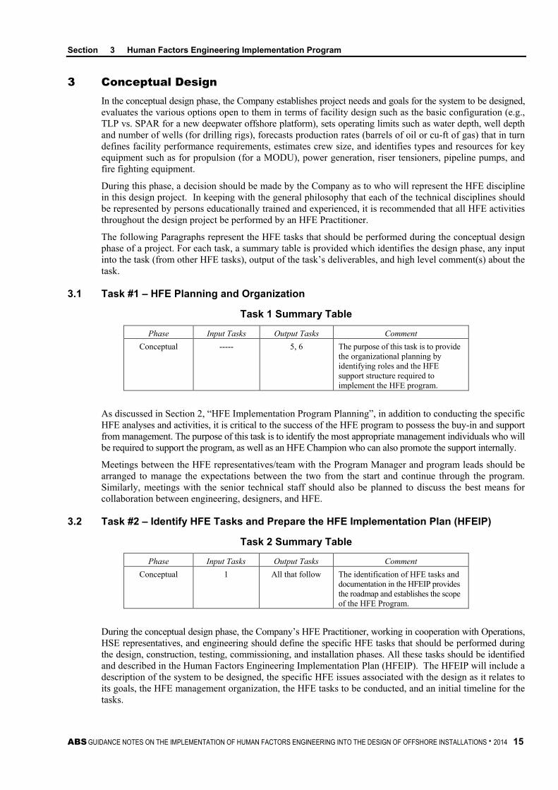
3.1 Task #1 – HFE Planning and Organization
Task 1 Summary Table
Phase Input Tasks Output Tasks Comment Conceptual ----- 5, 6 The purpose of this task is to provide
the organizational planning by identifying roles and the HFE support structure required to implement the HFE program.
As discussed in Section 2, “HFE Implementation Program Planning”, in addition to conducting the specific HFE analyses and activities, it is critical to the success of the HFE program to possess the buy-in and support from management. The purpose of this task is to identify the most appropriate management individuals who will be required to support the program, as well as an HFE Champion who can also promote the support internally.
Meetings between the HFE representatives/team with the Program Manager and program leads should be arranged to manage the expectations between the two from the start and continue through the program. Similarly, meetings with the senior technical staff should also be planned to discuss the best means for collaboration between engineering, designers, and HFE.
3.2 Task #2 – Identify HFE Tasks and Prepare the HFE Implementation Plan (HFEIP)
Task 2 Summary Table
Phase Input Tasks Output Tasks Comment Conceptual 1 All that follow The identification of HFE tasks and
documentation in the HFEIP provides the roadmap and establishes the scope of the HFE Program.
During the conceptual design phase, the Company’s HFE Practitioner, working in cooperation with Operations, HSE representatives, and engineering should define the specific HFE tasks that should be performed during the design, construction, testing, commissioning, and installation phases. All these tasks should be identified and described in the Human Factors Engineering Implementation Plan (HFEIP). The HFEIP will include a description of the system to be designed, the specific HFE issues associated with the design as it relates to its goals, the HFE management organization, the HFE tasks to be conducted, and an initial timeline for the tasks.

Section 3 Human Factors Engineering Implementation Program
16 ABS GUIDANCE NOTES ON THE IMPLEMENTATION OF HUMAN FACTORS ENGINEERING INTO THE DESIGN OF OFFSHORE INSTALLATIONS . 2014
The HFEIP is of high importance since it defines in detail the proposed HFE program that will be performed during the project. Once approved by project management (the HFEIP will be signed by the Project Manager, HFE Champion, Head of Project Engineering, and the Company HFE Practitioner), it will serve as the roadmap which all project designers and engineers will follow in relation to the HFE program. The HFEIP will also serve as a means of communicating the expectations of the Company to the Design Agent and Construction Yard(s). As such, the HFEIP should be included in the Project Specification Document and/or the Design Philosophy Document. In addition, it can be placed, in part or in whole, in the Statement of Work (SOW) for the bid packages sent to those firms seeking to be the Design Agent, Construction Yard, and/or Vendors for the project.
Additionally, the specific tasks to be included in the HFEIP that are necessary to fully integrate HFE into the design project are listed and described in the following Paragraphs. However, there may be an occasion where a task not described here may be required (for example, safety and HFE issues related to piracy).
Any anticipated special studies that should be completed should also be included in the HFEIP. For example, a link analysis of the bridge or control room layout, a gross task analysis for the Dynamic Positioning Control System, or a valve criticality analysis, and any special HFE requirements such as special use of electronic models, or conduct of tests should be listed and described.
Once the tasks are identified, an initial schedule, tied to the overall project schedule, will show when each HFE task should commence and when it should be completed. The schedule will also identify who will be responsible for completing each task (e.g., the Company, Design Agent, Construction Yard, or Vendor).
A sample HFEIP for a fictitious international E&P new capital construction design project is provided in Appendix 3, “Example HFEIP”.
3.3 Task #3 – Assist in Review and/or Development of Early Project Design Documents
Task 3 Summary Table
Phase Input Tasks Output Tasks Comment Conceptual 1 and 2 4, 5, 6 Project documentation and lessons
learned from like systems can provide high-level HFE considerations or opportunities for proactive risk reduction.
HFE personnel working with the assistance of operational personnel should be a part of the project team during the conceptual design phase, and should participate in all project meetings or discussions involving personnel safety, productivity, and habitability. The HFE personnel can act as facilitators and representatives for the users (operational personnel) to aid in the implementation of appropriate considerations at this initial stage of development. The impact on human performance, type of training, crew safety, survivability, and the type and amount of maintenance tasks should all be included in the evaluations that will help ultimately yield a conceptual design from which the preliminary design phase will evolve. Any tradeoffs made that include HFE considerations should involve the HFE and operational personnel.
The inputs from HFE and operational personnel that will help shape the early concept of a new or modified installation should come from experience on past facility design projects, actual hands-on operating and maintenance experience, and a detailed knowledge (in the case of the HFE professional) of the HFE design practices and standards used on past design projects.
If the project is of sufficient size and cost to warrant preparation of a project-specific design policy, or philosophy documents, or project Basis of Design (BOD) documents, or design specifications, it will be necessary to review these documents to determine what HFE requirements are included, either explicitly stated or implicitly implied. The purpose of this task is to identify any existing HFE design requirements or provide those that may be lacking and to aid in the incorporation into the final design of the project. This task should be completed by the company’s HFE Practitioner.

Section 3 Human Factors Engineering Implementation Program
ABS GUIDANCE NOTES ON THE IMPLEMENTATION OF HUMAN FACTORS ENGINEERING INTO THE DESIGN OF OFFSHORE INSTALLATIONS . 2014 17
If there is no existing project design documentation when the project is initiated, then it is likely that such documentation will need to be prepared. These documents should state the objectives for the project, how and by whom the project will be managed, and what technical components (e.g., HSE, Risk Management, Engineering, and Operations) will be involved in the project.
These documents will also identify the project’s management structure, including where HFE fits organizationally within the project’s overall structure, and identify who may be involved, such as the Design Agent, Construction Yard, and Vendors. At a minimum, HFE input should include requirements for the design process to accommodate the physiological, psychological, sociological, and cultural characteristics of the anticipated end-user population for the installation. The purpose of the policy, from an HFE perspective, is to manage the expectations for the program and convey to the project team the management’s commitment to HFE. This is an important step to giving visibility to HFE and for conveying the Project Management’s view that HFE implementation will be treated as a requirement.
3.4 Task #4 – Select or Develop the HFE Design Standards that will be Applied to All Phases and Components of the Project
Task 4 Summary Table
Phase Input Tasks Output Tasks Comment Conceptual 1, 2, 3 4, 9, 12, 13, 14,
15, 21 The use of accepted HFE design standards or tailoring standards specific to the program provides measurable and verifiable criteria with which to assess HFE compliance.
Every design project should possess HFE design standards applicable to the design of hardware and software. These standards are intended to be applied to items designed, fabricated, and/or constructed, regardless of who is assigned the individual HFE tasks. One approach to integrating HFE into the design of any offshore project is to include the HFE design requirements in a specification section covering another engineering discipline (e.g., HFE valve design requirements could be placed in the project’s piping design section, or HFE design requirements for controls and displays could be placed in the project’s instrumentation and electrical specification). However, the preferred approach is to have standalone HFE design specifications (e.g., stairs design specifications or guardrail design specifications) that are applicable to the total project design to simplify the tasks of engineers, designers, and CAD operators in identifying and complying with the HFE design standards.
The HFE design standards can either be selected from existing accepted industry standards or created by the HFE Practitioners based on these accepted standards and tailored to the project early in the conceptual design phase and be integrated into all of the early design documents such as the BOD, Design Philosophy, and Project Design Specification.
The advantages of using existing HFE design standards, prepared for use specifically in a maritime setting, are the following:
• HFE Practitioners with offshore design expertise will most likely be familiar with these standards and apply them with ease and efficiency.
• These standards have the endorsement of the issuing organization so the Company knows they are legitimate.
• Use of existing design standards saves the cost of preparing in-house design standards and provides standards ready to be used with perhaps some minor modifications to meet specific project requirements.
• These standards encompass a significant volume of research and expertise gained throughout the offshore and maritime industry and includes criteria resulting from lessons learned.

Section 3 Human Factors Engineering Implementation Program
18 ABS GUIDANCE NOTES ON THE IMPLEMENTATION OF HUMAN FACTORS ENGINEERING INTO THE DESIGN OF OFFSHORE INSTALLATIONS . 2014
Existing HFE standards that are commonly used in the design of offshore installations include, but are not limited to:
• Guide for Ergonomic Notations. American Bureau of Shipping
• Guide for Habitability on MODUs. American Bureau of Shipping
• Guide for Habitability on Offshore Installations. American Bureau of Shipping
• Guidance Notes on the Application of Ergonomics to Marine Systems. American Bureau of Shipping
• Guidance Notes on Ergonomic Design of Navigation Bridges. American Bureau of Shipping
• Common requirements, architectural components & equipment (C-CR-002). Norwegian Oil Industry Association and The Federation of Norwegian Engineering Industries (NORSOK). (1996)
• Working environment (S-002). Norwegian Oil Industry Association and the Federation of Norwegian Engineering Industries (NORSOK). (1997).
The second source is to prepare Company or project-specific HFE design standards. If this approach is taken, the standards should be prepared by the Company HFE Practitioner, or by contract with an outside HFE Consultant, preferably with offshore experience. This approach is more labor-intensive and time-consuming but is a feasible task if a Company desires more control over the content and format of their HFE design standards or if the company feels strongly about the attention to specific areas of interest in design, perhaps due to unique aspect of the design or operational requirements. If in-house HFE design standards are prepared, they should be based on existing HFE design standards, such as those mentioned previously.
The HFE design standards should at least cover the following, where applicable to the project:
• Display and Control Design and Arrangement
• Alarm Design
• Display/Control/Alarm Integration
• Workplace Arrangement Requirements for Operation and Maintenance
• Console/Panel Orientation, Layout, Design, and Integration
• Facility Access Aids such as Stairs, Ladders, Walkways, Landings, Railings, Platforms, Ramps, Hatches, and Lightening Holes
• Valve Orientation, Location, and Placement
• Software Design – Graphical User Interfaces
• Manual Material Handling Requirements
• Labeling for Equipment, Pipe Markers, Hazard Signs, Procedures, Compartment and Space Identification, Access Routes
• Anthropometric Requirements Specific to the Expected User Population
• Crew Habitability
• Special Safety Design Requirements (if there are any)
• Special Maintenance Requirements (if there are any)
• Special Operations (e.g., quick disconnect for FPSO turret)
The selection and/or preparation of the design standard(s) that will be used on the project should be performed at the start of the conceptual design phase so they can be included in the HFE Awareness Training classes (see Task #5).
The applicable HFE design requirements/standards should be made available to vendors, and these requirements should also be clearly identified in the Company’s request for a bid from each vendor whose products contain HFE critical designs. If only a small portion of a vendor’s design contains critical HFE elements, then the tailoring of the HFE requirements to those that are most applicable to the elements may be useful.

Section 3 Human Factors Engineering Implementation Program
ABS GUIDANCE NOTES ON THE IMPLEMENTATION OF HUMAN FACTORS ENGINEERING INTO THE DESIGN OF OFFSHORE INSTALLATIONS . 2014 19
3.5 Task #5 – Prepare/Present HFE Awareness Training Packages for Project Management, Engineering, and Construction/Fabrication Personnel
Task 5 Summary Table
Phase Input Tasks Output Tasks Comment Conceptual 1, 2, 3, 4 5, 8, 9, 10, 11, 12,
13, 14, 15,16, 17, 18, 19, 20
Providing at least an HFE awareness training session to personnel involved in the project early in the development lifecycle will help pave the way for the tasks that will continue in each phase by proving background information and managing expectations of the project team.
HFE training should be directed at management personnel; engineers, designers, and CAD operators; and construction/fabrication inspectors, as well as commissioning and installation team members. Training should be offered to all persons fitting the above descriptions on the project whether they come from the Company, Design Agent, Construction Yard, or Vendors. Preparation and presentation of training material should be done by the Company’s HFE Practitioner.
During conceptual design, training classes should be offered to Company management and design personnel.
During preliminary design, training classes should be offered to the Design Agent management and engineering staffs.
During detail design, HFE Awareness Training classes should also be offered. Class material and content should be the same as previously offered to engineers, designers, and CAD operators.
At the start of the construction phase, HFE awareness training sessions should be offered to the construction field staff (especially on-site inspectors) to develop a general awareness of HFE, to familiarize them with HFE integration efforts performed during the design phase, and to introduce them to the HFE principles and illustrations. This training should be offered at their location. The objective of this training is to provide the construction and fabrication personnel and the inspectors the ability to recognize when a construction action (e.g., installation of field run piping) or design oversight has allowed or created an HFE design problem. Any HFE deficiencies found during construction or fabrication should be entered into the HFE tracking database by the Company’s HFE professional.
The type, length, and content of the training should be tailored to each of the three groups identified above, as briefly described below:
3.5.1 Management Personnel This training should emphasize the principles of HFE, provide an overview of the HFE tasks that will be completed on the project (using the HFEIP as the training tool), discuss the HFE Champion and define their role among the project management, discuss the HFE design standards that will be mandatory during the design program, and discuss the HFE Practitioner(s) representing the Company’s interest in the project and describe how they will be interacting with the management and project personnel. This training can also help facilitate the management commitment to HFE, so it should be conducted as early as possible.
Additional training topics should include an introduction to the basic human needs (e.g., spatial relationships, closed loop feedback, equipment and cultural expectations), introduce and explain the HFE tracking database (See 3/3.6, “Task #6 – Create an HFE Tracking Database”), and show examples of past design errors from offshore installation projects that should not be repeated on the current project.
The management training is not intended to provide the level of technical knowledge that will be presented to the engineers and designers. Rather, it should provide an overview and justification for the HFE program as well as the benefits that it can provide to the project from a management perspective.

Section 3 Human Factors Engineering Implementation Program
20 ABS GUIDANCE NOTES ON THE IMPLEMENTATION OF HUMAN FACTORS ENGINEERING INTO THE DESIGN OF OFFSHORE INSTALLATIONS . 2014
3.5.2 Engineers, Designers, and CAD Operators The HFE training for technical personnel should include material similar to the training offered to management but be more heavily oriented toward design tasks (e.g., practical use of the design standards that will be used on the project). Also, additional time should be devoted to illustrations of both good and poor HFE examples from past designs on offshore facilities from an HFE perspective. There should also be at least two design exercises for these personnel requiring the application of HFE principles and design standards.
Awareness training should be offered to all engineers, designers, and CAD operators from the Company and Design Agent (and selected vendors as well), and should be offered at least twice with the first class given early as the concept phase, and the second at initiation of preliminary or detail design. The length of the training session will vary depending on project complexity and size.
3.5.3 Construction/Fabrication Inspectors and Commissioning Team Construction refers to the activities involved in building the facility. Fabrication refers to the assembly of a particular piece of equipment or skid, done by a vendor. Those individuals who are at the fabrication and constructions sites on a daily basis (i.e., Company, Vendor, or Construction Yard inspectors) or persons involved in commissioning the facility should be alerted to potential HFE issues. Therefore, this training session should be oriented primarily toward familiarization with what HFE is, what HFE has been done during design, and what specifically these individuals should be looking for from an HFE perspective as they perform their regular inspection or commissioning jobs. They should be aware of the design standards, design aids, and specific HFE issues that have occurred during fabrication, construction, and commissioning on past projects.
This training should be offered at least twice during the fabrication and construction phases, with the first being provided just before fabrication or construction begins, whichever comes first, and then just prior to commissioning.
3.6 Task #6 – Create an HFE Tracking Database
Task 6 Summary Table
Phase Input Tasks Output Tasks Comment Conceptual 1, 2, 3 4, 9, 10, 11, 12,
13, 14, 17 The tracking and ultimate closure of design issues identified provides visibility and accountability to both the owner and contractor. Issues can either be addressed or accepted as risks, but regardless, are documented and tracked.
An HFE tracking database will allow each recommended HFE design input, whether provided via attendance at a meeting, review of a preliminary or detail design drawing, review of a vendor design, participation in a CAD review, or any of the HFE tasks required for a project, to be permanently tracked throughout all project phases. The database is to contain every HFE design input made, regardless of its source, and it should include, as a minimum, the following information during all phases of the project:
• Name of person providing the input (which should be open to anyone)
• Source of input (i.e., drawing review, CAD review, HAZOP meeting, routine discussion, meeting with a vendor, etc.)
• Date of input
• To whom the input was provided (cognizant technical representative)
• Description (or name) of equipment, system, space, where input was located
• Brief discussion of input
• Recommended mitigation

Section 3 Human Factors Engineering Implementation Program
ABS GUIDANCE NOTES ON THE IMPLEMENTATION OF HUMAN FACTORS ENGINEERING INTO THE DESIGN OF OFFSHORE INSTALLATIONS . 2014 21
• Risk assessment (consequences and likelihood of hazards associated with issue)
• Disposition of input (implementation of mitigation measure or accept risk) with justification
• Acceptance authority
A standardized template should be created early in the conceptual design phase and used throughout the design project. The HFE tracking database may be a standalone document or it can be combined with another database that contains other inputs (e.g., safety design issues), provided it does not duplicate other reporting efforts such as a Risk Register.
An important aspect of the HFE tracking database is the process used to capture, provide awareness of the issues identified, and then mitigation and/or acceptance. For instance, there should be a set interval for review (e.g., monthly) that will show the current status of all HFE inputs. A summary of the review should be provided to the Project Manager and other personnel as identified by the Project Manager on a monthly basis so it can be used as a part of the progress report. It can also serve as a lessons-learned document for future projects once the project is completed. If the database is web-based, it can be a continuous process where cognizant engineers or designers are notified of issues as they are identified. Additionally, there is a risk assessment component, where the input or issue can be assessed for risk and then reassessed following mitigation.
The purpose, goals, and instructions for use of the HFE tracking database should be included in all of the HFE training sessions to encourage its use.
3.7 Task #7 – Participate in Preparation of the Project Specification or Statement of Work (SOW) for Contractor Support for the Design Agent for Preliminary and Detail Design Phases
Task 7 Summary Table
Phase Input Tasks Output Tasks Comment Conceptual 1, 2, 3 8 and 9 Participation in the development of
the project specification and HFE requirements for the design agent will provide the company with assurance of compliance with HFE criteria and best practices. HFE involvement is related only to HFE aspects of specifications and support.
It is common for the Company to solicit bids from outside Design Agents to perform the preliminary design and perhaps the detail design as well. The Design Agent may be a naval architect or marine engineering company, or it may be that both design and construction are done by the construction yard (e.g., shipyard).
The Project Specification or the SOW issued to the Design Agent(s) should contain the HFE requirements for which the selected Design Agent will be held responsible. This includes listing all HFE-related special studies the Design Agent should complete, identifying the HFE design standards that should be complied with, specifying all the design limits which the project should meet, identifying any reports or other deliverables the Design Agent should prepare, establishing and utilizing the HFE tracking database, providing a proposed schedule for the Design Agent’s efforts, and specifying whether or not the Design Agent should acquire the services of an HFE professional and, if so, what the selection qualifications should be.
Preparing the HFE portion of the Project Specification or SOW should be completed by the Company’s HFE Practitioner in cooperation with the operations and HSE representatives, as well as the project’s head of engineering and project manager. In addition to the requirement for the design to comply with the accepted industry or company HFE design standards, any other HFE-related requirements specific to the project should be explicitly included in the specifications. The comprehensiveness of the requirements in the SOW and specification are critical to soliciting sufficient HFE support from the contractor.

Section 3 Human Factors Engineering Implementation Program
22 ABS GUIDANCE NOTES ON THE IMPLEMENTATION OF HUMAN FACTORS ENGINEERING INTO THE DESIGN OF OFFSHORE INSTALLATIONS . 2014
One key requirement that should be contained in the Project Specification or SOW is for Design Agents seeking the design contract to prepare a Human Factors Engineering Program Plan (HFEPP) as a part of their bid package (see 3/3.8, “Task #8 – Evaluate the Design Agent-provided HFEPP”).
The HFEPP should describe in detail how the Design Agent will complete the HFE tasks defined in the Company-developed HFEIP.
3.8 Task #8 – Evaluate the Design Agent-provided HFEPP
Task 8 Summary Table
Phase Input Tasks Output Tasks Comment Conceptual 1 and 9 2, 6, 7 The review of the HFEPP provided
by the Design Agent(s) merely conveys the capabilities and plans of the Design Agents to help verify that the HFE program will meet the needs of the Company
The HFEPP should be evaluated by the Company’s HFE Practitioner to determine if the Company is satisfied with Design Agent(s) understanding of the expectations for the HFE program, that the agent appears to have the technical capability to complete the required tasks, and has established a reasonable schedule.
The HFEPP serves three primary purposes. First, it will be the principal method by which the Design Agent will demonstrate its interpretation and understanding of what the Company is seeking in the HFE program for the design project. Second, it will provide the Design Agent’s qualifications to perform the HFE portion of the contract. And third, the HFEPP can serve as a yardstick by which both the Company and Design Agent can measure progress toward fulfilling the project’s HFE requirements or compare the HFE capabilities.
The HFEPP should include information such as:
• Who will perform the HFE tasks and who will be the point-of-contact for HFE (if the two are different) within the Design Agent’s organization
• Where HFE will be located physically and organizationally within the Design Agent’s organization specifically for this contract
• The qualifications of the person(s) to perform the HFE tasks
• Design Agent’s corporate policy mandating HFE in their design contracts
• An expanded description on how each HFE task identified in the HFEIP, Project Specification, or SOW will be conducted by the Design Agent
• A schedule showing when the HFE tasks will be completed, and how those tasks will be intertwined with the rest of the design effort by all parties involved
• A list of offshore design projects in which the Design Agent has been involved, particularly any with HFE involvement.
• How the Design Agent intends to encourage the inclusion of HFE in any subcontractor’s or vendor’s design effort
A report should be prepared by the Company’s HFE Practitioner and provided to the head of engineering and the project manager on the HFEPP’s completeness and technical adequacy for each bidder seeking the contract.
If more than one Agent is competing for the design support contract, then each Agent should be given a rating or ranking which is provided to the Project Manager. Further, the degree of preference should also be provided in case the HFE preference is critical to whoever is awarded the design contract.
If the Company has pre-selected a Design Agent, it is still important they include an HFEPP as a design requirement, to verify that the Agent will perform the HFE program that the Company requires.
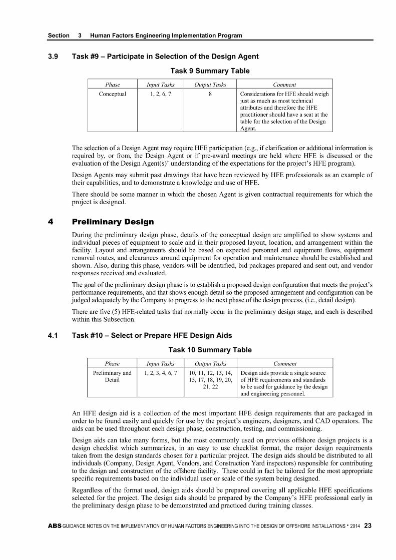
Section 3 Human Factors Engineering Implementation Program
ABS GUIDANCE NOTES ON THE IMPLEMENTATION OF HUMAN FACTORS ENGINEERING INTO THE DESIGN OF OFFSHORE INSTALLATIONS . 2014 23
3.9 Task #9 – Participate in Selection of the Design Agent
Task 9 Summary Table
Phase Input Tasks Output Tasks Comment Conceptual 1, 2, 6, 7 8 Considerations for HFE should weigh
just as much as most technical attributes and therefore the HFE practitioner should have a seat at the table for the selection of the Design Agent.
The selection of a Design Agent may require HFE participation (e.g., if clarification or additional information is required by, or from, the Design Agent or if pre-award meetings are held where HFE is discussed or the evaluation of the Design Agent(s)’ understanding of the expectations for the project’s HFE program).
Design Agents may submit past drawings that have been reviewed by HFE professionals as an example of their capabilities, and to demonstrate a knowledge and use of HFE.
There should be some manner in which the chosen Agent is given contractual requirements for which the project is designed.
4 Preliminary Design During the preliminary design phase, details of the conceptual design are amplified to show systems and individual pieces of equipment to scale and in their proposed layout, location, and arrangement within the facility. Layout and arrangements should be based on expected personnel and equipment flows, equipment removal routes, and clearances around equipment for operation and maintenance should be established and shown. Also, during this phase, vendors will be identified, bid packages prepared and sent out, and vendor responses received and evaluated.
The goal of the preliminary design phase is to establish a proposed design configuration that meets the project’s performance requirements, and that shows enough detail so the proposed arrangement and configuration can be judged adequately by the Company to progress to the next phase of the design process, (i.e., detail design).
There are five (5) HFE-related tasks that normally occur in the preliminary design stage, and each is described within this Subsection.
4.1 Task #10 – Select or Prepare HFE Design Aids
Task 10 Summary Table
Phase Input Tasks Output Tasks Comment Preliminary and
Detail 1, 2, 3, 4, 6, 7 10, 11, 12, 13, 14,
15, 17, 18, 19, 20, 21, 22
Design aids provide a single source of HFE requirements and standards to be used for guidance by the design and engineering personnel.
An HFE design aid is a collection of the most important HFE design requirements that are packaged in order to be found easily and quickly for use by the project’s engineers, designers, and CAD operators. The aids can be used throughout each design phase, construction, testing, and commissioning.
Design aids can take many forms, but the most commonly used on previous offshore design projects is a design checklist which summarizes, in an easy to use checklist format, the major design requirements taken from the design standards chosen for a particular project. The design aids should be distributed to all individuals (Company, Design Agent, Vendors, and Construction Yard inspectors) responsible for contributing to the design and construction of the offshore facility. These could in fact be tailored for the most appropriate specific requirements based on the individual user or scale of the system being designed.
Regardless of the format used, design aids should be prepared covering all applicable HFE specifications selected for the project. The design aids should be prepared by the Company’s HFE professional early in the preliminary design phase to be demonstrated and practiced during training classes.
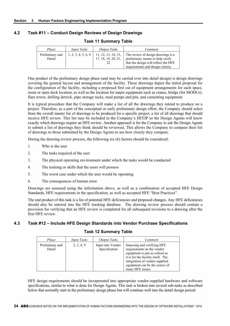
Section 3 Human Factors Engineering Implementation Program
24 ABS GUIDANCE NOTES ON THE IMPLEMENTATION OF HUMAN FACTORS ENGINEERING INTO THE DESIGN OF OFFSHORE INSTALLATIONS . 2014
4.2 Task #11 – Conduct Design Reviews of Design Drawings
Task 11 Summary Table
Phase Input Tasks Output Tasks Comment Preliminary and
Detail 1, 2, 3, 4, 5, 6, 9 11, 12, 13, 14, 15,
17, 18, 19, 20, 21, 22
The review of design drawings is a preliminary means to help verify that the design will reflect the HFE requirements and design criteria.
One product of the preliminary design phase (and may be carried over into detail design) is design drawings covering the general layout and arrangement of the facility. These drawings depict the initial proposal for the configuration of the facility, including a proposed first cut of equipment arrangements for each space, room or open deck location, as well as the location for major equipment such as cranes, bridge (for MODUs), flare tower, drilling derrick, pipe storage racks, mud pumps and pits, and cementing equipment.
It is typical procedure that the Company will make a list of all the drawings they intend to produce on a project. Therefore, as a part of the conceptual or early preliminary design effort, the Company should select from the overall master list of drawings to be produced for a specific project, a list of all drawings that should receive HFE review. This list may be included in the Company’s HFEIP so the Design Agents will know exactly which drawings require an HFE review. Another approach is for the Company to ask the Design Agents to submit a list of drawings they think should be reviewed. This allows the Company to compare their list of drawings to those submitted by the Design Agents to see how closely they compare.
During the drawing review process, the following six (6) factors should be considered:
1. Who is the user
2. The tasks required of the user
3. The physical operating environment under which the tasks would be conducted
4. The training or skills that the users will possess
5. The worst case under which the user would be operating
6. The consequences of human error.
Drawings are assessed using the information above, as well as a combination of accepted HFE Design Standards, HFE requirements in the specification, as well as accepted HFE “Best Practices”.
The end product of this task is a list of potential HFE deficiencies and proposed changes. Any HFE deficiencies should also be entered into the HFE tracking database. The drawing review process should contain a provision for verifying that an HFE review is completed for all subsequent revisions to a drawing after the first HFE review.
4.3 Task #12 – Include HFE Design Standards into Vendor Purchase Specifications
Task 12 Summary Table
Phase Input Tasks Output Tasks Comment Preliminary and
Detail 2, 3, 4, 9 Input into Vendor
Specification Imposing and verifying HFE requirements on the vendor equipment is just as critical as it is for the facility itself. The integration of vendor-supplied equipment can be the source of many HFE issues.
HFE design requirements should be incorporated into appropriate vendor-supplied hardware and software specifications, similar to what is done for Design Agents. This task is broken into several sub-tasks as described below that normally start in the preliminary design phase but will continue well into the detail design period:

Section 3 Human Factors Engineering Implementation Program
ABS GUIDANCE NOTES ON THE IMPLEMENTATION OF HUMAN FACTORS ENGINEERING INTO THE DESIGN OF OFFSHORE INSTALLATIONS . 2014 25
4.3.1 Project Equipment Procurement List From the project equipment procurement list, vendor hardware with HFE design requirements included in their purchase specification should be selected. This list will vary by project but some selection criteria are provided below:
• Equipment involved with safety, crew evacuation, and damage controls, such as lifeboats; firewater pumps; alarm systems; fast rescue boat; fire, smoke and gas detection display panels, and Emergency Shutdown System (ESD)
• Skid mounted equipment, such as chemical injection, pipeline pumps, cooling towers
• Large pieces of equipment, such as mud pumps, shaker tables, heaters, glycol regeneration towers, production separators, cranes
• Equipment that require internal access for maintenance, such as filters and strainers
• Equipment with a history of safety concerns, such as pig launchers and receivers, and cranes
• Control stations, such as the consoles that are placed in the Central Control Room (CCR), ballast control consoles, well control consoles, or any other control panel that possesses controls and displays regardless of its size
• Items provided for movement on and around the platform, such as stairs, ladders, walkways, work platforms, ramps, and manways
• Equipment associated with production, such as gas compressors, power generators, well completion, fuel gas packages, vent flare tips
• Equipment associated with crew habitability, such as the sewage and water treatment plants, and A/C plants, or any other equipment affecting/controlling lighting, temperature, humidity, noise, or vibration
• Any equipment that requires human/equipment interface for operation or maintenance
The equipment list should identify the specific equipment or system, HFE priorities (i.e., low, medium, high) assigned for each item and provide a brief summary of the HFE design issues associated with each item. For a sample equipment list, see Appendix 4, “Example List of Vendor Supplied Equipment Requiring HFE in Purchase Specifications”.
4.3.2 Vendor Purchase Specification HFE design requirements can be extracted from the project specification and inserted into each vendor purchase specification, as required. It is not practical to impose a full HFE specification on every vendor purchase contract, rather, supply only those requirements which are pertinent to a specific piece of equipment or software package. See Appendix 5, “Example HFE Statement to be placed in Vendor Purchase Specifications Packages”.
The use of a standalone HFE specification for skid mounted packages is an effective approach. The challenge is to identify the equipment requiring compliance with HFE specifications. An alternative approach is to insert HFE requirements into the vendor purchase specifications. Identification of the equipment requiring HFE specifications should be made by the Company’s HFE Practitioner with help from operators and maintainers. A tasks analysis can prove quite helpful with this task.
4.3.3 Pre-Bid Meetings There can be meetings held between prospective vendors and the Company or Design Agent to clarify or elaborate on the purchase specification before vendors submit their bid packages. Participation by the HFE Practitioner in those meetings is valuable since many questions deal with the HFE requirements portion of the Request for Bid (RFB), Request for Quotation (RFQ), or Invitation to Tender (ITT) packages. This is especially true if the vendors have not had to respond to HFE requirements before and thus need assistance in identifying exactly what is expected of them.

Section 3 Human Factors Engineering Implementation Program
26 ABS GUIDANCE NOTES ON THE IMPLEMENTATION OF HUMAN FACTORS ENGINEERING INTO THE DESIGN OF OFFSHORE INSTALLATIONS . 2014
4.3.4 Vendor Bid Review As the vendor bid packages are received, each should be reviewed by the HFE Practitioner to determine whether or not the vendor has adequately complied with the HFE requirements in the bid specification. The HFE review should be given to the individual responsible for the final decision on vendor selection, and the HFE review should receive equal consideration to technical comments or review regarding the purchase specifications.
4.3.5 Review Vendor Detail Design Specifications and Drawings When the vendors submit their detail designs, final specifications, and design drawings, they should be reviewed.
4.3.6 Visit Vendors’ Facilities For some vendor-furnished items, it may be worthwhile for the HFE Practitioner to visit the vendor’s facility to inspect the hardware during fabrication. These visits will be primarily to verify that the HFE design inputs are being made to the hardware, and that field run piping or other features have not negated the HFE effort performed by the design team, that equipment labeling is being done in compliance with the HFE standards, and that any other HFE requirements are being met.
4.4 Task #13 – Conduct Special Studies
Task 13 Summary Table
Phase Input Tasks Output Tasks Comment All 3, 4, 9 15, 18, 19, 20, 21,
22, 23 Numerous studies may be conducted by either the owner or the contractor beginning at early stages to help focus on specific HFE issues associated with the performance requirements of the facility, the proposed design, and the human interaction associated.
Special studies may be required, particularly if the project is complex, large, and/or new to the Company. The HFE Practitioner should be involved in all of these studies.
Any HFE involvement, whether as the study leader or just a study participant, should be done by the HFE Practitioner. It should be understood, however, that some studies will require input from operations and engineering personnel, other engineers, or HSE personnel.
Note that special studies can be time-consuming and costly. Any special study should be done only if it will contribute directly to the design effort. The studies identified here may or may not need to be performed for every project. There are several special studies that might be appropriate, but only a limited number are listed here:
4.4.1 Front End Human Factors Engineering Analysis (FEHFEA) The early focus for HFE during a project is on the analysis of Operational and Maintenance (O&M) concerns and lessons learned so that these can be adequately addressed. A Front End Human Factors Engineering Analysis (FEHFEA) or a similar Gross Task Analysis study should be performed under the guidance of HFE Practitioner to address these O&M concerns. The purpose of this task analysis is to identify potential problems in the design of the human-machine interface with regards to the working environment. Studies such as these and operational and functional task analyses should begin shortly after the development of the process flow diagrams (PFD’s). This timing will minimize costs related to design changes and schedule impacts, as well as allow for action items to be addressed effectively during the lifecycle of the project.
The FEHFEA should be executed during the early stages of a project by a multi-disciplinary team with the objective of up-front identification of potential concerns in the design of the facility (plant, control room, workshop, laboratory, office, etc.). This will help result in a more functional design which can reduce the life-cycle costs of the asset.

Section 3 Human Factors Engineering Implementation Program
ABS GUIDANCE NOTES ON THE IMPLEMENTATION OF HUMAN FACTORS ENGINEERING INTO THE DESIGN OF OFFSHORE INSTALLATIONS . 2014 27
On basis of this analysis, design demands are subsequently defined and tested with respect to human factors criteria, taking into account technical, operational, business, and economic requirements. The end product of this task should be a list of specific (wherever possible) HFE design requirements that should be included in the project design specifications.
4.4.2 Function Allocation The purpose of this HFE analysis is to identify which system functions are to be performed by equipment and which tasks are to be performed by personnel. For those tasks allocated to personnel, this analysis determines whether the tasks are compatible with human physiological and psychological capabilities and limitations. The tasks are grouped together and described as a single job or position, which serves as an input for the determination of personnel competency profiles. The HFE Practitioner usually conducts these analyses with support from operations and engineering personnel. However, the data may be collected by other persons for analysis.
4.4.3 Task Analysis A task analysis consists of identifying and listing each task in sequence that should be performed by the operator or maintainer to complete a specific job. Important information can be added for each identified task, such as the time required to perform each task, the criticality of the task, the accuracy required for each task, and who will do the tasks (if the job is a multi-person job).
Two levels of Task Analysis exist, Gross and Fine. The Gross Analysis uses only the top level task listing and usually covers a wider range of tasks than does the Fine Analysis. A Fine Task Analysis usually covers a small and finite piece of a Gross Task Analysis, and includes a very detailed description of all the steps required to complete a specific task or function. A running timeline is kept for each task so task completion times can be developed.
4.4.4 Hazard and Operability Studies (HAZOPs) HAZOPs are one of the more common process hazard analysis techniques used in the offshore industry. HAZOPs are conducted by a team composed of individuals representing the engineering and technical disciplines, HSE, operations, and HFE. A HAZOP is performed after a system has reached the level of design that will allow the Team to look at the proposed design and identify where each equipment or system failure or system upset could occur. Additionally, the possible cause(s) of the failures or upsets (including human error) and the hazard level associated with each failure or upset is assessed, resulting in recommended changes in design, training, procedures, etc., that could prevent the hazard from occurring, or alleviate the hazard if it actually happened.
Without HFE representation, the HAZOP team may misapply increased training or extended procedural changes as the solution to a particular identified hazard when the best solution would be an equipment design change.
The HFE Practitioner should prepare for HAZOP participation by reviewing relevant documentation related to the design under review, such as layout drawings, and piping and instrumentation diagrams/drawings (P&IDs). The HFE Practitioner, working with Operations and Maintenance personnel, can define the tasks that an operator would be expected to perform and identify those tasks that would be likely to produce human error in its operation or maintenance.
4.4.5 Valve Criticality Analysis (VCA) One of the more frequent human-machine interactions on an offshore facility is the operation and/or maintenance of valves. The purpose of this study is to classify and then locate valves based on their criticality. The classification is based on a formal set of criteria agreed upon by all members (disciplines) of the engineering, design, operations, and maintenance teams.
The main objectives and benefits of the study are:
1. To formalize the decision process for determining the location of all valves in the facility.
2. To provide designers with a clear guidance on valve locations and orientations.
3. To enhance the design review process to alleviate lengthy discussions on valve orientation as the design progresses to completion.
4. To verify that operational and maintenance requirements are addressed when deciding on the location of a valve.

Section 3 Human Factors Engineering Implementation Program
28 ABS GUIDANCE NOTES ON THE IMPLEMENTATION OF HUMAN FACTORS ENGINEERING INTO THE DESIGN OF OFFSHORE INSTALLATIONS . 2014
This process has been shown to reduce the cost of over-design (i.e., unnecessary length of piping in order to make valves readily accessible from deck level or the provision of permanent stairway access and work platforms for access to non-critical and non-operating valves).
The study involves the evaluation of the location and orientation of all major valves. The latest revisions of P&ID’s are used to identify and compile a list/table of all types of valves to be utilized on the facility/installation. The list of valves is to be reviewed by the team and the team will brainstorm to agree upon the accessibility and classification criteria designated for each type of valve. The classification criteria will help promote the adequacy of the design to perform operations and maintenance tasks safely and efficiently during normal and upset conditions.
The success of the VCA will greatly depend on the familiarity of the team members with their roles and active contributions during the sessions. To prepare team members for participation in the study, participants should have a familiarization with the following documents as well as HFE specification:
1. Project Design Basis
2. PFDs and PIDs
3. Equipment Arrangement/Layout drawings
It will be the responsibility of engineering management and all relevant disciplines to demonstrate how the classification is implemented and complied with during the various phases of the design process. It is recommended that the P&IDs be updated to show or highlight all valve categories. For more information, refer to the ABS Guidance Notes on the Application of Ergonomics to Marine Systems or the ABS Guide for Ergonomic Notations.
4.4.6 Maintenance/Operational Access Criticality Analysis An analysis of maintenance tasks should be performed for the purpose of sizing and outfitting maintenance workspaces. The analysis addresses concerns such as: design of maintenance platforms; work surfaces; work envelopes; tools, spare parts and spent part stowage; and consumables storage at a maintenance site during planned or corrective maintenance.
The analysis is also intended to identify requirements for lifting and carrying devices for heavy or awkward loads; and to facilitate maintenance action work flow.
For more information, refer to the ABS Guidance Notes on the Application of Ergonomics to Marine Systems or the ABS Guide for Ergonomic Notations.
4.4.7 Emergency Egress, Escape, and Evacuation The purpose of this study is to review any HFE requirements during an emergency. This may include an analysis of the escape routes, muster stations, and the integrity of the temporary refuge, the survival craft/lifeboats and fast rescue craft.
During an emergency, the most critical aspects of operations are the communications to personnel of the hazardous event and the design provisions that have been included to promote integrity and visibility of the egress routes. This includes HFE inputs on the frequency, type, and magnitude of the tones utilized for the alarms; the color, frequency/intensity, and location of alarm lights; the markings, lighting, protection/shielding (plating, grating or heat shields), and clear width of escape routes (especially for stretcher access).
After the egress routes, the next most critical location is the Muster Stations. There are normally two stations, one on each side of the installation, and one is almost always at the living quarters (on large facilities).
The Muster Station is a designated point for verifying that all personnel are accounted for before the final decision to abandon the facility is made. The most significant HFE aspects of this location include access/egress for the normal compliment of personnel on the installation, the size of the Muster Station (adequate enough in size to minimize claustrophobic fears or stress with full evacuation equipment on), communications in the refuge area (clarity), heat/carbon dioxide accumulation, stress, physical protection against the hazardous event, and proximity to survival craft/lifeboats.
Generally, a secondary or alternative muster point is designated, and this location requires the same HFE attention as the primary muster area.

Section 3 Human Factors Engineering Implementation Program
ABS GUIDANCE NOTES ON THE IMPLEMENTATION OF HUMAN FACTORS ENGINEERING INTO THE DESIGN OF OFFSHORE INSTALLATIONS . 2014 29
The final safety-critical system is the survival craft (lifeboats) and their boarding/staging locations. Survival craft should receive HFE attention during design, testing, maintenance, and operations. This would include verifying cultural calibration of the seats/entrance and critical pieces of operating equipment in the boat, stretcher access, recovery of overboard personnel, and operations and control of the lifeboat. The HSE Specialist normally performs the study with input from the HFE Practitioner.
4.4.8 Material Handling Study The purpose of this study is to define the requirements for material handling, either mechanically assisted or performed manually. This study is normally conducted by engineering with inputs from the HFE Practitioner.
Only those items that exceed permissible manual lifting and/or carrying limits defined in the project’s HFE design standards should be included in this study. This study is conducted to:
• Prevent crew injuries from manual materials handling activities
• Prevent or reduce material damage to the item being moved and the facility
• Provide prearranged bolted or welded access removal plates in the facility structure
• Assist in the selection and acquisition of material handling equipment
• Provide facility design inputs (e.g., aisle or walkway widths to allow passage and turning of hand and push-carts
• Reduce downtime during maintenance or operation due to unplanned obstacles that would have been eliminated if such a study had been conducted
The end product of this study is a list of all equipment, stores, spare parts, etc., that should be moved on, off, or around the offshore facility, and the assisted lifting device(s) that should be used to lift or move each item. The list should also contain:
• The name of the item to be lifted (including dimensions and weight)
• The type of assisted lifting and/or moving device that will be provided (e.g., padeye, beam clamp, come-along; jib, boom, overhead or portable A-frame crane; monorail; pallet jack, etc.).
• Equipment breakdown joints if equipment should be disassembled for lifting and/or movement
• Item removal routes (shown on a schematic drawing) to move the item on, off, or around the facility
4.4.9 Crane Operations Study Crane studies may include the review of the operator interface controls, workplace habitability evaluations, accessibility issues for maintenance access including ladders and handrails, and review of operational procedures and facility labeling.
The purpose of this study is five-fold:
• Optimize the location and size of drop zones or laydown areas, particularly for the supply cranes.
• Identify, eliminate, or reduce the number and criticality of “blind” lifts.
• Identify the sites of major maintenance or repairs on the crane (e.g., crane machinery room), boom tip sheaves, removal and replacement of slew drives or winch drum brakes, removal and replacement of main and auxiliary lifting wires, and replacement of boom mounted lights (if there are any), and make sure that access to and from the work sites, as well as the sites themselves, allows these tasks to be performed safely and easily.
• Approve crane operator viewing angles from the crane cab to promote an unobstructed operator viewing area of supply boats during replenishment of the facility.
• Verify that all operator controls and displays are in compliance with the project’s controls and displays design standards (e.g., the ABS Guidance Notes on the Application of Ergonomics to Marine Systems or ASTM F 1166).

Section 3 Human Factors Engineering Implementation Program
30 ABS GUIDANCE NOTES ON THE IMPLEMENTATION OF HUMAN FACTORS ENGINEERING INTO THE DESIGN OF OFFSHORE INSTALLATIONS . 2014
This study is conducted by engineering with input from the HFE Practitioner on issues such as operator eye positions based on the appropriate anthropometric dimensions for the expected user populations, as well as other relevant information on human visual and reach capabilities and limitations.
4.4.10 Control Room Study The purpose of this study is to focus not only on the control room layout and ambient environment, but also on the activities to be performed under both normal and abnormal (emergency) conditions. The aim is to further identify any factors that may negatively affect the operator to detect deviations, diagnose the situation, and take action following a given abnormal situation in the process and the subsequent sequence of events. The weak points identified by the study are then used as a basis for design change recommendations.
The Control Room Study group/team should consist of a control room operator, instrument engineer, process engineer and HFE Practitioner. Additional personnel from specialized disciplines such as electrical, HVAC, HSE, and Human Resources may be required to participate for short periods during special topics of the study.
The final product of this study should be a proposed arrangement and layout of the Control Room. Depending on when this study is completed, the layout and arrangement drawing may be only relational (i.e., not to scale, which will be added later). If sufficient knowledge exists, the layout and arrangement could be to scale and of sufficient detail to be of detail design quality.
4.4.11 Quantitative Risk Assessment Study On limited, but critical operational scenarios (e.g., supply boat approach and tie-up, drilling, or production riser handling), quantitative risk assessment studies should be performed. These studies help to identify likely opportunities for an accident or incident, identify the causes of those situations, attempt to determine the probability of such a situation happening, and then determine how that probability changes if alterations are made in facility design and/or human participation in the operation.
In these studies, probabilities are assigned to equipment failures and human errors occurring. Changes based on potential impact are made in equipment design or procedures to reduce the probabilities of error, and the whole operation reliability is recalculated to see if safety and efficiency was improved.
The final product of this effort is a report identifying the equipment and human errors identified as potential causes or contributors to an accident or incident. Proposed changes in hardware design and/or human involvement should be listed along with the estimated changes in the increased probability of overall mission success associated with the changes, due to the quantitative nature of the study.
The limited experience with these studies shows them to be labor-intensive (due to the number of personnel required to participate), and the need for persons with very special skills to determine the probabilities. However, the results can be effective in pointing the way to major design decisions affecting an offshore facility.
Identifying applicable studies and determining when they should be performed should be the responsibility of the HFE Practitioner in consultation with management, operations, and engineering personnel.
5 Detail Design The goal of the detail design phase is to have defined both in functional and physical terms the detailed requirements for implementation/construction.
During the detail design phase, design drawings are created that, when approved, will establish baseline equipment configurations. Making changes and enhancements to the design in this phase can be quite difficult (and expensive). The outputs of this stage are used to guide fabrication of preproduction prototypes for development tests.
There are five (5) HFE-related tasks that normally occur in the detail design stage, and each is described within this Subsection.

Section 3 Human Factors Engineering Implementation Program
ABS GUIDANCE NOTES ON THE IMPLEMENTATION OF HUMAN FACTORS ENGINEERING INTO THE DESIGN OF OFFSHORE INSTALLATIONS . 2014 31
5.1 Task #14 – Provide General HFE Design Inputs
Task 14 Summary Table
Phase Input Tasks Output Tasks Comment All 1, 2, 3, 4 6, 13, 14, 15, 18,
19, 20, 21, 22, 23 This provision of “HFE Design” is the basis of most input to the design and engineering teams. It is the application of HFE standards and “best practices” in a proactive manner.
One significant, but difficult to quantify, task performed by the HFE Practitioner during detail design is the provision of general HFE design assistance to the engineers and designers.
Design issues that arise may consist of a new application of a design, a scenario that is not represented by criteria in the HFE standard or a configuration that requires user input for the engineer to provide the best solution. The HFE Practitioner can most easily provide this type of input if they are co-located where the design work is being done. It is not necessary that the HFE Practitioner remain physically in the design area at all times, but the design team members should be aware that the HFE Practitioner is available to provide assistance.
The reasons that these design inputs should come from an HFE Practitioner are:
1. They may result from HFE analyses and studies.
2. There are no direct criteria available from the design standards.
3. The HFE design standards require interpretation to fit the specific design issue in question.
4. The designers are often uncertain how to interpret the HFE requirements and need assistance. Assistance is especially required where there is a conflict between different HFE requirements, or between HFE and other engineering requirements.
As with the other HFE tasks, all recommended HFE design inputs should be recorded in the HFE tracking database.
5.2 Task #15 – Conduct Facility Labeling Program
Task 15 Summary Table
Phase Input Tasks Output Tasks Comment Detail and CFIC 3, 4, 6, 9, 12 21, 22 Labeling programs provide consistent
and comprehensive labeling designs and applications throughout a facility with significant benefits in safety and operational performance.
From an enhanced personnel safety and operability perspective, a well-labeled facility is a major HFE contribution. A full facility-wide labeling program can be labor-intensive and time-consuming. However, it has been proven to be quite cost-effective.
Facility-wide labeling includes the following types of labels:
• Identification labels that identify individual equipment, compartments, and spaces
• Control and display labels that are provided to identify the control or display, or to show how to actuate or manipulate a control
• Pipe markers (which include pipe content and direction of flow arrows) all presented in a color code to help the operator/maintainer identify what is in the pipe
• Hazard identification and warning signs

Section 3 Human Factors Engineering Implementation Program
32 ABS GUIDANCE NOTES ON THE IMPLEMENTATION OF HUMAN FACTORS ENGINEERING INTO THE DESIGN OF OFFSHORE INSTALLATIONS . 2014
• Instruction labels that provide either step-by-step instructions or general information on how to perform a specific task (e.g., launch a lifeboat)
• Information labels that provide general information
• Graphic labels, such as a piping diagram, equipment schematic or chart
Detailed specifications for the design, construction, and installation of all of the above labels should be included in the HFE specifications.
Typically, labels come from two different sources:
1. Those written and manufactured by the Company, Design Agent, or Construction Yard and installed by the Yard
2. Those written, manufactured, and installed by the Vendors.
Therefore, the two different sources should be familiar with, and consistently use, the same label design specification.
The labeling effort should begin early in the detail design phase, as soon as the first P&IDs are released. The P&IDs will be a principal source of where, and of what type, labels will be produced. The labeling requirements should be part of the project’s design specification.
5.3 Task #16 – Prepare or Review Operations and Maintenance Manuals
Task 16 Summary Table
Phase Input Tasks Output Tasks Comment Detail and CFIC 1, 2, 3, 6, 9, 12. 22, 23 From an HFE perspective, the design
of manuals should promote concise and visually clear information to the user to facilitate procedures.
Operation and maintenance manuals come from three basic sources:
• Manufacturers of equipment purchased directly (e.g., fans, galley equipment, sanitary facilities, motors and pumps, etc.)
• Vendors who produce equipment skids or packages that contain manufactured equipment along with their own design of piping and instrumentation
• Those prepared by the Company, Design Agent, or Construction Yard based on their own designs
Research conducted about how people read and process information from books, manuals, checklists, etc., has been translated into definitive design requirements that, if followed in the content, layout, format, location, and use of text and visual aids, can enhance the usability, effectiveness, and readability of a manual provided for operators or maintainers.
Therefore, the HFE Practitioner should provide HFE design guidelines for the preparation of manuals and review the manuals to promote compliance with the HFE guidelines. Examples of special case operations procedures and manuals written by HFE Practitioner include:
• Procedures for Contacting Approaching Vessels Detected on the Obstacle Avoidance Radar
• Abandon Platform Procedures
• Pig Launching Procedures
• Meter Proofing Operations Procedures
The writing task should start in the detail design phase as soon as the first completed equipment; skids, or packages are delivered to the Construction Yard. The end product of this task will be the operating procedure or manual provided to the crew. For additional guidance on procedure and technical manual writing refer to the ABS Guidance Notes on the Development of Procedures and Technical Manuals.

Section 3 Human Factors Engineering Implementation Program
ABS GUIDANCE NOTES ON THE IMPLEMENTATION OF HUMAN FACTORS ENGINEERING INTO THE DESIGN OF OFFSHORE INSTALLATIONS . 2014 33
5.4 Task #17 – Conduct Computer Aided Design (CAD) Reviews
Task 17 Summary Table
Phase Input Tasks Output Tasks Comment Preliminary,
Detail, and CFIC 1, 2, 3, 4, 5, 6,
9, 10, 11, 12, 13 6, 18, 19, 20, 21,
22, 23 Utilizing CAD models to conduct design reviews and verification of HFE requirements allows changes to be made early in design, and the capability to “see” an environment from the user perspective may uncover usability or access issues otherwise unknown without the use of the tool.
From an HFE perspective, the most significant change in the design process over the last two decades has been the increase in the creation and display of facility design via a three-dimensional CAD model.
There are several CAD models that offer the ability to “see” the design in photographic-like quality images. The models show all the components (e.g., stairs, ladders, piping, equipment components, lighting, structural steel, wireways, valves, lockers, cabinets, fire fighting equipment, etc.) in realistic shape, size, and detail. Accurate dimensions of component size and clearances can be also derived from the model.
CAD models provide value to the HFE program in two ways. First, they offer the opportunity to review and evaluate designs as they are first being proposed or created by the engineers, designers, or CAD operators. These early reviews are usually conducted on a single piece of equipment or very limited portion of the overall facility. They are done at the individual CAD operator stations, and done frequently as the design progresses.
The second way of using CAD for review is during the formal CAD design reviews, usually done at the 30%, 60%, and 90% design completion milestones. At the 30% model review, the HFE goal is to verify that there will be sufficient clearances and unobstructed paths for movement of people and equipment, as well as accessibility to individual pieces of equipment and valves for operation and maintenance. Stairs, ladders, ramps, and other access aids will be checked. General placement, orientation, and arrangement of equipment will also be evaluated, as will the arrangement of the pathways and egresses for Emergency Escape Routes (EER). Lack of detail in the design will limit the scope of the 30% evaluation of the control station design or other details, but these will be reviewed at later review completion milestones. The reviews will compare the proposed design against the project specific HFE design standards.
In the 60% model review, the HFE goal will be to verify that sufficient and proper access at elevations for operations and maintenance is provided, as well as valve access for operation and maintenance. Further clarification of EER routes, materials handling reviews, evaluation of personal safety systems, and a first look at operator workstation design, orientation, and layouts will be completed. Design detail will be sufficient enough to allow maintenance activities to be evaluated
The 90% model review will allow for verification of the previous recommendations and a complete review of all HFE design standards. Other HFE details that are finalized at this time are related to the expected personnel population’s anthropometrics, line of sight requirements, workflow/traffic patterns, and operational/ maintenance envelopes. These issues are vital for properly designed human-machine interfaces.
In these reviews, many individuals (e.g., operators, engineers, maintenance personnel, HSE representatives, HFE professional(s), vendor representatives, program managers, and the CAD operator) are all gathered in one room, usually outfitted to show the CAD model on a large screen). The review is conducted by having each room, space, open deck area, piece of equipment, piping, wireways, stairs, control consoles and panels, valves, walkways, and all other components comprising a defined area looked at and evaluated by all parties in the room.
From an HFE perspective, the proposed design is primarily compared against the HFE design standards used for the project. On occasion, the design is not in conflict with the contractually-binding HFE design standard but just may be in contradiction with normally good HFE design practices. Every HFE design deficiency identified during this CAD review should be entered into the HFE tracking database.

Section 3 Human Factors Engineering Implementation Program
34 ABS GUIDANCE NOTES ON THE IMPLEMENTATION OF HUMAN FACTORS ENGINEERING INTO THE DESIGN OF OFFSHORE INSTALLATIONS . 2014
6 Construction, Fabrication, Installation, and Commissioning (CFIC)
6.1 Task #18 – Conduct Periodic Visits to the Construction Yard and Vendor Fabrication Sites
Task 18 Summary Table
Phase Input Tasks Output Tasks Comment CFIC 3, 5, 6, 9 22 Visits to the construction yard by the
HFE Practitioners will provide an opportunity to identify potential HFE issues that may arise independent of drawing and plans, but rather due to design decisions made at the yard.
In many cases, HFE compliance by fabricators and construction staff is accomplished by adhering to the project drawings. However, for some details that are not included on the drawings (such as the position of valve control handles), the HFE Practitioner should check that the installation meets HFE specifications and design standards. Other areas that are checked in the yard include the installation of signs, labels, pipe markers, and field mounted instructions.
A particularly important activity during these visits is to verify that installation of “field run” or “field installed” piping, wiring, equipment, etc., does not negate HFE design inputs made during detail design or create new hazards that did not previously exist.
This activity is usually performed by the Company’s HFE Practitioner to verify that the construction yard is fulfilling the HFE requirements. The visits normally involve a simple “walkthrough” by the HFE Practitioner who visually inspects the fabrication or construction work completed to date to detect any HFE problems created as a result of the fabrication or construction activity.
The number and frequency of inspection tours will vary but should increase as the construction progress increases. Depending on the size of the project, visits can range from one or two to as often as once or twice a week.
Any detected HFE issues should be entered into the HFE tracking database and should be brought to the attention of the Company, Vendor, or Construction Yard inspectors.
6.2 Task #19 – Monitor Selected Engineering Tests to Identify HFE Design Deficiencies
Task 19 Summary Table
Phase Input Tasks Output Tasks Comment CFIC 3, 4, 9 6, 20, 22, 23 Testing of systems following
construction phases can identify previously unknown HFE issues including both physical hazards as well as issues with the tasks required as a result of the design, such as access for maintenance or operation.
Conducting a formal HFE-specific testing program during or after the facility design and construction phases is normally not done. Instead, the monitoring of tests conducted by engineering on a limited and selected number of individual pieces of equipment may be performed. These may include key systems such as the ballast system, riser tensioners, power turbines, and cranes. In these tests, the HFE role is to monitor the tests to determine if any HFE design deficiencies or oversights can be detected.
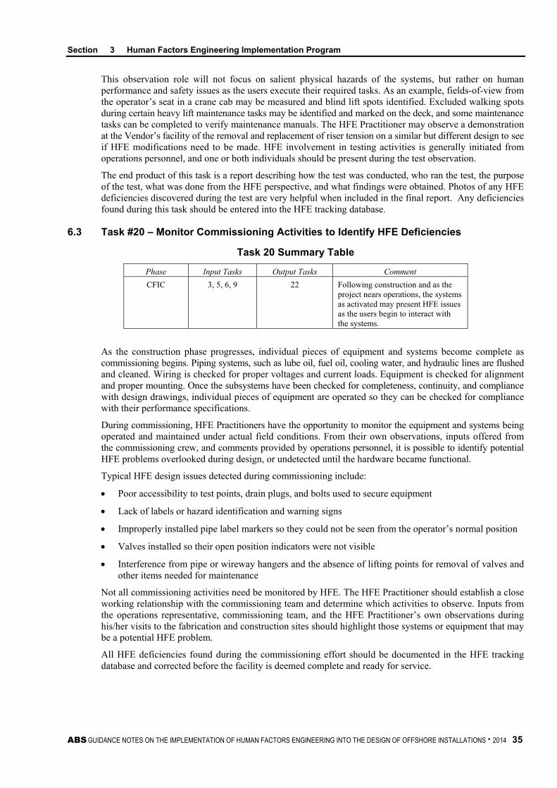
Section 3 Human Factors Engineering Implementation Program
ABS GUIDANCE NOTES ON THE IMPLEMENTATION OF HUMAN FACTORS ENGINEERING INTO THE DESIGN OF OFFSHORE INSTALLATIONS . 2014 35
This observation role will not focus on salient physical hazards of the systems, but rather on human performance and safety issues as the users execute their required tasks. As an example, fields-of-view from the operator’s seat in a crane cab may be measured and blind lift spots identified. Excluded walking spots during certain heavy lift maintenance tasks may be identified and marked on the deck, and some maintenance tasks can be completed to verify maintenance manuals. The HFE Practitioner may observe a demonstration at the Vendor’s facility of the removal and replacement of riser tension on a similar but different design to see if HFE modifications need to be made. HFE involvement in testing activities is generally initiated from operations personnel, and one or both individuals should be present during the test observation.
The end product of this task is a report describing how the test was conducted, who ran the test, the purpose of the test, what was done from the HFE perspective, and what findings were obtained. Photos of any HFE deficiencies discovered during the test are very helpful when included in the final report. Any deficiencies found during this task should be entered into the HFE tracking database.
6.3 Task #20 – Monitor Commissioning Activities to Identify HFE Deficiencies
Task 20 Summary Table
Phase Input Tasks Output Tasks Comment CFIC 3, 5, 6, 9 22 Following construction and as the
project nears operations, the systems as activated may present HFE issues as the users begin to interact with the systems.
As the construction phase progresses, individual pieces of equipment and systems become complete as commissioning begins. Piping systems, such as lube oil, fuel oil, cooling water, and hydraulic lines are flushed and cleaned. Wiring is checked for proper voltages and current loads. Equipment is checked for alignment and proper mounting. Once the subsystems have been checked for completeness, continuity, and compliance with design drawings, individual pieces of equipment are operated so they can be checked for compliance with their performance specifications.
During commissioning, HFE Practitioners have the opportunity to monitor the equipment and systems being operated and maintained under actual field conditions. From their own observations, inputs offered from the commissioning crew, and comments provided by operations personnel, it is possible to identify potential HFE problems overlooked during design, or undetected until the hardware became functional.
Typical HFE design issues detected during commissioning include:
• Poor accessibility to test points, drain plugs, and bolts used to secure equipment
• Lack of labels or hazard identification and warning signs
• Improperly installed pipe label markers so they could not be seen from the operator’s normal position
• Valves installed so their open position indicators were not visible
• Interference from pipe or wireway hangers and the absence of lifting points for removal of valves and other items needed for maintenance
Not all commissioning activities need be monitored by HFE. The HFE Practitioner should establish a close working relationship with the commissioning team and determine which activities to observe. Inputs from the operations representative, commissioning team, and the HFE Practitioner’s own observations during his/her visits to the fabrication and construction sites should highlight those systems or equipment that may be a potential HFE problem.
All HFE deficiencies found during the commissioning effort should be documented in the HFE tracking database and corrected before the facility is deemed complete and ready for service.

Section 3 Human Factors Engineering Implementation Program
36 ABS GUIDANCE NOTES ON THE IMPLEMENTATION OF HUMAN FACTORS ENGINEERING INTO THE DESIGN OF OFFSHORE INSTALLATIONS . 2014
6.4 Task #21 – Observe Facility Installation Activities to Identify HFE Design Deficiencies
Task 21 Summary Table
Phase Input Tasks Output Tasks Comment CFIC 23 6, 22 As the final stage in installation, a
review of the tasks required may uncover additional previously-latent HFE issues.
For those design projects that require the facility to be moved from its construction or fabrication site to a permanent installation location, such as an offshore rig or platform, there are tasks that are performed associated with the actual installation of the facility at its permanent working location. Some of these tasks may be associated with “anchoring” the facility in place. Other tasks involve making final connections to equipment on the facility and filling tanks (e.g., oil, water, and hydraulic reservoirs).
As with observing the commissioning activities, observing the installation process can be of value to the HFE Practitioner as a means of identifying potential HFE design deficiencies not detectable in any way other than when installation is completed. Also like commissioning, the sources for identifying HFE problems will come from those persons doing the installation and the HFE Practitioner’s observations.
Of all the tasks performed after construction, this task tends to yield the least number of HFE deficiencies, especially ones that can be corrected at this point in the design process. Nevertheless, for a company desiring to offer HFE every opportunity to contribute to the personnel safety and efficiency, this task should be included in the project to provide lessons learned for future designs.
7 Operations When the facility is in operation, generally some form of feedback is required. The importance of the information gathered during operations cannot be understated. This information is invaluable to the designers, engineers and HFE Personnel as feedback on the process and outcome of their efforts and provides a loop of continuous feedback as these personnel move from project to project.
7.1 Task #22 – Follow-up Evaluation after Period of Operation
Task 22 Summary Table
Phase Input Tasks Output Tasks Comment Operations 3, 4, 9 23 The assessment of the project after
operational provides insight into actual human performance and usability of the systems that should be collected and fed back to the sustainment of the project as well as into the development of new projects.
One task that is not regularly included is a follow-up review of the design after a period of on-site operation. The purpose of a follow-up review is to obtain feedback, via written and personal interviews, regarding HFE successes and failures relative to operability and maintainability of the facility.
Based on past projects where follow-up operability and maintainability reviews have been completed, the follow-up review tasks listed below are recommended for future offshore design projects:
• Conduct operability assessments at one year and three years. If only one review is conducted, use the three-year period.
• Obtain operator feedback via written and personal interviews regarding HFE successes and failures relative to operability and maintainability, emphasizing feedback for specific design features or equipment where HFE was included.

Section 3 Human Factors Engineering Implementation Program
ABS GUIDANCE NOTES ON THE IMPLEMENTATION OF HUMAN FACTORS ENGINEERING INTO THE DESIGN OF OFFSHORE INSTALLATIONS . 2014 37
• Obtain accident/incident data from the facility for the identification of continued HFE design deficiencies, or support for a particular design input.
• Develop a lessons-learned file or database and make sure this information is disseminated to other new projects being planned.
• Review modifications made by the crew on this facility to correct HFE problems detected during the operations period and inspect modifications or upgrades made to the facility since its installation to determine if HFE problems exist in the changes made to the facility after its original design.
The information gathered during operations is invaluable to the designers, engineers and HFE personnel as feedback on the process and outcome of their efforts. It provides a loop of continuous feedback as personnel move from project to project.
8 General Task HFE efforts should be reported to senior project management throughout the project lifecycle. The report should describe HFE issues/concerns which were incorporated as well as those that were not.
A report should be prepared at the end of each design phase and revised/updated with any additional HFE work from the construction and operational phases of the project. This database should be made available to any follow-on design project.
8.1 Task #23 – Prepare Progress Reports
Task 23 Summary Table
Phase Input Tasks Output Tasks Comment All All ----- Strictly as a means of communication,
the progress report helps verify that challenges are being addressed and activities are proceeding according to schedule.
Typically, the HFE progress report is prepared monthly and is submitted to the Project Manager and HFE Champion. The report briefly describes the HFE activities completed during the past month, general status of the HFE program, deliverables made, number and location of visits made to the Construction Yard and/or Vendors, any challenges identified, and planned activities for the coming month. Since the interaction between the HFE Practitioner and the Program Manager and HFE Champion should be on a regular and routine basis throughout the month, it should not be necessary to prepare a detailed and lengthy report. Instead, the report should only summarize the HFE activities.
38 ABS GUIDANCE NOTES ON THE IMPLEMENTATION OF HUMAN FACTORS ENGINEERING INTO THE DESIGN OF OFFSHORE INSTALLATIONS . 2014
A p p e n d i x 1 : R e f e r e n c e s
A P P E N D I X 1 References
1. American Bureau of Shipping. Guide for Ergonomic Notations. Houston, TX.
2. American Bureau of Shipping. Guide for Crew Habitability on MODUs. Houston, TX.
3. American Bureau of Shipping. Guide for Crew Habitability on Offshore Installations. Houston, TX.
4. American Bureau of Shipping. Guidance Notes on the Application of Ergonomics to Marine Systems. Houston, TX.
5. American Society for Testing and Materials. (2013). Standard Practice for Human Engineering Design for Marine Systems, Equipment and Facilities (ASTM F 1166 – 2013). West Conshohocken, PA.
6. Harbour, W. Dave, Kracik, J., and Ford, David.,An Ergonomic Process Oriented Approach to Driller’s Consoles. (IADC/SPE 39330), Proceedings of 1998 IADC/SPE Drilling Conference, Dallas, TX, March 3-4, 1998.
7. Hendriske, E.J., Atkinson, P., Miller, G., McSweeney, K.P., Connor, G., Poblete, B., Meyer, R., O’Connor, P and Heber, H., Effectively Including Human Factors in the Design of New Facilities. Proceedings of the 2nd International Workshop on Human Factors in Offshore Operations. Houston, TX, April 8-10, 2002.
8. International Ergonomics Association (IEA). http://www.iea.cc/
9. McCafferty, D., McSweeney, K., Mawby, M., Connor, G., and DeKoker, T. Human Factors Engineering Implementation Strategy: A Generic Approach. (OTC 14294). Proceedings of 2002 Offshore Technology Conference, Houston, TX. May 6-9, 2002.
10. McCafferty, Denise B., E.Johan Hendriske and Gerry E Miller. Human Factors Engineering (HFE) and Cultural Calibration for Vessel and Offshore Installation Design. In Michael Kaplan (Ed.) Cultural Ergonomics, ELSEVIER, Oxford, UK, 2004.
11. Miller, G. Human Factors Engineering (HFE): What is it and how can it be used to Reduce Human Errors in the Offshore Industry. (OTC 10876). Proceedings of 1999 Offshore Technology Conference, Houston, TX, May 3-6, 1999.
12. Robinson, N.L. Starting Right: Sable Offshore Energy Project’s HFE Program. (OTC 10877). Proceedings of Offshore Technology Conference, Houston, TX May 3-6, 1999.
13. Sworn, A and Stirling, J. Opportunities for Increased Safety and Operability of a Deepwater Semi-Submersible Through the Application of HFE, (OTC 10882), Proceedings of 1999 Offshore Technology Conference, Houston, TX, May 3-6, 1999.
14. Woodson, Wesley E., Human Factors Design Handbook, McGraw-Hill Book Company, New York, NY, 1981.
15. Wulff, I.A., Westgaard, R.H., and Rasmussen, B., Ergonomics Criteria in Large- Scale Engineering Design I. Management by Document Only? Formal Organization vs. Designers Perceptions, Applied Ergonomics, Vol 30(3). p191-205. Elsevier 1999.
16. Wulff, I.A., Westgaard, R.H., and Rasmussen, B., Ergonomics Criteria in Large- Scale Engineering Design II. Evaluating and Applying Requirements in the Real World of Design, Applied Ergonomics, Vol 30(3). P207-221. Elsevier 1999.
ABS GUIDANCE NOTES ON THE IMPLEMENTATION OF HUMAN FACTORS ENGINEERING INTO THE DESIGN OF OFFSHORE INSTALLATIONS . 2014 39
A p p e n d i x 2 : A c r o n y m s a n d A b b r e v i a t i o n s
A P P E N D I X 2 Acronyms and Abbreviations
ABS American Bureau of Shipping
ASTM American Society of Testing and Materials
BOD Basis of Design
CAD Computer Aided Design
CCR Central Control Room
CD Conceptual Design
CFIC Construction/Fabrication/Installation/Commissioning
CHFP Certified Human Factors Professional
CPE Certified Professional Ergonomist
DD Detail Design
EER Emergency Escape Routes
ESD Emergency Shutdown System
FEHFEA Front End Human Factors Engineering Analysis
HAZOP Hazard and Operability Studies
HFE Human Factors Engineering
HFEIP Human Factors Engineering Implementation Plan
HFEPP Human Factors Engineering Program Plan
HSE Health, Safety and Environment
HVAC Heating, Ventilation, and Air Conditioning
IMO International Maritime Organization
ISO International Organization for Standardization
M Erg S Member of the Ergonomics Professional Register
NORSOK Norwegian Oil Industry Association and the Federation of Norwegian Engineering Industries
O&M Operational and Maintenance
PD Preliminary Design
PFD Process Flow Diagram
RFB Request for Bids
RFP Request for Proposal
SOW Statement of Work
UK HSE United Kingdom Health Safety Executive
USCG United States Coast Guard
VCA Valve Criticality Analysis

40 ABS GUIDANCE NOTES ON THE IMPLEMENTATION OF HUMAN FACTORS ENGINEERING INTO THE DESIGN OF OFFSHORE INSTALLATIONS . 2014
A p p e n d i x 3 : E x a m p l e H F E I P
A P P E N D I X 3 Example HFEIP
*Note: This example HFEIP may differ slightly from the tasks presented in these Guidance Notes. The tasks in these Guidance Notes are intended to be tailored to each project.
1 Human Factors Implementation Plan Overview This Human Factors Engineering Implementation Plan (HFEIP) identifies and describes human factors engineering (HFE) activities for the XXXX Project. The HFEIP covers the entire Project time period, including detail design, construction and installation and commissioning, and operations phases of the Project.
The HFE activities outlined in this HFEIP are based on XXXX offshore and ship HFE design and project experience. The HFEIP also includes HFE activities based on our assessment of the XXXX Project’s written materials including the Design Basis, various Design Philosophies, specifications, and Statement of Work (SOW) documents.
2 Background Prior to the preparation of the HFEIP, XXXX reviewed the Design Basis documentation. The objective of this exercise was to identify areas where the Design Basis references HFE as a type of required design input or where the language in the documents implied that HFE analysis should occur. Such statements are referred to in this report as “HFE call-outs”. After this exercise, based on experience with similar projects, XXXX determined other HFE activities that were not mentioned in the project documentation, but that would normally be conducted during a project to give full and sufficient attention to human factors issues.
Based on the review process, XXXX identified the following general HFE and safety philosophies. The philosophies served as guidance as to the Company’s intentions with regard to human factors engineering on the project. These philosophies are documented below.
1. Providing a workplace that is as safe and easily maintained as reasonably practicable for a wide range of expected user populations
2. Provision of sufficient access around equipment to allow crewmembers easy and safe completion of all maintenance tasks by proper design and layout of equipment. In addition, for elevated work tasks, permanent or portable work platforms are to be provided for easy access to valves and instrumentation not accessible from the normal walking surface.
3. Providing a fully automated process control system capable of unmanned operation and with operator involvement limited principally to monitoring and setting of operating parameters. Principal control of all functions will be from a Central Control Room (CCR) located in the crew accommodations quarters.
4. Keeping manning levels as low as reasonably practicable.
5. Giving special ergonomic consideration to the design of the CCR and other control rooms and man-machine interface workstations.
6. Documenting and preparing operating and maintenance procedures utilizing the Company operations and maintenance personnel as the authors or subject matter experts.
7. Integrating HFE into selected vendor-supplied hardware (especially all communications equipment).
8. Providing all equipment labeling, manuals, procedures, and other printed material to be used in the English language.
9. Investigating and incorporating into HFE design requirements any unique HFE issues (e.g., anthropometric, psychophysical, cultural factors) associated with the expected user population.

Appendix 3 Example HFEIP
ABS GUIDANCE NOTES ON THE IMPLEMENTATION OF HUMAN FACTORS ENGINEERING INTO THE DESIGN OF OFFSHORE INSTALLATIONS . 2014 41
3 HFEIP Tasks The philosophies described in Section 2 “Background” served as input to the development of this HFEIP. Based on the philosophy statements in the project documentation and XXXX’s previous offshore experience, twenty-five (25) different tasks were developed for this particular HFEIP. Note: The tasks described in this HFEIP were developed for a specific Capital Project. Therefore, there may be additional
tasks or different tasks than previously outlined.
3.1 Task #1 – Provide HFE Training to Project Design/Engineering/Management Personnel 3.1.1. Description
This task provides introductory orientation training regarding HFE for all management, engineering, and design personnel associated with the project. The first training session should occur early in the design process after the contract is awarded. The personnel and selected vendors should also receive this training as well as new-hires, the Company project personnel, and fabrication site inspectors. The training should be repeated when new personnel are added to the project. This would most likely translate to the training being given two to three times during the detail design and at least once to both the construction/installation and commissioning teams. This training is instrumental to the successful implementation of HFE since all Project team members should be aware of the requirements for implementing HFE if successful implementation is going to occur.
3.1.2 Sub-Tasks The sub-tasks for HFE training include the following:
• Identify training needs
• Prepare presentation/training material
• Train Management – Company, Contractor, and Subcontractor
• Train Engineering Personnel – Company, Contractor, and Subcontractor
• Train Design Personnel – Company, Contractor, and Subcontractor
• Train Company and Contractor Construction Site Inspectors
• Train vendors as appropriate
• Train project new-hires as appropriate
3.2 Task #2 – Review of Project Design Documentation/Basis for HFE Requirements 3.2.1 Description
This task includes a thorough review of the Design Basis, Design Philosophy, Specification, and Statement of Work (SOW) documents for HFE requirements. HFE requirements can take the form of an actual HFE call-out or reference, or where HFE is implied but not specifically stated.
3.2.2 Sub-Tasks The sub-tasks for the design documentation review include the following:
• Review all design documentation to identify HFE references and requirements
• Consolidate all HFE references and requirements into a single document
• Provide design Teams with HFE requirements applicable to their design areas
• Discuss specific HFE requirements with appropriate teams
• Assist design team in implementing HFE requirements
Appendix 3 Example HFEIP
42 ABS GUIDANCE NOTES ON THE IMPLEMENTATION OF HUMAN FACTORS ENGINEERING INTO THE DESIGN OF OFFSHORE INSTALLATIONS . 2014
3.3 Task #3 – Prepare HFE Design Aids for Use by Engineers and Designers 3.3.1 Description
HFE design aids are important to provide quick and easy access to design criteria for specific HFE design requirements (e.g., operability/maintainability envelopes or control/displays concerns) of interest to the project engineers, designers, and modelers.
3.3.2 Sub-tasks The sub-tasks associated with the preparation of HFE design aids include the following:
• Identify design aid needs by:
- Reviewing those available from the Company
- Review of HFE requirements in the Project Design Specification.
• Develop recommended HFE design documentation and criteria for the following, at a minimum:
- Display/Control Arrangements
- Workplace Requirements
- Console/Panel Orientation, Layout, Design, and Integration
- Access Clearances Around Equipment for Operation and Maintenance
- Valve Orientation and Mounting Heights
- Software design – Graphical User Interface
- Nigerian Cultural Characteristics
• Distribute HFE criteria to appropriate users and train them on their contents and application.
3.4 Task #4 – Develop an HFE Tracking Database 3.4.1 Description
An HFE tracking database will allow each recommended HFE design input, whether provided via a drawing review, 3D CAD review, review of a vendor design, or any other form, to be followed or tracked. The HFE tracking database will be used to record all HFE design inputs, and identify whether or not the input was accepted or rejected.
3.4.2 Sub-tasks The sub-tasks associated with the development of an HFE tracking database include the following:
• Verify database software is approved by the Company
• Develop database with appropriate variables to allow the Company and Contractors to effectively monitor HFE activities and progress
• Populate database with ALL HFE concerns, issues, and inputs
• Establish a time interval (e.g., monthly or quarterly) to review HFE issues that are still open
• Generate a report identifying all the HFE issues that are still open
• Track database entries until closure
• Upon project completion, compile a final report on HFE activities, and incorporate any lesson learned

Appendix 3 Example HFEIP
ABS GUIDANCE NOTES ON THE IMPLEMENTATION OF HUMAN FACTORS ENGINEERING INTO THE DESIGN OF OFFSHORE INSTALLATIONS . 2014 43
3.5 Task #5 – Review Engineering Drawings and Design Documents 3.5.1 Description
Engineering drawings and design documents (including 3-dimensional model drawings showing plan, section, elevation, and details) will be reviewed to verify the following:
1. The design and layout comply with the HFE design requirements contained in the Project Design Documentation/Basis, previously prepared design aids, or accepted HFE design practices.
2. The design and layout provide sufficient clearance and access for the operation and maintenance of all equipment in a safe and efficient manner.
3. Adequate ingress/egress is provided around all equipment and structures for evacuation of crewmembers in case of an emergency.
3.5.2 Sub-tasks The sub-tasks associated with the drawing and document review to include the following:
• Review Project Master Document List
• Generate a list of Drawings and documents requiring HFE attention
• Establish an HFE drawing and document review procedure
• Review documents and provide HFE input to appropriate personnel
• Participate in computer screen design and layout (GUI)
• Participate in the design and layout of Human-Machine Interfaces (HMIs)
• Attend design review meetings
• Review subsequent revisions of documents
• Review engineering design changes
• Track HFE issues in database
3.6 Task #6 – HFE Issue Conflict Resolution Strategy/Procedure 3.6.1 Description
Occasionally, HFE conflicts will arise during the design process. When HFE inputs are not or cannot be considered, a resolution strategy needs to be developed. If the HFE Specialist feels that the issue in question can have a significant impact on personnel, equipment, or production, the issues will be addressed by the Conflict Resolution Panel.
3.6.2 Sub-tasks The sub-tasks associated with the HFE conflict resolution include the following:
• Form an HFE conflict issue resolution panel. This will include the HFE specialist, HFE Champion, specific engineering team lead, and senior program management. Note: This resolution panel may also include members from HSE and Risk/Loss Control.
• Develop an HFE conflict template/form and procedures
• Generate an HFE issue report
• Circulate report through panel members
• Call a panel meeting to discuss conflict
• Enter results into HFE tracking database

Appendix 3 Example HFEIP
44 ABS GUIDANCE NOTES ON THE IMPLEMENTATION OF HUMAN FACTORS ENGINEERING INTO THE DESIGN OF OFFSHORE INSTALLATIONS . 2014
3.7 Task #7 – Review Equipment Commissioning List to Determine HFE Review Priorities 3.7.1 Description
A review of the systems/subsystems equipment lists is important to target those vendor packages which will receive detailed HFE attention. During this review, the various systems/subsystems will be prioritized according to HFE concerns and importance.
3.7.2 Sub-tasks The sub-tasks associated with the review of equipment lists include the following:
• Obtain list from appropriate documentation
• Review list and identify HFE concerns
• Review list and prioritize equipment according to need of HFE input or attention
3.8 Task #8 – Vendor Hardware Design/Procurement Packages 3.8.1 Description
A list of all vendor hardware items requiring HFE input, approval, or assessment will be generated by the HFE specialist(s). Hardware items will be selected based on the presence of design features in the product (e.g., stairs, walkways, ladders, consoles/panels, access clearances, etc.) that are known to be potential sources of HFE design deficiencies. HFE is involved throughout detail design including during the procurement phase.
3.8.2 Sub-tasks The sub-tasks associated with vendor hardware packages include the following:
• Develop a list of Vendor hardware items to receive HFE input, include Equipment Commissioning List
• Prepare HFE input into Vendor Bid Packages, as appropriate
• Provide HFE assistance to potential Vendors on HFE issues, as appropriate, during bidding cycle
• Review Vendor Bid Packages for HFE concerns
• Provide an HFE assessment of Vendor Bid Packages prior to award
• After award, participate in Vendor packages (e.g., drawings, documentation, fabrication, etc.) and visit selected facilities for compliance with HFE requirements
• Enter HFE inputs into HFE tracking database
3.9 Task #9 – Preparation of Stair, Ladder, Walkway, Handrail Design Standard 3.9.1 Description
Proper stair, ladder, walkway, and handrail design is a major HFE and safety concern since slips, trips, and falls are one of the major contributors to offshore injuries and fatalities. Guidance needs to be provided to the engineers, designers, and modelers about design criteria for appropriate use and consistent design.
3.9.2 Sub-tasks The sub-tasks associated with the preparation of this standard include the following:
• Review design documentation for specific stair, ladder, walkway, and handrail requirements
• Review appropriateness on requirements with ASTM F1166 and ABS Guidance Notes on the Application of Ergonomics to Marine Systems
• Generate HFE stair guidelines
• Generate HFE handrail guidelines
Appendix 3 Example HFEIP
ABS GUIDANCE NOTES ON THE IMPLEMENTATION OF HUMAN FACTORS ENGINEERING INTO THE DESIGN OF OFFSHORE INSTALLATIONS . 2014 45
• Generate HFE ladder guidelines
• Generate HFE walkway guidelines
• Distribute guidelines and train users on contents and application
• Work with designers or modelers to generate 3D modeling library parts based on guidelines
• Inform all potential modelers of library parts
3.10 Task #10 – Participate in the Design of the Fire, Gas, and General Alarm System 3.10.1 Description
There are multiple requirements within the project documentation for the fire and gas alarm system and the overall alarm system. These multiple requirements along with HFE concerns are important for an effective alarm system. An alarm system is only effective from an HFE perspective if it:
1. Clearly notifies crewmembers that there is an out-of-tolerance condition on the FPSO that requires their immediate attention, and
2. Clearly instructs the crewmembers what they are to do in response to that condition.
3.10.2 Sub-tasks The sub-tasks associated with HFE association with alarm systems include the following:
• Participate as a member of the General Alarm Design Team
• Identify all HFE requirements from Fire, Gas, and General Alarm documentation and prepare listing of such for Team member use
• Review appropriateness of requirements with ASTM F1166 and ABS Guidance Notes on the Application of Ergonomics to Marine Systems
• Review preliminary layout of panels and consoles
• Review final system design to verify that HFE inputs have been incorporated
• Enter HFE inputs into HFE tracking database
3.11 Task #11 – Participate in Risk and Hazard Studies/Meetings 3.11.1 Description
The HFE Specialist(s) shall participate in risk or hazard activities as requested by engineers, designers, or at their own initiative. HFE participation will be to identify potentials for human error or injury and serve as a resource on potential solutions.
3.11.2 Sub-tasks The sub-tasks associated with HFE participation in Risk/Hazard Studies and meetings include the following:
• Participate in Risk and Hazard Studies/Meetings based on HFE experience
• Participate in Risk and Hazard Studies/Meetings at engineering and design’s request
• Identify HFE concerns with potential for human error and serve a potential solution resource
• Track HFE concerns in HFE tracking database
Appendix 3 Example HFEIP
46 ABS GUIDANCE NOTES ON THE IMPLEMENTATION OF HUMAN FACTORS ENGINEERING INTO THE DESIGN OF OFFSHORE INSTALLATIONS . 2014
3.12 Task #12 – Participate in Special Design Studies 3.12.1 Description
The HFE Specialist(s) will participate in design studies that address HFE concerns and design requirements relative to O&M, manning, training, safety, etc. The Specialist’s primary involvement will deal with issues relating to crewmember performance or safety.
3.12.2 Sub-tasks The sub-tasks associated with HFE participation in Special Design Studies include the following:
• Participate in design studies that address HFE concerns, for example:
- Crew member performance and safety
- Long-term operations and maintenance of facility
- Design of flare tip removal and placement system
• Participate in design studies at the request of engineering or design
• Enter HFE inputs into HFE tracking database
3.13 Task #13 – Update and Review Materials Handling Studies 3.13.1 Description
The means by which material is moved has definite HFE concerns. Personnel manual lifting limits need to be verified, as well as the location, adequacy, and sufficiency of assisted lifting devices (e.g., monorails and cranes).
3.13.2 Sub-tasks The sub-tasks associated with HFE activity in Materials Handling Studies include the following:
• Perform personnel manual material handling studies, as appropriate
• Review and/or establish baseline for maximal manual lifting limits
• Participate in assisted lifting studies
• Enter HFE inputs into HFE tracking database
3.14 Task #14 – Participate in 3D CAD Reviews and Walkthroughs 3.14.1 Description
The HFE Specialist(s) will participate in all 3D CAD walkthroughs involving human-machine issues. HFE personnel will use these walkthroughs to verify adequacy of access for equipment and personnel movement, workplace layout, arrangement and design, valve and instrument access, ease of equipment maintenance, and identification of safety hazards.
3.14.2 Sub-tasks The sub-tasks associated with 3D CAD walkthroughs include the following:
• Attend ALL 3D CAD Design Reviews involving human-machine issues
• Verify incorporation of HFE criteria
• Identify any HFE additional concerns/deficiencies
• Enter HFE inputs into HFE tracking database
Appendix 3 Example HFEIP
ABS GUIDANCE NOTES ON THE IMPLEMENTATION OF HUMAN FACTORS ENGINEERING INTO THE DESIGN OF OFFSHORE INSTALLATIONS . 2014 47
3.15 Task #15 – Participate in the Design of the Accommodation Facilities 3.15.1 Description
This task includes the review of engineering drawings associated with the arrangement and layout of the personnel accommodations facilities. Areas of particular interest will be the location, arrangement, and design of the medical space, offices, food preparation and messing rooms, berthing compartments, sanitary spaces, and recreation facilities. This task will need input from subject matter experts in order to provide a culturally-sensitive design.
3.15.2 Sub-tasks The sub-tasks associated with review of accommodations facilities include the following:
• Prepare or identify HFE criteria for habitability
• Review all engineering drawings associated with the accommodations facility
• Work with accommodations architect
• Identify and track HFE concerns
3.16 Task #16 – Participate in Various Control Room Designs 3.16.1 Description
This includes HFE participation in the arrangement and design of control rooms and stations, such as the Central Control Room (CCR), Master Control Station (MCS) and Marine Control Station. Example HFE inputs will include:
1. Locations of equipment, panels, consoles, and man-machine interface workstations
2. Ambient environmental concerns (e.g., light and noise)
3. Acceptable reach and visual envelopes for the full range of potential operator populations
3.16.2 Sub-tasks The sub-tasks associated with HFE involvement in control room design will include the following:
• Participate as a team member on this or these team(s)
• Identify task requirements and functions to be performed
• Participate in design layouts
- Create a list of specific equipment and compare to tasks/functions for various control rooms
- Review final design for HFE concerns
- Use 3D CAD model to assess reach and visual envelopes
• Enter HFE inputs into HFE tracking database
3.17 Task #17 – Labeling Program 3.17.1 Description
There is mention of the different requirements for equipment and facility labeling in the documents. Different labeling and marking procedures create the potential for serious confusion among personnel. This Labeling Program should cover such design issues as label colors, contrast, character sizes, content, and format, as well as create standards for the various types of labels, signs, and job aids used throughout the facility.
3.17.2 Sub-tasks The sub-tasks associated with developing and implementing a labeling program includes the following:
• Identify all labeling requirements for topsides, vessel, and accommodations, subsea, and the dry tree unit (DTU)
• Develop an approved glossary of terms, and define acronym and abbreviation usage

Appendix 3 Example HFEIP
48 ABS GUIDANCE NOTES ON THE IMPLEMENTATION OF HUMAN FACTORS ENGINEERING INTO THE DESIGN OF OFFSHORE INSTALLATIONS . 2014
• Prepare labeling specification to include the following:
- List of equipment requiring labels, signs, pipe markers, etc.
- A platform coordinate system/criteria
- Pipe marking criteria
- Component identification criteria
- Regulatory signage criteria
- Warning and hazard signage criteria
• Select a label vendor
• Supply vendor with labeling standard
• Select a label installer
3.18 Task #18 – Conduct On-site Visits to Vendor Fabrication Facilities 3.18.1 Description
HFE personnel will conduct periodic visits to selected vendor fabrication yards during construction of the skids and/or equipment. The purposes of the visits are to look for HFE criteria compliance and identify any problems that were not identified during drawing reviews or 3D CAD walkthroughs, and to review last-minute changes that may create safety or accessibility problems.
3.18.2 Sub-tasks The sub-tasks associated with performing on-site visits to vendors include the following:
• Select vendor sites to visit
• Determine when to visit vendor site (e.g., during design and or construction)
• Verify incorporation of HFE criteria
• Identify and track additional HFE concerns
3.19 Task #19 – Conduct On-site Visits to Contractor Fabrication Facilities 3.19.1 Description
HFE personnel will conduct periodic visits to the contractor’s construction site. Areas of HFE concentration will be the placement of skids and equipment, as well as the topside and vessel design construction to look for HFE issues that were not identified during drawing reviews or 3D CAD walkthroughs. Additional concerns are the field installation of piping and wiring, or last minute structural changes which may create accessibility problems that were not present during the design review process.
3.19.2 Sub-tasks The sub-tasks associated with performing visits to the contractor’s fabrication location include the following:
• Verify incorporation of HFE criteria
• Review design/product for HFE additional concerns
• Determine field fixes, corrections, and lessons learned
• Enter HFE inputs into HFE tracking database

Appendix 3 Example HFEIP
ABS GUIDANCE NOTES ON THE IMPLEMENTATION OF HUMAN FACTORS ENGINEERING INTO THE DESIGN OF OFFSHORE INSTALLATIONS . 2014 49
3.20 Task #20 – Participate in the Development of Training Devices and Materials 3.20.1 Description
The HFE personnel will participate in the development or review of training devices and other related training materials. It is important that personnel training media reflect the actual working equipment, environment, and conditions.
3.20.2 Sub-tasks The sub-tasks associated with the development of training media include the following:
• Participate as a team member in selection of training media devices
• Review training materials, as appropriate, in view of engineering design, O&M tasks, and staffing
3.21 Task #21 – Write or Review Operations and Maintenance Manuals 3.21.1 Description
The proper layout and design of technical manuals require HFE input. For the manuals to benefit the operations and maintenance personnel, it is important for them to be designed in an easy-to-read and easy-to-follow manner. The HFE specialist can provide this type of assistance.
3.21.2 Sub-tasks The sub-tasks associated with the HFE involvement with technical manuals include the following:
• Participate as a member on these teams
• Verify qualified specialists will prepare these manuals OR develop a writer’s guide and procedure manual
• Be a liaison between actual operators and maintainers for review and input
3.22 Task #22 – Prepare HFE Report for Submission to the Company 3.22.1 Description
This is a defined contractor deliverable to the Company from the project documentation. The report should describe how the HFE process was conducted throughout the project, the HFE issues/concerns which were brought up and incorporated, as well as those that were not, and finally, a listing of lessons learned. The report should be prepared at the end of detail design and revised/updated with any additional HFE work from the Construction and Installation and Operation phases of the project.
3.22.2 Sub-tasks The sub-tasks associated with the HFE report preparation include the following:
• Review HFE tracking database
• Review other HFE activities performed
• Identify tasks completed
• Identify cases of non-compliance
• Identify HFE input not incorporated
• Identify status of all HFE activities in HFE tracking database
• Explain why database items are “OPEN”
• Identify lessons learned
• Prepare report at end of detail design and update as appropriate through commissioning operations for lessons learned

Appendix 3 Example HFEIP
50 ABS GUIDANCE NOTES ON THE IMPLEMENTATION OF HUMAN FACTORS ENGINEERING INTO THE DESIGN OF OFFSHORE INSTALLATIONS . 2014
3.23 Task #23 – Perform Manning Assessment Task Analysis 3.23.1 Description
A manning or staffing assessment is a Contractor Deliverable to the Company according to Project documentation. This analysis is a valuable HFE tool for several reasons. First, it can be used to verify proposed manning levels, and secondly, it can be used to help determine/verify the varying levels of knowledge, skill, and ability required for the various crew members.
3.23.2 Sub-tasks The sub-tasks associated with the manning assessment task analysis include the following:
• Gather data to perform task analysis – This will include all billets, which are staffing drivers (e.g., Flight/Vessel Tracking). Note: This includes task, functional, and workload analyses to help determine staffing.
• Review O&M and SHE philosophies
• Perform analysis
• Consider manning assessment in the determination of staffing requirements
• Review manning assessment as appropriate for possible revisions with design changes
• Enter HFE inputs into HFE tracking database
3.24 Task #24 – Establish Communications Protocols 3.24.1 Description
The establishment of communications protocols is a Contractor deliverable to the Company according to the Project documentation. The importance of proper routine and emergency communication protocols is high since such communications can have a direct impact on crew and vessel safety, as well as influence the integrity of the Company assets. HFE should play a role in the review of these protocols and any modifications to these protocols.
3.24.2. Sub-tasks The sub-tasks associated with the communication protocols include the following:
• Review defined routine communication activities
• Review defined emergency or other non-routine communication activities
• Provide input into protocols for routine communications
• Provide input into protocols for emergency and non-routine communications
• Review revisions as appropriate
• Enter HFE input into HFE tracking database
3.25 Task #25 – Abandon Ship Procedures and Other Emergency Procedures 3.25.1 Description
During emergencies such as abandoning the ship, an accounting for personnel is essential to verify complete evacuation. From the human factors literature, it is known that definitive written instructions are critical to successful implementation of emergency response strategies. This is due to the fact that human behavior changes during a time of crisis or emergency and that many people’s coping strategies may be ineffectual or even obstructive. As a result, these procedures should define what is required of those directly responsible for implementation of the emergency response, as well as defining what personnel whose roles may be limited to mustering in secured areas such as in the temporary refuge or at the lifeboat stations. The procedures supporting emergency activities must be complete, short and, above all, easy to comprehend and understand by the users. For this reason, the HFE Specialist should serve as a member of the team that writes and reviews the emergency procedures. (Note: HFE Personnel should be involved with other issues relating to emergencies such as verifying that all lifeboat stations are clearly labeled and any required personal protective equipment is stored near such locations; also, that escape routes leading to refuge are clearly marked.)

Appendix 3 Example HFEIP
ABS GUIDANCE NOTES ON THE IMPLEMENTATION OF HUMAN FACTORS ENGINEERING INTO THE DESIGN OF OFFSHORE INSTALLATIONS . 2014 51
3.25.2 Sub-tasks The sub-tasks associated with the abandon ship procedures include the following:
• Review personnel mustering/accounting procedures
• Review abandon ship and other emergency procedures
• Review Training/Practice procedures for abandoning and other emergencies
4 Management, Organization, Submittals, and Schedule Required to Accompany an HFEIP
4.1 Management and Organizational Issues The Company or the Contractor should develop a brief discussion paper for the project management team to specify how and where (from an organizational standpoint) HFE will be integrated. The HFE personnel should be included within the project organization chart and a brief discussion on the roles of the HFE Specialist should be prepared.
These documents must outline the role of HFE within the overall project and provide background on which department will contain the HFE function. It is also necessary to define to whom the HFE Specialist(s) will report. This document should also define the general work process for HFE, including the flow path by which the HFE design inputs must travel from origination by the HFE Specialist to final inclusion in the design. Also, the process for arbitration of disagreements between the HFE Specialist(s) and others who do not agree with, or want, the HFE design recommendations implemented for whatever reason must be explained.
It is important that the Company define the expected role of HFE to the contractor and periodically check that this function is given credibility and treated as equal to the other engineering disciplines on the project. The role of HFE should be documented within the project materials and perhaps be included in the contractual agreement of the selected contractor.
4.2 Submittals Upon contract award, the Company should require that the Contractor submit an HFEIP document that outlines the planned HFE activities. At minimum, the submitted HFEIP should include tasks similar in nature to the 25 HFE tasks described above. In addition, the Company should require that any changes to an approved HFEIP be submitted to the Company for review and approval throughout the contractual period.
4.3 HFE Task Schedule The Company should require that the Contractor submit a schedule for start and completion of the HFE tasks as defined in the Contractor’s HFEIP. The Company should review and approve the schedule and require periodic reports with regard to progress and milestones on HFE tasks. The schedule should identify the timing of each task as well as who will complete the tasks and where the results will be submitted.

52 ABS GUIDANCE NOTES ON THE IMPLEMENTATION OF HUMAN FACTORS ENGINEERING INTO THE DESIGN OF OFFSHORE INSTALLATIONS . 2014
Appendix 4: Example of a List of Vendor Supplied Equipment requiring HFE in Purchase Specifications
A P P E N D I X 4 Example of a List of Vendor Supplied Equipment Requiring HFE in Purchase Specifications
Item HFE Risk Potential HFE Design Issues
Collision Avoidance Radar High Location and orientation of CAR in Control Room, CAR display and control design, control room interface, ease of access to CAR antenna for maintenance
Emergency generator High Generator skid placement and arrangement, local control panel design and layout, control room interface, ease of access to and around generator for maintenance and repair
Emergency switchboard Medium Color coding, indicator lights, equipment removal and replacement
UPS system batteries, inverter, and distribution
High Display design, control design, lifting, devices to assist in equipment lifting/movement
Containment systems (liquid and gaseous hydrocarbons)
High Adequate access for maintainability and operability, control room interface, control panel design, valve access, evacuation issues for injured personnel
Pneumatic supply system Medium Adequate access for maintainability and operability, valve access
Ventilation systems Medium Ventilation rate, breathable air volumes, air velocity, thermal comfort, humidity
Communication Related Equipment
Navigational aids (e.g., foghorns, beacons, etc.)
Medium Ease of access for maintenance (especially replacement of beacon lights)
Emergency Hotline telephone Medium Appropriate location and standardization of any audible alarms and/or messages
Radio communications – general Medium Standardize radio frequencies (e.g., one for crane, one for operations, etc.)
Telephone – VHF/UHF Medium Location with respect to noise and usage requirements
Intercommunication Medium Procedures, equipment, location of personnel
Structure Related
Hull/Structure (including watertight devices)
Medium Ease of access to voids and tanks for inspection or maintenance, manway and hatch dimensions, evacuation issues for injured personnel, identification of tanks and voids
Ballast tanks and control system High Local and Control Room control panel design, layout and orientation, adequate access for maintainability and operability, EER issues for injured personnel, proper labeling of all components
Towing devices Low Arrangement and placement of equipment for operability and maintenance
Mooring systems Medium Arrangement and placement of equipment for operability and maintenance
Crude oil cargo and slop tanks Medium Adequate access for maintainability and operability, design, orientation and location of transfer manifolds and/or control consoles, evacuation issues for injured personnel

Appendix 4 Example of a List of Vendor Supplied Equipment Requiring HFE in Purchase Specifications
ABS GUIDANCE NOTES ON THE IMPLEMENTATION OF HUMAN FACTORS ENGINEERING INTO THE DESIGN OF OFFSHORE INSTALLATIONS . 2014 53
Item HFE Risk Potential HFE Design Issues
Tanks hydraulic system Medium Equipment removal and replacement, filter removal and replacement, adequate access for maintainability and operability
Cargo tank washing systems Low Arrangement and placement of equipment for operability and maintenance
Inert gas Medium Local and Control Room control panel design layout, orientation, control/display design, training, and sign posting
Environment monitoring system Low Design and layout of system controls, displays and the design control panel, computer screens
Production/Offloading Related
Subsea pipelines risers and umbilicals Low Arrangement and placement of equipment for operability and maintenance
Subsea controls system and HPU High HPU skid layout and arrangement, local control panel design and layout, location of skid in relation to other equipment, adequate access for maintainability and operability, lifting issues associated with hydraulic fluid cylinders (HPU)
Wellstream handling and testing, wellheads and flowlines
Medium Control panel design and layout, display design, valve access and maintenance
Oil stabilization and treatment Medium Skid placement and arrangement, control room interface, control panel design, valve access
Produced water and sand treatment Medium Skid placement and arrangement, control room interface, control panel design, valve access
Water injection Medium Skid placement and arrangement, control room interface, control panel design, valve access
Gas compression and distribution
High
Local control panel design, orientation and layout, adequate access for maintainability and operability, control room interface, skid placement and arrangement, tube bundle or filter removal, equipment removal and replacement, mechanical handling devices, manway size and location, noise and thermal protection, lighting
Gas dehydration and treatment
Gas injection
Glycol regeneration
Fuel gas
Heat Exchangers
Separators
Pig launchers/receivers High Design of Launcher/Receiver barrel, access for loading pigs, safety warnings, interlocks, operating instructions
Flare relief and blow-down High Access to Flare Tip for inspection, maintenance and Tip removal and replacement, Heat Flux (thermal radiation) exposure to personnel
Metering system Medium Local display design and layout, control room interface, graphical user interface (computer screen design), ease of access for loading meter prover ball
Offloading Medium Hose storage and lifting, ease of access to valves, offloading control console design, layout, location, and orientation
Power and Utility Systems Related
Instrument air compressor, air receivers, dryers, and distribution
Medium Skid placement and arrangement, local control panel design and layout, control room interface
Main power generation and distribution High Skid placement and arrangement, ease of equipment removal and replacement, local control panel design and layout, control room interface
General lighting Low Drawing review for fixture arrangement and placement
Sewage and water disposal Medium Skid placement, layout, and arrangement, local and Control Room control panel design, orientation and layout, ease of maintenance (especially on sewage treatment system)
Potable water Low Control panel design and layout, labeling
Seawater pumping and treatment Low Skid placement and arrangement, control panel design and layout

Appendix 4 Example of a List of Vendor Supplied Equipment Requiring HFE in Purchase Specifications
54 ABS GUIDANCE NOTES ON THE IMPLEMENTATION OF HUMAN FACTORS ENGINEERING INTO THE DESIGN OF OFFSHORE INSTALLATIONS . 2014
Item HFE Risk Potential HFE Design Issues
Diesel storage and distribution Medium Local and Control Room control panel design and layout, ease of maintenance (especially cleaning filters), control room interface
Chemical storage, distribution, and injection High Injection skid design and layout, skid location on facility, adequate access on skid for maintainability and operability, local control panel design, orientation and layout, control room interface
Accommodations Block Related
Control room and equipment room High Layout, outfitting, ergonomics issues, spatial orientation, communication equipment, noise, lighting, ICS
Hospital and Medical Facilities High Location within accommodations module, layout and outfitting
Galley and Food Storage High Manual material handling activities, strike-down routes, layout, outfitting
Berthing and Recreation Spaces High Space size, layout and outfitting, berthing space location in regard to other spaces in accommodations
Workshops and Storage Areas High Location on facility, assisted lifting capability provided if needed, layout and outfitting of spaces, environmental control, access to deck cranes if needed
Machinery spaces Medium Adequate access for maintainability and operability, maintainability concerns, layout and outfitting
Laboratories Medium Location within facility, layout
Miscellaneous
Cranes High Crane location, adequate access within machinery room for maintenance, location of crane(s) to provide maximum visibility of facility by crane operator, control and display design, dropped objects, provision of maximum visibility to supply boat, environmental control
Fixed hoisting equipment Medium Location of mechanical handling equipment, ease of access to lifting equipment, safety, ease of use, provision of sufficient laydown areas, reducing impact of dropped objects
Motorized trolley car
Portable handling trolleys
Rigging and slinging equipment
Helicopter deck structure and surface, lighting, net, markings, and fixtures
High Design of stairs leading to helideck, portable safety barriers and location of helicopter refueling stations
Drilling and completion equipment, BOP and divert systems, mud systems
High Driller’s control panel design and layout, visibility, control room interface, control design, display design, adequate access for maintainability and operability, equipment removal and replacement, lighting
Stairs, ladders, escape routes, and access platforms
High Width, tread depth and riser height, handrails, landings, stretcher access, slip resistance material

ABS GUIDANCE NOTES ON THE IMPLEMENTATION OF HUMAN FACTORS ENGINEERING INTO THE DESIGN OF OFFSHORE INSTALLATIONS . 2014 55
Appendix 5: HFE Statement to be Placed in Vendor Purchase Specifications Packages
A P P E N D I X 5 HFE Statement to be Placed in Vendor Purchase Specifications Packages
Human Factors Engineering (HFE): In keeping with the project requirement that HFE be incorporated in all design efforts on this contract, The Vendor’s design will comply with the following requirement from the Project Specification:
“All aspects of the design of the XXXXX facility, including vendor supplied hardware, shall comply with the Human Factors Engineering (HFE) design requirements contained in the project HFE specifications shown below.
1. ASTM F 1166, (2007), Standard Practice for Human Engineering Design Systems, Equipment and Facilities
a. Chapter ___
b. Chapter ___
c. Chapter ___ Paragraph ___
2. ABS (2013), Guidance Notes on the Application of Ergonomics to Marine Systems
a. Section ___ Paragraph ___
If there is a conflict between the HFE requirements contained in the design standards listed above, and other project design requirements, the Vendor shall notify the Design Agent (or Company) HFE Specialist immediately for a resolution of the conflict.
The Vendor shall be responsible for the inclusion of the HFE design standards into their respective equipment design via the review of all relevant engineering documents, layouts, specifications, vendor bid packages, drawings, operations and maintenance equipment manuals, 3D-CAD models, etc., and in this role shall interface with the Design Agent’s HFE Specialist to verify that Human Factors Engineering principles and design requirements are “built in” to the respective equipment designs.
If the Vendor is unable to comply with the specific design requirements listed above, it shall notify the Design Agent or Company HFE Specialist immediately on reaching that decision and provide an explanation why an HFE design requirement cannot be met.
During the design and fabrication of a vendor-supplied hardware/software, it is possible that the Vendor site will be visited by either, or both, of the Company and Design Agent HFE Specialists. The purpose of the visit will be to review the vendor design and/or fabrication progress. All visits will be coordinated with the Vendor to set a time and date agreeable to all parties.”