bae 820 physical principles of environmental...
TRANSCRIPT

Biological and Agricultural Engineering
BAE 820 Physical Principles of Environmental Systems
Type of reactors
Dr. Zifei Liu

Biological and Agricultural Engineering
Ideal reactors
2
• A reactor is an apparatus in which chemical, biological, and physical processes
(reactions) proceed intentionally, purposefully, and in a controlled manner.
• Ideal reactors are model systems for which the transport and mixing processes
are exactly defined. They serve as abstract analogs of effective reactors. Their
properties are chosen such that they can easily be described in mathematical
terms.
• Whereas real reactors deviate in their behavior from the ideal reactors, they can
frequently be described sufficiently accurately by ideal reactors.

Biological and Agricultural Engineering
Mass balance for a reactor
3
Input = Output +Reaction loss + Accumulation
NAf = NAe + 𝑉 −𝑟 𝐴 𝑑𝑉 +𝑑𝑁
𝐴
𝑑𝑡
In which
• NAf is feed rate of solute A;
• NAe is effluent rate from the system;
• 𝑉 −𝑟 𝐴 𝑑𝑉 is integral of reaction loss over the total volume of the system.
The equation is the basis for the development of reactor design. Specifically, we
can determine either the time or the reactor volume required for a specific rate of
conversion of the reactants to products.
Biological and Agricultural Engineering
Batch and continuous systems
4
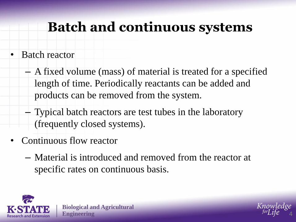
• Batch reactor
– A fixed volume (mass) of material is treated for a specified
length of time. Periodically reactants can be added and
products can be removed from the system.
– Typical batch reactors are test tubes in the laboratory
(frequently closed systems).
• Continuous flow reactor
– Material is introduced and removed from the reactor at
specific rates on continuous basis.

Biological and Agricultural Engineering
Batch reactor
5
• For a batch reactor, NAf = NAe =0, therefore,
−𝑑𝑁𝐴𝑑𝑡
= 𝑉
−𝑟 𝐴 𝑑𝑉
• If the reactor is perfectly mixed, the rate of reaction is the same
throughout,
− 𝑟 𝐴 = −1
𝑉
𝑑𝑁𝐴
𝑑𝑡= −
1
𝑉
𝑑(𝐶𝐴𝑉)
𝑑𝑡= −
𝑑𝐶𝐴
𝑑𝑡−𝐶 𝐴
𝑑𝑙𝑛𝑉
𝑑𝑡
• With constant volume,
− 𝑟 𝐴 = −𝑑𝐶 𝐴𝑑𝑡
Biological and Agricultural Engineering
The Continuous-Flow Stirred Tank Reactor (CSTR)
6
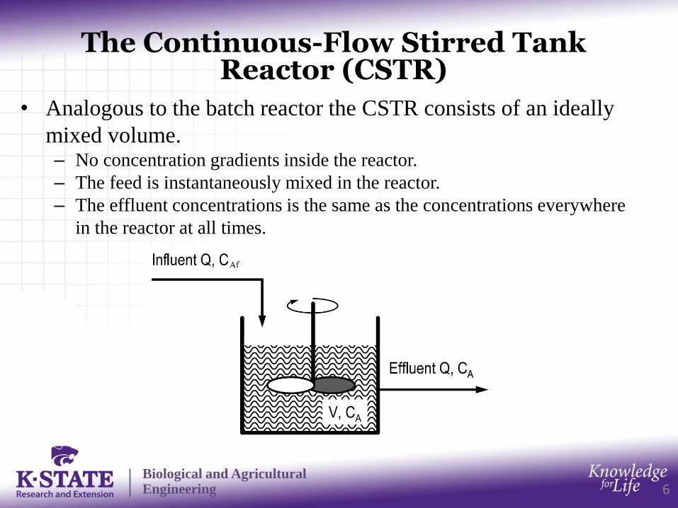
• Analogous to the batch reactor the CSTR consists of an ideally
mixed volume.– No concentration gradients inside the reactor.
– The feed is instantaneously mixed in the reactor.
– The effluent concentrations is the same as the concentrations everywhere
in the reactor at all times.

Biological and Agricultural Engineering
Mass balance for CSTR
7
Assuming steady state and the rate of the reaction is uniform
throughout the reactor.
NAf = NAe + 𝑉 −rA 𝑑𝑉 +𝑑𝑁
𝐴
𝑑𝑡= NAe + rA𝑉
Thus, the volume of CSTR
V = NAf−NAe
−rA= QfCAf−QeCA
−rA
For first order reactions (with rA = -kCA), when Qf=Qe=Q
𝐶𝐴
𝐶𝐴𝑓
= 1
1+𝑘(𝑉
𝑄)
V=QfCAf−QeCA
−kCA
=𝑄
𝑘
𝑥
(1−𝑥)
Where V/Q has unit of time , and is called the mean detention time or
residence time of the reactor td. x = 1-CA/CAf is the conversion.
Biological and Agricultural Engineering
The Plug-Flow Reactor (PFR)
8
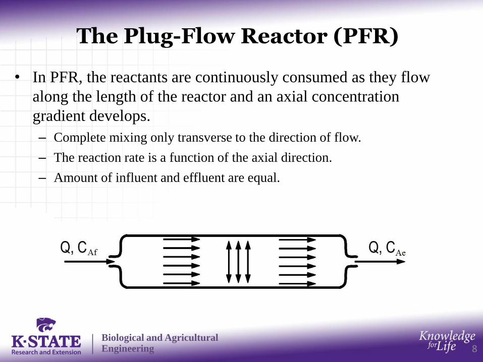
• In PFR, the reactants are continuously consumed as they flow
along the length of the reactor and an axial concentration
gradient develops.
– Complete mixing only transverse to the direction of flow.
– The reaction rate is a function of the axial direction.
– Amount of influent and effluent are equal.

Biological and Agricultural Engineering
Mass balance for PFR
9
Assuming steady state, and the rate rA is constant within a small
volume element ΔV.
NA (z+Δz) - NA (z) = -rAΔV
dNA = -rA dV = -rAAcdz
In which Ac is the cross-sectional area.
For first order reactions (with rA = -kCA)
Q𝑑𝐶
𝐴
𝑑𝑉= -kCA
𝐶𝐴
𝐶𝐴𝑓
=exp(-kV/Q), V =𝑄
𝑘ln𝐶𝐴𝑓
𝐶𝐴
=𝑄
𝑘ln
1
1−𝑥
If 50% 0f CAf has to be converted into products, the v=0.693Q/k is the
reactor volume required.

Biological and Agricultural Engineering
Comparison of reactor volume for a CSTR and a PFR
10
VCSTR =𝑄
𝑘
𝑥
(1−𝑥)
VPFR = 𝑄
𝑘ln
1
1−𝑥
VCSTR
VPFR
=𝑥
(1 − 𝑥)ln1
1 − 𝑥If the desired conversion is xA=0.6, then the ratio of volume is 1.63.
Thus a 63% larger volume of CSTR than that of a PFR is required to
achieve a 60% conversion.
An ideal PFR can achieve the same conversion as that of a CSTR but
using a much smaller volume of the reactor.

Biological and Agricultural Engineering
Comparison of concentrations in a CSTR and a PFR
11
𝐶𝐴𝐶𝐴𝑓
Mean residence time td
For CSTR, 𝐶𝐴
𝐶𝐴𝑓
= 1
1+𝑘𝑡𝑑
1
For PFR, 𝐶𝐴
𝐶𝐴𝑓
=exp(-ktd)

Biological and Agricultural Engineering
General design equations fro CSTR and PFR
12
For CSTR,
V = NAf−NAe
−rA=
NAfx−rA
For PFR,
dV = -1
rAdNA, V =NAf −
1
rA𝑑𝑥
The rate of disappearance of A, -rA, is a function of concentrations
of the reactants, and thus can be expressed as a function of the
conversion x.

Biological and Agricultural Engineering
Two CSTR in series
13
Consider two CSTR in series, if 40% conversion is achieved in the
first reactor, and the second reactor accomplished 80% overall
conversion of reactant A entering reactor 1. What are the total
reactor volume saved comparing with using only one CSTR?
-1
rA
x0.80.60.40.2 1.0
Volume
savedV2
V1

Biological and Agricultural Engineering
Two PFR in series
14
Can we save any volume by using two PFR in series?
-1
rA
x0.80.60.40.2 1.0
V2V1

Biological and Agricultural Engineering
One CSTR and one PFR in series
15
How to arrange to minimize total reactor volume? It depends on
shape of the curve and the intermediate concentration.
-1
rA
x
0.80.60.40.2 1.0
V2
V1
-1
rA
x
0.80.60.40.2 1.0
V2V1

Biological and Agricultural Engineering
Example: CSTR model for a surface impoundment
16
Surface impoundment is often used for treatment of wastewater, and
it can be considered as a CSTR with complete mixing within the
aqueous phase. The average biodegradation rate is 0.05 h-1; the rate
constant for settling of biomass is estimated to be 2.2×10⁻⁶ h-1; the
rate constant for volatilization is 2×10⁻⁵ h-1. Estimate the reduction
efficiency when the mean detention time is 1 days.
Solution:
The overall rate constant k=0.05 h-1.
Assuming it is a CSTR, 𝐶𝐴
𝐶𝐴𝑓
= 1
1+𝑘𝑡𝑑
=1
1+0.05×24=0.45.
The reduction efficiency is around 55%.

Biological and Agricultural Engineering
Example: FPR model for a combustion incinerator
17
Consider a waste containing benzene being incinerated using an
airstream at a velocity of 5 m/s. A typical length of the incinerator
chamber is 10 m. Typical inlet temperature is 900ºC and outlet
temperature is 800ºC. The average rate constant is estimated to be
around 4 s-1. Estimate the reduction efficiency
Solution:
The detention time td=10/5=2 s.
Assuming it is a PFR, 𝐶𝐴
𝐶𝐴𝑓
=exp(-ktd) =exp(-4×2)=0.0003
The reduction efficiency is around 99.97%.

Biological and Agricultural Engineering
CSTR or PFR?
18
• For many degradation reactions PFR result in better performance than the
CSTR (back mixed). However, for many processes, mixing is a central
element of the process, e.g., with aeration (gas exchange), generation of
turbulence for the acceleration of flocculation and precipitation. Mixing
contradicts the characteristics of the PFR.
• Therefore, intermediate solutions with defined mixed ranges (e.g., a cascade
of CSTR, or PFR with turbulence) are used. These solutions combine the
advantages of mixing with the extra performance offered by PFR.
• Also recirculation (i.e., return of sludge and internal recirculation in the
activated sludge process) leads to back mixing and brings the behavior and
performance of a PFR closer to those of a mixed system.
• Back mixed systems are a necessity for autocatalytic processes. Back mixing
brings the catalyst from where it is produced back to the influent of the
reactor, where it is most required. Many microbial processes are autocatalytic,
thus completely mixed or back mixed reactors or systems with recirculation
flow are typical for biological treatment systems.

Biological and Agricultural Engineering
Residence time distribution
19
• The residence time distribution of a chemical reactor is a
probability distribution function that describes the amount of
time a fluid element could spend inside the reactor. Since each
fluid element must at some time leave the reactor, the integral
under the residence time distribution is unity.
• The residence time distribution is often used to characterize the
mixing and the internal transport processes in a reactor. The
comparison between the behavior of real reactors and their ideal
models is useful for troubleshooting existing reactors, as well as
in designing future reactors.
Biological and Agricultural Engineering
Residence time distribution of CSTR
20
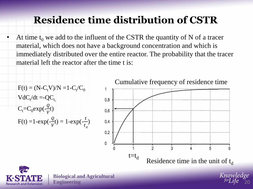
• At time t0 we add to the influent of the CSTR the quantity of N of a tracer
material, which does not have a background concentration and which is
immediately distributed over the entire reactor. The probability that the tracer
material left the reactor after the time t is:
F(t) = (N-CtV)/N =1-Ct/C0
VdCt/dt =-QCt,
Ct=C0exp(-𝑄
𝑉t)
F(t) =1-exp(-𝑄
𝑉t) = 1-exp(-
𝑡
𝑡𝑑
)
Cumulative frequency of residence time
Residence time in the unit of td
t=td
Biological and Agricultural Engineering
Example
21
• A CSTR in the steady state has an influent of 100 m3 /h. What
size is required such that 90% of the water remain in the reactor
for more than 1 hour?
• Solution:
F(t) =1-exp(-𝑡
𝑡𝑑
) =0.1
𝑡
𝑡𝑑
= -ln(1-0.1) = 0.105
𝑡𝑑 = t/0.105= 1/0.105 =9.5 h
V = Q 𝑡𝑑 = 100×9.5 = 950 m3

Biological and Agricultural Engineering
Nonideal reactors
22
• The reactors we have discussed thus far assumed ideal flow
patterns,
– As one extreme, no back mixing in PFR;
– As the other extreme, complete mixing in CSTR.
• Natural environmental reactors fall somewhere between the two
ideal reactors. The deviations are caused by fluid channeling,
recycling, or stagnation points in the reactor.
• Two models have been used to explain nonideal flows in reactors.
– Dispersion model: introduce a axial dispersion coefficient Dax. When Dax=0,
we have PFR; and as Dax∞, we have CSTR.
– Tanks-in-series model: model dispersion by using a series of CSTR.