pda tech report 26 (draft) - pharmanet · 6.10 challenge test methods 6.11 test organism viability...
TRANSCRIPT
PDA Technical Report No. 26
Sterilizing Filtration of Liquids
Final DraftAugust 28, 1997
FINAL_07.PDF

Page 2
PDA Sterile Filtration Committee
John H. Robertson, Pharmacia & Upjohn, Inc. (Co-chair)James D. Wilson, Pharmaceutical Systems, Inc. (Co-chair)Frank Bing, Abbott Laboratories, Inc.Margaret Byrd, Glaxo Wellcome Inc.Teresa M. Feeser, Ph.D., Merck & Company, Inc.Maik W. Jornitz, Sartorius AGRichard V. Levy, Ph.D., Millipore CorporationRussell E. Madsen, PDAJerold M. Martin, Pall CorporationLaura S. Meissner, Meissner Filtration Products, Inc.Theodore H. Meltzer, Ph.D., Capitola Consulting Co.Fred M. Nordhauser, Gelman Sciences, Inc.Joeseph Pietro, Eli Lilly & CompanyHans G. Schroeder, Ph.D., International Consultants Assoc.Paul S. Stinavage, Ph.D., FDAA. Mark Trotter, Sartorius CorporationPeter J. WaibelMichael J. Wikol, W. L. Gore & Associates, Inc.Peter Wolber, Sartorius Separations, Inc.Bob L. Weber, Millipore CorporationJim Wilder, Memtec America Corporation

Page 3
PDA TECHNICAL REPORT NO. 26 STERILIZING FILTRATION OF LIQUIDS
Table of Contents
1. INTRODUCTION
2. PHARMACEUTICAL FILTRATION - HISTORICAL HIGHLIGHTS
3. HOW FILTERS WORK3.1 Size Exclusion3.2 Other Retention Mechanisms3.3 Bioburden Retention Probability3.4 Pore Size Rating
4. FILTER SELECTION AND CHARACTERIZATION4.1 Filter Types4.2 Filter Configurations4.3 Particle Shedding4.4 Extractables4.5 Chemical Compatibility4.6 Thermal Stress Resistance4.7 Hydraulic Stress Resistance4.8 Toxicity Testing4.9 Bacterial Challenge Testing4.10 Physical Integrity Testing
5. PHYSICAL AND MECHANICAL CHARACTERISTICS5.1 Filtration Rate and Clogging (Throughput)5.2 Fluid/Piping5.3 Fluid/Filter5.4 Physical and Structural Limitations
6. STERILE FILTER VALIDATION / BACTERIAL RETENTION6.1 Factors Influencing Microbial Retention6.2 Considerations for Bacterial Retention Validation Studies6.3 Challenge Organism Selection Criteria6.4 Culture Maintenance6.5 Culture Conditions and Standardization6.6 Effective Challenge Concentration6.7 Challenge Level6.8 Aggregation6.9 Culture Viability6.10 Challenge Test Methods6.11 Test Organism Viability6.12 Testing Procedure and Protocol Development
Page 4
6.13 Nonbactericidal Processes and Fluids6.14 Surrogate Fluids6.15 Bacteristatic/Bactericidal/Nondispersive Challenge Fluids
6.15.1 Product Use at Reduced Exposure Time6.15.2 Modify Process6.15.3 Modify Formulation6.15.4 Resistant Indigenous Bioburden Use
6.16 Filter Medium versus Device6.17 Pressure Differential and Flow Rate6.18 Duration6.19 Downstream Sampling6.20 Assay Membrane Selection6.21 Results Interpretation6.22 Product Bioburden6.23 Filter Configuration Change
7. INTEGRITY TESTING7.1 Integrity Testing Theory7.2 Relationship Between Integrity Test Results and Microbial Retention7.3 Product-Wetted versus Water-Wetted Integrity Testing7.4 Upstream Testing without Downstream Manipulation Utilizing Automated Integrity
Test Instruments7.5 When a Sterilizing Grade Filter Should be Integrity Tested7.6 Failure Analysis/Trouble Shooting
8. FILTER STERILIZATION8.1 Steam Sterilization
8.1.1 Autoclave Sterilization8.1.2 Sterilize-in-Place
8.2 Irradiation Sterilization8.3 Gas Sterilization
APPENDICESA. Pore Size EstimationB. Toxicity and Filter Extractable TestingC. Filter Validation RecommendationsD. Nondestructive Physical Integrity Test Methods
BIBLIOGRAPHY

Page 5
1.0 INTRODUCTION
Sterilizing filtration is the process of removing all microorganisms, excluding viruses, from a flui dstream. A sterilizing grade filter must remove all microorganisms present in a fluid stream withoutadversely affecting product quality. This technical report is intended to provide a systemati capproach to selecting and validating the most appropriate filter for a sterilizing filtration application.
Early, careful screening of potential filter types and configurations can result in fewer technical andregulatory problems, fewer delays, more efficient product processing and greater sterility assurance.
2.0 PHARMACEUTICAL FILTRATION/HISTORICAL HIGHLIGHTS
In the early 1900s, the first parenteral drugs were manufactured on an industrial scale. The nee darose to find a suitable sterilization method for heat-sensitive products that could not be autoclavedin the final container, i.e., had to be aseptically processed. Later, filtration to remove subvisibl eparticulates from parenteral preparations, particularly solutions introduced intravenously, was foundto be important.
It is not surprising that pioneering work in the field of germ removal by filtration (sterilization b yfiltration) also was underway from about 1900 to 1930. In the industrial field, three paths wer epursued: porcelain filter cartridges, asbestos-cellulose layers and membrane filters.
Initially, porcelain filters by Chamberlain were used in pharmaceutical production. However ,problems with cleaning these permanent filters and the danger of cross-contamination led to thei rreplacement. The first filter medium to be used on an industrial scale worldwide for almost 50 yearswas a cellulose-asbestos filter known as the Seitz EK Filter (EK - Entkeimung, "germ removal") .Since the mid-1970s this filter has been forced off the market because of the asbestos fiber issue .Collodion membranes, manufactured by users themselves, were employed in bacteriologica llaboratories as early as the first decade of the 20 century. The forerunner to the membrane filter wasth
developed by Zsigmondy and Birchmann who patented a graded series of membranes in 1918. TheSartorius-Werke Aktiengesellschaft, Göttingen, Germany, refined the Zsigmondy process and in 1929began the commercial production of membrane filters on a small scale. The first membrane disks ledto the replacement of porcelain filter cartridges in pharmaceutical production. There still was a lackof efficient, large surface area, inexpensive membrane filters for use in large parenteral batc hproduction. The membrane filter cartridges, especially the pleated cartridges that entered the marketin the 1970s, were a step in the right direction.
There still were problems, as the retention rate for bacteria was unacceptable to the pharmaceuticalindustry. The problem was examined systematically, and a collabor ation between filter manufacturersand pharmaceutical companies developed basic principles that would ensure safety in sterilization byfiltration.
The homogeneity of the membranes in the sponge-like labyrinth system and the concern about thepotential for interfering "large pores" initially led to the use of double-layer membranes. Additionally,defects in the cartridges arose from the folding and welding, or gluing of the membranes, as well asdefective seals and damage during autoclaving. Newly developed integrity test equipment helped,
Page 6
allowing accurate measurements to assess these defects. Improved filter manufacturing techniqueseventually eliminated these defects.
Until the late 1960s, 0.45 m-rated membranes were considered "sterilizing grade" filters, and wereused successfully in the sterilizing filtration of parenterals. Such filters were qualified using 0.6x1 mSerratia marcescens, a standard bacterium for qualifying analytical membranes used for water qualitytesting (ASTM, 1980). In the mid-1960s, however, Dr. Frances Bowman of the FDA observed a0.45 m "sterile-filtered" culture medium to be contaminated with an organism, subsequently shownto penetrate 0.45 m-rated membranes repeatedly in small numbers at challenge levels above 10 -104 6
per cm² (Bowman et al., 1967).
Bowman also observed that the next finer grade commercial membrane (nominally 0.22 m-rated)effectively retained this organism at similar challenge levels. This 0.3x0.6-0.8 m contaminant wasidentified as Pseudomonas diminuta (currently reclassified as Brevundimonas diminuta), andregistered with the American Type Culture Collection (ATCC) as C ulture No. 19146. This strain hasbeen accepted widely by filter manufacturers and industry as the standard challenge organism fo rqualifying sterilizing grade membrane filters (ASTM, 1983; ISO, 1995).
Following the broad acceptance of B. diminuta, FDA incorporated demonstration of its retention inthe definition of a sterilizing filter.
The use of this microorganism provides several advantages:- Originally a process stream isolate, it is therefore a realistic potential problem organism.- Generally regarded as nonpathogenic to humans, ordinary microbiology laboratories can use it
without major biohazard concerns.- It can be consistently cultured under controlled conditions to yield very small, monodisperse d
cells with a narrow size distribution. These can penetrate 0.45 m filters reproducibly in smallnumbers at high challenge levels, thus representing a potential worst-case challenge.
The disadvantages of B. diminuta are:- It is not viable in many pharmaceutical formulations.- It may not be the smallest bacterium potentially encountered in all formulations, and thus may not
represent bioburden organisms in terms of morphology and physiology.- In spite of being stable, batch-to-batch variation in its morphology (size) should be examined.
3.0 HOW FILTERS WORK
It is widely believed that filters work by permitting fluid passage through their pores, retainin gparticles too large to fit through these apertures. This mechanism of particle arrest or capture i scalled variously sieve retention, physical capture, direct interception, size exclusion, etc. This viewis based on the axiom of solid geometry that a particle too large to fit into a pore is incapable o fpassing through it.
Although size exclusion is an important, and perhaps for sterilizing filters the most reliable ,mechanism of filtration action, it may not be the only one. Indeed, particles small enough to enterand pass through filter pores may be captured by becoming adsorptively attached to pore walls. The

Page 7
effectiveness of adsorptive sequestration mechanisms depends upon filtration conditions. Man ydifferent operational conditions govern a filter's adsorptive removal of particles, including applie ddifferential pressure, flow rate, number of particles present, and the liquid vehicle's makeup in termsof its surface tension, pH and ionic strength, among other factors. All must be considered an dunderstood in filter validation.
The best way to assess whether an individual membrane filter can produce a sterile effluent is t ochallenge the filter with a large number of organisms and measure the retention. Unfortunately, thisis a destructive procedure that leaves the tested filter contaminated by test organisms an dsubsequently unusable for product filtration. It is possible, however, to assess the suitability of afilter's sterilizing action by subjecting it to nondestructive integrity tests, which can be correlated tomicrobial retention.
3.1 Size Exclusion
As previously noted, a particle too large to pass through a filter pore becomes arrested by the spatialrestraint. This serves to separate it from the conveying fluid in which it is suspended. This type ofparticle capture is called size exclusion. Size exclusion is a combination of surface screening an dentrapment within the filter matrix.
If each particle challenging the filter is too large to pass through the pores, the number of particlesdoes not matter; none will pass the filter. Filter efficiency, the comple teness with which a filter retainsparticles confronting it, also is independent of the applied differential pressure, as long as tha tpressure does not deform the particle or the pore, causing a failure in sieve retention. Differentia lpressure is the difference in pressure on opposite sides of the membrane, and governs the flow of theliquid or gas through the filter.
3.2 Other Retention Mechanisms
Other mechanisms of particle removal include, but are not necessarily limited to adsorptiv esequestration, inertial impaction and diffusional interception. Particles may be small enough to enterthe filter pores but still may be captured by the filter, indicating that particle retention may dependupon other operating conditions governing the filtration. These effects are important if bacteri asmaller than the pore size are present.
3.3 Bioburden Retention Probability
In situations where contaminants are not all retained by size exclusion, the outcome can be said tobe probabilistic. Figure 1 shows a bacterium smaller than the pore size entering a pore. It may eithertraverse the pore to leave with the flow, or encounter the pore wall and become adsorptively arrestedby Van der Waals forces, or residual or secondary valence forces. Which situation prevails is a resultof probabilities. Regardless of the challenge level, for a filter that is not plugged, the probability thatany particular particle will penetrate the filter is the same for any identical particle. The greater thenumber of particles, that is, the higher the challenge density, the more likely it becomes that som eparticles will escape capture. The lower the organism population confronting the filter, the better thefilter performs.

Page 8
Figure 1 Alternate paths for particles entering pores.
The effects of differential pressure also must be considered. The lower the differential pressure, thegreater the likelihood of organism retention. The longer a particle or organism remains within a porepassageway, the more likely it is to encounter the pore wall and be adsorbed. Conversely, at higherdifferential pressure, the velocity of the liquid through the pore increases and the residence tim edecreases, resulting in lower probability of particle capture. There is, therefore, a probabilistic natureto the adsorptive capture, expressed by the inverse relationship of adsorptive sequestration to th edifferential pressure level.
For particles not retained by size exclusion, various investigators have shown that such properties aspH, surface tension, ionic strength and viscosity may influence retention by microporous membranes.Such dependency may be indicative of adsorptive retention. The vehicle also may affect bacteri apresent, by changing their size or morphology. Such changes might result in a nonsterile filtrate.
It should be emphasized that the bioburden level can influence filtration process efficacy. For thi sreason, the bioburden should be kept as low as possible at each stage of the process. Filters exhibitmaximum efficacy when the bioburden is minimized. Said another way, the probability of microbialpassage is minimized when the bioburden is low. Bioburden should be routinely monitored.
3.4 Pore Size Rating
The rating of filters always has been controversial, primarily due to the lack of manufacture runiformity in measuring pore sizes. Thus, pore size rating has limited value in predicting microbialretention or physical integrity test values, or providing a basis of comparison between differen tmaterials of construction and manufacturers.
Since the process of classifying a sterilizing grade filter by pore size has limited value, it has bee nreplaced by defining the filter in terms of its bacterial retention (FDA, Aseptic Processing Guideline,1987). Classically, a sterilizing grade filter has been defined as a filter which will retain 10 cfu of B.7
diminuta ATCC 19146/cm of effective filter surface area, under specified conditions. A discussion2
of pore size ratings is found in Appendix A.

Page 9
4.0 FILTER SELECTION AND CHARACTERIZATION
Selecting a sterilizing grade filter requires consideration of many important issues, such as materialsof construction and their compatibility with the product. The selection also should consider th eprocessing characteristics, including the volume of product filtered, flow rate, pressure differential,temperature and the chemical characteristics of the product.
The following sections consider important topics in determining the best filter for a given application.More detailed discussion on these topics is contained later in this report.
4.1 Filter Types
Current available materials of construction include, but are not limited to polymers such as celluloseesters, nylon, polyesters, polytetrafluoroethylene, polyvinylidene flouride, polycarbonate ,polypropylene, polyethersulfone and polysulfone. Minor components, such as surfactants may b eadded to the filter to enhance wettability, or render the filter membrane hydrophilic or hydrophobic.Hydrophobic means that the membrane pores are not easily penetrated by water or aqueous streams.Hydrophilic means that the pores of the membrane are readily penetrated by water or aqueous fluids.
Whether the filter is hydrophilic or hydrophobic also greatly affects its ability to properly serve in agiven process. Generally, hydrophilic filters are used for aqueous based liquid processes, whil ehydrophobic filters are used for solvent, vent and gas applications.
4.2 Filter Configuration
During filter evaluation, it is best to consider all processing variables so the appropriate filter surfacearea and configuration can be selected. There are three basic types of filter configurations generallyaccepted for sterilizing products: flat stock membranes, preassembled capsules and membran ecartridge assemblies.
Flat stock membranes have been used for many years. Single membranes in reusable holder sgenerally are considered suitable for small-scale sterilizing filtration. Multiple disc assemblies ar esuitable for larger filtration volumes. However, there are advantages to working with small cartridgesor self-contained capsules, which are more practical and easier to handle than flat stock membranes.Mid-sized operations such as developmental pilot scale or clinical manufacturing are good candidatesfor self-contained, disposable capsule filters, while cartridge filters should be considered for largerscale operations or processes. Multiple cartridge configurations are suited to the large-scal eproduction environment.
The appropriate filter surface area for a particular sterilizing filtration application can be estimatedfrom laboratory experiments utilizing the identical filter membrane. Fl ow rate and particulate removalstudies performed on 47 mm discs usually may be extrapolated to larger configurations, but th eeffects of filter configuration and the process stream must be considered. Considerations may includepleating, stacking and piping, among others. Since flow rates are very se nsitive to system restrictions,undersized tubing and fittings should be avoided.

Page 10
4.3 Particle Shedding
Particulate contamination from the filter and process must be evaluated and considered, since al lfilters may shed particles. Tests should be conducted at various flow rates in order to select th eappropriate filter and establish process variables.
4.4 Extractables
The USP outlines a series of tests and guidelines for extractables from plastics. Typically, most filtercandidates will pass these tests, but a relative measure between candidates can provide valuabl einformation.
Potential extractable sources from sterilizing filters may include surfactant and wetting agents ,additives used in the plastic component manufacture, manufacturing debris, and materials an doligomers of materials of construction.
Manufacturers can provide appropriate data on extractable levels and identities from their filter s(Appendix B includes a detailed discussion). This may help users identify extractable componentswithin their product filtrates. Extractables can be classified as toxic or nontoxic, and should b edemonstrated to be nontoxic. It is the user's responsibility to demonstrate that the product does notcontain objectionable levels of extractables from the filter. Processing conditions, includin gsterilization, must be considered when performing extraction studies.
Suitable analytical techniques for measuring extractable levels and types include "bulk" analytica lmethods, such as non-volatile residue and Fourier transform infra-red spectroscopy (FTIR), appliedto an extract without fractionation, to avoid possible loss of unknown analytes in workup. Analyticaltechniques suitable for further measuring of extractable levels and types include gas chromatography(GC), high pressure liquid chromatography (HPLC), capillary electrophoresis (HPCE) and ga schromatography mass spectrometry (GC-MS). Where applicable, standardized and/or compendialmethods should be followed, e.g., ASTM, USP.
Most filter manufacturers test for extractables using a standard solvent (typically water). The filteruser is responsible for obtaining extractable data for the drug product formulation. When the productformulation precludes the use of standard analytical methodology, a suitable model may be used tomeasure the extractable levels. The model must, however, exhibit similar physical and chemica lcharacteristics.
4.5 Chemical Compatibility
When considering chemical compatibility, it is important to include al l of the filter system componentsunder investigation. In addition to the membrane, these include support materials for the membrane,cartridge shell and housing material, and o-rings used to seal the cartridge and housing. A mor esubtle contributor to compatibility issues is the possible presence of filter component treatments.
Numerous chemical interaction possibilities exist in a filter system. The effects of these interactionsmust be adequately characterized prior to filter selection. A simple chemical compatibility chart will
Page 11
often not provide enough information for predicting filter system compatibility, thereby requirin gadditional testing. Integrity testing is a "physical test" that relates to microbial retention and is adeterminant of compatibility.
4.6 Thermal Stress Resistance
Steam is one of the major sterilization methods for filters. It is extremely important that the filte rmembrane and support structures be stable under the steam sterilization pressure, temperature andtime process conditions. In addition, many processes may require the product filtration at elevatedtemperatures. Again, the filter must withstand the rigors of the process.
4.7 Hydraulic Stress Resistance
During product filtration, the filter will undergo varying pressure requirements. It may experiencelow to extremely high pressure differentials, due to the product processing characteristics. Duringvalidation, the process filtration pressures should be approximated. If the filter will be subjected tohigh hydraulic stress, this also should be simulated in the validation process.
4.8 Toxicity Testing
Filters should not be constructed of materials which are toxic or m ay affect product quality if releasedinto the fluid stream. Filter suppliers typically provide toxicity testing data which may suppor tcustomers' validation requirements. However, many filter users choose to submit typical stock filtersamples for independent testing to supplement manufacturer information. Appendix B offers adetailed discussion of filter toxicity testing.
4.9 Bacterial Challenge Testing
The bacterial challenge test serves two major functions. The filter manufacturer uses it to classif yfilters as sterilizing grade if the filter provides a sterile effluent with a minimum of 10 cells of B.7
diminuta ATCC 19146/cm of effective filter surface area.2
Bacterial challenge tests also are required to validate the sterilizing filtration process of a specifi cproduct. The filter challenge test must be performed with actual product or, where justified, suitablesurrogate fluid. This topic is dealt with in more detail later in this technical report.
4.10 Physical Integrity Testing
Integrity testing is required for all sterilizing filtration applications. Physical integrity tests are basedupon the gas flow rate through a filter wetted with a suitable liquid, as a function of the applied testpressure. Hydrophobic filters used for liquid filtration also can be tested by measuring th emembrane's resistance to water flow as a function of applied pressure. Manual and automated testmethods are available. The chosen integrity test method and acceptance criteria must be validatedand must correlate to bacterial retention.
Page 12
5.0 PHYSICAL AND MECHANICAL CHARACTERISTICS
A number of characteristics should be considered in choosing a sterilizing grade filter. The filter' scompatibility with the process is dependent primarily upon the materials of construction of th emembrane, upstream and downstream supports, encapsulation materials and the cartridge sealin gelastomers (o-rings and gaskets). While many of these materials meet a wide range of requirements,specific processes may favor one over another.
In addition to materials of construction, a number of other characteristics should be considered in asterilizing filter. Some characteristics affect the filter's compatibility with a given process. The filterextractables (molecular and elemental contamination) should be considered seriously. Filter particleshedding also can be a factor. Filters have some extractables and may shed particles initially, bu tprocess compatibility helps to minimize this. Recognizing this, filter manufacturers generall yrecommend flushing the filter before use. Additionally, the filter should be sterilizable by the methodof choice. In some cases, the filter must be able to withstand multiple sterilization cycles. The filtermust be validated for its intended use, including sterilization and fluid stream processing. All filtercomponents must meet applicable compendial requirements such as USP Biological Reactivity Tests,general chapters <87> and <88>.
Other physical characteristics which affect the filter's ability to perform properly include physica ldimensions, configuration, end cap design (cartridges) and end connections (capsules). The physicalcharacteristics are important from not only installation considerations, but because subtle differencescan create bypass problems that could lead to process contamination.
5.1 Filtration Rate and Clogging (Throughput)
Sterilizing filter flow rates measure the amount of fluid flow through a given area, such as a squarefoot of media, cartridge or capsule, for a given period of time, usually one minute at a given pressuredrop. Flow volumes typically are measured in terms of gallons, liters or milliliters. Alternately, thepressure drop for a given volume flow per unit of time may be expressed as pressure drop at aparticular flow rate, e.g., psid/gpm. The sterilizing filter flow characteristic is determined by th eamount of membrane surface area and the membrane's permeability. Membrane permeability i sdetermined primarily by the total porosity (void volume), membrane thickness , and, to a lesser degree,effective pore size.
Several basic relationships exist between a filter’s flow rate and its porosity, thickness, effective poresize and surface area. The filter flow rate is proportional to the surfa ce area of its membrane, but maynot be linear. Generally, there is an inverse relationship between membrane thickness and flow. Flowrate also has a direct relationship with the membrane's effective pore size (retention) rating.
Construction of the filter device and housing design can affect its flow. For a fixed membrane area,permeability and construction, larger pore size rated filters typically provide higher flow. The throughput or life of a sterilizing filter generally is determined by the membrane's capability toretain particles, and the amount of surface area exposed to the process. As the filter remove sparticles and bacteria, the flow begins to decline, unless differential pressure is increased. Th e

Page 13
throughput life of a sterilizing filter is measured as the amount of time the filter can remain on-stream,before an unacceptably high differential pressure or loss of flow occurs. Pre-filters can appreciablyaffect filtration rate and filter life.
5.2 Fluid/Piping
The piping and cartridge housing used in the process must be compatible with process parameters andexhibit acceptable fluid dynamic principles.
5.3 Fluid/Filter
Many possible interactions exist between a process fluid and a sterilizing filter. The consequencesof these interactions may manifest themselves in a variety of measurable changes. If the fluid an dmembrane are drastically incompatible, physical degradation of the membrane structure can lead tolarge membrane defects which will reduce filtration efficiency and cause contamination as the filtersheds particulates downstream.
Several membrane polymer types also can swell in the presence of certain chemicals, which may affectboth flow and physical integrity test values. Measurable differences have been documented in bothflow and physical test values as a result of this swelling. In addition to the deleterious effects o freduced flow through the membrane, physical integrity result changes can cause concerns about themembrane structure and its ability to retain particles.
Simple physical tests can detect these types of incompatibility. Consideration of any sterilizing filterexhibiting such characteristics after exposure to the process fluid should be re-evaluated.
5.4 Physical and Structural Limitations
Filters are limited by their physical strength and ability to retain integrity under handling and processstress conditions. While sterilizing membranes themselves may be relatively fragile, process filterstypically incorporate resilient nonwoven polymeric layers and rugged plastic hardware which makethe elements quite strong. These constructs still may be subject to damage under rough handling orsevere process conditions.
There also are several pressure aspects that must be considered. The inlet pressure to the filter i simportant to ensure that there is no potential for structural deformation of the support structure. Thedifferential pressure across the membrane must be accounted for, to comply with the filte rmanufacturer's recommended limits. Maximum differential pressure normally is stated as a functionof temperature.
Another aspect that must be considered is the direction of the applied pressure. Filters may hav edifferent maximum pressure differentials in forward and reverse flow directions. These pressur edifferentials may also be temperature dependent. For example, a maximum limit of 75 psi (5 bar )differential at 25 C in the forward direction versus 50 psi (3.5 bar) differential in the reverse directionat 25 C and a maximum limit of 5 psi differential in either direction at 121 C.
Page 14
When pressure limits are being evaluated, drug manufacturers should consider two areas of specialconcern. The first is in steam in place (SIP) sterilization pressure, where users should consider theeffect of elevated temperature on the filter's differential pressure limitation. The second is hydraulicstress, which may increase dramatically if a valve is opened too quickly, or during a filling operationwhich does not incorporate a surge tank. In these cases, the filter may be exposed suddenly t opressures in excess of full line pressure. Differential pressure across the filter must not exceed thelimit set by the filter manufacturer at the specified temperature.
6.0 STERILE FILTER VALIDATION/BACTERIAL RETENTION
Bacterial challenge testing, using ASTM method F838-83 or comparable methodology, is performedby the filter manufacturer to classify the retention capability of the filter membrane or device. Theuser, or designated test facility, then demonstrates complete microbial removal from each product orproduct family using a representative challenge microorganism. It is important to realize that thesetwo filter testing concepts are not interchangeable and must be independently validated. The goal ofthese tests is to prove that the production process generates a sterile effluent.
6.1 Factors Influencing Microbial Retention
Those factors potentially affecting microbial retention include filter type (structure, base polymer ,surface modification chemistry, pore size distribution, thickness), fluid components (formulation ,surfactants, additives), fluid properties (pH, viscosity, osmolarity, ionic strength), process conditions(temperature, pressure differential, flow rate, time) and the specific characteristics of the actua lbioburden in the product.
One should also consider the potential of product formulations or process conditions to affect cellsize or other physiological or morphological microorganism attributes which might allow thei rpassage.
6.2 Considerations for Bacterial Retention Validation Studies
Sterilizing filtration process validation should include "worst-case" scenarios, using the filte rmembrane or device selected for the product.
The following should be considered when conducting product bacterial retention validation o nmembrane filters.
1. When possible, at least three filter membrane lots should be included in product bacterialretention validation studies. The exact number of filters and the test design will depend uponthe process.
2. At least one of the filter membrane lots used for bacterial retention validation should havea pre-filtration, water wet, physical integrity test value at or near the filter manufacturer' sspecification limit. Other filter parameters, including thickness, should be representative o ftypical production membranes.

Page 15
3. The membranes used for fabricating process filters must meet or exceed the integrity testvalue established during product-specific bacterial retention testing.
4. Membrane physical integrity test values from bacterial retention validation studies shouldbe included in the test report. The physical integrity should be determined prior to challengetesting, using water, product or other wetting fluid for which specifications exist.
The appropriate physical integrity test value for a specific product/filter combination can beestablished independently of the microbial retentivity test by testing a number of different lotsof product against a number of different lots of the same filter membrane. Using this data,a physical integrity test value for routine physical integrity testing that takes into account themanufactuer's lower physical integrity test limits can be calculated .
Although the physical test can be established independently of the microbial retentivit yvalidation, it is only valid provided it agrees with the physical integrity values obtained forthe filters used during microbial retentivity testing.
5. If the test organism is recovered downstream of any filter after the product bacteria lchallenge, an investigation must be performed. If such investigation confirms penetration ofthe filter by the test organism and the filter meets its integrity test specification, then th eapplicability of this filter under these process conditions must be reconsidered.
6.3 Challenge Organism Selection Criteria
The challenge bacteria should be small enough to challenge the retentivity of the sterilizing grade filterand simulate the smallest microorganism that may occur in production.
A sterilizing filter is defined as one that retains a minimum challenge of 10 cfu of P. diminuta/cm²7
of filter surface (FDA, 1987). FDA does not recommend any single protocol or challenge organismfor validating the sterilizing filtration process for a given product. The appropriateness of an ybacterial retention test protocol used to validate product-specific sterilization processes usin gfiltration is considered on an individual basis.
Historically, P. diminuta, recently reclassified to Brevundimonas diminuta ATCC 19146, has beenselected as the microorganism of choice. B. diminuta to be used for challenge may be confirmed to be 0.3 m-0.4 m in diameter by 0.6
m-1.0 m in length, via an optical or scanning electron microscope equipped with an appropriatemeasuring device. The size of the challenge organism must be confirmed by demonstrating passagethrough a 0.45 m-rated membrane as a positive control for each challenge performed.
B. diminuta penetrates 0.45 m-rated membranes in small numbers at high challenge levels, typicallyshowing a titer reduction of 10 -10 (LRV = 4-6) and a corresponding probability of penetration of4 6
10 -10 , i.e., only 1/10 -1/10 cells will not be retained by the membrane and subsequently cultured-4 -6 4 6
to a detectable colony. While not sufficiently retentive to serve as a sterilizing filter, this efficiencyis entirely acceptable for an analytical recovery membrane.

Page 16
6.4 Culture Maintenance
B. diminuta ATCC 19146 can be obtained in lyophilized form from the American Type Cultur eCollection (ATCC). After reconstituting per ATCC instructions, stocks can be maintained eithe rrefrigerated or frozen on appropriate media per standard microbiological practice. Maintenance ofprocess isolates to be used for challenge should be determined for each isolate.
6.5 Culture Conditions and Standardization
Two standard methods have been recognized as suitable for preparation and maintenance of B.diminuta for challenge testing (ASTM, 1983). These are the Saline Lactose Broth (SLB) and th eFrozen Cell Paste (FCP) methods. Both methods have been found to be effective in producin gsuitable suspensions of B. diminuta of approximately 0.3-0.4 m in diameter by 0.6-1.0 m in length(ASTM, 1983).
Alternate media and culture methods may be equally valid to prepare B. diminuta, provided theyproduce single monodispersed cells, suitably sized to reproducibly penetra te 0.45 m-rated membranefilters. Alternate culture methods must be validated.
6.6 Effective Challenge Concentration
The bacterial challenge concentration should provide a uniform challenge over the intended processtime to yield a final challenge level of at least 10 cfu/cm of filter surface area. It is critical that all7 2
process parameters be accounted for in calculating the challenge concentration, including flow rate,time and pressure. Challenge concentration (cfu/ml) should not be confused with challenge leve l(cfu/cm ).2
6.7 Challenge Level
Membranes rated at 0.45 m may provide sterile effluent with B. diminuta challenge levels <10 /cm².7
A challenge level of >10 /cm is, therefore, the minimum requirement for a sterilizing grade filte r7 2
(historically a filter rated at 0.2 m).
This level was derived from Bowman's observations that P. diminuta could penetrate a 0.45 m-ratedmembrane at >10 -10 cfu/cm² challenge level, and her suggestion for qualifying 0.2 m-rated4 6
membranes as "sterilizing grade" with P. diminuta at 10 /cm² to assure minimally sufficient sensitivity7
to detect oversized pores (Bowman et al., 1967).
6.8 Aggregation
The preferred bacterial challenge suspension is one of monodispersed cells. Retention testing wil lsuffer sensitivity loss directly proportional to the degree of cellular aggregation. Aggregation shouldbe avoided when performing a bacterial challenge, as it is not representative of a potential "worst-case" condition where single cells are incident on the filter.
Challenge stock cultures can be screened for aggregation by optical microscopy. If significan t
Page 17
aggregation is observed, one means of dispersing the challenge cells is to immerse the stock culturein an ultrasonic cleaning bath filled with cold water for 10 minutes. The cavitation action of the bathis effective in deaggregating bacterial cells without loss of colony-forming ability. This effect shouldbe confirmed by optical microscopy and viable count.
Absence of significant aggregation is also confirmed by demonstrating penetration of 0.45 m-ratedmembranes as a positive control for each challenge test performed.
6.9 Culture Viability
Viability of the B. diminuta suspension should be confirmed, using a suitable recovery medium, suchas tryptic soy digest or Muller Hinton Agar. When performing filter challenges, viable titer shouldbe determined immediately prior to and after the challenge. The upstream bacterial titer should bedetermined using an accepted microbiological testing method, e.g., standard plate count. The sameculture medium also should be used to determine any recovery of B. diminuta downstream.
6.10 Challenge Test Methods
A standard method for qualifying microbially retentive membrane filters is described by the AmericanSociety for Testing and Materials (ASTM, 1983). Some filter manufacturers have describe dalternative bacterial challenge test methods, which are available as independently published validationguide documents. Demonstrating retention of B. diminuta in an aqueous vehicle other than a specificproduct may not be sufficient to validate the sterilizing filtration process for that product. In thesecases, alternate testing methods may be required, which will be discussed in the viability section ofthis report. The following discussion and Figure 2 outline the steps to be considered when validatinga specific filter for sterilizing filtration of a given product.

Page 18
Figure 2 Key summarizing steps to be considered when selecting the appropriate validation strategyfor a specific filter and product/process combination.
6.11 Test Organism Viability
The test organism's viability should be verified by direct inoculation into the product. It i srecommended that the microorganism for viability testing be grown in the same manner as that usedfor challenge testing, in order to preserve its morphological and physiological characteristics. Thetest exposure time should equal or exceed the actual process filtration time. If, after the exposuretime, no more than a one log reduction in count is noted, the formulation can be considere dnonbactericidal. If a reduction in microbiological concentration of more than one log is noted, theproduct should be considered bactericidal, and an alternate testing methodology may be considered(see following discussion).
Page 19
6.12 Testing Procedure and Protocol Development
After the test organism's viability within the product has been established, the appropriate challengemethodology and protocol should be developed. For any testing procedure selected, test conditionsshould simulate the production process as closely as possible. Since challenge testing generally i sperformed in a laboratory, the methodology is scaled accordingly. The flow rate can be scaled to anequivalent flow rate per unit area, as expressed in ml/cm of filter surface area. If filtration is2
regulated by pressure, the challenge pressure should be equal to the processing pressure. If questionsarise during protocol development regarding acceptability of a testing methodology, it may b eadvisable to contact the appropriate regulatory agency for guidance.
6.13 Nonbactericidal Processes and Fluids
Direct inoculation of the product with the challenge bacterium is the preferred method of validatingmicrobial retention. This is possible with products and process fluids that have demonstrated n obactericidal effects from the product or processing conditions. For these processes, the produc tshould be directly inoculated with the challenge organism, at a concentration sufficient to deliver aminimum concentration of 10 cfu/cm of filter surface area, under actual processing conditions ,7 2
including time, pressure, flow rate and other critical variables (e.g., temperature). Minimize productadulteration by the inoculum by keeping the inoculum volume as low as possible, e.g., below 1 0percent of the total volume. 6.14 Surrogate Fluids
It may not always be possible to work with the actual product, due to its toxicity, abuse potential orlimited supply. The surrogate fluid should match the product as closely as possible in terms of it sphysical and chemical characteristics, without adversely affecting the challenge microorganism .Critical variables could include pH, ionic strength, osmolality, viscosity and surface tension. Whenusing this testing method, the surrogate fluid is inoculated directly and challenged against the filter,following the guidelines for testing nonbactericidal products. If questions arise during protoco ldevelopment regarding the acceptability of using this testing methodology, it may be advisable t ocontact the appropriate regulatory agency for guidance.
6.15 Bacteristatic/Bactericidal/Nondispersive Challenge Fluids
Performing bacterial retention testing on bactericidal products makes it more difficult to answer bothquestions relating to validation: what effect does the product have on the filter, and what effect doesthe product have on flora within the product. Bacterial retention testing performed on a bactericidalformulation or under challenge conditions adverse to microbial viability (e.g., elevated temperature)may not produce valid results.
To overcome these obstacles, an alternate testing methodology is required. This may involv emodification of the challenge fluid or challenge conditions or a combination of the two. Followingare some suggested methods for testing the bacterial retentivity of filters with bactericidal products.Other methods may be equally appropriate. As with any validation procedure, appropriate controlsmust be run to ensure the reliability of the data.

Page 20
To evaluate the potential effect of the product/process on the filter, the filter may be preconditionedwith the product under actual processing conditions, including flow rate, pressure, temperature andtime. This preconditioning may be performed by recirculating the product through the test filter ina closed loop system, or by a single pass through the test filter. Preconditioning is followed by thechallenge, which may require product or process modification. Following are some suggeste dmethods which may be appropriate for the bacterial challenge test, following filter preconditioning.It may be advisable to contact the appropriate regulatory agency for guidance if there are questionsregarding bacterial challenge testing strategies.
6.15.1 Product Use at Reduced Exposure Time
In many instances, the challenge organism may survive in the product under norma lprocessing conditions, but not for the total processing time. The product should b einoculated directly with the challenge organism, sufficient to deliver a minimum challeng elevel of 10 cfu/cm of filter surface area. This challenge should follow after preconditioning7 2
the filter with the product under process conditions.
The challenge bacteria can be inoculated into a sufficient volume of product to challenge thefilter over the required exposure time, under the chosen filtration conditions.
An alternative is to expose the challenge microorganism in the challenge fluid under stati cconditions. After exposing the challenge bacteria in the product at process temperature, andpreconditioning the filter by recirculation of the product under model process conditions, thefilter could be challenged under worst case processing conditions (differential pressure andflow rate), minimizing the duration of the challenge, provided the challenge microorganismsremain viable during the actual challenge and recovery period.
6.15.2 Modify Process
This method for challenging bactericidal products is the easiest to implement, since it ma yinvolve changing only a processing variable, such as temperature. Using this approac hmaintains the product/challenge organism interaction. It does not account for all possibl eprocess/product interactions, but should allow the use of the standard challenge organism.
After preconditioning the filter with the product under actual process conditions, th ebactericidal component of the process, e.g., temperature, is removed and the bacteria lchallenge performed.
The product should be inoculated directly with the challenge organism, at a concentratio nsufficient to deliver a minimum concentration of 10 cfu/cm of filter surface area, under the7 2
modified product processing conditions.
6.15.3 Modify Formulation
Another option is removing the bactericidal component from the product for the bacteria lchallenge test, following preconditioning of the filter with the actual product. This may be

Page 21
as simple as adjusting the pH to a nonbactericidal range, or removing or diluting th ebactericidal component. When using this approach, the processing conditions of time, flowand pressure must be duplicated, ensuring that the challenge microorganism is in contact withthe modified product and the test filter for the appropriate time.
The modified formulation should be inoculated directly with the challenge organism, at aconcentration sufficient to deliver a minimum concentration of 10 cfu/cm of filter surface7 2
area, under actual product processing conditions.
When using this approach, it is necessary to validate the interfering component dilutio nthrough experimentation to a level that eliminates its interference with challeng emicroorganism growth. The drawback to this method is that the challenge fluid is no longeridentical with the original formulation, but it may be suitable.
6.15.4 Resistant Indigenous Bioburden Use
Although a product may be extremely bactericidal to B. diminuta under normal processingconditions, other microorganisms may survive under the same conditions. Another bacterialchallenge method for bactericidal products is the use of "indigenous bioburden." Indigenousbioburden consists of bacterial isolates from the manufacturing environment or the productformulation, which have demonstrated the ability to survive within the product formulation,under actual production filtration conditions.
Acceptable challenge bacteria should be capable of surviving or being propagated within theproduct to a concentration sufficient to deliver a minimum concentration of 10 cfu/cm of7 2
filter surface area, under actual processing conditions.
If these indigenous bacteria are not propagated in the actual product, their morphological andphysiological characteristics may not be representative of the actual process isolates.
6.16 Filter Medium versus Device
The decision to test membrane discs or a full-size process filter is dependent upon the study goal .If the study is to validate the bacterial retention efficiency of a particular membrane material, the useof a small test membrane disc is sufficient.
The testing methodology used for determining physical integrity of process filters must yield resultswhich are meaningful in terms of the bacterial retention testing. If a relationship between tw odifferent testing methods is demonstrated, different physical testing methods can be used.
6.17 Pressure Differential and Flow Rate
Maximum process pressure differentials should be incorporated in model challenge conditions. Thismust be the actual differential across the test filter, and not the total available system pressure. Thepressure differential across the test filter during validation challenge should meet or exceed th emaximum pressure differential observed during processing (within the filter manufacturer's desig n

Page 22
specifications). This validates the filter's ability to retain bacteria in the product and provide a sterileeffluent up to or beyond the maximum pressure differential specified in th e user's documentation. Themaximum pressure differential obtained during bacterial retention studies should not be exceede dduring actual production. The actual process flow rates should be incorporated when designing themodel challenge conditions. It may not be possible to mimic pressure differential and flow rat esimultaneously during validation. The user should determine which is more relevant to the specificprocess and develop a rationale to support the decision.
6.18 Duration
Several factors related to process time may affect bacterial retention by membrane filters. Thes einclude filter compatibility, maintenance of integrity, changes in the bulk fluid during challenge andhold times, and occurrence of time-dependent penetration. While maintenance of integrity over timecan be qualified independently of bacterial challenge, e.g., by a validated non-destructive integrit ytest, a bacterial challenge under model exposure conditions, including time, also must be considered.
6.19 Downstream Sampling
To ensure validation of complete bacterial challenge retention, ana lysis of the entire challenge effluentis necessary. This can be done either by direct passage through an appropriate grade analytica lmembrane (or membranes) installed downstream of the test filter, or by filtrate collection in a sterilevessel and subsequent filtration through analytical membrane(s). Installation of an analytical filte rshould not prevent achieving the desired differential pressure across the test filter. A true differentialpressure across the test filter is a critical variable, and care should be taken not to affect this pressure.
Sampling a portion of the filtrate is insufficient to validate a sterilizing filtration challenge. A smallnumber of cells may have penetrated the filter and remain undetected in the portion of the filtrate notsampled and analyzed.
6.20 Assay Membrane Selection
Typically, either a 0.45 m or a 0.2 m-rated analytical membrane is used to recover B. diminuta orother bioburden challenge bacteria.
6.21 Results Interpretation
Effective challenges of sterilizing membranes with B. diminuta or native bioburden should achieveinfluent total levels of at least 10 cfu/cm² effective filtration area, and demonstrate a sterile effluent.7
If the filter pressure rating is exceeded prior to achieving a challenge of 10 cfu/cm , testing should7 2
be terminated and the total challenge determined. Test filter samples representing three filte rmanufacturer’s membrane lots can be considered sufficient replicates to demonstrate repeatability.To be acceptable as a sterilizing filter, no passage of the challenge organism is permissible in any ofthe three test filters, and positive and negative controls must be valid. If passage is found and n oassignable cause can be determined, retesting may be required to confirm penetration.
If an assignable cause for the failure can be determined, it is permissible to retest the suspect lot of

Page 23
filters. A minimum of three filters from the suspect lot should be rechallenged. To meet the test, nopassage of the challenge microorganism is permissible.
6.22 Product Bioburden
The native bioburden always must be identified, characterized and quantified, since these organismsmay have the potential to penetrate sterilizing grade filters . Bioburden quantification provides a basisfor calculation to demonstrate the actual challenge in the pharmaceutical manufacturing process.
The calculation of bioload on an area basis can be performed. The area-specific bioload B = BV/A,a
where B is the microbial count (cfu/ml), V is the total volume of the process stream to be filtere d(ml), and A is the total filter surface area in cm . If the value of B approaches or exceeds the2
a
validated challenge level, there is a risk that microbial passage may occur. Therefore B must be kepta
significantly below this validated limit to minimize the potential for nonsterile product. Th emorphology of the isolated organisms also must be considered in determining a safety factor. Thebest means of controlling this biological challenge level to the filter is by controlling the raw materialbioburden and/or process.
6.23 Filter Configuration Change
Once a specific filter membrane and product/process combination is validated for bacterial retention,future changes in filter configuration may not require revalidation, provided the followin grequirements are met.
1. The filter membrane has not changed.2. The flow rate per unit area is less than or equal to the validated parameters.3. The filtration pressure does not exceed the validated parameters.4. The exposure time does not exceed the validated time.5. Appropriate extractable data are available for the filter configuration selected.
7.0 INTEGRITY TESTING
7.1 Integrity Testing Theory
The main objective of a nondestructive physical integrity test is to determine the presence o foversized pores or defects which compromise a given filter's retention capability without destroyingthe filter. Such test procedures must correlate to bacterial retention. The bacterial retention test isa destructive test and cannot be used to verify the integrity of a filter that will be used in production.
Typical microporous membranes used for sterilizing applications are nonfibrous, porous structures.Although the pores are generally irregular in shape, their formation is characterized by a given poresize distribution. These irregularly shaped pores have effective diameters. Effective pore size is akey variable in the retention process. For passage of a specific contaminant to take place, there mustbe an opening (pore or defect) that allows the contaminant to pass through the filter. The filte rmanufacturer should set physical integrity test limits for a given filter type, by bacterially challengingmembranes over a range of test values until passage is observed.

Page 24
Gas flow properties of wetted filter membranes can be evaluated over a range of pressures. Afte rcompletely wetting the entire filter membrane, gas is introduced onto the upstream side of th emembrane at a low pressure. Capillary forces keep the liquid from being expelled from the pores .Most traditional integrity tests are based upon the fact that wetting th e filter membrane with a suitableliquid reduces the flow of a test gas through it, particularly at low test pressures. As pressure i sincreased on the upstream side of the filter (with the downstream side open to atmospheric pressure),the upstream gas can dissolve into the wetting liquid. Since only atmospheric pressure is on th edownstream side of the filter, gas can come out of solution because the pressure of the gas is lowerdownstream. This gas concentration gradient, due to the pressure of the gas on the upstream side,allows diffusion through the wetted membrane. Diffusion will increase as the pressure on th eupstream side is increased. If the amount of gas that diffuses to the downstream is measured, th efollowing characteristic graph can be obtained for the given membrane filter.
Figure 3 describes the relationship between measured air flow downstream of wetted filte rmembranes. The wetting liquid is held in the pores of the filter membranes by capillary forces. Asgas pressure is increased on the upstream side, gas flow through the membrane can be measured onthe downstream side of the filters.
Two characteristic portions of the curve act as the basis for membrane filter integrity testing. Thelinear portion on the low end of the pressure axis shows diffusive gas flow through the liquid held inthe pores of the membrane. As the pressure is increased, there is a characteristic bend in the curvefollowed by another linear portion. This bend indicates the transition between diffusive gas flow andbulk or viscous flow. Bulk gas flow occurs after the bubble point of the largest pores has bee nexceeded. Above this point, the majority of gas flow is due to free flowing gas through open pores,with a minor portion of the flow due to diffusion through the pores of the membrane that are stil lwetted.
Looking specifically at quantifying the diffusive flow experienced during integrity testing of athoroughly wetted membrane, test gas movement (at sufficiently low pressures) follows wel lestablished laws of diffusion. In its simplest form, the diffusive flux of test gas to atmospheri cpressure, as a function of the test pressure applied, is described by

N DHPL
F HP
Q Pd 4
128µL
P 4k cosd
Page 25
(Equation 1)
N = the diffusive flux of the test gasD = the diffusivity of the test gas through the wetting liquidH = the solubility coefficient of the test gas in the wetting liquidP = the gauge pressure applied to the upstream side of filter system
= the overall porosity of the structureL = the thickness of the wet layer (thickness of the membrane corrected by a "tortuosity" factor)
The molar flux should be expressed in moles per unit area and unit time, but since these are measuredat a fixed set of atmospheric pressure and temperature conditions, moles of gas can be converted tovolumetric (ml/min or cc/min) units. Because the wetting fluid, the test gas, the filter thickness ,porosity and area are fixed, the expression for a volumetric diffusive flow further reduces to
(Equation 2)
Note that the molar flux of gas is independent of the actual filter pore size, providing the pores arefilled with the wetting liquid. Further, Equation 2 predicts a linear relationship between the diffusiveflow and the applied test pressure. This relationship ceases to exist if the applied test pressur eexceeds that required to displace the wetting liquid with gas. Once the bubble point pressure i sreached, bulk or viscous flow of air will occur, in addition to the diffusive flow. This viscous flowof test gas through the pores from which the liquid has been displaced will obey Newton's laws ofviscous transport, often modeled by the Hagen-Poiseuille equation for flow through cylindrical tubes.
(Equation 3)
Q = the volumetric flow rate of the test gasP = the applied differential pressure (or gauge pressure if collected at atmospheric conditions)
d = the capillary diameter of the pore = the viscosity of the test gas
L = the length test gas must travel to the downstream side, or the length of wetted pores through themembrane
The pressure at which a given pore will open to viscous flow can be estimated from the cylindricalcapillary relationship attributed to Laplace, often referred to as the "bubble point equation."
(Equation 4)

d KP
Page 26
k = correction factor for the shape of the pores = the surface tension of the wetting liquid
cos = the contact ("wetting") angle between the liquid and the membraned = the diameter of the pores
To demonstrate the dependence on the liquid used to wet the pores and its interaction with the filtermaterial, Equation 4 shows an inverse relationship between the pore diameter and the test pressurerequired to free it from the wetting liquid. If the wetting liquid and membrane surface chemistry areheld constant, the expression can be simplified to read
(Equation 5)
where K is a correction factor accounting for shape as well as wetting properties for a give nmembrane/liquid combination. The value of the constant, and therefore the bubble point, i nrelationship to its retentive capabilities for a given contaminant is established empirically.
The theory behind integrity testing can best be summarized by the extended integrity test profile inFigure 3, depicting the gas flow properties of a wetted filte r as a function of the applied test pressure.The linear portion at the lower test pressures corresponds to the diffusive flow regime described byEquation 1 or 2, while viscous flow becomes the main transport mechanism for the steeper portionat higher pressures. The transition from diffusive to bulk flow (diffusive plus viscous flow) representsthe maximum end of the pore size distribution, as the larger pores are being voided of their wettingliquid. The relative size of the membrane’s largest pores can be estimated from the test pressur eusing Equation 4.
7.2 Relationship Between Integrity Test Results and Bacterial Retention
A physical integrity test is meaningful only when it can be related to specific filter retentio ncharacteristics. For sterilizing grade, 0.2 m-rated membrane filters, the industry standard test is amicroorganism challenge using B. diminuta (ATCC 19146). The organism and minimum challengelevel (10 cfu/cm filter area) are specified in ASTM F838-83. This test method serves as the basis7 2
for testing done by filter manufacturers for membrane classification and filter lot release.
Validation of filter retention capability requires challenge testing to detect the passage of th echallenge bacteria. Since such tests cannot be performed on a filter intende d to be used in production,a correlation is made to a nondestructive physical integrity test in the laboratory.
Retentive capability can be assessed by challenging successively tighter samples of the specifi cmembrane under standardized test conditions and analyzing the bacterial passage results. Typically,the retention pattern observed will allow identification of physical integrity test values above whichthe probability of bacterial passage is nil. The integrity test value established by this exercise is linkedto the sterility of the filtrate. This scenario is depicted in Figure 4.

Page 27
Figure 4 shows a typical relationship between the gas flow profile values and filtrate sterility froma series of five filters differing only in pore size. This demon strates the transition from failure (filtersallowing passage of the contaminant) to complete retention (sterile filtrate).
The traditional, nondestructive tests used to verify sterilizing grade filter integrity include bubbl epoint, diffusive flow/forward flow, and pressure hold/decay (a variation of diffusive flow/forwar dflow). These test methods can be used for both hydrophilic and hydrophobic membrane filters andcan be performed manually or with automated integrity test instruments. Each integrity test methodhas its advantages and limitations.
Bubble PointThe bubble point relates to the effective diameter of the largest pores present in the membrane andthese pores, along with membrane thickness and pore tortuosity, directly influence the retentio nproperties of the membrane. The usefulness of the bubble point d iminishes as a function of increasingfilter area, since diffusive gas flow below the bubble point tends to obscure it.
Diffusive FlowWhile diffusive flow does not bear a direct relationship to pore size, reflecting the total porosity andthickness of the filter, bacterial challenge studies and the long history of satisfactory use show thatan empirical and reliable correlation has been established between organism retention levels an ddiffusive flow values. Multipoint testing enables plotting of the diffusive flow curve from lo wpressures through the bubble point, combining the advantages of the bubble point and single pointdiffusive flow integrity tests. Small area membrane filters exhibit low diffusive flow, minimizing theusefulness of the test.
Validation TestingValidation studies should establish the relationship between the chosen integrity test method an dbacterial retention and serve as a basis for establishing appropriate parameters for the pre and postuse integrity testing of production filters. Multipoint diffusive flow may prove useful in this regardsince it reveals the slope of the diffusive flow curve, the bubble point and any shifts which may be dueto the effects of different wetting fluids (e.g., water, product or surrogate). Once the relationshipshave been established for the filter type, reliable single point integrity testing of individual productionfilters is made possible.

Page 28
Integrity Testing of Production FiltersThe method for integrity testing of production filters should be chosen to provide reliable result sbased on the nature of the filter, product, and processing conditions. Bubble point, multipoint andsingle point diffusive flow tests can be used, recognizing that each has strengths and limitations thatmust be evaluated in terms of the particular circumstances of the test.
Filtrate Sterility AssuranceIntegrity testing of sterilizing grade production filters pre and post use is a fundamental element ofsterility assurance. However, integrity testing alone is insuf ficient to assure the sterility of the filtrate.At least two other elements must be in place: the production controls and quality assurance systemsused by the filter manufacturer to ensure the quality and uniformity of the filter membranes an dfabricated filters, and the validation studies used to show that a particular combination of product,processing conditions and sterilizing grade filter will meet the requirements of the bacterial challengetest.
Once the three elements are in place, integrity test limitations are minimized and any of the describedintegrity tests may be used, as appropriate. It is the responsibility of the filter user to assure all threeelements are and continue to remain in place.
Appendix D contains a further discussion of filter integrity test methods.
7.3 Product-Wetted versus Water-Wetted Integrity Testing
Use of an appropriate wetting fluid, typically the filter manufacturer' s recommended reference wettingfluid, is critical in obtaining a correct pass/fail integrity test value. In some cases, however, it maynot be practical to follow the manufacturer's recommendation. Use of a drug product as the wettingfluid may change the integrity test values relative to those that would be obtained with the filte rmanufacturer's specified wetting fluid (e.g., water).
Testing is required to directly establish specific product physical integrity testing values. Integritytest results generated using product as the wetting fluid are compared to those using the filte rmanufacturer's recommended reference wetting fluid on the same membranes to determine a product-wetted specification. This product-based specification can be related to the bacterial retentio ncapabilities of the membrane, assuming chemical compatibility between the product and the filte rmembrane has been demonstrated. Additionally, the reproducibility of these values should b eestablished.
The procedure used to determine product-specific integrity test values should take into account thedrug product and such factors as surface tension and viscosity. A representative lot of the dru gproduct should be used to determine product attributes and for any additional testing that may b erequired. Integrity tests are conducted on three filter membranes with known water-wetted bubblepoint values (for bubble point testing), using the test product as the wetting medium. Using multiplefilter membranes is important because the bubble point test depends upon the interaction of the fluidwith the membrane. The ratio of the results in the two fluids allows determination of the physica lintegrity using integral filters with a range of integrity test values.

PBPmin PBPavg(MWBPmin
WBPavg
)
Page 29
Determination of the ratio of the diffusive flow/forward flow test values in any two fluids (e.g. ,product and water) is not affected by the filter. Instead, the ratio depends on the diffusion constantand the solubility coefficient of the test gas in these fluids, not the fluid’s interaction with the filter.Therefore, for the diffusive flow/forward flow test, one filter (or more) can be used and potentia lvariability in test results can be addressed by averaging several replicate determinations in th ereference fluid (e.g., water) followed by replicate determinations on the product-wetted filter.
Product-based integrity test specifications should generally be developed based upon experimentalresults rather than mathematical calculations (e.g., simply comparing surface tensions). Bubble pointvalues are affected by both surface tension and contact angle, and diffusion values are affected by thesolubility of the test gas in the wetting fluid and its diffusion constant through the wetting fluid.
It may not be possible to determine product-specific integrity test specifications using surface tensionor bubble point measurements alone. Examples include for diffusive/forward flow testing, non -aqueous solutions and high viscosity fluids and, for bubble point testing, fluids containing surfac eactive agents. The solubility and the diffusion constant of the test gas in product, and interactionsbetween product components and the filter can affect product-specific integrity test specifications.In such cases appropriate tests, as described below, should be conducted on filter membrane discshaving known water-wetted bubble point values (for bubble point testing) or representative filte rassemblies (for diffusive flow/forward flow tests) using the test product as the wetting medium. Thescaled-down study is only the first part of the validation. The second part is obtaining additional on-going product attribute data. This may include measuring the product surface tension periodicallyand comparing it to an established standard, or periodically measuring the bubble point ratio.
For determining product-specific bubble point specifications, testing is conducted as follows: - Multiple samples of filter membranes are selected for testing. Since the bubble point refers
to specific values relating to the membranes' pore size and the wetting liquid surface tension,filter discs can be used.
- Install the membrane discs in the appropriate holder and rinse them with water or specifiedsolvent (solution).
- Perform the bubble point test on each disc. - Either completely dry the filter discs or rinse the membranes with an appropriate amount of
the product in question, to ensure complete removal of the wetting fluid used in the firs tintegrity test.
- Perform the bubble point test with the product. Generate rationale a nd use to establish bubblepoint specifications.
The bubble point limit for product can be calculated using the following formula, which correlatesthe product-wetted filter membrane data to the filter manufacturer’s minimum physical integrit ytesting limit.
(Equation 6)

TPPW PBPavg(MTPWW
WBPavg
)
DFLPW DFLWW(DFPW
DFWW
)
Page 30
Where:PBP = Minimum Product-wetted Bubble Pointmin
PBP = Average Product-wetted Bubble Pointavg
(Values determined on the membranes used for bacterial retention testing.)MWBP = Manufacturer’s Minimum Water-wetted Bubble Pointmin
(Filter manufacturer’s published minimum validated water-wetted bubble point limit.)WBP = Average Water-wetted Bubble Pointavg
(Values determined on membranes used for bacterial retention testing.)
Similarly, testing can be conducted to determine product-specific diffusive flow/forward flow tes tspecifications for a high area pleated filter cartridge.
First, the test pressure for the product-wetted diffusion test can be calculated using the followin gformula:
(Equation 7)Where:TP = Product-wetted Test PressurePW
PBP = Average Product-wetted Bubble Point (See Equation 6)avg
MTP = Test Pressure specified by the filter Manufacturer for waterWW
(or other test solvent)WBP = Average Water-wetted Bubble Point (See Equation 6)avg
Then, the product-wetted diffusional/forward flow limit can be determined as follows: - Conduct several replicate water-wetted diffusion tests on the filter assembly (small scal e
devices may be used as long as an accurate determination of flow is possible) at the tes tpressure specified by the filter manufacturer.
- Dry the filter assembly and conduct several replicates of the product-wetted diffusion test atthe appropriate test pressure determined above.
- Calculate the diffusion limit using the following formula:
(Equation 8)Where:DFL = Product-wetted Diffusional Flow LimitPW
DFL = Water-wetted Diffusional Flow LimitWW
DF = Product-wetted Diffusional FlowPW
DF = Water-wetted Diffusional FlowWW
Page 31
7.4 Upstream Testing without Downstream Manipulation Utilizing Automated IntegrityTest Instruments
Some manual integrity test methods require downstream manipulations that could compromise thesterility of the system. Automated integrity test units perform the integrity test from the upstream(nonsterile) side of the filters. Use of automated integrity testers assures that sterility is no tcompromised during filter integrity testing and offers several advantages over manual tests. Theseinclude: - increased sensitivity through the pressure transducers or mass flow meters - minimized operator variability - better reproducibility of results - documented hard-copy printout of test results - software security - assurance of system sterility (upstream connections only)
Automatic integrity test equipment, both hardware and software, must be validated. Users shouldcontact the instrument manufacturer for validation documentation and information concerning th evalidation of the particular instrument.
Validation requirements would be similar to those for other process test equipment, with simila rInstallation Qualification/Operational Qualification (IQ/OQ) testing. This will include: - programming evaluation - test parameters, test methods, programming the unit and the tests - unit sensitivity evaluation - unit startup - unit calibration - performing the tests - integrity test performance evaluation - bubble point, diffusive flow/forward flow, pressur e
hold - testing other functions - volume determination, failure modes, rejecting invalid entries - test printout evaluation - computer software evaluation - password protection qualification - peripheral function evaluation - date/time clock, memory, cleaning
7.5 When a Sterilizing Grade Filter Should Be Integrity Tested
Whether to test filters in-place or externally will depend upon actual process requirements. Th eadvantages of in-place testing were discussed previously. It generally is regarded as a CGM Prequirement that filters or filter systems routinely be integrity tested both prior to and after use.
If one filter has been validated to achieve sterilization with a specific product, then the singl esterilizing filter must satisfactorily pass integrity testing before and after use. However, to ensur eagainst the loss of product due to potential failure of the sterilizing filter, many pharmaceutica lmanufacturers opt to use an additional sterilizing grade filter in the filter train. This additional filtermust be satisfactorily tested before use, but does not require post-use integrity testing unless th eprimary sterilizing filter fails. In that case, the secondary filter must satisfactorily pass integrity testing

Page 32
before and after use, if it is to serve as the sterilizing filter.
In those processes where redundant (or serial) filtration is a regulatory requirement or has bee nvalidated to achieve sterilization of a specific product, the filter train is considered to be a sterilizingunit and all sterilizing grade filters within it must satisfactorily pass integrity testing before and afteruse. It may not be possible to establish the pre-filtration integrity of either filter in a series afte rsterilization, because sterility downstream of the first filter may be compromised. In this case, thefilters should be tested both prior to sterilization and after use.
The two filters can be integrity tested individually and, when required, can be aseptically connected.This ensures that both filters are integral. For processes requiring in-series testing (e.g., where bothfilters are sterilized in series), they still must be integrity tested individually. The first filter can b etested by connection to its inlet. The downstream side of this filter i s the upstream side of the second,so all gas moving from upstream of the first filter, through either diffusion or bulk gas from a bubblepoint test, is now between the two filters. This is because the second filter also is wet and will notallow gas flow until either the pressure has increased to the point where diffusion can occur or thebubble point is exceeded. To assure that the downstream side of the first filter is at atmospheri cpressure, the vent valve or integrity test port on the second housing must be opened to allow the gasto escape. The integrity test on the first filter then can be performed as usual, however the sterilityof the downstream side of the first filter, the upstream side of the second filter and the connectin gtubing may be jeopardized.
To test the second filter, there must be a valve between it and the first filter. Closing this valv eisolates the first filter from the second. Attach the integrity test hose to the integrity test port on thesecond housing (with the vent valve that was opened for the test of the first housing closed) an dintegrity test the second filter as usual. If this testing approach is followed, all steps must b eperformed aseptically and the gas used for the test must be filter sterilized, to prevent contaminatingthe connection between the two filters. All valves must be completely open during sterilization topermit steam penetration.
Integrity tests can be performed prior to sterilization and, preferably, after sterilization. Apresterilization test will confirm that an integral filter of the proper pore size has been installed. Anintegrity test after sterilization will provide the same information as a presterilization test, and checkwhether the filter was damaged as a result of improper sterilization procedures. If an integrity testis performed post-sterilization, steps must be taken to ensure that the downstream side of the systemremains sterile. An upstream integrity test can be used when downstream aseptic conditions must bemaintained. Assurance of microbial retention throughout critical fluid filtration must be confirmedby a post-filtration physical test.
7.6 Failure Analysis/Troubleshooting
If a filter fails an integrity test, the following steps are recommended, at minimum:
- Assure that the appropriate integrity test has been selected. - Confirm that the correct test parameters are being used. - Confirm that the correct wetting fluid is being used.
Page 33
- Ensure that there are no leaks in the test system. - Ensure that the process temperatures have remained within specification during testing. - Confirm that the equipment has been properly calibrated. - Assure that the test setup is properly assembled and functions properly. - Confirm that the correct filter has been installed. - Re-wet the filter according to filter specifications and repeat the test. - If the filter integrity test fails again, after fulfilling the above criteria, the filter fails the test. 8.0 FILTER STERILIZATION
One of the major elements of a successful sterilizing filtration process is the sterility of the filtrationassembly. Filter membranes and components may be susceptible to thermal, mechanical, chemicalor physical damage, if not sterilized properly. The failure may be due to excess temperature, hig hdifferential pressure or degradation of the materials of construction . It therefore is recommended thatfilters be sterilized according to the manufacturer's recommendations, and that each process b evalidated for its intended use.
8.1 Steam Sterilization
The most common sterilization method is steam under pressure. This usually is done in an autoclaveor in situ (Sterilization in Place, SIP). The sterilization process is complex due to the poor hea ttransfer characteristics of the plastic components, the large void volume within the filter pores whichtrap air, torturous paths for steam penetration and the stability of the materials of construction a televated temperatures. Steam sterilization validation studies must demonstrate that the sterilizationcycle results in a probability of nonsterility of 10 .-6
Steam sterilization parameters must be considered carefully when designing a sterilization process forany filter. Refer to the filter manufacturer's literature for additional information.
8.1.1 Autoclave Sterilization
Most sterilizing filters are qualified for steam sterilization by their manufacturers to at least125 C. Temperatures higher than this may make many of the plastics used for filte rconstruction unstable, and may affect the physical integrity of the filter or increase the levelof extractables. However, higher temperatures can be used if it can be demonstrated that thefilter is not adversely affected.
Filter assembly preparation for autoclaving is very critical. It is important to protect th esterile filter components with a suitable microbial barrier for sterilization. The barrier mustallow the steam to enter the filter for sterilization. It is critical that the filter inlet and outletare free to breath, so that differential pressures are not created during the various sterilizationstages which may damage the filter membrane. If the filter is sterilized outside its housing,it should be properly supported during sterilization to prevent deformation. The user shouldrefer to the manufacturer's specifications when developing a sterilization cycle for the filterassembly.

Page 34
One of the major difficulties encountered in autoclave sterilization is air removal. Air can beremoved effectively at the cycle initiation by pulling a series of vacuums or flushing th echamber with steam. Filter assemblies should be sterilized at a minimum of 121 C. Largerfilters or filters attached to tubing or ancillary equipment may require adjustments to th esterilization parameters. For all applications, the required sterilization cycle of each loadingpattern must be validated.
8.1.2 Sterilize-in-Place
Another method of sterilization using steam is Sterilize-in-Place or Steam-in-Place (SIP) .This sterilization method is limited to filters in housings that can withstand steam pressuresof 15-30 psig. However, the differential pressure limit established by the filter manufacturerfor each type of filter should not be exceeded.
Condensate removal from the filter and equipment is a major concern with SIP. Design ofthe system to insure free drainage and condensate removal is extremely critical. Althoug hsome filters will allow reverse steam flow, it generally is recommended that steam flow duringsterilization be forward, to reduce the probability of damage. Steam pressure should b eincreased gradually, to reduce thermal shock to the filter and enhance condensate removal.To regulate the sterilization temperature within the filter and system, the condensate bleedsand supply pressure regulator should be modulated until the desired sterilization temperatureis achieved, while minimizing the differential pressure across the filter. It is important that asmall continuous steam bleed be maintained from all bleed points throughout the sterilizationperiod.
At the completion of sterilization, it is extremely critical that a positive pressure be maintainedby air or other suitable gas during the cool down period. If a dry filter and system ar erequired, the gas should be allowed to bleed freely from all condensate points until the systemis dry and cooled to operating temperature. It is extremely important that a free flow of gasbe established through hydrophobic filters used to vent tanks during the cooling process .Failure to establish a free flow of gas may result in subsequent damage to tanks an dequipment.
8.2 Irradiation Sterilization
This method of sterilization has several advantages: high sterility assurance level; no residual ga scomponents; dry filters; and minimal interference by packaging components with the sterilizatio nprocess. However, it also has some negatives: some filter components are incompatible wit hirradiation; and this process is not as readily available as others.
Some polymers used in filter manufacture have limited resistance to irradiation sterilization .Irradiation sterilization, as all sterilization methods, requires validation to establish sterility an dstability. The spores of Bacillus pumilis have been established as the indicator microorganism o fchoice. The methodology for establishing the dose for components sterilized in this manner i soutlined in the 1994 AAMI document Sterilization of health care products-Requirements forvalidation and routine control-Radiation sterilization.

Page 35
8.3 Gas Sterilization
The most common sterilization gas is ethylene oxide, which is used at 100 percent or diluted in acarrier gas. In addition to environmental and safety concerns, other factors are formation of ethylenechlorohydrin and ethylene glycol reaction products, and ethylene oxide that may remain in the filtermatrix.
Parameters influencing gas sterilization are preconditioning factors, gas concentration, relativ ehumidity, temperature and time. Since there is no established correlation between lethality and theinterrelationship between the sterilization parameters, destruction of a suitable biological indicatoris the preferred method for validation and process monitoring. Spores of Bacillus subtilis have beenestablished as the indicator of choice.
For successful filter sterilization by ethylene oxide, the filters must be dry and wrapped in a mannerwhich allows for the free entry of humidity and gas into the filter matrix. Following sterilization, thepackage also must permit the removal of residual gas and other undesirable byproducts. The ga sconcentration used, as well as the other parameters, must be established during the development andvalidation processes.

D CSP
Page 36
Appendix A
Pore Size Estimation
Pore size is most commonly regarded as the diameter of a pore. Not all membrane pores are exactlythe same size. The range of pore sizes and the relative population of each size often is described asthe pore size distribution.
A common method for estimating a membrane's largest pore size is the bubble point. In this test, amembrane is wetted with an appropriate test fluid and gas pressure is applied to one side. Th epressure at which the first stream of bubbles (or first measurable bulk gas flow) appears is the bubblepoint. The inverse pressure/pore size relationship is given by the following equation:
(Equation 9)Where:D = Pore diameterC = ConstantS = Surface tension of wetting fluidP = Test pressure
For any pore structure other than a cylinder, modifying factors must be added to the equation. Since membranes do not have a uniformly cylindrical pore structure, the bubble point is ameasurement of the complex interaction of the wetting fluid, membrane and test gas. Therefore,while the general inverse relationship holds that higher bubble point pressures indicate tightermembrane structures (smaller pore sizes), an actual pore diameter cannot be determineddefinitively from a bubble point measurement.
Single point diffusional flow tests commonly are used to verify a cartridge filter's integrity in aprocess stream. In this test, a wetted membrane is subjected to a specified pressure below thebubble point, and gas flow through the membrane is measured. While the results of these testshave been shown to relate to bacterial retention, they do not measure pore size. A diffusionalflow test is a reflection of the test pressure, membrane thickness and porosity, and test gasdiffusivity across the wetting liquid.
Page 37
Appendix B
Toxicity and Filter Extractable Testing
Assessment of extractables which may be introduced during filtration is an important considerationin evaluating the suitability of a filter for a particular application. In addition to the potential adverseeffect of extractables on the filtered product, the presence of extractables may be related t odegradation of the filter, ultimately affecting its ability to perform as intended.
It is important to assure that the filter system does not release toxic components into the proces sstream. Since most microporous membranes and filter devices are made from plastics and othe rpolymers, plastics toxicity testing is indicated. An appropriate test battery is described in the USP23, <87> Biological Reactivity Tests, In Vitro and <88> Biological Reactivity Tests, In Vivo. Thesetests involve a static soak in various solvents. The extracts and the plastic components themselvesare evaluated in two animal models and in cell culture. This testing is done to ensure filter membraneand support materials do not adversely affect the safety or stability of the filtered product.
Analytical testing of polymeric compounds which make up the filter ensures that no extraneou scontaminants are present, other than those consistent with filter comp onent materials. A basis for thistesting is USP <661> Containers. Although this chapter refers to containers, the testing may b eapplied to any plastic component used in the manufacture of sterile injectables. Additional Testingis recommended as the amount of filter material used in the USP test does not allow a tru eperspective of what may potentially be transferred to the processing stream. Usually, anothe rextraction procedure involving an exhaustive, low-volume soak (either dynamic or static) in a nappropriate model solvent is performed. It is important to include the pretreatment of the filter ,usually autoclaving or steam-in-place, as well as the processing conditions to which the filter will beexposed, e.g., elevated temperatures. Therefore, the user should be actively involved in designingthe appropriate studies, based on the specifics of the process.
Components extracted during the above testing should be identified and quantitated insofar a spossible using appropriate analytical techniques (1-3). The filter extracts can be analyzed fo rmaterials such as high and low molecular weight oligomers, additives and low volatility compounds.Standard analytical techniques such as total organic carbon (TOC), Fourier transform infrare dspectroscopy (FTIR), gas chromatography-mass spectrometry (GC-MS) and reverse-phase hig hperformance liquid chromatography (RP-HPLC) may be used.
The amount and type of extractables should be considered when determining the suitability of th efilter for the intended application. Flushing the filter prior to use often reduces the extractable spotentially entering the process stream.
1. T. E. Stone, V. Goef, and J. Leszczak, "Methodology for analysis of filter extractables: amodel stream approach," Pharm. Tech. 18 (10), 116 (1994).
2. O. W. Reif, P. Sölkner, and J. Rupp, "Analysis and evaluation of filter cartridge extractablesfor validation in pharmaceutical downstream processing," PDA J. Pharm. Sci. Technol. 50(6), 399 (1996).

Page 38
3. C. Weitzman, "The use of model solvents for evaluating extractables from filters used t oprocess pharmaceutical products," Pharm. Tech. 21 (4), 73 (1997).
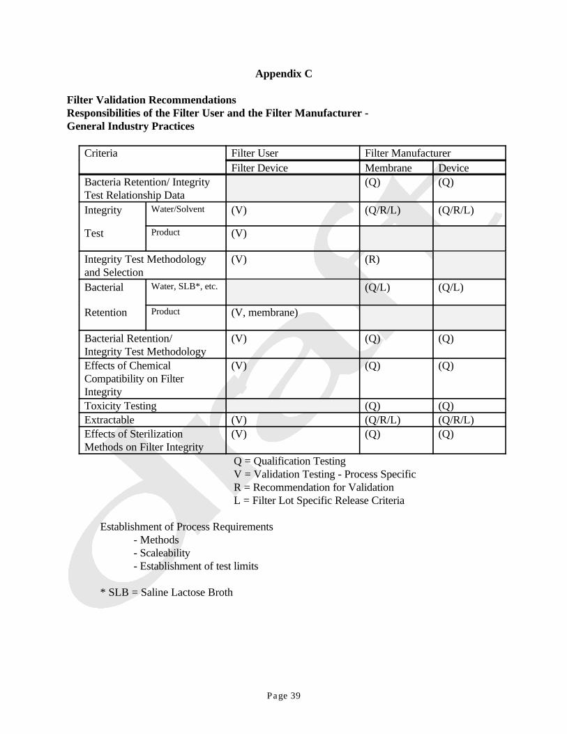
Page 39
Appendix C
Filter Validation Recommendations Responsibilities of the Filter User and the Filter Manufacturer - General Industry Practices
Criteria Filter User Filter ManufacturerFilter Device Membrane Device
Bacteria Retention/ Integrity (Q) (Q)Test Relationship DataIntegrity (V) (Q/R/L) (Q/R/L)Water/Solvent
Test (V)Product
Integrity Test Methodology (V) (R)and SelectionBacterial (Q/L) (Q/L)Water, SLB*, etc.
Retention (V, membrane)Product
Bacterial Retention/ (V) (Q) (Q)Integrity Test MethodologyEffects of Chemical (V) (Q) (Q)Compatibility on FilterIntegrityToxicity Testing (Q) (Q)Extractable (V) (Q/R/L) (Q/R/L)Effects of Sterilization (V) (Q) (Q)Methods on Filter Integrity
Q = Qualification TestingV = Validation Testing - Process SpecificR = Recommendation for ValidationL = Filter Lot Specific Release Criteria
Establishment of Process Requirements- Methods- Scaleability- Establishment of test limits
* SLB = Saline Lactose Broth
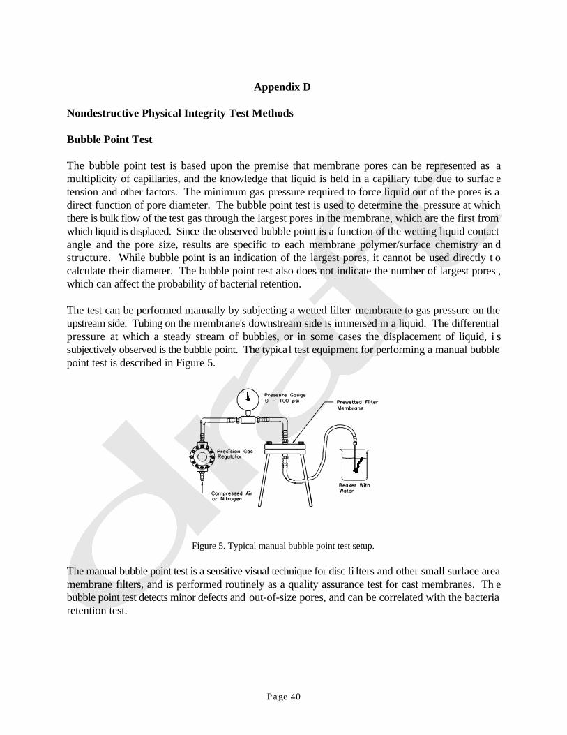
Page 40
Appendix D
Nondestructive Physical Integrity Test Methods
Bubble Point Test
The bubble point test is based upon the premise that membrane pores can be represented as amultiplicity of capillaries, and the knowledge that liquid is held in a capillary tube due to surfac etension and other factors. The minimum gas pressure required to force liquid out of the pores is adirect function of pore diameter. The bubble point test is used to determine the pressure at whichthere is bulk flow of the test gas through the largest pores in the membrane, which are the first fromwhich liquid is displaced. Since the observed bubble point is a function of the wetting liquid contactangle and the pore size, results are specific to each membrane polymer/surface chemistry an dstructure. While bubble point is an indication of the largest pores, it cannot be used directly t ocalculate their diameter. The bubble point test also does not indicate the number of largest pores ,which can affect the probability of bacterial retention.
The test can be performed manually by subjecting a wetted filter membrane to gas pressure on theupstream side. Tubing on the membrane's downstream side is immersed in a liquid. The differentialpressure at which a steady stream of bubbles, or in some cases the displacement of liquid, i ssubjectively observed is the bubble point. The typical test equipment for performing a manual bubblepoint test is described in Figure 5.
Figure 5. Typical manual bubble point test setup.
The manual bubble point test is a sensitive visual technique for disc fi lters and other small surface areamembrane filters, and is performed routinely as a quality assurance test for cast membranes. Th ebubble point test detects minor defects and out-of-size pores, and can be correlated with the bacteriaretention test.

Page 41
Points to Consider when Performing the Manual Bubble Point Test:
- Pressure should be increased slowly in a step-wise manner. - Allow pressure to stabilize at each step in the pressure increase. The true bubble point value
may be overshot if pressure is increased too rapidly. The test cannot be repeated withou trewetting the membrane.
- Minimize downstream connections and avoid kinking the downstream tubing. - Check for leaks in the system. - Clearly define the bubble point as bulk air flow. The most common error is misidentifyin g
bubbles that are not the result of bulk flow. Some bubbles will result as a result of diffusionacross the wetted membrane. Free flowing air is the indication, not the first bubble.
- Manually performed bubble point test determination can be subjectively different from oneoperator to another, therefore, operators should be properly trained to conduct the test andto interpret test results.
- Keep upstream volume to a minimum. With extremely high upstream volumes, longe rstabilization between pressure increases may be required.
- Maintain the temperature within the required range.
Advantages- quick (short stabilization time)- directly related to the membrane pore size - easy to perform manually, for small area filters by a trained operator- effective for filters with low membrane surface areas
Limitations- Sensitivity is limited for large membrane area systems when test is conducted manually.- Manual methods may confuse diffusive flow below the bubble point with the actual bubblepoint.- Manual testing requires downstream, sterile side manipulations.
Automated integrity test units determine the bubble point using incremental pressure hold tests o rdirect mass flow measurements. The pressure hold tests are performed at increasing pressures, withthe bubble point identified as some point where pressure decays become non-linear, based on a nalgorithm specific to each instrument manufacturer.
Note: Filters may plug during processing. As filter membranes begin to plug, larger pores may beblocked, which can increase the bubble point. This increase should not be evaluated as achange in the filter cartridge's integrity. Should the integrity of the filter be lost durin gprocessing, a decrease in bubble point would result. (Theoretically, if a filter is completelyblocked with particles, there would be no achievable bubble point value.) The sam ephenomenon similarly would decrease diffusive flow (forward flow). This emphasizes th eimportance of the pre-use integrity test.
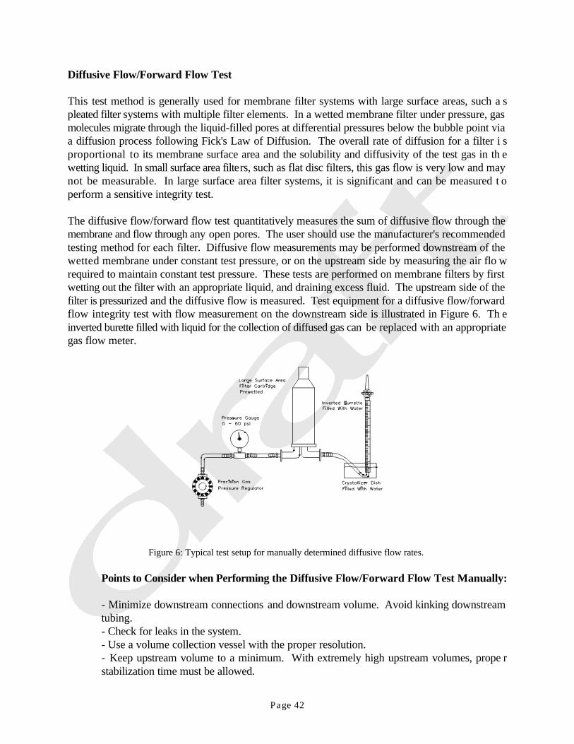
Page 42
Diffusive Flow/Forward Flow Test
This test method is generally used for membrane filter systems with large surface areas, such a spleated filter systems with multiple filter elements. In a wetted membrane filter under pressure, gasmolecules migrate through the liquid-filled pores at differential pressures below the bubble point viaa diffusion process following Fick's Law of Diffusion. The overall rate of diffusion for a filter i sproportional to its membrane surface area and the solubility and diffusivity of the test gas in th ewetting liquid. In small surface area filters, such as flat disc filters, this gas flow is very low and maynot be measurable. In large surface area filter systems, it is significant and can be measured t operform a sensitive integrity test.
The diffusive flow/forward flow test quantitatively measures the sum of diffusive flow through themembrane and flow through any open pores. The user should use the manufacturer's recommendedtesting method for each filter. Diffusive flow measurements may be performed downstream of thewetted membrane under constant test pressure, or on the upstream side by measuring the air flo wrequired to maintain constant test pressure. These tests are performed on membrane filters by firstwetting out the filter with an appropriate liquid, and draining excess fluid. The upstream side of thefilter is pressurized and the diffusive flow is measured. Test equipment for a diffusive flow/forwardflow integrity test with flow measurement on the downstream side is illustrated in Figure 6. Th einverted burette filled with liquid for the collection of diffused gas can be replaced with an appropriategas flow meter.
Figure 6: Typical test setup for manually determined diffusive flow rates.
Points to Consider when Performing the Diffusive Flow/Forward Flow Test Manually:
- Minimize downstream connections and downstream volume. Avoid kinking downstreamtubing.- Check for leaks in the system.- Use a volume collection vessel with the proper resolution.- Keep upstream volume to a minimum. With extremely high upstream volumes, prope rstabilization time must be allowed.

Page 43
- Maintain a stable testing temperature throughout the testing period.- Allow sufficient equilibration time after pressurizing the system.
Advantages- Increased sensitivity for large membrane surface area systems when test is conducte dmanually.- Objective, quantitative measure of gas flow.- Does not require downstream manipulation when performed in upstream test mode.- Does not require upstream volume determination.- Correlatable to bacterial retention.
Limitations- More sensitive to temperature fluctuations than bubble point test.- Requires downstream manipulations when performed in downstream mode.
Pressure Hold/Pressure Decay Test
The pressure hold (or pressure decay) test is an indirect method of upstream diffusive flow/forwardflow testing. In this method, the filter housing is pressurized to a predetermined setting, then isolatedfrom the pressure source. Gas diffusion across the membrane is quantitatively measured as a decayin pressure over a specific period of time. The allowable pressure drop is unique to a given filter andsystem and is calculated by taking into account the diffusive flow s pecification at a given pressure andconstant temperature, the upstream system volume and the duration of the test. This test has beenindirectly correlated to bacterial retention.
The pressure hold/decay test measures the diffusive gas (typically air or nitrogen) flow through allthe wetted pores, and the bulk gas flow through larger nonwetted pores, when applying apredetermined gas pressure to a wetted filter. Pressure decay on the upstream side is then measured,after isolating the incoming gas supply. The pressure decay is a function of the gas flow through thefilter. If the pressure decay is below the maximum allowable value, the physical integrity test passes.If the decay and concomitant pressure drop exceed the correlated maximum allowable value, the testfails.
Upstream integrity tests are particularly useful in critical fluid applications since they can b eperformed without compromising the sterility of the downstream system. The pressure hold/decaytest will confirm the integrity of the entire assembly, including housing seals. Therefore, failur eanalysis for lack of seal integrity is required prior to reaching the conclusion that the filter elementitself is not integral.
In performing the pressure hold/decay test, the physical conditions must be held constant, as the testis affected by interactions of temperature, system volume and filter area. The pressure hold/decaytest equipment is illustrated in Figure 7. This test commonly is performed preprocess, post -sterilization of the filter assembly, and again after sterilizing filtration.
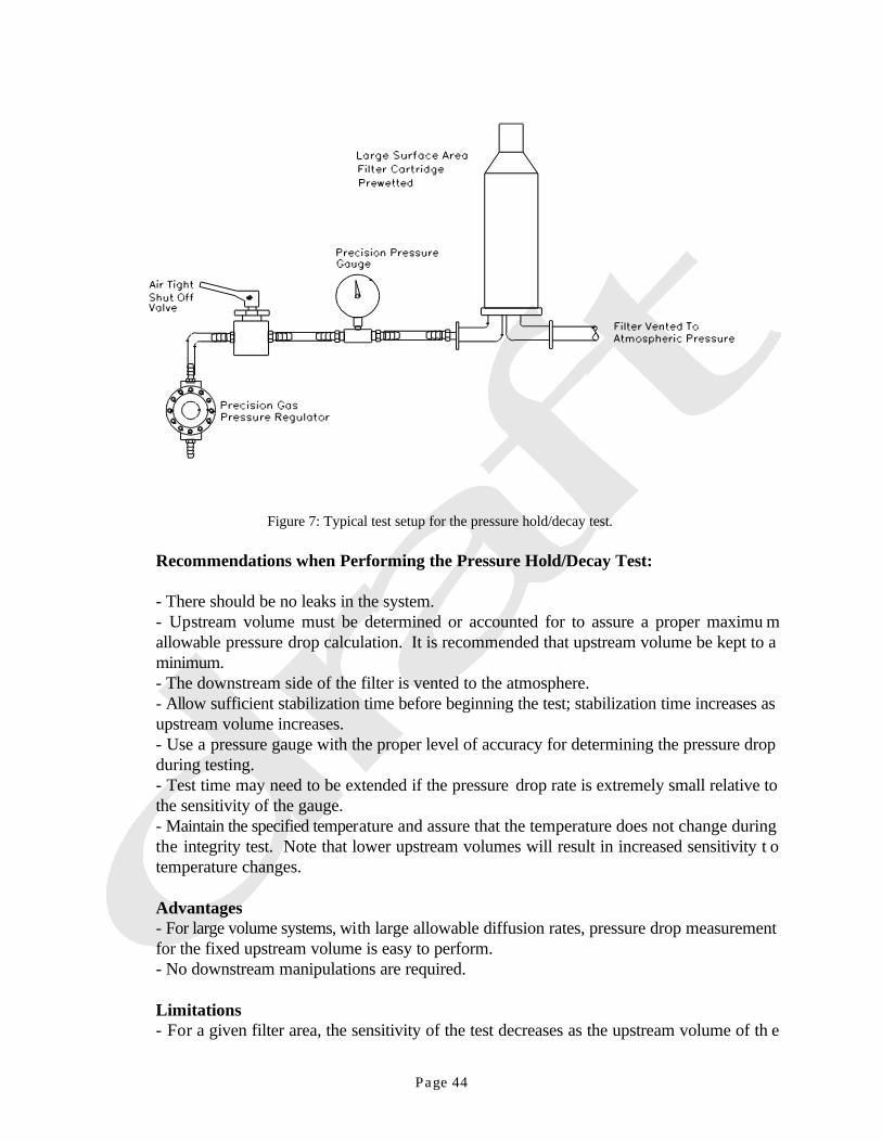
Page 44
Figure 7: Typical test setup for the pressure hold/decay test.
Recommendations when Performing the Pressure Hold/Decay Test:
- There should be no leaks in the system.- Upstream volume must be determined or accounted for to assure a proper maximu mallowable pressure drop calculation. It is recommended that upstream volume be kept to aminimum.- The downstream side of the filter is vented to the atmosphere.- Allow sufficient stabilization time before beginning the test; stabilization time increases asupstream volume increases.- Use a pressure gauge with the proper level of accuracy for determining the pressure dropduring testing.- Test time may need to be extended if the pressure drop rate is extremely small relative tothe sensitivity of the gauge.- Maintain the specified temperature and assure that the temperature does not change duringthe integrity test. Note that lower upstream volumes will result in increased sensitivity t otemperature changes.
Advantages- For large volume systems, with large allowable diffusion rates, pressure drop measurementfor the fixed upstream volume is easy to perform.- No downstream manipulations are required.
Limitations- For a given filter area, the sensitivity of the test decreases as the upstream volume of th e

Vs (M/ S)AF
D(p2 p1)k
HcL
p2Vup NRT
dp2
dtVup
dNdt
RT
Page 45
system is increased.- The resolution of the test is limited by the resolution of the pressure sensor used.- Process conditions for the test, including temperature and gas used for pressurization, mustbe defined for the issuance of integrity test values. The upstream sys tem also must be defined.This would include the housing used and the number of cartr idges in it, as well as the volume.
Correlation Between Pressure Hold/Decay and Diffusive Flow/Forward Flow
Diffusive flow prior to the initiation of any bulk flow through the first opened pore can be expressedby the following equation, derived from Fick’s Law and Henry’s Law.
(Equation 10)
The measured diffusive flow, resulting from a specified differential pressure, can be related to th emicrobial retentive capability of a filter membrane.
The relationship between this diffusive flow, measured in the nondestructive Pressure Hold/DecayTest, and the destructive microbial challenge test is the objective of the validation for each filte rmedium and each filter configuration.
Equation 10 shows that diffusive flow is proportional to the difference between the test pressure andatmospheric pressure. Since the pressure in the upstream volume decreases, due to the effluen tdiffusive flow, the flow also decreases.
From the ideal gas equation
(Equation 11a)
the change of state per time dt can be derived:
(Equation 11b)

Vs sdNdt
dp2
dt
Vup
RT
MAFD(p2 p1)k
LHC
1p2 p1
( dp2)RTVup
MAFD
LHc
kdt
p2I p2II (p2I pI)(1 exp[ RTVup
MAFD
LHc
k(tII tI)])
p2I p2II (p2I pI)(1 exp[(tII tI)
Vup
Vsps
p2I pI)])
Page 46
With
(Equation 12)
and equations 10 and 11b can be written as:
(Equation 13a)
Hence,
(Equation 13b)
and carrying out the integration between limits and simplifying yields the result:
(Equation 13c)
To obtain an equation for the pressure decay (as a function of volume flow in the standard state) ,introducing equation 10 in 13c and using p = RT/M yields:S S
(Equation 14)
Measurements of pressure and time are necessary for the determination of Vs because the retentivecapability of the filter membrane is related to the flow Vs, as shown in Equation 14. Additionally, theupstream volume must be known and the temperature in the upstream volume must be constant.
Nomenclature for Symbols Used in Equations 10-14
A = area of the filterF
D = diffusion constant for gas/liquid systemHc = Henry’s Law coefficient

Page 47
k = membrane specific correction factorL = length of diffusion pathN = molesM = molar massp = atmospheric pressure1
p = upstream pressure2
p - p = differential pressure 2 1
P = pressure at t2I I
P = pressure at t2II II
p -p = pressure decay2I 2II
p - p = entered test pressure2I I
R = ideal gas constantT = temperaturet -t = entered test timeII I
V = upstream volumeup
V = standard volume flows
= density of gas in the standard states

Page 48
BIBLIOGRAPHY
1. Accomazzo, M. A. and D. C. Grant, "Mechanisms and Devices for Filtration of Critica lProcess Gasses," Fluid Filtration: Gas, Volume 1, ASTM STP 975, R. R. Raber, ed. ,American Society for Testing and Materials, Philadelphia, PA, 402-420 (1986).
2. P. Aicholtz, R. Wilkins and R. Gabler, "Sterile Filtration Under Conditions of High Pressureand Bacterial Challenge Levels," J. Parent. Sci. Tech., 41, 117-120 (1987).
3. ASTM Proposed Tentative Test Method, "Test for Determination of Characteristics o fMembrane Filters for Use in Aerospace Liquid," June 1, 1965.
4. American Society for Testing and Materials (ASTM), "Standard Test Method fo rDetermining Bacterial Retention of Membrane Filters Utilized for Liquid Filtration," ASTMStandard F838-83, ASTM, Philadelphia, PA (1983).
5. American Society for Testing and Materials (ASTM), "Standard Test Method for RetentionCharacteristics of 0.40 to 0.45 m Membrane Filters used in Routine Filtration Proceduresfor the Evaluation of Microbiological Water Quality," ASTM Standard D3863-80 ,Philadelphia, PA (1980).
6. Andersen, et al., Appl. & Environ. Micro., 50, 1341-1348 (1985).7. H. Arahna and J. Meeker, "Microbial Retention Characteristics of 0.2 m-rated Nylon
Membrane Filters during Filtration of High Viscosity Fluids at High Differential Pressure andVaried Temperatures," PDA J. Pharm. Sci. Technol., 49, 67-76 (1995).
8. F. W. Bowman and S. Holdowsky, Antibiol. Chemotherapy, 8, 508 (1960).9. F. W. Bowman, J. Pharm. Sci., 55, 818 (1966).10. F. Bowman, M. P. Calhoun and M. White, "Microbiological Methods for Quality Control of
Membrane Filters," J. Pharm. Sci., 56, 222 (1967).11. N. Brooks, "V.A. Synopsis of the PDA Panel on Filter Validation," J. Parent. Drug Assoc.,
5, 280-282 (1979).12. J. Carter, "Evaluation of Recovery Filters for Use in Bacterial Retention Testing o f
Sterilizing-Grade Filters," PDA J. Pharm. Sci. Technol., 50, 147-163 (1996).13. J. C. Cole and W. A. Pauli, "Field Experiences in Testing Membrane Filter Integrity by the
Forward Flow Test Method," Bull. Parenteral Drug Assoc., 29, 296-304 (1975).14. C. Desaulniers and T. Fey, "The Product Bubble-Point Ratio and Its Use in Filter Integrity
Testing," Pharmaceutical Technology, 14, 10, 42-52 (1990).15. A. Dileo, R. Levy and T. Leahy, "Sterilization Technology: New Development in Steril e
Filtration: Achieving True Sterility," Proceedings of the PDA/PMA Sterilization Conference,Washington, p. 171 (1990).
16. Erbe, F., Kolloid A., 63, 277 (1933).17. FDA, "Guideline on Sterile Drug Products Produced by Aseptic Processing," Center fo r
Drugs and Biologics, Rockville, MD, June, 1987.18. D. C. Grant, B. Liu, W. G. Fisher and R. A. Bowling, "Partic le Capture Mechanisms in Gases
and Liquids: An Analysis of Operative Mechanisms," Proceedings - Insti tute of EnvironmentalSciences (1988).
19. E. A. Hardwidge, S. S. Chrai, F. W. Dawson, C. Radowitz, T. H. Mel tzer and W. P. Zeronsa,"Validation of Filtration Processes Used for Sterilization of Liquids," J. Parent. Sci. Tech.,36, 37-43 (1984).
20. F. Hofmann, "Integrity Testing of Microfiltration Membranes," J. Parent. Sci. Tech., 38, 148-159 (1984).
Page 49
21. S. Holdowsky, Antibiol. Chemotherapy, 2, 19 (1957).22. G. Howard and R. Duberstein, "A Case of Penetration of 0.2- m Rated Membrane Filters by
Bacteria," J. Parent. Drug Assoc., 34, 93-102 (1980).23. R. Jaenchen, S. Cole and G. Howard, "A Review of Principles and Procedures for Validation
of Liquid Sterilising Filters," Proceedings of the PDA Second International Congress, Basel,pp. 34-39 (1994).
24. G. Jordan, "Micro-Filtration in the Production of Parenterals," Bull. Parenteral Drug Assoc.,13, 21-24 (1959).
25. R. E. Kesting, L. K. Cunningham, M. C. Morrison and J. F. Ditter, "Nylon Microfiltratio nMembranes: State of the Art," J. Parent. Sci. Tech., 37, 97-104 (1983).
26. S. J. Kovary, J. P. Agalloco and B. M. Gordon, "Validation of the Steam-In-Plac eSterilization of Disc Filter Housings and Membranes," J. Parent. Sci. Tech., 37, 55-64(1983).
27. T. J. Leahy and M. Sullivan, "Validation of Bacterial Retention Capabilities of Membran eFilters," Pharmaceutical Technology, Nov., pp. 65-75 (1978).
28. J. Levchuk, "Good Validation Practices: FDA Issues," PDA J. Pharm. Sci. Technol., 48, 221-223 (1994).
29. R. C. Lukaszewicz, P. R. Johnston and T. H. Meltzer, "Prefilters/Final Filters: A Matter ofParticle/Pore Size-Distributions," J. Parent. Sci. Tech., 35, 40-47 (1981).
30. R. C. Lukaszewicz and T. H. Meltzer, "Concerning Filter Validation," J. Parent. DrugAssoc., 33, 187-194 (1979).
31. R. C. Lukaszewicz and T. H. Meltzer, "A Cooperative Address to Current Filter Problems,"J. Parent. Drug Assoc., 33, 246-249 (1979).
32. R. C. Lukaszewicz and T. H. Meltzer, "On the Structural Compatibilities of Membran eFilters," J. Parent. Drug Assoc., 34, 463-472 (1980).
33. W. D. MacDonald, C. A. Pelletier and D. L. Gasper, "Practical Methods for the Microbia lValidation of Sterilizing-Grade Filters Used In Aseptic Processing," J. Parent. Sci. Tech., 43,268-270 (1989).
34. J. C. Marshall and T. H. Meltzer, "Certain Porosity Aspects of Membrane Filters: Their Pore-Distributions and Anisotropy," Bull. Parenteral Drug Assoc., 30, 214-225 (1976).
35. C. B. McLaughlin, "The Sterilizing Effectiveness of Different Grade Seitz Filter Pads," Bull.Parenteral Drug Assoc., 6, 24-27 (1952).
36. J. T. Meeker, E. W. Hickey, J. M. Martin, and G. Howard, Jr., "A Quantitative Method forChallenging 0.1 m Rated Filters with A. Laidlawii," BioPharm, March (1988).
37. T. H. Meltzer and T. R. Meyers, "The Bubble Point in Membrane Characterization," Bull.Parenteral Drug Assoc., 25, 165-174 (1971).
38. Meltzer, Theodore H., ed., Filtration in the Pharmaceutical Industry, Marcel Dekker, Inc. ,New York, 1987.
39. T. H, Meltzer, "The Insufficiency of Single Point Diffusive Air Flow Integrity Testing," J.Parent. Sci. Tech., 46, 19-21 (1992).
40. T. H. Meltzer, "Some Observations Concerning Filter Validations," Proceedings of the PDASecond International Congress, Basel, pp. 146-156 (1993).
41. T. H. Meltzer, "The Significance of Sieve-Retention to the Filter Validation Process," PDAJ. Pharm. Sci. Technol., 49, 188-191 (1995).
42. R. A. Nash, B. E. Haeger, J. T. Powers and G. R. Personeus, "An Evaluation of MembraneFilters for Sterile Processing," Bull. Parenteral Drug Assoc., 21, 165-183 (1967).

Page 50
43. W. P. Olson, R. O. Briggs, C. M. Garanchon, M. J. Ouellet, E. A. Graf and D. G. Luckhurst,"Aqueous Filter Extractables: Detection and Elution from Process Filters," J. Parent. DrugAssoc., 34, 254-267 (1980).
44. W. P. Olson, E. D. Martinez and C. R. Kern, "Diffusion and Bubble Point Testing o fMicroporous Cartridge Filters: Preliminary Results at Production Facilities," J. Parent. Sci.Tech., 35, 218-222 (1981).
45. W. P. Olson, L. A. Gatlin and C. R. Kern, "Diffusion and Bubble Point Testing o fMicroporous Cartridge Filters: Electromechanical Methods," J. Parent. Sci. Tech., 37, 117-124 (1983).
46. M. Osumi, N. Yamada and M. Toya, "Bacterial Retention Mechanisms of Membrane Filters,"PDA J. Pharm. Sci. Technol., 50, 30-34 (1996).
47. D. B. Pall, "Quality Control of Absolute Bacteria Removal Filters," Bull. Parenteral DrugAssoc., 29, 392-204 (1975).
48. D. B. Pall and E. A. Kirnbauer, "Bacteria removal prediction in membrane filters," Presentedat 52nd Colloid and Surface Science Symposium, Univ. of Tenn., Knoxville, June 12, 1978.
49. J. M. Price and W. A. Pauli, "Utilization of New Integrity Test for Membrane Filte rCartridges," Bull. Parenteral Drug Assoc., 30, 45-48 (1976).
50. O. W. Reif, P. Sölkner and J. Rupp, "Analysis and Evaluation of Filter Cartridge Extractablesfor Validation in Pharmaceutical Downstream Processing," PDA J. Pharm. Sci. Technol., 50,399-410 (1996).
51. A. R. Reti, "An Assessment of Test Criteria for Evaluation the Performance and Integrity ofSterilizing Filters," Bull. Parenteral Drug Assoc., 31, 187-14 (1977).
52. A. R. Reti and T. J. Leahy, "Validation of Bacterially Retentive Filters by Bacterial PassageTesting," J. Parent. Drug Assoc., 33, 257-272 (1979).
53. H. L. Ritter and L.C. Drake, Ind. Eng. Chem., Anal. Ed., 17, 782 (1945).54. J. P. Robinson, "The Great Filter Rating Debate (Editorial)," J. Parent. Sci. Tech., 38, 47
(1984).55. K. Roche and R. V. Levy, "Methods Used to Validate Microporous Membranes for th e
Removal of Mycoplasma," BioPharm, 5, 22-33 (1992).56. T. C. Sauer, Society of Automotive Engineers, Fuel Filter Test Methods, Jan. 1961, p. 1
(1961).57. C. P. Schaufus, "High Volume Process Filtration with the New Millipore ‘Microweb’ Filter,"
Bull. Parenteral Drug Assoc., 11, 21-24 (1957).58. C. P. Schaufus, "Further Developments in Millipore Sterile Filtration Techniques," Bull.
Parenteral Drug Assoc., 16, 1-5 (1962).59. K. S. Sechovec, "Validation of an Automated Filter Integrity Tester for Use in Bubble Point
Testing," J. Parent. Sci. Tech., 43, 23-26 (1989).60. G. B. Tanny, D. K. Strong, W. G. Presswood and T. H. Meltzer, "Adsorptive Retention of
Pseudomonas diminuta by Membrane Filters," J. Parent. Drug Assoc., 33, 40-51 (1979).61. A. E. Tiesler, "Sterile Filtering, Filling and Sealing," Bull. Parenteral Drug Assoc., 2, 12-17
(1948).62. B. Trasen, "Non-Destructive Tests for Bacterial Retentive Filters," J. Parent. Drug. Assoc.,
33, 273-279 (1979).63. P. J. Waibel, M. Jornitz and T. H. Meltzer, "Diffusive Airflow Integrity Testing," PDA J.
Pharm. Sci. Technol., 50, 311-316 (1996).64. K. H. Wallhäusser, "Is The Removal of Microorganisms by Filtration Really a Sterilization

Page 51
Method?," J. Parent. Drug Assoc., 33, 156-170 (1979).65. C. H. Zierdt, "Unexpected Adherence of Bacteria, Blood Cells and other Particles to Large
Porosity Membrane Filters," Abstracts of The American Society for Microbiologists, 78 th
Annual Convention, Las Vegas, Article Q-43, p. 10 (1978).