paying for high speed networking services
TRANSCRIPT
PAYING FOR HIGH SPEED NETWORKING
SERVICES
by
ALBERTUS VAN NIEKERK
submitted in partial fulfillment of the requirements for the degree of
MASTER OF SCIENCE
in the subject
COMPUTER SCIENCE
at the
UNIVERSITY OF SOUTH AFRICA
SUPERVISOR: DR WB SMUTS
JANUARY 1997
Statement
I declare that PAYING FOR HIGH SPEED NETWORKING SERVICES is my own work and
that all the sources that I have used or quoted have been indicated and acknowledged by
means of complete references.
(A van Niekerk)
\\\\\\\\\\\~\ 0001101217
Abstract
The idea of a free network is a myth of the past. Networking costs are expected to remain a
burden to future IT budgets, no doubt raising questions regarding the payment of such
services.
Users do not normally pay to use local area networks, as companies tend to own their LANs.
However, when wide area or international networks are considered, the situation is different.
It is argued that in these cases the invoicing and payment system should be integral to the
network's communication protocol. This implies changes to the networking protocol (to handle
invoicing) as well as a new look at customary ideas of representing currency (to handle
payment).
In this dissertation, an invoicing and payment scheme that uses electronic cash and is
implemented as part of the basic ATM protocols is discussed. The main advantages of this
scheme can be summarized as a low administrative overhead and user privacy.
Key Terms
Overview of High Speed Protocols; High Speed Networking; ATM Signaling; ATM Connection
Setup; ATM Protocols; Electronic Cash; Electronic Payment; Anonymous Payment; Network
Integrated Invoicing and Payment System; Evaluation of modified ATM Setup methods.
ii

Table of Contents
INTRODUCTION ........................................................................................................................ 1
1 .1 . BACKGROUND ................................................................................................................ 1
1.2. PROBLEM STATEMENT ................................................................................................... 2
1 .3. HYPOTHESIS .................................................................................................................. 3
1 .4. ASSUMPTIONS ............................................................................................................... 3
1.5. OBJECTIVES OF THIS RESEARCH ..................................................................................... 3
1 .6. SCOPE .......................................................................................................................... 3
1.7. METHODOLOGY .............................................................................................................. 4
1.8. RELEVANCE OF RESEARCH ............................................................................................. 4
1.9. SUMMARY AND ORGANIZATION OF THIS DOCUMENT ......................................................... 5
THE HIGH SPEED NETWORKING ENVIRONMENT ............................................................... 7
2.1. INTRODUCTION ............................................................................................................... 7
2.2. LEAVING THE LOW SPEED COMFORT ZONE ....................................................................... 7
2.3. HIGH SPEED NETWORKING IN VARIOUS ENVIRONMENTS .................................................... 9
2.4. NETWORKING PROTOCOLS ........................................................................................... 11
2.5. TCP/IP ........................................................................................................................ 11
2.6. HIGH SPEED NETWORKING DEVICES .............................................................................. 25
2.7. ACCOUNTING IN A HIGH SPEED NETWORKING ENVIRONMENT ........................................... 27
2.8. SUMMARY .................................................................................................................... 27
ATM PROTOCOLS .................................................................................................................. 29
3 .1 . INTRODUCTION ............................................................................................................. 29
3.2. DEFINING ATM ............................................................................................................ 29
3.3. ATM PROTOCOL DESCRIPTION ..................................................................................... 31
3.4. SETTING UP ATM CONNECTIONS .................................................................................. 43
3.5. SUMMARY .................................................................................................................... 54
ELECTRONIC PAYMENT ........................................................................................................ 55
4.1. INTRODUCTION ............................................................................................................. 55
4.2. BACKGROUND .............................................................................................................. 55
4.3. DEVELOPMENT HISTORY OF NETWORK BASED CASH ELECTRONIC PAYMENTS .................. 56
iii
4.4. WHAT IS PAYMENT? ...................................................................................................... 57
4.5. REQUIREMENTS OF A PAYMENT SYSTEM ........................................................................ 58
4.6. NON-ELECTRONIC PAYMENT TECHNIQUES ..................................................................... 58
4.7. ELECTRONIC PAYMENT TECHNIQUES ............................................................................. 60 '
4.8. HOW TO PAY FOR NETWORK USE .................................................................................. 62
4.9. OVERVIEW OF AN ECASH TRANSACTION ......................................................................... 62
4.10. How ECASH WORKS································································································· 64
4.11. THE ECASH PROTOCOL ............................................................................................. 72
4.12. THE ADVANTAGES AND DISADVANTAGES OF USING ECASH .......................................... 73
4.13. SUMMARY ................................................................................................................ 74
PROPOSED INVOICING/PAYMENT SCHEME ...................................................................... 76
5.1. INTRODUCTION ............................................................................................................. 76
5.2. THE PREFERRED PLATFORM FOR IMPLEMENTATION ........................................................ 76
5.3. THE PREFERRED LEVEL OF IMPLEMENTATION IN THE ATM PROTOCOL STACK .................. 78
5.4. THE SIMPLIFIED ACCOUNTING ENVIRONMENT ................................................................. 78
5.5. THE SIMPLIFIED ATM CONNECTION SETUP PROCESS ..................................................... 80
5.6. THE SIMPLIFIED ECASH PROTOCOL. ............................................................................... 81
5.7. COMBINING ATM AND ECASH PROTOCOLS INTO A SIMPLE IPS ........................................ 83
5.8. EXTENDING THE SIMPLIFIED IPS TO A SECURE SYSTEM .................................................. 83
5.9. SETUP FOR A SECURE IPS ............................................................................................ 83
5.10. ADDING COST AND INTERVAL DATA ............................................................................ 83
5.11. CONNECT FOR A SECURE IPS ................................................................................... 83
5.12. STATUS (PAYMENT) MESSAGES IN A SECURE IPS ....................................................... 83
5.13. SUMMARY ................................................................................................................ 83
EVALUATION .......................................................................................................................... 83
6.1. INTRODUCTION ............................................................................................................. 83
6.2. CHANGES TO THE ATM SIGNALING AND ROUTING PROTOCOLS ....................................... 83
6.3. SIMPLE IPS OVERHEAD DURING ATM CONNECTION SETUP ............................................ 83
6.4. OVERHEAD OF SECURE IPS DURING ATM CONNECTION SETUP ..................................... 83
6.5. OVERHEAD DURING DATA TRANSFER OF SIMPLE IPS ..................................................... 83
6.6. OVERHEAD DURING DATA TRANSFER OF SECURE IPS .................................................... 83
6.7. CONCLUSION REGARDING FEASIBILITY ........................................................................... 83
6.8. ADVANTAGES AND DISADVANTAGES OF THE IPS ............................................................ 83
6.9. SUMMARY .................................................................................................................... 83
CONCLUSION ......................................................................................................................... 83
7 .1. FEASIBILITY OF PROPOSED EXTENSION TO ATM ........................................................... 83
iv

7.2. OBJECTIVES REACHED ................................................................................................. 83
7.3. CONCLUSION ............................................................................................................... 83
v

FIG 1-1
FIG 1-2
FIG 2-1
FIG2-2
FIG 2-3
FIG 2-4
FIG 2-5
FIG 2-6
FIG 2-7
FIG 2-8
FIG 2-9
FIG 2-10
FIG 2-11
FIG 2-12
FIG 2- 13
FIG 3- 1
FIG 3- 2
FIG 3- 3
FIG 3- 4
FIG 3- 5
FIG 3- 6
FIG 3- 7
FIG 3- 8
FIG 3- 9
FIG3-10
FIG 3- 11
FIG 3- 12
FIG 3- 13
FIG 3- 14
FIG 3-15
FIG 3- 16
FIG 3- 17
FIG 4-1
List of Figures
PROCESSES FORMING A TRANSACTION ................................................................ 2
TRANSACTION PROCESSES INCLUDED IN SCOPE ................................................... 4
THE EFFECT OF CLIENT SERVER TECHNOLOGY ON BANDWIDTH ............................... .
TCP/IP PROTOCOL ARCHITECTURE ................................................................... 11
TCP/IP AND THE OSI MODEL ............................................................................ 12
FDDI AND THE OSI MODEL ............................................................................... 14
X.25 AND THE OSI MODEL················································································ 16
FRAME RELAY AND THE OSI MODEL. ................................................................. 17
ISDN AND THE OSI MODEL ............................................................................... 18
SMDS AND THE OSI MODEL. ............................................................................ 19
SONET AND THE OSI MODEL. .......................................................................... 21
ATM AND THE OSI MODEL. ............................................................................... 23
PROTOCOLS VS NETWORK TYPE ....................................................................... 24
COMBINATION OF PROTOCOLS ........................................................................... 25
NETWORK DEVICES AND THE OSI ...................................................................... 26
STM vs ATM ................................................................................................... 30
ATM ARCHITECTURE ......................................................................................... 32
ATM LAYER IN OPERATION ................................................................................ 33
VPI AND VCI .................................................................................................... 35
VPI TRANSLATION INSIDE AN ATM SWITCH ........................................................ 35
MULTIPLEXING IN AN ATM SWITCH .................................................................... 36
ATM HEADER ................................................................................................... 37
AAL 1 SAR FORMAT ........................................................................................ 40
AAL3/4 SAR FORMAT ...................................................................................... 40
AAL 3/4 CONVERGENCE FORMAT .................................................................... .41
AAL 5 SAR FORMAT ........................................................................................ 42
AAL 5 CONVERGENCE FORMAT ........................................................................ 42
ATM SAAL ...................................................................................................... 45
Q.2931 SIGNALING MESSAGE FORMAT ............................................................... 47
NSAP ADDRESS EXAMPLE ................................................................................ 48
NSAP ADDRESS FORMAT ................................................................................. 49
A TM CONNECTION SETUP ................................................................................. 53
THE ECASH WITHDRAWAL .................................................................................. 62
vi
FIG4-2
FIG4-3
FIG4-4
FIG 4-5
FIG4-6
FIG 5- 1
FIG 5- 2
FIG 5-3
FIG 5- 4
FIG 5- 5
FIG 5- 6
FIG 5- 7
FIG 5- 8
FIG 6-1
FIG 6- 2
AN ECASH PAYMENT .......................................................................................... 63
CONVERTING RSA EXPONENTS TO MONETARY VALUE ....................................... 68
HOW TO DEVALUATE ECASH .............................................................................. 69
CREATING IDENTITY STRINGS ............................................................................ 70
USING A SELECTOR STRING ............................................................................... 71
ARCHITECTURE OF IPS NODE ............................................................................ 77
ATM LAYERS IN USE AT DIFFERENT NODES ....................................................... 78
THE NETWORK ACCOUNTING ENVIRONMENT ....................................................... 79
MULTIPLE OWNERS AND NETWORKS IN AN ACCOUNTING ENVIRONMENT ............... 79
SIMPLIFIED NETWORK ACCOUNTING ENVIRONMENT ............................................. 80
SIMPLIFIED ATM CONNECTION SETUP ................................................................ 81
E-CASH PROTOCOL IN A NETWORK ACCOUNTING ENVIRONMENT .......................... 82
SEPARATE PAYMENT CONNECTIONS IN A SECURE IPS ......................................... 83
INFORMATION ELEMENT FORMAT ....................................................................... 83
PROCESSES AUTOMATED BY IPS ....................................................................... 83
vii
Terminology and Abbreviations
Terminology:
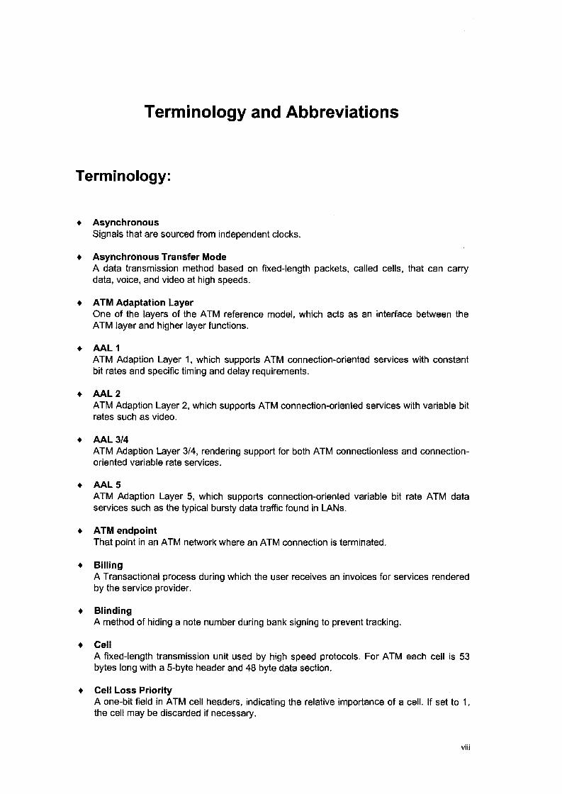
+ Asynchronous Signals that are sourced from independent clocks.
+ Asynchronous Transfer Mode A data transmission method based on fixed-length packets, called cells, that can carry data, voice, and video at high speeds.
+ ATM Adaptation Layer One of the layers of the ATM reference model, which acts as an interface between the ATM layer and higher layer functions.
+ AAL 1 ATM Adaption Layer 1, which supports ATM connection-oriented services with constant bit rates and specific timing and delay requirements.
+ AAL2 ATM Adaption Layer 2, which supports ATM connection-oriented services with variable bit rates such as video.
+ AAL 3/4 ATM Adaption Layer 3/4, rendering support for both ATM connectionless and connectionoriented variable rate services.
+ AAL5 ATM Adaption Layer 5, which supports connection-oriented variable bit rate ATM data services such as the typical bursty data traffic found in LANs.
+ ATM endpoint That point in an ATM network where an ATM connection is terminated.
+ Billing A Transactional process during which the user receives an invoices for services rendered by the service provider.
+ Blinding A method of hiding a note number during bank signing to prevent tracking.
+ Cell A fixed-length transmission unit used by high speed protocols. For ATM each cell is 53 bytes long with a 5-byte header and 48 byte data section.
+ Cell Loss Priority A one-bit field in ATM cell headers, indicating the relative importance of a cell. If set to 1, the cell may be discarded if necessary.
viii
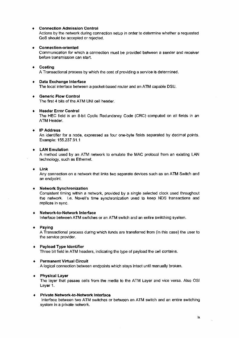
+ Connection Admission Control Actions by the network during connection setup in order to determine whether a requested QoS should be accepted or rejected.
+ Connection-oriented Communication for which a connection must be provided between a sender and receiver before transmission can start.
+ Costing A Transactional process by which the cost of providing a service is determined.
+ Data Exchange Interface The local interface between a packet-based router and an ATM capable DSU.
+ Generic Flow Control The first 4 bits of the ATM UNI cell header.
+ Header Error Control The HEC field is an 8-bit Cyclic Redundancy Code (CRC) computed on all fields in an ATM Header.
+ IPAddress An identifier for a node, expressed as four one-byte fields separated by decimal points. Example: 155.237.91.1
+ LAN Emulation A method used by an ATM network to emulate the MAC protocol from an existing LAN technology, such as Ethernet.
+ Link Any connection on a network that links two separate devices such as an ATM Switch and an endpoint.
+ Network Synchronization Consistent timing within a network, provided by a single selected clock used throughout the network. I.e. Novell's time synchronization used to keep NDS transactions and replicas in sync.
+ Network-to-Network Interface Interface between ATM switches or an ATM switch and an entire switching system.
+ Paying A Transactional process during which funds are transferred from (in this case) the user to the service provider.
+ Payload Type Identifier Three bit field in ATM headers, indicating the type of payload the cell contains.
+ Permanent Virtual Circuit A logical connection between endpoints which stays intact until manually broken.
+ Physical Layer The layer that passes cells from the media to the ATM Layer and vice versa. Also OSI Layer 1.
+ Private Network-to-Network Interface Interface between two ATM switches or between an ATM switch and an entire switching
system in a private network.
ix
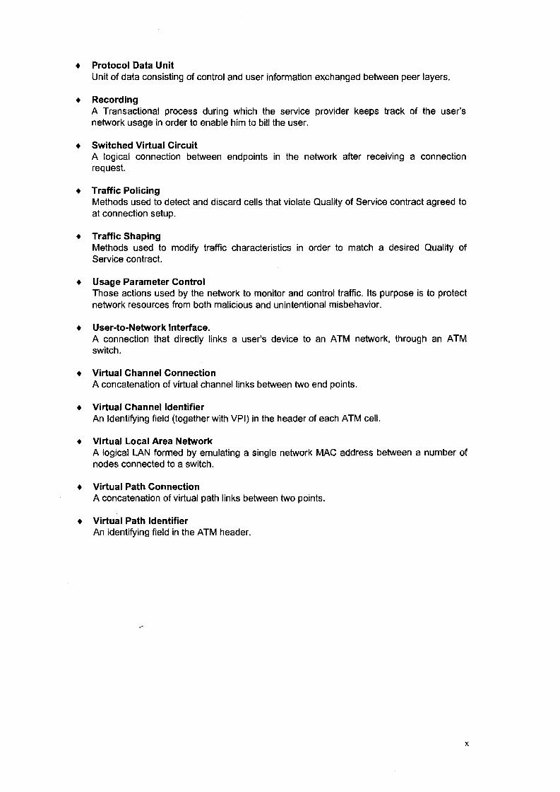
+ Protocol Data Unit Unit of data consisting of control and user information exchanged between peer layers.
+ Recording A Transactional process during which the service provider keeps track of the user's network usage in order to enable him to bill the user.
+ Switched Virtual Circuit A logical connection between endpoints in the network after receiving a connection request.
+ Traffic Policing Methods used to detect and discard cells that violate Quality of Service contract agreed to at connection setup.
+ Traffic Shaping Methods used to modify traffic characteristics in order to match a desired Quality of Service contract.
+ Usage Parameter Control Those actions used by the network to monitor and control traffic. Its purpose is to protect network resources from both malicious and unintentional misbehavior.
+ User-to-Network Interface. A connection that directly links a user's device to an ATM network, through an ATM switch.
+ Virtual Channel Connection A concatenation of virtual channel links between two end points.
+ Virtual Channel Identifier An Identifying field (together with VPI} in the header of each ATM cell.
+ Virtual Local Area Network A logical LAN formed by emulating a single network MAC address between a number of nodes connected to a switch.
+ Virtual Path Connection A concatenation of virtual path links between two points.
+ Virtual Path Identifier An identifying field in the A TM header.
x
Abbreviations:
• AAL
• ANSI
• ARP
• ATM
• B-ISDN
• CAC
• CBR
• CCITT
• CLP
• cs
• CRC
• ECash
• FCS
• FDDI
• GFC
• HEC
• HSNP
• IEEE
• IP
• IPX
• IPS
• ISDN
• ISO
• ITU
• LAN
A TM Adaptation Layer
American National Standards Institute
Address Resolution Protocol
Asynchronous Transfer Mode
Broadband Integrated Services Digital Network
Connection Admission Control
Constant Bit Rate
Consultative Committee on International Telephone and Telegraph (now ITU)
Cell Loss Priority
Convergence Sublayer
Cyclic Redundancy Code
Electronic Cash
Frame Check Sequence
Fiber Distributed Data Interface
Generic Flow Control
Header Error Control
High Speed Networking Protocol
Institute of Electrical and Electronics Engineers
Internet Protocol
Internet Packet Exchange
Invoice and Payment System
Integrated Services Digital Network
International Standards Organization
International Telecommunications Union (formerly CCITT)
Local Area Network
xi
• OSU
• MAC
• MAN
• MIB
• NOIS
• NNI
• OC-n
• 001
• OSI
+ POU
+ P-NNI
+ PTI
+ PVC
+ QoS
+ RIP
+ SAAL
+ SAR
+ SOH
+ SEAL
+ SNMP
+ SONET
+ SS
+ STM
+ SVC
+ TCP
+ TCP/IP
+ TOM
+ UNI
• vc
Digital Service Unit
Media Access Control
Metropolitan Area Network
Management Information Base
Network Driver Interface Specification
Network-to-Network Interface
Optical Carrier-n
Open Datalink Interface
Open Systems Interconnect
Protocol Data Unit
Private Network-to-Network Interface
Payload Type Identifier
Permanent Virtual Circuit
Quality of Service
Routing Information Protocol
Signaling ATM Adaptation Layer
Segmentation And Reassembly
Synchronous Digital Hierarchy
Simple and Efficient Adaptation Layer
Simple Network Management Protocol
Synchronous Optical Network
Switching System
Synchronous Transfer Mode
Switched Virtual Circuit
Transmission Control Protocol
Transmission Control Protocol/Internet Protocol
Time Division Multiplexing
User-to-Network Interface
Virtual Channel
xii
• vcc Virtual Channel Connection
• VCI Virtual Channel Identifier
• VLAN Virtual Local Area Network
• VP Virtual Path
• VPC Virtual Path Connection
• VPI Virtual Path Identifier
• WAN Wide Area Network
xiii
Chapter 1
Introduction
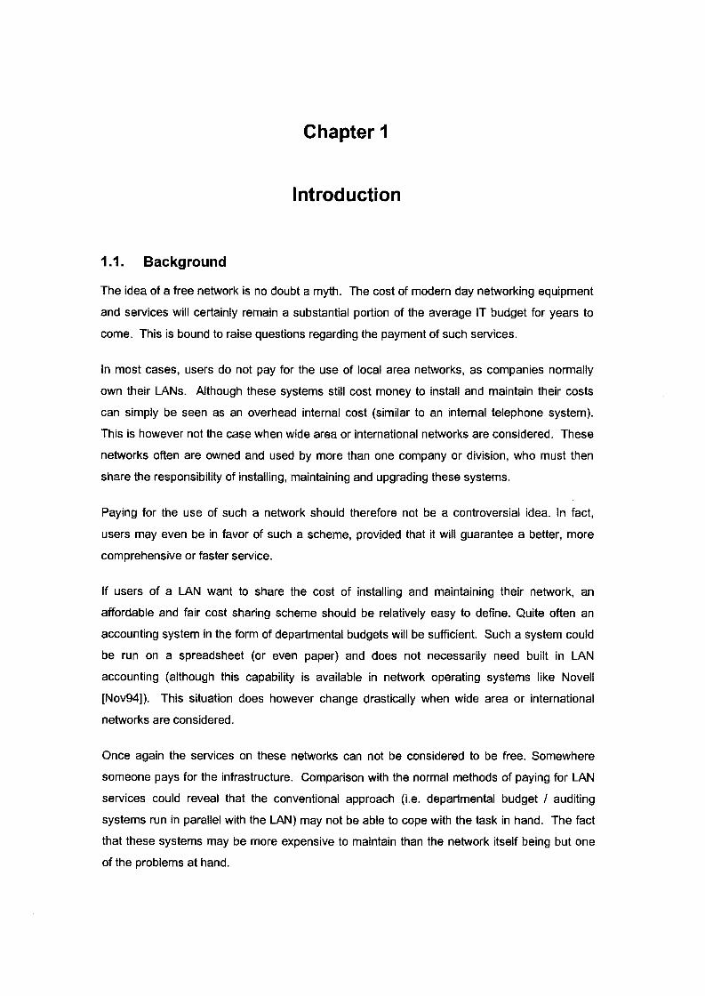
1.1. Background
The idea of a free network is no doubt a myth. The cost of modern day networking equipment
and services will certainly remain a substantial portion of the average IT budget for years to
come. This is bound to raise questions regarding the payment of such services.
In most cases, users do not pay for the use of local area networks, as companies normally
own their LANs. Although these systems still cost money to install and maintain their costs
can simply be seen as an overhead internal cost (similar to an internal telephone system).
This is however not the case when wide area or international networks are considered. These
networks often are owned and used by more than one company or division, who must then
share the responsibility of installing, maintaining and upgrading these systems.
Paying for the use of such a network should therefore not be a controversial idea. In fact,
users may even be in favor of such a scheme, provided that it will guarantee a better, more
comprehensive or faster service.
If users of a LAN want to share the cost of installing and maintaining their network, an
affordable and fair cost sharing scheme should be relatively easy to define. Quite often an
accounting system in the form of departmental budgets will be sufficient. Such a system could
be run on a spreadsheet (or even paper) and does not necessarily need built in LAN
accounting (although this capability is available in network operating systems like Novell
[Nov94]). This situation does however change drastically when wide area or international
networks are considered.
Once again the services on these networks can not be considered to be free. Somewhere
someone pays for the infrastructure. Comparison with the normal methods of paying for LAN
services could reveal that the conventional approach (i.e. departmental budget I auditing
systems run in parallel with the LAN) may not be able to cope with the task in hand. The fact
that these systems may be more expensive to maintain than the network itself being but one
of the problems at hand.
Chapter 1 : Introduction
The data communication and telecommunication fields have often in the past found each
other's solutions to common problems beneficial. However, prevailing methods of dealing with
these problems in the telecommunication community also seem to be overly expensive and
cumbersome.
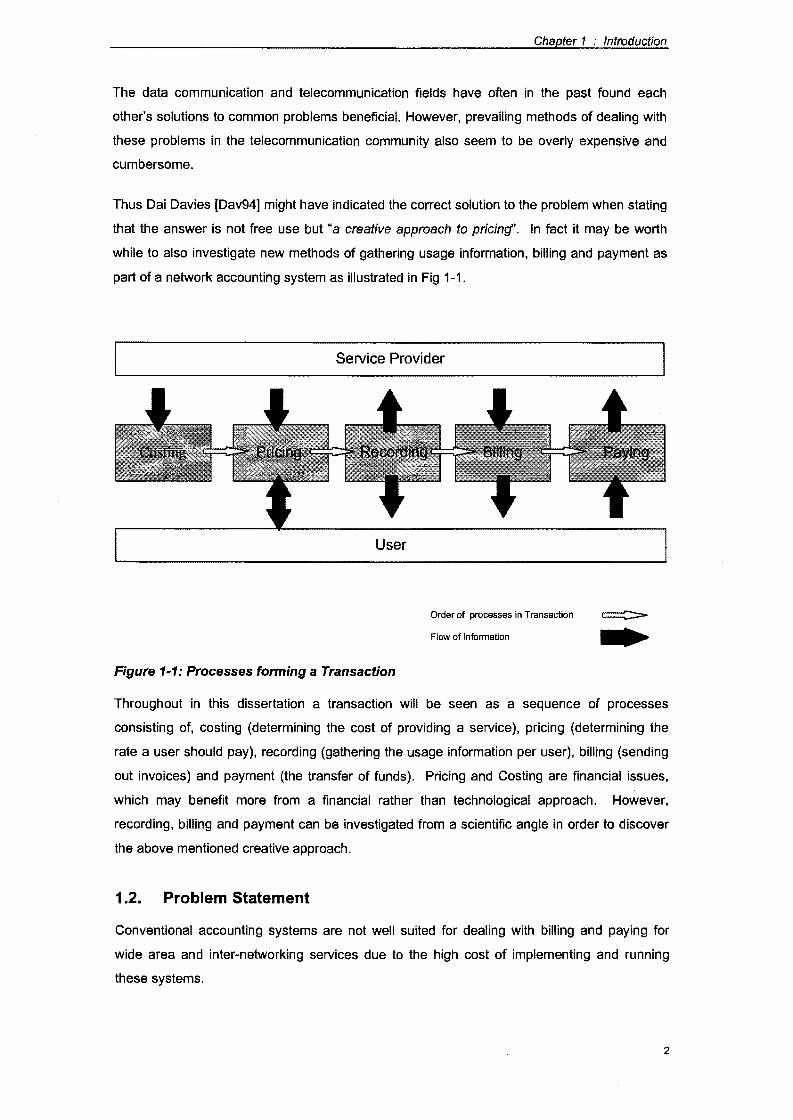
Thus Dai Davies [Dav94] might have indicated the correct solution to the problem when stating
that the answer is not free use but "a creative approach to pricing". In fact it may be worth
while to also investigate new methods of gathering usage information, billing and payment as
part of a network accounting system as illustrated in Fig 1-1.
Service Provider
User
Order of processes in Transaction
Flow of Information
Figure 1-1: Processes forming a Transaction
Throughout in this dissertation a transaction will be seen as a sequence of processes
consisting of, costing (determining the cost of providing a service), pricing (determining the
rate a user should pay), recording (gathering the usage information per user), billing (sending
out invoices) and payment (the transfer of funds). Pricing and Costing are financial issues,
which may benefit more from a financial rather than technological approach. However,
recording, billing and payment can be investigated from a scientific angle in order to discover
the above mentioned creative approach.
1.2. Problem Statement
Conventional accounting systems are not well suited for dealing with billing and paying for
wide area and inter-networking services due to the high cost of implementing and running
these systems.
2
Chapter 1 : Introduction
1.3. Hypothesis
The hypothesis is made that it is possible to implement a cost effective accounting system by
using a form of electronic cash and incorporating recording, billing and payment as an integral
part of the High Speed Networking Protocol.
1.4. Assumptions
In order to limit the scope of this dissertation, as well as to maintain the relevance of the
research done here, the following assumptions are made:
+ On future wide area and internetworks, bandwidth will still be a restricted and (to a
certain extent) scarce commodity.
+ The availability of video on demand, client server, voice-mail and fast processors will
increase the demand for bandwidth on future networks.
+ With the availability of the Internet and other information services it can be assumed
that traffic on future networks will no longer abide by the 80/20 rule stating that 80% of
traffic will stay local [Ser94].
+ It is preferable to handle the cost of a connection as just another characteristic of that
connection (to be controlled in a similar fashion as time delay is controlled}.
1.5. Objectives of this research
The objectives of this research include:
+ To understand ATM;
+ To understand electronic billing and ecash;
+ To propose an ATM-embedded billing and payment method;
+ To evaluate this method by means of computations.
1.6. Scope
In order to reach the above mentioned objectives, this study includes an overview of
transaction recording, billing and ecash payment techniques. The high speed networking
environment and current ATM protocols are also examined, after which an extension to ATM,
that includes billing and payment, is proposed and evaluated.
As Costing and Pricing are seen as processes that should rather be approached from a
financial point of view, they are specifically not included as part of this research. Regarding
the high speed networking protocols, the emphasis falls on ATM. The extension of electronic
3

Chapter 1 : Introduction
billing and payment techniques to protocols like Fast Ethernet and Frame Relay are not
considered to fall inside the scope of this research and as such, these protocols are not
discussed in depth.
Service Provider
I Costing j
User
Order of processes in Transaction
Flow of Information
Figure 1-2: Transaction Processes included in scope
With reference to Figure 1.1 the discussion can thus be seen to focus on implementing the
indicated processes (shaded parts in Figure 1.2) as an integral part of the ATM protocol.
1. 7. Methodology
In order to cover the above mentioned scope, this dissertation is approached as a theoretic
study of the fields mentioned above. To evaluate the proposed extension to the ATM protocol
a computational approach is used rather than simulation or a full implementation.
1.8. Relevance of Research
Dai Davies [Dav94] has pointed out that "There is no such thing as a free lnternef'. As stated
before, providing networking services currently costs money and in future it can be expected
that they will still do so. This means that someone will be paying for these networking services
and infrastructure.
Serjak [Ser94] points out that in an age where telecommuting is becoming a reality,
companies expect that their employees should be able to use network resources regardless of
the user's and the resource's location. This contributes to the breaking of what he calls the
4
Chapter 1 : Introduction
80/20 rule of networking. Yet, as stated in section 1.1, current methods of handling network
costs are much better suited to LAN's than to international/global networks.
Studies done by Parris, show that the Qualities of Service (QoS) available on high speed
networks are complex enough to justify a new look at pricing in integrated networks. He also
mentions that the correct approach to pricing may help to equalize the demand on networks
with definitive peaks in traffic. [PF92]
In an article by Smuts [Smu95], it is pointed out that free networks with the ability to reserve
certain services, coupled with a service guarantee and limited bandwidth (as assumed in 1.1 ),
may change the free-for-all principle to a free-for-a-few approach. Obviously the same goes
for a relative low fixed rate.
From the above it can be seen that:
+ Networking costs money and will still do so in future;
+ The current approaches (including built in LAN accounting systems) are not suited to
control increased WAN and inter-network traffic;
+ The use of a free-for-all, or a fixed rate accounting method is not suited to a high
speed networking protocol that provides reservation and service guarantees.
Thus, it can be concluded that it may be necessary to pay for certain types of network use in
future and that research regarding new methods of doing so is no doubt relevant.
1.9. Summary and Organization of this Document
This dissertation includes a theoretic overview, a proposal and an evaluation. It is organized
around three main topics, dealing with:
+ ATM;
+ billing and ecash and
+ the proposed combination of these two fields.
In chapter two the high speed networking environment is described, touching on subjects like
service guarantees and the motivation behind reservation and payment.
Chapter three gives a theoretical overview of ATM and chapter four a theoretical overview of
ecash. These chapters can be skipped by a reader who is familiar with these topics.
Chapter five discusses a proposed extension to the ATM protocol to include billing and
payment by ecash as part of the basic ATM protocol. Chapter six evaluates this scheme by
5

Chapter 1 : Introduction
means of computation, with chapter seven summarizing the research and drawing certain
conclusions regarding the viability of the proposed ATM extension based on this evaluation.
6
Chapter 2
The High Speed Networking Environment
2.1. Introduction
Shortly after the development of the 8086 PC, it was deemed that an average network speed
of 10 Mb/s is more than sufficient. As a matter of fact it was the author's experience that some
users preferred to keep their data on the LAN, because access to the server was much faster
than to their own PC's hard drive. This is, however, no longer the case, in fact, chances are
that with the advent of PC's like the 160Mhz Pentium, the 10 Mb/s Ethernet LAN has become
the bottleneck in the system.
Serjack [Ser94], points out that just about everything in the computing environment has
changed - except the network. He continues to indicate that it is necessary to move to
different LAN I WAN and Internet technologies, in order to render a worth while network
service. These and other problems in the networking environment lead to the development of
several high speed protocols and devices.
This chapter indicates, why high speed networking services should be considered necessary,
rather than preferable in the future IT industry. In section 2.3 a short overview of the current
technologies in various sizes of networks is given. The different protocols and devices
available for use in these networks are discussed in section 2.5 and 2.6. Finally it is shown
why ATM is considered to be the best technology on which to implement the accounting
system proposed in chapter six.
2.2. Leaving the low speed comfort zone
The current low speed networking technologies, having been matured during a number of
years of development can be seen as reasonably stable. On average the modern day
equipment using these protocols are quite advanced and reliable. No doubt the question can
then be asked, why change? The answer can be found in the following [Ser94] :
2.2.1. Downsizing
The IT industry is moving away from large mainframes towards client server
computing. This means that subroutine calls become network transactions. Figure 2-
Chapter 2 :The High Speed Networking Environment
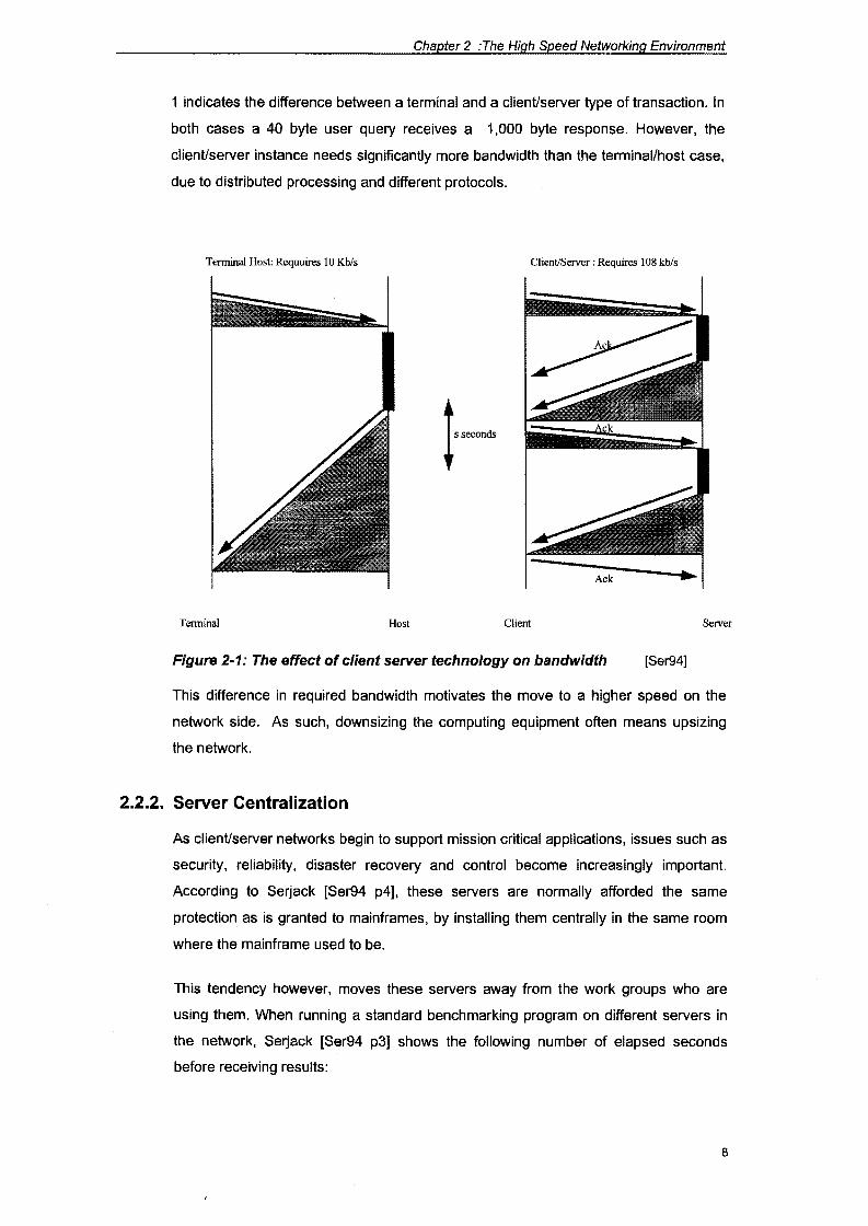
1 indicates the difference between a terminal and a client/server type of transaction. In
both cases a 40 byte user query receives a 1,000 byte response. However, the
client/server instance needs significantly more bandwidth than the terminal/host case,
due to distributed processing and different protocols.
Terminal Host: Requuires 10 Kb/s Client/Server : Requires 108 kb/s
Terminal Host Client Server
Figure 2-1: The effect of client server technology on bandwidth [Ser94]
This difference in required bandwidth motivates the move to a higher speed on the
network side. As such, downsizing the computing equipment often means upsizing
the network.
2.2.2. Server Centralization
As client/server networks begin to support mission critical applications, issues such as
security, reliability, disaster recovery and control become increasingly important.
According to Serjack [Ser94 p4], these servers are normally afforded the same
protection as is granted to mainframes, by installing them centrally in the same room
where the mainframe used to be.
This tendency however, moves these servers away from the work groups who are
using them. When running a standard benchmarking program on different servers in
the network, Serjack [Ser94 p3] shows the following number of elapsed seconds
before receiving results:
8
Chapter 2 :The High Speed Networking Environment
+ on a workgroup server : 1.1 seconds
+ on a server centralized in a data center on the same LAN : 1.6 seconds
+ on a server in a data center across the WAN : 8.6 seconds
Once again this means an increased required bandwidth due to an increase in
latency. Thus, this is another factor motivating the move towards high speed
networks.
2.2.3. What the user expects
Due to perceived speed of their new generation workstations, users have grown
accustomed to a certain reaction time from their PCs. However, at the same time the
nature of the average type of application run across the network is changing.
Applications like voice-mail, video conferencing and multimedia presentations are all
bandwidth hungry due to their size and time restrictions. Partridge [Par94 p226]
points out that some of today's networking protocols may be adapted to sustain
GigabiUsec speeds but that these protocols do not support performance guarantees
regarding delay and bandwidth, which are no doubt necessary in such an
environment. It should therefore be clear that the 10 Mb/s Ethernet or the 16 Mb/s
Token-Ring may not be sufficient any longer. No doubt the question will then arise,
what next?
2.3. High speed networking in various environments
2.3.1. LAN
In the LAN environment, the answer to what comes after 10 Mb!s Ethernet? at one
stage seemed to have varied between, Fast Ethernet and ATM. Advocates of both
points of view appeared to be smugly self assured that their point of view is correct.
However, the recent opinion seem to be more biased towards ATM, or an ATM I
Ethernet combination. (See [Lind93], [Axn93], [Ben94].)
The main advantage pointed out by those who prefer Fast Ethernet is that it will run on
a company's existing Ethernet technology (if they are already using CAT 5 UTP). Due
to its cost implications, this factor can therefore not be ignored. However, as is pointed
out by [Lind93], Ethernet has the disadvantage of still providing a limited bandwidth.
Except for it's scaleable bandwidth, ATM also does have another big point in it's favor;
it can run on both the LAN and the WAN environment. With the help of LAN
Emulation it can also, like Fast Ethernet, be tied into an existing Ethernet LAN. (I.e.
9
Chapter 2 :The High Speed Networking Environment
using switches with both ATM and Ethernet ports in order to replace only the hart of
an existing Ethernet LAN with ATM.)
2.3.2. WAN
With the above mentioned in mind, it may appear that that the future choice in the
WAN environment should also fall on ATM. In this case, Fast Ethernet is not really a
contender, but, FDDI and TCP/IP has already got a large share of the market.
However, the IT industry does seem to be getting ready for a move towards ATM.
(See [LAN96 p14] for a case study regarding migration from FDDI to ATM.)
In order to justify why we will consider ATM as the network protocol on which to
implement our proposed accounting system, it may be necessary to briefly examine
some of the other protocols in the high speed networking environment. As our
accounting system should be optimal in the WAN environment rather than for LANs
(see par 1.1) Fast Ethernet will not be discussed in more detail.
2.3.3. Intranet
lntranets can be seen as a relative new term developed by the industry. However it
refers to an idea that has been around for some time, that of using Internet
(specifically TCP/IP) technology on a LAN, or private WAN. Companies like Novell
and Microsoft seems to be aiming at this market. Novell with NetWare 4.11 and
lntraNetWare and Microsoft with Windows NT, add on products. When taking a look at
the marketing effort going into Intranet technologies it is bound to increase the
popularity and use of TCP/IP. Novell has already included TCP/IP clients as part of
it's freely available client software, while Microsoft has built native support for TCP/IP
into Windows NT 4.11
2.3.4. Internet
As in the case of the Intranet, the popularity of the Internet seems to be increasing in
leaps and bounds. Popular software manufacturers in the PC arena, like Microsoft,
Novell and Netscape are flooding the market with software aimed at Internet use,
once again of course all running on TCP/IP.
For obvious reasons, the choice of a protocol on which to implement the proposed
accounting scheme should not be based on popularity. However the increased use of
TCP/IP in the Internet and Intranet environments should be kept in mind, if such a
scheme is to be usable in practice.
10
Chapter 2 :The High Speed Networking Environment
2.4. Networking protocols
In order to choose a protocol and to develop the proposed accounting scheme as an
extension to that protocol, a closer look must be taken at the available protocols in the network
environment. In the subsequent sections a brief overview of these protocols is given, attention
is also paid to the position of these protocols to the OSI network model as well as the
extendibility of some of these protocols. As our accounting system must be optimal in the
WAN environment rather than for LANs (see par 1.1) LAN and MAN based protocols like Fast
Ethernet are not discussed in more detail.
2.5. TCP/IP
Overview
The TCP/IP protocol suite was developed in the late 1970s and is the protocol that is
currently in use on the Internet and the World Wide Web extension thereof. Due to
the exponential growth rate of the Internet, this protocol is already widely in use and
seems to be moving into the LAN environment as well with the establishment of
Intranet technologies.
-
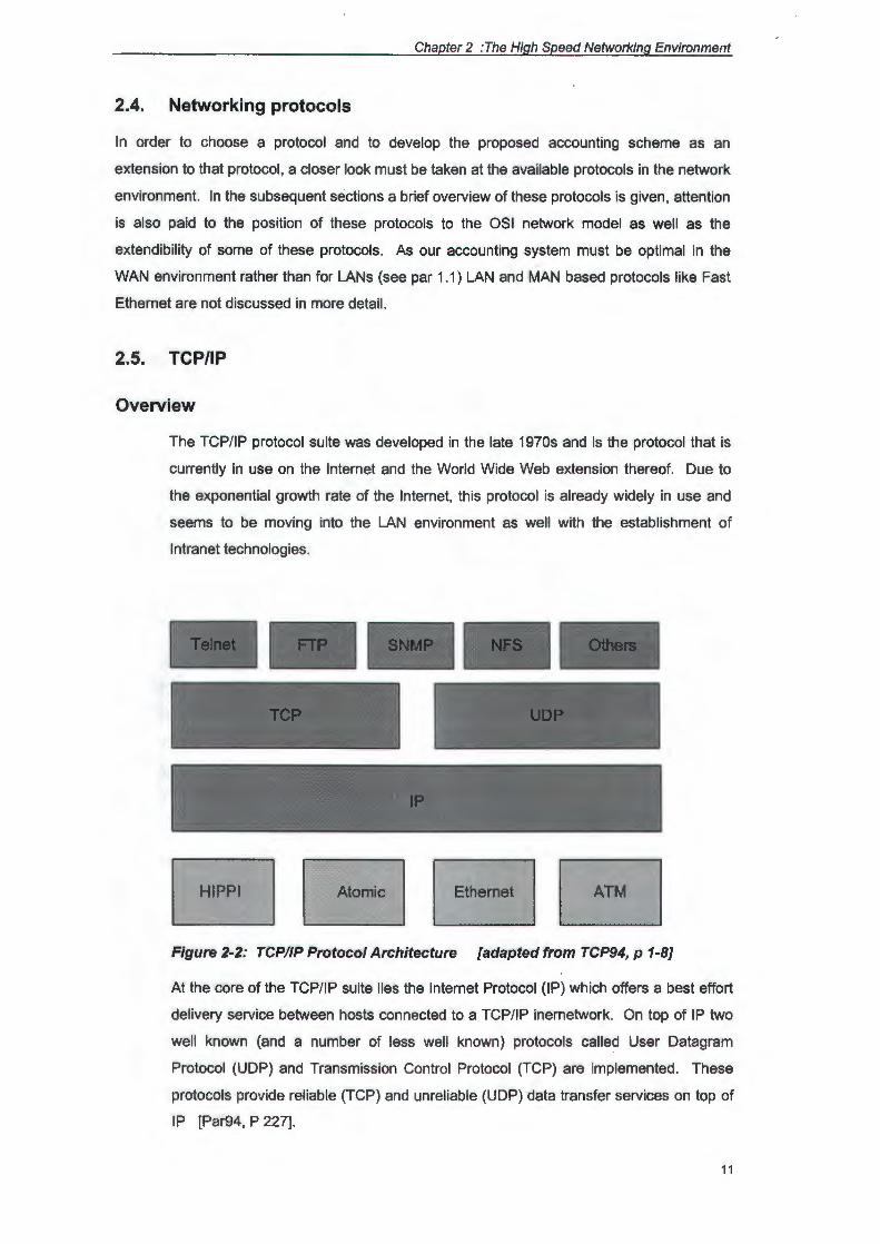
EJ Figure 2-2: TCP/IP Protocol Architecture [adapted from TCP94, p 1-8]
At the core of the TCP/IP suite lies the Internet Protocol (IP) which offers a best effort
delivery service between hosts connected to a TCP/IP inernetwork. On top of IP two
well known (and a number of less well known) protocols called User Datagram
Protocol (UDP) and Transmission Control Protocol (TCP) are implemented. These
protocols provide reliable (TCP) and unreliable (UDP) data transfer services on top of
IP [Par94, P 227].
11

Chapter 2 :The High Speed Networking Environment
IP hosts are identified by a 4 byte IP-address that is typically written as four separate
decimal numbers separated by dots (i.e. 155.237 .91.1 ). This address is normally split
into a network, subnetwork and host identifier. IP makes use of a special address in
order to support multicasting. As TCP does not support reliable multicasting this
function is implemented by means of UDP.
In order to support a reliable service (described by [Par94] as the in order delivery of a
stream of bytes), TCP requires that the TCP module at the host confirms correct
reception of each segment of a message. If confirmation is not received before a
certain time-out limit, the segment is resent. Flow control is done by means of a
sliding window, with the window size indicating the amount of segments that may be
outstanding during a particular time. Segments are also numbered in order to
uniquely identify them. To ensure correct delivery each segment also caries a
checksum.
Mapping TCP/IP to the OSI Model
Host-to-Host I :=:::;::Nelwo::::::::::rk::::::::::=: I In~ I
:====~=~= I = I
Figure 2-3: TCP/IP and the OSI model
The TCP/IP suite was developed about a decade before the OSI model , as such it
maps better to it's own four layered model, however it can be roughly mapped to the
OSI model as indicated in Fig 2-3 ..
Scalability to higher transmission speeds
Jacobson has indicated that TCP/IP can be adapted to run at Gigabit speeds, [Par94]
mentions that Cray's standard TCP/IP has been measured at 790 MB/s. These
adaptations should include:
• Better lookup techniques: the idea is to use lookup techniques with fast running
times and use caches wherever possible.
12
Chapter 2 :The High Speed Networking Environment
+ Reduced Checksum costs: faster checksums can be made by using a native
word size, by using trailing checksums or even leaving the checksum out.
+ Prediction: As TCP behavior is highly predictable, the TCP codepath can be
optimized accordingly rendering better performance for the average case
• Increasing the data in flight: By increasing the window size to correspond to the
product of a networks delay and bandwidth (with a corresponding increase in the
sequence number size), bandwidth can be used optimally.
Given these possible extensions, TCP/IP should be fast enough last into future
network environments. However, it still does not supply performance guarantees
regarding delay or bandwidth. A problem when implementing an accounting scheme
on top of this protocol, is that it would be difficult to implement in non routing network
devices (i.e. switches that does not perform level 3 switching).
2.5.2. FDDI
Overview
Fiber Distributed Data Interface (FDDI), is a set of standards that was developed by
Task Group X329.5 of the ANSI Accredited Standards Committee [Jai94]. FDDI uses
a timed token access method to access a dual ring topology at 100 Mb/s. (Although a
logical ring is used, the physical topology can be a star, or a ring.) This kind of
network makes provision for up to 500 stations connected no more than 2 km apart to
fiber that can be up to 200 km in total length for a single ring. FDDI uses a point to
point connection type with baseband signaling.
The FDDI protocol makes use of packets called frames. The maximum length per
packet is 4500 bytes, ignoring headers and trailers, the available space for data is in
the order of 4096 (4k) bytes. These frames can be transmitted by means of
synchronous or asynchronous traffic schemes. Normally synchronous traffic will be
used for delay sensitive packets, i.e. video and asynchronous for traffic that is less
sensitive in this regard i.e. data.
In order to make provision for high priority traffic during asynchronous communication
up to eight priority levels have been defined. Due to a scheme based on token
rotation time, only higher priority traffic will be transmitted during periods of high load.
FDDI uses fully distributed algorithms for fault recovery, clock synchronization and
topology control. Due to this factor, the rest of the network will detect if a certain
station has failed, and will attempt to continue operation without it. One method that
13
Chapter 2 :The High Speed Networking Environment
FDDI uses to increase fault tolerance is by unfolding the dual ring topology, into a
logical bus in case of an error on the ring. This is done by using a dual attached
station (DAS) to redirect the traffic around the problem. DASs can also be used to
supply load balancing between the two bi-directional rings.
Mapping FDDI to the OSI model
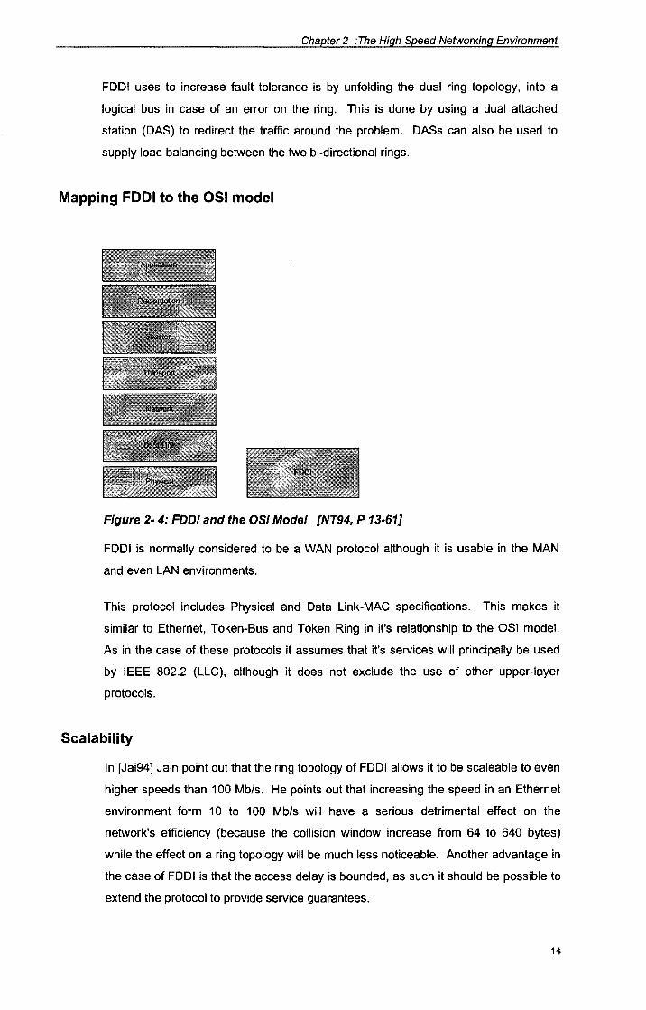
Figure 2- 4: FDDI and the OSI Model [NT94, P 13-61]
FDDI is normally considered to be a WAN protocol although it is usable in the MAN
and even LAN environments.
This protocol includes Physical and Data Link-MAC specifications. This makes it
similar to Ethernet, Token-Bus and Token Ring in it's relationship to the OSI model.
As in the case of these protocols it assumes that it's services will principally be used
by IEEE 802.2 (LLC), although it does not exclude the use of other upper-layer
protocols.
Scalability
In [Jai94] Jain point out that the ring topology of FDDI allows it to be scaleable to even
higher speeds than 100 Mb/s. He points out that increasing the speed in an Ethernet
environment form 10 to 100 Mb/s will have a serious detrimental effect on the
network's efficiency (because the collision window increase from 64 to 640 bytes)
while the effect on a ring topology will be much less noticeable. Another advantage in
the case of FDDI is that the access delay is bounded, as such it should be possible to
extend the protocol to provide service guarantees.
14

Chapter 2 :The High Speed Networking Environment
2.5.3. X.25
Overview
The X.25 protocol stack was defined by the CCITT (now ITU) in 1974. This protocol is
designed specifically for attaching computers to packet switched networks. The X.25
Datagram protocol was dropped in 1984 making end to end error control mandatory
for X.25 applications.
X.25 makes use of a point-to-point connection type to send synchronous traffic over a
Mesh/Hybrid topology. It uses packet switching over virtual circuits with LLC and
network layer flow control. Addressing is done on a channel basis with addresses
maintained per connection [NT94 p 13-64).
The protocol makes provision for both permanent and switched virtual circuits. Data
Terminal Equipment (DTE) on X.25 can handle multiple virtual circuits simultaneously.
The also provide end to end flow and error control.
· The X.25 architecture defines three layers. Layer one gives physical connectivity over
X.21, V.32, etc., while level two gives the methods for providing the connection
orientated data path. This is done over Link Access Procedures-Balanced protocol
(LAPB). Level three defines the interface between the data terminal equipment (i.e.
computers) and the data circuit terminating equipment (the network). X.25 does not
make provision for the definition of routing algorithms, but instead leaves that to the
vendors to implement [NT94 p 13-64).
In South Africa national X.25 connections are available from Telcom at various
transmission speeds.
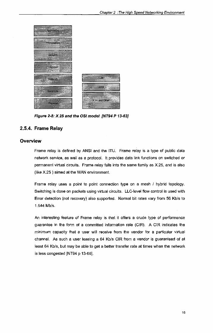
Mapping X.25 to the OSI Model
X.25 and its supporting protocols can be mapped to the lower three layers of the OSI
model. X.25 itself can be seen to fit into the Network layer and upper part of the Data
Link layer.
15
Chapter 2 :The High Speed Networking Environment
Figure 2-5: X.25 and the OSI model [NT94 P 13-63]
2.5.4. Frame Relay
Overview
Frame relay is defined by ANSI and the ITU. Frame relay is a type of public data
network service, as well as a protocol. It provides data link functions on switched or
permanent virtual circuits. Frame relay falls into the same family as X.25, and is also
(like X.25) aimed at the WAN environment.
Frame relay uses a point to point connection type on a mesh I hybrid topology.
Switching is done on packets using virtual circuits. LLC-level flow control is used with
Error detection (not recovery) also supported. Normal bit rates vary from 56 Kb/s to
1.544 Mb/s.
An interesting feature of Frame relay is that it offers a crude type of performance
guarantee in the form of a committed information rate (CIR). A CIR indicates the
minimum capacity that a user will receive from the vendor for a particular virtual
channel. As such a user leasing a 64 Kb/s CIR from a vendor is guaranteed of at
least 64 Kb/s, but may be able to get a better transfer rate at times when the network
is less congested [NT94 p 13-66].
16
Chapter 2 : The High Speed Networking Environment
Mapping Frame Relay to the OSI model
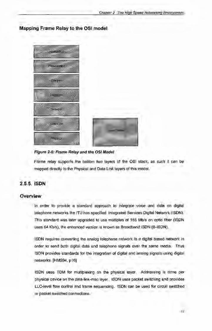
Figure 2-6: Frame Relay and the OSI Model
Frame relay supports the bottom two layers of the OSI stack, as such it can be
mapped directly to the Physical and Data Link layers of this model.
2.5.5. ISDN
Overview
In order to provide a standard approach to integrate voice and data on digital
telephone networks the ITU has specified Integrated Services Digital Network (ISDN).
This standard was later upgraded to use multiples of 155 Mb/s on optic fiber (ISDN
uses 64 Kb/s), the enhanced version is known as Broadband ISDN (B-ISDN).
ISDN requires converting the analog telephone network to a digital based network in
order to send both digital data and telephone signals over the same media. Thus
ISDN provides standards for the integration of digital and analog signals using digital
networks. [HMS94, p16]
ISDN uses TDM for multiplexing on the physical layer. Addressing is done per
physical device on the data-link-mac layer. ISDN uses packet switching and provides
LLC-level flow control and frame sequencing. ISDN can be used for circuit switched
or packet switched connections.
17
Chapter 2 :The High Speed Networking Environment
Users can access several standard rate multiplexed digital channels known as bit
pipes. These pipes are available as:
+ Channel A :
+ Channel B :
+ Channel C:
+ Channel D:
+ Channel E:
+ Channel H:
4 KHz analog
64 Kb/s digital
8 or 16 Kb/s digital for out of band signaling
16 or 64 Kb/s digital for out of band signaling
64 Kb/s digital for internal ISDN signaling
384, 1536 or 1920 Kb/s digital
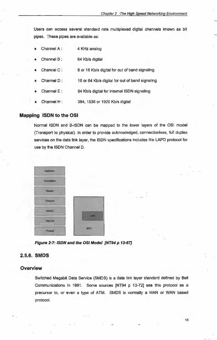
Mapping ISDN to the OSI
Normal ISDN and B-ISDN can be mapped to the lower layers of the OSI model
{Transport to physical). In order to provide acknowledged, connectionless, full duplex
services on the data link layer, the ISDN specifications includes the LAPD protocol for
use by the ISDN Channel D.
Transport
Oalal.Jnk -!SON
Figure 2-7: ISDN and the OSI Model [NT94 p 13-67]
2.5.6. SMDS
Overview
Switched Megabit Data Service (SMDS) is a data link layer standard defined by Bell
Communications in 1991. Some sources [NT94 p 13-72] see this protocol as a
precursor to, or even a type of ATM . SMDS is normally a MAN or WAN based
protocol.
18
Chapter 2 :The High Speed Networking Environment
SMDS is a connectionless data link layer protocol that can be implemented on DQDB
SONET. It performs cell switching using Isochronous transmission synchronization,
bit rates varies between 1.544 and 45 Mb/s.
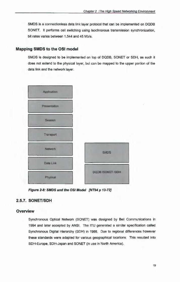
Mapping SMDS to the OSI model
SMDS is designed to be implemented on top of DQDB, SONET or SDH, as such it
does not extend to the physical layer, but can be mapped to the upper portion of the
data link and the network layer.
Application
Presentation
Session
Transport
Network SMDS
Data Link
DQDB /SONET /SDH
Physical
Figure 2-8: SMDS and the OSI Model [NT94 p 13-72}
2.5.7. SONET/SDH
Overview
Synchronous Optical Network (SONET) was designed by Bell Communications in
1984 and later accepted by ANSI. The ITU generated a similar specification called
Synchronous Digital Hierarchy (SDH) in 1988. Due to regional differences however
these standards were adapted for various geographical locations. This resulted into
SDH-Europe, SDH-Japan and SONET (in use in North America).
19
Chapter 2 :The High Speed Networking Environment
SONET and SDH provide specifications for physical services in a WAN environment.
SONET/SDH uses point to point connections in a MESH or Ring physical topology.
TDM is used for multiplexing [NT94 P 13-75]. SONET and SDH can be used as
physical layer specifications on which FDDI, DQDB and ATM can be based.
SONET can use various data rates, specified as STS/OC designations:
• oc 1
+ OC2
+ OC3
+ OC24
51.84 Mb/s
155.52 Mb/s
622.08 Mb/s
1 244.16 Mb/s
These rates differ between the North American and European regions due to
difference in standard data rates provided by service providers in these regions. OC
rates are used in North America while the CCITT have specified an STM designation
with STM-1 = OC-3 [Par94 P 29].
SONET sends data in frames. Each frame is seen as a two dimensional block of
bytes, consisting of 90 columns and 9 rows. For a given OC rate the unit of
transmission is the corresponding amount of frames, i.e. OC-3 handles three frames
at a time.
20
Chapter 2 :The High Speed Networking Environment
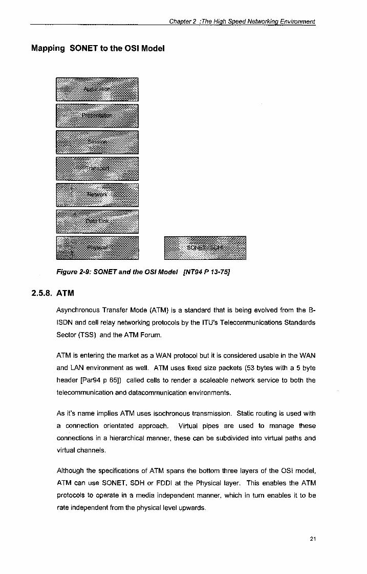
Mapping SONET to the OSI Model
Figure 2-9: SONETand the OSI Model [NT94P13-75]
2.5.8. ATM
Asynchronous Transfer Mode (ATM) is a standard that is being evolved from the B
ISON and cell relay networking protocols by the ITU's Telecommunications Standards
Sector (TSS) and the ATM Forum.
ATM is entering the market as a WAN protocol but it is considered usable in the WAN
and LAN environment as well. ATM uses fixed size packets (53 bytes with a 5 byte
header [Par94 p 65)) called cells to render a scaleable network service to both the
telecommunication and datacommunication environments.
As it's name implies ATM uses isochronous transmission. Static routing is used with
a connection orientated approach. Virtual pipes are used to manage these
connections in a hierarchical manner, these can be subdivided into virtual paths and
virtual channels.
Although the specifications of ATM spans the bottom three layers of the OSI model,
ATM can use SONET, SDH or FDDI at the Physical layer. This enables the ATM
protocols to operate in a media independent manner, which in turn enables it to be
rate independent from the physical level upwards.
21
Chapter 2 :The High Speed Networking Environment
In order to group the types of applications that can run on the upper layers of an ATM
network, the ITU-TSS has defined a number of standards called the I-series (NT94 p
13-71). These standards, identifies a number of classes of service for upper layer
protocols:
+ Constant bit-rate traffic
+ Variable bit rate delay sensitive data
+ Connection oriented data
+ Connectionless data
Each of these classes is meant to be optimized for a different type of data stream (i.e.
video over the constant bit rate, etc.). In order to interface between these upper layer
protocols and the ATM layer, an ATM adaption layer protocol (AAL) is used. Initially
four AALs were defined, one for each of the above mentioned classes. A fifth AAL
were later defined, both as an enhancement and a simplification to the AAL 3/4
combination.
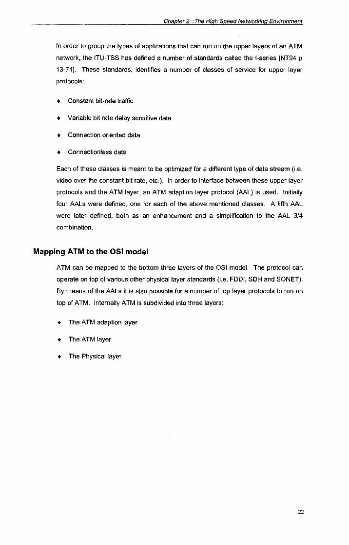
Mapping ATM to the OSI model
ATM can be mapped to the bottom three layers of the OSI model. The protocol can
operate on top of various other physical layer standards (i.e. FDDI, SDH and SON ET).
By means of the AALs it is also possible for a number of top layer protocols to run on
top of ATM. Internally ATM is subdivided into three layers:
+ The A TM adaption layer
+ The A TM layer
+ The Physical layer
22
Chapter 2 :The High Speed Networking Environment
Application
Presentation
Session
Transport
Network
ATM
Data Link
Physical FDDI I SONET I SOHi
Figure 2-10: ATM and the OSI Model
Scalability
One of the strong points of ATM is that it's supported bit rates are already scaleable.
As such ATM can be scaled into the Gigabit range as and when required . Partridge
[Par94 p 61] mentions that the current ATM standards (in North America) already
make provision for users to access the network at speeds of up to 622 Mb/s. (A
number of switch manufacturers providing ATM switches (i.e. Hughes) already boasts
an ATM bit rate well within the Gigabit range on their hardware backplanes.)
2.5.9. Other protocols
In [Par94] Partridge discuss various other high speed protocols, like ATOMIC, HIPI,
DQDB, etc. However, it is the intention that the work done in this study should be of
practical value after completion. Thus the discussion regarding protocols in this
section will be limited to those that are most prevalent in the industry today (or
perceived to be so in the near future) . As such these other protocols will be seen to
fall outside the scope of this study.
2.5.1 O.The complete protocol picture
In the previous sections a number of protocols have been discussed. These protocols
have been shown to vary regarding speed (bit rates) as well as application area.
Some of these have been pointed out to fit better into a MAN/WAN and others better
23
f/I -.c ~ ..c: -"t:I 'i "t:I c CV cc
Chapter 2 :The High Speed Networking Environment
into the WAN/Internet environment, they were also shown to map to various levels of
the OSI model.
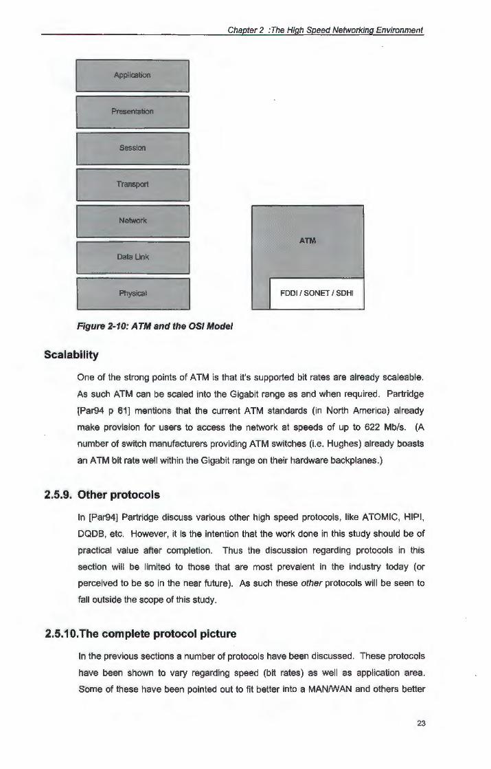
In [Ben94 p 1 O] the following summary of protocols, their bandwidth and application
area is given:
1000
ATM
100 Fast Ethernet
10
Ethernet
LAN Campus MAN WAN
Network Type
Figure 2-11: Protocols vs Network Type
Partridge points out that there is more than one way to view ATM. These views vary
from seeing ATM as just another network service to seeing it as a protocol in its own
right. An interesting point of view is discussed in [Par94 p 86], describing ATM as a
service that replaces bits on a wire with cells on a wire.
When ATM is viewed as a protocol in its own right, it also implies that it can be
combined with other protocols in the networking environment. This is exactly what
some of the Internet Engineering Task Force's working groups have noted, i.e. the IP
over ATM Working Group. This group is developing ATM internetworking architecture
models in order to define the IP over ATM protocols.
In [HMS94 p 19] the advantages of using ATM over fiber are pointed out, [NT94] also
points out that one way to do this is to use SONET on the physical layer. Once again
this will imply a combination of protocols.
24
Chapter 2 :The High Speed Networking Environment
It is also pointed out in [Ben94 p 25] how ATM can be made to emulate normal
Ethernet LAN technology (for the sake of existing legacy devices) by means of LAN
emulation (LES).
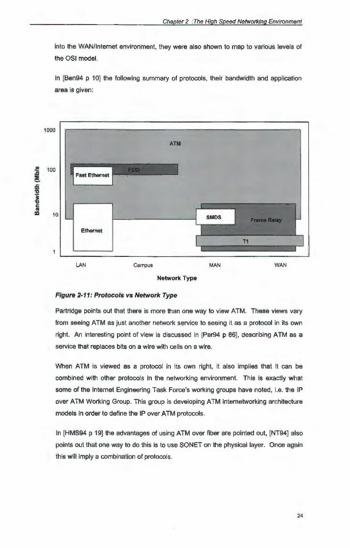
Given the speed, scalability and media independence of ATM, the growing popularity
and increasing use of TCP/IP as well as the expected migration of the telephone
community to SON ET, a protocol stack consisting of the combination of these may be
particularly successful.
Application
Presentation
Session
Transport
Network
Data Link
Physical SONET/SDHI
Figure 2-12: Combination of protocols
2.6. High speed networking devices
When considering a high speed networking protocol that is to operate in the WAN I
Internetwork environment, the network devices deployed on such a network is bound to have
an effect.
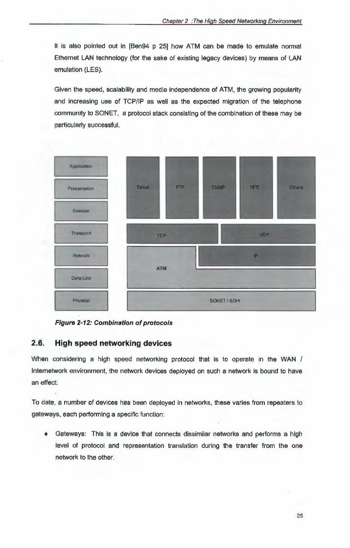
To date, a number of devices has been deployed in networks, these varies from repeaters to
gateways, each performing a specific function :
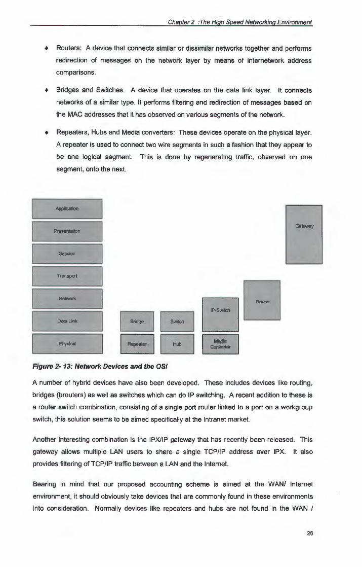
+ Gateways: This is a device that connects dissimilar networks and performs a high
level of protocol and representation translation during the transfer from the one
network to the other.
25
Chapter 2 :The High Speed Networking Environment
• Routers: A device that connects similar or dissimilar networks together and performs
redirection of messages on the network layer by means of internetwork address
comparisons.
• Bridges and Switches: A device that operates on the data link layer. It connects
networks of a similar type. It performs filtering and redirection of messages based on
the MAC addresses that it has observed on various segments of the network.
• Repeaters, Hubs and Media converters: These devices operate on the physical layer.
A repeater is used to connect two wire segments in such a fashion that they appear to
be one logical segment. This is done by regenerating traffic, observed on one
segment, onto the next.
Application
Gateway Presentation
Session
Transport
Data Llnk
Physical
Figure 2- 13: Network Devices and the OSI
A number of hybrid devices have also been developed. These includes devices like routing,
bridges (brouters) as well as switches which can do IP switching. A recent addition to these is
a router switch combination, consisting of a single port router linked to a port on a workgroup
switch, this solution seems to be aimed specifically at the Intranet market.
Another interesting combination is the IPX/IP gateway that has recently been released . This
gateway allows multiple LAN users to share a single TCP/IP address over IPX. It also
provides filtering of TCP/IP traffic between a LAN and the Internet.
Bearing in mind that our proposed accounting scheme is aimed at the WAN/ Internet
environment, it should obviously take devices that are commonly found in these environments
into consideration . Normally devices like repeaters and hubs are not found in the WAN I
26
Chapter 2 :The High Speed Networking Environment
Internet environment, although they are not completely restricted to LAN applications. Most
Internetwork environments are managed by means of routers. Until not to long ago this has
also been the case in the WAN environment recently however a number of these routers have
been replaced by backbone switches.
This utilization of routers and switches in the WAN I Internet environment implies that
whichever protocol we choose for implementation of the proposed accounting scheme, must
be able to operate on the network and data link layers of the OSI model.
2. 7. Accounting in a high speed networking environment
Given the discussion above regarding network protocols and devices, we are now in a position
to motivate the choice of ATM as an underlying protocol for the network accounting scheme.
In order to validate the choice, the following criteria should be born in mind:
+ The protocol must be able to handle performance guarantees;
+ It must be acceptable to the IT and networking market;
+ It must be usable in the WAN/Internet environment;
+ It must be scaleable to Gigabit speeds.
When considering the network protocol to hardware interface, it is obvious that the protocol in
question should also make provision for accounting across interfaces like:
+ routers
+ switches
+ switch-router combinations (i.e. the IP switch)
As far as switches are concerned, this means that it must be possible to implement the
protocol in silicon, as many new generation switches have moved away from RISC based to
ASIC based systems.
Based on these considerations, the ATM protocol seems the best suited to the task in hand.
As such, it will no doubt be relevant to have a closer look at this particular protocol. This is
done in chapter three.
2.8. Summary
In this chapter it was indicated current mature and stable, but slow network technologies will
no longer be sufficient to render a usable network service. As such, newer, high speed
networking technologies should be considered in order to cope with the ever increasing
27
Chapter 2 :The High Speed Networking Environment
demand in bandwidth. It was also pointed out that this technology will include high speed
protocols like ATM as well as high speed networking devices like switches. These were briefly
discussed in order to aid the discussion in following chapters regarding the proposed Network
Accounting System, which makes use of these protocols and devices.
28
Chapter 3
ATM Protocols
3.1. Introduction
In the previous chapter a general overview of the high speed networking environment was
given. In this chapter we concentrate on Asynchronous Transfer Mode (ATM).
Benham [Ben94 p1] points out that ATM is changing the way we think about traditional data
and telecommunications. Although ATM started off in the telecommunications industry, it's
application to data communication networks is fast surpassing that of pure
telecommunications [Par94]. In support of [HMS94], Benham also mentions that ATM has
started off as just another method of moving data across B-ISDN networks, but that it has
since developed into a core network protocol, giving a uniform method of transporting,
multiplexing, routing and switching all types of traffic at unprecedented speeds.
3.2. Defining ATM
Partridge [Par94 p 63] and [HMS94 p 16] indicate that Asynchronous Transfer Mode is a
connection-oriented, cell-based hierarchical, network technology which is rate and media
independent.
In order to clarify this definition, each of the separate terms is discussed briefly:
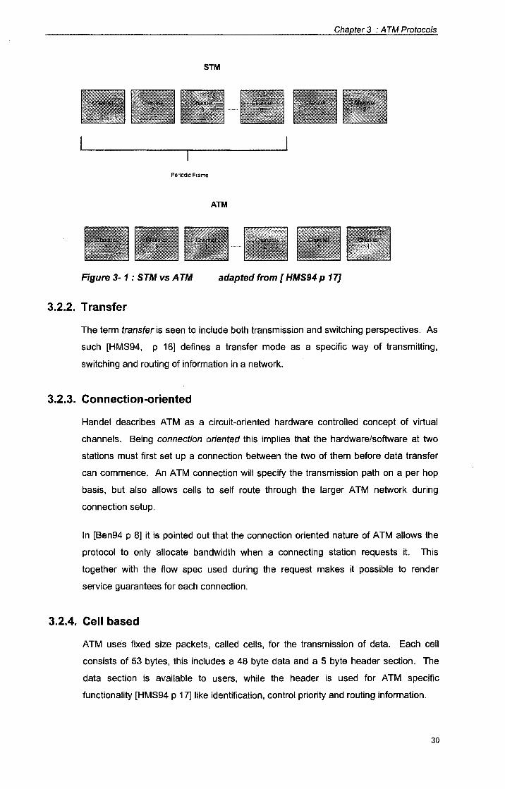
3.2.1. Asynchronous
In [HMS94] asynchronous is explained to refer to the irregular recurrence pattern
which may be displayed by cells belonging to the same connection, when viewed
within the context of multiplexed transmissions.
This situation can best be explained by means of a diagram, as seen in Fig 3.1. The
Synchronous transfer mode only makes provision for the use of a specific slot (in a
time referenced scale) by a specific channel. This is not the case in ATM where
multiplexing and switching of cells are done independent of the application itself.
Chapter 3 : A TM Protocols
STM
Periodic Frame
ATM
Figure 3- 1 : STM vs A TM adapted from [ HMS94 p 17]
3.2.2. Transfer
The term transfer is seen to include both transmission and switching perspectives. As
such [HMS94, p 16] defines a transfer mode as a specific way of transmitting,
switching and routing of information in a network.
3.2.3. Connection-oriented
Handel describes ATM as a circuit-oriented hardware controlled concept of virtual
channels. Being connection oriented this implies that the hardware/software at two
stations must first set up a connection between the two of them before data transfer
can commence. An ATM connection will specify the transmission path on a per hop
basis, but also allows cells to self route through the larger A TM network during
connection setup.
In [Ben94 p 8] it is pointed out that the connection oriented nature of ATM allows the
protocol to only allocate bandwidth when a connecting station requests it. This
together with the flow spec used during the request makes it possible to render
service guarantees for each connection.
3.2.4. Cell based
ATM uses fixed size packets, called cells, for the transmission of data. Each cell
consists of 53 bytes, this includes a 48 byte data and a 5 byte header section. The
data section is available to users, while the header is used for ATM specific
functionality [HMS94 p 17] like identification, control priority and routing information.
30
Chapter 3 : A TM Protocols
According to Partridge [Par94 p 49] as well as [Ben94 p 8] the use of cells has the
advantage that it:
+ provides easier support for multicasting,
+ offers better multiplexing schemes,
+ allows the mixing of various types of traffic due to low latency per cell and
+ allows for user access at scaleable data rates.
3.2.5. Hierarchical
This indicates the structure of the network itself. Partridge foresees that ATM
networks will be structured in a similar manner to the current hierarchy in the
telecommunication networks. Thus, a user's computer may be connected to a
regional ATM provider who in turn will be connected to the National provider who will
be connected to the International provider.
This structure is also incorporated in the manner that connections between networks
and network equipment are done. As such, the method used will vary, depending on
the position of the connecting point in the hierarchy. ATM user equipment will thus
connect to the network by means of a user network interface (UNI) while networks will
connect by means of a network to network interface (NNI} [Par94 p 63].
3.2.6. Rate and media independence
By definition, the ATM protocol is not set to work only at a specific data rate (like
Ethernet) or over a specific media type (like FDDI}. Due to the fact that it can use
various other protocols at the data link layer, ATM can run at data rates compatible to
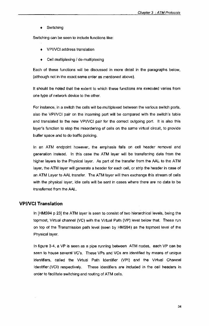
these types over media supported by them. This makes ATM implementations
independent of a specific data rate or media type.
3.3. ATM protocol description
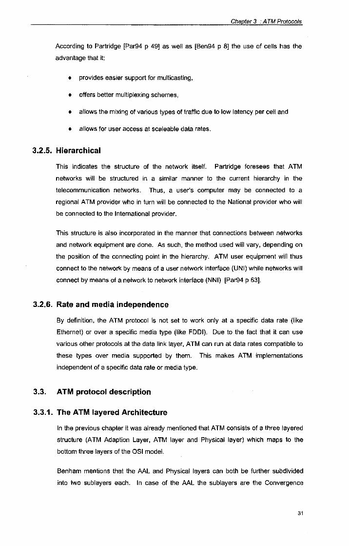
3.3.1. The ATM layered Architecture
In the previous chapter it was already mentioned that ATM consists of a three layered
structure (ATM Adaption Layer, ATM layer and Physical layer) which maps to the
bottom three layers of the OSI model.
Benham mentions that the AAL ·and Physical layers can both be further subdivided
into two sublayers each. In case of the AAL the sublayers are the Convergence
31
Chapter 3 : A TM Protocols
Sublayer (CS) and the Segmentation and Reassembly sublayer (SAR). The Physical
layer in it's turn can be subdivided into a Transmission Convergence (TC) part and a
Physical Medium Dependent layer (PMD).
User Plane
ATM Adaption Layer
ATM Layer
Physical Layer
Figure 3- 2 : A TM architecture
Control Plane
Management Plane
In [Ben94 p 34] Benham indicates that except for layers the ATM model can also be
seen to include a number of planes, rendering functions that span all the layers in the
architecture model. These are the User Plane, the Control Plane and the
Management Plane.
The Management Plane offers network management functionality for both the network
and endpoints. The Control Plane grants network wide control signaling (i.e. the
signaling used to set up Switched Virtual Circuits (SVCs) between endpoints. The
User plane's function is to render end-to-end data transfers.
3.3.2. ATM physical layer functions
The main function of the ATM physical layer is to define characteristics specific to the
physical medium (i.e. bit timing) and to pass the cells from this media to the ATM layer
and the opposite.
32
Chapter 3 : A TM Protocols
To make ATM media independent it was necessary to segment the physical layer into
two sublayers. That part of the physical layer functions that are independent of the
media in use, is done on the TC layer, while the media dependent functions are
handled on the PMD layer.
Each PMD is aimed at a specific type of physical medium. The PMDs include
standards for bit timing as well as proper cabling specifications. From this sublayer
upwards the ATM functions are implemented in the same way regardless of the
medium used. According to Benham [Ben94], PMD layer definitions exist for o~tical
fiber, Cat-3 and Cat-5 UTP.
The TC sublayer fulfills a convergence function, this is done by extracting (delineating)
cells from the bit stream presented to it by the PMD. To do this, the Header Error
Control (HEC) field in the ATM header is used. Other functions of the TC layer
include the adaption of the ATM layer cell stream to the cell rate of the physical layer,
as well as error checking by testing the HEC fields.
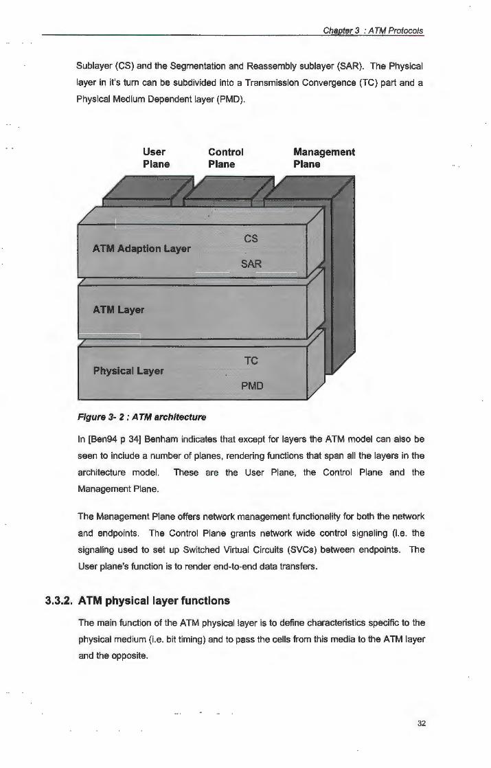
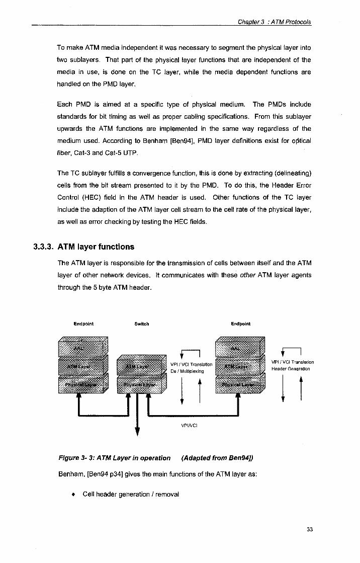
3.3.3. ATM layer functions
The ATM layer is responsible for the transmission of cells between itself and the A TM
layer of other network devices. It communicates with these other ATM layer agents
through the 5 byte ATM header.
Endpoint Switch
VPI I VCI Translation
De I Multiplexing
1 I VPINCI
Endpoint
Figure 3- 3: A TM Layer in operation (Adapted from Ben94])
Benham, [Ben94 p34] gives the main functions of the ATM layer as:
• Cell header generation I removal
VPI I VCI Translation
Header Generation
1 r
33
Chapter 3 : A TM Protocols
+ Switching
Switching can be seen to include functions like:
+ VPINCI address translation
+ Cell multiplexing I de-multiplexing
Each of these functions will be discussed in more detail in the paragraphs below,
(although not in the exact same order as mentioned above).
It should be noted that the extent to which these functions are executed varies from
one type of network device to the other.
For instance, in a switch the cells will be multiplexed between the various switch ports,
also the VPINCI pair on the incoming port will be compared with the switch's table
and translated to the new VPINCI pair for the correct outgoing port. It is also this
layer's function to stop the misordering of cells on the same virtual circuit, to provide
buffer space and to do traffic policing.
In an ATM endpoint however, the emphasis falls on cell header removal and
generation instead. In this case the ATM layer will be transferring data from the
higher layers to the Physical layer. As part of the transfer from the AAL to the ATM
layer, the ATM layer will generate a header for each cell, or strip the header in case of
an ATM Layer to AAL transfer. The ATM layer will then exchange this stream of cells
with the physical layer, idle cells will be sent in cases where there are no data to be
transferred from the AAL.
VPINCI Translation
In [HMS94 p 23] the ATM layer is seen to consist of two hierarchical levels, being the
topmost, Virtual channel (VC) with the Virtual Path (VP) level below that. These run
on top of the Transmission path level (seen by HMS94} as the topmost level of the
Physical layer.
In figure 3-4, a VP is seen as a pipe running between ATM nodes, each VP can be
seen to house several VC's. These VPs and VCs are identified by means of unique
identifiers, called the Virtual Path Identifier (VPI} and the Virtual Channel
ldentifier.(VCI) respectively. These identifiers are included in the cell headers in
order to facilitate switching and routing of ATM cells.
34
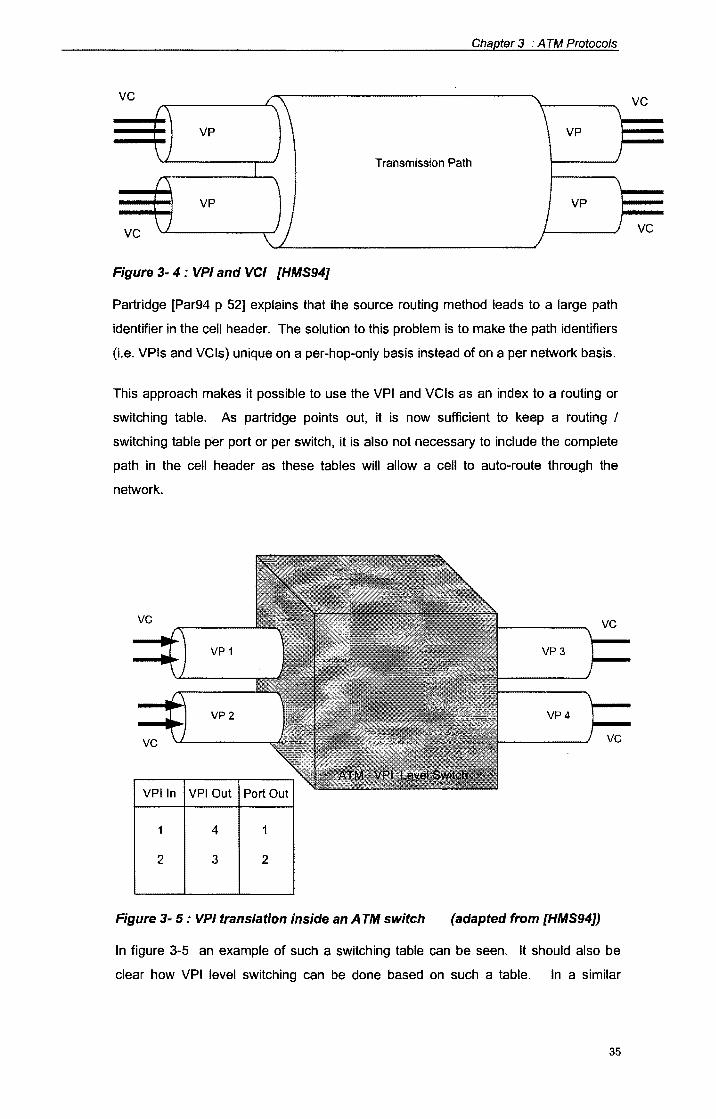
Chapter 3 : A TM Protocols
vc /\\ '\ !''\
\ VP VP
\) ) Transmission Path I
{'\ ' ' VP VP
vc \ i \}) J )
Figure 3- 4 : VP/ and VCI [HMS94]
Partridge [Par94 p 52] explains that the source routing method leads to a large path
identifier in the cell header. The solution to this problem is to make the path identifiers
(i.e. VPls and VCls} unique on a per-hop-only basis instead of on a per network basis.
This approach makes it possible to use the VPI and VCls as an index to a routing or
switching table. As partridge points out, it is now sufficient to keep a routing I
switching table per port or per switch, it is also not necessary to include the complete
path in the cell header as these tables will allow a cell to auto-route through the
network.
vc vc
VP 1 VP3
VP2 VP4
vc vc
VPI In VPI Out
4
2 3 2
Figure 3- 5 : VP/ translation inside an A TM switch (adapted from [HMS94])
In figure 3-5 an example of such a switching table can be seen. It should also be
clear how VPI level switching can be done based on such a table. In a similar
35
vc
vc
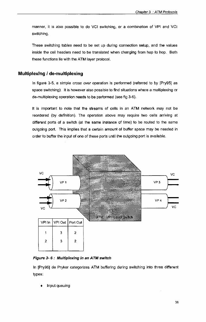
Chapter 3 : A TM Protocols
manner, it is also possible to do VCI switching, or a combination of VPI and VCI
switching.
These switching tables need to be set up during connection setup, and the values
inside the cell headers need to be translated when changing from hop to hop. Both
these functions lie with the ATM layer protocol.
Multiplexing I de-multiplexing
In figure 3-5, a simple cross over operation is performed (referred to by [Pry95] as
space switching). It is however also possible to find situations where a multiplexing or
de-multiplexing operation needs to be performed (see fig 3-6).
It is important to note that the streams of cells in an ATM network may not be
reordered (by definition). The operation above may require two cells arriving at
different ports of a switch (at the same instance of time) to be routed to the same
outgoing port. This implies that a certain amount of buffer space may be needed in
order to buffer the input of one of these ports until the outgoing port is available.
vc
VP 1 VP3
VP2 VP4
vc vc
VPI In VPI Out
3 2
2 3 2
Figure 3- 6 : Multiplexing in an A TM switch
In [Pry95] de Pryker categorizes ATM buffering during switching into three different
types:
+ Input queuing
36
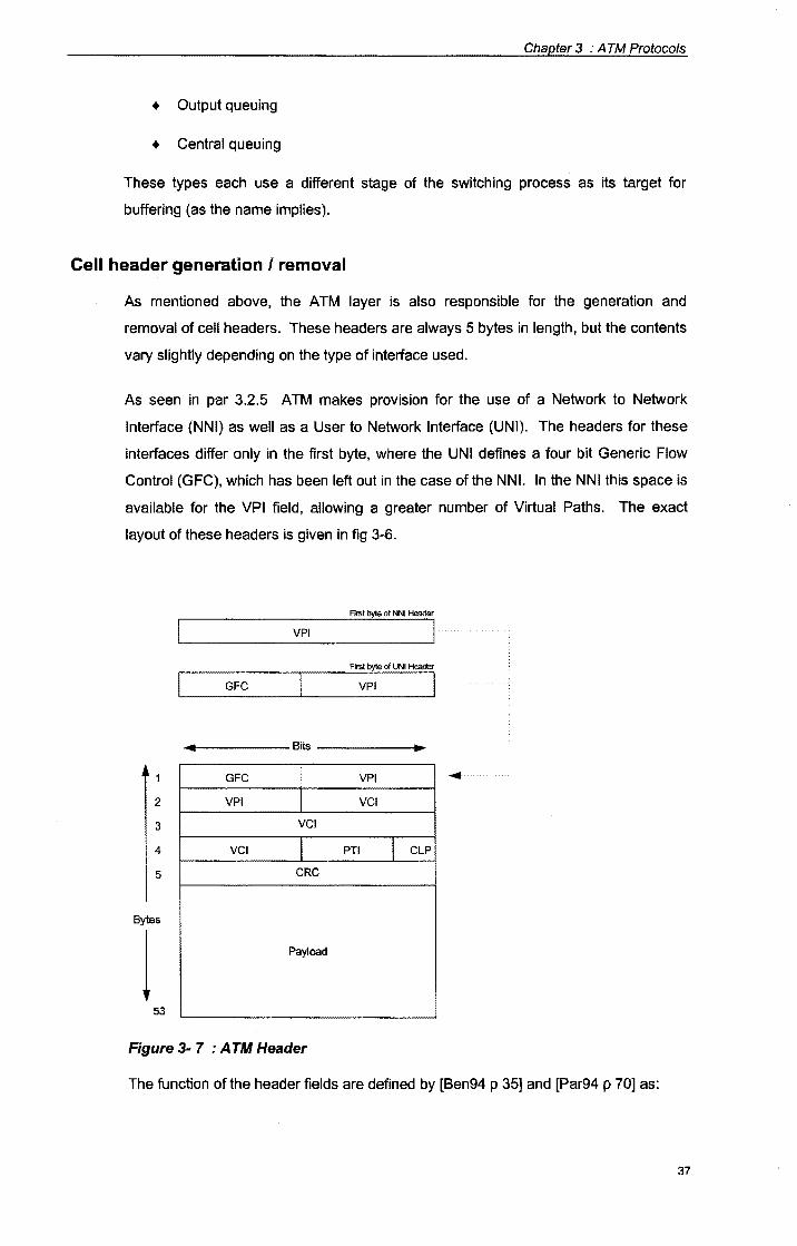
Chapter 3 : A TM Protocols
+ Output queuing
+ Central queuing
These types each use a different stage of the switching process as its target for
buffering (as the name implies).
Cell header generation I removal
As mentioned above, the A TM layer is also responsible for the generation and
removal of cell headers. These headers are always 5 bytes in length, but the contents
vary slightly depending on the type of interface used.
As seen in par 3.2.5 ATM makes provision for the use of a Network to Network
Interface (NNI) as well as a User to Network Interface (UNI). The headers for these
interfaces differ only in the first byte, where the UNI defines a four bit Generic Flow
Control (GFC), which has been left out in the case of the NNI. In the NNI this space is
available for the VPI field, allowing a greater number of Virtual Paths. The exact
layout of these headers is given in fig 3-6.
First byte of NNI Header
VPI
First byte of UNI Header
GFC VPI I
-------Bits -------"~
2
3
4
5
Bytes
l 53
GFC
VPI
VCI
I VCI
I CRC
Payload
Figure 3- 7 : A TM Header
VPI
VCI
PTI I CLP
...
The function of the header fields are defined by [Ben94 p 35] and [Par94 p 70] as:
37
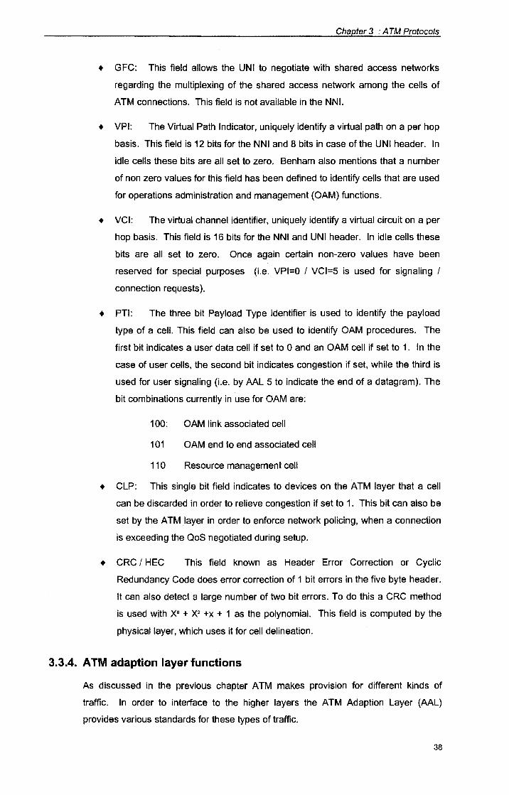
Chapter 3 : A TM Protocols
+ GFC: This field allows the UNI to negotiate with shared access networks
regarding the multiplexing of the shared access network among the cells of
ATM connections. This field is not available in the NNI.
+ VPI: The Virtual Path Indicator, uniquely identify a virtual path on a per hop
basis. This field is 12 bits for the NNI and 8 bits in case of the UNI header. In
idle cells these bits are all set to zero. Benham also mentions that a number
of non zero values for this field has been defined to identify cells that are used
for operations administration and management (OAM) functions.
+ VCI: The virtual channel identifier, uniquely identify a virtual circuit on a per
hop basis. This field is 16 bits for the NNI and UNI header. In idle cells these
bits are all set to zero. Once again certain non-zero values have been
reserved for special purposes (i.e. VPl=O I VCl=5 is used for signaling I
connection requests).
+ PTI: The three bit Payload Type identifier is used to identify the payload
type of a cell. This field can also be used to identify OAM procedures. The
first bit indicates a user data cell if set to 0 and an OAM cell if set to 1. In the
case of user cells, the second bit indicates congestion if set, while the third is
used for user signaling (i.e. by AAL 5 to indicate the end of a datagram). The
bit combinations currently in use for OAM are:
100: OAM link associated cell
101 OAM end to end associated cell
110 Resource management cell
+ CLP: This single bit field indicates to devices on the ATM layer that a cell
can be discarded in order to relieve congestion if set to 1. This bit can also be
set by the ATM layer in order to enforce network policing, when a connection
is exceeding the QoS negotiated during setup.
+ CRC/ HEC This field known as Header Error Correction or Cyclic
Redundancy Code does error correction of 1 bit errors in the five byte header.
It can also detect a large number of two bit errors. To do this a CRC method
is used with X8 + X2 +x + 1 as the polynomial. This field is computed by the
physical layer, which uses it for cell delineation.
3.3.4. ATM adaption layer functions
As discussed in the previous chapter ATM makes provision for different kinds of
traffic. In order to interface to the higher layers the ATM Adaption Layer (AAL)
provides various standards for these types of traffic.
38
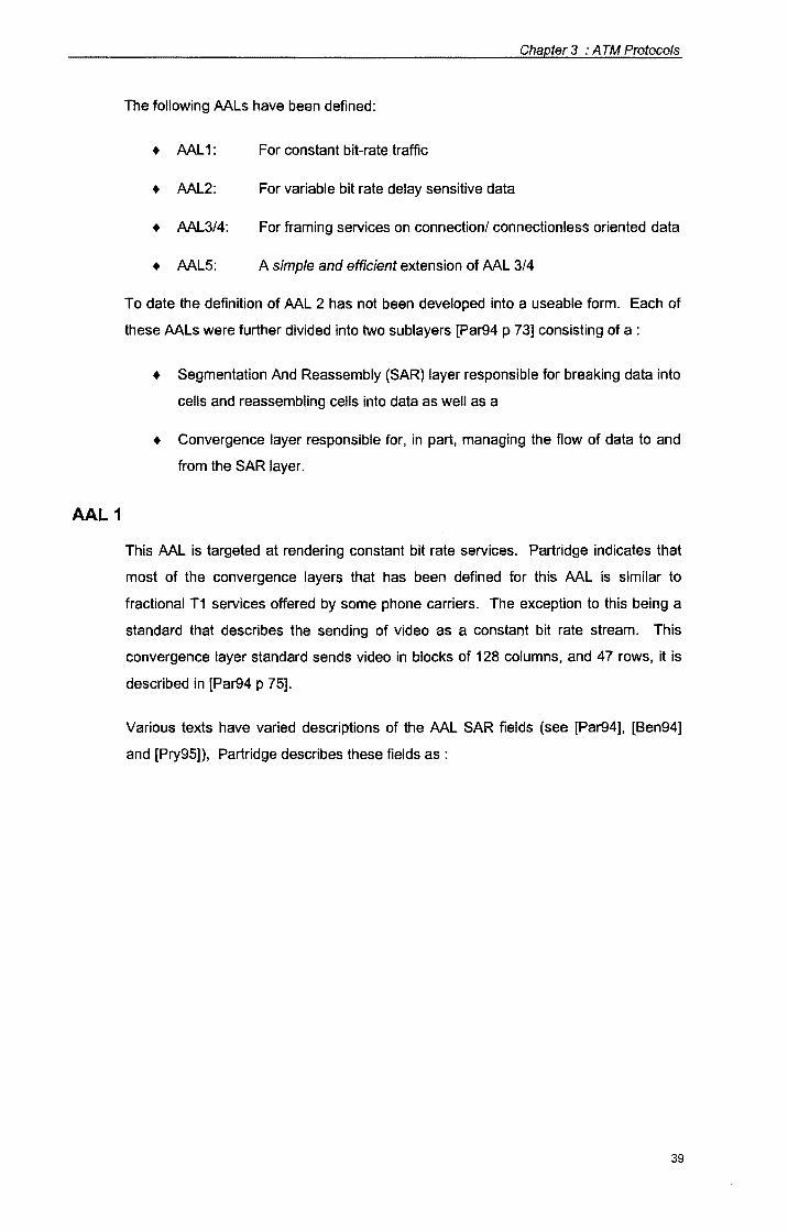
AAL 1
Chapter 3 : A TM Protocols
The following MLs have been defined:
+ ML1: For constant bit-rate traffic
+ ML2: For variable bit rate delay sensitive data
+ ML3/4: For framing services on connection/ connectionless oriented data
+ ML5: A simple and efficient extension of ML 3/4
To date the definition of ML 2 has not been developed into a useable form. Each of
these MLs were further divided into two sublayers [Par94 p 73] consisting of a :
• Segmentation And Reassembly (SAR) layer responsible for breaking data into
cells and reassembling cells into data as well as a
+ Convergence layer responsible for, in part, managing the flow of data to and
from the SAR layer.
This ML is targeted at rendering constant bit rate services. Partridge indicates that
most of the convergence layers that has been defined for this ML is similar to
fractional T1 services offered by some phone carriers. The exception to this being a
standard that describes the sending of video as a constant bit rate stream. This
convergence layer standard sends video in blocks of 128 columns, and 47 rows, it is
described in [Par94 p 75].
Various texts have varied descriptions of the ML SAR fields (see [Par94], [Ben94]
and [Pry95]), Partridge describes these fields as :
39

Chapter 3 : A TM Protocols
1 bit
CSI
2 bits
SC
2 1 bits bit
CRC
Parity
47 bytes
Data
Figure 3- 8 : AAL 1 SAR Format
+ CSI convergence sublayer indicator used for signaling
+ SC sequence count used to test for correct cell order
+ CRC cyclic redundancy code computed over first nibble
• Parity parity bit computed over first 7 bytes
AAL 3/4
This Adaption layer is the result of combining ATM traffic category 3 and 4. Although
this AAL was targeted at framing services for connection oriented as well as
connectionless data protocols, Partridge indicates it to be less than successful at this
goal. This lead to the development of AAL5.
The SAR format for this AAL is described by [Par94 p 76] as:
2 bits
T
4 bits
SN
10 bits
MID
Figure 3- 9 : AAL3/4 SAR Format
44 bytes
Data
6 bits
Length
10 bits
CRC
+ Type This field indicates the relative position of the cell in a packet
40
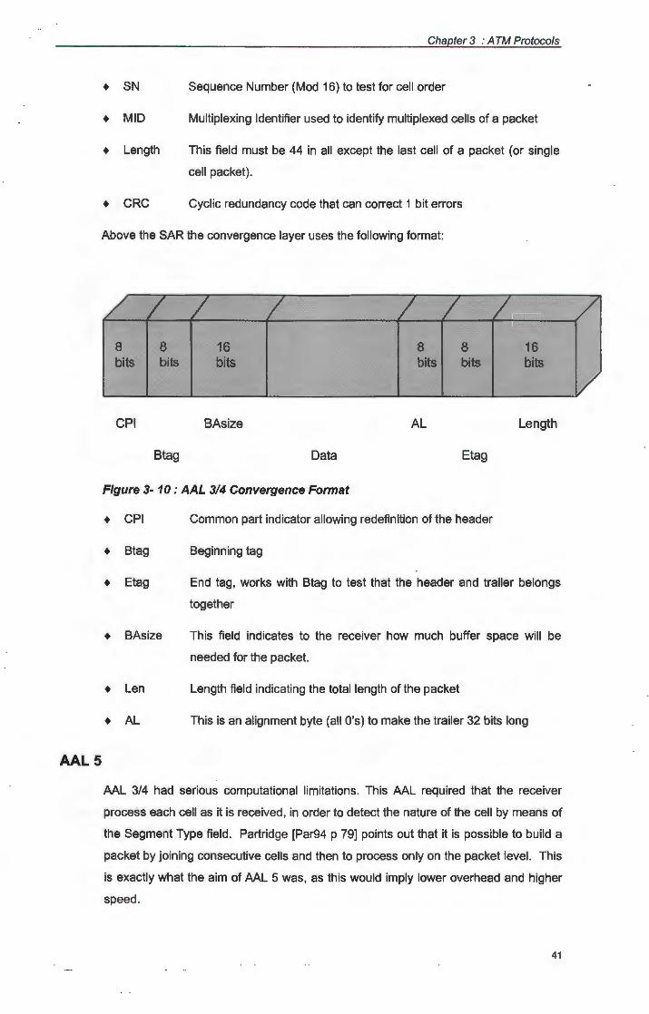
AAL5
+ SN
+ MID
• Length
+ CRC
Chapter 3 : A TM Protocols
Sequence Number (Mod 16) to test for cell order
Multiplexing Identifier used to identify multiplexed cells of a packet
This field must be 44 in all except the last cell of a packet (or single
cell packet).
Cyclic redundancy code that can correct 1 bit errors
Above the SAR the convergence layer uses the following format:
8 bits
CPI
8 bits
Btag
16 bits
BAsize
Data
8 bits
AL
8 bits
Etag
16 bits
Length
Figure 3- 10 : AAL 314 Convergence Format
+ CPI
+ Btag
+ Etag
• BAsize
• Len
+ AL
Common part indicator allowing redefinition of the header
Beginning tag
End tag, works with Btag to test that the header and trailer belongs
together
This field indicates to the receiver how much buffer space will be
needed for the packet.
Length field indicating the total length of the packet
This is an alignment byte (all O's) to make the trailer 32 bits long
AAL 3/4 had serious computational limitations. This AAL required that the receiver
process each cell as it is received, in order to detect the nature of the cell by means of
the Segment Type field. Partridge [Par94 p 79] points out that it is possible to build a
packet by joining consecutive cells and then to process only on the packet level. This
is exactly what the aim of AAL 5 was, as this would imply lower overhead and higher
speed.
41
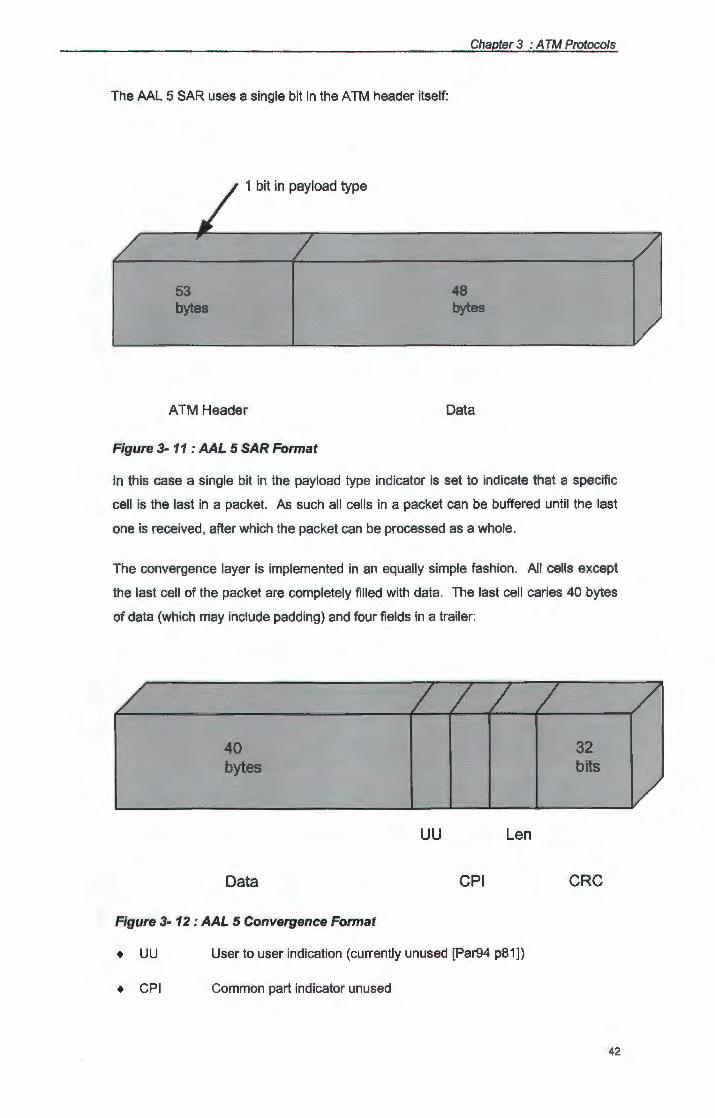
Chapter 3 : A TM Protocols
The AAL 5 SAR uses a single bit in the ATM header itself:
53 bytes
1 bit in payload type
ATM Header
Figure 3- 11 : AAL 5 SAR Format
48 bytes
Data
In this case a single bit in the payload type indicator is set to indicate that a specific
cell is the last in a packet. As such all cells in a packet can be buffered until the last
one is received , after which the packet can be processed as a whole.
The convergence layer is implemented in an equally simple fashion. All cells except
the last cell of the packet are completely filled with data. The last cell caries 40 bytes
of data {which may include padding) and four fields in a trailer:
40 bytes
Data
Figure 3- 12 : AAL 5 Convergence Format
uu Len
CPI
• uu User to user indication (currently unused [Par94 p81])
+ CPI Common part indicator unused
32 bits
CRC
42
Chapter 3 : A TM Protocols
+ Len Length of data in packet (not counting padding)
+ CRC Cyclic redundancy code, detecting lost and misordered cells
According to [Ben94 p 39] AAL 5 is particularly well suited to traffic in the current LAN
scenarios. It's buffering properties in the receiver can however still be improved, by
giving an indication of total buffer space needed {although this will once again add
complexity).
3.4. Setting up ATM connections
The previous two sections gave a broad overview of the ATM protocol definition as well as the
different functions implemented on the various layers of the ATM protocol stack. In order to
ease discussions in the next chapter, it is however necessary to look at the ATM connection
setup process.
3.4.1. ATM signaling
As mentioned earlier, ATM is connection oriented, with VPls and VCls being used to
identify the connection. Obviously this connection must be set up before it can be
used. Due to the fact that a VPI, and VCI is only unique on a per hop basis, this
connection setup must include the assignment of VPI, VCI numbers. The Quality of
Service (QoS) is also agreed upon at this stage of the connection's life time.
The QoS includes [Ben94 p 18] :
+ Desired bandwidth
+ Traffic type
+ Acceptable jitter
+ Cell loss priority
+ Acceptable delay
It is also possible to request a connection without specifying the QoS, in cases like
this the ATM network will service this connection on a "best effort" basis.
This connection setup is done by means of a separate signaling protocol. Between
the end users and the network, UNI signaling is used, while the various switches and
routers along the ATM path uses NNI signaling between themselves. After both the
destination and source user as well as the ATM network in-between, agrees to set up
a connection that fits the required QoS, a virtual connection is established. At this
stage the VPls and VCls are allocated and routing tables in the network nodes along
43
Chapter 3 : A TM Protocols
the way are updated accordingly. After this stage the various VCls and VPls may be
used to identify the connection, without involving the physical destination address en
route.
In both the case of UNI and NNI signaling an existing protocol was simply extended to
include ATM functionality. For UNI signaling the ITU Q.931 signaling standard for
Narrow band ISDN {NISDN) was extended to include:
+ Originator or distributed Point-to-Multipoint support
+ Support of symmetric operations
+ Additional traffic information parameters
+ Additional NSAP address structures
+ Re-negotiation of traffic parameters
+ Multiple connections per call
The extended signaling protocol was initially named Q.931 B but later renamed to
Q.2931.
For NNI signaling the ISUP NISDN protocol was adapted to include:
+ Channel identification
+ Cell rate specifications
+ OAM procedures
Messages sent by means of these protocols can have a number of optional fields, but
must always contain certain mandatory informational elements. These include [Pry95
p 155):
+ Connection Identifier (VPINCI pair)
+ Destination address (called party number)
+ Requested ATM cell rate
+ Requested QoS class
Optional elements can include information regarding:
+ AAL parameters
+ Calling party address
44
j
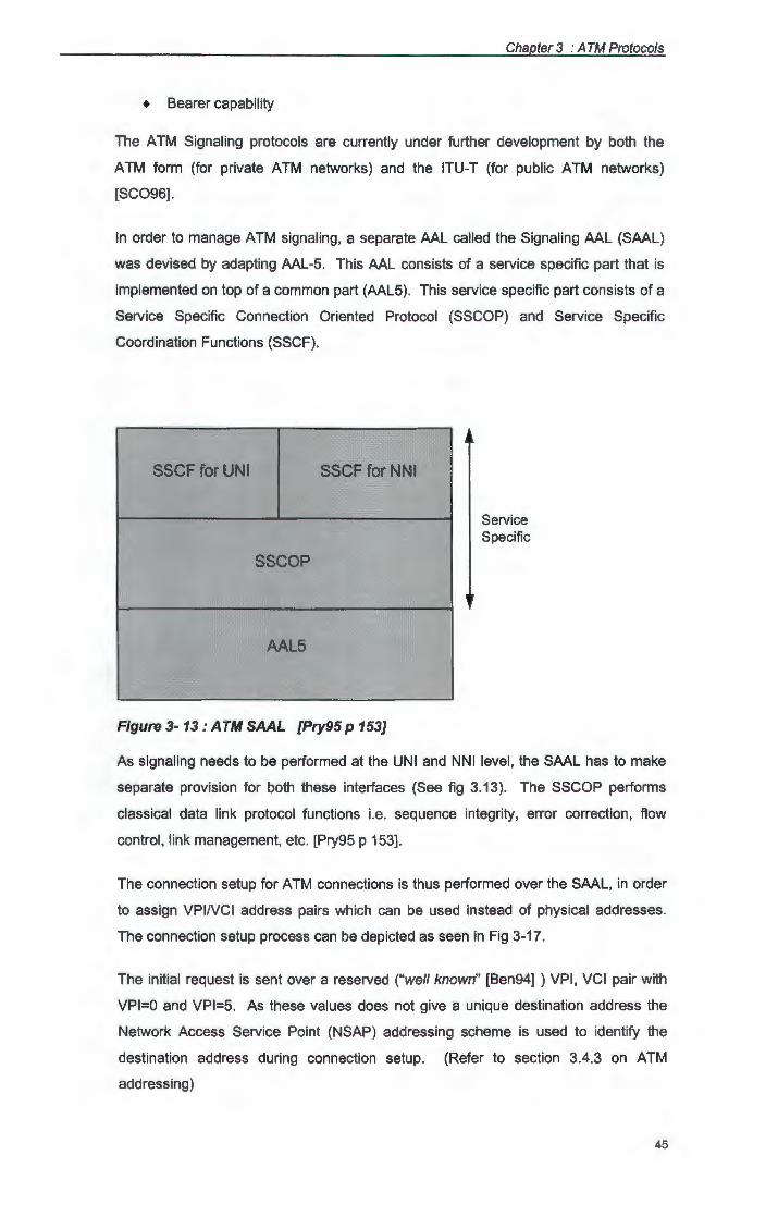
Chapter 3 : A TM Protocols
+ Bearer capability
The ATM Signaling protocols are currently under further development by both the
ATM form (for private ATM networks) and the ITU-T {for public ATM networks)
[SC096] .
In order to manage ATM signaling, a separate AAL called the Signaling AAL (SAAL)
was devised by adapting AAL-5. This AAL consists of a service specific part that is
implemented on top of a common part (AAL5). This service specific part consists of a
Service Specific Connection Oriented Protocol (SSCOP) and Service Specific
Coordination Functions (SSCF).
SSCF for UNI SSCFforNNI
SSCOP
AAL5
Figure 3- 13: ATM SAAL [Pry95 p 153]
Service Specific
As signaling needs to be performed at the UNI and NNI level, the SAAL has to make
separate provision for both these interfaces (See fig 3.13). The SSCOP performs
classical data link protocol functions i.e. sequence integrity, error correction , flow
control, link management, etc. [Pry95 p 153].
The connection setup for ATM connections is thus performed over the SAAL, in order
to assign VPINCI address pairs which can be used instead of physical addresses.
The connection setup process can be depicted as seen in Fig 3-17.
The initial request is sent over a reserved ("well known" [Ben94] ) VPI , VCI pair with
VPl=O and VPl=5. As these values does not give a unique destination address the
Network Access Service Point (NSAP) addressing scheme is used to identify the
destination address during connection setup. (Refer to section 3.4.3 on ATM
addressing)
45
Chapter 3 : A TM Protocols
3.4.2. Signaling message format
In Fig 3-14 a number of point to point signals are shown in use. In [OSC96 p 315]
several of these point to point signaling message types are identified, these include:
+ Call establishment messages
Call Proceeding: call establishment has been initiated and no
more establishment information can be added
Connect call acceptance
Connect Acknowledge Setup user has been acknowledged the call
+ Call clearing messages
Release:
Release complete:
+ Miscellaneous messages
Restart:
Restart Acknowledge:
Status Enquiry:
Status:
equipment sending the message has
disconnected the virtual connection and will next
release the VG and call reference
the VG and call reference are released and that
the VG is available to be used again
request to release all the resources associated
with the specific VG(s) controlled by the signaling
channel
response to restart to indicate completion
request a status message
response to status query, or any other time to
report certain error conditions
The format of these signaling messages is defined in [OSC96] as seen in Fig 3-14.
The various fields are used for :
+ Protocol discriminator: Used to differentiate between Q.2931 signaling and
other protocols
+ Length of Call Reference: Indicates the length of the call reference in octets.
+ Call reference: Identifies the call at the UNI.
+ Flag: Indicates at which end of the virtual signaling channel the call reference
was assigned.
46
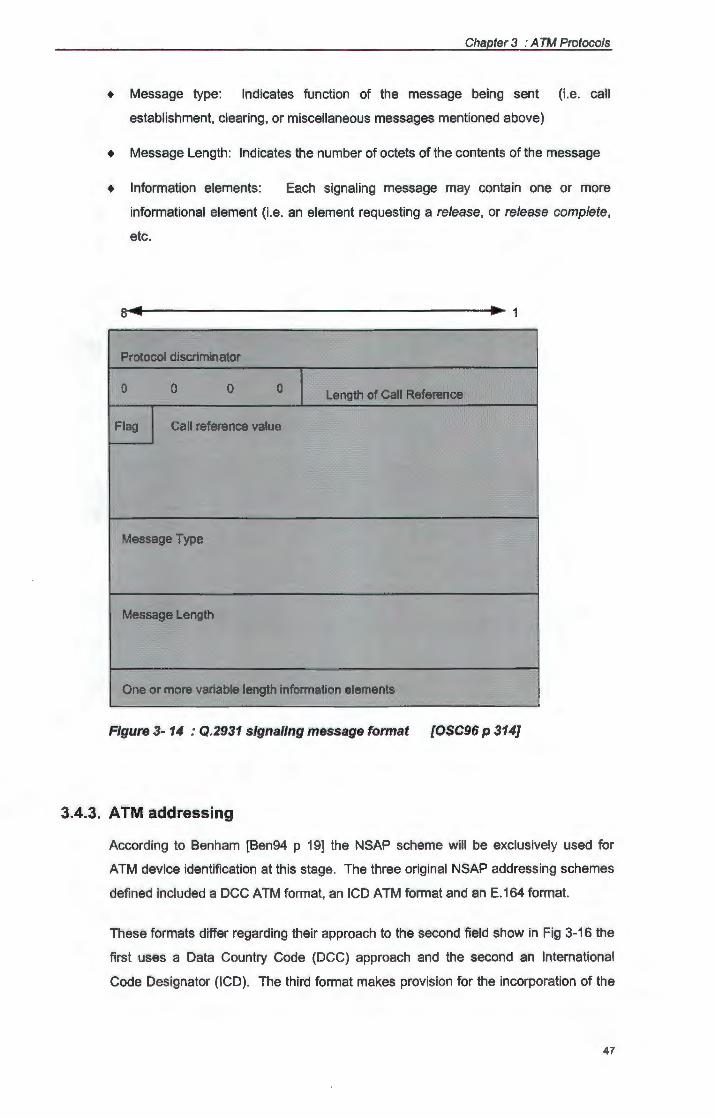
Chapter 3 : A TM Protocols
+ Message type: Indicates function of the message being sent (i.e. call
establishment, clearing, or miscellaneous messages mentioned above)
+ Message Length: Indicates the number of octets of the contents of the message
+ Information elements: Each signaling message may contain one or more
informational element (i.e. an element requesting a release , or release complete,
etc.
Protocol discriminator
0 0 0 0 Length of Call Reference
Flag Call reference value
Message Type
Message Length
One or more variable length information elements
Figure 3- 14 : Q.2931 signaling message format [OSC96 p 314]
3.4.3. ATM addressing
According to Benham [Ben94 p 19] the NSAP scheme will be exclusively used for
ATM device identification at this stage. The three original NSAP addressing schemes
defined included a DCC ATM format, an ICD ATM format and an E.164 format.
These formats differ regarding their approach to the second field show in Fig 3-16 the
first uses a Data Country Code (DCC) approach and the second an International
Code Designator (ICD). The third format makes provision for the incorporation of the
47
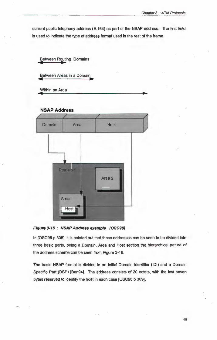
Chapter 3 : A TM Protocols
current public telephony address (E.164) as part of the NSAP address. The first field
is used to indicate the type of address format used in the rest of the frame.
Between Routing Domains ... ... Between Areas in a Domain ... ... Within an Area
NSAP Address
Domain Area Host
Figure 3-15 : NSAP Address example [OSC96]
In [OSC96 p 308] it is pointed out that these addresses can be seen to be divided into
three basic parts, being a Domain, Area and Host section the hierarchical nature of
the address scheme can be seen from Figure 3-16.
The basic NSAP format is divided in an Initial Domain Identifier (IOI) and a Domain
Specific Part (DSP) [Ben94]. The address consists of 20 octets, with the last seven
bytes reserved to identify the host in each case [OSC96 p 309].
48
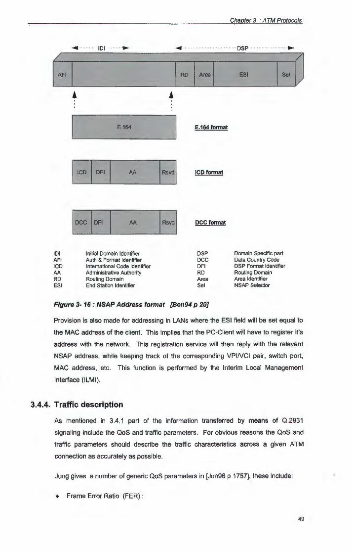
IOI AFI ICD AA RD ESI
IOI .. ....
E.164
AA
AA
Initial Domain Identifier Auth & Format Identifier International Code Identifier Administrative Authority Routing Domain End Station Identifier
E.164 format
ICD format
DCC format
DSP DCC DFI RD Area Sel
Figure 3- 16: NSAP Address format [Ben94 p 20]
Chapter 3 : A TM Protocols
DSP
ESI
Domain Specific part Data Country Code DSP Format Identifier Routing Domain Area Identifier NSAP Selector
....
Provision is also made for addressing in LANs where the ESI field will be set equal to
the MAC address of the client. This implies that the PC-Client will have to register it's
address with the network. This registration service will then reply with the relevant
NSAP address, while keeping track of the corresponding VPINCI pair, switch port,
MAC address, etc. This function is performed by the Interim Local Management
Interface (ILMI).
3.4.4. Traffic description
As mentioned in 3.4.1 part of the information transferred by means of Q.2931
signaling include the QoS and traffic parameters. For obvious reasons the QoS and
traffic parameters should describe the traffic characteristics across a given ATM
connection as accurately as possible.
Jung gives a number of generic QoS parameters in [Jun96 p 1757], these include:
+ Frame Error Ratio (FER) :
49
Chapter 3 : A TM Protocols
This parameter refers to the amount (percentage) of frames received errored at
the AAL layer. With FER max defined such that
FER ~FER max and
FER = errored_frames I total_frames
+ Throughput Bound (W) :
This parameter refers to the throughput of a connection, indicating a measure of
the bit rate attainable by the connection at the AAL layer. Jung indicates that W
min can be defined by the AAL as part of the QoS such that:
W .'.:: Wmin
for all different network layers along the connection path. This specifies a lower
bound to the throughput.
+ Frame Delay Bound (D max)
This parameter refers to the delay with which a frame is delivered to the
destination (at the AAL layer) for instance the i th frame is delivered in delay D;
with
D; ~ Dmax for all i
+ Frame Delay Variation (Jitter) Bound (J max)
This parameter refers to the variance in delay D; with
(J; = I Di - D I ) ~ J max for all i
J; is the Jitter of the i th frame when delivered to the destination.
+ Cell Loss Ratio (CLR) :
This parameter refers to the ratio of cells lost at the ATM layer according to Jung it
results mainly from buffer overflow in ATM switches due to congestion.
+ Cell Missinsertion Rate (CMR) Bound:
This parameter refers to the cells lost due to error(s) in the ATM header. Normally
the CMR can be considered negligible compared to the CLR. Jung attributes this
to the ability of ATM switches to detect and discard cells with errored headers.
In addition to these [OSC96 p 310] also mentions:
50
Chapter 3 : A TM Protocols
+ Peak Cell Rate (PCR) :
The maximum cell rate a source can handle.
• Sustainable Cell Rate (SCR) :
The maximum cell rate a source can handle over an indefinite period of time.
+ Burst Tolerance:
An indication of a node's sensitivity to bursty traffic.
It is clear that the use of the above traffic and QoS descriptors should allow for a detail
description of the expected traffic characteristics of a given ATM connection. These
parameters can clearly be used for routing in an ATM network during connection
setup. It must be noted however that the accuracy of these parameters will have an
influence on traffic circumstances along the route (i.e. possible congestion or under
utilization of a link).
3.4.5. Route selection
According to Benahm [Ben94 p 22] the Private Network to Network Interface (P-NNI)
routing protocol will be used for route selection. He further indicates that at it's fully
developed stage, this protocol will contain attributes of the Open Shortest Path First
(OSPF), Intermediate System to Intermediate System (IS-IS}, Border Gateway
Protocol (BGP) and Inter Domain Routing Protocol (IDRP) protocols. Most of these
protocols have been in operation for some time in TCP/IP environments in WANs and
the Internet.
In most of the protocols mentioned above the cost (number of hops) is used as the
primary metric for the selection of a route from a number of nodes. Due to the service
guarantees build into ATM the normal route calculations will have to be adapted in
order to select the route based on the QoS as a whole. This will imply that these
calculations will have to include link and endpoint metrics in their parameters.
Benham gives the minimum metrics exchanged by P-NNI Routing protocols as:
• Cost (Hops)
+ Link capacity and constraints
+ Propagation delay
• Cell delay (Latency)
51
Chapter 3 : A TM Protocols
• Cell delay variance (Jitter)
+ Current sustained capacity
Of these parameters the first three can be seen as static, while the last three should
be considered dynamic in nature.
In [Ben94 p 22] it is pointed out that these additional metrics will complicate ATM route
selection, but that due the fact, that the route is only selected once (during connection
setup) a lower routing overhead than in today's IP networks can still be expected.
3.4.6. Connection setup sequence
With the above discussion in mind we are now in a position to give the steps used to
set up an ATM point-to-point connection by means of Q.2931 signaling. Given a
source terminal (A) and a destination terminal (B) as indicated in Fig 3-17, Onvural
indicate the setup process at the UNI to consist of the following [OSC96 p 317] :
+ A sends a SETUP message to the network node it is attached to. This message
contains the address details of the end station B (NSAP address as discussed in
par 3.4.3) as well as the connection characteristics (as discussed in 3.4.4) and
other detail (listed in par 3.4.1) for the compulsory and optional setup signal fields.
+ The network node replies to A by sending a CALL PROCEEDING message,
indicating that it has received the SETUP message and is busy with the rest of the
connection setup. At this stage, part of the CALL PROCEEDING MESSAGE also
supplies A with a VPINCI pair.
+ The network will now forward the SETUP message to the node to which B is
attached, using P-NNI route selection based on QoS and traffic parameters (as
discussed in par 3.4.5).
+ The network then delivers the SETUP message to B, also issuing B a VPINCI
pair for future use between Band it's node for that particular connection.
+ If B decides to accept the connection, it will return a CONNECT message to its
network node.
+ The network node will then send a CONNECT ACKNOWLEDGE message to B
and forward B's CONNECT message information to A's network node.
• The network node at A sends a CONNECT message to A after receiving the
connect acknowledge information from B's node.
52
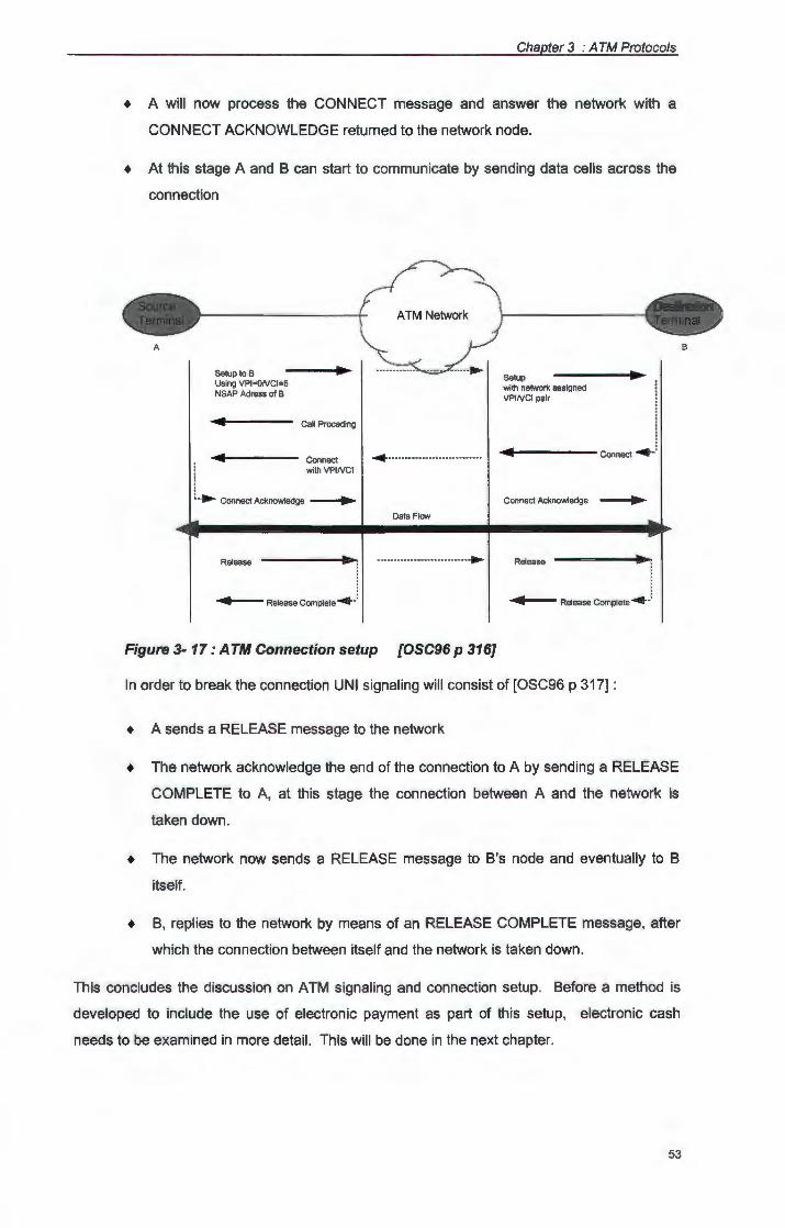
Chapter 3 : A TM Protocols
• A will now process the CONNECT message and answer the network with a
CONNECT ACKNOWLEDGE returned to the network node.
+ At this stage A and B can start to communicate by sending data cells across the
connection
A
Setup to B .. Using VPl=ONCl=5 NSAP Adress of B
4 Call Proceding
Connect withVPINCI
~ • ._ Connect Acknowledge --.. ~
~····· · ·· · · · ·· · · ·· · ···· · ·· · ··
Data Flow
Release ... .. .. .. .. ... . . . . . . . . .. . ... ....
4 Release Complete ....... :
Figure 3- 17: ATM Connection setup [OSC96 p 316]
Setup with networ1< assigned VPINCI pair
-4'----- connect ....... :
Connect Acknowledge ..
Release
4 Release Complete~·:
In order to break the connection UNI signaling will consist of [OSC96 p 317] :
+ A sends a RELEASE message to the network
+ The network acknowledge the end of the connection to A by sending a RELEASE
COMPLETE to A, at this stage the connection between A and the network is
taken down.
+ The network now sends a RELEASE message to B's node and eventually to B
itself.
• B, replies to the network by means of an RELEASE COMPLETE message, after
which the connection between itself and the network is taken down.
This concludes the discussion on ATM signaling and connection setup. Before a method is
developed to include the use of electronic payment as part of this setup, electronic cash
needs to be examined in more detail. This will be done in the next chapter.
53
B
Chapter 3 : A TM Protocols
3.5. Summary
This chapter took a closer look at ATM, as well as the definition thereof. The discussion
included the different layers of the ATM implementation and indicated the various sub
protocols operating at each layer. Closer attention was also paid to the functions of each of
these layers. The chapter concluded with a section indicating the signaling, addressing and
routing necessary for ATM connection setup, as well as a summary of the messages sent
during setup.
54
Chapter 4
Electronic Payment
4.1. Introduction
In this chapter various electronic payment techniques are discussed. Due to the fact that the
understanding of Ecash is one of the main objectives of this study special reference is made
to the use of electronic cash. In order to better understand the electronic cash payment
system discussed here, it is also necessary to look at the definition (and requirements) of a
payment system in general. As a matter of fact, electronic cash can be seen as just another
evolutionary development of payment systems in general. This is especially clear when a
closer look is taken at the background and development of the various electronic payment
methods.
4.2. Background
In an age of credit cards, automatic teller machines and banking computers, the idea of
electronic payments is not a new one. Until recently however, it was accepted that these
transactions will take place between individuals and I or organizations that must have each
other's account details. This obviously also implies that such a person must have an account,
with a bank or other organization in order to participate.
Although there are cases where these types of electronic transactions will be acceptable and
sufficient, they may allow certain negative aspects to be explored if used for payment over
open networks (like the Internet). For instance it will be possible to trace and set up a dossier
on an individual's spending habits, rendering electronic privacy obsolete. Furthermore the fact
that the client must have an account with the supplier, limits the availability of this method (to
those with accounts) and also adds cost (i.e. admin, and billing costs).
One method to overcome the above problems is to visit the supplier in person and to pay in
cash, this is however only practical when the service provider and client are in the same
geographical area. With the advent of trading over the Internet these problems became even
more prominent. This lead to the development of various other methods of handling electronic
payment (including various forms of electronic I digital cash) which were progressively more
and more network based.
Chapter 4 : Electronic Payment
4.3. Development history of network based cash electronic payments
As mentioned above, the idea of sending money across a communication network has been in
use in the banking environment for some time. However, it has always been limited to
transactions between parties, which have each other's account details. As such, these
transactions could not truly be compared to a "real world" cash transaction. To a certain
extent the development history of network based cash electronic payments has its roots in the
Internet and can be said to be motivated, in a large degree, by trading possibilities on the
Internet.
According to [DigMon] the use of money on the Internet went through a number of
evolutionary phases:
4.3.1. External Payments
The first payments for services on the Internet were conventional ones external to the
Internet itself. Subscribers transfer monthly amounts from their bank accounts to that
of the service provider. These payments would obviously be expensive and also take
a long time to process, especially when the transfer is from one country to the other.
([Smu95] points out the drawbacks of a scheme where use of a service and payment
thereof is not closely linked in time.) It should be obvious that this scheme is not really
suited to one time payments, although it could work for long term relations. (The
payment of CompuServe services in the RSA is an example of such a scheme.)
4.3.2. Payments using credit card details
The next possibility was thus to use payment by credit card. The client would simply
include his credit card details in the order to the service provider. The credit
organization will then handle this payment like any normal transaction. Although this
method makes payment much easier it does have certain drawbacks:
+ It is insecure, the client's credit card details are sent in an open message across
an open network. As such it can be intercepted and used for fraudulent
withdrawals on the client's account. It is also possible for an external party to
track an individual's spending habits by keeping track of messages that includes
his credit card number.
+ It costs money, as such the credit card transaction may be more expensive than
certain low cost network transactions.
56
Chapter 4 : Electronic Payment
4.3.3. Payments using encrypted credit card details
Taking the above into consideration, it is no surprise that the use of encrypted credit
card details was the next step in the evolutionary process. This method took care of
the security problem, but still leaves the problem of overhead costs when dealing with
small amounts. As in the case of external payments (4.3.1.) there are certain cases
where this method will however be sufficient.
4.3.4. Payments using third parties
In order to solve the problem of overhead costs, one solution would be to introduce a
third party. This third party would typically be a company that collects and approves
payments from one client to the other. After a certain period of time a single credit
card transaction can then be done for the total amount of these smaller transactions.
Once again this solution is not optimal, for instance:
+ Who pays the third party? This means more overhead costs.
+ Payments may be refused due to a credit limit being reached, before the single
large credit card transaction is done.
+ Once again the spending profile of a client is readily available, and kept in a
central place (at the third party).
4.3.5. Payments using ecash
These, and other problems lead to the development of smart cards as described in
[Cha92]. These systems consist of a tamper proof, card based chip, that can be seen
as the electronic equivalent of a purse. The original systems had the same drawback
as cash, the client, service provider and smart card had to be in the same shop.
However, it did not take long for the first software only, systems to be developed (i.e.
Cyberbucks or Digicash's ecash system).
+ These systems have the same advantages as conventional cash, but it negates
some of the problems of conventional cash. (For instance immediate ecash
payments over great distances is now possible.)
4.4. What is payment?
Although the word payment is mentioned quite often in everyday life, it may ease the
discussion in the rest of this chapter if we can formalize it's intended meaning within the scope
of this thesis. For the purpose of this study payment can thus be defined as:
57

Chapter 4 : Electronic Payment
The transfer (from client to service provider) of a token which directly or indirectly
constitutes a value in some monetary system.
As such, any payment system will need some form of token as well as some kind of transfer
process, in order to function. In certain cases a verification method is also needed, in order to
check that a token does indeed constitute the claimed monetary value. Referring back to the
development history discussed in par 4.3, it can be seen that this is indeed the case in all the
payment systems developed to date.
4.5. Requirements of a payment system
As seen in par 4.3, the development of new payment systems often takes place due to a
perceived lack in the existing methods (i.e. the lack of privacy that prompted the development
of Ecash). In general a payment system should thus meet certain requirements in order to
succeed:
+ Tokens must constitute value in some monetary system;
+ It must be possible for a receiver to verify the value of a token;
+ Tokens must be transferable from one owner to another;
+ The transfer of tokens must be secure;
+ It must not be possible to generate tokens without having it backed by monetary
value, (as such the counterfeit or double spending of tokens should not be possible).
It is possible to define various payment techniques that will enable a payment system to
satisfy the above requirements. Such techniques can be broadly divided into two categories,
being electronic and non electronic payment techniques.
4.6. Non-electronic payment techniques
Various non-electronic payment systems have been developed to date. For the purpose of
this study a non electronic payment system can be defined as a system using:
+ non-electronic tokens;
+ a non-electronic or electronic transfer method;
+ a non-electronic or electronic method of verification.
58
Chapter 4 : Electronic Payment
4.6.1. Cash payments
This form of payment constitutes the use of currency as token, often with the issuing
country's gold reserve backing the paper or coin form of token. It is easy to see that
this system does indeed satisfy the above requirements of a payment system.
Conventional cash can furthermore be considered to possess certain characteristics,
for instance [Smu95] indicates that:
+ cash can be accepted on face value;
+ cash is normally not traceable and thus provides anonymity;
+ payment by cash does not incur an overhead cost.
As such it is possible for the client to pay by cash, without having to consider an
overhead fee, while the service provider does not need to check the client's
credentials before accepting the payment. Furthermore it is also possible to grant a
measure of privacy due to the intractability of the transaction.
4.6.2. Cheques
Payment by cheque normally consist of a note written by the payer, giving the bank
authorization to debit his own account and credit that of the service provider. In this
case the signed note acts as a token. This token is assumed to be backed by
currency available in the payer's account.
Once again certain characteristics can be attributed to this payment system:
+ cheques can not be accepted on face value (the bank can still refuse payment if
the payee does not have sufficient funds in his/her account);
+ unlike cash, a cheque needs to be signed by the spender before it represents
value;
+ a cheque can represent an exact amount (as such it is not necessary to build up
the required value by means of a number of cheques, as is the case with cash
notes);
+ at least one of the parties in question (the payer), must have an account with the
bank who's cheque is used as payment;
+ due to the above, cheques are traceable and thus does not provide anonymity;
+ payment by cheque does incur an overhead cost for the payer.
59
\

Chapter 4 : Electronic Payment
4.6.3. Money Orders and Bearer Bonds
This form of payment uses a token which consist of a note backed by (normally} a
government's currency. Payment is guaranteed and can be done directly to the
bearer.
Characteristics that can be attributed to this payment system includes:
• money orders can be accepted on face value;
+ none of the parties in question needs an account with an financial institution;
+ money orders does provide anonymity;
4.7. Electronic payment techniques
In most cases electronic counterparts have been developed for each of the various non
electronic payment systems developed to date. For the purpose of this study an electronic
payment system can be defined as a system using:
• electronic tokens;
+ an electronic transfer method;
+ an electronic method of verification (when applicable}.
4. 7 .1. Electronic fund transfers
This kind of payment system uses electronic means to transfer an electronic
representation of currency from one account to the other. (This is the oldest of the
electronic methods discussed here, having been in use for a number of years in the
banking industry.)
Characteristics of this system includes:
+ both parties involved needs an account of one kind or the other;
+ payment is guaranteed after successful completion of the transaction;
+ electronic transfers does not provide anonymity;
+ electronic transfers do have overhead costs.
4.7.2. Credit Cards
In this case a third party (the credit organization) undertakes to pay accounts on
behalf of the payer in return for a monthly lump sum payment by the payer. Electronic
60
Chapter 4 : Electronic Payment
representation of currency is used as tokens with the transfer taking place
electronically. Verification can be either by means of a signature (non-electronic) or
purely electronic. (Making this system a hybrid system in terms of our definition of an
electronic payment system.)
In this case the characteristics of the payment system includes:
+ at least one of the parties involved needs an account with the credit organization;
+ payment can be refused due to insufficient credit in the payer's account;
+ credit cards does not provide anonymity for either party;
+ the use of credit cards does incur an overhead cost.
4. 7 .3. Electronic cash
Electronic cash (ecash) uses electronic tokens transferred in an electronic means to
enable payment. These tokens represent a monetary value in themselves and do not
simply act as an electronic cheque that promises payment at a later stage.
Like the previous systems mentioned we would expect ecash to have certain
characteristics. According to [Sch94, p 123] these must include:
+ Independence, the security of ecash is not dependent on a specific physical
location;
+ Security, ecash can not be copied and reused;
+ Privacy, the privacy of users is protected, the transaction is not traceable
between user and point of purchase;
+ Off-Line Payment, when a user pays using ecash, it must be possible to complete
the protocol between the shop and the user off-line;
+ Transferability, ecash is transferable between users, and not just between a user
and a bank or merchant;
+ Divisibility, it is possible to divide an ecash note into smaller denominations with
the same total value.
When considering these characteristics, it should be clear why ecash can be seen as
the electronic equivalent of normal cash.
61
Chapter 4 : Electronic Payment
+ ecash is versatile, it can be used for on-line payments over the phone, to handle road
toll payments automatically (without the need to stop) or to buy goods directly over the
counter;
+ ecash is secure, due to its unique digital signature it can not be spent more than once
and is signed by the bank as acceptable cash even before it is issued;
+ ecash is private, it makes it impossible to connect payment and payer while still
allowing the user to prove that payment was made.
That leaves the question, what's in it for the service provider (or for that matter the Internet
shop)? From this point of view, the above mentioned advantages still holds, however in
addition to these the following can also be to their advantage:
+ payment is immediate, increasing cash flow;
+ payment is guaranteed when checked on-line with the bank (the need to check can
also be seen as an disadvantage);
+ administration overheads are limited.
As with most things in life ecash has it's negative points as well. In [Sch94] it is pointed out
that ecash's privacy can be used to engineer the perfect anonymous crime. Furthermore, due
to the electronic nature of ecash it can be adversely influenced by hard disk crashes,
unavailable network links, etc.
Keeping our aim with the use of Ecash (payment of network services) in mind, a serious
drawback is that double spending during offline transactions can at most be detected, but not
prevented.
Another disadvantage to ecash is that it does require a high technology infrastructure in order
to be used. For the purpose of this study however this can be ignored as the same
infrastructure is taken for granted in the network environment for which we aim to develop a
payment scheme.
4.13. Summary
This chapter introduced the concept of electronic cash, as money that is represented by
numbers. The characteristics of ecash were discussed and compared with that of normal
cash. An overview of a general ecash transaction was given after which the techniques used
in the ecash protocols were discussed. Finally an ecash protocol was presented, and an
74

Chapter 4 : Electronic Payment
example given to indicate how a transaction between a payer, a service provider and the bank
should take place.
75
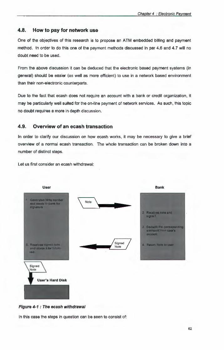
Chapter 4 : Electronic Payment
4.8. How to pay for network use
One of the objectives of this research is to propose an ATM embedded billing and payment
method. In order to do this one of the payment methods discussed in par 4.6 and 4.7 will no
doubt need to be used.
From the above discussion it can be deduced that the electronic based payment systems (in
general} should be easier (as well as more efficient) to use in a network based environment
than their non-electronic counterparts .
Due to the fact that ecash does not require an account with a bank or credit organization, it
may be particularly well suited for the on-line payment of network services. As such, this topic
no doubt requires a more in depth discussion.
4.9. Overview of an ecash transaction
In order to clarify our discussion on how ecash works, it may be necessary to give a brief
overview of a normal ecash transaction. The whole transaction can be broken down into a
number of distinct steps.
Let us first consider an ecash withdrawal:
User Bank
•
•
Figure 4-1 : The ecash withdrawal
In this case the steps in question can be seen to consist of:
62
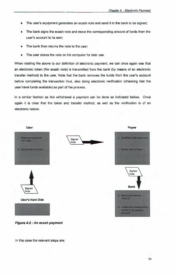
Chapter 4 : Electronic Payment
+ The user's equipment generates an ecash note and send it to the bank to be signed;
+ The bank signs the ecash note and move the corresponding amount of funds from the
user's account to its own;
+ The bank then returns the note to the user;
+ The user stores the note on his computer for later use.
When relating the above to our definition of electronic payment, we can once again see that
an electronic token (the ecash note) is transmitted from the bank (by means of an electronic
transfer method} to the user. Note that the bank removes the funds from the user's account
before completing the transaction thus, also doing electronic verification (checking that the
user have funds available} as part of the process.
In a similar fashion as this withdrawal a payment can be done as indicated bellow. Once
again it is clear that the token and transfer method, as well as the verification is of an
electronic nature.
User
Signed Note
User's Hard Disk
Figure 4-2 : An ecash payment
In this case the relevant steps are:
Payee
•
63
Chapter 4 : Electronic Payment
+ The user retrieves the note from his hard drive and sends it to the payee
+ The payee checks that the note's digital signature is authentic and sends it on to the
bank;
+ The bank checks the digital signature and credits the payee to the according amount.
4.10. How ecash works
The above discussion gives an overview of an ecash transaction, without going into ecash in
detail. In our definition of payment (in par 4.4) a token, a transfer method and a verification
method was mentioned. In order to understand ecash, it is necessary to look closer at these
terms within the ecash environment.
Due to the electronic nature of ecash, it's environment can be expected to be electronic as
well. In order to function ecash will need an infrastructure consisting of:
+ a communication system to enable transfers of electronic tokens;
+ a computer or smart card in order to manipulate and store these tokens;
+ a software system in order to do verification and validation on the tokens.
The communication system on which ecash is implemented is normally network based. As
various forms of network systems has been mentioned in the previous chapters, only the
electronic representation and verification of tokens need further discussion. Due to the fact
that the verification of ecash tokens forms an integral part of the representation of such
tokens, these two facets should not be discussed under separate headings. Instead, the
underlying principles of ecash's representation and verification are discussed first, after which
we will be in a position to discuss a general ecash protocol.
4.10.1.The electronic representation of ecash tokens
Ecash is represented by a digital note consisting basically of a random number
generated by the user's or bank's computer. This token also indicates the note's
value and authenticity while at the same time maintaining privacy.
In order to indicate it's authenticity the note must contain a digital signature from the
bank which guarantees it's payment. This can be done by encrypting the digital note's
number by means of an RSA encryption system, with the bank holding the private
key.
To preserve privacy it is necessary for the note to carry a blinding factor when sent to
the bank for signing. This can be done by the user by simply multiplying the note
64
Chapter 4 : Electronic Payment
number by a random number before presenting it to be signed, and dividing it by the
same number after the signature has been applied.
Due to the digital nature of ecash, it can be copied. To stop users from spending the
same note twice a set of identity strings will also have to be included in the note
structure. (These strings will give away a user's identity as soon as he tries to spend
the same note the second time.)
As in the case of normal cash the note should also carry an indication of it's value.
This can be stored as a separate field or it can be encoded as part of the bank's
signature.
In order to clarify these different components of an ecash note, each of them is
discussed in more detail in the following sections.
4.10.2.What is a digital signature
The aim of a signature is to provide a means by which a message can be
authenticated. This also holds true for a digital signature, but a digital signature goes
further by also indicating that the message has not been changed en route, prior to
delivery.
A digital signature is defined by [DigSig] as a small amount of data that is recorded on
an electronic medium. This signature is produced by the sender by applying a certain
calculation to the message. This calculation is called the 'signature function'. The
resulting signature, which looks like random data, will only have meaning when read in
conjunction with the message (in the case of ecash, the note number) used to create
it. The recipient of the message checks this signature by performing another set of
calculations (called the 'verification function') on the signature and the message. The
outcome of these calculations reveals whether or not the signature is a genuine and
thus also authenticates both the sender and the message.
It is possible to use either secret or public key encryption methods to affect the
signature mentioned above. However, the use of a secret key system is not really
suitable to payments over an open network. This is due to security risks involved,
when both the sender and the receiver must know the secret key.
65
Chapter 4 : Electronic Payment
4.10.3.Digital signatures by means of RSA encryption
When RSA public/private key functions is used, it is possible to let the receiver know
the public key, without revealing the private key and thus to maintain a higher level of
security.
One such method is described by [DigNum] as a system where the note number is
raised to a power that corresponds to the appropriate key. Further more these
exponentiations will be done in a modular arithmetic system where only the result of a
modular division is stored. It is also recommended that the modules should be a
sufficiently large number, at least 150 digits long.
To start with the sender (in this case the digital bank) generates two large primes p
and q. The encryption algorithm is based on the fact that
x<P-1Hq-1J = 1 (mod pq)
The next step for the bank is to choose an e and d so that
ed = 1(mod pq)
where e will be the public and d the private key. As such it will be possible to decrypt
anything encrypted by d by using e due to the fact that :
(X'1)• = x (mod pq)
Also note that the receiver can not deduce d (which the bank obviously keeps secret)
without knowing p and q even though he does know pq and e, due to the many to
one nature of the relationship above.
Taking the above into consideration it is possible for an ecash bank to use digital
signatures as follows:
+ To get a note signed the user presents the bank with x • (mod pq) where x
represents the note number.
+ The bank signs this by raising it to the power d that is (x • ) d and returns it to
the user.
+ The user receives (x •) d as x d (mod pq) and stores x d (which he/she can
compute knowing pq) as the note to pay with.
66
Chapter 4 : Electronic Payment
4.10.4.Blind signatures
Due to the fact that the bank, can compute x (knowing the precise value of cl}, it will be
possible for the bank to store the note numbers and as such to build up a spending
profile for a particular user. In order to negate this possibility blind signatures are
introduced.
This implies that the bank will sign a note without knowing the true note number, while
still keeping the ability to recognize it's own signature at a later stage (i.e. when the
note is presented as payment).
In order to achieve this, the user generates the note number (not the bank) and then
multiply the note number by a blinding factor r. After the note is signed, the user
simply divides out the blinding factor to get his original, but signed, note.
This means that the signing process described above will then change to:
+ The user chooses a random blinding factor r.
+ The user presents the bank with rx• (mod pq) where x once again represents
the note number.
+ The bank signs this by raising it to the power d that is (xr•) d and returns it to
the user.
+ The user receives (xr• )d as rxd (mod pq) and divides out r.
+ Finally the user stores xd as the note to pay with.
This scheme adds an important extension to ecash's digital signature, being that of
payer anonymity. Except for this privacy, it also enables the user to prove that a
payment was done, by revealing the blinding factor (which is only known to him/her).
4.10.5.lndicating a notes value
In his article On-line Cash Checks [DigChk], Chaum shows how the exponents in an
RSA encryption system can be used to indicate an electronic note's value. It is easier
to show how this can be done by means of an example, rather than a pure factual
discussion.
In Chaum's scheme the odd prime exponents are used to indicate 1 's in the
corresponding position of a binary representation. This can be done by representing
each successive power of two value by a corresponding odd prime root in the RSA
system, all with the same modulus. In his example in [DigChk] he shows how the
67

Chapter 4 : Electronic Payment
(arbitrary) value of 1 cent can be assigned to the public exponent three, that of 2 cents
to exponent five, 4 cents to exponent seven, etc.
15c
t Monatary Value
Binary
RSA
Figure 4-3 : Converting RSA exponents to Monetary Value
Keeping in mind the above discussions on blind signatures and an ecash note being
represented as simply a number, consider the case where the user want's to withdraw
15 cents from the bank (assume that above allocations to cent values are used):
+ let the note number generated by the user's equipment be n;
+ let the blinding factor be r;
+ let the bank sign by taking the h-th root;
+ let f be an one way RSA public key encryption function
As such the user will choose n and r and start communicating with the bank. This
communication will consist of a two way process:
+ the user will present the bank with f(n) * r h in this case : f(n) * r r3•5 '7'11;
+ the bank will answer with f(n) * r 1/h in this case : f(n) * r 11r3 '5"7'11J
This scheme holds a number of advantages. Not only is the note's value an integral
part of the signature but it is also relatively easy to devaluate, thus enabling partial
68
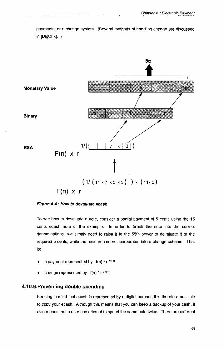
Chapter 4 : Electronic Payment
payments, or a change system. (Several methods of handling change are discussed
in [DigChk]. )
Sc
t Monatary Value
Binary
RSA 1/( ~~~~~~~----'
F(n) x r
t {1/{11x7x5x3} }x{11x5}
F(n) x r
Figure 4-4 : How to deva/uate ecash
To see how to devaluate a note, consider a partial payment of 5 cents using the 15
cents ecash note in the example. In order to break the note into the correct
denominations we simply need to raise it to the 55th power to devaluate it to the
required 5 cents, while the residue can be incorporated into a change scheme. That
is:
+ a payment represented by f(n) * r 11r3?J
+ change represented by f(n) * r 11r5•11J
4.10.6.Preventing double spending
Keeping in mind that ecash is represented by a digital number, it is therefore possible
to copy your ecash. Although this means that you can keep a backup of your cash, it
also means that a user can attempt to spend the same note twice. There are different
69
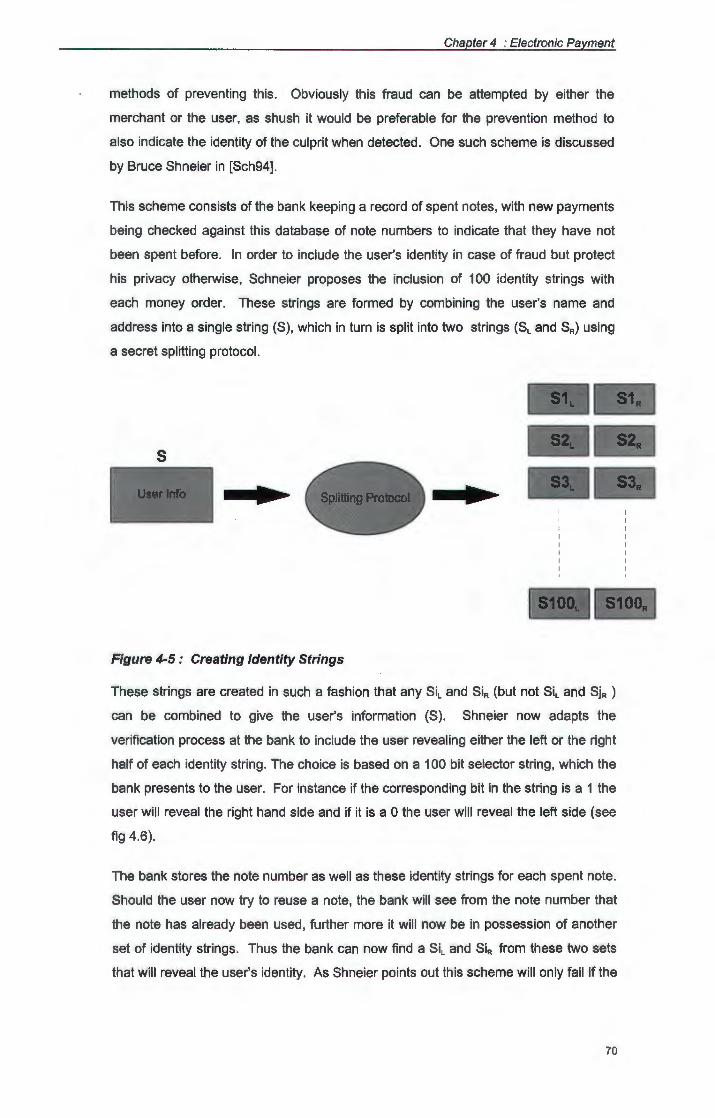
Chapter 4 : Electronic Payment
methods of preventing this. Obviously this fraud can be attempted by either the
merchant or the user, as shush it would be preferable for the prevention method to
also indicate the identity of the culprit when detected. One such scheme is discussed
by Bruce Shneier in [Sch94].
This scheme consists of the bank keeping a record of spent notes, with new payments
being checked against this database of note numbers to indicate that they have not
been spent before. In order to include the user's identity in case of fraud but protect
his privacy otherwise, Schneier proposes the inclusion of 100 identity strings with
each money order. These strings are formed by combining the user's name and
address into a single string (S), which in turn is split into two strings (SL and SR) using
a secret splitting protocol.
s
• • -
Figure 4-5 : Creating Identity Strings
These strings are created in such a fashion that any Sil and SiR {but not Sil and SjR )
can be combined to give the user's information (S). Shneier now adapts the
verification process at the bank to include the user revealing either the left or the right
half of each identity string. The choice is based on a 100 bit selector string, which the
bank presents to the user. For instance if the corresponding bit in the string is a 1 the
user will reveal the right hand side and if it is a 0 the user will reveal the left side (see
fig 4.6).
The bank stores the note number as well as these identity strings for each spent note.
Should the user now try to reuse a note, the bank will see from the note number that
the note has already been used, further more it will now be in possession of another
set of identity strings. Thus the bank can now find a Sil and SiR from these two sets
that will reveal the user's identity. As Shneier points out this scheme will only fail if the
70
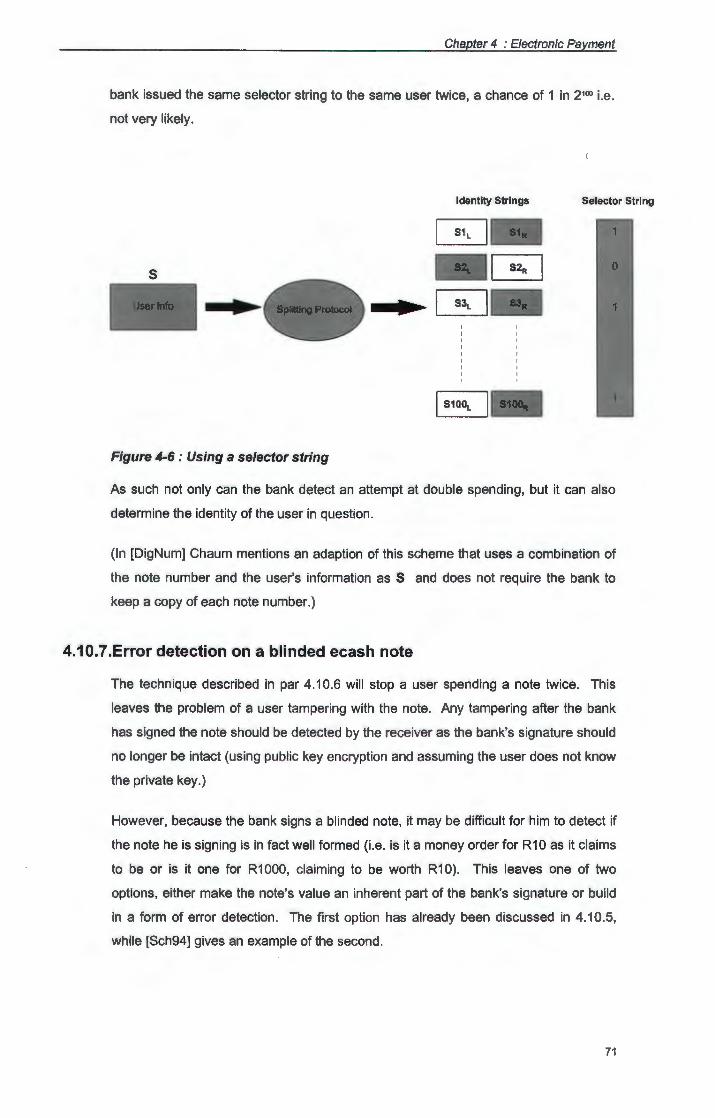
Chapter 4 : Electronic Payment
bank issued the same selector string to the same user twice, a chance of 1 in 2100 i.e.
not very likely.
Identity Strings Selector String
s
• •
~-Figure 4-6 : Using a selector string
As such not only can the bank detect an attempt at double spending, but it can also
determine the identity of the user in question.
(In [DigNum] Chaum mentions an adaption of this scheme that uses a combination of
the note number and the user's information as S and does not require the bank to
keep a copy of each note number.)
4.10.7.Error detection on a blinded ecash note
The technique described in par 4.10.6 will stop a user spending a note twice. This
leaves the problem of a user tampering with the note. Any tampering after the bank
has signed the note should be detected by the receiver as the bank's signature should
no longer be intact (using public key encryption and assuming the user does not know
the private key.)
However, because the bank signs a blinded note, it may be difficult for him to detect if
the note he is signing is in fact well formed (i.e. is it a money order for R10 as it claims
to be or is it one for R1000, claiming to be worth R10). This leaves one of two
options, either make the note's value an inherent part of the bank's signature or build
in a form of error detection. The first option has already been discussed in 4.10.5,
while [Sch94] gives an example of the second.
71
Chapter 4 : Electronic Payment
Schneier recommends that the user submits 100 money orders to the bank. Each of
these orders should have a different note number, while all of them must have the
same identity information and monetary value.
The bank now selects a single order at random, which it will sign and return to the
user. However before the note is returned the bank asks the user to unblind all of the
remaining 99 orders and to reveal their identity strings. The bank can then verify that
all the amounts are the same and that the identity information does actually refer to
the user in question.
This scheme is not foolproof, but as Shneier points out, if you make the penalty for
cheating high enough the 100 to 1 odds against the user getting away with it should
be enough to stop him from trying.
4.11. The ecash protocol
With the above facts in mind, a general ecash protocol can now be put forward. This protocol
is derived and discussed in [Sch94 p 66]. In order to simplify the discussion the transactions
will be assumed to be done on-line (as will be the case during ATM transactions discussed in
chapter five). Three entities will be taken into account a payer called Alice, a service provider
called Bob and the Bank, (the names Bob, and Alice are traditionally used in cryptography
discussions). Let the transaction consist of a payment of R10 from Alice to Bob, the
withdrawal from Alice's account and the deposit into Bob's account will also be included as
part of the transaction as a whole. The steps to follow will then include:
4.11.1.Preparation of money orders
The user, Alice, prepares 100 anonymous money orders for R10 each. Each of these
orders includes information regarding :
+ amount (as discussed in 4.10.5)
+ a uniqueness string (the note number as mentioned in 4.10.1)
+ identity strings ( 100 split strings as discussed in par 4.10.6)
4.11.2.Blinding of money orders
Alice now blinds all 100 money orders (using the technique discussed in par 4.10.4)
Alice then sends all her orders to the bank.
72
Chapter 4 : Electronic Payment
4.11.3.Verification by bank
The Bank will now ask Alice to unblind 99 of her money orders and to reveal their
identity strings. The Bank verifies the amounts and identity information (as discussed
in 4.10.7).
4.11.4.Signing of order
The Bank will now sign the remaining money order in it's blinded form and return it to
Alice, after deducting the corresponding amount from her account.
4.11.5.Unblinding of money order
Alice now unblinds her signed money order (as discussed in par 4.10.4) and sends
this note, as payment, to Bob.
4.11.6.Verification by service provider
Bob now checks the bank's signature to make sure the note is valid. Bob then asks
Alice to reveal either half of each of the identity strings (using a 100 bit selector string
as discussed in par 4.10.6) Bob sends his money to the bank.
4.11.7 .Final Verification by bank
The bank verifies the note's signature and check it's database of spent note numbers.
If the same note number has not been deposited before it records the note number as
wells the identity information. The bank credits Bob's account with the corresponding
amount. If the same note has been spent before the bank will refuse payment and
can find the perpetrator's identity by means of the identity strings (as discussed in par
4.10.6).
4.12. The advantages and disadvantages of using ecash
When considering the use of ecash to pay for network transactions, it is obvious that both the
user and the service provider must derive certain perceived benefits from doing so. If this was
not the case they could be expected to use another payment method instead.
Dr David Chaum, the director of the Digicash company sites the following as reasons why
users are moving to ecash:
73
Chapter 4 : Electronic Payment
+ ecash is versatile, it can be used for on-line payments over the phone, to handle road
toll payments automatically (without stopping) or to buy goods over the counter;
+ ecash is secure, due to its unique digital signature it can not be spent more than once
and is signed by the bank as acceptable cash even before it is issued;
+ ecash is private, it makes it impossible to connect payment and payer while still
allowing the user to prove that payment was made.
That leaves the question, what's in it for the service provider (or for that matter the Internet
shop)? From this point of view, the above mentioned advantages still holds, however in
addition to these the following can also be to their advantage:
+ payment is immediate, increasing cash flow;
+ payment is guaranteed when checked on-line with the bank (the need to check can
also be seen as an disadvantage);
+ administration overheads are limited.
As with most things in life ecash has it's negative points as well. In [Sch94] it is pointed out
that ecash's privacy can be used to engineer the perfect anonymous crime. Furthermore, due
to the electronic nature of ecash it can be adversely influenced by hard disk crashes,
unavailable network links, etc.
Keeping our aim with the use of Ecash (payment of network services) in mind, a serious
drawback is that double spending during offline transactions can at most be detected, but not
prevented.
Another disadvantage to ecash is that it does require a high technology infrastructure in order
to be used. For the purpose of this study however this can be ignored as the same
infrastructure is taken for granted in the network environment for which we aim to develop a
payment scheme.
4.13. Summary
This chapter introduced the concept of electronic cash, as money that is represented by
numbers. The characteristics of ecash were discussed and compared with that of normal
cash. An overview of a general ecash transaction was given after which the techniques used
in the ecash protocols were discussed. Finally an ecash protocol was presented, and an
example given to indicate how a transaction between a payer, a service provider and the bank
should take place.
74
Chapter 5
Proposed Invoicing/Payment Scheme
5.1. Introduction
The previous chapters gave an overview of current developments in the ATM as well as ecash
fields; this should now enable us to develop an invoicing, billing and payment scheme that
runs as an integrated part of the ATM protocol. To start off, this chapter delimits the bounds of
the scheme, continues to define terminology (like clients, servers and owners) and
summarizes simplified ATM setup and ecash protocols. Finally these protocols are combined
into an invoicing and payment scheme. Two schemes will be examined, the one with a
minimum overhead, and the other with maximum security in mind.
5.2. The preferred platform for implementation
In order to implement the proposed Invoicing/Payment Scheme (IPS) a certain amount of
processing capabilities will be necessary. This implies that it will, for obvious reasons, not be
possible to implement this scheme on the links between nodes, but only at the nodes
themselves. As such implementation platforms could consist of:
+ Computers
+ Routers
+ Switches
+ Modified Repeaters or Hubs
+ Specially developed network based equipment
The last two options will make the implementation overly expensive and will also limit it in
scope. The first three options should however be possible to use as implementation
platforms.
The use of computers exclusively, will however impose certain limitations. For instance it will
imply that only end nodes can be used for invoicing and payment handling. This would mean
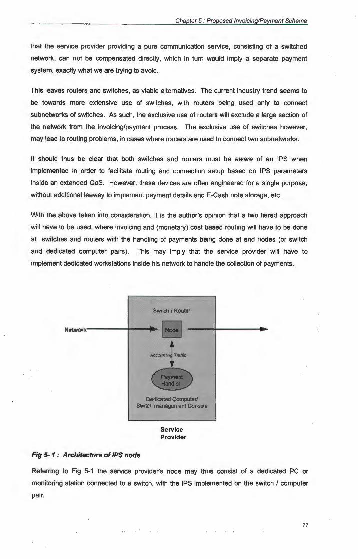
Chapter 5 : Proposed Invoicing/Payment Scheme
that the service provider providing a pure communication service, consisting of a switched
network, can not be compensated directly, which in turn would imply a separate payment
system, exactly what we are trying to avoid.
This leaves routers and switches, as viable alternatives. The current industry trend seems to
be towards more extensive use of switches, with routers being used only to connect
subnetworks of switches. As such, the exclusive use of routers will exclude a large section of
the network from the invoicing/payment process. The exclusive use of switches however,
may lead to routing problems, in cases where routers are used to connect two subnetworks.
It should thus be clear that both switches and routers must be aware of an IPS when
implemented in order to facilitate routing and connection setup based on IPS parameters
inside an extended QoS. However, these devices are often engineered for a single purpose,
without additional leeway to implement payment details and E-Cash note storage, etc.
With the above taken into consideration, it is the author's opinion that a two tiered approach
will have to be used, where invoicing and (monetary) cost based routing will have to be done
at switches and routers with the handling of payments being done at end nodes (or switch
and dedicated computer pairs). This may imply that the service provider will have to
implement dedicated workstations inside his network to handle the collection of payments.
Switch I Router
Network------t--~~ •
Dedicated Computer/ Switch management Console
Fig 5- 1 : Architecture of JPS node
Service Provider
Referring to Fig 5-1 the service provider's node may thus consist of a dedicated PC or
monitoring station connected to a switch, with the IPS implemented on the switch I computer
pair.
77
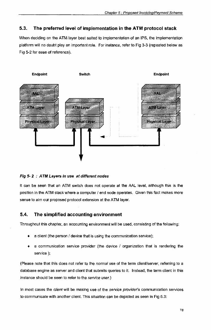
Chapter 5 : Proposed Invoicing/Payment Scheme
5.3. The preferred level of implementation in the A TM protocol stack
When deciding on the ATM layer best suited to implementation of an IPS, the implementation
platform will no doubt play an important role. For instance, refer to Fig 3-3 (repeated below as
Fig 5-2 for ease of reference).
Endpoint Switch Endpoint
Fig 5- 2 : A TM Layers in use at different nodes
It can be seen that an ATM switch does not operate at the AAL level, although this is the
position in the ATM stack where a computer I end node operates. Given this fact makes more
sense to aim our proposed protocol extension at the ATM layer.
5.4. The simplified accounting environment
Throughout this chapter, an accounting environment will be used, consisting of the following:
• a client {the person I device that is using the communication service);
• a communication service provider {the device I organization that is rendering the
service);
{Please note that this does not refer to the normal use of the term client/server, referring to a
database engine as server and client that submits queries to it. Instead, the term client in this
instance should be seen to refer to the service user.)
In most cases the client will be making use of the service provider's communication services
to communicate with another client. This situation can be depicted as seen in Fig 5.3:
78
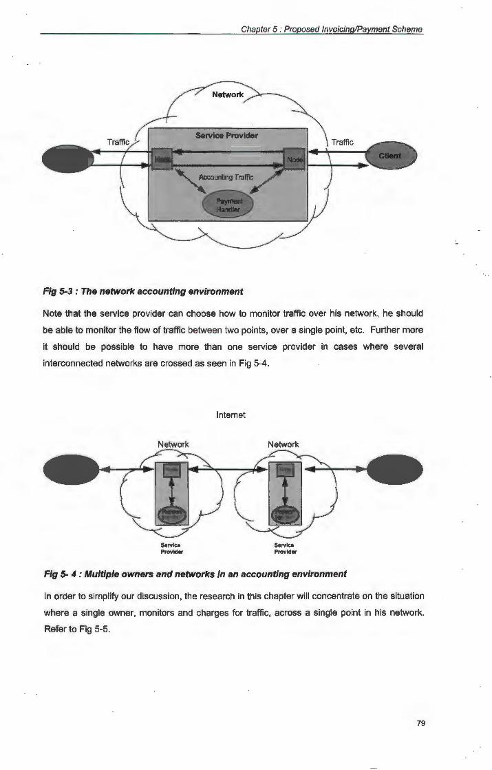
Chapter 5 : Proposed Invoicing/Payment Scheme
Seivice Provider
Fig 5-3 : The network accounting environment
Note that the service provider can choose how to monitor traffic over his network, he should
be able to monitor the flow of traffic between two points, over a single point, etc. Further more
it should be possible to have more than one service provider in cases where several
interconnected networks are crossed as seen in Fig 5-4.
Network
Service Provider
Internet
Network
Service Provider
Fig 5- 4 : Multiple owners and networks in an accounting environment
In order to simplify our discussion, the research in this chapter will concentrate on the situation
where a single owner, monitors and charges for traffic, across a single point in his network.
Refer to Fig 5-5.
79
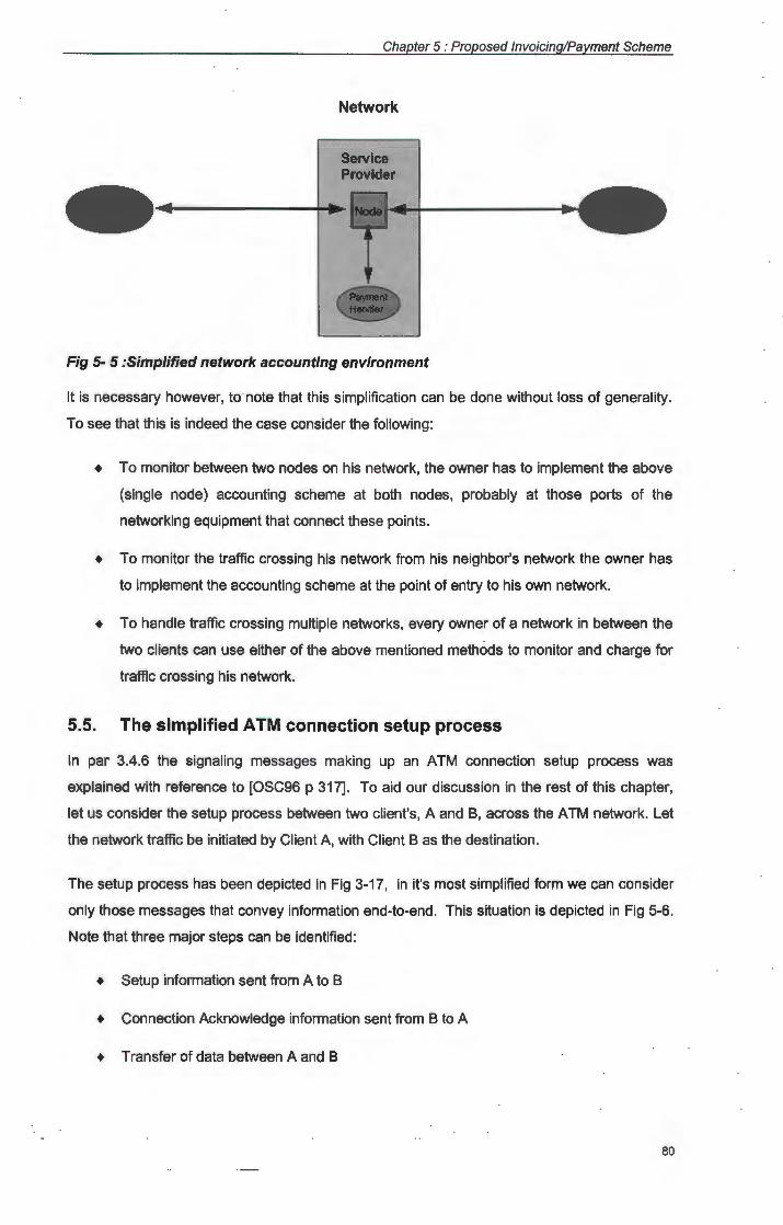
Chapter 5 : Proposed Invoicing/Payment Scheme
Network
Service Provider
-Fig 5- 5 :Simplified network accounting environment
It is necessary however, to note that this simplification can be done without loss of generality.
To see that this is indeed the case consider the following:
+ To monitor between two nodes on his network, the owner has to implement the above
(single node) accounting scheme at both nodes, probably at those ports of the
networking equipment that connect these points.
+ To monitor the traffic crossing his network from his neighbor's network the owner has
to implement the accounting scheme at the point of entry to his own network.
• To handle traffic crossing multiple networks, every owner of a network in between the
two clients can use either of the above mentioned methods to monitor and charge for
traffic crossing his network.
5.5. The simplified A TM connection setup process
In par 3.4.6 the signaling messages making up an ATM connection setup process was
explained with reference to [OSC96 p 317]. To aid our discussion in the rest of this chapter,
let us consider the setup process between two client's, A and B, across the ATM network. Let
the network traffic be initiated by Client A, with Client Bas the destination.
The setup process has been depicted in Fig 3-17, in it's most simplified form we can consider
only those messages that convey information end-to-end. This situation is depicted in Fig 5-6.
Note that three major steps can be identified:
• Setup information sent from A to B
+ Connection Acknowledge information sent from B to A
• Transfer of data between A and B
80
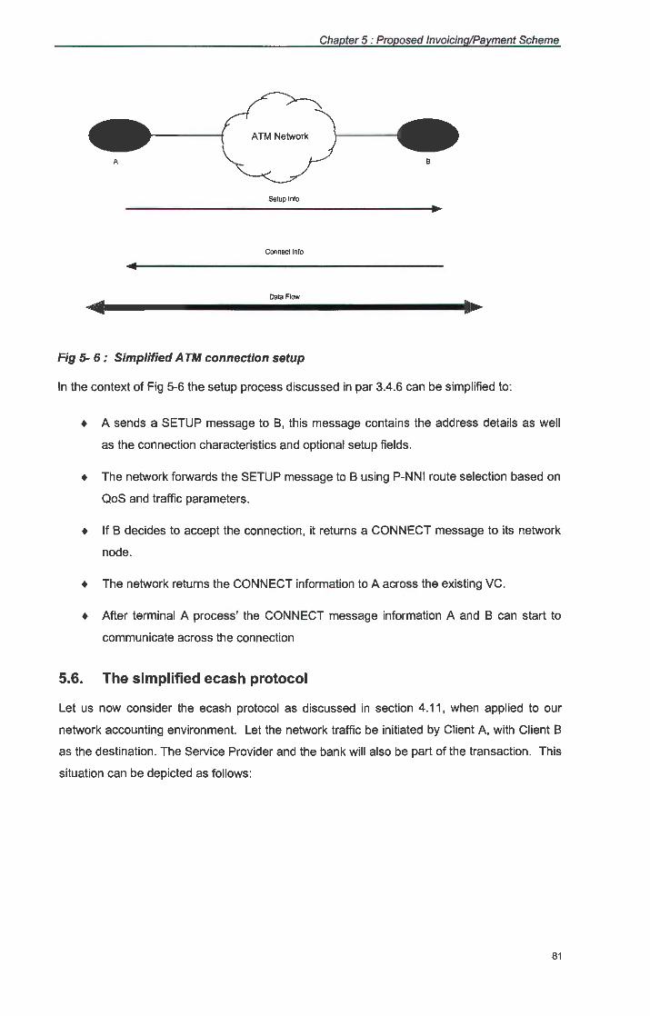
Chapter 5 : Proposed Invoicing/Payment Scheme
ATM Network
A B
Setup Info
Connect Info
Data Flow
Fig 5- 6 : Simplified A TM connection setup
In the context of Fig 5-6 the setup process discussed in par 3.4.6 can be simplified to:
+ A sends a SETUP message to B, this message contains the address details as well
as the connection characteristics and optional setup fields .
+ The network forwards the SETUP message to Busing P-NNI route selection based on
QoS and traffic parameters.
+ If B decides to accept the connection, it returns a CONNECT message to its network
node.
+ The network returns the CONNECT information to A across the existing VG.
+ After terminal A process' the CONNECT message information A and B can start to
communicate across the connection
5.6. The simplified ecash protocol
Let us now consider the ecash protocol as discussed in section 4.11, when applied to our
network accounting environment. Let the network traffic be initiated by Client A, with Client B
as the destination . The Service Provider and the bank will also be part of the transaction. This
situation can be depicted as follows :
81
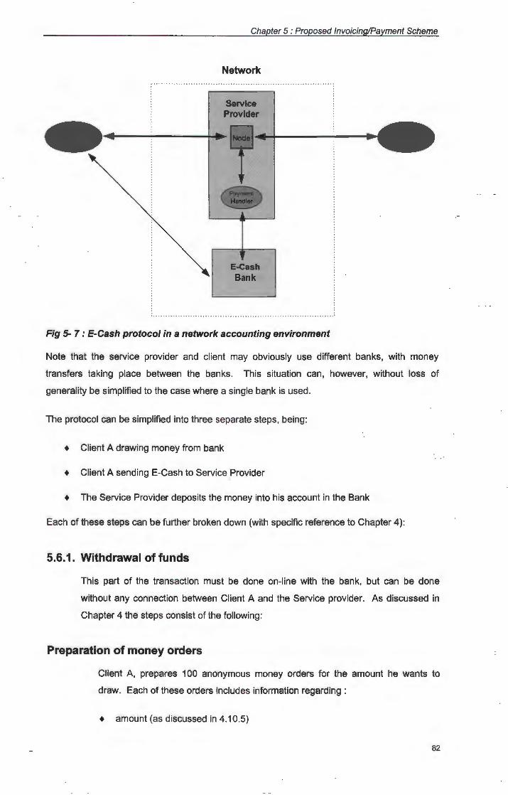
Chapter 5 : Proposed Invoicing/Payment Scheme
Network
Service Provider
-E-Cash Bank
Fig 5- 7 : E-Cash protocol in a network accounting environment
Note that the service provider and client may obviously use different banks, with money
transfers taking place between the banks. This situation can, however, without loss of
generality be simplified to the case where a single bank is used.
The protocol can be simplified into three separate steps, being:
+ Client A drawing money from bank
+ Client A sending E-Cash to Service Provider
+ The Service Provider deposits the money into his account in the Bank
Each of these steps can be further broken down (with specific reference to Chapter 4 ):
5.6.1. Withdrawal of funds
This part of the transaction must be done on-line with the bank, but can be done
without any connection between Client A and the Service provider. As discussed in
Chapter 4 the steps consist of the following:
Preparation of money orders
Client A, prepares 100 anonymous money orders for the amount he wants to
draw. Each of these orders includes information regarding :
+ amount (as discussed in 4.10.5)
82
Chapter 5 : Proposed Invoicing/Payment Scheme
+ a uniqueness string (the note number as mentioned in 4.10.1)
+ identity strings (100 split strings as discussed in par 4.10.6)
Blinding of money orders
Client A now blinds all 100 money orders (using the technique discussed in par
4.10.4) he then sends all his orders to the bank.
Verification by bank
The Bank will now asks Client A to unblind 99 of his money orders and to reveal
their identity strings. The Bank verifies the amounts and identity information (as
discussed in 4.10.7).
Signing of order
The Bank will now sign the remaining money order in it's blinded form and return it
to Client A, after deducting the corresponding amount from his account.
Unblinding of money order
Client A now unblinds his signed money order (as discussed in par 4.10.4)
This completes the withdrawal process. Client A can now save his E-Cash on a hard
disk for future use, or transmit it immediately to the Service Provider. At this stage,
Client A can break his connection with the Bank.
5.6.2. Transfer of payment
During the next phase, Client A will transfer his E-Cash to the Service Provider, this
can be done as part of the normal network traffic between the two parties. For
obvious reasons, at least Client A and the Service Provider, must have a valid
network connection at this stage. The Bank does not need to have a connection to
either of these parties during this phase.
Payment is sent to Service Provider
Client A send his E-Cash note(s), as payment, to the Service Provider where it is
accepted by the Payment Handler {this can be done either as one payment or as
a number of separate smaller payments).
83
Chapter 5 : Proposed Invoicing/Payment Scheme
Verification by service provider
The Payment Handler now checks the bank's signature to make sure the note is
valid. the Payment Handler then asks Client A to reveal either half of each of the
identity strings (using a 100 bit selector string as discussed in par 4.10.6)
This concludes the transfer phase, the E-Cash has now been successfully transmitted
from Client A to the Service Provider's Payment Handler. At this stage the connection
between the Service Provider and Client A may be broken as far as payment
transactions is concerned (it may however need to stay up as part of the service that
is rendered to Client A). The Service Provider can now save his E-Cash on a local
hard disk (i.e. the Payment Handler's disk) or he may choose to deposit his E-Cash
funds into his account at the Bank.
5.6.3. Deposit of funds
During this third and final phase, the Service Provider, deposit's his E-Cash at the
Bank, in order to complete the transaction. In this case the Service Provider and
Bank must have a valid network connection. A Connection from either of these
parties to the Client is not required at this stage.
Transfer of funds to bank
The Payment Handler sends his money to the bank.
Final Verification by bank
The bank verifies the note's signature and check it's database of spent note
numbers. If the same note number has not been deposited before it records the
note number as well s the identity information. The bank credits the Service
Provider's account with the corresponding amount. If the same note has been
spent before the bank will refuse payment and can find the perpetrator's identity
by means of the identity strings (as discussed in par 4.10.6).
This completes the E-Cash transactions, between the Client and the Service Provider. At this
stage the Service Provider may use his payment in normal monetary form, or withdraw it from
the Bank in the form of E-Cash to pay other service providers (when acting as client).
5.7. Combining ATM and ecash protocols into a simple IPS
In par 5.6 three major steps were identified in our simplified ecash protocol. With reference to
the previous two sections it should be clear that the second of these steps can be combined
84
Chapter 5 : Proposed Invoicing/Payment Scheme
with the simplified ATM connection setup process to render an IPS integrated into ATM. The
IPS protocol can then be seen to consist of the following major steps:
• A drawing money from bank
• Ecash transaction between A and Service Provider(s):
• Step 1: Setup information sent from A to B with possible routing based on
monetary cost along the way.
+ Step 2: Connection Acknowledge information sent from B to A with
quotation/invoice included.
• Step 3: Transfer of data between A and B, intermingled with ecash payments
to service provider(s} along the way.
• The Service Provider(s) deposits the money into his account in the bank
Note that as discussed in par 5.6 the initial withdrawal can be done between the bank and A
without intervention of the service provider, while the last step, the deposit, can be done
without an on-line connection between A and the service provider. As such these steps do not
need any adaptions to the ATM protocols itself, as they do not differ from that already
developed by Chaum, as discussed in chapter 4. The steps marked as Step 1 to Step 3
above do however warrant closer inspection.
5. 7 .1. Adaption to SETUP message of signaling protocol
The SETUP message of the Q.2931 signaling protocol needs to be modified in order
to include the gathering of cost information while in transit between the source and
destination UNI. It should also indicate to the NNI if routing should be done to
minimize delay (traditional routing methods like OSPF) or whether it should be done to
minimize monetary cost (regardless of delay).
In [Pry95 p 155] a number of mandatory as well as optional informational elements are
discussed (see par 3.4.1 ). The addition of four optional information elements is
proposed. These are:
+ Monetary Routing:
A single bit field, indicating that minimizing monetary cost should take precedence
over the delay cost during routing decisions when set to 1, vice versa when set to
0.
85
Chapter 5 : Proposed Invoicing/Payment Scheme
+ Total Monetary Cost:
This field is used to indicate the total cost involved per time limit or per cell. (I.e.,
a certain monetary value per 3 min interval.)
+ Time I Cell count indicator
A single bit field, indicating if the cost is computed based on time (if set to 1) or on
amount of cells (if set to 0).
+ Payment Interval:
This field is used to indicate how often during the connections lifetime a payment
should be made. It could be a measure of the amount of cells, or of the time
elapsed.
Motivation of and comments on the additional setup fields
The use of these additional fields (informational elements) are seen as one
possible solution to the problem, no doubt it will be possible to identify others as
well.
Regarding the Monetary Routing field: This field is not essential as the IPS will
function without it. It further implies certain adaptions to the P-NNI routing
schemes mentioned in 3.4.5 in order to route on other traffic characteristics than
the normal delay I hop based routing. These adaptions are seen to fall outside
the scope of this study and will not be discussed further. It should however be
noted that the inclusion of this field opens up another facet to the possible
applications of an integrated IPS. By means of this field a delay insensitive
application (i.e. an e-mail application) should be able to indicate to the network to
give it a low cost connection, thus cutting cost and providing the "most bang for
the buck" to the user.
Regarding the Total Monetary Cost field: The inclusion of this field is seen as
essential for the functioning of the IPS. The intention is that this field should
indicate to the client the total cost involved for maintaining his connection per time
I cell unit. For the purpose of this study the value of this field will refer to a
monetary value in cent.
Regarding the Payment Interval field: This field should indicate the maximum time
(or amount of cells) that may elapse between payments to the service provider(s).
For the purpose of this study the value of this field will refer to an amount of time
86
Chapter 5 : Proposed Invoicing/Payment Scheme
measured in seconds when time based, or amount of cells when cell based
payment is used.
Regarding the Time I Cell count indicator field: This field allows a user to select
either time based or cell based payment. Time based payment is not suited to
payment for low data rate/ low priority, long term connections.
Note that the Payment Interval and Total Monetary Cost fields are structured for
incremental payments. This implies that the client will be paying as he/she uses
the service provider's service and not afterwards or before. Motivation for this
choice is twofold:
• The service provider can not cheat by receiving payment and then breaking
the connection as is possible in the case of a pay before use scheme.
• The client can not cheat by using the service and breaking the connection
before payment has been sent, as is possible in the case of a use before pay
scheme.
For obvious reasons the service provider will have to consider the chosen value of
the Payment Interval field with care, so as to limit monetary loss in case of a lost
connection, while maintaining efficiency. The following should be born in mind
when deciding on a value for this field:
• Small frequent payments will have a large bandwidth overhead, while limiting
any disputes to values that are small enough to ignore.
• Large infrequent payments will have a small bandwidth overhead, but may
cause disputes to end up in court.
Computing cost and interval setup field values
Although the values of the Total monetary Cost and Payment Interval fields are
required at the UNI level they will have to be computed en route during NNI
signaling. This implies that the values at the NNI will have to be translated to the
UNI for use by the client (see [Jun96] for translation methods between UNI and
NNI).
The following methods of computation are proposed. Let every node at the NNI
level where the IPS is active identify values for the following:
• M: The monetary value payable to it's payment handler for use of it's
services.
87
Chapter 5 : Proposed Invoicing/Payment Scheme
• T: The time interval with which payments need to be made to it.
When receiving a SETUP message at the NNI, the node then performs the
following actions before transmitting the message to the next network node en
route to the destination UNI (note that this will only happen in cases where more
than one service provider is used):
• If T is smaller than the existing value in the SETUP message's Payment
Interval field: Adapt the value in the Total Monetary Cost field to the same
time I cell interval as T and replace the value in the Payment Interval field with
T.
• Add M to the value in the SETUP message's Total Monetary Cost field.
Thus, upon reaching the destination UNI the Total Monetary Cost field will hold
the total cost per time interval, payable along the complete route by the client,
while the Payment Interval field will indicate the maximum time limit allowable
between such payments.
5.7.2. Adaption to CONNECT message of signaling protocol
When routing the SETUP message through the network, the Total Monetary Cost and
Payment Interval values are computed. At the destination these values can then be
copied to the CONNECT message sent by the destination UNI to the network and
finally by the network to the source UNI. As such, it is proposed to include only two
additional fields to the CONNECT message being:
• Total Monetary Cost
• Payment Interval (per second or per cell)
As the connection route is already set when the CONNECT message is sent, the
inclusion of the Monetary Routing field in this message is not necessary.
Note that it is also possible to compute the value of these fields while the CONNECT
message is sent through the network, instead of doing the computation while sending
the SETUP message. This will keep the SETUP message smaller and may thus be
more efficient. However, the basic principle will still be the same. The advantage of
including these fields in the SETUP message is that their component values will in any
case be needed for Monetary Routing.
These fields in the CONNECT message can be seen as a quotation for cost that is
presented to the client. The moment he accepts the connect message by sending a
88
Chapter 5 : Proposed Invoicing/Payment Scheme
CONNECT ACKNOWLEDGE these fields can be seen as an invoice for payment. If
the cost is too high to the client's liking, he does not send a CONNECT
ACKNOWLEDGE, thus refusing payment and breaking the connection.
(Instead of the above method, it would also be possible to add a monetary budget to
the SETUP message, that is used up during the connect process, in a similar way as
a delay budget is handled. If the budget is reduced to zero before the destination is
reached the connection process can be stopped immediately.)
5. 7 .3. The use of STATUS signals for payment
In order to handle the transmission of payment from a client to the service provider(s)
the use of the STATUS message is proposed. Onruval [OSC96 p 315] indicates that
a STATUS message can be sent in answer to a STATUS ENQUIRY or at any other
time (mostly to indicate error conditions). He also indicates that both an end user
(client) and the network itself can be the recipient of a STATUS message.
It is proposed that the STATUS message format be adapted so that it may include an
ecash note and that payment be performed as follows:
+ The client (A in our previous example) retrieves an ecash note of value equal to
Total Monetary Cost from the bank or secondary storage, packs it in an STATUS
message and sends it to the destination (Bin our previous example).
+ An intermediate network node running IPS devaluates the ecash note in the
STATUS message with M (as discussed in par 4.10.5). It then sends the modified
note (with value = received value - M) on to the next node en route to B, while
sending the deducted ecash note (value = M) on to it's own payment handler for
storage.
Note that the intermediate nodes, which may be different service providers, should
also keep a timer indicating the amount of time elapsed between payments. If at any
stage a specific node should find T elapsed > T negotiated during setup, it will generate a
RELEASE message to both A and B, breaking the connection.
5. 7 .4. Use of IPS by end nodes
Note that the IPS is intended for use by the service provider (i.e. intermediate nodes)
the scheme is however usable without adaption for payment of end users as well.
Consider the case where client A uses information services at end node B Uust
another client from the service provider's point of view) using the service provider C's
89

Chapter 5 : Proposed Invoicing/Payment Scheme
network. A can now pay both C and B by means of the same scheme. All that is
required of B is to add it's own cost to the quotation that is generated by means of the
SETUP message, thus ensuring that A will include funds for it's own payment into the
message.
Thus far we have always assumed that the client setting up the connection will be the
one to pay the connection costs. It should however be possible to adapt the scheme
to work the other way round if necessary.
5.8. Extending the simplified IPS to a secure system
The simplified IPS scheme presented above will work inside a private domain where all
service providers can be seen as trusted. (One such example is where divisions of a mother
company use internal funds to pay cost centers inside the company for wide area network
services.) However, if used in an open environment the following problems can be identified:
+ Payment is sent in an un-encrypted format. As such, the payments can be intercepted
by any node along the way.
+ The same payment message is routed past all the IPS nodes, if a node takes more
than it's due, the client has no way to find where the problem originated.
+ Devaluation of the ecash payment along the VC, implies that the cell stream, must be
buffered while a payment message is built from consecutive cells.
In order to counter these problems certain adaptations to the SETUP message, as well as the
payment method will be necessary.
5.9. Setup for a secure IPS
Instead of the four single valued fields proposed in the simple IPS, it is proposed that a matrix
of values are sent as part of the SETUP. Each row of this data entity should refer to a specific
service provider. The fields relevant to each service provider's IPS node will then consist of:
+ Total Monetary Cost
+ Time I Cell count indicator
+ Payment Interval
+ Public Encryption Key data
+ IPS node's NSAP address
90

Chapter 5 : Proposed Invoicing/Payment Scheme
All these fields except the last two are identical to those discussed in the simple IPS. The last
two fields are used to enable the client to make an encrypted payment to a specific service
provider. As in the case of the simple IPS a single bit Monetary Routing field can be added to
the SETUP, over and above these multi valued fields.
5.10. Adding cost and interval data
In the simple IPS a node re-computes the interval and adds to the cost field when receiving a
SETUP on the NNI. In the case of the secure IPS a multiple valued SETUP message is used,
making these computations unnecessary, instead the node simply adds another informational
element (containing the above fields) to the SETUP message.
5.11. Connect for a secure IPS
In a similar way as is done for the SETUP, the CONNECT message will have to be changed in
the case of a secure IPS. Once again the data collected in the SETUP message needs to be
returned by means of the CONNECT message as a matrix instead of a number of single
valued fields.
5.12. Status (payment) messages in a secure IPS
After the initial CONNECT message is received, the client can use the NSAP addresses
returned to him to set up connections to each of the service providers that requires payment
(See Fig 5.8). The client also keeps a table of the amounts and minimum payment intervals
required by each service provider. At the specified interval the client will:
+ Retrieve an ecash note of the required amount and encrypt it using the specific
service provider's public key.
+ Send this ecash note in a STATUS message down the VC set up to the specific
service provider.
A service provider's IPS node will:
+ Decrypt any payments that are addressed to it.
+ After successful decryption, he will store the ecash note on the payment handler's
hard drive.
It is not necessary to devaluate the note as mentioned in the case of the simple IPS.
91
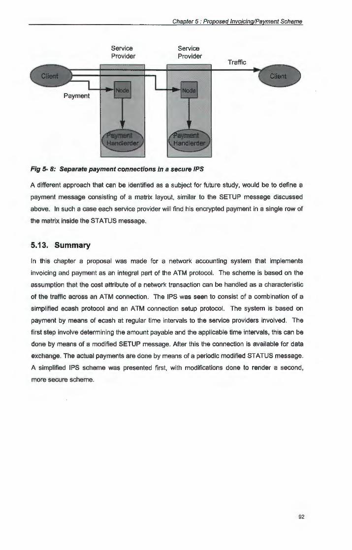
Chapter 5 : Proposed Invoicing/Payment Scheme
Service Provider
Service Provider
Fig 5- 8: Separate payment connections in a secure JPS
Traffic
A different approach that can be identified as a subject for future study, would be to define a
payment message consisting of a matrix layout, similar to the SETUP message discussed
above. In such a case each service provider will find his encrypted payment in a single row of
the matrix inside the STATUS message.
5.13. Summary
In this chapter a proposal was made for a network accounting system that implements
invoicing and payment as an integral part of the ATM protocol. The scheme is based on the
assumption that the cost attribute of a network transaction can be handled as a characteristic
of the traffic across an ATM connection . The IPS was seen to consist of a combination of a
simplified ecash protocol and an ATM connection setup protocol. The system is based on
payment by means of ecash at regular time intervals to the service providers involved. The
first step involve determining the amount payable and the applicable time intervals, this can be
done by means of a modified SETUP message. After this the connection is available for data
exchange. The actual payments are done by means of a periodic modified STATUS message.
A simplified IPS scheme was presented first, with modifications done to render a second,
more secure scheme.
92
Chapter 6
Evaluation
6.1. Introduction
The previous chapter concentrated on the proposal of an accounting scheme that is
embedded into the ATM protocol itself, without necessarily indicating how feasible such a
scheme may be in real life. In this chapter we will take a closer look at the overhead as well
as the advantages and disadvantages of this scheme in order to evaluate the proposed
scheme. Due to the fact that an implementation of this scheme will imply a change in all ATM
equipment used in the trial, it is not practical to implement a test network. The programming of
a simulation, although practical, is not seen to fall inside the scope of this study. It will
however, be possible to investigate the viability of this scheme by means of an analytical
approach.
6.2. Changes to the ATM signaling and routing protocols
In the previous chapter the following changes to ATM were proposed:
Changes to the routing algorithm to allow routing on monetary cost
Additions to the Q.2931 signal informational elements
The first of these changes were shown to be optional, although it's inclusion will open a
number of new possible avenues to IPS application. As routing methods were not seen as
part of the scope of this study, this option will not form part of our evaluation.
The second change does however influence the viability of our proposed IPS as it can not be
seen to be optional.
By simply adding informational elements to the Q.2931 SETUP signal, the impact of the IPS
on the ATM architecture is kept to a minimum. It does however imply that a certain penalty
will be paid regarding the number of bits needed to complete the setup.
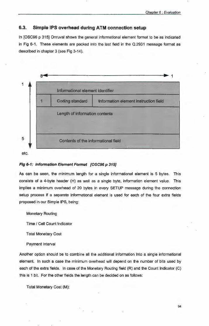
Chapter 6 : Evaluation
6.3. Simple IPS overhead during ATM connection setup
In [OSC96 p 315] Onruval shows the general informational element format to be as indicated
in Fig 6-1. These elements are packed into the last field in the Q.2931 message format as
described in chapter 3 (see Fig 3-14).
1
1
Informational element identifier
1 Coding standard Information element instruction field
Length of information contents
5 Contents of the informational field
etc.
Fig 6-1: Information Element Format [OSC96 p 315]
As can be seen, the minimum length for a single informational element is 5 bytes. This
consists of a 4-byte header (H) as well as a single byte, information element value. This
implies a minimum overhead of 20 bytes in every SETUP message during the connection
setup process if a separate informational element is used for each of the four extra fields
proposed in our Simple IPS, being:
Monetary Routing
Time I Cell Count Indicator
Total Monetary Cost
Payment Interval
Another option should be to combine all the additional information into a single informational
element. In such a case the minimum overhead will depend on the number of bits used by
each of the extra fields. In case of the Monetary Routing field (R) and the Count Indicator (C)
this is 1 bit. For the other fields the length can be decided on as follows:
Total Monetary Cost (M):
94
Chapter 6 : Evaluation
This field has been defined to indicate a certain coin value indicated in cent. For
reasons discussed in chapter five, the payment interval is expected to be quite small.
As such the total monetary cost is not expected to be extremely high, a value of 216 is
expected to be sufficient. This implies a minimum of 2 bytes to be reserved for this
field, rendering a total amount of 65535c (R/$ 655.35) per payment.
Take note that this field indicates a quotation, and as such can use an open format,
and will thus not carry the encryption and other overheads that ecash has to carry.
Payment Interval (T):
Once again the relative small expected time intervals between payments will influence
the length of this field. To use only one byte for this field will imply a restriction of 4
min between payments. This may be sufficient for most transactions, but it was the
author's opinion that at least a 10-min interval should be possible. It is therefore
proposed to use 2 bytes in this case as well, giving a maximum value of 18 hours
between payments.
If a combined approach is therefore taken, the total difference in the number of bits (L) would
then be:
Delta Lsetup =
= (8x4)+(1)+(1)+(8x2)+ (8x2)
= 66 bits
If two bits in one of the T bytes are used to store R and C, the above 66 bits can be shrunk to
a minimum of 8 bytes overhead in each SETUP message sent.
Depending on the method chosen, Lsetup can therefore be seen to incur an additional cost of
between 8 and 20 bytes. (Note that the implementation giving Delta Lsetup = 20 bytes may still
be better due to simplicity during application development. This will also give more
adaptability during future extensions.)
Referring back to Fig 3-14 and Fig 6-1, the minimum length for a Q.2931 message can be
seen to be:
L = LQ.2931 Header + Lin! Element
= (8 x 9) + (8 x 5)
= 112 bits
95

Chapter 6 : Evaluation
However [Pry95 p 155] lists at least four compulsory informational elements for a SETUP
message. (See par 3.4.1 for detail.) That implies that Lsetup should be at least:
Lsetup = LQ.2931 Header + (4 X LlnfElement)
= (8 x 9) + 4 x (8 x 5)
= 232 bits
Giving our new minimum length for a SETUP message L'setup with IPS active as:
L'setup = Lsetup + Delta Lsetup
= 232 + 66
= 298
This implies a percentage increase of:
IPS Overhead setup = 100 X (L'setup - Lsetup) f Lsetup
= 28.44 %
For obvious reasons the increase in length of the CONNECT message will increase with the
same amount (only the one bit Monetary Routing Field falls away). As mentioned in chapter 5
it is possible to change the proposed scheme to make the Total Monetary Cost and Payment
Interval fields fall away in the SETUP message. If this route is followed during implementation
it would imply a Delta Lsetup = 40 bits and a Delta Lconnect = 66.
It should however be pointed out that this overhead is only paid during setup, which occurs
only once in a connections lifetime. Thus, at ATM bit speeds the setup overhead should be a
negligible percentage of total traffic.
6.4. Overhead of Secure IPS during ATM connection setup
As discussed in the previous chapter, the Simple IPS can be adapted, by trading overhead for
security, in order to render a Secure IPS. This version of the IPS uses a matrix layout inside
the SETUP message with one line for each service provider in the path.
As discussed in chapter 5 this version uses two additional fields, being:
96
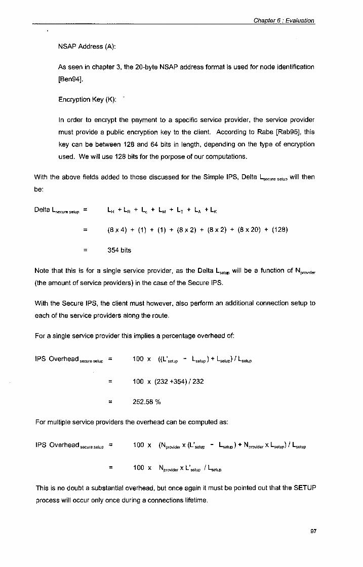
Chapter 6 : Evaluation
NSAP Address (A):
As seen in chapter 3, the 20-byte NSAP address format is used for node identification
[Ben94].
Encryption Key (K): •
In order to encrypt the payment to a specific service provider, the service provider
must provide a public encryption key to the client. According to Rabe [Rab95], this
key can be between 128 and 64 bits in length, depending on the type of encryption
used. We will use 128 bits for the porpose of our computations.
With the above fields added to those discussed for the Simple IPS, Delta Lsecure setup will then
be:
Delta Lsecure setup =
= (8x4) + (1) + (1) + (8x2) + (8x2) + (8x20) + (128)
= 354 bits
Note that this is for a single service provider, as the Delta Lsetup will be a function of Nprovider
(the amount of service providers) in the case of the Secure IPS.
With the Secure IPS, the client must however, also perform an additional connection setup to
each of the service providers along the route.
For a single service provider this implies a percentage overhead of:
IPS Overhead secure setup = 100 X ((L' setup - Lsetup } + Lsetup} f Lsetup
= 100 x (232 +354) I 232
= 252.58 %
For multiple service providers the overhead can be computed as:
I PS Overhead secure setup = 100 X (Nprovider X (L' setup - Lsetup} + Nprovider X Lsetup} f Lsetup
= 1 00 X Nprovider X L' setup f Lsetup
This is no doubt a substantial overhead, but once again it must be pointed out that the SETUP
process will occur only once during a connections lifetime.
97
Chapter 6 : Evaluation
6.5. Overhead during data transfer of Simple IPS
The overhead during payment by ecash can, be considerable and will be incurred more than
once during a connections lifetime. Due to the nature of our proposed IPS, the precise value
will vary according to the Payment Interval (T) chosen by the service provider(s).
In chapter 5 it was proposed to handle payment by inserting ecash into the STATUS message
available as part of the Q.2931 signaling protocol. As in the previous section it will be
necessary to examine how many additional bits are necessary to implement IPS.
The same message format as that described by Fig 3-14 and Fig 6-1 will be used to send the
STATUS message. However, unlike the case of the SETUP message, the whole message
will have to be interpreted as overhead in this case.
It should be clear that the exact length of the STATUS/Payment message will depend heavily
on the length used for ecash representation. This in turn will depend on the specific ecash
implementation scheme being used. However, we can make certain assumptions regarding
the minimum length of a generic ecash implementation. From the discussion in Chapter 4 we
can assume that at least the following information will have to be represented in the ecash
note:
Note number (uniqueness string)
Signature
Monetary value
Identity strings
As discussed in par 4.10.5 it is possible to include the monetary value in the signature itself.
In par 4.10.3 it was also mentioned that the signature can be applied by using RSA encryption
on the note number itself. Using these techniques will allow us to implement ecash using a
representation that will pack all of the above mentioned logical fields into a record containing
only a note number and Identity string fields.
When examining these two fields we can make assumptions on their minimum length based
on the following:
Note number:
In par 4.10.3 it was pointed out that 150 digits can be considered as the minimum
length for a note number when using RSA encryption on it [DigNum]. If using a
normal ASCII representation of these digits or possibly a packed decimal
representation, we can thus assume a 150-byte string.
98
Chapter 6 : Evaluation
Identity Strings:
In [Sch94] Shneier proposes the use of 100 identity strings, each consisting of a left
and a right half, that will reveal the user's identity in case of double spending. If the
normal Pascal type string is used this implies 100 x 256 bytes. It should however be
possible to develop an implementation using a smaller string value, or to use fewer
strings in order to limit the number of bits required. Another option is to do away with
the anonymous property of ecash and replace these strings by a single identity string
in non-encrypted form. We will however, use the 100 x 256 bytes, worse case, for our
computations in this section.
This brings the minimum length for a payment message to:
= LMessage Header + Linformation Element Header + LNote Number + Lldentity
= (8 x 9) + (8 x 4) + (8 x 150) + (8 x 100 x 256)
= 206, 104 bits
Depending on the value of T, this value can be said to be big enough to make a difference in
the throughput of the ATM connection. When carefully chosen however, the overhead can be
surprisingly small. As an example consider a 100 Mb/s connection with a value of T = 60 sec
(1 min).
This will imply that the total amount of bits sent per minute is :
Total Bits sent = 100 x 1024 x 1024 x 60
= 6,291,456,000
However, with Lpay at a minimum equal to 206,104 bits (as discussed above) the amount of
bits available to transport normal ATM cells is:
Normal A TM bits = Total Bits sent - Lpay
= 6,291,456,000 - 206, 104
= 6,291,249,896
99
Chapter 6 : Evaluation
Expressed as a total percentage of the throughput, this represents an overhead of :
IPS Overheadpay = 100 x (6,291,456,000 - 6,291,249,896) I 6,291,456,000
= 0.00328 %
(Note that the above disregards the overhead of the ATM header itself, which will be added to
both the normal and the payment parts of the traffic flow during SAR.) In a similar manner the
percentage overhead for other values of T can be estimated.
6.6. Overhead during data transfer of Secure IPS
The Secure IPS uses a separate payment message to each of the service providers along the
way. As such the overhead during data transfer will once again be a function of Nprovider (the
amount of service providers).
It should be clear that the case of a single service provider is equivalent to the overhead of the
Simple IPS as discussed above, as both require a single payment message with the exact
same fields. The situation will however differ considerably in the case of multiple service
providers where Lpay needs to be multiplied by Nprovider . This implies that the Normal ATM bits
will be:
Normal ATM bits = Total Bits sent - ( Lpay x Nprovider)
bringing the percentage overhead to :
IPS Overheadpay = 100 x ( Lpay x Nprovider ) I Total Bits sent
= 20,610,400 x Nprovider I Total Bits sent
6.7. Conclusion regarding feasibility
From the above it can be seen that a simple IPS will carry a 28% overhead during connection
setup and a 0.003% or lower overhead during data transfer (due to periodic payment) for
transfer rates of 100 Mb/s and higher and payment intervals of 1 min and above. (Less than
0.0005 % at T=10 min)
Thus it can be inferred on bit overhead considerations, that the Simple IPS is viable. The
viability of the Secure IPS will depend on the number of service providers involved. It will
however be wise to also consider added latency per node due to the additional computational
overhead. However, this value will be heavily dependent on the computational ability and
speed of nodes themselves and is thus not considered to lend itself to analytical evaluation.
100
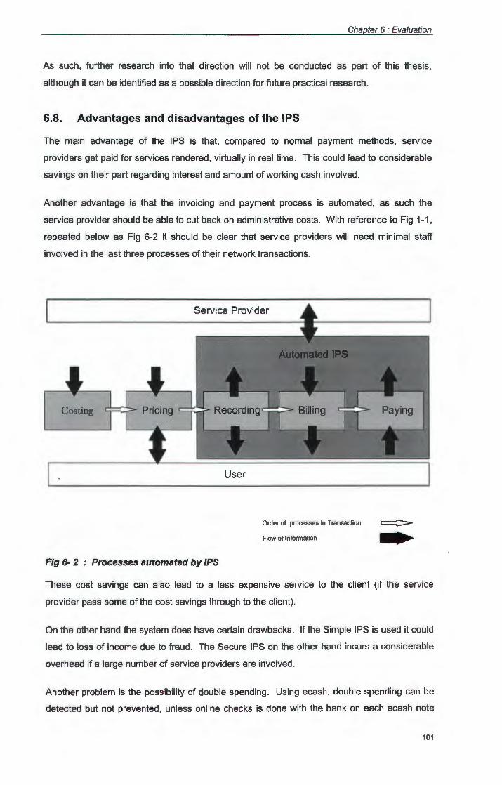
Chapter 6 : Evaluation
As such, further research into that direction will not be conducted as part of this thesis,
although it can be identified as a possible direction for future practical research.
6.8. Advantages and disadvantages of the IPS
The main advantage of the IPS is that, compared to normal payment methods, service
providers get paid for services rendered , virtually in real time. This could lead to considerable
savings on their part regarding interest and amount of working cash involved.
Another advantage is that the invoicing and payment process is automated, as such the
service provider should be able to cut back on administrative costs . With reference to Fig 1-1,
repeated below as Fig 6-2 it should be clear that service providers will need minimal staff
involved in the last three processes of their network transactions.
Service Provider
Costing
Order of processes in Transaction
Flow of Information
Fig 6- 2 : Processes automated by JPS
These cost savings can also lead to a less expensive service to the client (if the service
provider pass some of the cost savings through to the client).
On the other hand the system does have certain drawbacks. If the Simple IPS is used it could
lead to loss of income due to fraud . The Secure IPS on the other hand incurs a considerable
overhead if a large number of service providers are involved.
Another problem is the possibility of double spending. Using ecash, double spending can be
detected but not prevented, unless online checks is done with the bank on each ecash note
101
Chapter 6 : Evaluation
before it is accepted. This implies a credit check per ecash note, which may lead the service
provider to consider a different payment method. One possibility is the use of credit card
numbers, where the credit check can be done per user, instead of per note, using the existing
credit card infrastructures.
6.9. Summary
In this chapter the feasibility of the network accounting scheme, proposed in chapter five was
investigated. By means of computations it was shown that the scheme can be considered
viable for higher data transfer speeds when payment is not required at an interval shorter than
1 minute. (Overhead was shown to be close to 0.003% for 100 Mb/s transfer rate with a 1-min
payment interval using a single service provider.) These computations were based on bit
overhead alone and did not consider computational latency. When considering the
advantages and disadvantages of the scheme, it was however pointed out that problems like
the possibility of double spending, may make different electronic payment methods preferable.
102
Chapter 7
Conclusion
This thesis started off, by indicating the need for a more creative approach towards the
payment of high speed networking services. A number of objectives were set in chapter one,
with a hypothesis indicating that the use of ecash payment may be the solution to our payment
problem.
In chapter two it was indicated that the mature, but low speed, protocols in use today, will no
longer be sufficient to render a usable network service in the future. Thus, newer, high speed
networking technologies should be considered in order to cope with the ever-increasing
demand in bandwidth. It was also pointed out that this technology will include high speed
protocols like ATM as well as high speed networking devices like switches. These protocols
and devices were briefly discussed in order to aid the discussion in following chapters.
Chapter three took a closer look at ATM, as well as the definition thereof. The discussion
included the different layers of the ATM implementation and indicated the various sub
protocols operating at each layer. Closer attention was also paid to the functions of each of
these layers. The chapter concluded with a section indicating the signaling, addressing and
routing necessary for ATM connection setup, as well as a summary of the messages sent
during setup.
Chapter four introduced the concept of electronic cash, as money that is represented by
numbers. The characteristics of ecash were discussed and compared with that of normal
cash. An overview of a general ecash transaction was given after which the techniques used
in the ecash protocols were discussed. Finally an ecash protocol was presented, and an
example given to indicate how a transaction between a payer, a service provider and the bank
should take place.
In chapter five a proposal was made for a network accounting system that implements
invoicing and payment as an integral part of the A TM protocol. The scheme is based on the
assumption that the cost attribute of a network transaction can be handled as a characteristic
of the traffic across an ATM connection. The IPS was seen to consist of a combination of a
simplified ecash protocol and an ATM connection setup protocol. The system is based on
payment by means of ecash at regular time intervals to the service providers involved. The
Chapter 7 : Conclusion
first step involve determining the amount payable and the applicable time intervals, this can be
done by means of a modified SETUP message. After this the connection is available for data
exchange. The actual payments are done by means of a periodic modified STATUS message.
Two methods were discussed, one IPS optimized for minimum overhead and the other for
security.
In chapter six the workability of the network accounting scheme was investigated. Due to the
fact that an implementation of the proposed IPS would imply a number of adaptions to the
hardware and software at each service provider node, an implementation was not attempted
as part of this research. Instead an analytical approach was taken. By means of
computations it was shown that the scheme can be considered viable for higher data transfer
speeds when payment is not required at an interval shorter than 1 minute. (Overhead was
shown to be close to 0.003% for 100 Mb/s transfer rate with a 1-min payment interval.) These
computations were based on bit overhead alone and did not consider computational latency.
A major problem pointed out, was that ecash only allows the detection of double spending and
not the prevention thereof (in cases where the bank is off-line). This implied that a service
provider has to do a credit check per ecash note if he wants to be sure that a payment made
to him is valid.
7 .1. Feasibility of Proposed Extension to ATM
Based on the discussion in chapter six it was seen that a network accounting scheme
implemented as an integral part of the ATM protocol is feasible, when basing a decision purely
on bit overhead considerations. However, due to the nature of ecash, the possibility of double
spending could cause a serious problem. As such, the anonymous nature of ecash can be
seen as the only gain over payment methods such as the use of credit card numbers. A
theme that can be considered for future study, is the use of credit card based payments,
instead of ecash, in combination with the rest of the proposed IPS.
7 .2. Objectives Reached
In chapter one it was mentioned that the objectives of this research includes:
To understand ATM;
To understand electronic billing and ecash;
To propose an ATM-embedded billing and payment method;
To evaluate this method by means of computations.
This thesis started off with a discussion regarding the general high speed networking
environment of today and the future. After that ATM was discussed in more depth in chapter
104
Chapter 7 : Conclusion
three, providing understanding of ATM in general and thus reaching the first objective of this
research.
Further objectives were reached in chapter four during the discussion on electronic cash.
Finally chapters five and six covered the last two objectives by proposing and evaluating an
A TM embedded network accounting scheme.
It can therefore be stated that all the objectives stated in chapter one was reached. The next
section will summarize the main issues covered in the chapter two to six of this thesis.
7 .3. Conclusion
Given the above facts it can be seen that it is indeed possible to implement an accounting
system by using a form of electronic cash and incorporating recording, billing and payment as
an integral part of the high speed networking protocol, as was stated in the hypotheses in
chapter one. However, in cases where privacy and the anonymous nature of ecash is not a
priority, existing methods, like the use of credit cards, may present a lower overhead cost.
105
Chapter 7 : Conclusion
Appendices
Appendix A: Notes on Smart cards vs Ecash
One drawback of ecash, is that it is not possible to spend your money without the help of
some form of electronic device to handle the transaction and on which to keep your digital
purse. Although the modern day PC have become quite portable it is however not ideal to
take a notebook with when shopping. In order to extend the use of ecash to off-line payments,
the development of smart cards should be seen as a parallel development to that of ecash and
not only as part of the development cycle of ecash itself.
In a recent address to the US House of Representatives [Cha95], dr Chaum made it clear that
he sees the use of smart cards as more applicable to off-line, and that of ecash as more
applicable to on-line payments. However, he also predicted that the trend would be to the
convergence of these two methods into a hybrid, since people do not want incompatible forms
of money and it offers the best of both worlds in terms of convenience. As the scope of this
research concerns the use of ecash to pay for on-line network transactions, smart cards will
not be discussed in detail.
106
Chapter 7 : Conclusion
Bibliography
[Axn93] David H. Axner. Evaluating switching hub architectures. Business Communications Review, July 1993.
[Ben94] David Benham. ATM in local area networks, a tutorial. Hughes LAN Systems, Calafornia, USA, 1994.
[BW94] Charles N Brownstein Terry Weigler. Electronic cash, Tokens and Payments in the National Information Infrastructure. Cross-Industry Working Team Corporation for National Research.FTP:[email protected]
[Cha85] David Chaum. Security without identification: Transaction systems to make big brother obsolete. Communications of the ACM, 28(10): 1030-1040 October 1995.
[Cha92] David Chaum. Achieving Electronic Privacy. Scientific American, August 1992, pages 96-101.
[Cha95] David Chaum. David Chaum's testimony for the US House of Representatives, Committee on Banking and Financial Services. http//www.digicash.com/publish July 1995.
[CPF92] Srinivasan Keshav Colin Paris and Dominico Ferrari. A framework for the study of pricing in integrated networks. Technical report, University of California, Berkely, Internet FTP: icsi-ftp.Berkely.EDU, 1992.
[Dav94] Dai Davies. There is no such thing as a free Internet. In Proc. INET94/JENC5. INTERNET, 1994.
[FGV94] Domenico Ferrari, Amit Gupta, Giorgio Ventre. Distributed advance reservation of real-time connections. The Tenet Group, University of California at Berkeley and the International Computer Science Institute, Berkely, California.November 1994.
[GF94] Amit Gupta and Dominico Ferrari. Resource partitioning for multi-party real-time communication. Thechnical Report TR-94-061, University of California at Berkeley and the International Computer Science Institute, Berkely, California, 1994.
[HMS94] R Handel, M Huber and S Schroder. ATM Networks concepts, protocols, applications. Addison Wesley, Cambridge, 1994.
[Kur93] J F Kurose. Open issues and challenges in proving quality of service guarantees in high speed networks. ACM Communication Review, Vol 23, no 1, pages 6 -15, January 1993.
[Jai94] Raj Jain. High Speed Networking using Fiber and other Media. Addison Wesley, 1994.
108
Chapter 7 : Conclusion
[Jun96] Jae-IL Jung. Translation of QoS requirements into ATM performance parameters in B-ISDN. Computer Networks and ISDN Systems 28 (1996) p 1753 - 1767.
[LV94] S Low and P Varaiya. An algorithm for the optimal service provisioning using resource pricing. Proceedings of the Conference on Computer Communications {IEEE lnfocom), Toronto, Canada June 1994.
[Lin93] Yancy Lind. lnteligent switching hubs: The answer to the LAN bandwidth shortage? Telecomunications (Americas Edition), October 1993
[MN94] Amit Gupta Wingwai Howe Mark Moran and Quyen Nguyen® Scalable resource reservation for multi-party real-time communication. Thechnical Report TR-94-050, University of California at Berkeley and the International Computer Science Institute, Berkely, California, 1994.
[NT94] Novell Networking Technologies study guide. Novell 1994.
[Nov94] Novell 3.12 Online Documentation CD. Novell 1994.
[OSC96] Raif Onruval, Hal Sandick, Rao Cherukuri. Structure and use of signaling in BISDNs. Computer and ISDN Systems 28 (1996) p 307-323.
[Par94] Craig Partridge. Gigabit Networking. Addison Wesley, 1994.
[PF92] Colin Parris and Dominico Ferrari. A resource based pricing policy for real-time channels in a packet switching network. Technical report, University of California, Berkeley, Internet FTP: icsi-ftp.Berkeley.EDU, 1992.
[PRY95] Marten de Pryker. Asynchronous Transfer Mode, solution for broadband ISDN. Third Edition. Prentice Hall, Antwerp Belgium, 1994.
[Rab95] Cobus Rabe. Data security course. Faculty of Military Science, University of Stellenbosch. Military Academy, Saldanha, 1995.
[Ser94] Christopher Serjak. Switching Paradigms, everything has changed except the network. Bay Networks, Northeast Consulting Resources, Boston, USA, 1994.
[Sch94] Bruce Schneier. Applied Cryptography. John Wiley and Sons, 1994.
[Smu95] Walter B Smuts. Paying for High speed Network Services. Dept of Computer Science and Information Systems, Unisa November 1995.
[TCP94] Novell Netware TCP/IP services study guide. Novell 1994.
[Zha91] R Cocchi D Estrin S Shenker L Zhang. A study of priority pricing in multiple service class networks. In proceedings of the ACM SIGCOM 19991 Conference, pages 123-130. ACM, 1991.
109
Chapter 7 : Conclusion
Internet Sources
[ATMFrm] ATM Forum home page. ATM White Papers http://www.ATMForum.com
[CybPmn] CyberCash home page. The secure Internet Payment System http://www.cybercash.com
[DigChk] Digicash publications. Online Cash Checks http//www.digicash.com/publish/online.html
[DigCrd] Digicash publications. Prepaid Smart Card Techniques http//www.digicash.com/publish/cardcom.html
[Diglnt] Digicash tutorials. An introduction to ecash. http//www.digicash.com/publish/ecash_intro/ecash_intro.html
[DigMon] Digicash home page. Money on the Internet http//www.digicash.com/ecash/moneyonnet.html
[DigNum] Digicash publications. Numbers that are money http//www.digicash.com/publish/digibro.html
[DigSig] Digicash Tutorials. Digital signatures and smart cards http//www.digicash.com/publish/digsig/digbig.html
[EunCsh] EUnet home page. Europeans can make cash Purchases on the Information Superhighway http://www.eu.net/press/pres960313ecash .html
[MtbAnn] Ecash Announcement http://www.marktwain.com/announce.html
[MtbFaq] Ecash Mark Twain Bank Frequently asked questions http://www.marktwain.com/digifaq .html
[MtbFee] Ecash Fee Schedule http://www. marktwain .com/fee.html
[MtbMon] How does Money move http://www.marktwain.com/money.html
[MtbWir] Mark Twain Bank : Wire transfer instructions http://www.marktwain.com/wire.html
[MtbWis] What is Ecash http://www.marktwain.com/whatis.html
110