pau-sara: a l1-gps band radiometer and...
TRANSCRIPT

© R.S. Lab, UPC 2010. GNSS-R10, Barcelona, 21st-22nd October 2010
PAU-SARA: a L1-GPS Band Radiometer and Reflectometer with Digital Beamforming and
Polarization Synthesis
X. Bosch-Lluis, N. Rodríguez-Álvarez, A. Camps,
E. Valencia, I. Ramos-Perez, H. Park.
Remote Sensing Lab, Dept. Teoria del Senyal i Comunicacions,
Universitat Politècnica de Catalunya
and IEEC-CRAE/UPC
Tel. +34 93 405 46 64, E-08034 Barcelona, Spain.
E-mail: [email protected]

2/18© R.S. Lab, UPC 2010. GNSS-R10, Barcelona, 21st-22nd October 2010
PAU-SARA: a L1-GPS Band Radiometer and Reflectometerwith Digital Beamforming and Polarization Synthesis
1. Introduction
2. PAU-SARA
3. SMIGOL Reflectometer
4. Conducted Field Experiment1. Pointing to the Horizon (IP-Reflectometer)2. Pointing to θi=45º (Radiometer)
5. Conclusions
0. Outline
3/18© R.S. Lab, UPC 2010. GNSS-R10, Barcelona, 21st-22nd October 2010
PAU-SARA: a L1-GPS Band Radiometer and Reflectometerwith Digital Beamforming and Polarization Synthesis
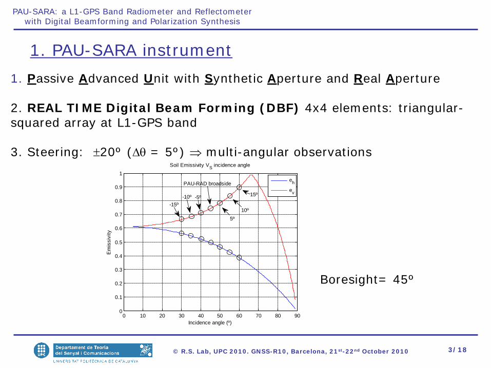
1. PAU-SARA instrument
1. Passive Advanced Unit with Synthetic Aperture and Real Aperture
2. REAL TIME Digital Beam Forming (DBF) 4x4 elements: triangular-squared array at L1-GPS band
3. Steering: ±20º (∆θ = 5º) ⇒ multi-angular observations
0 10 20 30 40 50 60 70 80 900
0.1
0.2
0.3
0.4
0.5
0.6
0.7
0.8
0.9
1
Incidence angle (º)
Em
issi
vity
Soil Emissivity VS incidence angle
eh
ev
-15º-5º-10º
5º10º
15º
PAU-RAD broadside
Boresight= 45º
4/18© R.S. Lab, UPC 2010. GNSS-R10, Barcelona, 21st-22nd October 2010
PAU-SARA: a L1-GPS Band Radiometer and Reflectometerwith Digital Beamforming and Polarization Synthesis
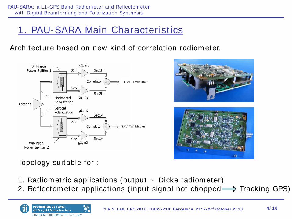
1. PAU-SARA Main Characteristics
Architecture based on new kind of correlation radiometer.
TAH –Twilkinson
TAV-TWilkinson
Topology suitable for :
1. Radiometric applications (output ~ Dicke radiometer)2. Reflectometer applications (input signal not chopped Tracking GPS)

5/18© R.S. Lab, UPC 2010. GNSS-R10, Barcelona, 21st-22nd October 2010
PAU-SARA: a L1-GPS Band Radiometer and Reflectometerwith Digital Beamforming and Polarization Synthesis
2.PAU-SARA PerformanceSynthesized beams as Real Aperture Radiometer measured at the UPC anechoic chamber.
-80 -60 -40 -20 0 20 40 60 80-30
-25
-20
-15
-10
-5
0
Scanned angle θ (º)
Nor
mal
ized
arra
y fa
ctor
|Sa|2-|Sw|2 for H-pol
0º5º-5º10º-10º15º-15º20º-20º
6/18© R.S. Lab, UPC 2010. GNSS-R10, Barcelona, 21st-22nd October 2010
PAU-SARA: a L1-GPS Band Radiometer and Reflectometerwith Digital Beamforming and Polarization Synthesis
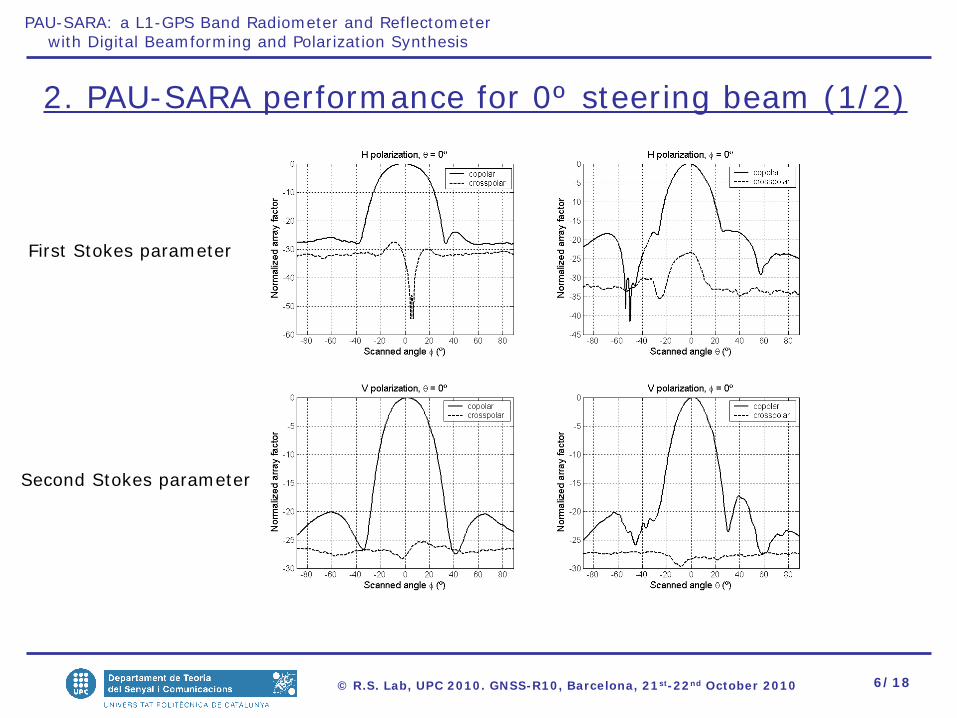
2. PAU-SARA performance for 0º steering beam (1/2)
First Stokes parameter
Second Stokes parameter
7/18© R.S. Lab, UPC 2010. GNSS-R10, Barcelona, 21st-22nd October 2010
PAU-SARA: a L1-GPS Band Radiometer and Reflectometerwith Digital Beamforming and Polarization Synthesis
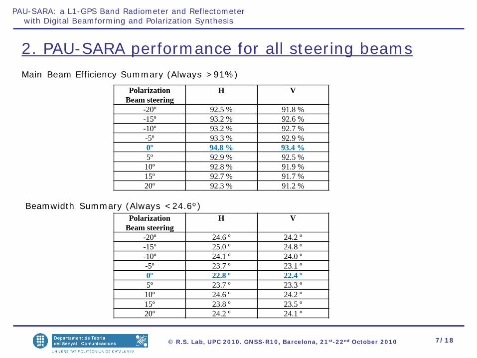
2. PAU-SARA performance for all steering beams
PolarizationBeam steering
H V
-20º 92.5 % 91.8 %-15º 93.2 % 92.6 %-10º 93.2 % 92.7 %-5º 93.3 % 92.9 %0º 94.8 % 93.4 %5º 92.9 % 92.5 %10º 92.8 % 91.9 %15º 92.7 % 91.7 %20º 92.3 % 91.2 %
PolarizationBeam steering
H V
-20º 24.6 º 24.2 º-15º 25.0 º 24.8 º-10º 24.1 º 24.0 º-5º 23.7 º 23.1 º0º 22.8 º 22.4 º5º 23.7 º 23.3 º10º 24.6 º 24.2 º15º 23.8 º 23.5 º20º 24.2 º 24.1 º
Main Beam Efficiency Summary (Always >91%)
Beamwidth Summary (Always <24.6º)

8/18© R.S. Lab, UPC 2010. GNSS-R10, Barcelona, 21st-22nd October 2010
PAU-SARA: a L1-GPS Band Radiometer and Reflectometerwith Digital Beamforming and Polarization Synthesis
3. SMIGOL Reflectometer
1. Working frequency = 1.57542 GHz (GPS L1)2. Measures the interference between direct and reflected signals during all the satellite passages.3. The IPT and the SMIGOL-Reflectometer can also be used to retrieve topography, soil moisture over vegetation-covered soils, and vegetation height as it has been tested in [1]
The Soil Moisture Interference-pattern GNSS Observations at L-band (SMIGOL) Reflectometer is theinstrument implementing the IPT.
[1] Rodriguez-Alvarez, N., Camps, A., Vall-Llossera, M., Bosch-Lluis, X., Monerrris, A., Ramos-Perez, I., Valencia, E., Marchan-Hernandez, J.F., Martinez-Fernandez,J., Baroncini-Turricchia, G., Pérez-Gutiérrez C., Sánchez, N., “Land Geophysical Parameters Retrieval Using The Interference Pattern GNSS-R Technique” IEEE Transactions on Geoscience and Remote Sensing, DOI: 10.1109/TGRS.2010.2049023
You can find more information about SMIGOL-Reflectometer and the IPT in the poster session, where a summaryof their applications is shown.
LAND RETRIEVALS: THE SMIGOL-REFLECTOMETER AND THE INTERFERENCE PATTERN TECHNIQUE

9/18© R.S. Lab, UPC 2010. GNSS-R10, Barcelona, 21st-22nd October 2010
PAU-SARA: a L1-GPS Band Radiometer and Reflectometerwith Digital Beamforming and Polarization Synthesis
3. Fundamentals of the Interference Pattern Technique
IPT for soil moisture retrieval over bare soils [1]
[1] Rodriguez-Alvarez, N., Bosch-Lluis, X., Camps, A., Vall-llossera, M., Valencia, E., Marchan-Hernandez, J.F., Ramos-Perez, I.; “Soil moisture retrieval using GNSS-R techniques: experimental results over a bare soil field,” IEEE Transactions on Geoscience and Remote Sensing, Vol. 47 (11), pp. 245-248, November 2009.
12 °
30 °
10/18© R.S. Lab, UPC 2010. GNSS-R10, Barcelona, 21st-22nd October 2010
PAU-SARA: a L1-GPS Band Radiometer and Reflectometerwith Digital Beamforming and Polarization Synthesis
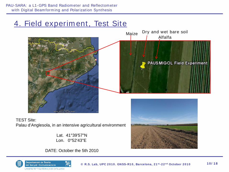
4. Field experiment, Test Site Maize
AlfalfaDry and wet bare soil
TEST Site: Palau d’Anglesola, in an intensive agricultural environment
Lat. 41°39'57"NLon. 0°52'43"E
DATE: October the 5th 2010
11/18© R.S. Lab, UPC 2010. GNSS-R10, Barcelona, 21st-22nd October 2010
PAU-SARA: a L1-GPS Band Radiometer and Reflectometerwith Digital Beamforming and Polarization Synthesis
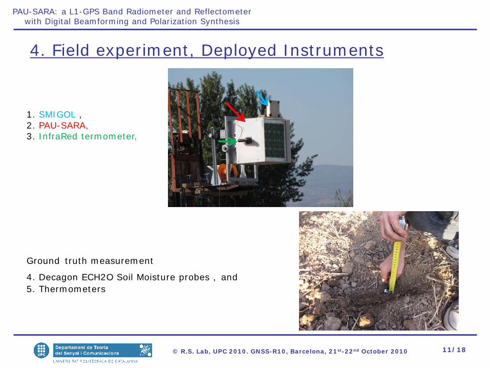
4. Field experiment, Deployed Instruments
1. SMIGOL ,2. PAU-SARA,3. InfraRed termometer,
Ground truth measurement
4. Decagon ECH2O Soil Moisture probes , and5. Thermometers
12/18© R.S. Lab, UPC 2010. GNSS-R10, Barcelona, 21st-22nd October 2010
PAU-SARA: a L1-GPS Band Radiometer and Reflectometerwith Digital Beamforming and Polarization Synthesis
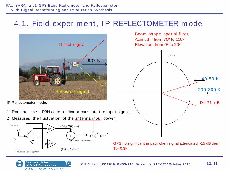
4.1. Field experiment, IP-REFLECTOMETER mode
North
90º N
Direct signal
Reflected signal
Beam shape spatial filter,Azimuth : from 70º to 110ºElevation: from 0º to 20º
D=21 dBIP-Reflectometer mode:
1. Does not use a PRN code replica to correlate the input signal,
2. Measures the fluctuation of the antenna input power,
Complex Correlator
X (SA)2-(SR)
2
g1,n1
g2,n2
(SA+SR)+n1
(SA-SR)+n2Wilkinson Power Splitter
SR
Antenna
SA
200-300 K
40-50 K
GPS no significant impact when signal attenuated >15 dB then Tb<0.3k
13/18© R.S. Lab, UPC 2010. GNSS-R10, Barcelona, 21st-22nd October 2010
PAU-SARA: a L1-GPS Band Radiometer and Reflectometerwith Digital Beamforming and Polarization Synthesis
16.2 16.3 16.4 16.5 16.6 16.7 16.8 16.9150
200
250
300
350
400
450
500
Time
Kel
vin
PAU-SARA pointing to the horizon (East)
AntennahAntennav
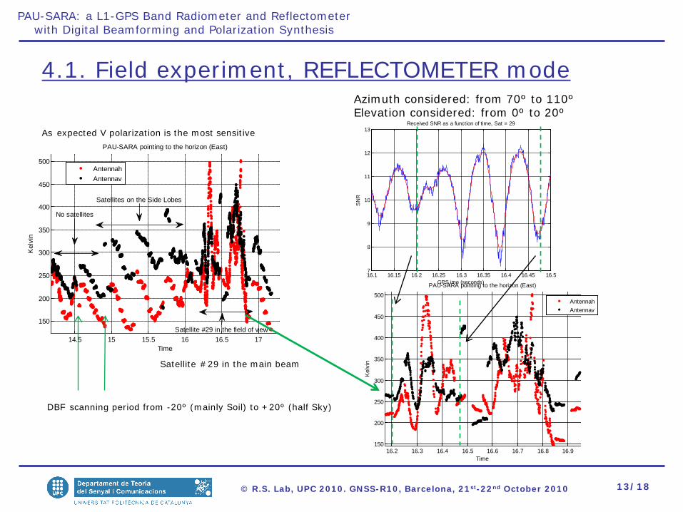
4.1. Field experiment, REFLECTOMETER modeAzimuth considered: from 70º to 110ºElevation considered: from 0º to 20º
16.1 16.15 16.2 16.25 16.3 16.35 16.4 16.45 16.57
8
9
10
11
12
13
GPStime (seconds)
SN
R
Received SNR as a function of time, Sat = 29
14.5 15 15.5 16 16.5 17
150
200
250
300
350
400
450
500
Time
Kel
vin
PAU-SARA pointing to the horizon (East)
AntennahAntennav
No satellites
Satellites on the Side Lobes
Satellite #29 in the field of view
DBF scanning period from -20º (mainly Soil) to +20º (half Sky)
As expected V polarization is the most sensitive
Satellite #29 in the main beam
14/18© R.S. Lab, UPC 2010. GNSS-R10, Barcelona, 21st-22nd October 2010
PAU-SARA: a L1-GPS Band Radiometer and Reflectometerwith Digital Beamforming and Polarization Synthesis
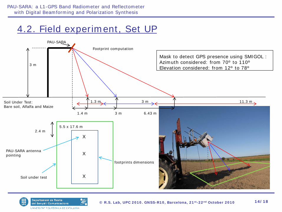
3 m
PAU-SARA
Soil Under Test: Bare soil, Alfalfa and Maize
Footprint computation
1.4 m
5.5 x 17.6 m
X
X
X
2.4 m
PAU-SARA antenna pointing
Soil under test
footprints dimensions
4.2. Field experiment, Set UP
3 m 6.43 m
1.3 m 3 m 11.3 m
Mask to detect GPS presence using SMIGOL :Azimuth considered: from 70º to 110ºElevation considered: from 12º to 78º
15/18© R.S. Lab, UPC 2010. GNSS-R10, Barcelona, 21st-22nd October 2010
PAU-SARA: a L1-GPS Band Radiometer and Reflectometerwith Digital Beamforming and Polarization Synthesis
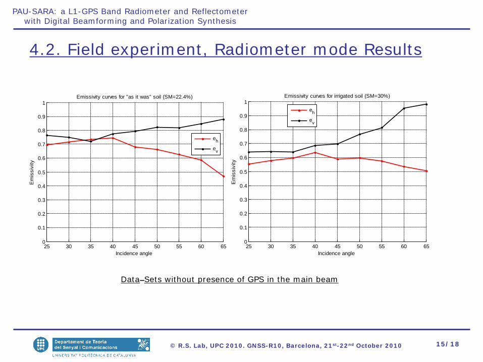
4.2. Field experiment, Radiometer mode Results
Data Sets without presence of GPS in the main beam
25 30 35 40 45 50 55 60 650
0.1
0.2
0.3
0.4
0.5
0.6
0.7
0.8
0.9
1
Incidence angle
Em
issi
vity
Emissivity curves for "as it was" soil (SM=22.4%)
eh
ev
25 30 35 40 45 50 55 60 650
0.1
0.2
0.3
0.4
0.5
0.6
0.7
0.8
0.9
1
Incidence angle
Em
issi
vity
Emissivity curves for irrigated soil (SM=30%)
eh
ev

16/18© R.S. Lab, UPC 2010. GNSS-R10, Barcelona, 21st-22nd October 2010
PAU-SARA: a L1-GPS Band Radiometer and Reflectometerwith Digital Beamforming and Polarization Synthesis
4.2. Field experiment, Radiometer mode Results
Data Setswithout presence of GPS in themain beam
hAlfalfa= 15 cmSM= 25%Tsoil= 287.1 K
hMaize=2.85 mSM= 28%Tsoil= 285.3 K
Maize plants were dry
25 30 35 40 45 50 55 60 650
0.1
0.2
0.3
0.4
0.5
0.6
0.7
0.8
0.9
1
Incidence angle
Em
issi
vity
Emissivity curves for ALFALFA (SM=25%)
eh
ev
25 30 35 40 45 50 55 60 650
0.1
0.2
0.3
0.4
0.5
0.6
0.7
0.8
0.9
1
Incidence angle
Em
issi
vity
Emissivity curves for MAIZE (SM=28%)
eh
ev
17/18© R.S. Lab, UPC 2010. GNSS-R10, Barcelona, 21st-22nd October 2010
PAU-SARA: a L1-GPS Band Radiometer and Reflectometerwith Digital Beamforming and Polarization Synthesis
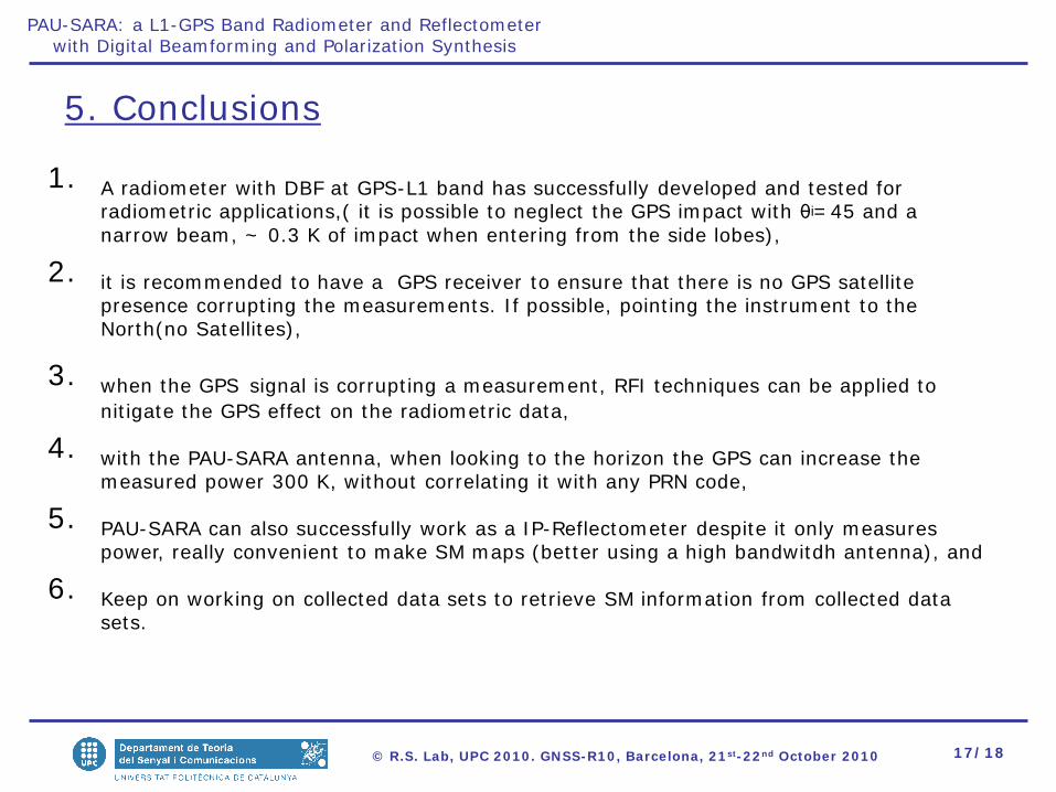
5. Conclusions
1. A radiometer with DBF at GPS-L1 band has successfully developed and tested for radiometric applications,( it is possible to neglect the GPS impact with θi= 45 and a narrow beam, ~ 0.3 K of impact when entering from the side lobes),
2. it is recommended to have a GPS receiver to ensure that there is no GPS satellite presence corrupting the measurements. If possible, pointing the instrument to the North(no Satellites),
3. when the GPS signal is corrupting a measurement, RFI techniques can be applied to nitigate the GPS effect on the radiometric data,
4. with the PAU-SARA antenna, when looking to the horizon the GPS can increase the measured power 300 K, without correlating it with any PRN code,
5. PAU-SARA can also successfully work as a IP-Reflectometer despite it only measures power, really convenient to make SM maps (better using a high bandwitdh antenna), and
6. Keep on working on collected data sets to retrieve SM information from collected data sets.
18/18© R.S. Lab, UPC 2010. GNSS-R10, Barcelona, 21st-22nd October 2010
PAU-SARA: a L1-GPS Band Radiometer and Reflectometerwith Digital Beamforming and Polarization Synthesis
THANK YOU!
19/18© R.S. Lab, UPC 2010. GNSS-R10, Barcelona, 21st-22nd October 2010
PAU-SARA: a L1-GPS Band Radiometer and Reflectometerwith Digital Beamforming and Polarization Synthesis
-80 -60 -40 -20 0 20 40 60 80-30
-25
-20
-15
-10
-5
0
Scanned angle θ (º)
Nor
mal
ized
arra
y fa
ctor
|Sa|2-|Sw|2 for H-pol
0º10º-10º20º-20º
-80 -60 -40 -20 0 20 40 60 80-30
-25
-20
-15
-10
-5
0
SYNTHETIC IMAGE
Angle [degree]
Nor
mal
ized
imag
e re
cons
truci
ton
[dB
]
0o
-10o
-20o
10o
20o
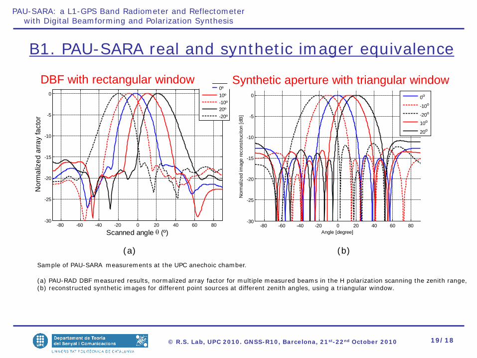
Sample of PAU-SARA measurements at the UPC anechoic chamber.
(a) PAU-RAD DBF measured results, normalized array factor for multiple measured beams in the H polarization scanning the zenith range,(b) reconstructed synthetic images for different point sources at different zenith angles, using a triangular window.
(a) (b)
B1. PAU-SARA real and synthetic imager equivalence
DBF with rectangular window Synthetic aperture with triangular window