part 4 systems and components chapter 3 rotating … 3 rotating machinery - drivers. foreword ......
TRANSCRIPT
The content of this service document is the subject of intellectual property rights reserved by DNV GL AS ("DNV GL"). The useraccepts that it is prohibited by anyone else but DNV GL and/or its licensees to offer and/or perform classification, certificationand/or verification services, including the issuance of certificates and/or declarations of conformity, wholly or partly, on thebasis of and/or pursuant to this document whether free of charge or chargeable, without DNV GL's prior written consent.DNV GL is not responsible for the consequences arising from any use of this document by others.
The electronic pdf version of this document, available free of chargefrom http://www.dnvgl.com, is the officially binding version.
DNV GL AS
RULES FOR CLASSIFICATION
Ships
Edition January 2017
Part 4 Systems and components
Chapter 3 Rotating machinery - drivers

FOREWORD
DNV GL rules for classification contain procedural and technical requirements related to obtainingand retaining a class certificate. The rules represent all requirements adopted by the Society asbasis for classification.
© DNV GL AS January 2017
Any comments may be sent by e-mail to [email protected]
If any person suffers loss or damage which is proved to have been caused by any negligent act or omission of DNV GL, then DNV GL shallpay compensation to such person for his proved direct loss or damage. However, the compensation shall not exceed an amount equal to tentimes the fee charged for the service in question, provided that the maximum compensation shall never exceed USD 2 million.
In this provision "DNV GL" shall mean DNV GL AS, its direct and indirect owners as well as all its affiliates, subsidiaries, directors, officers,employees, agents and any other acting on behalf of DNV GL.

Part
4 C
hapt
er 3
Cha
nges
- c
urre
nt
Rules for classification: Ships — DNVGL-RU-SHIP Pt.4 Ch.3. Edition January 2017 Page 3Rotating machinery - drivers
DNV GL AS
CHANGES – CURRENT
This document supersedes the July 2016 edition.Changes in this document are highlighted in red colour. However, if the changes involve a whole chapter,section or sub-section, normally only the title will be in red colour.
Main changes January 2017, entering into force 1 July 2017
• Sec.1 Reciprocating internal combustion enginesThe section has been updated with requirements related to:
— integration testing as specified in IACS UR M51 Factory Acceptance Test and Shipboard Trials of I.C.Engines
— placement of inlet air ventilators in double walled/ducted gas piping according to the IGF code— simplification of requirements for accumulators unique and standard design.
Editorial correctionsIn addition to the above stated changes, editorial corrections may have been made.

Part
4 C
hapt
er 3
Con
tent
s
Rules for classification: Ships — DNVGL-RU-SHIP Pt.4 Ch.3. Edition January 2017 Page 4Rotating machinery - drivers
DNV GL AS
CONTENTS
Changes – current.................................................................................................. 3
Section 1 Reciprocating internal combustion engines.............................................81 General................................................................................................ 8
1.1 Application....................................................................................... 81.2 Documentation of the engine........................................................... 111.3 Drawing particulars......................................................................... 151.4 Documentation of arrangement........................................................ 161.5 Documentation of vibration.............................................................. 16
2 Design................................................................................................162.1 General..........................................................................................162.2 Approved materials......................................................................... 182.3 Safety valves and crankcase ventilation.............................................192.4 Turning appliances and interlocking device......................................... 202.5 Crankshaft calculation..................................................................... 202.6 Fire protection and general requirements to piping systems fitted onthe engine...........................................................................................222.7 Hydraulic oil system........................................................................232.8 Fuel oil system...............................................................................232.9 Fuel gas system............................................................................. 242.10 Charge air system, blowers and cooler............................................ 242.11 Starting equipment....................................................................... 252.12 Lubrication oil system....................................................................252.13 Cooling system............................................................................. 262.14 Type approval testing.................................................................... 262.15 Type testing data collection............................................................ 262.16 Type testing program.................................................................... 26
3 Testing and inspection.......................................................................313.1 Manufacturing inspections................................................................ 313.2 Testing of materials and components................................................ 313.3 Inspection during assembly..............................................................35
4 Workshop testing...............................................................................354.1 Application..................................................................................... 354.2 General engine tests....................................................................... 364.3 Testing of propulsion engines........................................................... 374.4 Testing of auxiliary driving engines and engines driving electricalgenerators........................................................................................... 38

Part
4 C
hapt
er 3
Con
tent
s
Rules for classification: Ships — DNVGL-RU-SHIP Pt.4 Ch.3. Edition January 2017 Page 5Rotating machinery - drivers
DNV GL AS
4.5 Survey after testing........................................................................ 395 Control and monitoring......................................................................39
5.1 General..........................................................................................395.2 Speed governing.............................................................................405.3 Overspeed protection...................................................................... 415.4 Propulsion engines.......................................................................... 415.5 Auxiliary engines............................................................................ 455.6 Emergency engines......................................................................... 495.7 Oil mist detection/monitoring and alarm system (oil mist detector)........50
6 Arrangement......................................................................................516.1 Engine alignment/seating.................................................................516.2 Accessibility of engines....................................................................516.3 Earthing.........................................................................................526.4 Starting with compressed air............................................................526.5 Electrical starting equipment............................................................ 526.6 Exhaust pipes.................................................................................526.7 Lubrication and fuel oil systems....................................................... 526.8 Crankcase ventilation pipes..............................................................53
7 Vibration............................................................................................ 537.1 Torsional and axial vibration.............................................................53
8 Installation inspections..................................................................... 538.1 Engine seating................................................................................538.2 Engine alignment............................................................................ 53
9 Shipboard testing.............................................................................. 539.1 Shipboard testing (dock and sea trials)............................................. 539.2 General engine tests....................................................................... 539.3 Testing of engines for propulsion and main power supply..................... 549.4 Testing of engines driving auxiliaries................................................. 559.5 Engine vibration..............................................................................559.6 Opening up after testing..................................................................55
10 Gas only and dual fuel engines........................................................5510.1 General........................................................................................5510.2 Design......................................................................................... 5610.3 Testing and inspection................................................................... 6110.4 Workshop testing.......................................................................... 6110.5 Control and monitoring.................................................................. 6110.6 Arrangement.................................................................................6410.7 Vibration...................................................................................... 6410.8 Installations inspections................................................................. 64

Part
4 C
hapt
er 3
Con
tent
s
Rules for classification: Ships — DNVGL-RU-SHIP Pt.4 Ch.3. Edition January 2017 Page 6Rotating machinery - drivers
DNV GL AS
10.9 Shipboard testing..........................................................................6410.10 Retrofit.......................................................................................65
11 Auxiliary equipment and components..............................................6511.1 Turbochargers...............................................................................6511.2 Torsional vibration dampers............................................................7211.3 Axial vibration dampers................................................................. 7311.4 Explosion relief valves................................................................... 73
Section 2 Gas turbines.......................................................................................... 751 General.............................................................................................. 75
1.1 Application..................................................................................... 751.2 Definitions......................................................................................751.3 Certification....................................................................................761.4 Documentation requirements - manufacturer......................................771.5 Documentation requirements – builder.............................................. 81
2 Design and construction.................................................................... 822.1 General..........................................................................................822.2 Component design requirements – manufacturer................................ 842.3 Systems design requirements - package provider/builder..................... 852.4 Enclosure, fire safety.......................................................................89
3 Control and monitoring......................................................................913.1 Gas turbine control......................................................................... 913.2 Monitoring and instrumentation system............................................. 933.3 Auxiliary system controls................................................................. 943.4 Control stations.............................................................................. 94
4 Arrangement......................................................................................944.1 Alignment and reaction forces.......................................................... 944.2 Mounting in general........................................................................ 944.3 Rigid mounting............................................................................... 954.4 Resilient mounting.......................................................................... 96
5 System vibration................................................................................965.1 General..........................................................................................965.2 Documentation of vibration analysis.................................................. 965.3 Gas turbine vibration.......................................................................97
6 Tests and trials..................................................................................986.1 Tests, general.................................................................................986.2 Testing of material and components..................................................996.3 Tests on components (manufacturer’s works)................................... 1006.4 Type approval test (manufacturer’s works)....................................... 101

Part
4 C
hapt
er 3
Con
tent
s
Rules for classification: Ships — DNVGL-RU-SHIP Pt.4 Ch.3. Edition January 2017 Page 7Rotating machinery - drivers
DNV GL AS
6.5 Type testing program.................................................................... 1026.6 Inspection of condition of parts (Borescope/tear down)...................... 1046.7 Certification testing (FAT, manufacturer’s works)............................... 1056.8 Certification test program.............................................................. 1066.9 Inspection of condition of parts (Borescope)..................................... 1076.10 Shipboard trials...........................................................................107
Section 3 Steam turbines.................................................................................... 1101 General............................................................................................ 110
1.1 Application................................................................................... 1101.2 Certification requirements.............................................................. 1101.3 Documentation requirements - manufacturer....................................1101.4 Documentation requirements - builder............................................. 111
2 Design..............................................................................................1112.1 General........................................................................................1112.2 Component design requirements.....................................................112
3 Inspection and testing.....................................................................1123.1 General........................................................................................112
4 Workshop testing.............................................................................1134.1 General turbine tests.....................................................................113
5 Control and monitoring....................................................................1145.1 General........................................................................................1145.2 Speed governing........................................................................... 1145.3 Safety functions and devices.......................................................... 1145.4 Monitoring.................................................................................... 115
6 Arrangement....................................................................................1176.1 General arrangement.....................................................................1176.2 Arrangement of propulsion machinery..............................................118
7 Vibrations........................................................................................ 1187.1 Torsional vibrations....................................................................... 118
8 Installation inspections................................................................... 1198.1 General........................................................................................119
9 Shipboard testing............................................................................ 1199.1 General........................................................................................1199.2 Auxiliary turbines.......................................................................... 1199.3 Propulsion turbines........................................................................119
Changes – historic.............................................................................................. 120

Part
4 C
hapt
er 3
Sec
tion
1
Rules for classification: Ships — DNVGL-RU-SHIP Pt.4 Ch.3. Edition January 2017 Page 8Rotating machinery - drivers
DNV GL AS
SECTION 1 RECIPROCATING INTERNAL COMBUSTION ENGINES
1 General
1.1 Application
1.1.1 The requirements in this section apply to all reciprocating internal combustion engines installed onDNV GL classed ships.Reciprocating internal combustion engine used for main functions listed in Pt.1 Ch.1 Sec.1 Table 2 oremergency duty are subject to approval, certification, installation survey and shipboard testing according tothese rules.
1.1.2 Reciprocating internal combustion engine in this section is referred to as engine.
1.1.3 For the purpose of these requirements, engines are:
— diesel engines, fuelled with liquid fuel oil— dual-fuel engines, fuelled with liquid fuel oil and/or with gaseous fuel— gas-only engines, fuelled with gaseous fuel only and ignited by either a spark or micropilot of liquid fuel
oil.
1.1.4 Depending on engine speed, engines are divided into:
— low-speed engines means engines having a rated speed of less than 300 rpm— medium-speed engines means engines having a rated speed of 300 rpm and above, but less than 1400
rpm— high-speed engines means engines having a rated speed of 1400 rpm or above.
1.1.5 Definition of engine typeThe type specification of an engine is defined by the following data:
— manufacturer's type designation— cylinder bore— stroke— method of injection (direct, indirect)— valve and injection operation (by cams or electronically controlled)— fuels which can be used (liquid, dual-fuel, gaseous)— working cycle (4-stroke, 2-stroke)— method of gas exchange (naturally aspirated or supercharged)— rated power per cylinder at rated speed as well as mean effective pressure, see [2.1.8]— method of pressure charging (pulsating pressure system or constant-pressure charging system)— charge air cooling system (with or without intercooler, number of stages)— cylinder arrangement (in-line, vee).
1.1.6 Diesel engines used for main function or emergency duty with power less than 100 kW, therequirements in this section are limited to the below listed items:
1) insulation of hot surfaces, see [2.6]2) jacketing of high-pressure fuel oil lines, see [2.8.7]3) screening of pipe connections in piping containing flammable liquids, see [2.6] and [2.8]4) requirements for starting equipment if applicable, see [2.11.3] and [2.11.4]5) requirements for type testing as given in [2.14.2]6) requirements for workshop testing as given in [4.1.6]

Part
4 C
hapt
er 3
Sec
tion
1
Rules for classification: Ships — DNVGL-RU-SHIP Pt.4 Ch.3. Edition January 2017 Page 9Rotating machinery - drivers
DNV GL AS
7) requirements for control and monitoring according to [5.6], except for emergency fire-extinguishing sets,shut down due to low lubricating oil pressure according to Table 9 to be provided.
8) requirements for shipboard testing as given in [9]9) certification required according to [1.1.13].
For dual-fuel and gas-only engines additional requirements in [10] apply.
1.1.7 Engines used neither for main functions nor emergency dutyDiesel engines used neither for main functions nor emergency duty, the requirements in this section arelimited to [1.1.6] 1), 2), 3) and 9).Compliance shall be demonstrated during shipboard testing.For dual-fuel and gas-only engines additional requirements in [10] apply.
Guidance note:These engines can be type approved based on the same document requirements as applicable for diesel engines used for mainfunctions.
---e-n-d---o-f---g-u-i-d-a-n-c-e---n-o-t-e---
1.1.8 Type testingEngines shall be type tested according to requirements stated in this section.For more information regarding the Society's type approval scheme, see DNVGL-CG-0338.
1.1.9 In case of engines intended for vessels approved for unmanned machinery installations (class notationE0), Pt.6 Ch.2 Sec.2 apply in addition to the requirements in this section.
1.1.10 For all engine installations intended for running on crude oil or gas, additional requirements are givenin Pt.6 Ch.2 Sec.5 and Pt.6 Ch.2 Sec.6.
1.1.11 Regarding the use of marine fuels with a sulphur content not exceeding 0.1% m/m and minimumviscosity of 2 cSt the engine manufacturer’s recommendations with respect to e.g. fuel change-over process,lubricity, viscosity and compatibility shall be described in the operation manual.
1.1.12 The rules in [2] to [5] apply to the engine, its components and its internal systems. The rules in [6]to [9] apply to the installation of the engine, the engine and its system dynamics, which are influenced bythe engine, and the shipboard testing.

Part
4 C
hapt
er 3
Sec
tion
1
Rules for classification: Ships — DNVGL-RU-SHIP Pt.4 Ch.3. Edition January 2017 Page 10Rotating machinery - drivers
DNV GL AS
1.1.13 Certification requirementsEngines shall be delivered with a product certificate according to Table 1.
Table 1 Certification required
Object Certificatetype
Issued by Additional description
Dieselengine PC Society
P ≥ 300 kW
Engines used for main function or emergency duty
Dieselengine
TA
(PC)
Society
(Society)
100 kW < P < 300 kW
Engines used for main function or emergency duty
(Equipment not having valid type approval certificate may be acceptedon the basis of a DNV GL product certificate)
Dieselengine
TA
(PC)
Society
(Manufacturer)
P ≤ 100 kW
Engines used for main function or emergency duty
(Equipment not having valid type approval certificate may be acceptedon the basis of a product certificate issued by the manufacturer)
Dieselengine
TA
(PC)
Society
(Manufacturer)
All engines not used for main function nor emergency
(Equipment not having valid type approval certificate may be acceptedon the basis of a product certificate issued by the manufacturer)
Gas fuelledengine PC Society All
Certification standard is the DNV GL rules.
PC or MC issued by the Society (based on the DNV GL rules) = VL certificate (see Pt.1 Ch.3 Sec.5).
PC or MC issued by the manufacturer (based on the DNV GL rules) = works certificate (see Pt.1 Ch.3 Sec.5).
For general certification requirements see Pt.1 Ch.3 Sec.4.For a definition of the certification types see Pt.1 Ch.3 Sec.5.
1.1.14 Engines manufactured under licenseFor engines manufactured under licence, the licensee shall submit the following documents for approval:
— comparison of all the drawings and documents as per Table 2 - Table 5, where applicable, indicating therelevant drawings used by the licensee and the licensor
— all drawings of modified components, as per Table 2 - Table 5 together with the licensor's declaration ofconsent to the modifications
— a complete set of approved drawings or list of approved drawing shall be put at the disposal of the localinspection office of the Society as a basis for the performance of tests and inspections. This shall includethe drawings marked "P" in the info column in Table 2.
1.1.15 Engines manufactured under manufacturing survey arrangementTrunk engines which will be manufactured in mass or in series, can be produced according to agreedmanufacturing survey arrangement (MSA). More information can be found in DNV GL class guideline DNVGL-CP-0483 Mass and serial produced engines - Alternative product certification scheme.
1.1.15.1 Document requirements for engines manufactured under MSAEngine types that shall be produced according to a MSA, shall be documented with DNV GL data sheetENG921 in addition to the requirements in these rules.

Part
4 C
hapt
er 3
Sec
tion
1
Rules for classification: Ships — DNVGL-RU-SHIP Pt.4 Ch.3. Edition January 2017 Page 11Rotating machinery - drivers
DNV GL AS
1.2 Documentation of the engine1.2.1 GeneralDrawings, data, specifications, calculations and other information shall be submitted as applicable accordingto Table 2, Table 3 and Table 4, except for items covered by a valid type approval.Documentation listed in Table 2 - Table 4 marked with a "P" in the info field, are additional documentationrequired to be submitted if production applies for the facility.
1.2.2 Design modificationsFollowing initial approval of an engine type by the Society, only those documents listed in Table 2 to Table 4which embodies design modifications shall be resubmitted for approval.
1.2.3 Approval of engine componentsThe manufacturers shall request approval from the Society for exhaust gas turbochargers, torsional vibrationdampers, crankcase relief valves etc, see [11] for more information. For oil mist detectors see [5.7].
Table 2 Documentation of engine fuelled by liquid fuel oil
No. Additional description Documentation type Info
01 Engine particulars, Society forms ENG 901, ENG 911 and ENG921 Z110 – Data sheet FITA)
02 Engine cross section C020 – Assembly or arrangement drawing FITA)
03 Engine longitudinal section C020 – Assembly or arrangement drawing FITA)
04
Bedplate and crankcase/engine block
— cast— welded design, with welding details and welding instructions
1)
C020 – Assembly or arrangement drawing
C030 – Detailed drawing
FI TA)
APTA)
05 Thrust bearing assembly2) C030 – Detailed drawing FITA)
06
Thrust bearing bedplate
— cast— welded design, with welding details and welding instructions
2)
C020 – Assembly or arrangement drawing
C030 – Detailed drawing
FITA)
APTA)
07
Frame/framebox/cylinder jacket/block/gearbox
— cast— welded design, with welding details and instructions 1) 3)
C020 – Assembly or arrangement drawing
C030 – Detailed drawing
FITA)
APTA)
08 Tie rod C030 – Detailed drawing FITA)
09Cylinder cover/head, assembly 4)
Cylinder cover/head
C020 – Assembly or arrangement drawing
C030 – Detailed drawing
FITA)
APP)
10 Cylinder liner 4) C030 – Detailed drawing FITA)
11Crankshaft details, each cylinder number [2.5]- data sheet for calculation of crankshaft stress
C030 – Detailed drawing
Z110 – Datasheet
APTA)
FITA)
12 Crankshaft assembly for each number of cylinders [2.5] C020 – Assembly or arrangement drawing APTA)
13 Thrust shaft or intermediate shaft, if integrated in the engine C030 – Detailed drawing APTA)

Part
4 C
hapt
er 3
Sec
tion
1
Rules for classification: Ships — DNVGL-RU-SHIP Pt.4 Ch.3. Edition January 2017 Page 12Rotating machinery - drivers
DNV GL AS
No. Additional description Documentation type Info
14 Shaft coupling bolts [2.5] C030 – Detailed drawing APTA)
15Counter weight (if not integral with crankshaft)- including fastening 4)
C030 – Detailed drawingC020 – Assembly or arrangement drawing
FITA)
FITA)
16 Connecting rod 4) C030 – Detailed drawing FITA)
17 Connecting rod, assembly 4) 5) C020 – Assembly or arrangement drawing FITA)
18Crossheads, assembly 5)
- crossheadC020 – Assembly or arrangement drawingC030 – Detailed drawing
FITA)
APP)
19Piston rod assembly 5)
- piston rodC020 – Assembly or arrangement drawingC030 – Detailed drawing
FITA)
APP)
20Piston, assembly 4) 5)
- piston crown/headC020 – Assembly or arrangement drawingC030 – Detailed drawing
FITA)
APP)
21 Camshaft arrangement and high pressure pump drive, assembly4) 5) C020 – Assembly or arrangement drawing FITA)
22 Material data for engine main parts with information on non-destructive material tests and pressure tests 6) [2.2] M010 – Material specification, metals APTA)
23 Arrangement of foundation (for main engines only) [1.4] C020 – Assembly or arrangement drawing FIP)
24 Schematic layout or other equivalent documents of the startingair system 7) [1.3.2], [2.11] S015 – Piping system schematic layout APTA)
25 Schematic layout or other equivalent documents of the fuel oilsystem 7) [1.3.2], [2.8] S015 – Piping system schematic layout APTA)
26 Schematic layout or other equivalent documents of thelubrication oil system 7) [1.3.2], [2.12] S015 – Piping system schematic layout APTA)
27 Schematic layout or other equivalent documents of the coolingwater system 7) [1.3.2], [2.13] S015 – Piping system schematic layout APTA)
28Schematic diagram of engine control and safety system,including list of set points of required alarms and shutdowns 8)
[5]
I200 – Control and monitoring systemdocumentation APTA)
29Schematic diagram of engine electronic components, systemsand FMEA, including list of set points of required alarms andshutdowns 8) [5]
I200 – Control and monitoring systemdocumentation APTA)
30 Shielding and insulation of the exhaust system [2.6.1] C020 – Assembly or arrangement drawing FITA)
31 Shielding of high pressure parts containing flammable liquids,assembly [2.8.7] C020 – Assembly or arrangement drawing APTA)
32 Crankcase explosion relief valves, arrangement an details 9)
[1.3.1], [2.3] C020 – Assembly or arrangement drawing APTA)
33Operation manual 10)
and Maintenance manual 10)Z161 – Operation manualZ163 – Maintenance manual
FITA)
FITA)
34 Schematic layout or other equivalent documents of hydraulicsystem on the engine 7) [1.3.5], [2.7] C020 – Assembly or arrangement drawing APTA)

Part
4 C
hapt
er 3
Sec
tion
1
Rules for classification: Ships — DNVGL-RU-SHIP Pt.4 Ch.3. Edition January 2017 Page 13Rotating machinery - drivers
DNV GL AS
No. Additional description Documentation type Info
35Type approval test program andType approval report
[2.14] to [2.16] and [1.3.6]
Z252 – Test procedure at manufacturerZ262 – Report from test at manufacturer
APTA)
APTA)
36
High pressure parts for fuel oil injection system 11)
— high-pressure pumps— control valves— bodies— accumulators for hydraulic oil and fuel oil, see [2.6.9]— piping with connections
C020 – Assembly or arrangement drawing
C020 – Assembly or arrangement drawing
C030 – Detailed drawing
C020 – Assembly or arrangement drawing
C020 – Assembly or arrangement drawing
FITA)
FITA)
APTA)
APTA)
APTA)
37 Arrangement of oil mist detection and/or alternative alarmarrangements, monitoring and alarm system 12) [5.7] C020 – Assembly or arrangement drawing APTA)
38 Schematic layout or other equivalent documents of Exhaust andcharge air system 7) [1.3.2], [2.10] C020 – Assembly or arrangement drawing APTA)
39 Documentation of vibration, mass elastic data and excitationvalues [1.5], Ch.2 Sec.2 C040 – Design analysis FITA)
40 Flywheel C020 – Assembly or arrangement drawing FITA)
41 Construction and arrangement of torsional vibration dampers C020 – Assembly or arrangement drawing FITA)
42
Bolt and studs
— for main bearings— for cylinder heads and exhaust valve (two stroke design)— for connecting rods
C030 – Detailed drawing
C030 – Detailed drawing
C030 – Detailed drawing
APP)
APP)
APP)
43 Integration test program 8) [1.3.6] Z252 – Test procedure at manufacturer APTA)
Table 3 Additional documentation for gas fuelled engines, see [10]
No. Additional description Documentation type Info
44 Functional description of gas fuelled engine Z060 – Functional description FITA)
45 Engine safety concept, including system FMEA with regard togas as fuel
Z071 – Failure mode and effect analysis(FMEA) FITA)
46
Fuel gas system including double wall piping and ventilationsystem 8) [10.2.9]
— schematic layout of fuel gas system 7)
— schematic layout of ventilation system 7)
— fuel gas system— fuel gas piping and flange design
S015 – Piping system schematic layout
S015 – Piping system schematic layout
C020 – Assembly or arrangement drawing
C030 – Detailed drawing
APTA)
APTA)
FITA)
APTA)
47
Charge air system [10.2.6]:
— documentation of sufficient strength if relief valve is notinstalled arrangement
— relief valve arrangement if installed
Z265 – Calculation report
C020 – Assembly or arrangement drawing
APTA)
APTA)
Part
4 C
hapt
er 3
Sec
tion
1
Rules for classification: Ships — DNVGL-RU-SHIP Pt.4 Ch.3. Edition January 2017 Page 14Rotating machinery - drivers
DNV GL AS
No. Additional description Documentation type Info
48
Engine exhaust gas system:
— documentation of sufficient strength if relief valve is notinstalled arrangement [10.2.6]
— relief valve arrangement if installed [10.2.6]
Z265 – Calculation report
S015 – Piping system schematic layout
APTA)
APTA)
49 Testing procedure for gas detection system [10.4] Z252 – Test procedure at manufacturer FITA)
50 Testing procedure for gas tightness [10.4] Z252 – Test procedure at manufacturer FITA)
Table 4 Additional documentation for auxiliary equipment and components
Object Additional description Documentation type Info
Turbocharger 13) [11.1] APTA)
Torsional vibrationdamper [11.2] APTA)
Axial vibration damper [11.3] FITA)
Alarm and monitoring, see [5] I200 – Control and monitoring systemdocumentation AP
Safety system, see [5] I200 – Control and monitoring systemdocumentation AP
Speed control/governor/combustion, see [5]
I200 – Control and monitoring systemdocumentation AP
Engine
Gas valve unit (GVU), see Pt.6 Ch.2Sec.5
I200 – Control and monitoring systemdocumentation AP

Part
4 C
hapt
er 3
Sec
tion
1
Rules for classification: Ships — DNVGL-RU-SHIP Pt.4 Ch.3. Edition January 2017 Page 15Rotating machinery - drivers
DNV GL AS
Table 5 Remarks to Table 2 - Table 4
TA = Covered by type approval
AP = For approval
FI = For information
P = Required if engine production applies
1) The welding procedure specification shall include details of pre and post weld heat treatment, welding consumablesand fit-up conditions
2) If integrated with engine and not in the bedplate3) Only for one cylinder4) Applies to engines with cylinder diameter > 150 mm5) Only necessary if sufficient details are not shown on the transverse cross section and longitudinal section6) For comparison with the Society requirements for material, NDT and pressure testing as applicable7) Integrated in engine design and the auxiliary system8) If engines incorporate electronic control systems a failure mode and effect analysis (FMEA) shall be submitted
to demonstrate that failure of an electronic control system shall not result in any significant reduction of engineperformance
9) Only for engines with bore ≥ 200 mm, or a crankcase volume ≥ 0.6 m3
10) Operation and service manuals shall contain maintenance requirements (servicing and repair) including details ofany special tools and gauges that shall be used with their fitting/settings together with any test requirements oncompletion of maintenance
11) The documentation has to contain specifications of pressures, pipe dimensions and materials12) Only for engines with bore > 300 mm, or a total engine break power of 2250 kW13) Shall be type approved, either as a separate component or as an integral part of the diesel engine. Not applicable to
turbochargers serving cylinder groups with combined power less than or equal to 1000 kW
1.2.4 For general requirements for documentation, including definition of the info codes, see Pt.1 Ch.3 Sec.2.
1.2.5 For a full definition of the documentation types, see Pt.1 Ch.3 Sec.3.
1.2.6 For details about non-destructive testing (NDT) specification, see Ch.2 Sec.1 [3.1.2].
1.3 Drawing particulars1.3.1 Crankcase relief valve arrangementThe documentation of crankcase relief valve arrangement shall indicate
— make and type of valves— the number of valves— their position— the free area of the relief valves— the crankcase volume.
1.3.2 Starting and charge air, fuel-, lubrication-, hydraulic- and cooling water systemsThe schematic drawing of the charge air, fuel oil, lubrication oil, cooling water and hydraulic oil systems onlyneed to show design pressures and required pumps/blowers, valves, filters and sensors. For starting airsystem the safety devices shall be shown, if applicable.
1.3.3 TurbochargersTurbochargers are usually type approved separately, but may also be approved as part of the engine. Samedocument requirements apply. See [11.1] for requirements regarding documentation, design and testing.

Part
4 C
hapt
er 3
Sec
tion
1
Rules for classification: Ships — DNVGL-RU-SHIP Pt.4 Ch.3. Edition January 2017 Page 16Rotating machinery - drivers
DNV GL AS
1.3.4 Electronic components and systemsElectronic components and systems which are necessary for the control of engines shall be approvedaccording to [5] and Ch.9.
1.3.5 Electronic engine management systemElectronic engine management system is a collective term for electronic systems governing fuel oil injection,exhaust valve operation, operation of high pressure fuel oil injection pumps etc.The documentation required per Table 2 and Table 3 shall provide a principal description of the system(s) aswell as reference to valid type approval certificates for the associated software and hardware.In case of a failure of an electronic control system, the equipment shall enter a safe state defined andproven by a structured analysis (e.g. FMEA), which has to be provided by the electronic engine managementsystem's manufacturer. This analysis shall include all possible failure modes and effects.
1.3.6 Integration testIntegration test is applicable to engines which do not have mechanical control of cylinder valves and/or fuelinjection. These tests shall verify that any failure in the control system for the cylinder valves and/or the fuelinjection, do not result in insufficient reliability or unacceptable engine performance. The integration testprogram shall be proposed by the designer and be based on the FMEA Table 2.
1.4 Documentation of arrangementThe following plans and particulars shall be in accordance with the engine designer/manufacturer'sspecifications and be submitted by the builder for approval:
1) Foundation/seating arrangement , see Ch.2 Sec.1 [6].2) Top stay arrangement, if applicable, including reaction forces. See Ch.2 Sec.1 [6].
Resilient mounts used under engines, to be type approved by the society, see DNVGL-CP-0144 Flexiblemounts used for propulsion or auxiliary machinery.
1.5 Documentation of vibrationMass elastic data and table of excitations shall be included in the documentation as information, either as anappendix to the datasheet, a separate document or as an example of a torsional vibration calculation. Alsosee Ch.2 Sec.2.
2 Design
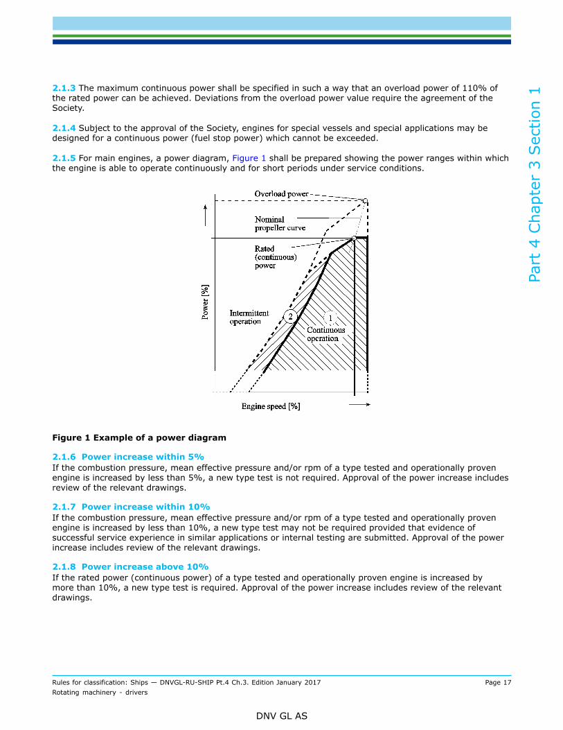
2.1 General2.1.1 Rated powerEngines shall be designed such that their rated power when running at rated speed can be delivered as acontinuous power. This shall be done in accordance with the specifications of the engine manufacturer atambient conditions as defined in Ch.1 Sec.3 [2.2]. Engines shall be capable of operating continuously withinpower range in Figure 1 and intermittently in power range . The extent of the power ranges shall bespecified by the engine manufacturer.
2.1.2 Maximum continuous power shall be understood as the standard service power which an engine iscapable of delivering continuously, provided that the maintenance is carried out as stated by the enginemanufacturer.
Part
4 C
hapt
er 3
Sec
tion
1
Rules for classification: Ships — DNVGL-RU-SHIP Pt.4 Ch.3. Edition January 2017 Page 17Rotating machinery - drivers
DNV GL AS
2.1.3 The maximum continuous power shall be specified in such a way that an overload power of 110% ofthe rated power can be achieved. Deviations from the overload power value require the agreement of theSociety.
2.1.4 Subject to the approval of the Society, engines for special vessels and special applications may bedesigned for a continuous power (fuel stop power) which cannot be exceeded.
2.1.5 For main engines, a power diagram, Figure 1 shall be prepared showing the power ranges within whichthe engine is able to operate continuously and for short periods under service conditions.
Figure 1 Example of a power diagram
2.1.6 Power increase within 5%If the combustion pressure, mean effective pressure and/or rpm of a type tested and operationally provenengine is increased by less than 5%, a new type test is not required. Approval of the power increase includesreview of the relevant drawings.
2.1.7 Power increase within 10%If the combustion pressure, mean effective pressure and/or rpm of a type tested and operationally provenengine is increased by less than 10%, a new type test may not be required provided that evidence ofsuccessful service experience in similar applications or internal testing are submitted. Approval of the powerincrease includes review of the relevant drawings.
2.1.8 Power increase above 10%If the rated power (continuous power) of a type tested and operationally proven engine is increased bymore than 10%, a new type test is required. Approval of the power increase includes review of the relevantdrawings.

Part
4 C
hapt
er 3
Sec
tion
1
Rules for classification: Ships — DNVGL-RU-SHIP Pt.4 Ch.3. Edition January 2017 Page 18Rotating machinery - drivers
DNV GL AS
2.1.9 De-rated engine used to document higher power within 10%If an engine has been design approved, and internal testing per stage A is documented to a rating higherthan the one type tested, the type approval may be extended to the increased power/mep/rpm uponsubmission of an extended delivery test report including:
— test at over speed (only if nominal speed has increased)— rated power, i.e. 100% output at 100% torque and 100% speed corresponding to load point 1, two
measurements with one running hour in between— maximum permissible torque (normally 110%) at 100% speed corresponding to load point 3 or maximum
permissible power (normally 110%) and speed according to nominal propeller curve corresponding to loadpoint 3a, for at least 30 min
— 100% power at maximum permissible speed corresponding to load point 2, for at least 30 min.
2.2 Approved materials
2.2.1 The mechanical characteristics of materials used for the components of engines shall conform to Pt.2Ch.2.The materials approved for the various components are shown in Table 6 together with the minimumrequired characteristics.
Table 6 Approved materials
Approved materials Society's rules Components
Pt.2 Ch.2 Sec.6 [4] Crankshafts
Forged steel Rm ≥ 360 N/mm2
Pt.2 Ch.2 Sec.6 [3]
Connecting rods
Pistons rods
Crossheads
Pistons and piston crowns
Cylinder covers/heads
Camshaft drive wheels
Rolled or forged steel rounds Rm ≥ 360 N/mm2 Pt.2 Ch.2 Sec.6 [9]Tie rodsBolts and studs
Special grade cast steel Rm ≥ 440 N/mm2 and Pt.2 Ch.2 Sec.8 [3]
Special grade forged steel Rm ≥ 440 N/mm2 Pt.2 Ch.2 Sec.6 [4]Throws and webs of built-up crankshafts
Cast steel Pt.2 Ch.2 Sec.8 [3]
Bearing transverse girders (viewable)
Pistons and piston crowns
Cylinder covers/heads
Camshaft drive wheels
Nodular cast iron, preferably ferritic grades Rm ≥350 N/mm2 Pt.2 Ch.2 Sec.9 [2]
Engine blocks
Bedplates
Cylinder blocks
Pistons and piston crowns
Cylinder covers/heads
Flywheels
Valve bodies

Part
4 C
hapt
er 3
Sec
tion
1
Rules for classification: Ships — DNVGL-RU-SHIP Pt.4 Ch.3. Edition January 2017 Page 19Rotating machinery - drivers
DNV GL AS
Approved materials Society's rules Components
Lamellar/grey cast iron Rm ≥ 200 N/mm2 Pt.2 Ch.2 Sec.9 [3]
Engine blocks
Bedplates
Cylinder blocks
Cylinder liners
Cylinder covers/heads
Flywheels
Structural steel, all the Society’s steel grades forplate thickness ≤ 35 mm
Structural steel, the Society’s steel grades VLB forplate thickness > 35 mm
Pt.2 Ch.2 Sec.2 [3],Pt.2 Ch.2 Sec.2 [4]
Structural steel, unalloyed, for welded assemblies Pt.2 Ch.2 Sec.2 [3]
Welded cylinder blocks
Welded bedplates
Welded frames
Welded housings
2.2.2 Materials with properties deviating from the requirements specified may be used only with theSociety’s explicit permission. The Society requires proof of the suitability of such materials.
2.3 Safety valves and crankcase ventilation2.3.1 Crankcase safety relief valvesCrankcase safety relief valves to safeguard against overpressure in the crankcase shall be fitted to all engineswith a cylinder bore of ≥ 200 mm or a crankcase volume of ≥ 0.6 m3.All separated spaces within the crankcase, e.g. gear or chain casings for camshafts or similar drives, shall beequipped with additional safety devices if the volume of these spaces exceeds 0.6 m3.
Table 7 Crankcase safety relief valves
Cylinder diameter D (mm)/crankcase volume V (m3)
Number ofcrank-throws Number of safety relief valves
200 ≤ D ≤ 250 or V > 0.6 ≤ 8 One near each end of the engine
200 ≤ D ≤ 250 > 8 As above plus one near the middle of the engine
250 < D ≤ 300 One in way of each alternate crank-throw, minimum 2
D > 300 One in way of each crank-throw
2.3.2 Relief valvesCrankcase safety relief valves shall be approved according to [11.4].
2.3.3 The free area of each crankcase safety relief valve shall not be less than 45 cm2. The combined freearea of the valves fitted on an engine shall not be less than 115 cm2/m3 of the crankcase gross volume.
Guidance note 1:Each one of the crankcase safety relief valves required to be fitted, may be replaced by not more than two crankcase safety reliefvalves of smaller area, provided that the free area of each valve is not less than 45 cm2.
---e-n-d---o-f---g-u-i-d-a-n-c-e---n-o-t-e---

Part
4 C
hapt
er 3
Sec
tion
1
Rules for classification: Ships — DNVGL-RU-SHIP Pt.4 Ch.3. Edition January 2017 Page 20Rotating machinery - drivers
DNV GL AS
Guidance note 2:The total volume of stationary parts within the crankcase may be discounted in estimating the crankcase gross volume (rotatingand reciprocating components should be included in the gross volume).
---e-n-d---o-f---g-u-i-d-a-n-c-e---n-o-t-e---
Guidance note 3:A space communicating with the crankcase via a total free cross-sectional area of > 115 cm2/m3 of volume need not be consideredas a separate space.
---e-n-d---o-f---g-u-i-d-a-n-c-e---n-o-t-e---
2.3.4 Safety devices shall be provided with a manufacturer’s installation and maintenance manual that ispertinent to the size and type of device as well as on the installation on the engine. A copy of this manualshall be kept on board of the ship.
2.3.5 Crankcase airing and ventingThe airing of crankcases and any arrangement which could produce air intake within the crankcase is inprinciple not allowed.Where crankcase venting systems are provided, their clear opening shall be dimensioned as small aspractically possible.Where provision has been made for forced extracting of lubrication oil mist, e.g. for monitoring the oil mistconcentration, the vacuum in the crankcase shall not exceed 2.5 mbar.In case of two-stroke engines the lubrication oil mist from the crankcase shall not be admitted into thescavenge manifolds respectively the air intake pipes of the engine.
2.3.6 Warning noticeA signboard shall be fitted either on the control stand or, preferably, on a crankcase door on each side ofthe engine. It shall specify that the crankcase doors or sight holes, in case of detected oil mist, shall not beopened before a reasonable time has passed. The time shall be sufficient to permit adequate cooling afterstopping the engine.
2.3.7 Crankcase doors and sight holesCrankcase doors and their fittings shall be so dimensioned as not to suffer permanent deformation due to theoverpressure occurring during the time needed for the safety equipment to respond.
2.3.8 Crankcase doors and hinged inspection ports shall be equipped with appropriate latches to effectivelyprevent unintended closing.
2.4 Turning appliances and interlocking device
2.4.1 Engines shall be equipped with suitable and adequately dimensioned turning appliances.
2.4.2 The turning appliances shall be of the self-locking type.
2.4.3 An automatic interlocking device shall be provided to ensure that the engines cannot start up while theturning gear is engaged.
2.5 Crankshaft calculation2.5.1 Design methodsCrankshafts shall be designed to withstand the stresses occurring when the engine runs at rated power andspeed. Calculations shall be based on the class guideline DNVGL-CG-0037 Calculation of crankshafts forreciprocating internal combustion engines.

Part
4 C
hapt
er 3
Sec
tion
1
Rules for classification: Ships — DNVGL-RU-SHIP Pt.4 Ch.3. Edition January 2017 Page 21Rotating machinery - drivers
DNV GL AS
Other methods of calculation may be used provided that they do not result in dimensions smaller than thoseobtained by applying the aforementioned class guideline.
2.5.2 Maximum nominal altering torsional stressThe maker of the engine shall apply for approval of a maximal additional (vibratory) shear stress, which isreferred to the crank with the highest load due to mean torque and bending forces.This approved additional shear stress may be applied for first evaluation of the calculated vibratory stressesin the crankshaft via the torsional vibration model. Common values are between 30 and 70 N/mm2 formedium and high speed engines and between 25 and 40 N/mm2 for two stroke engines, but specialconfirmation of the value considered for judgement by the Society is necessary. For further details, see Ch.2Sec.2.
2.5.3 When the approved limit for the vibratory stresses for the crankshaft of the engine as definedunder [2.5.2] is exceeded, special considerations may be applied to define a higher limit for the specialinvestigated case. For this detailed system calculations (combined axial/torsional model) and application ofthe actual calculated data within the model in accordance to the class guideline DNVGL-CG-0037, as quotedunder [2.5.1] are necessary. Such special considerations, especially the application of combined axial andtorsional vibration calculations, may only be considered for direct coupled two stroke engine plants. For suchevaluations the acceptability factor in accordance to [2.5.2] shall in no case be less than 1.15 over the wholespeed range.
2.5.4 Class guideline DNVGL-CG-0037 also contains requirements for safety versus slippage of semi-builtcrankshafts. (Fully built crankshafts shall be considered on basis of equivalence with these requirements.)The required minimum safety factor against slippage is 2.0. This is valid for the highest peak torque in thecrankshaft and also taking the shrink fitting procedure into account. The maximum shrinkage amount islimited by the permissible amount of plastification of the web and journal materials.
2.5.5 Split crankshaftsOnly fitted bolts shall be used for assembling split crankshafts.
2.5.6 Power-end flange couplingsThe bolts used to connect power-end flange couplings shall be designed as fitted bolts in accordance withCh.4 Sec.1 [1.2.3].If the use of fitted bolts is not feasible, the Society may agree to the use of an equivalent frictional resistancetransmission. In these cases the corresponding calculations shall be submitted for approval.
2.5.7 Impact torque due to operation in iceFor direct coupled propulsion engines (i.e. no elastic coupling) in ships with class notations ICE or PC,the crankshaft and the crankshaft bolts shall be designed for the ice impact torques. The procedure forcalculation of the applicable impact torque is given in the rules for classification of ships Pt.6 Ch.6. Theapplicable impact torque is additional to the engine vibration torque and is of special importance for thesafety against slippage.
2.5.8 Torsional vibration, critical speedsSee Ch.2 Sec.2 [2].
2.5.9 Torsional vibration dampersFor torsional vibration dampers the following requirements apply, see [11.2]:
— sub-contracted dampers of standard design (including design concept) shall be type approved— dampers of tailor made (unique) design may be case by case approved— dampers produced by the engine manufacturer shall be type approved either as a separate product or as
a part of the engine.

Part
4 C
hapt
er 3
Sec
tion
1
Rules for classification: Ships — DNVGL-RU-SHIP Pt.4 Ch.3. Edition January 2017 Page 22Rotating machinery - drivers
DNV GL AS
2.6 Fire protection and general requirements to piping systems fitted on theengine2.6.1 Maximum surface temperatureAll exposed surfaces shall be kept below the maximum permissible temperature of 220°C.Surfaces that reach higher temperatures shall be insulated with material having non oil-absorbing surface, orequivalently protected so that flammable fluids spray reaching the surface cannot be ignited.
Guidance note:Insulation by use of detachable lagging wrapped around hot exhaust manifold is an example of means where inadequateworkmanship (during e.g. maintenance work onboard by crew) should expose hot spots. Water cooled exhaust manifold is on theother hand typically a mean of insulating, which may not be affected by workmanship, all depending on the design (e.g. areas inway of flanged connections where the water is not sufficiently cooling the metal).
---e-n-d---o-f---g-u-i-d-a-n-c-e---n-o-t-e---
2.6.2 ScreeningAll pipe connections in piping containing flammable liquids with pressure above 1.8 bar shall be screenedor otherwise suitably protected to prevent as far as practicable oil spray or oil leakage onto potentially hotsurfaces.Potentially hot surfaces are those surfaces which when left uninsulated may reach a temperature of > 220°Cand for which workmanship affects the efficiency of the insulation.
Guidance note:Any means applied to protect pipe connections as required per [2.6.2] should not deteriorate when dismantled and re-assembled(during e.g. maintenance work). Proper re-assembly should normally be possible without the need of spare parts.
---e-n-d---o-f---g-u-i-d-a-n-c-e---n-o-t-e---
2.6.3 Flexible hoses and expansion bellowsUse of flexible hoses and expansion bellows in fuel oil, fuel gas, lubrication oil and hydraulic oil systems isonly permitted where necessary in order to allow for relative movements.Flexible hose assemblies (see Ch.6 Sec.9 [4]) and bellows (see Ch.6 Sec.9 [5.3]) shall be type approved.Exempted are bellows used in the exhaust line installed on the engine before the turbocharger.Rubber hoses with internal textile reinforcement fitted with double hose clamps, may be used in fresh watercooling systems.
2.6.4 FiltersFuel-/lubricating- and hydraulic oil filters mounted directly on the engine shall not be located above rotatingparts or in the immediate proximity of hot components.
2.6.5 Where the arrangement stated in [2.6.4] is not feasible, the rotating parts and the hot componentsshall be shielded.
2.6.6 Filters shall be so arranged that fluid residues can be collected by adequate means, e.g. an oil pan. Thesame applies to lubrication/hydraulic oil filters if oil can escape when the filter is opened.
2.6.7 Change-over filters with two or more chambers shall be equipped with means enabling a safe pressurerelease before opening and a proper venting before re-starting of any chamber. Shut-off devices shall beused. It shall be clearly visible, which chamber is in and which is out of operation.
2.6.8 Fuel-/lubricating- and hydraulic oil filters fitted in parallel for the purpose of enabling cleaning withoutdisturbing supply of filtered oil to engines (e.g. duplex filters) shall be provided with arrangements that shall

Part
4 C
hapt
er 3
Sec
tion
1
Rules for classification: Ships — DNVGL-RU-SHIP Pt.4 Ch.3. Edition January 2017 Page 23Rotating machinery - drivers
DNV GL AS
minimize the possibility of a filter under pressure being opened by mistake. Filters/ filter chambers shall beprovided with suitable means for:
— venting when put into operation— depressurizing before being opened.
Valves or cocks with drain pipes led to a safe location shall be used for this purpose.
2.6.9 Fuel and hydraulic oil accumulatorsFor fuel and hydraulic oil accumulators the following requirements apply:
— accumulators of standard design shall be type approved— accumulators of unique design, may be approved as a separate component or as an integral part of the
engine.For approval, the requirements in Ch.7 Sec.1 [1.1] and Ch.7 Sec.1 [4] apply.The accumulators shall be capable for the intended service on a combustion engine. The suitability of theaccumulators related to internal cyclic pressure loading shall be proven, if applicable.
2.7 Hydraulic oil system
2.7.1 The requirements in [2.6] apply.
2.7.2 Double piping or shielding including both end connections is required for high pressure hydraulicsystems on engines.
2.8 Fuel oil system
2.8.1 The requirements in [2.6] apply.
2.8.2 GeneralOnly pipe connections with metal sealing surfaces or equivalent pipe connections of approved design may beused for fuel injection lines.
2.8.3 Feed and return lines shall be designed in such a way that no unacceptable pressure surges occur inthe fuel supply system. Where necessary, the engines shall be fitted with surge dampers approved by theSociety.
2.8.4 All components of the fuel system shall be designed to withstand the maximum peak pressures whichmay occur in the system.
2.8.5 If fuel oil reservoirs or dampers with a limited life cycle are fitted in the fuel oil system the life cycletogether with overhaul instructions shall be specified by the engine manufacturer in the operation andmaintenance manuals.
2.8.6 Oil fuel lines shall not be located immediately above or near units which have high temperature, steampipelines, exhaust manifolds, silencers or other equipment required to be insulated. The number of joints insuch piping systems shall be kept to a minimum.
2.8.7 ShieldingAll external high pressure fuel injection lines between injection pumps and injection valves shall be shieldedby jacket pipes in such a way that any leaking fuel is:
— safely collected— drained away unpressurized and— alarm upon leakage.

Part
4 C
hapt
er 3
Sec
tion
1
Rules for classification: Ships — DNVGL-RU-SHIP Pt.4 Ch.3. Edition January 2017 Page 24Rotating machinery - drivers
DNV GL AS
The high pressure fuel pipe and the outer jacket pipe shall be of permanent assembly.
2.8.8 Fuel leak drainageAppropriate design measures shall be introduced to ensure that leaking fuel is drained efficiently and cannotenter into the engine lubrication oil system.
2.8.9 Heating, thermal insulation, re-circulationFuel lines, including fuel injection lines, to engines which are operated with preheated fuel shall be insulatedagainst heat losses and, when necessary, provided with heating.Means of fuel re-circulation shall be provided.
2.9 Fuel gas system
2.9.1 The requirements in [10.2.9] apply.
2.10 Charge air system, blowers and cooler2.10.1 GeneralMeans shall be provided for regulating the temperature of the charge air within the temperature rangespecified by the engine manufacturer.
2.10.2 The charge air lines of engines with charge air coolers shall be provided with sufficient means ofdrainage.
2.10.3 Safety devices in scavenging air ductsIn 2-stroke engines, charge air spaces in open connection to the cylinders shall be fitted with:
— safety valves which shall open quickly in case of an overpressure— a connection to an approved fire-extinguishing system that is entirely separate from the fire-extinguishing
system of the engine room.
2.10.4 Exhaust gas turbochargersThe documentation, construction and testing of exhaust gas turbochargers are covered by [11.1].
2.10.5 Exhaust gas turbochargers shall exhibit no critical speed ranges over the entire operating range ofthe engine.
2.10.6 The lubrication oil supply shall be ensured during start-up and run-down of the exhaust gasturbochargers.
2.10.7 Even at low engine speeds, main engines shall be supplied with charge air in a manner that ensuresreliable operation.
2.10.8 Emergency operation of single propulsion engines shall be possible in the event of a turbochargerfailure.
2.10.9 Auxiliary blowersAll single propulsion 2-stroke engines shall be fitted with at least two auxiliary blowers where necessary.
2.10.10 For single propulsion 2-stroke engines with only one turbocharger, intended for driving a fixedpitch propeller, the auxiliary blowers shall have a capacity sufficient to operate the engine continuously at anengine speed of approximately 40% of the rated speed along the theoretical propeller curve.

Part
4 C
hapt
er 3
Sec
tion
1
Rules for classification: Ships — DNVGL-RU-SHIP Pt.4 Ch.3. Edition January 2017 Page 25Rotating machinery - drivers
DNV GL AS
2.10.11 The engine speed at which the auxiliary blowers are started and stopped shall be selected takinginto account the necessity of passing quickly through a barred speed range, see Ch.2 Sec.2 [3.1].
2.11 Starting equipment2.11.1 GeneralFor requirements related to starting arrangement, see Ch.6 for starting air piping systems and Ch.8 forelectrical starting arrangement.
2.11.2 Starting equipment for emergency generating setsRequirements for starting arrangements for emergency generating sets are given in Ch.8 Sec.2.
2.11.3 Start-up of emergency fire-extinguisher sets[2.11.4] apply.Engines driving emergency fire pumps shall be so designed that they can be started by hand at atemperature of 0°C.If the engine can be started only at higher temperatures, or where there is a possibility that lowertemperatures may occur, heating equipment shall be fitted to ensure reliable starting.
2.11.4 If manual start-up using a hand crank is not possible, the emergency fire-pump shall be fitted with astarting device approved by the Society which enables at least 6 starts to be performed within 30 minutes,two of these being carried out within the first 10 minutes.
2.11.5 Safety devices in the starting air systemIn order to protect the starting air system against explosion arising from improper functioning of the startingvalve, the following devices shall be fitted:
— an isolation non-return valve or equivalent at the starting air supply connection to each engine— a bursting disc or flame arrester:
— in way of the starting valve of each cylinder for direct reversing engines having a main startingmanifold
— at the supply inlet to the starting air manifold for non-reversing engines.
The bursting discs or flame arresters may be omitted for engines having a bore not exceeding 230 mm.
2.12 Lubrication oil system[2.6] apply. For requirements related to lubrication oil arrangement, see [6.7].
2.12.1 Engine sumps serving as oil reservoirs shall be so equipped that the oil level can be monitored, and ifnecessary, topped up during operation. Means shall be provided for completely draining the oil sump.
2.12.2 Main lubrication oil pumps driven by the engine shall be designed to maintain the supply oflubrication oil over the entire operating range.
2.12.3 Lubrication oil systems for cylinder lubrication which are necessary for the operation of the engineand which are equipped with electronic dosing units shall be approved by the Society.
2.12.4 FiltersLubrication oil filters mounted directly on the engine shall not be located above rotating parts or in theimmediate proximity of hot components.
Part
4 C
hapt
er 3
Sec
tion
1
Rules for classification: Ships — DNVGL-RU-SHIP Pt.4 Ch.3. Edition January 2017 Page 26Rotating machinery - drivers
DNV GL AS
2.13 Cooling system
2.13.1 [2.6] apply as found relevant.
2.13.2 GeneralMain cooling water pumps driven by the engine shall be designed to maintain the supply of cooling waterover the entire operating range.
2.14 Type approval testing2.14.1 GeneralUpon finalisation of every new type of engine, one engine shall be presented for type testing as specified in[2.15] to [2.16].Type testing of an in-line engine may not cover the V-engine. However, a V-engine test will cover the inlineengine.The type testing shall preferably be made with the type of fuel oil for which the engine is intended.However, for engines intended for running on heavy fuel oil, the verification of the engine’s suitability for thistype of fuel may be postponed to the sea trial.
2.14.2 Type testing of engines with less power than 100 kWEngines with rated power less than 100 kW shall be subjected to the following type tests:
— verification of compliance with requirements for jacketing of high-pressure fuel oil lines see [2.16.4.6]— screening of pipe connections in piping containing flammable liquids, see [2.16.4.6]— verification of compliance with requirements for insulation of hot surfaces, see [2.16.4.6].
2.15 Type testing data collection
2.15.1 All relevant equipment for the safety of personnel shall be operational during the type testing.
2.15.2 Ambient conditionsThe following particulars shall be recorded:
— ambient air temperature— ambient air pressure— atmospheric humidity— external cooling water temperature— fuel and lubrication oil characteristics.
2.15.3 Engine data shall be measured and recorded according to the specification of the engine designer andapproved by the Society.
2.16 Type testing program2.16.1 Preconditions for type approval testingPreconditions for test engines subjected to type approval testing are:
— the engine conforms to the specific requirements for the series and has been suitably optimized for theintended duty
— the Society is informed of major inspections and measurements carried out by the manufacturer duringwork tests necessary for a reliable and continuous operation

Part
4 C
hapt
er 3
Sec
tion
1
Rules for classification: Ships — DNVGL-RU-SHIP Pt.4 Ch.3. Edition January 2017 Page 27Rotating machinery - drivers
DNV GL AS
— the Society has issued approved drawings based on the documents to be submitted in accordance withTable 2 to Table 4.
2.16.2 Scope of type approval testingThe type approval test is subdivided into three stages, namely:
— Stage A - internal tests
Functional tests and collection of operating values including test hours during the internal tests. The resultshall be made available to the Society during the type test.
— Stage B - type test
This test shall be performed in the presence of the surveyor.
— Stage C - component inspection
Upon completion of the tests, major components shall be presented to the Society for inspection.The operating hours of the engine components that are presented for inspection after type testing inaccordance with [2.16.2] shall be stated.
2.16.3 Stage A - internal testsFunctional tests and the collection of operating data shall be performed during the internal tests. The engineshall be operated at the load points selected by the engine manufacturer and the pertaining operating valuesshall be recorded. The load points shall be selected according to the range of application of the engine.
2.16.3.1 Normal operating conditionsThis includes the load points 25%, 50%, 75%, 100% and 110% of the rated power
a) along the nominal (theoretical) propeller curve and/or at constant speed for propulsion enginesb) at rated speed with constant governor setting for generator drive.
The limit points of the permissible operating range as defined by the engine manufacturer shall be tested.
2.16.3.2 High speed engines shall be tested for at least 100 hours at full load. High speed propulsionengines shall carry out a low cycle fatigue test of at least 500 cycles, idle-full load-idle, using the steepestload ramp that may apply.
2.16.4 Stage B - type testDuring the type test all the tests listed below under [2.16.4.1] to [2.16.4.5] shall be carried out in thepresence of the surveyor. The results of individual tests shall be recorded and signed by the surveyor.Deviations from this program, if any, require the Society's agreement.
2.16.4.1 Type testing data collectionAll relevant equipment for safety of personnel shall be operational during the type testing.The following particulars shall be recorded:
— ambient air temperature— ambient air pressure— atmospheric humidity— external cooling water temperature— fuel and lubrication oil characteristics.
As a minimum the following engine data shall be measured and recorded 2):
— engine r/min— torque— maximum combustion pressure for each cylinder— mean indicated pressure for each cylinder

Part
4 C
hapt
er 3
Sec
tion
1
Rules for classification: Ships — DNVGL-RU-SHIP Pt.4 Ch.3. Edition January 2017 Page 28Rotating machinery - drivers
DNV GL AS
— lubrication oil pressure and temperature. The measurements shall cover all readings as required per Table9 to Table 11 (reference is made to footnote 3), whichever is applicable
— lubrication oil pressure and temperature at turbocharger inlet/outlet as applicable, see Table 9— cooling water pressure and temperatures— exhaust gas temperature before and after turbine and, where required, from each cylinder. To be
measured also if installed due to manufacturers minimum sensor delivery— exhaust gas pressure before turbine 1)
— r/min of turbocharger (applicable when the turbocharger is served by a group of cylinders > 1 000 kW)— charging air pressure— charging air temperature before and after cooler— jacket cooling temperature— piston cooling temperature (in case of separate cooling medium).
Guidance note:
1) The data need not necessarily be taken from the engine that is presented for type test - stage B. Data recorded fromdevelopment engines used during type test - stage A can be accepted. The combustion data shall be recorded from arepresentative number of cylinder units, e.g. 1/3 of all cylinders. These data shall be presented to the attending surveyor inconnection with type test - stage B, and included in the final type test report.
2) Exemptions to the listed parameters may be accepted pending limitations due to accessibility of the measuring points for thespecific engine design and engine size.
---e-n-d---o-f---g-u-i-d-a-n-c-e---n-o-t-e---
2.16.4.2 Test of safety systemsPrior to start of running the load points, the following safety precautions shall be tested:
— test of the safety system, over speed, oil mist detection and low lubricating oil pressure— leakage test of double walled high pressure injection fuel oil lines, with alarm indication— demonstration of proper screening of pipe connections— test of mechanical starting interlocking device.
2.16.4.3 Load pointsLoad points at which the engine shall be operated shall conform to the power/speed diagram in Figure 2.The data to be measured and recorded when testing the engine at various load points shall include all theparameters necessary for an assessment.The operating time per load point depends on the engine size and on the time for collection of the operatingvalues. The measurements shall in every case only be performed after achievement of steady-statecondition.An operating time of 0.5 hour may be assumed per load point.At 100% output (rated power), load point 1, in accordance with [2.16.3.1] an operating time of 2 hours isrequired. At least two sets of readings shall be taken at an interval of 1 hour in each case.
1) Rated power (continuous power)The rated power is defined as 100% output at 100% torque and 100% speed (rated speed)corresponding to load point 1.
2) 100% powerThe operation point 100% output at maximum allowable speed corresponding to load point 2 has to beperformed.
3) Maximum permissible torqueThe maximum permissible torque results at 110% output at 100% speed corresponding to load point3 or at maximum permissible power (110% at a speed according to the nominal propeller curvecorresponding to load point 3a.
4) Minimum permissible speed for intermittent operation

Part
4 C
hapt
er 3
Sec
tion
1
Rules for classification: Ships — DNVGL-RU-SHIP Pt.4 Ch.3. Edition January 2017 Page 29Rotating machinery - drivers
DNV GL AS
The minimum permissible speed for intermittent operation has to be adjusted:
— at 100% torque corresponding to load point 4— at 90% torque corresponding to load point 5.
5) Part-load operationFor part-load operation the operation points 75%, 50%, 25% of the rated power at speeds according tothe nominal propeller curve at load points 6, 7 and 8 and proceeding from the nominal speed at constantgovernor setting have to be adjusted corresponding to load points 9, 10 and 11.
Figure 2 Power/speed diagram
2.16.4.4 Emergency operation in case of damaged turbochargerEngines intended for single propulsion shall demonstrate the achievable output in case of turbochargerfailure:
— engines with one turbocharger, when rotor is blocked or removed— engines with two or more turbochargers, when the damaged turbocharger is shut off.
Engines intended for fixed pitch propeller application shall be able to run continuously at a speed (r/min) ofapproximately 40% of full engine speed along theoretical propeller curve when one turbocharger is out ofoperation.

Part
4 C
hapt
er 3
Sec
tion
1
Rules for classification: Ships — DNVGL-RU-SHIP Pt.4 Ch.3. Edition January 2017 Page 30Rotating machinery - drivers
DNV GL AS
Guidance note:The engine manufacturer should state whether the achievable output is continuous. If there is a time limit, the permissibleoperating time should be indicated.
---e-n-d---o-f---g-u-i-d-a-n-c-e---n-o-t-e---
2.16.4.5 Functional testsFunctional tests shall be carried out as follows:
— ascertainment of lowest engine speed according to the nominal propeller curve— starting tests for non-reversible engines and/or starting and reversing tests for reversible engines— governor test, see [5.2.1] and [5.2.2]— test of the safety system particularly for overspeed, oil mist and failure of the lubrication oil system, etc.— test of electronic components and systems according to the test program approved by the Society— for electronically controlled engines integration test to demonstrate that the response of the complete
mechanical, hydraulic and electronic system is as predicted for all intended operational modes. The scopeof these tests shall be proposed by the manufacturer/licensor based on the FMEA required in Table 2, andapproved by the Society
— functioning of water drain from the charge air system shall be demonstrated, during engine operation— start, stop, emergency stop and adjustment of engine speed/load, local and remote location.
2.16.4.6 Demonstration of fire protection measuresVerification of compliance shall be demonstrated:
— jacketing of high-pressure fuel oil lines, including system for detection of leakage, see [2.8.6]— screening of pipe connections in piping containing flammable liquids, see [2.6.2]— insulation of hot surfaces, see [2.6.1].
Insulation of hot surfaces shall be verified while running the engine at rated power, alternatively at theoverload approved for intermittent use. To identify possible hot spots (areas with temperature ≥ 200°C),measurements of surface temperatures, shall be done by use of thermal camera. Hotspots shall be verifiedby use of contact thermometers.
Guidance note:For verification of hotspots, use of infrared thermometers may be accepted.
---e-n-d---o-f---g-u-i-d-a-n-c-e---n-o-t-e---
2.16.5 Stage C - component inspectionThe crankshaft deflections shall be measured in the specified (by designer) condition (except for smallengines where no specification exists).Immediately after the test run the components of one cylinder for in-line engines and two cylinders for in-Vengines shall be presented for inspection as follows:
— piston, removed and dismantled— crosshead bearing, dismantled— crank bearing and main bearing, removed— cylinder liner in the installed condition— cylinder cover/head, valves disassembled— camshaft, camshaft drive and crankcase with opened covers.
For V-engines, the cylinder units shall be selected from different cylinder banks and different crank throws.If deemed necessary by the surveyor, further dismantling of the engine may be required.
2.16.6 Type approval test reportThe results of the type approval test shall be compiled in a report which shall be submitted to the Society.

Part
4 C
hapt
er 3
Sec
tion
1
Rules for classification: Ships — DNVGL-RU-SHIP Pt.4 Ch.3. Edition January 2017 Page 31Rotating machinery - drivers
DNV GL AS
2.16.7 Type approval certificateAfter successful performance evaluation of the test and of the required documents, the Society shall issuea type approval certificate. The type approval certificate is valid for a period of 5 years. Validity may berenewed on application by the engine designer.
3 Testing and inspection
3.1 Manufacturing inspections
3.1.1 The manufacturing of engines required to be provided with the Society certification is subject tosupervision by the Society. The scope of supervision can be agreed upon, see DNVGL-CP-0483.
3.2 Testing of materials and components
3.2.1 For individually produced engines, the parts listed in Table 8 shall be subjected to material tests, NDTtests and hydraulic tests as listed in Table 8.
3.2.2 Welded seams of important engine components may be required to be subject to approved methods oftesting.
3.2.3 When possible defects are revealed by any of the tests as specified in Table 8, additional non-destructive testing may be required.
3.2.4 Results from the testing and inspection as required in [3.2] shall be evaluated against the acceptancecriteria found in applicable NDT specifications as listed in Table 2.Where the corresponding NDT specification is not listed in Table 2, test and inspection results shall fulfil therevision of the designer's specification valid at date of testing.
3.2.5 AncillariesAncillaries not covered by Table 8 and integrated as part of the engine, shall be checked as found relevant bythe engine manufacturer.
3.2.6 Control, monitoring and safety systems shall be certified as listed in Table 8. For certification procedureand possible exemptions, see [1.4.3].
Table 8 Certification, testing and inspection requirements for engines its components and systems
Object Additional description Certificate type Issued by
Applicable for all engine sizes
Alarm andmonitoring system See [5] PC Society
Safety system See [5] PC Society
Speed control/governor, electrical See [5] PC Society
Gas valve unit(GVU), controlsystem
See Pt.6 Ch.2 Sec.5 PC Society

Part
4 C
hapt
er 3
Sec
tion
1
Rules for classification: Ships — DNVGL-RU-SHIP Pt.4 Ch.3. Edition January 2017 Page 32Rotating machinery - drivers
DNV GL AS
Object Additional description Certificate type Issued by
Component certificate PC Society
C+M MC ManufacturerWelded bedplate
UT+CD NDT report Manufacturer
Component certificate PC Society
C+M MC ManufacturerBearing transversegirders, cast steel
UT+CD NDT report Manufacturer
Component certificate PC Society
C+M MC ManufacturerWelded frame box
UT+CD NDT report Manufacturer
Component certificate PC Society
C+M MC Society
UT+CD NDT report Manufacturer
Crankshaft, made inone piece
Dimensional control PC Manufacturer
Semi-built crankshaft Component certificate PC Society
C+M MC Society
UT+CD NDT report ManufacturerCrank throw
Dimensional control PC Manufacturer
C+M MC Society
UT+CD NDT report ManufacturerForged main journaland journals withflange
Dimensional control PC Manufacturer
Component certificate PC Society
C+M MC Society
UT+CD NDT report Manufacturer
Connecting rod withcap
Dimensional control PC Manufacturer
Component certificate PC Society
C+M MC Society
UT+CD NDT report Manufacturer
Coupling bolts forcrankshaft
Dimensional control PC Manufacturer
D > 300 mm PCHigh pressure fuelinjection pump body Hydraulic testing 2)
D ≤ 300 mm TRManufacturer
D > 300 mm PCHigh pressure fuelinjection valves (onlyfor not auto-fretted)
Hydraulic testing 2)
D ≤ 300 mm TRManufacturer

Part
4 C
hapt
er 3
Sec
tion
1
Rules for classification: Ships — DNVGL-RU-SHIP Pt.4 Ch.3. Edition January 2017 Page 33Rotating machinery - drivers
DNV GL AS
Object Additional description Certificate type Issued by
C+M MC Manufacturer
D > 300 mm PC Manufacturer
High pressure fuelinjection pipesincluding commonfuel rail
Hydraulic testing 2)
(only for not auto-fretted) D ≤ 300 mm TR Manufacturer
C+M PC Manufacturer
Hydraulic testing 2) D > 300 mm PC ManufacturerHigh pressurecommon servo oilsystem
Hydraulic testing 2) D ≤ 300 mm TR Manufacturer
C+M MC ManufacturerAccumulators of fuelor servo oil systemwith a capacity of >0.5 l
Hydraulic testing 2) PC Manufacturer
Additional requirements for engines with cylinder bore D > 300 mm
C+M MC ManufacturerCylinder liner
Hydraulic testing 2) PC Manufacturer
Component certificate PC Society
C+M MC Manufacturer
UT+CD NDT report Manufacturer
Cylinder head,cast steel
Hydraulic testing 2)2) PC Manufacturer
Cylinder head,nodular cast-/lamellar cast iron
Hydraulic testing 2) PC Manufacturer
Component certificate PC Society
C+M MC Manufacturer
UT+CD NDT report Manufacturer
Cylinder head,forged
Hydraulic testing 2) PC Manufacturer
C+M MC ManufacturerBolts and studs formain bearings UT+CD NDT report Manufacturer
C+M MC ManufacturerBolts and studs forcylinder heads UT+CD NDT report Manufacturer
C+M MC Manufacturer
UT+CD NDT report ManufacturerBolts and studs forconnecting rods
Thread making TR Manufacturer
C+M MC Manufacturer
Cooler, both sides 1)Hydraulic testing 2)
PC Manufacturer
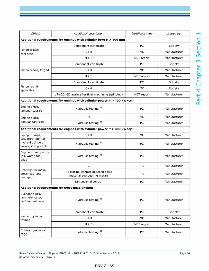
Part
4 C
hapt
er 3
Sec
tion
1
Rules for classification: Ships — DNVGL-RU-SHIP Pt.4 Ch.3. Edition January 2017 Page 34Rotating machinery - drivers
DNV GL AS
Object Additional description Certificate type Issued by
Additional requirements for engines with cylinder bore D > 400 mm
Component certificate PC Society
C+M MC ManufacturerPiston crown,cast steel
UT+CD NDT report Manufacturer
Component certificate PC Society
C+M MC ManufacturerPiston crown, forged
UT+CD NDT report Manufacturer
Component certificate PC Society
C+M MC SocietyPiston rod, ifapplicable
UT+CD, CD again after final machining (grinding) NDT report Manufacturer
Additional requirements for engines with cylinder power P > 400 kW/cyl
Engine block,lamellar cast iron
Hydraulic testing 2) PC Manufacturer
M MC ManufacturerEngine block,nodular cast iron Hydraulic testing 2) PC Manufacturer
Additional requirements for engines with cylinder power P > 800 kW/cyl
C+M MC ManufacturerPiping, pumps,actuators, etc. forhydraulic drive ofvalves, if applicable
Hydraulic testing 2) PC Manufacturer
Engine driven pumps(oil, water, fuel,bilge)
Hydraulic testing 2) PC Manufacturer
C TR Manufacturer
UT (for full contact between basicmaterial and bearing metal) TR Manufacturer
Bearings for main,crosshead, andcrankpin
Dimensional control PC Manufacturer
Additional requirements for cross head engines:
Cylinder block,lammelar cast-/nodular cast iron
Hydraulic testing 2) PC Manufacturer
Component certificate PC Society
C+M MC ManufacturerWelded cylinderframes
UT+CD NDT report Manufacturer
Exhaust gas valvecage Hydraulic testing 2) PC Manufacturer

Part
4 C
hapt
er 3
Sec
tion
1
Rules for classification: Ships — DNVGL-RU-SHIP Pt.4 Ch.3. Edition January 2017 Page 35Rotating machinery - drivers
DNV GL AS
Object Additional description Certificate type Issued by
Component certificate PC Society
C+M MC SocietyCross headUT+CD, CD again after final
machining (grinding and polishing) NDT report Manufacturer
Component certificate PC Society
C+M MC Manufacturer
UT+CD NDT report ManufacturerTie rod
Thread making TR Manufacturer
Certification standard is the DNV GL rules.
PC or MC issued by the Society (based on the DNV GL rules) = VL certificate (see Pt.1 Ch.3 Sec.5).
PC or MC issued by the manufacturer (based on the DNV GL rules) = works certificate (see Pt.1 Ch.3 Sec.5).
M+C = Material properties include chemical composition and mechanical properties, and also surface treatment such assurface hardening (hardness, depth and extent), peening and rolling (extent and applied force).
NDT = Non-destructive examination means e.g. ultrasonic testing, crack detection by MPI or DP.
UT = Ultrasonic testing
CD = Crack detection
1) Charge air coolers need only be tested on the water side2) Hydraulic testing is applied on the water or oil side of the component. Items shall be tested by hydraulic pressure
at the pressure equal to 1.5 times the maximum working pressure. High pressure parts of the fuel injection systemshall be tested by hydraulic pressure at the pressure equal to 1.5 maximum working pressure or maximum workingpressure plus 300 bar, whichever is the less. Where design or testing features may require modification of these testrequirements, special consideration may be given.
3.2.7 For general certification requirements, see Pt.1 Ch.3 Sec.4.
3.2.8 For a definition of the certification types, see Pt.1 Ch.3 Sec.5.
3.3 Inspection during assembly
3.3.1 For crosshead engines the report on alignment of the bedplate, the crankshaft deflection, the guidesand pistons shall be reviewed by the surveyor. The crankshaft deflections shall be reported at the differentmanufacturing steps.
4 Workshop testing
4.1 Application
4.1.1 Engines shall be subjected to trials on the test bed at the manufacturer's works and under theSociety's supervision. The scope of these trials shall be as specified below. Exceptions to this require theagreement of the Society.
4.1.2 All relevant equipment for safety of personnel shall be operational during the workshop testing.

Part
4 C
hapt
er 3
Sec
tion
1
Rules for classification: Ships — DNVGL-RU-SHIP Pt.4 Ch.3. Edition January 2017 Page 36Rotating machinery - drivers
DNV GL AS
4.1.3 Scope of works trialsDuring the trials the operating values corresponding to each load point shall be measured and recordedby the engine manufacturer. All the results shall be compiled in a test report to be issued by the enginemanufacturer.In each case all measurements conducted at the various load points shall be carried out under steadyoperating conditions.The readings for 100% power (rated power at rated speed) shall be taken twice at an interval of at least 30minutes
4.1.4 After running on the test bed, the fuel delivery system of main engines shall be so adjusted that afterinstallation on board overload power cannot be delivered. The limitation of the fuel delivery system shall besecured permanently.
4.1.5 Subject to the prescribed conditions, engines driving electrical generators shall be capable of overloadoperation (110% rated power) in order to utilize 100% of rated load in parallel operation.
4.1.6 Workshop testing of engines less than 100 kWFor engines with rated power less than 100 kW, scope of workshop tests is identical with that of type testing,see [2.14.2].
4.2 General engine tests4.2.1 Ambient conditionThe following external shall be recorded:
— ambient air temperature— ambient air pressure— atmospheric humidity— external cooling water temperature.
4.2.2 Engine performanceEngine data shall be measured and recorded according to the specification of the engine manufacturer andapproved by the Society.
Guidance note:The operating time per load point depends on the engine size (achievement of steady state condition) and on the time forcollection of the operating values. An operating time of 0.5 to 1 hour should be assumed per load point.
---e-n-d---o-f---g-u-i-d-a-n-c-e---n-o-t-e---
4.2.3 Integration testFor electronically controlled engines integration test shall be conducted to demonstrate that the response ofthe complete mechanical, hydraulic and electronic system is as predicted for all intended operational modes.The scope of these tests shall be proposed by the manufacturer/licensor based on the FMEA required in Table2 and Table 3 and agreed by the Society.
4.2.4 Demonstration of fire protection measuresThe following fire protection measures shall be demonstrated:
— jacketing of high-pressure fuel oil lines, including system for detection of leakage, see [2.8.6]— screening of pipe connections in piping containing flammable liquids, see [2.6.2]— insulation of hot surfaces, see [2.6.1].
Insulation of hot surfaces shall be verified while running the engine at rated power, alternatively at theoverload approved for intermittent use. The temperature measurements shall be done with contactthermometer or infrared thermometers.
Part
4 C
hapt
er 3
Sec
tion
1
Rules for classification: Ships — DNVGL-RU-SHIP Pt.4 Ch.3. Edition January 2017 Page 37Rotating machinery - drivers
DNV GL AS
Hotspots (areas with temperature ≥ 200 °C) detected during the type approval test shall be the main areasfor temperature measurement.If there have been made revisions to the insulation, additional measurements at these areas is required.
Guidance note:Additional measurements required due to change of insulation, may require the use of thermal camera to identify possiblehotspots.
---e-n-d---o-f---g-u-i-d-a-n-c-e---n-o-t-e---
4.3 Testing of propulsion engines4.3.1 Propulsion engines for direct propeller driveThe load tests shall be performed according to a) - c), functional tests according to d) - h).
a) 100% power (rated power)at 100% engine speed (rated engine speed)for at least 60 minutes after reaching the steady state condition
b) 110% powerat 103% rated engine speedfor at least 15 minutes after reaching the steady-state conditionAfter the test bed trials the output shall be limited to the maximum continuous power (100% power) sothat the engine cannot be overloaded in service.
c) At approved intermittent overload (if applicable)for at least 15 minutes after reaching the steady-state condition
d) 90%, 75%, 50% and 25% power depending on application as follows:The propeller curve based on the propeller lawThis applies if the engine is driving a fixed pitch propeller, water jet or controllable pitch propeller withvariable r/min and pitch limited to nominal value.Or:The modified propeller curveThis applies if the engine is driving a controllable pitch propeller that:
— is intended to use a higher pitch than the nominal when running at reduced r/min. In this case, theload point with lowest r/min at 100% of maximum continuous rated torque shall be added
— has a combinator pitch control using reduced pitch at lower speeds. In this case the pitch limitationshave to be stated on a signboard for the purpose of manual operation.
Or:At constant speedThis applies if the engine is driving a controllable pitch propeller with constant speed or a generator forpropulsion.
e) test of starting and reversing manoeuvres
f) test of governor and independent overspeed protection device
g) test of engine shutdown devices
h) test of oil mist detection or alternative system, if available
i) test of mechanical starting interlocking device.Guidance note:The 90% power given in c), may be replaced by the project specific normal continues rating (NCR).
---e-n-d---o-f---g-u-i-d-a-n-c-e---n-o-t-e---

Part
4 C
hapt
er 3
Sec
tion
1
Rules for classification: Ships — DNVGL-RU-SHIP Pt.4 Ch.3. Edition January 2017 Page 38Rotating machinery - drivers
DNV GL AS
4.3.2 Main engines for electrical propeller driveThe load tests shall be performed according to a) - c), functional tests according to d) - h)
a) 100% power (rated power):for at least 60 minutes after reaching the steady state condition
b) 110% power:for at least 15 minutes after reaching the steady-state conditionAfter the test bed trials the output of engines driving generators shall be so adjusted that overload(110%) power can be supplied in service after installation on board in such a way that the governingcharacteristics and the requirements of the generator protection devices can be fulfilled at all times.
c) At approved intermittent overload (if applicable)for at least 15 minutes after reaching the steady-state condition
d) 75%, 50% and 25% power and idle rune) start-up testsf) test of governor and independent overspeed protection deviceg) test of engine shutdown devicesh) test of oil mist detection or alternative system, if availablei) test of mechanical starting interlocking device.
4.3.3 Testing of surge marginsPropulsion engines with a turbocharger which is served by cylinder groups with combined power in excessof 2 500 kW shall be tested with regard to surge margins. The below mentioned tests may be waived ifsuccessfully tested earlier on an identical configuration of engine and turbochargerFor 4-stroke engines, the following test shall be performed without indication of surging:
— at rated power, the speed shall be reduced with constant torque (fuel index) down to 90% power— with 50% power at 80% speed (propeller characteristic for fixed pitch), the speed shall be reduced to
72% while keeping constant torque (fuel index).
For 2-stroke engines, the surge margin shall be demonstrated by at least one of the following methods:
1) Engine working line established at the workshop testing of engine (w/turbocharger) shall be plotted intothe compressor map of the turbocharger. There shall be at least 15% surge margin in the full load range,i.e. working flow shall be 15% above the theoretical flow at surge limit (at constant pressure).
2) Sufficient surge margin shall be demonstrated by sudden fuel cut-off to at least one cylinder. Forapplications with more than one turbocharger, cut the fuel supply to the cylinder closest upstream toeach turbocharger.This test shall be performed at two different engine loads:
— the maximum power permitted for one cylinder misfiring— the engine load corresponding to a charge air pressure of about 0.6 bar (but without auxiliary blowers
running).
3) Sufficient surge margin shall be demonstrated by an abrupt (< 2 sec) reduction in power from MCR to50% of MCR.Acceptance criteria for alternative 2) and 3):
— no continuous surging is accepted, and the turbocharger shall stabilise itself at the new load within 20seconds.
4.4 Testing of auxiliary driving engines and engines driving electricalgenerators
4.4.1 The scope of tests shall be performed according to [4.3.2].
Part
4 C
hapt
er 3
Sec
tion
1
Rules for classification: Ships — DNVGL-RU-SHIP Pt.4 Ch.3. Edition January 2017 Page 39Rotating machinery - drivers
DNV GL AS
4.4.2 In case of engines driving electrical generators the rated electrical power as specified by themanufacturer shall be verified as minimum power.
4.5 Survey after testing
4.5.1 All inspection covers shall be opened and the condition after trial shall be surveyed by the Societyrepresentative.
4.5.2 The crankshaft deflections shall be measured and checked according to the manufacturer’sspecification. The condition of the crankshaft at the time of deflection measurements (hot or cold) shall benoted on the record.
4.5.3 Component inspectionThe extend of random checks of components to be presented for inspection after the work shop test, shall beagreed with the Society representative.
Guidance note:Typical components for inspection after the engine's work shop test:
— camshaft drive train
— cams and cam rollers
— one piston to be removed for inspection of the unit.
— one crosshead with bearing and guide, if applicable
— one crankpin bearing
— one cylinder head with valves disassembled
— one main bearing.
If deemed necessary by the surveyor, further dismantling of the engine may be required.
---e-n-d---o-f---g-u-i-d-a-n-c-e---n-o-t-e---
5 Control and monitoring
5.1 General
5.1.1 The requirements in this sub-section are in addition to those given in Ch.9. For requirements related todesign of the control and monitoring system in terms of:
— automatic control— remote control— safety system— when, where and how to present alarms— what kind of indication to be presented where— system operation and maintenance— power distribution
see Ch.9 Sec.3.In case of engines intended for vessels approved for unmanned machinery installations (class notation E0),Pt.6 Ch.2 Sec.2 and in case of gas fuelled ship installations, Pt.6 Ch.2 Sec.5 applies in addition to theserequirements.
5.1.2 Electronic components and systemsElectronic components and systems shall be documented according to Table 4 and certified according to Table8.

Part
4 C
hapt
er 3
Sec
tion
1
Rules for classification: Ships — DNVGL-RU-SHIP Pt.4 Ch.3. Edition January 2017 Page 40Rotating machinery - drivers
DNV GL AS
5.1.3 In the case of engine installations up to a total output of 600 kW, simplifications can be agreed withthe Society.
Guidance note:Control and monitoring according to Table 11, is acceptable, but shut down due to low lube oil pressure according to Table 9 to beprovided.
---e-n-d---o-f---g-u-i-d-a-n-c-e---n-o-t-e---
5.2 Speed governing5.2.1 Main and auxiliary enginesEach engine not used to drive an electrical generator shall be equipped with a speed governor or regulatoradjusted such that the engine speed cannot exceed the rated speed by more than 15%.
5.2.2 Engines driving electrical generatorsFor engine requirements to load response and speed variations in steady state and in transient operations,see Ch.2 Sec.5 [1.1].
5.2.3 Use of electrical/electronic governors
5.2.3.1 The governor and the associated actuator shall, for controlling the respective engine, be suitablefor the operating conditions laid down in the rules and for the requirements specified by the enginemanufacturer.The regulating conditions required for each individual application as described in [5.2.1] and [5.2.2] shall besatisfied by the governor system.For requirements to power supply arrangement, see Ch.9.Speed sensor cabling shall be mechanically well protected.Alarms to warn of faults in the governor system shall be arranged.Governors for engines, other than those driving electrical generators, which keep the last position uponpower failure, are regarded as fulfilling the redundancy type R0. Power supply to have redundancy type R0.
5.2.3.2 Requirements applying to main enginesFor single engine plants it has to be ensured that in case of a failure of the electrical/electronic governoror electronic engine management system the control of the engine can be taken over by another controldevice, within the time required by redundancy type described in Ch.1 Sec.3. Electronic governors shall havetheir power supply independent of other consumers and the governor including its power supplies shall bearranged with redundancy type R0.To ensure continuous speed control or immediate resumption of control after a fault at least one of thefollowing requirements shall be satisfied:
a) the governor system has an independent back-up system orb) there is a redundant governor assembly for manual change-over with a separately protected power
supply orc) the engine has a manually operated fuel admission control system suitable for manoeuvring.
5.2.3.3 Requirements applying to auxiliary engines driving electrical generatorsEach auxiliary engine shall be equipped with its own governor system.In the event of a fault of components or functions which are essential for the speed control in the governorsystem, the speed demand output shall be set to “0” (i.e. the fuel admission in the injection pump shall beset to “0”). Alarms to warn of faults in the governor system shall be arranged.
Part
4 C
hapt
er 3
Sec
tion
1
Rules for classification: Ships — DNVGL-RU-SHIP Pt.4 Ch.3. Edition January 2017 Page 41Rotating machinery - drivers
DNV GL AS
5.3 Overspeed protection
5.3.1 In addition to the normal governor, each engine with a rated power of 220 kW or over shall be fittedwith an independent overspeed protection device so adjusted that the engine speed cannot exceed the ratedspeed by more than 20% except for diesel engines driving generators where protection device shall preventthe engine speed from exceeding the rated speed by more than 15%.
Guidance note:An independent overspeed protection device means a system all of whose component parts, including the drive, functionindependently of the normal governor.
---e-n-d---o-f---g-u-i-d-a-n-c-e---n-o-t-e---
5.3.2 For engines operating in areas defined as gas hazardous zones or spaces (see applicable classnotation), an additional device that automatically shuts the air inlet in case of overspeed is required. Thisdevice shall activate at the same speed level as the overspeed protective device required in [5.3.1]. Forengines with turbochargers that can suffer overspeed due to a sudden shut of air intake, the shutting deviceshall be between the turbocharger and the engine.
5.4 Propulsion engines
5.4.1 The propulsion engines shall as a minimum be fitted with instrumentation and alarms according toTable 9 if not otherwise approved.
5.4.2 Local control stationFor local operation without remote control of the propulsion plant a local control station shall be installedfrom which the plant can be operated and monitored.
5.4.3 Indicators according to Table 9 shall be clearly visible at the local main engine control station.
5.4.4 Temperature indicators shall be provided at the local control station or directly on the engine.
5.4.5 Barred speed ranges shall be marked in red on the tachometers.
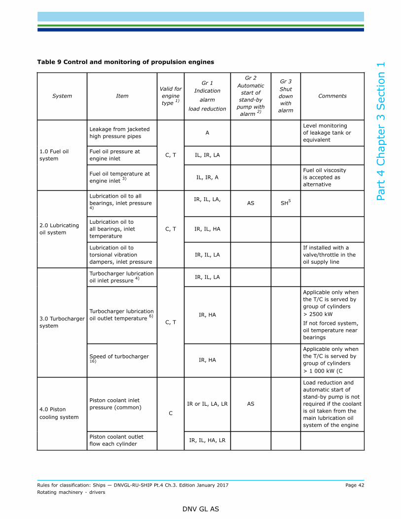
Part
4 C
hapt
er 3
Sec
tion
1
Rules for classification: Ships — DNVGL-RU-SHIP Pt.4 Ch.3. Edition January 2017 Page 42Rotating machinery - drivers
DNV GL AS
Table 9 Control and monitoring of propulsion engines
System ItemValid forenginetype 1)
Gr 1Indication
alarm
load reduction
Gr 2Automatic
start ofstand-by
pump withalarm 2)
Gr 3Shutdownwith
alarm
Comments
Leakage from jacketedhigh pressure pipes A
Level monitoringof leakage tank orequivalent
Fuel oil pressure atengine inlet IL, IR, LA1.0 Fuel oil
system
Fuel oil temperature atengine inlet 3)
C, T
IL, IR, AFuel oil viscosityis accepted asalternative
Lubrication oil to allbearings, inlet pressure4)
IR, IL, LA,
AS SH5
Lubrication oil toall bearings, inlettemperature
IR, IL, HA2.0 Lubricatingoil system
Lubrication oil totorsional vibrationdampers, inlet pressure
C, T
IR, IL, LAIf installed with avalve/throttle in theoil supply line
Turbocharger lubricationoil inlet pressure 4) IR, IL, LA
Turbocharger lubricationoil outlet temperature 6) IR, HA
Applicable only whenthe T/C is served bygroup of cylinders> 2500 kW
If not forced system,oil temperature nearbearings
3.0 Turbochargersystem
Speed of turbocharger16)
C, T
IR, HA
Applicable only whenthe T/C is served bygroup of cylinders> 1 000 kW (C
Piston coolant inletpressure (common) IR or IL, LA, LR AS
Load reduction andautomatic start ofstand-by pump is notrequired if the coolantis oil taken from themain lubrication oilsystem of the engine
4.0 Pistoncooling system
Piston coolant outletflow each cylinder
C
IR, IL, HA, LR

Part
4 C
hapt
er 3
Sec
tion
1
Rules for classification: Ships — DNVGL-RU-SHIP Pt.4 Ch.3. Edition January 2017 Page 43Rotating machinery - drivers
DNV GL AS
System ItemValid forenginetype 1)
Gr 1Indication
alarm
load reduction
Gr 2Automatic
start ofstand-by
pump withalarm 2)
Gr 3Shutdownwith
alarm
Comments
Cylinder cooling inletpressure or flow IR, IL, LA AS
Monitoring ofexpansion tanklevel, with alarmat low level, is anacceptable alternativefor engines withcylinder power< 130 kW
5.0 Cylindercooling medium
Cylinder cooling watertemperature at engineoutlet
C, T
IR, IL, HA
Temperature to bemonitored for eachcylinder if individualstop valves are fittedfor the cylinderjackets, otherwisemain outlet.
Sensor location soas to enable alarm inevent of closed valve
Control air pressure (ifarranged) C, T IR or IL, LA6.0 Starting
and control airsystems Starting air pressure C, T IR or IL, LA
6.1 Pneumaticreturn ofexhaust valve
Exhaust gas valve airspring pressure C IR or IL, LA
Pressure readingsshall be taken at thesupply line locally onthe engine
Charge air pressure C, T IR or IL
Charge air temperature,under each piston (firedetection)
C LR7.0 Charge airsystem
Charge air temperatureat charge air cooleroutlet
C, T IR or IL, HA
Exhaust gas temp aftereach cylinder 7)
HAIR, LR 8)
8.0 Exhaust gassystem Exhaust gas temp
before T/C 9)
C, T
IR, HA, LR
LR is only requiredwhen the T/C isserved by group ofcylinders> 2 500 kW
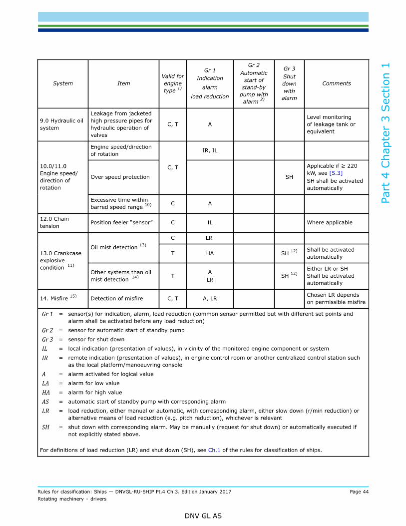
Part
4 C
hapt
er 3
Sec
tion
1
Rules for classification: Ships — DNVGL-RU-SHIP Pt.4 Ch.3. Edition January 2017 Page 44Rotating machinery - drivers
DNV GL AS
System ItemValid forenginetype 1)
Gr 1Indication
alarm
load reduction
Gr 2Automatic
start ofstand-by
pump withalarm 2)
Gr 3Shutdownwith
alarm
Comments
9.0 Hydraulic oilsystem
Leakage from jacketedhigh pressure pipes forhydraulic operation ofvalves
C, T ALevel monitoringof leakage tank orequivalent
Engine speed/directionof rotation IR, IL
Over speed protection
C, T
SH
Applicable if ≥ 220kW, see [5.3]SH shall be activatedautomatically
10.0/11.0Engine speed/direction ofrotation
Excessive time withinbarred speed range 10) C A
12.0 Chaintension Position feeler “sensor” C IL Where applicable
C LR
Oil mist detection 13)
T HA SH 12) Shall be activatedautomatically13.0 Crankcase
explosivecondition 11)
Other systems than oilmist detection 14) T
ALR
SH 12)Either LR or SHShall be activatedautomatically
14. Misfire 15) Detection of misfire C, T A, LR Chosen LR dependson permissible misfire
Gr 1 = sensor(s) for indication, alarm, load reduction (common sensor permitted but with different set points andalarm shall be activated before any load reduction)
Gr 2 = sensor for automatic start of standby pump
Gr 3 = sensor for shut down
IL = local indication (presentation of values), in vicinity of the monitored engine component or system
IR = remote indication (presentation of values), in engine control room or another centralized control station suchas the local platform/manoeuvring console
A = alarm activated for logical value
LA = alarm for low value
HA = alarm for high value
AS = automatic start of standby pump with corresponding alarm
LR = load reduction, either manual or automatic, with corresponding alarm, either slow down (r/min reduction) oralternative means of load reduction (e.g. pitch reduction), whichever is relevant
SH = shut down with corresponding alarm. May be manually (request for shut down) or automatically executed ifnot explicitly stated above.
For definitions of load reduction (LR) and shut down (SH), see Ch.1 of the rules for classification of ships.

Part
4 C
hapt
er 3
Sec
tion
1
Rules for classification: Ships — DNVGL-RU-SHIP Pt.4 Ch.3. Edition January 2017 Page 45Rotating machinery - drivers
DNV GL AS
System ItemValid forenginetype 1)
Gr 1Indication
alarm
load reduction
Gr 2Automatic
start ofstand-by
pump withalarm 2)
Gr 3Shutdownwith
alarm
Comments
1) C = crosshead engine, T = trunk engine.2) To be provided when stand-by pump is required, see Ch.1.3) For engines running on heavy fuel oil only.4) Pressure to be monitored for all inlets to main bearings, crosshead bearings, camshaft bearings and turbocharger
where pressure may differ due to presence of pumps, throttles, rotor seals or pressure reduction valves.5) Only for engine output ≥ 220 kW.6) Where outlet temperature from each bearing cannot be monitored due to the engine/turbocharger design alternative
arrangements may be accepted. Continuous monitoring of inlet pressure and inlet temperature in combination withspecific intervals for bearing inspection in accordance with the turbocharger manufacturer’s instructions may beaccepted as an alternative.
7) Applicable when cylinder power > 500 kW.8) Alarm with request for load reduction to be given in case of excessive average exhaust gas temperature. This
applies when there is no separate sensor before T/C, and the T/C is served by a group of cylinders > 1 000 kW. Thealarm level shall be set with due considerations to safe operation of T/C.
9) Applicable only when the T/C is served by a group of cylinders > 1 000 kW and if no individual exhaust gastemperature for each cylinder.
10) When driving in barred speed range in excess of approved maximum duration set by torsional vibration level in theshafting (where deemed necessary, limitations in duration shall be given in connection approval of torsional vibrationanalysis). This safety device shall only be required when so stated in connection with approval of torsional vibrationanalysis.
11) Applicable to engines of 2 250 kW and above, or with cylinder diameter > 300 mm.12) One crankcase explosive condition monitoring device having two independent outputs for detecting alarm and shut-
down is acceptable.13) Oil mist detectors shall be type tested in accordance with IACS UR M67.14) Alternative methods of monitoring may be approved by the Society, see [5.7.10].15) If required by torsional vibration calculations, diesel engines with cylinder output of 130 kW and above shall have
means to detect misfire.16) On turbocharging systems where turbochargers are activated sequentially, speed monitoring is not required for the
turbocharger(s) being activated last in the sequence provided all turbochargers share the same intake air filter andthey are not fitted with waste gates.
5.5 Auxiliary engines
5.5.1 Engines driving generators in electric propulsion systems shall be equipped with sensors and monitoredas propulsion engines (Table 9) and with safety actions according to Table 10.

Part
4 C
hapt
er 3
Sec
tion
1
Rules for classification: Ships — DNVGL-RU-SHIP Pt.4 Ch.3. Edition January 2017 Page 46Rotating machinery - drivers
DNV GL AS
Table 10 Control and monitoring of auxiliary engines
System Item
Gr 1Indication
alarm
load reduction
Gr 2Automatic
start ofstand-by
pump withalarm 1)
Gr 3Shut
down withalarm
Comment
Leakage from jacketedhigh pressure pipes A Level monitoring of leakage
tank or equivalent
Fuel oil pressure atengine inlet IR, IL1.0 Fuel oil
system
Fuel oil temperature atengine inlet 2) IR, IL, A Fuel oil viscosity is accepted
as alternative
Lubrication oil to mainbearings, inlet pressure IR or IL, LA, AS SH 3)
2.0 Lubricatingoil system Lubrication oil to
main bearings, inlettemperature
IR or IL, HA
Turbocharger lubricationoil inlet pressure IR or IL, LA
Turbocharger lubricationoil outlet temperature 4) IR or IL, HA
Applicable only when theT/C is served by group ofcylinders
> 2500 kW
If not forced system, oiltemperature near bearings
3.0Turbochargersystem
Speed of turbocharger14) IR or IL, HA
Applicable only when theT/C is served by group ofcylinders > 1 000 kW
Cylinder cooling inletpressure or flow IR or IL, LA AS
Monitoring of expansion tanklevel, with alarm at low level,is an acceptable alternativefor engines with cylinderpower < 130 kW
4.0 Cylindercooling medium
Cylinder cooling watertemperature at engineoutlet
IR or IL, HA, LR SH Either LR or SH
Exhaust gas temp aftereach cylinder 5)
IR or IL, HA,LR 6)
SH may replace LR for electricpower generating engines
5.0 Exhaust gassystem Exhaust gas temp before
T/C 7) IR or IL, HA, LR
The LR is only required whenthe T/C is served by group ofcylinders > 2 500 kWSH may replace LR for electricpower generating engines

Part
4 C
hapt
er 3
Sec
tion
1
Rules for classification: Ships — DNVGL-RU-SHIP Pt.4 Ch.3. Edition January 2017 Page 47Rotating machinery - drivers
DNV GL AS
System Item
Gr 1Indication
alarm
load reduction
Gr 2Automatic
start ofstand-by
pump withalarm 1)
Gr 3Shut
down withalarm
Comment
6.0 Hydraulic oilsystem
Leakage from jacketedhigh pressure pipes forhydraulic operation ofvalves
A Level monitoring of leakagetank or equivalent
Engine speed IR, IL
For engines other than forelectric power generation,local indication is anacceptable alternative7.0/8.0 Engine
speed/directionof rotation
Overspeed protection SH
Applicable if P ≥ 220 kW, see[5.3].SH shall be activatedautomatically
Oil mist detection 10) HA SH 9) Shall be activatedautomatically9.0 Crankcase
explosivecondition 8) Other systems than oil
mist detection 11) A SH 9) Shall be activatedautomatically
14. Misfire 12) Detection of misfire A, LR SH 13)
Depending on permissiblemisfire, LR is accepted asalternative to SH for auxiliaryengines other than drivinggenerators
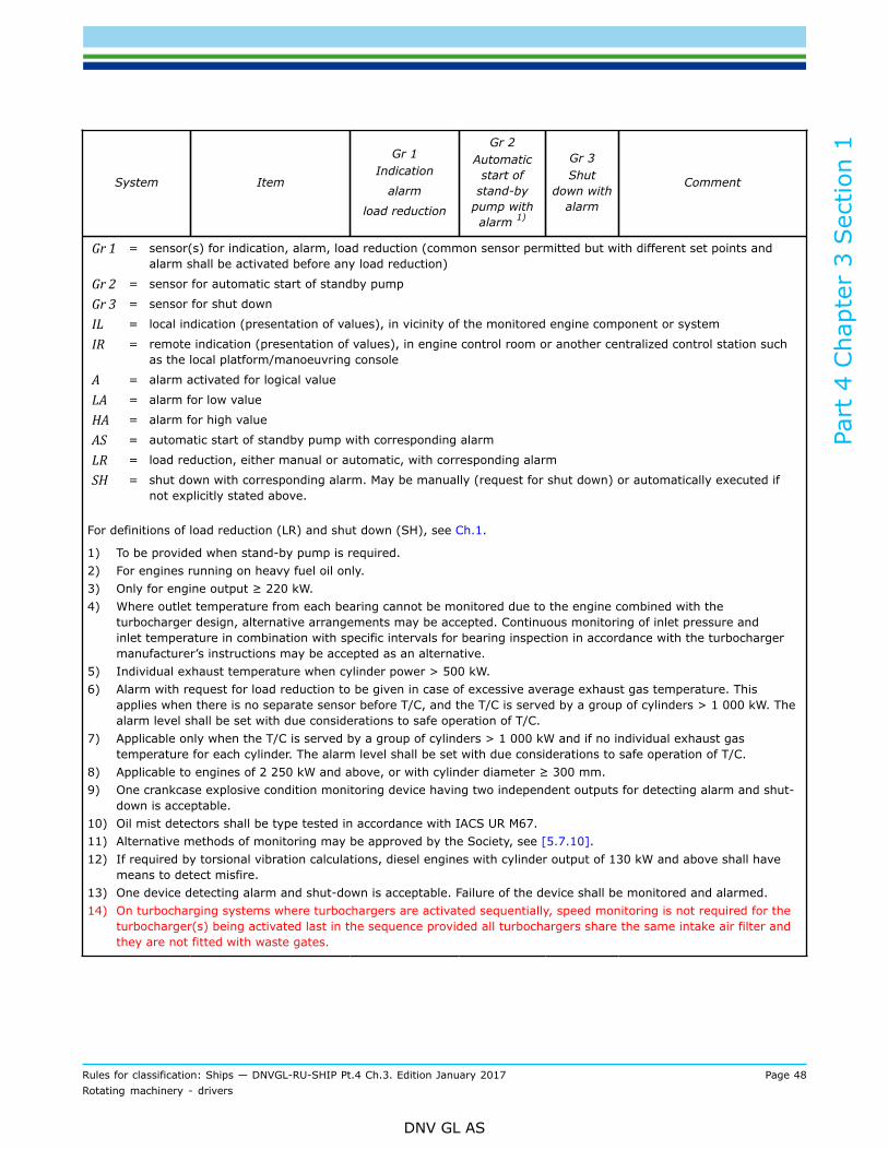
Part
4 C
hapt
er 3
Sec
tion
1
Rules for classification: Ships — DNVGL-RU-SHIP Pt.4 Ch.3. Edition January 2017 Page 48Rotating machinery - drivers
DNV GL AS
System Item
Gr 1Indication
alarm
load reduction
Gr 2Automatic
start ofstand-by
pump withalarm 1)
Gr 3Shut
down withalarm
Comment
Gr 1 = sensor(s) for indication, alarm, load reduction (common sensor permitted but with different set points andalarm shall be activated before any load reduction)
Gr 2 = sensor for automatic start of standby pump
Gr 3 = sensor for shut down
IL = local indication (presentation of values), in vicinity of the monitored engine component or system
IR = remote indication (presentation of values), in engine control room or another centralized control station suchas the local platform/manoeuvring console
A = alarm activated for logical value
LA = alarm for low value
HA = alarm for high value
AS = automatic start of standby pump with corresponding alarm
LR = load reduction, either manual or automatic, with corresponding alarm
SH = shut down with corresponding alarm. May be manually (request for shut down) or automatically executed ifnot explicitly stated above.
For definitions of load reduction (LR) and shut down (SH), see Ch.1.
1) To be provided when stand-by pump is required.2) For engines running on heavy fuel oil only.3) Only for engine output ≥ 220 kW.4) Where outlet temperature from each bearing cannot be monitored due to the engine combined with the
turbocharger design, alternative arrangements may be accepted. Continuous monitoring of inlet pressure andinlet temperature in combination with specific intervals for bearing inspection in accordance with the turbochargermanufacturer’s instructions may be accepted as an alternative.
5) Individual exhaust temperature when cylinder power > 500 kW.6) Alarm with request for load reduction to be given in case of excessive average exhaust gas temperature. This
applies when there is no separate sensor before T/C, and the T/C is served by a group of cylinders > 1 000 kW. Thealarm level shall be set with due considerations to safe operation of T/C.
7) Applicable only when the T/C is served by a group of cylinders > 1 000 kW and if no individual exhaust gastemperature for each cylinder. The alarm level shall be set with due considerations to safe operation of T/C.
8) Applicable to engines of 2 250 kW and above, or with cylinder diameter ≥ 300 mm.9) One crankcase explosive condition monitoring device having two independent outputs for detecting alarm and shut-
down is acceptable.10) Oil mist detectors shall be type tested in accordance with IACS UR M67.11) Alternative methods of monitoring may be approved by the Society, see [5.7.10].12) If required by torsional vibration calculations, diesel engines with cylinder output of 130 kW and above shall have
means to detect misfire.13) One device detecting alarm and shut-down is acceptable. Failure of the device shall be monitored and alarmed.14) On turbocharging systems where turbochargers are activated sequentially, speed monitoring is not required for the
turbocharger(s) being activated last in the sequence provided all turbochargers share the same intake air filter andthey are not fitted with waste gates.

Part
4 C
hapt
er 3
Sec
tion
1
Rules for classification: Ships — DNVGL-RU-SHIP Pt.4 Ch.3. Edition January 2017 Page 49Rotating machinery - drivers
DNV GL AS
5.6 Emergency engines
5.6.1 The requirements of [5.6] apply to engines for emergency duty.
5.6.2 Engines for emergency duty shall as a minimum be fitted with instrumentation and alarms accordingto Table 11, if not otherwise approved. No additional protective function shall result in a shutdown.
Table 11 Control and monitoring of engines for emergency duty
System Item
Gr 1Indication
alarm
loadreduction
Gr 2Automatic
start ofstand-by
pump withalarm 1)
Gr 3Shut downwith alarm
Comment
1.0 Fuel oilsystem
Leakage from jacketedhigh pressure pipes A Level monitoring of leakage tank or
equivalent
Lubrication oil tomain bearings, inletpressure
IL, LA
2.0 Lubricatingoil system Lubrication oil
temperature at engineinlet
IL, HA HA applicable if P ≥ 220 kW
Cylinder cooling watertemperature at engineoutlet
IL, HA4.0 Cylindercoolingmedium Cylinder cooling water
pressure/flow atengine inlet
IL, LA LA applicable if P ≥ 220 kW
Engine speed IL7.0/8.0 Enginespeed Overspeed protection SH
Applicable if P ≥ 220 kW, see [5.3]
Shall be activated automatically
Oil mist detection 3) HA9.0 Crankcaseexplosivecondition 2) Other systems than oil
mist detection 4) A
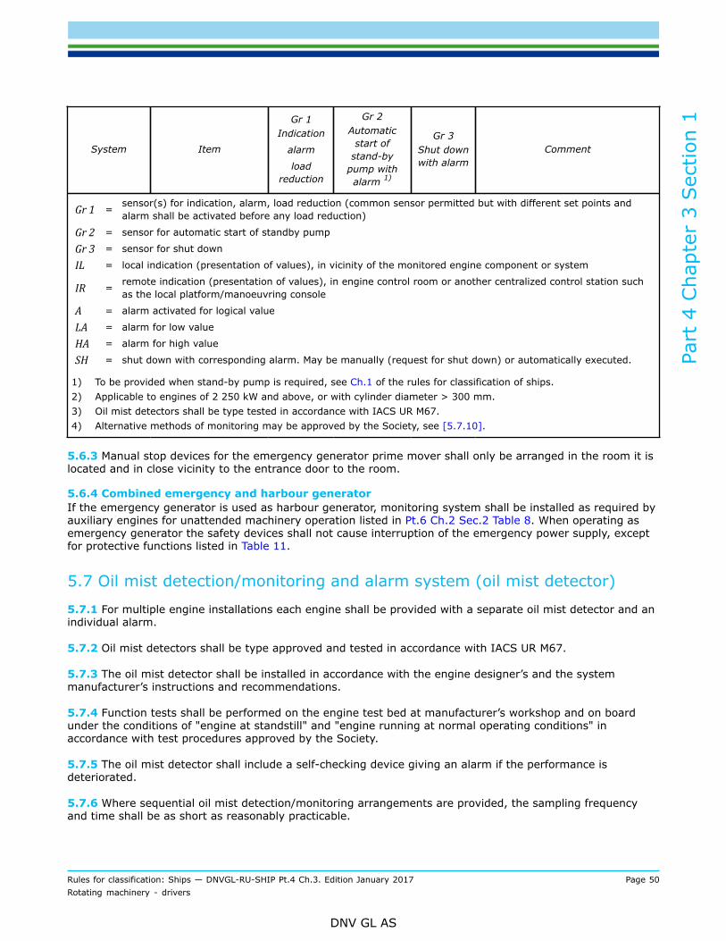
Part
4 C
hapt
er 3
Sec
tion
1
Rules for classification: Ships — DNVGL-RU-SHIP Pt.4 Ch.3. Edition January 2017 Page 50Rotating machinery - drivers
DNV GL AS
System Item
Gr 1Indication
alarm
loadreduction
Gr 2Automatic
start ofstand-by
pump withalarm 1)
Gr 3Shut downwith alarm
Comment
Gr 1 = sensor(s) for indication, alarm, load reduction (common sensor permitted but with different set points andalarm shall be activated before any load reduction)
Gr 2 = sensor for automatic start of standby pump
Gr 3 = sensor for shut down
IL = local indication (presentation of values), in vicinity of the monitored engine component or system
IR = remote indication (presentation of values), in engine control room or another centralized control station suchas the local platform/manoeuvring console
A = alarm activated for logical value
LA = alarm for low value
HA = alarm for high value
SH = shut down with corresponding alarm. May be manually (request for shut down) or automatically executed.
1) To be provided when stand-by pump is required, see Ch.1 of the rules for classification of ships.2) Applicable to engines of 2 250 kW and above, or with cylinder diameter > 300 mm.3) Oil mist detectors shall be type tested in accordance with IACS UR M67.4) Alternative methods of monitoring may be approved by the Society, see [5.7.10].
5.6.3 Manual stop devices for the emergency generator prime mover shall only be arranged in the room it islocated and in close vicinity to the entrance door to the room.
5.6.4 Combined emergency and harbour generatorIf the emergency generator is used as harbour generator, monitoring system shall be installed as required byauxiliary engines for unattended machinery operation listed in Pt.6 Ch.2 Sec.2 Table 8. When operating asemergency generator the safety devices shall not cause interruption of the emergency power supply, exceptfor protective functions listed in Table 11.
5.7 Oil mist detection/monitoring and alarm system (oil mist detector)
5.7.1 For multiple engine installations each engine shall be provided with a separate oil mist detector and anindividual alarm.
5.7.2 Oil mist detectors shall be type approved and tested in accordance with IACS UR M67.
5.7.3 The oil mist detector shall be installed in accordance with the engine designer’s and the systemmanufacturer’s instructions and recommendations.
5.7.4 Function tests shall be performed on the engine test bed at manufacturer’s workshop and on boardunder the conditions of "engine at standstill" and "engine running at normal operating conditions" inaccordance with test procedures approved by the Society.
5.7.5 The oil mist detector shall include a self-checking device giving an alarm if the performance isdeteriorated.
5.7.6 Where sequential oil mist detection/monitoring arrangements are provided, the sampling frequencyand time shall be as short as reasonably practicable.

Part
4 C
hapt
er 3
Sec
tion
1
Rules for classification: Ships — DNVGL-RU-SHIP Pt.4 Ch.3. Edition January 2017 Page 51Rotating machinery - drivers
DNV GL AS
5.7.7 Arrangements of the oil mist detector shall be submitted for approval. The following particulars shall beincluded in the documentation:
— schematic layout of engine oil mist detector showing location of engine crankcase sample points andpiping arrangement together with pipe dimensions to detector/monitor
— evidence of study to justify the selected location of sample points and sample extraction rate (ifapplicable) in consideration of the crankcase arrangements and geometry and the predicted crankcaseatmosphere where oil mist can accumulate
— maintenance and test manuals— information of type approval of the detection/monitoring system and functional tests at the particular
engine.
5.7.8 A copy of the documentation supplied with the system such as maintenance and test manuals shall beprovided on board ship.
5.7.9 The readings and the alarm information from the oil mist detector shall be capable of being read froma safe location away from the engine.
5.7.10 Alternative methodsWhere alternative methods are provided to prevent the build-up of a potentially explosive condition withinthe crankcase (independent of the reason, e.g. oil mist, gas, hot spots, etc.), details shall be submitted forthe consideration of the Society. The following information shall be included in the details and submitted forapproval:
— engine particulars - type, power, speed, stroke, bore and crankcase volume— details of arrangements preventing the build-up of potentially explosive conditions within the crankcase,
e.g. bearing temperature monitoring, oil splash temperature, crankcase pressure monitoring, re-circulation arrangements, crankcase atmosphere monitoring
— evidence that the arrangements are effective in preventing the build-up of potentially explosive conditionstogether with test details or details of in service experience
— operating instructions and maintenance and test instructions.
5.7.11 Active safety measuresWhere it is proposed to use alternative active technologies to minimize the risk for a potential crankcaseexplosion, details of the arrangement and the function description shall be submitted for approval.
6 Arrangement
6.1 Engine alignment/seating
6.1.1 Engines shall be mounted and secured to their shipboard foundations in conformity with Ch.2 Sec.1[6].
6.1.2 Epoxy resin shall be type approved by the Society.
6.2 Accessibility of engines
6.2.1 Engines shall be so arranged in the engine room that all the assembly holes and inspection portsprovided by the engine manufacturer for inspections and maintenance are accessible. A change ofcomponents, as far as practicable on board, shall be possible.

Part
4 C
hapt
er 3
Sec
tion
1
Rules for classification: Ships — DNVGL-RU-SHIP Pt.4 Ch.3. Edition January 2017 Page 52Rotating machinery - drivers
DNV GL AS
Guidance note:Requirements related to space and construction has to be considered for the installation of the engines.
---e-n-d---o-f---g-u-i-d-a-n-c-e---n-o-t-e---
6.3 Earthing
6.3.1 For main engines it is necessary to ensure that the limits specified by the engine manufacturers for thedifference in electrical potential (voltage) between the crankshaft/shafting and the hull are not exceeded inservice. Appropriate earthing devices including limit value monitoring of the permitted voltage potential shallbe provided.
6.4 Starting with compressed air
6.4.1 Reference is given to Ch.6 Sec.5 [9.3].
6.5 Electrical starting equipment
6.5.1 Reference is given to Ch.8.
6.6 Exhaust pipes
6.6.1 Where exhaust pipes are led overboard near the water line, means shall be provided to avoid thepossibility of water entering the engine.
6.6.2 Exhaust pipes from several engines shall not be connected, but have separate outlets, unlessprecautions are taken to prevent the return of exhaust gases to a stopped engine.
6.6.3 All hot surfaces shall be properly insulated. There shall be no surface temperature in excess of 220°C,see [4.2.4].
6.6.4 Exhaust gas back pressureThe back pressure of the exhaust system shall not exceed the maximum allowable limit as specified bythe engine designer. In case several exhaust pipes are joined into one common pipe, the maximum backpressure shall not be exceeded with all combined engines operating at rated power, unless it can bedocumented that such a situation is not likely to occur under normal operational conditions.The exhaust system is defined to include any component and piping installed downstream of the engine exit.
6.7 Lubrication and fuel oil systems
6.7.1 The combination of the oil drainage lines from the crankcases of two or more engines is not allowed.
6.7.2 Drip trays under filters for fuel, lubrication and hydraulic oils shall be provided.
6.7.3 Pipe connections in piping containing flammable liquids shall be adequately screened. The screeningshall ensure that leakage from pipe connections does not reach potentially hot surfaces. Any insulatedsurface, where the temperature may exceed 220°C in the event that insulation is detached or otherwise isdegraded, shall be regarded a potentially hot surface, see [2.6].

Part
4 C
hapt
er 3
Sec
tion
1
Rules for classification: Ships — DNVGL-RU-SHIP Pt.4 Ch.3. Edition January 2017 Page 53Rotating machinery - drivers
DNV GL AS
6.8 Crankcase ventilation pipesThe vent pipes and oil drain pipes of two or more engines shall not be combined. Exemptions may beapproved if an interaction of the combined systems is inhibited by suitable means.
Guidance note:Oil vapour from the ventilation pipes should preferably be led to free air.
---e-n-d---o-f---g-u-i-d-a-n-c-e---n-o-t-e---
7 Vibration
7.1 Torsional and axial vibration
7.1.1 The requirements in Ch.2 Sec.2 and Ch.2 Sec.3 apply.Acceptance criteria to be decided based on crankshaft calculation in [2.5].
8 Installation inspections
8.1 Engine seatingEngines shall be mounted and secured to their shipboard foundations in conformity with Ch.2 Sec.1 [6].
8.1.1 Installation is subject to survey in accordance with Ch.2.
8.2 Engine alignmentThe crankshaft alignment shall be checked every time an engine has been aligned on its foundation bymeasurement of the crank web deflection and/or other suitable means.For the purpose of subsequent alignments, notes shall be taken of:
— the draught/load condition of the vessel— the condition of the engine - cold/preheated/hot.
9 Shipboard testing
9.1 Shipboard testing (dock and sea trials)
9.1.1 After the conclusion of the running-in programme prescribed by the engine manufacturer engines shallundergo the trials specified below.
9.1.2 Unless otherwise stated, a surveyor shall attend the tests and inspections given in [9].
9.1.3 The scope of the shipboard trials may be extended in consideration of special operating conditions suchas towing, trawling, etc.
9.2 General engine tests
9.2.1 The suitability of main and auxiliary engines to burn residual oils or other special fuels shall bedemonstrated if the machinery installation is designed to burn such fuels.
Part
4 C
hapt
er 3
Sec
tion
1
Rules for classification: Ships — DNVGL-RU-SHIP Pt.4 Ch.3. Edition January 2017 Page 54Rotating machinery - drivers
DNV GL AS
9.2.2 Starting tests shall be made in order to document the required starting air energy capacity.
9.2.3 The control, alarm and safety functions shall be tested, see Table 9, Table 10 and Table 11. Itemstested and documented in the engine workshop test, need not be retested.
9.2.4 Hot surfaces with new, damaged or changed insulation, shall be measured to identify the maximumsurface temperature, see [2.6.1]. This shall be done with contact thermometer or infrared thermometers.The measurements shall be done while the engine is running at maximum load as defined in [9.3].
Guidance note:Measurements required due to change of insulation, may require the use of thermal camera to identify possible hotspots.
---e-n-d---o-f---g-u-i-d-a-n-c-e---n-o-t-e---
9.3 Testing of engines for propulsion and main power supply9.3.1 Propulsion engines driving fixed pitch propellersThe tests shall be carried out as follows:
a) at rated engine speedfor at least 4 hoursand
b) at 103% rated engine speed:for 30 minutes where the engine adjustment permits, see [4.1.4]
c) at approved intermittent overload (if applicable)for duration as approved
d) determination of the minimum speed (loaded condition)e) starting and reversing manoeuvres, see [6.4]f) in reverse direction of propeller rotation at a minimum speed of 70% rated engine speed:
10 minutesg) testing of the monitoring and safety systemsh) correct start and stop of auxiliary blowersi) check of barred speed range, see Ch.2 Sec.2 [3].
9.3.2 Propulsion engines driving controllable pitch propellersThe requirements in [9.3.1] apply.Controllable pitch propellers shall be tested with various propeller pitches. Where provision is made foroperating in a combinator mode, the combinator curves shall be plotted and verified by measurements.
9.3.3 Propulsion engines also driving power take off (PTO) generatorThe requirements in [9.3.1] apply.If applicable, [9.3.2] apply.100% PTO power at engine rated speed, for at least 1 hour.
Part
4 C
hapt
er 3
Sec
tion
1
Rules for classification: Ships — DNVGL-RU-SHIP Pt.4 Ch.3. Edition January 2017 Page 55Rotating machinery - drivers
DNV GL AS
9.3.4 Engines driving generators for electrical propulsion and/or main power supply oremergency power supplyThe tests shall be carried out as follows:
a) 100% power (rated electrical power of generator)for at least 1 hour
b) 110% power ( rated electrical power of generator)for at least 10 minutes
c) demonstrate the engines load response, see Ch.2 Sec.5 [1]d) starting manoeuvres, for pneumatic system see Ch.6 Sec.5 [9.3], for electric starting equipment see
Ch.8 Sec.2 [5]e) testing of the monitoring and safety systems.
Guidance note:The electrical propulsion line shall be tested at 100% propulsion power for at least 4 hours.
---e-n-d---o-f---g-u-i-d-a-n-c-e---n-o-t-e---
9.4 Testing of engines driving auxiliaries
9.4.1 The tests shall be carried out as follows:
a) at 100% rated power and speedfor at least 30 min
b) at approved intermittent overload (if applicable)for duration as approved.
9.5 Engine vibration
9.5.1 For resiliently mounted engines, the engine movements shall be observed during the misfiring tests ofthe engine at as high load as possible. The engine shall not reach contact with the stoppers, see Ch.2 Sec.1[6]. None of the engine connections such as exhaust pipe compensators, cooling water bellows, lubrication oilpipes, etc. shall restrict the engine movements.
9.6 Opening up after testing
9.6.1 For engines supplied and installed in assembled condition, there are no requirements for opening upafter testing unless there is any reason to suspect any abnormal wear of, or damage to, engine components.
9.6.2 Unless otherwise approved, inspection according to [4.5] apply for propulsion engines supplied insections and assembled onboard.
10 Gas only and dual fuel engines
10.1 General
10.1.1 The rules in this section apply to gas only engines or dual fuel engines installed in ships.The rules are applicable for engines where natural gas in gaseous state is used as fuel. If other gases areused as fuel special considerations shall have to be made, and additional requirements may be relevant.

Part
4 C
hapt
er 3
Sec
tion
1
Rules for classification: Ships — DNVGL-RU-SHIP Pt.4 Ch.3. Edition January 2017 Page 56Rotating machinery - drivers
DNV GL AS
10.1.2 DefinitionsDefinitions addressing gas as fuel as given in Pt.6 Ch.2 Sec.5.
gas admission valve = valve or injector on the engine which controls the gas supply to the engineaccording to the engine’s actual gas demand
safety concept = the safety concept is a document describing the safety philosophy with regard to gasas fuel. It describes how risks associated with this type of fuel are controlled undernormal operating conditions as well as possible failure scenarios and their controlmeasures.
10.2 Design10.2.1 General functional requirementsIn case of a normal stop or an emergency shutdown, the gas fuel supply shall be shut off not later than theignition source. It shall not be possible to shut off the ignition source without first or simultaneously closingthe gas supply to each cylinder or to the complete engine. Shut off of the gas fuel shall not be dependent onthe shut off of the ignition source.
Guidance note:Firing of the gas-air mixture is not explicitly limited to the use of pilot fuel. Other ignition methods may be accepted if suitable.
---e-n-d---o-f---g-u-i-d-a-n-c-e---n-o-t-e---
10.2.2 System configurationGas fuelled engines shall either be designed to be installed in a gas safe machinery space or an ESDprotected machinery space as defined in Pt.6 Ch.2 Sec.5 [3.2.2].For installations in gas safe machinery spaces, the connection of gas piping and ducting to the gas admissionvalves shall provide complete coverage of the double ducting and make replacement and/or overhaul ofgas admission valves and cylinder covers possible. The double ducting is also required for gas pipes on theengine itself, and all the way until gas is supplied into the chamber.
Guidance note:If gas is supplied into the air inlet directly on each individual cylinder during air intake to the cylinder on a low pressure engine,such that a single failure will not lead to release of fuel gas into the machinery space, double ducting may be omitted on the airinlet manifold.
---e-n-d---o-f---g-u-i-d-a-n-c-e---n-o-t-e---
10.2.3 Functional requirements, gas-only engines
10.2.3.1 The starting sequence shall be such that fuel gas is not admitted to the cylinders until ignition isactivated and the engine has reached a minimum rotational speed.
10.2.3.2 If combustion has not been detected by the engine monitoring system within 10 s after opening ofthe gas injection valve the gas supply shall be automatically shut off and the starting sequence terminated.
Guidance note:More than 10 seconds may be accepted between gas injection start and automatic starting sequence shut off, if the gas is notinjected directly to each cylinder or to each cylinder air inlet, but is mixed with combustion air in a common system. However,safety concept and FMEA should show acceptable level of risk.
---e-n-d---o-f---g-u-i-d-a-n-c-e---n-o-t-e---
10.2.3.3 When restarting after a failed start attempt admission of fuel gas to the cylinders shall not bepossible before the exhaust gas system has been purged with an air volume of at least 3 times the volume ofthe exhaust gas system before the turbocharger(s).

Part
4 C
hapt
er 3
Sec
tion
1
Rules for classification: Ships — DNVGL-RU-SHIP Pt.4 Ch.3. Edition January 2017 Page 57Rotating machinery - drivers
DNV GL AS
Guidance note:Purging may be carried out by for example running the engine on starting air for a predetermined number of revolutions.
---e-n-d---o-f---g-u-i-d-a-n-c-e---n-o-t-e---
10.2.4 Functional requirements, dual fuel engines
10.2.4.1 Dual fuel engines shall start, activate normal stop and perform low power operation on oil fuel only.Gas injection shall not be possible without a corresponding pilot oil injection. In case of shut-off of the gasfuel supply, the engines shall be capable of continuous operation by oil fuel only.
Guidance note:If it can be documented that a dual fuel engine can safely start, stop and operate on low load in gas mode, this may be approved.
---e-n-d---o-f---g-u-i-d-a-n-c-e---n-o-t-e---
10.2.4.2 Changeover to and from gas fuel operation shall only be possible at a power level where it canbe done with acceptable reliability as demonstrated through testing. On completion of preparations forchangeover to gas operation including checks of all essential conditions for changeover, the changeoverprocess itself shall be automatic. Manual interruption should be possible in all cases.
10.2.4.3 Firing of the gas-air mixture in the cylinders shall be initiated by injection of pilot fuel. The amountof pilot fuel fed to each cylinder shall be sufficient to ensure a positive ignition of the gas mixture.
10.2.4.4 In case of shut-off of the gas fuel supply or engine failure related to gas operation, engines shall becapable of continuous operation by oil fuel only.
10.2.4.5 Engine power and speed shall not be influenced during fuel change-over process. An automaticsystem shall provide for a change-over procedure with minimal fluctuations in engine power and speed.
10.2.4.6 The change-over process from gas mode to oil mode shall be possible under all operatingconditions.
10.2.5 Gas fuelled engine crankcase and safety equipment
10.2.5.1 The crankcase of gas engines shall be provided with crankcase explosion relief valves as specified in[2.3.1] and [11.4].Smaller engines than specified in [2.3.1] shall either document that the crankcase has sufficient strength towithstand the worst case explosion or install sufficient type approved explosion relief valves.
10.2.5.2 The minimum required total relief area of crankcase explosion relief valves shall be calculated byengine maker considering explosions of fuel gas – air mixtures and oil mist.
10.2.5.3 For engines where the space below the piston is in direct communication with the crankcase adetailed evaluation regarding the hazard potential of fuel gas accumulation in the crankcase shall be carriedout and included in the safety concept, see [10.5.3].Each engine other than two-stroke crosshead diesel engines shall be fitted with vent systems for crankcasesand sumps independent of other engines.
10.2.6 Gas fuelled engine mixture inlet and exhaust system
10.2.6.1 The mixture inlet and exhaust system shall be designed to withstand explosions of gas air mixture.This shall be documented by means of either:
1) documentation demonstrating that the mixture inlet system has sufficient strength to contain the worstcase explosion; or

Part
4 C
hapt
er 3
Sec
tion
1
Rules for classification: Ships — DNVGL-RU-SHIP Pt.4 Ch.3. Edition January 2017 Page 58Rotating machinery - drivers
DNV GL AS
2) explosion relief venting to prevent excessive explosion pressures. It should be ensured that the explosionrelief venting is installed in a way that it discharges the combustion products safely. The explosionventing shall be led away from where personnel may be present.
10.2.6.2 The requirements in [10.2.6.1] can be omitted if the gas concentration within the manifolds iscontrolled and monitored and if combustion of unburned charge within the manifolds can be excluded. Ajustification of how this can be achieved shall in this case be submitted.
10.2.6.3 Explosion relief valves for inlet- and exhaust manifolds shall be approved for the application inaccordance with [11.4] by the Society.
10.2.6.4 The arrangement of explosion relief valves shall be approved for each engine type. The followingdocuments shall be submitted:
— drawing of arrangement of explosion relief valves (incl. number, type, locations, etc.)— drawings of protected component (air inlet manifold, exhaust manifold, etc.) (incl. specification of max.
working pressure, max. working temperature, max. permissible explosion pressure, etc.)— evidence of effectiveness of flame arrester at actual arrangement.
Guidance note:Evidence can be provided by suitable tests or by theoretical analysis.
---e-n-d---o-f---g-u-i-d-a-n-c-e---n-o-t-e---
10.2.7 Purging system on gas fuelled engines
10.2.7.1 Means shall be provided to ensure that any un-burnt fuel mixture can be purged from the manifoldstrough the exhaust system.
10.2.7.2 Unless otherwise specified in the safety concept documentation and FMEA, purging shall be carriedout:
— prior to each engine start— after starting failure— after each gas operation of gas-fuelled engine.
10.2.7.3 The purging system shall be automatically operated.
10.2.8 Arrangement of cooling water, lubricating oil and fuel systems
10.2.8.1 Means shall be provided to degas fuel gas from the systems if there is a possibility that fuel gas canleak directly into the systems.
10.2.8.2 Gas detectors shall be provided, see [10.5.2].
10.2.9 Fuel gas system
10.2.9.1 The design and arrangement of fuel piping including secondary enclosures on gas engines shallcomply with the requirements in Pt.6 Ch.2 Sec.5.
10.2.9.2 Activation of the double block and bleed valves prior to the gas engine as required by Pt.6 Ch.2Sec.5 [9.3.8] shall be possible by the engine control system and safety system.
10.2.9.3 Gas piping on an engine shall be designed and installed taking into account vibrations andmovements during engine operation.
Part
4 C
hapt
er 3
Sec
tion
1
Rules for classification: Ships — DNVGL-RU-SHIP Pt.4 Ch.3. Edition January 2017 Page 59Rotating machinery - drivers
DNV GL AS
Guidance note:Flexible bellows, single and double walled, may be used on the engine provided that it has been demonstrated that the bellowshould not fail due to mounting misalignment and vibration. Endurance against high cycle fatigue has to be documented at least bythe Expansion Joint Manufacturers Association, Inc. (EJMA) calculation or equivalent. (i.e. more than 107 cycles).
---e-n-d---o-f---g-u-i-d-a-n-c-e---n-o-t-e---
10.2.9.4 Gas admission valves shall be located directly at each cylinder inlet.
10.2.9.5 High pressure gas shall be blown directly into the cylinders without prior mixing with combustion air.
10.2.9.6 The gas admission/injection valve shall be controlled by the engine control system according to theactual gas demand of the engine.
10.2.9.7 Gas admission by a common gas admission valve and mixing of gas combustion air before thecylinder inlet, may be acceptable subject to an acceptable level of risk being determined in the safety conceptand system FMEA.
10.2.10 Ignition system
10.2.10.1 The ignition system shall provide proper ignition of the gas at all operating conditions.
10.2.10.2 The ignition system shall be provided with an automatic self-check which is operated prior to gassupply to the engine. If failure in the ignition has been detected, an alarm shall be given and supply of gas tothe engine shall not be possible.
10.2.10.3 Safe and reliable operation of the ignition system shall be demonstrated and documented by asystem FMEA.
10.2.10.4 During normal stop of the engine, the fuel gas supply shall be shut off automatically before theignition source.
10.2.10.5 If ignition has not been detected in any cylinder on a spark ignited engine within an engine specifictime after operation of the gas admission valve, gas supply shall be automatically shut off and the startingsequence terminated. Any unburned gas mixture shall be purged from the exhaust system.
10.2.11 Electrical systems on the engine
10.2.11.1 For electrical equipment and sensors in hazardous areas the explosion protection requirements inCh.8 apply.
10.2.12 Type approval test for gas-fuelled engines
10.2.12.1 Gas-fuelled engines shall be type approved by the Society.
10.2.12.2 The scope of type approval testing stated in [2.14] apply as far as applicable to gas-fuelledengines. Additional or differing requirements reflecting gas specific aspects are listed below. The type testprogram shall be approved by the Society.
10.2.12.3 Internal tests (stage A):
— engine operation with limiting gas properties as specified by the engine manufacturer (methane number,lower heat value)
— gas concentration in the crankcase at different engine operation conditions. Results shall be determinedand specified in a suitable manner.

Part
4 C
hapt
er 3
Sec
tion
1
Rules for classification: Ships — DNVGL-RU-SHIP Pt.4 Ch.3. Edition January 2017 Page 60Rotating machinery - drivers
DNV GL AS
10.2.12.4 Stage B - type testDuring the type test all the tests listed below under [10.2.12.5] to [10.2.12.10] shall be carried out in thepresence of the surveyor. The results of individual tests shall be recorded and signed by the surveyor.
10.2.12.5 Type testing data collectionRequirements in [2.16.4.1] apply. In addition the following parameter to be recorded:Fuel gas pressure and fuel gas temperature.
10.2.12.6 Function and safety system testsRequirements in [2.16.4.2] and [2.16.4.5] apply. It shall be demonstrated in both diesel and gas operation.In addition, the following gas specific items shall be demonstrated.
— gas detection, see [10.5.2]— tightness tests of gas piping and double wall pipes and ducts— airflow through the double wall ventilation system— verification tests resulting from the system FMEA, see Table 3— test of start interlock functions as defined in FMEA— control, monitoring and safety functions, see Table 12
Guidance note:With reference to [10.2.10], if the ignition system does not function, it shall not be possible to change over from diesel to gas.
---e-n-d---o-f---g-u-i-d-a-n-c-e---n-o-t-e---
— in case of restrictions in the range of operation, the limits and the relevant functionality of the enginecontrol and monitoring system have to be tested and verified
— fuel change-over to be demonstrated at lowest possible load, intermediate load and at highest possibleload. Speed and power shall be recorded during change over.Guidance note:Fuel change-over is to be done from diesel to gas, and from gas to diesel.
---e-n-d---o-f---g-u-i-d-a-n-c-e---n-o-t-e---
10.2.12.7 Emergency operation in case of damaged turbochargerRequirements in [2.16.4.4] apply.
Guidance note:For dual fuel engines, operation in diesel mode only is acceptable.
---e-n-d---o-f---g-u-i-d-a-n-c-e---n-o-t-e---
10.2.12.8 Load pointsRequirements in [2.16.4.3] apply and shall be demonstrated in both diesel and gas operation.
Guidance note:With reference to load point 1 in [2.16.4.3] and the requirement of an operating time of 2 hours. This implies to run 2 hours indiesel and 2 hours in gas mode.This may be replaced by either:
— in case of continuous operation, 3 hours duration: First fuel mode until steady state conditions, 2 readings with 1 hour interval,change over to the second fuel mode, steady state conditions, 2 readings with 1 hour interval, or
— in case of interrupted operation, 4 hours duration, thereof 2 hours with 2 readings with 1 hour interval at each fuel mode.
---e-n-d---o-f---g-u-i-d-a-n-c-e---n-o-t-e---
10.2.12.9 Fire protection measuresRequirements in [2.16.4.6] apply.

Part
4 C
hapt
er 3
Sec
tion
1
Rules for classification: Ships — DNVGL-RU-SHIP Pt.4 Ch.3. Edition January 2017 Page 61Rotating machinery - drivers
DNV GL AS
10.2.12.10 Stage C - component inspectionRequirements in [2.16.5] apply, in addition the following items shall be presented for inspection:Gas inlet valve, micropilot injector/spark plug.
10.2.12.11 Type approval test reportThe results of the type approval test shall be compiled in a report which shall be submitted to the Society.
10.2.12.12 Type approval certificateAfter successful performance evaluation of the test and of the required documents, the Society shall issuea type approval certificate. The type approval certificate is valid for a period of 5 years. Validity may berenewed on application by the engine designer.
10.3 Testing and inspectionThe requirements in [3] apply.
10.4 Workshop testingIn addition to the requirements of [4], the following items shall be tested during works trials of gas-fuelledengines:
— tightness test of gas system— testing of systems for combustion monitoring— testing of gas shut off and fuel change-over (dual-fuel engines) procedures— test of start interlock functions as defined in FMEA.
For dual fuel engines the requirements in [4] shall be tested in both diesel and in gas mode. Additionally thefollowing items shall be tested:
— fuel change over at lowest possible load— fuel change over at highest possible load.
Guidance note:Fuel change over is to be done from diesel to gas and from gas to diesel.
---e-n-d---o-f---g-u-i-d-a-n-c-e---n-o-t-e---
10.5 Control and monitoring10.5.1 General requirements
10.5.1.1 Requirements regarding gas supply and automatic activation of gas supply valves (double block andbleed valves, master gas valve) to the engine are specified in Pt.6 Ch.2 Sec.5.
10.5.1.2 Combustion conditions of each cylinder shall be automatically detected, monitored and controlled toprevent knocking and misfiring.
10.5.1.3 The engine operating mode shall always be clearly indicated to the operating personnel.
10.5.1.4 In addition to the requirements given in Table 9, Table 10, and Table 11, control and monitoring asgiven in Table 12 is as a minimum required for gas engines.

Part
4 C
hapt
er 3
Sec
tion
1
Rules for classification: Ships — DNVGL-RU-SHIP Pt.4 Ch.3. Edition January 2017 Page 62Rotating machinery - drivers
DNV GL AS
Table 12 Control and monitoring of gas-fuelled engines
System Item Valid forenginetype
Gr.1Indication
alarm
loadreduction
Gr.2Automatic
start ofstandby pump
with alarm 1)
Gr.3Shutdownwith alarm
Comments
G GT 2)1.0 IgnitionSystem
Spark ignition systemor pilot injectionsystem failure DF GT 6)
G A, GT 2)Misfire each cylinder3)
DF A, GT 6)
G A, LR2.0 Combustionmonitoring
KnockingDF A, GT 6)
SH may replace LRfor electric powergenerating engine
3.0 Lubricatingoil system
Cylinder lubricationflow 4) DF LA
Fuel injection valvecooling mediumtemperature
DF HA AS
Automatic start ofstandby pump isnot required if mainpump is enginedriven
4.0 Fuelinjection valvecooling system5)
Fuel injection valvecooling mediumpressure
DF LA, GT 6)
G5.0 Gasinjection valvesealing oilsystem
Gas injection valvesealing oil pressure DF
LA For high-pressureinjection only
G6.0 Gas fuelknock-outdrums, if fitted
Gas fuel knock-outdrums liquid level DF
HA
G7.0 Gas supply Gas pressure in gas
supply DF
IL or IR,LA, HA
G8.0 Crank case
Piston failure andabnormal pistonblow-by DF
A
Part
4 C
hapt
er 3
Sec
tion
1
Rules for classification: Ships — DNVGL-RU-SHIP Pt.4 Ch.3. Edition January 2017 Page 63Rotating machinery - drivers
DNV GL AS
System Item Valid forenginetype
Gr.1Indication
alarm
loadreduction
Gr.2Automatic
start ofstandby pump
with alarm 1)
Gr.3Shutdownwith alarm
Comments
Gr 1 = common sensor for indication, alarm, load reduction
Gr 2 = sensor for automatic start of standby pump
Gr 3 = sensor for shut down.
LA = alarm for low value
HA = alarm for high value
A = alarm activated
AS = automatic start of standby pump with alarm
SH = shut down.
LR = load reduction
GT = gas trip
IL = indication local
IR = indication remote
G = gas only engine
DF = dual fuel engine
1) Only for propulsion engines2) Automatic gas trip of the specific cylinder or the complete engine can be accepted3) Exhaust temperature deviation may be accepted as means of detecting ignition failure, individually on each cylinder4) If applicable, each lubricator unit to be monitored5) Dual fuel engines only, for all injection valves that require cooling6) Automatic change-over to fuel oil mode is required.
10.5.2 Gas detection
10.5.2.1 A continuous gas detection system shall be provided, see Pt.6 Ch.2 Sec.5.
10.5.2.2 The gas detection system shall be in operation as long as fuel gas is supplied to the engine.
10.5.3 Safety concept and system FMEA
10.5.3.1 The safety concept shall describe the safety philosophy with regard to gas as fuel and in particularaddress how risks associated with this type of fuel is controlled. The safety concept shall also describepossible failure scenarios and the associated control measures.
10.5.3.2 In the system FMEA possible failure modes related to gas as fuel shall be examined and evaluated in detailwith respect to their consequences on the engine and the surrounding systems as well as their likelihood ofoccurrence and mitigating measures. Verification tests shall be defined. Aspects to be examined include, butshall not be limited to:
— gas leakage, both engine internal and release of gas to the engine room— shut off of gas supply— incomplete/knocking combustion— deviation from the specified gas composition— malfunction of the ignition system

Part
4 C
hapt
er 3
Sec
tion
1
Rules for classification: Ships — DNVGL-RU-SHIP Pt.4 Ch.3. Edition January 2017 Page 64Rotating machinery - drivers
DNV GL AS
— uncontrolled gas admission to engine— switch over process from gas to fuel and vice versa for dual fuel engines— explosions in crankcase, scavenging air system and exhaust gas system— uncontrolled gas air mixing process, if outside cylinder— interfaces to other ship systems, e.g. control system, gas supply.
10.6 ArrangementThe requirements in [6] apply.
10.6.1 Flame arresterFlame arresters shall be provided at the vent pipes and pipes shall be led to a safe location.
10.6.2 Ventilation openingsRequirements to ventilation openings for the secondary enclosures on gas pipes, see Pt.6 Ch.2 Sec.5 [6.1.4].
10.7 VibrationThe requirements in [7] apply.
10.8 Installations inspectionsThe requirements in [8] apply.
10.9 Shipboard testing10.9.1 General engine testsGas fuelled engines shall be tested according to the below requirements, in addition to [9]:
— test of gas detection systems— leakage test of gas fuel system— test of ventilation systems— test of starting interlock devices— test of gas trip— test of monitoring and safety system during gas operation.
10.9.2 Dual fuel engine testsDual fuel engines shall be tested according to the below requirements, in addition to [9] and [10.9.1]:
— 1 hour at 100% rated power (constant speed)— 1 hour at 100% rated speed (propeller curve)— 10 min at lowest load specified by the engine manufacturer— fuel change-over (dual-fuel engines) procedures
— fuel change-over at highest possible load— fuel change-over at lowest possible load.
For dual fuel engines, starting in gas mode shall not be possible, also after a shutdown in gas modeoperation, see [10.2.4].
Guidance note:The 4 hour performance test at 100% rated power/speed [9.3], can be carried out to include 1 hour in gas operation.
---e-n-d---o-f---g-u-i-d-a-n-c-e---n-o-t-e---

Part
4 C
hapt
er 3
Sec
tion
1
Rules for classification: Ships — DNVGL-RU-SHIP Pt.4 Ch.3. Edition January 2017 Page 65Rotating machinery - drivers
DNV GL AS
10.10 RetrofitAcceptance criteria and procedure for conversion of existing oil-fuelled diesel engines into gas-fuelled or dual-fuel engines shall be individually agreed with the Society.
11 Auxiliary equipment and components
11.1 Turbochargers11.1.1 Application and document requirements
11.1.1.1 Turbochargers are categorised in three categories depending on power served by eachturbocharger:
Category A = ≤ 1 000 kWCategory B = > 1 000 kW and ≤ 2 500 kWCategory C = > 2 500 kW
11.1.1.2 Certification requiredTurbochargers of category B and C shall be delivered with a product certificate according to Table 13, that isbased on the applicable elements of design approval in [11.1.1] to [11.1.3].
Table 13 Certification required
Object Certificate type Issued by Additional description
NA NA Category A
PC Manufacturer Category BTurbocharger
PC Society Category C
Certification standard is the DNV GL rules.
PC issued by the Society (based on the DNV GL rules) = VL certificate (see Pt.1 Ch.3 Sec.5).
PC issued by the manufacturer (based on the DNV GL rules) = works certificate (see Pt.1 Ch.3 Sec.5).
For general certification requirements see Pt.1 Ch.3 Sec.4.For a definition of the certification types see Pt.1 Ch.3 Sec.5.
11.1.1.3 Documentation requiredTurbochargers of category A, B and C shall be documented according to Table 14.

Part
4 C
hapt
er 3
Sec
tion
1
Rules for classification: Ships — DNVGL-RU-SHIP Pt.4 Ch.3. Edition January 2017 Page 66Rotating machinery - drivers
DNV GL AS
Table 14 Documentation of turbochargers
Additional description Documentation type Info
Cross sectional drawing with principal dimensions A) B) C) C020 – Assembly or arrangementdrawing FI
Type test program B) C) Z252 – Test procedure atmanufacturer AP
Type test report B) C) Z262 – Report from test atmanufacturer AP
Documentation of containment A) B) C) Z262 – Report from test atmanufacturer AP
Operational data and limitations B) C) :
— maximum allowable operating speed (r/min)— alarm level for overspeed (r/min)— maximum allowable exhaust gas temperature before turbine— alarm level for exhaust gas temperature before turbine— maximum allowable compressor pressure ratio— minimum lubrication oil inlet pressure and alarm level— minimum lubrication oil inlet pressure (design level)— details (name and address) of the subcontractors for rotating parts and
casings— details (name and address) of the licensees, if applicable, who are
authorised by the licensor to produce and deliver turbochargers of a certaintype
— maximum lubrication oil outlet temperature and alarm level as applicable,see Table 9
— maximum allowable vibration level (both self- and externally generated)
Z100 – Specification FI
Operational data and limitations C):
— maximum allowable list and trim (degrees)— maximum allowable pitching and rolling (degrees/s)
Z100 – Specification FI
Drawings of the rotating parts C) (shaft, turbine wheel, compressor wheel,blades) and details of blade fixing and housing C030 – Detailed drawing FI
Material specification C), including mechanical and chemical properties of
— rotating parts (shaft, turbine wheel, compressor wheel, blades)— casing and additionally, an evaluation of the material properties versus the
temperature it shall be exposed for B) C)
M010 – Material specification,metals AP
Welding details and welding procedures for rotating parts and casing B) C) M060 – Welding procedures (WPS) AP
Arrangement and flow diagram of lubrication system B) C) S010 – Piping diagram (PD) AP
Maintenance manual C) Z163 – Maintenance manual FI
Operation manual C) Z161 – Operation manual FI
Information on lifetime, considering creep, low cycle fatigue and high cyclefatigue C) Z100 – Specification FI
Documentation of safe torque transmission when the disc is connected to theshaft with interference fit C), see [11.1.2.7] Z100 – Specification FI

Part
4 C
hapt
er 3
Sec
tion
1
Rules for classification: Ships — DNVGL-RU-SHIP Pt.4 Ch.3. Edition January 2017 Page 67Rotating machinery - drivers
DNV GL AS
Additional description Documentation type Info
AP = For approval; FI = For information
A) Applicable to turbocharger group A; turbochargers serving cylinder groups ≤ 1 000 kW
B) Applicable to turbocharger group B; turbochargers serving cylinder groups > 1 000 kW and ≤ 2 500 kW
C) Applicable to turbocharger group C; turbochargers serving cylinder groups > 2 500 kW
For general requirements to documentation, including definition of the info codes, see Pt.1 Ch.3 Sec.2.
For a full definition of the documentation types, see Pt.1 Ch.3 Sec.3.
11.1.1.4 Type approvalTurbochargers of category B and C shall be type approved either separately or as a part of the engine, seealso [1.3.3] and Table 14.Although there is no requirement for type approval or the Society product certificate, the requirement forcontainment safety in [11.1.2.2] is also valid for turbochargers of category A.
Guidance note:Turbochargers of category A can be type approved based on the same document requirements as applicable for turbochargers ofcategory B.
---e-n-d---o-f---g-u-i-d-a-n-c-e---n-o-t-e---
11.1.2 Design
11.1.2.1 Operating conditionsThe turbocharger shall be designed to operate under the conditions given in Ch.1.The turbocharger component lifetime and the alarm level for turbocharger speed shall be based on 45°C airinlet temperature, if not otherwise agreed.
11.1.2.2 Containment safetyThe turbocharger shall be self-contained (no part may penetrate the casing of the turbocharger or escapingthrough the air intake in case of rotor burst. This shall be verified by testing. For documentation purposes(test/calculation), it shall be assumed that the discs disintegrate in the worst possible way. Fulfilment ofthis requirement can be granted to a series of turbochargers on the basis of containment validation forone specific unit. However it shall be documented that the containment validation is representative for thecomplete series.The turbocharger rotors need to be designed according to the criteria for natural burst speed. The burstspeed of the turbine shall be lower than the burst speed of the compressor in order to avoid an excessiveturbine overspeed after compressor burst due to loss of energy absorption in the compressor.The minimum test speed (relative to the maximum permissible operating speed) for validation ofcontainment shall be:
— ≥ 120% for compressor— ≥ 140% or natural burst for turbine (whichever is lower).
If these speeds cannot be achieved due to interference between static and rotating parts, burst shall bevalidated at the highest achievable speed.The containment test shall be performed at working temperature.

Part
4 C
hapt
er 3
Sec
tion
1
Rules for classification: Ships — DNVGL-RU-SHIP Pt.4 Ch.3. Edition January 2017 Page 68Rotating machinery - drivers
DNV GL AS
Guidance note:Containment testing of a large unit is preferred, as this is considered conservative for all smaller units of the same series.A numerical proof of sufficient containment integrity of the casing based on calculations by means of a simulation model may beaccepted as an alternative to testing, provided that:
— the numerical simulation model has been tested and its applicability/accuracy has been proven by direct comparison betweencalculation results and practical containment test for a reference application (reference containment test). This proof has to beprovided once by the manufacturer who wants to apply for acceptance of numerical simulation
— the corresponding numerical simulation for the containment is performed for the same speeds, as specified for the containmenttest (see above)
— the design of the turbocharger regarding the geometry and kinematics is similar to that of one turbocharger which has passedthe containment test. Totally new designs shall call for new containment tests
— application of the simulation model may give hints that rotor speeds lower than above specified minimum test speeds maybe more critical for the casing’s integrity, due to special design features and different kinematic behaviour. In such cases theintegrity properties of containment for the casing shall be proven for the worst case scenario
— material properties for high-speed deformations are to be applied in the numeric simulation. The correlation between normalproperties and the properties at the pertinent deformation speed are to be substantiated.
---e-n-d---o-f---g-u-i-d-a-n-c-e---n-o-t-e---
11.1.2.3 Air inletThe air inlet of the turbocharger shall be fitted with an air filter in order to minimize the entrance of dirt orwater.
11.1.2.4 Fire protectionAll exposed surfaces shall be kept below the maximum permissible temperature of 220°C. Surfaces thatreach higher temperatures shall be insulated with material having non oil-absorbing surface, or equivalentlyprotected so that flammable fluids hitting the surface cannot be ignited.Pipe connections in lubrication oil lines for turbochargers with pressure above 1.8 bar shall be screenedor otherwise suitably protected to avoid as far as practicable oil spray or oil leakage onto potentially hotsurfaces, into machinery air intakes, or other sources of ignition. The number of joints in such piping shall bekept at a minimum.
11.1.2.5 Bearing lubricationBearing lubrication shall not be impaired by exhaust gases or by adjacent hot components. Leakage oil andoil vapours shall be evacuated in such a way that they do not come into contact with parts at temperaturesequal or above their self-ignition temperature.Gas flow from turbocharger to adjacent components containing explosive gases, e.g. crankshaft casing shallbe prevented by an adequate ventilating system.
Guidance note:For turbochargers which share a common lubrication system with the engine and which have got an electrical lubrication oil pumpsupply, it is recommended to install an emergency lubrication oil header tank.
---e-n-d---o-f---g-u-i-d-a-n-c-e---n-o-t-e---
11.1.2.6 Compressor characteristicsTurbochargers shall have a compressor characteristic that allows the engine, for which the turbochargeris intended, to be operated without surging in all normal operating conditions, also after a long time inoperation. For abnormal, but within permissible operating conditions, such as misfiring and sudden loadreduction, no continuous surging shall occur.
11.1.2.7 MaterialsThe materials in the rotating parts shall be able to withstand the stresses, strains and temperatures to whichthey shall be exposed.
Part
4 C
hapt
er 3
Sec
tion
1
Rules for classification: Ships — DNVGL-RU-SHIP Pt.4 Ch.3. Edition January 2017 Page 69Rotating machinery - drivers
DNV GL AS
This shall be analysed with regard to stresses, strains and temperatures in the rotating parts and lifetimecalculations of these parts:
a) The calculations shall be based on low cycle fatigue, high cycle fatigue and creep-rupture analyses asapplicable and they shall cover the limits of operation (see guidance note). As an alternative, reliabilitydocumented by operational experience may be accepted.
b) For a generic range of turbochargers, a calculation summary report in accordance with a) shall besubmitted for one larger turbocharger. The report shall include objectives, a brief description of method,limits of operation, assumptions and conclusion. The calculation methodology shall be representative forthe complete series to be awarded. The type testing requirements apply to one selected size.
Guidance note:The limits of operation are the operating conditions in which the (cyclic) stress range or strain range is maximum, i.e. whichcontribute to largest accumulated damage or shortest life, based on the criteria above and combined with temperature effect.Typical limits are alarm level speed, alarm level turbine inlet temperature, maximum permissible compressor inlet (or ambient)temperature for steady state operation and maximum permissible rates of acceleration and deceleration during start-up andshutdown operation. The limits of operation shall include any combination of the above which are realistic operating conditions, seealso [11.1.2]. Load profile definition should be specified and documented.
---e-n-d---o-f---g-u-i-d-a-n-c-e---n-o-t-e---
11.1.2.8 Disc-shaft shrinkage fitIn cases where the disc is connected to the shaft with interference fit, documentation is required tosubstantiate the disc's capability to transmit the required torque throughout the operation range, meaning:maximum speed, maximum torque, maximum gradient and minimum interference fit.
11.1.2.9 Type testingThe type test for a generic range of turbochargers, may be carried out at either on an engine, for which theturbocharger is intended, or in a test rig.As part of the type test, the turbocharger shall be subjected to at least 500 load cycles at the limits ofoperation, see guidance note to [11.1.2.7]. This test may be waived if the turbocharger together with theengine is subjected to this kind of low cycle testing.The rotor vibration characteristic shall be measured and recorded. The result shall be within the maker’sspecification.The extent of the surveyor’s presence shall be decided by the Society in consultation with the maker beforethe test.The type test shall be completed by a hot running test at maximum temporary speed and maximumtemporary temperature. The duration shall be at least one hour and the hot running test shall be witnessedby a surveyor.After the test, the turbocharger shall be opened for examination.The type test report, which includes the test objectives, procedures, acceptance criteria, results andconclusions, shall be submitted for approval.The type test requirements might be reduced upon documentation of relevant operational experience.Manufacturers who have facilities to test the turbocharger on a diesel engine for which the turbocharger shallbe approved, may consider to substitute the hot running test by a one hour test run at overload (110% ofthe rated diesel engine power output).
11.1.3 Testing of materials and components
11.1.3.1 GeneralTurbochargers of category B and C shall be tested, inspected and documented with regard to:
— condition of supply and heat treatment of materials— chemical composition and mechanical properties of materials— non-destructive testing (NDT) of rotating parts
Part
4 C
hapt
er 3
Sec
tion
1
Rules for classification: Ships — DNVGL-RU-SHIP Pt.4 Ch.3. Edition January 2017 Page 70Rotating machinery - drivers
DNV GL AS
— dimensional inspection— pressure tests— overspeed test of compressor wheels— dynamic balancing of rotor— workshop test.
The manufacturer's quality system shall ensure that the designer's specifications are met, and thatmanufacturing is in accordance with type approved drawings. The manufacturer's documentation of fulfilmentof these requirements shall normally be verified by means of periodic Society product audits.The materials shall conform to specifications approved in connection with the type approval in each caseThe requirements related to testing, inspection and certification of the turbocharger and its components arelisted in Table 15.
11.1.3.2 Material testingAll materials shall be manufactured by sufficiently proven techniques, whereby it is ensured that the requiredproperties are achieved. Where new technologies are applied, a preliminary proof of their suitability shall besubmitted to the Society. According to the decision of the Society, this may be done in terms of special testsfor procedures and/or by presentation of the work's own test results as well as by expertise of independenttesting bodies.
11.1.3.3 Condition of supply and heat treatment of materialsMaterials shall be supplied in the prescribed heat treated condition. Where the final heat treatment shall beperformed by the supplier, the actual condition in which the material is supplied shall be clearly stated in therelevant material certificate. The final verification of material properties for components needs to be adaptedand coordinated according to production procedures. Deviations from the heat treatment procedures have tobe approved by the Society separately.
11.1.3.4 Chemical composition and mechanical properties of materialsMaterials and products shall satisfy the requirements relating to chemical composition and mechanicalproperties specified in the Pt.2 Ch.2 or, where applicable, in the approved relevant manufacturer'sspecifications.
11.1.3.5 Non-destructive testing (NDT)Ultrasonic testing (UT) and crack detection shall be applied for rotating parts (turbine, compressor wheeland shafts) including welded joints. Another equal production control may be accepted for welded joints. Thetesting shall be performed by the manufacturer and the results together with details of the test method shallbe evaluated according to recognized quality criteria and documented in the product certificate (PC).
11.1.3.6 Material certificatesMaterial certificates shall contain at least the following information:
— quantity, type of product, dimensions where applicable, types of material, supply condition and weight— name of supplier together with order and job numbers, if applicable— construction number, where known— manufacturing process— heat numbers and chemical composition— supply condition with details of heat treatment— identifying marks— results of mechanical property tests carried out on material at ambient temperature.
Depending on the produced component of turbocharger material certificates shall be issued by the Societyrespectively the manufacturer. The required certificates are summarized in Table 15.
11.1.3.7 Dimensional controlRotating parts, turbine, compressor wheels and shaft, of turbochargers are subjected for dimension controlbefore assembly of the turbocharger.

Part
4 C
hapt
er 3
Sec
tion
1
Rules for classification: Ships — DNVGL-RU-SHIP Pt.4 Ch.3. Edition January 2017 Page 71Rotating machinery - drivers
DNV GL AS
11.1.3.8 Pressure testsCooling water spaces as well as the emergency lubrication oil system for gas inlet and gas outlet casings shallbe subjected to a hydrostatic pressure test of pp = 4 bar, but not less than pp = 1.5 × pc (pp = test pressure;pc = design pressure).
11.1.3.9 Overspeed testCompressor wheels shall undergo an overspeed test with a duration of 3 minutes at 20% above the alarmlevel speed at room temperature, or 10% above the alarm level speed at 45°C when tested in the actualhousing with the maximum permissible pressure ratio.If each forged compressor wheel is individually controlled by an approved non-destructive method, theoverspeed test may be waived. For wheels without a bore, the overspeed test may be omitted.
11.1.3.10 Dynamic balancingEach shaft and bladed wheel, compressor and turbine, as well as the complete rotating assembly has to bedynamically balanced individually in accordance with the approved quality control procedure. For assessmentof the balancing conditions the DIN ISO 1940 standard or comparable regulations may be referred to.
Table 15 Certification, testing and inspection requirements for turbocharger and its components
Object Additional description Certificate type Issued by
Complete rotatingassembly Dynamic balancing, see [11.1.3] PC Manufacturer
Category C MC SocietyM+C
Category B MC Manufacturer
UT+CD NDT report ManufacturerShaft
Dimensional control, see [11.1.3] PC Manufacturer
Category C MC SocietyM+C
Category B MC Manufacturer
UT+CD NDT report Manufacturer
Turbine wheelincluding blades
Dimensional control, see [11.1.3] PC Manufacturer
Category C MC SocietyM+C
Category B MC Manufacturer
UT+CD NDT report Manufacturer
Dimensional control, see [11.1.3] PC Manufacturer
Compressor wheelincluding blades
Overspeed test, see [11.1.3] PC Manufacturer
M MC ManufacturerCasing
Pressure testing, see [11.1.3] PC Manufacturer
Part
4 C
hapt
er 3
Sec
tion
1
Rules for classification: Ships — DNVGL-RU-SHIP Pt.4 Ch.3. Edition January 2017 Page 72Rotating machinery - drivers
DNV GL AS
Object Additional description Certificate type Issued by
Certification standard is the DNV GL rules.
PC or MC issued by the Society (based on the DNV GL rules) = VL certificate (see Pt.1 Ch.3 Sec.5).
PC or MC issued by the manufacturer (based on the DNV GL rules) = works certificate (see Pt.1 Ch.3 Sec.5).
For general certification requirements see Pt.1 Ch.3 Sec.4.
M = mechanical properties of the material
M+C = material properties include chemical composition, and mechanical properties, see [11.1.3]
NDT = non-destructive examination, see [11.1.3]
UT = ultrasonic testing
CD = crack detection.
11.1.4 Workshop testEach turbocharger has to pass a test run in the presence of the surveyor.The test run shall be carried out during 20 minutes with an overload (110% of the rated diesel enginepower output) on the engine for which the turbocharger is intended for in workshop testing. In case of areplacement turbocharger for testing onboard, the test shall be carried our at the maximum available enginepower.This test run may be replaced by a separate test run of the turbocharger unit for 20 minutes at the alarmlevel speed and maximum permissible working temperature.In case of sufficient verification of the turbocharger’s performance during the test, a subsequent dismantlingis required only in case of abnormalities such as high vibrations or excessive noise or other deviations ofoperational parameters such as temperatures, speed, pressure.
11.1.5 Manufacturers of turbochargers
11.1.5.1 Turbochargers manufactured under manufacturing survey arrangementTurbochargers can be produced according to agreed manufacturing survey arrangement (MSA). Moreinformation can be found in DNV GL class programme DNVGL-CP-0337.
11.1.5.2 Turbochargers for category A1 enginesManufacturer of turbochargers for category A1 engines, see DNVGL-CP-0483, may document materialproperties according to ISO 10474/EN 10204 - 3.1.
11.2 Torsional vibration dampers
11.2.1 For torsional vibration dampers the following requirements apply:
— subcontracted dampers of standard design (including design concept) shall be type approved— dampers of tailor made (unique) design may be case by case approved— dampers produced by the engine manufacturer shall be type approved either as a separate product or as
a part of the engine.
11.2.2 Certification requiredTorsional vibration damper shall be delivered with a product certificate according to Table 16.

Part
4 C
hapt
er 3
Sec
tion
1
Rules for classification: Ships — DNVGL-RU-SHIP Pt.4 Ch.3. Edition January 2017 Page 73Rotating machinery - drivers
DNV GL AS
Table 16 Certification required
Object Certificate type Issued by Additional description
Torsional vibrationdamper
PC Society Applicable to case-by-case approved, springtuned dampers
PC = product certificate
Certification standard is the DNV GL rules.
For general certification requirements see Pt.1 Ch.3 Sec.4.
For a definition of the certification types see Pt.1 Ch.3 Sec.5.
11.2.3 The drawings of torsional vibration dampers shall specify all details which deal with the functions andlimitations of the damper.For spring tuned dampers the spring materials and properties shall be specified.For rubber and silicone type dampers, and for some steel spring dampers the dynamic properties shall bedocumented by means of relevant type testing (e.g. in stationary or rotating pulsators where torque andtwist are plotted).
11.2.4 Torsional vibration dampers shall be specified with regard to damping, stiffness, permissible vibrationlevel and heat load properties as functions of their main influence parameters. The tolerances of the dampingand stiffness and the limitations of the influence parameters shall also be specified.
11.2.5 The manufacturer shall specify inspection and service intervals as well as the permissible limits forwear (spring tuned dampers), rubber and silicone condition, oil viscosity (viscous dampers), oil pressure (ifoil supplied), etc.
11.2.6 Spring tuned dampers shall be designed to avoid fretting in vital elements. For such dampers thesprings shall be designed with a safety factor against high cycle fatigue of minimum 1.8, but higher valuesapply for spring areas under tension stresses and hard contact with other parts. For designs where frettingin vital elements cannot be excluded, these elements shall be subjected to fatigue type testing. Stress levelsand number of stress cycles shall be especially considered, leading to specific intervals for either inspectionor torsional vibration measurements. If the latter is selected, acceptance criteria shall be approved.
11.2.7 Spring tuned torsional vibration dampers shall be tested, inspected and documented as stated in theapproved specification.
11.3 Axial vibration dampers
11.3.1 Axial vibration dampers shall be documented by means of a sectional drawing and a systemdescription of the adjustment.
11.4 Explosion relief valves11.4.1 General requirements
11.4.1.1 Relief valves shall be type approved by the Society.
11.4.1.2 Relief valves shall close after an explosion event.
Part
4 C
hapt
er 3
Sec
tion
1
Rules for classification: Ships — DNVGL-RU-SHIP Pt.4 Ch.3. Edition January 2017 Page 74Rotating machinery - drivers
DNV GL AS
11.4.1.3 The relief valves shall be provided with a flame arrester that permits pressure relief and preventspassage of flame following an explosion.
11.4.1.4 The outlet of explosion relief devices shall discharge to a safe location from any source of ignition.The arrangement shall minimize the risk of injury to personnel.
11.4.2 Crankcase explosion relief valves
11.4.2.1 Crankcase explosion relief valves shall be type tested and documented in accordance with IACS URM66.
11.4.2.2 The free area of each crankcase safety relief valve shall not be less than 45 cm2.
11.4.2.3 Crankcase safety relief valves shall be designed and built to open quickly and be fully open at anoverpressure of not more than 0.2 bar.
11.4.2.4 Crankcase safety relief valves shall be provided with lightweight spring-loaded valve discs or otherquick-acting and self-closing devices to relieve a crankcase of pressure in the event of an internal explosionand to prevent inrush of air thereafter.
11.4.2.5 The valve discs in crankcase safety relief valves shall be made of ductile material capable ofwithstanding the shock of contact with stoppers at the full open position.
11.4.2.6 Safety devices shall be provided with suitable markings that include the following information:
— name and address of manufacturer— type designation and size— relief area— month/year of manufacture— approved installation orientation.
11.4.3 Other explosion relief valves
11.4.3.1 Explosion relief valves for inlet- and exhaust manifolds shall be approved by the Society for theapplication.
11.4.3.2 For the approval of relief valves the following documentation shall be submitted:
— drawings of explosion relief valve (sectional drawings, details, assembly, etc.)— specification data sheet of explosion relief valve (incl. specification of operating conditions such as max— working pressure, max. working temperature, opening pressure, effective relief area, etc.)— evidence for effectiveness of flame arrester at actual arrangement— evidence for effectiveness of pressure relief at explosion (sufficient relief velocity, sufficient relief
pressure)— test reports.
Guidance note:Evidence can be provided by suitable tests or by theoretical analysis.
---e-n-d---o-f---g-u-i-d-a-n-c-e---n-o-t-e---
Part
4 C
hapt
er 3
Sec
tion
2
Rules for classification: Ships — DNVGL-RU-SHIP Pt.4 Ch.3. Edition January 2017 Page 75Rotating machinery - drivers
DNV GL AS
SECTION 2 GAS TURBINES
1 General
1.1 Application
1.1.1 The requirements in this section apply to gas turbine arrangements used for the functions listed inCh.2 Sec.1 [1.1].For naval surface craft Pt.5 Ch.13 applies in addition to these rules.Gas turbines shall be designed, constructed, tested, certified and installed on board in accordance with therequirements given in this section. The requirements address manufacturers, builders and operators.
1.1.2 Gas turbines installed on ships and are not serving the functions described in [1.1.1] are not subjectedto the rules of this section. They have nevertheless to fulfil all requirements related to passive safety(fire protection, containment, safety devices for rendering to a safe state after malfunction or failure ofcomponents).
1.1.3 Acceptance and certification is based on test bed results for a prototype and manufacturer’sdocumentation and successful performance test after installation in presence of the Society. Furtherdocumentation may be requested for appraisal purposes upon agreement between the Society, manufacturerand shipyard.
1.1.4 Gas turbines, as described in [1.1.1] including their foundation, enclosure, piping, fuel, lubrication,cooling as well as safety, control, monitoring and alarm systems are subjected to classification.The installation, connection and foundation of the complete manifold on the ship’s side are project specific.Foundation shall be documented as required in Ch.2.A gas turbine installation carrying a valid type approval certificate shall be supplemented by relevantdrawings for the specific installation.
1.1.5 Sub-sections [2] to [3] apply to the gas turbine. Sub-sections [4] and [5] apply to the gas turbinearrangement. Sub-section [6] refers to both manifold and arrangement.
1.2 Definitions1.2.1
Table 1 Definitions
Term Definition
essential mainpropulsion
the gas turbine serves as exclusive driver for the driven propulsion units and is essential for thesafety and manoeuvrability of the ship. The gas turbine is equally classified, when serving powerproduction for the purposes of dynamic positioning
non-essential mainpropulsion
other propulsion drivers, e.g. internal combustion engines or other driving units, provide thesafety and manoeuvrability of the ship and the gas turbine in question is only temporarily used asbooster to achieve maximum ahead speed
driving of auxiliaries the gas turbine is not directly involved in the propulsion of the ship, but drives essentialauxiliaries such as generators or other auxiliary units of the machinery systems

Part
4 C
hapt
er 3
Sec
tion
2
Rules for classification: Ships — DNVGL-RU-SHIP Pt.4 Ch.3. Edition January 2017 Page 76Rotating machinery - drivers
DNV GL AS
Term Definition
maximumpermissible power(type related)
the maximum permissible power is the maximum power of the applied type of gas turbine in theactual upgrade version, independent of project dedicated application. This is the base for designcalculations and type approval procedure
maximum continuousrating (projectrelated)
maximum continuous rating means 100% gas turbine power (mcr condition) for the specificapplication. The gas turbine shall be limited to the specified maximum continuous rating afterperformance test in the manufacturer’s facilities (fat) and/or onboard after installation
gas turbinean internal combustion engine, consisting of upstream rotating compressors coupled todownstream turbines, and a combustion chamber in-between. The power turbine in multiple shaftconfigurations is also included
gas turbinearrangement
a gas turbine together with its enclosure and fixation arrangements, including systems externalto the gas turbine, such as fire detection and extinguishing system, ventilation system, carboblasting system, anti-icing system, compressor washing system
time betweenoverhaul (TBO)
the period which the gas turbine is expected to run prior to removal for overhaul, assumingnormal recommended shipboard maintenance procedures have been followed, air qualityspecification has been met, limiting pressures, temperatures and power ratings have not beenexceeded and lubricating (when applicable) and fuel oils specified in the type approval certificatehave been used. All essential parts that are normally not carried on board for regular on boardmaintenance shall have a lifetime exceeding the TBO
OEM original equipment manufacturer
FAT factory acceptance test, testing of the gas turbine under load conditions at the manufacturer’sfacilities
1.3 Certification
1.3.1 Gas turbines as described in [1.1] and which are of a proven design with a documented serviceexperience shall be certified as per Table 2.
Table 2 Certification requirements
Object Certificatetype Issued by Certification standard* Additional description
PC Society See [6.8]Gas turbine
TA Society See [6.4]
* Unless otherwise specified the certification standard is the Society's rules
For general certification requirements, see Pt.1 Ch.3 Sec.4.
For a definition of the certification types, see Pt.1 Ch.3 Sec.5.
1.3.2 Novel, or new designs may receive a preliminary (time limited) design approval so as to allow initialoperation. They may further receive a “provisional acceptance of gas turbine” so as to allow initial operation.This acceptance is regarded as equivalent with the product certificate with respect to gas turbine safety.The availability is however not yet proven. Hence the Society only accepts a “provisional acceptance of gasturbine” for multi-gas turbine installations, or for installations where the related function of the gas turbine iscovered up by other means in case of failure.Gas turbines that can document more than 2 500 hours trouble-free operation on similar applicationsshall receive a product certificate directly after the certification test, see [6.8]. In the case that a new

Part
4 C
hapt
er 3
Sec
tion
2
Rules for classification: Ships — DNVGL-RU-SHIP Pt.4 Ch.3. Edition January 2017 Page 77Rotating machinery - drivers
DNV GL AS
turbine, without testing or with limited scope of testing as mentioned above, has been installed on a ship incompliance to these rules, this shall be noted in the appendix to the classification certificate or given as amemorandum to owners (MO).
1.3.3 It is required that the manufacturer documents 2 500 hours of in-service experience of one unit,without major faults or replacement of components before the type approval certificate shall be issued. Forgas turbines with non-essential main propulsion or for propulsion/power generation of yachts or other non-commercial vessels the in service experience required for issuing a type approval certificate may be reducedaccordingly, but shall not be less than 500 h of service. The in-service experience shall be relevant for theapplication that type approval is applied for, with respect to working profile and rating. The product certificatefor each individual gas turbine is issued on the base of an existing type approval certificate or on a case-by-case base after testing of the gas turbine under relevant load conditions in the manufacturer’s facilities for alimited time, as set out under [6.7] - FAT.
1.3.4 In the described process of certification a manufacturing survey arrangement (MSA) may be integratedon separate application.
1.3.5 Where the rule requirements defined herein are not explicitly complied with, or documented, theSociety shall, upon request, evaluate alternative and or equivalent solutions in accordance with Pt.1 Ch.1Sec.1 [2.5].
Guidance note:This implies e.g. that during the design assessment credit may be given for extensive relevant operational experience, approval byother recognised bodies such as CAA, FAA, etc.
---e-n-d---o-f---g-u-i-d-a-n-c-e---n-o-t-e---
1.4 Documentation requirements - manufacturer
1.4.1 The manufacturer shall provide the documentation required by Table 3 (gas turbine, multiple shafts)or Table 4 (gas turbine single shaft). The documentation shall be reviewed by the Society as a part of thecertification contract.
Table 3 Documentation requirements for gas turbines, multiple shafts – manufacturer
Object Documentation type Additional description Info
C020 – Assembly or arrangementdrawing FI
Z100 – Specification Including key parameters as given in Table 5and application constraints as given in Table 6 AP
Z100 – Specification Performance, see [2.3.7] FI
Z252 – Test procedure at manufacturer FI
Z161 – Operation manual FI
Z163 – Maintenance manual See [2.3.9] FI
Gas turbine
Z266 – Measurement report Vibration measurements see [5] and [6] FI
C020 – Assembly or arrangementdrawing FI
C030 – Detailed drawing
Including bearing housings, guide vanes andnozzlesFor journal bearings, see [2.2.9] AP
Gas generatorcasing
C040 – Design analysis See [2.2.4] AP

Part
4 C
hapt
er 3
Sec
tion
2
Rules for classification: Ships — DNVGL-RU-SHIP Pt.4 Ch.3. Edition January 2017 Page 78Rotating machinery - drivers
DNV GL AS
Object Documentation type Additional description Info
S040 – Control diagram Compressor guide vanes FI
C030 – Detailed drawing See [2.2.1] AP
C030 – Detailed drawing See [2.2.1] AP
CompressorwheelsGas generatorturbine
Gas generatorshaftarrangement
C020 – Assembly or arrangementdrawing Including bearings and shaft FI
Turbine seals AP
C030 – Detailed drawing APCompressorguide vanesGas generatorseals
C020 – Assembly or arrangementdrawing
Shaft, see [2.2.2]FI
Compressorbleed valve
C020 – Assembly or arrangementdrawing See [2.2.8] FI
Rotor thrustbearings S040 – Control diagram See [2.2.9] FI
Gas generatorradial bearings C030 – Detailed drawing See [2.2.9] FI
Gas generatorthrust bearings C030 – Detailed drawing See [2.2.9] FI
C030 – Detailed drawing APCombustorStarting system C020 – Assembly or arrangement
drawing
Burner, flame tube and nozzles, see [2.2.5].See [2.3.1] AP
Lubrication oilsystem Z100 – Specification See [2.3.2] AP
Control andmonitoringsystem
I200 – Control and monitoring systemdocumentation See [3.1] and [3.2] AP
Fuel system S011 – Piping and instrumentationdiagram (P&ID) See [2.3.3] FI
AP = For approval; FI = For information
Table 4 Documentation requirements for gas turbine, single shaft – manufacturer
Object Documentation type Additional description Info
C020 – Assembly or arrangementdrawing FI
Z100 – Specification Including key parameters as given in Table 5and application constraints as given in Table 6 AP
Z100 – Specification Performance, see [2.3.7] FI
Gas turbine
Z252 – Test procedure at manufacturer FI

Part
4 C
hapt
er 3
Sec
tion
2
Rules for classification: Ships — DNVGL-RU-SHIP Pt.4 Ch.3. Edition January 2017 Page 79Rotating machinery - drivers
DNV GL AS
Object Documentation type Additional description Info
Z161 – Operation manual FI
Z163 – Maintenance manual See [2.3.9] FI
Z266 – Measurement report Vibration measurements see [5] and [6] FI
C020 – Assembly or arrangementdrawing
Including bearing housings, guide vanes andnozzlesFor journal bearings, see [2.2.9]
FI
C030 – Detailed drawing AP
C040 – Design analysis See [2.2.4] AP
Casing
S040 – Control diagram Compressor guide vanes FI
Compressorwheels C030 – Detailed drawing See [2.2.1] AP
Turbine C030 – Detailed drawing Turbine wheel, see [2.2.1] AP
C020 – Assembly or arrangementdrawing Including bearings and shaft FIShaft
arrangementC030 – Detailed drawing Shaft, see [2.2.2] AP
Seals C020 – Assembly or arrangementdrawing
Seals preventing leakage of gases andlubrication oil internally and externally, andpreventing mixing of gases and lubrication oil
FI
C020 – Assembly or arrangementdrawing FICompressor
bleed valveS040 – Control diagram
See [2.2.8]
FI
Radial bearings C030 – Detailed drawing See [2.2.9] FI
Thrust bearings C030 – Detailed drawing See [2.2.9] FI
Combustor C030 – Detailed drawing Burner, flame tube and nozzles, see [2.2.5] AP
Starting system C020 – Assembly or arrangementdrawing See [2.3.1] AP
Z100 – Specification APLubrication oilsystem S011 – Piping and instrumentation
diagram (P&ID)
See [2.3.2]AP
Fuel system S011 – Piping and instrumentationdiagram (P&ID) See [2.3.3] FI
Control andmonitoringsystem
I200 – Control and monitoring systemdocumentation
Including safety systemSee [3.1], [3.2] and [3.3]
AP
AP = For approval; FI = For information

Part
4 C
hapt
er 3
Sec
tion
2
Rules for classification: Ships — DNVGL-RU-SHIP Pt.4 Ch.3. Edition January 2017 Page 80Rotating machinery - drivers
DNV GL AS
1.4.2
Table 5 Key parameters
Mass (kg)
Time between overhaul (hrs/cycles or equivalent hours)
RATING
IDLE MCR ISO1) MCR2) PEAK3)
Maximum continuous ratings (kW)
Maximum air mass flow rate (kg/s)
Temperature at all main sections of the gas turbine, see Figure 2(°C)
Pressure at all main sections of the gas turbine, see Figure 2 (bar)
Gas generator speed(s) (rpm)
Power turbine speed (rpm)
NORMAL PEAK
Maximum permissible rate of load increase and load decrease (kW/s)
Maximum permissible rate of acceleration and deceleration (gasgenerator and power turbine) (r/min/s)
MCR at standard ISO 2314 ambient conditions, see [6.4.7]Maximum parameter value for continuous running independent of ambient conditions
If applicable, maximum parameter value for time limited peak or emergency operation for naval surface craft(independent of ambient conditions)
Table 6 Application constraints
Subject Unit
Max allowable list and trim (degrees)
Max allowable pitch and roll (degrees/s)
Max allowable shear force on output shaft (N)
Max allowable axial force on output shaft (N)
Max allowable bending moment at output shaft (Nm)
Max allowable acceleration loads, see [2.1.2] (g)
Fuel type designation
Max allowable salt content in inlet air (wppm)
Part
4 C
hapt
er 3
Sec
tion
2
Rules for classification: Ships — DNVGL-RU-SHIP Pt.4 Ch.3. Edition January 2017 Page 81Rotating machinery - drivers
DNV GL AS
1.5 Documentation requirements – builder
1.5.1 The builder shall provide the documentation required by Table 7. Further documents may be requiredby the Society, depending on special ship’s related arrangement features.
Table 7 Documentation requirements – builder
Object Documentation type Additional description Info
C040 – Design analysis Turbine and driven equipment: Lateral,torsional and turbine vibrations, see [5]. AP
Z030 – Arrangement planEngine room with enclosure, ventilationsystem, gas turbine hook-ups and adjacentcomponents.
AP
Z253 – Test procedure for quay and seatrial AP
Gas turbinearrangement
Z266 – Measurement report Turbine and system (including ancillaries andpiping) vibration levels, see [5], [6]. AP
Enclosure C020 – Assembly or arrangementdrawing
Including doors, pumps, valves, startingsystem and electric panels. Including materialspecification of enclosure, see [2.4].
AP
G130 – Cause and effect diagram AP
G200 – Fixed fire extinguishing systemdocumentation
Including specification of measures to preventpersonnel being exposed to fire extinguishingmedium constituting a health hazard.
AP
Fire detectionand extinguishingsystem
Z030 – Arrangement plan
Including:
— measures to prevent personnel beingexposed to fire extinguishing mediumconstituting a health hazard
— fuel spray shields, applicable for turbinesnot fitted within an enclosure
— pipes, hoses, filters, valves and pumps inrelation to potential ignition sources
— fire insulation type, method andarrangement
— fuel trays and handling of fuel andlubrication oil leaks
— fire detectors location and types.
AP
Ventilationsystem Z030 – Arrangement plan
Including ducting, fans, blowers and firedampers. Including material specification of firedampers. Upon request, air distribution.
AP
Carbo blastingsystem Z100 – Specification
[2.3.5]
AP
Part
4 C
hapt
er 3
Sec
tion
2
Rules for classification: Ships — DNVGL-RU-SHIP Pt.4 Ch.3. Edition January 2017 Page 82Rotating machinery - drivers
DNV GL AS
Object Documentation type Additional description Info
C020 – Assembly or arrangementdrawing AP
Anti-icing system
Z100 – Specification
Including:
— expected maximum mass flow,temperature, and pressure of hot gas, andlocation of source (when applicable)
— resulting power loss to the turbine, atmaximum output to anti-icing
— heating system (when sources are otherthan the gas turbine)
— method of detecting ice formation at thefilters
— instrumentation of the detection system.
AP
Compressor washsystem Z100 – Specification AP
Coupling Z100 – Specification Alignment, see [4.1]. AP
Z030 – Arrangement plan FIInlet and exhaustducting Z100 – Specification Including filtration systems, silencer systems
and expansion bellows. AP
AP = For approval; FI = For information
2 Design and construction
2.1 General
2.1.1 For general design principles for machinery, see Ch.1 and Ch.2. The gas turbine design shall besuitable for reliable operation in marine applications.
2.1.2 The design and construction shall enable the gas turbine to meet the general requirements in Ch.1,with regard to environmental conditions, functional capability and to reliability and availability.The gas turbine shall be capable of withstanding environmentally induced acceleration loads duringoperations. The manufacturer shall provide a two-dimensional design envelope, see Figure 1, made up ofwhat may be sustained during normal operation and what may be experienced occasionally (e.g., stormconditions). The gas turbine shall not suffer unreasonable distortion (or stress) if these loads are appliedrepeatedly. See also [5].

Part
4 C
hapt
er 3
Sec
tion
2
Rules for classification: Ships — DNVGL-RU-SHIP Pt.4 Ch.3. Edition January 2017 Page 83Rotating machinery - drivers
DNV GL AS
Guidance note:Example of design envelope diagram:
Figure 1 Example of design envelope
---e-n-d---o-f---g-u-i-d-a-n-c-e---n-o-t-e---
2.1.3 For new developed turbines, or turbines originally designed for other purposes than marineapplications, design analysis calculations shall be submitted to support drawing approval process in respectof strength/fatigue analysis. Such design calculations are expected to be based on the maximum permissibleloads, as well as load variations, e.g. frequent idle (or start) - full load – idle (or stop) sequences andpermissible rates of gas turbine load increase and decrease.
2.1.4 In the case of major modifications or upgrading of already introduced and certified gas turbinescalculations shall be submitted, but shallnot release the requirement for new or extended design approval asfar as the gas turbine:
— has been thoroughly tested during the development phase or— the test program has been extended to cover uncertainties in the design analysis or— the modifications are supported by analyses, and more than 2500 hours of relevant operation without
major faults can be documented.
However, the allowable modifications in such cases are limited as follows:
— 20°C increase of maximum turbine inlet temperature— 5% increase of mass flow— 5% increase of r/min— minor changes to structural integrity components— minor changes to operational profile.
The precise design assessment scope needed shall be agreed with the Society on a case-by-case basis.
2.1.5 Gas turbines, subjected to certification, shall have a TBO in excess of 2500 running hours. This shouldbe substantiated through design and operating experience.
Guidance note:A TBO’s exceeding this value may be requested in the cases that the turbines are part of a planned machinery maintenance systemfor the vessel and follows this fixed time schedule for overhaul/maintenance purposes.
---e-n-d---o-f---g-u-i-d-a-n-c-e---n-o-t-e---
2.1.6 Gas turbines shall be designed to permit fast start-up from cold conditions. Further possibilities shallbe provided enabling manual re-start despite control system constraints after acknowledgement of the causeof tripping or start failure.

Part
4 C
hapt
er 3
Sec
tion
2
Rules for classification: Ships — DNVGL-RU-SHIP Pt.4 Ch.3. Edition January 2017 Page 84Rotating machinery - drivers
DNV GL AS
2.2 Component design requirements – manufacturer2.2.1 Rotor assembly incl. turbine and compressor bladed discs (calculations)Design calculations shall be submitted to support drawing approval process. Such calculations shall bebased on FEM methods and include low (static) as well as high (dynamic) cycle fatigue criteria unless otherequivalent calculation methods following the manufacturer’s practice have been agreed to. The calculationsshall support the evaluation of forces and thermal load distribution, in a way as to be capable of beingverified by inspection during type approval test process.In cases where the disc is connected to the shaft with interference fit, documentation is required tosubstantiate the disc's capability to transmit the required torque. This documentation shall include the effectof centrifugal forces, thermal loads, thermal expansion at the interfaces and interference tolerances.The disc burst speed shall be documented, and shall be higher than that achievable while the unit isgoverned by the control system.Upon request, proof shall be provided for the correlation of the first three harmonics of the rotational speedas well as nozzle passing frequency to the main vibration modes over the whole operating speed range(Campbell diagram or similar).
2.2.2 Rotor assembly incl. turbine and compressor bladed discs (balancing)Each shaft as well as the complete rotating assembly of compressor and turbine shall be individuallydynamically balanced in accordance with the approved quality control procedure.The balancing specification and the results of the balancing procedure shall be documented in accordancewith [6.7]. The requirements as set out in DIN ISO 1940 apply, specifically class G2.5 or equivalentstandards.
2.2.3 BladesA blade strength calculation for the maximum permissible output/speed shall be submitted by means of finiteelement analysis (FEM) or other sound engineering methods for review on request. Centrifugal, gas andthermal forces shall also be considered.The calculations shall contain the design equivalent full load operation hours or if applicable the assumed loadprofile. Cleaning equipment shall be provided during gas turbine operation for removal of blade deposits fromcompressor and turbine.
2.2.4 CasingThe casing shall fulfil the containment requirements, e.g. typically 1/3 bladed disk loss for impellers andone blade loss for axial units which shall not result in casing penetration/disintegration. This theoretical orexperimental proof shall consider initial speeds as recognized as most critical by the maker dedicated to thespecial design.The casing shall have sufficient inspection openings to enable Borescope inspection of the combustor as wellas for the compressor’s and turbine’s individual stages.
2.2.5 Combustion unit and burnersThe combustor shall have a dual ignition system. Igniters shall not remain in the primary combustion zoneduring operation. Optical and/or thermal flame sensors shall enable monitoring of the flame during operation.Provisions shall be made for inspection of the combustor system such that all important sections can easilybe inspected, particularly the burner area and combustor outlet (gas collector, NGV's).The expected life time of the combustor, usually as a result of stress calculations under pressure, externaland thermal loads, shall be documented and related to the recommended maintenance schedule of the gasturbine.For the burners the maximum fuel delivery temperatures and pressures, together with the compressor airdelivery temperature, the maximum mass flow rate of the fuel and the expected airflow (fuel air ratio) shallbe specified.

Part
4 C
hapt
er 3
Sec
tion
2
Rules for classification: Ships — DNVGL-RU-SHIP Pt.4 Ch.3. Edition January 2017 Page 85Rotating machinery - drivers
DNV GL AS
Fuel nozzles shall be easily accessible and removable without disassembly of the combustor system. Burnerlifetime shall be specified together with the nominal/recommended exchange intervals.
2.2.6 Adjustable vanesWhen the compressor air flow is controlled by means of variable guide vanes (VGV), inlet guide vanes (IGV)and/or variable stator vanes (VSV) the corresponding mass flow charts over the guide vane angle/travel shallbe documented in the form of a chart or table.The actuator shall be designed in a way to be capable to operate the adjusting mechanism of the vanesunder all conditions. Corresponding charts/tables shall be available.
2.2.7 Internal air cooling systemThe design shall be such as to enable an adequate air flow capacity to keep the temperature in the powerturbine safely within the design limits under full load conditions. The following parameters shall be specified:maximum and minimum flow rate, temperature, pressure of cooling air. Depending on design, monitoring ofthe cooling air supply shall be monitored according to Table 8.
2.2.8 Bleed valvesThe arrangement of bleed valves shall be documented in a drawing, indicating their position and size. Theassociated (maximal) power loss of the turbine shall be specified for the maximal flow rates of the bleedvalves.For variable bleed valves the characteristic of compressor mass flow as function of bleed valve opening shallbe documented. Any single failure in the actuating control system shall not have detrimental effect on thecompressor.In case that bleed air is used for anti-icing purposes, this system and its associated technical parameterssuch as flow rate, supply pressure, maximum air temperature and simplified heat balance, shall be submittedfor information purposes.
2.2.9 BearingsBearings shall be designed in accordance to the manufacturer's standards for loads resulting from theturbine's full output operation for an adequate life time. For propulsion the bearing design shall be such asto withstand unbalance forces due blade-loss loss in the time interval where these forces shall act, i.e. untilshutdown or load down step to idle. If relevant, the recommended maintenance/exchange intervals shall begiven in the maintenance manual. Bearings shall be equipped with adequate, replaceable sealing devices andshall be capable to operate reliably also under normal or exceptional transient conditions, such start-stop,shut-down due to trip, blackout, etc.For journal and thrust bearings the clearances in new condition as well as the wearout limit for exchangeshall be documented
2.3 Systems design requirements - package provider/builder2.3.1 Starting systemFor single propulsion gas turbines the starting system, electrically, pneumatically or hydraulically driven,shall have redundancy in technical design and physical arrangement. This do not apply for redundantpropulsion gas turbines provided with their own starting systems and for turbines installed in plants which incombination with other power units such as diesel engines or electric motors shall maintain the function.The capacity of the starting system shall be designed to enable six (6) consecutive starts of gas turbines formain propulsion, respectively three (3) consecutive starts of gas turbines for non-essential propulsion anddriving of auxiliaries. Regarding requirements for starting air capacity, see Ch.6 Sec.5 [9.3]Prior to ignition process, automatic purging shall be arranged prior to all starts and restarts. The purge phaseshall be of sufficient duration to remove all the accumulated fuel.The starting control system shall be fitted with ignition detection devices. In case of ignition failure (light-off)within a pre-set time, the control system shall abort the ignition automatically, shut-off the main fuel valveand release a purge cycle.

Part
4 C
hapt
er 3
Sec
tion
2
Rules for classification: Ships — DNVGL-RU-SHIP Pt.4 Ch.3. Edition January 2017 Page 86Rotating machinery - drivers
DNV GL AS
The start system shall have its own protective system to ensure prevention of damage due to overspeed orfailure to reach ignition speed.
2.3.2 Lubricating oil systemHeat balance calculations for the lubrication oil system shall be submitted. The heat balance shall beconsidered at seawater cooler inlet temperature of 32°C, an ambient air temperature of 45°C unlessotherwise specified.The system shall include sufficient filtering, heat exchanger capacity, magnetic chip detectors located asnecessary, and water separator arrangements.Any shutdown of the gas turbine, either due to a normal shutdown, shutdown due to turbine trip, or due to ablackout of the vessel, shall not result in damage to any turbine bearings.If the lubrication oil system is common with other machinery components (e.g. gear or generator), provisionsshall be taken to prevent possibly contaminated oil to be exchanged between the equipment.Gas turbines with anti-frictional bearings shall have a separate lubrication oil system.The lubrication equipment of a gas turbine shall be arranged and protected such that leakage of lubricatingoil shall not reach surfaces with a temperature of above 220°C nor any rotating parts.The lubrication oil system shall be equipped with a filter device allowing exchange or purification withoutrestricting the oil flow to the gas turbine if a stopping a unit implies loss of function. The condition of thefilter(s) shall be monitored by indication of the pressure difference or other adequate means. Tanks shallbe equipped with oil stand indications combined with a low level alarm. Re-filling of oil shall be possiblewithout interrupting the operation. Means for taking of representative samples for analysis purposes shall beprovided.When applying synthetic lubricants attention shall be given to the compatibility to the sealing material andheat exchangers.
2.3.3 Fuel systemGuidance note:Gas turbine fuel system is defined as gas turbine manufacturer’s scope of supply. The border line might be set at fuel boosterpump inlet.Application of gaseous fuels has an impact on design of some peripheral components, such as combustion unit and burners. Incase that the specific turbine type shall be TA approved for both gaseous and fuel operation, the respective drawings, maintenancemanual and performance characteristics should be submitted for design approval as separate options. In the TA certificate the twooptions should be addressed separately, followed by maker’s labelling.
---e-n-d---o-f---g-u-i-d-a-n-c-e---n-o-t-e---
Fuel nozzles shall be replaceable as complete units without requiring major adjustments works afterreplacement.The system shall be equipped with suitable drain facilities for the fuel manifold and fuel nozzle to safelyhandle excessive fuel originating from shutdown (normal and emergency) of the gas turbine fuel system.
Guidance note:The requirements for a separate drainage systems may be waived if the gas turbine design itself can be proven to hinder unwantedfuel accumulation.
---e-n-d---o-f---g-u-i-d-a-n-c-e---n-o-t-e---
The combustors shall be equipped with a separate drainage system, preventing accumulation of fuel after afailed start.The day tank for the fuel supply of the gas turbine shall have adequate capacity referenced to the ship’sdestination and the purpose of installation of a gas turbine for main propulsion. The day tank shall containfuel in accordance to the specifications of the gas turbine maker, adequately conditioned for immediate use.The manufacturer shall specify the different fuel qualities that the gas turbine is designed for.When heavy fuel is intended to be used the manufacturer shall document the turbine's ability to maintainserviceability at full power, without significant loss of component life. If special maintenance is required to

Part
4 C
hapt
er 3
Sec
tion
2
Rules for classification: Ships — DNVGL-RU-SHIP Pt.4 Ch.3. Edition January 2017 Page 87Rotating machinery - drivers
DNV GL AS
reduce degradation of the turbine, the methods used to clean the turbine shall be submitted to the Societyfor information.
2.3.4 Inlet and outlet passagesThe air intake shall be arranged and located such that the risk of ingesting foreign objects is minimised.
Guidance note:Depending on the arrangement, the Society may require that a grid be fitted on the air intake.
---e-n-d---o-f---g-u-i-d-a-n-c-e---n-o-t-e---
The inlet ducting and components in way of inlet airflow, such as filters, silencers and anti-icing devices shallbe constructed and mounted to minimise the risk of loose parts entering the gas turbine.Icing at air intake shall be prevented by suitable means.When the gas turbine makers’ sets requirements for inlet air quality, the air intake system shall incorporatean effective filtration system being capable of fulfilling these requirements. Pressure drop across filter shallbe monitored in accordance with Table 8.
Guidance note:Maximum salt content entering the compressor should not to exceed 0.01 wppm
---e-n-d---o-f---g-u-i-d-a-n-c-e---n-o-t-e---
Air intakes shall be placed such that effect of sea water spray due to ship motion and weather is kept withinacceptable limits. The air inlet ducts shall incorporate a system for drainage of water.Air intakes and exhaust outlet shall be so located that suction of combustion gases in the air intakes isavoided.The flow path of the inlet air shall be as straight and clean as possible, with a minimum of obstacles, sharpcorners and duct curving. This shall minimise the creation of vortex flow, pressure drops and uneven airdistribution in the compressor inlet.
Guidance note:Inlet airflow analyses or model tests may be required when the ducting are not according to the above.
---e-n-d---o-f---g-u-i-d-a-n-c-e---n-o-t-e---
Pressure losses in air intake and exhaust ducting shall not exceed the specifications given by the gas turbinemanufacturer.Multi-gas turbine installations shall have separate inlets and outlets for each gas turbine unless the inlets andoutlets are arranged to ensure the following:
— no induced circulation through a stopped gas turbine— simultaneous operation of gas turbines shall not harm the operation condition of any gas turbine (e.g. due
to intake underpressure, turbulence, etc.).
Any active measures fitted in the ducts shall have a fail to safe action as to the integrity of the turbine.In case of a heat exchanger mounted in the exhaust duct, it shall be ensured that the gas turbine back-pressure does not exceed the maximum value specified by the gas turbine manufacturer.Welds in exhaust ducts shall not be located in areas with stress concentration such as corners and dimensionchanges.
2.3.5 Carbo blast systemThe operation of the carbo blast system shall ensure that the gas turbine’s hot section temperatures duringblasting do not exceed maximum allowable operation temperatures.
Guidance note:It is recommended to consider specific risks for hot spots.
---e-n-d---o-f---g-u-i-d-a-n-c-e---n-o-t-e---
Back flow of hot gases into the carbo blast piping shall be prevented by suitable means.Clogging of cooling passages shall be avoided.

Part
4 C
hapt
er 3
Sec
tion
2
Rules for classification: Ships — DNVGL-RU-SHIP Pt.4 Ch.3. Edition January 2017 Page 88Rotating machinery - drivers
DNV GL AS
2.3.6 Turning gearMain propulsion turbines shall be equipped with turning gear both for the gas generator as well as for thepower turbine.The rotors of turbines for driving auxiliaries shall at least be capable of being turned by hand.
2.3.7 PerformanceDocumentation of the performance shall include:
a) Compressor characteristics including a documented surge margin for all running conditions andtransients. Avoidance of choke to be documented or tested.
b) Overall gas turbine performance curves. These shall be based on the overall efficiency (ht) and thequasidimensionless mass flow group m√T05/p05 as function of the pressure ratio p05/p06. This shallbe presented for various values of the quasidimensionless speed group N/ , where 5 and 6 denoteturbine inlet and outlet conditions (see Figure 2). Equivalent performance curves are acceptable.
c) Performance characteristics including gas turbine power and speed dependency on ambient temperature.d) The normal performance or power loss as a function of running time. The turbine in this case is assumed
to be running within design specification.e) The expected recoverable performance of a used gas turbine (after a complete overhaul).
The turbine shall be designed to permit rapid start from cold conditions, without working outside theperformance envelope of the either the gas generator or power turbine.The design shall take into consideration thermal gradients for all modes of operation including trips, andshall permit immediate restart (within control system constraints, e.g. thermal interlock) when a functionis required to be restored.
Figure 2 Station numbering, basic cycle
2.3.8 Failure mode and effect analysis (FMEA)The FMEA shall identify critical components and systems together with failure modes and consequences. Theanalysis shall, as a minimum, cover the following as applicable:
— gas path components— bearings— seals— fuel system— lubricating oil system— turbine hot section cooling system (e.g. blade and disk cooling)— turbine cooling and ventilation system (shell and casing)— control system— control system power supply— instrumentation system (e.g. vibration, temperature, pressure)— mechanical control system (e.g. variable guide vanes)

Part
4 C
hapt
er 3
Sec
tion
2
Rules for classification: Ships — DNVGL-RU-SHIP Pt.4 Ch.3. Edition January 2017 Page 89Rotating machinery - drivers
DNV GL AS
— anti-icing system*— heat recovery system (only that portion in the exhaust gas path)*— inlet air systems (e.g. filtration)*— heat absorption system (cooling water for the lubrication oil system).*
* To be included in FMEA if defined as part of type approved system, only.Coupling shaft failure and its consequences shall be identified and documented.The analysis should be presented in a format that is clear, e.g. tabulated in the form of name componentsand system, type of expected failures, consequences, expected frequency of failure. See also [3.1.4].
2.3.9 MaintenanceMaintenance manuals shall cover:
— illustrated list of parts,— assembly and disassembly process with tools and procedures, such as clearances, pre-tightening
procedures, torque limits etc.,— time between inspection, overhaul and change out of major components, e.g. blades, disks, nozzles,
burners etc.,— methods used to identify the remaining lifetime on the component,— acceptance and rejection criteria of major components, e.g. maximum blade crack length, for acceptance
without repair, with repair, and reject, clearances/wear of bearings, etc.
Overhaul shall be accomplished at the gas turbine manufacturer's plant or at an OEM's approved plant. Itshall include disassembly, examination, cleaning and repair of the gas turbine and accessories.The turbine manufacturer shall provide a list of their approved overhaul depots for the respective gas turbinetypes.
2.4 Enclosure, fire safety2.4.1 Gas turbine enclosureAn enclosure shall be fitted when the temperature of accessible surfaces is above 220ºC. The enclosure shallmeet the following requirements, also applicable when an enclosure is provided for other purposes:
— the enclosure shall include a system for fire detection and automatic fire extinguishing— the enclosure ventilation or cooling air of the gas turbine shall be supplied from full redundant fans (2
times 100%) with separated electrical power supply— the distribution of ventilation air shall ensure that an acceptable temperature profile of the gas turbine is
maintained, and that any local accumulation of combustible gas mixtures is prohibited— in case of emergency, closing of the ventilation ducts of the plant shall be feasible in a controlled way and
within short time, avoiding further damages due to local overheating— in case personnel are allowed to enter the enclosure when the gas turbine is in operation, at least two
exits should be arranged in the opposite ends of the enclosure, or in a manner providing easy escaperoutes from all relevant positions inside the enclosure
— interlocks on doors shall be provided to ensure that fire extinguishing medium hazardous to personnel isnot released, when personnel are inside the enclosure
— the enclosure tightness shall be such that any personnel staying in the engine room shall have sufficienttime to evacuate if a fire extinguishing medium hazardous to personnel is released inside the enclosure.
Guidance note:Carbon dioxide in excess of three percent by volume is considered hazardous to personnel.
---e-n-d---o-f---g-u-i-d-a-n-c-e---n-o-t-e---
A gas turbine start shall be interlocked when personnel are inside the enclosure and the enclosure doors areopen. During operation the doors shall be closed. Signboard shall be displayed on all the enclosure doors torestrict or prohibit the entrance to the enclosure during operation.

Part
4 C
hapt
er 3
Sec
tion
2
Rules for classification: Ships — DNVGL-RU-SHIP Pt.4 Ch.3. Edition January 2017 Page 90Rotating machinery - drivers
DNV GL AS
2.4.2 Fire safetyThese requirements are additional to the Ch.11.Fire ignition shall be prevented by use of the following means:
— all surfaces that may reach a temperature of 220°C shall be insulated— the insulation material shall be impervious to liquid fuel and vapour— flammable fluids shall be prevented from leaking onto hot surfaces (e.g. through insulation openings,
joints).
If it cannot be documented (by tests) that the above conditions are fulfilled, an enclosure shall be fitted.For gas turbines not fitted inside an enclosure, fuel oil piping joints shall be screened or otherwise suitablyprotected to avoid fuel spray or leakage onto ignition sources in the machinery room.In addition to the machinery room firefighting system, an approved automatic fire extinguishing system shallbe provided for each gas turbine enclosure.Enclosure ventilation ducts shall be automatically closed when a confirmed fire is detected.Inside of enclosure a sufficient number of flame detectors, at least four, shall be provided. They shall bearranged focusing on location that are prone to ignition, e.g. detector above the front end of turbine (coldend) looking at the fuel manifold and turbine hot section (2 detectors), one detector, viewing the turbinefrom below, pointing at the fuel metering valve and fuel lines. Fire detectors shall be type approved. Type ofdetector and sensitivity shall reflect the expected ambient temperature and airflow under normal operation.Alarm from two or more detectors shall be regarded as a confirmed fire.A confirmed fire in an enclosure of the engine room shall initiate an alarm and automatically stop the fueloil pumps (that are not gas turbine driven) and quick closing valves as required in the Ch.6 Sec.5 [4.5].Ventilation fans shall stop automatically upon confirmed fire. Where extinguishing gas systems is usedprovided as the fire extinguishing system, additional amount shall be provided to compensate for gas lostuntil ventilation is stopped.Dampers in any gas turbine enclosure shall be automatically closed upon confirmed fire. Dampers shall closein less than 15 s.Supply and exhaust ducts for gas turbines may be accepted without dampers, provided their integrity ismaintained throughout the spaces they penetrate. Supply ducts need not be fire insulated outside themachinery spaces, provided their integrity is maintained inside the machinery spaces.An automatic fire extinguishing system shall be provided for any gas turbine enclosure. The system shall bedesigned based on a recognised standard e.g. “Rules for CO2 systems”, MSC/Circ.848 (gas systems), IMOMSC/Circ.913 (water based systems) or MSC/Circ.668/728 (water based systems).The system shall operate automatically upon a confirmed fire in the gas turbine enclosure and is additionalto the main fire-fighting system. Manual release shall be provided from a safe position outside the structuralboundaries of the machinery room or a fire protected enclosure.The local fire extinguishing system for the enclosure is required in addition to the machinery space fireextinguishing system, which also shall be designed to protect the enclosed space.
Guidance note:Other system designs that provide a backup for fire extinguishing inside the enclosure may be agreed to.
---e-n-d---o-f---g-u-i-d-a-n-c-e---n-o-t-e---
Portable fire extinguishers, one 12 kg powder extinguisher or equivalent shall be positioned outside eachentrance to the gas turbine enclosure.Maximum two gas turbines are allowed to be fitted within a common enclosure. The following conditionsprevail for a common enclosure:
— each gas turbine shall have a rating below 10 MW— means shall be provided to prevent fuel spray from one gas turbine to hit the other— in case of an emergency shutdown due to fire detection inside a common enclosure, redundant drivers
shall maintain propulsion.

Part
4 C
hapt
er 3
Sec
tion
2
Rules for classification: Ships — DNVGL-RU-SHIP Pt.4 Ch.3. Edition January 2017 Page 91Rotating machinery - drivers
DNV GL AS
3 Control and monitoring
3.1 Gas turbine control
3.1.1 Gas turbines shall be delivered with a type approved control and monitoring system, see Ch.9.
3.1.2 Control systems for gas turbines shall be certified in accordance with Ch.9 before being installed onboard or being hooked up to the turbine.
3.1.3 FMEA control systemA failure mode and effect analysis is required for the verification of the logical interconnections within thecontrol system of gas turbines for essential main propulsion. Single failure of any system or control duringoperation at any mode shall not lead to loss of control of safety related properties of the ship, e.g. loss ofcontrol of propulsion, manoeuvrability for propulsion units, loss of electrical supply for auxiliary turbines,etc. Safe operation of the ship shall be demonstrated within the FMEA after partly or complete failure ormalfunction of a gas turbine unit, subjected to these rules.
3.1.4 Minimum monitoring requirementsSee Table 8. Note that the table covers both the gas turbineand the gas turbine package with auxiliaries.Subject to consideration by the Society the parameter list may be adjusted to accommodate gas turbinedesign issues.
Table 8 Monitoring requirements
Control parameter Parameter value Action 1)
Clogged air intake filter, differential pressure High Alarm
Anti-icing system failure, pressure Alarm
Fuel service tank levelLowLow-Low
AlarmStep to idle
Lubricating oil, pressureLowLow-Low
High
Alarmshutdown
Alarm
Lubricating oil, temperatureHighHigh-high
AlarmStep to idle
Lubricating oil level Low Alarm
Clogged lubricating oil filter, differential pressure High Alarm
Cooling water pressure Low Alarm
Fuel metering valve position out of synchronisation with command value.Displacement sensor Deviation Alarm 2)
Power turbine rotor overspeedHighHigh-high
AlarmShutdown
Gas generator rotor overspeedHighHigh-high
AlarmShutdown

Part
4 C
hapt
er 3
Sec
tion
2
Rules for classification: Ships — DNVGL-RU-SHIP Pt.4 Ch.3. Edition January 2017 Page 92Rotating machinery - drivers
DNV GL AS
Control parameter Parameter value Action 1)
High AlarmGas generator overspeed
High-high Step to idle
Anti-surge system, if applicable Indicated surge Alarm
Flame out detection Flame out Shutdown
VibrationHighHigh–high
AlarmShutdown
Inlet guide vanes, bleed valves, variable stator vanes actual position notin synchronisation with command value, as applicable
Alarm if anti surgesystem, otherwisestep to idle
Power turbine inlet temperatureHighHigh-high
AlarmStep to idle
Power turbine inlet temperature spread out of specification 3) HighHigh-high
AlarmSee 3)
Bearing temperature (material or oil outlet)HighHigh-high
AlarmStep to idle
Thrust bearings temperature (material or oil outlet)HighHigh-high
AlarmStep to idle
Power loss of control and monitoring system Shutdown
Loss of cooling air supply 4) Low Alarm
Failure to ignite Shutdown
Failure to reach idle speed Shutdown
Compressor inlet pressure Low Step to idle
Fire detection (inside enclosure) Shutdown
1) All “Step to idle” to result in a “Shutdown” if the fault is still critical after a defined operation time at idle. Provided itcan be documented that safety is maintained “Step to idle” might be replaced with “unloading to a safe power level”or direct shutdown for auxiliary gas turbines or multi gas turbine propulsion application
2) Alarm might be replaced with shutdown for auxiliary gas turbines or multi-gas turbine propulsion applications3) There shall be at least one temperature sensor per combustor and no less than six temperature sensors per
gas turbine. Action at High-high to be decided for the each gas turbine type; either alarm or step to idle. Directshutdown if the system can detect partial flameout.
4) So far applicable.
Note: For requirement to monitoring of axial displacement and vibration, see [5]. Proximity probes may be requiredto be fitted in gas turbine power turbine module or other locations along the driven high speed string.
3.1.5 Power supplyThe control system shall be equipped with an uninterruptible power supply designed to function even underblack-out conditions. Total loss of control system power shall lead to a controlled turbine shutdown.
3.1.6 IndependencyControl systems shall be arranged so as to allow local control and operation of the gas turbine, irrespective ofthe state of the overall (e.g. vessel) control system.

Part
4 C
hapt
er 3
Sec
tion
2
Rules for classification: Ships — DNVGL-RU-SHIP Pt.4 Ch.3. Edition January 2017 Page 93Rotating machinery - drivers
DNV GL AS
3.1.7 Fail to startStart sequence shall be interrupted and main fuel valve closed within a pre-determined time, when ignitionhas failed.
3.1.8 Purge after star failureAll gas turbine control systems shall implement purging as part of normal start up and start failure. Theextent of purging required shall be of a duration sufficient to displace the exhaust system volume three timesbefore attempting re-start.
3.1.9 Start and loadGas turbines which main purpose is standby, shall permit rapid starting and loading.
3.1.10 Speed controlGas turbines within the scope of these rules shall be fitted with a speed governor which, in the event of asudden load drop, prevents the revolutions from increasing to the trip speed.
3.1.11 OverspeedGas turbine control systems shall be provided with hardwired (or equivalently fast) overspeed protectionpreventing the turbine speed from exceeding the maximum permissible speed as defined by themanufacturer. The speed increase of gas turbines driving electric generators subsequent to a load dropfrom 100% to idling shall not exceed 10% of the nominal speed and shall return to the steady state with amaximal deviation of 5% of the nominal value within 2 s. The transient increase shall in any case remainsafely within the overspeed margin.
3.1.12 Fuel cut offThe fuel control system shall include shutoff valve, separate from the fuel control valve, that blocks all fuelflow to the turbine on any shutdown condition. The valve shall have means for local and remote activation.
3.1.13 Driving main or emergency electric generatorsFor gas turbines driving main or emergency electric generators, see Sec.1 [5.2].
3.2 Monitoring and instrumentation system
3.2.1 For instrumentation and automation, including computer-based control and monitoring, reference ismade to Ch.9.
3.2.2 FMEA safety systemDetails of the manufacturers specified automatic safety devices, intended to safeguard against hazardousconditions arising in the event of malfunctions in the gas turbine installation, shall be submitted for approvaltogether with the system’s failure mode and effect analysis (FMEA), see [2.3.8] and [3.1.4].
3.2.3 IndependencyThe safety system shall be independent from the gas turbine control system. In the case of activation of asafety device, the gas turbine shall be blocked against a new start, before manual acknowledgement. Thedevices for de-blocking shall be arranged such that a quick re-start attempt of the gas turbine is possible.
3.2.4 OverspeedGas turbine safety system shall provide overspeed protection, preventing the turbine speed from exceeding115% of the maximum continuous speed (project related speed).

Part
4 C
hapt
er 3
Sec
tion
2
Rules for classification: Ships — DNVGL-RU-SHIP Pt.4 Ch.3. Edition January 2017 Page 94Rotating machinery - drivers
DNV GL AS
3.3 Auxiliary system controls
3.3.1 The following turbine feeding systems shall be equipped with automatic temperature controls so as tomaintain steady state conditions throughout the normal operating range of the main gas turbine:
— lubricating oil supply— fuel oil supply (alternatively automatic control of oil fuel viscosity).
3.4 Control stations
3.4.1 The operation of the gas turbine, including start and stop, shall be possible by remote control from themachinery control centre (MCC). The wiring for control purposes shall be independent and shall have meansfor electrical disconnection from other systems.
3.4.2 An additional manual control shall be provided directly at the gas turbine’s enclosure and shall includea shut-down release. This shall interrupt the fuel supply instantaneously.
3.4.3 For propulsion gas turbines, additional navigating bridge and bridge wings control shall be arranged.
3.4.4 Any additional control station shall be equipped with adequate instrumentation to enable control of gasturbine’s load, revolutions and emergency stop.
4 Arrangement
4.1 Alignment and reaction forces
4.1.1 For coupling alignment requirements, see Ch.4 Sec.4.Coupling alignment specification shall be submitted for approval. Thermal expansion and elastic deflectionsbetween gearbox and gas turbine shall be considered.In case that the power turbine is fitted with a clearance adjustment by moving the power turbine axially, itshall be documented that the movements are within tolerances for any couplings.
4.1.2 Gas turbines shall be aligned so that the shear force, axial force and bending moment at the gasturbine output shaft are within the specification for the gas turbine.
4.1.3 For gas turbine drive train, the alignment shall be within the permissible values under all relevantoperational conditions, see Table 9. It is assumed that there is always a flexible coupling between the gasturbine and any driven unit.For applications that may experience thrust load directional variations, an axial proximity probe formonitoring of vibration and position shall be fitted in the high speed driven string.Operational and extreme loads as defined in Table 9 shall not cause the gas turbine to move permanently onits foundation.
4.2 Mounting in general
4.2.1 The loads given in Table 9 shall be considered in the design of the foundation system. Foundation shallbe in compliance with Ch.2 Sec.1 [6] with additional requirements as given in [4.2].
Part
4 C
hapt
er 3
Sec
tion
2
Rules for classification: Ships — DNVGL-RU-SHIP Pt.4 Ch.3. Edition January 2017 Page 95Rotating machinery - drivers
DNV GL AS
4.2.2 Preferably, the gas turbine casing shall not absorb deflections in vessel structure. This might howeverbe accepted if it can be shown by calculations that casing deflections are within acceptable limits as specifiedby the gas turbine manufacturer.
4.2.3 The foundation system shall be designed with a minimum separation margin of 20% to dominantfrequencies of the gas turbine and adjacent equipment. Calculations shall be submitted.
Table 9 Operational and extreme loads
Operational loads Extreme loads
a) Mass. maximum environmental conditions such aslist and trim shall be considered for determination ofmass reaction forces. (See Ch.1).
b) Maximum operational acceleration loads.c) Reaction forces due to gas turbine torque (including
short circuit torque in case of electrical generators).d) Forces transferred to foundation members due to
deflection of ship structure.e) Forces derived from thermal expansion of gas turbine
or interfacing components.f) Any other operational loads that may be significant
for the individual application, e.g. for naval surfacecraft.
a) Forces derived from blade loss or, in the case of acentrifugal impeller, parts from one blade root failure.
b) Any other extreme loads that may be relevant for theindividual application, e.g. for naval surface craft
A combination of the above loads shall be considered
The following prevails for the worst expected operational loads (left column):Gas turbine supports (struts) shall have documented a safety factor of minimum 2.5 against buckling.
Stresses on foundation members shall be well below the fatigue curve for the material, and maximum deflections shall bewithin limitations set by the gas turbine and adjacent components (e.g. flexible coupling).
In case of extreme loads (right column), the foundation integrity shall be maintained.
Guidance note:The foundation should be designed to take advantage of supports in the ship structure such as bulkheads and stiffeners.
---e-n-d---o-f---g-u-i-d-a-n-c-e---n-o-t-e---
4.3 Rigid mounting
4.3.1 For mounting on epoxy resin, the surface pressure due to mass and bolt tension shall be withinapproved values for the applicable epoxy resin. Calculation of surface pressure due to peak loads shall besubmitted upon request. The thickness of the epoxy resin shall be within the approved limitations. The epoxyresin shall be type approved.
4.3.2 The pre-tension of the holding down bolts shall be specified with regard to tightening torque as well asthe tightening sequence. The friction forces shall be able to prevent dynamic movements in the base plateconnection.
4.3.3 Side and end stoppers shall be arranged as safety devices to prevent movement between gas turbineand foundation caused by loosened bolts or excessive loads due to gas turbine breakdown. End stoppers maybe waived if fitted bolts or equivalent solutions are used.
Part
4 C
hapt
er 3
Sec
tion
2
Rules for classification: Ships — DNVGL-RU-SHIP Pt.4 Ch.3. Edition January 2017 Page 96Rotating machinery - drivers
DNV GL AS
4.4 Resilient mounting
4.4.1 For dynamic analyses see [5].
4.4.2 Resilient mounts shall be type approved.
4.4.3 All connections to the gas turbine such as couplings, intake and exhaust ducts, fuel pipes lubricating oilpipes and electrical wires shall be designed for the maximum possible gas turbine movements as limited bythe elastic mounts.
4.4.4 The resilient mounts shall be able to support the worst expected operational loads, see Table 9, withoutexceeding the approved specification.
4.4.5 The static positions of the gas turbine on the elastic mounts shall be calculated under consideration ofthe static loads listed in Table 9.
4.4.6 Excessive movements due to extreme loads, see Table 9, shall be prevented by either dualcharacteristic mounts or by stoppers. The stoppers shall not be reached as a consequence of operationalloads.
Guidance note:For dual characteristic mounts the “second” level may be utilised provided that this is foreseen in the dynamic analysis.
---e-n-d---o-f---g-u-i-d-a-n-c-e---n-o-t-e---
5 System vibration
5.1 General
5.1.1 Vibration behaviour for gas turbines shall be evaluated on the following design levels;
— component, see [2.2]— gas turbine, see [2.3] and [4]— system behaviour, see [4].
The evaluation shall consist of a combination of analytical calculations and test measurements.
5.2 Documentation of vibration analysis
5.2.1 In vibration calculations the source of all essential data shall be listed. For data that cannot be given asconstant parameters, the assumed parameter dependency and tolerance range shall be specified.
5.2.2 Lateral vibration calculationsThe natural frequencies of the rotor-bearing-support system shall not exist inside the normal speed rangeof the turbine from idle to trip speed, with a separation margin of 15%. If this occurs, calculations showingthat the response of the rotor shall not exceed the manufacturer have specified limits shall be submitted forapproval.The calculation report shall contain a summary of the total analysis. As a minimum the analysis shall includeplots of mode shapes for all natural modes of vibration which can be excited.
5.2.3 In case forced vibrations are required, the following applies:Appropriate unbalance shall be used in the analysis (commonly, maximum permissible residual unbalance).The unbalance shall be located at shaft positions where the residual unbalance can occur (heavy disks).

Part
4 C
hapt
er 3
Sec
tion
2
Rules for classification: Ships — DNVGL-RU-SHIP Pt.4 Ch.3. Edition January 2017 Page 97Rotating machinery - drivers
DNV GL AS
Response plots indicating displacement shall also show the locations of the couplings, bearings, and seals.The minimum seal clearances should be noted on the plots.Critical speeds shall preferably be calculated by damped harmonic method or other methods to reveal thestability margins and be verified by damped unbalance response analysis of the rotor. The response of criticalspeeds inside the operation range shall be confirmed by measurements. The excitation sources shall beinvestigated by analytical methods and shall as a minimum be:
— unbalance in the rotor system— oil film instabilities by input of bearing cross-coupling effects.
In addition the response to 2nd harmonic of the speeds over the available, operational speed range shall beevaluated.
5.2.4 Torsional vibrationTorsional resonance frequencies for the complete power turbine rotor train shall have a separation marginof 10% of any possible excitation frequency within the normal running range of the plant. If this separationmargin is not obtained, forced response calculations in conjunction with stress calculations are required toprove that failure of the shafting shall not occur as a result of high cycle fatigue.The excitation sources shall be investigated by analytical methods and shall as a minimum be (if applicable):
— synchronous (1. order) running frequencies for all applications— propeller pulses with respect to 1st and 2nd harmonics (blade frequency)— waterjet pulses with respect to 1st harmonic (rotational speed and blade frequency).
Further, transient torsional vibration calculations, such as:
— clutching-in impacts— load shed due to waterjet aeration— short circuiting in generators.
required for evaluation purposes upon request.
5.3 Gas turbine vibration
5.3.1 Extent and method of calculation of resiliently mounted gas turbines, see also [4.4].Resiliently mounted gas turbines shall be calculated with respect to natural frequencies for all six degrees offreedom. The influence of the shaft connections (elastic couplings) and piping shall be accounted for.Calculation of forced responses are required if excitation frequencies (whole operating speed range) andnatural frequencies are closer than 20% for ships and 30% for HSLC.For HS, LC and NSC the response due to peak amplitude acceleration shall be calculated. All machinery shallbe designed to operate under relevant acceleration due to heavy sea in vertical, transverse and longitudinaldirections. The admissible limits for the core unit, as specified by the maker, shall be compared to theresponse in the ship, taking into account the specification of maximal amplitudes for the vessel itself.
Guidance note:The specified acceleration data for the vessel will vary widely following the vessel’s purpose. For navy vessels additional shockrequirements may apply, see also naval surface craft. See Pt.5 Ch.13.
---e-n-d---o-f---g-u-i-d-a-n-c-e---n-o-t-e---
5.3.2 Acceptance criteriaThe acceptance criteria for resilient mount deflections considering the combined static and dynamicresponses are given in [4.4].The acceptance criteria for gas turbine connections such as couplings and piping are given in [4.4.2]. If thegearbox also is resiliently mounted, the combined (relative) movements of gas turbine and gearbox shall beconsidered for the coupling misalignment.
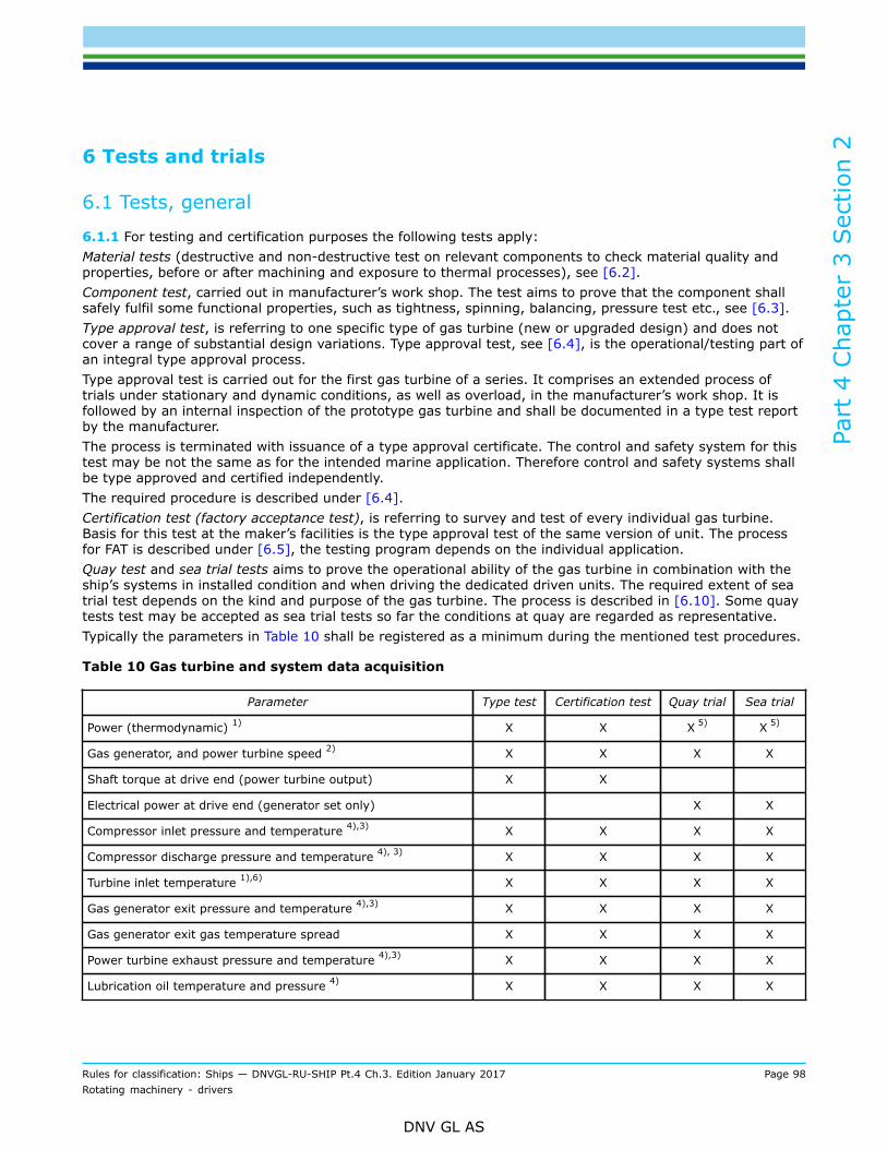
Part
4 C
hapt
er 3
Sec
tion
2
Rules for classification: Ships — DNVGL-RU-SHIP Pt.4 Ch.3. Edition January 2017 Page 98Rotating machinery - drivers
DNV GL AS
6 Tests and trials
6.1 Tests, general
6.1.1 For testing and certification purposes the following tests apply:Material tests (destructive and non-destructive test on relevant components to check material quality andproperties, before or after machining and exposure to thermal processes), see [6.2].Component test, carried out in manufacturer’s work shop. The test aims to prove that the component shallsafely fulfil some functional properties, such as tightness, spinning, balancing, pressure test etc., see [6.3].Type approval test, is referring to one specific type of gas turbine (new or upgraded design) and does notcover a range of substantial design variations. Type approval test, see [6.4], is the operational/testing part ofan integral type approval process.Type approval test is carried out for the first gas turbine of a series. It comprises an extended process oftrials under stationary and dynamic conditions, as well as overload, in the manufacturer’s work shop. It isfollowed by an internal inspection of the prototype gas turbine and shall be documented in a type test reportby the manufacturer.The process is terminated with issuance of a type approval certificate. The control and safety system for thistest may be not the same as for the intended marine application. Therefore control and safety systems shallbe type approved and certified independently.The required procedure is described under [6.4].Certification test (factory acceptance test), is referring to survey and test of every individual gas turbine.Basis for this test at the maker’s facilities is the type approval test of the same version of unit. The processfor FAT is described under [6.5], the testing program depends on the individual application.Quay test and sea trial tests aims to prove the operational ability of the gas turbine in combination with theship’s systems in installed condition and when driving the dedicated driven units. The required extent of seatrial test depends on the kind and purpose of the gas turbine. The process is described in [6.10]. Some quaytests test may be accepted as sea trial tests so far the conditions at quay are regarded as representative.Typically the parameters in Table 10 shall be registered as a minimum during the mentioned test procedures.
Table 10 Gas turbine and system data acquisition
Parameter Type test Certification test Quay trial Sea trial
Power (thermodynamic) 1) X X X 5) X 5)
Gas generator, and power turbine speed 2) X X X X
Shaft torque at drive end (power turbine output) X X
Electrical power at drive end (generator set only) X X
Compressor inlet pressure and temperature 4),3) X X X X
Compressor discharge pressure and temperature 4), 3) X X X X
Turbine inlet temperature 1),6) X X X X
Gas generator exit pressure and temperature 4),3) X X X X
Gas generator exit gas temperature spread X X X X
Power turbine exhaust pressure and temperature 4),3) X X X X
Lubrication oil temperature and pressure 4) X X X X

Part
4 C
hapt
er 3
Sec
tion
2
Rules for classification: Ships — DNVGL-RU-SHIP Pt.4 Ch.3. Edition January 2017 Page 99Rotating machinery - drivers
DNV GL AS
Parameter Type test Certification test Quay trial Sea trial
Fuel temperature and pressure, at the fuel inlet X X X X
Hydraulic fluid pressure X X
Coolant temperature and pressure 4) X
Temperature of external surfaces of the gas turbine X X
Bearing metal temperatures 7) X X X X
Intake pressure loss X X X
Exhaust pressure loss X X X
Vibration levels X X X X
Position of variable stator vanes, or bleed valve opening, asapplicable X X X
1) To be corrected to standard reference conditions (ISO 2314). Note that both raw and corrected parameters shall berecorded.
2) If more spools are involved, their respective speed shall be recorded.3) These values may be derived values from other measured points.4) At locations specified by the manufacturer.5) May be substituted by torque measurement at power turbine output.6) Measurement not required, calculation acceptable.7) Lubricating oil temperature measurement after bearing is also acceptable.
6.2 Testing of material and components
6.2.1 Material certificates for the components listed in Table 11 shall be provided. Agreements related to themanufacturing procedures and suppliers shall be agreed on in each case. The extent of tests shall at leastcomply with the approved quality scheme of the manufacturer.
6.2.2 Non-destructive examinationNon-destructive examination shall be applied to the rotors, blades, disks and welded joints of rotating partsunless another production control process has been agreed or welded joints. The examination shall beperformed by the manufacturer and the results together with details of the test method shall be evaluatedaccording to recognised criteria of acceptability and documented in the test report.
Table 11 Certification requirements for gas turbines and its components
ObjectCertificate
typeIssued
byCertificationstandard*
Additional description
Blades MC Society
Impellers MC Society
Shafts MC Society
Disks MC Society
Tie Bolts MC Society
Combustors MC Society

Part
4 C
hapt
er 3
Sec
tion
2
Rules for classification: Ships — DNVGL-RU-SHIP Pt.4 Ch.3. Edition January 2017 Page 100Rotating machinery - drivers
DNV GL AS
ObjectCertificate
typeIssued
byCertificationstandard*
Additional description
Fuel nozzles MC Society
Casing (gas generator) MC Society
Casing (power turbine) MC Society
Labyrinth seals MC Manufacturer
Anti-frictional bearings MC Manufacturer
Alarm and monitoring system PC Society See Ch.9
Safety system PC Society See Ch.9
Speed control/governor PC Society See Ch.9
* Unless otherwise specified the certification standard is the rules.
6.2.3 For general certification requirements, see Pt.1 Ch.3 Sec.4.
6.2.4 For a definition of the certification types, see Pt.1 Ch.3 Sec.5.
6.3 Tests on components (manufacturer’s works)
6.3.1 The following component tests shall be performed for every gas turbine:
— Pressure and tightness test
Turbine casings shall be tested with 1.5 times the design pressure. Design pressure is the highest expectedpressure within the casing under nominal operating conditions (at least 1.25 times maximum allowableworking pressure under nominal conditions).The tightness test of the turbine casing may be replaced by other alternative means with the agreement ofthe Society.Further pressure equipment, such as coolers, heat exchangers, etc. shall undergo a pressure test with 1.5times of their design pressure.
— Rotor balancing
Before final installation all completed rotors including mounted discs shall be dynamically balanced. Thebalance procedure as well as the results before and after balancing shall be documented. For assessment DINISO 1940 or comparable regulations may be used.
— Cold overspeed test
Turbine and compressor wheels shall be tested at a speed at least 15% above the rated speed for not lessthan three minutes.The Society may accept mathematical proof of the stresses in the rotating parts at overspeed as a substitutefor the overspeed test itself provided that the design is such that reliable calculations are possible and therotating parts have been subjected to thorough non-destructive testing to ascertain their freedom fromdefects.
Part
4 C
hapt
er 3
Sec
tion
2
Rules for classification: Ships — DNVGL-RU-SHIP Pt.4 Ch.3. Edition January 2017 Page 101Rotating machinery - drivers
DNV GL AS
6.4 Type approval test (manufacturer’s works)6.4.1 Type approval test procedureType testing serves the primary purpose of substantiating the gas turbine’s design documentation. It isfurthermore intended to validate that the gas turbine shall provide acceptable performance under the worst-case operational conditions of its intended service.
6.4.2 The complete type testing program is subject to approval. The tests shall be witnessed by the Society,however, the precise extent shall be agreed in each case. In case of proven and already introduced gasturbines, a report of the type test may be accepted by the Society as substitute of new type test, so far thescope of type test is complete and in accordance to these rules, the test has been verified by another thirdparty and the complete documentation is handed over to the Society for appraisal and reference purposes.
6.4.3 Type testing is valid for only one specific type of gas turbine, and does not cover a range of designvariations. The maximum speeds of the spools, firing temperature, turbine inlet temperature, exhausttemperatures, mass flow rate, etc. are fixed for a given type of turbine, and shall be specified on the typeapproval certificate.
6.4.4 Type testing shall preferably be made with the type of fuel oil for which the gas turbine is intended, orequivalent. If this is not possible then there shall be prior agreement with Society as to the fuel used for thetest, and its consequences to the results of the test. For gas turbines intended for running on heavy fuel oil,the test verification of the gas turbine’s suitability for this may be postponed to the sea trial.
6.4.5 If no special turbine application considerations apply (such as e.g. fitness for purpose testing,significant application limitations, or extensive relevant operational experience), the type test program shallbe arranged as outlined in [6.5]. If special considerations apply, the test program shall be agreed betweenthe Society and the manufacturer on a case by case basis, but shall be based on the elements in [6.5].
6.4.6 If a type tested gas turbine that has proven reliability in service, is design approved for an increase ofpower by less than 5%, and does not require internal (manufacturer) design review, a new type test is notnecessary. The percentage refers to increases since the last type testing, not to the last approved level. Itis assumed that the original design calculation of the gas turbine has taken into consideration the intendedincrease in power.
6.4.7 All test results shall be corrected to standard reference conditions as defined by ISO 2314. The typetest shall be performed as close to standard reference conditions as possible in order to minimise correctionerrors.
The method for correction of parameters could be as described by ISO2314, or an accepted manufacturerdeveloped alternative
The standard reference conditions are (ISO 2314):
Temperature = 15°CHumidity = 60% relativeBarometric pressure = 1.013 bar (760 mmHg).
6.4.8 Control settings of the gas turbine, such as alarm and shutdown shall be agreed upon with the Society.Set points that shall be used in the test that are inappropriate in relation to those used in normal runningrequire written agreement.
6.4.9 Variation in control parameters (compressor discharge temperature, turbine inlet temperature, etc.)during data acquisition shall not exceed ±1% (or the manufacturer’s specification.). Shaft power shall notvary more than 3% (or that agreed upon in the contract specification).

Part
4 C
hapt
er 3
Sec
tion
2
Rules for classification: Ships — DNVGL-RU-SHIP Pt.4 Ch.3. Edition January 2017 Page 102Rotating machinery - drivers
DNV GL AS
6.4.10 If during the test, the observed data is obviously inconsistent with expected data or outside ofspecifications from the manufacturer, all possible effort shall be made to rectify the inconsistency during thetesting. This shall be done in a mutually agreed upon manner between the manufacturer and the Society.Failure to reach an agreement shall require a retest.Even if the inconsistency is rectified during the test, a re-test or test extension shall be required by theSociety.
6.4.11 When measured test parameters do not conform with design specification (e.g. high temperaturespread), then formal changes in the design specification shall be documented before acceptance shall begiven for the test. If not, the test shall be considered as failed.
6.4.12 Test data shall be recorded only after steady state conditions have been reached by the gas turbine,for the specific test point. Steady state is achieved when all key control parameters of the gas turbine havereached a steady state for that specific test condition. Steady conditions shall be defined for the specific testarrangement; load fluctuations shall not exceed 3% of the nominal values, registering of data shall reflectmean values over a period of at least 2 min after reaching stationary conditions.
6.4.13 For gas turbines driving electric generators, the requirements in Sec.1 [5.4] shall be verified bytesting.
6.5 Type testing program
6.5.1 It is assumed that:
1) The investigations and measurements required for reliable gas turbine operation have been carried outduring internal tests, according to the manufacturer established and documented procedures.
2) As a final validation of a new gas turbine design, the gas turbine shall be tested at the limit of theintended operation, see the guidance note.The length of the validation testing shall in each case be determined based on the extent of designchanges from parent gas turbine, but 100 hours shallbe considered as minimum. No major faults shalloccur during this test.After the completion of the test, the gas turbine shall be dismantled for inspection. Test procedure andreport shall be submitted to the Society for approval.
Guidance note:Thermal stress cycles obtained by idle (or start) – full load – idle (or stop) sequences are a decisive design criterion andmay be limiting for the total lifetime of the unit. Since this start-stop sequence is determining the amplitude of the thermalstresses, the type test should include several procedures for checking purposes. The number of start-full load-stop cyclesshould be demonstrated during type test and agreed upon with the Society within the approval procedure of the type testprogram. The purpose of this test should validate the design concept.
---e-n-d---o-f---g-u-i-d-a-n-c-e---n-o-t-e---
3) Design assessment acceptance by the Society has been obtained for the gas turbine in question basedon documentation requested, and the Society has been informed about the nature and extent ofinvestigations carried out during the pre-production stages.
6.5.2 Type approval of gas turbines involves the following type tests: start test, mechanical running test,and performance test. These tests shall be carried out in the presence of the Society. They may be conductedseparately, or be integrated so as to combine items from the three tests into one.The recorded test results shall be endorsed by the attending surveyor upon completion of the type test.
6.5.3 Before and after the test, the lubricating oil shall be sampled for testing of contamination of metallicwear particles. The result shall be in accordance with the specification of the manufacturer.

Part
4 C
hapt
er 3
Sec
tion
2
Rules for classification: Ships — DNVGL-RU-SHIP Pt.4 Ch.3. Edition January 2017 Page 103Rotating machinery - drivers
DNV GL AS
6.5.4 Functional tests and collection of operating values including test hours shall be documented in the testreport. The relevant results shall be presented to attending surveyor during the type test.
6.5.5 Component inspections after completion of the test program shall be conducted or witnessed by theSociety, see [6.4.3].
6.5.6 The gas turbine designer shall compile results in a type test report, which shall be submitted forapproval. If deviation from design specifications exists, this shall be agreed upon between the gas turbinedesigner and the Society.For emergency operating situation, the following tests shall be performed:
— quick start— override functions— test run at emergency (or peak) rating (10 minutes).
6.5.7 Start testSeven starts shall be carried out, of which one start shall be preceded by at least a two-hour gas turbineshutdown. There shall be at least one false gas turbine start, pausing for the manufacturer's specifiedminimum fuel drainage time, before attempting a normal start. There shall be at least three normal restartswith not longer than 15 minutes (unless otherwise stated) since gas turbine emergency shutdown. Allvariations of pre-programmed start sequences shall be tested (e.g. quick start if applicable).
6.5.8 Starts done during the type tests can be incorporated in the start test to reach the sum of seven,provided that time interval between consecutive restarts are according [6.5.6].
6.5.9 Gas turbine emergency shutdownThe following emergency shut-downs shall be tested:
a) hot shutdown, at full load (as soon as permitted by the manufacturer's instructions). Restart shall beachieved before lockout and within 30 minutes
b) failure to ignite, resulting in aborted start sequencec) flame out.
6.5.10 Testing of abnormal operationTesting of operation at the limits of the protection system (set points for step to idle and shutdown) shall beperformed including testing the power turbine overspeed limit.
6.5.11 Lubricating oil pressure and temperature shall be monitored and recorded during the test. Theparameters shall be within the manufacturer's recommended values. The recommended values shall bestated in the operating instructions.
6.5.12 The lubricating oil filtration shall be as specified by the manufacturer.
6.5.13 The control and monitoring system used in the test shall be representative of the type approvedcontrol and monitoring system, to the extent related to the gas turbine (see [5.1]). Deviations from the typeapproved control and monitoring system, and the reasons for the changes shall be presented to the Societyin due time before testing.
6.5.14 The test shall document the lateral vibration behaviour in the range 0% to 100% of rated speed forall gas generator shafts. Vibration levels shall be recorded from 0% to 100% of rated shaft speed, down toidle, and finally through coast down and stop.If 100% speed cannot be obtained due to ambient conditions, documented results from previous tests cansubstantiate the verification of upper speed range vibrations.The measurements shall provide a reasonable match with analyses.

Part
4 C
hapt
er 3
Sec
tion
2
Rules for classification: Ships — DNVGL-RU-SHIP Pt.4 Ch.3. Edition January 2017 Page 104Rotating machinery - drivers
DNV GL AS
The Society may require additional measurements at certain specific speeds. In such cases, the readingsshall be taken at steady state conditions.
6.5.15 The manufacturer shall provide the Society with the vibration acceptance criteria that shall be usedduring the test.
6.5.16 Broadband vibration measurements with frequency analyses presented by cascade plots shall beperformed in addition to order tracking measurements.
6.5.17 The mechanical running test shall be considered complete if no damage occurs to the turbine, andtested functions and operating parameters are within specified limits and the vibration requirements aremet. If, after the test, modifications to the design are considered necessary, a complete new test shall beperformed.
6.5.18 Performance test, see [2.3.7].The performance test shall be carried out in a manner equivalent to standards recognised by the Society, e.g.ISO 2314 Gas turbines acceptance tests or ANSI and ASME PTC 22 Gas turbine power plant, performancetest codes. In the case of conflict between the standards and these rules, the rules prevail.A leak check shall be performed prior to all runs.The gas turbine shall be operated according to an estimated power/speed curve for the intended application(e.g. a waterjet curve for mechanical propulsion drive).The data to be measured and recorded when testing the gas turbine at the various load points, and shallinclude all major parameters for the gas turbine operation (see also [6]). The operating time per load pointdepends on the gas turbine size (achievement of steady state condition) and on the time for collection of theoperating values.At least 4 load points shall be tested with approximately equal intervals (between 50% and 100% load).The gas turbine shall be tested for at least 4 hours at maximum load as limited by the control system. Theload shall not be limited by factors external to the gas turbine (e.g. test cell capacity).For high speed, light craft and naval surface craft application, further testing may be required under certaincircumstances, and shall be mutually agreed upon between the Society and the manufacturer.gas turbine and control system shall demonstrate trouble free running without load for a minimum of 20minutes, before testing at load conditions.
6.5.19 The acceleration and deceleration test of the gas turbine according to the manufacturer internalprocedure shall be witnessed by the Society. The parameters of the control system governing thesesequences shall be in compliance with the approved sequences and time constants.
6.5.20 For dual fuel installations, the performance test shall be carried out using the least favourablefuel. Gas turbines intended for dual fuel service shall demonstrate the capability to change from onefuel to the other, e.g. liquid to gas, and vice versa, while at load specified in operating manual, withoutdetrimental change in operational parameters. For the purposes of type approval representative tests shall bedemonstrated for both kinds of fuel. The certification test (see [6.5]) may be applied as operational test forthe second kind of fuel.
6.5.21 Any deviations to the gas turbine internals, e.g. blades, disks, combustors, bearings, etc. from thatsubmitted to the Society during the design review, shall be presented to the Society in due time before theactual test. The deviations shall be recorded in the test report. Additional testing and measurements maybe required by the Society should there be significant changes to critical components e.g. blades, disks,combustors, bearings, etc.
6.6 Inspection of condition of parts (Borescope/tear down)
6.6.1 Borescope inspection shall be conducted following both type and certification test (FAT).

Part
4 C
hapt
er 3
Sec
tion
2
Rules for classification: Ships — DNVGL-RU-SHIP Pt.4 Ch.3. Edition January 2017 Page 105Rotating machinery - drivers
DNV GL AS
Borescope inspection may be required by the Society after sea trial.
6.6.2 No cracks or major wear shall be seen in rotating parts after testing of a new gas turbine. Minorcracks, indents or tear in uncritical stationary parts may be accepted based on documented acceptancecriteria.Borescope inspection of the following parts shall be conducted to the extent allowed by gas turbine design(e.g. Borescope ports placement):
— compressor (blades and nozzles)— combustor— fuel burners— gas generator turbines (blades and nozzles)— power turbine (blades and nozzles).
Proper instruments and necessary personnel shall be on site during the inspection.
6.6.3 The Borescope inspection shall be taped or photographed, as documentation during the inspection.Documentation shall be retained at the manufacturers, and made available to the Society upon request. Thetaped final Borescope inspection is part of the final report to the type test. It may be also requested for thecertification test (FAT) and after endurance test during sea trials.
6.6.4 Further inspection up to and including tear-down of the turbine may be required by the attendingsurveyor, should there be cause to do so, such as damaged blades or nozzles, or any other parts mentionedin the Borescope inspection. Tear-down may also be required, should the turbine fail its test due to notmeeting performance requirements, not meeting manufacturer’s specification, or if required by the surveyor.After type test run sensitive parts of the gas turbine shall be visually inspected after dismantling. The extentof dismantling shall be agreed upon between Manufacturer and Society individually. But the dismantlingshould be at least such, that a visual inspection of blading, bearings and internal part of casing is feasible.
6.6.5 A report summarising findings from inspection and tear-down shall be submitted for information, partof the report is also the documentation of the Borescope taping.
6.7 Certification testing (FAT, manufacturer’s works)6.7.1 Certification testing procedureEach gas turbine to be certified shall be tested in the factory. The purpose of the factory testing shall verifythe design premises such as performance, safety (against fire), adherence to maximum temperatures,speeds, pressures, functionality and product quality.
6.7.2 The test bed shall be equipped in a way to provide adequate measuring data for documentation andreporting purposes (see Table 8).
6.7.3 The gas turbine manufacturer shall prior to testing document that all instrumentation is calibrated. Thegas turbine manufacturer shall compile all results in a test protocol that shall be endorsed by the attendingsurveyor and submitted to the Society for later reference.
6.7.4 The certification test shall include vibration measurements. Steady state vibration levels shall berecorded for different speeds and outputs, in accordance to the manufacturer’s specification.The manufacturer shall provide the Society with the vibration acceptance criteria that shall be used duringthe test.
6.7.5 The control and monitoring systems used in the test shall be representative of the type approvedcontrol and monitoring system, to the extent related to the gas turbine. Deviations from the type approvedcontrol and monitoring system, and the reasons for the changes shall be presented to the Society in due timebefore testing.

Part
4 C
hapt
er 3
Sec
tion
2
Rules for classification: Ships — DNVGL-RU-SHIP Pt.4 Ch.3. Edition January 2017 Page 106Rotating machinery - drivers
DNV GL AS
6.7.6 For case by case approved gas turbines the workshop testing may be extended up to the full typetesting if found necessary by the Society.
6.7.7 Certification testing shall be performed on the complete gas turbine. In the case that the gas generatorand the power turbine have been tested separately, the Society accepts that the certification testing of thecomplete gas turbine is performed on board (see [6.10]).
6.7.8 The complete intended test procedure (performance), including description of measuring capabilitiesof test bed, description of safety and control system of test bed and extent of reporting (tables) shall besubmitted to the Society in advance for approval.
6.7.9 Any deviation to the gas turbine design and gas turbine dressing from that of the type test shall bestated in the test report, together with the reason for the changes.
6.8 Certification test program
6.8.1 The certification test shall include testing found necessary by the Society to demonstrate:
— starting, idling, acceleration, deceleration, stopping— safe operating characteristics throughout its specified operating envelop.
The certification test shall simulate the conditions in which the gas turbine is expected to operate in service,including typical start-stop cycles and load points.The gas turbine shall be run for at least 90 minutes at the maximum continuous power in service.
6.8.2 Prior to the start of the certification test, the gas turbine and the control and monitoring system shalldemonstrate trouble free running at no load for 20 minutes.
6.8.3 Before and after test, lube oil shall be sampled for testing of contamination of metallic wear particles.The result shall be in accordance with the specification of the manufacturer.
6.8.4 Test profile for propulsion gas turbineThe gas turbine shall be tested at power levels to be agreed upon with the Society. The number of steadypoints of operation shall be sufficient to establish gas turbine’s characteristic operational values in accordanceto the intended application (see below). Prolonged operation at the 100% point is required for certificationpurposes. The operating time per load point depends on the gas turbine size (achievement of steady statecondition) and on the time for collection of the operating values. To be agreed prior to testing.
Guidance note:The steady state points are typically 100%, 90%, 75%, 50%, 25% and 10% of gas turbine’s output (load). Additionally prove ofoverload operation (110%) is required. The set speed for the power turbine should follow the application.
---e-n-d---o-f---g-u-i-d-a-n-c-e---n-o-t-e---
The propeller curve based on the propeller law (variable revolutions)This applies if driving a fixed pitch propeller, water jet or controllable pitch propeller with variable r/min andpitch limited to nominal value, or other combinatory curve.
a) At constant speedThis applies if driving a controllable pitch propeller with constant speed or an electric generator forpropulsion.
b) For gas turbines driving generators an additional test of dropping load from 100% to 0% is required. Thistest aims to prove that the gas turbine shall not trip due to overspeed in the case of sudden load drop. Itis recommended to apply same test for gas turbines driving water jets. It shall not trigger the overspeedprotection function (no trip).

Part
4 C
hapt
er 3
Sec
tion
2
Rules for classification: Ships — DNVGL-RU-SHIP Pt.4 Ch.3. Edition January 2017 Page 107Rotating machinery - drivers
DNV GL AS
Guidance note:The precise test details should take test facility capabilities into account. If the facilities are incapable of providing the load shed,alternative solutions may be agreed with the Society.
---e-n-d---o-f---g-u-i-d-a-n-c-e---n-o-t-e---
6.8.5 Test profile for gas turbine driving electrical generatorIn addition to the tests described above [6.8], the requirements in Sec.1 [5.2.2] shall be verified by testingincorporating the intended type of generator. If this cannot be done in the workshop, the test shall bepostponed to shipboard testing.In case the tests were carried out in the type testing (see [6.5]) with the intended type of generator, the testcan be waived.
6.9 Inspection of condition of parts (Borescope)
6.9.1 For type approved gas turbine, after conducting of FAT in accordance to [6.8], Borescope inspection isrequired. The scope of the inspection may be reduced, compared to the type approval procedure, see [6.6],in agreement with the attending surveyor.
6.9.2 A taped report for the Borescope inspection shall not be required. The attending surveyor shall confirmcarrying out of Borescope inspection. Tear out for visual check of parts shall not be required by the Societyfor type approved gas turbines, and so far Borescope inspection is carried out to the satisfaction of thesurveyor.
6.10 Shipboard trials
6.10.1 Gas turbines, subject to certification, shall be tested after installation when connected to the ship’ssystems and driven units. Additionally the control, monitoring and safety system of the installation shall onlyin exceptional cases be the same as the manufacturer’s test bed equipment. Aim of the shipboard trials shallprove safe and reliable operation in the dedicated marine environment but also to enable testing under allpossible operating conditions.
6.10.2 Although all required tests for final certification could be checked during sea trials, it may be agreedupon with the Society to verify the correct functioning under low load, idling or even standstill conditions ofthe propulsion plant.
Guidance note:For logistic but also to reduce risks during sea trials, many tests are carried out at the quay. Typically, operational tests for turbinedriven generators may be carried out at the quay, while for direct propulsion units, sea trial remain the only alternative for highload or dynamic condition testing. For the purposes of approval by the Society only the sea trial schedule shall be submitted forapproval. Quay tests may be accepted as final trials, as far as operation of the ship on sea is irrelevant for the applied criteria. Thiscan be agreed upon with attending surveyor, separate submission of a Quay Trial program for approval purposes is not required,but should be reviewed on application.
---e-n-d---o-f---g-u-i-d-a-n-c-e---n-o-t-e---
6.10.3 Quay testing after or during installation shall focus on typical installation items, which cannot easilybe traced back in case of occurrence of malfunctions during sea trials. Such are alarms, safety and controlfunctions, cleanliness and availability of lubricants etc. Additionally, low load or idling operation of the gasturbine, so far applicable, may give the opportunity for first operational tests, correct supply lines, checkingof sensors. For generator turbines further load sharing matters and speed control behaviour may be checked.
6.10.4 Sea trial procedureThe sea trial procedure shall be approved by the Society prior to testing.
Part
4 C
hapt
er 3
Sec
tion
2
Rules for classification: Ships — DNVGL-RU-SHIP Pt.4 Ch.3. Edition January 2017 Page 108Rotating machinery - drivers
DNV GL AS
The sea trial shall include testing found necessary by the Society to demonstrate:
— starting, idling, acceleration, deceleration, stopping— safe operating characteristics throughout its specified operating envelope.
The sea trial shall simulate the conditions in which the gas turbine is expected to operate in service, includingtypical start-stop cycles.As a minimum, the gas turbine shall be run for 4 hours at the maximum continuous power in service.For gas turbine installations incorporating back-up or emergency fuel supply and lubrication oil supply, thechangeover of supplies shall be tested. Changeover of fuel supply shall be performed at full load.There shall be at least one false gas turbine start, pausing for the manufacturer's specified minimum fueldrainage time, before attempting a normal start. Minimum time required for restart of gas turbine shall bechecked in order to verify that start can be achieved before thermal interlock occurs.
6.10.5 Vibration measurementsThe sea trial shall include vibration measurements.During sea trials vibration measurements shall be performed for the gas turbine. The measurements shall becarried out according to the manufacturer’s specification and aim to prove normal operation in comparison tothe limits given by the maker and the results of the measurements of the type test and FAT.In case of doubts or observation of abnormally high vibrations, especially of fast rotating shafts and theirsupports, the attending surveyor may require more sophisticated measurements, including frequencyanalysis and other techniques in order to detect and eliminate the causes.
Guidance note:Especially for fast turning parts unbalances and incorrect alignment may be a main cause for vibrations, highly amplified, in casesof vicinity of a bending resonance. These effects may be traced back also under low load conditions, since mainly dependable onthe revolutions. For this reason checking of the plant at the quay for such vibrations, before sea trials, is highly recommended, sofar the gas turbine can be run at variable speed without load.
---e-n-d---o-f---g-u-i-d-a-n-c-e---n-o-t-e---
In special cases where the installation is of such character that the dynamic characteristic can be consideredidentical with the certification test set-up, only order tracking measurements shall be required.The manufacturer shall provide the Society with the vibration acceptance criteria that shall be used duringthe test (see also [5]).
6.10.6 The acceleration and deceleration of the gas turbine shall be witnessed by the Society. Theparameters of the control system governing these sequences shall be that of the sequences and timeconstants covered by the type approval.
6.10.7 The temperature of hot surfaces shall be checked during full load testing, except when the gasturbine is fitted in an enclosure, see [2.4]. Where surface temperatures exceed 220°C, remedial actions asdescribed in [2.4] are required. It is advised to use thermographic analyses for documentation.
6.10.8 Sea trial of mechanical drive propulsion gas turbinesIn addition to the test profile defined in [6.8] the gas turbine shall be tested at power levels agreed withthe Society prior to the sea trial. The number of points shall be sufficient to establish the speed – powerrelationship.Crash-stop conditions shall be tested from full speed ahead, this shall be performed in the fastest timepermitted by the controls of the gas turbine .
6.10.9 Sea trial of gas turbines for generating setsTests as necessary to verify requirements in Ch.2 Sec.4 shall be carried out if not performed duringcertification test or type test together with the actual generator. Such trials may be also carried out as quaytests, with full installed power sharing, control and safety equipment. However, if the generator sets areserving propulsion motors, an additional final test under sea trials conditions is required (esp. load sharing,drop of load).

Part
4 C
hapt
er 3
Sec
tion
2
Rules for classification: Ships — DNVGL-RU-SHIP Pt.4 Ch.3. Edition January 2017 Page 109Rotating machinery - drivers
DNV GL AS
6.10.10 Sea trials of gas turbines for high speed, light craft and naval surface craftFor high speed, light craft and naval surface craft, the test shall include full speed turn (shortest radius) inboth port and starboard directions. Vibration levels shall not increase significantly.
6.10.11 Inspection after sea trialsA Borescope inspection may be required by the Society. In such case, and if the behaviour of the gasturbine does not call for further inspections, it is recommended to focus the Borescope inspection on alreadyregistered files of the FAT for the same unit (see also [6.9]).
Part
4 C
hapt
er 3
Sec
tion
3
Rules for classification: Ships — DNVGL-RU-SHIP Pt.4 Ch.3. Edition January 2017 Page 110Rotating machinery - drivers
DNV GL AS
SECTION 3 STEAM TURBINES
1 General
1.1 Application
1.1.1 The requirements in this section apply to steam turbines used for the functions listed in Ch.2 Sec.1[1.1]. The steam turbines are subject to certification, installation survey and shipboard testing.
1.1.2 The rules in [2] to [5] apply to the turbine, its components and its internal systems. The rules in [6] to[9] apply to the installation and the shipboard testing.
1.2 Certification requirements
1.2.1 Products shall be certified as required by Table 1.
Table 1 Certification requirements
Object Certificate type Issued by Certification standard* Additional description
Steam turbine PC Society
* Unless otherwise specified the certification standard is DNV GL rules
1.2.2 For general certification requirements see Pt.1 Ch.3 Sec.4.
1.2.3 For a definition of the certificate types see Pt.1 Ch.3 Sec.5.
1.3 Documentation requirements - manufacturer
1.3.1 The manufacturer shall submit the documentation required by Table 2. The documentation shall bereviewed by the Society as a part of the class contract.
Table 2 Documentation requirements for the manufacturer
Object Document type Additional description Info
C020 − Assembly or arrangementdrawing
General arrangement including internalarrangement FI, TA
Steam turbineC020 − Assembly or arrangementdrawing
Longitudinal cross-section showing rotor(s),bearings, seals, casings FI, TA
C030 − Detailed drawing Giving all details for calculation of critical speed(propulsion turbine only) AP, TA
Rotor
C040 − Design analysis Calculation of critical speeds (propulsion turbineonly) AP, TA
Blade C020 − Detailed drawing Including fastening device (propulsion turbineonly) FI, TA
Casing C030 − Detailed drawing FI, TA

Part
4 C
hapt
er 3
Sec
tion
3
Rules for classification: Ships — DNVGL-RU-SHIP Pt.4 Ch.3. Edition January 2017 Page 111Rotating machinery - drivers
DNV GL AS
Object Document type Additional description Info
Seating C030 − Detailed drawing See Ch.2 FI, TA
Steam flow S010 − Piping diagram Including supply and exhaust points FI, TA
Lubrication oilsystem S010 − Piping diagram AP, TA
AP = For approval; FI = For information; TA = Covered by type approval
1.3.2 For general requirements for documentation, including definition of the info codes, see Pt.1 Ch.3 Sec.2.
1.3.3 For a full definition of the documentation types, see Pt.1 Ch.3 Sec.3.
1.3.4 For details about NDT specification, see Ch.2 Sec.1 [3.1.2].
1.4 Documentation requirements - builder
1.4.1 The builder shall submit the documentation required by Table 3. The documentation shall be reviewedby the Society as a part of the certification contract.
Table 3 - Documentation requirements - builder
Object Documentation type Additional description Info
Propulsionarrangement
C040 − Design analysis Torsional vibration calculation.See Sec.1 [1] and [7]
AP
AP = For approval
1.4.2 For general requirements for documentation, including definition of the info codes, see Pt.1 Ch.3 Sec.2.
1.4.3 For a full definition of the documentation types, see Pt.1 Ch.3 Sec.3.
2 Design
2.1 General
2.1.1 For general design principles concerning machinery, see Ch.2 Sec.3. Special attention should be paid toCh.2 Sec.3 [1.1.2]. For general design requirements regarding piping and ancillary equipment, such as pipes,filters, coolers etc., see Ch.6 and Ch.7, as found applicable.
2.1.2 Means for going asternThe main propulsion machinery shall possess sufficient power for running astern. The astern power isconsidered to be sufficient if, given free running astern, it is able to attain astern revolutions equivalent to atleast 70% of the rated ahead revolutions for a period of at least 30 minutes.For main propulsion machinery with reverse gearing, controllable pitch propellers or an electrical transmissionsystem, astern running shall not cause any overloading of the propulsion machinery

Part
4 C
hapt
er 3
Sec
tion
3
Rules for classification: Ships — DNVGL-RU-SHIP Pt.4 Ch.3. Edition January 2017 Page 112Rotating machinery - drivers
DNV GL AS
2.2 Component design requirements
2.2.1 Rotors shall have a separation margin of at least 25% (of rated speed) between critical speed andoperating speed range.
2.2.2 Turbines shall be able to withstand the temperature variations that can arise when starting, stoppingand manoeuvring.
2.2.3 The pipes of the gland-sealing system shall be self-draining, and precaution shall be taken against thepossibility of condensed steam entering the glands and turbines. The steam supply to the gland sealing shallbe fitted with an effective drain trap. In the air ejector re-circulating water system, the connection to thecondenser shall be so located that water cannot impinge on the low pressure rotor or casing.
2.2.4 The casings shall be designed so as to provide containment in case of a blade loss. See Ch.2 Sec.1[2.1.5] This requirement does not exempt the blade fastening from being designed so as to sustain anypermissible over-speed.
2.2.5 All blades and other relevant moving parts shall have sufficiently large axial and radial clearances, sothat no harmful interference with static members can occur under any operating condition.
2.2.6 CondensersThe condenser shall be so designed that the inlet steam speed does not result in prohibitive stressing of thecondenser tubes. Excessive sagging of the tubes and vibration shall be avoided, e.g. by the incorporation oftube supporting plates.The water chambers and steam space shall be provided with openings for inspection and cleaning. Anti-corrosion protection shall be provided on the water side. In the case of single-plane turbine installations,suitable measures shall be taken to prevent condensate from flowing back into the low pressure turbine.
3 Inspection and testing
3.1 General
3.1.1 Products shall be certified as required by Table 4.
Table 4 Certification required
Object Certificatetype Issued by Certification standard* Additional description
Steam turbine PC Society
Rotor MC Society Manufacturer if auxiliary service
Individual discs MC Society Manufacturer if auxiliary service
Couplings MC Society Manufacturer if auxiliary service
Casing MC Manufacturer
Blades MC Manufacturer
Diaphragms MC Manufacturer
Steam valve casings MC Manufacturer
Part
4 C
hapt
er 3
Sec
tion
3
Rules for classification: Ships — DNVGL-RU-SHIP Pt.4 Ch.3. Edition January 2017 Page 113Rotating machinery - drivers
DNV GL AS
Object Certificatetype Issued by Certification standard* Additional description
Coupling bolts TR Manufacturer
Alarm and monitoring system PC Society See Ch.9
Safety system PC Society See Ch.9
Speed control/governor PC Society See Ch.9
* Unless otherwise specified the certification standard is the rules
3.1.2 For general certification requirements, see Pt.1 Ch.3 Sec.4.
3.1.3 For a definition of the certification types, see Pt.1 Ch.3 Sec.5.
3.1.4 The manufacturer shall have a quality control system that is suitable for the type of turbine. This shallalso cover subcontractors.The extent of quality control that shall be documented to the Society by work (W) certificates, or to beinspected and certified by the Society is given in the following.If found necessary, due to service experience, an extended scope of testing and inspection may be required.
3.1.5 Results from the testing and inspection shall be evaluated against the acceptance criteria in theapplicable NDT specifications included in the documents listed in Table 1.
3.1.6 Hydraulic testing applies for both propulsion and auxiliary turbines as given in Table 5.
3.1.7 Devices for the attachment of heat insulation (bolts, hooks, etc.) shall be welded on to the turbinecasing before the final heat treatment of the casing.
3.1.8 All rotors shall be dynamically balanced in minimum two planes.
Table 5 Hydraulic testing
Test pressureComponent
1.5 p 1) 2 p 1)
Comments
Main flow valves x
HP/LP crossover pipe See Ch.6
Turbine casings x May be suitably subdivided. Not less than 2 bar
1) p = working pressure
4 Workshop testing
4.1 General turbine tests
4.1.1 The turbine shall be tested in the workshop and a complete test report shall be given to the surveyor.
4.1.2 Turbines shall undergo running tests that cover the whole speed range up to 110% of rated speed. Forpropulsion turbines this applies to both ahead and astern operation.
Part
4 C
hapt
er 3
Sec
tion
3
Rules for classification: Ships — DNVGL-RU-SHIP Pt.4 Ch.3. Edition January 2017 Page 114Rotating machinery - drivers
DNV GL AS
4.1.3 Vibration levels shall be recorded in the whole speed range (up to 110%) at several speed settings.
4.1.4 The control and monitoring systems shall be tested according to Ch.9 Sec.1 as far as it has beenarranged during the workshop testing.
4.1.5 Both before and after the test a lubricating oil sample shall be tested for traces of metallic particles
4.1.6 A visual inspection of internal parts shall be carried out to the extent as requested by the surveyor.
4.1.7 For main propulsion turbines, the following inspection procedures apply after testing:
— Axial clearances in thrust bearing and clearances between blades and stationary parts shall be checkedby sample testing after the test run. The measured clearances shall be compared with equivalentmeasurements made during assembly, and approved plans.
— The rotors shall be lifted. Bearings, blades, wires and shroud rings shall be examined, and it shall beverified that no damaging contact has taken place between rotating and stationary parts.
Scope of inspection of turbines for purposes other than main propulsion shall be subject to specialconsideration. Opening up shall be required when any abnormalities are discovered during testing.
5 Control and monitoring
5.1 General
5.1.1 The requirements in [5] are additional to those given in Ch.9.
5.2 Speed governing
5.2.1 Turbines shall be equipped with speed governors. For propulsion turbines which incorporate a reversinggear, electric transmission, controllable pitch propeller or other free-coupling arrangement, the governor(s)shall be able to control the speed of any turbine that can become unloaded.For auxiliary turbines driving generators, see Sec.1 [5.2].The speed governors shall be able to control the turbine speed so as to avoid any relevant load shed toactivate the separate overspeed protective device.
5.2.2 In addition to the speed governor, a separate over-speed protection device shall be provided and shallbe adjusted so as to avoid transient speed beyond 115% of rated speed or beyond the permissible transientspeed, whichever is less.Where two or more propulsion turbines are coupled to the same reduction gear, and without any freecoupling device, only one over-speed protection device is required.
5.2.3 For propulsion turbinesAutomatic or semiautomatic control systems shall provide controlled load changes to avoid thermal shocksand other unacceptable transients.
5.3 Safety functions and devices
5.3.1 Arrangement shall be provided for shutting off the steam to the propulsion turbines by suitable handtrip gear situated at the manoeuvring stand and at the turbine itself. Hand tripping for auxiliary turbines shallbe arranged in the vicinity of the turbine over-speed protective device.

Part
4 C
hapt
er 3
Sec
tion
3
Rules for classification: Ships — DNVGL-RU-SHIP Pt.4 Ch.3. Edition January 2017 Page 115Rotating machinery - drivers
DNV GL AS
Guidance note:The hand trip gear is understood to be any device which is operated manually irrespective of the way the action is performed, i.e.mechanically or by means of external power.
---e-n-d---o-f---g-u-i-d-a-n-c-e---n-o-t-e---
5.3.2 Where exhaust steam from auxiliary systems is led to the propulsion turbine, the steam supply shall becut off at activation of the over-speed protective device.
5.3.3 A sentinel valve or equivalent shall be provided at the exhaust end of all turbines to provide warningto personnel in the vicinity of the exhaust end of steam turbines of excessive pressure. The valve dischargeoutlets shall be visible and suitably guarded if necessary. When, for auxiliary turbines, the inlet steampressure exceeds the pressure for which the exhaust casing and associated piping up to exhaust valve aredesigned, means to relieve the excess pressure shall be provided.
5.3.4 Starting interlock shall be provided when turning gear is engaged.
5.4 Monitoring
5.4.1 For monitoring of propulsion steam turbines, see Table 6.
Table 6 Control and monitoring of propulsion turbines
System Item
Gr 1Indication
alarm
load reduction
Gr 2Automatic start
of stand-bypump with alarm
Gr 3Shut downwith alarm
Comment
Inlet pressure (after filter) IR, IL, LA AS SH 1)
Inlet temperature IR, HA
Filter differential pressure IR, HA1.0 Lubricating oil
Level in system tank LA
2.0 Bearings Bearing temperature IR, HA
3.0 Turbine speed Overspeed (LR) SH
LR or SH, ifapplicable, to be
activatedautomatically,
see [5.2]
Vacuum IR, LA SH
Vacuum pump stopped AS
Level IR, HA AS SH
Level IR, LA If non-cavitatingcondensate pump
4.0 Condensersystem
Salinity HA
5.0 Cooling water(main condenser)
Inlet/outlet differentialpressure IR, LA AS

Part
4 C
hapt
er 3
Sec
tion
3
Rules for classification: Ships — DNVGL-RU-SHIP Pt.4 Ch.3. Edition January 2017 Page 116Rotating machinery - drivers
DNV GL AS
System Item
Gr 1Indication
alarm
load reduction
Gr 2Automatic start
of stand-bypump with alarm
Gr 3Shut downwith alarm
Comment
6.0 Slow turningarrangement Overspeed SH
Inlet pressure to turbine IR, LA, HA7.0 Gland steam
Exhaust fan stopped A
8.0 Hydraulicsystem Pressure IR, LA AS
9.0 Vibration Level HA SH
10.0 Rotor Axial displacement IR, HA SH
Gr 1 = sensor(s) for indication, alarm, load reduction (common sensor permitted but with different set points andalarm shall be activated before any load reduction)
Gr 2 = sensor for automatic start of standby pump
Gr 3 = sensor for shut down
IL = local indication – (presentation of values) in vicinity of the monitored component
IR = remote indication – (presentation of values) in engine control room or another centralized control station suchas the local platform/manoeuvring console
A = alarm activated for logical value
LA = alarm for low value
HA = alarm for high value
AS = automatic start of standby pump with corresponding alarm
LR = load reduction, either manual or automatic, with corresponding alarm
SH = shut down with corresponding alarm. May be manually (request for shut down) or automatically executed ifnot explicitly stated above.
For definitions of load reduction (LR) and shut down (SH), see Ch.1.
1) The shut down shall be so arranged as not to prevent admission of steam to the astern turbine for braking.
5.4.2 For monitoring of auxiliary steam turbines, see Table 7.
Table 7 Control and monitoring of auxiliary turbines
System Item
Gr 1Indication
alarm
load reduction
Gr 2Automatic start
of stand-bypump with alarm
Gr 3Shut downwith alarm
Comment
Inlet pressure (after filter) IR or IL, LA SH
Inlet temperature IR or HA1.0 Lubricating oil
Level in system tank LA

Part
4 C
hapt
er 3
Sec
tion
3
Rules for classification: Ships — DNVGL-RU-SHIP Pt.4 Ch.3. Edition January 2017 Page 117Rotating machinery - drivers
DNV GL AS
System Item
Gr 1Indication
alarm
load reduction
Gr 2Automatic start
of stand-bypump with alarm
Gr 3Shut downwith alarm
Comment
2.0 Turbine speed Overspeed SH
SH, if applicable,to be activatedautomatically,
see [5.2]
3.0 Condensersystem Pressure IL or IR, HA SH
4.0 Steam inlet Pressure IL or IR, LA1)
5.0 Rotor Axial displacement IL or IR, HA SH When drivingelectric generator
Gr 1 = sensor(s) for indication, alarm, load reduction (common sensor permitted but with different set points andalarm shall be activated before any load reduction)
Gr 2 = sensor for automatic start of standby pump
Gr 3 = sensor for shut down
IL = local indication – (presentation of values) in vicinity of the monitored component
IR = remote indication – (presentation of values) in engine control room or another centralized control station suchas the local platform/manoeuvring console
A = alarm activated for logical value
LA = alarm for low value
HA = alarm for high value
AS = automatic start of standby pump with corresponding alarm
LR = load reduction, either manual or automatic, with corresponding alarm
SH = shut down with corresponding alarm. May be manually (request for shut down) or automatically executed ifnot explicitly stated above.
For definitions of load reduction (LR) and shut down (SH), see Ch.1.
1) Only for turbines driving generators, may be omitted if LA for boiler steam pressure is provided.
6 Arrangement
6.1 General arrangement
6.1.1 The turbine exterior and the immediate environment shall be such as to prevent conceivable hazardoussituations from occurring.All exterior surface temperature shall be less than 220°C.
6.1.2 Non-return valves, or other approved means that shall prevent steam and water returning to theturbines, shall be fitted in bled steam connections.
6.1.3 The fastening of the turbine shall be designed so as to cope with all forces due to thermal expansion,including inlet and outlet piping. Foundation shall be in compliance with Ch.2 Sec.1 [6].

Part
4 C
hapt
er 3
Sec
tion
3
Rules for classification: Ships — DNVGL-RU-SHIP Pt.4 Ch.3. Edition January 2017 Page 118Rotating machinery - drivers
DNV GL AS
6.2 Arrangement of propulsion machinery
6.2.1 The turbine installation shall allow for efficient changeover between ahead and astern running. Themanoeuvring system shall not cause any harmful effects.
6.2.2 Any probable single failure in any of the turbines shall for an extended period of time not result in lossof manoeuvrability, see [6.2.6].
6.2.3 Provision for turning continuously shall be arranged.
6.2.4 Efficient steam strainers shall be provided close to the inlets to ahead and astern high pressureturbines or alternatively at the inlets to manoeuvring valves.
6.2.5 Propulsion turbines shall be provided with a satisfactory emergency supply of lubricating oil thatshall come into use automatically when the pressure drops below a predetermined value. The emergencysupply may be obtained from a gravity tank containing sufficient oil to maintain adequate lubrication untilthe turbine is brought to rest or by equivalent means. If emergency pumps are used these shall be arrangedso that their operation is not affected by failure of the power supply. Suitable arrangement for cooling thebearings after stopping may also be required.
6.2.6 In single screw ships fitted with cross compound steam turbines, the arrangement shall be such as toenable safe navigation (minimum 40% of full speed along the theoretical propeller curve) when the steamsupply to any one of the turbines is required to be isolated. For this emergency purpose the steam maybe led directly to the L.P. turbine, and either the H.P. or M.P. turbine can exhaust directly to the condenser.Adequate arrangements and controls shall be provided for these operating conditions so that the pressureand temperature of the steam shall not exceed those that the turbine and condenser can withstand safely.Necessary pipes and valves for these arrangements shall be readily available and properly marked.A fit up test is required, see [8.1.2].
Guidance note:With reference to Ch.2 Sec.1 [2.1.5] these possible operation modes need not be tested during sea trial.
---e-n-d---o-f---g-u-i-d-a-n-c-e---n-o-t-e---
The permissible power/speeds when operating without one of the turbines (all combinations) shall bespecified and information provided on board.The operation of the turbines under emergency conditions shall be assessed for the potential influence onshaft alignment and gear teeth loading conditions.
7 Vibrations
7.1 Torsional vibrations
7.1.1 For propulsion plants torsional vibrations calculations comprising the whole plant shall be submitted forapproval.The calculations shall contain determination of natural frequencies and corresponding critical speeds.Regarding assumptions on propeller excitation, see Ch.2 Sec.2 [2.5.9].Speed ranges where gear hammer may occur, shall be barred for continuous operation. See Ch.2 Sec.2 Table5.
Part
4 C
hapt
er 3
Sec
tion
3
Rules for classification: Ships — DNVGL-RU-SHIP Pt.4 Ch.3. Edition January 2017 Page 119Rotating machinery - drivers
DNV GL AS
8 Installation inspections
8.1 General
8.1.1 Alignment between turbine and gearbox shall be checked in the presence of the surveyor.
8.1.2 Proper functioning of safety functions and devices (see [5.3] and [6.2]) shall as far as practicable bechecked prior to the sea trial. A fit up test of all combinations of pipes and valves as required in [6.2.6] shallbe performed prior to the first sea trials.
9 Shipboard testing
9.1 General
9.1.1 The turbines shall be tested according to an agreed programme. Upon completion of the sea trial, thecomplete test report shall be given to the surveyor.
9.1.2 The control, safety and monitoring systems shall be tested according to [5] and Ch.9 Sec.1.
9.1.3 Turbine vibration levels shall be measured at the same positions as in [4.1.3]. The results shallbe compared, and in case of acceptance dispute, frequency analysed in order to eliminate turbine alienfrequencies shall be carried out.
9.1.4 Oil filters shall be examined for metal particles after the sea trial.
9.1.5 The temperature of hot surfaces shall be checked during full load testing. Where surface temperaturesexceed 220°C insulation of non-absorbent material covered by sheet metal shall be fitted. It is advised to usethermographic analyses for documentation.
9.2 Auxiliary turbines
9.2.1 Turbine generator sets shall be tested to verify that requirements in Ch.2 Sec.4 are met.
9.3 Propulsion turbines
9.3.1 The minimum full load test duration is 4 hours ahead and 20 minutes astern.
9.3.2 Gears shall be checked for possible gear hammering. See Ch.4 Sec.2 [9.2].

Part
4 C
hapt
er 3
Cha
nges
– h
isto
ric
Rules for classification: Ships — DNVGL-RU-SHIP Pt.4 Ch.3. Edition January 2017 Page 120Rotating machinery - drivers
DNV GL AS
CHANGES – HISTORIC
July 2016 editionThis document supersedes the January 2016 edition.
Main changes July 2016, entering into force 1 January 2017
• Sec.1 Reciprocating internal combustion engines— Sec.1 [1.1]: The sub-section has been updated to further clarify rule application for engines less than
100kW and for engines not serving main functions or emergency services.— Sec.1 Table 1: The table has been updated to reflect requirements for TA and to clarify certification
requirements depending on engine size and service.— Sec.1 [1.4]: Requirement added for type approval of resilient mounts.— Sec.1 [2.14.1]: Paragraph updated to be in line with IACS UR M71 regarding applicability of Type tests for
in-line and V-engines.— Sec.1 [2.14.2]: Paragraph updated to reflect requirements for engines less than 100 kW.— Sec.1 [3]: Previous sub-section [3.1] regarding recognition of engine manufacturer's workshops has been
removed.— Sec.1 [3.2]: Paragraphs relating to testing of materials and components removed as the requirements are
given in other parts of the rules.— Sec.1 Table 8: The table has been corrected to be in conformance with IACS UR M72 and descriptions of
UT and CD have been added.— Sec.1 [4.1.6]: The paragraph has been updated to reflect scope for engines less than 100 kW.— Sec.1 [4.3]: Added load test requirement at approved intermittent overload in accordance with IACS UR
M51.— Sec.1 Table 9 - item 3.0: Requirement for monitoring of lube oil outlet temperature corrected to >2500Kw
pr cyl group to be in line with IACS UR M72.— Sec.1 Table 10 - item 3.0: Requirements for monitoring of turbocharger oil temperature and pressure
added to be in line with IACS UR M73.— Sec.1 [9.3]: Shipboard trial requirements updated to be in line with IACS UR M51— Sec.1 [10.2.6]: The requirement to install flame arrestors when gas is supplied in a mixture with air
through a common manifold has been removed.— Sec.1 Table 14: Footnotes B) and C) added for Containment test report in order to be in conformance with
IACS UR M73.— Sec.1 [11.1.5]: Paragraphs regarding recognition of manufacturers of turbochargers have been removed.
Paragraph regarding turbochargers manufactured under MSA agreement has been included.
January 2016 editionThis document supersedes the October 2015 edition.
Main changes January 2016, entering into force 1 July 2016
• Sec.1 Reciprocating internal combustion enginesThe section has been updated to align with the following revised and new IACS URs:
— M44 - Documents for the approval of diesel engines— M51 - Factory Acceptance Test and Shipboard Trials of I.C. Engines

Part
4 C
hapt
er 3
Cha
nges
– h
isto
ric
Rules for classification: Ships — DNVGL-RU-SHIP Pt.4 Ch.3. Edition January 2017 Page 121Rotating machinery - drivers
DNV GL AS
— M71 - Type Testing of I.C. Engines— M72 - Certification of Engine Components— M73 - Turbochargers
October 2015 editionThis is a new document.The rules enter into force 1 January 2016.

DNV GLDriven by our purpose of safeguarding life, property and the environment, DNV GL enablesorganizations to advance the safety and sustainability of their business. We provide classification andtechnical assurance along with software and independent expert advisory services to the maritime,oil and gas, and energy industries. We also provide certification services to customers across a widerange of industries. Operating in more than 100 countries, our 16 000 professionals are dedicated tohelping our customers make the world safer, smarter and greener.
SAFER, SMARTER, GREENER