parsec parameterization methodology for enhancing airfoils
TRANSCRIPT

PARSEC PARAMETERIZATION METHODOLOGY FORENHANCING AIRFOILS GEOMETRY USING PSO ALGORITHM
Rafael Alves da S. Neto, [email protected]
Luciano Goncalves Noleto, [email protected]
Josiane do S. Aguiar de Souza, [email protected]
Universidade de Brasılia, Campus Gama
Area Especial, Projecao A, UnB - Setor Leste - Gama, Distrito Federal 72444-240
Antonio Cesar Pinho Brasil Jr.
Universidade de Brasılia, Campus Darcy Ribeiro
Campus Universitario Darcy Ribeiro, Brasılia - DF, 70910-900
Abstract. The electromechanical generating system is mainly based on the characteristicswherein the turbine has to ”harvest” the energy of a working fluid. Thus, the engineeringbehind the blades, such as the geometry and construction, must be effectively consolidated toincrease the overall turbine efficiency. This work aims to go further into the computationalprinciples of modeling the turbine blades, precisely, the hydrokinetic turbine hydrofoil built byLEA (Engineering Laboratory and Environment - UNB). The study has a focus on designingand analyzing, through numerical studies of parameterization and optimization profiles, bladesusing computational tools such as MATLAB R2016b and XFOIL. In this case, the model study ispart of the airfoil theory combined with the Particle Swarm Optimization technic (PSO), whichare implemented to get a maximum utilization of the aerodynamic coefficient CL over CD of theblade. Furthermore, an optimal turbine blade geometry, set by PARSEC parameter, is foundand compared with results obtained from the original hydrofoil, using the software of profileanalysis XFOIL, to certify the mathematical method, proving its effectiveness to parameterizehydrodynamic profiles and optimize their geometries.
Keywords: Hydrokinetic Turbine. Airfoils. Parameterization and Optimization. Parsec. PSO.
CILAMCE 2016Proceedings of the XXXVII Iberian Latin-American Congress on Computational Methods in Engineering
Suzana Moreira Avila (Editor), ABMEC, Braslia, DF, Brazil, November 6-9, 2016

Parsec Parameterization Methodology for Enhancing Airfoils Geometry Using PSO Algorithm
1 INTRODUCTIONThe decentralized structure importance of the energy generation capacity (”smart grids”) is
due to the apparent economic infeasibility in installing electric power transmission lines for alltypes of consumers. For this reason, the study of alternative sources is a key point, for socialreasons, human development and economic issues. Therefore, the use of hydrokinetic machinesdoes not denote an innovative concept, but a review of existing models as an alternative forsustainable and reliable energy generation (Van Els et al, 2003).
The hydrokinetic turbines work with a water flow in a river or ocean. As watermills, thesedevices use hydrofoils as a way to ”harvest” the energy of free streams of a fluid flow, using thedifference in pressure gradient to generate a positive lift on its profile, so that generates torque,and therefore power (Grant, 2009).
In order to improve the overall efficiency of a turbine, the computational numerical datarepresents a faster and efficient way to get solutions, as it has the ability to meet various param-eters from an old experimental database, enabling the scope of new optimized projects within acomputer programming.
However, the description of a hydrofoil geometry is complex due to its parameters, likeleading edge and trailing edge representation, which cannot be representated by a low geomet-rical derivative. For this reason, a great number of coordinates must be applied to the processin order to return a accurately geometry pattern in a computation environment.
Consequently, it is necessary to understand and develop a parameterization methodologyof blade profiles in order to use fewer possible parameters to describe the given geometry incomputational framework, which was explored in this work.
The algorithm generates many solutions, and in one of these solutions, the optimal settingshould be included. Ahead, by an iterative method, the final result is found by the junctionbetween parameterization, optimization and numerical analysis and simulations, to meet theneed of a well-developed computation process, satisfaying topics like:
1. To generate continuous and closer to reality surfaces;
2. It has to be, in computational terms, faster with a certain accuracy and consistency through-out the body of the algorithm;
3. It needs to be able to represent a lot of airfoils with few parameters;
4. Finally, it must have a consistency in the profile creation process, as well as being able tochange the geometry;
These objectives have been described by Kulsan and Bussoletti (2006), and item 3 relatesthe most important criteria in this paper.
2 PARAMETERIZATION METHOLOGY PARSEC/BSPLINERecently, there are many types of parameterization methodologies, mainly applied in aero-
dynamic optimization of aircraft wings.
Analytical functions are a method that is described in many of these studies, because theycan represent airfoils by polynomial representations instead of using high amounts of coordinatepoints.
CILAMCE 2016Proceedings of the XXXVII Iberian Latin-American Congress on Computational Methods in EngineeringSuzana Moreira Avila (Editor), ABMEC, Braslia, DF, Brazil, November 6-9, 2016

Rafael Alves, Luciano Goncalves, Josiane do S. Aguiar, Antonio C. Brasil
Theoretical modeling is done obeying the standards developed in literature and airfoildesign about parameterization and optimization processes. In summary, through the airfoildatabase, the parameterization PARSEC methodology translates the Cartesian coordinates into11 parameters (polar coordinates - Fig. 1), describing any airfoil with high accuracy. It wasfirst studied by Sobiesky (1998) whose work used algebraic and analytical relations to generaterealistic geometries based on airfoil families, such as NACA, GOE, Joukovsky.
Figure 1: 11 Parsec parameters for an airfoil representation.Adapted from Sobieczy (1998)
The 11 parameters are representations of physical characteristics of a given airfoil. More-over, in order to build new profiles based on this specific representation, it would be necessaryto have the description of basis functions for each one of the 11 parameters to recreate new11 viable parameters. Therefore, the integration with a parameterization that does not involvephysical quantities, such as Bspline, was adopted as the basis for the optimization process.
Bspline parameterization is an evolution of Bezier curves described by Consentino (1986).The contrary of Bezier that uses segments of ”functions of Bezier” according to its degree,Bspline curve is defined as a linear combination of control points function and bases to assurethat the curve can be represented in a simple degree polynomial representation and continuity.It was first studied by Shoenberg (1988).
These 11 parameters found by Parsec metholody are then stored for the new airfoils base-line generation by BSpline in parameterization process.
The method used to find the parameters, in this paper, is to use base functions created fromthe LEA turbine foil and solved by a linear system of Minimum Squares Error principle.
The representation of the specific turbine can be made following the expressions:
ye(xe) =6∑
k=1
αekxek− 1
2 (1)
yi(xi) =6∑
k=1
αikxik− 1
2 (2)
αi1 = −αe1 (3)
The profiles characterized by PARSEC parameterization are defined by two polynomialfunctions and one boundary condition, as can be seen. The first two functions describes the
CILAMCE 2016Proceedings of the XXXVII Iberian Latin-American Congress on Computational Methods in Engineering
Suzana Moreira Avila (Editor), ABMEC, Braslia, DF, Brazil, November 6-9, 2016

Parsec Parameterization Methodology for Enhancing Airfoils Geometry Using PSO Algorithm
airfoil boundaries, and the contour determines the leading edge condition. The representationis then used first to determine the base coefficients by the least-square method, each one mini-mized between the original cartesian coordinates represented by x and y variables.
The algorithm followed the method:
1. The derivative form of Eq. (1) is assumed to represent the miminium function for theupper camber solved by the Eq. (4):
y′emax = 0 =6∑
k=1
(k − 1
2)αekxemax
k− 32 (4)
2. The derivative form for the lower camber from Eq. (2) is written in Eq. (5). Moreover,both of these equations are used to state a linear system to solve the arfoil coefficients ’a’,and then, the 11 Parsec parameters:
y′imin = 0 =6∑
k=1
(k − 1
2)αikximin
k− 32 (5)
3. Set the 11 parameters to the Bspline function base in order to randomize new parameters.
4. Each new parameter represents one different airfoil that needs to be analized by a CFDsoftware. For this case, XFOIL software developed by Drela (1989), to find the best one.
5. The optimization algorithm is the one to call the Bspline parameterization to create newairfoils. Then, they go through a iteration process that penalize bad designs and promotethe best ones.
6. The process ends when it can no longer find the best geometry, or when the maximumiteration process is reached.
It is important to ilustrate that the success of any parameterization method is related to howaccurate the calculation can solve the sensitivity derivatives (Li and Padula, 2004). As well, inoder to apply even more realibility, smoothing process in the basis function is used after eachiterations.
3 PSO OPTIMIZATION
Particle Swarm Optimization (PSO) is a optimization process based on stochastic popula-tion technique and it shares many similarities with Genetic Algorithms (GA) although it has noevolution process such as crossover and mutation. It was developed by Dr. Eberhart and Dr.Kennedy in 1995, inspired by the flock of birds behavior or school of fish (Xiaohui Hu, 2006).
Basically, the system is initialized with a population of possible solutions, and it demandsin that universe, the best one, making improvements in each generation. However, contrary tothe GAs, PSO is not an algorithm based on the evolution operators, as already said. Potentialsolutions, also called particles, move within the sample space following ones closer to otherssolution particles. Apart from that, they also have internal memory, a fundamental part in eachiterations.
PSO starts with a group of random particles, in this case, airfoils. Its operation is basedon ”the learning scenario” and uses it to solve the optimization problem. In each space thereare many ”particles” that have fitness values, which are evaluated by a fitness function to be
CILAMCE 2016Proceedings of the XXXVII Iberian Latin-American Congress on Computational Methods in EngineeringSuzana Moreira Avila (Editor), ABMEC, Braslia, DF, Brazil, November 6-9, 2016

Rafael Alves, Luciano Goncalves, Josiane do S. Aguiar, Antonio C. Brasil
optimized (Xiaohui Hu, 2006). The particles also have velocities which help ”the movement”in the space following the current optimum particles. It can be associate with an example givenby Xiaohui (2006) in IEEE Congress on evolutionary Computation: a group of ducks (particles)in a random search, looking for food (objective) in a lake (given space). There is only one placein that given space with food, but the ducks do not know exactly where, even though they feelhow close they are in each iteration. Furthermore, the group of ducks follows that one duckwhich is closer to the main goal.
At the begining, the optimum solution is the airfoil which was set by the user to be opti-mized. Then, this airfoil is parameterized in random solutions and analyzed one by one to setthe second best solution to be followed, which takes place to the first one. The algorithm goeson until it finds the objective value also set by the user.
There are a few variables that need to be used in order to structure the algorithm, mainlydescribed in Xiaohui Hu (2006) tutorial. One of the most important variable is the particlevelocity, which is described by the Eq. (6), because it relates how fast and how accurate is theresult to be found.
v() = v()∗w+c1∗rand()∗ [pbest()−present()]+c2∗rand()∗ [gbest()−present()](6)
One of the characteristic of PSO is that it does not eliminate bad designs like most ofoptimization processes. On the other hand, PSO penalizes those which goes far from the setconstrains.
4 RESULTS AND ANALYSIS
The algorithm in Matlab was established in order to follow certain iteration cycles, whichcan be inferred from the sequence, parameterization, optimization and the results analysing.
For the code initialization, the airfoil profile, which will be optimized has to be describedin a file ’.dat’ format with the Cartesian Coordinates. Then, in the process, the polynomial vari-ables are solved to acquire the 11 parameters required to enter the next stage of the optimizationsequence. Afterwards, the algorithm reverses by the transformation function the parameters innew Cartesian coordinates.
The original blade was built by a particular mechanical design, which means, it was madespecifically for the required characteristics of an internal project without following any of de-termined airfoil families.
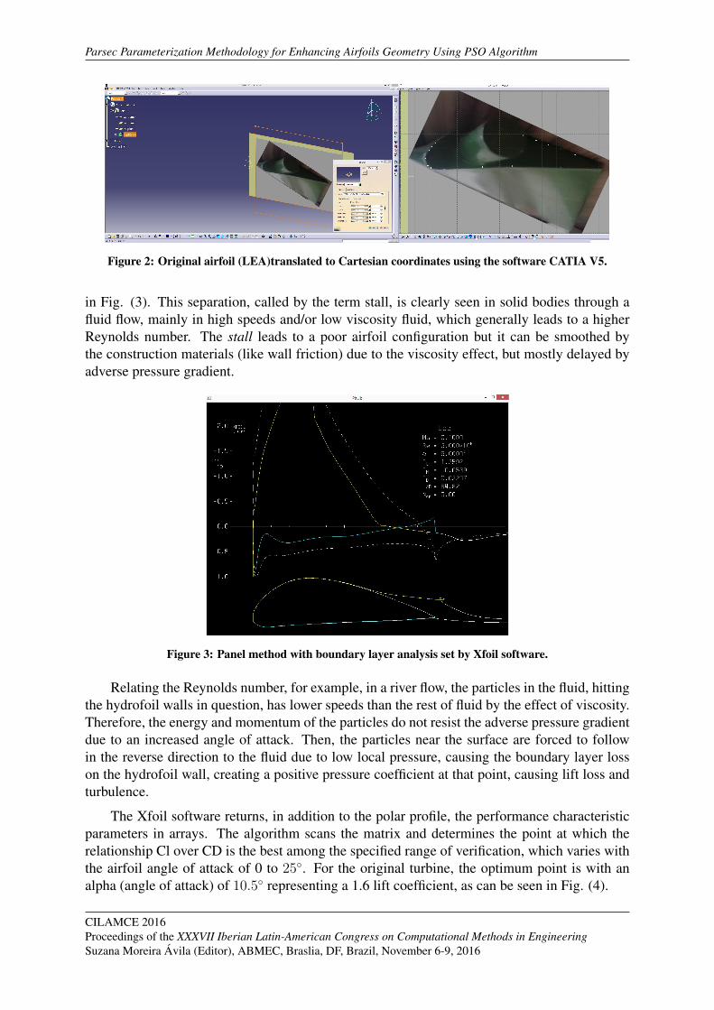
The Panel Method used in Xfoil software, have well-defined inputs that dictate the projectexecution. One of those entries is based on polar coordinates of the airfoil to be studied. Inorder to do so, the Cartesian coordinates were found by using the Shape Design tool of CATIAV5 software platform as can be seen on Fig. (2).
After the Cartesian coordinates is obtained, the process starts to get the parameter basesand to analyse them in each iteration to determine how the aerodynamic airfoil meets certainrequirement. Xfoil allows to vary different parameters according to the operator’s will on aparticular aspect of evaluation. This means that can be set in the Matlab code the evaluationprinciple, like attack angle, lift coefficient, drag coefficient and so on.
It can be noticed from Fig. (4), the boundary layer shift when it reaches an angle of attack of16◦ represented by the sudden decay of the supportative curve and the boundary layer (yellow)
CILAMCE 2016Proceedings of the XXXVII Iberian Latin-American Congress on Computational Methods in Engineering
Suzana Moreira Avila (Editor), ABMEC, Braslia, DF, Brazil, November 6-9, 2016
Parsec Parameterization Methodology for Enhancing Airfoils Geometry Using PSO Algorithm
Figure 2: Original airfoil (LEA)translated to Cartesian coordinates using the software CATIA V5.
in Fig. (3). This separation, called by the term stall, is clearly seen in solid bodies through afluid flow, mainly in high speeds and/or low viscosity fluid, which generally leads to a higherReynolds number. The stall leads to a poor airfoil configuration but it can be smoothed bythe construction materials (like wall friction) due to the viscosity effect, but mostly delayed byadverse pressure gradient.
Figure 3: Panel method with boundary layer analysis set by Xfoil software.
Relating the Reynolds number, for example, in a river flow, the particles in the fluid, hittingthe hydrofoil walls in question, has lower speeds than the rest of fluid by the effect of viscosity.Therefore, the energy and momentum of the particles do not resist the adverse pressure gradientdue to an increased angle of attack. Then, the particles near the surface are forced to followin the reverse direction to the fluid due to low local pressure, causing the boundary layer losson the hydrofoil wall, creating a positive pressure coefficient at that point, causing lift loss andturbulence.
The Xfoil software returns, in addition to the polar profile, the performance characteristicparameters in arrays. The algorithm scans the matrix and determines the point at which therelationship Cl over CD is the best among the specified range of verification, which varies withthe airfoil angle of attack of 0 to 25◦. For the original turbine, the optimum point is with analpha (angle of attack) of 10.5◦ representing a 1.6 lift coefficient, as can be seen in Fig. (4).
CILAMCE 2016Proceedings of the XXXVII Iberian Latin-American Congress on Computational Methods in EngineeringSuzana Moreira Avila (Editor), ABMEC, Braslia, DF, Brazil, November 6-9, 2016

Rafael Alves, Luciano Goncalves, Josiane do S. Aguiar, Antonio C. Brasil
Figure 4: Original airfoil representation for Cl and the range 0◦ to 25◦ of attack angle, as well as theoptimum point for Cl/CD.
Figure (5) represents the relation between the PARSEC parameterization and the originalairfoil. The representation by the eleven parameters of that method is highly effective to airfoilsfrom the NACA family, with differences between the geometries of only 3 basis functions.However, the airfoil study has a very peculiar profile, approaching the Goettigen German family,with a very sharp thickness near the aerodynamic center of the blade, which makes the exactconstruction of the parameterization by this method, difficult. Therefore, it can be noticed adisturb in the profile of the leading edge, but despite some variations, tolerance thickness errorin airfoil in a wind tunnel reaches 0.1% is satisfied (Kulfan, 2006). This oscillating feature iscommon in minimizing functions by least-squares.
Figure 5: Geometric representation of original (red) and parameterized hydrofoil (blue).
Finally, the first step, the four main representations of the original airfoil characteristics canbe seen in Fig. (6).
4.1 Optimization results
The iterative method returns a sample map which contains the convergence numbers of theoptimization method. The objective function is peculiar to the purpose of the algorithm, there-fore varies according to the operator desire. In this study, the objective function was defined to
CILAMCE 2016Proceedings of the XXXVII Iberian Latin-American Congress on Computational Methods in Engineering
Suzana Moreira Avila (Editor), ABMEC, Braslia, DF, Brazil, November 6-9, 2016

Parsec Parameterization Methodology for Enhancing Airfoils Geometry Using PSO Algorithm
Figure 6: The four main airfoil characteristics from the original hydrofoil given a range of 25 points of AoA.
maximize the ratio CL / CD, as discussed in the optimization session. The optimization endsafter 30 iterations without achieving any improvement in the relationship. To optimize the air-foil in question, 157 iterations, as shown in Fig. (7), with a sample space of 25 points werenecessary, which means 25 airfoils at each iteration. Thus, 4710 functions are evaluated whatdenote 9420 different airfoils forms evaluated by the algorithm as the Xfoil calls them 2 timesfor better accuracy.
Figure 7: Sample map of iteration numbers.
CILAMCE 2016Proceedings of the XXXVII Iberian Latin-American Congress on Computational Methods in EngineeringSuzana Moreira Avila (Editor), ABMEC, Braslia, DF, Brazil, November 6-9, 2016

Rafael Alves, Luciano Goncalves, Josiane do S. Aguiar, Antonio C. Brasil
Following the optimization sequence, the iterative process is represented in Fig. (8). Eachimage represents a different airfoil model. Basically, the base profile built by PARSEC parame-ter is modified in its parameters to generate new profiles. These profiles, then, pass through theoptimization process, and the basis functions that describe each is configured to converge intothe most appropriate purpose airfoil. Note that there is a certain regularity in the constructionof profiles after the 40◦ iteration, slightly varying the profile.
Figure 8: Iteration process of randomizing new airfoils from a given original airfoil (seed function).
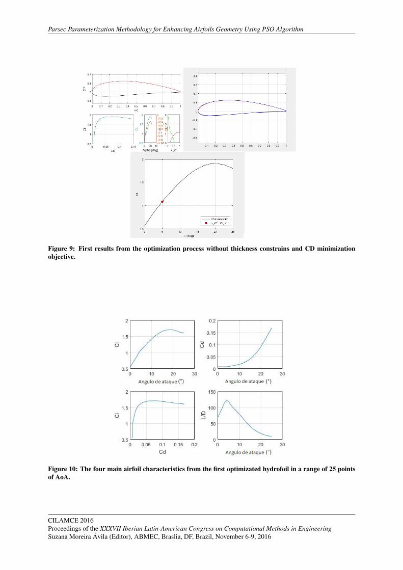
If the operator, set the optimization for the drag coefficient, the iterations converge to aminimum thickness, as can be seen from Fig. (9). In this study, the algorithm and generatingairfoils trying to find a balance between CD and CL.
The first series of tests returned the airfoil of Fig. (9). It is noted in the figure that theresults were satisfactory for both purpose specified and the optimum range. Compared withthe original airfoil, there was a gain of more than 80 units in the ratio CL / CD, reaching 126u. against 43 u. from the G2 turbine profile. However, the optimum angle of attack for thisremained at 10.5◦, while the optimized profile decreased to 5◦. It can be seen from Tab. (1),both results, original profile and optimized one.
Table 1: Cl/Cd comparison between original and optimized airfoil in each optimum angle.
Angle of Attack (◦) original Airfoil (u) Optimized Airfoil (u)
10.5 43 77
5 41 126
CILAMCE 2016Proceedings of the XXXVII Iberian Latin-American Congress on Computational Methods in Engineering
Suzana Moreira Avila (Editor), ABMEC, Braslia, DF, Brazil, November 6-9, 2016
Parsec Parameterization Methodology for Enhancing Airfoils Geometry Using PSO Algorithm
Figure 9: First results from the optimization process without thickness constrains and CD minimizationobjective.
Figure 10: The four main airfoil characteristics from the first optimizated hydrofoil in a range of 25 pointsof AoA.
CILAMCE 2016Proceedings of the XXXVII Iberian Latin-American Congress on Computational Methods in EngineeringSuzana Moreira Avila (Editor), ABMEC, Braslia, DF, Brazil, November 6-9, 2016
Rafael Alves, Luciano Goncalves, Josiane do S. Aguiar, Antonio C. Brasil
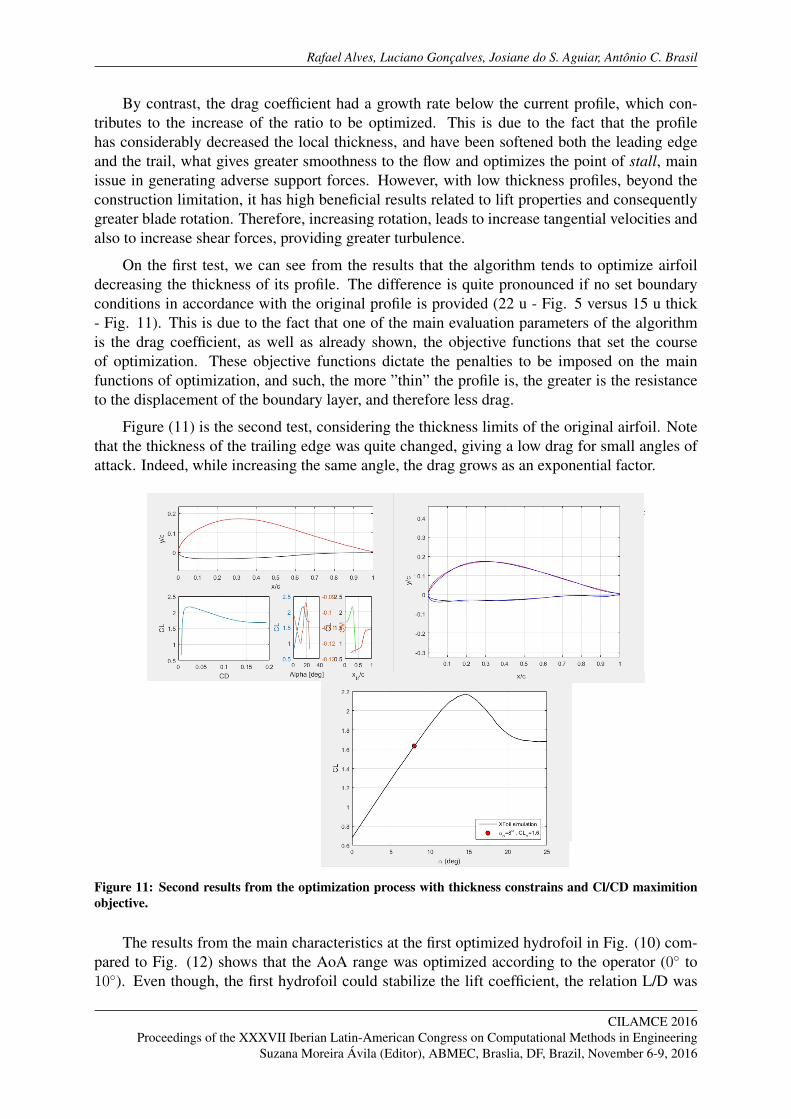
By contrast, the drag coefficient had a growth rate below the current profile, which con-tributes to the increase of the ratio to be optimized. This is due to the fact that the profilehas considerably decreased the local thickness, and have been softened both the leading edgeand the trail, what gives greater smoothness to the flow and optimizes the point of stall, mainissue in generating adverse support forces. However, with low thickness profiles, beyond theconstruction limitation, it has high beneficial results related to lift properties and consequentlygreater blade rotation. Therefore, increasing rotation, leads to increase tangential velocities andalso to increase shear forces, providing greater turbulence.
On the first test, we can see from the results that the algorithm tends to optimize airfoildecreasing the thickness of its profile. The difference is quite pronounced if no set boundaryconditions in accordance with the original profile is provided (22 u - Fig. 5 versus 15 u thick- Fig. 11). This is due to the fact that one of the main evaluation parameters of the algorithmis the drag coefficient, as well as already shown, the objective functions that set the courseof optimization. These objective functions dictate the penalties to be imposed on the mainfunctions of optimization, and such, the more ”thin” the profile is, the greater is the resistanceto the displacement of the boundary layer, and therefore less drag.
Figure (11) is the second test, considering the thickness limits of the original airfoil. Notethat the thickness of the trailing edge was quite changed, giving a low drag for small angles ofattack. Indeed, while increasing the same angle, the drag grows as an exponential factor.
Figure 11: Second results from the optimization process with thickness constrains and Cl/CD maximitionobjective.
The results from the main characteristics at the first optimized hydrofoil in Fig. (10) com-pared to Fig. (12) shows that the AoA range was optimized according to the operator (0◦ to10◦). Even though, the first hydrofoil could stabilize the lift coefficient, the relation L/D was
CILAMCE 2016Proceedings of the XXXVII Iberian Latin-American Congress on Computational Methods in Engineering
Suzana Moreira Avila (Editor), ABMEC, Braslia, DF, Brazil, November 6-9, 2016

Parsec Parameterization Methodology for Enhancing Airfoils Geometry Using PSO Algorithm
stabilized by the second one. It can be seen in the fourth graphic.
Figure 12: The four main airfoil characteristics from the second optimizated hydrofoil in a range of 25points of AoA.
Figure (12) translates the main characteristics of the second airfoil optimized. In the al-gorithm, it can establish which parameters and which optimization range the airfoil could besubjected. This study, it was defined the angle (0◦, 10◦), which means, the iterations will fo-cus on the parameters of that given optimization range. It is observed that after a limit of 10◦
parameters begin to decrease, particularly the L/D ratio, which shows the algorithm efficiencyand fidelity to track the operator sets up. Note that the drag coefficient increases exponentiallyafter the range, confirming the optimization of the statement within the set values.
The generation of these optimal parameters has been expended 4 hours and 13 minutes.This value changes depending on the complexity of the airfoil and the objective function. Asstated, the main goal of this optimization was the maximization of the ratio CL/CD by the PSOoptimization algorithm, so the whole amostral space was set to pursue the best value for thespecified aerodynamic property.
The entire process took place in an operational system governed by Windows 8 platform,with Matlab 2015 and Xfoil 6.9 software. The hardware is governed by an Intel i7 processor, 4GB of RAM.
Figure 13: Parsec parameters and optimum point configuration for the last optimized airfoil.
5 CONCLUSION
The use of computational process, as an important tool in understanding the physicalphenomena, is something already proven. Furthermore, it is concluded that the optimization
CILAMCE 2016Proceedings of the XXXVII Iberian Latin-American Congress on Computational Methods in EngineeringSuzana Moreira Avila (Editor), ABMEC, Braslia, DF, Brazil, November 6-9, 2016

Rafael Alves, Luciano Goncalves, Josiane do S. Aguiar, Antonio C. Brasil
methodology and airfoil analysis used in this paper were satisfactory for the quality of the re-sults generated, such as by the reasonable computational burden. The algorithm proved to bepowerful in certifying development issues and aerodynamic designs evaluation.
The code deployment, as well as the interaction between its different factors has its dif-ficulties, because dealing with computer programming routines with many iterations requirecaution, especially because of error propagation. However, it was found that a division of MAT-LAB functions could minimize this problem because each one validated its goals before solvingthe problem.
Regarding the parameterization, the PARSEC polynomials proved to be efficient in theairfoil description as a parameter generator, though, reducing them, some errors of the firstderivative function can still be seen. The 11 parameters that describe the airfoil cover a widerange of families, although in some cases, the error is accentuated more than others. Moreover,the representation has a simple formula to be implemented which makes the method one wayof testing simple optimization problems.
The Bspline parameterization is concise for cases with specific solutions, because it usescontrol points to represent the geometry curves. Furthermore, they can be randomized fromParsec basis in order to generate other airfoils with a structural basis similar to the original one.The fact of using these two parameterizations was exactly that, because the airfoils generationcapacity by an iterative process is more flexible with Bspline. It is due to the geometry, whichis not defined with specific physical characteristics, facilitating the random process of creatingnew shape designs in the optimization process. In addition, the operator can have greater controland flexibility on the airfoil surface by modifying the polynomial degree, and the number ofcontrol points, non-existent in Parsec parameterization.
The PARSEC and BSPLINE integration helped in the optimization process because thePSO algorithm uses randomized airfoil database to describe the search process for the optimalairfoil. However, it was found that there is a problem in the iterative process, because thebad airfoil designs were not discarded, as in the genetic algorithms. They have been stored inthe internal memory, and sometimes the algorithm brought them up again to be tested if therewere not a significant ”punishment” quad on them. For this reason, the first iterations weretoo slow to be completed. On the other hand, this problem can be partially solved by the useof a geometric viability control of the airfoils, avoiding unfeasible profiles, and reducing thecomputational waste.
Finally, the results were satisfactory for the purpose of this work. For the original airfoil,there was a gain of more than 80 units in the ratio Cl / Cd, reaching 126 u. versus 43 u. ofthe G2 turbine profile. Besides that, the lift coefficient remained relatively constant 1.56 u to1.63 u. Moreover, the optimum angle of attack decreased from 10.5◦ to 8◦, causing constructivelimitations, but is consistent with the range set by the operator used for the optimization, from0◦ to 10◦.
CILAMCE 2016Proceedings of the XXXVII Iberian Latin-American Congress on Computational Methods in Engineering
Suzana Moreira Avila (Editor), ABMEC, Braslia, DF, Brazil, November 6-9, 2016

Parsec Parameterization Methodology for Enhancing Airfoils Geometry Using PSO Algorithm
————————————————————————–
ACKNOWLEDGEMENTS
We would like to thank Clovis Campos for sharing his knowledge, as well as the universityof Brasılia, in the name of Extension Department (DEX), for the support given.
Also, the authors gratefully acknowledge the support given by the Master students from theMechanical Department which have been helping the algorithm implementation.
Finally, to all those who has been helping directly and indirectly this work.
REFERENCES
CONSENTINO GARY B HOLST, T. L. Numerical optimization design of advanced transonicwing configuration. Jornal of Aircraft, v. 23, n. 3, p. 192?199, 1986..
DRELA, M. Xfoil: An analysis and design system for low reynolds number airfoils. In: LowReynolds number aerodynamics. [S.l.]: Springer, 1989. p. 1?12.
ELS, R. H. V. et al. Hydrokinetic propeller type turbine for the electrification of isolated house-holders or community and social end-users. In: 17 Congresso de Engenharia Mecnica. [S.l.:s.n.], 2003.
GRANT, I. Basic concepts in turbomachinery. In: Ventus Publishing ApS. [S.l.: s.n.], 2009. v.1, p. 1?144. ISBN 978-87-7681-435-9.
HU, XIAOHUI PSO: Tutorial. 2006. Available in: <http://www.swarmintelligence.org/tutorials.php>.
KULFAN, B. M.; BUSSOLETTI, J. E. et al. Fundamental parametric geometry representationsfor aircraft component shapes. In: Machine Learning: ECML-93. [S.l.: s.n.], 2006.
Li, Wu and Padula Sharon, 2004 ”Using Resolution Design Spaces for Aerodynamic ShapeOptimization Under Ucertainty”,NASA /TB-2004-213003.
SOBIECZY, H. Parametric airfoils and wings. In: Recent Development of Aerodynamic DesignMethodologies. [S.l.]: Springer, 1998.
SHOENBERG, I. J. Contributions to the problem of approximation of equidistant data by ana-lytic functions. In: IJ Schoenberg Selected Papers. [S.l.]: Springer, 1988. p. 3?57.
CILAMCE 2016Proceedings of the XXXVII Iberian Latin-American Congress on Computational Methods in EngineeringSuzana Moreira Avila (Editor), ABMEC, Braslia, DF, Brazil, November 6-9, 2016