parametric investigation of a large xx(x):1–13 the author ... · this study aims at the...
TRANSCRIPT

Parametric investigation of a largemarine two-stroke dual fuel HPDI engineby using CFD
Journal TitleXX(X):1–13c©The Author(s) 2019
Reprints and permission:sagepub.co.uk/journalsPermissions.navDOI: 10.1177/ToBeAssignedwww.sagepub.com/
SAGE
Renyou Yang1 , Gerasimos Theotokatos2 and Dracos Vassalos2
AbstractThis study aims at the parametric investigation of the gas injection system settings of a large marine two-stroke dualfuel engine by using a developed and customized CFD method in the ANSYS Fluent software. The investigated engineinjection system parameters include the gas injection timing, the gas injection duration, the gas injector lateral angle,and the gas injector holes number. Based on the comparison of the predicted performance parameters for the closed-cycle processes, the results indicate that the gas injector lateral angle is the most significant parameter that affects theengine power as well as the NO and CO2 emissions. For satisfying the contradictory objectives of retaining the enginepower and reducing the NO and CO2 emissions, appropriate design settings for the gas injection are recommended forthe investigated engine operation in the gas mode at 75% load.
KeywordsMarine two-stroke dual fuel engine, High pressure direct gas injection, Gas injection parameters, Parametricinvestigation, CFD analysis
Introduction
Natural gas, which primarily consists of methane up to95%, is regarded as a promising alternative greener fuelfor marine engines and ships applications due to theadvance and availability of the marine duel fuel engines.It has been proved that the natural gas can contributeto the considerable reduction of green-house and non-greenhouse emissions from ship operations, thus reducingthe shipping industry environmental footprint. The naturalgas combustion characteristics are governed by the methaneproperties, such as the high octane number (ON). Highoctane number implies a relatively highly auto-ignitiontemperature, and therefore, renders the natural gas a suitablefuel for high compression ratio engines, which employpilot diesel fuel for providing the required ignition energyto enable combustion. The pilot fuel is considered as theignition kernel in this type of compression ignition (CI)engines.
For the four-stroke dual fuel engines, a number ofinvestigations related to the fuels (pilot and gas) injectionsettings were conducted. Larson1 and Imhof et al.2
experimentally quantified the effects of the relative injectiontiming (RIT) between the pilot and gas fuels injection startson the pollutant emissions. Lee and Montgomery3 performeda numerical analysis demonstrating that a small RIT couldcause the increase of the nitrogen oxides (NOx) emissions,whilst not considerably influencing the engine indicatedwork. In addition, other critical injection parameters, suchas the pilot and gas fuels injection timings 1,4−6, thefuels injection profile7, the fuels injection direction3,7,and the injectors holes number3, were investigated eitherexperimentally or by using computational fluid dynamics(CFD) methods.
For the two-stroke marine engines, which have beenwidely used for the merchant ocean-going ships propulsion,two different dual fuel types, namely the premixedcombustion engine and the direct injection engine, havebeen developed by the marine engine manufacturers. In theformer, the natural gas is injected at the mid-stroke cylinderposition, which subsequently mixes with the scavenge airduring the compression stroke8. In the latter, the naturalgas is compressed to a high pressure (around 30 MPa)and directly injected into the engine combustion chamberthrough the gas injectors. In subsequence, the formedmixture of natural gas and air is ignited by using the pilotfuel (injected earlier) ; the combustion is targeted to startclose to the cylinder top dead center (TDC)9. Owing tothe specific combustion characteristics, the knocking andmisfiring instabilities can be avoided in the high pressuredirect injection (HPDI) dual fuel engines, whereas thecarbon dioxide (CO2), nitrogen oxides (NOx), sulphuroxides (SOx) and particulate matter (PM) emissions can beconsiderably reduced in comparison with the diesel modeengine operation10. According to the engine manufacturer9,a marine two-stroke dual fuel HPDI engine can operate inthe diesel mode (burning diesel fuel oil) or in the gas mode;in the latter, the engine can operate with minimum pilot oil(employing a minimum amount of pilot diesel fuel to startthe combustion of the gas fuel) or at a specified dual fuel
1Peng Cheng Laboratory, Shenzhen, China2Maritime Safety Research Centre, Department of Naval Architecture,Ocean & Marine Engineering, University of Strathclyde, Glasgow, UK
Corresponding author:Renyou Yang, Peng Cheng Laboratory, 2 Xingke First Street, NanshanDistrict, Shenzhen, Guangdong, 518000, China.Email: [email protected]
Prepared using sagej.cls [Version: 2017/01/17 v1.20]

2 Journal Title XX(X)
operation (burning any mixture percentage of diesel fuel andgas fuel).
Experimental studies for investigating the in-cylinderprocesses in marine engines (of the diesel and dual fueltypes) are limited as is extremely challenging to measurethe in-cylinder performance parameters (apart from thecylinder pressure) for characterising and analysing thefuel injection, combustion and scavenging processes inthese engines. On the other hand, the CFD analysis hasbeen extensively employed for investigating the in-cylinderprocesses in internal combustion engines due to its advantageon capturing the involved complicated physics and thusestimating the spacial-temporal variations of the in-cylinderperformance and emissions parameters. However, this is thefirst study that investigates the injection and combustionprocesses in a large marine two-stroke dual fuel engine byusing CFD analysis.
The present study focuses on the parametric investigationof a large marine two-stroke dual fuel engine operationat 75% load by using the developed CFD models11. Theinvestigated dual fuel injection parameters include the gasinjection timing, the gas fuel injection duration, the lateralangle of the gas fuel nozzle and the gas injectors holesnumber. The effects of these parameters on the engineindicated work and emissions are identified and discussed,whereas the recommendations for the optimal design settingsof the gas injection parameters are provided. It must be notedthat the gas mode operation with the minimum pilot fueloperation is investigated in this study, denoted as gas modein the following sections.
CFD model
In this study, one cylinder of the large marine two-strokeHPDI dual fuel engine S60ME-GI12 is investigated byusing CFD analysis. The natural gas is directly injectedinto the engine combustion chamber close to the top deathcenter (TDC) with a high-pressure ratio (considering thepressure upstream the gas nozzle and the pressure of enginecombustion chamber). Due to the high octane number for thenatural gas, the pilot liquid fuel is required to be injected, inorder to ignite the natural gas.
The closed-cycle operating processes of the investigatedengine are simulated by employing the CFD softwareANSYS Fluent13. The SST k-ω turbulence model14 isadopted to close the Reynolds-averaged Navier–Stokes(RANS) equations, whereas the Peng–Robinson gas stateequation15 is employed as the working conditions ofthe mixture in the engine combustion chamber reach thesupercritical state. The dynamic mesh method is also used,due to the piston reciprocating motion, as well as theadjustable time steps in the cycle part with the fuels (pilotand gas) injection and combustion processes.
With regards to the pilot fuel injection, the atomizer modelwith the cone-shaped region in the CFD software ANSYSFluent13 is used to simulate the initial injection process. Theprofiles of the pilot fuel injection velocity and the associatedinjection rate are estimated by using the Bernoulli equation.The SSD model16 is employed to simulate the pilot fuelbreakup process.
As the high-pressure gas is injected into the enginecombustion chamber, the underexpanded flow downstreamthe gas nozzle and the expansion fan is expected to movetowards the high-pressure side inside the gas nozzle, whichsignificantly affects the gas injection and the entrainmentwith the engine combustion chamber mixture17,18. Herein,the pseudo-diameter concept17 and the 1-D shock tubetheory are employed to evaluate such effects, as proposedin Hajialimohammadi et al.18. The normal gas injectionvelocity and the pseudo diameter are calculated by thefollowing equations:
Ug = (P6 − P∝)√
2ρ∝[(γ∝+1)P6+(γ∝−1)P∝]
=2√γgRmgTg
γg−1
[1− (P6
Pg)(γg−1)/2γg
] (1)
dps = dn
√P6
P∝(2)
Chocked flow conditions are expected in the gas nozzlesdue to the high-pressure gas injection. Therefore, thecorresponding injected gas mass flow rate and density arecalculated by the following equations:
mg =14πd
2nρg
√γgRmgTg(
2γg+1 )
2γg−12(γg−1) (3)
ρps = ρgP∝P6
√γgRmgTg
Ug( 2γg+1 )
2γg−12(γg−1) (4)
The developing conserved-equation sources approach11 isemployed to simulate the high-pressure gas injection intothe engine combustion chamber. The source terms of themass, momentum, enthalpy and mixture fraction governingequations, which are used to represent the gas injectioninto the engine combustion chamber, are described by thefollowing equations, respectively:
SU =∑
mg/δVg (5)
~FU =∑
Ugmg~ng/δVg(6) (6)
Sh =∑
(
∫ Tg
Tref
CPgdT + h0g)mg/δVg (7)
SZ =∑
mg/δVg (8)
The source terms for the turbulent kinetic energy and itsdissipation rate are estimated by the following equations, asproposed by Choi et al.19.
Sk = 1.5(U′
g)2ρps/dt (9)
Sε = 0.5[1.5(U′
g)2]1.5ρps/(dndt) (10)
The employed fuels (pilot diesel and gas) combustionmodels are based on the steady diffusion flamelet model20.The pilot fuel combustion process is firstly calculated,in which the combustion kernel parameters including thelocations, the diameter and the temperature distributionsagainst the crank angle are estimated. Subsequently, theenergy equation source attributed to the pilot fuel combustion
Prepared using sagej.cls

Yang,Theotokatos and Vassalos 3
are estimated by using the following equation:
Sig =∑k
Yk[
∫ Tir
Tlocal
CP,kdT ] (11)
The high-pressure gas is injected into the enginecombustion chamber, where it subsequently ignites by thepilot fuel combustion kernel; this is modelled by introducingthe source term Sig in the total enthalpy equation. Theassociated skeletal chemical kinetics mechanism of thenatural gas (methane) is derived from Bilger and Starner21.The details of the employed fuels non-premixed combustionmodels are described in Yang11.
Validation of the diffusion combustionmodelsThe comprehensive CFD validation of the injection andcombustion models for the investigated engine operating inthe gas mode was conducted by Yang11, including the pilot(liquid) fuel injection model, the high-pressure gas injectionmodel, the dual fuel combustion model and the comparisonof the derived engine performance with the respective engineoperation at the diesel operating mode.
In this section, the experimentally measured parameters ina rapid compression expansion machine (RCEM) reported inImhof et al.2 are used to validate the developed pilot and gasfuels injection and combustion models. In addition, the theperformance and emission parameters for the dual fuel (DF)and the diesel operations of the RCEM are calculated andcompared with the respective experimental measurementsfrom Imhof et al.2.
Figure 1 depicts the derived heat release rates (HRRs)from the CFD model calculations and the experimentallymeasured parameters. Based on these results, it can bededuced that the developed models can adequately predictthe non-premixed combustion processes for the diesel andthe DF modes. The nitrogen monoxide (NO) emissions in thedeveloped models are calculated by employing the extendedZeldovich mechanism according to the recommendedreaction rates by Hanson and Salimian22. By comparing thederived results with the measured NO emissions as shownin Table 1, it can be inferred that the change of the NOemissions between the DF mode and the diesel mode aresufficiently evaluated by the CFD model, despite of thenotable discrepancy up to 38% in the absolute NO fractionvalues. Similar trends were reported in Schwerdt23 and Taoet al.24, in which the errors between the measured and thecalculated NO emissions were estimated up to 50% or more.
The HRRs calculated by using the CFD model resultsfor three different cases of the pilot fuel injection timing(early, normal, late) along with the respective experimentallyobtained HRRs by Imhof et al.2 are shown in Figure 2. Bycomparing the CFD results with the experimental results(Figure 2 and Table 1), it can be inferred that the calculatedHRRs as well as the NO emissions variation are of adequateaccuracy for the early and normal pilot injection cases.
In the case of the late pilot injection timing, a considerableincrease of the peak HRR value is observed in theexperimental results. When the pilot injection and the maingas injection timings are close, the liquid fuel ignition is
Figure 1. HRRs calculated by the developed CFD models andthe experiments conducted by Imhof et al.2 for the diesel anddual fuel operation in the RCEM chamber.
Figure 2. Comparison of HRRs between the experiment (takenfrom Imhof et al.2 and the CFD model for three different pilotfuel injection timings in the RCEM chamber.
delayed due to the high dissipation rate and the lack ofoxygen content within the ignition kernel, caused by thehigh-speed gas injection and the high concentration of gasfuel. The pilot fuel continuously accumulates, followed bythe extremely rapid combustion in the rich fuel mixture. Therespective experimental HRR shown in Figure 2 depicts thatthe ignition delay of the pilot fuel is apparently prolongedand a high peak of the HRR is obtained. Due to the separatemodelling of the pilot fuel and the main gas non-premixedcombustion processes, such strong interaction between themain gas and pilot fuels cannot be captured by the employedCFD models.
Table 1. Comparison of NO emissions [in ppm] for the dual fueland diesel modes in RCEM chamber.
Modes Developed CFD models Experiments 2
Diesel 648 531DF 244 346-393Early(DF) 111 223Normal(DF) 105 216Late(DF) 104 260
Parametric InvestigationAiming to obtain the recommended settings of the gas fuelinjection for the investigated marine two-stroke dual fuelHPDI engine operating in the gas mode (with minimum pilotfuel according to the engine manufacturer9) at the 75% load,
Prepared using sagej.cls

4 Journal Title XX(X)
Figure 3. Engine cylinder sketch illustrating the gas injectorlateral angle (βi), the gas injector inclination angle (αi), and thegas injector location (point I); coordinate z corresponds to theengine cylinder vertical axis.
the parametric investigation of the closed-cycle operation isconducted numerically by using the developed CFD models.The characteristics of the investigated engine12 are listed inTable 2. The investigated gas injection parameters includethe gas injection timing, the gas injection duration, the lateralangle of the gas nozzle (βi, as shown in Figure 3) and the gasinjectors holes number.
Table 2. MAN Diesel & Turbo engine 5S60ME-GIcharacteristics9,12.
Parameters Symbol Unit Value
Stroke S m 2.4Bore B m 0.6Crank Radius R m 1.2Engine Speed (75% Load) N r/min 91.3Engine Power(75% Load) PB kW 7875
Effects of the gas injection timingTable 3 illustrates the pilot fuel and gas fuel injectiontiming and duration for three investigated cases (DF1-DF3).For the first investigated case (DF1), the injection settingswere derived from the pilot fuel injection pressure and thegas injection pressure curves reported by Kjemtrup10. Theinclination angle of the gas injector was set to 15, in orderto avoid the gas accumulation close to the cylinder head25.
The other two cases (DF2 and DF3) consider an earlier gasignition timing at 5.67CA and 0CA, respectively.
Table 3. Investigated cases DF1-DF3 settings with different gasfuel injection timings.
Case Timing(CAATDC)
Duration(CA)
HolesNumber(-)
αi
()βi()
DF1 13.81 17.32 1 15 0DF2 5.67 17.32 1 15 0DF3 0 17.32 1 15 0
Figure 4 results demonstrate that advancing the gasinjection start to the top death center (TDC) (investigatedcase DF3) can substantially increase the in-cylinder pressure.The cylinder close-cycle indicated mean effective pressure(PEC) (calculated from -7CA ATDC to 110CA ATDC)for the DF2 case increases by 14% compared to that of theDF1 case. This is due to the improvement of the gas fuelcombustion process, leading to the significant reduction ofthe incomplete combustion products (carbon monoxide (CO)and unburned hydrocarbons (HC) emissions) as shown inTable 4.
The derived heat release rates (HRRs)26 for the threeinvestigated cases are presented in Figure 5. Four peaksare observed in the HRRs variations; the three of them areassociated with the pilot and the gas fuel combustion. Thelast peak observed around 40CA ATDC is attributed to thenumerical issues caused by the change of the time step forthe decrease of the simulation run computational time. Thefirst valley of the HRR variation is apparently due to thecompletion of the pilot fuel combustion, whereas the secondvalley is attributed to the cold gas plumes impinging on theburning gas.
As expected, the improvement of the gas fuel combustionusually implies the higher in-cylinder combustion tempera-ture, which would lead to the increase of the NO emissions.However, the derived NO emissions for the DF2 case arefound to be slightly lower than that for the DF1 case. Basedon the comparison of the in-cylinder maximum temperaturevariations and the variations of the high-temperature volumeratio in temperature above 2000 K for the DF1 and DF2cases (depicted in Figures 6 and 7), it can be inferred thatthe greater NO emissions for DF1 is primarily attributed tothe late continuous gas fuel combustion.
Effects of the gas injection durationThree cases (DF4, DF5 and DF6) with the gas injection dura-tion varying from 11.24CA to 17.32CA are investigated aslisted in Table 5.
The results shown in Figure 8 and Table 5 demonstratethat shortening the gas injection duration increases the in-cylinder maximum pressure and the corresponding closed-cycle indicated mean effective pressure, as well as providesa higher pressure rise. This is attributed to the increase of theinjected gas mass flow rate and the resulted faster combustionprocess, due to the reduction of the gas injection duration.Table 6 also indicates that there is no notably change inthe intermediate species (CO and HC) produced by theincomplete combustion, which implies that the reduction of
Prepared using sagej.cls

Yang,Theotokatos and Vassalos 5
Figure 4. In-cylinder pressure variations for the investigatedcases DF1, DF2 and DF3 with different gas injection timings.
Figure 5. HRR variations for the investigated cases DF1, DF2and DF3 with different gas injection timings.
Figure 6. In-cylinder maximum temperature variations for theinvestigated cases DF1, DF2 and DF3 with different gasinjection timings.
Figure 7. In-cylinder high-temperature (above 2000 K) volumeratio variations for the investigated cases DF1, DF2 and DF3with different gas injection timings.
Table 4. Calculated engine performance and emissionsparameters for the DF1, DF2 and DF3 cases with different gasfuel injection timings.
Case PEC
(MPa)NOmassfraction(10−6)
COmassfraction(10−6)
HCmassfraction(10−6)
CO2
massfraction(10−6)
DF1 1.980 986 11526 304 54796DF2 2.056 839 10641 211 54557DF3 2.250 1109 5089 76 56251Note: Emissions evaluated at 110CA ATDC before the exhaustvalve open;
PEC =∫ 110CA−7CA
P dV
ΩS;
P : Cylinder pressure;V: Cylinder volume;ΩS : Cylinder displacement volume.
the gas injection duration and the resultant increase of the gasflow rate do not remarkably improve the gas fuel combustionquality and emissions.
Apparently, the greater cylinder pressure caused by thehigher availability of the prepared gas–air mixture leadsto a greater in-cylinder mean temperature and heat releaserate during the gas injection period, as shown in Figure 9.The considerable reduction of the released heat taking placeafter the early stage of gas fuel burning at around 6CA isattributed to the contact of the cold gas plumes with the flamesurface.
The three investigated cases (DF4, DF5 and DF6) almostexhibit the same NO emissions, as inferred from theresults presented in Table 6, where the maximum differencebetween the three cases is about 5% . The NO formationis associated with the high-temperature zone within theengine cylinder. The DF6 case with the shortest gas injectionduration exhibits the greater maximum temperature in thelate combustion phase around 40–50CA, as shown in Figure10. With respect to the volume occupied by the gas zone withthe temperature greater than 2000 K, only slightly changescan be observed in the results of Figure 11.
Table 5. Investigated cases DF4-DF6 settings with different gasfuel injection duration periods.
Case Timing(CAATDC)
Duration(CA)
HolesNumber(-)
αi
()βi()
DF4 0 17.32 1 15 0DF5 0 14.46 1 15 0DF6 0 11.24 1 15 0
Effects of the Single-Hole Gas Injector LateralAngleIn order to avoid the extended contact of the injected gasstream with the diffusion flame surface, three cases (DF6,DF7 and DF8) for the single-hole gas injector with thedifferent lateral angles are investigated, the parameters ofwhich are presented in Table 7.
From the in-cylinder pressure variations presented inFigure 12, it could be deduced that the change of the
Prepared using sagej.cls

6 Journal Title XX(X)
Figure 8. In-cylinder pressure variation for the investigatedcases DF4, DF5 and DF6 with different gas injection durationperiods.
Figure 9. HRR curves for the investigated cases DF4, DF5 andDF6 with different gas injection duration periods.
Figure 10. Maximum temperature variation for the investigatedcases DF4, DF5 and DF6 with different gas injection durationperiods.
Figure 11. High-temperature volume ratio in-cylinder greaterthan 2000 K for the investigated cases DF4, DF5 and DF6 withdifferent gas injection duration periods.
Table 6. Calculated engine performance and pollutantemissions for the DF4, DF5 and DF6 cases with different gasfuel injection duration periods.
Case PEC
(MPa)NOmassfraction(10−6)
COmassfraction(10−6)
HCmassfraction(10−6)
CO2
massfraction(10−6)
DF4 2.230 1008 5938 149 69026DF5 2.261 1059 5994 126 69541DF6 2.262 1046 6013 120 68402
gas injection direction significantly affects the mean in-cylinder pressure. In addition, the corresponding closed-cycle indicated mean effective pressure increases by 12%as the lateral angle of gas injector varies from 0 to -30 as shown in Table 8. The increase of the in-cylinderpressure is attributed to the improvement of the combustionquality. The HRR curves shown in Figure 13 demonstratethe improvement of the gaseous fuel combustion process, asgreater heat release rates were obtained for the investigatedcases with a larger gas injector lateral absolute angle.
From Table 8 results, it is deduced that the unburnedhydro-carbon (HC) emissions reduce as the gas injectorlateral angel absolute value increases. As expected, moreCO2 emissions and less intermediates are produced as thelateral angle of the gas nozzle changes to -30 in comparisonwith the cases with the smaller gas injector lateral angleabsolute values.
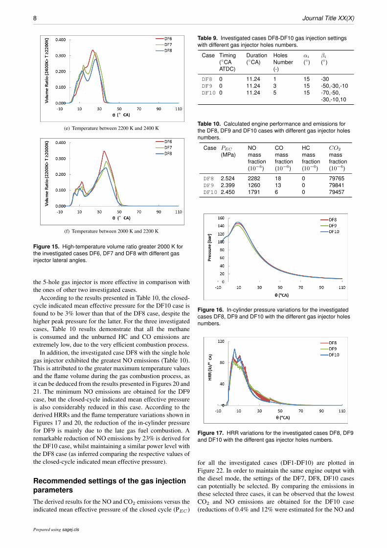
From Figure 14, it can be deduced that the period withthe maximum temperature around 2600 K is shortened inthe DF6 case, which is attributed to the reduction of theintermediates dwelling in the cylinder. However, the NOemissions substantially increase, as indicated in Table 8. Thisis owing to the fact that the combustion chamber volume withthe temperature greater than 2400 K significantly increases,as illustrated in Figure 15.
Table 7. Investigated cases DF6-DF8 gas injection settingswith different gas injector lateral angles.
Case Timing(CAATDC)
Duration(CA)
HolesNumber(-)
αi
()βi()
DF6 0 11.24 1 15 0DF7 0 11.24 1 15 -15DF8 0 11.24 1 15 -30
Table 8. Calculated engine performance and emissions for theDF6, DF7 and DF8 cases with different gas injector lateralangles.
Case PEC
(MPa)NOmassfraction(10−6)
COmassfraction(10−6)
HCmassfraction(10−6)
CO2
massfraction(10−6)
DF6 2.262 1046 6013 120 68402DF7 2.458 1864 1419 8 77596DF8 2.524 2282 18 0 79765
Prepared using sagej.cls

Yang,Theotokatos and Vassalos 7
Figure 12. In-cylinder pressure variation for the investigatedcases DF6, DF7 and DF8 with different gas injector lateralangles.
Figure 13. HRRs variations for the investigated cases DF6,DF7 and DF8 with different gas injector lateral angles.
Figure 14. Maximum temperature for the investigated casesDF6, DF7 and DF8 with different gas injector lateral angles.
Effects of the Gas Injector Holes NumberThree types of gas injectors with one, three and five holes areinvestigated (cases DF8, DF9 and DF10, respectively). Thelateral angle of the middle hole in each gas injector is -30,whereas the separation angle between holes is considered tobe 20. The gas injectors settings for the three investigatedcases are illustrated in Table 9.
The results presented in Figures 16 and 17 demonstratethat the relationship between the gas injector holes number,the HRRs and the in-cylinder pressure is not monotonous.The greatest heat release peak values caused by the fastestgas fuel burning rate (Figure 17) were obtained for theDF10 case with the largest number of gas injector holes.This resulted in the greatest in-cylinder maximum pressurevalues and the lowest in-cylinder pressure during the late
(a) Temperature greater than 2600 K
(b) Temperature between 2550 K and 2600 K
(c) Temperature between 2500 K and 2550 K
(d) Temperature between 2400 K and 2500 K
Figure 15. High-temperature volume ratio greater 2000 K forthe investigated cases DF6, DF7 and DF8 with different gasinjector lateral angles.
combustion process period as well as the fastest CO2
production (Figure 18). The results presented in Figure 19demonstrate that the mixing process for the DF10 case with
Prepared using sagej.cls
8 Journal Title XX(X)
(e) Temperature between 2200 K and 2400 K
(f) Temperature between 2000 K and 2200 K
Figure 15. High-temperature volume ratio greater 2000 K forthe investigated cases DF6, DF7 and DF8 with different gasinjector lateral angles.
the 5-hole gas injector is more effective in comparison withthe ones of other two investigated cases.
According to the results presented in Table 10, the closed-cycle indicated mean effective pressure for the DF10 case isfound to be 3% lower than that of the DF8 case, despite thehigher peak pressure for the latter. For the three investigatedcases, Table 10 results demonstrate that all the methaneis consumed and the unburned HC and CO emissions areextremely low, due to the very efficient combustion process.
In addition, the investigated case DF8 with the single holegas injector exhibited the greatest NO emissions (Table 10).This is attributed to the greater maximum temperature valuesand the flame volume during the gas combustion process, asit can be deduced from the results presented in Figures 20 and21. The minimum NO emissions are obtained for the DF9case, but the closed-cycle indicated mean effective pressureis also considerably reduced in this case. According to thederived HRRs and the flame temperature variations shown inFigures 17 and 20, the reduction of the in-cylinder pressurefor DF9 is mainly due to the late gas fuel combustion. Aremarkable reduction of NO emissions by 23% is derived forthe DF10 case, whilst maintaining a similar power level withthe DF8 case (as inferred comparing the respective values ofthe closed-cycle indicated mean effective pressure).
Recommended settings of the gas injectionparametersThe derived results for the NO and CO2 emissions versus theindicated mean effective pressure of the closed cycle (PEC)
Table 9. Investigated cases DF8-DF10 gas injection settingswith different gas injector holes numbers.
Case Timing(CAATDC)
Duration(CA)
HolesNumber(-)
αi
()βi()
DF8 0 11.24 1 15 -30DF9 0 11.24 3 15 -50,-30,-10DF10 0 11.24 5 15 -70,-50,
-30,-10,10
Table 10. Calculated engine performance and emissions forthe DF8, DF9 and DF10 cases with different gas injector holesnumbers.
Case PEC
(MPa)NOmassfraction(10−6)
COmassfraction(10−6)
HCmassfraction(10−6)
CO2
massfraction(10−6)
DF8 2.524 2282 18 0 79765DF9 2.399 1260 13 0 79841DF10 2.450 1791 6 0 79457
Figure 16. In-cylinder pressure variations for the investigatedcases DF8, DF9 and DF10 with the different gas injector holesnumbers.
Figure 17. HRR variations for the investigated cases DF8, DF9and DF10 with the different gas injector holes numbers.
for all the investigated cases (DF1-DF10) are plotted inFigure 22. In order to maintain the same engine output withthe diesel mode, the settings of the DF7, DF8, DF10 casescan potentially be selected. By comparing the emissions inthese selected three cases, it can be observed that the lowestCO2 and NO emissions are obtained for the DF10 case(reductions of 0.4% and 12% were estimated for the NO and
Prepared using sagej.cls

Yang,Theotokatos and Vassalos 9
Figure 18. Mass fraction of carbon dioxide for the investigatedcases DF8, DF9 and DF10 with the different gas injector holesnumbers.
CO2, respectively in comparison with the DF8 case). In thisrespect, the gas injection parameters of the DF10 case arerecommended for the investigated engine operation in the gasmode (with the minimum pilot fuel according to the enginemanufacturer9) at 75% load.
In order to compare the power output of the investigatedengine operating in the gas and diesel modes, the fullengine cycle of one engine cylinder was simulated at 75%load in both operating modes by employing the developedCFD model. To simulate the engine open cycle processes(which include the exhaust blowdown and the scavengingprocesses), the exhaust valve lift profile and the scavengingports opening/closing profile were provided as input. Thedeveloped CFD model in the ANSYS Fluent software13
was set up to automatically activate/deactivate the domainsrepresenting the exhaust port and the scavenge air box basedon the crank angle, as well as to adjust the simulation timestep accordingly.
The derived CFD model results for the in-cylinderpressure variation and the HRRs are presented in Figure23 and 24. The experimentally measure cylinder pressurediagram for the diesel mode operation taken from Jin27 isalso presented in Figure 23. It can be deduced from Figure23 results, that the CFD model predicted in-cylinder pressurevariation for the diesel mode operation almost coincideswith the respective experimentally measured one. For thediesel mode, the difference of the calculated full-cycleindicated mean effective pressure from the CFD results andthe measured values is within 0.1% (despite of the slightlyunderestimation by 1.8% of the in-cylinder maximumpressure in the case of the CFD model calculations). In thisrespect, it can be inferred that the CFD model results are ofadequate accuracy.
Based on the cylinder pressure variations for the gas andthe diesel modes shown in Figure 23, it can be inferredthat the difference in calculated full-cycle indicated meaneffective pressures for these two modes is lower than 0.1%. Therefore, it can be concluded that that the recommendedinjection settings employed for the gas operating mode at75% load render the investigated engine to retain the dieselmode power output (at the same load conditions).
The heat release rate (HRR) for the gas mode isremarkably different than that of the diesel mode, as shownin Figure 24. For the diesel operation, the valley between thetwo HRR peaks is attributed to the less fuel vapour retained
(a) Single-hole gas injector
(b) Three-hole gas injector
(c) Five-hole gas injector
Figure 19. The temperature contours on the stoichiometricsurface of the gas plumes at crank angle 10CA ATDC for theinvestigated cases DF8, DF9 and DF10 with different gasinjector holes number.
in the engine combustion chamber11. The HRR for the gasmode reaches its maximum value at 5.62CA ATDC; the
Prepared using sagej.cls

10 Journal Title XX(X)
Figure 20. In-cylinder maximum temperature variations for theinvestigated cases DF8, DF9 and DF10 with different gasinjector holes number.
(a) Temperature greater than 2600 K
(b) Temperature between 2550 K and 2600 K
(c) Temperature between 2500 K and 2550 K
Figure 21. High-temperature volume ratio greater 2000 K forthe investigated cases DF8, DF9 and DF10 with different gasinjector holes number.
(d) Temperature between 2400 K and 2500 K
(e) Temperature between 2200 K and 2400 K
(f) Temperature between 2000 K and 2200 K
Figure 21. High-temperature volume ratio greater 2000 K forthe investigated cases DF8, DF9 and DF10 with different gasinjector holes numbers.
gradual decrease of the HHR variation follows the peak valuepoint .
Table 11 indicates that the CO2 and NO emissions for thegas mode are lower of 21% and 31% respectively than theones estimated for the diesel mode. The HC emissions arealmost eliminated in both operation modes, which coincideswith the literature findings for the HPDI engine types(considerable NOx emissions and very low HC emissions).
ConclusionsThe parametric investigation of the large marine two-strokedual fuel engine of the high pressure direct injection (HPDI)type was conducted for the gas mode (with minimum pilot
Prepared using sagej.cls

Yang,Theotokatos and Vassalos 11
Table 11. Calculated emissions by the CFD model for engineoperation in the gas and diesel modes at 75% load.
OperatingMode
HC massfraction(10−6)
CO2 massfraction (% )
NO massfraction(10−6)
Gas mode 0.0 7.95 1820Dieselmode
0.0 9.96 2622
(a) NO emissions versus PEC
(b) CO2 emissions versus PEC
Figure 22. NO and CO2 emissions versus the closed-cycleindicated mean effective pressure (PEC ) for all the investigatedcases (DF1 to DF10) .
Figure 23. In-cylinder pressure variations in the complete cyclefor the investigated engine operation in the gas mode (denotedas Dual Fuel in the legend) and the diesel mode at 75% load.
fuel) operation at 75% load. One cylinder of the 5S60ME-GIengine was simulated by employing a CFD model developedin the ANSYS Fluent software, which utilises sub-models
Figure 24. HRR variations calculated by the CFD model for theinvestigated engine operation in the gas mode (denoted as DualFuel in the legend) and the diesel mode at 75% load.
and domains for representing both the closed-cycle and thefull-cycle processes. The following settings for the gas fuelinjection were investigated: the gas injection timing, thegas injection duration, the gas injector holes number, andthe gas injector direction. The recommended settings wereidentified by considering the close-cycle indicated meaneffective pressure, the heat release rates as well as the NOand CO2 emissions. The full-cycle was simulated for thecases of the gas operating mode with the recommendedsettings and the diesel operating mode, so that the engineperformance and emissions parameters are compared anddiscussed.
The main findings of this study are summarised as follows.
(i) The most sensitive parameter from the investigatedgas injection settings was found to be the gas injectorlateral angle. Changes of the gas injector lateralangle from 0 to -30 resulted in a considerableimprovement of the gaseous fuel combustion process;in specific, increased the closed-cycle indicated meaneffective pressure by 12% substantially increased theNO and CO2 emissions as well ad reduced the HCemissions.
(ii) For satisfying the contradictory objectives of retainingthe engine power and reducing the NO and CO2
emissions, the gas injection parameters of the DF10case were recommended for the investigated engineoperating in the the gas mode at 75% load.
(iii) The engine operation with the recommended injectionsettings in the gas mode at 75% load exhibited thesame power output with the diesel mode operation;however the carbon dioxide and the nitrogen monoxideemissions for the gas mode were found to be 21%and 31% lower than the ones of the diesel mode,respectively.
In conclusion, the developed CFD model as well as theresults of this study can remarkably beneficial for reducingthe effort required to optimise the engine settings in theother engine loads. The developed CFD method is expectedto be a useful tool and can be employed during the enginedesign phase as: (a) it provides advantages on investigatingthe engine cycle physical phenomena and capturing thecomplicated physics of the involved processes; (b) theengine performance and emissions strongly depend on theengine components design, the engine systems settings and
Prepared using sagej.cls

12 Journal Title XX(X)
the engine operating conditions; and (c) it is extremelychallenging and costly to directly acquire measurements(apart from the in-cylinder pressure) that can be employedfor characterising the engine in-cylinder processes.
The following areas are proposed for the futureinvestigation of the large marine two-stroke dual fuelengines:
(i) Optimisation of the gas injection parameters in otherengine loads with the objectives to retain the enginepower and reduce the NO and CO2 emissions.
(ii) Various gas fuels with different characteristics, theirskeletal chemical mechanisms as well as their effectson the engine combustion process.
(iii) Other fuels including bio-diesel, methanol, bio-gas, and synthetic fuel, as well as their chemicalmechanisms.
Acknowledgements
All the CFD simulations presented in the paper were carried outat the ARCHIE-WeSt supercomputers. The authors would like toappreciate the administrators to provide the adequate computationalresources to complete this investigation. The authors gratefullyacknowledge the financial support of the European Commissionthrough the research project JOULES (Website: http://www.joules-project.eu), which is jointly funded by the 7th
Framework Programme and the industry, for the work reportedin this article. The authors from MSRC greatly acknowledge thefunding from DNV GL AS and RCCL for the MSRC establishmentand operation. The opinions expressed herein are those of theauthors and should not be construed to reflect the views of EU, DNVGL AS and RCCL.
References
1. Larson CR. Injection study of a diesel engine fuelled withpilot-ignited, directly-injected natural gas. Master Thesis,University of British Columbia, Canada 2003.
2. Imhof D, Tsuru D, Tajima H and Takasaki K. High-pressurenatural gas injection (GI) marine engine research with arapid compression expansion machine. In: 27th CIMAC WorldCongress on Combustion Engines, Shanghai, China, 13-16May 2013.
3. Lee WG and Montgomery D. Numerical investigation ofthe performance of a high pressure direct injection (HPDI)natural gas engine. In: Proceedings of the ASME InternalCombustion Engine Division Fall Technical Conference,Volume 2: Instrumentation, Controls, and Hybrids; NumericalSimulation; Engine Design and Mechanical Development;Keynote Papers: V002T06A019, Columbus, IN, USA, October19-22, 2014.
4. Li M, Zhang Q, Li G and Shao S. Experimental investigation onperformance and heat release analysis of a pilot ignited directinjection natural gas engine. Energy 2015; 90: 1251-1260.
5. Zhang Q, Li M and Shao S. Combustion process and emissionsof a heavy-duty engine fueled with directly injected natural gasand pilot diesel. Applied Energy 2015; 157: 217–228.
6. Gao Y, et al. Numerical simulations of natural gas injectionpressure effects on a direct injected, pilot ignited, natural gasengine. Applied Mechanics and Materials 2014; 510: 179-184.
7. Wang Q, Shao C, Liu Q, Zhang Z and He Z. Effects of injectionrate on combustion and emissions of a pilot ignited directinjection natural gas engine. Journal of Mechanical Scienceand Technology 2017; 31(4): 1969-1978.
8. Duggal VK, Lyford-Pike EJ and Wright JF. Development ofthe high-pressure direct-injected, ultralow-NOx natural gasengine: final report. Report for National Renewable EnergyLaboratory (NREL). Report no. SR-540-35911, 2004. Golden,CO (US).
9. MAN B&W. MAN B&W S60ME-C8.5-GI-TII, projectguide - electronically controlled dual fuel two-strokeengines,https://marine.man-es.com/two-stroke/project-guides(2016, accessed 5 May 2016).
10. Kjemtrup N. Gas 2-stroke marine engine design and operation.In: Greek CIMAC Association Seminar, Athens, Greece, 22January 2015.
11. Yang R. CFD modelling and investigation of the marine dual-fuel two-stroke engine with gas high pressure direct admission.PhD Thesis, University of Strathclyde, UK, 2018.
12. MAN B&W. CEAS engine data report 5S60ME-C8.5-GI(methane) with high load tuning, http://marine.man.eu/two-stroke/ceas (2016, accessed 5 May 2016).
13. ANSYS Inc. ANSYS Fluent theory guide release 15.0,https://www.ansys.com/ (2015, accessed 7 July 2015).
14. Menter FR. Two-equation eddy-viscosity turbulence modelsfor engineering applications. AIAA Journal 1994; 32(8):1598–1605.
15. Peng DY and Robinson DB. A new two-constant equationof state. Industrial and Engineering Chemistry: Fundamentals1976; 15: 59-64.
16. Apte SV, et al. LES of atomizing spray with stochasticmodelling of secondary breakup. International Journal ofMultiphase Flow 2003; 29: 1503 –1522.
17. Ouellette P and Hill PG. Turbulent transient gas injections.Journal of Fluids Engineering 2000; 122: 743.
18. Hajialimohammadi A, et al. Ultra high speed investigation ofgaseous jet injected by a singlehole injector and proposing of ananalytical method for pressure loss prediction during transientinjection. Fuel 2016; 184: 100-109.
19. Choi M, Lee S and Park S. Numerical and experimental studyof gaseous fuel injection for CNG direct injection. Fuel 2015;140, 693-700.
20. Peters N. Laminar diffusion Flamelet models in non-premixedturbulent combustion. Prog. Energy Combust. Sci. 1984; 10:319-339.
21. Bilger RW and Starner SH. On reduced mechanism formethane-air combustion in nonpremixed flames. Combustionand Flame 1990; 80: 135-149.
22. Hanson RK and Salimian S. Survey of rate constants in H/N/Osystems. In: Gardiner W.C. (eds) Combustion Chemistry. NewYork: Springer, 1984, pp. 361-421.
23. Schwerdt C. Modelling NOx-formation in combustionprocesses. Master Thesis, Lund University, Sweden, 2006.
24. Tao F, Reitz RD, Foster DE and Liu Y. Nine-stepphenomenological diesel soot model validated over a widerange of engine conditions. Int. J. Therm. Sci. 2007; 48:1223–1234.
25. Yang R, Theotokatos G and Vassalos D. Numericalinvestigation of the gas injection process in large marine DF
Prepared using sagej.cls

Yang,Theotokatos and Vassalos 13
engines. In: International Conference on Maritime Safety andOperations, Glasgow, UK, 13 – 14 October, 2016.
26. Papagiannakis RG and Hountalas DT. Experimentalinvestigation concerning the effect of natural gas percentageon performance and emissions of a DI dual fuel diesel engine.Applied Thermal Engineering 2003; 23: 353-365.
27. Jin W. CFD modelling and validation of a large 2-strokemarine diesel engine. PhD Thesis, University of Strathclyde,UK, 2014.
Prepared using sagej.cls