paper under revision 1 deformable parts correlation filters for robust visual tracking ·...
TRANSCRIPT

PAPER UNDER REVISION 1
Deformable Parts Correlation Filters for RobustVisual Tracking
Alan Lukezic, Luka Cehovin, Member, IEEE, and Matej Kristan, Member, IEEE
Abstract—Deformable parts models show a great potential in tracking by principally addressing non-rigid object deformations and selfocclusions, but according to recent benchmarks, they often lag behind the holistic approaches. The reason is that potentially largenumber of degrees of freedom have to be estimated for object localization and simplifications of the constellation topology are oftenassumed to make the inference tractable. We present a new formulation of the constellation model with correlation filters that treats thegeometric and visual constraints within a single convex cost function and derive a highly efficient optimization for MAP inference of afully-connected constellation. We propose a tracker that models the object at two levels of detail. The coarse level corresponds a rootcorrelation filter and a novel color model for approximate object localization, while the mid-level representation is composed of the newdeformable constellation of correlation filters that refine the object location. The resulting tracker is rigorously analyzed on a highlychallenging OTB, VOT2014 and VOT2015 benchmarks, exhibits a state-of-the-art performance and runs in real-time.
Index Terms—Computer vision, visual object tracking, correlation filters, spring systems, short-term tracking.
F
1 INTRODUCTION
Short-term single-object visual tracking has received a sig-nificant attention of the computer vision community overthe last decade with numerous conceptually diverse track-ing algorithms being proposed every year. Recently severalpapers reporting experimental comparison of trackers on acommon testing ground have been published [1], [2], [3], [4].Results show that tracking quality depends highly on theexpressiveness of the feature space in the object appearancemodel and the inference algorithm that converts the featuresinto a presence score in the observed parameter space.Most of the popular trackers apply holistic appearancemodels which capture the object appearance by a singlepatch. In combination with efficient machine-learning andsignal processing techniques from online classification andregression, these trackers exhibited top performance acrossall benchmarks [5], [6], [7], [8]. Most of these approachesapply sliding windows for object localization, and someextend the local search in the scale space [9], [10], [11], [12]to address the scale changes as well.
Nevertheless, a single patch often poorly approximatesobjects that undergo significant, potentially nonlinear, de-formation, self occlusion and partial occlusions, leading todrift, model corruption and eventual failure. Such situationsare conceptually better addressed by part-based models thatdecompose the object into a constellation of parts. Thistype of trackers shows a great potential in tracking non-rigid objects, but their performance often falls behind theholistic models [4], because of the large number of degreesof freedom that have to be estimated in the deformationmodel during tracking. Cehovin et al. [13] therefore propose
• A. Lukezic, L. Cehovin and M. Kristan are with the Faculty of Computerand Information Science, University of Ljubljana, Slovenia.E-mail: see http://www.vicos.si/
Coarse localization
Initialize mid-level partsForm a spring systemMinimize the energy
Result from t-1 New frame
Update the constellation Update the visual models The output bounding box
t-1 t
tt
t
t
t
=
1
34
5 6
2
?
#5 #26 #57 #219
Fig. 1. Illustration of coarse-to-fine tracking by spring system energyminimization in a deformable part model (top). Tracking examples withour tracker DPT (yellow), KCF (red), IVT (blue) and Struck (magenta)are shown in the bottom.
that part-based models should be considered in a layeredframework that decomposes the model into a global and lo-cal layer to increase the stability of deformation parametersestimation in presence of uncertain visual information. Mostpart-based trackers use very small parts, apply low-levelfeatures for the appearance models, e.g., histograms [13],[14] or keypoints [15], [16] and increase their discriminationpower by increasing the number of parts. Object is localizedby optimizing a trade-off between the visual and geometricagreement. Most of the recent trackers use star-based topol-
arX
iv:1
605.
0372
0v1
[cs
.CV
] 1
2 M
ay 2
016

PAPER UNDER REVISION 2
ogy, e.g. [14], [15], [17], [18], [19], [20], or local connectivity,e.g. [13], instead of a fully-connected constellation [16] tomake the inference tractable, but at a cost of a reducedpower of the geometric model.
In this paper we present a new class of layered part-based trackers that apply a geometrically constrained con-stellation of local correlation filters [8], [11] for object local-ization. We introduce a new formulation of the constellationmodel that allows efficient optimization of a fully-connectedconstellation and adds only a negligible overhead to thetracking speed. Our part-based correlation filter formulationis cast in a layered part-based tracking framework [13]that decomposes the target model into a coarse layer anda local layer. A novel segmentation-based coarse modelis introduced as well. Our tracker explicitly addresses thenonrigid deformations and (self-)occlusions, resulting inincreased robustness compared to the recently proposedholistic correlation filters [11] as well as state-of-the-art part-based trackers.
1.1 Related workPopular types of appearance models frequently used fortracking are generative holistic models like color his-tograms [21] and subspace-based [22], [23] or sparse recon-struction templates [24]. Several papers explored multiplegenerative model combinations [21], [25] and recently Gaus-sian process regressors were proposed for efficient updatingof these models [26]. The cost function in generative holisticmodels reflects the quality of global object reconstructionin the chosen feature space, making the trackers prone todrifting in presence of local or partial object appearancechanges or whenever the object moves on a visually-similarbackground. This issue is better addressed by the discrim-inative trackers which train an online object/backgroundclassifier and apply it to object localization. Early workincludes support vector machines (SVM) [27], online Ad-aboost [7], multiple-instance learning [6] and recently excel-lent performance was demonstrated by structured SVMs [5].A color-based discriminative model was recently presentedin [28] that explicitly searches for potential visual distractorsin the object vicinity and updates the model to increasethe discriminative power. The recent revival of the matchedfilters [29] in the context of visual tracking has shown thatefficient discriminative trackers can be designed by onlinelearning of a correlation filter that minimizes the signal-to-noise ratio cost function. These filters exhibit excellentperformance at high speeds, since learning and matching iscarried out by exploiting the efficiency of the fast Fouriertransform. Bolme et al. [8] introduced the first successfulonline matched filter, now commonly known as a corre-lation filter tracker. Their tracker was based on grayscaletemplates, but recently the correlation filters have beenextended to multidimensional features [9], [10], [11], andHenriques et al. [11] introduced kernelized versions. Scaleadaptation of correlation filters was investigated by Dannel-jan et al. [9] and Zhang et al. [30] who applied correlationfilters to the scale space and [31] who combined votes ofmultiple automatically allocated filters. Zhang et al. [32]have shown the connection to spatio-temporal context learn-ing. Hong et al. [33] have recently integrated correlation fil-ters in a multi-store tracking framework and demonstrated
excellent performance. In fact, the correlation filter-basedtrackers have demonstrated excellent performance acrossall the recent benchmarks. Still, these trackers suffer fromthe general drawbacks of holistic models is that they donot explicitly account for deformation, self occlusion andpartial occlusions, leading to drift, model corruption andeventual failure. This issue is conceptually better addressedby models that decompose the object into parts.
The part-based trackers apply constellations of eithergenerative or discriminative local models and vary signif-icantly in the way they model the constellation geometry.Hoey [34] used a flock-of-features tracking in which partsare independently tracked by optical flow. The flock is kepton object by identifying parts that deviate too far from theflock and replacing them with new ones. But because ofweak geometric constraints, tracking is prone to drifting. Vo-jir et al. [35] addressed this issue by significantly constrain-ing the extent of each part displacement and introducedtests of estimation quality. Tracking robustness is increasedby only considering the part displacements deemed accu-rately estimated. Martinez et al. [36] proposed connectingtriplets of parts and tracked them by kernels while enforcinglocally-affine deformations. The local connectivity resultedin inefficient optimization and parts required careful man-ual initialization. Artner et al. [16] proposed a key-point-based tracker with a fully-connected constellation. They usethe geometric model that enforces preservation of inter-keypoint distance ratios. Because the ratios are not updatedduring tracking and due to the ad-hoc combination of geo-metric and appearance models, the resulting optimization isquite brittle, requiring manual initialization of parts and theresulting tracker handles only moderate locally-affine defor-mations. Pernici et al. [37] address nonrigid deformationsby oversampling key-points to construct multiple instance-models and use a similarity transform for matching. But,the tracker still fails at significant nonrigid deformations.Several works simplify a geometric model to a star-basedtopology in interest of simplified optimization. A number ofthese works apply part detectors and a generalized Houghtransform for localization. Examples of part detectors arekey-points [15], random forest classifiers [19], ferns [38]and pixels [39]. Cai et al. [17] apply superpixels as partscombined with segmentation for efficient tracking, but thehigh reliability on color results in significant failures duringillumination changes. Kwon et al. [14] apply generativemodels in a star-based topology with adding and removingparts and Cehovin et al. [13] increase the power of the geo-metric model by local connectivity. Both approaches requireefficient stochastic optimizers for inference. Yao et al. [18]address the visual and geometric model within a single dis-criminative framework. They extend the structured SVM [5]to multiple part tracking, but cannot handle scale changes.This model was extended by Zhu et al. [20] to account forcontext as well, but uses a star-based topology for makingthe inference tractable. Context was also used by Duan etal. [40] where tracking multiple objects or object parts wasused to resolve ambiguities.
Part-based trackers often suffer from the potentiallylarge number of parameters of the deformation model tobe estimated from uncertain/noisy visual data. This is ad-dressed by the layered paradigm of part-based trackers in-

PAPER UNDER REVISION 3
troduced by Cehovin et al. [13]. This paradigm decomposesthe tracker architecture into a global coarse and a localappearance layer. The global layer contains coarse targetrepresentations such as holistic templates and global colorhistograms, while the local layer is the constellation of partswith simple local appearance description. The paradigmapplies a top-down localization to gradually estimate thestate parameters (i.e., target center and part locations)and bottom-up updates to update the appearance models.Cehovin et al. [13] analyzed various modalities used at theglobal layer (i.e., color, local motion and shape) and theirinfluence on tracking. They have concluded that color playsthe most important role at the scale of the entire object.
1.2 Our approach and contributions
Our main contribution is a new class of fully-connectedpart-based correlation filter trackers. Most part-based track-ers apply star-based topology to simplify the inference orcombine geometrical and visual constraints in an ad-hocfashion often leading to a nonconvex optimization problem.In contrast, our formulation treats the geometric and visualconstraints within a single convex cost function. We showthat this cost function has a dual formulation of a springsystem and show that MAP inference of the constellationcan be achieved by minimizing the energy of the dualspring system. We derive a highly efficient optimizer thatin practice results in a very small computational overheadduring tracking.
The tracker is formulated within the theoretical frame-work of layered deformable parts [13] that decomposesthe tracker into a coarse representation and a mid-levelrepresentation. The coarse representation is composed of aholistic correlation filter and a novel global color model. Themid-level representation is composed of local correlation fil-ters fully-connected by the new constellation model. Track-ing is performed by top-down localization and bottom-up updates (Figure 1): The coarse model initializes themid-level representation at approximate object location. Anequivalent spring system is formed and optimized, yieldinga MAP constellation estimate. The parts are updated andthe estimated constellation is used to update the coarsemodel. In contrast to the standard holistic correlation filters,the proposed deformable parts tracker naturally addressesthe object appearance changes resulting from scale change,nonrigid deformations and (self)occlusions increasing thetracking robustness.
Our tracker and the proposed constellation optimiza-tion are analyzed in depth. The tracker is rigorously com-pared against a set of state-of-the-art trackers on a highlychallenging recent benchmarks OTB [1], VOT2014 [4] andVOT2015 [41] and exhibits a state-of-the-art performance.Additional tests show that improvements come from thefully-connected constellation and the top-down/bottom-upcombination of the coarse representation with the proposeddeformable parts model.
2 DEFORMABLE PARTS TRACKER
As it is a common practice in visual tracking, the trackeroutput at time-step t is an axis-aligned bounding box.
In our case this region is estimated by the deformableparts correlation filter as we describe in this Section. Ourtracker is composed of a coarse representation described inSection 2.2, and of a deformable constellation of parts, amid-level object representation described in Section 2.3. Inthe following, we will denote the part positions by (·)(i),where the index i = 0 denotes the root part in the coarselayer and indexes i > 0 denote parts in the constellation.Since both representations apply kernelized correlation fil-ters (KCF) [11] for part localization, we start by brieflydescribing the KCF in Section 2.1.
2.1 Kernelized correlation filters
This section summarizes the main results of the recentadvances in correlation filters and their application to track-ing [11], [42]. Given a single grayscale image patch z ofsize M × N a linear regression function f(z) = wT z isestimated such that its response is maximal at the center ofthe patch and gradually reduces for the patch circular shiftszm,n, (m,n) ∈ 0, . . . ,M − 1 × 0, . . . , N − 1 toward thepatch edge. This is formulated by minimizing the followingcost function
ε = ||w ⊗ z− φ||2 + λ||w||2, (1)
where ⊗ denotes circular correlation, φ is a Gaussian func-tion centered at zero shift (see Figure 2) and λ is a ridgeregression regularization parameter which controls overfit-ting. The correlation in (1) is kernelized [11] by redefining
Fig. 2. The correlation filter formulation. We seek a weight matrix wthat results in a Gaussian response function φ when correlated over theimage patch z.
the w as a linear combination of the circular shifts, i.e.,w =
∑m,n am,nϕ(zm,n), where ϕ(·) is a mapping to the
Hilbert space induced by a kernel κ(·, ·). The minimum of(1) is obtained at
A =Φ
Uz + λ, (2)
where the capital letters denote the Fourier transformsof image-domain variables, i.e., A = F [a], Φ = F [φ],Uz = F [uz], with uz(m,n) = κ(zm,n, z) and a is a dualrepresentation of w [11]. At time-step t, a patch yt of sizeM × N is extracted from the image and the probabilityof object at pixel location xt is calculated from the currentestimate of At and the template zt as
p(yt|xt, zt) ∝ F−1[At Uy], (3)
where Uy = F [uy], uy(m,n) = κ(ym,n, zt). In [11], [42],the maximum on p(yt|xt, zt) is taken as the new objectposition. The numerator and denominator of At in (2) aswell as the patch template zt are updated separately at

PAPER UNDER REVISION 4
the estimated position by an autoregressive model. Theextension of the kernelized filter from grayscale patches tomulti-channel features is straigth-forward and we refer thereader to [11], [42] for details.
2.2 The coarse representation
The coarse object representation in our appearance modelconsists of two high-level object models: the object globaltemplate z
(0)t (a root correlation filter) and a global color
model Ct = p(xt|f), p(xt|b), specified by the foregroundand background color histograms, p(xt|f) and p(xt|b), re-spectively, where xt denotes the pixel coordinates. Thesemodels are used in each tracking iteration to coarsely es-timate the center x
(0)t of the object bounding box within
a specified search region (Figure 1, step 1), which is subse-quently refined by the mid-level representation (Section 2.3).
Given an image patch y(0)t extracted from a search
region, (Figure 3a), the center is estimated by maximizingthe probability of object location x
(0)t ,
p(x(0)t |z
(0)t , Ct,y
(0)t ) ∝ p(y(0)|x(0)
t , z(0)t )p(y(0)|x(0)
t , Ct).(4)
The first term, p(y(0)t |x
(0)t , z
(0)t ), is the template probability
reflecting the similarity between the patch centered at x(0)t
and the object template z(0)t calculated as the response from
the correlation filter (3), (see Figure 3b). The second term isthe color probability defined as
p(y(0)|x(0)t , Ct) = p(f |x(0)
t ,y(0)t )(1− αcol) + αcol, (5)
where p(f |x(0)t ,y
(0)t ) is the probability of a pixel at location
x(0)t belonging to a foreground and αcol is a weak uniform
distribution that addresses sudden changes of the objectcolor, since the p(f |x(0)
t ,y(0)t ) might be uninformative in
these situations and would deteriorate localization. Thevalue of αcol varies with a color informativeness as detailedin Section 2.2.1. The probability p(f |x(0)
t ,y(0)t ) is calculated
by histogram backprojection, i.e., by applying the Bayesrule with p(xt|f) and p(xt|b), and regularized by a Markovrandom field [43], [44] to arrive at a smoothed foregroundposterior (Figure 3c). Multiplying the template and colorprobabilities yields the density p(x
(0)t |z
(0)t , Ct,y
(0)t ) (Fig-
ure 3d). Notice that on their own, the template and colorresult in ambiguous densities but their combination drasti-cally reduces the ambiguity.
Fig. 3. Example of a search region and the tracked object indicated bya rectangle and an arrow (a). The coarse template probability, the colorprobability and the full coarse model density are shown in (b), (c) and(d), respectively.
2.2.1 Color informativeness testWhenever the object color is similar to the background,or during sudden illumination variations, the color seg-mentation becomes unreliable and can degrade trackingperformance. The color informativeness test is performedby comparing the number of pixels, M (fg)
t , assigned to theforeground by the color model p(f |x(0)
t y(0)t ), and the object
size from the previous time-step M(siz)t−1 (i.e., the area of
object bounding box). If the deviation from the expectedobject area is within the allowed bounds, the uniform com-ponent in (5) is set to a low value, otherwise it is set to1, effectively ignoring the color information in the objectposition posterior (4), i.e.,
αcol =
0.1 ;αmin <M
(fg)t
M(siz)t−1
< αmax
1 ; otherwise(6)
The parameters αmin and αmax specify the interval of ex-pected number of pixels assigned to the target relative to thetarget bounding box size from the previous time-step. Sincethe aim of (6) is only to detect drastic segmentation failures,these values can be set to a very low and very large value,respectively. Figure 4 illustrates the color informativenesstest. In Figure 4(a), the number of pixels assigned to theforeground is within the expected bounds, while (b,c) showexamples that fail the test by assigning too many or too fewpixels to the object.
a b c
Fig. 4. Three examples of the color backprojection within the imagepatch denoted with the yellow bounding box. The regularized backpro-jection is shown on left and the binarized segmentation on right undereach image. Example (a) passes the color informativeness test, while(b) and (c) fail the test since too many or too few pixels are assigned tothe object.
2.3 The mid-level representationThe mid-level representation in our tracker is a geo-metrically constrained constellation of Np parts Xt =
x(i)t i=1:Np
, where x(i)t is the position of i-th part (see
Figure 5, left). Note that the part sizes do not change duringtracking and therefore do not enter the state variable x
(i)t .
Each part centered at x(i)t is a local mid-level representation
of object, a kernelized correlation filter, specified by a fixed-size part template z
(i)t and A(i)
t (Section 2.1).The probability of the constellation being at state Xt
conditioned on the parts measurements Yt = y(i)t i=1:Np
and parameters of the deformation model Θ is decomposedinto
p(Xt|Yt,Θ) ∝ p(Yt|Xt,Θ)p(Xt|Θ). (7)

PAPER UNDER REVISION 5
The density p(Yt|Xt,Θ) is the measurement constraint term,reflecting the agreement of measurements with the currentstate Xt of constellation, whereas the second term, p(Xt|Θ),reflects the agreement of the constellation with the geometricconstraints.
2.3.1 Geometric constraintsThe constellation is specified by a set of links (i, j) ∈ Lindexing the connected pairs of parts (Figure 5). The partsand links form an undirected graph and the joint pdf overthe part states can be factored over the links as
p(Xt|Θ) =∏
(i,j)∈Lφ(||d(i,j)t ||;µ(i,j), k(i,j)), (8)
where d(i,j)t = x(i)t − x
(j)t is a difference in positions of the
linked parts, µ(i,j) is the preferred distance between the pairof parts and k(i,j) is the intensity of this constraint. Thefactors in (8) are defined as Gaussians φ(·;µ, k) with meanµ and variance k meaning that deviations from the preferreddistances decrease the probability (8).
2.3.2 Measurement constraintsGiven a fixed part state, x
(i)t , the measurement y
(i)t at that
part is independent from the states of other parts. Themeasurement probability decomposes into a product of per-part visual likelihoods
p(Yt|Xt,Θ) =∏
i=1:Np
p(y(i)t |x
(i)t ,Θ). (9)
To simplify the combination of the geometric and the visualconstraints (Section 2.3.3) it is beneficial to chose the visuallikelihoods from the same class of functions as (8). Wemake use of the fact that the parts appearance models arecorrelation filters trained on Gaussian outputs, thus thevisual likelihoods in (9) can be defined as Gaussians as well.Let x
(i)tA be the position in vicinity of x
(i)t that maximizes the
similarity of the appearance model z(i)t and the measure-
ment y(i)t (see Figure 5, left). The visual likelihood can then
be defined as a Gaussian p(y(i)|x(i),Θ) = φ(||d(i)t ||; 0, k(i))
where d(i)t = x(i)t − x
(i)tA is the difference of the part current
state and its visually-ideal position, and k(i) is the intensityof this constraint.
2.3.3 The dual spring-system formulationSubstituting equations (8,9) back into (7) leads to an expo-nential posterior p(Xt|Yt,Θ) ∝ exp(−E), with
E =1
2
∑i=1:Np
k(i)t
∥∥∥d(i)t
∥∥∥2 +∑i,j∈L
k(i,j)t (µ
(i,j)t −
∥∥∥d(i,j)t
∥∥∥)2.(10)
Note that E corresponds to an energy of a spring systemin which pairs of parts are connected by springs and eachpart is connected by another spring to an image positionmost similar to the part appearance model (Figure 5, right).The terms µ(i,j) and k(i,j) are nominal lengths and stiffnessof springs interconnecting parts (dynamic springs), whilek(i) is stiffness of the spring connecting part to the imagelocation (static spring). In the following we will refer to thenodes in the spring system that correspond to parts thatmove during optimization as dynamic nodes and we will refer
Constellation model The corresponding spring system
Staticspring
Staticnode
Dynamicnode
Dynamicspring
Fig. 5. Example of a constellation model with rectangular parts andarrows pointing to the most visually similar positions (left) and the dualform corresponding to a spring system (right). A constellation with onlythree nodes is shown for clarity.
to the nodes that are anchored to image positions as staticnodes, since they do not move during the optimization.
The stiffness k(i)t of a spring connecting a part to theimage (in Figure 5 denoted as static spring) should reflectthe uncertainty of the visually best-matching location x
(i)tA
in the search region of the i-th part and is set by the outputof the correlation filter. The best matching position x
(i)tA is
estimated as location at which the output of the correspond-ing correlation filter (3) reaches a maximum value (denotedas w(i)
t ) and the spatial uncertainty in the search region isestimated as the weighted variance σ2(i)
t , i.e., the averageof squared distances from x
(i)tA weighted by the correlation
filter response map. The spring stiffness is thus defined bythe response strength w(i)
t and spatial uncertainty, i.e.,
k(i)t = w
(i)t /σ
2(i)t . (11)
The stiffness of springs interconnecting the parts (inFigure 5 denoted as dynamic spring) should counter sig-nificant deviations from the spring nominal length. Letd(i,j)tA = x
(i)tA − x
(j)tA be the position difference between the
visually most similar positions of the nodes indexed by iand j. The stiffness of the spring connecting the nodes is setto
k(i,j)t =
(µ(i,j)t−1 − ||d
(i,j)tA ||
µ(i,j)t−1
)2
. (12)
2.4 Efficient MAP inference
The spring system from Section 2.3.3 is a dual representationof the deformable parts model and minimization of its (con-vex) energy function (10) corresponds to the maximum aposteriori state estimation (7) of the deformable parts model.This means that general-purpose convex energy minimizerscan be used to infer the MAP state. But due to the dualspring system formulation, even more efficient optimizerscan be derived. In particular, we propose an algorithm thatsplits a 2D spring system into two 1D systems, solves eachin a closed form and then re-assembles them back into a 2Dsystem (see Figure 6). This partial minimization is iterateduntil convergence. In the following we derive an efficientclosed-form solver for a 1D system.

PAPER UNDER REVISION 6
Fig. 6. Example of decomposition of a 2D spring system with 4 dynamicnodes (circles) and 4 static nodes (diamonds) on two 1D spring systems.Each 1D spring system has a closed-form solution.
Using standard results from Newtonian mechanics, theforces at springs F of a 1D spring system, can be written as
F = −K(Bx− L), (13)
where K = diag([k1, · · · , kN ]) is a diagonal matrix of springstiffness coefficients, x is a vector of 1D nodes positions,L = [l1, · · · , lN ] is a vector of spring nominal lengths andB is a Nsprings ×Nnodes connectivity matrix that representsdirected connections between the nodes. Let ni1, ni2 beindexes of two nodes connected by the i-th spring. Theentries of B are then defined as
bij =
1 ; j ≡ ni1−1 ; j ≡ ni20 ; otherwise
(14)
The forces at nodes Fnodes are given by left-multiplication of (13) by BT , yielding
Fnodes = −BT KBx + BT KL. (15)
The equilibrium is reached when the forces at nodes vanish(i.e., become zero), resulting in the following linear system
Kx = CL, (16)
where K = BTKB and C = BTK. We will assumethe following ordering in the nodes positions vector, x =[xdyn, xstat]T , where xdyn and xstat are 1D positions of thedynamic and static nodes, respectively. The matrix K can bewritten as
K =
[Kdyn Kstat
Krem
], (17)
where Kdyn and Kstat are Ndyn × Ndyn and Ndyn × Nstat
submatrices, respectively, realting the dynamic nodes toeach other and the static nodes. Similar decomposition canbe performed on C,
C =
[Cdyn
Cstat
]. (18)
Substituting the definitions (17) and (18) into (16) yields thefollowing closed form for the dynamic nodes positions xdyn,
xdyn = K−1dyn(CdynL− Kstatxstat). (19)
The optimization of a 2D spring system, which wecall iterative direct approach (IDA), is summarized in theAlgorithm 1. At each iteration, a 2D system is decomposedinto separate 1D systems, each system is solved by (19) andthe 2D system is re-assembled. The process is iterated untilconvergence. Note that Kstatxstat and K
−1dyn can be calculated
only once and remain unchanged during the optimization.
Algorithm 1 : Optimization of a 2D spring system.Require:
Positions of dynamic and static nodes, xdyn and xstat,stiffness vector k and adjacency matrix B.
Ensure:Equilibrium positions of dynamic nodes xdyn.
Procedure:1: For each dimension separately construct Kdyn, Kstat and
Cdyn according to (17) and (18).2: while stop condition do3: For each dimension do:4: * Extract 1D positions of dynamic nodes from xdyn.5: * Calculate the current 1D spring lengths vector L.6: * Estimate new values of xdyn by solving (19).7: Reassemble the 2D system.8: end while
2.5 Deformable parts tracker (DPT)
The coarse representation and the mid-level constellation ofparts from Section 2.2 and Section 2.3 are integrated intoa tracker that localizes the object at each time-step withina search region by a top-down localization and bottom-up updates. In the following we will call this tracker adeformable parts correlation filter tracker and denote it byDPT for short. The tracker steps are visualized in Figure 1and detailed in the following subsections.
2.5.1 Top-down localization
The object is coarsely localized within a search region corre-sponding to the root correlation filter centered at the objectposition from the previous time-step t− 1. The object centerat time-step t is approximated by position that maximizesthe conditional probability p(x
(0)t |z
(0)t , Ct,y
(0)t ) from Sec-
tion 2.2 and a coarse center translation from t − 1 to t isestimated (Figure 1, step 1). The mid-level representation,i.e, constellation of parts, is initialized by this translation.For each translated part x
(i)t , the part correlation filter is
applied to determine the position of the maximum similarityresponse, x
(i)tA, along with the stiffness coefficients k(i)t and
k(i,j)t as detailed in Section 2.3.3. A MAP constellation
estimate Xt is obtained by minimizing the energy (10) ofthe equivalent spring system optimization from Section 2.4(Figure 1, steps 2-4).

PAPER UNDER REVISION 7
2.5.2 Bottom-up update
The mid-level and coarse representations are updated asfollows (Figure 1, steps 5,6). The part correlation filters andtheir appearance models z
(i)t are updated at MAP estimates
of part positions x(i)t . Updating all appearance models at
constant rate might lead to drifting and failure wheneverthe object is partially occluded or self-occluded. An effec-tive mechanism is applied to address this issue. A part isupdated only if its response at the MAP position x
(i)t is at
least half of the strongest response among all parts and ifat least twenty percent of all pixels within the part regioncorrespond to the object according to the segmentation maskestimated at the root part (Section 2.2). The nominal springlengths (the preferred distances between parts) are updatedby an autoregressive scheme
µ(i,j)t = µ
(i,j)t−1 (1− αspr) + ||d(i,j)t ||αspr, (20)
where ||d(i,j)t || is the distance between the parts (i, j) in theMAP estimate Xt and αspr is the update factor.
The coarse representation is updated next. The MAPobject bounding box is estimated by x
(0)t = Ttx
(0)t−1, where
Tt is a Euclidean transform estimated by least squares fromthe constellation MAP estimates Xt−1 and Xt. The rootcorrelation filter z
(0)t and the histograms in the global color
model Ct are updated at x(0)t . A histogram h
(f)t is extracted
from x(0)t and another histogram h
(b)t is extracted from the
search region surrounding x(0)t increased by a factor αsur.
The foreground and background histograms are updated byan autoregressive model, i.e.,
p(xt|·) = p(xt−1|·)(1− αhist) + h(·)t αhist, (21)
where αhist is the forgetting factor. To increase adaptationrobustness, the histograms are not updated if the colorsegmentation fails the color informativeness test from Sec-tion 2.2.1. The top-down localization and bottom-up updatesteps are summarized in Algorithm 2.
2.5.3 Tracker initialization
The coarse representation at time-step t = 1 is initializedfrom the initial bounding box x
(0)1 . The mid-level the con-
stellation of parts is initialized by splitting the initial objectbounding box into four equal non-overlapping parts. Thepart appearance models are initialized at these locations andthe preferred distances between parts are calculated fromthe initialized positions.
3 EXPERIMENTAL ANALYSIS
This section reports experimental analysis of the proposedDPT. The implementation details are given in Section 3.1,Section 3.2 details the analysis of the design choices, Sec-tion 3.3 reports comparison to the related state-of-the-art,Section 3.4 reports performance on recent benchmarks andSection 3.5 provides qualitative analysis.
Algorithm 2 : A tracking iteration of a deformable partscorrelation filter tracker.Require:
Coarse model x(0)t−1, z
(0)t−1,Ct−1 and mid-level model
Xt−1,Zt−1 at time-step t− 1.Ensure:
Coarse model x(0)t , z
(0)t ,Ct and mid-level model
Xt,Zt at time-step t.Procedure:
1: Coarsely estimate the object position by the root node(Section 2.2) and displace the mid-level parts.
2: Calculate the part correlation filter responses and forma spring system according to Section 2.3.3.
3: Estimate the MAP mid-level parts constellation by opti-mizing the energy of a dual spring system (Section 2.4).
4: Update the root node position and size by the Euclideantransform fitted to the parts positions before and afterMAP inference (Section 2.5.1).
5: Update the spring system parameters and the constella-tion appearance models (Section 2.5.2).
6: Update the coarse color model Ct and correlation filterz(0)t .
3.1 Implementation details and parameters
Our implementation uses a kernelized correlation filters(KCF) [11] with HOG [45] features and grayscale template inthe part appearance models. All filter parameters and learn-ing rate are the same as in [11]. The parts have to be largeenough to capture locally visually-distinctive regions on theobject and have to cover the object without significantlyoverlapping with each other. The size of the tracked targetstherefore places a constraint on the maximal number of partssince their size reduces with this number. For small parts,the HoG features become unreliable. But even more pressingis the issue that the capture range of correlation filters isconstrained by the template size and is even reduced inpractice due to the effects of circular correlation used forlearning and matching. Therefore, small parts increasinglylose the ability to detect large displacements. The parts haveto be large enough to capture the object partial appearanceat sufficient level of detail, therefore we set the numberof parts to Np = 4. The DPT allows any type of con-nectivity among the parts and our implementation appliesa fully-connected constellation for maximally constrainedgeometry. The foreground/background models Ct are HSVcolor histograms with 16 × 16 × 16 bins. The remainingparameters are as follows: the rate of spring system up-date is αspr = 0.95, the background histogram extractionarea parameter is set to αsur = 1.6 and the histogramupdate rate is set to αhist = 0.05. These parameters havea straight-forward interpretation, were set to the valuescommonly used in published related trackers. Recall that thecolor informativeness test from Section 2.2.1 detects drasticsegmentation failures. In our implementation the failure isdetected if the number of pixels pixels assigned to the objectrelative to the target bounding box size either falls below20 percent or exceeds the initial size by 100 percent, i.e.,αmin = 0.2 and αmax = 2.0. Note that these are very weak

PAPER UNDER REVISION 8
constraints meant to detect obvious segmentation failuresand did not require special tuning. The parameters havebeen fixed throughout all experiments.
The DPT was implemented in Matlab with backprojec-tion and HoG extraction implemented in C and performedat 19 FPS on an Intel Core i7 machine. Since our trackeruses a KCF [11] for root and part appearance models, thecomplexity of our tracker is in order of the KCF complexity,which is O(n log n), where n is the number of pixels in thesearch region. The DPT has complexity five times the KCF,because of the four mid-level parts plus a root part. Thelocalization and update of five KCFs takes approximately40ms. Our tracker consists also of the spring system andobject segmentation. The optimization of the spring systemtakes on average less than 3ms and the color segmentationwith the histogram extraction requires approximately 9ms.
3.2 The DPT design analysis
3.2.1 Analysis of the spring system optimizationThis section analyzes the iterated direct approach (IDA)from Section 2.4, which is the core of our part-based op-timization. The following random spring system was usedin the experiments. Dynamic nodes were initialized at uni-formly distributed positions in a 2D region [0, 1] × [0, 1].Each node was displaced by a randomly sampled vectord = [dx, dy] ∼ U([−0.5; 0.5]) and the anchor nodes wereset by displacing the corresponding dynamic nodes by thevector b = [bx, by] ∼ U([−0.25; 0.25]). The stiffness of i-thdynamic spring was set to ki = (σdi)
−2, where di is thelength of the spring and σ = 0.1 is the size change. Thestiffness of j-th static spring was set to kj = 1
2 + ujkdyn,where kdyn is the average stiffness of the dynamic springsand uj ∼ U([0; 1]). The IDA was compared with the widelyused conjugate gradient descent optimization (CDG), whichguarantees a global minimum will be reached on a con-vex cost function and has shown excellent performance inpractice on non-convex functions as well [46]. All resultshere are obtained by averaging the performance on 100,000randomly generated spring systems.
The first experiment evaluated the convergence proper-ties of IDA. Figure 7 shows the energy reduction in springsystem during optimization for different number of nodesin the spring system. The difference in the remaining energyafter many iterations is negligible between CGD and IDA,which means that both converged to equivalent solutions.But the difference in energy reduction in consecutive stepsand the difference in steps required to reach convergenceis significant. The IDA reduces the energy at much fasterrate than CGD and this result is consistent over variousspring system sizes. Notice that IDA significantly reducedthe energy already within the first few iterations.
The numeric behavior of IDA is much more robustthan that of the CGD. Figure 8 shows an example of aspring system, where CGD did not reach the optimal state,but the IDA converged to a stable state with much lowerenergy, than the CGD. The poor convergence in CGD iscaused by the very small distance between a pair of nodescompared to the other distances resulting in poor gradientestimation, while the IDA avoids this by the closed-formsolutions for the marginal 1D spring systems. The IDA
0 5 10 15 20 25 30 35 40 453
4
5
6
7
8
9
10
11
0 5 10 15 20 25 30 35 40 4517
17.5
18
18.5
19
19.5
20
20.5
21
21.5
0 5 10 15 20 25 30 35 40 4522.5
23
23.5
24
24.5
25
25.5
26
2x2 spring system
0 5 10 15 20 25 30 35 40 4528.6
28.8
29
29.2
29.4
29.6
29.8
30
30.2
30.4
5x5 spring system
7x7 spring system 10x10 spring system
Number of iterations Number of iterations
Number of iterationsNumber of iterations
Energ
yE
nerg
y
Energ
yE
nerg
y
Fig. 7. The spring system remaining energy w.r.t. the iterations. Experi-ment is averaged over 10,000 random spring systems. The red and thegreen curves represent IDA and CGD methods, respectively.
converged in 5 iterations, while the CGD stopped after 471iterations. The spring systems like the one described herewere automatically detected and removed in the simulatedexperiment to prevent skewing results for the CGD. Theresults conclusively show that the IDA converges to a globalfaster than CGD and is more robust.
IDA, E=1.245 CGD, E=9.359
Fig. 8. The dynamic part of the spring system before and after optimiza-tion is shown in blue and red, respectively. Dynamic nodes and anchornodes are depicted by green circles and black crosses, respectively, andthe black dotted lines depict the static springs. The remaining energy Eof the optimized spring system is shown as well.
The second experiment evaluated the IDA scalability.Figure 9 shows the optimization speed w.r.t. the spring sys-tem size. The number of iterations significantly increases forthe CGD with increasing the number of parts. On the otherhand, the IDA exhibits remarkable scalability by keepingthe number of steps approximately constant over a rangeof system sizes. Furthermore, the variance in the numberof iterations is kept low and consistently much lower thanfor the CGD. The iteration step complexity is expected toincrease with the number of parts, since larger systems aresolved. Figure 9 also shows that the computation timesindeed increase exponentially for CGD, but the IDA hardlyexhibits increase for a range of spring system sizes. Theseresults conclusively show that IDA scales remarkably well.

PAPER UNDER REVISION 9
IDACGD
0
10
20
30
40
50
60
70
80
90N
um
be
r o
f st
ep
s
Number of nodes4 9 16 25 36 49 64 81 100
0
2
4
6
8
10
12
IDACGD
Number of nodes4 9 16 25 36 49 64 81 100
Tim
e [s]
Fig. 9. The number of iterations (left) and time (right) spent by IDA andCGD on optimization with respect to the spring system size.
3.2.2 The DPT parameters analysisThe DPT design choices were evaluated on a state-of-the-art short-term tracking benchmark VOT2014 [4], [47]. Incontrast to related benchmarks that aim at large datasets, thedatasets in VOT initiative [47] are constructed by focusingon the challenging, well annotated, sequences while keepingthe dataset small. The objects are annotated by rotatedbounding boxes and all sequences are per-frame annotatedby visual attributes. The VOT evaluation protocol initial-izes the tracker from a ground truth bounding box. Oncethe overlap between the ground truth and tracker outputbounding box falls to zero, a failure is detected and tracker isre-initialized. The VOT toolkit measures two basic trackingperformance aspects: reset-based accuracy and robustness.The reset-based accuracy is measured as the average overlapduring successful tracking, while the robustness measuresthe number of failures (i.e., number of tacker re-sets). Apartfrom reporting raw accuracy/robustness values, the bench-mark can rank trackers with respect to these measuresseparately by taking into account the statistical as well aspractical difference. Since 2015 the VOT primary overallaccuracy measure is the expected average overlap (EAO).This measure calculates the expected overlap on fixed-length sequences that a tracker would attain without reset.In addition we also report the primary OTB [1] measure.The OTB performance evaluation primarily differs from theVOT [41] in that trackers are not reset at failure. The overallperformance is reported by an average overlap (AO) overall sequences.
The first experiment analyzed the contributions of theproposed segmentation in the coarse layer and the lower-layer constellation model. The baseline tracker was a DPTvariant that does not use the constellation, nor the segmen-tation (DPTnos
crs ), which is in fact the original KCF [11] cor-relation filter. Adding a segmentation model to the baselinetracker results in the coarse layer in our part-based tracker,which we denote by DPTcrs. Table 1 clearly shows thatthe number of failures is reduced by our segmentation andthe overall accuracy (EAO and AO) increases for DPTnos
crs .By adding the lower layer to the DPTcrs, we arrive at theproposed DPT, which further boosts the performance by allmeasures. In particular, the number of failures is reducedby over 4%, the reset-based accuracy increases by over 10%,the expected average overlap (EAO) increases by 8% andthe OTB average overlap (AO) increases by 10%. The VOT
ranking methodology was applied to these three trackers.The DPT was ranked as the top-performing tracker, whichconclusively shows that the improvements are statisticallyas well as practically significant.
TABLE 1Performance of DPT variants in terms of raw reset-based accuracy(res. acc.) and robustness (rob.), the VOT rank, the VOT no-resetaccuracy (expected average overlap, EAO) and the OTB no-resetaverage overlap (AO). The arrows ↑ and ↓ indicate that “higher is
better” and “lower is better”, respectively.
DPT VOT Raw values VOT OTBvariant EAO↑ res. acc.↑ rob. ↓ rank ↓ AO ↑DPT 0.39 0.61 0.47 1.42 0.486DPTcrs 0.36 0.55 0.49 2.10 0.442DPTnos
crs 0.21 0.57 1.13 3.06 0.377DPTstr 0.34 0.57 0.61 2.06 0.467DPTloc 0.36 0.62 0.65 1.46 0.485DPTov
3×3 0.31 0.60 0.71 1.82 0.481DPTnov
3×3 0.31 0.60 0.73 1.90 0.481
The DPT variants with fully connected, locally connectedand star-based topology, DPT, DPTloc, DPTstr, respec-tively, were compared to evaluate the influence of the lower-layer topology. The top performance in terms of the VOTEAO as well as OTB AO is achieved by the fully-connectedtopology, followed by the locally-connected and star-basedtopology. This order remains the same under the VOT rank-ing methodology, which confirms that the improvementsof the fully-connected topology over the alternatives arestatistically as well as practically significant.
For completeness, we have further tested the DPT per-formance with the increased number of parts at the lowerlayer. Given the constraints imposed on the parts size(as discussed in Section 3.1), we tested two variants with3 × 3 = 9 parts: one with overlapping parts of the samesize as in the original DPT (DPTov
3×3) and one with smaller,non-overlapping, parts (DPTnov
3×3). Table 1 shows that theseversions of DPT perform similarly in terms of overall per-formance (EAO and AO), with DPT3×3 obtaining slightlybetter rank, which is due to slightly better robustness thanDPTov
3×3. Both variants are outperformed by the original2× 2 DPT. The improvement of DPT over the best DPT3×3tracker is over 20% in terms of the expected average overlapand approximately 2% in terms of the OTB average overlap.The smaller difference in OTB AO is because DPT3×3 has asimilar accuracy as DPT, but fails more often. The OTB AOeffectively measures the accuracy only up to the first failure.But the raw values clearly show superior robustness in DPTwhich is reflected in EAO.
3.3 Comparison to the state-of-the-art baselines
The DPT tracker is a layered deformable parts correla-tion filter, therefore we compared it to the state-of-the-art part-based as well as holistic discriminative trackers.The set of baselines included: (i) the recent state-of-the-art part-based baselines, PT [18], DGT [17], CMT [48] andLGT [13], (ii) the state-of-the-art discriminative baselinesTGPR [26], Struck [5], DSST [9], KCF [11] SAMF [10],STC [32], MEEM [49], MUSTER [33] and HRP [50], and(iii) the standard baselines CT [23], IVT [22], MIL [6]. This
PAPER UNDER REVISION 10
is a highly challenging set of recent state-of-the-art con-taining all published top-performing trackers on VOT2014,including the winner of the challenge DSST [9] and trackersrecently published at major computer vision conferencesand journals.
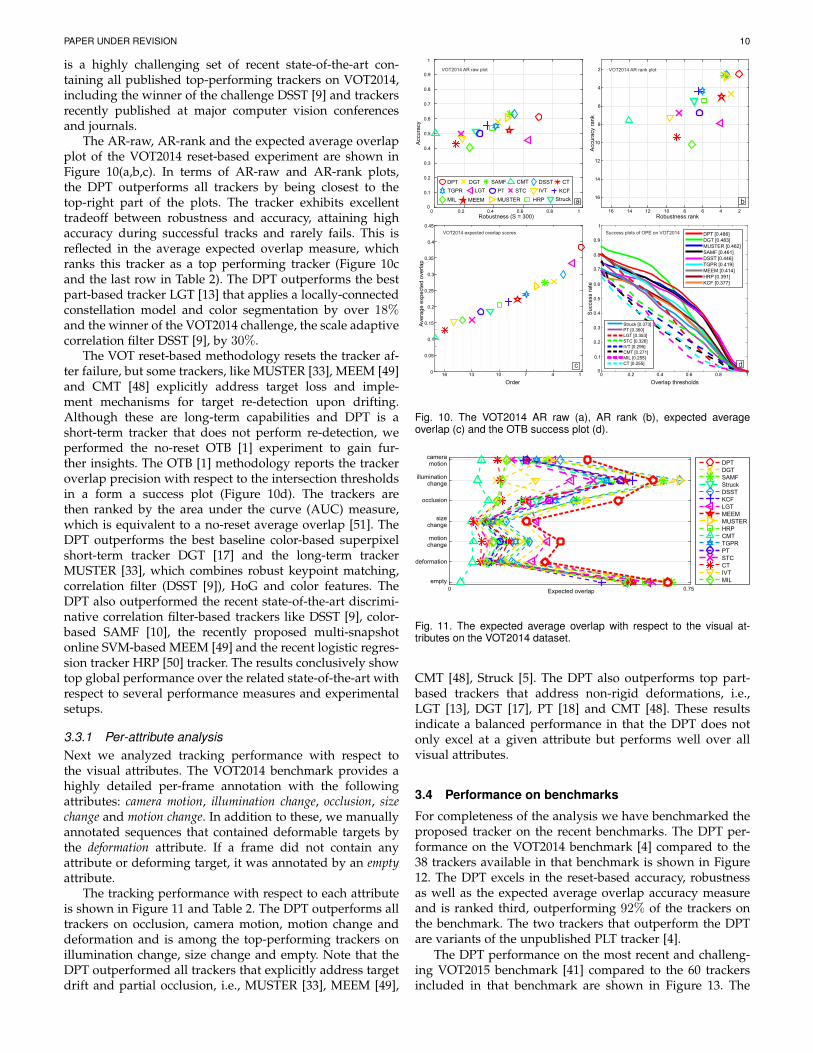
The AR-raw, AR-rank and the expected average overlapplot of the VOT2014 reset-based experiment are shown inFigure 10(a,b,c). In terms of AR-raw and AR-rank plots,the DPT outperforms all trackers by being closest to thetop-right part of the plots. The tracker exhibits excellenttradeoff between robustness and accuracy, attaining highaccuracy during successful tracks and rarely fails. This isreflected in the average expected overlap measure, whichranks this tracker as a top performing tracker (Figure 10cand the last row in Table 2). The DPT outperforms the bestpart-based tracker LGT [13] that applies a locally-connectedconstellation model and color segmentation by over 18%and the winner of the VOT2014 challenge, the scale adaptivecorrelation filter DSST [9], by 30%.
The VOT reset-based methodology resets the tracker af-ter failure, but some trackers, like MUSTER [33], MEEM [49]and CMT [48] explicitly address target loss and imple-ment mechanisms for target re-detection upon drifting.Although these are long-term capabilities and DPT is ashort-term tracker that does not perform re-detection, weperformed the no-reset OTB [1] experiment to gain fur-ther insights. The OTB [1] methodology reports the trackeroverlap precision with respect to the intersection thresholdsin a form a success plot (Figure 10d). The trackers arethen ranked by the area under the curve (AUC) measure,which is equivalent to a no-reset average overlap [51]. TheDPT outperforms the best baseline color-based superpixelshort-term tracker DGT [17] and the long-term trackerMUSTER [33], which combines robust keypoint matching,correlation filter (DSST [9]), HoG and color features. TheDPT also outperformed the recent state-of-the-art discrimi-native correlation filter-based trackers like DSST [9], color-based SAMF [10], the recently proposed multi-snapshotonline SVM-based MEEM [49] and the recent logistic regres-sion tracker HRP [50] tracker. The results conclusively showtop global performance over the related state-of-the-art withrespect to several performance measures and experimentalsetups.
3.3.1 Per-attribute analysisNext we analyzed tracking performance with respect tothe visual attributes. The VOT2014 benchmark provides ahighly detailed per-frame annotation with the followingattributes: camera motion, illumination change, occlusion, sizechange and motion change. In addition to these, we manuallyannotated sequences that contained deformable targets bythe deformation attribute. If a frame did not contain anyattribute or deforming target, it was annotated by an emptyattribute.
The tracking performance with respect to each attributeis shown in Figure 11 and Table 2. The DPT outperforms alltrackers on occlusion, camera motion, motion change anddeformation and is among the top-performing trackers onillumination change, size change and empty. Note that theDPT outperformed all trackers that explicitly address targetdrift and partial occlusion, i.e., MUSTER [33], MEEM [49],
0
0.1
0.2
0.3
0.4
0.5
0.6
0.7
0.8
0.9
1
0 0.2 0.4 0.6 0.8 1
Robustness rank246810121416
Accu
racy
ran
k
2
4
6
8
10
12
14
16
Robustness (S = 300)
Accu
racy
0
0.1
0.2
0.3
0.4
0.5
0.6
0.7
0.8
0.9
1
0.2 0.4 0.6 0.8 10
1471013160
0.05
0.1
0.15
0.2
0.25
0.3
0.35
0.4
0.45
Order
Ave
rag
e e
xp
ecte
d o
ve
rla
p
VOT2014 expected overlap scores
Overlap thresholds
Su
cce
ss r
ate
c
DPT [0.486]DGT [0.483]MUSTER [0.462]SAMF [0.461]DSST [0.446]TGPR [0.419]MEEM [0.414]HRP [0.391]KCF [0.377]
Success plots of OPE on VOT2014
Struck [0.373]PT [0.360]LGT [0.353]STC [0.326]IVT [0.295]CMT [0.271]MIL [0.255]CT [0.255] d
VOT2014 AR rank plot
ba
VOT2014 AR raw plot
DPT DGT SAMF
Struck
DSST
KCFLGT
MEEM MUSTER HRP
CMT
TGPR PT STC
CT
IVT
MIL
Fig. 10. The VOT2014 AR raw (a), AR rank (b), expected averageoverlap (c) and the OTB success plot (d).
0
DPTDGTSAMFStruckDSSTKCFLGTMEEMMUSTERHRPCMTTGPRPTSTCCTIVTMIL
occlusion
empty
illuminationchange
sizechange
motionchange
cameramotion
deformation
Expected overlap 0.75
Fig. 11. The expected average overlap with respect to the visual at-tributes on the VOT2014 dataset.
CMT [48], Struck [5]. The DPT also outperforms top part-based trackers that address non-rigid deformations, i.e.,LGT [13], DGT [17], PT [18] and CMT [48]. These resultsindicate a balanced performance in that the DPT does notonly excel at a given attribute but performs well over allvisual attributes.
3.4 Performance on benchmarks
For completeness of the analysis we have benchmarked theproposed tracker on the recent benchmarks. The DPT per-formance on the VOT2014 benchmark [4] compared to the38 trackers available in that benchmark is shown in Figure12. The DPT excels in the reset-based accuracy, robustnessas well as the expected average overlap accuracy measureand is ranked third, outperforming 92% of the trackers onthe benchmark. The two trackers that outperform the DPTare variants of the unpublished PLT tracker [4].
The DPT performance on the most recent and challeng-ing VOT2015 benchmark [41] compared to the 60 trackersincluded in that benchmark are shown in Figure 13. The

PAPER UNDER REVISION 11
TABLE 2The per-attribute expected average overlap, i.e., EAO measure, (Ω), reset-based overlap (O) and number of failures (F) for the top 10 ranked
trackers over 7 visual attributes: camera motion (CM), deformation (DE), empty (EM), illumination change (IC), motion change (MC), occlusion(OC), size change (SC). The arrows ↑ and ↓ indicate that “higher is better” and “lower is better”, respectively.
DPT LGT [13] DSST [9] DGT [17] SAMF [10] MUSTER [33] TGPR [26] MEEM [49] KCF [11] HRP [50]attr. EAO↑ O↑ F↓ Ω ↑ O↑ F↓ Ω ↑ O↑ F↓ Ω ↑ O↑ F↓ Ω ↑ O↑ F↓ Ω ↑ O↑ F↓ Ω ↑ O↑ F↓ Ω ↑ O↑ F↓ Ω ↑ O↑ F↓ Ω ↑ O↑ F↓CM 0.43 0.64 12.00 0.32 0.44 15.20 0.34 0.66 20.00 0.30 0.56 19.00 0.31 0.65 24.00 0.31 0.63 22.00 0.27 0.57 27.27 0.24 0.53 25.00 0.23 0.57 34.00 0.26 0.58 30.00DE 0.31 0.60 17.00 0.26 0.41 11.16 0.19 0.56 28.00 0.21 0.54 16.00 0.17 0.59 31.00 0.17 0.55 31.00 0.16 0.53 37.07 0.15 0.52 33.00 0.13 0.53 42.00 0.13 0.50 41.00EM 0.68 0.49 0.00 0.62 0.51 0.00 0.68 0.54 0.00 0.68 0.67 0.00 0.69 0.56 0.00 0.67 0.51 0.00 0.55 0.41 0.00 0.57 0.47 0.00 0.47 0.56 0.00 0.61 0.26 0.00IC 0.64 0.63 1.00 0.38 0.45 1.47 0.72 0.74 1.00 0.15 0.46 14.00 0.67 0.67 1.00 0.72 0.73 1.00 0.49 0.57 3.47 0.55 0.54 2.00 0.57 0.54 1.00 0.50 0.66 4.00MC 0.35 0.63 14.00 0.31 0.46 10.47 0.25 0.64 24.00 0.30 0.58 14.00 0.24 0.66 25.00 0.22 0.64 26.00 0.21 0.55 30.20 0.19 0.53 24.00 0.18 0.57 34.00 0.17 0.60 35.00OC 0.52 0.62 2.00 0.24 0.32 3.93 0.39 0.63 3.00 0.39 0.48 1.00 0.40 0.60 4.00 0.42 0.61 3.00 0.33 0.61 5.00 0.24 0.57 3.00 0.22 0.58 6.00 0.23 0.47 5.00SC 0.24 0.54 12.00 0.27 0.43 7.40 0.18 0.52 15.00 0.23 0.57 6.00 0.16 0.56 18.00 0.14 0.53 19.00 0.14 0.47 21.20 0.11 0.46 15.00 0.12 0.47 27.00 0.11 0.50 27.00Average 0.39 0.61 11.97 0.33 0.44 11.16 0.30 0.62 19.28 0.28 0.56 14.31 0.27 0.63 21.76 0.26 0.61 21.39 0.24 0.54 25.76 0.22 0.52 22.04 0.21 0.55 30.24 0.20 0.55 29.13
Robustness (S = 300)0 0.2 0.4 0.6 0.8 1
Accu
racy
0
0.1
0.2
0.3
0.4
0.5
0.6
0.7
0.8
0.9
1
Order15913172125293337
Ave
rag
e e
xpe
cte
d o
verla
p
0
0.1
0.2
0.3
0.4
0.5VOT2014 expected overlap scoresVOT2014 AR raw plot
DPT
SIR_PF
ABS
qwsEDFTEDFT aStruck
IIVTv2
VTDMG
MCTSAMF LT_FLO
Matrioska
BDF MatFlowPLT_13
IMPNCCStruck
ThunderStruck
IPRT
PLT_14
ACAT
eASMS
FoT
HMMTxD
ACT DSST DynMS PTp KCF FSDT
OGT DGT
CMT
LGTv1
IVT NCC FRT MIL
CT
Fig. 12. The AR raw plots and the expected average overlap accuracymeasures for VOT2014 benchmark [4]. Please see [4] for the trackerreferences.
tracker is ranked among the top 10% of all trackers, outper-forming 54 trackers (i.e., 90% of the benchmark). The DPToutperforms all fifteen part-based trackers and fourteencorrelation filter trackers, including the nSAMF, which is animproved version of [10] that applies color as well as fusionwith various models, and the recently published improvedStruck [52] that applies additional features and performsremarkably well compared to the original version [5]. TheVOT2015 provides a VOT2015 published sota bound com-puted by averaging performance of trackers published in2014/2015 in top computer vision conferences and journals.Any tracker with performance over this boundary is consid-ered a state-of-the-art tracker according to VOT. The DPT ispositioned well above this boundary and is considered astate-of-the-art according to the strict VOT2015 standards.
The DPT performance against 29 trackers available onthe standard OTB [1] benchmark is shown in Figure 14. TheDPT outperforms all trackers and is ranked top, exceedingthe performance of the second-best tracker by over 8%.
3.5 Qualitative analysis
Qualitative analysis is provided for further insights. Anexperiment was performed to demonstrate the effectivenessof part adaptations during significant partial occlusions. TheDPT was applied to a well-known sequence, in which theobject (face) undergoes repetitive partial occlusions by abook (see Figure 15). The DPT tracked the face withoutfailures. Figure 15 shows images of the face taken from thesequence along with the graph of color-coded part weightsw
(i)t . The automatically computed adaptation threshold is
shown in gray. Recall that part is updated if the weight
Order161116212631364146515661
Ave
rage e
xpect
ed o
verlap
0
0.05
0.1
0.15
0.2
0.25
0.3
0.35
0.4
VOT2015 published sota bound
Robustness (S = 100)0 0.2 0.4 0.6 0.8 1
Acc
ura
cy
0
0.1
0.2
0.3
0.4
0.5
0.6
0.7
0.8
0.9
1
DPT ACT
AOGTracker
ASMS CMT CT DAT DFT
DSST
DeepSRDCF
EBT FoT
FragTrack
HMMTxD HT IVT
KCF2 L1APG
LGT
LT_FLO MCT MDNet MEEM MIL
OAB OACF PKLTF
RobStruck
SCBT SODLT TGPR amt
baseline bdf cmil dtracker fct ggt kcf_mtsa kcfdp
kcfv2 loft_lite matflow mkcf_plus muster mvcft ncc nsamf
rajssc s3tracker sKCF sPST samf scebt sme srat
srdcf
struck2
sumshift
tric zhang
VOT2015 AR raw plot VOT2015 expected overlap scores
Fig. 13. The AR raw plots and the expected average overlap accuracymeasures for VOT2015 benchmark [41]. Please see [41] for the trackerreferences.
Overlap threshold
Su
cce
ss r
ate
0
0.1
0.2
0.3
0.4
0.5
0.6
0.7
0.8
0.9
1
Success plots of OPE on OTB13 DPT [0.541]SCM [0.499]Struck [0.474]TLD [0.437]ASLA [0.434]CXT [0.426]VTS [0.416]VTD [0.416]CSK [0.398]LSK [0.395]DFT [0.389]L1APG [0.380]MTT [0.376]OAB [0.370]LOT [0.367]MIL [0.359]IVT [0.358]CPF [0.355]TM-V [0.352]Frag [0.352]RS-V [0.346]ORIA [0.333]SemiT [0.332]KMS [0.326]BSBT [0.322]PD-V [0.308]CT [0.306]VR-V [0.268]SMS [0.229]MS-V [0.212]
0 0.1 0.2 0.3 0.4 0.5 0.6 0.7 0.8 0.9 1
Fig. 14. The OPE performance plot for the top trackers on the OTBbenchmark [1]. Please see [1] for the tracker references.
exceeds this threshold (Section 2.5). Observe that partialocclusions are clearly identified by the weight graphs, re-sulting in drift prevention and successful tracking throughpartial occlusions.
Additional qualitative examples are provided in Fig-ure 16. The first row in Figure 16 shows performance ona non-deformable target with fast-varying local appearance.

PAPER UNDER REVISION 12
50
Part 1 Part 2 Part 3 Part 4 Treshold
P1 2
3 4
0 50 100 150 200 250 300 350 400 4500
0.05
0.1
0.15
0.2
0.25
0.3
0.35
0.4
0.45
120 200 250 300 375
Initial positionsof parts
P
PP
Fig. 15. Qualitative tracking results of partially occluded object. A sketchof parts is shown on the right-hand side. Part weights are color-coded,with the update threshold shown in gray.
The DPT tracks the target throughout the sequence, whileholistic correlation- and SVM-based trackers [5], [9], [33]fail. The second, third and fourth row show tracking ofdeformable targets of various degrees of deformation. Thefourth row shows tracking of a gymnast that drasticallyand rapidly changes the appearance. Note that the DPTcomfortably tracks the target, while the related trackersfail. The first and second row in Figure 17 visualizes suc-cessful tracking performance on targets undergoing signif-icant illumination changes. The third row shows trackingthrough several long-term partial occlusions. Again, theDPT successfully tracks the target even though the bottompart remains occluded for a large number of frames. Theconstellation model overcomes the occlusion and continuestracking during and after the occlusions.
4 CONCLUSION
A new class of deformable parts trackers based on correla-tion filters is presented. The developed deformable partsmodel jointly treats the visual and geometric propertieswithin a single formulation, resulting in a convex optimiza-tion problem. The parts appearance models are updatedby online regression to result in Gaussian-like likelihoodfunctions and the geometric constraints are modeled as afully-connected spring system. We have shown that thedual representation of such a deformable parts model isan extended spring system and that minimization of thecorresponding energy function leads to a MAP inference onthe deformable parts model. A highly efficient optimizationcalled iterated direct approach (IDA) is derived for this dualformulation. A deformable parts correlation filter tracker(DPT) is proposed that combines a coarse object represen-tation with a mid-level constellation of deformable partsmodel in top-down localization and bottom-up updates.
The extensive analysis of the new spring-system op-timization method IDA showed remarkable convergenceand robustness properties. In particular, the IDA convergesmuch faster than the conjugated gradient descent, is nu-merically more robust and scales very well with increasingthe number of parts in the spring system. Our trackerwas rigorously compared against the state-of-the-art with
respect to several performance measures and experimentalsetups against sixteen state-of-the-art baselines. The DPTtracker outperforms the related state-of-the-art part-basedtrackers as well as state-of-the-art trackers that use a singleappearance model, including the winner of the VOT2014challenge and runs in real-time. Additional tests show thatimprovements come from the fully-connected constellationand the top-down/bottom-up combination of the coarserepresentation with the proposed deformable parts model.The DPT tracker was benchmarked on three recent highlychallenging benchmarks against 38 trackers on VOT2014 [4]benchmark, 60 trackers on VOT2015 [41] benchmark and29 trackers on the OTB [1] benchmark. The DPT attained astate-of-the-art performance on all benchmarks. Note that,since five KCFs [11] are used in DPT, the speed reduction isapproximately five times compared to the baseline KCF. Butthe boost in performance is significant. The DPT reducesthe failures compared to the baseline KCF by nearly 60%,the expected average overlap is increased by over 80% andthe OTB average overlap is increased by approximately 30%while still attaining real-time performance.
The proposed deformable parts model is highly extend-able. The dual formulation of the deformable constellationand the proposed optimizer are generally applicable asstand-alone solvers for deformable parts models. The ap-pearance models on parts can be potentially replaced withother discriminative or generative models or augmented toobtain a constellation of parts based on various featureslike key-points and parts of different shapes. The part-basedmodels like flocks of features [35], key-point-based [37], [48]and superpixel-based [17] typically use more parts than thetracker presented in this paper. Our analysis shows that theproposed optimization of the deformation model scales wellwith the number of parts, and could be potentially usedin these trackers as a deformation model. Parts could alsobe replaced with scale-adaptive parts, which could furtherimprove scale adaptation of the whole tracker. Alternatively,saliency regions could be used to improve localization.One way to introduce the saliency is at the coarse layerand another to apply it at the parts localization. Since themodel is fully probabilistic, it can be readily integrated withprobabilistic dynamic models. These will be the topics ofour future work.
REFERENCES
[1] Y. Wu, J. Lim, and M.-H. Yang, “Online object tracking: A bench-mark,” in Comp. Vis. Patt. Recognition, 2013, pp. 2411– 2418.
[2] A. Smeulders, D. Chu, R. Cucchiara, S. Calderara, A. Dehghan,and M. Shah, “Visual tracking: An experimental survey,” IEEETrans. Pattern Anal. Mach. Intell., vol. 36, no. 7, pp. 1442–1468, July2014.
[3] M. Kristan, R. Pflugfelder, A. Leonardis, J. Matas, F. Porikli,L. Cehovin, G. Nebehay, G. Fernandez, and T. e. a. Vojir, “Thevisual object tracking vot2013 challenge results,” in Vis. Obj. Track.Challenge VOT2013, In conjunction with ICCV2013, Dec 2013, pp.98–111.
[4] M. Kristan, R. Pflugfelder, A. Leonardis, J. Matas, L. Cehovin,G. Nebehay, T. Vojir, and G. et al. Fernandez, “The visual objecttracking vot2014 challenge results,” in Proc. European Conf. Com-puter Vision, 2014, pp. 191–217.
[5] S. Hare, A. Saffari, and P. H. S. Torr, “Struck: Structured outputtracking with kernels,” in Int. Conf. Computer Vision. Washington,DC, USA: IEEE Computer Society, 2011, pp. 263–270.

PAPER UNDER REVISION 13
5 120 240 360 480 600
5 150 350 550 600 725
5 80 140 200 270 320
95 125 145 160 180 205
Fig. 16. Qualitative comparative examples of tracking for DPT, DSST, MUSTER and Struck shown in green, red, magenta and cyan, respectively.
5 100 210 330 450 565
5 50 90 130 170 200
5 130 210 330 460 560
Fig. 17. Qualitative examples of DPT tracker on three sequences. Tracking bounding box is visualized with yellow color and four parts on mid-levelrepresentation are shown in blue.
[6] B. Babenko, M.-H. Yang, and S. Belongie, “Robust object trackingwith online multiple instance learning,” IEEE Trans. Pattern Anal.Mach. Intell., vol. 33, no. 8, pp. 1619–1632, Aug. 2011.
[7] H. Grabner, M. Grabner, and H. Bischof, “Real-time tracking viaon-line boosting,” in Proc. British Machine Vision Conference, vol. 1,2006, pp. 47–56.
[8] D. S. Bolme, J. R. Beveridge, B. A. Draper, and Y. M. Lui, “Visualobject tracking using adaptive correlation filters,” in Comp. Vis.Patt. Recognition. IEEE, 2010, pp. 2544–2550.
[9] M. Danelljan, G. Hager, F. S. Khan, and M. Felsberg, “Accuratescale estimation for robust visual tracking,” in Proc. British MachineVision Conference, 2014, pp. 1–11.
[10] Y. Li and J. Zhu, “A scale adaptive kernel correlation filter trackerwith feature integration,” in Proc. European Conf. Computer Vision,2014, pp. 254–265.
[11] J. F. Henriques, R. Caseiro, P. Martins, and J. Batista, “High-speedtracking with kernelized correlation filters,” IEEE Trans. PatternAnal. Mach. Intell., vol. 37, no. 3, pp. 583–596, 2014.
[12] D. Comaniciu, V. Ramesh, and P. Meer, “Kernel-based objecttracking,” IEEE Trans. Pattern Anal. Mach. Intell., vol. 25, no. 5,pp. 564–577, May 2003.
[13] L. Cehovin, M. Kristan, and A. Leonardis, “Robust visual trackingusing an adaptive coupled-layer visual model,” IEEE Trans. PatternAnal. Mach. Intell., vol. 35, no. 4, pp. 941–953, Apr. 2013.
[14] J. Kwon and K. M. Lee, “Tracking by sampling and integratingmultiple trackers,” IEEE Trans. Pattern Anal. Mach. Intell., vol. 36,no. 7, pp. 1428–1441, July 2014.
[15] M. E. Maresca and A. Petrosino, “Matrioska: A multi-level ap-proach to fast tracking by learning,” in Proc. Int. Conf. ImageAnalysis and Processing, 2013, pp. 419–428.

PAPER UNDER REVISION 14
[16] N. M. Artner, A. Ion, and W. G. Kropatsch, “Multi-scale 2dtracking of articulated objects using hierarchical spring systems,”Patt. Recogn., vol. 44, no. 4, pp. 800–810, 2011.
[17] Z. Cai, L. Wen, Z. Lei, N. Vasconcelos, and S. Li, “Robust de-formable and occluded object tracking with dynamic graph,” IEEETrans. Image Proc., vol. 23, no. 12, pp. 5497 – 5509, 2014.
[18] R. Yao, Q. Shi, C. Shen, Y. Zhang, and A. van den Hengel, “Part-based visual tracking with online latent structural learning,” inComp. Vis. Patt. Recognition, June 2013, pp. 2363–2370.
[19] M. Godec, P. M. Roth, and H. Bischof, “Hough-based tracking ofnon-rigid objects.” Comp. Vis. Image Understanding, vol. 117, no. 10,pp. 1245–1256, 2013.
[20] G. Zhu, J. Wang, C. Zhao, and H. Lu, “Part context learning forvisual tracking,” in Proc. British Machine Vision Conference, 2014,pp. 1–12.
[21] R. T. Collins, X. Liu, and M. Lordeanu, “Online selection ofdiscriminative tracking features,” IEEE Trans. Pattern Anal. Mach.Intell., vol. 27, no. 10, pp. 1631–1643, 2005.
[22] D. A. Ross, J. Lim, R.-S. Lin, and M.-H. Yang, “Incrementallearning for robust visual tracking,” Int. J. Comput. Vision, vol. 77,no. 1-3, pp. 125–141, May 2008.
[23] K. Zhang, L. Zhang, and M.-H. Yang, “Real-time compressivetracking,” in Proc. European Conf. Computer Vision, 2012, pp. 864–877.
[24] X. Mei and H. Ling, “Robust visual tracking and vehicle classifi-cation via sparse representation,” IEEE Trans. Pattern Anal. Mach.Intell., vol. 33, no. 11, pp. 2259–2272, Nov 2011.
[25] Z. Hong, X. Mei, D. Prokhorov, and D. Tao, “Tracking via robustmulti-task multi-view joint sparse representation,” in Int. Conf.Computer Vision, Dec 2013, pp. 649–656.
[26] J. Gao, H. Ling, W. Hu, and J. Xing, “Transfer learning based visualtracking with gaussian processes regression,” in Proc. EuropeanConf. Computer Vision, vol. 8691, 2014, pp. 188–203.
[27] S. Avidan, “Support vector tracking,” IEEE Trans. Pattern Anal.Mach. Intell., vol. 26, no. 8, pp. 1064–1072, Aug 2004.
[28] H. Possegger, T. Mauthner, and H. Bischof, “In defense of color-based model-free tracking,” in Comp. Vis. Patt. Recognition, 2015,pp. 2113–2120.
[29] P. Naidu, “Improved optical character recognition by matchedfiltering,” Optics Communications, vol. 12, no. 3, pp. 287–289, 1974.
[30] M. Zhang, J. Xing, J. Gao, and W. Hu, “Robust visual trackingusing joint scale-spatial correlation filters,” in Proc. Int. Conf. ImageProcessing. IEEE, 2015, pp. 1468–1472.
[31] Y. Li, J. Zhu, and S. C. Hoi, “Reliable patch trackers: Robustvisual tracking by exploiting reliable patches,” in Comp. Vis. Patt.Recognition, 2015, pp. 353–361.
[32] K. Zhang, L. Zhang, Q. Liu, D. Zhang, and M.-H. Yang, “Fastvisual tracking via dense spatio-temporal context learning,” inProc. European Conf. Computer Vision. Springer InternationalPublishing, 2014, pp. 127–141.
[33] Z. Hong, Z. Chen, C. Wang, X. Mei, D. Prokhorov, and D. Tao,“Multi-store tracker (muster): A cognitive psychology inspiredapproach to object tracking,” in Comp. Vis. Patt. Recognition, 2015,pp. 749–758.
[34] J. Hoey, “Tracking using flocks of features, with application toassisted handwashing,” in Proc. British Machine Vision Conference,vol. 1, 2006, pp. 367–376.
[35] T. Vojir and J. Matas, “The enhanced flock of trackers,” in Regis-tration and Recognition in Images and Videos, ser. Studies in Compu-tational Intelligence. Springer Berlin Heidelberg, 2014, vol. 532,pp. 113–136.
[36] B. Martinez and X. Binefa, “Piecewise affine kernel tracking fornon-planar targets,” Patt. Recogn., vol. 41, no. 12, pp. 3682–3691,2008.
[37] F. Pernici and A. Del Bimbo, “Object tracking by oversamplinglocal features,” IEEE Trans. Pattern Anal. Mach. Intell., vol. 36,no. 12, pp. 2538–2551, 2013.
[38] X. Yang, Q. Xiao, S. Wang, and P. Liu, “Real-time tracking via de-formable structure regression learning,” in Proc. Int. Conf. PatternRecognition, 2014, pp. 2179–2184.
[39] S. Duffner and C. Garcia, “PixelTrack: a fast adaptive algorithmfor tracking non-rigid objects,” in Int. Conf. Computer Vision, 2013,pp. 2480–2487.
[40] G. Duan, H. Ai, S. Cao, and S. Lao, “Group tracking: exploringmutual relations for multiple object tracking,” in Proc. EuropeanConf. Computer Vision. Springer, 2012, pp. 129–143.
[41] M. Kristan, J. Matas, A. Leonardis, M. Felsberg, L. Cehovin, G. Fer-nandez, T. Vojir, G. Hager, G. Nebehay, and R. et al. Pflugfelder,“The visual object tracking vot2015 challenge results,” in Int. Conf.Computer Vision, 2015.
[42] M. Danelljan, F. Shahbaz Khan, M. Felsberg, and J. van de Weijer,“Adaptive color attributes for real-time visual tracking,” in Comp.Vis. Patt. Recognition, 2014, pp. 1090–1097.
[43] M. Kristan, J. Pers, V. Sulic, and S. Kovacic, “A graphical modelfor rapid obstacle image-map estimation from unmanned surfacevehicles,” in Proc. Asian Conf. Computer Vision, 2014, pp. 391–406.
[44] A. Diplaros, N. Vlassis, and T. Gevers, “A spatially constrainedgenerative model and an em algorithm for image segmentation,”IEEE Trans. Neural Networks, vol. 18, no. 3, pp. 798 – 808, 2007.
[45] N. Dalal and B. Triggs, “Histograms of oriented gradients forhuman detection,” in Comp. Vis. Patt. Recognition, vol. 1, June 2005,pp. 886–893.
[46] I. Griva, S. G. Nash, and A. Sofer, Linear and Nonlinear Optimization,Second Edition. Siam, 2009.
[47] M. Kristan, J. Matas, A. Leonardis, T. Vojir, R. Pflugfelder, G. Fer-nandez, G. Nebehay, F. Porikli, and L. Cehovin, “A novel perfor-mance evaluation methodology for single-target trackers,” IEEETrans. Pattern Anal. Mach. Intell., 2016.
[48] G. Nebehay and R. Pflugfelder, “Clustering of static-adaptivecorrespondences for deformable object tracking,” in Comp. Vis.Patt. Recognition, 2015, pp. 2784–2791.
[49] J. Zhang, S. Ma, and S. Sclaroff, “MEEM: robust tracking viamultiple experts using entropy minimization,” in Proc. EuropeanConf. Computer Vision, 2014, pp. 188–203.
[50] N. Wang, J. Shi, D.-Y. Yeung, and J. Jia, “Understanding anddiagnosing visual tracking systems,” in Int. Conf. Computer Vision,2015.
[51] L. Cehovin, A. Leonardis, and M. Kristan, “Visual object trackingperformance measures revisited,” IEEE Trans. Image Proc., vol. 25,no. 3, pp. 1261 – 1274, 2016.
[52] S. Hare, S. Golodetz, A. Saffari, V. Vineet, M. Cheng, S. Hicks, andP. Torr, “Struck: Structured output tracking with kernels,” IEEETrans. Pattern Anal. Mach. Intell., 2016.
Alan Lukezic received the Dipl.ing. and M.Sc.degrees at the Faculty of Computer and Infor-mation Science, University of Ljubljana, Sloveniain 2012 and 2015, respectively. He is currentlya researcher at the Visual Cognitive SystemsLaboratory, Faculty of Computer and InformationScience, University of Ljubljana, Slovenia as aresearcher. His research interests include com-puter vision, data mining and machine learning.
Luka Cehovin received his Ph.D from the Fac-ulty of Computer and Information Science, Uni-versity of Ljubljana, Slovenia in 2015. Currentlyhe is working at the Visual Cognitive SystemsLaboratory, Faculty of Computer and Informa-tion Science, University of Ljubljana, Sloveniaas a teaching assistant and a researcher. Hisresearch interests include computer vision, HCI,distributed intelligence and web-mobile tech-nologies.
Matej Kristan received a Ph.D from the Facultyof Electrical Engineering, University of Ljubljanain 2008. He is an Assistant Professor at the Vi-CoS Laboratory at the Faculty of Computer andInformation Science and at the Faculty of Elec-trical Engineering, University of Ljubljana. Hisresearch interests include probabilistic methodsfor computer vision with focus on visual tracking,dynamic models, online learning, object detec-tion and vision for mobile robotics.