paklay hydropower project
TRANSCRIPT

PAKLAY HYDROPOWER PROJECT
5th MRC Regional Stakeholder Forum
20 September 2018

2
Mekong Mainstream Project
4th of the 7 hydropower projects along the Mekong mainstream in Lao PDR
Project Location
➢ 240km from Vientiane Capital
➢ Straight-line distance to Lao-Thai border approx. 60km
1.1 Project Overview

3
PROJECT FEATURES
Type of Plant Run-of-river
Type of DamConcrete Gravity Dam
Maximum Dam Height 51.2m
Dam Crest Length 942.75m
KEY PARAMETERS
Installed Capacity770MW (14×55MW)
Annual Utilization Hours 5357h
Annual Average Generating Capacity
4124 GWh
Preparation Period 2 years
Total Construction Period
7 years
Estimated Commercial Operation Date
2027
1.1 Project Overview

4
Project Structures
Navigation Locks
Single-Stage ship lock Capacity for passing
500t ships Size of navigation lock:
120m*12m*4m
Fish Passage
1017m length, 6m width, 3m depth
A large resting pool considered
Spillway
EL 220m: 11 open-type high-level surface bays (16m*20m)
EL 212m: 3 open-type low-level surface bays(16m*28m) EL 205m: 2 sediment flushing bottom outlets(10m*10m)
Power House
Capacity: 770 MW 55 MW of bulb generating unit 14 Units
1.1 Project Overview

5
1.2.1 Feasibility Study
Feb 2011
FSR(Lower Dam Site)
Oct 2012
Geological Exploration and FSR(Upper Dam Site)
Sep 2015
MRC Compliance Review
Jan 2017
MRC Compliance Review Report (Final)
Feb 2009
Water Level Comparison And Selection Report(Lower Dam Site, Draft)
Mar 2011
Interim Approval(Lower Dam Site)
Apr 2014
FSR Review by CREEI
Oct 2015
Interim Approval(Upper Dam Site)
Mar 2017
FSR (Final)
11 years of profound study with involvement of excellent designing firm and internationalconsultants, laying a solid foundation for the project implementation and operation.
2007Exploration Survey
Aug 2017
Final Approval
1.2 Project Progress

6
1.2.2 Environment & Social Impact Assessment (ESIA)
IEE & TOR Approval
Commencement of
ESIA
Public Consultation
ESIA Report
Submission
ESIA FinalApproval
Approaching
Completed and updated 8 ESIA related reports:
• Transboundary Environmental and Social Impact Assessment (TBESIA)
• Cumulative Impact Assessment (CIA)• Environmental Impact Assessment (EIA)• Environmental Management and Monitoring
Plan (EMMP)
• Social Impact Assessment (SIA)• Social Management and Monitoring Plan (SMMP)• Resettlement Action Plan (RAP) • Health Impact Assessment (HIA)
ESIA Interim
Certificate
√ - Completed
1.2 Project Progress

1.2 Hydrology

8
1.2 Hydrology
2 Work Plan for Next Stage1.2.1 Runoff
a) By extending the data series of the Luang Prabang Hydrological Station and the Chiang KhanHydrological Station to 2015, it can be obtained that the average annual discharges at the twostations are 3,820 m3/s and 4,240 m3/s respectively through statistical analysis.

9
2 Work Plan for Next Stage1.2.1 Runoff
b) it can be obtained that the average annual
discharge at the dam site is 4,060 m3/s
c) the runoff at the dam site under the impacts of
upstream cascades has been analyzed and
calculated;
Month January February March April May June July August September October November December Annual
Q 1740 1310 1120 1150 1690 3210 6610 10250 9280 5880 3810 2440 4060
% 3.59 2.70 2.31 2.37 3.49 6.62 13.63 21.14 19.14 12.13 7.86 5.03 100
Monthly Average Discharge Over Years at the Dam Site
Unit: m3/s
1.2 Hydrology

10
2 Work Plan for Next Stage1.2.2 Stage-Discharge Relationship
the stage - discharge relationship at the dam site calculated at this stage is basically proper;
1.2 Hydrology

11
2 Work Plan for Next Stage1.2.3 Analysis on Impacts of Upstream Reservoirs on Runoff at Paklay Dam Site
Analysis on impacts of reservoirs on the main stream of the Lancang River on runoff at Paklay Dam Site
Considering regulation and storage impacts of reservoirs at the middle-lower reaches of the Lancang River, the
average annual discharge at the Paklay Dam Site is consistent with that under natural conditions. However, with
a relatively large variation in annual distribution of discharge, the average discharge in flood season (June ~
October) will decrease by about 14%, and that in dry season (December ~ next May) will increase by about 50%.
1.2 Hydrology

12
2 Work Plan for Next Stage
1.2.4 Sediment
• The analysis and calculation results indicate that there is average annual suspended
load discharge and average annual suspended load sediment content of 16.50x10⁶ t and
0.129 kg/m³ respectively at the dam site;
1.2 Hydrology

1.3 Geology

14
1.3.1 Regional Geology
According to USGS information, no major
earthquake has occurred within a radius of
150km since 2150 BC ; 4 earthquakes has
occurred within a radius of 150 km since
1973 (M4.7 as the maximum) and no
earthquake has occurred within a radius of 30
km.
Seismic Distribution since 1973
1.3 Geology

15
1.3.1 Regional Geology
According to the seismic safety
evaluation and research results, it is
recommended that the peak ground
acceleration be 0.384 g (SEE and
MCE) for that with an exceedance
probability of 2% in 100 years.
Ground Motion Parameters of
Bedrock at the Recommended Dam
Site
Designed
seismic
dynamic
parameter
50-year
exceedance
probability
100-year exceedance probability
10% 50% 4% 2%
Return years 475 145 2475 5000
Amax (gal) 130.0 64.9 284.3 376.8
βmax 2.38 2.32 2.44 2.49
Tg (sec) 0.26 0.25 0.27 0.28
Ah(g) (=
Amax/980)
0.133 0.066 0.290 0.384
γ 1 1 1 1
1.3 Geology

16
1.3.2 Geological Conditions of the Upper Dam Site
The strata outcropping at the upper dam site are of
mica quartz schist and blastopsammite. The schist
has low strength and weak weathering resistance;
the blastopsammite has high strength. Bedrock
weathering is shallow in the riverbed and relatively
deep in bank slopes.
ZB0
7
ZB1
9ZB19
ZB07
1.3 Geology

1.4 Project Planning

18
1.4 Project Planning
Paklay HPP will mainly supply power to Thailand.
1.4.1 Power Market Analysis

19
In the feasibility study, the
full supply level of Paklay
HPP is considered as
240.00 m. It have a min.
operating level of 239 m
and a live storage of 54.8
million m3.
1.4.2 Full Supply LevelCascade HPP Development on the Main Stream of Mekong River
(within Laos)
1.4 Project Planning

1.5 Project Layout and Main Structures

21
1.5 Project Layout and Main Structures
1.5.1 Dam Site Comparison
The upper dam site and lower dam site are
proposed for comparison.
After an overall comparison, the upper dam
site is recommended in this stage. Flow direction
Previously planned dam
site (lower dam site )
Upper dam
site
Namphoun River
Villages and towns at
confluence of Namphoun
River

22
1.5.2 Project Layout
The project consists of the
water-release and energy dissipation
structures, water–retaining structure,
powerhouse, shiplock and fishway.
From left to right along the dam, the
structures are fishway, left non-
overflow section, retaining-type
powerhouse section, overflow
section (energy dissipator by
hydraulic jump), shiplock section,
and right non-overflow section.
Lock
High-level
surface bay
High-level surface bay (with a stilling
basin)
Low-level
surface bay
Sediment flushing
bottom outlet
Powerhouse
1.5 Project Layout and Main Structures

23
1.5.3 Main Structures The overflow section consists of 11 open-type high-
level surface bays, 3 open-type low-level surface
bays and 2 sand flushing outlets.
open-type high-level surface bays:16.0m×20.0m.
open-type low-level surface bays:16.0m×28.0m.
sand flushing outlets:10.0m×10.0m.
1.5 Project Layout and Main Structures

24
1.5.3 Main Structures
The hydraulic jump energy dissipator is proposed.
1.5 Project Layout and Main Structures

25
1.5.3 Main Structures
The main powerhouse consists of the
machine hall and erection bay.
The machine hall has a net width of
21.00m, and consists of three floors from top
down, namely operation floor, busbar floor
and passage floor. The setting elevation of
unit is 208.50m.
1.5 Project Layout and Main Structures

26
1.5.3 Main Structures
Navigation structure: In this stage, the single-stage ship lock alternative is recommended. The
effective size of the ship lock is 120.0m×12.0m×4m(L×W×water depth) as per MRC. The
ship lock system consists of the upper approach, ship lock and lower approach.
1.5 Project Layout and Main Structures

27
1.5.3 Main Structures
Fishway structure: The two-side vertical-slot fishway is recommended.
1.5 Project Layout and Main Structures

28
1.5.3 Main Structures
Fishway structure:The fishway is arranged on the slope on the
left side of powerhouse, with a total length of 830.00m
(including 25m-long Denil section at the inlet), and a gradient of
7.68%. The two-side vertical-slot fishway section is 805.00m
long, with an average gradient of 2.12%. The fishway inlet is
connected to the fish collection system, and its outlet is arranged
150m upstream of the power intake, with one bulkhead gate.
1.5 Project Layout and Main Structures

1.6 Construction Planning

30
1.6 Construction Planning
1.6.1 Construction Diversion
Stage-I Construction
Diversion The stage-I cofferdam is used
for closing the water release
structure, navigation lock and right-
bank non-overflow dam, while the
left river bed is used for
overflowing and navigation.
Diversion standard: 20-year
flood with a discharge of 23,500
m³/s.
Stage-I
cofferdam

31
1.6.1 Construction Diversion
The stage-II cofferdam is used
to close the main powerhouse,
fishway and left-bank non-overflow
dam, while the water release
structure is used for overflowing and
the lock is used for navigation.
Diversion standard: 20-year
flood with a discharge of 23,500
m³/s before power generation and
50-year flood with a discharge of
26,100 m³/s after power generation.
Stage-II
cofferdam
Stage-II Construction
Diversion
1.6 Construction Planning

32
Hydrologic Survey at Damsite Section
a) the temporary water level, discharge and
sediment measurement at the damsite
section was carried out.
b) the bed material sampling and grading
analysis was conducted.
CNR Review Comment: The hydrologic
survey at the dam site section should be
supplemented.
Modification:
2.1 Hydrology

33
c) the water level gauging station at the dam site was
restored and manual water level observation started.
d) manual staff gauge and automatic gauging station for
Paklay hydrological station were built.
Modification:
Water Level Gauging Station at Damsite
Automatic Stage Recorder
Staff Gauge
2.1 Hydrology
2.1.2 Hydrologic Survey at Damsite Section

34
e) the flow measurement with
ADCP and conventional
velocity meters as well as
sediment sampling and
analysis was started.
2.1.2 Hydrologic Survey at Damsite Section
Modification:
Sediment Sampling and Gradation Analysis
2.1 Hydrology

35
Runoff and Flood
b) The runoff at the damsite has been analyzed and checked based on the damsite
measurements and the processed data and the collected data;
Month Jan. Feb. Mar. Apr. May Jun. Jul. Aug. Sep. Oct. Nov. Dec.Annua
l
Q 1,740 1,310 1,120 1,150 1,690 3,210 6,610 10,250 9,280 5,880 3,810 2,440 4,060
% 3.59 2.70 2.31 2.37 3.49 6.62 13.63 21.14 19.14 12.13 7.86 5.03 100
Mean Monthly Discharges at Damsite from 1960 to 2015Q:m3/s
CNR Review Comment: The runoff and flood should be checked.
Modification:
2.1 Hydrology

36
Paklay Reservoir Operation Mode
CNR Review Comment: The reservoir operation mode should follow the operation principles of run-of-
river hydropower stations.
Modification: The reservoir operation mode has been adjusted following the operation principles of run-of-
river hydropower stations. For details, see the figure below:
2.1 Hydrology

37
2.2.1 Basic Information and the Suspended Load Sediment at the Dam site
a) The sediment data were additionally collected.
b) The suspended load sediment results at the dam site were analyzed and calculated;
c) The sediment results were checked and reviewed.
CNR Review Comment: Additional basic information should be collected and the suspended load
sediment results should be checked at the dam site.
Modification:
2.2 Sediment

38
Suspended Load Sediment Gradation
CNR Review Comment: The suspended load sediment gradation should be analyzed.
Modification:
a) Analysis and collation were conducted for sediment gradation sampling results, as well as the bedload
sediment gradation sampling results;
b) Comparison and analysis were conducted for the suspended load sediment grain gradation results obtained
in different periods;
2.2 Sediment

39
Flood Water Surface Profile Measurement and Channel Roughness Coefficient Calibration
In August 2016, we conducted flood water surface profile measurement at the river reaches of the Paklay
reservoir area.
2.2 Sediment

40
2D Sediment Numerical Simulation for Project Area — River Reaches Upstream of the Dam
Distribution of Sediment Scouring and Deposition Thickness of River
Reaches Upstream of the Dam Area (20-year Operation of Reservoir)
Distribution of Sediment Scouring and Deposition Thickness of River
Reaches Upstream of the Dam Area (40-year Operation of Reservoir)
Sedimentation is seldom seen at the main stream of the river course and frequently at the river bays. The reservoir
has a maximum sedimentation thickness of about 13 m after 40-year operation.
a) Overall analysis on sediment scouring and deposition for river reaches upstream of the dam area
2.2 Sediment

41
a) Analysis of sediment scouring and deposition
landform for river reaches downstream of the dam
Landform Elevation Downstream of
the Dam After 5 Years of Reservoir Operation
Distribution of Sediment Scouring and Deposition Thickness
Downstream of the Dam After 5 years of Reservoir Operation
2D Sediment Numerical Simulation for Project Area — River Reaches Downstream of the Dam
2.2 Sediment

2.3 Dam Safety

43
2.3.1 Project Layout
Layout Plan
Based on the original recommended
scheme, the erection bay ② is moved
to the right end of the powerhouse
and two sediment flushing bottom
outlets are arranged below the
erection bay ②. Three low-level
surface bays for flood releasing &
sediment flushing are arranged
between the erection bay ② and the
original flood releasing surface bays.
The twelve surface bays in the
original scheme is reduced to eleven.
Deep grooves are excavated both
upstream and downstream of the low-
level and high-level surface bays, and
connected with the upstream and
downstream thawing channels.
Navigatio
n lock
High-level
surface
bay
High-level surface bay
(with a stilling basin)
Low-level
surface
bay
Sediment
flushing bottom
outlet
Powe
rhous
e
2.3 Dam Safety
44
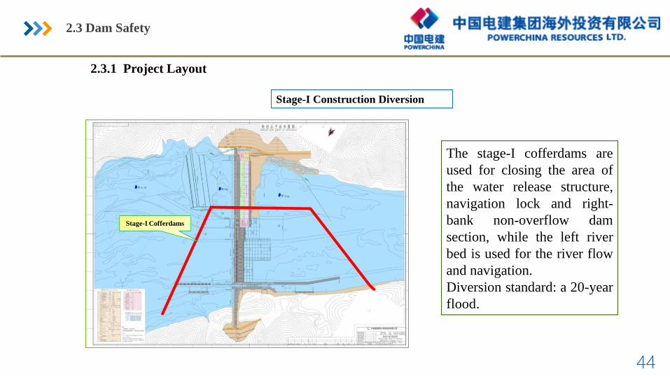
Stage-I Construction Diversion
The stage-I cofferdams are
used for closing the area of
the water release structure,
navigation lock and right-
bank non-overflow dam
section, while the left river
bed is used for the river flow
and navigation.
Diversion standard: a 20-year
flood.
2.3.1 Project Layout
Stage-I Cofferdams
2.3 Dam Safety

45
Stage-II Construction Diversion
The stage-II cofferdams are
used to enclose the area of
main powerhouse, fish way
and left-bank non-overflow
dam section, while the water
release structure is used for
flow pass and the navigation
lock is used for navigation.
Diversion standard: a 20-year
before power generation; and a
50-year flood after power
generation.
2.3.1 Project Layout
Stage-II Cofferdams
2.3 Dam Safety

46
Integral Hydraulic Model Test
Fig. 1.1 Simulation Range by Integral Hydraulic Model of PakLay HPP
2.3 Dam Safety

47
Flow pattern Chart for Q= 34,895 m³/s
(Full Opening of Gates at
2 Bottom outlets and 14 Surface Bays)
Flow pattern Chart for Q= 16,700 m³/s (Units
operating at rated output+ 5 m-deep Opening
of ①②③ Surface Bays
+ 7 m-deep Opening of ④⑥⑧ Surface Bays
+ 6 m-deep Opening of ⑤⑦ Surface Bays
+ 1 m-deep Opening of ⑨⑩⑪⑫⑬⑭Surface Bays)
Pictures of the Integral
Hydraulic Model Test.
Integral Hydraulic Model Test
2.3 Dam Safety

48
Scour Pit at Q = 16,700 m³/s
(8.33 m-ddep Opening of ①②③Surface Bays
+ 11 m-deep Opening of ④⑤⑥⑦⑧Surface Bays
+ 2 m-deep Opening of ⑨⑩⑪⑫⑬⑭ Surface Bays)
Scour Pit at Q = 39,040 m³/s
(Full Opening of 2 Bottom Outlets + 14 Surface Bays)
Integral Hydraulic Model Test
Pictures of the Integral
Hydraulic Model Test.
Scour pit
2.3 Dam Safety

49
Integral Model Test for Construction Diversion
Simulation Range of Integral Model for Construction Diversion at Paklay HPP
CNR Review Comment: It is suggested to add integral model test for construction diversion.
Modification: The model test shows that the construction diversion layout can meet the
design requirements and the navigation during construction .
2.3 Dam Safety

50
Flow pattern at a 20-year Flood (Q=23174m3/s)
Flow Velocity along the Left Side of
Longitudinal Cofferdam
-4
-3
-2
-1
0
1
2
-250
-200
-150
-100
-50 0
50
100
150
200
250
300
流速m
桩号m
工况1-4 工况1-5 工况1-6 工况1-7
Pictures and Results of Model Test for Stage I Construction Diversion:
2.3.4 Integral Model Test for Construction Diversion
2.3 Dam Safety

51
Flow pattern at a 20-year Flood (Q= 23,158 m3/s)
2.3.4 Integral Model Test for Construction Diversion
Pictures and Results of Model Test for Stage II Construction Diversion:
2.3 Dam Safety

52
2.3.5 Adjustment in Seismic Design Standard
CNR Review Comment: Considered earthquakes should be clarified and unified
throughout feasibility study (MCE, OBE, SEE). No table of seismic parameters is given.
Modification: The seismic hazard assessment of Paklay HPP is conducted by a third
party, the peak ground acceleration is 0.384 g for 100-year exceeding probability of 2%.
2.3 Dam Safety

2.5 Fish Way

54
2.5.1 Connection of the Downstream Entrance of the Fish Way with the Bottom of the Riverbed
Layout of Downstream Entrance
Layout of Upstream Entrance
The water flow at the upstream entrance is gentle, and
the change of water flow at the fish way entrance can
help the fishes find the entrance.The downstream entrance is arranged about 270m
downstream of the powerhouse at the bank, where
the riverbed is flat and the conditions for fish
guiding are favorable.
Brazilian Experts’ Review Comment: The downstream entrance of the fish way should be connected
with the bottom of the riverbed.
Modification: The layout of the upstream and downstream entrances of the fish way has been modified.
2.5 Fish Way

55
2.5.2 Large Resting Pool
Brazilian Experts’ Review Comment: A large resting pool should be added.
Modification: A large resting pool (about 56m long, 22m wide and 4.5m deep) has
been added in the middle section of fishway, where the fishes can take a rest and find
food so as to have energy to swim upstream.
2.5 Fish Way

56
3.2 Scope of trans-boundary and social-economic impacts
assessment
➢Scope and study zone
✓ Key biophysical and social condition (before the project)• Hydrology and Mekong River Flows• Sedimentation• Fish Migration and Fisheries • Navigation• Water Quality• Dam Safety • Socio-Cultural and Economic
✓ Transboundary and Cumulative Impacts Issues• Hydrology• Sedimentation• Fish Migration and Fisheries • Navigation• Water Quality• Dam Safety • Socio-Cultural and Economic
• Zone 1: Northern Laos – Pak Tha(KM 2281) to Pak Heuang (KM1736)
• Zone 2: Thai-Laos – Pak Heuang(KM 1736) to Ban Woenbuk (KM904)
• Zone 3: Southern Laos – BanWoenbuk (KM 904) to Cambodianborder (KM 723)
• Zone 4: Cambodia – Cambodiaborder (KM 723) to VietnamBorder (KM218)
• Zone 5: Southern Vietnam –Vietnam border (KM 218) toMekong Delta (KM 0)

57
3.6 Consultations and Field Surveys
Consultations Field SurveysData Collection

58
3.6 Consultations and Field Surveys
• Public Consultation Conference• Village Level • District and Provincial Level• National Level
• International Regional Level• Consultation with Other Stakeholders
➢Public Participation

59
3.7.7 Socio-Cultural and Economic
• Potential risks of domestic and irrigation water uses.• Potential risks of downstream cropping.• Potential risks of downstream health and nutrition.• Potential risks of downstream tourism.• Potential risks of Socio-political conflicts.
➢Impacts ➢Mitigating Measures
• provide alternatives for improved drinking water supplies for directaffected villages in downstream.
• Before moving resettlers to the resettlement sites, to check and analyzeboth water quantity and quality of the potential sources of water supply.In cases of insufficient water supplies, to prepare water storage such asreservoir or ponds to store water sufficiently for the resettlement sites.
• Select specific routes to transport construction material and equipment toavoid regular traffic.
• After the consultation, a village warning system will be installed asdiscussed in the consultation process during the early operation stage.
• To collaborate with EDL for rural electrification to be provided in theproject affected villages.
• To carry out a public health education campaign on hygienic conditions,disease prevention and health promotion to ensure understanding andincrease the awareness of the local population.
• To provide with sustainable agricultural alternative namely land forresettlers.
• Opening and closing time must be posted at the entrance of the Projectsite at all times.
• To pay full compensation, construct resettlement villages and providelivelihood restoration supporting.
Proposed Resettlement village

60
CNR and IÁV released the final review report on the Pak Lay HPP in Jan 2017. At the same time, CNR completed
an integrated report covering 4 mainstream projects (Pak Beng, Pak Lay, Sanakham and Phou Ngoy), where Pak
Lay HPP is one of them.
60
4.1 Conclusions
