pacsystems* rx3i · the pns manages profinet communication and module configuration between an i/o...
TRANSCRIPT

GEIntelligent Platforms
GFK-2737E
PACSystems* RX3iPROFINET ScannerManualJune 2015
For public disclosure

These instructions do not purport to cover all details or variations in equipment, nor to provide for every possiblecontingency to be met during installation, operation, and maintenance. The information is supplied for informationalpurposes only, and GE makes no warranty as to the accuracy of the information included herein. Changes, modifications,and/or improvements to equipment and specifications are made periodically and these changes may or may not be reflectedherein. It is understood that GE may make changes, modifications, or improvements to the equipment referenced herein or tothe document itself at any time. This document is intended for trained personnel familiar with the GE products referencedherein.
This document is approved for public disclosure.
GE may have patents or pending patent applications covering subject matter in this document. The furnishing of thisdocument does not provide any license whatsoever to any of these patents.
GE provides the following document and the information included therein as is and without warranty of any kind, expressedor implied, including but not limited to any implied statutory warranty of merchantability or fitness for particular purpose.
For further assistance or technical information, contact the nearest GE Sales or Service Office, or an authorized GE SalesRepresentative.
Revised: June 2015Issued: Aug 2013
Copyright © 2013 - 2015 General Electric Company, All rights reserved.___________________________________* Indicates a trademark of General Electric Company and/or its subsidiaries.All other trademarks are the property of their respective owners.
Refer to the section, Contact Information for support on this product.
Please send documentation comments or suggestions to [email protected]
For public disclosure

Document UpdatesRevision Location Description
Rev E,April 2015
The section, SFPModule Types
Corrected data for IC695SPF010 in table
Rev D,May 2014
The chapter,Configuration
The section, Configuring Module Parameters, added Universal Analog Input Moduleand Power Sync and Measurement Module and their rules to the table, the section,RX3i PROFINET Scanner Configuration Validation, added IC695ALG600 to the table.
Related DocumentsTitle Doc #PACSystems CPU Reference Manual GFK-2222
PACSystems Hot Standby CPU Redundancy User Manual GFK-2308
PACSystems RX3i System Manual GFK-2314
PACSystems RX3i High-speed Counter Modules User Manual GFK-2441
PACSystems RX3i PROFINET Controller Manual GFK-2571
PACSystems RX3i PROFINET Controller Command Line Interface Manual GFK-2572
PACSystems RX3i PROFINET Scanner Manual GFK-2737
PACSystems RX3i Power Sync and Measurement System Manual GFK-2749
PACSystems RXi ICRXICTL000 Distributed I/O Controller User's Manual GFK-2816
PROFINET I/O Devices Secure Deployment Guide GFK-2904
PACSystems RX7i & RX3i CPU Programmer's Reference Manual GFK-2950
GFK-2737E Manual 3For public disclosure

Safety Symbol Legend
Warning
Indicates a procedure, condition, or statement that, if not strictly observed, could result inpersonal injury or death.
Caution
Indicates a procedure, condition, or statement that, if not strictly observed, could result indamage to or destruction of equipment.
Attention
Indicates a procedure, condition, or statement that should be strictly followed to improvethese applications.
For public disclosure

Contact InformationIf you purchased this product through an Authorized Channel Partner, then contact the seller directly.
General Contact Information
Online technical support and GlobalCare http://support.ge-ip.com
Additional information http://www.ge-ip.com/
Solution Provider [email protected]
Technical Support
If you have technical problems that cannot be resolved with the information in this manual, please contact us bytelephone or email, or on the web at http://support.ge-ip.com
Americas
Online Technical Support http://support.ge-ip.com
Phone 1-800-433-2682
International Americas Direct Dial 1-780-420-2010 (if toll free 800 option is unavailable)
Technical Support Email [email protected]
Customer Care Email [email protected]
Primary language of support English
Europe, the Middle East, and Africa
Online Technical Support http://support.ge-ip.com
Phone + 800-1-433-2682
EMEA Direct Dial+ 420-23-901-5850 (if toll free 800 option is unavailable or dialing froma mobile telephone)
Technical Support Email [email protected]
Customer Care Email [email protected]
Primary languages of support English, French, German, Italian, Czech, Spanish
Asia Pacific
Online Technical Support http://support.ge-ip.com
Phone+ 86-400-820-8208+ 86-21-3217-4826 (India, Indonesia, and Pakistan)
Technical Support Email
[email protected] (China)
[email protected] (Japan)
[email protected] (remaining Asia customers)
Customer Care [email protected]
[email protected] (China)
GFK-2737E Manual 5For public disclosure

Notes
6 GFK-2737E PACSystems RX3i PROFINET ScannerFor public disclosure

Contents1 Introduction ....................................................................................................................................... 91.1 RX3i PROFINET Scanner Overview......................................................................................................... 101.2 RX3i PROFINET Scanner Specifications ................................................................................................... 111.3 RX3i PROFINET Scanner Controls and Indicators....................................................................................... 121.3.1 LEDs on the PROFINET Scanner Module ........................................................................................... 121.3.2 SD Card Slot .................................................................................................................................. 131.3.3 Pushbutton..................................................................................................................................... 131.3.4 USB Port....................................................................................................................................... 131.3.5 Ethernet Port Connections ................................................................................................................ 13
1.4 PROFINET Operation Overview .............................................................................................................. 141.4.1 PROFINET Communications ............................................................................................................ 141.4.2 Application Relationships ................................................................................................................. 141.4.3 Types of PROFINET Communications................................................................................................ 161.4.4 Operations of the PROFINET Scanner ................................................................................................ 161.4.5 I/O Scanning .................................................................................................................................. 171.4.6 Media Redundancy Protocol Support .................................................................................................. 171.4.7 Bumpless Operation with MRP.......................................................................................................... 181.4.8 MRP Operation for I/O Update Rates of 16 ms or greater........................................................................ 191.4.9 MRP Operation at I/O Update Rates less than 16 ms .............................................................................. 191.4.10 Minimum I/O rate when Configured in an MRP ring.............................................................................. 201.4.11 Minimum I/O Rates for Bumpless RX3i PNS Recovery ......................................................................... 21
1.5 System Limits ....................................................................................................................................... 221.6 Supported Modules, Power Supplies and Backplanes.................................................................................... 22
2 LED Operation and Connector Details...................................................................................... 232.1 Normal Operation of Individual LEDs ....................................................................................................... 232.1.1 OK LED........................................................................................................................................ 232.1.2 LAN LED ..................................................................................................................................... 232.1.3 Status LED .................................................................................................................................... 232.1.4 CONN LED................................................................................................................................... 242.1.5 Port LEDs ..................................................................................................................................... 242.1.6 Active LED ................................................................................................................................... 242.1.7 USB LED...................................................................................................................................... 252.1.8 Special LED Blink Patterns............................................................................................................... 25
2.2 Ethernet Network Ports ........................................................................................................................... 282.3 SD Card Slot......................................................................................................................................... 292.4 USB Port ............................................................................................................................................. 29
3 Installation........................................................................................................................................ 313.1 Module Installation ................................................................................................................................ 313.1.1 Backplane Knockout Removal........................................................................................................... 313.1.2 Module Insertion............................................................................................................................. 323.1.3 Module Removal ............................................................................................................................ 333.1.4 Power Requirements........................................................................................................................ 33
3.2 Replacing PROFINET Scanner Hardware .................................................................................................. 34
GFK-2737E Manual 7For public disclosure

3.2.1 Method 1 – Using the SD Card .......................................................................................................... 343.2.2 Method 2 – Using the DCP Tool ........................................................................................................ 34
3.3 SFP Modules for Ethernet Ports................................................................................................................ 353.3.1 SFP Module Types .......................................................................................................................... 353.3.2 Typical SFP Modules....................................................................................................................... 363.3.3 Network Cabling and Connector Types ............................................................................................... 363.3.4 Network Cabling and Connector Examples .......................................................................................... 37
3.4 External Switch VLAN Priority Settings ................................................................................................... 38
4 Configuration................................................................................................................................... 394.1 Configuration Overview.......................................................................................................................... 404.1.1 Basic Configuration Steps................................................................................................................. 404.1.2 Configuration Tool .......................................................................................................................... 40
4.2 Adding an RX3i PROFINET Scanner to a LAN........................................................................................... 414.2.1 Configuring an RX3i PROFINET Scanner ........................................................................................... 414.2.2 Adding RX3i Modules ..................................................................................................................... 434.2.3 Configuring Module Parameters ........................................................................................................ 46
4.3 Assigning I/O Device Names ................................................................................................................... 494.3.1 Transferring the I/O Device Name with an SD Card............................................................................... 50
4.4 After the Configuration is Stored to the I/O Controller .................................................................................. 50
5 Operations........................................................................................................................................ 515.1 Powerup .............................................................................................................................................. 515.2 I/O Scanning......................................................................................................................................... 525.2.1 PROFINET Scanner Status and Control Data ....................................................................................... 525.2.2 Data Coherency .............................................................................................................................. 525.2.3 Sampling Rate ................................................................................................................................ 535.2.4 Differences From Main Rack (CPU) ................................................................................................... 535.2.5 Output Control ............................................................................................................................... 53
5.3 Hot Swap of I/O Modules........................................................................................................................ 545.4 Firmware Updates.................................................................................................................................. 555.5 Installing the USB Port Driver.................................................................................................................. 55
6 Diagnostics ...................................................................................................................................... 576.1 Configuration Faults............................................................................................................................... 576.2 Version Information ............................................................................................................................... 586.3 Fatal Error Handling............................................................................................................................... 586.4 Connection Troubleshooting .................................................................................................................... 59
Appendix A PROFINET Specifications............................................................................................ 61PROFINET Protocol Support ................................................................................................................... 61Technical Data ...................................................................................................................................... 61Limitations ........................................................................................................................................... 62
PACSystems Features ...................................................................................................................... 62PROFINET Features........................................................................................................................ 62
Index......................................................................................................................................................... 63
8 GFK-2737E PACSystems RX3i PROFINET ScannerFor public disclosure

1 IntroductionThis chapter provides an overview of the PACSystems RX3i PROFINET Scanner (PNS)module and its operation.
Chapter 2, LED Operation and Connector Details, provides detailed descriptionof the module’s indicators and ports
Chapter 3, Installation, gives instructions for PNS module installation and replacinga PNS module. Provides information for selecting SFP modules and network cabling andconnectors.
Chapter 4, Configuration, describes how to configure the RX3i PROFINETScanner and its associated IO devices.
Chapter 5, Operations, describes powering up and restarting the RX3i PROFINETScanner, the input status data, replacing I/O modules while scanning, and how to updatethe firmware.
Chapter 6, Diagnostics, describes configuration faults, how to check the RX3iPROFINET Scanner version information, fatal error handling, and some commontroubleshooting suggestions.
Appendix A, PROFINET Specifications, summarizes the features specified forPROFINET v2.3 Class A I/O Devices that are supported by the RX3i PROFINETScanner module.
Introduction GFK-2737E Manual 9For public disclosure

1.1 RX3i PROFINET Scanner OverviewThe PACSystems RX3i PROFINET Scanner (PNS) module, IC695PNS001, connects aremote universal RX3i I/O rack of Series 90-30 or RX3i modules to a PROFINET I/OController. The PROFINET Scanner scans the modules in its rack, retrieving input dataand providing output data, and exchanges that data on the PROFINET I/O LAN at theconfigured production rate.
The PNS manages PROFINET communication and module configuration between an I/OController and modules in the remote rack. If network communications are lost, the PNSmanages I/O states according to the individual module configurations.
The PNS supports 10/100/1000 Mbps Copper, 100/1000 Mbps Multi-mode Fiber, and100/1000 Mbps Single-mode Fiber. PROFINET communications on the network require100 or 1000 Mbps link speed. Although 10 Mbps cannot be used for PROFINETcommunications, 10 Mbps can be used for other types of Ethernet traffic such as PING.
Features of the RX3i PNS include:
• Full programming and configuration services for all supported Series 90-30 andRX3i I/O Modules using Proficy* Machine Edition. For a list of currently supportedI/O modules, refer to the Important Product Information (IPI) document providedwith the firmware version on your PNS module.
• Support for daisy-chain/line, star, or ring (redundant media) topologies.• Four switched Ethernet ports - two 8-conductor RJ-45 shielded twisted pair
10/100/1000 Mbps copper interfaces and two Small Form-factor Pluggable (SFP)cages for user-supplied SFP devices.
• The network can include media interfaces of more than one type.• Support for transfer of I/O Device Name to another PNS module using an SD card.
This eliminates the need to connect a configuration tool, such as Proficy MachineEdition when replacing a module.
• A USB port for field updates of firmware using WinLoader.
Note The USB port is for firmware upgrades only. It is not intended for permanentconnection.
10 GFK-2737E PACSystems RX3i PROFINET ScannerFor public disclosure

1.2 RX3i PROFINET Scanner SpecificationsPROFINETSupport
PROFINET Version 2.3 Class A IO-DeviceRedundantly controlled operation conforms to PROFINET V2.3 Type S-2 System Redundancy.
Controller CPUVersion Required
RX3i CPU315/CPU320 with firmware version 7.10 or laterRX3i CPE305/CPE310 with firmware version 7.10 or laterRXi Controller with firmware version 7.80 or later
Proficy MachineEdition VersionRequired
Version 8.0 or later
PowerRequirements
3.3 V: 1.2 A with no SFP devices installed
1.9 A maximum (two SFP devices installed, 0.35 A per SFP)
5 V: 1.1 A maximum
OperatingTemperatureRange
0 to 60°C Derated to 57°C:• If 100 Mb Fiber SFPs installed, or• If Copper SFPs operating at 1 Gb
Number of PortConnectors
Two RJ-45 and Two SFP Cages(SFP devices not included, available separately.)
USB Connector(for firmwareupgrades)
One Micro-B connector. USB 2.0 compliant running at Full-speed(12 MHz)
SD Card Supports SD and SDHC cards.
PNS Status andControl Bits
32 input status bits and 32 output control bits
PROFINET I/Oproduction rate(I/O Update Rate)
Configurable selections: 1 ms, 2 ms, 4 ms, 8 ms, 16 ms, 32 ms, 64 ms, 128 ms, 256 ms or 512 ms
Number of IPaddresses
Five. One per external port and one internal.
I/O StationMaximum Limits
Number of I/O Modules per station Number of backplane slots minus one for PNS and at least onefor a power supply
I/O data per station 2880 bytes total1440 bytes of input data1440 bytes of output data
Configuration V2.3 GSDML file is included with Proficy Machine Edition; available for import into 3rd-Party tools.Note: Configuration software that supports GSDMLV2.3 MenuList elements (such as Proficy MachineEdition 8.0 or later) is required to display the configuration parameters of most IC695xxx I/O modules.
For product standards, general operating specifications, and installation requirements,refer to the PACSystems RX3i System Manual, GFK-2314.
Introduction GFK-2737E Manual 11For public disclosure
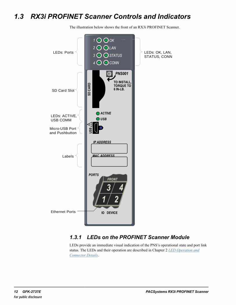
1.3 RX3i PROFINET Scanner Controls and IndicatorsThe illustration below shows the front of an RX3i PROFINET Scanner.
PNS001
ACTIVE
USB
USB
IP ADDRESS
MAC ADDRESS
PORTS
TO INSTALL,TORQUE TO6 IN-LB.
IO DEVICE
FRONT
3 41 2
SD CARD
!
1
2
3
4
OK
LAN
STATUS
CONN
LEDs: OK, LAN, STATUS, CONN
SD Card Slot
LEDs: ACTIVE, USB COMM
Micro-USB Port and Pushbutton
Labels
Ethernet Ports
LEDs: Ports
1.3.1 LEDs on the PROFINET Scanner ModuleLEDs provide an immediate visual indication of the PNS’s operational state and port linkstatus. The LEDs and their operation are described in Chapter 2 LED Operation andConnector Details.
12 GFK-2737E PACSystems RX3i PROFINET ScannerFor public disclosure

1.3.2 SD Card SlotThe SD Card Slot supports an SD or SDHC card. It can be used to transfer the I/O DeviceName to another PROFINET Scanner Module unit without a configuration tool such asProficy Machine Edition.
1.3.3 PushbuttonThe pushbutton adjacent to the USB port is reserved for future use.
1.3.4 USB PortThe USB Port is used for installing new firmware using the Winloader tool.
1.3.5 Ethernet Port ConnectionsFor other options, refer toChapter 4, the section Addingand Configuring an EthernetPort.
Each port on an RX3i PNS operates independently, so devices that operate at differentspeeds and/or duplex modes may be attached to the ports. By default, all ports, includingempty, unconfigured SFP cages, are set for Automatic, which enables auto negotiation forthe widest range of options supported by the port.
Port 1
Port 2
Port 3
Port 4
Bottom of module
Front
Connections to the PROFINET Scanner can be made using standard Cat 5e/6 Ethernetcables. Different devices on the same network can be connected using the multiple portson the RX3i PNS.
Introduction GFK-2737E Manual 13For public disclosure

1.4 PROFINET Operation OverviewAn RX3i PROFINET Scanner (PNS) uses PROFINET communications for dataexchange. The same network can also be used for basic Ethernet communications, but useof a separate Ethernet network and RX3i Ethernet interface is recommended.
A PROFINET network can include three types of devices:
PROFINET I/O Controller A PROFINET I/O Controller collects data from I/Odevices (inputs), and provides data to the devices (outputs). It is associated with one ormore I/O Devices.
PROFINET I/O Device A PROFINET I/O Device is a distributed I/O Device that iscoupled to a PROFINET I/O Controller via PROFINET. In an RX3i system, the RX3iPNS operates as an I/O Device, managing initialization, configuration, andcommunication between the PROFINET controller and the I/O modules.
PROFINET I/O Supervisor An I/O Supervisor can be a programming device, acomputer, or an HMI device. The PROFINET I/O Supervisor is typically used forcommissioning or diagnostics.
1.4.1 PROFINET CommunicationsCommunications on an RX3i PROFINET network use the standard PROFINETcommunications described in this section.
1.4.2 Application RelationshipsBefore a PROFINET I/O Controller can exchange data with a PROFINET I/O Devicesuch as the RX3i PNS, an Application Relationship (connection) must be establishedbetween the devices. The PROFINET I/O Controller automatically sets up the correctnumber and types of Application Relationship and Communication Relationship channels(refer to the following section) based on its Proficy Machine Edition configuration.Usually, only one Application Relationship is established per I/O Device.
1.4.2.1 Communication Relationships within an ApplicationRelationshipWithin each Application Relationship (AR), the PROFINET I/O Controller establishesthe following types of Communication Relationships (CRs):
• Record Data CRs – always the first to be established within an ApplicationRelationship. Record Data Communication Relationships are used for non-real-timetransfers of data records such as startup parameter data, diagnostics data,identification data, and configuration data
• I/O CRs – used for the real-time, cyclic transfer of I/O data• Alarm CR – used for real-time, acyclic transfer of alarms and events
14 GFK-2737E PACSystems RX3i PROFINET ScannerFor public disclosure

The illustration below represents an Application Relationship between a PACSystemsRX3i CPU with an RX3i PNC module and an I/O Device. In this example, the I/O Deviceis an RX3i PNS with RX3i and 90-30 I/O modules, but the same principles apply for allI/O Controllers and I/O Devices.
RX3 i CPU w it h PROFINET Co n t ro llerI /O-Device , su ch asRX3i PROFINET Scanner Record Data Communication Relationship
I/O Data Communication Relationship
Alarm Communication Relationship
Application Relationship
1
23
4
P N S0 0 1
A C T IV EU S B
O K
L A NS T A TU S
C O N N
USB
IP A D D R E S S
M A CA D D R E S S
P O R T S
T O IN S T A L L,T O R Q U E T O6 IN- L B.
IO D E V IC E
F R O N T
3 41 2
SD CARD
!
1
23
4
P N S0 0 1
A C T IV E
U S B
O K
L A NS T A TU S
C O N N
USB
IP A D D R E S S
M A CA D D R E S S
P O R T S
T O IN S T A L L,T O R Q U E T O6 IN-L B .
IO D E V IC E
F R O N T3 41 2
SD CARD
!
1.4.2.2 Application Relationships and PROFINET SystemRedundancyThe RX3i PNS supports a special type of relationship that allows two matchedconnections from two different PROFINET I/O Controllers to exist at the same time.These two connections form a redundant AR set in which one connection serves theActive controlling unit and one serves the Backup unit. Only one of the I/O Controller isthe Active unit at any one time. The I/O Controllers collectively determine whichconnection is Active and which is Backup. I/O Data and Alarms are transferred only tothe Active unit.
I /O-Device , such as RX 3i PROFINET Scanner
Primary AR (I/O Data Alarms)
Backup AR (I/O Data ignored , no Alarms )
I/O Controller #1 I/O Controller #2
Introduction GFK-2737E Manual 15For public disclosure

1.4.3 Types of PROFINET CommunicationsPACSystems PNS modules use two types of PROFINET communication transfers:real-time and non-real-time. The illustration below shows real-time communications assolid lines and non-real-time communications as dashed lines.
RX3i Main Rack with PROFINET Controller
Non -real - time data :
parameters, conf igurat ion,and such
Real -time data :Inputs , Outputs ,
Alarms
1
23
4
P N S0 0 1
A C T IV EU S B
O K
L A NS T A TU S
C O N N
USB
IP A D D R E S S
M A CA D D R E S S
P O R T S
T O IN S T A L L,T O R Q U E T O6 IN-L B.
IO D E V IC E
F R O N T
3 41 2
SD CARD
!1
23
4
P N S0 0 1
A C T IV EU S B
O K
L A NS T A TU S
C O N N
USB
IP A D D R E S S
M A CA D D R E S S
P O R T S
T O IN S T A L L,T O R Q U E T O6 IN-L B .
IO D E V IC E
F R O N T
3 41 2
SD CARD
!
• Real-Time (RT) communication: PROFINET real-time communication is usedfor time-sensitive data. A PROFINET I/O Controller and PROFINET I/O Device usetwo types of real-time communications to exchange data: cyclic communication andacyclic communication:− Real-time Cyclic communication is used to periodically transfer the application’s
input and output data. Cyclic communication occurs each PROFINET I/Oproduction cycle.
− Real-time Acyclic communication is used to transfer non-periodic data such asalarms. Acyclic communication occurs only when needed.
• Non-Real-Time (NRT) communication: PROFINET non-real-timecommunication is used for less time-sensitive data such as configuration,parameterization, diagnostics, and identification data.
1.4.4 Operations of the PROFINET ScannerThe RX3i PNS performs the following operations:
• Consumes PROFINET I/O Device configuration from the PROFINET I/O Controllerover the PROFINET network and applies it to its modules.
• Scans input data from each module it manages and produces that data to thePROFINET I/O Controller.
• Consumes the output data that it receives from the PROFINET I/O Controller andapplies it to each module it manages.
16 GFK-2737E PACSystems RX3i PROFINET ScannerFor public disclosure

1.4.5 I/O ScanningIn the PACSystems RX3i PROFINET network, multiple I/O cycles run asynchronouslyand independently. The example below illustrates typical cycles in a system with an RX3iCPU with a PNC module, and RX3i PNS modules used as I/O Devices. Cycles may bedifferent for third party devices.
�� ��� ���
�� ��� �� �� ��� ��
������ ��
������������� �����������
������������
����������� �������� �
• PROFINET I/O Device Scan: In this example, each PNS scans all of its I/OModules as quickly as possible. The PNS stores the modules’ input data into itsinternal memory. On each PNS output scan, the Scanner writes the output data fromits internal memory to its I/O modules.Third-party devices: The transfer of I/O data between an I/O module and thePROFINET I/O network is device dependent. Refer to the third-party manufacturerdocumentation for specifics for a particular device.
• PROFINET I/O Production Cycle: Each PNC and I/O Device publishes data fromits internal memory onto the network at its scheduled PROFINET production cycle(Note: Production cycles between I/O Controllers and I/O Devices are notsynchronized; each publishes at its configured update rate independently). The PNCpublishes output data received from the RX3i CPU to each I/O Device, and the I/ODevice publishes input data from its memory to the PNC.
• RX3i CPU Sweep: The RX3i CPU Sweep includes both an input scan and anoutput scan. The CPU input scan retrieves the current input data being stored withinthe PNC module. This input data is then available for use by the application logic.After the logic solution, the CPU output scan writes the outputs to the PNC.
1.4.6 Media Redundancy Protocol SupportPROFINET Media Redundancy Protocol (MRP) supports devices configured in a ringtopology. MRP is specified as part of IEC62439 and has been adopted by the PROFINETspecification, which provides for convenient configuration of the ring topology andnecessary parameters. Like PROFINET IO data, Media Redundancy Protocol operationsare not routable between different IP subnets.
Each device within an MRP ring has two physical pathways to the I/O Controller. Toconnect to the ring, each device requires an integrated switch with at least two externalports (ring ports) that support Media Redundancy Protocol. Devices that are notMRP-capable can be connected to a device in the ring (for example, an MRP-capableswitch in the ring), but they should not be in the ring themselves. The redundancycapability offered by the ring topology only extends to the devices on the ring that areMRP-capable and enabled.
Introduction GFK-2737E Manual 17For public disclosure

One of the devices on the ring must be configured as the Media Redundancy Manager(MRM), and all the other devices must be configured as Media Redundancy Clients(MRCs). The PNS can be configured as an MRC. Configuring the PNS as an MRC altershow the Ethernet ports connect to the network. They attempt to indicate their state to theMRM before allowing traffic to flow between the ports and close the ring topologythrough the internal switch. They also send out notifications to the MRM when a port islost. Operation of the PNS is otherwise unchanged.
The MRP configuration is stored in non-volatile storage in the PNS and activatedimmediately upon powering up. Non-volatile storage is updated as part of a connectionwith the I/O Controller. A DCP Reset disables MRP Client operation and updatesnon-volatile storage. The current state of the MRP configuration is provided as part of thePNS’s Input Status Bits which are accessible to user application logic. Refer to Chapter 5,the section,Input Status Bits, for further details.
Fast ring-break detection is not fully functional until all MRP clients have received theirMRP configuration. For a discussion of ring-break detection, refer to the followingsection Bumpless Operation with MRP.
1.4.7 Bumpless Operation with MRPThe RX3i PNS supports bumpless operation with GE Intelligent Platforms PROFINETIO Controllers if specific conditions are met. Bumpless operation means that a singlebreak in an MRP ring will not cause the PROFINET connection to be lost and there is noobserved loss and addition of PROFINET IO Devices while the ring network recovers.
Without bumpless MRP, when a device is lost, it must be re-acquired by the IOController; a typical recovery time is on the order of seconds.
There are two ways an MRM detects a break in the ring:
• a message from an MRC that provides LinkUp/LinkDown detection• a test packet timeout interval
A network using Media Redundancy Protocol recovers from a ring failure within 80milliseconds when running at 100/1000 Mbps full duplex with default Media RedundantManager (MRM) test packet values. Actual failover time depends on the deviceresponsiveness to network disconnection and reconnection, number of devices in the ring,media speed, length of media, and frequency of sending test frames over the network.Network recovery time is shorter with fewer devices, faster media speed, and shortermedia lengths. Third-party devices in the MRP ring may introduce additional networkrecovery time. Network recovery time is limited by the ring participant with the slowestring failure recovery time. Devices that do not provide LinkUp/LinkDown detectionshould be taken into account when calculating network recovery time.
For bumpless network recovery (without disturbing I/O communications to an I/ODevice), the I/O Update Rate for the I/O Device should be configured to be greater than1/3 of the network recovery time. This permits the ring to be disconnected or reconnectedwithout timing out the communication connection between the I/O Device and its I/OController In order to insure correct MRP operation, it is important to connect the correctEthernet ports of the PNS to the MRP ring. The ports connected to the ring must be thesame ports configured as MRP Ring Ports. Failure to connect the configured ports willprevent the PNS from correctly participating in the MRP ring. To assist withconfiguration of the ports during system commissioning, it is recommended that youdisable all device ports that will not be used as ring ports.
18 GFK-2737E PACSystems RX3i PROFINET ScannerFor public disclosure

1.4.8 MRP Operation for I/O Update Rates of 16 ms orgreaterThe RX3i PROFINET I/O Controller supports bumpless operation at 16ms with therequirement that the MRP Manager be configured for an MRP Test Packet Interval andMRP Test Packet Count that is faster than the fastest I/O timeout possible.
For example:Assume the worst case scenario when a ring break occurs immediately after the PNSreceived a test packet and immediately before the PNS was scheduled to receive an I/Opacket. In the case of a 16 ms I/O Update Rate, a timeout will occur after threeconsecutive missed I/O packets, which can occur in slightly over 32 ms. Assuming thatthe Test Packet Interval is configured for 10 ms and the Test Packet Count is configuredfor two, we can detect a ring break in just less than 30 ms. This ring recover scenariowould look like the following timeline.
�������������� ��������
���������
�����������
������������������
����������������
�� ����������������������������������
� ���������������!���"
��������� ��������������������# ��� $� ����� ���
������������� ��
#������������������
%�������������������
In order to ensure a successful ring recovery using the Test Packets at a 16 ms I/O UpdateRate or above, make sure the following statement is true:
Test Packet Interval × (Test Packet Count + 1) < I/O Update Rate × 2
1.4.9 MRP Operation at I/O Update Rates less than 16msThe RX3i PNS implementation of MRP supports LinkUp/LinkDown detection, anoptional part of the MRP standard. This allows an MRC experiencing a network linkfailure or recovery to send LinkUp/LinkDown messages to the MRM immediately. TheMRM can heal the network without needing to wait for multiple test-packet timeouts todetect the failure. This feature allows the network recovery time to be significantlyshorter than the test packet timeout interval because the break is detected immediately.
1.4.9.1 Forcing 100 Mbps to Obtain Bumpless Ring at I/OUpdate Rates of 2, 4 and 8 msThe standard, IEEE 802.3 Clause 40, has a requirement for link detection at 1 Gbps thatcan be as slow as 750 ms, which is too slow to reconfigure a ring before three consecutiveI/O packets are missed.
Introduction GFK-2737E Manual 19For public disclosure

The RX3i PNS uses a fast link detection feature on its non-SFP ports that allows twoRX3i devices connected to each other at 1 Gbps to detect a link break fast enough toperform bumpless I/O recovery at a 2, 4 or 8 ms update rate. If the RX3i PNS isconnected to any other device that does not support fast link detection at 1 Gbps speeds,the RX3i PNS’ MRP ring port can be configured to limit that port to operate at 100 Mbps.This will force the device connected to the RX3i PNS to operate at 100 Mbps which has amuch faster link detection time. See the Adding and Configuring an Ethernet Port in theConfiguration chapter for how to set a port to 100 Mbps.
1.4.10 Minimum I/O rate when Configured in an MRPring
For RX3i PNC operatingspecifications, refer toGFK-2571, PACSystems RX3iPROFINET ControllerManual.For operating specifications ofthe RXi Controller’s embeddedPNC function, refer toGFK-2816, PACSystems RXiICRXICTL000 Distributed I/OController User's Manual.
The minimum I/O rate that is possible for bumpless operation depends on the speed andthe type of physical connection being used for the MRP ring ports. PACSystemsPROFINET I/O Controllers support a specified number of GE Intelligent PlatformsPROFINET IO devices running at or above the minimum I/O Update Rate listed in thetable below.
20 GFK-2737E PACSystems RX3i PROFINET ScannerFor public disclosure

1.4.11 Minimum I/O Rates for Bumpless RX3i PNSRecovery
Connec-tion Type
Minimum IO Update Rate Minimum IO Update Rate
1 Gb/s # of Devices 100 Mb/s # of DevicesFixedCopperPort
2ms 16 2 ms 16
1000Base-LX
16 ms1 63 N/A2 N/A
1000Base-ZX
16 ms1 63 N/A2 N/A
100BaseL-X10
N/A2 N/A 16 ms1 63
1000Base-SX
16 ms1 63 N/A2 N/A
100BaseFX N/A2 N/A 16 ms1 63
1000BaseT 16 ms1 63 16 ms1 631 The 1000BaseT SFPs qualified for use with the RX3i PNS can only detect a ring
break when running at 1 Gb/s at the IEEE 802.3 Clause 40 standard requirementof 750 ms. The Fiber SFPs can only detect a ring break at the SFF-8472 RX_LOSassertion time of 100 ms. In order to do bumpless I/O at a 16 ms I/O Update ratewith these SFPs, the MRM must be configured with a Test Packet Interval of 10ms and a Test Packet Count of 2.
2 These devices operate at a fixed speed and duplex.
1.4.11.1 Third-party PROFINET Devices as MRP ClientsIf 3rd-party PROFINET Devices configured as MRP Clients are in use in the ring,customers can set a minimum I/O update rate to the larger of the options below andexpect I/O to operate bumplessly through ring network recovery:
• Minimum I/O Update Rate configurable in PME that is more than 1/3 the time of theworst-case ring recovery stated by 3rd-party manufacturer, regardless of portsutilized. (For example, if a manufacturer states their worst-case ring recovery is 96ms, then the minimum I/O Update Rate allowed must be greater than 96/3 = 32 ms,therefore select the next available value, 64.)
• 16 ms I/O Update Rate minimum, regardless of ports utilized, and must set MRP TestPacket Interval to 10 ms and MRP Test Packet Count to 2
Introduction GFK-2737E Manual 21For public disclosure

1.5 System LimitsI/O Controllers will have limitations on the system they support. One of these limits is thenumber of PROFINET submodules supported. In the RX3i PNS rack, each power supplyor I/O module is represented by one PROFINET submodule. The RX3i PNS uses four tosix submodules:
• two submodules for basic operation of the PNS module• two built-in port submodules that are always configured• up to two additional port submodules, one for each optional Ethernet port configured
Other limitations, such as the configuration and I/O sizes, are specific to the configurationoptions chosen. Note that not every combination of options is supported in every system.If the configuration uses all slots in every device with a large device count, the memory ofthe I/O Controller system will be a limiting resource.
1.6 Supported Modules, Power Supplies and BackplanesFor a list of modules, power supplies and backplanes that can be used with an RX3iPROFINET Scanner I/O Device, refer to the Important Product Information documentprovided with the firmware version on your PNS module.
22 GFK-2737E PACSystems RX3i PROFINET ScannerFor public disclosure

2 LED Operation and Connector DetailsThis chapter describes:
• LEDs• Ethernet Network Ports• SD Card Slot• USB Port
2.1 Normal Operation of Individual LEDs
2.1.1 OK LED
Green ON
OK
OFF
Not OK
2.1.2 LAN LEDThe LAN LED indicates access to and activity on the Ethernet network. The LAN LEDindicates network packets are being processed by the network interface (not just passingthrough the embedded switch).
Blinking ON
The module’s network interface is active
OFF
No activity
2.1.3 Status LEDThe STATUS LED stays green during normal operation.
Green, ON
Normal Operation
Red, blinking
A MAC address read from nonvolatile memory isinvalid. Ports with invalid MAC addresses remaindisconnected from the Ethernet network.
LED Operation and Connector Details GFK-2737E Manual 23For public disclosure
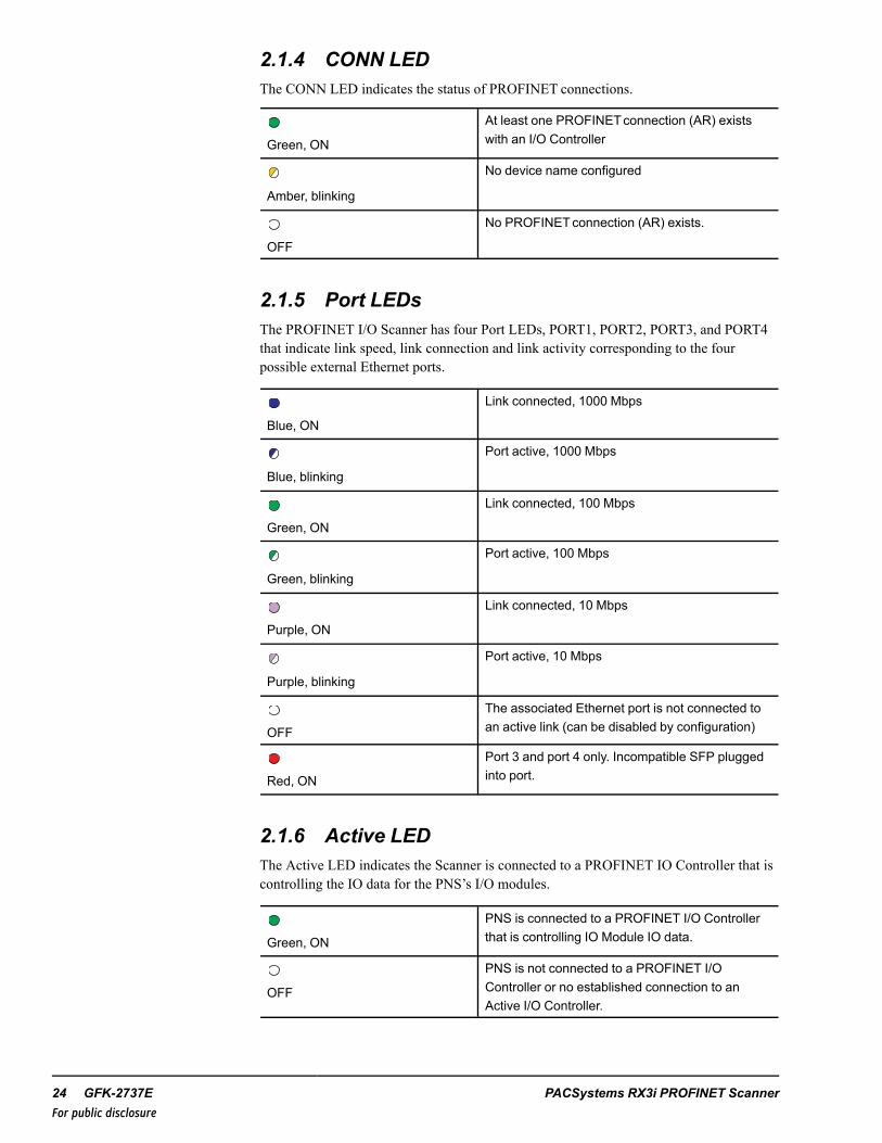
2.1.4 CONN LEDThe CONN LED indicates the status of PROFINET connections.
Green, ON
At least one PROFINETconnection (AR) existswith an I/O Controller
Amber, blinking
No device name configured
OFF
No PROFINETconnection (AR) exists.
2.1.5 Port LEDsThe PROFINET I/O Scanner has four Port LEDs, PORT1, PORT2, PORT3, and PORT4that indicate link speed, link connection and link activity corresponding to the fourpossible external Ethernet ports.
Blue, ON
Link connected, 1000 Mbps
Blue, blinking
Port active, 1000 Mbps
Green, ON
Link connected, 100 Mbps
Green, blinking
Port active, 100 Mbps
Purple, ON
Link connected, 10 Mbps
Purple, blinking
Port active, 10 Mbps
OFF
The associated Ethernet port is not connected toan active link (can be disabled by configuration)
Red, ON
Port 3 and port 4 only. Incompatible SFP pluggedinto port.
2.1.6 Active LEDThe Active LED indicates the Scanner is connected to a PROFINET IO Controller that iscontrolling the IO data for the PNS’s I/O modules.
Green, ON
PNS is connected to a PROFINET I/O Controllerthat is controlling IO Module IO data.
OFF
PNS is not connected to a PROFINET I/OController or no established connection to anActive I/O Controller.
24 GFK-2737E PACSystems RX3i PROFINET ScannerFor public disclosure

2.1.7 USB LED
Green, ON
A USB cable is connected.
Green, blinking
USB port activity
OFF
No USB port activity
2.1.8 Special LED Blink PatternsThe PNS’s LEDs can operate in tandem to indicate fatal error, modulelocation/identification, microprocessor over temperature, and update conditions, asdescribed below. There is also a startup sequence that tracks the startup processing of themodule with the LEDs.
2.1.8.1 Fatal Error CodesWhen the PNS encounters a fatal error, it will blink an error code pattern on the OK LEDwith an Amber color or on the STATUS LED with a Green color. In this mode all LEDsflash Green once to indicate the start of the error code. Next the OK or STATUS LEDblinks a 4-digit decimal error code. The LED first blinks to indicate the most significanterror digit, then after a brief pause blinks again to indicate the next significant error digitand so forth. After another brief pause, all LEDs flash Green again and the error codepattern repeats. Repetitions continue indefinitely until the module is power-cycled.
2.1.8.2 Module IdentificationThe LEDs on a PNS module can be commanded to repeatedly turn ON and OFF in aspecial sequence, to help locate or identify the module:
• First the green LEDs are turned on in the following circular order: OK, LAN,STATUS, CONN, PORT 4, PORT 3, PORT 2, PORT 1. There is a short delaybetween turning on each LED.
• The LEDs are then turned off in the same order. There is a short time delay betweenturning off each LED.
The Module Identification LED Pattern is initiated by the PROFINET DCP IdentifyDevice command. Module Identification can be initiated using the Proficy MachineEdition Discovery Tool by refreshing the device list, double clicking on the RX3i PNSmodule, and clicking the Identify Device button on the PNS properties pop-up window.
LED Operation and Connector Details GFK-2737E Manual 25For public disclosure

2.1.8.3 Microprocessor Over TemperatureIf the maximum threshold temperature for the PNS’s microprocessor is crossed, the PNSgoes into power-saving mode. While the PNS is in an over temperature condition, thefollowing blink patterns are alternated:
• PORT 1, PORT 2, and STATUS LEDs turn on RED for 0.5 seconds (all other LEDsoff)
• Then PORT 3 and PORT 4 LEDs turn on RED for 0.5 seconds (all other LEDs off)
The PNS stays in power-saving mode until the temperature drops to a safer level. Once asafe temperature is reached, the PNS module restarts.
Note Under certain ambient operating temperatures, the PNS may momentarily displaythe over temperature pattern during power up while it is calibrating its thermal protectionfunctions. This indication can be ignored.
2.1.8.4 Firmware UpdateWhile the PNS is in firmware update mode, the OK, LAN, and STATUS LEDs blinkGreen for 0.5 seconds and then off for 0.5 seconds in unison. During firmware updateoperation, the ports are disabled, so all of the PORT LEDs are off and the CONN LED isoff. The USB LED operates normally displaying the condition of the USB port.
2.1.8.5 Internal UpdateSome changes from a firmware update are applied to the system on the next power up.During this internal update process, the STATUS and LAN LEDs blink Green for 0.5seconds and then off for 0.5 seconds in unison. At the completion of the internal updateprocess, the PNS restarts and should power up normally.
26 GFK-2737E PACSystems RX3i PROFINET ScannerFor public disclosure

2.1.8.6 Powerup LED PatternsAt powerup, the LEDs show the patterns described below. The LEDs also blinkdiagnostic patterns for certain operating errors and for module identification. See theSpecial LED Blink Patterns section for a description of the special blink patterns.
Step LED/Blink Pattern Description
1 All LEDs off Initial state
PNS001
ACTIVE
USB
USB
IP ADDRESS
MAC ADDRESS
PORTS
TO INSTALL,TORQUE TO6 IN-LB.
IO DEVICE
FRONT
3 41 2
SD CARD
!
1
2
3
4
OK
LAN
STATUS
CONN
2 STATUS LED solid green Normal operation
OK LED blinks amber withspecial blink code
Fatal initialization or diagnostics Failure;H/W Module Identity Information notavailable
STATUS LED blinks green withspecial blink code
Fatal initialization failure.
OK, LAN, and STATUS LEDsblink green in unison (0.5second ON/ 0.5 second OFF)
Invalid firmware detected or firmwareupdate initiated. Module is waiting forfirmware update. Blink patterncontinues during firmware update. Afterthe automatic update completes, theLAN and STATUS LEDs blink Amberand the module resets, which restartsthe powerup process.
STATUS and LAN LEDs blinkgreen in unison (0.5 secondsON/ 0.5 seconds OFF)
Internal update in process following afirmware update. Unit should completeupdate and restart automatically.
3 LAN and STATUS LED solidgreen
Normal operation
4 OK LED solid green Normal operation. Powerup completed.
Note Under certain ambient operating temperatures, the PROFINET Scanner maymomentarily display the over temperature pattern during power up, while it is calibratingits thermal protection functions. This indication can be ignored. For details, refer to thesection,Microprocessor Over Temperature.
LED Operation and Connector Details GFK-2737E Manual 27For public disclosure

2.2 Ethernet Network PortsThe four external Ethernet ports (two RJ-45 and two SFP Cages) are on the bottom of themodule. The illustration below is a bottom view of the RX3i PNS with its two RJ-45 and2 Small Form-factor Pluggable (SFP) ports.
Port 1
Port 2
Port 3
Port 4
Bottom of module
Front
The RX3i PNS’s two RJ-45 ports provide 10/100/1000 Mbps copper interfaces and twoSFP cages for user-supplied SFP devices, which can support a number of different mediatypes. Refer to SFP Modules for Ethernet Ports in the Installation chapter for additionalinformation about SFPs. The two RJ-45 ports support CAT5e/6 cabling of up to 100m.Each Ethernet port automatically senses the type of network and adjusts speed andconnection parameters. The PROFINET protocol can be sent and received over any or allof the four external ports.
Devices connected to the PROFINET Scanner ports should have EthernetAutonegotiation enabled. The Ethernet ports can be disabled to support requirements suchas IT policies for unused ports. Disabled ports do not establish a link on their Ethernetnetwork. RX3i PNS modules and other participating modules can be connected in a daisychain/line, or star topology. The ports can also be configured to limit their advertisedAutonegotiation setting. This can be used to force a copper interface to establish a link at100 Mbps rather than 1 Gbps to have quicker link change detection during MRPoperation.
Caution
Multiple ports on the Ethernet Interface must not beconnected, directly or indirectly, to the same deviceso as to form a circular network.
Caution
Port disable settings are nonvolatile. If an SFP portis configured as the only enabled port and that SFPis removed, the RX3i Scanner will not be accessibleuntil an SFP is returned to that port.
28 GFK-2737E PACSystems RX3i PROFINET ScannerFor public disclosure

2.3 SD Card SlotThe SD Card Slot, located on the front of the PROFINET Scanner, can be used to transferthe I/O Device Name from a different PROFINET Scanner without the need for aconfiguration tool such as PME to commission the new hardware. A card is not requiredto be present. See Transferring the IO-Device Name with an SD Card in theConfiguration chapter for more details.
Note that when installing an SD Card, the label should face to the left with thewrite-protect (Lock) switch to the bottom. The card should enter easily and click whenfully inserted. The spring action will return the card back slightly from its fully depressedposition. Do not force the card into the slot as that can damage the unit. To release thecard, press the card in again until it clicks, and the spring action will eject the card outenough to easily grab hold of it.
SD and SDHC capacity cards are supported. An SD Card can be formatted as eitherFAT12 or FAT16 per the SD Card standard and an SDHC card should be formatted usingFAT32 per the SD Card standard.
2.4 USB PortThe USB port, located on the front of the PROFINET Scanner, can be used to connect acomputer for firmware updates for the PROFINET Scanner. The USB port accepts astandard USB cable (USB Micro B Male to USB Type A Male, not included). The portmust be set up before using it, as described in the Operations chapter.
Note The USB port is for firmware upgrades only. It is not intended for permanentconnection.
LED Operation and Connector Details GFK-2737E Manual 29For public disclosure

Notes
30 GFK-2737E PACSystems RX3i PROFINET ScannerFor public disclosure

3 InstallationThis chapter describes:
• Module Installation− Backplane Knockout Removal− Module Insertion− Module Removal− Power Requirements
• Replacing PROFINET Scanner Hardware− Method 1 – Using the SD Card− Method 2 – Using the DCP Tool
• SFP Modules for Ethernet Ports− Network Cabling and Connector Types− Network Cabling and Connector Examples
• External Switch VLAN Priority Settings
3.1 Module Installation
3.1.1 Backplane Knockout RemovalThe PNS must be installed in a Universal Backplane such as IC695CHS007, CHS012 orCHS016. The back of the PNS has an exposed heat sink and backplane connector. Beforeinserting the module into the backplane, remove the plastic knockout in the slot where themodule will be placed. The installation slot must match the slot that is selected in themodule’s hardware configuration
0 1 2 3 4 5 6 7 8 9 10 11 12
EXPANSION
TB 1
1
8
Removable plastic for the module’s heat-sink.
Installation GFK-2737E Manual 31For public disclosure

3.1.2 Module InsertionThe PNS can be installed in slot 1 or 2 of a 7, 12, or 16-slot RX3i Universal Backplane,or in slot 6 of a 7-slot RX3i Universal Backplane. The back of the PNS has an exposedheat sink and backplane connector. Before inserting the module into the backplane, theremovable conduction cooling cover must be removed from the backplane.
• RX3i rack power must be turned off. The PNS does notsupport insertion/removal while power is applied to thesystem (hot swap).
• Holding the module firmly, align the module with thecorrect slot and connector.
• Engage the module’s rear pivot hook in the notch onthe top of the backplane (1).
• Swing the module down (2) until the module’sconnector engages the backplane’s backplaneconnector.
• Visually inspect the module to be sure it is properlyseated.
• Secure the bottom of the module to the backplaneusing the machine screws provided with the module(3).
• Tighten the heat sink screw on the front of the modulein the threaded hole in the backplate to 6 in lbs, using aflat-tip screwdriver.
1
2
3
32 GFK-2737E PACSystems RX3i PROFINET ScannerFor public disclosure

3.1.3 Module Removal
• RX3i rack power must be turned off.• Loosen the heat sink screw on the front of the module
to release the heat sink from the backplane’saluminum backplate.
• Loosen the screws at the bottom of the module (1).• Pivot the module upward until its connector is out of
the backplane (2)• Lift the module up and away from the backplane to
disengage the pivot hook (3).
3
2
1
3.1.4 Power RequirementsMore than one power supply may be required to support some configurations. Todetermine the system loading, refer to GFK-2314, the table, Module Load Requirementand total the 3.3 v and 5 v needs of the system.
Installation GFK-2737E Manual 33For public disclosure

3.2 Replacing PROFINET Scanner HardwareIf a PNS module needs to be replaced for any reason, the steps to commission a newhardware module are listed below.
Note If the replacement PNS module has no assigned name (the CONNECT LED isblinking Amber slowly), the network cabling can be plugged back in and the nameassigned over the I/O network.
If there is a possibility of duplicate names existing on the network due to a pre-existingI/O Device name assigned in the replacement module and the name will not be transferredvia the SD Card, the I/O Device Name should be assigned before inserting it into aworking I/O network. The I/O Device Name and IPAddress settings can be updatedoffline (for example, in an office setting).
You should only use the Proficy Machine Edition DCP Tool to store the I/O Device nameto the RX3i PNS’ SD Card and avoid hand-editing I/O Device name files contained onthe RX3i PNS’ SD Card. Storing an illegal name to the RX3i PNS will prevent it fromconnecting to its PROFINET I/O Controller until a valid name is stored.
3.2.1 Method 1 – Using the SD Card1. Remove power from the PNS module. This should be done before network cabling is
removed, especially in the case of fiber connections.2. Remove network cabling from the module.3. Remove the SD Card from the module.4. Remove the module.5. Insert the replacement PNS module.6. Insert the SD Card from Step 3 in the replacement PNS module.7. Connect network cabling to the replacement PNS module.8. Apply power to the replacement PNS module hardware. The I/O Controller will update
any IP address settings automatically when it connects.
3.2.2 Method 2 – Using the DCP ToolAlso see Assign an I/O Device Name in the Configuration chapter
1. Remove power from the PNS module. This should be done before network cabling isremoved, especially in the case of fiber connections.
2. Remove network cabling from the module3. Remove the module.4. Insert the replacement PNS module.5. Connect network cabling to the replacement PNS module.6. Apply power to the replacement PNS module hardware.7. Using the utility PROFINET DCP click on the Refresh Device List command button.8. Highlight the row representing the newly inserted PNS.9. Click on the Edit Device command button and type in the device name.10. Click on the Set Device Name command button.
34 GFK-2737E PACSystems RX3i PROFINET ScannerFor public disclosure

3.3 SFP Modules for Ethernet PortsEach Small Form-factor Pluggable (SFP) cage on the bottom of a PROFINET Scannermodule is capable of accepting a 10/100/1000 Mbps copper SFP, 100 Mbps Single-ModeFiber SFP, 100 Mbps Multi-Mode Fiber SFP, 1000 Mbps Single-Mode Fiber SFP, or 1000Mbps Multi-Mode Fiber SFP device. The RX3i PROFINET Scanner supports the SFPdevices listed below. An SFP type other than those listed below can be configured as aGeneric SFP. The RX3i PROFINET Scanner will attempt to operate with a Generic SFPthat identifies itself as an Ethernet SFP. A substitution alarm is generated if the wrongSFP is inserted, but the Scanner attempts to operate with it. Since SFP types other thanthose listed below have not been validated, correct operation cannot be guaranteed.
Warning
Optical SFPs use an invisible laser to generate afiber-optic signal. Always keep the port covered if acable is not installed. Do not look into the open portif a cable is not installed.
Warning
If the surrounding air operating temperature of thePNS is greater than 40 °C, SFP devices could haveoperating temperatures over 70 °C (158 °F). Underthese conditions, for your safety, do not use barehands to remove an SFP device from the SFP cage.Use protective gloves or a tool (needle-nose pliers) toavoid handling the hot SFP device directly whenremoving the SFP device.
3.3.1 SFP Module Types
SFP Type Wavelength(nm)
Media Type Core Size (μm) ModalBandwidth(MHz –Km)
Distance (m)
100BASE-FX(IC695SPF002)
1300 MMF 62.5 500 2 – 2,000(Full-Duplex) 2 – 400(Half-Duplex)
50 400
50 500
1000BASE-LX(IC695SPF010)
1300 SMF 9 - 2 – 10,000
1000BASE-SX(IC695SPF550)
850 MMF 62.5 160 2 – 220
200 2 – 275
50 400 2 – 500
500 2 – 550
1000BASE-LX 1300 SMF 9 - 2 – 10,000
1000BASE-ZX1 1550 SMF 9 - 2 – 70,000
Installation GFK-2737E Manual 35For public disclosure

SFP Type Wavelength(nm)
Media Type Core Size (μm) ModalBandwidth(MHz –Km)
Distance (m)
10/100/1000BASE-T(IC695SPC100)
- CAT5e/CAT6 - - 100 (maximum)
1 It may be necessary to use a signal attenuator with shorter cable lengths in order to reliably establish a link due to the highpower output of the 1000BASE-ZX SFPs.The Scanner does not distinguish between 1000Base-LX and 1000Base-ZX, so no substitution alarm is generated onmismatches between these two types.
3.3.2 Typical SFP ModulesBelow are images of the two types of Ethernet SFPs. The Single- and Multi-Mode FiberSFPs accept an LC Connector. The Copper SFPs accept an RJ-45 connector.
Fiber Copper
3.3.3 Network Cabling and Connector TypesCopper: up to 100 Meters between Devices
All GE Intelligent Platforms products use RJ-45 connectors for copper connections.Copper cabling and connections are easily available in the general market and supportdistances of up to 100 m.
Multi-Mode Fiber: up to 2 Km between Devices
Multi-Mode Fiber supports two types of connectors, LC and SC. The LC connector isused on SFPs on the RX3i PNC and PNS. The SC connector is used on the VersaMaxPNS. Cables are available with LC-to-LC connectors and LC-to-SC connectors to matchthe different connector formats. Multi-Mode fiber can support distances up to 2 Km at100 Mbps. When using fiber, pay particular attention to the cable connector and cableradius clearance requirements in cabinet planning and layout.
36 GFK-2737E PACSystems RX3i PROFINET ScannerFor public disclosure

LC to LC Fiber Connection LC to SC Fiber
Connection
Single-Mode Fiber: up to 70 Km between Devices
Single-Mode Fiber is supported between SFPs using the LC connector. Single-Mode fibercan support distances up to 70 Km. As with the Multi-mode fiber, pay attention to thecable connector, radius, and minimum length requirements in planning the installation.
LC to LC Fiber Connection
LC to LC Fiber connection
3.3.4 Network Cabling and Connector ExamplesCAT5e/CAT6 (shielded or unshielded) with RJ-45 Connector
Multi-Mode Fiber with LC Connector
Single-Mode Fiber with LC connector
Installation GFK-2737E Manual 37For public disclosure

3.4 External Switch VLAN Priority SettingsIf a system includes external switches, these switches must be configured to match theVLAN Priority groupings listed below for the PNS.
The PROFINET I/O specification indicates the VLAN priorities for each type of Ethernettraffic that originates from a PROFINET I/O Device. VLAN priorities range from 0 to 7,with 7 being the highest.
The switch on an RX3i PNS supports just four traffic classes, giving four levels ofpreference. Incoming traffic without a VLAN priority is assigned to the lowest prioritytraffic class. The table below lists the VLAN priorities, and their corresponding prioritiesin the PNS:
VLANPriority
PROFINETIO-ScannerPriority
Ethernet Traffic Description
7 Highest priority MRP Media Redundancy
6 Second-highestpriority
RT_CLASS_1 Cyclic PROFINET I/O
High Priority RTA_CLASS_1
High-Priority PROFINETAlarms
5 Third-highestpriority
Low Priority RTA_CLASS_1
Low-Priority PROFINETAlarms
4, 3, 2, 1 Lowest priority (reserved) (reserved)
0 IPDCP
Device Discovery andConfiguration
38 GFK-2737E PACSystems RX3i PROFINET ScannerFor public disclosure

4 ConfigurationThis chapter provides general information for configuring an RX3i PNS and its I/Omodules in a PROFINET I/O network.
This chapter discusses the following topics:
• Configuration Overview− Basic Configuration Steps− Configuration Tool
• Adding an RX3i PROFINET Scanner to a LAN− Configuring RX3i PROFINET Scanner− Adding RX3i Modules to a Remote Node
□ Adding a Power Supply□ Adding and Configuring an Ethernet Port□ Configuring Module Parameters□ Configuring Analog Modules that have DIP Switches□ onfiguring Analog Modules that have Jumpers
• Assigning I/O Device Names− Transferring the I/O Device Name with an SD Card
• After the Configuration is Stored to the PROFINET I/O Controller
Configuration GFK-2737E Manual 39For public disclosure

4.1 Configuration OverviewThe RX3i PNS receives its configuration from a PROFINET I/O Controller, which isconfigured by a PROFINET I/O configuration tool. The GSDML files are provided withProficy Machine Edition. For other PROFINET I/O configuration tools, the PNS GSDMLmust be imported. The RX3i PNS GSDML can be obtained by contacting GE IntelligentPlatforms Technical Support.
Note For details on using the Proficy Machine Edition PLC Logic Developerprogrammer to create and download the configuration for an RX3i PROFINET networkand its I/O devices, refer to GFK 2571, PACSystems RX3i PROFINET Controller Manual.
4.1.1 Basic Configuration StepsThe basic configuration steps are:
• Configure a PROFINET I/O Controller and its PROFINET LAN using the I/OController manufacturer’s recommended PROFINET I/O configuration tool.
• Configure the parameters of the PROFINET I/O Controller.• Add I/O Devices to the LAN.
PROFINET Scanners and other types of I/O Devices use GSDML files to describetheir capabilities. The PROFINET I/O configuration tool imports these GSDML filesand incorporates the devices into the configuration.
Note These I/O Devices can be VersaMax or RX3i PROFINET Scanner modules orthird party I/O Devices.
• Configure the parameters of the RX3i PROFINET Scanner.• Configure the communications properties of the PROFINET I/O Controller and RX3i
PROFINET Scanner.• Add RX3i/Series 90-30 modules to the RX3i PROFINET Scanner.• Configure the parameters of the modules.• When the configuration is ready, use a DCP tool to assign a name to the RX3i
PROFINET Scanner so the PROFINET I/O Controller can connect to it and deliverthe configuration.
• Store the configuration data from the configuration tool to the PROFINET I/OController.
4.1.2 Configuration ToolThe configuration tool used to configure the PROFINET LAN containing the PNSmodule must support I/O Devices configured with GSDMLV2.3 files.
40 GFK-2737E PACSystems RX3i PROFINET ScannerFor public disclosure

4.2 Adding an RX3i PROFINET Scanner to a LANUse the PROFINET I/O configuration tool to add a PNS module to the LAN. Thisprocess may include importing the PNS module’s GSDML file. Seven versions of thePNS are available, based on the backplane size and which slot the PNS is to be placed in.They are identical in all regards, except the number of slots available to add IO devicesand the slot the PNS is in. Select the version that corresponds to the backplane to be usedand where the PNS will be inserted. The PNS is fixed when the device is created andcannot be moved. If the PNS is moved to a different slot, a new device must be created inthe configuration.
4.2.1 Configuring an RX3i PROFINET ScannerThe PROFINET I/O Scanner has 32 bits of Status data and 32 bits of Control data. Theseshould be mapped to the I/O Controller’s memory. For definitions of these bits, refer toChapter 5, the section PROFINET Scanner Status and Control Data.
The I/O Controller determines the state of the inputs when the PNS is unable to providethem. This could happen when the PNS is not powered on, not connected to the network,or there is a network or configuration issue such that the I/O Controller cannotcommunicate with the PNS. GE Intelligent Platforms’ I/O Controllers support defaultinginputs to Force Off or Hold Last State values until communication is restored.
The network parameters of a PNS (IPAddress, subnet mask, and gateway) should beconfigured so that each device on the network has a unique IPAddress. The I/OController will configure the network parameters for the PNS during the Connectsequence.
When the network parameters are set with the DCP tool, they will be maintained over apower-cycle while no IO Controller is connected. If an I/O Controller is connected andthe network parameters configured for the PNS do not match the currently retentiveparameters stored on the device (those set using a DCP Tool), then the I/O Controller willassign the configured network parameters to the PNS for immediate use during theconnection process. This will overwrite the retentive values that were set by DCP with thefactory default values for IP, subnet, and gateway, (0.0.0.0/0.0.0.0/0.0.0.0). Note that ifthe PNS is now power-cycled without an I/O Controller connected, the module willpower up with the default network settings because network settings configured by theI/O Controller are not retentive. In order to maintain settings over a power-cycle withoutan I/O Controller connected, the network settings assigned by the I/O Controller mustmatch the network settings configured with the DCP Tool.
The rate of data exchange is usually configured on the PNS in configuration tools. ThePNS supports update rates from 1ms to 512 ms. The correct setting for each device candepend on the dynamics of the equipment being controlled, the network loading on thePROFINET-I/O LAN, and the loading of the I/O Controller. It is possible to have betterperformance at 2 ms, 4 ms or greater periods than at 1 ms depending on the overallsystem requirements, design, and loading. The duration of data indicating very brief statesor conditions should be taken into consideration in choosing the correct setting.
Configuration GFK-2737E Manual 41For public disclosure

4.2.1.1 Media Redundancy ParametersBy default, the PROFINET Scanner is not set up for Media Redundancy. If thePROFINET Scanner will be a Media Redundancy Client, select the module ports that willbe used for Ring Port 1, Ring Port 2 and the MRP Domain. The MRP Domain name isused to assign MRP Clients to the media redundancy manager (MRM) for the networkring. The Domain Name is defined in the PROFINET IO Controller’s Media Redundancytab.
4.2.1.2 System Redundancy ParametersRefer to GFK-2308G or laterfor detailed information onsetting up a Hot StandbyRedundancy system.
The Redundancy tab selects whether or not the PNS is redundantly controlled.
When the PNS supports PROFINET System Redundancy and is configured in an HSBCPU Redundancy system, the Programmer defaults the Redundancy Mode parameter toHSB CPU Redundancy.
When the PNS does not support PROFINET System Redundancy or is not configured inan HSB CPU Redundancy system, the PNS Programmer defaults the Redundancy Modeparameter to None, selecting simplex operation.
To configure a redundancy-capable PNS for simplex operation within an HSB CPURedundancy system, change the Redundancy Mode parameter from HSB CPURedundancy to None.
4.2.1.3 Transfer ListAll redundantly controlled I/O must be included in the CPU’s I/O transfer list. Note thatonce the HSB CPU Redundancy Mode is set, Proficy Machine Edition automaticallyexpands the Primary CPU’s input transfer list to include all of your redundantly controlledPROFINET inputs as you assign reference addresses. Proficy Machine Edition alsoautomatically expands the Primary CPU’s output transfer list to include your redundantlycontrolled PROFINET outputs.
The configuration should be stored to both the Primary and Secondary racks beforeattempting to control any I/O in the RX3i PNS.
4.2.1.4 Changing a Redundant PNS ConfigurationTo make changes to the PNSconfiguration once the systemis running, refer to GFK-2308,and follow the procedureDownload a ModifiedConfiguration to a RedundancySystem – Stopping the Process.
Changes to the device’s configuration on either the Primary while the Secondary isrunning or the Secondary while the Primary is running will cause a Loss of Device I/Ofault on the controller that is being updated. The controller with the changedconfiguration will be prevented from re-connecting as long as a non-matching connectionexists with the device from any controller.
42 GFK-2737E PACSystems RX3i PROFINET ScannerFor public disclosure

4.2.2 Adding RX3i ModulesFor a list of modules, power supplies and backplanes that can be used with an RX3iPROFINET Scanner I/O Device, refer to the important product information documentprovided with the firmware version on your PNS module.
4.2.2.1 Adding a Power SupplySome power supplies occupy two slots in the backplane. When adding a two-slot powersupply to an RX3i Scanner configuration, it should be configured in the left-most slotoccupied by the module, and nothing configured for the other slot. For example, wheninstalling an IC695PSA140 power supply in slots 0 and 1 in the backplane, it isconfigured in slot 0 and nothing is configured in slot 1. Because both slots of a two-slotpower supply must fit within the rack, a two slot power supply cannot be placed in thelast non-expansion slot of a rack.
Adding power supplies to the configuration sets up power supply alarms. Loss of Modulealarms will be triggered if the power supply is configured but not working, or configuredin the wrong subslot. These power supplies have no configurable parameters, but theirpower supply and GSDML details can be viewed by double-clicking on a power supplyor right-clicking and selecting Configure.
4.2.2.2 Adding and Configuring an Ethernet PortSFP modules can be added to the RX3i PNS by selecting the correct SFP module typefrom the available SFP module list and assigning it to Port 3 or Port 4. See the SFPModules for Ethernet Ports in Installation chapter for more details about SFPs.
➢➢ To add an SFP module to a PNS: from the Proficy Machine Edition,right-click the Slot containing the PNS and select Change Submodule List todisplay a dialog box that presents a list of supported SFP modules.
The RX3i Scanner supports setting a port to Automatic (Auto-negotiation enabled), afixed speed, or Disabled. Automatic enables auto-negotiation for the widest range ofoptions supported by the port. Particular speed options limit the auto-negotiation to thatone setting such as limiting a 1 Gbps connection to 100 mbps. The Disabled settingpowers down the port so that it does not establish any link. All ports, including empty,unconfigured SFP cages, are set for Automatic by default.
Configuration GFK-2737E Manual 43For public disclosure

The RX3i Scanner rejects configurations that disable all present ports. This rejectioncauses the Scanner to fail to establish a connection. For example, if no SFP modules arepresent and a configuration is attempted which disables the two built-in RJ-45 ports, thatconfiguration does not connect. A configuration which disables the two built-in RJ-45ports, but has an SFP module configured which is not present also does not connect. Inthis example, once an SFP module is present in the specified port, the configurationbecomes valid and a connection can be established.
Caution
The port delivering the configuration can bedisabled by a new configuration and that settingstored to nonvolatile storage. Be sure to understandthe network topology before disabling Ethernetports.
Caution
Port disable settings are nonvolatile. If an SFP portis configured as the only enabled port and that SFPis removed, the RX3i Scanner will not be accessibleuntil an SFP is returned to that port.
4.2.2.3 Configuring Modules with SubmodulesSome PACSystems RX3i I/O Modules have configurable functionality that must beconfigured prior to operation. Proficy Machine Edition indicates an error on the moduleuntil its configuration has been completed.
To complete the configuration, right click the slot containing the IO Module and selectChange Submodule List. This opens a dialog box that presents a list of submoduleoptions.
44 GFK-2737E PACSystems RX3i PROFINET ScannerFor public disclosure

4.2.2.4 Configuring Modules with Multiple Modes of OperationSome PACSystems RX3i modules have multiple modes of operation that change theappropriate limits for their configuration parameters. For example, an IC695ALG616analog input module supports a different set of A/D Scaling Units when in 4 to 20 mAoperation than when it is in -10 V to +10 Voperation.
These different configuration options are implemented as groups of controls which areactivated by a choice made outside of the group and marked with +/- expander controls.Typically, this choice is directly preceding the first group.
If multiple options are available, only the controls associated with the active choice areused. The other settings are maintained, but are ignored by the module. To preventconfusion, it is recommended that only the active choice be expanded. The state of theexpander control does not affect the choice of active controls. If the active setting iscollapsed and not visible, it is still active and its values are used for the moduleconfiguration.
Configuration GFK-2737E Manual 45For public disclosure

4.2.2.5 Configuring Discrete Modules that Have DIP SwitchesSome PACSystems RX3i discrete output modules have a physical DIP switch thatcontrols their output’s operation when connection to an IO-Controller is lost. A switchselects between Force Off and Hold Last State. This setting applies to all the module’soutputs.
The module’s documentation lists any additional requirements for Hold Last State tooperate correctly. For some modules, field power must be maintained on the PACSystemsbackplane in order for Hold Last State to operate correctly.
If a discrete output or discrete mixed module does not have a switch or an additionalconfiguration option specifying its output’s default action, the hardware default is toForce outputs off.
4.2.2.6 Configuring Modules that have JumpersSome PACSystems RX3i analog modules have jumpers on their terminal strips thatcontrol the operation of their I/O. For example, the IC69xALG220 can operate as a +10vdc to -10 vdc analog input or a 4-20 mA analog input depending on a jumper. TheIC69xALG390 uses a jumper rather than a DIP switch to control Force Off or Hold LastState operation.
Jumper settings are latched when the module is started, so the jumper setting cannot bealtered during operation. The RX3i PNS rack must be power-cycled for the new jumpersetting to be reevaluated or the module must be hot-inserted.
4.2.3 Configuring Module ParametersAfter adding PACSystems RX3i modules to the remote IO-Device, their parameters mustbe configured. For all PACSystems RX3i modules, this includes configuring a set of basicparameters such as reference address. Configuration details for those basic parameters aregiven on the following pages. If the module has no module-specific parameters, a blankgrouping of Module Parameters may be displayed in the Configuration Tool.
46 GFK-2737E PACSystems RX3i PROFINET ScannerFor public disclosure

The RX3i modules listed in the following table require additional configuration beyondthe basic parameters described in this chapter. Refer to GFK–0898, Series 90-30 PLC IOModule Specification; GFK-2314, PACSystems RX3i System Manual,; or the individualmodule datasheet for detailed parameter information.
Catalog # Module Description Datasheet
IC693ALG222 Analog Voltage Input Module – 16 Channel GFK-2654
IC693ALG223 Analog Current Input Module – 16 Channel GFK-2655
IC693ALG392 Analog Current/Voltage Output Module – 8 Channel GFK-2557
IC693ALG442 Analog Module, 4 Inputs / 2 Outputs Current/Voltage GFK-2687
IC694ALG222 Analog Voltage Input Module – 16 Channel GFK-2654
IC694ALG223 Analog Current Input Module – 16 Channel GFK-2655
IC694ALG392 Analog Current/Voltage Output Module – 8 Channel GFK-2557
IC694ALG442 Analog Module, 4 Inputs / 2 Outputs Current/Voltage GFK-2687
IC694PSM001 Power Sync and Measurement Module GFK-2748
IC695ALG112 Isolated Analog Current/Voltage Input Module – 12 Channel GFK-2482
IC695ALG508 Analog Isolated RTD Input Module – 8 Channel GFK-2501
IC695ALG600 Universal Analog Input Module – 8 Channel GFK-2348
IC695ALG616 Analog Current/Voltage Input Module – 16 Channel GFK-2372
IC695ALG626 Analog Current/Voltage Input Module – 16 Channel with HART1 GFK-2372
IC695MDL664 Digital Input Module with Diagnostics – 16-Channel GFK-2590
IC695MDL765 Digital Output Module with Diagnostics – 16 Channel GFK-2591
IC695ALG708 Analog Current/Voltage Output Module – 8 Channel GFK-2373
IC695ALG728 Analog Current/Voltage Output Module – 8 Channel with HART1 GFK-2373
IC695ALG808 Isolated Analog Current/Voltage Output Module – 8 Channel GFK-2481
IC695HSC308 High Speed Counter Module - 8 Counters GFK-2441
1 HARTcommunications is not currently supported with the RX3i PNS
4.2.3.1 RX3i PROFINET Scanner Configuration ValidationSome configuration validation is performed by the RX3i PROFINET Scanner when theconfiguration is delivered to the scanner. The following table indicates the configurationvalidations performed for the indicated modules. If the scanner detects an invalidconfiguration for a given module, the module transitions to module default operation andpoint faults are energized on the assigned I/O.
Configuration GFK-2737E Manual 47For public disclosure

If a module listed below receives an invalid configuration, it rejects the configuration,energizes point faults and blinks its OK LED. The module does not transition to anoperational state, as indicated by the OK LED being On-Solid, until a valid configurationis stored.
Catalog # Rules
IC695MDL664 1. Pulse test diagnostic reporting must be disabled when pulse testing is disabled.2. Open wire and short circuit diagnostic reporting must be disabled when the channel is configured fordual-state input type.3. Short circuit diagnostic reporting must be disabled when the channel is configured for tri-state inputtype.
IC695MDL765 1. Pulse test diagnostic reporting must be disabled when pulse testing is disabled.2. Auto Pulse Normal State and Auto Pulse Default State must not be equal to each other if pulsetesting is enabled.
IC695ALG508IC695ALG600
1. – 5. Same as C695ALG1126. The Lead Resistance Compensation must be set to disabled for RTD 2-wire operation.
IC695ALG112IC695ALG616IC695ALG626
1. The High Scale Value Engineering Units cannot be equal to the Low Scale Value Engineering Units.2. The High Scale Value A/D Units must be greater than the Low Scale Value A/D Units.3. The Alarm Limits must be in order, with the High High Alarm greater than or equal to the High Alarm,which is greater than the Low Alarm, which is greater than or equal to the Low Low Alarm.4. The Alarm Limits must be within the configured Engineering Units plus User Offset range, forexample if the High and Low Engineering Unit Scale values are 10,000 and -10,000 and User Offset is1000, the alarm limit range is +11,000 to -9,0005. The Alarm Deadbands must be set such that the Alarm can be cleared. For example, if theEngineering Units Scale Range is -5 to 5 and the High Alarm is 4, the High Deadband must be less than9 or else it is not possible to reach a value that is low enough to clear the High Alarm.Note that the User Offset modifies the range of Alarms and Alarm Deadbands. The User Offset is added tothe High and Low Engineering Unit Scale Values to set the alarm range limits.
IC695ALG708IC695ALG728
1. The High Scale Value Engineering Units cannot be equal to the Low Scale Value Engineering Units.2. The High Scale Value A/D Units must be greater than the Low Scale Value A/D Units.3. The High Alarm must be greater than the Low Alarm.4. The Alarm Limits must be within the configured Engineering Units minus User Offset range, forexample if the High and Low Engineering Unit Scale values are 10,000 and -10,000 and User Offset is1000, the alarm limit range is +9,000 to -11,000.5. The valid range of Clamp Limits (if enabled) and Default Value is extended slightly beyond the alarmlimits minus User Offset, depending on the configured Range.6. Integer Current: +/- 400 Eng Units (0-20mA +400 Eng Units only) Floating Point Current: +/- 0.4 EngUnits (0-20mA +0.4 Eng Units only) Integer Voltage: +/- 500 Eng Units Floating Point Voltage: +/-0.5Eng Units7. The minimum (slowest) ramp rate is the higher Engineering Unit Scale Value minus the lowerEngineering Unit Scale Value divided by 60,000. Put another way, the minimum ramp rate must be noslower than the full Engineering Units range traversed in 60 seconds.
48 GFK-2737E PACSystems RX3i PROFINET ScannerFor public disclosure

IC695ALG808 1. -7, Same as IC695ALG7081. Open Wire Enable Diagnostic reporting is only valid when the module’s Range Type isVoltage/Current and the Range is set to a Current Range.2. Short Circuit Enable Diagnostic reporting is only valid when the module’s Range Type isVoltage/Current and the Range is set to a Voltage Range.
IC695HSC308 1. The counter High Range value must be greater than the Low Range Value.2. If a counter is configured as Continuous within high/low range or One-shot within high/low range, thePreLoad Value must be within the range.3. If 1ms is selected as the Timebase Units, the Timebase range is 1 to 429496. If Units are 1 uS, therange is 1 to 429496729. If Units are 100 nS, range is 1 to 2147483647.4. To be used as a counter Setpoint output an External Output must be configured as Setpoint(s) on theOutputs Tab.
4.2.3.2 Basic Module ParametersThe module parameters define how the IO-Controller scans and stores the module’s data.The number of address ranges varies by module and submodule. For discrete data, there isa starting address and a length for input data and another starting address and length foroutput data. Analog data can be listed with each analog value as a separate address and alength of one or as a group with the starting address listed and an overall length value.What is available can depend on the Configuration Tool.
Input Data / Output Data: The address in the I/O Controller’s reference memory forthe module’s data.
For PACSystems CPUs: Discrete Data can be added to %G, %I, %Q, %T, and %Mmemory areas. Non-Discrete Data can be added to %AI, %AQ, %R, %W, %G, %T, and%M memory areas.
Length: For discrete modules, the length of the input /output data is fixed and cannot beedited.
Other Data: Some modules have other data areas such as Module Status, ESCP PointStatus, or Digital Filter settings. Refer to GFK-2314, PACSystems RX3i System Manual orthe appropriate User’s Manual for more details about the data of each I/O Module.
4.3 Assigning I/O Device NamesAfter the PROFINET Scanner and other I/O Devices on the LAN have been entered intothe configuration, the Discovery and Configuration Protocol (DCP) tool must be used toassign a name to each I/O Device. The name of each device on the LAN must match thehardware configuration in the I/O Controller. This step is required before downloading theconfiguration from the PROFINET IO Controller, or the PROFINET IO Controller willbe unable to connect to the devices and deliver the device’s configuration.
The DCP tool must be connected directly to the PROFINET IO LAN. The DCP toolallows you to display an identification pattern on an I/O Device. This can be helpful todistinguish devices apart when all are at factory default settings.
The DCP tool supports issuing a reset command to an I/O Device. A reset clears thedevice name and sets other nonvolatile settings such as IP, subnet, and gateway to thefactory defaults. A Reset to Factory DCP command also clears all Ethernet port settingssuch as port disabling. This defaults all ports to Enabled with Auto-negotiation on.
Configuration GFK-2737E Manual 49For public disclosure

4.3.1 Transferring the I/O Device Name with an SDCardTo allow replacement hardware to be commissioned without requiring a DCP Tool, theI/O Device Name can be written to an SD Card and then transferred to replacementhardware via the SD Card.
To write the I/O Device Name to an SD Card, the SD Card must be inserted when theDCP Tool assigns an I/O Device Name to the PROFINET Scanner. An assignment of anI/O Device Name using a DCP Tool writes that name to both the SD Card and thenon-volatile storage in the PROFINET Scanner. If the card is removed, the PROFINETScanner maintains its name from its non-volatile storage.
If a PROFINET Scanner is powered up with an SD Card inserted that is programmed witha valid, non-blank I/O Device Name, that PROFINET Scanner will learn the name on theSD Card and update its non-volatile storage with that name. An SD Card without a name(such as a new, un-programmed SD Card) will not affect the PROFINET Scanner atpower up. The PROFINET Scanner will power up and use the I/O Device Name settingspresent in its non-volatile storage.
If an SD Card is present when a DCP Reset to Factory command is issued from the DCPTool, the I/O Device Name on the SD Card will be erased. The DCP Reset to Factorycommand is a method to remove an I/O Device Name from an SD Card.
4.4 After the Configuration is Stored to the I/O ControllerFor complete instructions, refer to the documentation for the I/O Controller and thePROFINET I/O configuration tool.
After successfully processing and applying its configuration data, the I/O Controllertransfers the configuration for remote I/O Devices over the PROFINET network.
An I/O Controller delivers configuration to an I/O Device when it establishes aconnection with the I/O Device. If all connections are lost, the I/O Device retains the mostrecent configuration received since it was last powered up. If a module has not beenconfigured since being powered up, it remains in its hardware default condition. When theconnection(s) are re-established and a configuration is sent to the I/O Device, and theconfiguration of a module has changed, the I/O Device applies the new configuration.
If there are differences between the expected, configured modules and the actual modulespresent in the PNS rack when a connection is established, the PROFINET Scannerindicates differences back to the I/O Controller. Refer to Chapter 6, Diagnostics for moredetail.
50 GFK-2737E PACSystems RX3i PROFINET ScannerFor public disclosure

5 OperationsThis chapter describes:
• Powerup• I/O Scanning• Hot Swap of I/O Modules• Firmware Updates
5.1 PowerupWhen power is applied to the PNS module, it loads a firmware image. During thepowerup process, the module runs diagnostics and initializes its hardware components.
After completing powerup sequence, the OK LED changes from being off to solid ongreen. If a fatal error occurs during powerup, the amber OK LED blinks a unique patternindicating the nature of the failure.
If the module encounters a hardware failure, invalid firmware image, or the powerupdiagnostics fail, the module will not become operational or may enter firmware updatemode. Cycling power to the module may restore operation. See Fatal Error Handling inthe Diagnostics chapter for more details.
Nonvolatile settings such as the PROFINET Device Name, Ethernet networkconfiguration, and Ethernet Port disable settings are activated before a PROFINETconnection is allowed.
Operations GFK-2737E Manual 51For public disclosure

5.2 I/O Scanning
5.2.1 PROFINET Scanner Status and Control DataThe RX3i PNS provides 32 bits of input status data and receives 32 bits of output controldata. The application program in the I/O Controller system can monitor the input statusbits for the PNS module. The output control bits are reserved for future use and have nofunction at this time.
5.2.1.1 Output Control BitsThe PNS module’s 32 bits of control output are reserved for future use.
5.2.1.2 Input Status BitsThe PNS module’s 32 bits of input status provide information about the scanner. Allstatus bits are active high
Status Bits Name Description
1 Module OK Indicates the health of the module. A value of 0 indicates the module is poweringup or has failed. A value of 1 indicates the module is functioning properly.
2 Reserved Set to 0
3 Port1 Link Up 1 = port is connected to another device and is communicating.0 = port is not connected to another device, or the port has some sort of errorpreventing communications.
4 Port2 Link Up
5 Port3 Link Up
6 Port4 Link Up
7–10 Reserved Set to 0
11 MRP Enabled Indicates whether MRP has been enabled or not. A value of 0 indicates that MRPis not enabled. A value of 1 indicates that MRP is enabled.
12 MRP Role Indicates the MRP role the PNS is operating as when MRP is enabled. A value of0 indicates that the PNS is currently an MRP Client. A value of 1 indicates that thePNS is currently an MRP Manager, however the PNS does not currently supportMRP Manager configuration. If MRP is not enabled, then this bit will be set tozero.
13–32 Reserved Set to 0
5.2.2 Data CoherencyThe RX3i PNS provides coherency at a submodule basis only. This means that outputdata from a single I/O Controller for multiple modules in the PNS rack might not beapplied by the PNS during the same output scan. Likewise, input data from all modulesread in a single PNS input scan may not be produced by the PNS during the samePROFINET I/O cycle.
52 GFK-2737E PACSystems RX3i PROFINET ScannerFor public disclosure

5.2.3 Sampling RateThe PROFINET Device Update Rate should be taken into consideration with regard toI/O devices in a Scanner rack. I/O data that changes quickly, such as status bits thatrepresent an event in a module and are only set for one scan of the module, may bemissed if the update period spans multiple scans of the module. In some cases, otherfunctionality may be utilized to capture momentary events. For example, High-speedCounter Over Range, Under Range, Overflow, and Underflow status conditions can belatched by configuring an unused counter to mirror the operating counter and assigningthe event condition as a strobe source. The corresponding strobe status and acknowledgebits may be used to monitor and acknowledge the condition.
5.2.4 Differences From Main Rack (CPU)Some CPU operations are not supported or exhibit different behavior than when used withI/O modules in a CPU rack.
5.2.4.1 InterruptsInterrupts are not supported for I/O modules in a PNS rack. Service Requests that disable,enable, suspend, or resume interrupts have no effect. Interrupt driven Logic blocks cannotbe used with I/O modules in a PNS rack, and interrupt status bits should be ignored.
5.2.4.2 Do I/O and Suspend I/ODo I/O and Suspend I/O operations are limited to updating or suspending the databetween the CPU and PNC. The PROFINET I/O scan is not altered (that is, DO_IO datais not exchanged with the PNS any faster than the PROFINET update rate allows).
5.2.5 Output ControlIf an output module has not been configured since being powered up, it remains in itshardware default condition. If an output module has been configured, the configurationwill specify the output action when communication with the I/O Controller is lost. This istypically one of the following:
• force to the zero state• default to a specified value, or• hold the last given value.
5.2.5.1 Simplex ConnectionsFor simplex PROFINET connections (one I/O Controller connection to the RX3i PNS),communications with the I/O Controller are lost when no message has been received fromthe I/O Controller in a number of I/O Update periods (typically three).
5.2.5.2 Redundancy ConnectionsFor PROFINET system redundancy connections, the configured output action is appliedimmediately when the controlling Primary connection is lost and no matching Backupconnection is established. A Primary connection is lost if no message is received from thePrimary I/O Controller within a number of I/O Update periods. This is similar to simplexoperation because outputs are only controlled only over a Primary connection inPROFINET system redundancy.
Operations GFK-2737E Manual 53For public disclosure

If the Primary connection is lost in PROFINET system redundancy but a matchingBackup connection exists, outputs are held at their last given value for a period of time toallow the Backup connection to be switched into the Primary role. The period allowed iscalculated by the configuration tool. (Proficy Machine Edition uses the CPU sweep rate,I/O Update Rate, network loading, and values from the GSDML to generate this value). Ifthe Backup connection does not switch to Primary within this period, the RX3i PNSterminates the connection and follows the rules for when no connections exist. If theBackup connection is lost during this period, outputs immediately follow the rules forwhen no connections exist.
5.3 Hot Swap of I/O ModulesIf a module is hot extracted (removed with power applied to the system), the PNS detectsthe removal and generates a PROFINET Pull Alarm. When the PNS is connected to aPACSystems I/O Controller, the Pull Alarm is reported as a Loss of I/O Module fault andall point faults for the missing module have the Fault Contact on.
When a module is hot inserted, the PNS detects the insertion and determines whether theconfiguration expects the module to be present or not.
• If the module is not present in the configuration, no alarm or fault is generated. Themodule remains idle at its default state.
• If a module is inserted while the PNS has an established PROFINET connection andthe module does not match the configured module, including any hardware settingsuch as a DIP Switch position, a PROFINET Plug Wrong Submodule alarm isgenerated. This appears as a System Configuration Mismatch PLC Fault in RX3isystems. Fault Contacts for the module remain in the Fault (on) state.
• If a module is inserted while the PNS has an established PROFINET connection andthe module matches the configured module, a PROFINET Plug Alarm is generated.This appears as an Addition of I/O Module I/O Fault in RX3i systems. The module isconfigured using the established PROFINET connection and once the I/O module isready, I/O will start scanning and point fault contacts will transition to reflect anychange in the state of the I/O.
Operation must continue to obey PACSystems Hot Insertion and Removal requirementsas documented in GFK-2314, PACSystems RX3i System. This mostly governs the timingrequirements for physically seating a module.
Note The PNS module should not be installed or removed while power is applied to thesystem. System power must be removed before installing or removing the module.
54 GFK-2737E PACSystems RX3i PROFINET ScannerFor public disclosure

5.4 Firmware Updates
Note The RX3i PNS does not prevent initiation of firmware update when it is activelyconnected to an I/O Controller. When the PNS enters firmware update mode, the PNS andits modules go to their I/O default modes. During the update, the PNS does not drivemodule outputs or send inputs to the I/O Controller. When the firmware update iscompleted and the PNS is rebooted, its previous connections are re-established andcontrol resumes.
Refer to chapter 2, the section,Powerup LED Patterns.
The PNS enters firmware update mode when commanded to do so from the Winloaderupdate utility, or if a firmware component is corrupted or invalid. In firmware updatemode, the PNS module blinks its LEDs in a special pattern as described previously, andits Ethernet ports are not operational.
If the PNS has experienced a fatal error, the module goes to an LED blink-code errorcondition and does not communicate with Winloader, causing Winloader to return atimeout failure indication. The module must be power-cycled before reattempting theupdate.
5.5 Installing the USB Port DriverThe USB port is only used for firmware updates. USB driver files are provided as part ofupgrade packages compatible with the PNS.
With the provided installation files accessible on either a local or network drive, connectthe computer’s USB port to the PNS module’s USB port. When requested, direct theinstallation to the proper location of the installation files.
The serial port name is COM followed by the next available number from 1 to 256. Afterthe computer assigns the USB port a COM port number, that computer uses the sameCOM port number each time it connects to that PNS module.
Note When connecting the USB cable to the PNS, you may receive a warning forinstalling a driver that has not passed Windows Logo testing. This warning should beignored. Because each PNS has a different serial number, the operating system recognizeseach driver installation as different.
Operations GFK-2737E Manual 55For public disclosure

Notes
56 GFK-2737E PACSystems RX3i PROFINET ScannerFor public disclosure

6 DiagnosticsThis chapter describes:
• Configuration Faults• Version Information• Fatal Error Handling• Connection Troubleshooting
6.1 Configuration FaultsIf there are differences between the expected, configured modules and the actual modulespresent in the PNS rack, in the expected slots, when a connection is established, thePROFINET Scanner indicates differences back to the I/O Controller.
• If a module is configured, but is not present or operational in the rack, thePROFINET Scanner indicates there is no module. When used with a PACSystemsPROFINET I/O Controller, a Loss of Module fault is reported and all point faults forthe missing module have the Fault Contact on.
• If a module is configured but does not match the module present, the PNS reports themodule is wrong. When used with a PACSystems PROFINET I/O Controller, aSystem Configuration Mismatch fault is reported and all point faults for the modulehave the Fault Contact on.
• If the module configured is correct, but the module has submodule options that relateto a DIP Switch setting on the hardware and the DIP Switch does not match theconfiguration, the PNS reports the module is wrong. When used with a PACSystemsPROFINET I/O Controller, a System Configuration Mismatch fault is reported and allpoint faults for the module have the Fault Contact on.
• If the actual module correctly matches the configured module, but the configurationfor the module is unacceptable, the module rejects the configuration and energizespoint faults until the configuration is corrected. Many modules blink their OK LEDwhen they reject the configuration. Chapter 4, the section RX3i PROFINET ScannerConfiguration Validation specifies the rules different modules use to validate theirconfiguration.
• If an SFP module is configured but an incorrect, supported SFP is present, the PNSwill allow the present SFP to become operational and issue a substitution alarm. TheSFP module operates fully as if no difference was detected. When used with aPACSystems PROFINET I/O Controller, a Valid Module Substitution fault isreported.
• If a module is installed but not included in the configuration, no problem is reported.The module is ignored by the PROFINET Scanner and defaults itself.
• If an SFP is installed but not included in the configuration, default operation isenabled and active.
Diagnostics GFK-2737E Manual 57For public disclosure

6.2 Version InformationThe RX3i PROFINET Scanner supports the standard PROFINET Identification andMaintenance (I&M) functions. I&M0 Revision information is returned for the PNS slotwith the information for the PROFINET Scanner.
Please consult the documentation for your IO-Controller and configuration tool for howto access I&M data. For PACSystems PROFINET I/O Controllers, this is available underthe Explore PROFINET Networks option in Proficy Machine Edition (for details, refer tothis topic in the applicable PROFINET Controller user’s manual).
6.3 Fatal Error HandlingAny failures that occur during powerup or firmware update mode are considered fatalerrors. This includes faults detected on non-critical devices such as the USB port. Aftersuccessful powerup of the PROFINET Scanner, only catastrophic errors are treated asfatal. When a fatal error occurs, the PROFINET scanner blinks an error code on its LEDs(refer to the chapter LED Operation and Connector Details the section,Fatal ErrorCodes.
Certain conditions can prevent the module from powering up and becoming operationalor entering firmware update mode:
Problem Indication ActionHardware failure • All LEDs off and the module is
unresponsive, or• The STATUS LED is solid
Green and is the only LED thatis on.
Return the module to GEIntelligent PlatformsInvalid firmware
Power-updiagnostics/hard-ware initializationsfail that areconsidered fatal
LED Fatal Error blink code Note the blink code andcontact Customer Service
Catastrophic errorduring operation
LED Fatal Error blink code Note the blink code andcontact Customer Service
58 GFK-2737E PACSystems RX3i PROFINET ScannerFor public disclosure

6.4 Connection TroubleshootingA PROFINET I/O Device can be challenging to troubleshoot if a connection to the I/OController will not establish. Below are some suggestions of possible things to consider:
• Verify the network cabling. Scan the network using both the DCP and ExplorePROFINET Networks tools in Proficy Machine Edition. The I/O Controller and I/Odevices should appear in both tools.
• Verify the spelling of an I/O Device name in the DCP return value from the I/ODevice versus the I/O Device name in the I/O Controller configuration. Verify theI/O Controller configuration matches the configuration active in the I/O Controller.
• Simplify the configuration. Extra, unconfigured modules are generally not an error inPROFINET, so a simpler configuration could connect.
• Invalid configurations could be rejected. For example, disabling all Ethernet portswould lead to significant problems, so the connection with such a configuration isrejected outright. Simplifying the configuration back to defaults can help isolateproblem areas and settings.
• PROFINET configuration occurs using the Ethernet IP settings. If an I/O Devicecannot be PINGed from the I/O Controller’s network location, the problems are morelikely in the network or the I/O Device’s DCP settings (i.e. the device has anincorrect name or no IP address) than the I/O Device configuration.
• Verify the MRP Ring ports selected. If MRP is configured to use Ethernet ports thatare not available, then the connection will fail. This may be an MRP Ring portconfigured for a removable port (SFP) that is not present, or an MRP Ring portconfigured for a removable port (SFP) that is malfunctioning. Disabling MRP Clientduring debugging may help identify SFP problems.
Diagnostics GFK-2737E Manual 59For public disclosure

Notes
60 GFK-2737E PACSystems RX3i PROFINET ScannerFor public disclosure

Appendix A PROFINET SpecificationsRelease 2.00 of the RX3i PROFINET I/O Scanner supports PROFINET v2.3 Class A I/ODevice with the clarifications listed below. For version-specific updates, refer to theImportant Product Information document provided with your module.
PROFINET Protocol SupportRTC – Real time Cyclic Protocol: RT_CLASS_1DCP – Discovery and Configuration ProtocolCL-RPC – Connectionless Remote Procedure CallLLDP – Link Layer Discovery Protocol – transmission onlyMRP – Media Redundancy Protocol – Client only
Technical DataAPI: Single API (0) used.
Number of ApplicationRelations supported:
2 (1 backup and 1 primary forming a redundant-AR set or1 simplex)
Maximum length of cyclicinput data:
1440 bytes
Maximum length of outputdata:
1440 bytes
Alarm Types: Pull, Plug, PlugWrong
DCP: Get/Set/Identify supported. Only All and Name Of Stationfilters supported
Identification &Maintenance:
I&M Data (I&M0 only)
Context Management: by CL-RPC
Minimum cycle time: 1 ms
Ethernet rate: 100/1000 Mbit/s full duplex with auto-negotiation
Appendix A PROFINET Specifications GFK-2737E Manual 61For public disclosure

LimitationsThe following features are not supported in release 2.20.
PACSystems FeaturesAlarmsCommand Feedback dataCommReq commands to I/O ModulesAlarms on Hot Swap of SFP modulesFirmware update of I/O ModulesInterrupts from I/O ModulesVersion information on I/O Modules
PROFINET FeaturesAutoconfigurationConfigure In RunDCP Hello serviceDHCPDiagnostic AlarmsDNS (Domain Name Service protocol)FastStartUpIRT (Isochronous Real Time Protocol)Multicast communicationPROFIenergy ProfilePROFIsafe ProfilePROFINET CBAPTCP (Precision Transparent Clock Protocol)RT over UDPShared I/O deviceSNMP (Simple Network Management Protocol)Substitute DataSupervisor-AR
Only one Input-CR and one Output-CR are supported per AR.
62 GFK-2737E PACSystems RX3i PROFINET ScannerFor public disclosure

IndexAActive LED 24Alarm CR 14Application Relationship (AR) 14
BBackplane Knockout 31
CCommunication Relationships (CR) 14Configuration 39Faults 57Overview 40Storing 50Validation 47
CONN LED 24Connection troubleshooting 59Controls and Indicators 12
DDevice namesAssigning 49transferring 50
Diagnostics 57Discovery and Configuration protocol (DCP) 49
EEthernet Network Ports 28Explore PROFINET Networks 58
FFatal error handling 58LED operation 25
FaultsConfiguration 57Fatal error handling 58
Firmware updates 55LED operation 26
Forcing 100 Mbps to Obtain Bumpless Ring atI/O Update Rates of 2, 4 and 8 ms 19, 28, 43
HHeat sink 31Hot swapI/O modules 54
II/O CR 14I/O Device namesAssigning 49
I/O Scanning 17Input Status BitsRX3i PROFINET Scanner 52
Installation 31replacing PROFINET Scanner hardware 34
Interrupts 53IP addresses 11
LLAN LED 23LED patternsMicroprocessor over temperature 26Module identification 25powerup 27
LEDsNormal Operation 23Special blink patterns 25
LimitsSystem 11, 22
MMAC Addresses 11Media Redundancy Protocol 17Bumpless operation 18configuring 42Minimum I/O rates for bumpless recovery 21
Modules, Power Supplies and Backplanes 22
OOK LED 23Operating Temperature Range 11Operation Overview 14Output Control 53Output Control BitsRX3i PROFINET Scanner 52
PPort Connectors 11, 13Port LEDs 24Power Requirements 11, 33Powerup and Restart 51Powerup LED Patterns 27PROFINET Communications 14Non-Real-Time (NRT) communication 16
PROFINET Specifications 61PROFINET Support 11, 61Pull Alarm 54
RRecord Data CR 14
GFK-2737E Index 63For public disclosure

RedundancyHot Standby ARs 15Media Redundancy Protocol 17
Replacing PROFINET Scanner hardware 34RX3i modulesadding 43
RX3i PROFINET Scanner 10Configuring 41Specifications 11
SSampling Rate 53SFP modules 28, 35Special Blink Patterns 25Specifications 61Status LED 23Supported Modules, Power Supplies andBackplanes 22System Limits 11, 22
TTechnical Support 5TiimingI/O scanning 17
Transferring an I/O device nameusing the DCP tool 34using the SD card 34, 50
UUniversal backplanes 31USB LED 23–25USB port 29driver 55
VVersion information 58VLAN Priority Settings 38
64 PACSystems RX3i PROFINET ScannerFor public disclosure


GE Intelligent Platforms1-800-433-26821-434-978-5100www.ge-ip.com
GFK-2737E For public disclosure