pacsystems* ic695cpl410 rx3i 1.2ghz 64mb rackless cpu w ... · flt on red plc is in stop/faulted...
TRANSCRIPT

GE Automation & Controls
For Public Disclosure
Programmable Control Products
PACSystems* IC695CPL410 RX3i 1.2GHz 64MB Rackless CPU w/Linux Quick Start Guide GFK-3053
July 2018


i IC695CPL410 Rackless CPU w/Linux Quick Start Guide GFK-3053
Contents 1. User Features........................................................................................................... 1
1.1. Switches ........................................................................................................... 5 1.2. Displays and Indicators (LEDs) ......................................................................... 5 1.3. USB Ports ......................................................................................................... 8 1.4. Front-Panel Ethernet Ports ............................................................................... 8 1.5. Serial COM Port ..............................................................................................10 1.6. Video Display Port ...........................................................................................10 1.7. Linux Port ........................................................................................................10 1.8. Energy Pack Connector ...................................................................................11 1.9. Input Power Connector ....................................................................................11 1.10. Removable Data Storage Device (RDSD) ........................................................11
2. Hardware Installation .......................................................................................... 12 2.1. Initial Checks ...................................................................................................12 2.2. Installation .......................................................................................................12 2.3. Installation in Hazardous Areas .......................................................................14 2.4. Connect to Power Supply ................................................................................15 2.5. Grounding ........................................................................................................16
3. Module Start-up .................................................................................................... 17 3.1. You Will Need: .................................................................................................17 3.2. Basic Start-up Steps: .......................................................................................18
4. CPL410 PLC Configuration................................................................................... 19 4.1. Backwards Compatibility ..................................................................................19 4.2. PROFINET Controller Configuration ................................................................19 4.3. Redundancy Configuration ..............................................................................20
5. CPL410 Linux ......................................................................................................... 21 5.1. Start Linux .......................................................................................................21 5.2. Remote Login ..................................................................................................21 5.3. Network configuration ......................................................................................23 5.4. Linux Software .................................................................................................24 5.5. CPL410 File Exchange ....................................................................................27 5.6. Sample Web Page ...........................................................................................27 5.7. Data Exchange with PLC - OPC-UA ................................................................30 5.8. Factory Reset ..................................................................................................34 5.9. SQLite Demonstration Database .....................................................................35
6. Additional Information ........................................................................................ 38


GFK-3053 IC695CPL410 Rackless CPU w/Linux Quick Start Guide 1
1. User Features
Figure 1: CPL410 Features at a Glance
The PACSystems* RX3i CPL410, part of GE’s Industrial Internet Control System, is a controller with integrated Linux. It augments real-time deterministic control with an Ubuntu 16.04 Server Linux, open to modifications and enhancements. With this product, customers can implement custom data processing like Edge- or Cloud-based analytics, Cloud storage, WEB visualization and many more. Full Linux root access is granted, allowing the user to enhance CPL410 in a virtually limitless manner, thereby achieving outcomes that today’s businesses require. Use cloud services which best fit your application; install freely-available data visualization tools and analytics programs or use professional software to turn GE´s CPL410 into your custom controller. CPL410 can be programmed to dynamically influence business outcomes, generate new forms of revenue, and improve profitability.

2 July 2018 GFK-3053
Figure 2 illustrates the principle of hardware and software separation on CPL410 (only major HW components shown).
Figure 2: Hardware/Software Separation
Features: • The stand-alone CPL410 uses a 1.2GHz quad-core microprocessor and real-time
hypervisor technology to run real time deterministic control applications concurrently with an Ubuntu Server Linux 16.04 LTS. Hypervisor technology ensures the separation of the real-time and Linux world security; performance-wise, each is independent of the other. OPC-UA industry standard protocol allows data exchange between the controls and the Linux application.
• A built-in RX3i PLC: o User may program in Ladder Diagram, Structured Text, Function Block
Diagram, or C. o Contains 64Mbytes of configurable data and program memory. o Supports auto-located Symbolic Variables that can use any amount of user
memory. o Reference table sizes include 32k bits for discrete %I and %Q and up to 32k
words each for analog %AI and %AQ. Bulk memory (%W) also supported for data exchanges. - Supports up to 512 program blocks. Maximum size for a block is 128KB. - For a more extensive feature list of the RX3i PLC please consult the
PACSystems Reference Manual GFK2222
• A built in Ubuntu 16.04 Server LTS:

GFK-3053 IC695CPL410 Rackless CPU w/Linux Quick Start Guide 3
o Ubuntu is a free, open source operating system. It is very well known and in widespread use. For CPL410 the Ubuntu Server variant has been selected as it includes multiple network utilities and protocols and has a smaller footprint than the Desktop version. In contrast to the latter, the Server version offers a purely text-based user interface, unlike the graphical desktop. LTS (Long Term Support) indicates availability of updates till 2021. Running Ubuntu Server concurrently with the real-time control applications allows the CPL410 to rapidly leverage external data. External monitoring may be used to analyze and optimize entire business operations. The analysis can then be used to dynamically adjust real-time industrial controls to align with changing business objectives in today’s Industrial Internet age.
• Supports four independent 10/100/1000 Ethernet LANs. The three Ethernet ports located on the front panel, as shown in Figure 1, are exclusively assigned to the RX3i PLC: LAN1 attaches via the upper, dedicated RJ 45 connector. LAN2 and LAN3 each attach via a pair of internally-switched RJ 45 connectors. The fourth LAN, labeled ETH, is located on the underside (Figure 3), and is exclusively used for Linux connectivity.
• The embedded communications interface has dedicated processing capability, which permits the CPU to independently support LAN1 and LAN2 with: o up to 48 simultaneous SRTP Server connections; o up to 16 simultaneous Modbus/TCP Server connections; o 32 Clients are permitted; each may be SRTP or Modbus/TCP. o OPC UA Server with support for up to 5 concurrent sessions with up to
10 concurrent variable subscriptions and up to 12,500 variables; o up to 255 simultaneous Class 1 Ethernet Global Data (EGD) exchanges.
• The embedded PLC may use one or both Ethernet LAN2 ports to support the embedded PROFINET I/O Controller. PROFINET supports up to 32 I/O devices with update rates of 1 – 512ms. I/O device update rates of 8ms and faster are possible with 16 or fewer devices. Update rates of 16ms and higher result whenever more than 16 devices are configured.
• Media Redundancy Protocol (MRP) allows the CPL410 RX3i PLC to participate in a PROFINET I/O network with MRP ring technology. This eliminates the I/O network as a single point of failure. The RX3i PLC may be used as either a Media Redundancy Manager or Media Redundancy Client.

4 July 2018 GFK-3053
• The CPL410 RX3i PLC supports Hot Standby Redundancy with PROFINET IO. In this configuration, LAN3 is used as a high-speed data synchronization link between the two redundant CPUs. Only the Primary and Secondary CPUs may be attached to LAN3. Two OLED menu items support Redundancy operation: RDN Info and RDN Command. The RACT and RBOK LEDs reflect the status of the Redundant CPUs.
• The CPL410 RX3i PLC supports two independent Redundant IP addresses, one for LAN1 and one for LAN2. LAN2 Redundant IP is supported when configured for Ethernet mode only. Redundant IP is supported by the SRTP Server, Modbus TCP Server, and EGD protocols. It is not possible to use Redundant IP with the OPC UA Server or with the Ethernet firmware update web page.
• The real-time part of CPL410 is secure by design, incorporating technologies such as Trusted Platform Modules, secure boot, and encrypted firmware updates. It is neither accessible or modifiable by customers nor intruders, thus guaranteeing the integrity of the controller. As the Linux part of the CPL410 is open to modifications, this security cannot be provided for Linux. Customer must take care about sealing Linux to the degree necessary for the actual use case. GE A&C provides a Secure Deployment Guide to support customers in this task.
• Optional Energy Pack, IC695ACC403, allows the RX3i PLC of CPL410 to instantly save user memory to non-volatile storage in the event of loss of power.
• OPC UA Sweep Mode & Sweep Time: The RX3i PLC’s sweep mode and sweep time are available through the OPC UA server. The Sweep Mode variable reports the controller’s current mode: Stop Disabled, Run Enabled, Stop Enabled, Run Disabled, Stop Faulted, and Stop Halted. The Sweep Time variable reports the sweep time in seconds. These variables are located under GE Device Information -> PACSystems RX3i -> Controller.
• An OLED display that provides access to basic CPL410 status and control information including each LAN’s configured IP Address.
• Operating temperature range -40C to 70C (-40F to 158F).
• Alternate panel-mount adaptor plate included.

GFK-3053 IC695CPL410 Rackless CPU w/Linux Quick Start Guide 5
1.1. Switches All user-accessible switches are provided as pushbuttons on the front panel (Figure 1) as described below.
Pushbutton Function
DISP Permits user to navigate menus in the OLED display.
SEL Permits user to select the menu item on the OLED display.
RUN Activates OLED Menu to select RUN/Enabled or RUN/Disabled Mode for the embedded PLC.
STOP Activates OLED Menu to select STOP/Enabled or STOP/Disabled Mode for the embedded PLC.
PHY PRES Not functional.
PWR Hold down for brief period to induce CPU Reset. Note that this does not turn unit power off, but only holds unit in Reset
1.2. Displays and Indicators (LEDs)
1.2.1. OLED Display The monochrome organic light-emitting diode (OLED) display (Figure 1) is used to display CPL410 system menus. It interacts with the DISP pushbutton, which jogs the cursor from one menu item to the next, and with the SEL pushbutton, which activates the currently indicated menu item for further action.
The OLED display permits the user to: • Display Ethernet LAN Settings: IPv4 address. • Display the PLC firmware revision. • Set/view PLC mode and view sweep time. • Set the PLC mode to RUN/STOP with I/O Enabled/Disabled via the display.
Note: the RUN and STOP pushbuttons activate the PLC Mode menu items per Section 1.1.
• View whether all, some, or none of the PROFINET I/O devices are connected. • Display Linux Settings: IPv4 address, subnet mask, gateway, MAC address,
IPv6 address.
• Issue Linux Commands: Perform factory reset, Reset Linux.
• View Field Agent Status: Off, Starting, Connecting, Connected, Connected-ACT. • View HSB Redundancy Mode and State. • Command an HSB Redundancy Role Switch.

6 July 2018 GFK-3053
1.2.2. Status Indicators (LEDs) LED LED State Operating State
PLC MODE1
On Green PLC is in RUN mode.
Off PLC is in STOP mode. RUN
Blinking in unison
CPU is updating an internal programmable hardware device.
OE
PHY PRES
On Green TPM Physical Presence (not functional).
Off SSD On Green Activity detected on Solid State Disk.
Off No activity detected on Solid State Disk. TEMP On Red CPU Overtemperature condition detected.
Off Overtemperature condition not detected. OK On Green CPU has passed its power-up diagnostics and is functioning
properly. (Following initialization sequence.)
Off Power is not applied, or CPU has a problem.
Blinking; All other LEDs off
PLC in STOP/Halt state; possible watchdog timer fault. If the programmer cannot connect, cycle power with charged Energy Pack attached and refer to fault tables.
OK Blinking alternately
CPU encountered a Secure Boot Error.
OE
OE On Green Output scan is enabled.
Off Output scan is disabled. FRC On Yellow One or more Overrides active in I/O Reference Table(s).
Off No Overrides active in any I/O Reference Table. FLT On Red PLC is in STOP/Faulted mode: a fatal fault has occurred.
Off No fatal faults detected. IO On Green PROFINET Connection Status = OK.
Off PROFINET Connection Status not OK. RACT On Green Local Redundant CPU is Ready & Active.
1 This LED is located between the RUN and STOP pushbuttons. It indicates the PLC Mode.

GFK-3053 IC695CPL410 Rackless CPU w/Linux Quick Start Guide 7
LED LED State Operating State
Off Local Redundant CPU is not Ready. RBOK On Green Remote Redundant CPU is Ready.
Off Remote Redundant CPU is not Ready. GPOK
Blinking Green
Blink at 1 Hz: Linux Running.
Off Linux not running.
PWR On Green CPU running.
Blinking Green
Booting up – diagnostics in progress.
On Red Off
Off Reset / Power not detected.
1.2.3. Front Ethernet Indicators (LAN1, LAN2, LAN3 RJ45 Built-in LEDs)
LED LED State Operating State
Link Status (upper)
On Green The corresponding link has been established.
Blinking Green
Traffic is detected at the corresponding port.
Off No connection established at corresponding port.
Link Speed (lower)
On Green Corresponding data speed is 1 Gbps or 100 Mbps.
Off Corresponding network data speed is 10 Mbps

8 July 2018 GFK-3053
1.2.4. Bottom Ethernet Indicators (ETH RJ45 Built-in LED) LED LED State Operating State
Link Status (upper)
On Green The corresponding link has been established.
Blinking Green
Traffic is detected at the corresponding port.
Off No connection established at corresponding port.
Link Speed (lower)
On Green Corresponding network data speed is 1 Gbps.
On Yellow GPOS port only: network data speed is 100 Mbps
Off Corresponding network data speed is 10 Mbps
1.3. USB Ports On the front panel CPL410 features 2 USB 3.0 ports, labeled USB1 and USB2.
• USB1 is assigned to Linux and can be used for keyboards, memory sticks or other memory devices. For other USB devices an appropriate Linux driver will need to be installed.
• USB2 is assigned to the Controller run time PACS.
1.4. Front-Panel Ethernet Ports All front panel Ethernet ports are exclusively assigned to the PLC component of the CPL410 and cannot be used by Linux.
LAN1 connects to the uppermost RJ45 connector (Figure 1). It is not switched.
LAN2 connects to the middle two RJ45 connectors (Figure 1). These two ports are switched internally.
LAN3 connects to the two lower RJ45 connectors (Figure 1). These two ports are switched internally. LAN3 may only be used to supply a high-speed synchronization link between the Primary and Secondary CPUs in Hot Standby Redundancy. Both ports are typically used, as described in the PACSystems Hot Standby CPU Redundancy User Manual, GFK-2308 (revision L or later).
Each of the embedded Ethernet interfaces automatically senses the data rate (10 Mbps or 100 Mbps or 1 Gbps), communications mode (half-duplex or full-duplex), and cabling

GFK-3053 IC695CPL410 Rackless CPU w/Linux Quick Start Guide 9
arrangement (straight-through or crossover) of the attached link. LEDs embedded in each RJ45 connector provide indications per the table above.
LAN1 or LAN2 may be used to communicate with the PME programming software using the Service Request Transport Protocol (SRTP, a proprietary GE protocol, used primarily for communication with the programmer).
To establish Ethernet communications between the PME programming and configuration software and the CPU, you first need to know the target IP address. Use the OLED menu function to check the IP Address. The factory-shipped default settings are:
CPL410 LAN1 CPL410 LAN2 CPL410 LAN3 IP Address: 192.168.0.100 10.10.0.100 N/A Subnet Mask: 255.255.255.0 255.255.255.0 N/A Gateway: 0.0.0.0 0.0.0.0 N/A

10 July 2018 GFK-3053
1.5. Serial COM Port The RJ45 port, marked Serial COM, is located on the underside of the CPL410, as shown in Figure 3. The serial port is assigned exclusively to the PLC and is not accessible by Linux. This port supports Serial IO protocol.
1.6. Video Display Port The Display Port is located on the underside of the CPL410, as shown in Figure 3. It provides signals for connecting either a suitable monitor or video adapter to the unit. This port is not supported.
1.7. Linux Port The RJ45 port, marked ETH, is located on the underside of the CPL410, as shown in Figure 3. This Ethernet port is exclusively assigned to Linux. By default, this port is configured to use the DHCP protocol to receive a valid IP Address. Therefore, a DHCP server is needed to make first use of this port and to access Linux.
Figure 3: Underside Ports & Connectors2
The GPOK LED, located on the front panel, indicates the status (refer to Section 1.2) of the Linux interface. Green blinking indicates Linux running and ready for login.
2 Only the 24Vdc In Connector is shipped with the CPL410.

GFK-3053 IC695CPL410 Rackless CPU w/Linux Quick Start Guide 11
1.8. Energy Pack Connector The CPL410 compatible Energy Pack, IC695ACC403, is supplied with a purpose-built cable, IC695CBL003, which installs in the 24Vdc In and Energy Pack Control & Status connectors shown in Figure 3. Use of the Energy Pack is optional. When used, it allows the RX3i PLC to save its current state upon loss of power. Refer to the PACSystems RX3i Rackless Energy Pack IC695ACC403 Quick Start Guide, GFK-3000, for complete wiring and grounding instructions.
Currently there is no event to inform the Linux part of the CPL410 about a power loss. Therefore, Linux currently cannot take advantage of the Energy Pack.
1.9. Input Power Connector If no Energy Pack is to be connected, refer to Section 2.4. Otherwise, refer to the PACSystems RX3i Rackless Energy Pack IC695ACC403 Quick Start Guide, GFK-3000.
1.10. Removable Data Storage Device (RDSD) The CPL410 is equipped with a micro-SD card slot and two USB ports (Figure 1). RDSD is not supported.

12 July 2018 GFK-3053
2. Hardware Installation
2.1. Initial Checks Upon receiving your equipment, carefully inspect all shipping containers for damage. If any part of the system is damaged, notify the carrier immediately. The damaged shipping container should be saved as evidence for inspection by the carrier.
As the consignee, it is your responsibility to register a claim with the carrier for damage incurred during shipment. GE will fully cooperate with you, however, should such action be necessary.
After unpacking the equipment, record all serial numbers. Serial numbers are required if you should need to contact Customer Care during the warranty period. All shipping containers and all packing material should be saved should it be necessary to transport or ship any part of the system.
Verify that all components of the system have been received and that they agree with your order. If the system received does not agree with your order, contact Customer Care.
2.2. Installation As shipped, the CPL410 is intended for mounting on a DIN rail. A panel-mount adaptor is also available. If panel-mounting is required, replace the DIN-rail adaptor with the panel-mount adaptor using the screws supplied with that adaptor. Both adaptors attach to the rear of the CPL410 chassis using four Torx M3 screws. Torque newly-installed screws to 5.3 in-Ibs (0.6 Nm) if installing a new adaptor plate.
For installation to standards, refer to the Installation and Maintenance Requirements document, GFK-3004.
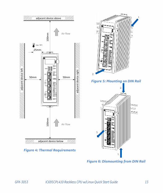
Note the thermal requirements for mounting the equipment (Figure 4).
Mount on the DIN rail per Figure 5. (1) Incline the unit so that the upper hooks of the DIN rail adaptor engage with the upper edge of the DIN rail. (2) Press on the lower part of the unit until you hear a click. The click indicates that the lower hooks of the DIN rail adaptor have engaged with the lower edge of the DIN rail.
Dismount from the DIN rail per Figure 6. (1) Grasp the unit securely. (2) Press down on the release bar as indicated. (3) Swivel the unit away from the DIN rail, then remove.
GFK-3053 IC695CPL410 Rackless CPU w/Linux Quick Start Guide 13
50mm 50mm
10
0mm
10
0mm
Air flow
adja
cen
t d
evi
ce r
igh
t
adja
cen
t d
evi
ce le
ft
adjacent device below
adjacent device above
25mm
Air flow
max. 70°C
Figure 4: Thermal Requirements
Figure 5: Mounting on DIN Rail
Figure 6: Dismounting from DIN Rail

14 July 2018 GFK-3053
If using the panel-mount adaptor, two options are available: mount using two screws (Figure 7) or, for more secure mounting, mount using four screws (Figure 8).
Figure 7: 2-screw panel mount
Figure 8: 4-screw panel mount
2.3. Installation in Hazardous Areas Refer to the Installation and Maintenance Requirements document, GFK-3004.

GFK-3053 IC695CPL410 Rackless CPU w/Linux Quick Start Guide 15
2.4. Connect to Power Supply The 24Vdc power input connector is located on the underside of the CPL410, as shown in Figure 9. The signal pinouts are also indicated.
The mating connector for the CPL410 24Vdc power input is the 3-pin Phoenix 1827716 shown in Figure 10. The power supply cable prepared by the user must use the specified mating connector.
The positive “+” and negative “-“ signals are required. FGND is optional but recommended.
For the mating connector, the compatible conductor size is from 24AWG to 16AWG. Strip the wires back 7mm before inserting into the connector. Tightening torque for the three signal screws is 2.2 in-Ibs (0.248Nm). Secure the mating connector to the power input connector via the two captive screws provided.
The user-supplied SELV3 power supply must supply voltage in the range of 18Vdc to 30Vdc.
Once the power supply cable (or compatible Energy Pack ACC403) has been attached to the CPL410 and the power supply has been turned on, the unit will start booting. There is no need to push any button.
The unit is equipped with built-in reverse polarity protection. If + and - are swapped the unit will not power-up. If + is connected to FGND, this will cause a short. The power supply needs to protect itself against this condition.
Figure 9: 24Vdc Power Input Connector
Figure 10: 24Vdc Power Input Mating Connector
2.4.1. Inrush Current The CPL410 may experience an inrush current of up to 49A for 15µs.
3 SELV = Safety Extra Low Voltage

16 July 2018 GFK-3053
2.4.2. Overvoltage Protection In the CPL410, the voltage to the inner loads is clamped to 33Vdc. At 33Vdc, the internal clamping diode starts conducting at 1mA. Any further increase in the voltage will cause the internal current fuse to blow and/or the clamping diode to break.
• CAUTION – EQUIPMENT REPAIR REQUIRED – Internal components must be
repaired at the factory; they are not field replaceable. Contact the GE support
team at https://ge-ip.force.com/communities/CC_Contact
2.4.3. Overcurrent Protection The function protects the internal circuitry from overcurrent conditions before serious damage can occur, such as overheating of the equipment. The fuse is rated for 4A continuous current. Once the sensed current reaches 40A, the fuse will blow after a period of 10ms to 100ms.
• CAUTION – EQUIPMENT REPAIR REQUIRED – Internal components must be
repaired at the factory; they are not field replaceable. Contact the GE support
team at https://ge-ip.force.com/communities/CC_Contact
2.5. Grounding Grounding via the FGND connection on the 3-pin 24Vdc In power header is recommended (see Section 2.4), but is not required if the CPL410 is mounted to a grounded metal panel. Furthermore, if an Energy Pack is connected, be sure to comply with grounding procedures as described in PACSystems RX3i Rackless Energy Pack IC695ACC403 Quick Start Guide, GFK-3000.

GFK-3053 IC695CPL410 Rackless CPU w/Linux Quick Start Guide 17
3. Module Start-up
3.1. You Will Need: • This PACSystems Rackless RX3i CPU. • A compatible SELV 24Vdc, 48W power supply (72W if Energy Pack attached). • (Optionally) A compatible Energy Pack, IC695ACC403, and corresponding cable. • If no Energy Pack is to be attached, use the power supply cable described in Section
2.4. • A DIN rail, typically mounted in an enclosure, as discussed above. Alternately,
mount the unit using the compatible panel-mount adaptor. • A computer running Proficy Machine Edition (PME) configuration and programming
software. PME Version 9.50 SIM 10 or later supports the CPL410. • Ethernet cable for connecting the PME programmer computer to the CPL410. • Additional cables, as needed, to connect each port employed in the application. • A very small slotted screwdriver to secure the 24Vdc mating connector. • A T8 Torx screwdriver, if the micro-SD slot cover is to be removed. Note that the
cover must be replaced to achieve immunity from electrical noise. • A T10 Torx screwdriver, if exchanging the mounting adaptors.

18 July 2018 GFK-3053
3.2. Basic Start-up Steps: For startup and configuration of the CPL410, complete the following steps. For full details on CPL410 operation, refer to the PACSystems RX3i and RX7i CPU Reference Manual, GFK-2222AE or later.
1. Mount the CPL410, as described in Section 2.2 and per the Installation and Maintenance Requirements document, GFK-3004.
2. Attach the user-supplied power supply cable as described in Section 2.4 if no Energy Pack is being used.
3. (optionally) Mount and attach the compatible Energy Pack, IC695ACC403, as described in the PACSystems RX3i Rackless Energy Pack IC695ACC403 Quick Start Guide, GFK-3000.
4. Turn on the power supply unit: the unit should then run without the need to press any buttons.
5. If not previously configured, configure the RX3i PLC using PME 9.50 SIM 10 or later, as described in the CPL410 PLC Configuration section below.
Note: When the ACC403 Energy Pack is powered up, a finite period is required to charge it up to its operating level. During this time, the Energy Pack will indicate this condition via its LEDs (refer to the PACSystems RX3i Rackless Energy Pack IC695ACC403 Quick Start Guide, GFK-3000).
The CPL410 will begin its boot cycle immediately upon power application. However, the embedded controller will not start its control until the ACC403 is charged. This typically takes 45 seconds or less. In the event the ACC403 is faulty or is not communicating, CPL410 commences operation without the Energy Pack.
Note: In the event of loss of power, with the ACC403 Energy Pack connected and charged up, the CPL410 remains on for 4 seconds to backup user memory into its non-volatile memory.

GFK-3053 IC695CPL410 Rackless CPU w/Linux Quick Start Guide 19
4. CPL410 PLC Configuration To configure, the CPL410, connect the computer running the PME programming software to any of the front-panel Ethernet ports. PME 9.50 SIM 10 or later is required
Configuration will either start out using the RX3i Rackless CPL410 template when creating a new project or will convert an existing project to the CPL410 using the Family Conversion feature in PME.
4.1. Backwards Compatibility To convert an existing project which uses any other PLC, use the Family Conversion feature in PME. Be aware of the constraints involved, as will be notified in PME. For instance, the first PROFINET Controller in an RX3i CPU320 application will be assigned to the embedded PROFINET Controller feature of the CPL410.
4.2. PROFINET Controller Configuration An Embedded PROFINET Controller may be configured on LAN2. To enable the PROFINET Controller in a CPL410 project, select the CPL410 target in the PME Navigator (Figure 11) and open the Hardware Configuration. On the Settings tab, change the designated LAN Mode of the selected port to PROFINET. The PROFINET Controller node description then displays that a PROFINET node exists on the selected LAN (under the CPL410). For further details, refer to the PACSystems RX3i PROFINET IO Controller User Manual, GFK-2571.
Figure 11: PME Navigator showing PROFINET node on LAN2

20 July 2018 GFK-3053
4.3. Redundancy Configuration It is possible to configure the RX3i PLC part of CPL410 as a Hot Standby Redundancy CPU with PROFINET IO. The two ports on LAN3 are used exclusively for this purpose: they provide a high-speed data synchronization link between the two CPUs. Connect the upper LAN3 port of the Primary CPU to the upper LAN3 port of the Secondary CPU and connect the lower LAN3 port of the Primary to the lower LAN3 port of the Secondary. Note that no additional hardware, other than the two redundant CPUs, may be connected to LAN3. To enable redundancy in a CPL410 project, select the CPL410 target in the PME Navigator and use the Property Inspector to change the Enable Redundancy target property to True. Important: Set the Background Window Timer to a minimum of 5ms in both the Primary and Backup CPL410 hardware configurations. The Background Window Timer setting may be found on the Scan Tab in the CPL410’s hardware configuration. Once configured for HSB Redundancy, the RACT and RBOK LEDs (Figure 1) become functional. RACT indicates the Local CPU is Ready & Active; RBOK indicates the Remote CPU is Ready. These two LEDs are also reflected in the Status Data of the CPU and are presented as OPC UA Variables. The OLED display includes two menu items used in conjunction with Redundancy:
• RDN Info provides status information via the OLED display.
• RDN Command permits the operator to perform a Role Switch.
For further details, refer to the PACSystems Hot Standby CPU Redundancy User Manual, GFK-2308 (rev L or later).

GFK-3053 IC695CPL410 Rackless CPU w/Linux Quick Start Guide 21
5. CPL410 Linux Ubuntu 16.04 Server LTS Linux is preinstalled on CPL410. Please note that the Server variant of Ubuntu does not offer a graphical desktop like GNOME or KDE, but only alphanumerical user interfaces (terminals). Additionally, the usage of graphic drivers is prevented by Kernel parameter to avoid unpredictable side effects (like CPU slow down due to overheating). This guide assumes the user is already familiar with Linux and therefore only covers topics relevant to CPL410 commissioning.
5.1. Start Linux After providing the CPL410 with power, Linux will begin to boot. The GPOK LED will start blinking to indicate when Linux has booted and is ready for user logins. (This may take about two minutes.)
5.2. Remote Login CPL410 is running a SSH service (daemon) which allows secure login from remote systems via the Ethernet network.
5.2.1. Log in via SSH over Ethernet Network
1. Connect the ETH port of the CPL410 (underside Ethernet port) to a DHCP server (see next section).
2. After CPL410 receives its IP Address from the DHCP server, the user can determine the active network parameters (incl. IP Address) via the display menu: GP Settings ->Network Config
3. On the remote system (e.g. a desktop PC or Laptop) the user will need a SSH client like Putty (https://putty.org/) or Kitty (http://www.9bis.net/kitty/). Enter the IP Address determined in the prior step, select the SSH protocol and open the connection.

22 July 2018 GFK-3053
Figure 12: Set up Connection from Remote System
4. After the connection has been established, the CPL410 login prompt appears:
Figure 13: Login from Remote System
Default user on CPL410 is admin with password admin. When logging in for the first time, you will be asked to provide a new password. Be sure to remember your new password, as there is no other way to access Linux without it.
o Default User Name: admin
o Default Password: admin

GFK-3053 IC695CPL410 Rackless CPU w/Linux Quick Start Guide 23
Note: For security reasons, it is common practice not to use the Superuser root account for login. Therefore, user root cannot directly login on CPL410, but user admin is granted SUDO rights to execute privileged commands. Prepend statement sudo to commands requiring privileges.
5.3. Network configuration
5.3.1. DHCP CPL410 Linux is configured by default to receive its IP Address via DHCP over the ETH Ethernet port (underside Ethernet connector - Figure 3). After receiving the network parameters, the active IP Address, together with other network information, can be determined via the OLED display menu GP Settings -> Network config, or by issuing the command ifconfig when logged in.
Note: A DHCP server is essential for the first remote login over SSH. Once logged in, the user can change the configuration to disable use of DHCP (see next section).
As the network 192.168.180.0/24 is used for CPL410 internal communication (see Section 5.7), the DHCP server must not assign any IP-Address from the address range 192.168.180.0 to 192.168.180.255 to the CPL410.
DHCP Troubleshooting: • If no IP address is assigned, use a laptop connected to the same network appliance
to assure that DHCP services are available.
• If no IP address is assigned and DHCP services have been verified, ensure that the ETH ethernet cable is plugged and cycle power or use the Display GP Settings->Commands->GP Reboot
5.3.2. Static IP Addresses Sometimes it is desirable to avoid use of DHCP. In this case, assign a distinct, static IP Address manually to the target CPL410. Both, DHCP and static IP Addresses are configured in the file /etc/network/interfaces.

24 July 2018 GFK-3053
5.3.3. Assign a Static IP Address To change from DHCP (default configuration) to static IP Addresses, edit the file /etc/network/interfaces manually, by using one of the available Editors (see below).
After configuration, reboot Linux either by issuing the reboot command or use the display menu GP settings -> Commands -> GP Reboot. Both only will reboot Linux and do not affect the PLC (PLC will continue to run).
Note: This is an essential setting. Make sure the entries are correct and that the device will be reachable with the designated IP Address; otherwise Linux will be inaccessible; Linux will need to be reset to factory installation.
As the network 192.168.180.0/24 is used for CPL410 internal communication (see Section 5.7), the DHCP server must not assign any IP-Address from the address range 192.168.180.0 to 192.168.180.255 to the CPL410.
5.3.4. Configure a Network Proxy If a network HTTP/HTTPS proxy server is used to route traffic from the intranet to the Internet, the environment variables http_proxy, https_proxy, ftp_proxy need to be set accordingly. To create these variables permanently and for all users edit the /etc/environment file.
Proxy Settings for APT Package Management The APT package management (apt, apt-get commands) uses a different configuration file for proxy settings: /etc/apt/apt.conf.
5.4. Linux Software
5.4.1. Pre-installed Editors By default, the following Editors are available:
- VIM
- Nano
- Midnight Commander (mc)

GFK-3053 IC695CPL410 Rackless CPU w/Linux Quick Start Guide 25
5.4.2. Additional Installed Packages The CPL410 Linux installation is based on the Ubuntu 16.04 LTS Server distribution. Additional to this software set some more packages have been preinstalled mainly to enable interfacing with the PACS runtime, but also to allow development of Python based OPC-UA communication applications.
The following is the list of additional installed software. Each user can update these and optionally install software of their own choosing (refer to Section 5.4.3).
• build-essential
• linux-generic
• swig
• cmake
• python2.7-dev
• libssl-dev
• libxml2-dev
• sqlite3
• apache2
• libapache2-mod-wsgi-py3
• php
• php-sqlite3
• phpLiteAdmin
• zutils
• gdisk
• mc
• FreeOpcUa
• FreeOpcUa Documentation (/var/www/html/FreeOpcUa)
• python-concurrent.futures
• python-enum34
• python-trollius
• python-dateutil
• python-tz
• python-lxml
• python-sphinx
• python3-dateutil
• python3-tz
• python3-lxml
• python3-crypto
• python3-cryptography

26 July 2018 GFK-3053
Packages/SW by GE Automation &Controls: • opc2sqlite.py Python OPCUA Sqlite example in /home/admin
• empty sqlite database sampledb in /home/admin/sqlite
• /usr/bin/predix_scripts/...
• /usr/bin/efaSmiFileManager.py
• /usr/bin/efaSmiApp
• /lib/systemd/system/efasmiapp.service
• /lib/systemd/system/efasmifilemanager.service
• /lib/systemd/system/fastatemanager.service
• /var/ge/FieldAgentInfo/faState.josn
• /sbin/xtables-multi.wrapper
• CPL410 Example Web page, Style sheets,… in /var/www/html
• Example OPCUA-Python Web application in /var/www/cgi-bin/PyOpcUaWeb.py
• Hypervisor Open Source drivers in /boot/rth
5.4.3. Install or Update Packages CPL410 Linux is open to software individually installed by customers. Standard Debian (Ubuntu is Debian based) package tools may be used to add, delete or update software packages.
Note: Please keep in mind, that preinstalled Ubuntu is a server variant, not offering a graphical desktop like KDE or GNOME. Therefore, installing graphical programs like Web browsers only makes sense if additionally installing a X11 windowing system (or similar) and forwarding the output to a remote device (the CPL410 Display Port cannot be used for graphical output).
On the command line apt (Advanced Packaging Tool) or apt-get command is used to install, update or delete a software packages. Both commands are privileged commands, therefore, sudo needs to be prepended if not logged in as root.
For more details see Ubuntu help page about Package Management: https://help.ubuntu.com/16.04/serverguide/package-management.html.en
Note: Depending on the software repositories configured in /etc/apt/sources.list file and in the /etc/apt/sources.list.d directory, new software packages are typically downloaded from external repositories. A working Internet connection is therefore required to install or update packages.

GFK-3053 IC695CPL410 Rackless CPU w/Linux Quick Start Guide 27
Note: Upgrading a system also can include the Linux Kernel and the initial RAM disk, both located in the /boot directory. If a new Kernel or RAM disk has been installed by upgrade, make sure the symbolic links /boot/vmlinuz and /boot/initrd.img are pointing to the latest Kernel (RAM disk version). After a new Linux Kernel has been installed, and the links have been set accordingly, a power cycle is necessary to make the Kernel change effective. Whenever a new Kernel version is active, drivers not provided by Ubuntu need to be recompiled. Two drivers are needed for CPL410 communication with the PLC runtime: these are recompiled on the fly, whenever a new Kernel is detected. Driver archives are located in the /boot/rth folder and must not be deleted.
Note: There always is a risk of damage to the Linux installation when upgrading the system, especially if the Kernel is being updated. Consider performing such an upgrade in a protected environment before attempting such an upgrade on a production system.
5.5. CPL410 File Exchange The ssh service, mentioned earlier regarding remote login, can also be used to copy files from a remote computer to the CPL410 Linux and vice versa. There are several Windows tools freely available to make use of this service from a Windows PC, like WinSCP (https://winscp.net) or FileZilla (https://filezilla-project.org/). Please configure either the SCP or the SFTP protocol when connecting with this tools to the SSH service of CPL410. In Linux, the command line program scp can be used to copy a file from one CPL410 to another or to another SSH server.
Please pay attention to the CPL410 Secure Deployment Guide (GFK3055) regarding SSH key exchange and key generation.
5.6. Sample Web Page CPL410 instantiates anApache2 Server and provides an example Webpage, offering system information and sample applications. The page can be reached by entering the CPL410 IP-Address into a Web browser: https://<ip-Address>
Current IP-Address can be determined via the display menu: GP Settings ->Network Config.

28 July 2018 GFK-3053
For security reasons all requests using the HTTP protocol are redirected to the encrypted HTTPS protocol. This can be modified by editing the Apache2 configuration file /etc/apache2/sites-available/ 000-default.conf.
As CPL410 uses the Ubuntu default self-signed certificate for encrypted HTTPS communication, a warning is displayed when opening the CPL410 Webpage the first time. Please add a security exception in the browser or provide a SSL certificate for the Apache Server to display the CPL410 Webpage properly.
All pages presented here, are in the /var/www/html directory and may be modified or deleted as needed. They are provided for demonstration purposes only.
5.6.1. CPL410 Information
1) CPL410 order number 2) CPL410 serial number of the device 3)
Current CPL410 Linux system time and date 4) 5) Linux Kernel version currently running 6) Current Ubuntu Version 7) IP-Address used by CPL410 Linux on bottom ETH port

GFK-3053 IC695CPL410 Rackless CPU w/Linux Quick Start Guide 29
8) IP-Address used for communication with runtime
5.6.2. CPL410 Example Webpages and Applications
1) Link to the phpLiteAdmin Tool for administering the example SQLite database
located in the user “admin” home directory: /home/admin/sqlite/sampledb (see also Section 5.9)
2) This link calls the local default Webpage normally provided by Ubuntu as start page.
3) Link to the Ubuntu Server Guide in the Internet. Working Internet connection is needed to display this page.
4) Local Ubuntu Server Guide in PDF format
5) Link to the CPL410 PLC Runtime Update page. This link only works if connected to the CPL410 LAN1 front Ethernet port using the IP-Address 192.168.0.100 (Port also used for the PME programming system). If this port is configured for a different IP-Address you need to adapt the /var/www/html/index.php file accordingly (near line 106).
6) Documentation for the Pure Python OPC-UA Library used to exchange data with the PLC runtime via OPC-UA (see also Section 5.7)
7) Link to an example Webpage demonstrating the OPC-UA data exchange and database storage. This link works properly only, if a PLC program exists exporting OPC-UA variables (see also Section 5.7).

30 July 2018 GFK-3053
8) Information about Open Source Licenses and Open Source used for CPL410.
5.7. Data Exchange with PLC - OPC-UA On CPL410 the Control Engine (PLC) and Linux are running in parallel, strictly separated and encapsulated by a Hypervisor in so called Virtual Machines (VM). The only link between these two worlds is a virtual network (VNIC) simulating an Ethernet connection in a memory, shared between both VMs. The following Figure is illustrating the separation in VMs (Linux Ubuntu and VxWorks) and the connection between both VMs (VNIC: Virtual Network Interface Card):
Figure 14: Data Exchange PLC-OPC-UA
To exchange data over this virtual network, an OPC-UA server is instantiated in the PLC, implementing the OPC-UA protocol, thus allowing a Linux OPC-UA Client to request and set PLC variables.

GFK-3053 IC695CPL410 Rackless CPU w/Linux Quick Start Guide 31
OPC-UA protocol makes use of the operating systems TCP/IP stack to send data over the virtual network. The TCP/IP-Parameters for this network are as follows:
PLC: 192.168.180.2
Linux: 192.168.180.1
Network Mask: 255.255.255.0
OPC-UA Server Port: 4840
The network part of the IP-Address as well as the PLC IP-Address cannot be changed by user. The Linux IP-Address of this network can be changed in the /etc/init.d/ rthinitVirt script, but it is not recommended to do so.
Note: As the network 192.168.180.0/24 is used for the virtual network between the CPL410 VMs, this network must not be used on any physical Ethernet port.
Note: - OPC-UA is the only way to exchange data with the PLC over the VNIC. - OPC-UA-Server is listening not only on the VNIC, but also on the front-panel Ethernet ports.
To demonstrate the OPC-UA communication, CPL410 has installed the freely available Python Library “Pure Python OPC-UA”. This library is distributed under the LGPL license and can be found here: https://github.com/FreeOpcUa/python-opcua .
“Pure Python OPC-UA” library documentation is available on CPL410 via the CPL410 Web page (see Section 5.6.2).
In the home directory of user admin a very basic example, based on the “Pure Python OPC-UA” library, is provided (/home/admin/opc2sqlite.py), demonstrating how to read a variable named Cosine form PLC and store the content of this variable in a SQLite database (see Section 5.9 about SQLite).
Execute this Python script as user admin by the following command line sequence: python /home/admin/opc2sqlite.py
This reads the current value of the variable Cosine in the PLC and stores it in the SQLite database /home/admin/sqlite/sampledb.
Note: To successfully read or write PLC variables via OPC-UA, those PLC variables need to be published/exported in the PLC project:

32 July 2018 GFK-3053
The Python example mentioned above especially expects a variable named Cosine to be exported. Please modify the script, if a different variable shall be used.
A more sophisticated example can be found via the CPL410 Web page (see Section 5.6.2). This example is also implemented in Python and based on “Pure Python OPC-UA” library. It is executed by the Apache2 Webserver as a CGI script, generating dynamically HTML code send to a Web browser. To be executable by Apache2, it is stored in the Apache CGI directory /var/www/cgi-bin and named PyOpcUaWeb.py. The database used by the PyOpcUaWeb.py script to store variables content is the same as used by the example mentioned above: /home/admin/sqlite/sampled.

GFK-3053 IC695CPL410 Rackless CPU w/Linux Quick Start Guide 33
1) When the Web page is opened, the Python script is executed by the
Webserver. The script connects to the OPC-UA server in the PLC and ask for the names available (published) for OPC-UA. Those names are added to this list box. In the list box an entry can be selected for further operations.

34 July 2018 GFK-3053
2) With the Variable selected in (1) 3 actions can be performed:
a. Get the value of the selected variable. Result is shown in (4),(5),(6),(7)
b. Set the variable to the value entered in (3). After the variable has been set the current value is read and displayed in the output area.
c. Get the value of the selected variable and store data in SQLite database
3) The value entered here is used for the “Set Value” action
4),5),6),7) Output Area showing the name, the value, the OPC-UA variable type and the time PLC time when the variable has been captured.
8) Via this link the phpLiteAdmin tool can be started to display and modify the SQLite database, where the “Get and Store” action stores the variables (see also 5.9).
5.8. Factory Reset It might happen that a user locks him/herself out from Linux, or Linux fails to start following a misconfiguration. In such cases, Linux can be restored to its original manufacturer settings:
• Factory Reset can be triggered via the OLED-Display Menu: GP Settings->Commands->Factory Reset.
• After the Factory Reset has been triggered, a manual power cycle must be executed by pressing the power button for more than 4 seconds.
Note: Please ensure, the PLC and controlled facilities are in a secure state when cycling power. PLC Stop mode is recommended.
• When CPL410 boots up again, the Linux root (/dev/sda8) and boot (/dev/sda9) partitions are formatted and the original factory software is installed. During the restore process “Resetting GP” is shown on the display when selecting the “GP Settings” menu. Also, the LED GPOK is off during reset. Restoration is finished when the GPOK LED blinks again.
Note: All data, all user modifications, all updates etc. on these partitions are deleted and are unrecoverable following factory reset. Therefore, consider making backups of all changes applied to Linux frequently.

GFK-3053 IC695CPL410 Rackless CPU w/Linux Quick Start Guide 35
• The original factory software load is extracted from archives located on the /dev/sda12 partition. This partition is not mounted by default and must not be changed by users.
• The home partition (/dev/sda10: folder /home and below), where the customer data is expected to be stored, is not impacted.
5.9. SQLite Demonstration Database SQLite ( https://sqlite.org/ ) is an embedded, file based database engine. SQLite database files are directly modified via library calls and not via a server interface respectively a network service. Therefore, SQLite cannot be accessed remotely and is only suitable for small amounts of data and slow data rates, it is normally not used in a production environment. SQLite and related libraries have been installed on CPL410 for demonstration purposes only.
The Python examples mentioned above, all use the same SQLite database to store data: /home/admin/sqlite/sampled.
For administration and visualization of the database content, a small, Web based tool called phpLiteAdmin ( https://www.phpliteadmin.org/) has been installed in the document root of the Apache2 Webserver (/var/www/html). In this directory the tool itself (phpliteadmin.php) and its configuration (phpliteadmin.config.php) reside. In the configuration the admin password and the database directory have been changed as follows:
User: admin
Password: cplsqladmin
Database Directory: /home/admin/sqlite
phpLiteAdmin can either be accessed by following the links in the CPL410 example Web pages or by directly entering the URL https://<CPL410 Linux IpP-Address>/phpliteadmin.php in a Web browser.

36 July 2018 GFK-3053
Figure 15: phpLiteAdmin
The table valutable in the sample database (sampled) contains the variables stored by the Python examples:
Figure 16: Variables Stored by Python Examples
Please refer to the online documentation to learn more about the usage of this tool.

GFK-3053 IC695CPL410 Rackless CPU w/Linux Quick Start Guide 37
5.10. GPOK LED The General-Purpose operating system OK LED (GPOK LED) signals the status of the Linux operating system. If this LED is blinking Linux is running. As all front LEDs and the OLED display are controlled by the real-time Control Engine, Linux can´t set the GPOK LED directly, but needs to signal status indirectly. Two Linux processes -faStateManager and efaSmiApp- are managing the communication to share information, like status or IP-Address, with the Control Engine. Two files, which are written respectively monitored by these processes, may be of interest for users:
1. /var/ge/FieldAgentInfo/faState.json : This file signals the current Linux state to the Control Engine, thus defining the blink rate of the GPOK LED. This file contains a JSON structure with 3 variables:
a. osRunning: if true, GPOK blinking slowly. This is the default state, indicating that Linux is up and running.
b. predixMachineRunning: if true, GPOK is blinking fast; this variable could be used to signal a running user process.
c. predixMachineCloudConnected: if true, GPOK is solid; this variable could be used to indicate an established internet connection.
d. Default: {"osRunning": true, "predixMachineCloudConnected": false, "predixMachineRunning": false }
e. Only the first line of this file is evaluated.
f. There are 3 more variables in this JSON file, which are currently not supported by CPL410 (.wifiDisabled, configurationModeOn, recentMachineDataTransferred)
g. User can manually modify this file to change the GPOK LEDs behavior, or automatically update the file to signal different states of an application.
2. /var/ge/FieldAgentInfo/HwInfo.txt: This file contains the catalog and the serial number of the CPL410. This data is read by the Control Engine from a Factory EEProm and transferred to Linux into this file.

38 July 2018 GFK-3053
6. Additional Information Proficy Logic Developer-PLC Getting Started GFK-1918
PACSystems RX7i, RX3i and RSTi-EP CPU Reference Manual GFK-2222
PACSystems RX7i, RX3i and RSTi-EP TCP/IP Ethernet Communications User’s Manual
GFK-2224
PACSystems TCP/IP Ethernet Communications Station Manager Manual GFK-2225
PACSystems Hot Standby CPU Redundancy User Manual GFK-2308
PACSystems RX3i System Manual GFK-2314
PACSystems RXi, RX7i, RX3i and RSTi-EP Controller Secure Deployment Guide GFK-2830
PACSystems Controllers with Linux Secure Deployment Guide GFK-5055
PACSystems RX3i IC695CPL410 1.2GHz 64MB Rackless CPU w/Linux User Manual
GFK-5056
PACSystems RX7i, RX3i and RSTi-EP CPU Programmer’s Reference Manual GFK-2950
PACSystems RX3i PROFINET IO Controller User Manual GFK-2571
PROFINET I/O Devices Secure Deployment Guide GFK-2904
PACSystems RX3i Rackless Energy Pack IC695ACC403 Quick Start Guide GFK-3000
Field Agent User’s Guide GFK-2993
User manuals, product updates and other information sources are available on the Support website, www.geautomation.com under Controllers and IO, RX3i Controllers.

GE Automation & Controls Contact Information Americas: 1-800-433-2682 or 1-434-978-5100 Global regional phone numbers are available on our web site www.geautomation.com Copyright © 2018 General Electric Company. All Rights Reserved. * Trademark of General Electric Company and/or its subsidiaries. All other trademarks are property of their respective holders GFK-3053
For binaries that you receive in this distribution that are licensed under any version of the GNU General Public License (GPL) or the GNU Library/Lesser General Public License (LGPL), you can receive, for a fee of no more than our cost of physically performing the distribution, a complete machine-readable copy of the source code by sending a written request to:
Automation & Controls GE Attn: General Counsel 2500 Austin Drive Charlottesville, VA 22911
Your request should include: (i) the name of the covered binary, (ii) the version number of the product containing the covered binary, (iii) your name, (iv) your company name (if applicable) and (v) your return mailing and email address.
This offer is valid for three (3) years after the date of the last distribution of this particular version of this product. For any code in this product covered by version 3 of the GNU General Public License (GPL), then this offer is valid for those who possess the object code for either i) for the aforementioned three (3) years, or ii) until the date on which we cease offering both spare parts and customer support for this particular version of this product, whichever occurs last.
https://digitalsupport.ge.com/communities/en_US/Documentation/PACSystems-IC695CPL410-Open-Source-Software-information